Thermo MeasureTech 1440-15 Model 1440 Radar Level Gauge User Manual AccuWave Installation Manual
Thermo MeasureTech Model 1440 Radar Level Gauge AccuWave Installation Manual
Contents
- 1. Operating Manual for 1440
- 2. Installation Manual for 1440
Installation Manual for 1440

Accu-Wave Radar Gauge
Radar-Based Continuous Level Measurement
Installation Manual
DRAFT
Part No. 717790
Accu-Wave Radar Gauge
Radar-Based Continuous Level Measurement
Installation Manual
DRAFT
Part No. 717790
Version 1.0
March 2000
Disclaimer
TN Technologies has made every effort to ensure the accuracy and completeness of this manual.
However, we cannot be responsible for errors, omissions or any loss of data as a result of errors or
omissions. TN Technologies reserves the right to make changes to the manual or improvements to the
product at any time without notice.
The material in this manual is proprietary and cannot be reproduced in any form without express written
consent from TN Technologies.
Refer to the equipment tag shipped with your gauge to verify the certifications for hazardous location use
applicable to your gauge. Refer to the Installation Manual and the Installation/Wiring Drawings for
installation instructions.
Trademarks
All registered trademarks are the property of their respective companies.
© 2000 TN Technologies
TN Technologies
2555 North Interstate 35
P. O. Box 800
Round Rock, Texas 78680-0800
TN Technologies also offers a complete line of portable x-ray fluorescence analyzers.

Accu-Wave Table of Contents
i TN Technologies
Table of Contents
Chapter 1 Introduction ................................................................................................................................ 1-1
Description ..................................................................................................................................................... 1-1
Features and Benefits ...................................................................................................................................... 1-3
How the Accu-Wave Works............................................................................................................................ 1-4
How to Use This Manual................................................................................................................................. 1-5
TN Technologies’ Service Department ............................................................................................................ 1-5
Chapter 2 Hardware Installation................................................................................................................. 2-1
Licensing........................................................................................................................................................ 2-1
Hazardous Location Approvals........................................................................................................................ 2-2
Selecting a Location........................................................................................................................................ 2-2
Mounting the Gauge........................................................................................................................................ 2-4
Chapter 3 Wiring Procedures...................................................................................................................... 3-1
Initial Wiring Preparations .............................................................................................................................. 3-1
Wiring Instructions ......................................................................................................................................... 3-2
Appendix A How to Return Equipment for Service ...................................................................................... A-1
Appendix B Parts List.................................................................................................................................... B-1
Appendix C Specifications.............................................................................................................................. C-1
Appendix D Installation Drawings................................................................................................................. D-1

Accu-Wave Chapter 1 Introduction
TN Technologies 1-1
Chapter 1 Introduction
The Accu-Wave Model 1440 Radar Level Gauge uses a microwave signal to
continuously measure the level of the process material. The Accu-Wave provides better
performance than sonic measurement systems, particularly in hostile environments,
because the microwave signal is unaffected by mist, surface agitation, temperature
changes, or pressure changes. The standard menu-driven user interface, with built–in help
screens, the optional Windows-based Setup Software are designed to make the gauge
easy to set up and operate.
The Accu-Wave transmits a microwave signal that is reflected from the surface of the
process material. The reflected signal or echo is received by the Accu-Wave. The Digital
Signal Processing (DSP) software detects the echo and computes the distance to the
liquid or solid material in the tank. The Accu-Wave firmware uses the distance
measurement to calculate level, volume, and other user-selected measurements.
Description
The Accu-Wave Radar Level gauge consists of an integrated sensor and transmitter with
the microwave sensor and transmitter circuitry combined on a single electronics board.
The microwave signal is launched from the bottom of the board via a cup/probe assembly
into the antenna. The antenna serves to focus the transmitted signal as well as to receive
the reflected echo. Currently, the Accu-Wave is available with dielectric rod antennas.
Horn antennas will be available as a future option.
Antennas
The standard antenna configuration for the Accu-Wave gauge consists of a dielectric-
filled, 1 inch O.D. stainless steel waveguide with a dielectric rod antenna. The dielectric
rod antenna is available in either polypropylene or Teflon (PTFE). The stainless steel (SS
316) waveguide material is swaged (crimped) over the dielectric-fill material. The swage
serves both as a process seal as well as a pressure seal. The PTFE antenna design also
uses O-rings to ensure the integrity of the process seal. Viton and Kalrez O-rings are
available.
Horn antennas, with diameters ranging from 2 to 8 in., will be available as a future
option.
Mounting Configurations
The dielectric rod antennas are fitted with either a 1-inch NPT threaded bushing, welded
to the waveguide, or with a welded flange. The available flanges sizes are 150 lb. or 300
lb., with diameters of 2, 3, 4, or 6 inches. Waveguides are provided in lengths of 6, 9, 12,
or 15 inches lengths, where the length refers to the portion of the waveguide that extends
below the bushing or the flange. For optimum performance, the end of the waveguide
should extend to the bottom of the tank nozzle or below.
Level measurements can be made even when the process material level is in contact with
the dielectric antenna to within ~3.5 inches of the bottom of the steel waveguide.

Chapter 1 Introduction Accu-Wave
1-2 TN Technologies
Measurement accuracy, however, is degraded when the process level is above the bottom
of the probe.
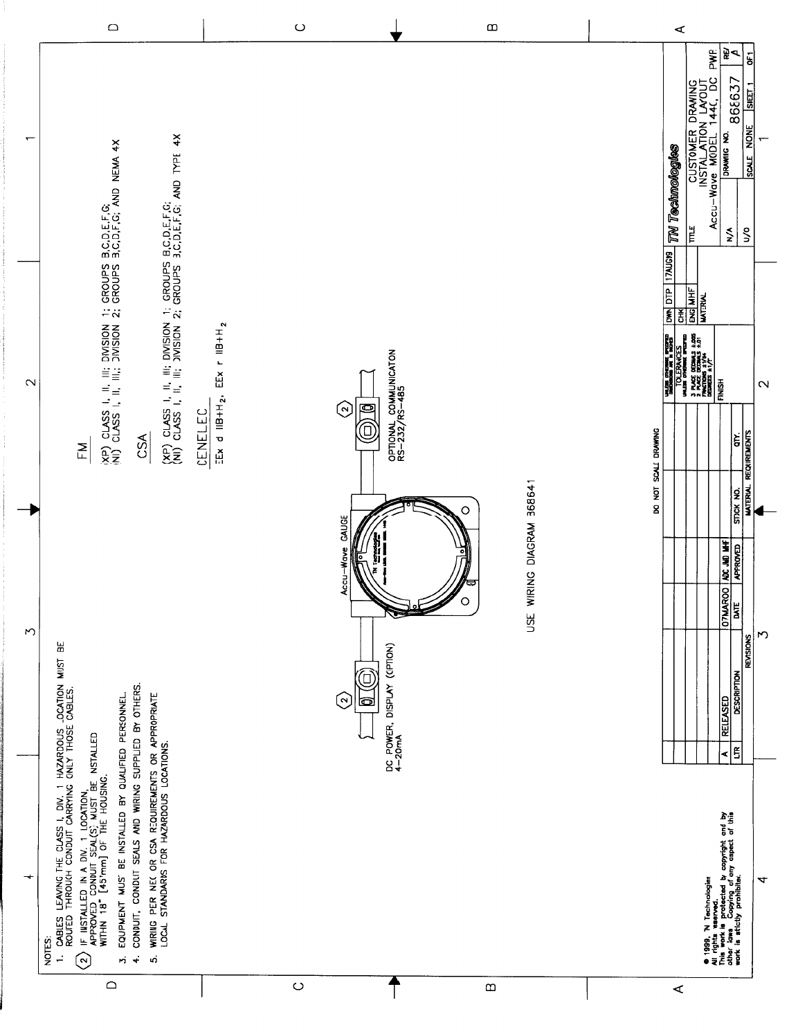
Approvals
The Accu-Wave is certified for use in hazardous locations as follows (approvals are
pending as of 1 March 2000):
FM
• Class I, II, III, Division 1, Groups B, C, D, E, F, G
• Class I, II, III, Division 2, Groups B, C, D, F, G
• NEMA 4X
CSA
• Class I, II, III, Division 1, Groups B, C, D, E, F, G
• Class I, II, III, Division 2, Groups B, C, D, E, F, G
• TYPE 4X
CENELEC
• EEx d IIB + H2
• Eex n IIB + H2
See Appendix C for additional information regarding specifications and safety approvals.
Note: Verification of chemical compatibility with the exposed antenna materials is
ultimately the responsibility of the customer.
Sensor-Transmitter
The sensor and transmitter are integrated on a single electronics board. The transmitter
detects the signal reflected from the process material, determines the distance to the
surface of the process material, and calculates other measurement values. These values
can be displayed on a local/remote display, sent to the serial ports (RS-485 standard, RS-
232 optional), and can be used to drive the 4-20 mA current output or process alarms.
The RS-485 and optional RS-232 serial ports support communications from a PC with
the Accu-Wave Window’s based Setup Software, a PC with terminal emulation software,
or a TN Technologies' Hand Held Terminal.
The Accu-Wave supports 4-20 mA current output, serial communications, a contact
closure input, and a 2-line local/remote display. The Accu-Wave inputs and outputs are
summarized in the following Input/Output Characteristics Table.

Accu-Wave Chapter 1 Introduction
TN Technologies 1-3
Input/Output Characteristics
Type Characteristics Comments
Current output 0-20 mA dc (adjustable range)
Isolated, Loop-Powered,
24 Vdc Nominal Supply
Voltage, 700 ohm max. load
Default range is 4-20 mA dc.
One current output is provided.
Serial
communications RS485: One terminal block and
one RJ11 Jack
RS 232: One terminal block
(Requires optional board.)
Half-duplex party line
communication to host computer
or Hand-Held Terminal.
Full duplex communication with
a remote terminal or PC.
Contact closure
input One (1) contact closure input is
provided. The user can assign a command
to execute based on user-provided
contact opening or closure input
to the gauge.
Remote Display 2 Line x 16 Character Display
- Backlit
Features and Benefits
Dynamic Menu System
You see only the menu options pertinent to your application. The initial “Set up level, ...”
menu takes you through a basic setup to get your instrument up and running quickly.
Help screens are available at appropriate points.
Built-in Volume Measurement
Select one of the pre-defined tank shapes, enter its dimensions, and the gauge computes
volume from an internal equation library. Alternately, you can define volume as a
polynomial expression based on the level (height) or as a break table of volume and
height value pairs.
Instantaneous Response
TN Technologies Dynamic Process TrackingTM (DPT) ensures no lag time in the system
response to level changes. When sudden process changes occur, the DPT feature reduces
the normal averaging time constant by a factor of eight, ensuring a smooth and rapid
output response. When the process stabilizes, the longer time constant is applied to
reduce spurious fluctuations in the measurement. In this way, actual changes in process
level are immediately reflected in the transmitter output, while the effects of signal
variations from turbulence and other short term factors on the measurement are greatly
reduced.

Chapter 1 Introduction Accu-Wave
1-4 TN Technologies
Extensive Alarms
You can set up as many as 16 process alarms in addition to system fault alarms and
warning alarms.
Quick and Easy Setup
The menus take you through the setup procedure step–by–step. Built-in help screens are
provided at appropriate points in the menu structure.
Multiple Readouts
You can select up to six of the following values for display: level, distance, volume,
unfilled volume, percent full, percent empty, percent distance, percent level, signal
strength, or alarm relay status. The screen automatically displays the measurement values
three at a time in alternation. The measurement values can also be sent to a remote
terminal or a computer.
Marker Sweep Software
TN Technologies’ patented Marker Sweep software continually adjusts the transmitter
output signal to maintain linearity. This highly consistent microwave signal ensures
reliable, stable system operation and accurate level measurements.
Digital Signal Processing (DSP)
The gauge uses DSP hardware and software to process the received microwave signal
(the echo) and to provide accurate, real-time measurements of the distance to the surface
of the process material.
How the Accu-Wave Works
The sensor generates a microwave signal composed of electromagnetic waves – two
perpendicular oscillating fields (electric and magnetic) that travel together. The
transmitted signal is reflected from the surface of the process material. This echo is
detected and evaluated for changes in frequency to determine the distance to the liquid or
solid material in the tank.
The Marker Sweep software continually adjusts the signal output to maintain the linearity
of the transmitted frequency sweep. This highly consistent microwave signal ensures that
changes in level are reported accurately in real-time. Dynamic Process Tracking software
ensures quick system response to changing process levels by automatically reducing the
response time when level changes occur. A variety of tools are provided in the menus to
“fine tune” the signal in order to eliminate many of the problems associated with
measuring levels in an active process.
TN’s exclusive DSP software processes the microwave signal and converts it to
measurement information displayed in the readout. You can also program measurements
to drive alarms, or open and close switches. The alarms, user inputs, and selected outputs
are saved in non-volatile memory.

Accu-Wave Chapter 1 Introduction
TN Technologies 1-5
Automatic verification and error correction software continuously monitors system
operations. System faults can be programmed to set off alarms.
How to Use This Manual
This manual provides installation and maintenance/troubleshooting procedures for the
Accu-Wave gauge.
Installation and Maintenance
Note: Reduced-size copies of the drawings referenced in this manual are
included in .
Chapter 2, “Hardware Installation,” provides instructions for mounting the Accu-Wave
sensor and transmitter.
Chapter 3, “Wiring Procedures,” describes how to wire the power source to the gauge and
other wiring, such as the current output and serial communications.
Additional Information
Appendix A, “How to Return Equipment for Service,” gives you shipping information for
returning equipment to TN Technologies for service.
Appendix B, “Parts List,” lists the parts of the Accu-Wave. Refer to this list if you need
to order parts.
Appendix C, “Specifications,” contains the specifications for the Accu-Wave.
Appendix D, “Installation Drawings,” contains reduced-size copies of the drawings
referenced in this manual.
Setting Up and Using the Gauge
The companion manual “Accu-Wave Operation Manual” (717791) provides detailed
information on how to set up the Accu-Wave software and operate the Accu-Wave
gauge.
TN Technologies’ Service Department
The TN Technical Services Department is available to help you with any problems you
may have installing or operating your gauge. Call us with your questions or comments:
• Phone: (800) 736–0801 (US only)
• Main Office: (512) 388–9100
• FAX: (512) 388-9200

Accu-Wave Chapter 2 Hardware Installation
TN Technologies 2-1
Chapter 2 Hardware Installation
Licensing
All microwave frequency tuning is completed at the factory (TN Technologies Inc.,
Round Rock, Texas).
United States
For installations on metal tanks, the Accu-Wave complies with FCC Part 15
requirements, FCC ID MCO1440-15, and no additional licensing is required (Part 15
certification is pending)
Note:
Operation under Part 15 of the FCC Rules is subject to the two following
conditions: (1) this device may not cause harmful interference, and (2) this
device must accept any interference received, including interference that
may cause undesired operation.
For installations other than on metal tanks, you must obtain and display a FCC Part 90
license at the installation site, FCC ID MCO1440 (Part 90 certification is pending). TN
Technologies can assist you with licensing. For assistance, call or fax one of the
following numbers:
• Phone: (800) 736-0801 (US only)
• Main Office: (512) 388-9100
• FAX: (512) 388-9200
Canada
(i) This device shall be installed and operated in a completely enclosed metal
container to prevent RF emission which otherwise can interfere with
aeronautical navigation. Installation shall be done by trained installers, in
strict compliance with the manufacturer’s instructions.
(ii) The user of this device is on a “no-protection non-interference” basis. That
is, the user shall accept Government and NAV CANADA operations of high
powered radar in the same frequency band which may interfere with this
device. Devices found to interfere with Government and NAV CANADA
operations will be required to be removed.
(iii) The user is required to notify the TN Technologies at 2555 N. IH 35, Round
Rock, TX, 78680 of the postal address of the user, the address where the
device is installed, the device model number, and the date of installation.

Chapter 2 Hardware Installation Accu-Wave
2-2 TN Technologies
Hazardous Location Approvals
The Accu-Wave is certified for use in hazardous locations as follows (approvals are
pending as of 1 March 2000):
FM
• Class I, II, III, Division 1, Groups B, C, D, E, F, G
• Class I, II, III, Division 2, Groups B, C, D, F, G
• NEMA 4X
CSA
• Class I, II, III, Division 1, Groups B, C, D, E, F, G
• Class I, II, III, Division 2, Groups B, C, D, E, F, G
• TYPE 4X
CENELEC
• EEx d IIB + H2
• Eex n IIB + H2
Warning: Do not locate the unit in any hazardous area other than those approved.
Follow all instructions on the installation drawings.
Do not apply power to the unit in any hazardous area unless the safety
ground is properly wired inside the unit and the cover is properly
installed. See Chapter 3 for installation wiring instructions.
Hazardous Location Installations: The cable entries must be sealed per
the Installation Layout Drawing (868502).
Non-Hazardous Location Installations: The cable entries into the
enclosure must be sealed with a compound to protect against the
passage of gas or vapors. The sealing compound should not be
affected by the surrounding atmosphere or liquids. The minimum
thickness of the sealing compound should be 5/8 in (16 mm).
Selecting a Location
Selecting a good location to mount the transmitter can ensure the accuracy and ease of
operation of your gauge.
Guidelines
Follow these guidelines when selecting a location for the Accu-Wave gauge:
1. The operating temperature range is –40ΟC to 70ΟC (–40ΟF to 158ΟF).
2. The sensor should be mounted above the smoothest portion of the process
material surface.

Accu-Wave Chapter 2 Hardware Installation
TN Technologies 2-3
3. There should be a clear path between the sensor and process material to avoid
false reflections. Verify that the path is clear of pipes, beams, or any intermittent
liquid sprays that could block the microwave beam. Also try to locate the sensor
to keep the beam path (approximately 18º wide) clear of the following:
− Turbulence, splashing, or waves such as those caused by filling,
recirculation, or sparging of light material entrances near the bottom of the
tank.
− Pipe entrances near the top or side of the tank.
− Agitator blade passing directly through the beam path. If this can not be
avoided, use the “agitator reject time” feature on the “Radar fine tuning”
menu, discussed in the Accu-Wave Operation Manual (717791).
− Vortices caused by baffles, drains, or any other obstructions.
4. The mounting location should also avoid horizontal structural surfaces such as
baffle support brackets, side wall joints, and so forth, because these surfaces
reflect a strong false signal. If this cannot be avoided, refer to the section “False
Echo Management” in Chapter 5 of the Operation Manual (717791).
5. If the vessel has a dome top, a good guideline is to mount the sensor away from
the vessel’s center point by at least 10% of the vessel diameter.
Note: If the sensor is mounted in the center of the vessel, the dome top will act as
a parabolic antenna, potentially enhancing “false” echoes due to multiple
reflections of the transmitted energy.
The tank’s nozzle must meet the following requirements.
1. Rod antennas: the internal diameter of the nozzle must be larger than 1 inch. For
best performance, the bottom of the stainless steel waveguide tube must be even
with the bottom of the nozzle or extend below the bottom of the nozzle.
2. Intrusive horn antennas: the internal diameter must exceed the horn diameter (3,
4, 6, or 8 inches). The nozzle must be free of burrs and other obstructions.
3. Process isolation horn antennas: The internal diameter of the nozzle section
needs to be the same along the length of the nozzle. The nozzle must be free of
weld beads, steps, burrs, or abrupt changes in nozzle diameter.
4. Nozzle must meet or exceed tank pressure requirements.
5. Align nozzle within 3º of vertical (verify this with a carpenter’s combination
level). Flange surface must be aligned within 3º of horizontal (verify this with a
carpenter’s combination level).
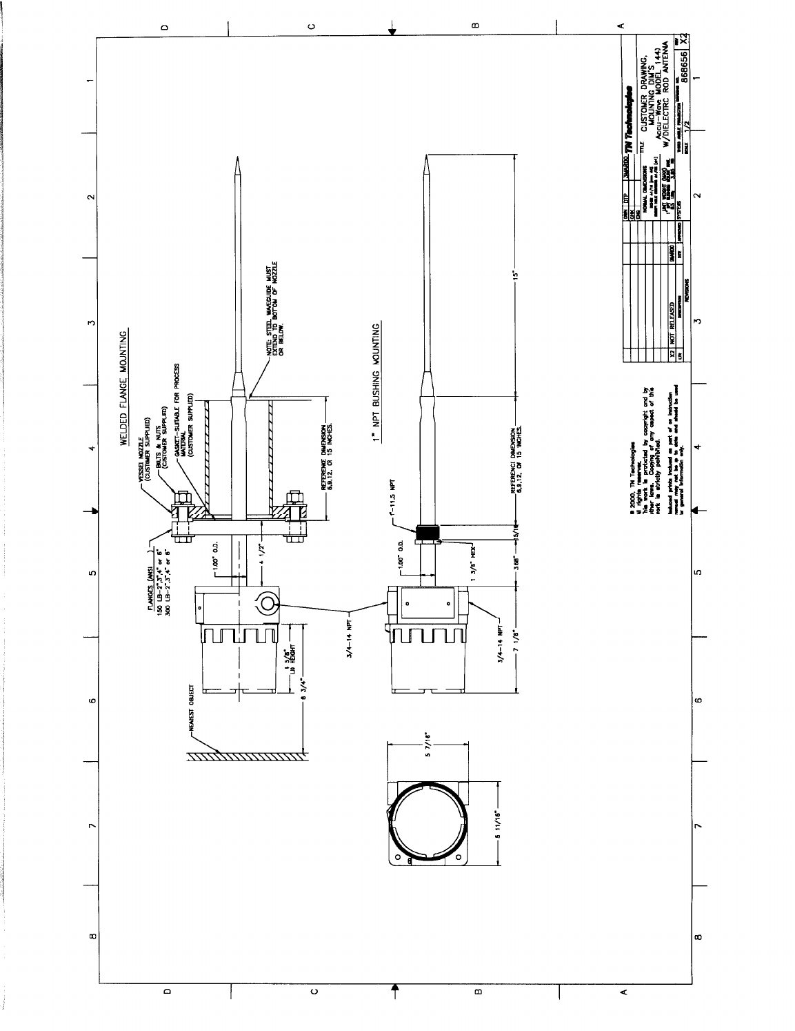
Dimensional Drawings
Refer to the appropriate drawings for the sensor mounting dimensions:
• Rod Antennas – refer to drawing 868656.
• Horn Antennas – refer to drawing TBD (future option).
Reduced-size copies of the drawings are provided in Appendix D.

Chapter 2 Hardware Installation Accu-Wave
2-4 TN Technologies
Mounting the Gauge
When mounting the gauge, ensure there are no obstructions between the antenna and the
surface of the process material. If obstructions cannot be avoided, refer to “False Echo
Management” in the Accu-Wave Operation Manual (717791).
Caution: Use proper lifting procedures to avoid injury.
Rod Antenna
1 Inch NPT Bushing Mounting
To mount a gauge with the 1 inch NPT bushing mounting option, simply screw the
threaded bushing into the corresponding fitting on the tank.
Note: Do not apply force to the housing to tighten the bushing. Use a wrench on
the hexagonal portion (1 3/8 in.) of the bushing.
Mount the gauge to the tank before attaching any wires or conduits.
Flange Mounting Instructions
You need the following (supplied by the customer):
1. 1 gasket suitable for the process material
2. 16 steel washers
3. 8 nuts and bolts
150 lb flange – use 5/8 inch hardware
300 lb flange – use 3/4 inch hardware
Refer to dimensional drawing 868656. Follow these steps to mount the gauge.
1. Center the gasket, suitable for your process material, on the nozzle flange.
2. Slide the antenna into the opening. Center the sensor flange on the gasket and
line up the bolt holes in the sensor flange and the nozzle flange.
3. Install the bolts and washers, and attach the nuts. Tighten the bolts in a star-
patterned sequence to equalize compression.

Accu-Wave Chapter 3 Wiring Procedures
TN Technologies 3-1
Chapter 3 Wiring Procedures
The Accu-Wave electronics includes the following boards.
• Main Electronics Board
• RS-232 daughter board (optional).
• Hart Communications daughter board (future option).
The required wiring steps are:
• connect 24 Vdc power supply to the gauge, and
• connect a remote computer terminal or Hand Held Terminal to the gauge via the
serial communication port.
Additional, optional wiring may include:
• 4-20 mA current output,
• contact closure input, or
• optional, remote display (2 line x 16 characters).
Caution: Remove all power from the unit before making any connections.
WARNING: All wiring must be done by qualified individuals in accordance with
applicable codes such as the NEC (National Electric Code) ANSI/NFPA
70 specifications or the Canadian Electrical Code Part 1.
Initial Wiring Preparations
Warning: Do not apply power to the unit in any hazardous area unless the safety
ground is properly wired inside the unit and the cover is properly
installed.
Hazardous Location Installations – The cable entries must be sealed
per the Installation Layout Drawing (868502).
Non-Hazardous Location Installations – The cable entries into the
enclosures must be sealed to prevent passage of gas or vapors. The
sealing compound should not be affected by the surrounding
atmosphere or liquids. The minimum thickness of the sealing
compound should be 5/8 in (16 mm).
If metal conduit is used, the conduit must be grounded.
Caution: Insulate the drain wire to eliminate ground loops.
Caution: CSA certified fittings must be used to maintain CSA rating for
enclosure.

Chapter 3 Wiring Procedures Accu-Wave
3-2 TN Technologies
Wiring Instructions
You will need a 1/8 inch bladed screwdriver to connect the wires to the plug-in
connector.
Refer to the Installation Layout drawing 868637 and Wiring diagram 868641. Follow all
notes on the drawings.
To wire the gauge:
1. Loosen the retaining screw at the base of the enclosure lid, then unscrew and
remove the enclosure lid.
2. Pull the cable(s) through the conduit opening(s) in the enclosure.
3. Connect the power cable ground to the internal ground on the bracket (the
bracket is grounded to the enclosure.
4. Remove the plug-in screw-terminal connector from the board. Loosen the
terminal screws. Insert the wires and make connections as shown in the
appropriate installation wiring diagram. Tighten the screws in the plug-in
connector to secure the wires. Replace the connector on the board when all wires
are secured.
5. Screw the enclosure lid back onto the housing and tighten the retaining screw.
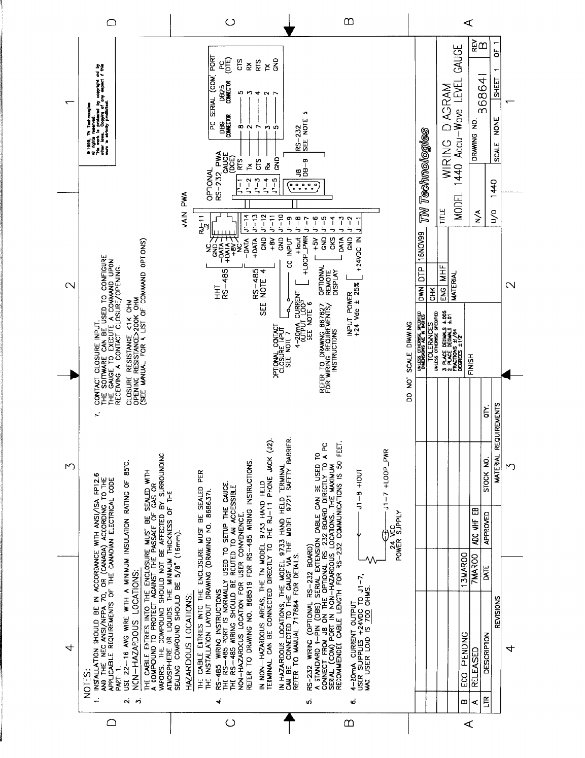
DC Power Wiring
The Accu-Wave is designed to operate on 24 Vdc ± 25%. The maximum input power
requirement is 12 W. As shown in this wiring diagram (868641), to connect DC power to
the main board:
1. Connect +24 Vdc to Pin 1 of the J1 connector, and
2. Connect the return for the +24 Vdc supply to Pin 2 of the J1 connector.
Note: To meet the requirements of CSA 1010.1, the input DC terminals shall be
supplied from an SELV (Safety Extra Low Voltage) source. In addition,
protective bonding (grounding) must always be provided.
4-20 mA Current Output
The current output range is programmable (refer to the Accu-Wave Operation Manual).
The maximum range is 0.4 to 20 mA and the default range is 4 to 20 mA.
Isolated, loop-powered, nominal voltage requirement is 24 Vdc for a 700 Ω load. As
indicated in the Wiring Diagram (868641), connect the +24 Vdc input to Pin 7 of the J1
connector on the main board.
Contact Closure Input
The contact switch input is dry contact input between ground and switch closed position.

Accu-Wave Chapter 3 Wiring Procedures
TN Technologies 3-3
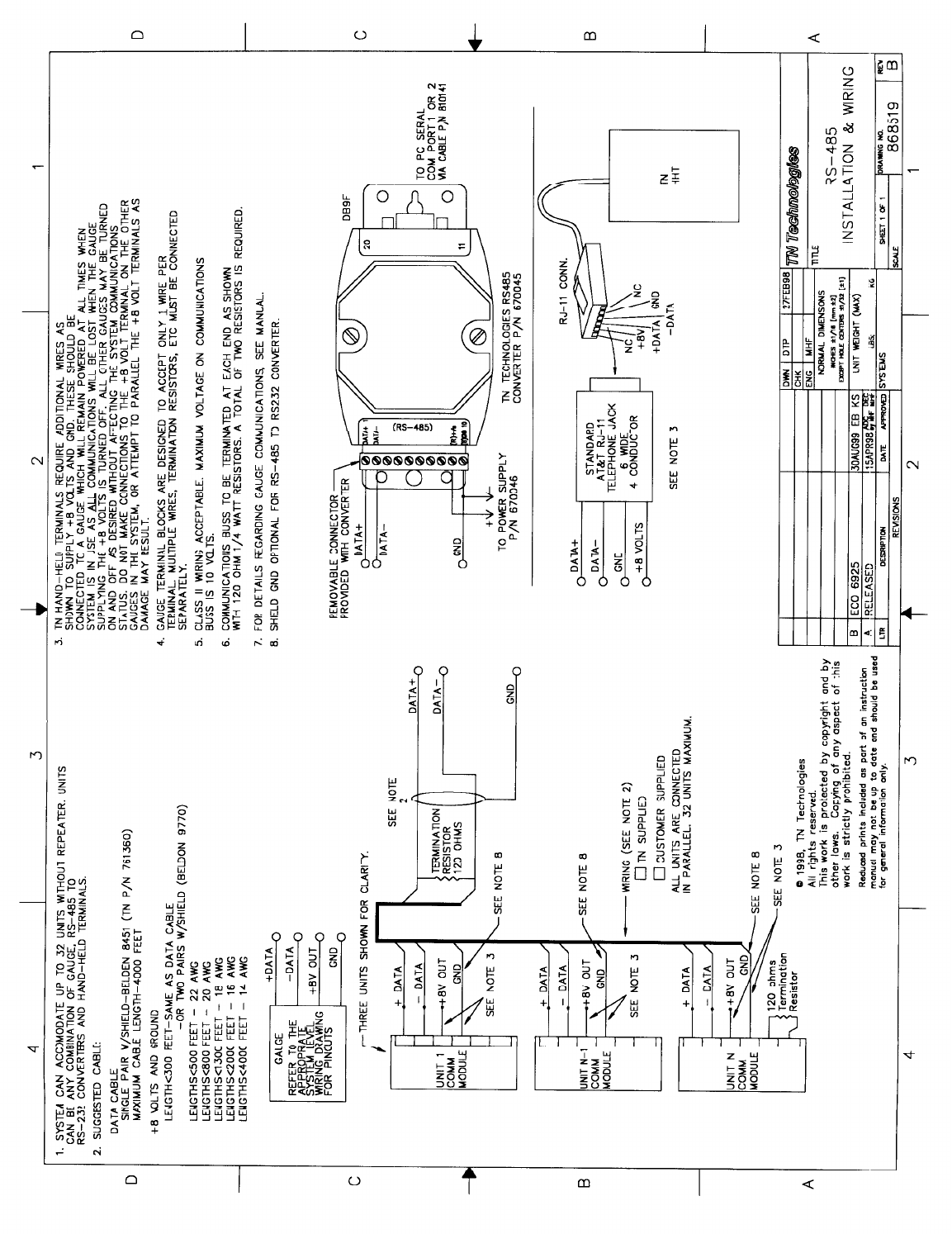
Serial Communications
The gauge provides an RS-485 multi–drop serial interface port. An RS-232 single–drop
is available with the optional RS-232 daughter board Both ports provide independent
access to the measurements and software functions. The ports can be used
simultaneously.
The RS-485 port can communicate with a PC running the Accu-Wave Setup Software, a
PC running a terminal emulation program, TN Technologies’ Hand-Held Terminal, ANSI
terminals, or VT100 terminals.
The RS-232 port can connect directly to a PC serial (COM) port using a serial cable.
Note: In order to communicate with a PC via the RS-485 port, an RS-485 to RS-
232 converter (TN part No. 885960) is required.

Accu-Wave Appendix A Returning Equipment for Service
TN Technologies A-1
Appendix A How to Return Equipment for Service
Call the TN Technical Services Department (Factory Service division) before returning
equipment for repair. Many problems can be diagnosed and resolved over the phone. For
after hours or weekend service, call our 24-hour Service number: 512-388-9320.
Please include the following information with all units returned for repair:
1. Specific information about the problem.
2. A point-of-contact name and phone number, in case we need more information.
3. A purchase order authorizing repairs, or a request for a quote.
4. Ship prepaid to the address below:
Factory Service Department
TN Technologies
2555 North IH 35
Round Rock, Texas 78664
The Receiving Department will not accept collect shipments.
Do not ship to our P. O. Box.

Accu-Wave Appendix B Parts List
TN Technologies B-1
Appendix B Parts List
Part No. Description
886639 Main Electronics Board
886641 RS-232 Daughter Board (option)
Windows Set-up Software (CDROM)
717790 Installation Manual
717791 Operation Manual
885960 RS-485 to RS-232 converter

Accu-Wave Appendix C Specifications
TN Technologies C-1
Appendix C Specifications
Operating Principle
Frequency modulated continuous wave (FMCW)
radar signal which measures distance; microprocessor
based transmitter computes level, volume and nine
other measurements.
Range
Up to 115 ft. (35 m.)
Reference Accuracy
±3 mm (1/8 in.)
Repeatability
±3 mm (1/8 in.)
Input Power
24 Vdc ±25%, 12 W
Serial Outputs & Inputs
RS-485 (Standard): Half duplex partyline
communication to a host computer or hand-held
terminal.
RS-232 (Optional): Full duplex communication with
a remote terminal, printer, PC or host computer.
Current Output
4 to 20 mA, isolated, loop-powered (24 Vdc).
Maximum load – 700 ohms. Compliant with
NAMUR 43 specification for fault current.
Contact Closure Input
1 contact closure input provided. (User provides
switch.)
Circuit Protection
Meets IEC 801-1,-2, and –3
Current output is isolated.
Microwave Emissions
In compliance with ANSI C95.1, “RF Field Exposure
Safety Guidelines”
Dimensions
Refer to Dimensional Drawings
Rod Antenna: D868217
Horn Antenna: TBD
Weight
Rod Antenna: ~15 lbs.
Horn Antenna: TBD.
Temperature Range (Electronics)
-40o C to +70oC (-40o F to +158o F)
Pressure
Rod Antenna
PP 600 psig. max.
PTFE 300 psig. max.
Exposed Materials (Process)
Rod Antenna
SS316 and Polypropylene, or
SS316, PTFE, and O-ring material.
Horn Antenna
TBD
Mounting
Rod Antenna
1 inch NPT bushing, or
Welded flange (150/300 lb.; 2, 3, 4, 6 inch )
Horn Antenna
TBD
Hazardous Location Approvals
FM
Class I, II, III, Division 1, Groups B, C, D, E, F, G
Class I, II, III, Division 2, Groups B, C, D, F, G
NEMA 4X
CSA
Class I, II, III, Division 1, Groups B, C, D, E, F, G
Class I, II, III, Division 2, Groups B, C, D, E, F, G
TYPE 4X
CENELEC
EEx d IIB + H2
Eex n IIB + H2

Accu-Wave Appendix D Drawings
TN Technologies D-1
Appendix D Installation Drawings
This Appendix contains reduced size copies of the drawings referenced in this manual.
The drawings are provided in the order listed below.