Thomson Broadcast and Multimedia 8BUSDA2500C 25 Watt Frequency Agile Digital Transmitter System User Manual 10 0007 ULPN drawer cover
Thomson Broadcast & Multimedia, Inc. 25 Watt Frequency Agile Digital Transmitter System 10 0007 ULPN drawer cover
Contents
- 1. SDA2500C Users Guide
- 2. Agile synthesizer drawer
Agile synthesizer drawer
1
All information contained in this document is confidential and proprietary to THOMCAST and shall not be disclosed without the prior written permission of THOMCAST.
CREATED: KAS ................................................................3/8/00 CHECKED: DMW............................................................. 3/9/00
RELEASED: name
............................................................ date
Document #: DOC10-0007
REV: FEB.23.00
Agile Synthesizer Drawer Technical Manual
COMWAVE DIVISION
Figure 1: Agile sythesizer drawer.
COMWAVE DIVISION
PRELIMINARY USER’S GUIDE
DOC33-0037
Agile Synthesizer Drawer
This is an unpublished work protected by United States copyright laws and is proprietary to Thomcast Communications, Inc.
Disclosure, copying, reproduction, merger, translation, modification, enhancement or use by anyone other than authorized
employees or licensees of Thomcast Communications, Inc. without the prior written consent of Thomcast Communications, Inc. is
prohibited.
Copyright (c) 2000 Thomcast Communications, Inc. All rights reserved
This copyright notice should not be construed as evidence of publication.

1
Warranty Information
COMWAVE DIVISION
All information contained in this document is confidential and proprietary to THOMCAST and shall not be disclosed without the prior written permission of THOMCAST.
Document #: DOC12-0001
REV: DEC.02.99
THOMCAST COMMUNICATIONS, COMWAVE DIVISION TWO YEAR
LIMITED WARRANTY
Thomcast warrants each product of its manufacture to be free from any defect in material and workmanship for a
period of two years after delivery to, and return by the original purchaser. No returns, however, will be accepted
unless accompanied by a written factory return authorization.
The limit of liability under this warranty shall be to repair or replace any product, or part thereof, which proves to be
defective after inspection by Thomcast with the exception of tubes, semiconductor devices, lamps, fuses or
equipment (i.e. modulators) manufactured by others, which are subject to only such loss adjustment as Thomcast
may obtain for the suppliers thereof.
This warranty shall not apply to any Thomcast product which has been modified, physically or electrically damaged,
or to modules which seals have been broken, or any product which has been subjected to conditions exceeding the
applicable specifications or ratings or improper service techniques.
Thomcast will not be liable for any direct or consequential injury, loss or damage incurred through the use, or the
inability to use, any Thomcast product.
Thomcast reserves the right to make design changes to any Thomcast product without incurring any obligation to
make the same changes to previously purchased units.
This warranty is the full extent of the obligation and liability assumed by Thomcast with respect to any and all
Thomcast products. Thomcast neither makes, nor authorizes any person to make, any other guarantee or warranty
concerning Thomcast products.

1
Agile Synthesizer Drawer Manual Table of Contents
COMWAVE DIVISION
All information contained in this document is confidential and proprietary to THOMCAST and shall not be disclosed without the prior written permission of THOMCAST.
CREATED: KAS................................................................3/8/00 CHECKED: DMW............................................................. 3/8/00
RELEASED:
......................................................................
Document #: DOC33-0037
REV: MAR.08.00
TABLE OF CONTENTS
TITLE DOCUMENT #
Cover Sheet...........................................................................................................................DOC10-0007
Warranty Information ...........................................................................................................DOC12-0001
SECTION 1
Provides information describing the system and how it works
Top Level Description ..........................................................................................................DOC13-0189
Block Diagram......................................................................................................................DOC15-0068
Specifications........................................................................................................................DOC19-0139
SECTION 2
Provides information to assist in setting up and turning on your system
Installation Procedure ...........................................................................................................DOC17-0030
External Interconnections .....................................................................................................DOC30-0044
Turn-On Procedure ...............................................................................................................DOC26-0053
SECTION 3
Provides information to help with troubleshooting
Troubleshooting
Equipment Fusing and Protection ..........................................................................DOC18-0076
Maintenance
Inspections and Cleaning........................................................................................DOC18-0002
Calibrations...........................................................................................................................DOC16-0058
SECTION 4
Provides information about individual segments of the system.
We recommend you contact Thomcast1 customer service when repairs are necessary.
Theory of Operation..............................................................................................................DOC14-0040
Front and Rear Panel Descriptions
Power Supply Board .............................................................................................................DOC13-0192
IF Linear Processor...............................................................................................................DOC13-0106
UHF Upconverter Module ....................................................................................................DOC13-0131
Microwave Synthesizer.........................................................................................................DOC13-0020
Precorrector Calibration Control Board................................................................................DOC13-0130
DC Block Module.................................................................................................................DOC13-0190
Amplifier Module .................................................................................................................DOC13-0057
SECTION 5
Provides contact & return information, as well available options.
Customer Service..................................................................................................................DOC20-0001
Return Packaging..................................................................................................................DOC20-0002
1 DOC20-0001 provides detailed contact information. International phone 001-570-474-6751, USA & Canada phone 1-800-266-9283.

1
Agile Synthesizer Drawer Top Level Description
COMWAVE DIVISION
All information contained in this document is confidential and proprietary to THOMCAST and shall not be disclosed without the prior written permission of THOMCAST.
CREATED: KAS ................................................................2/23/00 CHECKED: DMW............................................................. 2/28/00
RELEASED: name
............................................................ date
Document #: DOC13-0189
REV: FEB.23.00
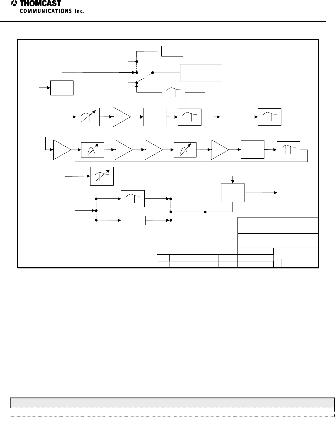
TOP LEVEL DESCRIPTION
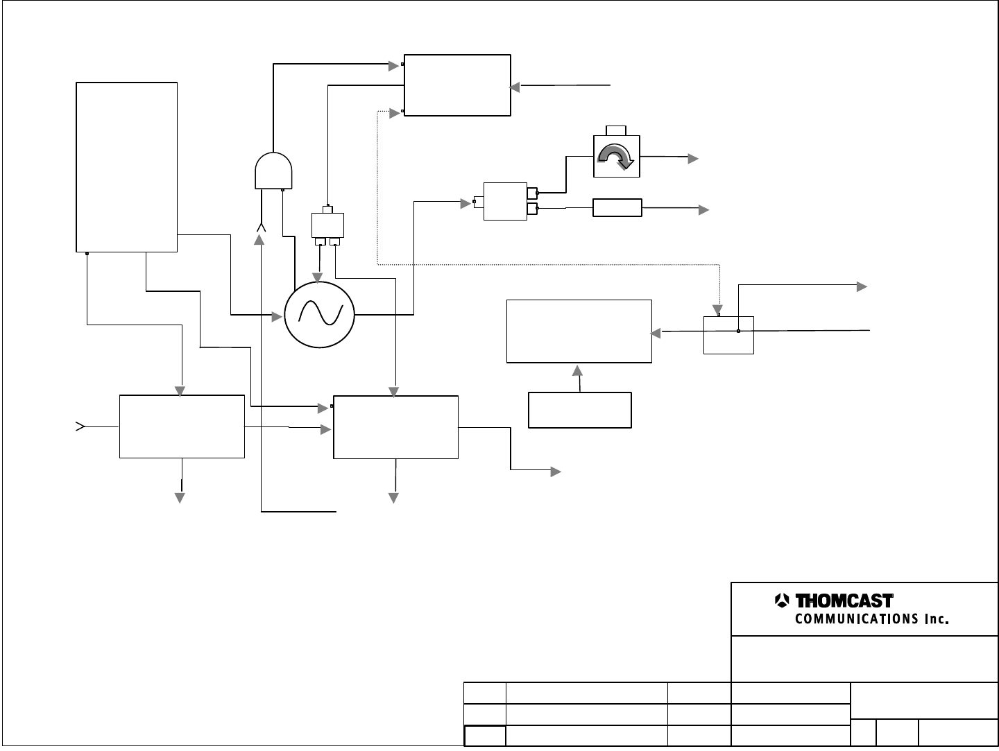
The agile synthesizer drawer is used in conjunction with an agile transmitter. It provides the main local oscillator to
the system. The synthesizer within is capable of being programmed to operate at the frequency necessary to achieve
the on-channel S-band carrier. The LO is heterodyned with an IF signal within the transmitter. This mixing action
determines what frequency the agile synthesizer drawer will be set at. Referring to the block diagram, which is
subsequent to this document, may provide a better understanding of how this drawer operates.
DRAWN:
RELEASED:
CHECKED:
DWG. NUMBER:
TITLE:
REV: P1
DOC15-0068
Block Diagram, Agile Synthesizer Drawer
KAS / 2-28-00
Name / date
REV Description
DMW / 2-28-00 Scale:
none Sheet
1of 1
COMWAVE DIVISION
ECO#
NAME/DATE
35-071-02
POWER
SUPPLY
BOARD
+12VOLT
SYNTHESIZER
09-075-2g60-02
34-015-02
E-PROM ASSEMBLY
THUMBWHEEL
SWITCH
33-338-02
DC INSERTER
Circulator
-5dB
DATA ‘Y’
ZA3PD-4 2 - 4 GHz
2-way splitter
15 pin D-SUB
(rear panel)
15 pin D-SUB
(rear panel)
-10 dB
LO Out (rear panel)
Freq. Reference In
(rear panel)
IF Input
(rear panel)
LO Sample (front panel)
CPU Interface
To Transmitter
Freq. Ref.
Phase Lock Indication
Ø Lock
05-070
IF LINEAR
PROCESSOR
09-062
IF TO UHF
UPCONVERTER
IF Detect
(rear panel)
Ø Lock (rear panel)
UHF Out (rear panel)
2-way
splitter

1
Agile Synthesizer Drawer Specifications
COMWAVE DIVISION
All information contained in this document is confidential and proprietary to THOMCAST and shall not be disclosed without the prior written permission of THOMCAST.
CREATED: KAS ................................................................3/8/00 CHECKED: DMW............................................................. 3/9/00
RELEASED: name
............................................................ date
Document #: DOC19-0139
REV: P1
SPECIFICATIONS SUBJECT TO CHANGE WITHOUT NOTICE
AGILE SYNTHESIZER DRAWER SPECIFICATIONS
PARAMETER SPECIFICATIONS
MICROWAVE LO
RF Output Level +5 ±2 dB
RF Output Frequency Range
Low Band
High Band 2.0 – 2.4 GHz
2.35 – 2.75 GHz
Reference Input Frequency 10 MHz (standard) accuracy 1 x 10⁻⁷ min
Reference Sensitivity 1 input at +1- dBm, +5 dB/-10 dB
Step Size 250 KHz
SSB Phase Noise (1 KHz res BW) (direct
measurement of LO) -80 dBc/Hz min @ 10 KHz offset
-100 dBc/Hz min @ 10 KHz offset
Spurious
0 to ±10 KHz
±10 KHz to ±50 KHz
±50 KHz to beyond
Below 1/f noise floor
-60 dBc or greater
-65 dBc or greater
Harmonics =-35 dBc
Output Power +5 ±2 dB
IF INPUT
Center Frequency 44 MHz
Bandwidth 5.5 MHz
Ultimate Out-of-Band Rejection1=45 dB
Input Signal 16 QAM, 64 QAM, 256 QAM, 8 VSB, 16 VSB or
analog standard M
Input Level -15 dBm average power typical
Input Return Loss 15 dB minimum
Frequency Response Correction 0 dB to ±1 dB typical
Frequency Response Temperature Stability ±0.25 dB typical
Group Delay Correction 0 ns to 25 ns minimum
Group Delay Temperature Stability ±2.5 ns typical
UHF OUTPUT
LO Range 300-400 MHz
Step Size 50 KHz
Spurious
0 to ±10 KHz
±10 KHz to ±100 KHz
±100 KHz to beyond
Below 1/f noise floor
=-60 dBc
=-65 dBc
SSB Phase Noise (direct measurement of LO) -100 dBc @ 10 KHz offset
UHF Out -18 dBm ±3 dB
Output Frequency Range2222 to 408 MHz
Harmonics =-60 dBc
Frequency Response Flatness
Bandwidth
Out-of-band
±.125 dB
10 – 12 MHz
-45 dB @ fc ±-35 MHz
LO Rejection =-60 dBc
Image Rejection (relative to input) =-60 dBc
1 Applies to the 05-070 and 05-074 modules only.
2 Other frequency options available.
2
Agile Synthesizer Drawer Specifications
COMWAVE DIVISION
All information contained in this document is confidential and proprietary to THOMCAST and shall not be disclosed without the prior written permission of THOMCAST.
CREATED: KAS ................................................................3/8/00 CHECKED: DMW............................................................. 3/9/00
RELEASED: name
............................................................ date
Document #: DOC19-0139
REV: P1
SPECIFICATIONS SUBJECT TO CHANGE WITHOUT NOTICE
PARAMETER SPECIFICATIONS
ALARMS & INDICATORS
µW Phase Lock
Alarm 3.30 VDC typical (across 10K O)
.290 VDC typical (across 10K O)
IF Detector Output Logic Level 0 VDC @ signal below threshold or +5VDC for
above
IF Detector Signal Level Threshold Adjustable from –20 dBm to –10 dBm
µW Phase Lock
Alarm 3.30 VDC typical (across 10K O)
.290 VDC typical (across 10K O)
GENERAL
Power Requirement 117/230 VAC, ±10%, 50/ 60 Hz (=0.1VA)
Supply Voltages +12 V
Connectors / Impedance
Input
J1 - Frequency Reference In
J2 – IF In
Output
J3 - UHF Out
J4 – LO Out
BNC / 50Ω
BNC / 75O
BNC / 50Ω
BNC / 75Ω
ENVIRONMENTAL
Operating Temperature -30°C to 50°C
Specified Temperature Range -13°C to 33°C
Relative Humidity 95% non-condensing
Dimensions 3.5” H x 19.0” W x 21.0” D
8.89 cm H x 48.26 cm W x 53.34 cm D
Approximate Shipping Weight 18.5 lb (8.38 kg)

1
Installation Procedure, Chassis
COMWAVE DIVISION
Document #: DOC17-0030
REV: FEB.22.00
All information contained in this document is confidential and proprietary to THOMCAST and shall not be disclosed without the prior written permission of THOMCAST.
CREATED: KAS................................................................ 5/24/99 CHECKED: PRC ...............................................................10/25/99
RELEASED: DMW
............................................................10/27/99
This is an unpublished work protected by United States copyright laws and is proprietary to Thomcast Communications, Inc. Disclosure,
copying, reproduction, merger, translation, modification, enhancement or use by anyone other than authorized employees or licensees of
Thomcast Communications, Inc. without the prior written consent of Thomcast Communications, Inc. is prohibited.
Copyright (c) 1999 Thomcast Communications, Inc. All rights reserved
This copyright notice should not be construed as evidence of publication.
PROCEDURE
DOC17-0030
Chassis Installation Procedure
COMWAVE DIVISION

2
Installation Procedure, Chassis
COMWAVE DIVISION
Document #: DOC17-0030
REV: FEB.22.00
All information contained in this document is confidential and proprietary to THOMCAST and shall not be disclosed without the prior written permission of THOMCAST.
CREATED: KAS................................................................ 5/24/99 CHECKED: PRC ...............................................................10/25/99
RELEASED: DMW
............................................................10/27/99
TABLE OF CONTENTS
STEP ONE: PACKAGE INSPECTION................................................................................................................................3
STEP TWO: UNPACK EQUIPMENT..................................................................................................................................3
STEP THREE: INSTALLING SLIDE RAILS.................................................................................................................... 4
STEP FOUR: RACK EQUIPMENT.......................................................................................................................................5
STEP FOUR: ENSURE PROPER ALIGNMENT.................................................................................................................6
STEP FIVE: CABLE EQUIPMENT......................................................................................................................................6
STEP SIX: SYSTEM TURN-ON.........................................................................................................................................6
STEP SEVEN: SAFETY.........................................................................................................................................................7
Figure 1: Rack, mounting rail...................................................................................................................................................4
Figure 2: Mounting slide rails...................................................................................................................................................5

3
Installation Procedure, Chassis
COMWAVE DIVISION
Document #: DOC17-0030
REV: FEB.22.00
All information contained in this document is confidential and proprietary to THOMCAST and shall not be disclosed without the prior written permission of THOMCAST.
CREATED: KAS................................................................ 5/24/99 CHECKED: PRC ...............................................................10/25/99
RELEASED: DMW
............................................................10/27/99
INSTALLATION INSTRUCTIONS
KEY: • = informational note
• Thomcast equipment operates in temperatures between –30° to 50° C (-22° to 122° F); the optimal operating temperature range is
13° to 33° C (55.4° to 91.4° F). Moderate temperatures generally extend equipment life.
• The equipment will operate with a relative humidity of up to 95% but it MUST be protected from conditions that cause
condensation.
STEP ONE: PACKAGE INSPECTION
Perform a thorough check of ALL parcels.
WHY HOW PROBLEMS
Ensure arrival of all packages without
damage.
1. Check the master packing slip to verify receipt of all
packages.
2. As shipment is received, inspect each package for
obvious damage.
If packages are missing
or damaged, inform the
freight carrier
immediately to file a
freight claim; then
notify a Thomcast
representative.1
STEP TWO: UNPACK EQUIPMENT
WHY HOW PROBLEMS
For placement in existing system.
1. Using a utility knife, open and unpack each box
separately.
2. Compare the contents with the packing slip and
inspect for in-transit damage.
Make note of any discrepancies or damages.
If there is a discrepancy
between the packing
slip and contents,
inform a Thomcast
representative1
immediately.
• Please recycle; however, do not discard all original packing material, save it at the equipment site to use when
returning items to Thomcast.
1 Detailed contact information is provided in this manual. International phone 001-570-474-6751, USA & Canada phone 1-
800-266-9283.
4
Installation Procedure, Chassis
COMWAVE DIVISION
Document #: DOC17-0030
REV: FEB.22.00
All information contained in this document is confidential and proprietary to THOMCAST and shall not be disclosed without the prior written permission of THOMCAST.
CREATED: KAS................................................................ 5/24/99 CHECKED: PRC ...............................................................10/25/99
RELEASED: DMW
............................................................10/27/99
STEP THREE: INSTALLING SLIDE RAILS
Typically slide rails are installed before shipping, if so, proceed to the next step.
WHY HOW PROBLEMS
Slide rails enable easy access to internal
adjustable controls and other
maintenance/adjustments.
Slide rails are packed and shipped with racks.
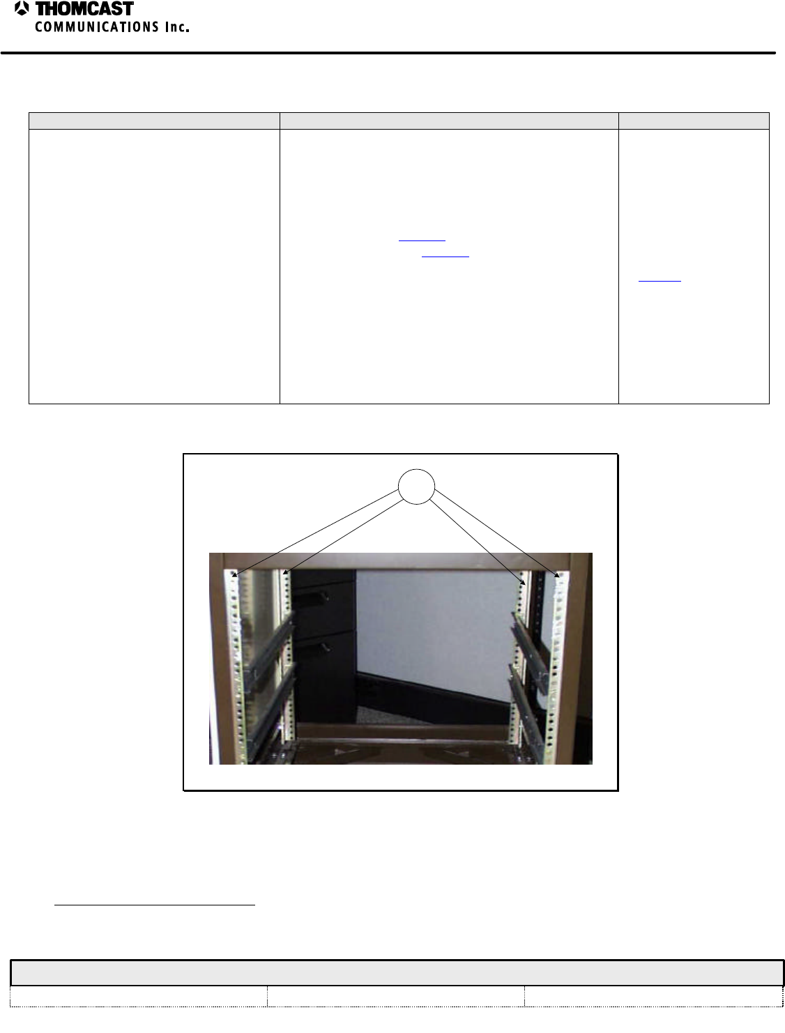
MOUNTING RAILS:
1. Using a #10 flat screwdriver, attach the slides to the
mounting rail1 within the rack with the provided
hardware. See Figure 1 for the location of the
mounting rail. See Figure 2 for directions on
mounting the rails.
2. Adjust rails if they don’t slide easily into the rack.
ADJUSTING RAIL-MOUNTING BRACKETS:
Loosen them and manipulate the drawer to seat rails to
match the rails on the drawer, once free sliding motion is
achieved retighten the brackets.
Contact a Thomcast
representative.2
1
Figure 1: Rack, mounting rail.
2 Detailed contact information is provided in this manual. International phone 001-570-474-6751, USA & Canada phone 1-
800-266-9283.

5
Installation Procedure, Chassis
COMWAVE DIVISION
Document #: DOC17-0030
REV: FEB.22.00
All information contained in this document is confidential and proprietary to THOMCAST and shall not be disclosed without the prior written permission of THOMCAST.
CREATED: KAS................................................................ 5/24/99 CHECKED: PRC ...............................................................10/25/99
RELEASED: DMW
............................................................10/27/99
Figure 2: Mounting slide rails.
STEP FOUR: RACK EQUIPMENT
This step is for racked equipment only. If equipment is used without a rack, position it and move on.
WHY HOW PROBLEMS
Proper positioning of the chassis in the
rack prevents damage. 1. Pull the rails out of the rack until they lock into
place.
2. Align the drawer until the rails mate.
3. Unlock the rails by depressing the lock button on
each rail while pushing the drawer in.
ë The drawer should slide easily into the rack;
if binding occurs, the rail-mounting
brackets need to be adjusted, see step six
“Adjusting Rail Mounting Brackets”.
Contact a Thomcast
representative.3
• Equipment MUST be placed in the rack prior to cabling.
• For spatial requirements refer to the specification sheet in section one of your manual.
3 Detailed contact information is provided in this manual. International phone 001-570-474-6751, USA & Canada phone 1-
800-266-9283.
6
Installation Procedure, Chassis
COMWAVE DIVISION
Document #: DOC17-0030
REV: FEB.22.00
All information contained in this document is confidential and proprietary to THOMCAST and shall not be disclosed without the prior written permission of THOMCAST.
CREATED: KAS................................................................ 5/24/99 CHECKED: PRC ...............................................................10/25/99
RELEASED: DMW
............................................................10/27/99
• In most cases, Thomcast provides a system equipment rack layout diagram that will assist in the proper installation and orientation of
equipment.
• If a rear door is used to secure the rack cabinet, forced ventilation through the cabinet is required (600 cfm minimum per transmitter is
recommended). An air or temperature interlock should be incorporated for protection against interruption of ventilation. The area should
be kept dry and clean.
STEP FIVE: ENSURE PROPER ALIGNMENT
WHY HOW PROBLEMS
Misalignment allows the front panels to
rub together, causing damage.
1. After racking drawers stand back and examine the
front panels.
2. If they do not rub against each other they are
properly aligned, proceed to the next step.
3. If they do rub against each other they are not
properly aligned, make the necessary readjustment
before moving on. Refer to step six, “Adjusting Rail
Mounting Brackets”, for instruction.
4. Repeat until aligned.
Contact a Thomcast
representative. 4
STEP FIVE: CABLE EQUIPMENT
WHY HOW PROBLEMS
System is not operational until accurate
external interconnections are completed. See the cabling information in this manual. Contact a Thomcast
representative.4
STEP SIX: SYSTEM TURN-ON
WHY HOW PROBLEMS
System operation. See the turn-on guide in this manual. Contact a Thomcast
representative.4
4 Detailed contact information is provided in this manual. International phone 001-570-474-6751, USA & Canada phone 1-
800-266-9283.

7
Installation Procedure, Chassis
COMWAVE DIVISION
Document #: DOC17-0030
REV: FEB.22.00
All information contained in this document is confidential and proprietary to THOMCAST and shall not be disclosed without the prior written permission of THOMCAST.
CREATED: KAS................................................................ 5/24/99 CHECKED: PRC ...............................................................10/25/99
RELEASED: DMW
............................................................10/27/99
STEP SEVEN: SAFETY
WHY HOW PROBLEMS
Protection for you and your system.
This is a very brief discussion of safety
issues, refer to DOC26-0031 for more
detail.
1. This equipment utilizes a grounding
plug on all power cords. For
personal safety, do not defeat this
safety feature.
2. As with similar types of equipment, high voltage can
be accessed when the chassis cover is removed.
Special care should be given in areas of fuses, line
switches, and power supplies.
3. Modern high power solid state equipment contain low
output voltage power supplies with very high current
capability. To prevent severe burns, avoid contact of
rings, watch bands, etc., with these circuits.
4. When servicing the transmission line and antenna, care
must be taken to avoid exposure to high energy
microwave.
Contact a Thomcast
representative.5
5 Detailed contact information is provided in this manual. International phone 001-570-474-6751, USA & Canada phone 1-
800-266-9283.
OPTIONAL AGILE CONTROLLER see the Agile Controller technical manual for more information regarding cabling
AGILE SYNTHESIZER DRAWER
AGILE TRANSMITTER
Freq Ref In
IF In
Transmit Antenna
AGILE SYNTHESIZER DRAWER
EXTERNAL INTERCONNECTIONS
COMWAVE DIVISION
Agile Synthesizer Drawer External Interconnections
All information contained in this document is confidential and proprietary to THOMCAST and shall not be disclosed without the prior written permission of THOMCAST.
CREATED: KAS 2/23/00 CHECKED: DMW 2-28-00 RELEASED: name date
Document #: DOC30-0044 REV: FEB.23.00 1
UHF Out
LO Out

1
COMWAVE DIVISION
All information contained in this document is confidential and proprietary to THOMCAST and shall not be disclosed without the prior written permission of THOMCAST.
CREATED: KAS ................................................................2/23/00 CHECKED: DMW............................................................. 2/28/00
RELEASED:
......................................................................
Document #: DOC26-0053
REV: FEB.23.00
Turn-On Procedure
TURN-ON PROCEDURE
This section explains the initial turn-on for your chassis and explains normal operation. Prior to equipment turn-on,
verify that all appropriate cabling has been accomplished.
Turn on
1. Ensure the rear mounted main power ON/OFF switch is in the OFF position.
2. Insert the power plug into a power outlet.
3. Position the main power switch to ON.
4. The front panel LED will continuously illuminate green verifying successful turn on and normal operation:
Operation
Selecting the proper operating channel, as discussed below, and having proper interconnections established between
this drawer and all accompanying chassis’ enables operation.
Channel Selection / Programming:
Channel selection is accomplished in two ways, manually or automatically. Both methods are described
below.
Manual Channel Selection
Manual channel selection is done through the use of the front panel thumbwheel switch. The thumbwheel
interfaces with and EPROM board sending a binary coded decimal (BCD) address to the firmware located
on the board. The EPROM logic then forwards programming information to the synthesizer in the same
manner. Typical programming results in selection of the lowest channel when the thumbwheel switch is
rotated to the [01] position. Progression allows channel selection to move upward in 6 MHz1 steps.
Agile Controller Interface
Upon connection of the Agile Controller, the manual channel setting is overridden. A data ‘Y’ is provided
on the DC insertion board. This allows a loop though of logic information in the drawer to the RF
precorrector module located in the upconverter plug-in module. The CPU interface sends a BCD address to
the EPROM board containing the channel selection of the transmitter to be backed up. The EPROM board
then forwards this programming to the synthesizer module.
1 Channel mapping of A1, B1, A2, B2 ….. G4 is typical, international standards are available.

1
Agile Synthesizer Drawer Troubleshooting Worksheet – 20-379-02
COMWAVE DIVISION
All information contained in this document is confidential and proprietary to THOMCAST and shall not be disclosed without the prior written permission of THOMCAST.
CREATED: AB ..................................................................3/8/00 CHECKED: KAS ...............................................................3/8/00
RELEASED:
.....................................................................
Document #: DOC18-0076
REV: MAR.08.00
TROUBLESHOOTING
The following lists explain various failure mode displays and possible solutions.
A 9-pin computer type diagnostic interface connector is located on the rear of the chassis to assist in
troubleshooting. IF detect, microwave phase lock, and UHF phase lock test points can be accessed/monitored at this
location.
• Repair of internal modules is not recommended or advised. Contact1 COMWAVE customer support should a failure occur.
Pin Function Checked
1Ground
2IF Detect
3Microwave Phase Lock
4UHF Phase Lock
1. Ground: for reference
2. IF Detect: high TLL = good; low TLL = bad.
Causes: Missing IF input.
Check for: Presence of IF input.
Remedy: Apply IF input.
3. µW Ø Lock: high TLL = good; low TLL = bad.
4. UHF Ø Lock: high TLL = good; low TLL = bad.
• If one phase lock has a low TLL indicating that it’s bad, contact Comwave for a replacement module.
If both phase locks are bad check the 10 MHz reference signal.
EQUIPMENT FUSING AND PROTECTION
One replaceable fuse2 is found in this chassis, see the table below
.Table 1: Transmitter fuse locations.
LOCATION REFERENCE VALUE
Rear Panel AC Input 1 amperes @ 230 VAC
1 DOC20-0001 provides detailed contact information. International phone 001-570-474-6751, USA & Canada phone 1-800-266-9283.
2 Replace only with the same type and rating.

1
Maintenance – Inspections and Cleaning
COMWAVE DIVISION
All information contained in this document is confidential and proprietary to THOMCAST and shall not be disclosed without the prior written permission of THOMCAST.
CREATED: KAS ............1/18/99 ECO #: 99-057, 6/14/99 CHECKED: DMW.............................................................1/18/99
RELEASED: PRC
............................................................. 1/18/99
Document #: DOC18-0002
REV: FEB.23.00
INSPECTIONS AND CLEANING
Thomcast products have been carefully designed to be maintenance free. Only periodic inspection1 and
cleaning is necessary.
INSPECTIONS
1) Inspect heat sinks and/or fans, if applicable, monthly for heavy accumulations of dirt and/or insects.
Heavy accumulation of foreign debris impedes cooling effectiveness and could lead to premature
failure.
2) If debris is found:
a) Shut down the transmitter/receiver
b) Unplug the AC line cord
c) Remove the top cover
d) Remove debris
3) After debris removal:
a) Replace the top cover
b) Plug the AC line cord in
c) Turn on the transmitter/receiver
d) Check the tightness of all cable connections
CLEANING
Clean the faceplate and outside cover using a damp non-abrasive cloth with a mixture of a mild detergent
and water.
1 If this is a component of a larger system, more in depth maintenance information may be included in the system manual, always
verify that ALL steps are followed.

1
Calibrations for the Agile Synthesizer Drawer – 20-379
COMWAVE DIVISION
All information contained in this document is confidential and proprietary to THOMCAST and shall not be disclosed without the prior written permission of THOMCAST.
CREATED: KAS ................................................................3/8/99 CHECKED: DMW............................................................. 3/8/99
RELEASED: name
............................................................ date
Document #: DOC16-0058
REV: MAR.08.00
CALIBRATIONS
SETTING THE MODULE FAULT INDICATOR THRESHOLD:
1) Ensure the proper input signal is applied.
2) Insert 4dB of attenuation in line with the incoming signal.
3) Adjust the corresponding IF detector potentiometer, via the front panel of the module until the DC voltage is on
the border line of being a logic high and a logic low; it is necessary to toggle the logic level between high and
low in order to reach the desired threshold.
4) Remove the 4dB of attenuation and ensure that the logic level remains high.

1
Agile Synthesizer Drawer Theory of Operation – 20-379
COMWAVE DIVISION
All information contained in this document is confidential and proprietary to THOMCAST and shall not be disclosed without the prior written permission of THOMCAST.
CREATED: KAS ................................................................3/8/00 CHECKED: DMW............................................................. 3/8/00
RELEASED: name
............................................................ date
Document #: DOC14-0040
REV: MAR.08.00
AGILE SYNTHESIZER DRAWER THEORY OF OPERATION
The drawer acts as the local oscillator in agile systems. It consists of a synthesizer, power supply, EPROM board,
precorrector board, DC inserter/power distribution board, circulator, and splitter.
It receives a 10 MHz frequency reference signal via the rear panel, which is used as the time base for phase locking
the internal synthesizer. The reference signal is routed through the DC inserter board and the signal is split and
amplified by hybrid amplifiers. A conditioned reference signal that contains a DC component containing
information about the phase lock status of the synthesizer is returned to the rear panel.
The reference signal is then superimposed onto a DC logic level; a logic high represents a phase locked condition,
while a logic low indicates an “out of lock state”1. A loop through allows the transmitter to utilize the reference
signal for other PLL circuits. Refer to the appropriate sections of the accompanying transmitter manual for detailed
information.2.
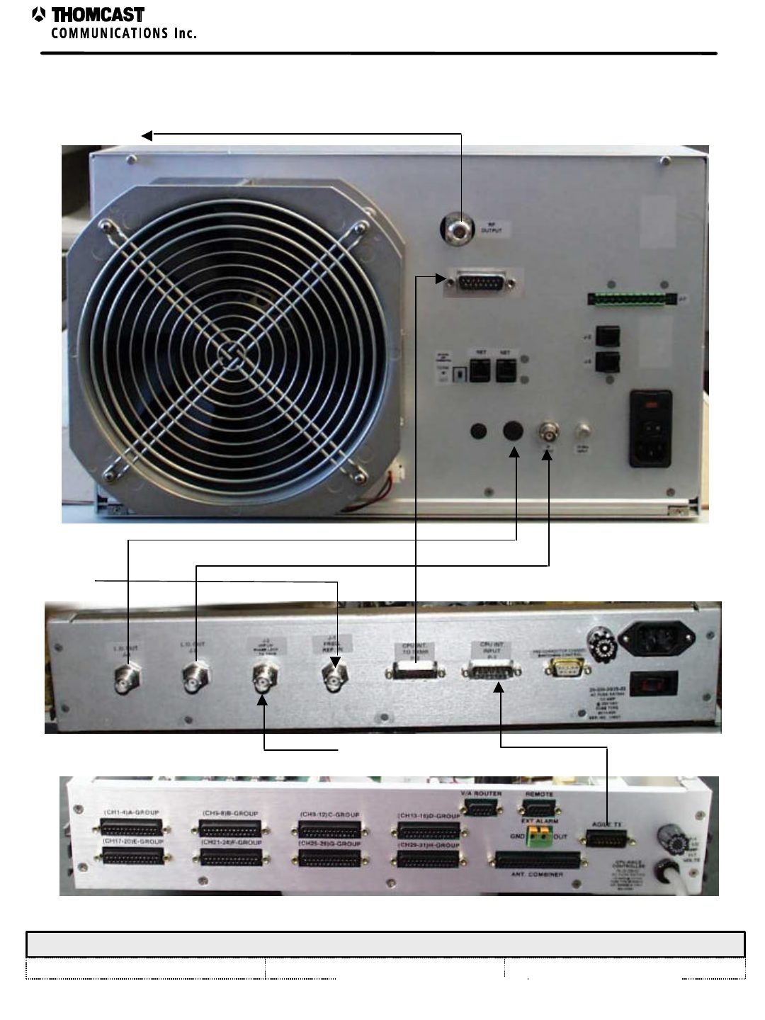
FRONT AND REAR PANEL DESCRIPTIONS
Front panel:
1. POWER INDICATOR LED: Signifies proper operation of the main DC power supply.
2. THUMBWHEEL SWITCH: Allows manual channel selection.
3. LO SAMPLE: BNC connector provides a test point for measuring the LO at a reduced power level.
• Terminate when not in use.
Rear panel:
1. J4 - LO OUT: BNC connector - output to transmitter; nominal -15 dBm level; use ¼” superflex cable for
interconnection.
2. J3 - UHF OUT: BNC connector - output to transmitter; nominal -15 dBm level; use RG58 50ohm type cable for
interconnection.
3. J2 – IF IN: BNC connector – input from modulator; nominal -15 dBm level; use RG59 75ohm type cable for
interconnection.
4. J1 – FREQ REF IN: BNC connector – input from reference drawer; 5 dBm ±5dB typical; use RG59 75ohm type cable
for interconnection.
5. P2 – CPU INTERFACE: 15 pin D-sub connector – output to transmitter.
6. P1 – CPU INTERFACE: 15 pin D-sub connector – input from Agile Controller.
7. FUSE HOLDER: Holds fuse for protection, see fusing section for fuse size.
8. AC ENTRY: AC interface, provides line filtering.
9. ON/OFF SWITCH: Interrupts AC power for service.
10. 9 PIN DIANOSTICS CONNECTOR.
1 Phase lock status is processed and displayed within the transmitter.
2 Manual sections describing DC block, UHF upconverter are recommended.
2
Agile Synthesizer Drawer Theory of Operation – 20-379
COMWAVE DIVISION
All information contained in this document is confidential and proprietary to THOMCAST and shall not be disclosed without the prior written permission of THOMCAST.
CREATED: KAS ................................................................3/8/00 CHECKED: DMW............................................................. 3/8/00
RELEASED: name
............................................................ date
Document #: DOC14-0040
REV: MAR.08.00
1 2 3
12310 78
4 5 6 9
FRONT PANEL
REAR PANEL
Figure 1: Front and rear panel.

1
Power Supply Board – 35-071
COMWAVE DIVISION
All information contained in this document is confidential and proprietary to THOMCAST and shall not be disclosed without the prior written permission of THOMCAST.
CREATED: DMW..............................................................3/8/00 CHECKED: KAS ...............................................................3/8/00
RELEASED: name
............................................................ date
Document #: DOC13-0192
REV: MAR.08.00
POWER SUPPLY BOARD
The linear power supply assembly (power supply) provides operating power for the synthesizer, IF linear processor,
and IF to UHF upconverter module and related diagnostic and communications functions in the chassis. The power
supply receives AC line voltage from the chassis rear panel receptacle. The AC line feed is fuse-protected.
Jumpers are used to select the nominal AC line voltage, 117 or 230 VAC. *Note: The AC line voltage is set at the
factory for a specific voltage and should not be changed by the end user. An MOV device is used to protect the
power supply from AC over voltage conditions.
Incoming AC is stepped down with a transformer; bridge rectified, and fed to a filter and regulator circuit to provide
an output voltage of 12 volts. The output voltage is available on power supply connector J1.
Table 1: DOC19-0142, REV P1.
Power Supply Specifications
Input Voltage 117 or 220 VAC
Positive Output Voltage +12 VDC ± 10%
Positive Output Current 1.5 Amp
Operating Temperature 0° C to 50° C
• SPECIFICATIONS ARE SUBJECT TO CHANGE WITHOUT NOTICE.
1
IF Linear Processor– 05-065, 05-070, 05-073, 05-074
COMWAVE DIVISION
All information contained in this document is confidential and proprietary to THOMCAST and shall not be disclosed without the prior written permission of THOMCAST.
CREATED: KAS ................................................................1/5/99 CHECKED: DMW............................................................. 12/7/99
RELEASED: PRC
............................................................. 12/7/99
Document #: DOC13-0106
REV: DEC.6.99
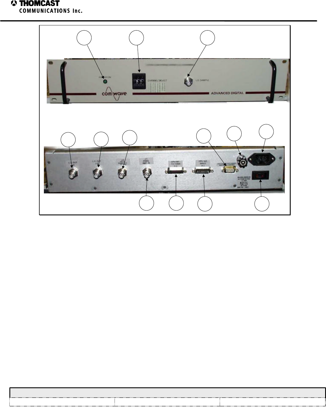
IF LINEAR PROCESSOR
The IF linear processor performs multiple functions among them are IF detection, frequency response compensation, &
group delay precorrection. It also provides for an optional saw filter stage, which can be added or bypassed through use
of jumpers. This module is used to correct linear distortion within the transmission system.
Once inside the incoming signal is split and
directed in two separate paths, one side of the
splitter is sent to a variable attenuator that
adjusts the signal level through the module the
other is sent to the detector stage. The input
attenuator provides approximately 15dB of
adjustment range. Through use of an external
microprocessor and automatic level control
can be achieved by varying the input
attenuator, this mode of operation can be
selected via the front panel of the module if
the system is so equipped. Each group delay
cell provides approximately ±10ns of delay.
These individual stages can be added as
needed to compensate any distortion up to
25ns within the system. Adding a stage is
accomplished by moving a pair of jumpers on
the processors main board. Refer to the
attached diagram for jumper configuration
information. Along with delay, the frequency
response of the system can be adjusted
through the frequency response network.
Figure 1: IF linear processor, 05-065-02 shown.
This network can provide ±.5 dB of frequency response compensation. This stage can be set to make up for a
frequency tilt in the system or can be set to counteract the roll-off encountered by the channel filter. Setting the overall
bandwidth of the stage is accomplished by adjusting the two variable inductors, which make up the tank circuit in each
frequency response cell. The gain of each frequency response cell is adjustable via the potentiometer on the front panel
of the module. The user is able to select the detection mode of the module. It is able to detect either the incoming
signal or the outgoing signal. The user must set the appropriate jumper on the main board. Regardless of the detection
mode the unused port must be terminated. The detector’s threshold must be calibrated via the front panel adjustment,
typically the signal level detector should indicate a module failure if signal is detected at –4dB lower than nominal
input. A TTL logic level is used to indicate module status, a logic high shows signal presence, while a logic low shows
low signal level. Another feature of the module is the auxiliary input, which allows a second carrier to be introduced, in
analog systems a secondary audio carrier maybe required. This auxiliary input is also adjustable to ensure proper
carrier ratio.
A final option is available normally used in digital systems; the saw filter is used to clean up out of band interference.
Typically used in agile transmission equipment this additional filtering stage reduces the side-lobe regeneration of the
incoming signal. In receiver applications it is used to eliminate undesired signals as a result of mixing. Refer to the
module’s block diagram for more detail.
2
IF Linear Processor– 05-065, 05-070, 05-073, 05-074
COMWAVE DIVISION
All information contained in this document is confidential and proprietary to THOMCAST and shall not be disclosed without the prior written permission of THOMCAST.
CREATED: KAS ................................................................1/5/99 CHECKED: DMW............................................................. 12/7/99
RELEASED: PRC
............................................................. 12/7/99
Document #: DOC13-0106
REV: DEC.6.99
DRAWN:
RELEASED:
CHECKED:
DWG. NUMBER:
TITLE:
REV: A
DOC15-0058
BLOCK DIAGRAM, IF LINEAR
PROCESSOR MODULE
KAS / 5-24-99
PRC / 12-7-99
REV Description
DMW / 12-7-99 Scale:
none Sheet
1of 1
COMWAVE DIVISION
ECO#
NAME/DATE
÷2
75O load
IF Detector
Group Delay
S
Filter
IF OUTPUT
SUB-CARRIER IN
IF IN
Group Delay
Group Delay
Figure 2: IF linear processor block diagram.

3
IF Linear Processor– 05-065, 05-070, 05-073, 05-074
COMWAVE DIVISION
All information contained in this document is confidential and proprietary to THOMCAST and shall not be disclosed without the prior written permission of THOMCAST.
CREATED: KAS ................................................................1/5/99 CHECKED: DMW............................................................. 12/7/99
RELEASED: PRC
............................................................. 12/7/99
Document #: DOC13-0106
REV: DEC.6.99
IF LINEAR PROCESSOR SPECIFICATIONS
Table 1: DOC19-0055, REV A
Parameter Specification
Center Frequency 44 MHz
Bandwidth 5.5 MHz
Ultimate Out-of-Band Rejection1≥ 45 dB
Input Signal 16QAM, 64QAM, 256QAM, 8VSB, or 16VSB or
analog standard M
Input Level -15 dBm average power typical
Input Return Loss 15 dB minimum
Impedance / Connector
Input
Output 75 O / Female SMA
75 O / Female SMA
Output Level -15 dBm average power typical
Output Return Loss 15 dB minimum
Gain 0 dB typical, adjustable from +4 dB to –10 dB
Frequency Response Correction 0 dB to ±1 dB typical
Frequency Response Temperature Stability ±0.25 dB typical
Group Delay Correction 0 ns to 25 ns minimum
Group Delay Temperature Stability ±2.5 ns typical
Detector Output Logic Level 0 VDC @ signal below threshold or +5 VDC for above
Detector Signal Level Threshold Adjustable from –20 dBm to –10 dBm
Power Supply Voltage +12 VDC ± 0.5 VDC
Current 400 mA typical; 500 mA max
Operating Temperature 0° to 50° C
• SPECIFICATIONS ARE SUBJECT TO CHANGE WITHOUT NOTICE
1 Applies to the 05-070 & 05-074 modules.
1
UHF Upconverter – 09-058, 09-059, 09-061, 09-062,
09-064, 09-065, 09-080
COMWAVE DIVISION
All information contained in this document is confidential and proprietary to THOMCAST and shall not be disclosed without the prior written permission of THOMCAST.
CREATED: KAS ................................................................2/15/99 CHECKED: DMW............................................................. 2/25/99
RELEASED: PRC
............................................................. 3/8/99
Document #: DOC13-0131
REV: MAR.08.00
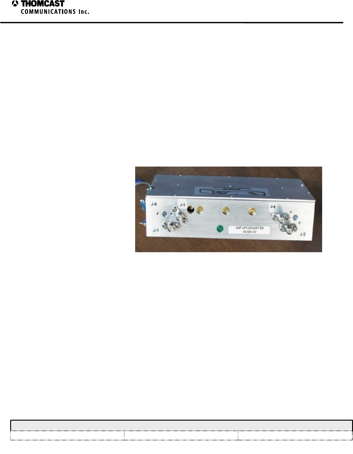
UHF UPCONVERTER
This module performs an upconversion from a TV IF to a 2nd IF at around 350 MHz. This second IF frequency,
when mixed with the LO, produces the desired microwave frequency. The second IF is necessary to make filtering
of the microwave LO and other undesired signals manageable in broadband agile systems. The visual and aural TV
IF’s are treated separately through the module, each chain providing the necessary filtering to get rid of the image
frequency and the UHF local oscillator. In the case of digital, the mixing / filtering stages of the aural chain are left
out. Features of the module include adjustable bandpass filters, LO notches, phase lock indication, LO sample, and
an adjustable aural carrier level.
UHF SYNTHESIZER
The UHF synthesizer board establishes the final output frequency operation of the module. The synthesizer operates
as the local oscillator within the unit. It contains a voltage controlled oscillator (VCO) phase locked to a high
stability reference source (10 MHz) achieving a precise output frequency. This signal is heterodyned (mixed) with
an intermediate frequency (IF), typically 44 MHz center, to produce the modules output carriers. When the IF is
mixed with the LO a sum and difference product will result.
The functionality of the synthesizer
can be explained starting with the
reference input. To achieve 400
KHz, a programmed PAL divides the
10 MHz source by 25. The 400 KHz
signal forms the reference to the
synthesizer IC. Internal to the IC is a
programmable divider, which further
divides the reference signal, making
the reference frequency 50 KHz. The
synthesizer is a control loop that is
continuously monitoring the
frequency status of the VCO. Figure 1: 09-080-02 UHF upconverter module.
Beginning at the VCO, upon turn on, an unknown frequency is coupled to a dual modulous prescaler that divides the
incoming frequency by either 64 or 65 depending on the logic level of the modulous control line at that instant in
time. Internal to the synthesizer IC there are two divider stages, called “N” & “A”. These dividers are programmed
to achieve the desired output frequency of the synthesizer.
In an ideal locked condition, both phase detector inputs will equal 50 KHz. If the frequency arriving from the dual
modulous prescaler happens to be higher or lower than the reference port of the phase detector, an error voltage is
generated by the integrator to pull the VCO back to the desired frequency. The integrator works by comparing
energy levels caused by a change in duty cycle on its inputs. Following the integrator stage is a passive low pass
filter; added to further reduce the reference spurs. Eliminating reference noise before it reaches the VCO is vital.
The sharp pulses generated by the synthesizer IC can cause unwanted spurious products.
THREE POLE UPCONVERTER STAGE
This stage is responsible for translating the TV IF frequency to a 2nd IF at around 350 MHz as stated above. The IF
enters the module, it then passes through a lowpass filter stage, then to the mixer. Once the IF and LO are
heterodyned, the undesired signals must be filtered. This is accomplished with a three pole filter designed to reject
the LO and image frequency. A notch is incorporated to further reject the LO

2
UHF Upconverter – 09-058, 09-059, 09-061, 09-062,
09-064, 09-065, 09-080
COMWAVE DIVISION
All information contained in this document is confidential and proprietary to THOMCAST and shall not be disclosed without the prior written permission of THOMCAST.
CREATED: KAS ................................................................2/15/99 CHECKED: DMW............................................................. 2/25/99
RELEASED: PRC
............................................................. 3/8/99
Document #: DOC13-0131
REV: MAR.08.00
TWO POLE UPCONVERTER STAGE (ANALOG ONLY)
This stage is similar to the three pole section. Differences in the two include a much narrower bandpass filter
intended only for passing the aural carrier. Additionally, the aural carrier may be adjusted in level to set the carrier
ratio in analog applications.

1
Microwave Synthesizer – 09-049 series including 09-056 & 09-070,
Agile – 09-052 & 09-066; 09-073 series including 09-074, & 09-078,
Agile – 09-075 & 09-079; 09-092, 09-093, 09-097, & 09-098
COMWAVE DIVISION
All information contained in this document is confidential and proprietary to THOMCAST and shall not be disclosed without the prior written permission of THOMCAST.
CREATED: KAS ................................................................6/3/98 CHECKED: IH..................................................................9/12/98
RELEASED: PRC
............................................................. 10/29/98
Document #: DOC13-0020
REV: NOV.08.99
ECO #: 99-057
MICROWAVE SYNTHESIZER
The microwave synthesizer module determines the microwave upconverter mixer input and transmitter output
operating frequency. The operating frequency is determined by programming of the phase locked loop frequency
synthesizer. Agile transmitter programming information is sent via an eprom board, there are no DIP switches.
Miniature DIP switches SW1 and SW2 set N counter and A counter PLL programming inputs. A 10 MHz input
reference signal applied to J1 determines the frequency stability of the PLL.
The synthesizer module uses a microwave prescaler, dual modulus prescaler, and internal dividers to reduce the 10
MHz reference and microwave voltage controlled oscillator (VCO) frequencies to 25 kHz for the 09-049 series and
09-093 version; 125 KHz for the 09-073 series, 09-097 & 09-098 versions; or 200 KHz for the 09-092 version.
These signals are applied to separate inputs of a phase detector. Input signals of equal phase generate no change in
output. Should the VCO deviate in frequency, a phase shift is detected causing an integrator/low pass filter to
generate a DC control voltage proportional to the offset frequency. This control voltage is applied to the microwave
VCO to return it to the selected frequency.
The microwave local oscillator frequency is derived by adding (or subtracting in certain cases) the desired
transmitter channel frequency to the incoming IF frequency:
EXAMPLE: Visual Output Frequency +Visual IF =Microwave LO Frequency
2501.25 MHz +45.75 MHz =2547 MHz
Aural Output Frequency +Aural IF =Microwave LO Frequency
2505.75 MHz +41.25 MHz =2547 MHz
Figure 1: Fixed channel synthesizer, 09-073 version.

2
Microwave Synthesizer – 09-049 series including 09-056 & 09-070,
Agile – 09-052 & 09-066; 09-073 series including 09-074, & 09-078,
Agile – 09-075 & 09-079; 09-092, 09-093, 09-097, & 09-098
COMWAVE DIVISION
All information contained in this document is confidential and proprietary to THOMCAST and shall not be disclosed without the prior written permission of THOMCAST.
CREATED: KAS ................................................................6/3/98 CHECKED: IH..................................................................9/12/98
RELEASED: PRC
............................................................. 10/29/98
Document #: DOC13-0020
REV: NOV.08.99
ECO #: 99-057
Table 1: DOC19-0034, REV C.
Parameter Specification
VCO P/Ns
09-092, 09-093, 09-097, & 09-098 versions only V803SE01, V604SC01
CFO-S-Axx (xx = number which varies with frequency)
Reference Input Frequency 10 MHz (Standard) accuracy 1 x 10 -7 min
RF Output Frequency Range
09-092, 09-093, 09-097, & 09-098 Low Band: 2.0 - 2.4 GHz, High Band: 2.35 - 2.75 GHz
2.0 – 2.9 GHz
Reference Sensitivity 1 input at +10 dBm, +5 dB/-10dB
RF Output Level 4 outputs at +9 dBm, ±2 dB
Step Size
09-049 series & 09-093
09-073 series, 09-097, & 09-098
09-092
50 KHz
250 KHz
2 MHz
Output Impedance 4 outputs at 50 O
NOTE: All unused ports must be terminated
Isolation Between Ports
J2-J3: > 25 dB
J2-J4: > 35 dB
J2-J5: > 35 dB
J3-J5: > 35 dB
J3-J4: > 35 dB
J4-J5: > 25 dB
SSB Phase Noise (1 KHz Res BW)
09-092, 09-093, 09-097, & 09-098 only
(direct measurement of microwave LO)
-80 dBc/Hz min @ 10 KHz offset
-100 dBc/Hz min @ 10 KHz offset
Spurious 0 to +10 KHz below 1/ƒ noise floor
+10 KHz to +50 KHz -60 dBc or greater
+50 KHz to beyond -65 dBc or greater
Harmonics =-35 dBc
Phase Lock Indication
Locked state
Unlocked state 3.30 VDC typical (across 10K O)
.290 VDC typical (across 10K O)
Power Supply Requirements +12 VDC + .5v
+12 VDC 450 mA typical
+12.5 VDC 750 mA typical
Operating Temperature -30 to +50° C
• SPECIFICATIONS ARE SUBJECT TO CHANGE WITHOUT NOTICE.

1
Precorrector Calibration Control Board – 34-015
COMWAVE DIVISION
All information contained in this document is confidential and proprietary to THOMCAST and shall not be disclosed without the prior written permission of THOMCAST.
CREATED: KAS ................................................................4/20/99 CHECKED: DMW............................................................. 4/20/99
RELEASED: CPU
............................................................. 4/20/99
Document #: DOC13-0130
REV: FEB.23.00
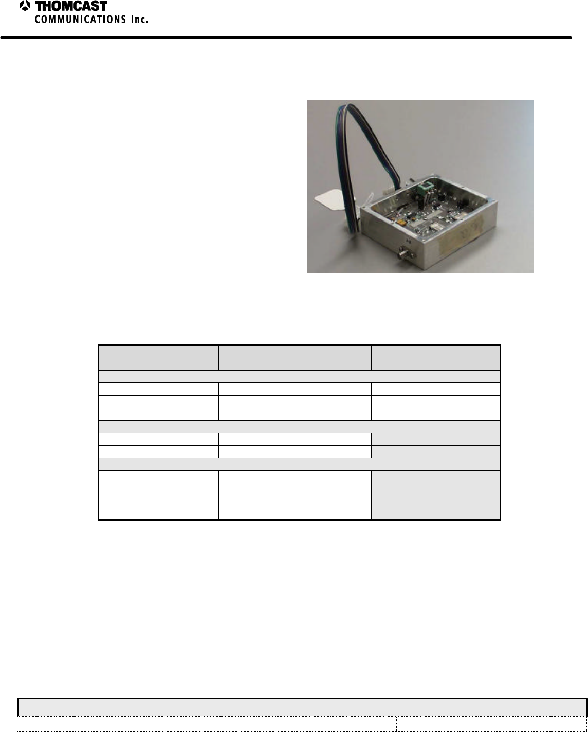
PRECORRECTOR CALIBRATION CONTROL BOARD
This board provides control of a frequency synthesizer and
an RF precorrector. It is typically used in frequency agile
equipment. This board may be used to replace various types
of Thomcast EPROM boards.
It contains an MC68HC711E9 MCU running a firmware
program. The program directs the MCU to set the frequency
synthesizer control data on output connector P4 and to output
the precorrector analog control voltages on P7 and/or P8. In
general, the synthesizer control data and precorrector analog
control voltages will be unique for each broadcast channel
available to the agile equipment. Therefore, the MCU needs
to be aware of the channel that has been selected for the agile
equipment. Channel selection is provided as BCD words on
P1/P2 and/or P3. The MCU reads the BCD words and
provides the channel-specific outputs accordingly.
Connectors P1 and P2 are board logic inputs that are
typically harnessed to the thumbwheel channel selection
switches on the front panel or top cover of the agile
equipment. When the user sets the agile equipment to
operate on a given channel, say channel 18, a combination of
logic ones and zeroes is provided on connectors P1 and P2
such that the MCU reads BCD ‘18’ (binary 0001 1000).
In cases where a Thomcast Frequency Agile Transmitter
Control/Monitor system (Agile Controller) is be connected to
the agile equipment to determine the agile channel in the case
of a system fault, the frequency selection data is input to the
board on connector P5. When the Agile Controller interface
is connected to P5, P5-5 and P5-6 are grounded, causing
switch ICs U4 and U5 to take the frequency selection data
from P5 and to apply it to the MCU inputs, while
disconnecting the thumbwheel switches. The MCU then
selects the appropriate synthesizer control data from its
internal memory and sends the data to the synthesizer. Figure 1: 34-015-02 board.
Precorrector control voltages are typically unique for a channel and are selected for output in the manner described
above for the synthesizer control. For a given channel, the MCU recalls stored control data for each precorrector
control circuit. The control data for each circuit is written to IC U8, a serial-input 8-channel 8-bit DAC. The MCU
writes the unique control data to each DAC channel, causing analog voltages to be driven out of U8. The analog
voltages are buffered and/or scaled using individual sections of op-amp ICs U9 and U10. Where greater drive
capability is required, transistors Q1 and Q2 are used.
Connector P9 and IC U7 provide an RS-232 interface for the board. During factory configuration and testing of the
agile equipment, a computer is interfaced to the board. The channel-specific synthesizer control data and
precorrector control data is entered by a technician and stored in the MCU’s internal EEPROM. This data is non-
volatile and is not lost when power is removed. Any of the synthesizer or precorrector data may be changed as
desired by connecting the PC and running the setup program.
1
DC Block Module
COMWAVE DIVISION
All information contained in this document is confidential and proprietary to THOMCAST and shall not be disclosed without the prior written permission of THOMCAST.
CREATED: SS...................................................................4/28/97 CHECKED: JS ..................................................................4/28/97
RELEASED: DMW
........................................................... 4/28/97
Document #: DOC13-0190
REV: FEB.23.00
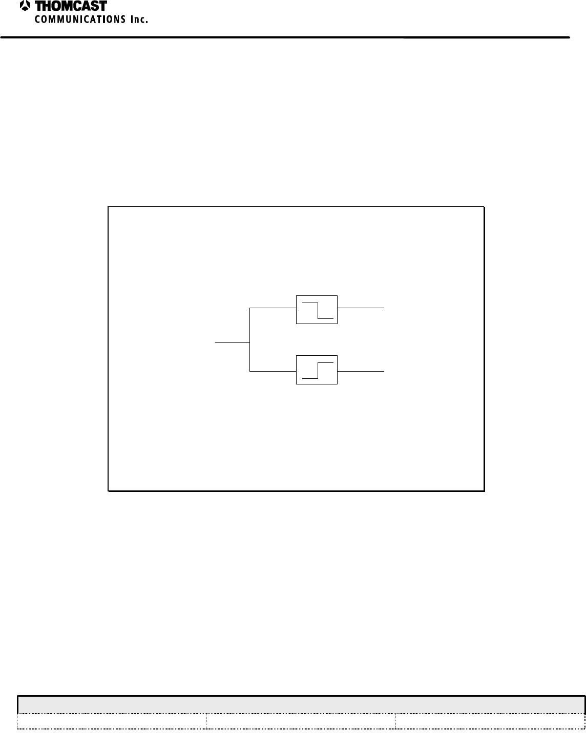
DC BLOCK MODULE
The DC block module receives at its input a low frequency RF signal that is superimposed on a DC logic level. The
RF signal is utilized as a frequency reference that provides a means of phase locking PLO’s (phase locked oscillator)
within the transmitter. The DC logic reports the phase lock status of the main LO, which is located external to the
transmitter.
The input signal applied to J1 passes through a coupling capacitor that serves as a block to the DC component and
secondly as a high pass filter to the RF signal. The conditioned reference signal arrives at J2. The input signal also
passes through a filter where the reference signal is stripped via a low pass circuit. The resulting DC voltage is
available via a feedthru for monitoring purposes, see figure 1.
J1
J2
FEEDTHRU
COMBINED FREQ
REFERENCE AND
DC LEVEL
DC LEVEL
FREQUENCY
REFERENCE
Figure 1: DC Block module block diagram.
1
Amplifier with ALC – 04-305(agile), 04-314
COMWAVE DIVISION
All information contained in this document is confidential and proprietary to THOMCAST and shall not be disclosed without the prior written permission of THOMCAST.
CREATED: AAC................................................................9/1/98 CHECKED: DMW.............................................................10/20/98
RELEASED: PRC
............................................................. 10/20/98
Document #: DOC13-0057
REV: FEB.23.00
AMPLIFIER WITH ALC
The ALC modules for the local oscillator are broadband
output level controlled modules with a dynamic range of
P1dB=+21dBm based on MMIC technology devices.
These blocks have a gain range from 5 to 14dB and are
fed by a +12V power supply at .4A maximum current.
Access for the RF signal is made by means of J1 and J2
respectively input and output. Distinct controls are
available for both manual and automatic modes, which
can be set by means of an external switch.
Figure 1: 04-314-02 ALC module.
Table 1: DOC19-0028, REV B.
PARAMETER SPECIFICATION NOTES/TEST
CONDITIONS
RF (04-308/04-314)
Input Return Loss -15 dB typical, -12 maximum 2.0 GHz to 2.7 GHz
Gain 5 to 14 dB typical 2.0 GHz to 2.7 GHz
Total Flatness 0.5 dB typical, 1 maximum 2.0 GHz to 2.7 GHz
DC (04-305/04-314)
Power Supply 12 V
Current 400 mA maximum
GENERAL
Impedance / Connector
Input
Output 50 O / Female SMA
50 O / Female SMA
Operating Temperature 0° C to 50° C
• SPECIFICATIONS ARE SUBJECT TO CHANGE WITHOUT NOTICE.
1
Customer Service
COMWAVE DIVISION
All information contained in this document is confidential and proprietary to THOMCAST and shall not be disclosed without the prior written permission of THOMCAST.
CREATED: KAS ............5/6/99 ECO #: 99-035, 3/25/99 CHECKED: DMW..............................................................1/18/99 RELEASED: PRC .............................................................. 1/18/99
Document #: DOC20-0001
REV: FEB.09.00
CUSTOMER SERVICE
CONTACT INFORMATION
DURING BUSINESS HOURS
Inquiries may be directed to Thomcast Communications, Comwave Division during business hours, 8 am to 5
pm Monday through Friday. When the automated attendant answers you will be given the option of dialing
your party direct or speaking with the operator.
AFTER BUSINESS HOURS
If you need emergency assistance due to equipment shutdown or malfunction, customer support personnel are
available 24 hours a day. Call Comwave at one of the numbers listed below; when the automated attendant
answers press 6, leave your name, company name, phone number, equipment model number(s), and a brief
description of the problem you’re encountering. When you hang up the system will automatically page the on-
call technician who will then return your call in a timely manner. You can listen to the message prompt for
other options as well, however, for emergency assistance you MUST use option 6.
Thomcast Communications, Comwave Division
Crestwood Industrial Park, 395 Oakhill Road
Mountaintop, PA 18707
1-800-266-9283 USA & Canada
1-570-474-6751 International1 & USA
(Please note, as of 12/98, our area code changed from 717 to 570)
1-570-474-5469 FAX
(Please note, as of 12/98, our area code changed from 717 to 570)
COMMENTS/SUGGESTIONS
Please forward comments regarding documentation content and/or layout, or suggestions to improve Comwave
publications to ksimeone@thomcastcom.com.
EQUIPMENT RETURNS
If the equipment requires return for factory service, please follow the guidelines listed. Thomcast cannot be
held responsible for damaged equipment received due to improper packing; contact Thomcast with any
questions or concerns.
1. Contact Comwave: Call Comwave to report the problem and to obtain a “Return Authorization”
number2 (RA). This enables accurate tracking and identity of returned equipment for prompt and efficient
service.
2. Obtain packaging materials: Use original boxes and packing materials when returning any equipment.
This will safeguard against most in-transit damages. If original boxes and packing materials are not available,
contact Thomcast to obtain replacement materials prior to shipping, they are provided at a nominal cost.
3. Pack equipment: Use original packing materials and directions provided. Most equipment is packed in a
box within another box; this varies with each product. Double boxing provides maximum protection.
Caution: Do not pack equipment using “PEANUTS” as filler it does NOT provide sufficient protection
during shipping. Rough handling by the carrier may cause permanent damage to the equipment.
Thomcast cannot be held responsible for damaged equipment received due to improper packing.
1 International calls must dial the country code before the phone number, i.e. 001-570-474-6751.
2 If you do not obtain an RA number prior to returning equipment Thomcast cannot be held responsible for delays in repair and return
time.
1
Return Packaging
COMWAVE DIVISION
All information contained in this document is confidential and proprietary to THOMCAST and shall not be disclosed without the prior written permission of THOMCAST.
CREATED: KAS............ 1/18/99 ECO #: 99-035, 3/25/99 CHECKED: DMW............................................................. 1/18/99
RELEASED: PRC
..............................................................1/18/99
Document #: DOC20-0002
REV: DEC.08.99
RETURN PACKAGING
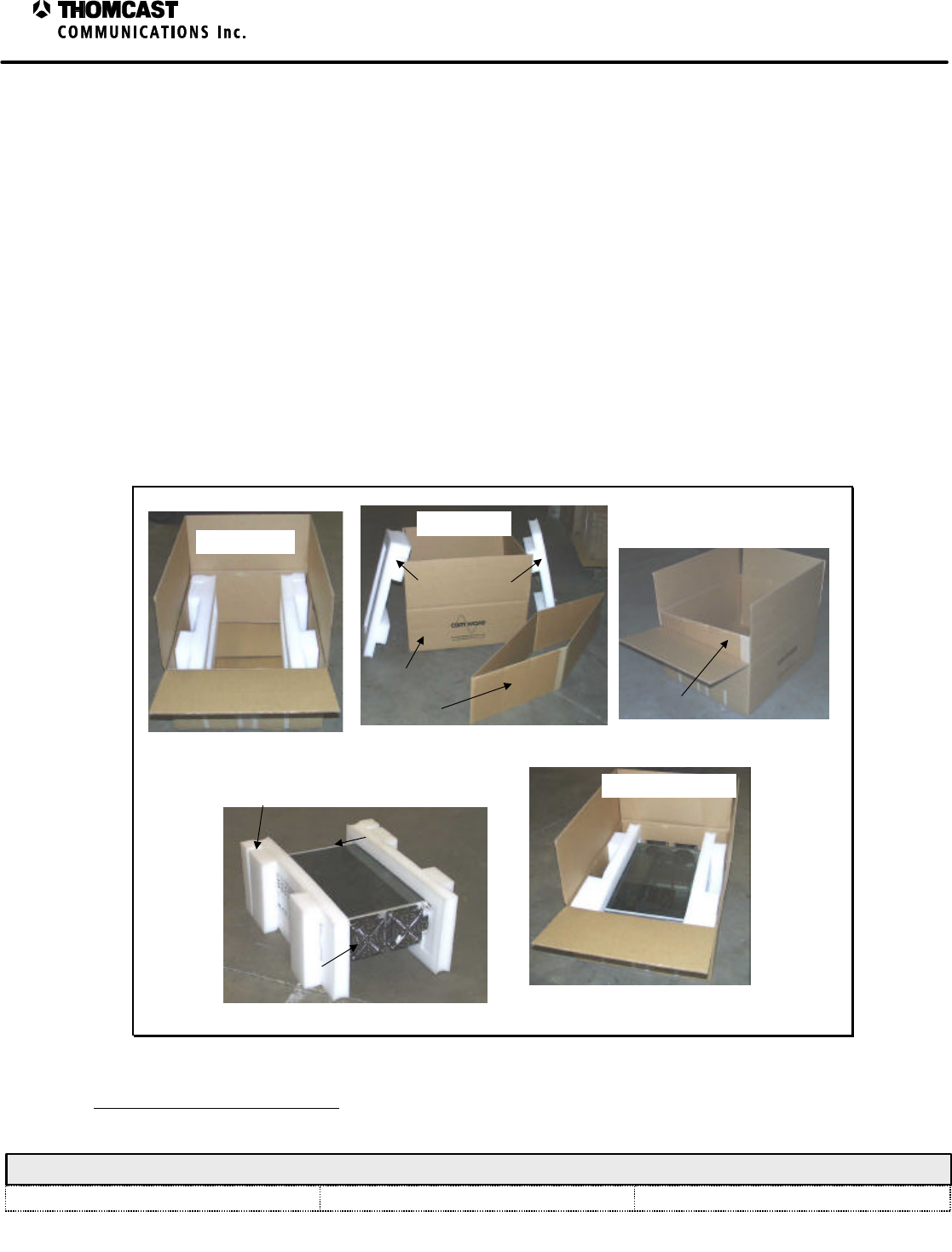
Below is a pictorial view of the following steps.
1) Begin with an empty Thomcast box, if you don’t have one please inform customer service when you contact
them for a return authorization (RA) number, which you MUST do prior to returning ANY equipment. NOTE:
A box consists of 4 parts, one cardboard box, one cardboard tube, and two polyethylene endcaps.
a) To assemble a flattened box put three1 layers of 2” clear box tape over the bottom seam, then position four
pieces of fiberglass strapping tape over the edges.
2) Put the cardboard tube in the box.
3) Place the polyethylene endcaps against the sides of the equipment. NOTE the front panel fits snuggly into a
slotted opening in the endcap.
4) Put the chassis in the box.
5) Close the box and seal the top seam with three layers of 2” clear box tape, then position four pieces of fiberglass
strapping tape over the edges.
6) Affix a shipping label to the box see DOC20-0001, preceding this document, for shipping address.
7) Mark the RA number on the outside of the box before shipping. If the RA number is not clearly visible
Thomcast cannot be held responsible for delays in repair and return time.
EMPTY BOX.
CARDBOARD BOX
CARDBOARD TUBE
POLYETHYLENE ENDCAPS
BOX PARTS.
CARDBOARD TUBE
PLACING THE CARDBOARD TUBE.
REAR
FRONT
SLOTTED OPENING
PLACING THE ENDCAPS. PACKED CHASSIS.
Figure 1: Equipment packing.
1 Using several layers of tape assures the strength of the box.