Thomson 2-8359AH 1.9GHz DECT PHONE User Manual 2
Thomson Inc. 1.9GHz DECT PHONE Users Manual 2
Thomson >
Contents
- 1. Users Manual 1
- 2. Users Manual 2
Users Manual 2
18
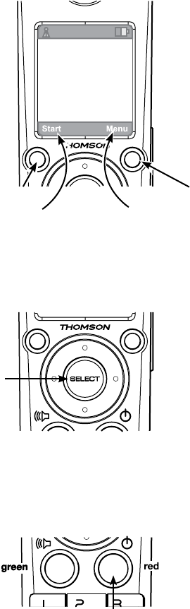
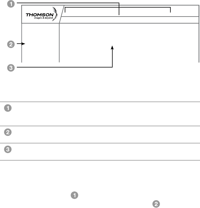
Using the Handset
Softkeys
The Handset has two softkeys that
serve multiple functions.
The text shown above the softkey
indicates the current function of the
key.
If no text is shown, then the key has
no function.
NavKey (Navigation Key)
Use the NavKey to move around
(up, down, left, right) within the
menu screens
and
for positioning the cursor when
editing text.
Press the center of the NavKey to
select an option within the menu
screen (these are typically highlighted
items).
When on a phone call, use the
up or down NavKey to adjust the
volume.
OFF (Red Key)
When on a phone call, press this
key to end a call (hang up).
Return to the Home Screen by
pressing the Red Key when within
any menu or submenu.
Becoming Familiar with Handset Operation
Press this
softkey
to select
this action
Press this softkey
to select
this action
NavKey
SELECT
OFF Key
19
Using the Handset
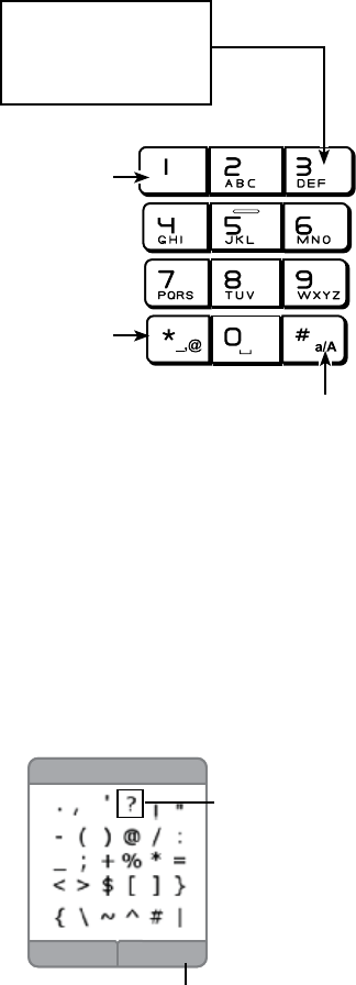
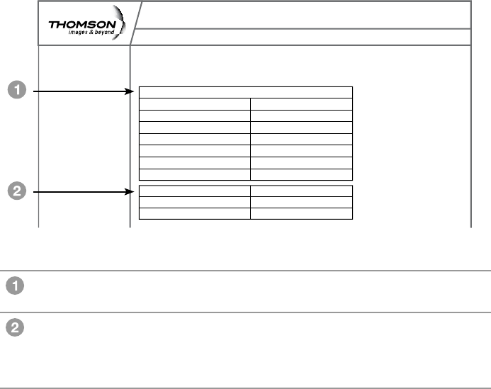
Entering Text
Use the keypad to enter characters
while in a text entry eld.
The rst key press will display the
rst character presented on the key
(refer to sample at left).
Pressing the key repeatedly will
cycle through the characters on the
key.
Text entry tips:
Pressing the # key in text entry
mode alternates among the
following:
lower case•
upper case •
numeric •
The upper right corner of the
screen will display which mode is
activated.
Press 1 to enter a space in lower or
upper case mode.
If in numeric mode, pressing 1 will
enter the number 1.
If a special character is needed,
press the Star key (the lower left
corner key) to view a screen of
these characters.
Use the navkey to highlight the
character that is needed. Push the
Yes softkey to place the character
into your line of text.
Sample of Text Entry:
1st press = D
2nd press = E
3rd press = F
4th press = D
cycle repeats
# Key
changes mode
Upper Case/ Lower Case / Numeric
1 Key
enters a space
in text mode
(Of course, in
numeric mode
it enters 1)
Press for
special
characters
Highlighted
character
Press this softkey to type the
highlighted character.
BackYes
Special Charaters

20
Using the Handset
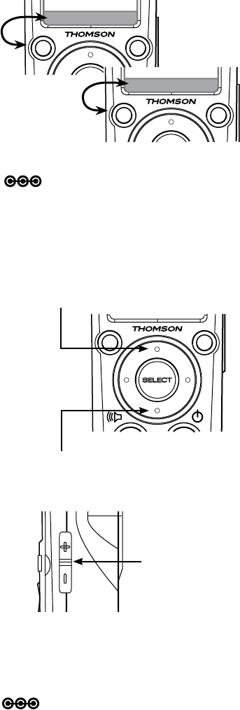
Note: The speakerphone provides you a hands-free option while on a call.
During a call, press the green key to alternate between speakerphone
and normal handset use.
Note: The screen displays the elapsed time of the call (in hours, minutes
and seconds) and the telephone number you dialed while you are on
a call. After a call ends, the call summary will be displayed, showing
the length of the call in hours, minutes and seconds.
Day to Day Use
Making Calls
To make a standard telephone call,
press the green key (talk key) and then
dial the number. If you want to use
the speakerphone, press the green
key a second time and then dial the
number.
For pre-dialing, (preview numbers
before dialing)enterthenumbersrst.
If you make a mistake when dialing
use the NavKey (navigation key) to
place the cursor to the right of the
number you want to delete and press
the softkey remove to delete the
number. After entering the number,
press the green key.
Receiving Calls
When the telephone is ringing, press
the green key to answer the call.
Press a the green key a second
time if you want to answer using the
speakerphone.
Green key
Press once:
regular call
Press twice:
speakerphone
Press Red Key:
OFF
Ending Calls
While you are on a call, press the red
key (OFF key) to end the call.
21
Using the Handset
Mute Flash
Call Volume
You can adjust the listening volume
from the earpiece or speakerphone
during a call.
While on a call, press UP or DOWN
of the NavKey to adjust the volume of
the earpiece.
Mute
During a call, press the Mute softkey
to mute the microphone.
Press the UnMute softkey to resume
normal conversation.
For the Earpiece, press the UP Navkey to
raise volume
Press the DOWN Navkey to lower volume
Press the
Sidekey
UP or DOWN
to adjust the
Speakerphone
volume
Start
M
en
u
Note: The Mute function is used to silence the microphone during a
conversation. You will be able to hear the caller, but the caller will
not be able to hear you until you press the UnMute softkey to
resume the conversation. When you hang up the telephone, the
feature will be canceled.
Note: After adjustment, a volume bar will appear on the screen. It will only
be displayed for three seconds and the volume level will be saved
automatically.
Unmute Flash
To raise or lower the sound level of the
speakerphone, press the UP/DOWN
button on the Sidekey.
22
Using the Handset
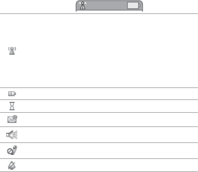
Handset Screen Icons
As you move from screen to screen, the icons at the top of the screen change
and display important information:
Top Bar Icons
Login Menu
The visibility and color of this icon tell you
the status of the phone’s connection
Green : the handset is registered to the Advanced Cable
Gateway and has a connection
Red : the handset is registered to the Advanced Cable
Gateway but does not have a connection at this
time
Not Visible : the handset you are using is not registered
Battery Indicator : displays when the battery is charging.
Busy/Waiting
Email Alert
Handsfree “Loudspeaker”
Mute
The ringer volume is off.

23
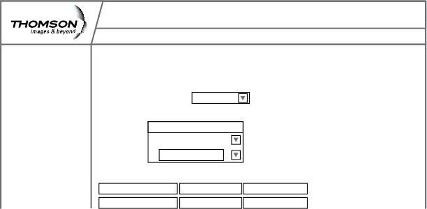
Web Conguration
Access and Change Gateway Advanced Settings
The Gateway offers local management capability through a built in HTTP
serverandanumberofdiagnosticandcongurationwebpages.Youcan
congurethesettingsbywayofthewebpageandapplythemtothedevice.
OnceyourhostPCisproperlycongured;pleaseproceedasfollows:
Start your web browser and 1.
type
http://cable.cong/
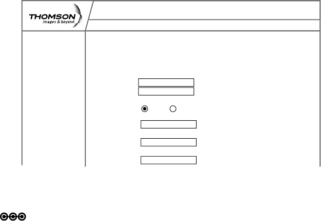
After connecting to the site, 2.
you will be asked to enter
username and password.
By default,
the Login Name is: ______
(leavetheeldblank)
Password is: admin
If you log in successfully, the main
webpage will appear.
You can also access these pages by
inserting the CD that came with your
Gateway.
Connect to 192.168.100.1 ? X
Thomson
User name:
Password:
Remember my password
OK Cancel
24
Web Conguration
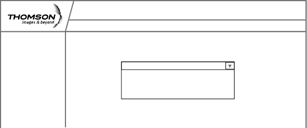
Outline of Web Manager
The main screen will be shown as below.
Select a Main Menu itemrstandthepagesorgroupsofpages
associated with that topic will appear in the sidebar . This
arrangement makes navigation easy.
Main Menu The hyperlinks on the top of the page, including
Gateway, VoIP, Router, Wireless, eMTA-Settings
and several sub-menu items.
Title The sidebar on the left side of the page indicates
the title of this management interface.
Main Window The current workspace of the web management
containingcongurationorstatusinformation.
Administration
Status - Telephony - Router - Wireless eMTA-Settings
Gateway
Software
Connection
Password
Welcome to Thomson Advanced Cable Gateway configuration pages. These pages provide information
on your Gateway and allow you to configure its telephone and networking features.
Thomson Advanced Cable Gateway Configuration
25
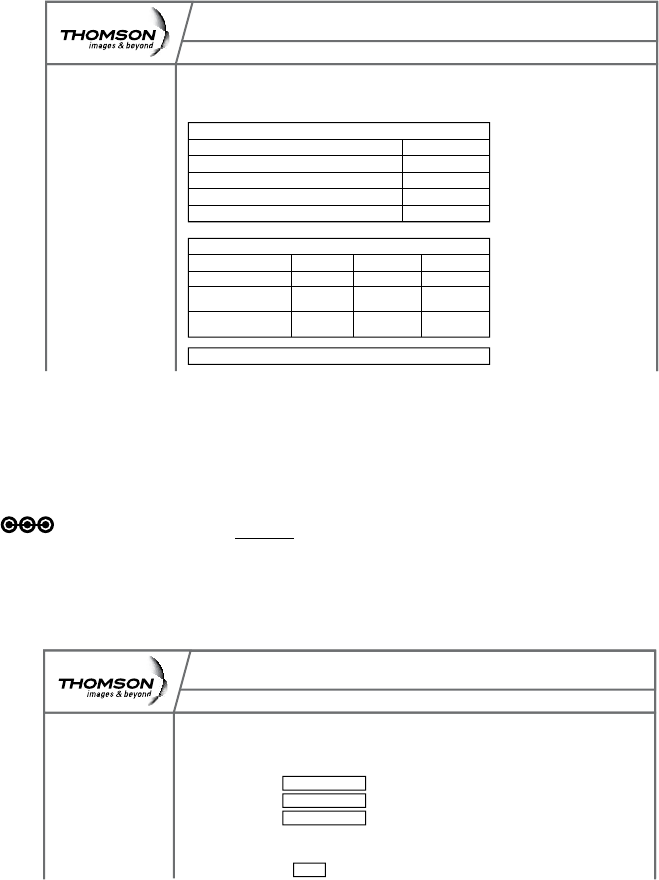
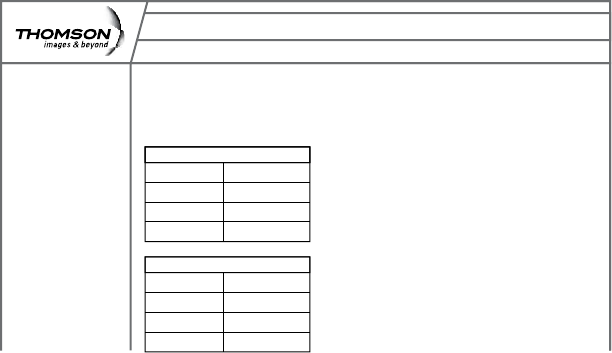
Web Conguration
Gateway – Status Web Page Group
1. Software
Administration
Status - Telephony - Router - Wireless eMTA-Settings
Gateway
Status
Software
Connection
Password
Software : This page displays information on the current system software.
Information
Standard Specification Compliant DOCSIS 2.0
Hardware Version ACG90x rev 0
Software Version cable ACG905 1.4.5.0
DOCSIS Software Version 2.0.0 alpha5
DECT Software Version 1252.64
Cable Modem MAC Address 00:1E:69:A0:01:9D
Cable Modem Serial Number 87003804790030
Status
System Up Time 0 days 0h:02m:10s
Router IP Address
Information Section shows the hardware and software
information about your Gateway.
Status Section shows how long your Gateway has operated
since last time being powered up and some key
information the cable modem received during the
initialization process with your cable company.
26
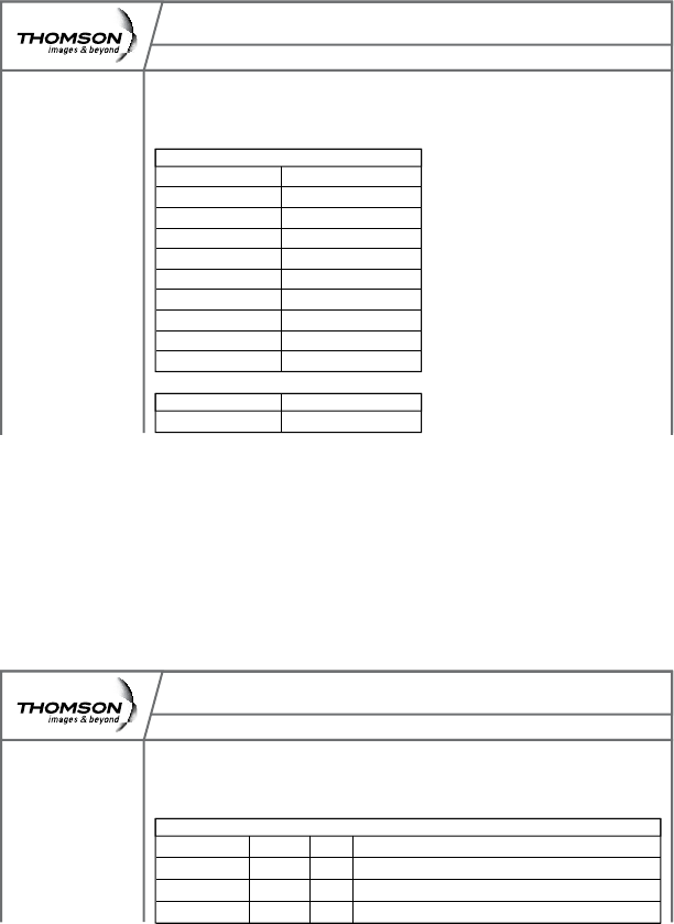
Web Conguration
2. Connection
This page reports Current Connection Status containing startup procedures,
downstream and upstream status and so on. The information can be useful to
your cable company’s support technician if you’re having problems.
3. Password
This page is used to Change the Password that enables you to access the
Gateway web pages next time.
Note: The default User Name is: ________(leavetheeldblank)
The Password is: admin
The user name and password can be a maximum of 15 characters
and are case sensitive.
Administration
Status - Telephony - Router - Wireless eMTA-Settings
Gateway
Status
Software
Connection
Password
Connection: This page displays information on the status of the cable modem’s H
FC and IP connectivity
Startup Procedure
Procedure Status
Acquire Downstream Channel Complete
Connectivity State Complete
Boot State Complete
Configure File Complete
Downstream Channel
Lock Status Not Locked Modulation Unknown
Channel ID 0 Symbol rate Unknown
Downstream 253000000 Downstrean -6,300000
Frequency Hz Power dBmV
SNR 23.200000
dB
Upstream Channel
Administration
Status - Telephony - Router - Wireless eMTA-Settings
Gateway
Status
Software
Connection
Password
Password: This page allows administration of access privileges and the ability
to restore factory defaults to the system.
User Name
Password *****
Re-Enter Password *****
Apply
27
Web Conguration
Gateway – Telephony Web Page Group
1. Base
This page displays information on the DECT Handset base station
2. Handsets
This page displays information on the DECT Handsets subscribed to the ACG
Administration
Status - Telephony- Router - Wireless eMTA-Settings
Gateway
Telephony
Base
Handsets
Password
Base : This page displays information on the DECT base system.
Information
Standard Specification Compliant PacketCable 1.0
Software Version 1249
EEPROM Revision 64
REPI 00FS400930
Administration
Status - Telephony- Router - Wireless eMTA-Settings
Gateway
Telephony
Base
Handsets
Password
Handsets : This page displays information on the DECT handsets.
Subscribed Handsets
Handset 1 subscribed, narrowband
Handset 2 subscribed, narrowband
Handset 3 subscribed, narrowband
Handset 4 subscribed, narrowband
Handset 5 subscribed, narrowband
Clear all SubcriptionsUpdate Status
Subscribe a Handset
28
Web Conguration
Gateway – Router Web Page Group
1. LAN
By default the DHCP server function for the LAN is activated.
LANsettingscanbemodiedonthispage.
With this function activated, your cable company’s DHCP server provides one
IP address for your Gateway.
Your Gateway’s DHCP server provides IP addresses to your PCs within the
rangeofaddressesspeciedintheDHCPrangestartandstopaddresselds.
A DHCP server leases an IP address with an expiration time.
For example, to change the lowest IP address that your Gateway will issue
to your PCs, enter it into the DHCP Range Start Address box and then click
Apply.
Note: It is highly recommended that these setting not be changed.
Administration
Status - Telephony - Router - Wireless eMTA-Settings
Gateway
Router
LAN
WAN
Computer
Firewall
Forward
DMZ
LAN: This page allows configuration and status of the optional internal
DHCP server for the LAN.
Network
Configuration
IP Address: 192.168.0.1
Subnet Mask: 255.255.255.0
DHCP Server Yes No
DHCP Range
Start Address: 192.168.0.10
DHCP Range
Stop Address: 192.168.0.99
DHCP Lease
Time 24h

29
Web Conguration
2. WAN
This page displays information on the WAN parameters of the Gateway.
3. Computers
This page displays the status of the DHCP clients (lists all computers
connected to your computer) - Computer name, IP address and mac address.
In addition the interface of each computer is displayed.
Administration
Status - Telephony - Router - Wireless eMTA-Settings
Gateway
Router
LAN
WAN
Computer
Firewall
Forward
DMZ
WAN : This page displays information on the WAN parameters of the gateway
WAN IP Address: 10.22.15.7
Expires in: 4d:15h:52m:2s
Administration
Status - Telephony - Router - Wireless eMTA-Settings
Gateway
Router
LAN
WAN
Computer
Firewall
Forward
DMZ
Computer : This page shows the status of the DHCP clients
DHCP Clients
Computer Status IP Address MAC Address Interface
30
Web Conguration
4. Firewall
ThispageallowsyoutochoosetherewallsettingsoftheGatewayinorder
to protect the computers within your home network from malicious attacks
from outsiders. In addition you can use this feature to restrict a computer
withinyourhomenetworkfromaccessingcertianInternettrafcbyIP
address and by logical ports.
3 security levels are proposed:
Minimum (default)
Medium
Maximum
Minimum Level of Security
Theminimumlevelallowsalltheincomingandoutgoingtrafc,
except for:
Windows Ports: •
137, 138, 139. These ports are used for local networks.
So, the Firewall allows a minimum level of security. Apple products are also
supported
Medium Level of Security
Thislevelofsecurityblocksalltheincomingtrafcandallowsalloutgoing
trafc.
Already established connections are accepted.
Administration
Status - Telephony - Router - Wireless eMTA-Settings
Gateway
Router
LAN
WAN
Computer
Firewall
Forward
DMZ
Firewall : This page allows you to restrict a computer within your home network
from accessing certain internet traffic by IP address and by logical ports.
Security Minimum
Minimum
Medium (filter input)
Maximum (filter both input and output)
31
Web Conguration
Maximum Level of Security
Thislevelblocksalltheincomingandoutgoingtrafcwiththefollowing
exceptions:
Connections to the following services (servers located on the •
WAN) are accepted:
FTP (port 20/21)•
www.(port 80) in TCP•
http (port 443) in TCP•
SMTP (port 25) in TCP and UDP•
POP2 (port 109) in TCP and UDP •
POP3 (port 110) in TCP and UDP•
nntp (port 119) in TCP•
All the packets of an already established connection are accepted.
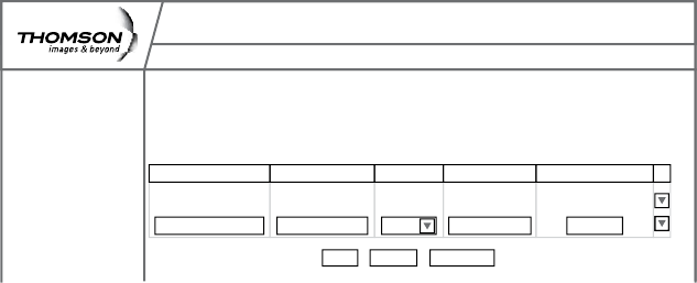
5. Forwarding
For LAN / WAN communications, the Gateway normally allows you to
originate an IP connection only with a PC on the WAN; it will ignore attempts
of the WAN PC to originate a connection onto your PC.
This protects you from malicious attacks from outsiders.
However, sometimes you may wish for anyone outside to be able to
originate a connection to a particular PC on your LAN, if the destination port
(application) matches one that you specify.
Administration
Status - Telephony - Router - Wireless eMTA-Settings
Gateway
Router
LAN
WAN
Computer
Firewall
Forward
DMZ
Forwarding : This allows for incoming requests on specific port numbers to reach
web servers, FTP servers, mail servers, etc. so they can be accessible from the
public internet. A table of commonly used port numbers is also provided
Application Name Source Port(s) Protocol IP Address Destination Port
HTTP 80 TCP 192.168.0.5 80
0 Both 0000 0
Remove AllCancel
Apply

32
Web Conguration
This page allows you to specify up to 9 such rules. The IP address can be
entered multiple times with different ports. For example, to specify that
outsiders should have access to an HTTP server (HTTP on port =80) (HTTP
port) amd Protocol = TCP (HTTP runs over TCP)
Create 1 rule with that address and with Source Port = 80 and •
Destination Port =80 (HTTP port) and Protocol = TCP (HTTP runs over
TCP)
click on “+” to enter this rule•
Click“apply”tovalidatetheconguration•
This will cause inbound packets that match to be forwarded to that •
PC rather than blocked
Buttons + and – are used to add and remove a rule
Button apply is used to validate the rules entered
Button cancel is used to cancel the last action
Button remove all is used to remove all the rules
List of common applications and ports they use:
AUTH : port 113•
DNS : port 53•
FTP : port 21•
FTP_DATA : port 20•
FTP_SRV : ports 1024 to 65535•
HTTP : port 80•
HTTPS : port 443•
IPSEC : port 500•
NTP : port 123•
Note: For certain data transfer applications (FTP for example), you have to
use rewall security levels minimum or medium because most of the
trafc is blocked in the maximum level of security.
POP3 : port 110•
PPTP : port 1723•
SMTP : port 25•
SSH : port 22•
TELNET : port 23•
TFTP : port 69•
VNC : port 5900•
VNC_http : port 5800•

33
Web Conguration
6. DMZ Host
Use this page to designate one PC on your LAN to be exposed to the Internet
for use of a special-purpose service (for example - internet games or video
conferences). DMZ hosting opens all ports of a PC.
Warning: in the DMZ, the computer becomes exposed and visible directly
from the Internet so becomes more vulnerable to hackers. (see the Router/
forwardingsectiononpage29toopenonlyspecicportsonyourPC)
Administration
Status - Telephony - Router - Wireless eMTA-Settings
Gateway
Router
LAN
WAN
Computer
Firewall
Forward
DMZ
DMZ Host (Exposed Host) : This page allows you to open all ports on one chosen
computer. Warning, in the DMZ, the computer becomes exposed or visible directly
from the Internet and, because of this, becomes more vulnerable to hackers.
DMZ Address:
Remove Cancel
Apply

34
Web Conguration
Gateway – Wireless Web Page Group
Important - Changes to the Wireless Web Pages should be made from a PC
that is hard wired to the Gateway.
The Wireless Web Pages Group enables a variety of settings that can provide
secure and reliable wireless communications.
The Advanced Cable Gateway offers a choice of the following:
WEP and WPA/WPA2 authentication of your PCs to the Gateway•
Encryption keys for communication between the Gateway and your •
PCs to guarantee security
An Access Control List function that enables you to restrict wireless •
accesstoonlyyourspecicPCs.
Performance
Because your wireless communication travels through the air, the default
wireless channel setting may not provide optimum performance in your
home if you or your neighbors have other interfering 2.4GHz devices such as
cordless phones.
If your wireless PC is experiencing very sluggish or dramatically slower
communication compared with the speed you achieve on your PC that is
wired to the Gateway, try changing the channel number.
See the 802.11b/g Basic Web Page discussion below for details.
Authentication
Authentication enables you to restrict your Gateway from communicating
with any remote wireless PCs that aren’t yours. The following minimum
authentication-related changes to factory defaults are recommended.
See the 802.11b/g Basic and Access Control Web Page discussions below
for details.
Network Name (SSID) – Set a unique name you choose
Access Control List – Enter your wireless PCs’ MAC addresses
35
Web Conguration
Security
Security secures or scrambles messages traveling through the air between
your wireless PCs and the gateway, so they can’t be observed by others.
The following minimum security setting changes to factory defaults are
recommended.
Change the default Network name of SSID•
EnablemacaddresslteringbyusingtheAccesscontrollistfeatures•
Choose WPA/WPA2 encryption•
See the 802.11b/g Security Web Page discussion below for details.
1. 802.11b/g Basic
Tosetthebasiccongurationforthewirelessfeatures,clickBasic from the
Wireless menu.
Note: These must match the settings you make on your wireless-equipped
PC on the LAN side.
The SSID is your Network Name.
Change the default to a name of your choice up to 32 characters •
long.
The wireless radio in your Gateway can be completely de-activated •
by changing Interface to Disabled).
Click the • Apply button to save your settings.
The Gateway WiFi radio frequently transmits a beacon signal which can
contain this network name (SSID).
The network Type is Open, so your SSID is included in that beacon, and is
therefore detectable by any nearby wireless equipped PCs in the area.
Administration
Status - Telephony - Router - Wireless eMTA-Settings
Gateway
Wireless
Basic
Security
Access Control
802.11b/g Basic : This page allows configuration of the Access Point parameters,
including the SSID and channel number.
Interface Enabled
Wireless MAC Address: 00:19:df:80:00:68
Network Name (SSID) ACG Welcome
New Channel 5
Current Channel 5
Data Encryption Mode: wpa2
CancelApply

36
Web Conguration
Setting Description Value List or
Range Default
Interface
Enable or disable
the wireless
interface.
Enabled,
Disabled Enabled
Wireless Mac
Address
The Mac address
of the wireless
card installed is
displayed
Network Name
(SSID)
Set the Network
Name (also
known as SSID)
of this network.
Up to
32-character
string containing
ASCII characters
with codes
between 0x20
and 0x7e
THOMSON-
ACG-XXXX as
preconguredby
the factory
New Channel
Select a
particular
channel on which
to operate.
1-13 11
Data Encryption
Mode
The data
encryption mode
currentlyusedis
displayed
WPA-PSK
(TKIP)

37
Web Conguration
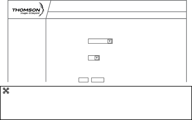
2. 802.11b/g Security
ThispageallowsyoutoconguretheNetworkAuthentication.
This page provides several different modes of wireless security.
You will have to enter proper information according to the mode you select.
A network encrypted with WPA/WPA2 is more secure than a network
encrypted with WEP, because WPA/WPA2 uses dynamic key encryption. To
protect the information as it traveling through the air, you should enable the
highest level of encryption supported by the ACG: WPA2-PSK (AES)
WPA2-PSK (AES)
To enable WPA2
(Make sure that your wireless client and client manager are compatible with
it.)
Choose WPA2-PSK (AES) in the security drop down menu.
Select a passphrase: the passphrase is composed of more than 8
alphanumerical characters. Upper and lower case characters can be used.
Use a strong passphrase which combines letters and numbers.
(The alphanumeric character set consists of the numbers 0 to 9 and letters A
to Z.)
Administration
Status - Telephony - Router - Wireless eMTA-Settings
Gateway
Wireless
Basic
Security
Access Control
802.11b/g Security : This page allows configuration of the security, WEP key or
WPA passphrase.
Security WPA2-PSK(AES)
WPA Passphrase
Cancel
Apply
Click on apply
WPA2-PSK (AES) authentication and encryption
The authentication uses a 4-way handshake to check wether the Pre shared
Keys (PSKs) are identical.
Advanced Encryption Standard () is the state of the art encryption mechanism
which provides the highest form of security for home users.
38
Web Conguration
Other security modes available:
WPA-PSK (TKIP)
This is the default security mode.
Temporal Key Integrity Protocol (TKIP) is used for dynamic encryption of the
data.
WEP-Open and WEP-Shared
If one of these security modes is chosen, you have to enter a 128 bits
encryption key
Encryption Key 128 bits
The key used for WEP is a 128 bit hexadecimal ([0-9] [A-F]) key.
The key is composed of 26 hexadecimal characters.
39
Web Conguration
3. Access Control
This page allows you to ensure security by setting an access control to the
Access Point (AP). Access control is done on client’s mac addresses
MAC Restrict Mode: Click Disabled to welcome all of the clients on the
network (default setting).
Click Allow to permit only the clients on the list to access the cable modem.
Click Deny to prevent the clients on the list to access this device.
MAC Address: YourGatewayidentieswirelessPCsbytheirWiFi
MAC Address.
This address consists of a string of 6 pairs of numbers
0-9 and letters A-F, such as 00 90 4B F0 FF 50.
It is usually printed on the WiFi card of the device (e.g.
the PCMCIA card in a laptop).
Enter the MAC addresses of the connected clients
intotheelds,andthenclickApplytoaddthemto
the list for access control. A maximum of 9 MAC
addresses can be entered.
+ : Afterproperconguration,clickonthe+buttonto
invoke the settings.
Connected Clients: The information of currently connected clients will be
displayed here.
Administration
Status - Telephony - Router - Wireless eMTA-Settings
Gateway
Wireless
Basic
Security
Access Control
802.11b/g Access Control : This page allows configuration of Access Control
to the AP as well as status on the connected clients.
MAC Restrict Mode Allow
Connected Clients
Computer Home IP Address MAC Address
MAC Addresses
00:14:BF:9F:AB:B4
40
Web Conguration
eMTA settings – Basic Web Page Group
This group of pages gives information on the hardware and the state of your
cable connection. The access to this groupof pages is protected by a static
password: no username, password:Thomson
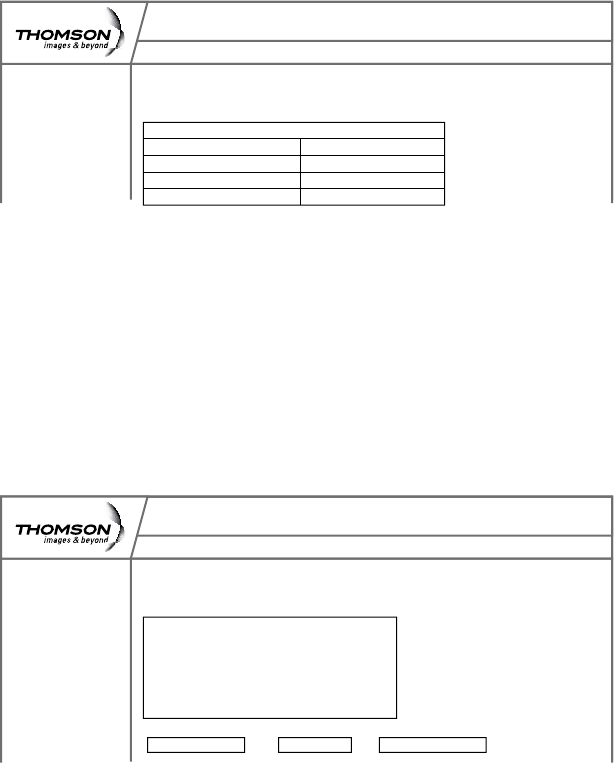
1. Status
This page displays:
Basic LAN Status of This Device •
(including the downstream and upstream status)
Device Information•
Interface Parameters •
Administration
Status - Telephony - Router - Wireless eMTA-Settings
Gateway
Basic
Status
Status
CM Hardware
Event Log
CM State
This page displays information on the status of the cable modem’s HFC and
IP connectivity.
RF Downstream
Frequency: 405.000 MHz
Power: 13.5 dBmV
SNR: 39.5 dB
Modulation: QAM-256
RF Upstream
Frequency: 33.000 MHz
Power: 43.8 dBmV
SNR: 2560Ksym/sec
Modulation: QPSK
41
Web Conguration
2. CM Hardware
The CM hardware is displayed on this page.
3. Event Log
The CM event log is displayed on this web page.
Administration
Status - Telephony - Router - Wireless eMTA-Settings
Gateway
Basic
Hardware
Status
CM Hardware
Event Log
CM State
This page displays the CM and MTa event logs.
CM Hardware
HW Revision: 0
Vendor: Thomson
BOOT Revision: 2.1.8o
SW Revision: 2.0.0alpha3
Model: ACG905
Product Type: ACG905
Flash Part:
Download Revision: (unknown)
Software Revision: 2.0.0alpha3
Serial number: 87003804790087
MTA Hardware
MTA Serial Number: 87003804790087
Administration
Status - Telephony - Router - Wireless eMTA-Settings
Gateway
Basic
Event Logs
Status
CM Hardware
Event Log
CM State
This page displays the CM and MTa event logs.
CM Event Log
Date/Tme Event Level Event ID Description
03/03/2008 19:23 Critical (3) D3.0 DHCP WARNING - Non-critical field invalid in response
01/01/2000 00:02 Critical (3) R2.0 No Ranging Respnonse received - T3 time-out
01/01/2000 00:02 Critical (3) T1.0 SYN Timing Synchronization failure - Failed to acquire QAM/QPSK

42
Appendix - Customizing Your Handset
4. CM State
This page shows the current state of the cable modem.
Administration
Status - Telephony - Router - Wireless eMTA-Settings
Gateway
Basic
CM State
Status
CM Hardware
Event Log
CM State
This page displays the state of the CM/MTA.
CM Hardware
CM State: Operational
Docsis-Downstream Scanning Done
Docsis-Ranging Done
Docsis-DHCP Done
Docsis-TFTP Done
Docsis-Data Reg Complete Done
Telephony-DHCP Completed
Telephony-Security Disabled
Telephony-TFTP Completed
Telephony-Reg with Call Server L1: Operational/L2: Operational

43
Appendix - Customizing Your Handset
Handset ID
Register Handset
Select Base
De-Register
Registration
Ring Tone
Ring Tone
Ring Volume
Beep Tone
External Calls (choice of 5 ringtones)
Internal Calls (choice of 6 ringtones)
Key Beep (on/off)
Low Battery (on/off)
Out of Range (on/off)
Notifications (on/off)
Alarm
Time Format
on/off
Set Alarm Tone
Time
Settings
System PIN
Ear Volume
Contrast
Backlight
Auto Talk
Handset Update
Handset Settings
Base Settings
Reset to Default
Phone
Settings
Additional Information
Customize Your Handset
Chart of the Menus
While in the home screen press the menu softkey. Select the settings icon to
access the settings menu of the phone.
The menu structure is as follows:
CONFIRM - When working in the screens on your handset, there are two
ways to conrm your selections. In most screens you will use a softkey for
“OK”; but, if that is not available, use the “Select” key located in the center of
the navigation key.
44
Appendix - Customizing Your Handset
1. Ring Tone
a. Selecting a Ring Tone
Inthehomescreen,select“Menu”bypressingthesoftkey.•
Selectthesettingsiconandconrm.•
Select“RingTone”andconrm.•
Select“Ringtone”andconrm.•
Select“ExternalCalls”or“InternalCalls”andconrm.•
Selecttheringtoneyouwantandconrmbypressingthesoftkeyfor•
“Use”.
b. Adjusting the Ringer Volume
Inthehomescreen,select“Menu”bypressingthesoftkey.•
Selectthesettingsiconandconrm.•
Select“RingTone”andconrm.•
Select“RingVolume”andconrm.•
Usetheupanddownkeytoadjustthevolumethenconrm.•
c. Changing the Beep Tones Settings
To turn beep tones on (or off):
Key Beep:
In the home screen, select “Menu” by pressing the softkey. •
Selectthesettingsiconandconrm.•
Select“RingTone”andconrm.•
Select“BeepTones”andconrm.•
Select“KeyBeep”andconrm.•
Select“Off”or“On”andconrm.•
Low Battery:
In the home screen, select “Menu” by pressing the softkey.•
Selectthesettingsiconandconrm.•
Select“RingTone”andconrm.•
Select“BeepTones”andconrm.•
Select“LowBattery”andconrm.•
Select“Off”or“On”andconrm.•
45
Appendix - Customizing Your Handset
Out of Range:
In the home screen, select “Menu” by pressing the softkey.•
Selectthesettingsiconandconrm.•
Select“RingTone”andconrm.•
Select“BeepTones”andconrm.•
Select“OutOfRange”andconrm.•
Select“Off”or“On”andconrm.•
Notications:
In the home screen, select “Menu” by pressing the softkey. •
Selectthesettingsiconandconrm.•
Select“RingTone”andconrm.•
Select“BeepTones”andconrm.•
Select“Notify”andconrm”.•
Select“Off”or“On”andconrm.•
2. Time
a. Customizing the Alarm Ringer
Inthehomescreen,select“Menu”bypressingthesoftkey.•
Selectthesettingsiconandconrm.•
Select“TimeSettings”andconrm.•
Select“Alarm”andconrm.•
Select“AlarmTone”andconrm.•
Selecttheringertype(radioorringtone)andconrm.•
Note: If you select a radio channel that proves to be unavailable, a
ringtone will be played instead.
46
Appendix - Customizing Your Handset
3. Phone Settings
a. Changing the Display Contrast
Inthehomescreen,select“Menu”bypressingthesoftkey.•
Selectthesettingsiconandconrm.•
Select“Handset”andconrm.•
Select“Contrast”andconrm.•
Usetheupanddownkeystoadjustthecontrastandconrm.•
b. Auto Talk
Auto Talk “ON”- If you pick up the handset from the dock when the
phone is ringing, the handset will automatically give you that ringing
line without the need to press the green (talk) button.
Auto Talk “OFF” - In the same situation, you will have to press the talk
button to answer the ringing phonecall.
Inthehomescreen,select“Menu”bypressingthesoftkey.•
Selectthesettingsiconandconrm.•
Select“Handset”andconrm.•
Select“AutoTalk”andconrm.•
Select“Off”(or“On”)andconrm.•
c. Restoring the Default Settings
This option allows you to restore the Handset to its original default
settings. This procedure will reset the base PIN (0000 by default).
However, all the numbers stored in the phonebook, the call log and the
most recently-dialed numbers list will be retained.
Inthehomescreen,select“Menu”bypressingthesoftkey.•
Selectthesettingsiconandconrm.•
Select“DefaultSettings”andconrm.•
Enter the PIN • (0000 by default)andconrm.
47
Appendix - Customizing Your Handset
4. Call Lists
a. Understanding Caller Identication Data
If you subscribe to your network provider’s “Caller Identication”
(caller ID) service, you can see who is calling you before you take the
call.
If you subscribe to the “Call Waiting” service as well, the same
identicationprocessappliestocallsreceivedwhenyouarealready
on a call.
The calls made and received are logged automatically, together with
number, date and time.
The following messages may be displayed on-screen during the call:
Caller’snameandnumber-• if the caller’s number is forwarded by the
network,
“Withheld”ifthecallerisusingthesecrecyfunction,or“Unavailable”if•
thenetworkdoesnotforwardthenameornumber,
“ExternalCall”willdisplayifyoudonotsubscribetothe“Caller•
Identication”service.
b. Viewing the Call List
Ifyousubscribetoyournetworkprovider’s“CallerIdentication”
service, your system will store details of calls made and received,
together with their date and time.
48
Appendix - Customizing Your Handset
5. Using Your Phone With Multiple Handsets
a. Registering/Re-Registering an Extra Handset
You can have up to 5 handsets registered to your Advanced Cable
Gateway system base. Refer to Thomson URL to see how addtional
Handsets may be purchased.
If you already have 5 handsets registered and you want to swap one
of them, you must remove that handset from your list of registered
phones (uninstall it) before installing the replacement handset.
On the base:
Switch the base to registration mode.•
On the handset:
Select“Menu”bypressingthesoftkey.•
Selectthesettingsiconandconrm• .
Select“Registration”andconrm.•
Select“RegisterHandset”andconrm.•
Select the base to be associated with this handset • (1 to 4)andconrm.
Enter the system PIN • (0000 by default)andconrm.
Wait3to4minutesfortheconrmationscreen.•
YourHandsetisnowregistered.•
b. Selecting a Base
Each Handset may be registered to 4 different Gateway bases.
If you register your handset with a non-Thomson Advanced Cable
Gateway base, you will not be able to access the data functions.
To change base:
Select“Menu”bypressingthesoftkey.•
Selectthesettingsiconandconrm• .
Select“Registration”andconrm.•
Select“SelectBase”andconrm.•
Selectthenumberofthebaseusingtheupanddown• (navigation) keys
(1 to 4) andconrm.
Thebasestowhichthehandsetisregisteredareidentiedbythe[]•
symbol.
49
Appendix - Customizing Your Handset
c. Un-Registering a Handset
Handsets can only be un-registered from another Handset.
Select“Menu”bypressingthesoftkey.•
Selectthesettingsiconandconrm• .
Select“Registration”andconrm.•
Select“De-Register”andconrm.•
Enter the secret system PIN • (0000 by default)andconrm.
Usingtheupanddown(navigation)keys,selecttheHandsettobeun-•
registeredandconrm.
d. Making/Taking an Intercom Calls
Making an intercom call
Onthekeypad,selectthenumberoftheinternalHandsetyouwantto•
call (1 to 5) then press the (green) talk key.
Taking an intercom call
When you receive an internal call, the screen displays the number of
the calling Handset and “Internal Call”.
Press • (green) talk key or the answer softkey to answer the call.
To hang up at the end of the call, press the (red) OFF key.
50
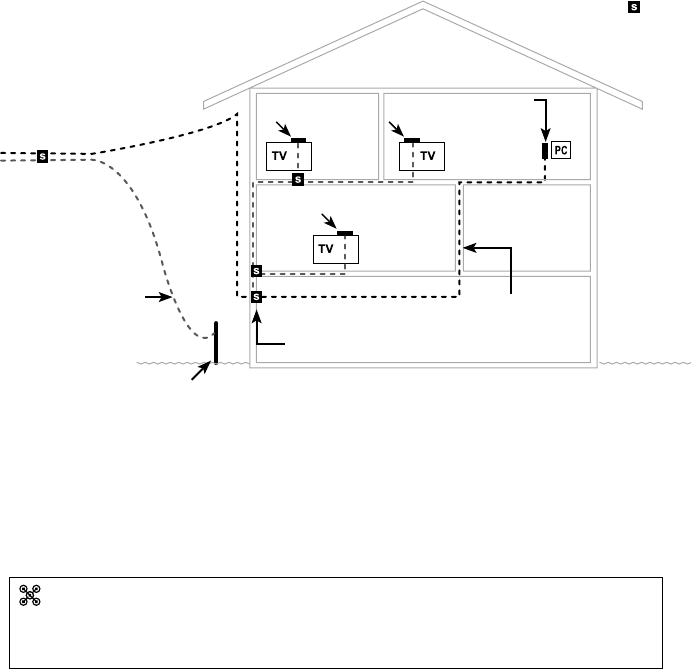
Appendix - Wiring
Wiring Example
For optimum performance, be sure to connect your Advanced Cable
Gateway to the rst point the cable enters your home.
The splitter must be rated for at least 1GHz.
Grounding Wire
Grounding Rod
New Cable Wire
ACG
Modem
TV
converter
TV
converter
TV
converter
Splitters -
New 2-way splitter:
One leg goes directly to the ACG (modem)
One leg goes directly to the IN on the next splitter
Cable Drop
51
Appendix - FAQ
Frequently Asked Questions
Q. How does the Advanced Cable Gateway Work?
A. The Advanced Cable Gateway provides high-speed Internet access
as well as cost-effective, telephone voice and fax/modem services for
residential subscribers over a CATV (cable TV) infrastructure. It can
inter-operate with the PacketCable compliant head end equipment and
provideIP-basedvoicecommunications.TheIPtrafccantransfer
between the Advanced Cable Gateway and DOCSIS compliant head
end equipment. The data security secures upstream and downstream
communications.
Q. How do I get the system installed?
A. Your cable service provider can do the installation for you or provide you
with a self-installation kit.
Q. Can I watch TV, surf the Internet, and talk to my friends through the
Advanced Cable Gateway at the same time?
A. Absolutely!
Q. What if my Gateway has a problem?
A. Consult the troubleshooting appendix or contact your service provider.
Q. Where can I get additional handsets?
A. Refer to URL
Q. What do the LED lights mean?
A. Refer to the “Lights Guide” section in Troublshooting.

52
Appendix - Lights Guide
LED LABEL Power
Battery
( LED desc.
when battery
is inserted )
DS/US ONLINE LINK TEL
Boot Up
Operation
PowerOnduring0.25s OFF ON ON ON ON ON
From Power On to System
Synchronization complete ON OFF SLOW
BLINK
SLOW
BLINK OFF OFF
Before DS scanning:
during~15s ON OFF ON ON X
(Note 3) OFF
DOCSIS Start-Up Operation
Note 1
DSscanning&acquiring
SYNC ON ON FAST
BLINK OFF X OFF
From SYNC completed,
receivingUCDtoranging
completed
ON ON SLOW
BLINK OFF X OFF
DHCP ON ON ON FAST
BLINK X OFF
congledownload ON ON ON SLOW
BLINK X OFF
Registration & BPI
initialization ON ON FAST
BLINK
FAST
BLINK X OFF
Operational (NACO On) ON ON ON ON X OFF
Operational (NACO Off) ON ON ON OFF X OFF
Telephone
Provisioning ON ON ON ON XFAST
BLINK
Registered ON ON ON ON X ON
LAN Active
No Ethernet or WiFi Link ON ON ON ON OFF X
Ethernet or WiFi Link ON ON ON ON ON X
Tx/Rx Ethernet or WiFi
Trafc ON ON ON ON FLASH X
ACG in dect association
mode=Pagebuttonhas
been pressed for more
than 12s
ON ON ON ON FAST
BLINK X
* “X” indicates that this LED is not used to show the state of operation described on this line.
Check in this column for the state in which this LED is ON.
Note 1- “Flash” indicates a CM or eMTA initialization process in progress.
A “Flash” that does not stop indicates an initialization error.
Note 2- During an AC Power Failure with a bad battery, the operation of the device
may not be possible due to lack of battery power; all LEDs may be “Unlit”.
Note 3- LED turns on when connection to a PC is detected.
Legend:
ON LED is on SLOW BLINK LED is blinking slowly
OFF LED is off FAST BLINK LED is blinking quickly
XLED can be in any state (on, off or blinking)
Lights Guide Note - There is a simplied version of this table on page (yada yada)

53
Appendix - Lights Guide
LED LABEL Power
Battery
( LED desc.
when battery
is inserted )
DS/US ONLINE LINK TEL
eMTA Normal Operation
AC Power Good
Good Battery
all lines
On-
Hook ON
ON
CM Normal Operation
CM Normal Operation
CM Normal Operation
ON
1 line
or more
Off-Hook ON SLOW
BLINK
Low Battery
all lines
On-
Hook ON
SLOW
BLINK
ON
1 line
or more
Off-Hook ON SLOW
BLINK
Bad Battery
all lines
On-
Hook ON
OFF
NOTE 2
ON
1 line
or more
Off-Hook ON SLOW
BLINK
AC Power Failure
Good Battery
all lines
On-
Hook FLASH
OFF
OFF OFF
OFF
ON
1 line
or more
Off-Hook FLASH SLOW
BLINK
Low Battery
all lines
On-
Hook FLASH
SLOW
BLINK
ON
1 line
or more
Off-Hook FLASH SLOW
BLINK
Bad Battery
all lines
On-
Hook OFF
OFF
NOTE 2 NOTE 2 NOTE 2 NOTE
2
1 line
or more
Off-Hook OFF
SW Download
Operation
During Software
download & while
updating the FLASH
memory
ON ON SLOW
BLINK
SLOW
BLINK
SLOW
BLINK X
Restore
to Factory
Settings
ACG is powered off.
Press the Page button
while powering on the
ACG. Hold the page
button for 5s
Turn on all LEDs when factory RESET starts
eMTA Reset
(soft Reset)
Upon pressing the Rest
button LEDs behave as if the device is powering up
54
Appendix - Troubleshooting
Troubleshooting
You can correct most problems you have with your Gateway by consulting
the troubleshooting list that follows:
I can’t access the internet.
Check all of the connections to your Advanced Cable Gateway.
Your PC is connected to the USB port or your Ethernet card may
not be working. Check if each product’s documentation for more
information.
The Network Properties of your operating system may not be installed
correctly or the settings may be incorrect. Check with your ISP or
cable company.
All of the lights are ashing in sequence.
This means the Advanced Cable Gateway is automatically updating
its system software. Please wait for the lights to stop ashing. The
updating process typically lasts less than one minute.
Do not remove the power supply or reset the Advanced Cable
Gateway during this process.
I can’t get the modem to establish an Ethernet connection.
Even new computers don’t always have Ethernet capabilities – be
sure to verify that your computer has a properly installed Ethernet
card and the driver software to support it.
Check to see that you are using the right type of Ethernet cable.
The modem won’t register a cable connection.
If the modem is in Initialization Mode, the INTERNET light will be
ashing. Call your Cable Company if it has not completed this 5-step
process within 30 minutes, and note which step it is getting stuck on.
The modem should work with a standard RG-6 coaxial cable, but
if you are using a cable other than the one your Cable Company
recommends, or if the terminal connections are loose, it may not
work. Check with your Cable Company to determine whether you’re
using the correct cable.
55
Appendix - Troubleshooting
If you subscribe to video service over cable, the cable signal may not
be reaching the modem. Conrm that good quality cable television
pictures are available to the coaxial connector you are using by
connecting a television to it. If your cable outlet is “dead”, call your
Cable Company.
Verify that the Cable Modem service is DOCSIS compliant and
PacketCable compliant by calling your cable provider.
I don’t hear a dial tone when I use a telephone.
Telephone service is not activated. If the TEL light on the Advanced
Cable Gateway stays on while others ash, check with your TSP or
cable company.
If the TEL light is blinking when the phone is not in use, contact your
service provider.
If the Advanced Cable Gateway is connected to existing house
telephone wiring, make sure that another telephone service is not
connected. The other service can normally be disconnected at the
Network Interface Device located on the outside of the house.
56
Appendix - FCC Information
FCC Declaration of Conformity and Industry Canada Information
This device complies with Part 15 of the FCC Rules. Operation is subject
to the following two conditions: (1) this device may not cause harmful
interference, and (2) this device must accept any interference received,
including interference that may cause undesired operation.
This equipment has been tested and found to comply with the limits for a
Trade Name: Model: ACG905
EquipmentClassication: Computing Device Accessory
Responsible Party: Thomson Inc.
101 W. 103rd St.
Indianapolis, IN 46290 U.S.A.
Class B digital device, pursuant to Part 15 of the FCC Rules. These limits
are designed to provide reasonable protection against harmful interference
in a residential installation. This equipment generates, uses, and can radiate
radio frequency energy and, if not installed and used in accordance with
the instructions, may cause harmful interference to radio communications.
However there is no guarantee that interference will not occur in a particular
installation. If this equipment does cause harmful interference to radio or
television reception, which can be determined by turning the equipment off
and on, the user is encouraged to try and correct the interference by one or
more of the following measures:
Reorient or relocate the receiving antenna.•
Increase the separation between the equipment and receiver.•
Connect this equipment into an outlet on a circuit different from that •
to which the receiver is connected.
Consult the dealer or an experienced radio/TV technician for help.•
FCCregulationsstatethatunauthorizedchangesormodicationstothis
equipment may void the user’s authority to operate it.
This Class B digital apparatus meets all requirements of the Canadian
Interference Causing Equipment Regulations.
57
Appendix - Fcc Information
FCC Declaration of Conformity for Handset
Interference Information
This device complies with Part 15 of the FCC Rules. Operation is subject to the
following two conditions: (1) This device may not cause harmful interference; and (2)
This device must accept any interference received, including interference that may
cause undesired operation.
This equipment has been tested and found to comply with the limits for a Class B
digital device, pursuant to Part 15 of the FCC Rules. These limits are designed to
provide reasonable protection against harmful interference in a residential installation.
This equipment generates, uses, and can radiate radio frequency energy and, if not
installed and used in accordance with the instructions, may cause harmful interference
to radio communications. However, there is no guarantee that interference will not
occur in a particular installation.
Privacy of Communications may not be ensured when using this product.
If this equipment does cause harmful interference to radio or television reception,
which can be determined by turning the equipment off and on, the user is encouraged
to try to correct the interference by one or more of the following measures:
• Reorientorrelocatethereceivingantenna(thatis,theantennaforradioor
television that is “receiving” the interference).
• Reorientorrelocateandincreasetheseparationbetweenthe
telecommunications equipment and receiving antenna.
• Connectthetelecommunicationsequipmentintoanoutletonacircuitdifferent
from that to which the receiving antenna is connected.
If these measures do not eliminate the interference, please consult your dealer or an
experienced radio/television technician for additional suggestions. Also, the Federal
Communications Commission has prepared a helpful booklet, “How To Identify and
Resolve Radio/TV Interference Problems.” This booklet is available from the U.S.
GovernmentPrintingOfce,Washington,D.C.20402.Pleasespecifystocknumber
004-000-00345-4 when ordering copies.
NOTICE:Thechangesormodicationsnotexpresslyapprovedbytheparty
responsible for compliance could void the user’s authority to operate the equipment.
Hearing Aid Compatibility (HAC)
This telephone system meets FCC standards for Hearing Aid Compatibility.
Licensing
Licensed under US Patent 6,427,009.
FCC RF Radiation Exposure Statement
This equipment complies with FCC RF radiation exposure limits set forth for an
uncontrolled environment. This equipment should be installed and operated with
a minimum distance of 20 centimeters between the radiator and your body. This
transmitter must not be co-located or operated in conjunction with any other antenna
or transmitter.”
58
Appendix - Service
Service Information
If you purchased or leased your Advanced Cable Gateway directly from your
cable company, then warranty service may be provided through your cable
provider or its authorized representative. For information on 1) Ordering
Service, 2) Obtaining Customer Support, or 3) Additional Service Information,
please contact your cable company. If you purchased your Advanced Cable
Gateway from a retailer, see the enclosed warranty card.
59
Appendix - Gossary
Glossary
10BaseT Unshielded, twisted pair cable with an RJ-45 connector, used
with Ethernet LAN (Local Area Network). “10” indicates speed
(10 Mbps), “Base” refers to baseband technology, and “T” means
twisted pair cable.
Authentication The process of verifying the identity of an entity on a network.
DHCP - (Dynamic Host Control Protocol)
A protocol which allows a server to dynamically assign IP
addresses to workstations on the y.
Ethernet card A plug-in circuit board installed in an expansion slot of a personal
computer. The Ethernet card (sometimes called a Network
Interface Card or NIC) takes parallel data from the computer,
converts it to serial data, puts it into a packet format, and sends it
over the 10BaseT or 100BaseT LAN cable.
DOCSIS - (Data Over Cable Service Interface Specications)
A project with the objective of developing a set of necessary
specications and operations support interface specications for
Cable Modems and associated equipment.
F Connector A type of coaxial connector, labeled CABLE IN on the rear of the
Advanced Cable Gateway that connects the modem to the cable
system.
HTTP - (HyperText Transfer Protocol)
Invisible to the user, HTTP is used by servers and clients to
communicate and display information on a client browser.
Hub A device used to connect multiple computers to the Advanced
Cable Gateway.
IP Address A unique, 32-bit address assigned to every device in a network. An
IP (Internet Protocol) address has two parts: a network address and
a host address. This modem receives a new IP address from your
cable operator via DHCP each time it goes through Initialization
Mode.
Key exchange The swapping of mathematical values between entities on a
network in order to allow encrypted communication between them.
MAC Address The permanent “identity” for a device programmed into the
Media Access Control layer in the network architecture during the
modem’s manufacture.
Network Driver A le that is loaded on the computer to allow the computer to
recognize the Ethernet card or USB port.
NID - (Network Interface Device)
60
Appendix - Glossary
The interconnection between the internal house telephone wiring
and a conventional telephone service provider’s equipment. These
wiring connections are normally housed in a small plastic box
located on an outer wall of the house. It is the legal demarcation
between the subscriber’s property and the service provider’s
property.
PacketCable A project with the objective of developing a set of necessary
telephony specications and operations support interface
specications for Advanced Cable Gateways and associated
equipment used over the DOCSIS based cable network.
PSTN - (Public Switched Telephone Network)
The worldwide voice telephone network which provides dial tone,
ringing, full-duplex voice band audio and optional services using
standard telephones.
Provisioning The process of enabling the Media Terminal Adapter (MTA) to
register and provide services over the network.
TCP/IP - (Transmission Control Protocol/Internet Protocol)
A networking protocol that provides communication across
interconnected networks, between computers with diverse
hardware architectures and various operating systems.
TFTP - (Trivial File Transfer Protocol)
The system by which the Media Terminal Adapter’s conguration
data le is downloaded.
TSP - (Telephony Service Provider)
An organization that provides telephone services such as dial tone,
local service, long distance, billing and records, and maintenance.
Universal Serial Bus - (USB)
USB is a “plug-and-play” interface between a computer and add-
on devices, such as an Advanced Cable Gateway.
Xpress Technology
One of the popular performance-enhancing WiFi technologies,
designed to improve wireless network efciency and boost
throughput. It is more efcient in mixed environments, and it can
work with 802.11a/b/g networks.
61
Index
A
Advanced Cable Gateway
battery install 9
front panel 3
introduction 1
rear panel 4
set-up
activation 16
ethernet
more than two computers 15
fax 15
telephone 15
Wi-Fi 8
B
battery - handset
charging 11, 12
rechargeable i
C
cable input
connector location 4
call
end 20
hands-free 20
make 20
receive 20
caller ID 47
call waiting 47
color ring 5
computer 1
connections
hub 14, 15
more than two 15
one or two 14
port switch (containing hub) 14
requirements 1
CPU 1
ethernet 1
operating system 1
software 1
video 1
D
DC adapter 11
E
Entering Text 19
special characters 19
Ethernet
cable 14
connection 14
port locations 4
F
FCC iii
G
Gateway
reset 4
Green Key 5
H
Handset iv
add new 4
batteries install 10
care of iv
charging with dock 11
charging with Gateway 12
color ring 5
customization
call list
call waiting 47
customizing
beep tone 44
call list 43
caller ID 47
ID 43
multiple 48
register 48
un-register 49
phone setting 43
registration 43
ring tone 43, 44
ring volume 44
time setting 43
diagram of 5
dock 11
Earpiece 5
icons (top of screen) 22
introduction iv
microphone 5
Page 4
side key 5
Handset dock 11
62
Hands-Free 20
I
Icons
Handset 22
K
Keypad 5, 19
L
lights
ashing(onACG)16
table for 52
loudspeaker
care of 10
location 5
M
Mute 21
N
navigation key (Navkey) 5, 18
O
OFF key 5, 18
R
Red key 5, 18
S
safety
power source ii
technicalspecicationsi
warnings ii
softkey 5, 18
Speakerphone 20
T
Talk Key 5
Telephone
call
end 20
hands-free 20
make 20
receive 20
connector location 4
telephone devices
connection 15
text
enter
special characters 19
U
UnMute 21
USB
connector 4
V
Volume
earpiece 21
speakerphone 21
W
webconguration
access 23
Web Manager 24
Status Page Group 25
Wi-Fi 8, 16, 17
installation 8, 17
SSID 17
WPA 17
63
NOTES
64
NOTES
65
NOTES
66
NOTES
67
NOTES
68
NOTES
69
NOTES

©Thomson Inc - Trademark(s)*Registered\-Marca(s) Registada(s)\
Photos and features subject to change without notice.
Illustrationofproductnishmayvaryfromactualcolor. TOCOM36330460V2