Thomson 2-8359AH 1.9GHz DECT PHONE User Manual 1
Thomson Inc. 1.9GHz DECT PHONE Users Manual 1
Thomson >
Contents
- 1. Users Manual 1
- 2. Users Manual 2
Users Manual 1
Advanced Cable Gateway

Copyrights
© 2008 Thomson SA. All rights reserved. Republication or redistribution of Thomson content,
including by framing or similar means, is prohibited without the prior written consent of Thomson SA.
‘THOMSON’ and the Thomson logo are registered trademarks and trademarks of Thomson SA.
Other trademarks and technology protection
The following trademarks may be used in this document:
DECT is a trademark of ETSI.•
Ethernet™ is a trademark of Xerox Corporation.•
Wi-Fi® and the Wi-Fi Logo are registered trademarks of the Wi-Fi Alliance.•
Microsoft®, MS-DOS®, Windows® are either registered trademarks or trademarks of •
Microsoft Corporation in the United States and/or other countries.
Adobe®, the Adobe logo, Acrobat and Acrobat Reader are trademarks or registered •
trademarks of Adobe Systems, Incorporated, registered in the United States and/or other
countries.
DOCSIS and PacketCable are trademarks of Cable Television Laboratories, Inc.•
Macintosh and the Mac OS are trademarks of Apple Computer, Inc.•
All other company or product names are either trademarks or registered trademarks of their respective
owners.
This product contains free software code released under the GNU General Public License •
(GPL), Version 2 (available at http://www.gnu.org/licenses/gpl.txt). Anyone may obtain from
us a copy of the source code for the Linux packages. The full text of the GPL is included on
these materials. The source packages for these programs are available for download at http://
www.thomson.net/open-software. Those individuals without Internet access may request
that a CD-ROM or DVD containing the source code be sent to them by mail. To reimburse the
expenses incurred by creation, handling and postage, we will charge a €12 fee. To request
a CD ROM or DVD of the source code, send an e-mail to sylvie.cottret@thomson.net or mail
the request, with payment, to Sylvie Cottret, Thomson Telecom 46 Quai Alphonse Le Gallo
92100 Boulogne-Billancourt, France.
Disclaimer
Thomsonreservestherighttomodifythespecicationsandpicturesmentionedinthisdocumentatany
time and without prior notice. Therefore the information in these instructions is not contractual. For an
updated description, see http://www.thomson.net.

i
Safety
Model Type ACG905 -- C
Operating Voltage 120V AC / 60 Hz / 0.5A
Typical Power Consumption 25W max
Weight 0.872 Ib / 0,395 kg
Dimensions (W x H x D) 7.79 x 7.68 x 3.94 Inch
Operating Temperature Range 59 to 113° F / 15 to 45°C
Storage Temperature Range - 4 to 158°F / - 20 to 70°C
Remote Control Battery Type Li-Ion 11.1V 2,150 mAh
Free Field Range Up to 984 feet*
Indoor Range Up to 164 feet*
Number of Handsets 1 supplied
The base may be used with up to 5 handsets
Electrical Connection Powered from charger or direct to handset
(black power adapter unit):
Input: 100-240V AC 50/60 Hz
Output: 5V DC 200 mA
Rechargeable Battery 2 x 1.2V / 750 NIMH rechargeable batteries
Operating Temperature Range 0 - 50°CC
Technical Specications for Advanced Cable Gateway
Technical Specications
* Varies according to environment.
Technical Specications for Handset
ii
Safety
Safety Recommendations
Using Equipment Safely - Gateway
Your Advanced Cable Gateway has been manufactured to meet American safety standards, but
care must be taken to ensure proper performance.
It is important that you read this booklet completely, especially the safety instructions below. If
you have any doubts about the installation, operation, or safety of the Gateway, please contact
your Customer Service.
Avoiding the Risk of Electric Shock
Disconnect the Gateway from the power source before you connect the Gateway to •
(or disconnect it from) any other equipment. Avoid any contact with the power source,
which can be lethal or cause severe electric shock.
Do not remove the cover of the Gateway. Should the Gateway fail, contact Customer •
Service for repair or service.
Do not insert anything into any opening of the case.•
Do not block the Gateway’s ventilation slots; do not place it on unstable surfaces like •
carpets.
Do not put anything on the Gateway which might spill or drip into it • (e.g. lighted
candles or liquids containers). Do not splash it with a liquid. If an object or liquid does
get inside the Gateway, unplug it immediately and contact Customer Service.
Do not store the Gateway in excessively hot, cold, or damp conditions. The Gateway is •
intended to operate at a temperature of less than 45 degrees and a maximum humidity
level of 75%.
In case of a thunderstorm, it is recommended that you unplug the Gateway from the •
power source and the antenna from the Gateway.
Locate this equipment in such a way that the plug and power source are easily •
accessible. That way you can disconnect quickly.
Connecting to the Power Supply
This Gateway is designed to operate at 120VAC, 60Hz.•
If you are in any doubt about the • power source, the plug, or connection, please consult
Customer Service.
Ensuring optimum performance
Leave 3 to 4 inches of clearance around the Gateway to ensure proper ventilation to •
the Gateway.
Always place Gateway vertically.•
To clean the Gateway, use a dry, clean soft cloth with no cleaning solvent or abrasive •
products. Clean the ventilation openings regularly.
Environmental Information
The batteries contain some hazardous substances which pollute the environment. •
Do not dispose of them with other articles. Take care to dispose of them at special
collecting points.
iii
Safety
FCC Radiation Exposure Statement
This equipment complies with FCC RF radiation exposure limits set forth for an uncontrolled
environment.
Base Station:
Radiofrequency radiation exposure Information:
This equipment complies with FCC radiation exposure limits set forth for an uncontrolled
environment. This equipment should be installed and operated with minimum distance of 20 cm
between the radiator and your body.
This transmitter must not be co-located or operating in conjunction with any other antenna or
transmitter.
Portable Part (Phone):
Radiofrequency radiation exposure Information:
The radiated output power of the device is far below the FCC radio frequency exposure limits.
Nevertheless, the device shall be used in such a manner that the potential for human contact
during normal operation is minimized.
North American Cable Installer
This reminder is provided to call your attention to Article 820-40 of the National Electrical
Code (Section 54 of the Canadian Electrical Code, Part 1) which provides guidelines for proper
groundingand,inparticular,speciesthatthecablegroundshallbeconnectedtothegrounding
system of the building as close to the point of cable entry as practical.
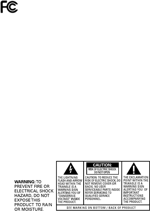
FCC Compliance Statement
This device complies with part 15 of the FCC rules. Operation is subject to the
following 2 conditions: 1. This device may not cause harmful interference; 2. This
device must accept any interference received, including interference that may
cause undesired operation. Responsible party (contact for FCC matter only):
THOMSON Inc.
101 W. 103rd St.
Indianapolis, IN 46290 U.S.A.
iv
Safety
Using Equipment Safely - Handset
In order to understand the key features of your TH58 Handset, it is recommended
that you read this guide carefully, including all the safety instructions, before using the
product. It is recommended that you inform other members of your family (especially
your children) of the detailed warnings given in this guide.
When your Handset is connected to the Internet, you may download software updates
for the base and handset. Applying these updates and the improvements they contain
may slightly modify the menus.
To clean your Handset, use an antistatic cloth.
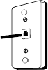
Telephone Jack Requirements
To use this phone, you need an RJ11C type modular
telephone jack, which might look like the one pictured here,
installed in your home. If you don’t have a modular jack, call
yourlocalphonecompanytondouthowtogetoneinstalled.
Phone Installation
Digital Security System
Your cordless phone uses a digital security system to protect against false ringing,
unauthorized access, and charges to your phone line.
INSTALLATION NOTE: Some cordless telephones operate at frequencies that may
cause or receive interference with nearby TVs, microwave ovens, and VCRs. To
minimize or prevent such interference, the base of the cordless telephone should
not be placed near or on top of a TV, microwave ovens, or VCR. If such interference
continues, move the cordless telephone farther away from these appliances.
Certain other communications devices may also use the 1.9 GHz frequency for
communication, and, if not properly set, these devices may interfere with each other
and/or your new telephone. If you are concerned with interference, please refer
to the owner’s manual for these devices on how to properly set channels to avoid
interference. Typical devices that may use the 1.9 GHz frequency for communication
include wireless audio/video senders, wireless computer networks, multi-handset
cordless telephone systems, and some long-range cordless telephone systems.
Important Installation Guidelines
Avoidsourcesofnoiseandheat,suchasmotors,uorescentlighting,•
microwave ovens, heating appliances and direct sunlight.
Avoid areas of excessive dust, moisture and low temperature.•
Avoid other cordless telephones or personal computers.•
Never install telephone wiring during a lightning storm.•
Neverinstalltelephonejacksinwetlocationsunlessthejackisspecically•
designed for wet locations.
Never touch non-insulated telephone wires or terminals, unless the telephone •
line has been disconnected at the network interface.
Use caution when installing or modifying telephone lines.•
Modular
telephone
line jack
Wall plate
v
Safety
Interference Information
This device complies with Part 15 of the FCC Rules. Operation is subject to the
following two conditions: (1) This device may not cause harmful interference; and (2)
This device must accept any interference received, including interference that may
cause undesired operation.
This equipment has been tested and found to comply with the limits for a Class B
digital device, pursuant to Part 15 of the FCC Rules. These limits are designed to
provide reasonable protection against harmful interference in a residential installation.
This equipment generates, uses, and can radiate radio frequency energy and, if not
installed and used in accordance with the instructions, may cause harmful interference
to radio communications. However, there is no guarantee that interference will not
occur in a particular installation.
Privacy of Communications may not be ensured when using this product.
If this equipment does cause harmful interference to radio or television reception,
which can be determined by turning the equipment off and on, the user is encouraged
to try to correct the interference by one or more of the following measures:
• Reorientorrelocatethereceivingantenna(thatis,theantennaforradioor
television that is “receiving” the interference).
• Reorientorrelocateandincreasetheseparationbetweenthe
telecommunications equipment and receiving antenna.
• Connectthetelecommunicationsequipmentintoanoutletonacircuitdifferent
from that to which the receiving antenna is connected.
If these measures do not eliminate the interference, please consult your dealer or an
experienced radio/television technician for additional suggestions. Also, the Federal
Communications Commission has prepared a helpful booklet, “How To Identify and
Resolve Radio/TV Interference Problems.” This booklet is available from the U.S.
GovernmentPrintingOfce,Washington,D.C.20402.Pleasespecifystocknumber
004-000-00345-4 when ordering copies.
NOTICE:Thechangesormodicationsnotexpresslyapprovedbytheparty
responsible for compliance could void the user’s authority to operate the equipment.
Hearing Aid Compatibility (HAC)
This telephone system meets FCC standards for Hearing Aid Compatibility.
Licensing
Licensed under US Patent 6,427,009.
FCC RF Radiation Exposure Statement
This equipment complies with FCC RF radiation exposure limits set forth for an
uncontrolled environment. This equipment should be installed and operated with
a minimum distance of 20 centimeters between the radiator and your body. This
transmitter must not be co-located or operated in conjunction with any other antenna
or transmitter.”
vi
Contents
Table of Contents
TechnicalSpecications i
Safety Recommendations ii
Using Equipment Safely - Gateway ii
Using Equipment Safely - Handset iv
Telephone Jack Requirements iv
Phone Installation iv
Digital Security System iv
Important Installation Guidelines iv
About your Advanced Cable Gateway 1
Key Features 1
Main Technical Characteristics 1
Computer Requirements 1
Before You Start 2
Box Contents 2
Become Familiar with Your Gateway and Handset 3
1. Gateway Front Panel 3
2. Gateay Rear Panel 4
3. Handset Overview 5
Layout 5
Setting up Your System 7
Install the Wi-Fi Card 8
Install the Gateway Battery 9
Install the Handset Batteries 10
Charge the Handset with the DC Adapter 11
DC Adapter Charging Method 11
Charge the Handset Docked to the Gateway 12
Connecting Cables 13
Connections Overview 13
Connect One or Two Computers with Ethernet Cables 14
Connect More Than Two Computers with Ethernet Cables 15
Connect Telephone or Fax with Standard Analogue Phoneline 15
Activate the Advanced Cable Gateway 16
Setup Wireless Access for Your Laptop, PC or Other Device 17
Becoming Familiar with Handset Operation 18
Day to Day Use 20
Making Calls 20
Receiving Calls 20
Ending Calls 20
Mute 21
Call Volume 21
Handset Screen Icons 22
vii
Contents
Access and Change Gateway Advanced Settings 23
Outline of Web Manager 24
Gateway – Status Web Page Group 25
1. Software 25
2. Connection 26
3. Password 26
Gateway – Telephony Web Page Group 27
1. Base 27
2. Handsets 27
Gateway – Router Web Page Group 28
1. LAN 28
2. WAN 29
3. Computers 29
4. Firewall 30
5. Forwarding 31
6. DMZ Host 33
Gateway – Wireless Web Page Group 34
Performance 34
Authentication 34
Security 35
1. 802.11b/g Basic 35
2. 802.11b/g Security 37
3. Access Control 39
eMTA settings – Basic Web Page Group 40
1. Status 40
2. CM Hardware 41
3. Event Log 41
4. CM State 42
Additional Information 43
Customize Your Handset 43
Chart of the Menus 43
1. Ring Tone 44
2. Time 45
3. Phone Settings 46
4. Call Lists 47
5. Using Your Phone With Multiple Handsets 48
Wiring Example 50
Frequently Asked Questions 51
Lights Guide 52
Troubleshooting 54
FCC Declaration of Conformity and Industry Canada Information 56
FCC Declaration of Conformity for Handset 57
Service Information 58
Glossary 59

viii
Safety
1
Introduction
Note:
The minimum requirements may vary among different cable companies.
About your Advanced Cable Gateway
Key Features
Thank you for choosing the ACG905, the new generation of Thomson
Gateways with enhanced functionalities. The Advanced Cable Gateway offers
the following services:
Multi-Line Capability, Up to 5 Handsets*•
Access to Voicemail, Address Book, News, Weather and other •
features via your Handset(s) - varies depending upon offerings from
your service provider
Built-in router functionality for home networking•
WiFi•
Main Technical Characteristics
DOCSIS 2.0 and PacketCable 1.5 Compliant•
Built-in DECT Technology•
Wireless (Add-On WiFi Card included)•
2 Ethernet Ports, 1 USB2.0 and 1 RJ11 Telephone Line•
Battery back-up•
Security Through Built-In Firewall and WEP, WPA, WPA2, BPI+ •
Protocols
Easy Access to Advanced Diagnostics Web Pages•
* Refer to page the Thomson Webpage URL for ordering information.
IBM PC COMPATIBLE MACINTOSH
CPU Pentium preferred Power PC
Operating
System Windows NT/2000/Me/XP/Vista, Linux Mac OS 10.4xor higher
Video VGA or better (SVGA preferred) VGA or better (SVGA built-in preferred)
Ethernet 10BaseT or 100BaseT 10BaseT or 100BaseT
An Ethernet card makes it possible for your computer to pass data to and from
the internet. You must have an Ethernet card and software drivers installed in your
computer. You will also need a standard Ethernet cable to connect the Ethernet
card to your Advanced Cable Gateway.
Software A TCP/IP network protocol for each machine Microsoft Internet Explorer 6.0 or
later or Mozilla Firefox.
Computer Requirements
For the best possible performance from your Advanced Cable Gateway, your
personal computer must meet the following minimum system requirements:
2
Parts and Putting them Together
Before You Start
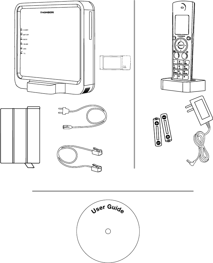
Box Contents
CAUTION
Advanced Cable Gateway
Battery
Rechargeable
Batteries
DC adapter for
DECT handset
Ethernet Cable
Power Cord
WiFi Card
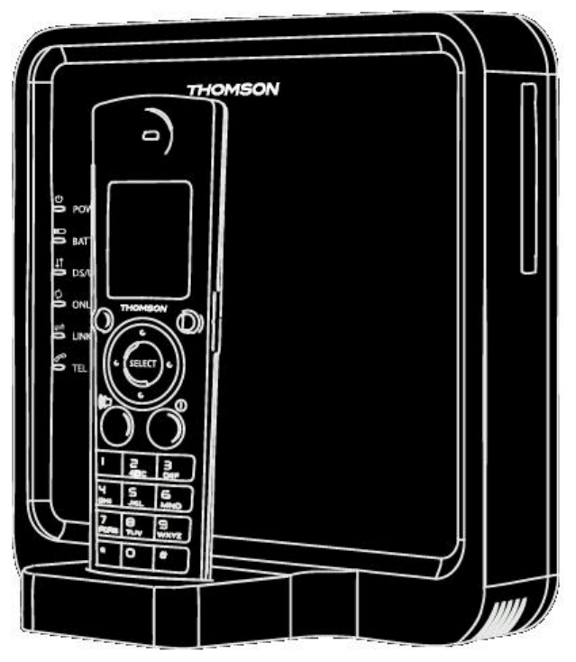
DECT handset TH-58 with Dock
User Guide on CD
3
Parts and Putting them Together
Become Familiar with Your Gateway and Handset
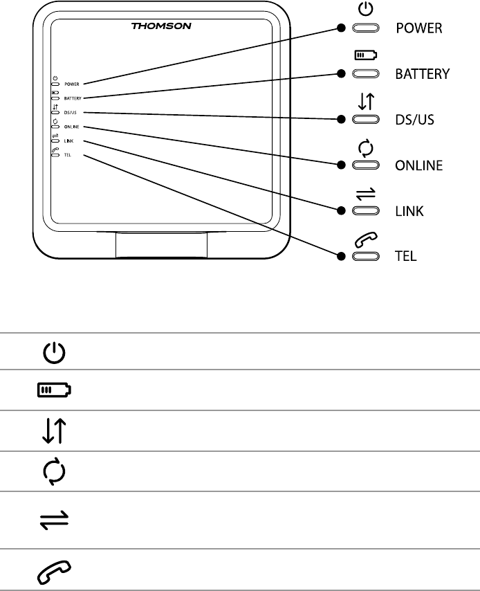
1. Gateway Front Panel
POWER Power
BATTERY Battery Back-Up Level
(low / full / empty or no battery detected)
DS/US Cable DOCSIS State;
LED ON during start-up operation
ONLINE Internet Active
LINK CPE Activity
LED ON when a PC is connected to the
Ethernet port
TEL Voice Over IP Information
4
Parts and Putting them Together
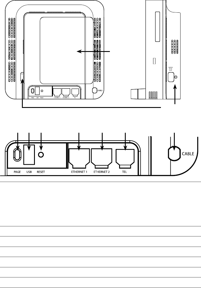
2. Gateay Rear Panel
Back-Up
Battery Cover
Power Input
Page USB RESET
120V AC. 60Hz, 0.5A
ETHERNET 1 ETHERNET 2 TEL CABLE
PAGE To ring all connected Handsets ( short press )
or
Add another DECT Handset to the Gateway ( press for more than
12 seconds )
or
Reset to factory settings ( press at power off; keep pressing for 5
seconds while powering on the Advanced Cable Gateway )
USB USB 2.0 Connector ( master )
RESET Reset ( short press )
ETHERNET 1 Ethernet 10/100 BaseT RJ-45 Connector
ETHERNET 2 Ethernet 10/100 BaseT RJ-45 Connector
TEL Telephone RJ-11 Connector
CABLE Cable Input; F-Connector
5
Parts and Putting them Together
Start
M
en
u
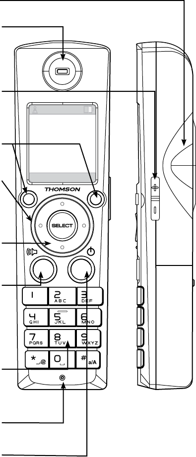
3. Handset Overview
Layout
Hands-Free Loudspeaker
Earpiece
Audio output for telephone calls.
Side Key
Use the up and down key of
the side button to increase or
decrease the listening volume
Left & Right Softkey
(described on page 18)
Color Ring
(outside perimeter of NavKey)
Displays differing color lights
as incoming calls & messages
are received
NavKey
(Navigation Key)
(described on page 18)
Talk Key (Green Key)
Press this key to get a dial tone.
After pre-dialing a number, press
to make a call.
Press to answer “call waiting”.
Press to activate the
Hands-Free function.
Keypad
These keys are used for dialing
phone numbers or entering text.
(See additional description on page 19)
Microphone
Audio input for telephone calls
OFF (Red Key)
(described on page 18)

6
Parts and Putting them Together
7
Set-up
Setting up Your System
These are the steps to set up your system. They are described step by step
in detail on the following pages; so, when you are ready, turn the page to get
started. . .
Basic Set-up
Step 1: Install the WiFi Card 8
Step 2: Install the Gateway Battery
(provides power should the electricity go out) 9
Step 3: Install the Handset Batteries 10
Step 4: Charge the Handset with DC Adapter 11
Step 5: Charge the Handset Docked to the Gateway 12
Step 6: Connect Cables
Connections Overview 13
Connect One or Two Computers with Ethernet Cables 14
Connect More than Two Computers with Ethernet Cables 15
Connect Telephone or Fax with Standard Analogue Phone Line 15
Step 7: Activate the Advanced Cable Gateway 16
Step 8: Set-up Wireless Access for Your
Laptop, Wireless PC or Other Device 17
Step 9: Become Familiar with the Handset Operation 18-22
Additional Options
Access and Change Gateway Advanced Settings 23-42
Customize Your Handset 43-49
Order Additional Handsets (up to 5 supported) visit www.tbd.com
8
Charging and Batteries
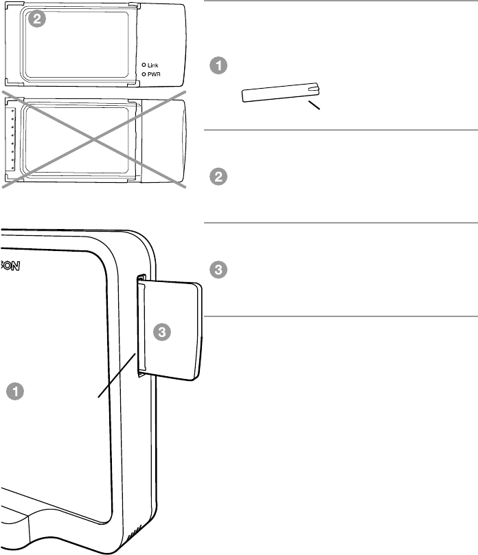
Install the Wi-Fi Card
The Advanced Cable Gateway is ready to support Wi-Fi and comes with a
card. Follow these instructions for installation:
Remove the protective cover over the
Wi-Fi slot located on the upper right
hand side of the Gateway.
Make certain that the front of the
Wi-Fi card is facing you.
Insert the Wi-Fi card in the slot as far
as it will go without forcing it.
Cover for Wi-Fi slot removed
WARNING: The Gateway must be unplugged from the wall socket before
you attempt to install the Wi-Fi card.
FRONT of WiFi card
(this side must face you
during insertion)
BACK
of WiFi card
Slot for Wi-Fi
with
cover removed
9
Charging and Batteries
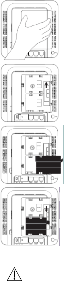
Install the Gateway Battery
Should the electricity go out, this will provide backup power to the Gateway:
Ensure the power cord is unplugged. 1.
Remove the battery cover on the
rear panel. There are two battery
compartments. One battery is included
with the Advanced Cable Gateway.
For an additional battery please contact
your local operator.
Push the slider up/down to allow for 2.
battery insertion.
Insert the battery into the compartment 3.
marked
“Battery 1”.
Readjust the slider to prevent the battery 4.
from moving and replace the battery
cover. Plug the power cord into an
electrical outlet that is not controlled by
a wall switch (this will assure that the unit
has uninterrupted power). The battery
will fully charge within 5 hours.
CAUTION: The use of a non-rechargeable or incompatible
batteries may damage the product and may be hazardous to health.
10
Charging and Batteries
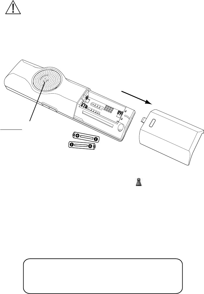
Install the Handset Batteries
NOTE: You must connect the handset battery before use.
Attention - special care
should always be taken with
the loudspeaker - never allow
anything to poke through or
pour into the holes. It is very
delicate.
CAUTION
NOTE: The RBRC seal on the battery used in your Thomson Inc. product
indicates that we are participating in a program to collect and recycle the
rechargeable battery (or batteries).
For more information go to the RBRC web site at www.rbrc.org
or call 1-800-8-BATTERY or contact a local recycling center.
CAUTION:Toreducetheriskofreorpersonalinjury,useonly
the Thomson Inc. approved Nickel-metal Hydride (Ni-MH) battery
model 5-2734, that is compatible with this unit.
Slide the battery door off the back of the Handset.•
Insert the batteries • (included) into the housing in the Handset being
careful to align the + / - ends correctly (refer to the graphics in the
housing).
Check that the screen lights up, then replace the cover.•
Wait for about 30 seconds to allow the system to start up.•
When your handset is registered to its base, •
the screen displays the number “1” alongside the (green - has signal)
symbol.
Battery Safety Precautions
Do not burn, disassemble, mutilate, or puncture. Like other batteries of •
this type, toxic materials could be released which can cause injury.
Toreducetheriskofreorpersonalinjury,useonlytheNickel-metal•
Hydride battery listed in the User’s Guide.
Keep batteries out of the reach of children.•
Remove batteries if storing over 30 days.•
11
Charging and Batteries
Changing the Battery
CAUTION:Toreduceriskofpersonalinjury,re,ordamageuse
only the 5-
2833
power adaptor listed in the user’s guide. This power
adaptorisintendedtobecorrectlyorientatedinaverticaloroor
mount position.
CAUTION
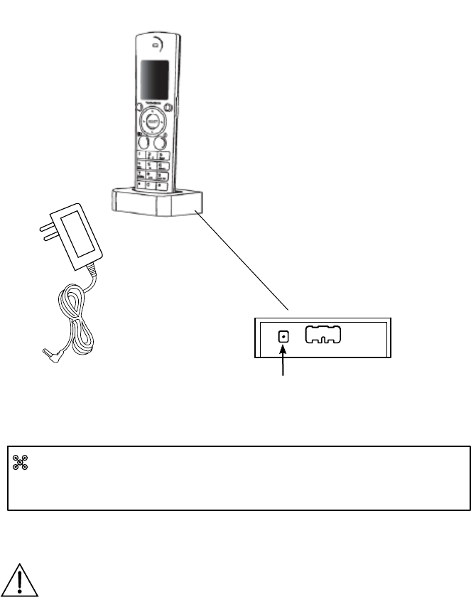
DC Adapter Charging Method
The DECT Handset dock can be
stationed away from the Advanced
Cable Gateway.
In this situation, be certain that the DC
adapter is attached to both the dock
and a power outlet.
Charge the Handset with the DC Adapter
The DECT Handset will charge when securely placed in the Handset Dock
so long as the dock has power.
The dock can charge your handset while attached to the front of the
Advanced Cable Gateway or by using the DC adapter included with the
Gateway.
DECT Handset
in its Dock
DC Adapter DC adapter connector
goes here
Back of Dock
Once installation is complete, you should leave the phone on the charger
for at least 5 hours before using it for calls and browsing content in order to
maximize battery performance and life.
12
Charging and Batteries
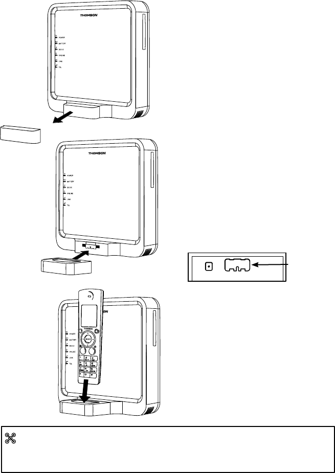
Charge the Handset Docked to the Gateway
In this situation, the Advanced Cable Gateway will be charging your handset.
To plug your DECT Handset Dock on the Gateway, follow the instructions
below:
Dock snaps
onto front of
ACG here
Back of Dock
Once installation is complete, you should leave the phone on the charger
for at least 5 hours before using it for calls and browsing content in order to
maximize battery performance and life.
Be certain that the power 1.
cord to the Advanced Cable
Gateway is unplugged.
Remove the Gateway’s Cover 2.
on the front panel.
Attach the DECT Handset 3.
Dock where the cover was.
Place the Handset into its 4.
receptacle on top of the Dock.
Handset Dock
ACG Cover
13
Connect Cables
Important Information:
Your cable company should always be consulted before installing a new
cable outlet.
Do not attempt any rewiring without contacting your cable company rst.
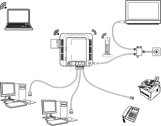
Connecting Cables
Connections Overview
computer (1)
computer (2)
analog
phone
fax
cable
splitter
TV
Wi-Fi card
Handset
with
dock
Telephone
Connections
Cable
Connections
Ethernet
Connections
RF
RF
RJ-45
RJ-45
RJ-11
Advanced
Cable
Gateway
Wi-Fi computer
Wireless
Connections
14
Connect Cables
computer (2)
computer (1)
wall
outlet cable
connection
RF
RJ-45
RJ-45
Advanced
Cable
Gateway
Handset
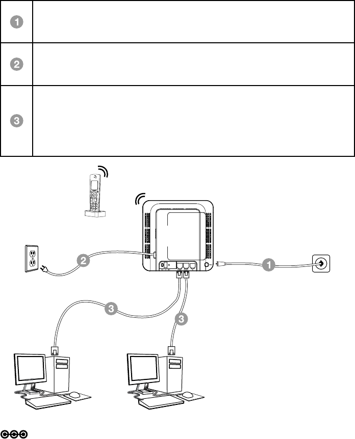
Connect One or Two Computers with Ethernet Cables
Make the connections to the modem in the following sequence:
Connect one end of the coaxial cable to the cable connection on the
wall, and the other end to the CABLE connector on the Advanced
Cable Gateway.
Connect one end of the power cord into the 120V, 60Hz, 0.5A socket
on the Advanced Cable Gateway and the other end into the power
plug in the wall.
Connect one end of the Ethernet cable (straight-wired, see below) to
the Ethernet port on the back of your computer and the other end to
the ETHERNET port on the Advanced Cable Gateway.
Note: The Gateway is equipped with two Ethernet ports, making
additional equipment unnecessary.
Note: Make sure that the Ethernet cable is straight-wired (not “null” or
crossover-wired).
However, you will need a crossover-type cable if you are connecting the
Gateway to a hub or a hub within a port switch that provides the same
function.
15
Connect Cables
Connect one end of the coaxial cable to the cable connection on the
wall, and the other end to the CABLE connector on the Advanced
Cable Gateway.
Connect one end of the power cord into the 120V, 60Hz, 0.5A socket
on the Advanced Cable Gateway and the other end into the power
plug in the wall.
Connect one end of the Ethernet cable (straight-wired, see below) to
the Ethernet port on the back of your computer and the other end to
the ETHERNET port on the Advanced Cable Gateway.
Note: The Gateway is equipped with two Ethernet ports, making
additional equipment unnecessary.
If you want to create hard wired connections to the ACG for more than
two computers, you will need to purchase a Hub (Switch) for that purpose
and the cabling necessary for those additional connections. Although a
10BaseT Hub or Switch can be used, it is not recommended. A 100BaseT
Hub or Switch is recommended. Follow the installation guidelines that
accompany this equipment.
Connect More Than Two Computers with Ethernet Cables
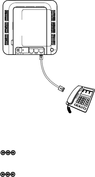
Connect Telephone or Fax with Standard Analogue Phoneline
When properly connected, most telephone devices can be used with the
Advanced Cable Gateway. Here is how to make that connection
Note: If you have any questions concerning telephone connection, please
contact your service provider.
Note: There is only one TEL connection available on the rear panel of the
Gateway.
analog
phone
Advanced
Cable
Gateway
Connect a standard phone line cord
directly from the phone (fax machine,
answering machine, caller ID box,
etc.) to the TEL port on the Gateway.
To make a normal telephone call,
pick up the handset; listen for a dial
tone, then dial the desired number
using this new connection. For
services such as call waiting, use
the hook switch (or FLASH button)
to change calls.
16
Activating Services
Activate the Advanced Cable Gateway
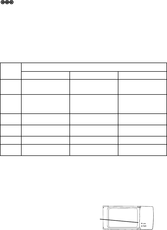
Wi-Fi Light Indicators on the Front Side of the Card
After the WiFi card is inserted and the Advanced Cable Gateway is plugged
back into the power outlet, you will know that the connection is successful
when the PWR LED on the front of the Wi-Fi Card shows a green light.
Also,whenyourstturntheGatewaybackon,theLink LED will blink a green
light - fast; when the card connects to the network sucessfully,
it will blink - slowly.
LED
label
Steady State Operation
ON OFF FLASH (Blinking)
Power AC Power Good with
Good/Low/Bad Battery
AC Power Failure with
Bad Battery
AC Power Failure with
Good Battery/Low Bat-
tery
Battery AC Power Good/
Good Battery
AC Power Good/
Bad Battery
AC Power Failure/
Good Battery/Bad Battery
AC Power Good/
Low Battery
AC Power Failure/
Low Battery
DS/US Normal AC Power Failure Initialization OR
Error (if Blinking persists)
Online Normal AC Power Failure Initialization OR
Error (if Blinking persists)
LINK Ethernet/Wi-Fi Link No Ethernet/Wi-Fi Link Ethernet/Wi-FiTrafc
Tel All Lines Good Telephone lines(s) not
avialable
One or More Telephones
Off hook
WiFi Card LEDs
Note: To activate your advanced cable gateway, please consult the
activation instruction provided by your service provider.
After installation of the Gateway, each time you turn it on (each time the modem is
reconnected to the power), it goes through several steps before it can be used.
Each of these steps is represented by a different pattern of ashing lights on the
front of the modem.
IfDS/US,ONLINE,andLINKledsashsimultaneouslyitmeanstheGatewayis
automatically updating its system software. Please wait for the lights to stop
ashing. You cannot use your modem during this time. Do not remove the power
supply or reset the Gateway during this process.

17
Activating Services
Setup Wireless Access for Your Laptop, PC or Other Device
Wi-FionyouAdvancedCableGatewayispreconguredwithanetworkname
(SSID) and WPA key (a security password to prevent others access to your
wireless network). This information is printed on the label on the outside of
your Gateway as shown in the following diagram:
In order to take advantage of the Wi-Fi connection available to you with
the Gateway you will need to setup your computer. Setup will be different
depending on the year, brand, model and installed software of your
computer. Please follow the instructions received with you computer that
explain how to connect to a wireless network. If you are using a recent
version of Microsoft Windows, one of the following methods may apply
(consult your computer/laptop instructions if one of these methods does not
work)
Method 1:
Click on “Wireless” icon in the bottom right hand portion of your •
screen
Select,”View Wireless Networks”•
Highlight “SSID” from the list and press “Connect”•
When prompted, enter the WPA key twice and press “Connect”•
Method 2:
Go to “Start” - “Control Panel” - “Network Connections”•
Double click “Wireless Network Connections”•
Highlight “SSID” from the list and press “Connect”•
When prompted, enter the WPA key twice and press “Connect”•
Method 3:
Go to “Start” - “Network Connections”•
Double click “Wireless Network Connections”•
Highlight “SSID” from the list and press “Connect”•
When prompted, enter the WPA key twice and press “Connect”•
WPA
SSID
S/N 87003 - 8174B0018
E-MTA MAC@ 00D059E132E5
MODEL : ACG905--C
CM MAC@ 00D059E132E4
Rating: 120V AC, 60Hz, 0.5A
SSID: THOMSON-ACG-32E4
WPA key: ZZZZZZZZZZZZZ
HW version: 05
Made in China for THOMSON
FCC ID WBJ ACG905C001THFR
I.T.E.
17GM E198937