Thrane and Thrane A S 3715A TT-3715A User Manual E540
Thrane & Thrane A/S TT-3715A E540
UserManual.wiki
>
Thrane and Thrane A S
>
3715A User Manual
UseerManual.pdf
Navigation menu
Upload a User Manual
Namespaces
Wiki Guide
HTML
PDF
Info
Views
User Manual
Discussion / Help
Navigation
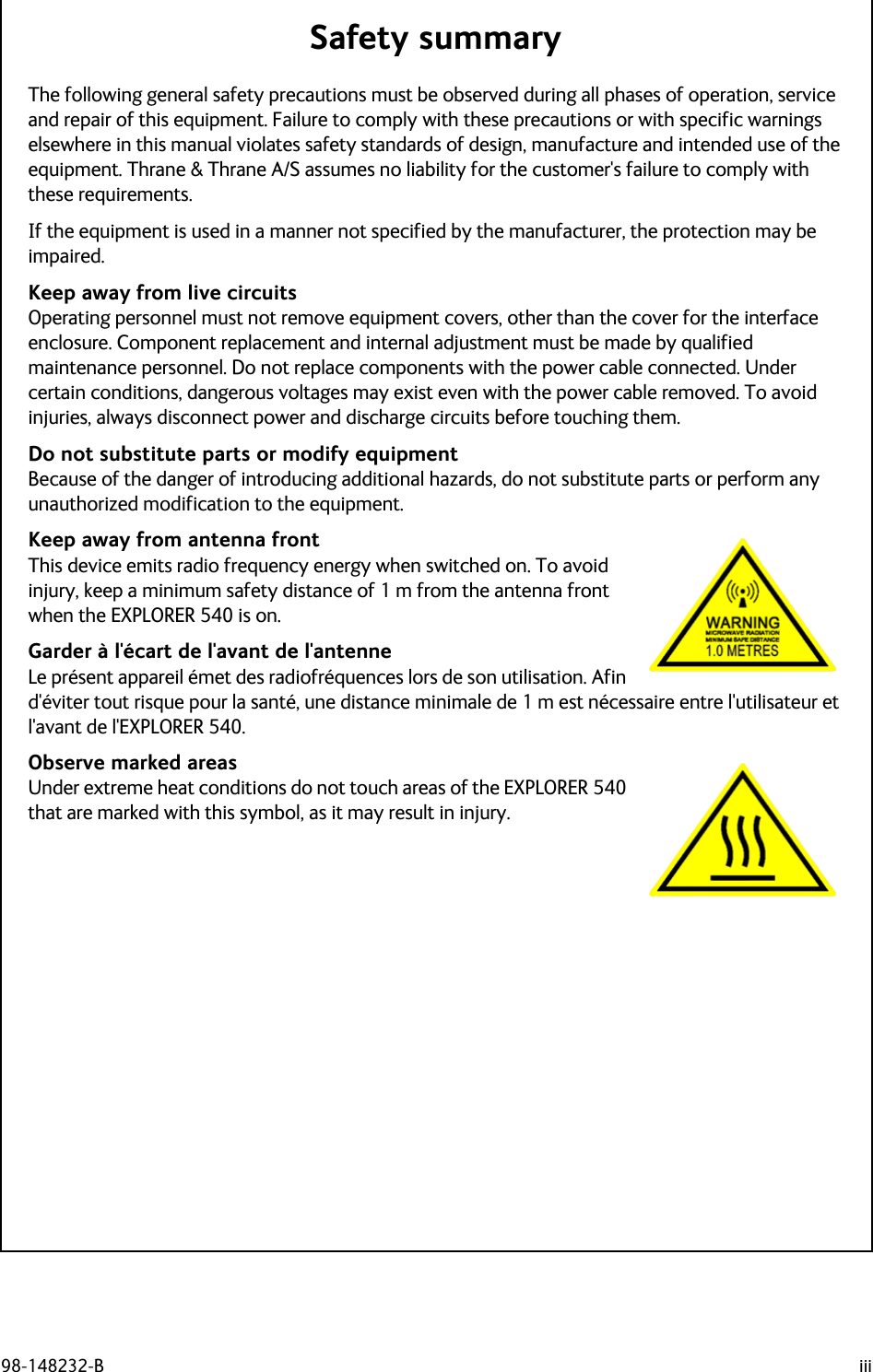
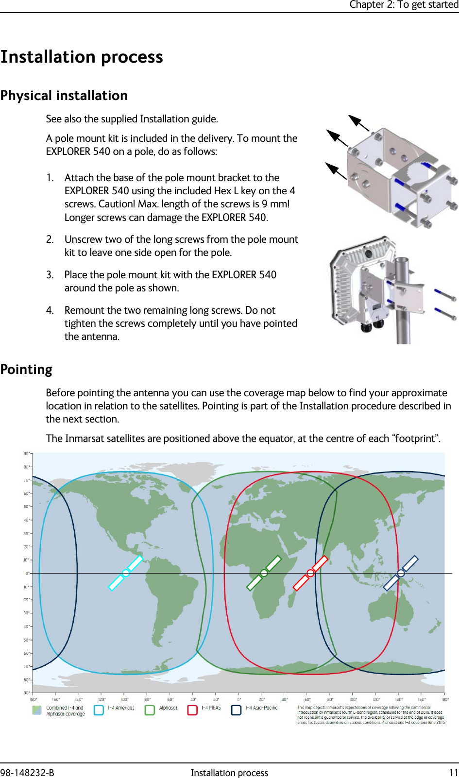
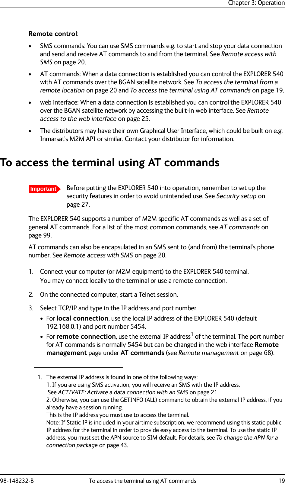
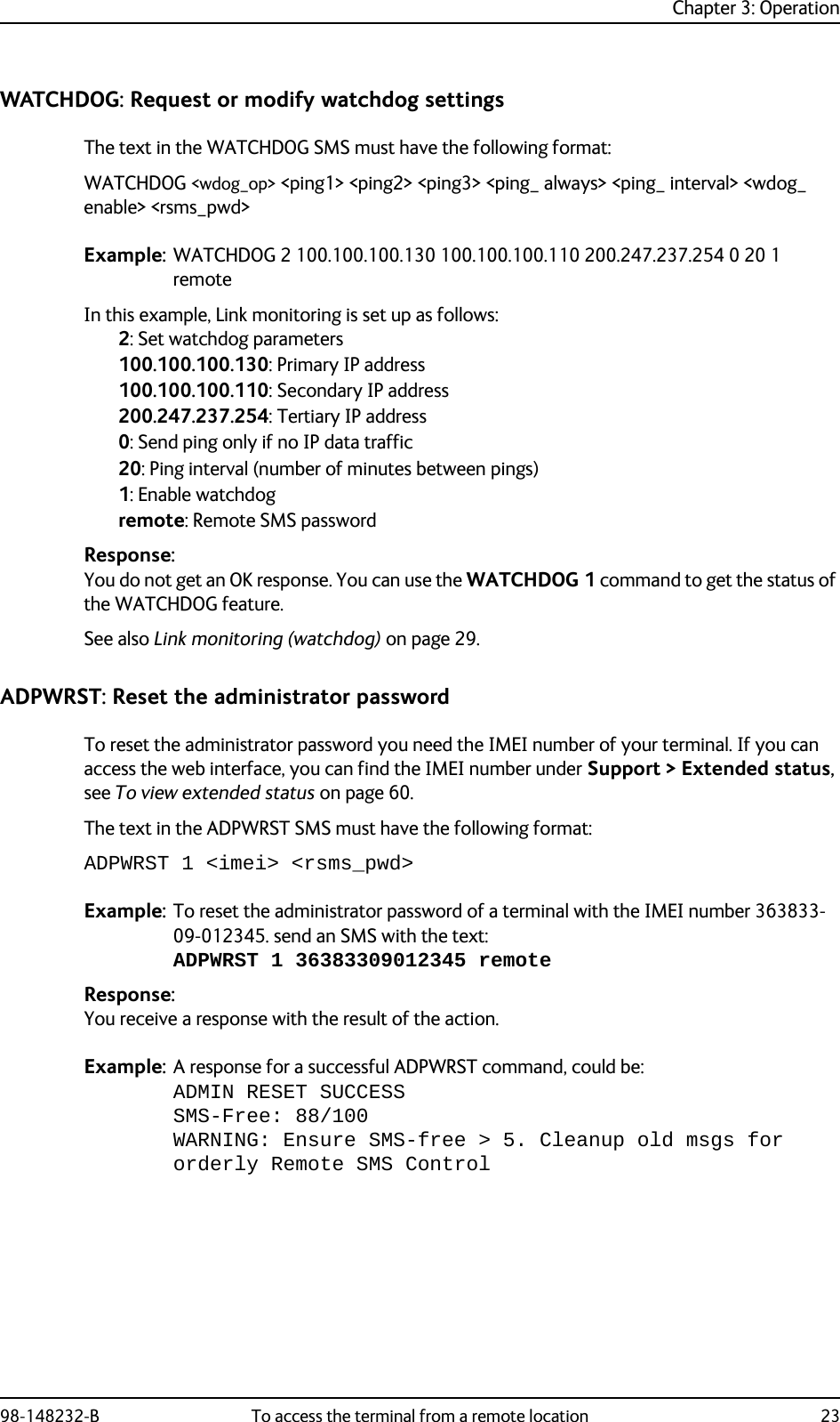
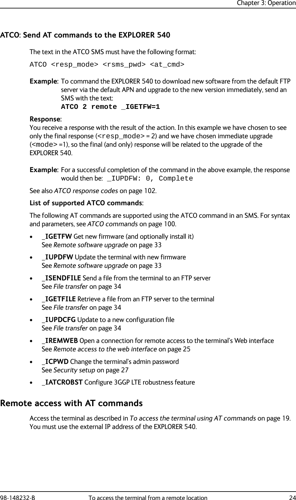
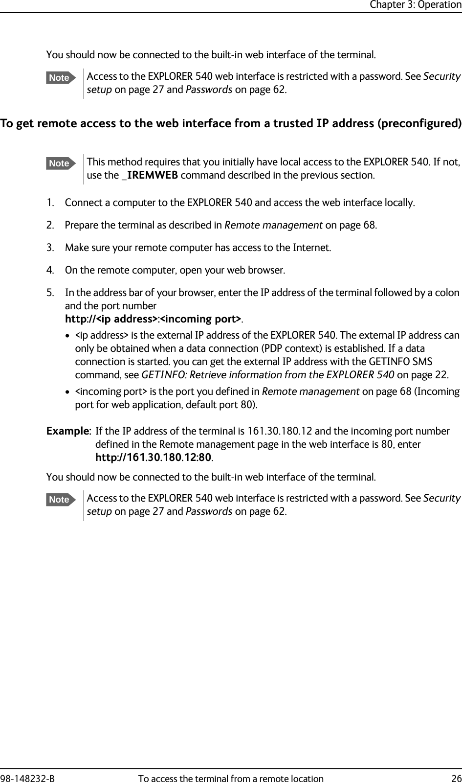
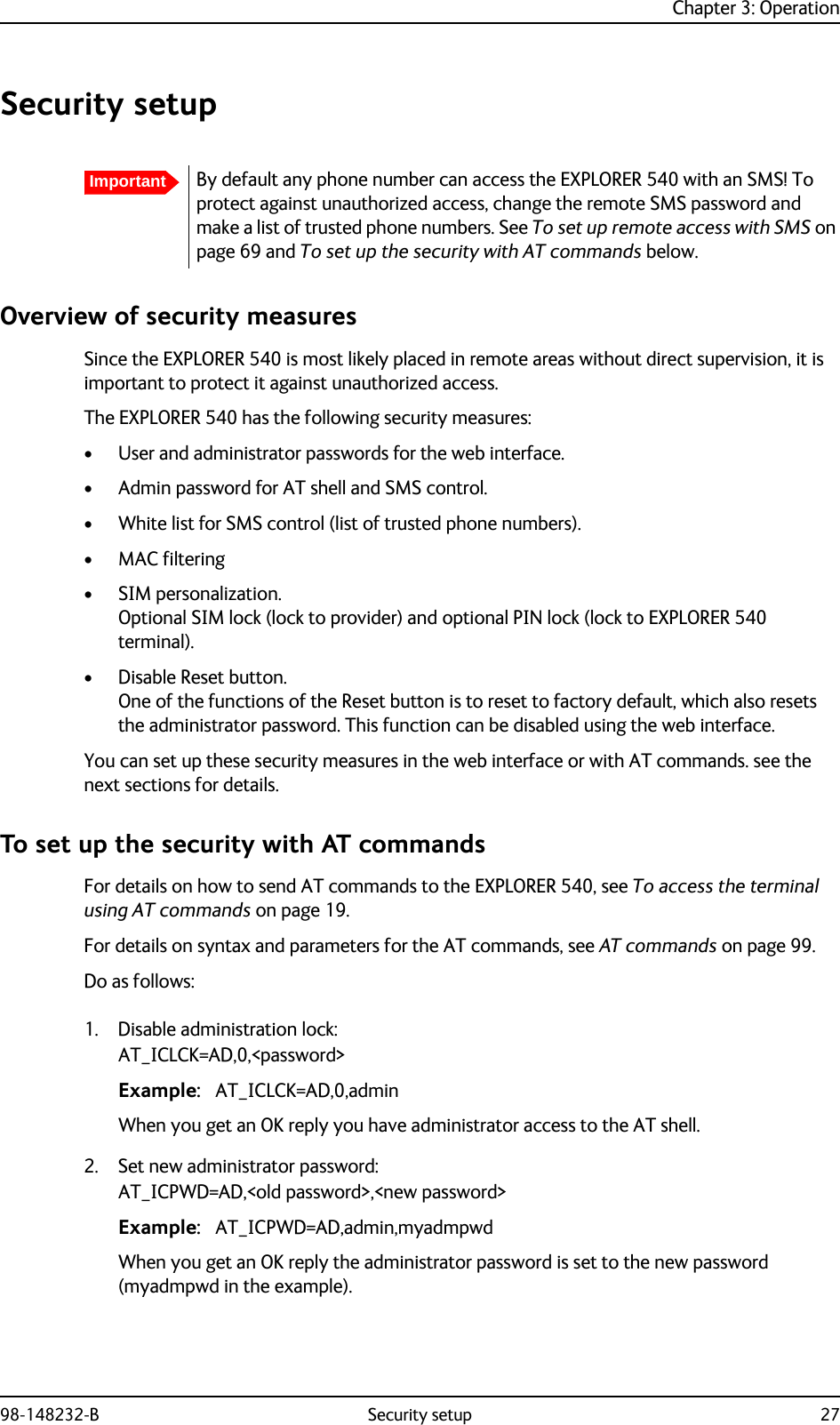
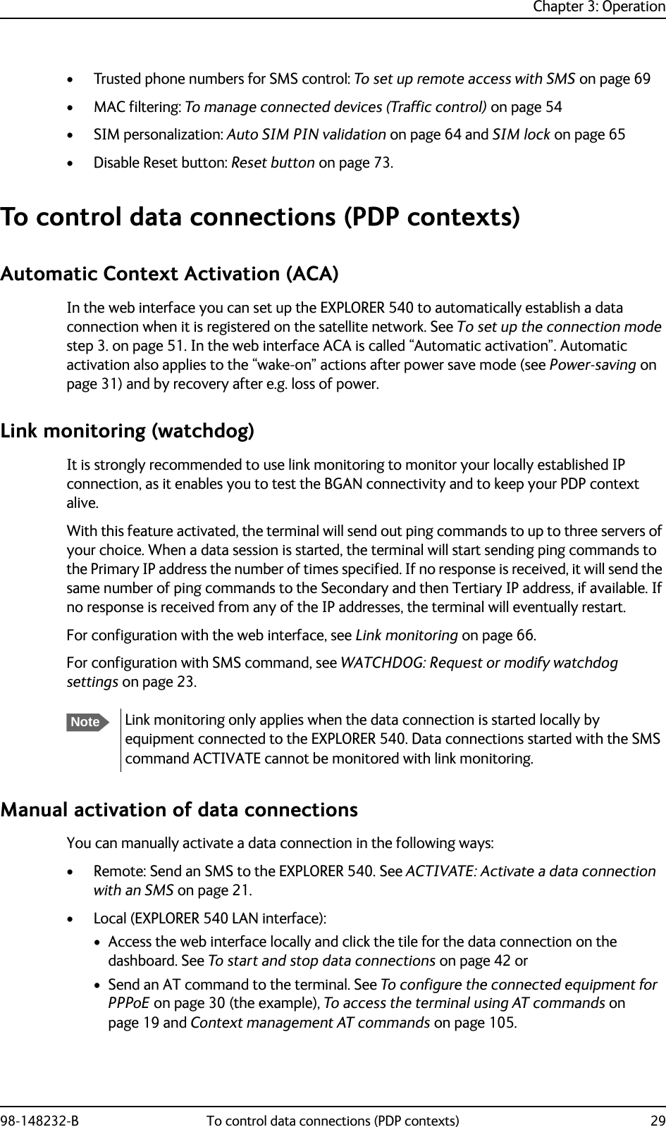
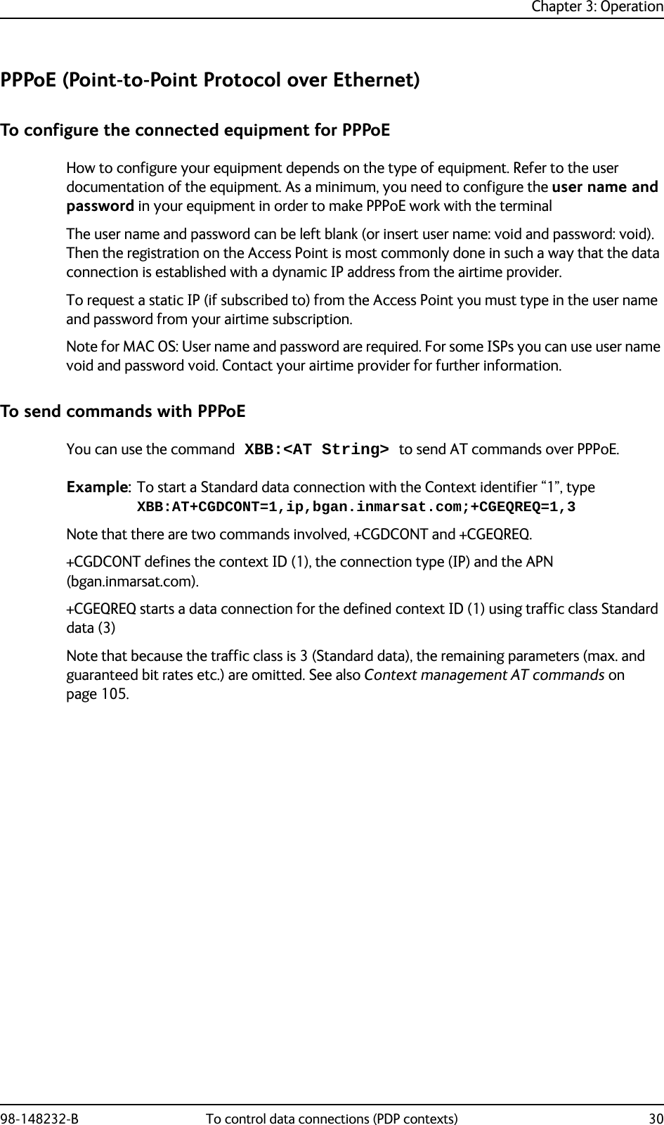
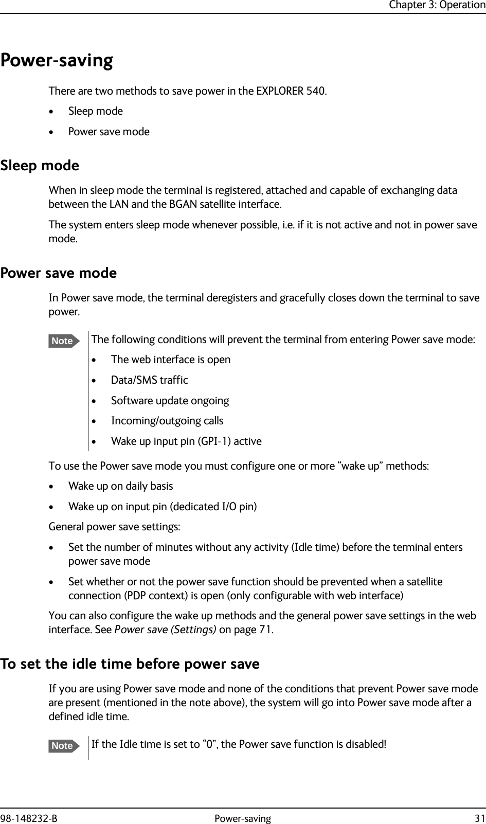
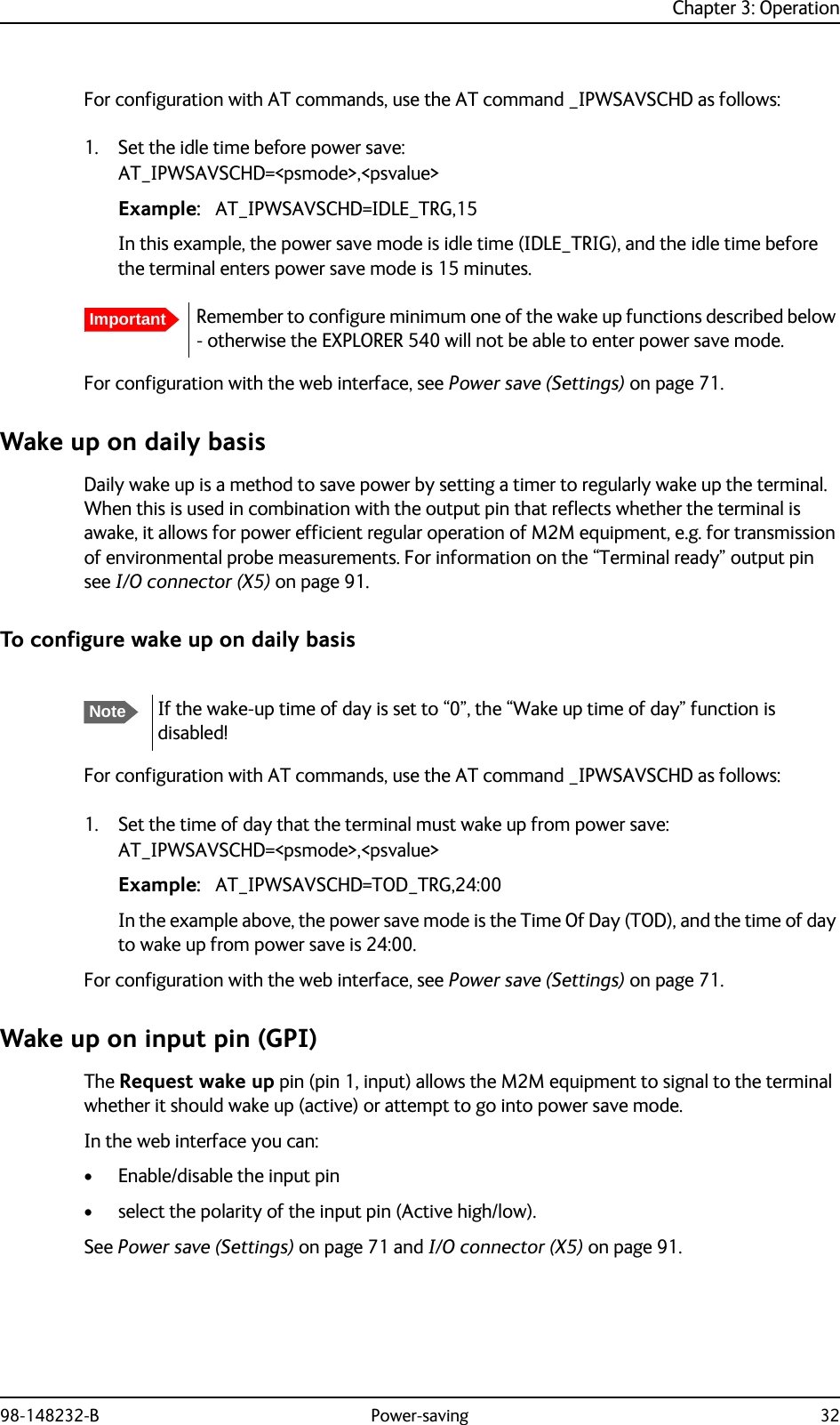
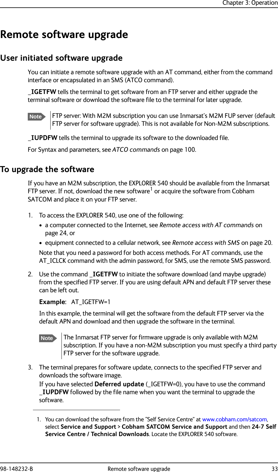
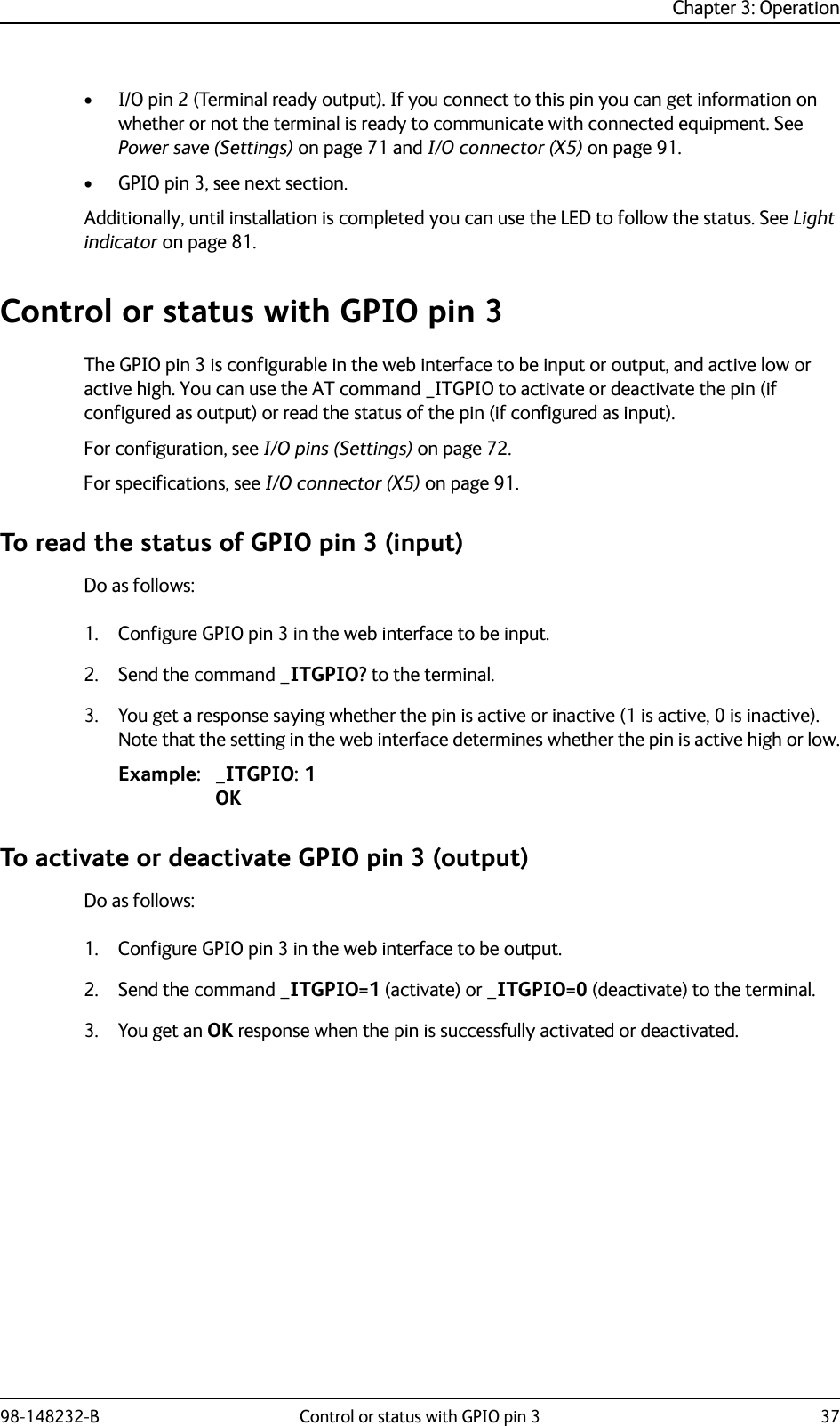
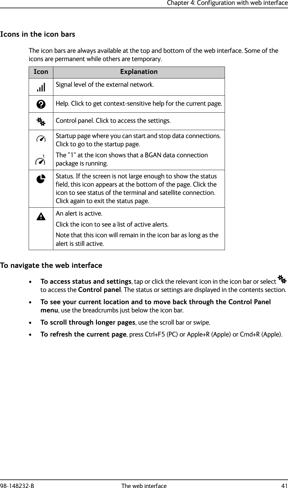
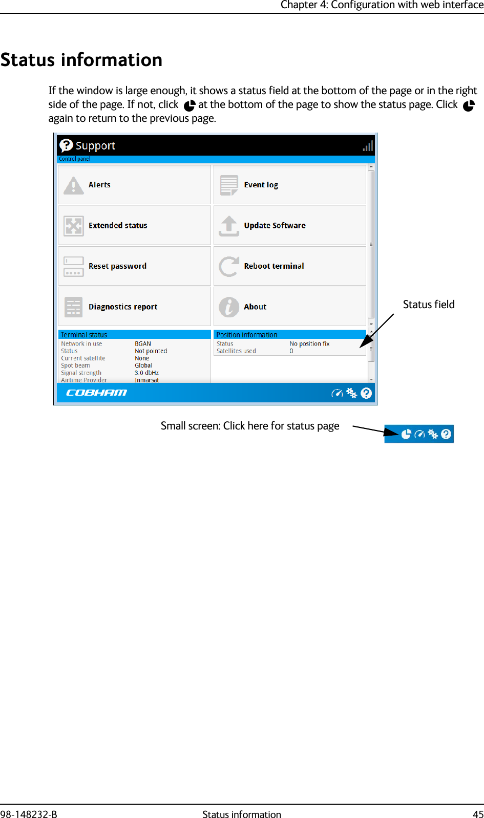
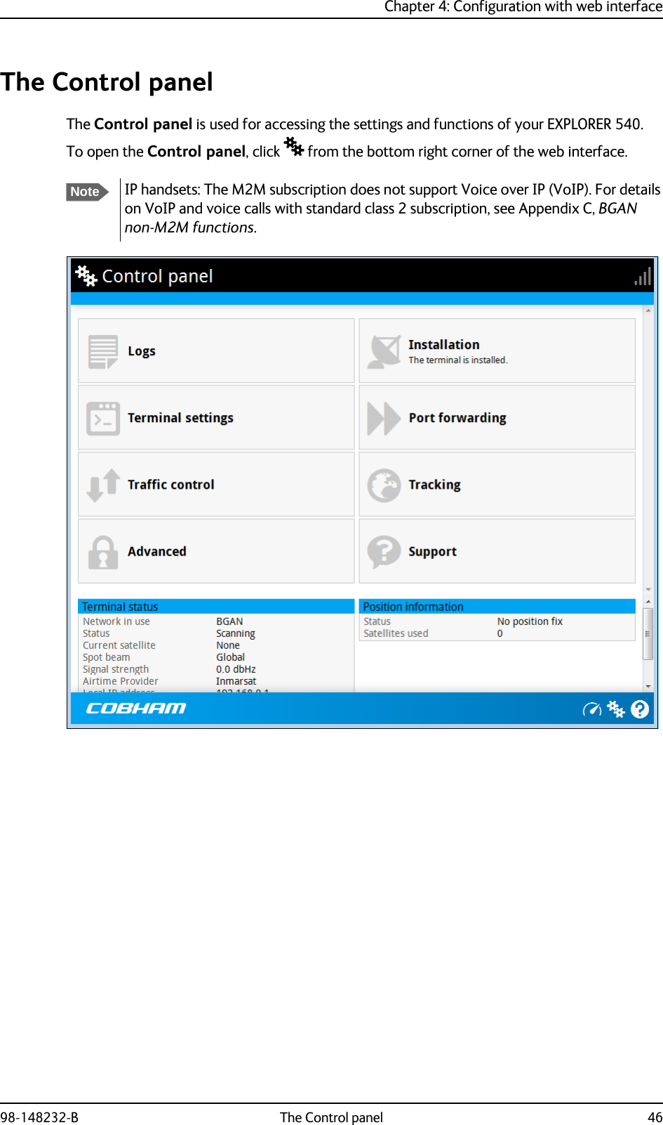
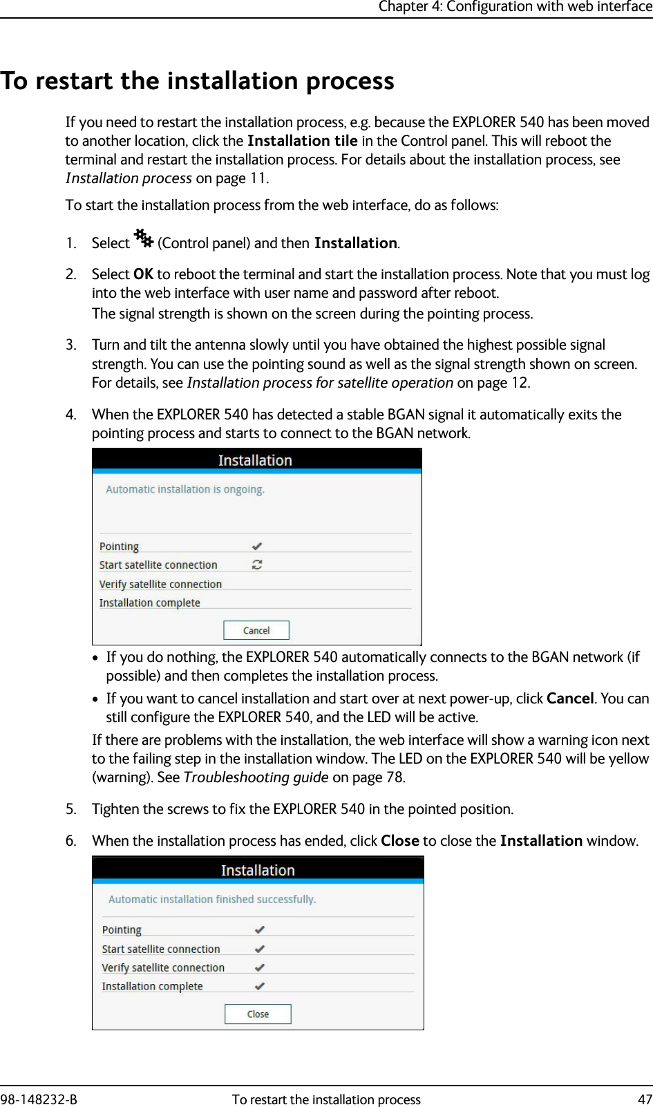
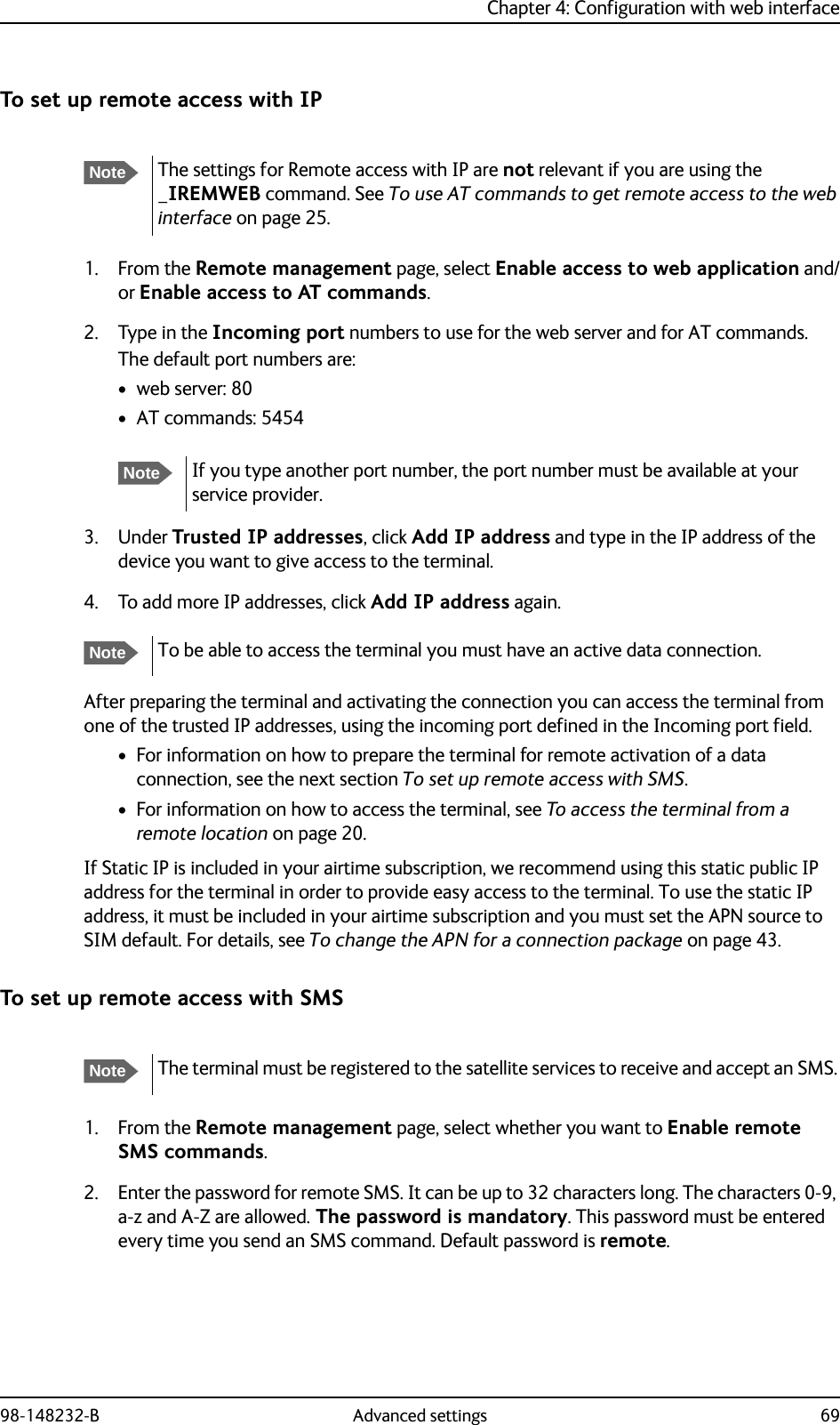
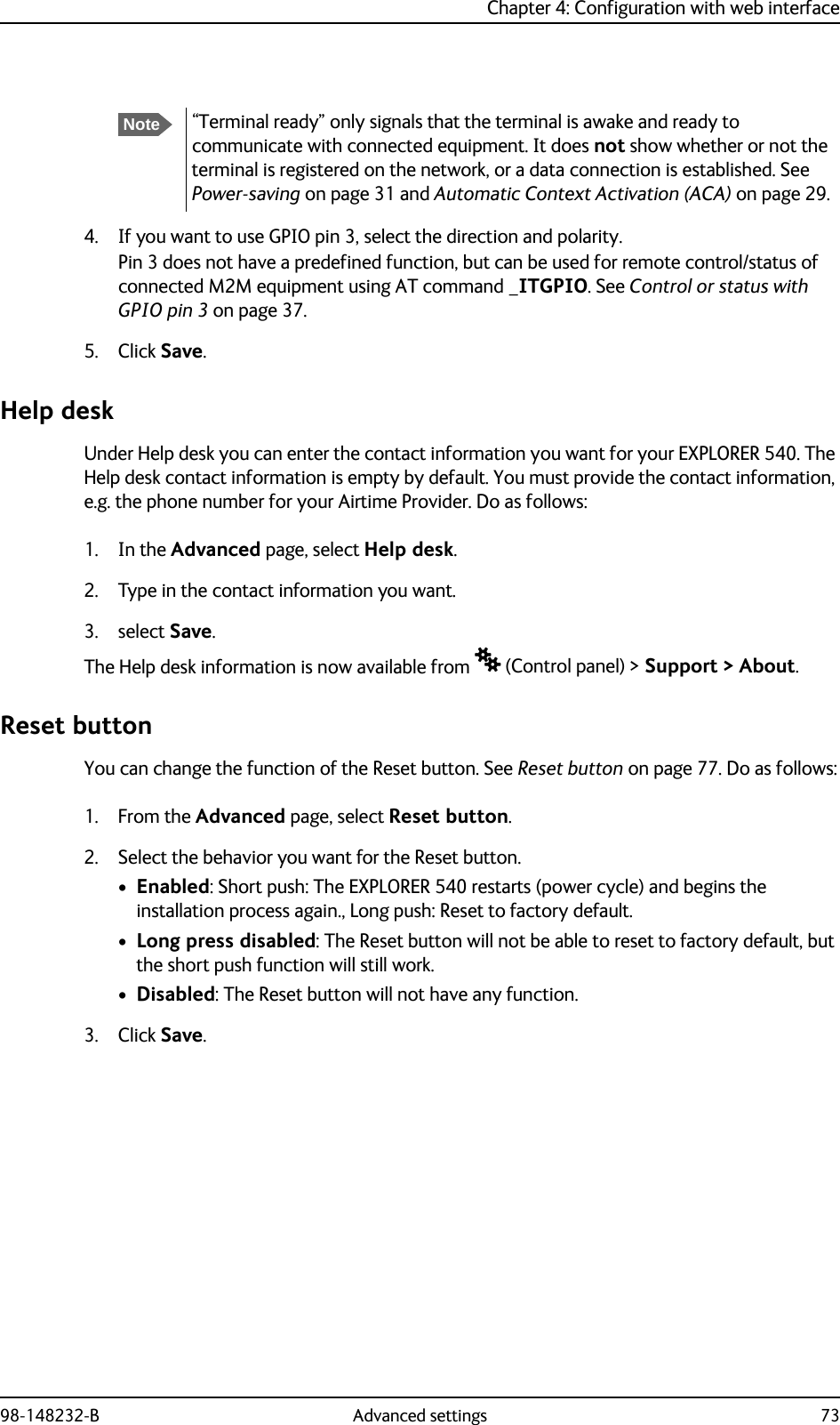
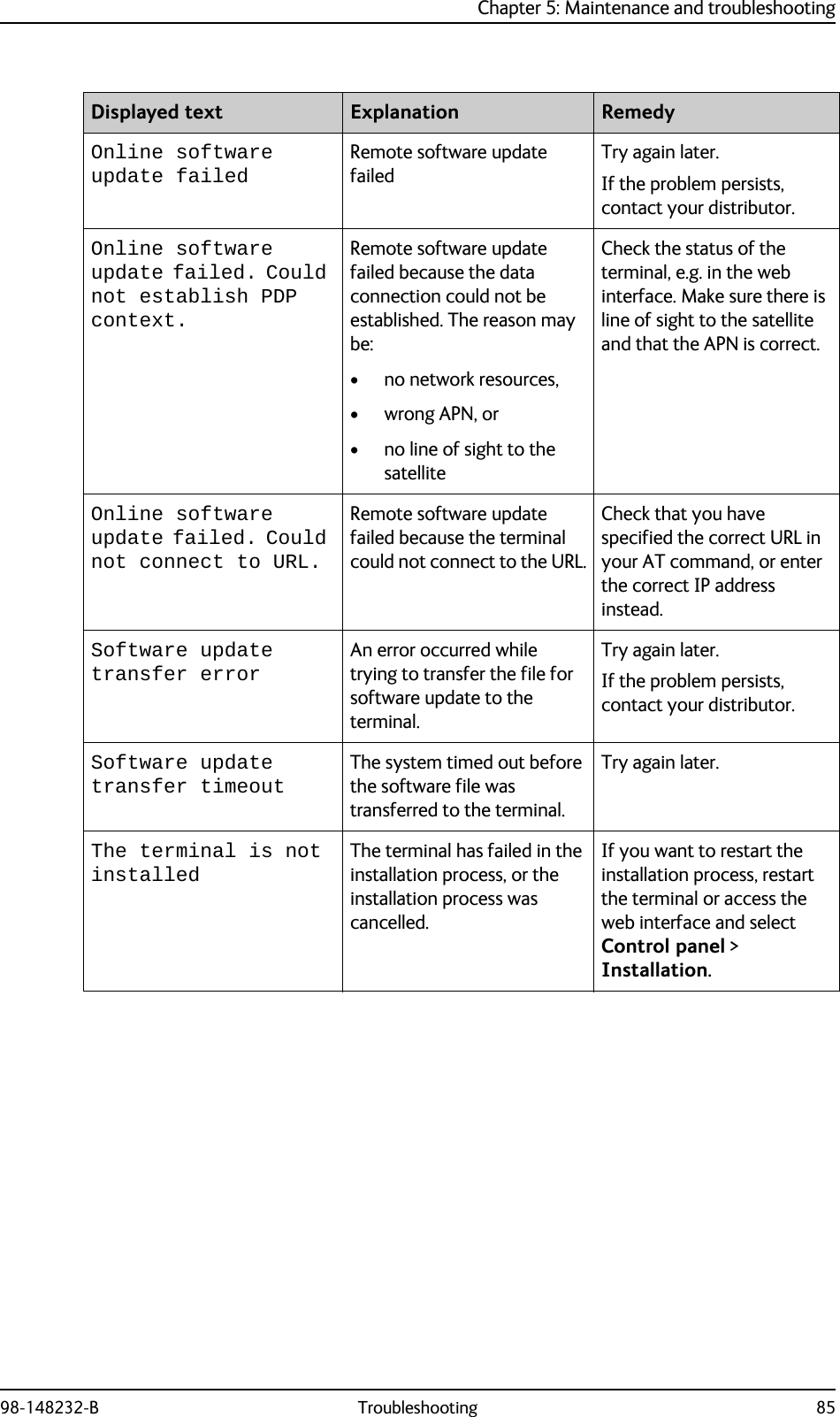
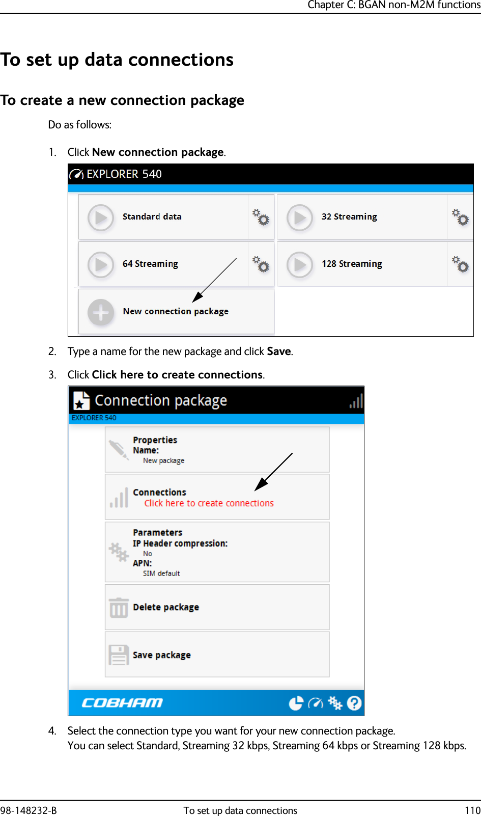
![Chapter 3: Operation98-148232-B To access the terminal from a remote location 25Remote access to the web interfaceThere are two methods of getting remote access to the web interface:• Using the AT command _IREMWEB, e.g. sent in an SMS (ATCO command)• Using an EXPLORER 540 that is pre-configured with trusted IP addressesThe following sections describe these two methods.To use AT commands to get remote access to the web interfaceYou can send the AT commands encapsulated in an SMS (ATCO commands). For details, see Remote access with SMS on page 20. Relevant commands:_IREMWEBSe ATCO commands on page 100 for syntax and parameters.1. To use an SMS to allow access to the web interface for specific IP addresses, send the following command:ATCO <resp_mode> <rsms_pwd> _IREMWEB=1,<ip address>[,<ip address>]Example: ATCO 2 remote _IREMWEB=1, 214.123.189.119In this example the command specifies no immediate response, only when the global IP address is sent along (2). The remote SMS password is remote and the IP address 214.123.189.119 can get remote access to the web interface (if two IP addresses are listed, it is interpreted as a range of IP addresses).2. The EXPLORER 540 should now return an SMS response with the external IP address of the terminal.Example: _IREMWEB:81, GlobalIP:161.30.181.3181 is the response code for a remote web connection that was set up successfully. It is followed by the global IP address, which is the IP address to enter in your browser to access the web interface from the remote device with the IP address you specified in the command.3. On the remote computer, open your web browser.4. In the address bar of your browser, enter the global IP address of the EXPLORER 540 (received in the response above).NoteWhen using remote access, the web interface may take a long time to load the pages, because the Internet connection may be slow.NoteOnly one PDP context at a time can be used for remote web interface access.NoteIf remote SMS command access has been disabled, you can enable it either using the web interface or using AT commands. See To set up remote access with SMS on page 69 and To set up the security with AT commands on page 27 (step 4.).](https://usermanual.wiki/Thrane-and-Thrane-A-S/3715A/User-Guide-2987760-Page-33.png)
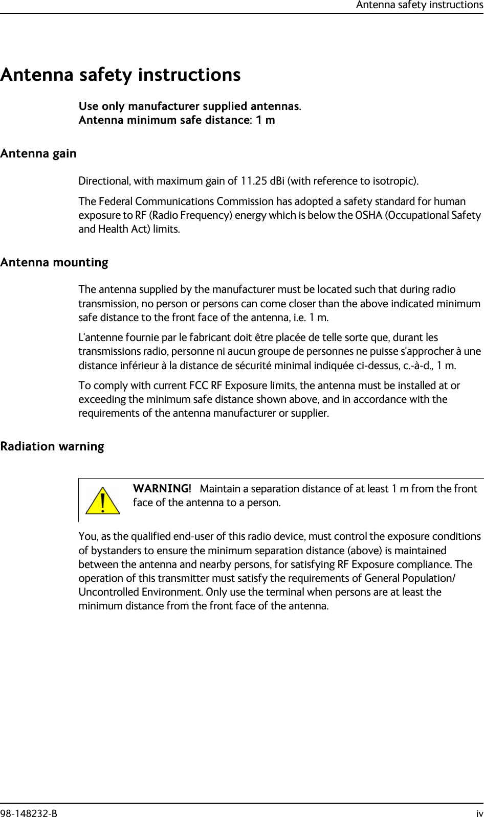
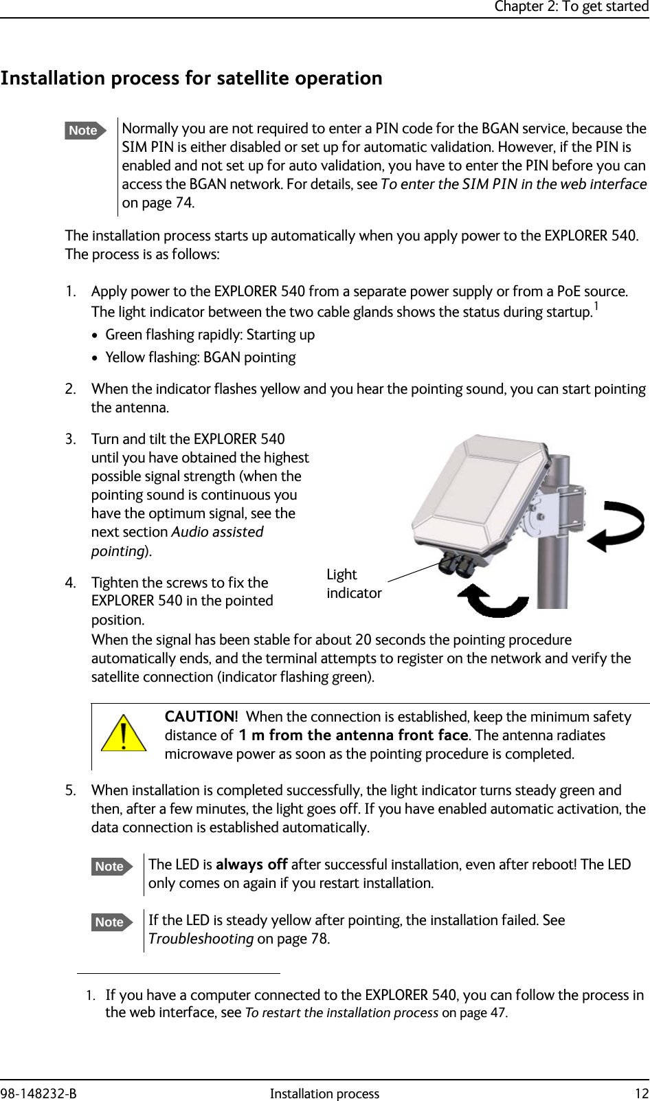
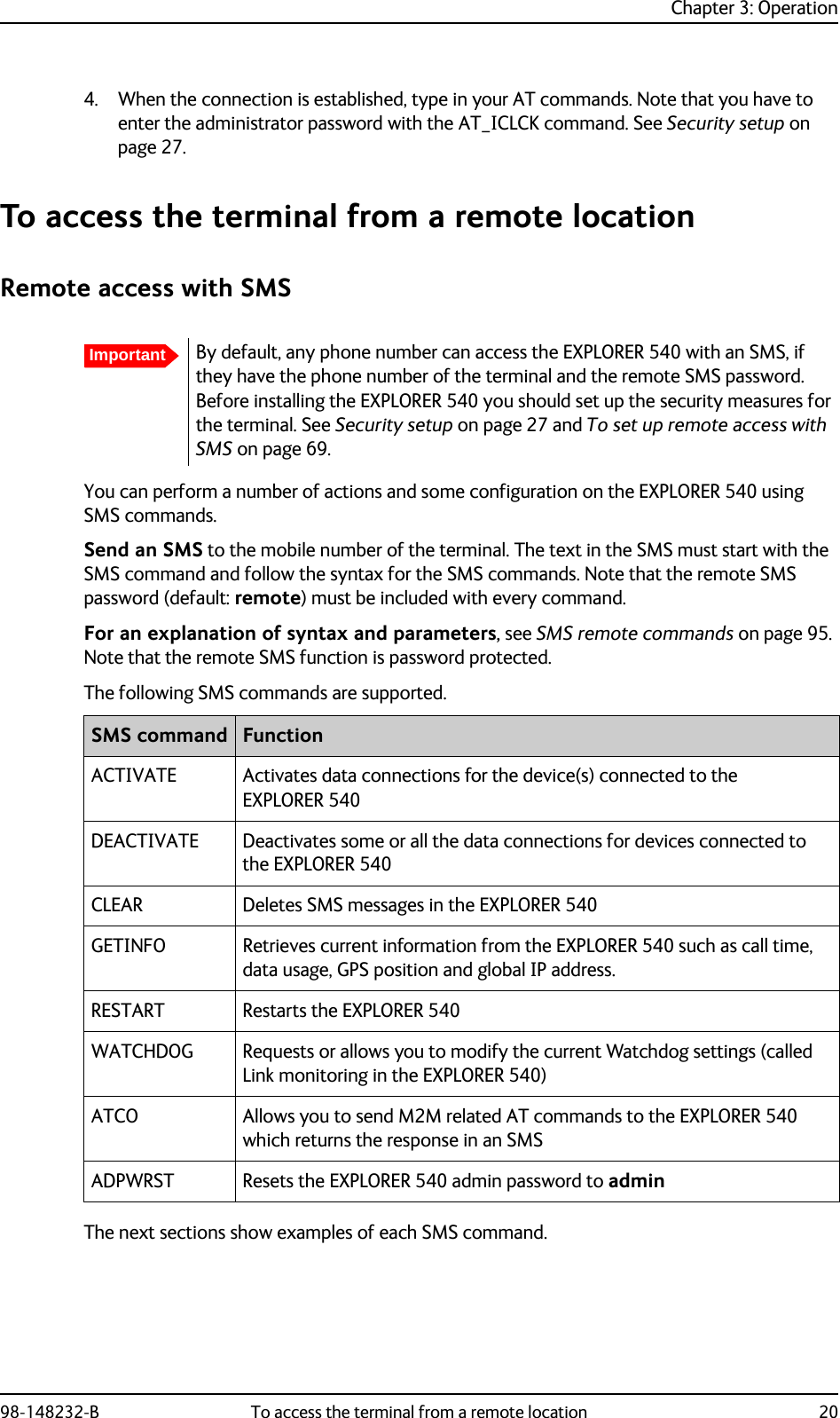
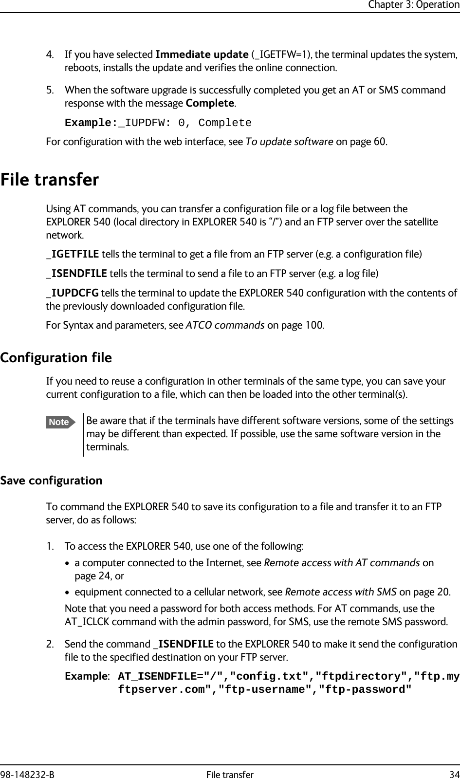
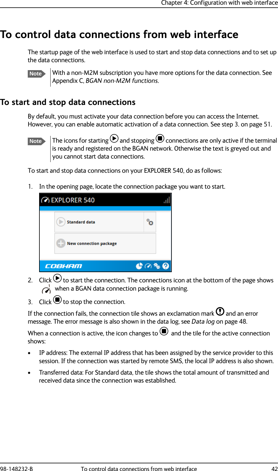
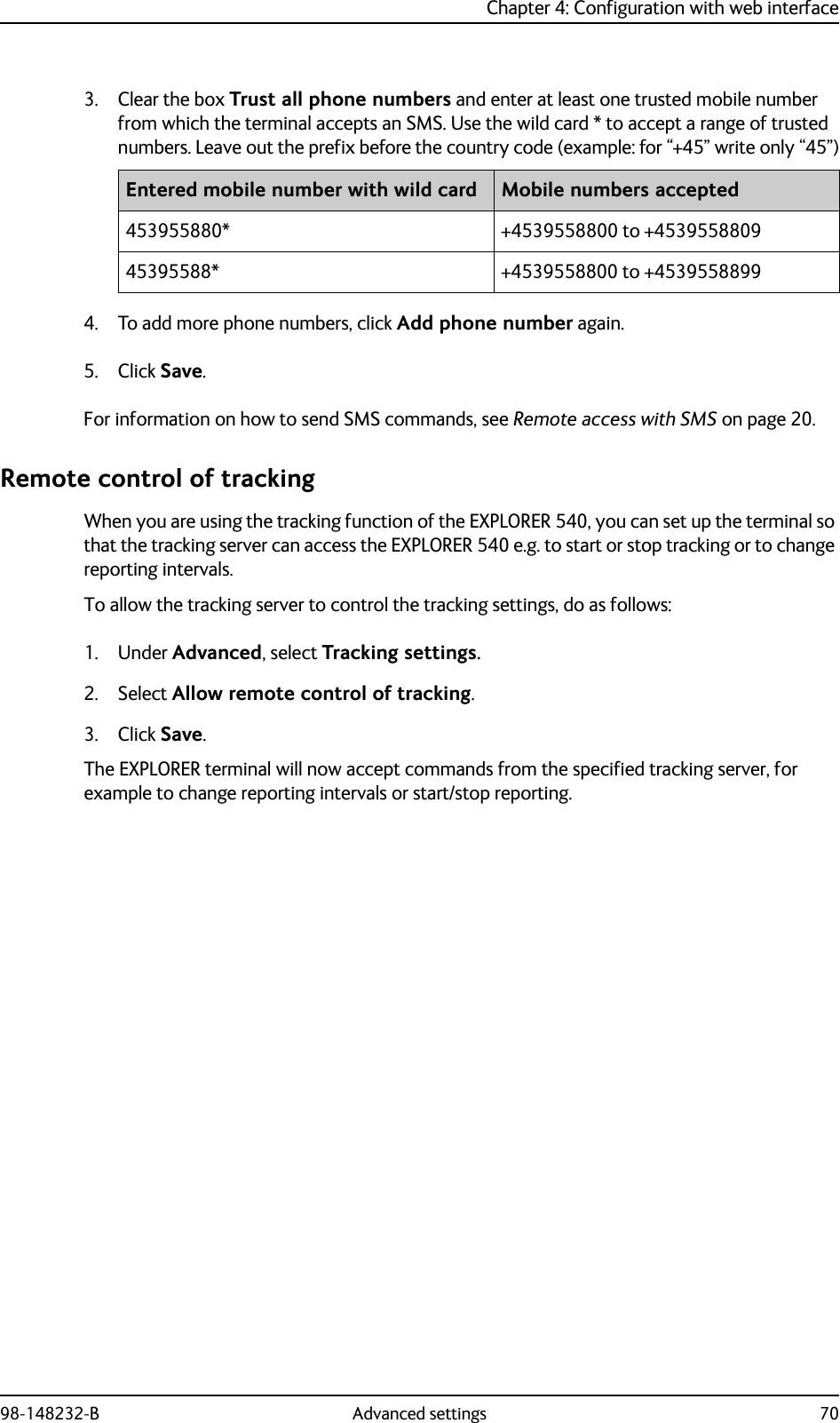
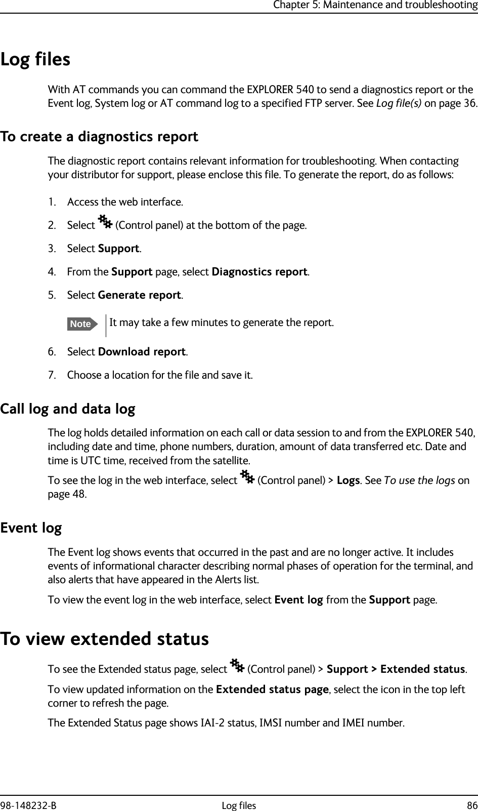
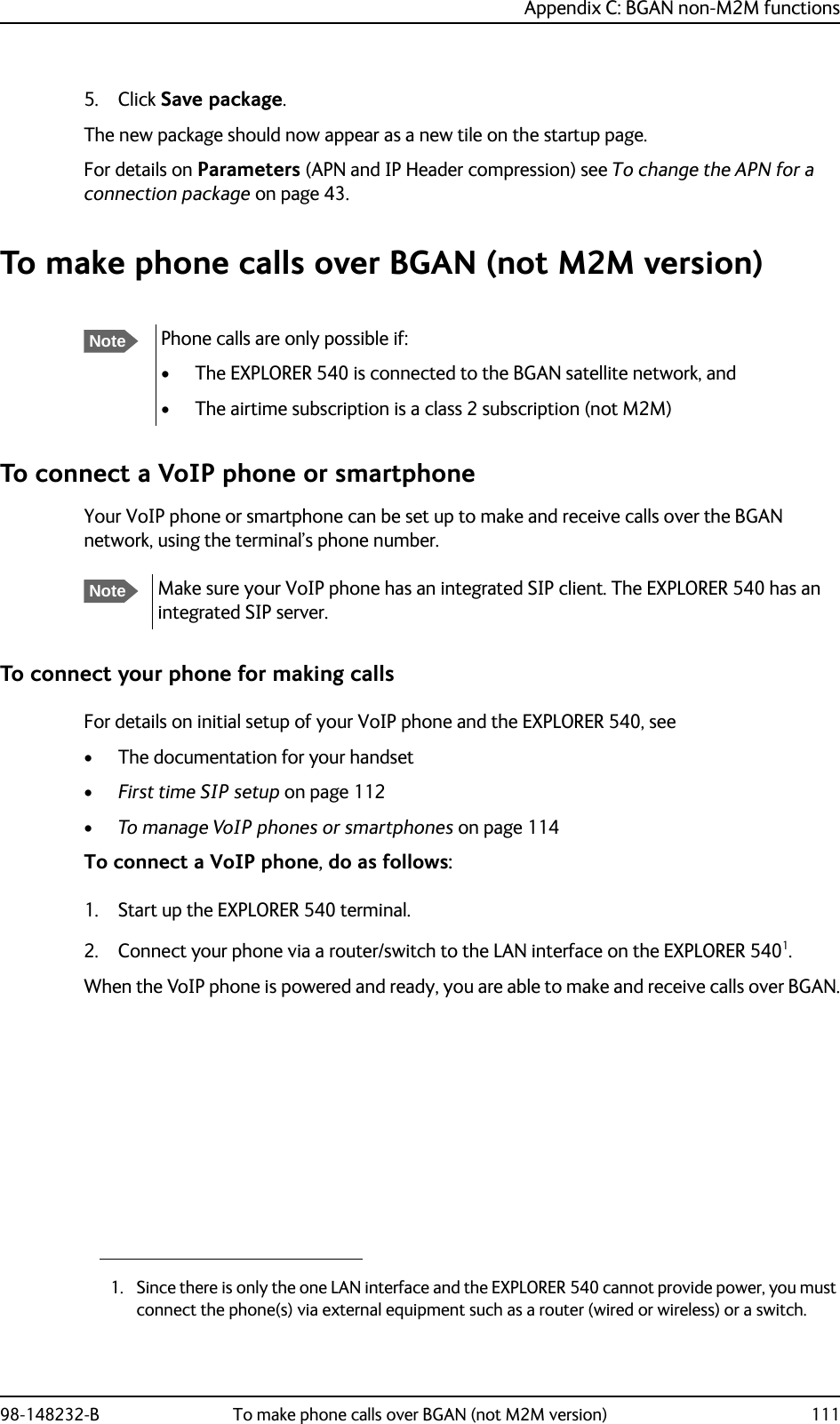
![Chapter 3: Operation98-148232-B Security setup 283. Set new password for remote SMS:AT_ICPWD=RS,<old password>,<new password>Example: AT_ICPWD=RS,remote,mysmspwdWhen you get an OK reply the password for remote SMS access is set to the new password (mysmspwd in the example).4. Disable/enable remote SMS commands:Disable: AT_ISMSRMT=0Enable: AT_ISMSRMT=15. Specify a white list of trusted MAC addresses:AT_IMACLOCAD=1,0,<MAC address>[,<MAC address> (etc.)]Example: AT_IMACLOCAD=1,0,00:B5:E0:76:FD:C2,00:B5:A0:84:F9:E2When you get an OK reply, the specified MAC addresses are added to the white list.6. Turn on MAC address filtering:AT_IMACLOC=1,0When you get an OK reply, MAC address filtering is enabled for Ethernet, and only the MAC addresses specified in the white list can get access (previous step). 7. Enable administration lock:AT_ICLCK=AD,1,<password>Example: AT_ICLCK=AD,1,myadmpwdWhen you get an OK reply, the system is protected with the administrator password.To set up the security with the web interfaceIf you want to setup the security with the web interface, see the following sections:• User and administrator passwords for web interface: Passwords on page 62• Admin password for AT shell (same as for web interface): Passwords on page 62• Password for remote SMS access: To set up remote access with SMS on page 69NoteThe password cannot contain spaces, e.g. “new pw” is not accepted, whereas “new_pw” is accepted.ImportantIf you disable remote SMS commands there is no way to access the terminal remotely, unless you have an open data connection (PDP context)! Instead we recommend to define a set of trusted phone numbers, see To set up remote access with SMS on page 69.NoteUntil MAC address filtering is enabled, all MAC addresses are allowed and the white list has no effect.ImportantRemember to add the MAC address of your own device. Enabling the MAC address locking without adding your own device MAC address will block for any local access to the Terminal!](https://usermanual.wiki/Thrane-and-Thrane-A-S/3715A/User-Guide-2987760-Page-36.png)
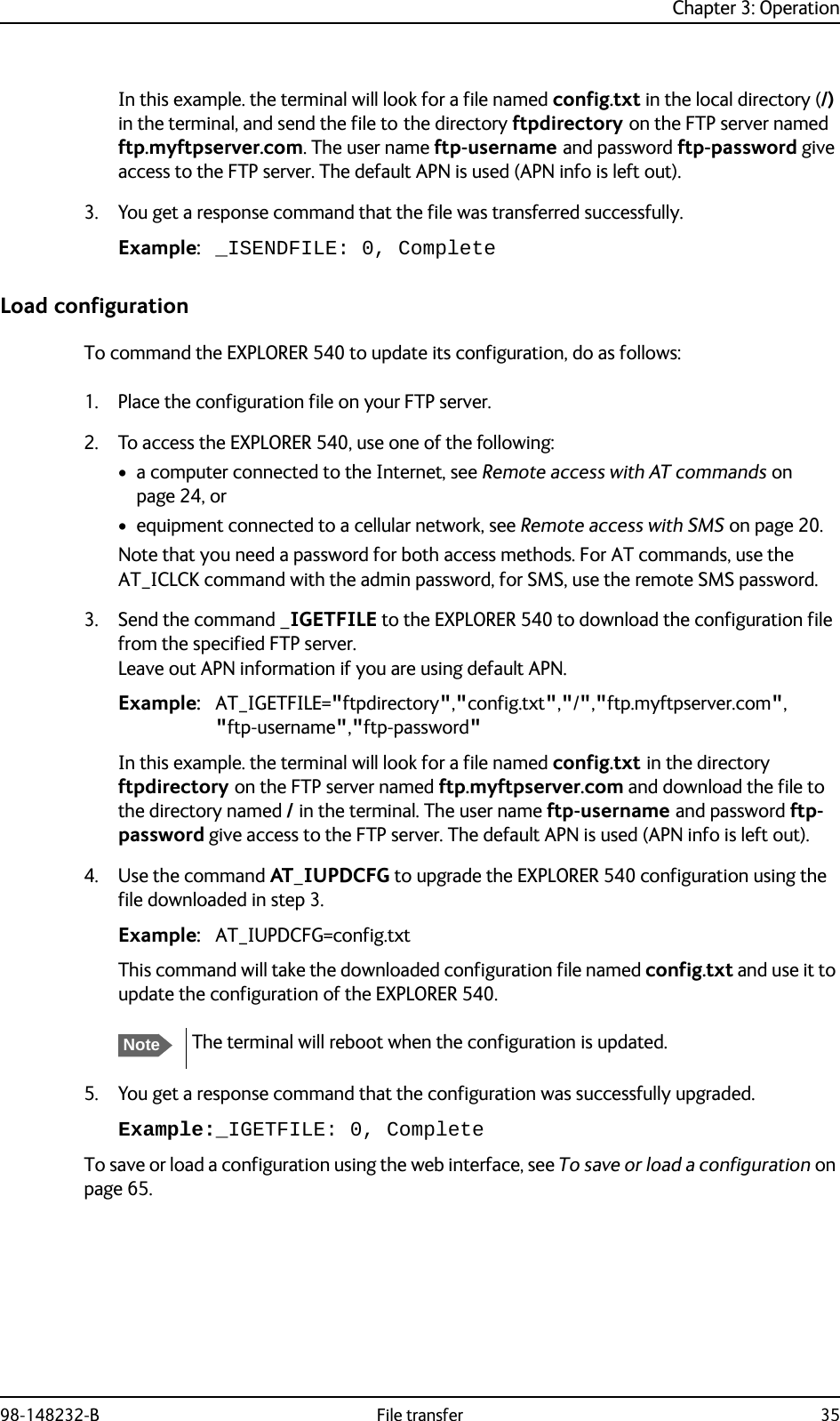
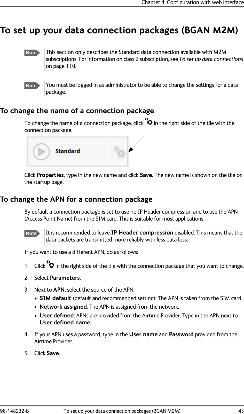
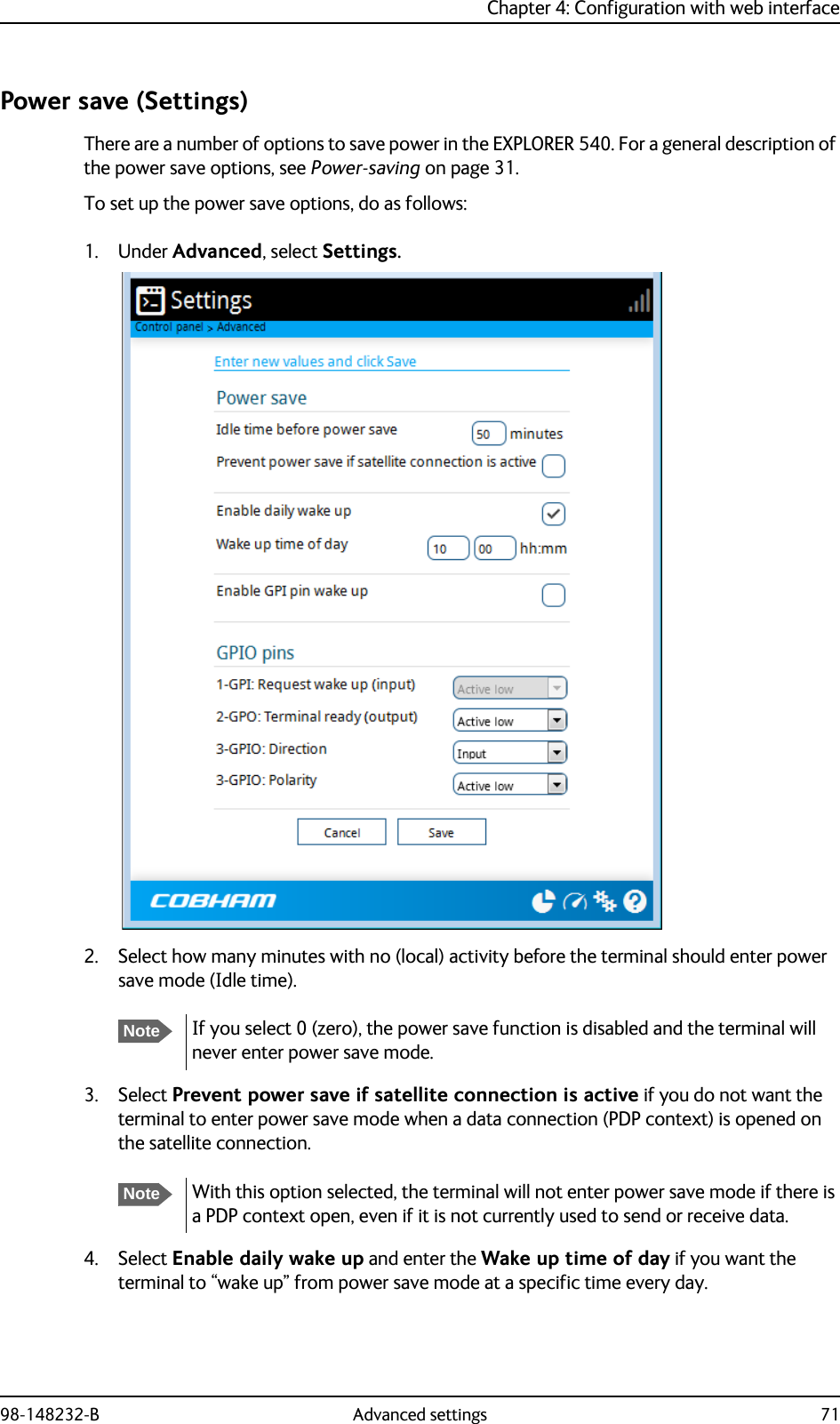
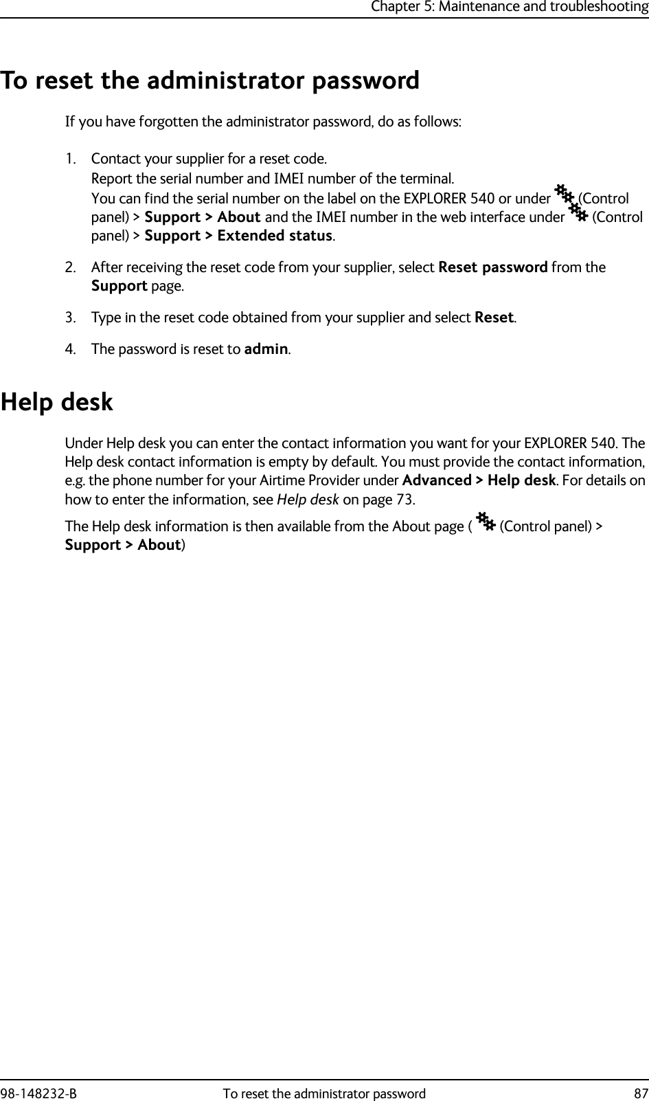
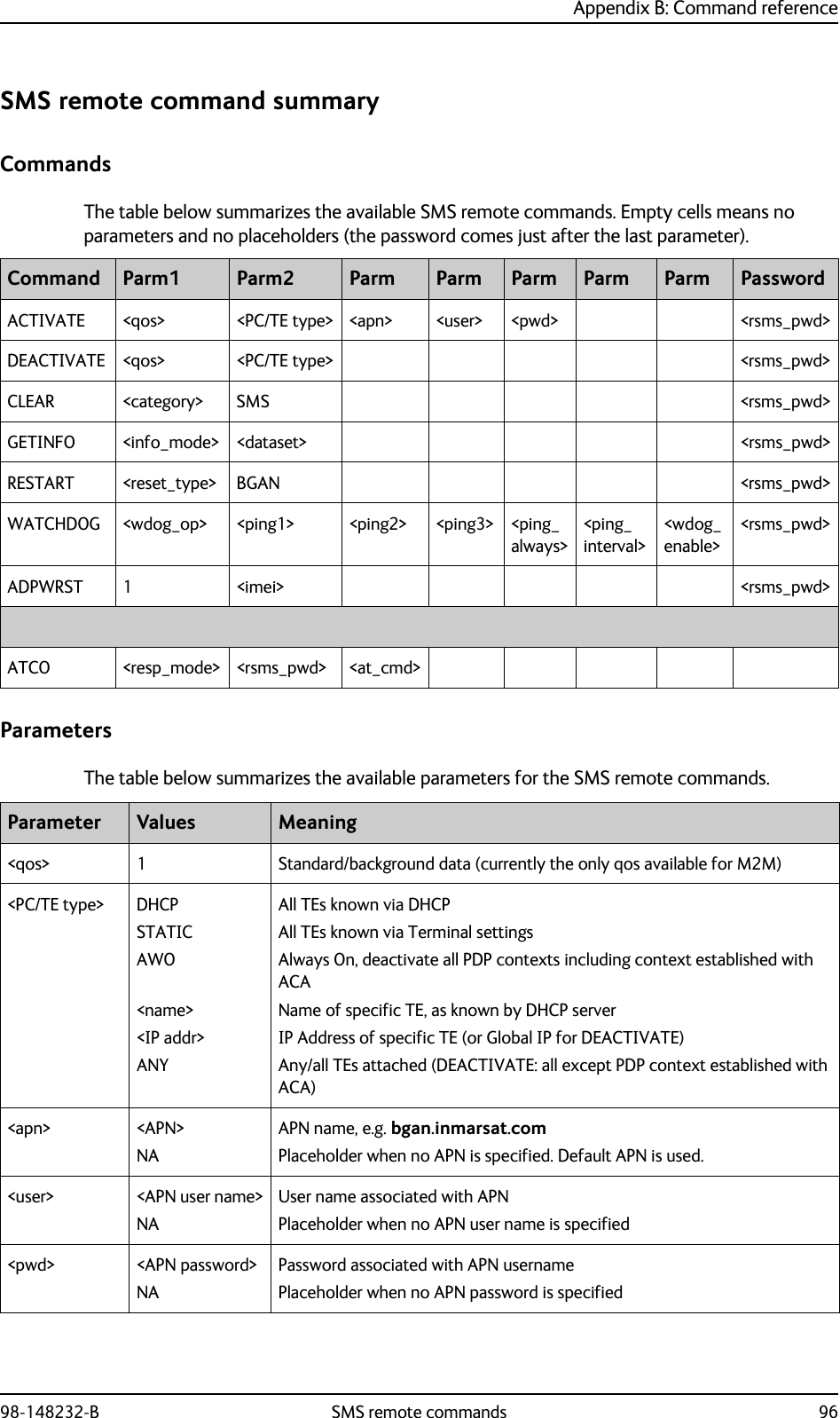
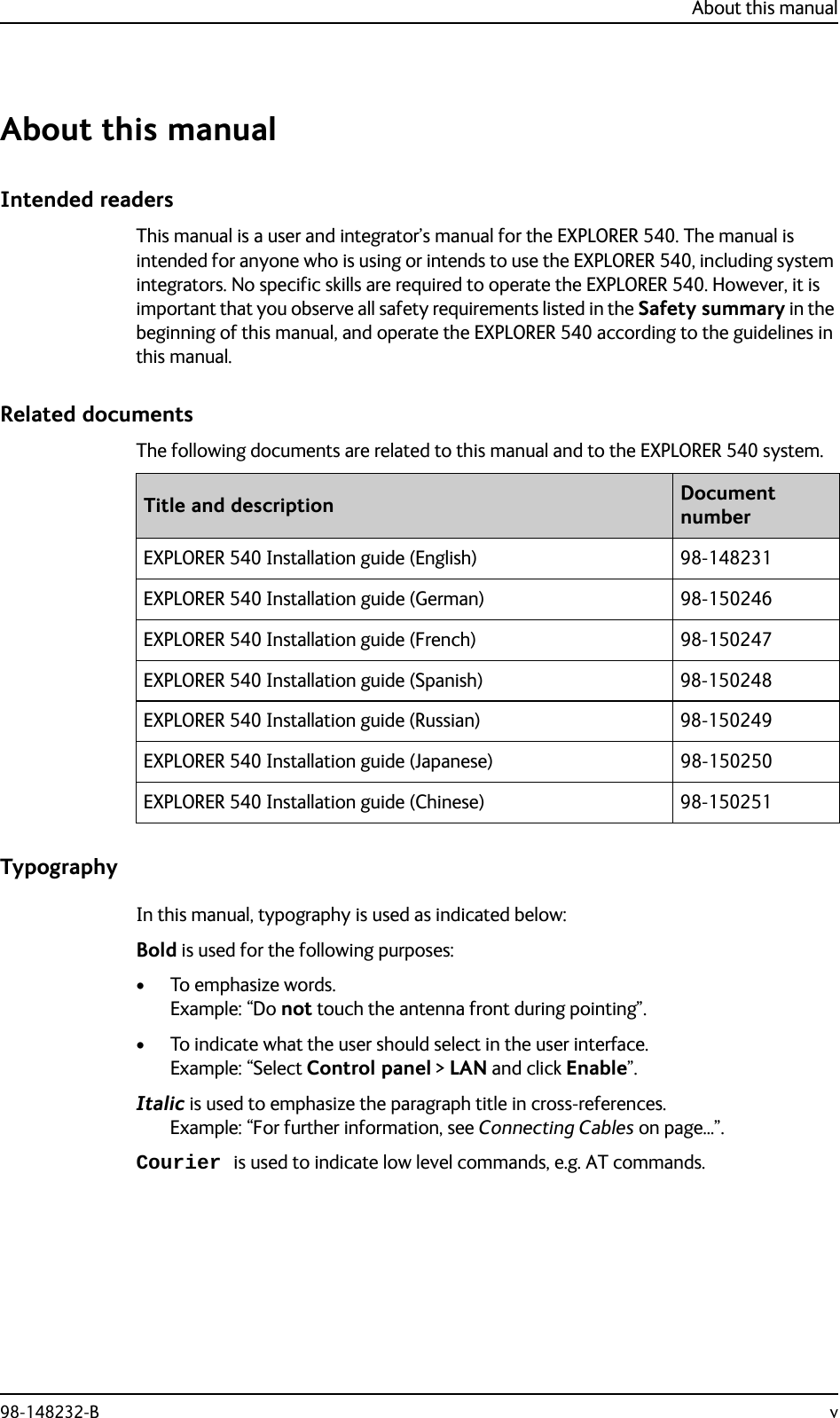
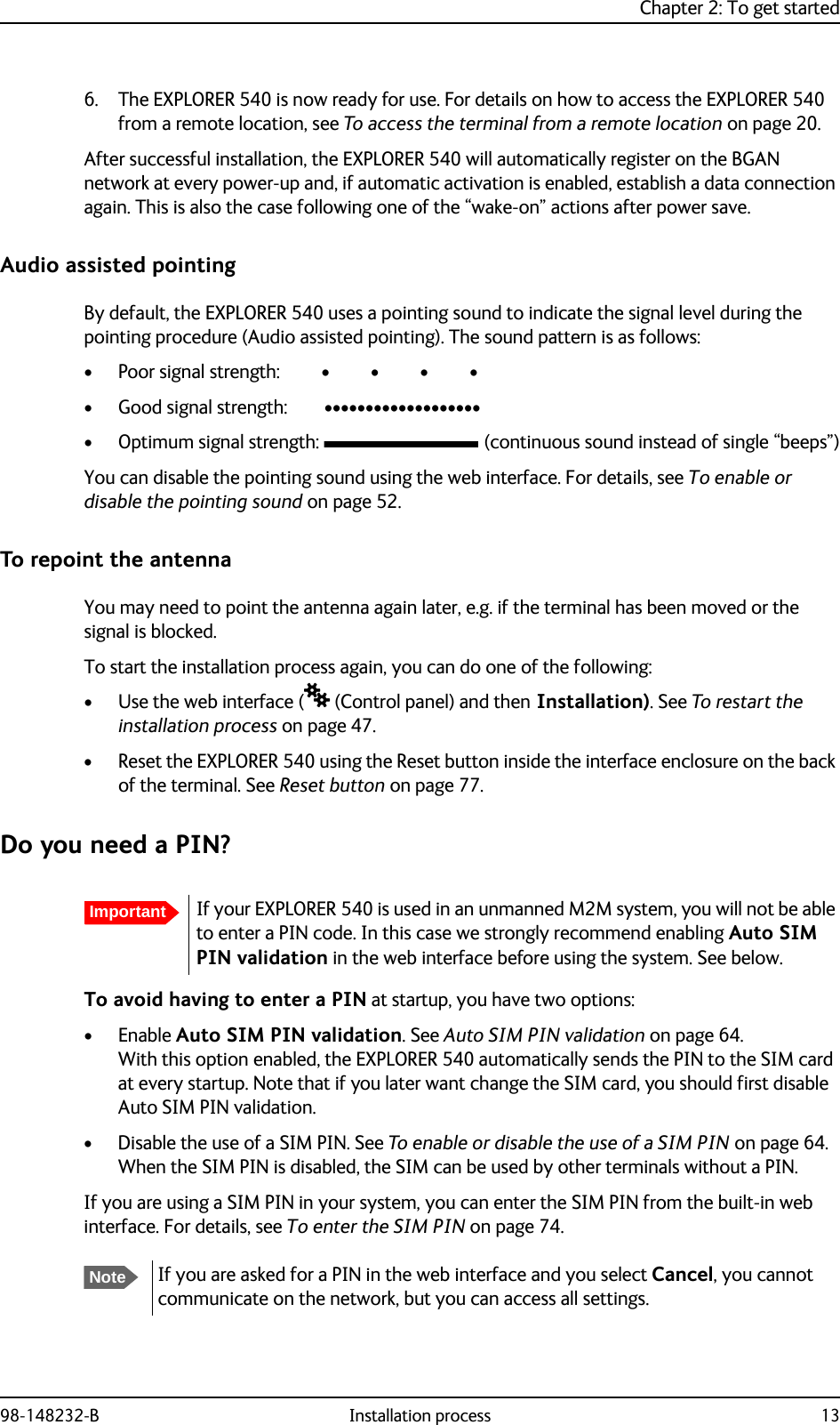
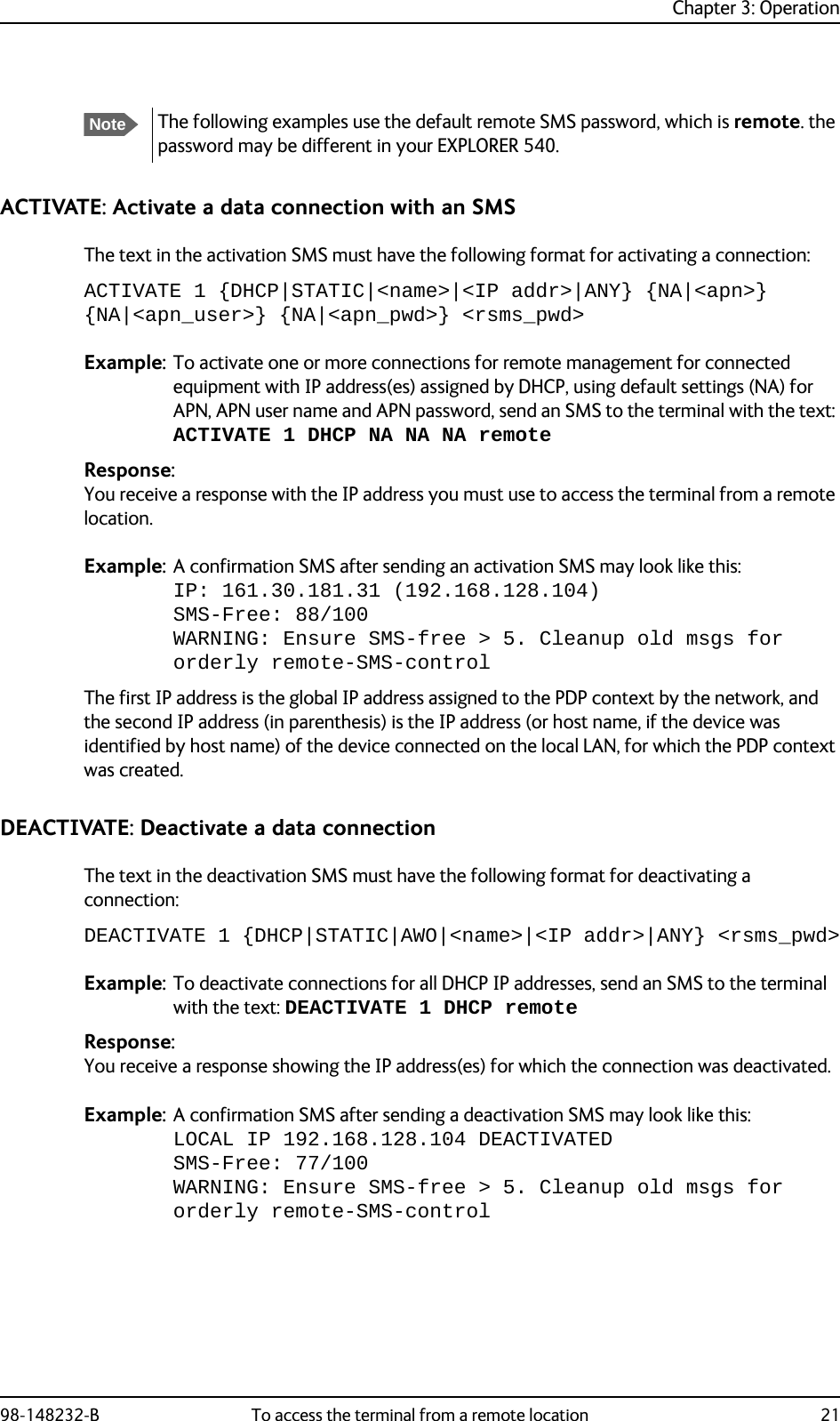
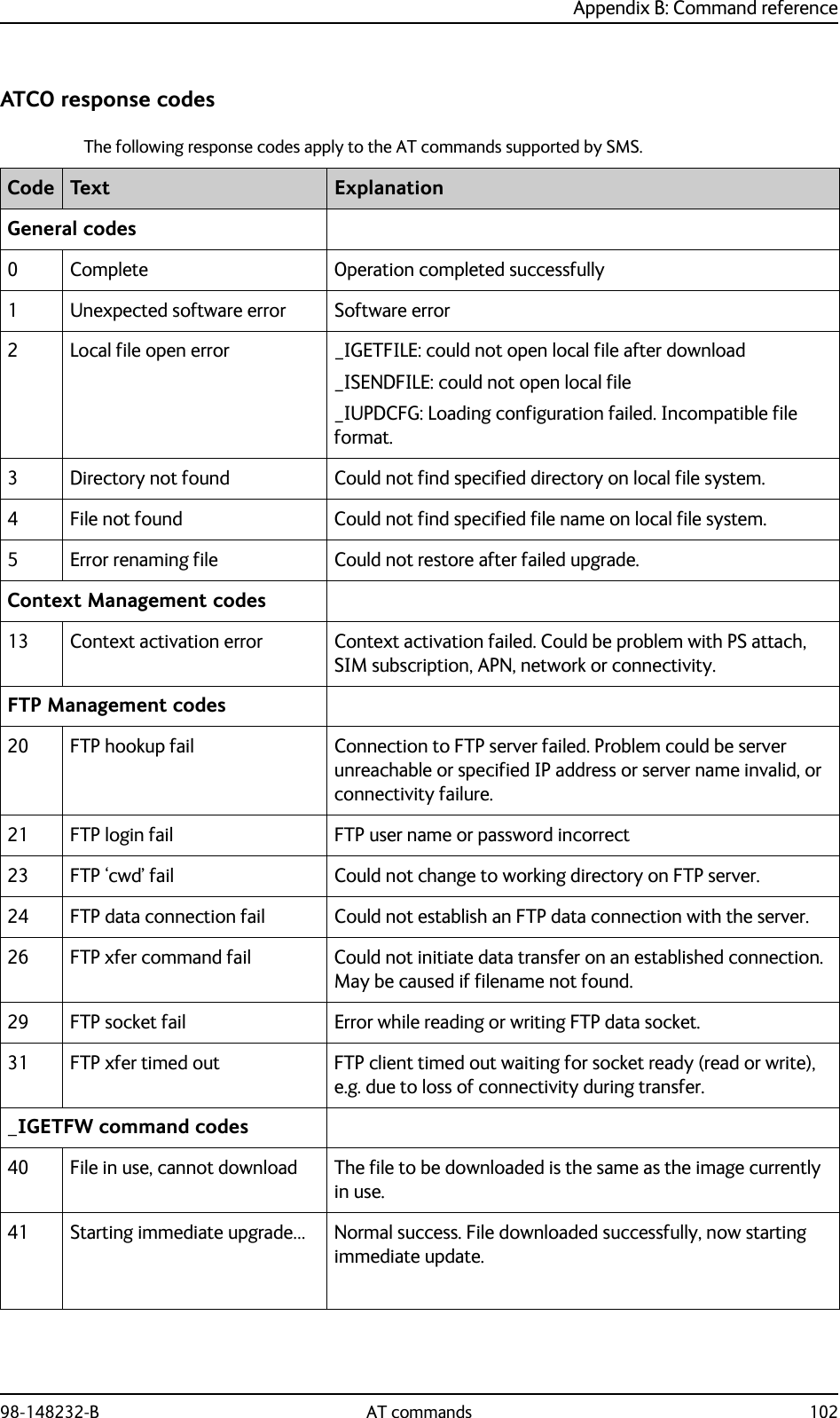
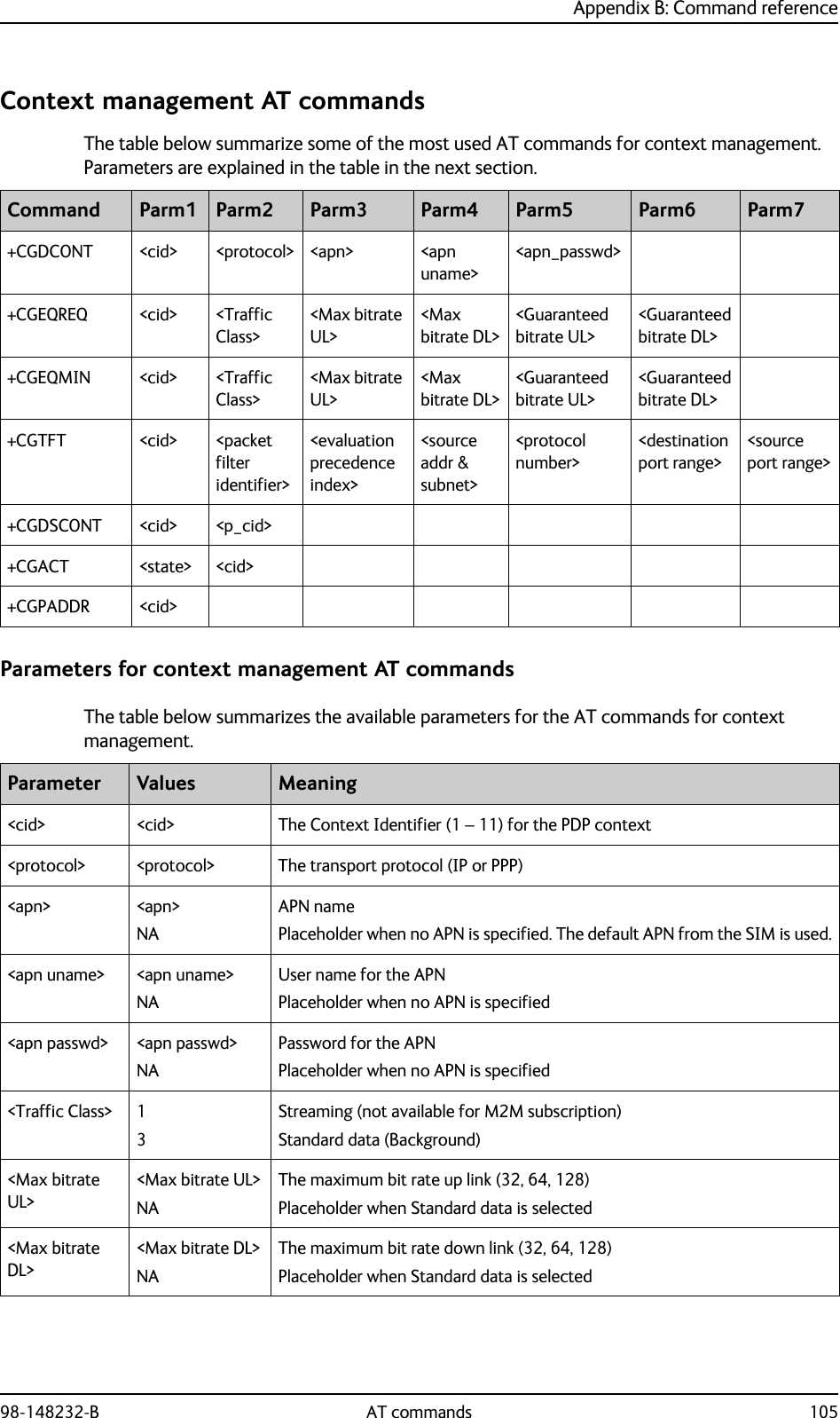
![Appendix B: Command reference98-148232-B SMS remote commands 97<rsms_pwd> <rsms_pwd> Remote SMS password<category> 1234Delete only Read SMS messagesDelete Read and SentDelete All except UnreadDelete All SMS messages<info_mode> 12For GPS query: position data only. For other queries: use verbose mode (with titles)For GPS query: position data plus SMS usage. For other queries: use terse mode (no titles)<dataset> GPSUSAGEALLGPS positionCumulative call time and data usageGPS position plus call time and data usage<reset_type> 1 Normal delay restart<wdog_op> 12Get watchdog configurationSet watchdog parameters<ping[1/2/3]> <IP addr>NAUp to three ping destination IP addressesPlaceholder when no IP address is specified<ping_always> 01NASend ping only if no trafficAlways send ping, regardless of data trafficPlaceholder when no value is specified<ping_interval> <integer>NAInterval between pings (minutes)Placeholder when no value is specified<wdog_enable> 01NADisabledEnabledPlaceholder when no value is specified. The existing setting applies. Used if you want to change one of the other parameters without changing the enabled/disabled setting.<imei> <14 digits> IMEI of the EXPLORER 540, without dashes or check digit<resp_mode> 0123None – send no responses to AT commandsImmediate - immediate responses, but not unsolicitedFinal – suppress immediate if OK, plus unsolicitedAll – send both immediate and unsolicited responses<at_cmd> <at_cmd> AT command, without prefix AT. For supported AT commands, see ATCO commands on page 100.Parameter Values Meaning](https://usermanual.wiki/Thrane-and-Thrane-A-S/3715A/User-Guide-2987760-Page-105.png)
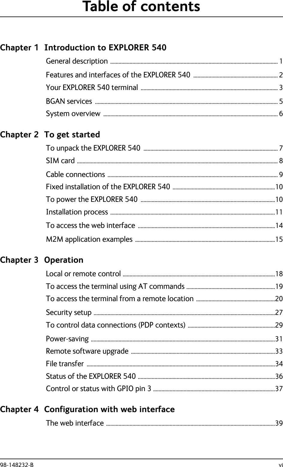
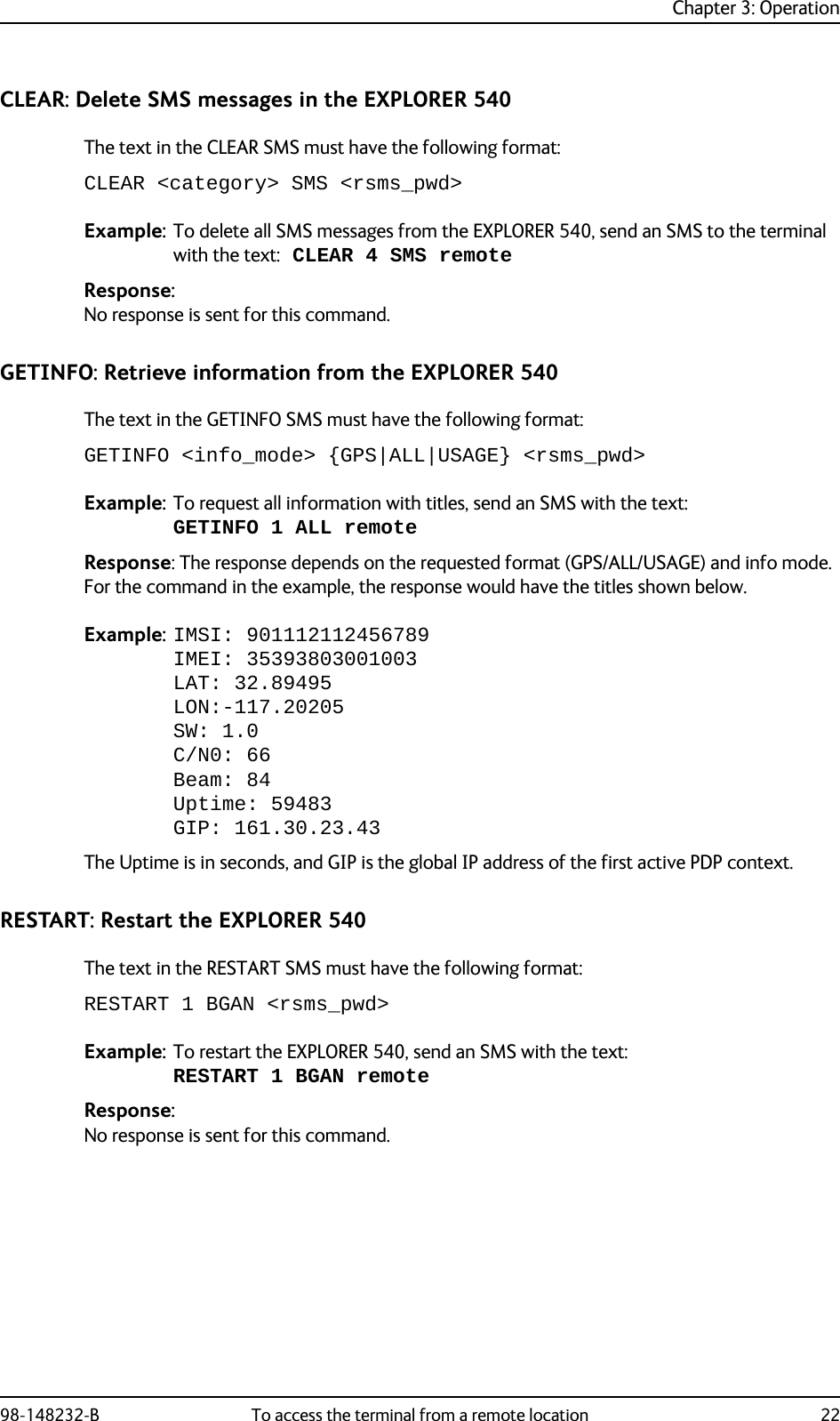
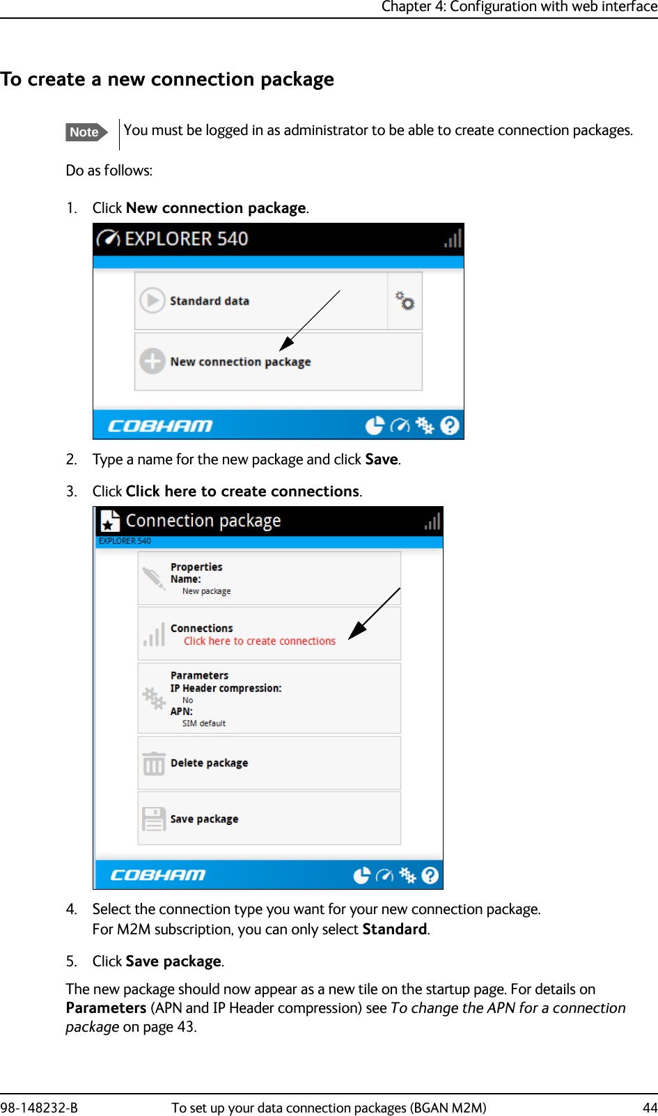
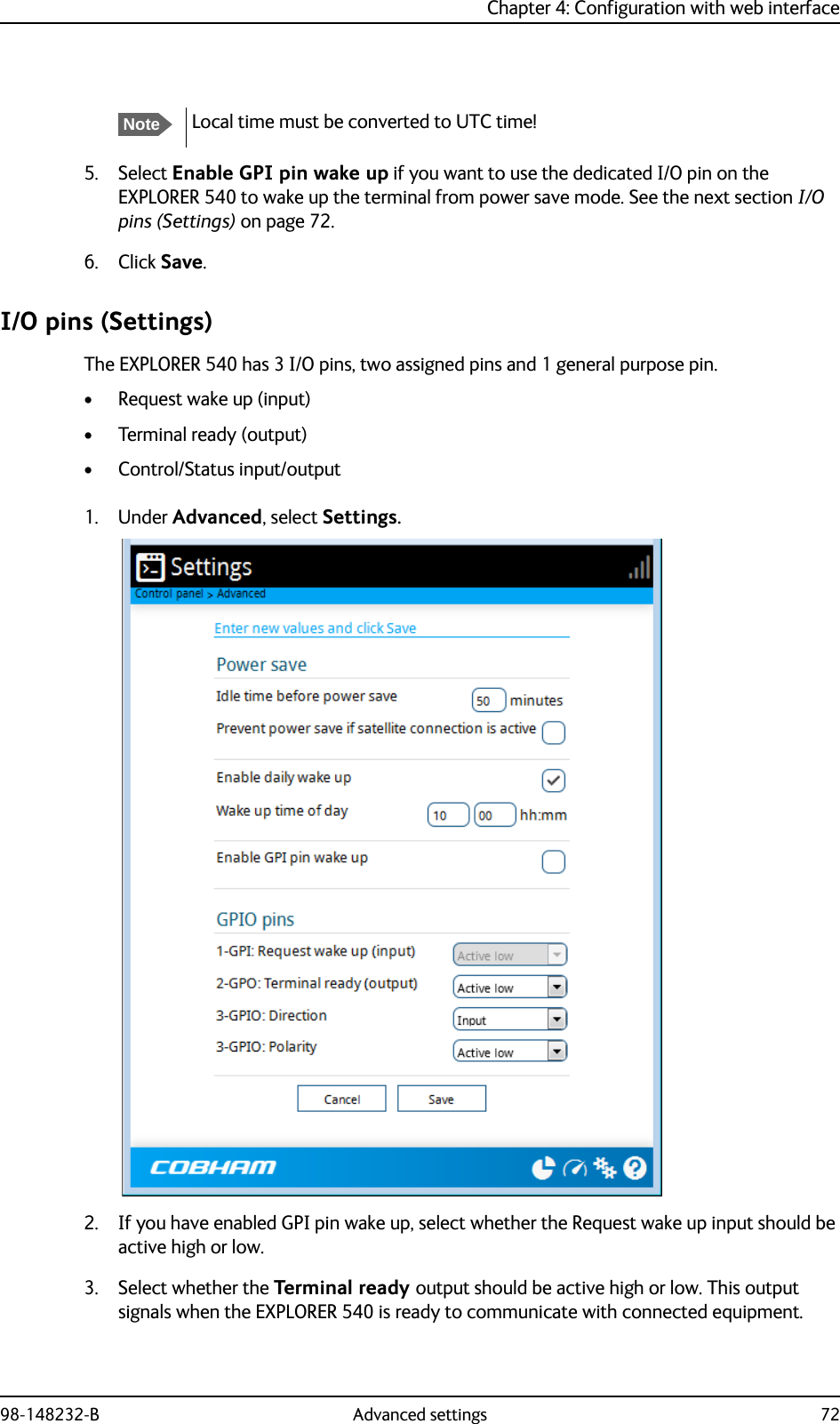
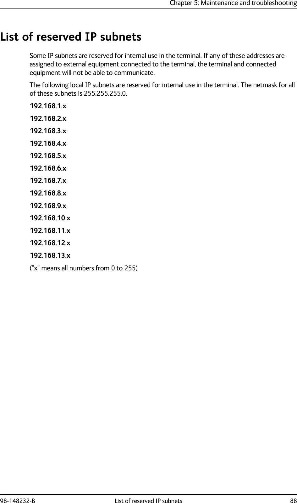
![Appendix B: Command reference98-148232-B AT commands 99AT commandsThe following most used AT commands are explained in this manual. Other AT commands not mentionedhere may still be supported. Syntax conventionsSyntax definitions use the following conventions:• <parm> indicates that a parameter (without < and >) can be filled in by the user.• { <opt1> | <opt2> | … | NA } indicates that one of various options must be chosen by the user. NA means no value is defined. [<options>] indicates that <options> may or may not be included in the command.• String parameters must be enclosed in double-quotes (ASCII 34) and numeric parameters must not be. Only the ASCII double-quote is recognized; slanted quotes, e.g. from the Windows-1252 or UTF-8 character sets, are not valid.• Keywords and parameters are separated by commas.• The command name and all keywords must be in upper case; most user-provided parameters are case sensitive but may be either case.•TE means Terminal Equipment - the equipment connected locally to the EXPLORER 540.](https://usermanual.wiki/Thrane-and-Thrane-A-S/3715A/User-Guide-2987760-Page-107.png)
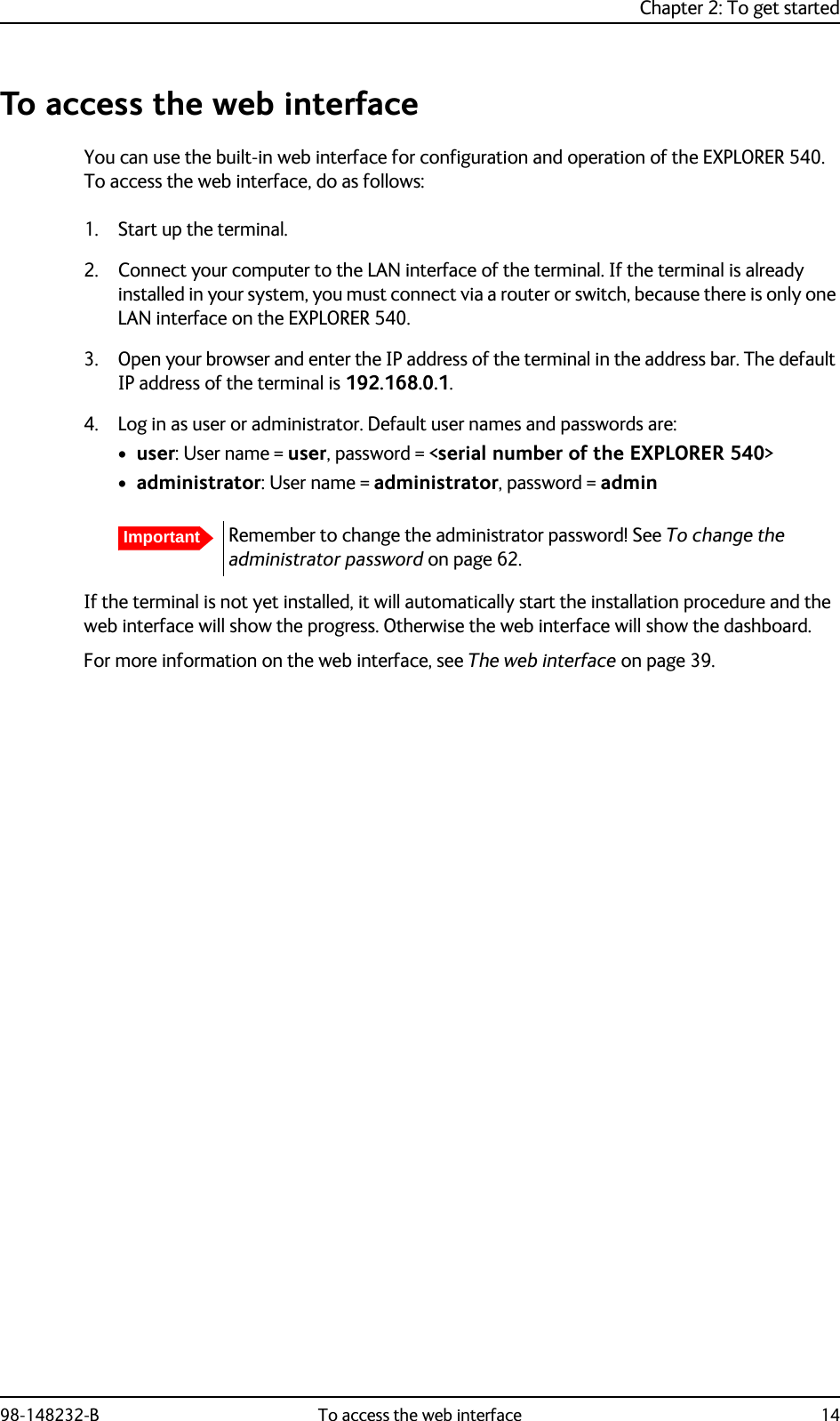
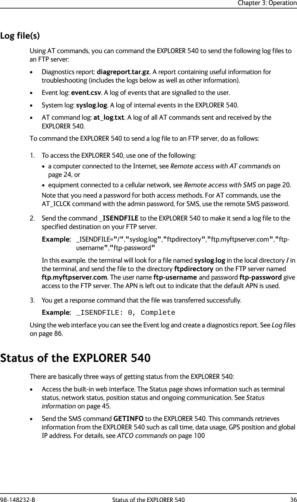
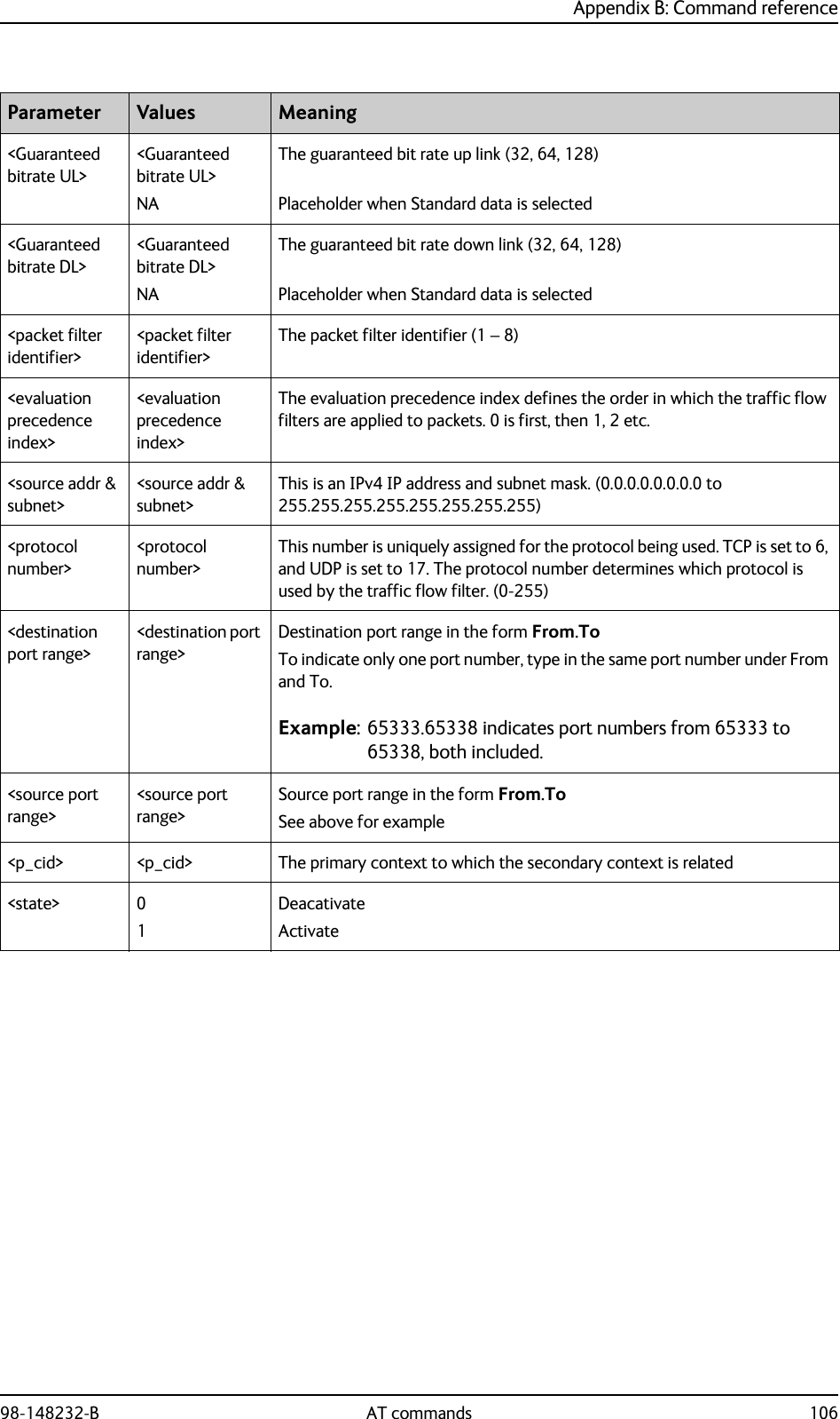
![Appendix B: Command reference98-148232-B AT commands 100M2M related AT commandsThe tables below summarize some of the most used AT commands for M2M operation. Parameters are explained in Parameters for other M2M related AT commands on page 104.ATCO commandsThe table below summarizes the ATCO commands, i.e. AT commands that can be used in the SMS command ATCO.Command Parm1 Parm2 Parm3 Parm4 Parm5 Parm6 Parm7 Parm8 Parm9_IGETFW <mode> [<ftp server>][<ftp uname>][<ftp passwd>][<apn>] [<apn uname>][<apn passwd>]_IUPDFW <filename>_ISENDFILE <local dir> <filename><ftp dir> <ftp server><ftp uname><ftp passwd>[<apn>] [<apn uname>][<apn passwd>]_IGETFILE <ftp dir> <filename><local dir><ftp server><ftp uname><ftp passwd>[<apn>] [<apn uname>][<apn passwd>]_IUPDCFG <filename>_IREMWEB <enable> <ip_addr_lo>[<ip_addr_hi>][<apn>] [<apn uname>][<apn passwd>]_IATCROBSTaa. Robustness for 3GPP LTE signals, not ATC<enable>_ICPWD <type> <old passwd><new passwd>](https://usermanual.wiki/Thrane-and-Thrane-A-S/3715A/User-Guide-2987760-Page-108.png)
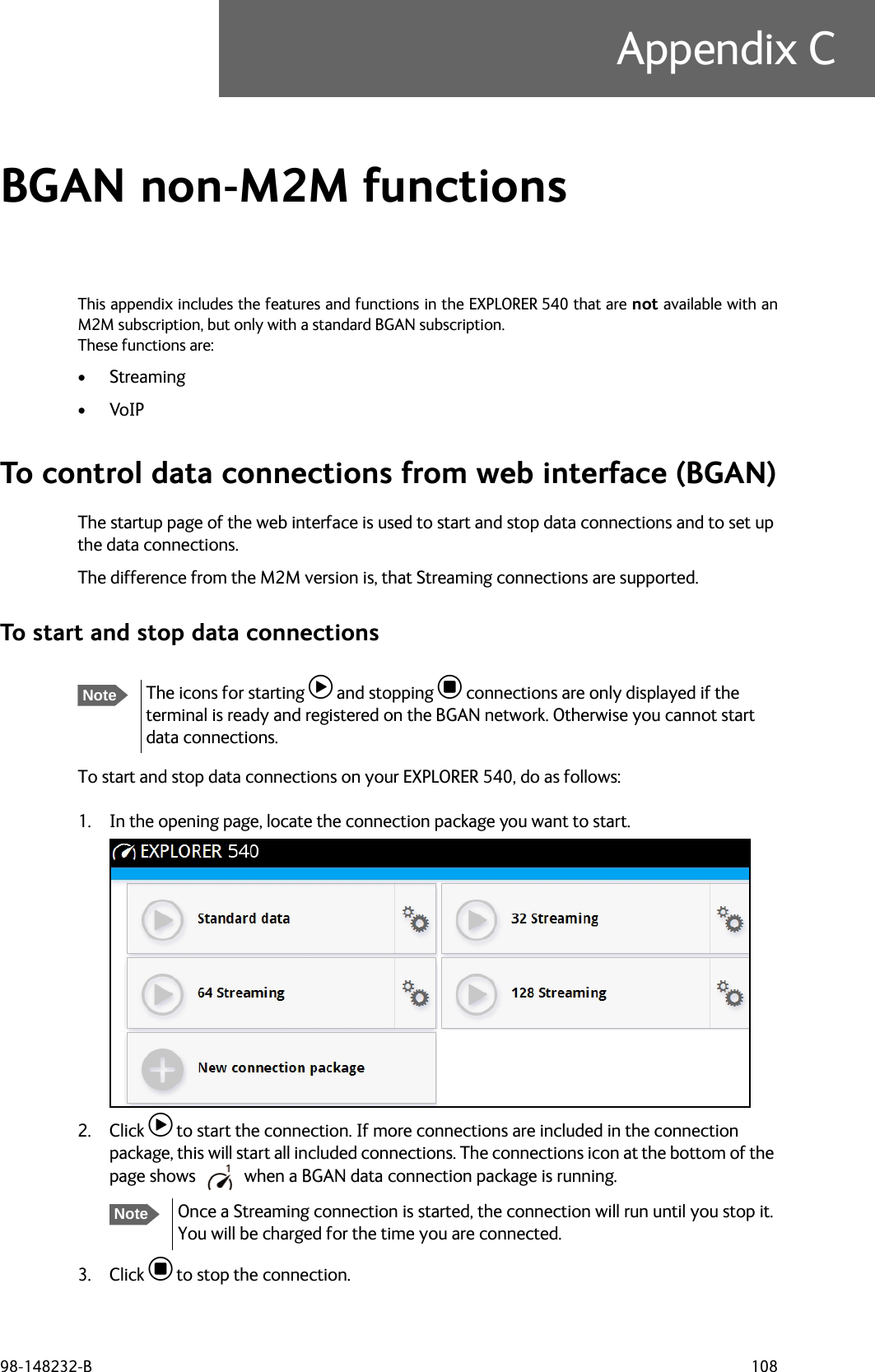
![Appendix B: Command reference98-148232-B AT commands 104Other M2M related AT commandsParameters for other M2M related AT commandsThe table below summarizes the available parameters for the AT commands for M2M operation.Command Parm1 Parm2 Parm3 Parm4_ISMSRMT <enable>_ICLCK <type> <enable> <passwd>_IPWSAVSCHD <psmode> <psvalue>_IMACLOC <enable> <interface> [<interface>]_IMACLOCAD <action> <interface> <MAC Address> [<MAC Address>]aa. Up to 10 MAC addresses may be specified._ITGPIO <active>Parameter Values Meaning<enable> 01DisableEnable<passwd> <passwd> The existing administrator password<psmode> IDLE_TRGTOD_TRGThe power save mode to be set up is “idle trigger”, that is the time with no activity before entering power save modeThe power save mode to be set up is “time of day”, that is a specific time of day where the EXPLORER 540 wakes up from power save mode.<psvalue> <idle-minutes><HH:MM>Used with IDLE_TRG (above). Number of minutes (e.g. 15)Used with TOD_TRG (above). Time of day (e.g. 23:30)<interface> 0 0 means Ethernet interface. This is the only option.<action> 01DeleteAdd<MAC Address><MAC Address> MAC address(es) for MAC locking. Up to 10 MAC addresses are permitted.<active> 01Inactive. The GPIO pin is in its inactive state.Active. The GPIO pin is in its active state.](https://usermanual.wiki/Thrane-and-Thrane-A-S/3715A/User-Guide-2987760-Page-112.png)
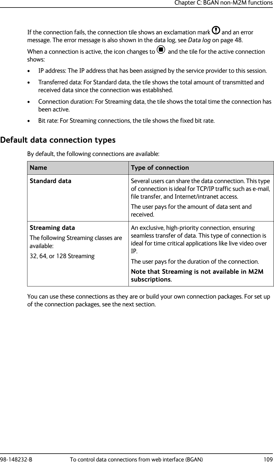
![Appendix B: Command reference98-148232-B AT commands 107Message (SMS) configuration AT commandsThe following AT commands are used for configuration of SMS.NoteFor details on parameters for the message configuration commands, see the 3GPP standard ETSI TS 127 005 V4.2.1.Command Parm1 Parm2 Parm3 Parm4 Function+CSMS <service> Select Message Service+CPMS <mem1> [<mem2> [<mem3>]]Preferred Message Storage+CMGF <mode> Message Format+CSCA <sca> [<tosca>] Service Center Address+CSMP [<fo> [<vp> [<pid> [<dcs>]]]]Set Text Mode Parameters+CSDH <show> Show Text Mode Parameters+CNMI [<mode> [<mt> [<bm> [<ds>]]]] New Message Indications to TE+CMGL <stat> List Messages+CMGR <index> Read Messages+CMGS <da/mr> [<toda/scts>]Send Message+CMGD <index> Delete Message](https://usermanual.wiki/Thrane-and-Thrane-A-S/3715A/User-Guide-2987760-Page-115.png)
![98-148232-B 115Appendix DConformity DCE (R&TTE)The EXPLORER 540 is CE certified (R&TTE directive) as stated in “Declaration of Conformity with R&TTE Directive” enclosed in electronic copy at the end of this appendix.ICThis device complies with Industry Canada licence-exempt RSS standard(s). Operation is subject to the following two conditions: (1) this device may not cause interference, and (2) this device must accept any interference, including interference that may cause undesired operation of the device.Le présent appareil est conforme aux CNR d'Industrie Canada applicables aux appareils radio exempts de licence. L'exploitation est autorisée aux deux conditions suivantes : (1) l'appareil ne doit pas produire de brouillage, et (2) l'utilisateur de l'appareil doit accepter tout brouillage radioélectrique subi, même si le brouillage est susceptible d'en compromettre le fonctionnement.This Class [B] digital apparatus complies with Canadian ICES-003.Cet appareil numérique de la classe [B] est conforme à la norme NMB-003 du Canada.FCCNote: This equipment has been tested and found to comply with the limits for a Class B digital device, pursuant to part 15 of the FCC Rules. These limits are designed to provide reasonable protection against harmful interference in a residential installation. This equipment generates, uses and can radiate radio frequency energy and, if not installed and used in accordance with the instructions, may cause harmful interference to radio communications. However, there is no guarantee that interference will not occur in a particular installation. If this equipment does cause harmful interference to radio or television reception, which can be determined by turning the equipment off and on, the user is encouraged to try to correct the interference by one or more of the following measures:• Reorient or relocate the receiving antenna• Increase the separation between the equipment and receiver• Connect the equipment into an outlet on a circuit different from that to which the receiver is connected• Consult the dealer or an experienced radio/TV technician for help](https://usermanual.wiki/Thrane-and-Thrane-A-S/3715A/User-Guide-2987760-Page-123.png)