Thrane and Thrane A S 3715A TT-3715A User Manual E540
Thrane & Thrane A/S TT-3715A E540
UseerManual.pdf
EXPLORER 540
User & integrator’s manual
98-148232-B ii
Document number: 98-148232-B
Release date: 26 April 2016
Disclaimer
Any responsibility or liability for loss or damage in connection with the use of this product and the
accompanying documentation is disclaimed by Thrane & Thrane A/S. The information in this manual is
provided for information purposes only, is subject to change without notice and may contain errors or
inaccuracies. Manuals issued by Thrane & Thrane A/S are periodically revised and updated. Anyone
relying on this information should acquire the most current version e.g. from www.cobham.com/satcom,
Service and support, or from the distributor. Thrane & Thrane A/S is not responsible for the content or
accuracy of any translations or reproductions, in whole or in part, of this manual from any other source.
In the event of any discrepancies, the English version shall be the governing text.
Thrane & Thrane A/S is trading as Cobham SATCOM.
Copyright
© 2016 Thrane & Thrane A/S. All rights reserved.
Trademark acknowledgements
•Inmarsat is a registered trademark of the International Maritime Satellite Organisation (IMSO) and
is licensed by IMSO to Inmarsat Limited and Inmarsat Ventures plc.
• Other product and company names mentioned in this manual may be trademarks or trade names of
their respective owners.

98-148232-B iii
Safety summary 1
The following general safety precautions must be observed during all phases of operation, service
and repair of this equipment. Failure to comply with these precautions or with specific warnings
elsewhere in this manual violates safety standards of design, manufacture and intended use of the
equipment. Thrane & Thrane A/S assumes no liability for the customer's failure to comply with
these requirements.
If the equipment is used in a manner not specified by the manufacturer, the protection may be
impaired.
Keep away from live circuits
Operating personnel must not remove equipment covers, other than the cover for the interface
enclosure. Component replacement and internal adjustment must be made by qualified
maintenance personnel. Do not replace components with the power cable connected. Under
certain conditions, dangerous voltages may exist even with the power cable removed. To avoid
injuries, always disconnect power and discharge circuits before touching them.
Do not substitute parts or modify equipment
Because of the danger of introducing additional hazards, do not substitute parts or perform any
unauthorized modification to the equipment.
Keep away from antenna front
This device emits radio frequency energy when switched on. To avoid
injury, keep a minimum safety distance of 1 m from the antenna front
when the EXPLORER 540 is on.
Garder à l'écart de l'avant de l'antenne
Le présent appareil émet des radiofréquences lors de son utilisation. Afin
d'éviter tout risque pour la santé, une distance minimale de 1 m est nécessaire entre l'utilisateur et
l'avant de l'EXPLORER 540.
Observe marked areas
Under extreme heat conditions do not touch areas of the EXPLORER 540
that are marked with this symbol, as it may result in injury.
Antenna safety instructions
98-148232-B iv
Antenna safety instructions 2
Use only manufacturer supplied antennas.
Antenna minimum safe distance: 1 m
Antenna gain
Directional, with maximum gain of 11.25 dBi (with reference to isotropic).
The Federal Communications Commission has adopted a safety standard for human
exposure to RF (Radio Frequency) energy which is below the OSHA (Occupational Safety
and Health Act) limits.
Antenna mounting
The antenna supplied by the manufacturer must be located such that during radio
transmission, no person or persons can come closer than the above indicated minimum
safe distance to the front face of the antenna, i.e. 1 m.
L'antenne fournie par le fabricant doit être placée de telle sorte que, durant les
transmissions radio, personne ni aucun groupe de personnes ne puisse s'approcher à une
distance inférieur à la distance de sécurité minimal indiquée ci-dessus, c.-à-d., 1 m.
To comply with current FCC RF Exposure limits, the antenna must be installed at or
exceeding the minimum safe distance shown above, and in accordance with the
requirements of the antenna manufacturer or supplier.
Radiation warning
You, as the qualified end-user of this radio device, must control the exposure conditions
of bystanders to ensure the minimum separation distance (above) is maintained
between the antenna and nearby persons, for satisfying RF Exposure compliance. The
operation of this transmitter must satisfy the requirements of General Population/
Uncontrolled Environment. Only use the terminal when persons are at least the
minimum distance from the front face of the antenna.
WARNING! Maintain a separation distance of at least 1 m from the front
face of the antenna to a person.

About this manual
98-148232-B v
About this manual 3
Intended readers
This manual is a user and integrator’s manual for the EXPLORER 540. The manual is
intended for anyone who is using or intends to use the EXPLORER 540, including system
integrators. No specific skills are required to operate the EXPLORER 540. However, it is
important that you observe all safety requirements listed in the Safety summary in the
beginning of this manual, and operate the EXPLORER 540 according to the guidelines in
this manual.
Related documents
The following documents are related to this manual and to the EXPLORER 540 system.
Typography
In this manual, typography is used as indicated below:
Bold is used for the following purposes:
•To emphasize words.
Example: “Do not touch the antenna front during pointing”.
• To indicate what the user should select in the user interface.
Example: “Select Control panel > LAN and click Enable”.
Italic is used to emphasize the paragraph title in cross-references.
Example: “For further information, see Connecting Cables on page...”.
Courier is used to indicate low level commands, e.g. AT commands.
Title and description Document
number
EXPLORER 540 Installation guide (English) 98-148231
EXPLORER 540 Installation guide (German) 98-150246
EXPLORER 540 Installation guide (French) 98-150247
EXPLORER 540 Installation guide (Spanish) 98-150248
EXPLORER 540 Installation guide (Russian) 98-150249
EXPLORER 540 Installation guide (Japanese) 98-150250
EXPLORER 540 Installation guide (Chinese) 98-150251

98-148232-B vi
Table of contents
Chapter 1 Introduction to EXPLORER 540
General description ......................................................................................................................... 1
Features and interfaces of the EXPLORER 540 ............................................................. 2
Your EXPLORER 540 terminal ................................................................................................... 3
BGAN services .................................................................................................................................... 5
System overview .............................................................................................................................. 6
Chapter 2 To get started
To unpack the EXPLORER 540 ................................................................................................. 7
SIM card ................................................................................................................................................. 8
Cable connections ........................................................................................................................... 9
Fixed installation of the EXPLORER 540 ..........................................................................10
To power the EXPLORER 540 .................................................................................................10
Installation process .......................................................................................................................11
To access the web interface ...................................................................................................14
M2M application examples .....................................................................................................15
Chapter 3 Operation
Local or remote control ..............................................................................................................18
To access the terminal using AT commands ................................................................19
To access the terminal from a remote location .........................................................20
Security setup ...................................................................................................................................27
To control data connections (PDP contexts) ...............................................................29
Power-saving .....................................................................................................................................31
Remote software upgrade ........................................................................................................33
File transfer ........................................................................................................................................34
Status of the EXPLORER 540 ...................................................................................................36
Control or status with GPIO pin 3 ........................................................................................37
Chapter 4 Configuration with web interface
The web interface ..........................................................................................................................39

Table of contents
98-148232-B vii
To control data connections from web interface .....................................................42
To set up your data connection packages (BGAN M2M) .....................................43
Status information .........................................................................................................................45
The Control panel ..........................................................................................................................46
To restart the installation process .......................................................................................47
To use the logs .................................................................................................................................48
Terminal settings ............................................................................................................................49
Port forwarding ................................................................................................................................53
To manage connected devices (Traffic control) .......................................................54
To set up tracking ..........................................................................................................................57
Support features .............................................................................................................................59
Advanced settings .........................................................................................................................62
To enter the SIM PIN in the web interface ...................................................................74
Chapter 5 Maintenance and troubleshooting
Support .................................................................................................................................................75
Software update .............................................................................................................................76
Reset button ......................................................................................................................................77
Maintenance .....................................................................................................................................78
Troubleshooting ..............................................................................................................................78
Log files .................................................................................................................................................86
To view extended status ...........................................................................................................86
To reset the administrator password .................................................................................87
Help desk ..............................................................................................................................................87
List of reserved IP subnets .......................................................................................................88
App. A Technical specifications
General specifications .................................................................................................................89
Interfaces specifications ...........................................................................................................90
Built-in BGAN antenna ................................................................................................................92
Outline drawing ...............................................................................................................................93

Table of contents
98-148232-B viii
App. B Command reference
SMS remote commands ............................................................................................................95
AT commands ..................................................................................................................................99
App. C BGAN non-M2M functions
To control data connections from web interface (BGAN) ...............................108
To set up data connections ..................................................................................................110
To make phone calls over BGAN (not M2M version) ..........................................111
To manage VoIP phones or smartphones ...................................................................114
App. D Conformity
CE (R&TTE) ......................................................................................................................................115
IC ...........................................................................................................................................................115
FCC .......................................................................................................................................................115
Japanese Radio Law and Japanese Telecommunications Business Law
Compliance. ....................................................................................................................................116
Glossary ...................................................................................................................................................................118
Index ...................................................................................................................................................................121
98-148232-B General description 1
Chapter 1
Introduction to EXPLORER 540 1
General description
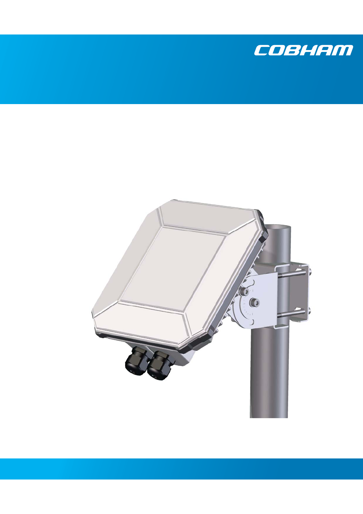
The EXPLORER 540 is a small and light BGAN M2M terminal. The durable casing and a dust and
water resistant design makes the EXPLORER 540 the perfect choice for any kind of fixed
outside installation.
Depending on your airtime subscription, the EXPLORER 540 either operates as an M2M
(machine-to-machine) terminal or as a standard class 2 terminal.

Chapter 1: Introduction to EXPLORER 540
98-148232-B Features and interfaces of the EXPLORER 540 2
Features and interfaces of the EXPLORER 540
Features
M2M or standard class 2, depending on airtime subscription (SIM card)
Automatic installation function
Standard data up to 464/448 kbps (download/upload)
Remote management
SMS for remote management
Power save functions with various “wake on” methods (timer or input pin)
Software upgrade and file transfer over-the-air
Connectivity “watchdog” function (Link monitoring)
Automatic context activation
For the M2M version only:
• Inmarsat M2M Access Platform
• Access to Inmarsat FTP server for firmware upgrade
For the non-M2M version: only
• Streaming data rates of 32, 64 and 128 kbps
• Voice over IP (Standard voice 4 kbps AMBE+2 codec or Premium voice 3.1 kHz audio 64
kbps)
IP66 protection
Built-in web interface allowing you to manage connections and customize the terminal to
your specific needs, using a computer
Support for GPS, GLONASS and BeiDou navigation systems
Interfaces
LAN interface with Power over Ethernet (PoE) input
I/O ports for control of power save mode and for remote control/status
Power input from:
• PoE+ (IEEE 802.3at type 2 class 4, 25 W) or
• separate DC power source, e.g. a battery (max. range 10.5-32 VDC)
Chapter 1: Introduction to EXPLORER 540
98-148232-B Your EXPLORER 540 terminal 3
Approvals/certificates
Your EXPLORER 540 terminal
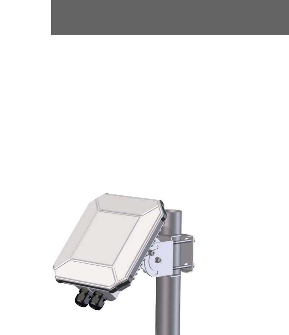
EXPLORER 540 overview
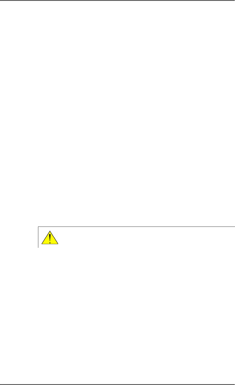
The EXPLORER 540 is a small, compact unit comprising transceiver and antenna in one unit.
Country Approval / certificate
EU CE
US FCC
Canada IC
Australia / New Zealand RCM
Russia Type approval certificate in the
field of communications
Japan Radio Law
International GMPCS
International C1D2
International Inmarsat Class 2 Type Approved
and BGAN M2M Certified
Antenna for
BGAN and GNSS
LAN
BGAN SIM card
Status LED
DC power
Cable glands for:

Chapter 1: Introduction to EXPLORER 540
98-148232-B Your EXPLORER 540 terminal 4
User interfaces
The web interface is a built-in web interface for easy configuration. The web interface is
accessed from a computer connected to the EXPLORER 540, using an Internet browser. No
installation of software is needed on the computer. For further information on the web
interface, see The web interface on page 39.
With AT commands you can configure and control the EXPLORER 540 from a computer
using a Telnet session, or from connected equipment, e.g. in M2M applications. For further
details see To access the terminal using AT commands on page 19.
With SMS commands you can configure and control the EXPLORER 540 remotely. For
details, see Remote access with SMS on page 20.
The distributors may have their own Graphical User Interface, which could be built on e.g.
Inmarsat's M2M API (M2MAP) or similar. Contact your distributor for information.
Antenna
The plastic part of the EXPLORER 540 holds the antenna part comprising:
• GNSS (Global Navigation Satellite System) antenna supporting GPS, GLONASS and BeiDou.
• BGAN antenna.
SIM card
The EXPLORER 540 requires a SIM card to go online with BGAN. Without a SIM card you can
still configure the terminal, but you cannot make calls nor access the internet.
Your SIM card determines whether your EXPLORER 540 is operating as an M2M terminal or as
a standard class 2 terminal.
SIM lock: The supplier may have locked the SIM card to a specific provider. For further
information, contact your supplier.
Chapter 1: Introduction to EXPLORER 540
98-148232-B BGAN services 5
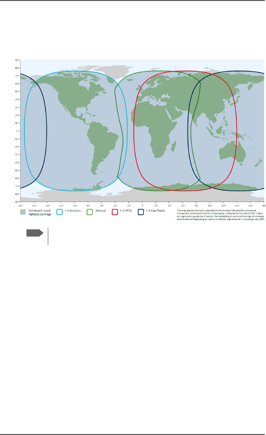
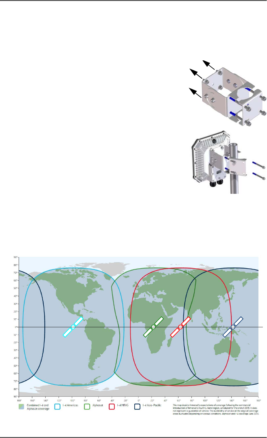
BGAN services
The Inmarsat BGAN services are based on the BGAN I4 geostationary satellites and the
Alphasat satellite. The map below shows the coverage area.
BGAN M2M services
BGAN M2M gives you a data connection to remote equipment and applications. With a BGAN
M2M SIM card you have the following data capability:
• Standard data (background and interactive) up to 464 kbps/448 kbps.
• SMS for remote management.
Not supported: Streaming and voice calls.
Standard class 2 services
With a standard Class 2 SIM card you have the following data capabilities:
• Standard data (background and interactive) up to 464 kbps/448 kbps.
• Streaming data rates of 32, 64 and 128 kbps.
Via the EXPLORER 540 LAN interface, a SIP client (in a phone or M2M equipment) has the
following voice capabilities:
• Standard voice 4 kbps AMBE+2 codec
Note
The services available depend on the SIM card installed in the EXPLORER 540. You can
have A BGAN M2M subscription or a standard class 2 subscription.
Chapter 1: Introduction to EXPLORER 540
98-148232-B System overview 6
• Premium voice 3.1 kHz audio 64 kbps
Additionally:
• SMS for remote management
For details about non-M2M functions, see BGAN non-M2M functions on page 108.
System overview
Power supply and additional equipment
There is one LAN interface and one DC power input on the EXPLORER 540.
Depending on your configuration, you may have to use a PoE switch or a PoE injector
connected to the LAN interface or a battery connected to the DC input in order to provide
power to the EXPLORER 540. For examples, see M2M application examples on page 15. You
may also need to provide a switch to be able to accommodate more than one LAN connection,
e.g. for local access to the web interface during installation or service.
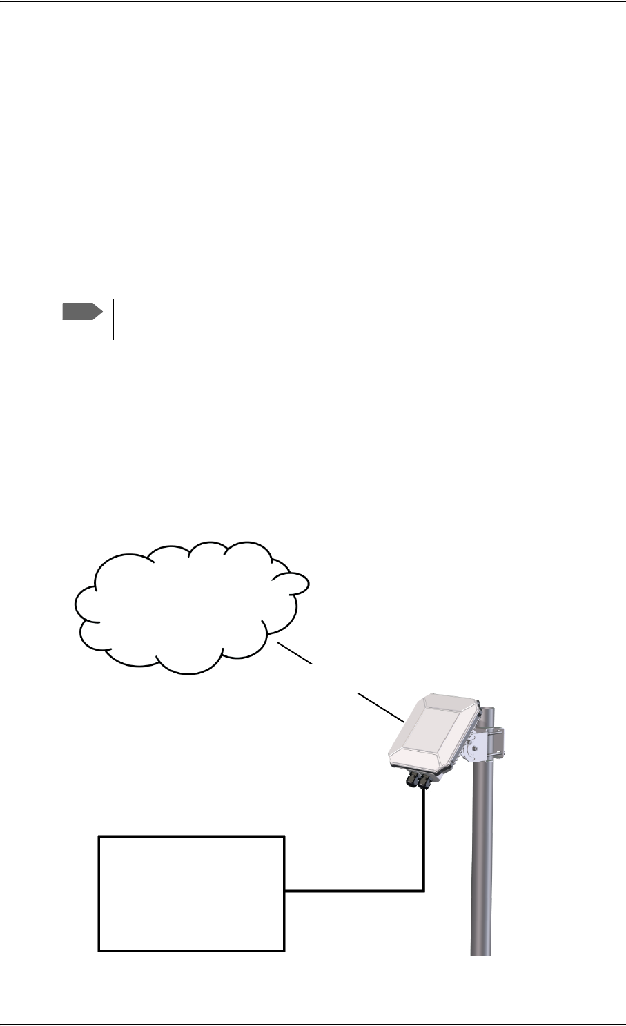
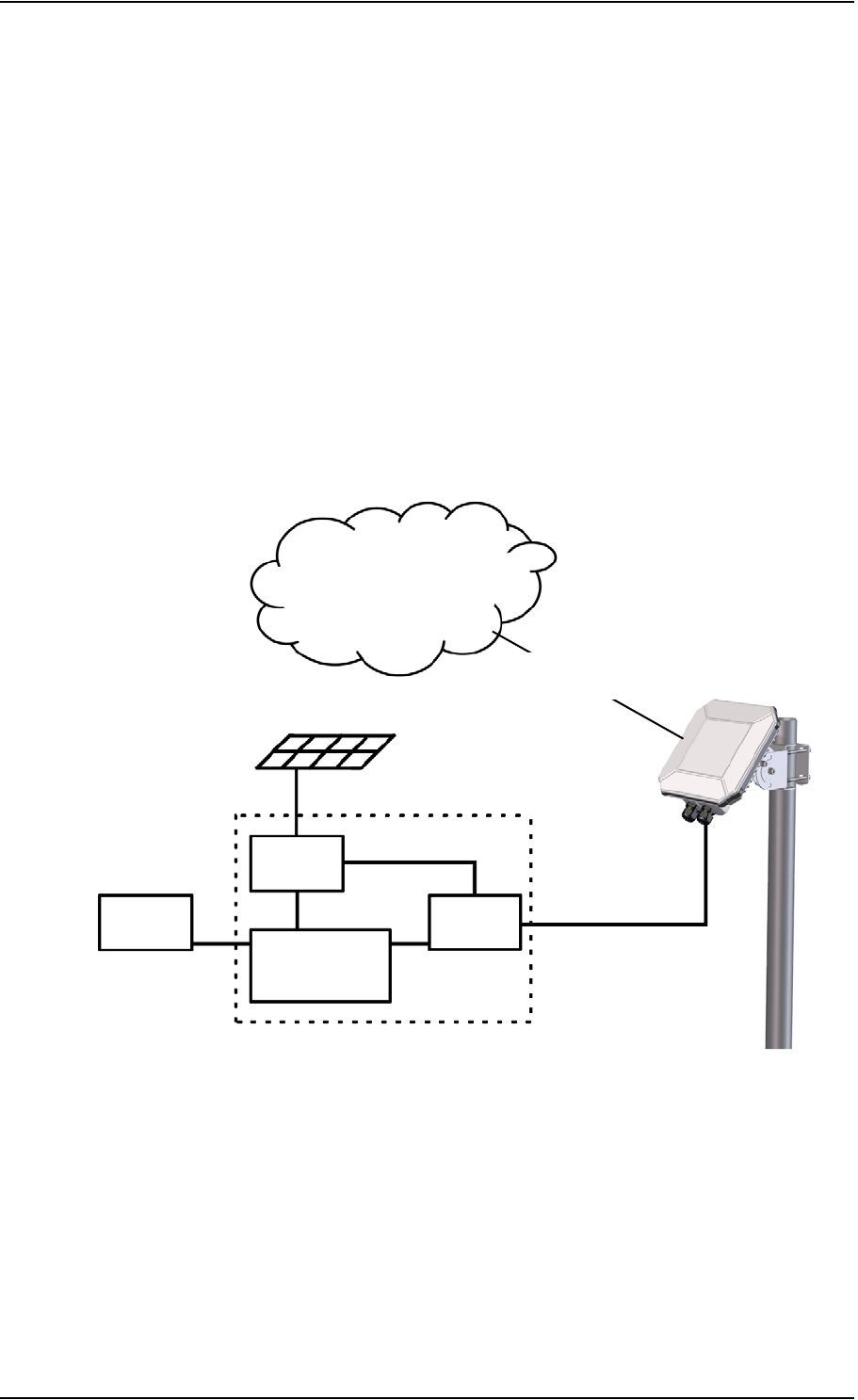
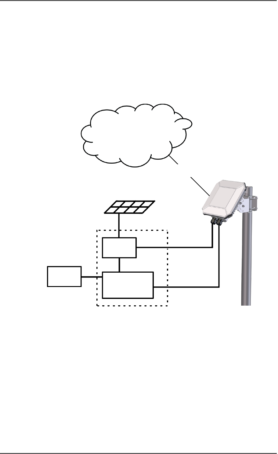
M2M overview, example
In the example below, the M2M system has a built-in PoE switch, providing the power to the
EXPLORER 540 together with the M2M communication through the LAN interface.
Note
The EXPLORER 540 works as a Powered Device (PD), that is it may be powered by PoE,
but it does not supply PoE.
M2M equipment
(including PoE source)
Internet
BGAN M2M service
via satellite
LAN with PoE

98-148232-B To unpack the EXPLORER 540 7
Chapter 2
To get started 2
This chapter describes:
•To unpack the EXPLORER 540
•SIM card
•Cable connections
•Fixed installation of the EXPLORER 540
•To power the EXPLORER 540
•Installation process
•To access the web interface
•M2M application examples
To unpack the EXPLORER 540
Initial inspection
Inspect the shipping carton immediately upon receipt for evidence of damage during
transport. If the shipping carton is severely damaged or water stained, request that the carrier's
agent be present when opening the carton. Save the carton packing material for future use.
After unpacking the system, inspect it thoroughly for hidden damage and loose components or
fittings. If the contents are incomplete, if there is mechanical damage or defect, or if the
system does not work properly, notify your dealer.
WARNING! To avoid electric shock, do not apply
power to the system if there is any sign of shipping
damage to any part of the front or rear panel or the
outer cover. Read the safety summary at the front of this
manual before installing or operating the system.
Chapter 2: To get started
98-148232-B SIM card 8
What’s in the delivery
The following items are included in the delivery:
•EXPLORER540 terminal
•Pole mount kit
• 2 Cable glands and 1 Blind plug
• Torx bit for mounting/dismounting the cover for the interface enclosure
• Installation guide
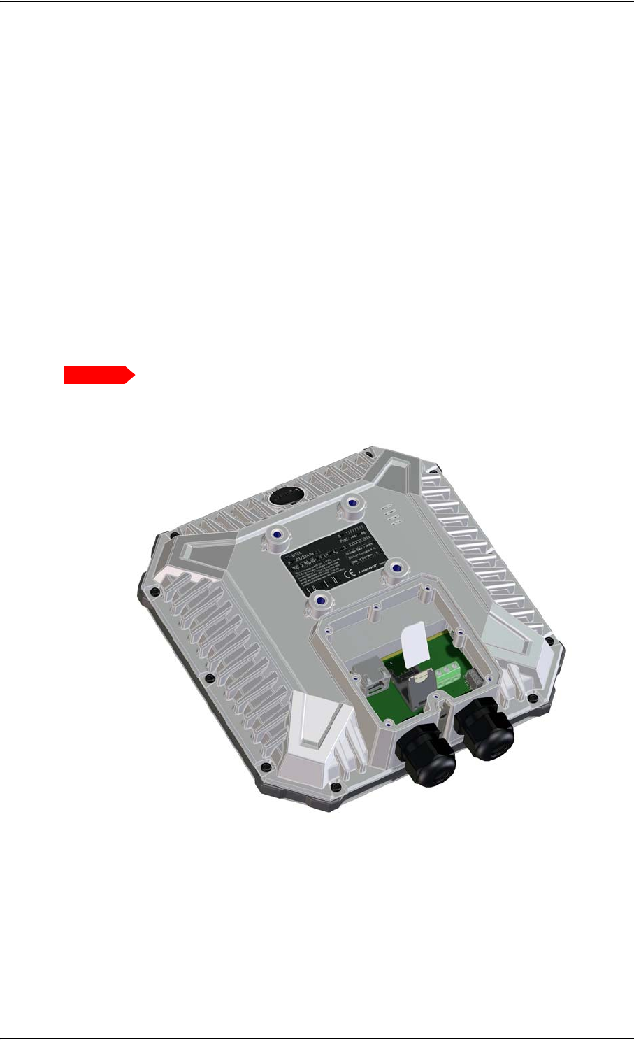
SIM card
The SIM card determines whether the terminal operates as an M2M terminal or a standard
BGAN class 2 terminal.
You insert the SIM card before installing the EXPLORER 540. The picture below shows the
location of the SIM card holder, in the interface enclosure at the back of the terminal.
For details on how to insert the SIM card, see the installation guide.
Important
Do not insert or remove the SIM card while the EXPLORER 540 is powered!
Chapter 2: To get started
98-148232-B Cable connections 9
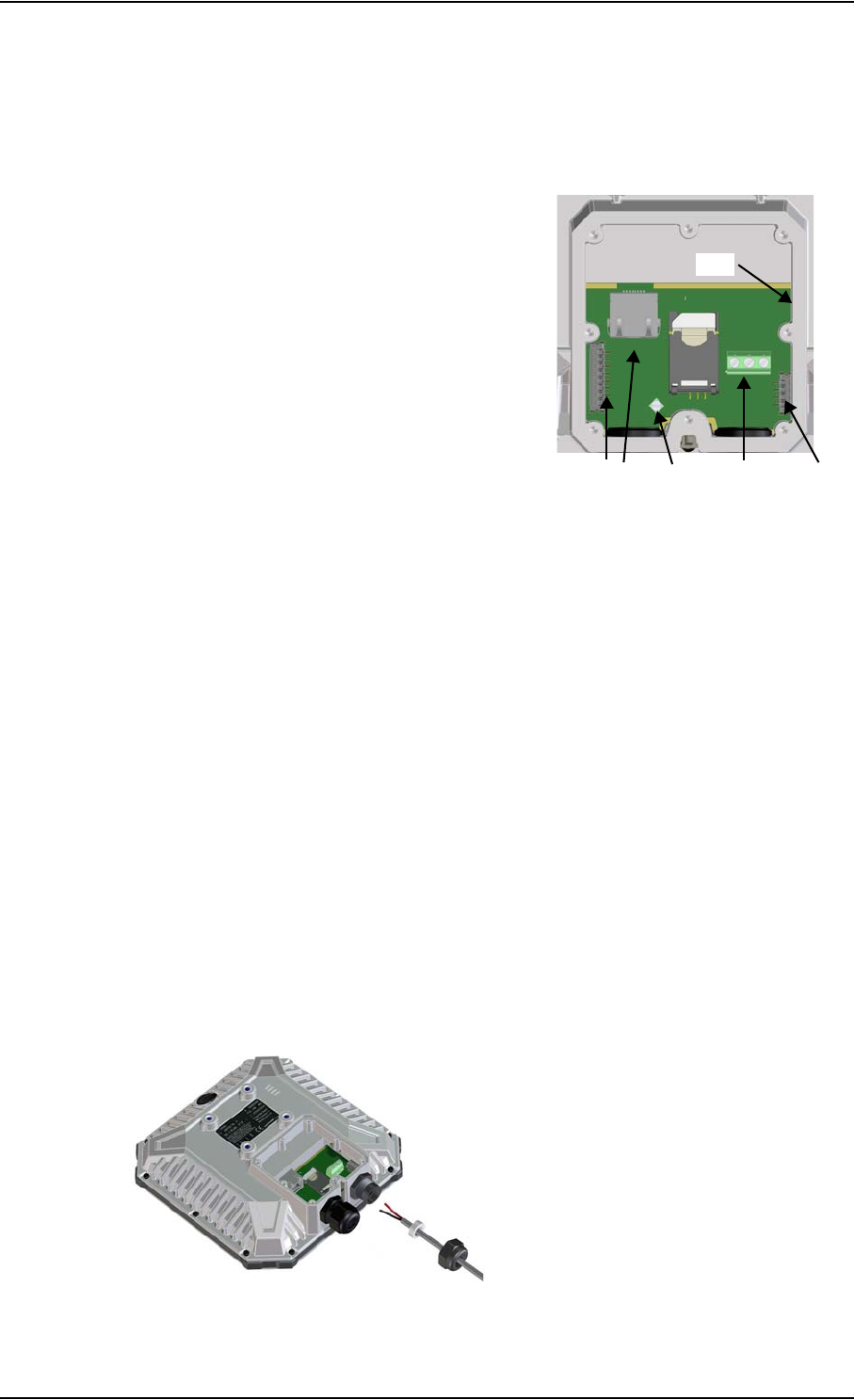
Cable connections
There are no external connectors on the EXPLORER 540. All cable connections on the
EXPLORER 540 are made during installation.
Remove the small cover at the back of the terminal and
connect the cables to the relevant terminals or
connectors. Two cable glands with gaskets are provided
for the cables.
See Interfaces specifications on page 90 for
specifications and pin-out for the interfaces.
See the section below for instructions specific to the DC
input.
See the installation guide for details on how to connect
cables in the EXPLORER 540.
Instructions for DC input
Requirements
Observe the following requirements for connecting to the DC input:
• Power supply: Use only fused or current limiting power supply.
•Cable requirements:
• Wire size: 1.5 mm2
• Temperature rating: Min. 105 °C
• Max. length: 12 m at 12 VDC, 200 m at 24 VDC
• UV resistant cable
To connect to the DC input
Use a flat blade screw driver (max. 3.5 mm wide) to unscrew and fasten the screw terminals. Do
as follows:
1. Lead the cable through the cable gasket at the DC input.
DC inputLAN I/O
USB
GND
Chapter 2: To get started
98-148232-B Fixed installation of the EXPLORER 540 10
2. Insert the positive wire into the terminal marked 1-DCIN+ in the DC terminal block and
tighten the screw.
3. Insert the negative wire into the terminal marked 2-DCIN- in the DC terminal block and
tighten the screw.
4. If the DC cable is shielded, insert the end of the shield into the terminal marked 3-GND in
the DC terminal block and tighten the screw.
5. Tighten the cable gland.
Fixed installation of the EXPLORER 540
To install the EXPLORER 540 in a fixed installation, use the pole mount kit included in the
delivery.
For details on how to install the EXPLORER 540, see the included installation guide.
To power the EXPLORER 540
The EXPLORER 540 has no power switch, but is automatically switched on when power is
applied to the DC input or the LAN interface.
Use one of the following power sources (connected at installation, see the Installation guide):
• PoE+ via the LAN interface
• 12 or 24 VDC nominal, e.g. from a battery (absolute maximum rating 10.5-32 VDC)
Important
Make sure all cables are connected and the Installation process for satellite
operation is completed before you fasten the EXPLORER 540 in your fixed
installation.
Chapter 2: To get started
98-148232-B Installation process 11
Installation process
Physical installation
See also the supplied Installation guide.
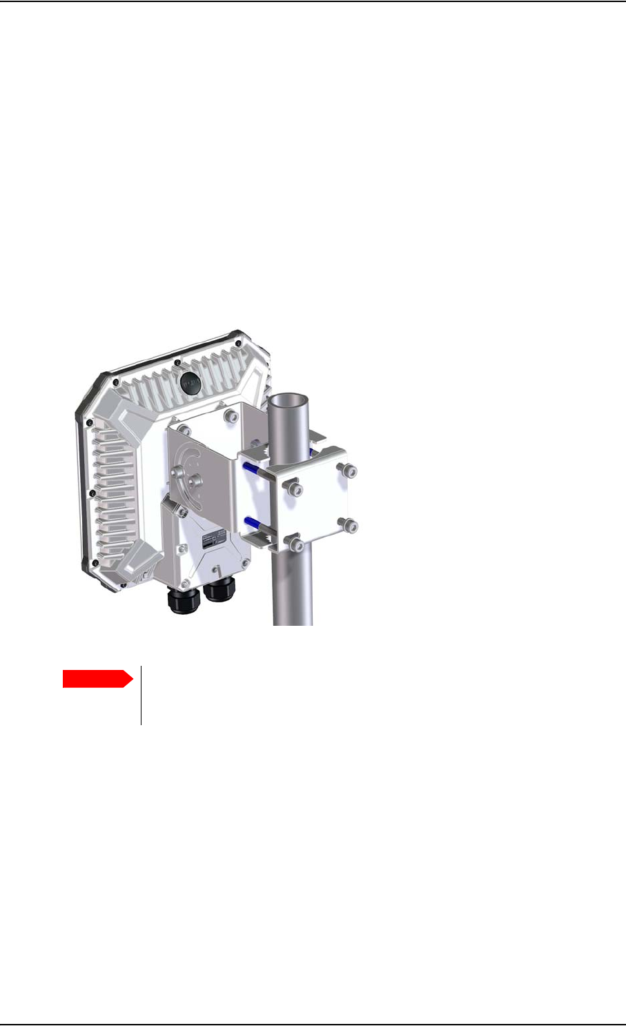
A pole mount kit is included in the delivery. To mount the
EXPLORER 540 on a pole, do as follows:
1. Attach the base of the pole mount bracket to the
EXPLORER 540 using the included Hex L key on the 4
screws. Caution! Max. length of the screws is 9 mm!
Longer screws can damage the EXPLORER 540.
2. Unscrew two of the long screws from the pole mount
kit to leave one side open for the pole.
3. Place the pole mount kit with the EXPLORER 540
around the pole as shown.
4. Remount the two remaining long screws. Do not
tighten the screws completely until you have pointed
the antenna.
Pointing
Before pointing the antenna you can use the coverage map below to find your approximate
location in relation to the satellites. Pointing is part of the Installation procedure described in
the next section.
The Inmarsat satellites are positioned above the equator, at the centre of each “footprint”.
Chapter 2: To get started
98-148232-B Installation process 12
Installation process for satellite operation
The installation process starts up automatically when you apply power to the EXPLORER 540.
The process is as follows:
1. Apply power to the EXPLORER 540 from a separate power supply or from a PoE source.
The light indicator between the two cable glands shows the status during startup.1
• Green flashing rapidly: Starting up
• Yellow flashing: BGAN pointing
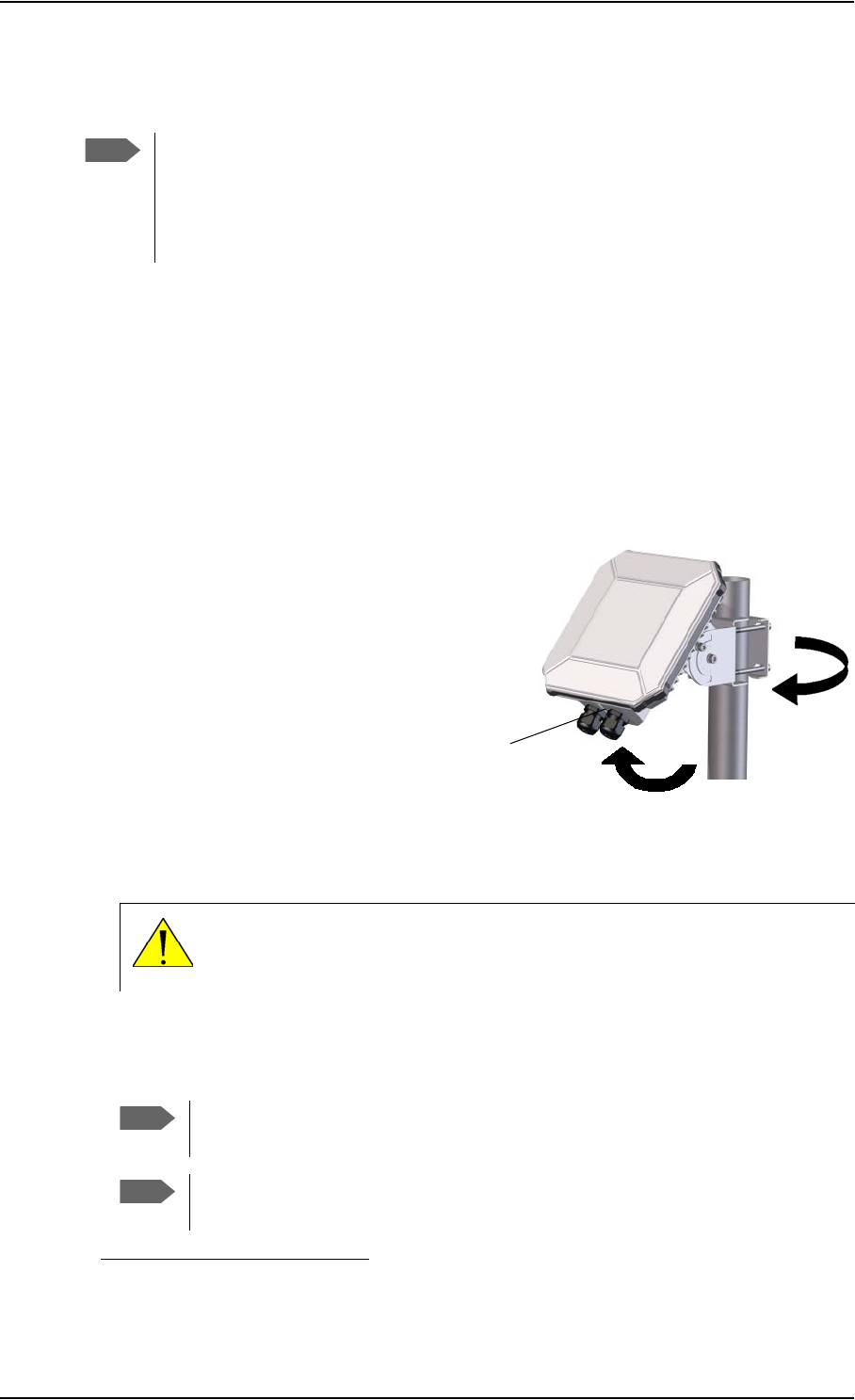
2. When the indicator flashes yellow and you hear the pointing sound, you can start pointing
the antenna.
3. Turn and tilt the EXPLORER 540
until you have obtained the highest
possible signal strength (when the
pointing sound is continuous you
have the optimum signal, see the
next section Audio assisted
pointing).
4. Tighten the screws to fix the
EXPLORER 540 in the pointed
position.
When the signal has been stable for about 20 seconds the pointing procedure
automatically ends, and the terminal attempts to register on the network and verify the
satellite connection (indicator flashing green).
5. When installation is completed successfully, the light indicator turns steady green and
then, after a few minutes, the light goes off. If you have enabled automatic activation, the
data connection is established automatically.
Note
Normally you are not required to enter a PIN code for the BGAN service, because the
SIM PIN is either disabled or set up for automatic validation. However, if the PIN is
enabled and not set up for auto validation, you have to enter the PIN before you can
access the BGAN network. For details, see To enter the SIM PIN in the web interface
on page 74.
1. If you have a computer connected to the EXPLORER 540, you can follow the process in
the web interface, see To restart the installation process on page 47.
CAUTION! When the connection is established, keep the minimum safety
distance of 1 m from the antenna front face. The antenna radiates
microwave power as soon as the pointing procedure is completed.
Note
The LED is always off after successful installation, even after reboot! The LED
only comes on again if you restart installation.
Note
If the LED is steady yellow after pointing, the installation failed. See
Troubleshooting on page 78.
Light
indicator

Chapter 2: To get started
98-148232-B Installation process 13
6. The EXPLORER 540 is now ready for use. For details on how to access the EXPLORER 540
from a remote location, see To access the terminal from a remote location on page 20.
After successful installation, the EXPLORER 540 will automatically register on the BGAN
network at every power-up and, if automatic activation is enabled, establish a data connection
again. This is also the case following one of the “wake-on” actions after power save.
Audio assisted pointing
By default, the EXPLORER 540 uses a pointing sound to indicate the signal level during the
pointing procedure (Audio assisted pointing). The sound pattern is as follows:
• Poor signal strength: • • • •
• Good signal strength: •••••••••••••••••••
• Optimum signal strength: (continuous sound instead of single “beeps”)
You can disable the pointing sound using the web interface. For details, see To enable or
disable the pointing sound on page 52.
To repoint the antenna
You may need to point the antenna again later, e.g. if the terminal has been moved or the
signal is blocked.
To start the installation process again, you can do one of the following:
• Use the web interface ( (Control panel) and then Installation). See To restart the
installation process on page 47.
• Reset the EXPLORER 540 using the Reset button inside the interface enclosure on the back
of the terminal. See Reset button on page 77.
Do you need a PIN?
To avoid having to enter a PIN at startup, you have two options:
•Enable Auto SIM PIN validation. See Auto SIM PIN validation on page 64.
With this option enabled, the EXPLORER 540 automatically sends the PIN to the SIM card
at every startup. Note that if you later want change the SIM card, you should first disable
Auto SIM PIN validation.
• Disable the use of a SIM PIN. See To enable or disable the use of a SIM PIN on page 64.
When the SIM PIN is disabled, the SIM can be used by other terminals without a PIN.
If you are using a SIM PIN in your system, you can enter the SIM PIN from the built-in web
interface. For details, see To enter the SIM PIN on page 74.
Important
If your EXPLORER 540 is used in an unmanned M2M system, you will not be able
to enter a PIN code. In this case we strongly recommend enabling Auto SIM
PIN validation in the web interface before using the system. See below.
Note
If you are asked for a PIN in the web interface and you select Cancel, you cannot
communicate on the network, but you can access all settings.

Chapter 2: To get started
98-148232-B To access the web interface 14
To access the web interface
You can use the built-in web interface for configuration and operation of the EXPLORER 540.
To access the web interface, do as follows:
1. Start up the terminal.
2. Connect your computer to the LAN interface of the terminal. If the terminal is already
installed in your system, you must connect via a router or switch, because there is only one
LAN interface on the EXPLORER 540.
3. Open your browser and enter the IP address of the terminal in the address bar. The default
IP address of the terminal is 192.168.0.1.
4. Log in as user or administrator. Default user names and passwords are:
•user: User name = user, password = <serial number of the EXPLORER 540>
•administrator: User name = administrator, password = admin
If the terminal is not yet installed, it will automatically start the installation procedure and the
web interface will show the progress. Otherwise the web interface will show the dashboard.
For more information on the web interface, see The web interface on page 39.
Important
Remember to change the administrator password! See To change the
administrator password on page 62.
Chapter 2: To get started
98-148232-B M2M application examples 15
M2M application examples
When an M2M SIM card is installed, the EXPLORER 540 uses the BGAN M2M service (see
BGAN M2M services on page 5).
If a PoE switch is not included in the connected M2M equipment, you must provide power
either through the LAN interface with a PoE injector or a PoE switch connected, or from a
battery connected to the DC input. The following sections show examples.
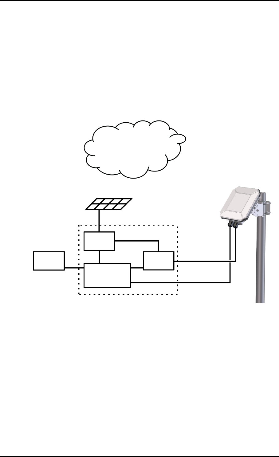
PoE injector
The picture below shows an example of an M2M application using a PoE injector to provide
the power to the EXPLORER 540 through the LAN interface. Note that the PoE injector must
comply with the requirements for PoE+ IEEE 802.3at type 2 class 4. The PoE injector is
connected to a power supply and “adds” power to the LAN connection for the EXPLORER 540.
For specifications and pinout for the LAN interface on the EXPLORER 540, see LAN interface
(X1 or X2) on page 90.
PoE
injector
M2M
equipment
Internet
LAN LAN w. PoE
Battery
Probe
Solar panel
DC power
BGAN M2M service
via satellite
Chapter 2: To get started
98-148232-B M2M application examples 16
Separate battery supply
Another example is the scenario below, where power is supplied from a separate battery
connected to the DC input of the EXPLORER 540. This solution may be used e.g. if you want to
limit the power consumption, or if a PoE source is not available. For specifications and pinout
for the DC input on the EXPLORER 540, see DC power input (X4) on page 91.
For installation instructions, see the supplied EXPLORER 540 Installation guide. Note that you
must use a fused or current-limiting DC power supply (battery).
Battery
M2M
equipment
Internet
BGAN M2M service
via satellite
LAN
DC power
Solar panel
Probe
Chapter 2: To get started
98-148232-B M2M application examples 17
I/O pins
The EXPLORER 540 has 3 I/O pins, two assigned pins and 1 general purpose pin.
• Request wake up (input)
• Terminal ready (output)
• Control/Status input/output
The Control/Status input/output can be configured (input/output and high/low) using the web
interface, and with AT commands you can control or read the status of the pin. For details on
the I/O pins, see I/O pins (Settings) on page 72 and I/O connector (X5) on page 91.
.
PoE
injector
M2M
equipment
Internet
LAN LAN w. PoE
Battery
Probe
Solar panel
DC power
BGAN M2M service
via satellite
I/O

98-148232-B Local or remote control 18
Chapter 3
Operation 3
This chapter describes operation and basic setup, primarily for M2M use.
For information on configuration with the web interface, see Configuration with web
interface on page 38.
This chapter describes:
•Local or remote control
•To access the terminal using AT commands
•To access the terminal from a remote location
•Security setup
•To control data connections (PDP contexts)
•Power-saving
•Remote software upgrade
•File transfer
•Status of the EXPLORER 540
For information on functions that are not available with an M2M subscription but only with a
standard BGAN subscription, see BGAN non-M2M functions on page 108.
Local or remote control
The EXPLORER 540 can be controlled both locally using the LAN interface and from a remote
location over the BGAN network. For M2M operation, remote control is essential, since the
EXPLORER 540 is most likely installed in a remote location where local human access is rare and
maybe difficult.
Note that different levels of access control apply to different means of access. See Security
setup on page 27.
You have the following options:
Local control:
• web interface: Connect a computer to the LAN interface and use a browser to access the
built-in web interface. See Configuration with web interface on page 38.
• AT-commands: Connect a computer to the LAN interface and use a terminal program to
send commands to the EXPLORER 540 or connect other equipment capable of issuing AT
commands to the EXPLORER 540 (e.g. in an M2M application). See To access the terminal
using AT commands on page 19.

Chapter 3: Operation
98-148232-B To access the terminal using AT commands 19
Remote control:
• SMS commands: You can use SMS commands e.g. to start and stop your data connection
and send and receive AT commands to and from the terminal. See Remote access with
SMS on page 20.
• AT commands: When a data connection is established you can control the EXPLORER 540
with AT commands over the BGAN satellite network. See To access the terminal from a
remote location on page 20 and To access the terminal using AT commands on page 19.
• web interface: When a data connection is established you can control the EXPLORER 540
over the BGAN satellite network by accessing the built-in web interface. See Remote
access to the web interface on page 25.
• The distributors may have their own Graphical User Interface, which could be built on e.g.
Inmarsat's M2M API or similar. Contact your distributor for information.
To access the terminal using AT commands
The EXPLORER 540 supports a number of M2M specific AT commands as well as a set of
general AT commands. For a list of the most common commands, see AT commands on
page 99.
AT commands can also be encapsulated in an SMS sent to (and from) the terminal’s phone
number. See Remote access with SMS on page 20.
1. Connect your computer (or M2M equipment) to the EXPLORER 540 terminal.
You may connect locally to the terminal or use a remote connection.
2. On the connected computer, start a Telnet session.
3. Select TCP/IP and type in the IP address and port number.
•For local connection, use the local IP address of the EXPLORER 540 (default
192.168.0.1) and port number 5454.
•For remote connection, use the external IP address1 of the terminal. The port number
for AT commands is normally 5454 but can be changed in the web interface Remote
management page under AT commands (see Remote management on page 68).
Important
Before putting the EXPLORER 540 into operation, remember to set up the
security features in order to avoid unintended use. See Security setup on
page 27.
1. The external IP address is found in one of the following ways:
1. If you are using SMS activation, you will receive an SMS with the IP address.
See ACTIVATE: Activate a data connection with an SMS on page 21
2. Otherwise, you can use the GETINFO (ALL) command to obtain the external IP address, if you
already have a session running.
This is the IP address you must use to access the terminal.
Note: If Static IP is included in your airtime subscription, we recommend using this static public
IP address for the terminal in order to provide easy access to the terminal. To use the static IP
address, you must set the APN source to SIM default. For details, see To change the APN for a
connection package on page 43.

Chapter 3: Operation
98-148232-B To access the terminal from a remote location 20
4. When the connection is established, type in your AT commands. Note that you have to
enter the administrator password with the AT_ICLCK command. See Security setup on
page 27.
To access the terminal from a remote location
Remote access with SMS
You can perform a number of actions and some configuration on the EXPLORER 540 using
SMS commands.
Send an SMS to the mobile number of the terminal. The text in the SMS must start with the
SMS command and follow the syntax for the SMS commands. Note that the remote SMS
password (default: remote) must be included with every command.
For an explanation of syntax and parameters, see SMS remote commands on page 95.
Note that the remote SMS function is password protected.
The following SMS commands are supported.
The next sections show examples of each SMS command.
Important
By default, any phone number can access the EXPLORER 540 with an SMS, if
they have the phone number of the terminal and the remote SMS password.
Before installing the EXPLORER 540 you should set up the security measures for
the terminal. See Security setup on page 27 and To set up remote access with
SMS on page 69.
SMS command Function
ACTIVATE Activates data connections for the device(s) connected to the
EXPLORER 540
DEACTIVATE Deactivates some or all the data connections for devices connected to
the EXPLORER 540
CLEAR Deletes SMS messages in the EXPLORER 540
GETINFO Retrieves current information from the EXPLORER 540 such as call time,
data usage, GPS position and global IP address.
RESTART Restarts the EXPLORER 540
WATCHDOG Requests or allows you to modify the current Watchdog settings (called
Link monitoring in the EXPLORER 540)
ATCO Allows you to send M2M related AT commands to the EXPLORER 540
which returns the response in an SMS
ADPWRST Resets the EXPLORER 540 admin password to admin

Chapter 3: Operation
98-148232-B To access the terminal from a remote location 21
ACTIVATE: Activate a data connection with an SMS
The text in the activation SMS must have the following format for activating a connection:
ACTIVATE 1 {DHCP|STATIC|<name>|<IP addr>|ANY} {NA|<apn>}
{NA|<apn_user>} {NA|<apn_pwd>} <rsms_pwd>
Example: To activate one or more connections for remote management for connected
equipment with IP address(es) assigned by DHCP, using default settings (NA) for
APN, APN user name and APN password, send an SMS to the terminal with the text:
ACTIVATE 1 DHCP NA NA NA remote
Response:
You receive a response with the IP address you must use to access the terminal from a remote
location.
Example: A confirmation SMS after sending an activation SMS may look like this:
IP: 161.30.181.31 (192.168.128.104)
SMS-Free: 88/100
WARNING: Ensure SMS-free > 5. Cleanup old msgs for
orderly remote-SMS-control
The first IP address is the global IP address assigned to the PDP context by the network, and
the second IP address (in parenthesis) is the IP address (or host name, if the device was
identified by host name) of the device connected on the local LAN, for which the PDP context
was created.
DEACTIVATE: Deactivate a data connection
The text in the deactivation SMS must have the following format for deactivating a
connection:
DEACTIVATE 1 {DHCP|STATIC|AWO|<name>|<IP addr>|ANY} <rsms_pwd>
Example: To deactivate connections for all DHCP IP addresses, send an SMS to the terminal
with the text: DEACTIVATE 1 DHCP remote
Response:
You receive a response showing the IP address(es) for which the connection was deactivated.
Example: A confirmation SMS after sending a deactivation SMS may look like this:
LOCAL IP 192.168.128.104 DEACTIVATED
SMS-Free: 77/100
WARNING: Ensure SMS-free > 5. Cleanup old msgs for
orderly remote-SMS-control
Note
The following examples use the default remote SMS password, which is remote. the
password may be different in your EXPLORER 540.

Chapter 3: Operation
98-148232-B To access the terminal from a remote location 22
CLEAR: Delete SMS messages in the EXPLORER 540
The text in the CLEAR SMS must have the following format:
CLEAR <category> SMS <rsms_pwd>
Example: To delete all SMS messages from the EXPLORER 540, send an SMS to the terminal
with the text: CLEAR 4 SMS remote
Response:
No response is sent for this command.
GETINFO: Retrieve information from the EXPLORER 540
The text in the GETINFO SMS must have the following format:
GETINFO <info_mode> {GPS|ALL|USAGE} <rsms_pwd>
Example: To request all information with titles, send an SMS with the text:
GETINFO 1 ALL remote
Response: The response depends on the requested format (GPS/ALL/USAGE) and info mode.
For the command in the example, the response would have the titles shown below.
Example: IMSI: 901112112456789
IMEI: 35393803001003
LAT: 32.89495
LON:-117.20205
SW: 1.0
C/N0: 66
Beam: 84
Uptime: 59483
GIP: 161.30.23.43
The Uptime is in seconds, and GIP is the global IP address of the first active PDP context.
RESTART: Restart the EXPLORER 540
The text in the RESTART SMS must have the following format:
RESTART 1 BGAN <rsms_pwd>
Example: To restart the EXPLORER 540, send an SMS with the text:
RESTART 1 BGAN remote
Response:
No response is sent for this command.

Chapter 3: Operation
98-148232-B To access the terminal from a remote location 23
WATCHDOG: Request or modify watchdog settings
The text in the WATCHDOG SMS must have the following format:
WATCHDOG <wdog_op> <ping1> <ping2> <ping3> <ping_ always> <ping_ interval> <wdog_
enable> <rsms_pwd>
Example: WATCHDOG 2 100.100.100.130 100.100.100.110 200.247.237.254 0 20 1
remote
In this example, Link monitoring is set up as follows:
2: Set watchdog parameters
100.100.100.130: Primary IP address
100.100.100.110: Secondary IP address
200.247.237.254: Tertiary IP address
0: Send ping only if no IP data traffic
20: Ping interval (number of minutes between pings)
1: Enable watchdog
remote: Remote SMS password
Response:
You do not get an OK response. You can use the WATCHDOG 1 command to get the status of
the WATCHDOG feature.
See also Link monitoring (watchdog) on page 29.
ADPWRST: Reset the administrator password
To reset the administrator password you need the IMEI number of your terminal. If you can
access the web interface, you can find the IMEI number under Support > Extended status,
see To view extended status on page 60.
The text in the ADPWRST SMS must have the following format:
ADPWRST 1 <imei> <rsms_pwd>
Example: To reset the administrator password of a terminal with the IMEI number 363833-
09-012345. send an SMS with the text:
ADPWRST 1 36383309012345 remote
Response:
You receive a response with the result of the action.
Example: A response for a successful ADPWRST command, could be:
ADMIN RESET SUCCESS
SMS-Free: 88/100
WARNING: Ensure SMS-free > 5. Cleanup old msgs for
orderly Remote SMS Control

Chapter 3: Operation
98-148232-B To access the terminal from a remote location 24
ATCO: Send AT commands to the EXPLORER 540
The text in the ATCO SMS must have the following format:
ATCO <resp_mode> <rsms_pwd> <at_cmd>
Example: To command the EXPLORER 540 to download new software from the default FTP
server via the default APN and upgrade to the new version immediately, send an
SMS with the text:
ATCO 2 remote _IGETFW=1
Response:
You receive a response with the result of the action. In this example we have chosen to see
only the final response (<resp_mode> = 2) and we have chosen immediate upgrade
(<mode> =1), so the final (and only) response will be related to the upgrade of the
EXPLORER 540.
Example: For a successful completion of the command in the above example, the response
would then be: _IUPDFW: 0, Complete
See also ATCO response codes on page 102.
List of supported ATCO commands:
The following AT commands are supported using the ATCO command in an SMS. For syntax
and parameters, see ATCO commands on page 100.
•_IGETFW Get new firmware (and optionally install it)
See Remote software upgrade on page 33
•_IUPDFW Update the terminal with new firmware
See Remote software upgrade on page 33
•_ISENDFILE Send a file from the terminal to an FTP server
See File transfer on page 34
•_IGETFILE Retrieve a file from an FTP server to the terminal
See File transfer on page 34
•_IUPDCFG Update to a new configuration file
See File transfer on page 34
•_IREMWEB Open a connection for remote access to the terminal’s Web interface
See Remote access to the web interface on page 25
•_ICPWD Change the terminal’s admin password
See Security setup on page 27
•_IATCROBST Configure 3GGP LTE robustness feature
Remote access with AT commands
Access the terminal as described in To access the terminal using AT commands on page 19.
You must use the external IP address of the EXPLORER 540.

Chapter 3: Operation
98-148232-B To access the terminal from a remote location 25
Remote access to the web interface
There are two methods of getting remote access to the web interface:
• Using the AT command _IREMWEB, e.g. sent in an SMS (ATCO command)
• Using an EXPLORER 540 that is pre-configured with trusted IP addresses
The following sections describe these two methods.
To use AT commands to get remote access to the web interface
You can send the AT commands encapsulated in an SMS (ATCO commands). For details, see
Remote access with SMS on page 20.
Relevant commands:
_IREMWEB
Se ATCO commands on page 100 for syntax and parameters.
1. To use an SMS to allow access to the web interface for specific IP addresses, send the
following command:
ATCO <resp_mode> <rsms_pwd> _IREMWEB=1,<ip address>[,<ip address>]
Example: ATCO 2 remote _IREMWEB=1, 214.123.189.119
In this example the command specifies no immediate response, only when the global IP
address is sent along (2). The remote SMS password is remote and the IP address
214.123.189.119 can get remote access to the web interface (if two IP addresses are
listed, it is interpreted as a range of IP addresses).
2. The EXPLORER 540 should now return an SMS response with the external IP address of the
terminal.
Example: _IREMWEB:81, GlobalIP:161.30.181.31
81 is the response code for a remote web connection that was set up successfully. It is
followed by the global IP address, which is the IP address to enter in your browser to
access the web interface from the remote device with the IP address you specified in the
command.
3. On the remote computer, open your web browser.
4. In the address bar of your browser, enter the global IP address of the EXPLORER 540
(received in the response above).
Note
When using remote access, the web interface may take a long time to load the pages,
because the Internet connection may be slow.
Note
Only one PDP context at a time can be used for remote web interface access.
Note
If remote SMS command access has been disabled, you can enable it either using the
web interface or using AT commands. See To set up remote access with SMS on
page 69 and To set up the security with AT commands on page 27 (step 4.).

Chapter 3: Operation
98-148232-B To access the terminal from a remote location 26
You should now be connected to the built-in web interface of the terminal.
To get remote access to the web interface from a trusted IP address (preconfigured)
1. Connect a computer to the EXPLORER 540 and access the web interface locally.
2. Prepare the terminal as described in Remote management on page 68.
3. Make sure your remote computer has access to the Internet.
4. On the remote computer, open your web browser.
5. In the address bar of your browser, enter the IP address of the terminal followed by a colon
and the port number
http://<ip address>:<incoming port>.
• <ip address> is the external IP address of the EXPLORER 540. The external IP address can
only be obtained when a data connection (PDP context) is established. If a data
connection is started. you can get the external IP address with the GETINFO SMS
command, see GETINFO: Retrieve information from the EXPLORER 540 on page 22.
• <incoming port> is the port you defined in Remote management on page 68 (Incoming
port for web application, default port 80).
Example: If the IP address of the terminal is 161.30.180.12 and the incoming port number
defined in the Remote management page in the web interface is 80, enter
http://161.30.180.12:80.
You should now be connected to the built-in web interface of the terminal.
Note
Access to the EXPLORER 540 web interface is restricted with a password. See Security
setup on page 27 and Passwords on page 62.
Note
This method requires that you initially have local access to the EXPLORER 540. If not,
use the _IREMWEB command described in the previous section.
Note
Access to the EXPLORER 540 web interface is restricted with a password. See Security
setup on page 27 and Passwords on page 62.

Chapter 3: Operation
98-148232-B Security setup 27
Security setup
Overview of security measures
Since the EXPLORER 540 is most likely placed in remote areas without direct supervision, it is
important to protect it against unauthorized access.
The EXPLORER 540 has the following security measures:
• User and administrator passwords for the web interface.
• Admin password for AT shell and SMS control.
• White list for SMS control (list of trusted phone numbers).
•MAC filtering
• SIM personalization.
Optional SIM lock (lock to provider) and optional PIN lock (lock to EXPLORER 540
terminal).
• Disable Reset button.
One of the functions of the Reset button is to reset to factory default, which also resets
the administrator password. This function can be disabled using the web interface.
You can set up these security measures in the web interface or with AT commands. see the
next sections for details.
To set up the security with AT commands
For details on how to send AT commands to the EXPLORER 540, see To access the terminal
using AT commands on page 19.
For details on syntax and parameters for the AT commands, see AT commands on page 99.
Do as follows:
1. Disable administration lock:
AT_ICLCK=AD,0,<password>
Example: AT_ICLCK=AD,0,admin
When you get an OK reply you have administrator access to the AT shell.
2. Set new administrator password:
AT_ICPWD=AD,<old password>,<new password>
Example: AT_ICPWD=AD,admin,myadmpwd
When you get an OK reply the administrator password is set to the new password
(myadmpwd in the example).
Important
By default any phone number can access the EXPLORER 540 with an SMS! To
protect against unauthorized access, change the remote SMS password and
make a list of trusted phone numbers. See To set up remote access with SMS on
page 69 and To set up the security with AT commands below.

Chapter 3: Operation
98-148232-B Security setup 28
3. Set new password for remote SMS:
AT_ICPWD=RS,<old password>,<new password>
Example: AT_ICPWD=RS,remote,mysmspwd
When you get an OK reply the password for remote SMS access is set to the new password
(mysmspwd in the example).
4. Disable/enable remote SMS commands:
Disable: AT_ISMSRMT=0
Enable: AT_ISMSRMT=1
5. Specify a white list of trusted MAC addresses:
AT_IMACLOCAD=1,0,<MAC address>[,<MAC address> (etc.)]
Example: AT_IMACLOCAD=1,0,00:B5:E0:76:FD:C2,00:B5:A0:84:F9:E2
When you get an OK reply, the specified MAC addresses are added to the white list.
6. Turn on MAC address filtering:
AT_IMACLOC=1,0
When you get an OK reply, MAC address filtering is enabled for Ethernet, and only the
MAC addresses specified in the white list can get access (previous step).
7. Enable administration lock:
AT_ICLCK=AD,1,<password>
Example: AT_ICLCK=AD,1,myadmpwd
When you get an OK reply, the system is protected with the administrator password.
To set up the security with the web interface
If you want to setup the security with the web interface, see the following sections:
• User and administrator passwords for web interface: Passwords on page 62
• Admin password for AT shell (same as for web interface): Passwords on page 62
• Password for remote SMS access: To set up remote access with SMS on page 69
Note
The password cannot contain spaces, e.g. “new pw” is not accepted, whereas
“new_pw” is accepted.
Important
If you disable remote SMS commands there is no way to access the terminal
remotely, unless you have an open data connection (PDP context)! Instead
we recommend to define a set of trusted phone numbers, see To set up
remote access with SMS on page 69.
Note
Until MAC address filtering is enabled, all MAC addresses are allowed and the
white list has no effect.
Important
Remember to add the MAC address of your own device. Enabling the MAC
address locking without adding your own device MAC address will block for
any local access to the Terminal!

Chapter 3: Operation
98-148232-B To control data connections (PDP contexts) 29
• Trusted phone numbers for SMS control: To set up remote access with SMS on page 69
•MAC filtering: To manage connected devices (Traffic control) on page 54
• SIM personalization: Auto SIM PIN validation on page 64 and SIM lock on page 65
• Disable Reset button: Reset button on page 73.
To control data connections (PDP contexts)
Automatic Context Activation (ACA)
In the web interface you can set up the EXPLORER 540 to automatically establish a data
connection when it is registered on the satellite network. See To set up the connection mode
step 3. on page 51. In the web interface ACA is called “Automatic activation”. Automatic
activation also applies to the “wake-on” actions after power save mode (see Power-saving on
page 31) and by recovery after e.g. loss of power.
Link monitoring (watchdog)
It is strongly recommended to use link monitoring to monitor your locally established IP
connection, as it enables you to test the BGAN connectivity and to keep your PDP context
alive.
With this feature activated, the terminal will send out ping commands to up to three servers of
your choice. When a data session is started, the terminal will start sending ping commands to
the Primary IP address the number of times specified. If no response is received, it will send the
same number of ping commands to the Secondary and then Tertiary IP address, if available. If
no response is received from any of the IP addresses, the terminal will eventually restart.
For configuration with the web interface, see Link monitoring on page 66.
For configuration with SMS command, see WATCHDOG: Request or modify watchdog
settings on page 23.
Manual activation of data connections
You can manually activate a data connection in the following ways:
• Remote: Send an SMS to the EXPLORER 540. See ACTIVATE: Activate a data connection
with an SMS on page 21.
• Local (EXPLORER 540 LAN interface):
• Access the web interface locally and click the tile for the data connection on the
dashboard. See To start and stop data connections on page 42 or
• Send an AT command to the terminal. See To configure the connected equipment for
PPPoE on page 30 (the example), To access the terminal using AT commands on
page 19 and Context management AT commands on page 105.
Note
Link monitoring only applies when the data connection is started locally by
equipment connected to the EXPLORER 540. Data connections started with the SMS
command ACTIVATE cannot be monitored with link monitoring.

Chapter 3: Operation
98-148232-B To control data connections (PDP contexts) 30
PPPoE (Point-to-Point Protocol over Ethernet)
To configure the connected equipment for PPPoE
How to configure your equipment depends on the type of equipment. Refer to the user
documentation of the equipment. As a minimum, you need to configure the user name and
password in your equipment in order to make PPPoE work with the terminal
The user name and password can be left blank (or insert user name: void and password: void).
Then the registration on the Access Point is most commonly done in such a way that the data
connection is established with a dynamic IP address from the airtime provider.
To request a static IP (if subscribed to) from the Access Point you must type in the user name
and password from your airtime subscription.
Note for MAC OS: User name and password are required. For some ISPs you can use user name
void and password void. Contact your airtime provider for further information.
To send commands with PPPoE
You can use the command XBB:<AT String> to send AT commands over PPPoE.
Example: To start a Standard data connection with the Context identifier “1”, type
XBB:AT+CGDCONT=1,ip,bgan.inmarsat.com;+CGEQREQ=1,3
Note that there are two commands involved, +CGDCONT and +CGEQREQ.
+CGDCONT defines the context ID (1), the connection type (IP) and the APN
(bgan.inmarsat.com).
+CGEQREQ starts a data connection for the defined context ID (1) using traffic class Standard
data (3)
Note that because the traffic class is 3 (Standard data), the remaining parameters (max. and
guaranteed bit rates etc.) are omitted. See also Context management AT commands on
page 105.

Chapter 3: Operation
98-148232-B Power-saving 31
Power-saving
There are two methods to save power in the EXPLORER 540.
•Sleep mode
•Power save mode
Sleep mode
When in sleep mode the terminal is registered, attached and capable of exchanging data
between the LAN and the BGAN satellite interface.
The system enters sleep mode whenever possible, i.e. if it is not active and not in power save
mode.
Power save mode
In Power save mode, the terminal deregisters and gracefully closes down the terminal to save
power.
To use the Power save mode you must configure one or more “wake up” methods:
•Wake up on daily basis
• Wake up on input pin (dedicated I/O pin)
General power save settings:
• Set the number of minutes without any activity (Idle time) before the terminal enters
power save mode
• Set whether or not the power save function should be prevented when a satellite
connection (PDP context) is open (only configurable with web interface)
You can also configure the wake up methods and the general power save settings in the web
interface. See Power save (Settings) on page 71.
To set the idle time before power save
If you are using Power save mode and none of the conditions that prevent Power save mode
are present (mentioned in the note above), the system will go into Power save mode after a
defined idle time.
Note
The following conditions will prevent the terminal from entering Power save mode:
• The web interface is open
• Data/SMS traffic
•Software update ongoing
• Incoming/outgoing calls
• Wake up input pin (GPI-1) active
Note
If the Idle time is set to “0”, the Power save function is disabled!

Chapter 3: Operation
98-148232-B Power-saving 32
For configuration with AT commands, use the AT command _IPWSAVSCHD as follows:
1. Set the idle time before power save:
AT_IPWSAVSCHD=<psmode>,<psvalue>
Example: AT_IPWSAVSCHD=IDLE_TRG,15
In this example, the power save mode is idle time (IDLE_TRIG), and the idle time before
the terminal enters power save mode is 15 minutes.
For configuration with the web interface, see Power save (Settings) on page 71.
Wake up on daily basis
Daily wake up is a method to save power by setting a timer to regularly wake up the terminal.
When this is used in combination with the output pin that reflects whether the terminal is
awake, it allows for power efficient regular operation of M2M equipment, e.g. for transmission
of environmental probe measurements. For information on the “Terminal ready” output pin
see I/O connector (X5) on page 91.
To configure wake up on daily basis
For configuration with AT commands, use the AT command _IPWSAVSCHD as follows:
1. Set the time of day that the terminal must wake up from power save:
AT_IPWSAVSCHD=<psmode>,<psvalue>
Example: AT_IPWSAVSCHD=TOD_TRG,24:00
In the example above, the power save mode is the Time Of Day (TOD), and the time of day
to wake up from power save is 24:00.
For configuration with the web interface, see Power save (Settings) on page 71.
Wake up on input pin (GPI)
The Request wake up pin (pin 1, input) allows the M2M equipment to signal to the terminal
whether it should wake up (active) or attempt to go into power save mode.
In the web interface you can:
• Enable/disable the input pin
• select the polarity of the input pin (Active high/low).
See Power save (Settings) on page 71 and I/O connector (X5) on page 91.
Important
Remember to configure minimum one of the wake up functions described below
- otherwise the EXPLORER 540 will not be able to enter power save mode.
Note
If the wake-up time of day is set to “0”, the “Wake up time of day” function is
disabled!

Chapter 3: Operation
98-148232-B Remote software upgrade 33
Remote software upgrade
User initiated software upgrade
You can initiate a remote software upgrade with an AT command, either from the command
interface or encapsulated in an SMS (ATCO command).
_IGETFW tells the terminal to get software from an FTP server and either upgrade the
terminal software or download the software file to the terminal for later upgrade.
_IUPDFW tells the terminal to upgrade its software to the downloaded file.
For Syntax and parameters, see ATCO commands on page 100.
To upgrade the software
If you have an M2M subscription, the EXPLORER 540 should be available from the Inmarsat
FTP server. If not, download the new software1 or acquire the software from Cobham
SATCOM and place it on your FTP server.
1. To access the EXPLORER 540, use one of the following:
• a computer connected to the Internet, see Remote access with AT commands on
page 24, or
• equipment connected to a cellular network, see Remote access with SMS on page 20.
Note that you need a password for both access methods. For AT commands, use the
AT_ICLCK command with the admin password, for SMS, use the remote SMS password.
2. Use the command _IGETFW to initiate the software download (and maybe upgrade)
from the specified FTP server. If you are using default APN and default FTP server these
can be left out.
Example: AT_IGETFW=1
In this example, the terminal will get the software from the default FTP server via the
default APN and download and then upgrade the software in the terminal.
3. The terminal prepares for software update, connects to the specified FTP server and
downloads the software image.
If you have selected Deferred update (_IGETFW=0), you have to use the command
_IUPDFW followed by the file name when you want the terminal to upgrade the
software.
Note
FTP server: With M2M subscription you can use Inmarsat’s M2M FUP server (default
FTP server for software upgrade). This is not available for Non-M2M subscriptions.
1. You can download the software from the “Self Service Centre” at www.cobham.com/satcom,
select Service and Support > Cobham SATCOM Service and Support and then 24-7 Self
Service Centre / Technical Downloads. Locate the EXPLORER 540 software.
Note
The Inmarsat FTP server for firmware upgrade is only available with M2M
subscription. If you have a non-M2M subscription you must specify a third party
FTP server for the software upgrade.

Chapter 3: Operation
98-148232-B File transfer 34
4. If you have selected Immediate update (_IGETFW=1), the terminal updates the system,
reboots, installs the update and verifies the online connection.
5. When the software upgrade is successfully completed you get an AT or SMS command
response with the message Complete.
Example:_IUPDFW: 0, Complete
For configuration with the web interface, see To update software on page 60.
File transfer
Using AT commands, you can transfer a configuration file or a log file between the
EXPLORER 540 (local directory in EXPLORER 540 is “/”) and an FTP server over the satellite
network.
_IGETFILE tells the terminal to get a file from an FTP server (e.g. a configuration file)
_ISENDFILE tells the terminal to send a file to an FTP server (e.g. a log file)
_IUPDCFG tells the terminal to update the EXPLORER 540 configuration with the contents of
the previously downloaded configuration file.
For Syntax and parameters, see ATCO commands on page 100.
Configuration file
If you need to reuse a configuration in other terminals of the same type, you can save your
current configuration to a file, which can then be loaded into the other terminal(s).
Save configuration
To command the EXPLORER 540 to save its configuration to a file and transfer it to an FTP
server, do as follows:
1. To access the EXPLORER 540, use one of the following:
• a computer connected to the Internet, see Remote access with AT commands on
page 24, or
• equipment connected to a cellular network, see Remote access with SMS on page 20.
Note that you need a password for both access methods. For AT commands, use the
AT_ICLCK command with the admin password, for SMS, use the remote SMS password.
2. Send the command _ISENDFILE to the EXPLORER 540 to make it send the configuration
file to the specified destination on your FTP server.
Example: AT_ISENDFILE="/","config.txt","ftpdirectory","ftp.my
ftpserver.com","ftp-username","ftp-password"
Note
Be aware that if the terminals have different software versions, some of the settings
may be different than expected. If possible, use the same software version in the
terminals.

Chapter 3: Operation
98-148232-B File transfer 35
In this example. the terminal will look for a file named config.txt in the local directory (/)
in the terminal, and send the file to the directory ftpdirectory on the FTP server named
ftp.myftpserver.com. The user name ftp-username and password ftp-password give
access to the FTP server. The default APN is used (APN info is left out).
3. You get a response command that the file was transferred successfully.
Example: _ISENDFILE: 0, Complete
Load configuration
To command the EXPLORER 540 to update its configuration, do as follows:
1. Place the configuration file on your FTP server.
2. To access the EXPLORER 540, use one of the following:
• a computer connected to the Internet, see Remote access with AT commands on
page 24, or
• equipment connected to a cellular network, see Remote access with SMS on page 20.
Note that you need a password for both access methods. For AT commands, use the
AT_ICLCK command with the admin password, for SMS, use the remote SMS password.
3. Send the command _IGETFILE to the EXPLORER 540 to download the configuration file
from the specified FTP server.
Leave out APN information if you are using default APN.
Example: AT_IGETFILE="ftpdirectory","config.txt","/","ftp.myftpserver.com",
"ftp-username","ftp-password"
In this example. the terminal will look for a file named config.txt in the directory
ftpdirectory on the FTP server named ftp.myftpserver.com and download the file to
the directory named / in the terminal. The user name ftp-username and password ftp-
password give access to the FTP server. The default APN is used (APN info is left out).
4. Use the command AT_IUPDCFG to upgrade the EXPLORER 540 configuration using the
file downloaded in step 3.
Example: AT_IUPDCFG=config.txt
This command will take the downloaded configuration file named config.txt and use it to
update the configuration of the EXPLORER 540.
5. You get a response command that the configuration was successfully upgraded.
Example:_IGETFILE: 0, Complete
To save or load a configuration using the web interface, see To save or load a configuration on
page 65.
Note
The terminal will reboot when the configuration is updated.

Chapter 3: Operation
98-148232-B Status of the EXPLORER 540 36
Log file(s)
Using AT commands, you can command the EXPLORER 540 to send the following log files to
an FTP server:
•Diagnostics report: diagreport.tar.gz. A report containing useful information for
troubleshooting (includes the logs below as well as other information).
•Event log: event.csv. A log of events that are signalled to the user.
•System log: syslog.log. A log of internal events in the EXPLORER 540.
• AT command log: at_log.txt. A log of all AT commands sent and received by the
EXPLORER 540.
To command the EXPLORER 540 to send a log file to an FTP server, do as follows:
1. To access the EXPLORER 540, use one of the following:
• a computer connected to the Internet, see Remote access with AT commands on
page 24, or
• equipment connected to a cellular network, see Remote access with SMS on page 20.
Note that you need a password for both access methods. For AT commands, use the
AT_ICLCK command with the admin password, for SMS, use the remote SMS password.
2. Send the command _ISENDFILE to the EXPLORER 540 to make it send a log file to the
specified destination on your FTP server.
Example: _ISENDFILE="/","syslog.log","ftpdirectory","ftp.myftpserver.com","ftp-
username","ftp-password"
In this example. the terminal will look for a file named syslog.log in the local directory / in
the terminal, and send the file to the directory ftpdirectory on the FTP server named
ftp.myftpserver.com. The user name ftp-username and password ftp-password give
access to the FTP server. The APN is left out to indicate that the default APN is used.
3. You get a response command that the file was transferred successfully.
Example: _ISENDFILE: 0, Complete
Using the web interface you can see the Event log and create a diagnostics report. See Log files
on page 86.
Status of the EXPLORER 540
There are basically three ways of getting status from the EXPLORER 540:
• Access the built-in web interface. The Status page shows information such as terminal
status, network status, position status and ongoing communication. See Status
information on page 45.
• Send the SMS command GETINFO to the EXPLORER 540. This commands retrieves
information from the EXPLORER 540 such as call time, data usage, GPS position and global
IP address. For details, see ATCO commands on page 100

Chapter 3: Operation
98-148232-B Control or status with GPIO pin 3 37
• I/O pin 2 (Terminal ready output). If you connect to this pin you can get information on
whether or not the terminal is ready to communicate with connected equipment. See
Power save (Settings) on page 71 and I/O connector (X5) on page 91.
• GPIO pin 3, see next section.
Additionally, until installation is completed you can use the LED to follow the status. See Light
indicator on page 81.
Control or status with GPIO pin 3
The GPIO pin 3 is configurable in the web interface to be input or output, and active low or
active high. You can use the AT command _ITGPIO to activate or deactivate the pin (if
configured as output) or read the status of the pin (if configured as input).
For configuration, see I/O pins (Settings) on page 72.
For specifications, see I/O connector (X5) on page 91.
To read the status of GPIO pin 3 (input)
Do as follows:
1. Configure GPIO pin 3 in the web interface to be input.
2. Send the command _ITGPIO? to the terminal.
3. You get a response saying whether the pin is active or inactive (1 is active, 0 is inactive).
Note that the setting in the web interface determines whether the pin is active high or low.
Example: _ITGPIO: 1
OK
To activate or deactivate GPIO pin 3 (output)
Do as follows:
1. Configure GPIO pin 3 in the web interface to be output.
2. Send the command _ITGPIO=1 (activate) or _ITGPIO=0 (deactivate) to the terminal.
3. You get an OK response when the pin is successfully activated or deactivated.

98-148232-B 38
Chapter 4
Configuration with web interface 4
This chapter describes how to use the web interface to operate, set up and configure your
system. It has the following sections:
•The web interface
•To control data connections from web interface
•Status information
•The Control panel
•To restart the installation process
•To use the logs
•To manage connected devices (Traffic control)
•Support features
•Terminal settings
•To set up your data connection packages (BGAN M2M)
•To set up tracking
•Advanced settings
•To enter the SIM PIN in the web interface

Chapter 4: Configuration with web interface
98-148232-B The web interface 39
The web interface
What is the web interface?
The web interface is built into the terminal and is used for operating, setting up and configuring
the system.
You can access the web interface from a computer with a standard Internet browser.
To access and navigate the web interface
To access the web interface
To access the web interface, do as follows:
1. Start up the terminal.
2. Connect your computer to the terminal.
You can connect locally to the LAN interface or use a remote connection. See Remote
access to the web interface on page 25.
3. Open your browser and enter the IP address of the terminal in the address bar.
For local connection, the default IP address of the terminal is 192.168.0.1.
For remote connection, see Remote access to the web interface on page 25.
4. Enter user name and password. You can log in as user or as administrator.
• Default for user: User id = user, Password = <serial number of the EXPLORER 540>
• Default for admin: User id = administrator, Password = admin
If the installation process is ongoing, the web interface will show a popup window with the
progress of the installation process.
You can change the language to French, German, Russian, Spanish, Chinese or Japanese.
See To select the language on page 52.
Note
If the same user enters a wrong password 5 times in a row, he is locked out for 15
minutes (other users can still access the login page). After 15 minutes he can try
again.
Note
Some parts of the web interface may not be accessible if the user permissions are
limited. For information on how to set up user permissions, see To set up user
permissions on page 63.
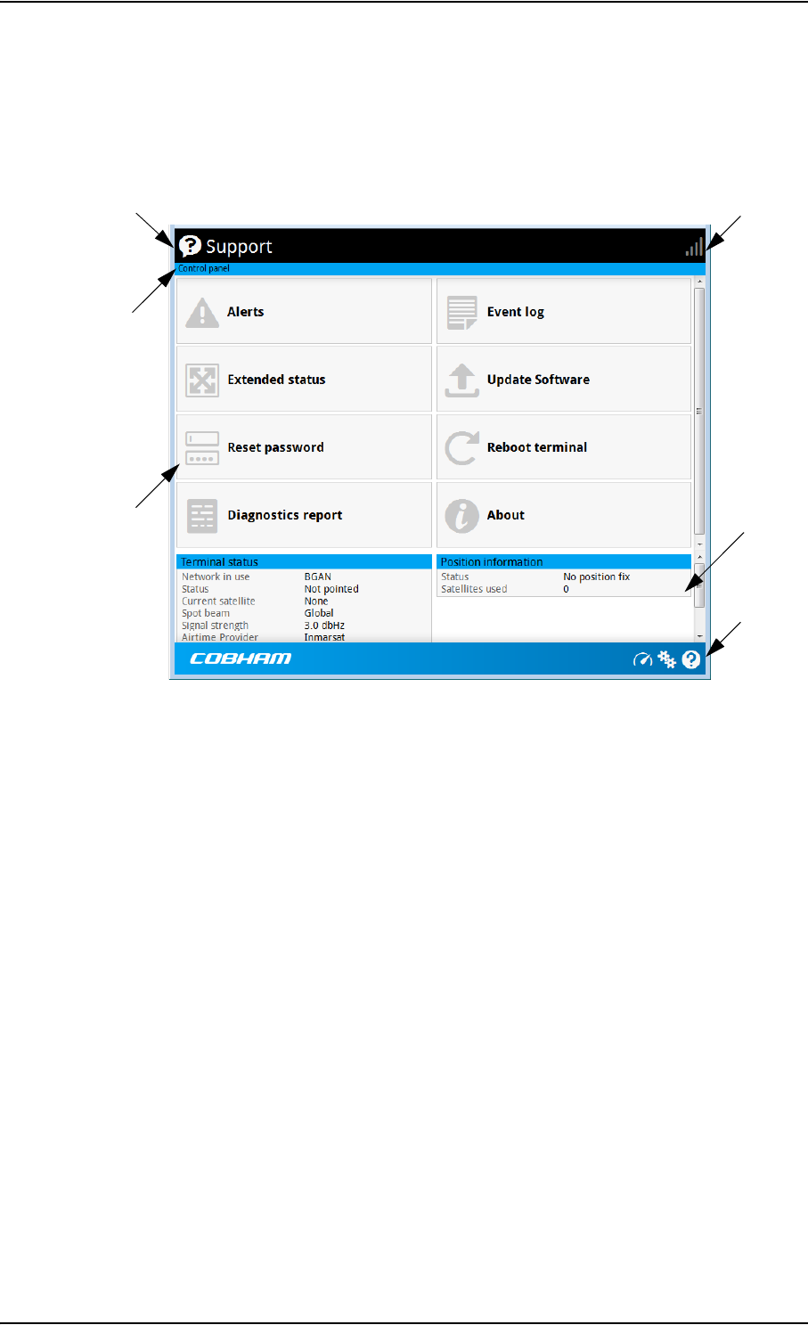
Chapter 4: Configuration with web interface
98-148232-B The web interface 40
Overview of the web interface
When the web interface opens, the title bar shows the name of the product. The example
below shows the Support page.
The web interface consists of the following sections.
•Name of current page. Tap or click to refresh the page.
•Icon bars at the top and bottom are present on all pages and hold icons that give access
to status such as signal level as well as active alerts, when relevant. It also holds the icon for
the Control panel. For explanations of the icons, see the next section, Icons in the icon
bars.
•Breadcrumbs right below the icon bar show the current location in the menu system and
gives access to the higher levels in the menu.
•Contents section shows the contents of the selected page. This section is used for
viewing or changing settings, or for performing actions. On the opening page, this section
is used to start and stop data connections.
•Status section shows the status of the terminal and the network connection, position
information, ongoing calls and data sessions etc. The Status section is not shown on small
screens. If the screen is small (e.g. on a smartphone), you can show/hide the status by
clicking at the bottom of the page.
Icon bar
Breadcrumbs
Name and icon of current page (on opening page: the name of the product)
Status
section
Icon bar
Contents
section

Chapter 4: Configuration with web interface
98-148232-B The web interface 41
Icons in the icon bars
The icon bars are always available at the top and bottom of the web interface. Some of the
icons are permanent while others are temporary.
To navigate the web interface
•To access status and settings, tap or click the relevant icon in the icon bar or select
to access the Control panel. The status or settings are displayed in the contents section.
•To see your current location and to move back through the Control Panel
menu, use the breadcrumbs just below the icon bar.
•To scroll through longer pages, use the scroll bar or swipe.
•To refresh the current page, press Ctrl+F5 (PC) or Apple+R (Apple) or Cmd+R (Apple).
Icon Explanation
Signal level of the external network.
Help. Click to get context-sensitive help for the current page.
Control panel. Click to access the settings.
Startup page where you can start and stop data connections.
Click to go to the startup page.
The “1” at the icon shows that a BGAN data connection
package is running.
Status. If the screen is not large enough to show the status
field, this icon appears at the bottom of the page. Click the
icon to see status of the terminal and satellite connection.
Click again to exit the status page.
An alert is active.
Click the icon to see a list of active alerts.
Note that this icon will remain in the icon bar as long as the
alert is still active.
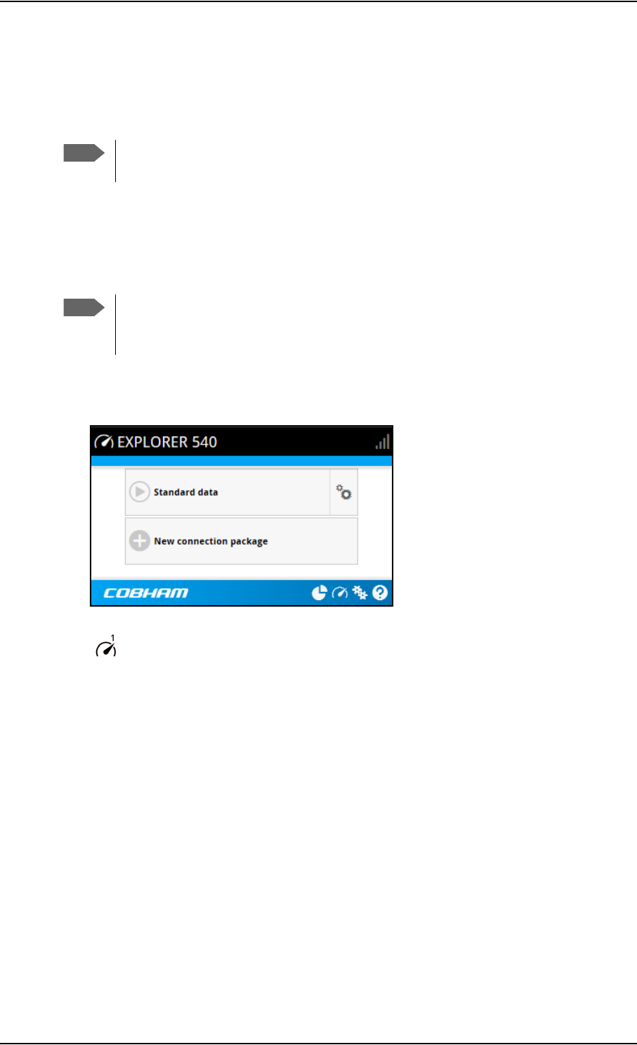
Chapter 4: Configuration with web interface
98-148232-B To control data connections from web interface 42
To control data connections from web interface
The startup page of the web interface is used to start and stop data connections and to set up
the data connections.
To start and stop data connections
By default, you must activate your data connection before you can access the Internet.
However, you can enable automatic activation of a data connection. See step 3. on page 51.
To start and stop data connections on your EXPLORER 540, do as follows:
1. In the opening page, locate the connection package you want to start.
2. Click to start the connection. The connections icon at the bottom of the page shows
when a BGAN data connection package is running.
3. Click to stop the connection.
If the connection fails, the connection tile shows an exclamation mark and an error
message. The error message is also shown in the data log, see Data log on page 48.
When a connection is active, the icon changes to and the tile for the active connection
shows:
• IP address: The external IP address that has been assigned by the service provider to this
session. If the connection was started by remote SMS, the local IP address is also shown.
• Transferred data: For Standard data, the tile shows the total amount of transmitted and
received data since the connection was established.
Note
With a non-M2M subscription you have more options for the data connection. See
Appendix C, BGAN non-M2M functions.
Note
The icons for starting and stopping connections are only active if the terminal
is ready and registered on the BGAN network. Otherwise the text is greyed out and
you cannot start data connections.
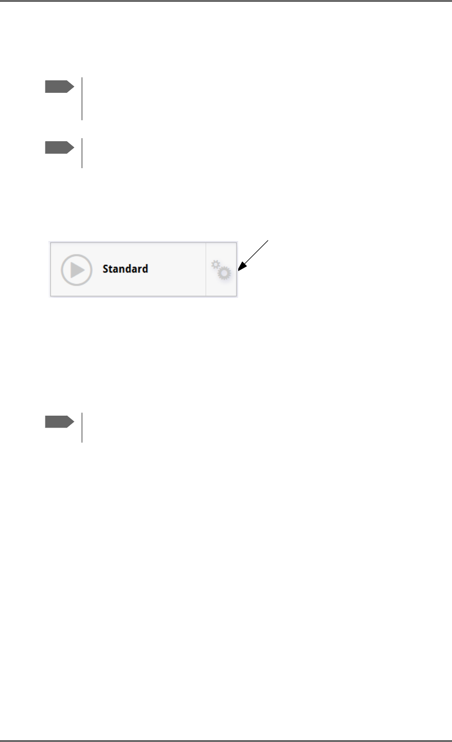
Chapter 4: Configuration with web interface
98-148232-B To set up your data connection packages (BGAN M2M) 43
To set up your data connection packages (BGAN M2M)
To change the name of a connection package
To change the name of a connection package, click in the right side of the tile with the
connection package.
Click Properties, type in the new name and click Save. The new name is shown on the tile on
the startup page.
To change the APN for a connection package
By default a connection package is set to use no IP Header compression and to use the APN
(Access Point Name) from the SIM card. This is suitable for most applications.
If you want to use a different APN, do as follows:
1. Click in the right side of the tile with the connection package that you want to change.
2. Select Parameters.
3. Next to APN, select the source of the APN.
•SIM default (default and recommended setting): The APN is taken from the SIM card.
•Network assigned: The APN is assigned from the network.
•User defined: APNs are provided from the Airtime Provider. Type in the APN next to
User defined name.
4. If your APN uses a password, type in the User name and Password provided from the
Airtime Provider.
5. Click Save.
Note
This section only describes the Standard data connection available with M2M
subscriptions. For information on class 2 subscription, see To set up data connections
on page 110.
Note
You must be logged in as administrator to be able to change the settings for a data
package.
Note
It is recommended to leave IP Header compression disabled. This means that the
data packets are transmitted more reliably with less data loss.
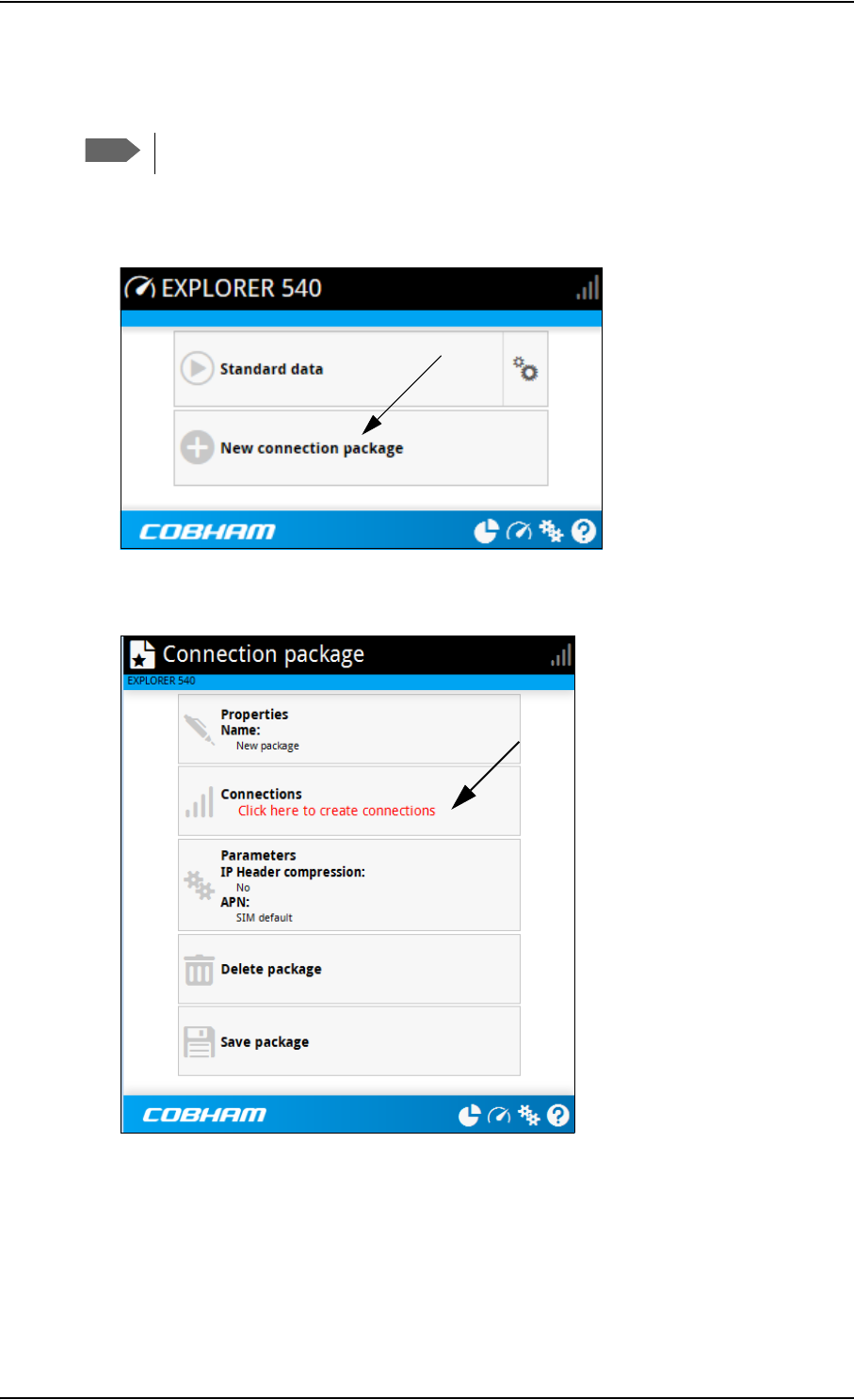
Chapter 4: Configuration with web interface
98-148232-B To set up your data connection packages (BGAN M2M) 44
To create a new connection package
Do as follows:
1. Click New connection package.
2. Type a name for the new package and click Save.
3. Click Click here to create connections.
4. Select the connection type you want for your new connection package.
For M2M subscription, you can only select Standard.
5. Click Save package.
The new package should now appear as a new tile on the startup page. For details on
Parameters (APN and IP Header compression) see To change the APN for a connection
package on page 43.
Note
You must be logged in as administrator to be able to create connection packages.
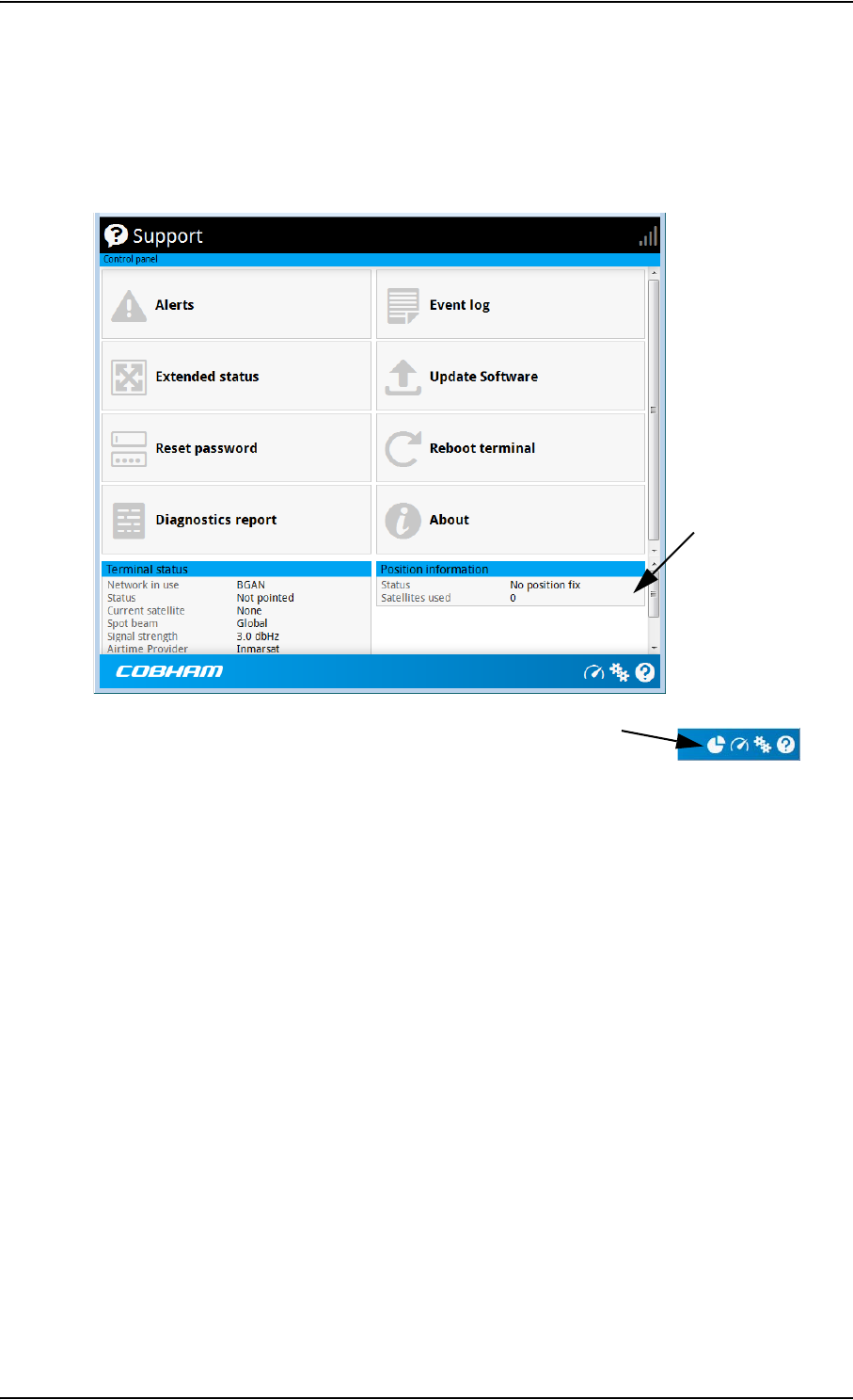
Chapter 4: Configuration with web interface
98-148232-B Status information 45
Status information
If the window is large enough, it shows a status field at the bottom of the page or in the right
side of the page. If not, click at the bottom of the page to show the status page. Click
again to return to the previous page.
Small screen: Click here for status page
Status field
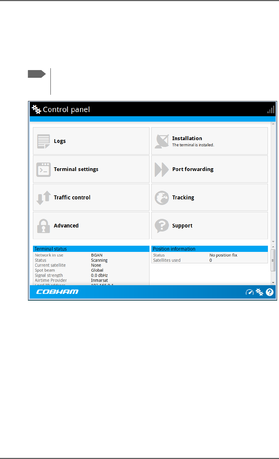
Chapter 4: Configuration with web interface
98-148232-B The Control panel 46
The Control panel
The Control panel is used for accessing the settings and functions of your EXPLORER 540.
To open the Control panel, click from the bottom right corner of the web interface.
Note
IP handsets: The M2M subscription does not support Voice over IP (VoIP). For details
on VoIP and voice calls with standard class 2 subscription, see Appendix C, BGAN
non-M2M functions.
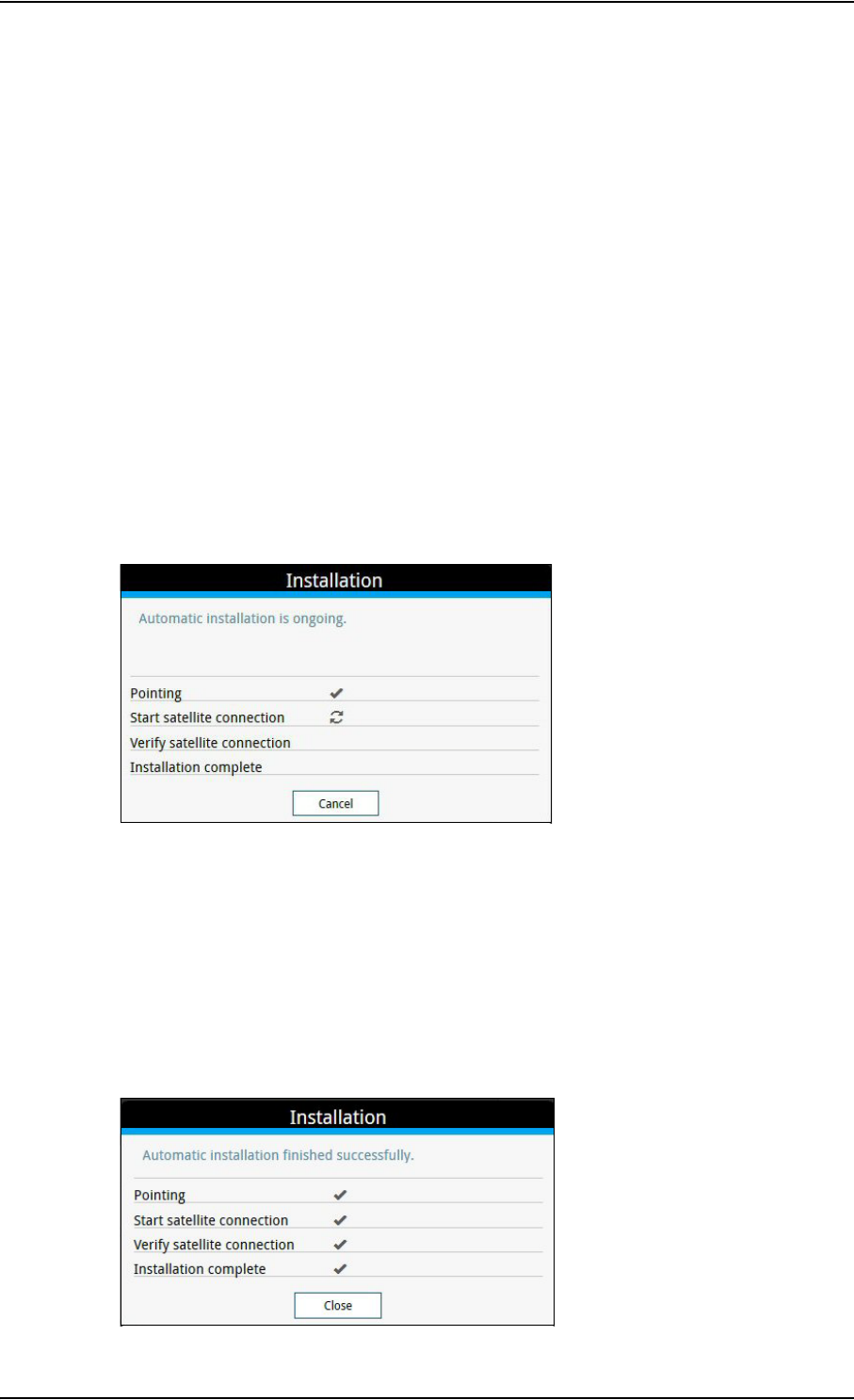
Chapter 4: Configuration with web interface
98-148232-B To restart the installation process 47
To restart the installation process
If you need to restart the installation process, e.g. because the EXPLORER 540 has been moved
to another location, click the Installation tile in the Control panel. This will reboot the
terminal and restart the installation process. For details about the installation process, see
Installation process on page 11.
To start the installation process from the web interface, do as follows:
1. Select (Control panel) and then Installation.
2. Select OK to reboot the terminal and start the installation process. Note that you must log
into the web interface with user name and password after reboot.
The signal strength is shown on the screen during the pointing process.
3. Turn and tilt the antenna slowly until you have obtained the highest possible signal
strength. You can use the pointing sound as well as the signal strength shown on screen.
For details, see Installation process for satellite operation on page 12.
4. When the EXPLORER 540 has detected a stable BGAN signal it automatically exits the
pointing process and starts to connect to the BGAN network.
• If you do nothing, the EXPLORER 540 automatically connects to the BGAN network (if
possible) and then completes the installation process.
• If you want to cancel installation and start over at next power-up, click Cancel. You can
still configure the EXPLORER 540, and the LED will be active.
If there are problems with the installation, the web interface will show a warning icon next
to the failing step in the installation window. The LED on the EXPLORER 540 will be yellow
(warning). See Troubleshooting guide on page 78.
5. Tighten the screws to fix the EXPLORER 540 in the pointed position.
6. When the installation process has ended, click Close to close the Installation window.

Chapter 4: Configuration with web interface
98-148232-B To use the logs 48
To use the logs
To access the logs
To access the Logs, select and select Logs from the menu. The Logs page contains:
•Call log: A list of all incoming, outgoing and missed calls since the log was last cleared.
•Data log: A list of all data sessions since the log was last cleared.
•Total counters: Totals for each type of service since the log was last cleared.
Date and time is the international UTC time, received from the satellite.
Call log (Non-M2M only)
With Non-M2M subscription the Call log shows:
•Outgoing calls shows the start time, receiving end phone number, duration, type
(Standard voice or 3.1 kHz audio), termination cause and, if Call charges have been
entered, estimated charge of each outgoing call.
•Received calls shows the start time, calling phone number, duration, type (Standard
voice or 3.1 kHz audio) and termination cause of each incoming call.
•Missed calls shows the start time, calling phone number, type (Standard voice or
3.1 kHz audio) and termination cause of each incoming call that was not received.
To clear the Call log, click the Clear call log button at the top.
Data log
The Data log shows:
•Standard data shows data usage, date and time, termination cause and estimated charge
of each Standard data session (if Call charges have been entered).
•For Non-M2M only: Streaming data shows the duration and type (such as 64 kbps,
128 kbps), date and time, termination cause and estimated charge of each Streaming data
session (if Call charges have been entered).
To clear the Data log, click the Clear data log button at the top.
Total counters
The total counters show:
•For Non-M2M only: Call session totals shows the total duration (hh:mm:ss) for each
call type since the log was last cleared. It also shows the estimated call charge for each call
type (if Call charges have been entered).
•Data session totals shows totals for each data connection type since the log was last
cleared. For Standard data the totals are shown as amount of data transferred (kB) and for
Streaming connections the totals are shown in duration (hh:mm:ss). It also shows the
estimated charge for each data type (if Call charges have been entered).
To reset the Total counters, click the Reset total counters button at the top.
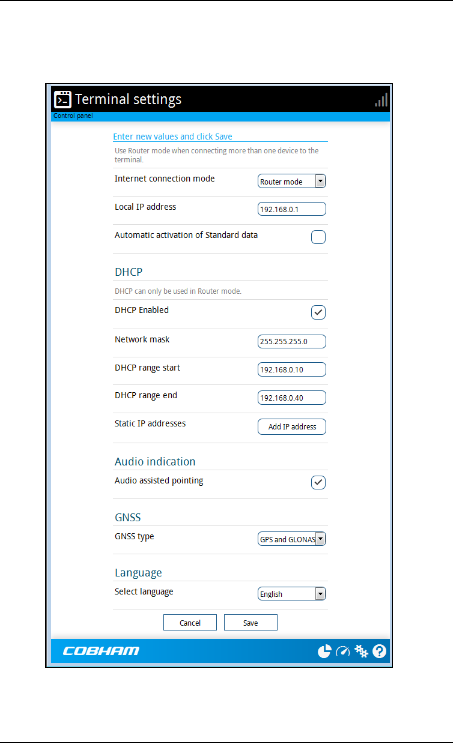
Chapter 4: Configuration with web interface
98-148232-B Terminal settings 49
Terminal settings
To configure the terminal settings, select (Control panel) > Terminal settings.
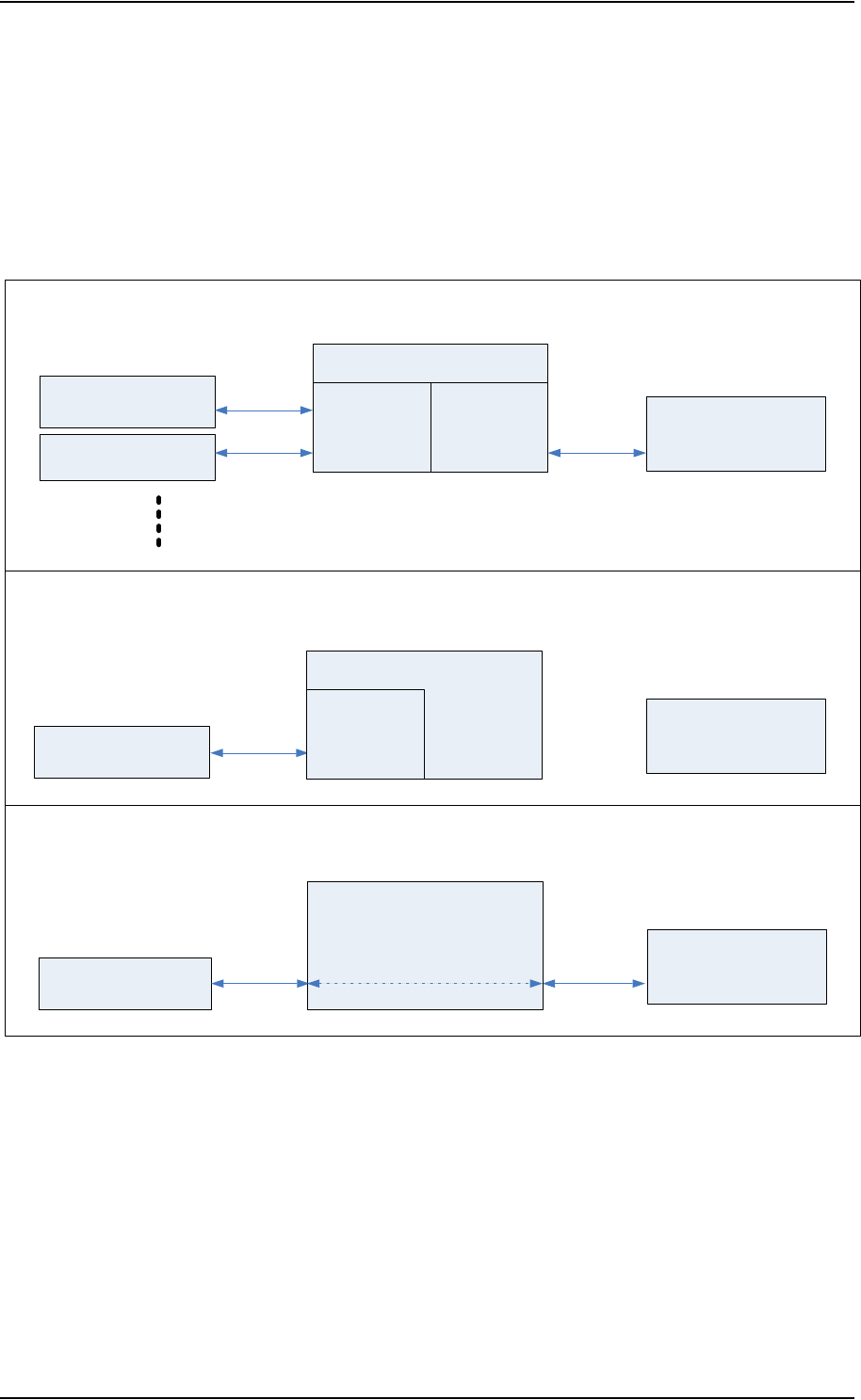
Chapter 4: Configuration with web interface
98-148232-B Terminal settings 50
To set up the connection mode
In the web interface you can set up the Internet connection mode and the IP addressing
between the EXPLORER 540 and devices connected to the EXPLORER 540. The EXPLORER 540
has a built-in DHCP server which can be used to dynamically assign IP addresses to devices
connected to the EXPLORER 540.
The drawing below shows examples of the IP addressing in router mode (default setup) and
modem mode.
5RXWHUPRGH
'HIDXOWVHWXSH[DPSOH
7HUPLQDO
'HYLFH
'HYLFH
Q
DVVLJQHGE\WKH
WHUPLQDOYLD'+&3
P
DVVLJQHGE\WKH
WHUPLQDOYLD'+&3
%*$1QHWZRUN
'+&3VHUYHU
DVVLJQHGE\WKH%*$1
QHWZRUNYLD'+&3
0RGHPPRGHZLWKDFWLYHFRQQHFWLRQWRWKH%*$1QHWZRUN
([DPSOH
'HYLFH
7HUPLQDO
,3DGGUHVVWRDFFHVVWKHWHUPLQDO¶VZHELQWHUIDFH
P
DVVLJQHGE\WKH%*$1
QHWZRUNYLD'+&3
Q
1$7'+&3
%*$1QHWZRUN
'+&3VHUYHU
Q
0RGHPPRGHQRFRQQHFWLRQWRWKH%*$1QHWZRUN
([DPSOH
7HUPLQDO
%*$1QHWZRUN
'+&3VHUYHU
Q
'HYLFH
/RFDO,3DGGUHVV
'+&3
Q
DVVLJQHGE\WKH
WHUPLQDOYLD'+&3

Chapter 4: Configuration with web interface
98-148232-B Terminal settings 51
To set up the connection mode of the EXPLORER 540, do as follows:
1. At Internet connection mode, select Modem mode or Router mode. Router mode
is the default setting and is recommended for most purposes.
• Select Router mode if one or more computers are connected and the EXPLORER 540
should act as a router. When Router mode is selected, the EXPLORER 540 uses the built-
in NAT module for making the necessary address translations.
• Select Modem mode if only one computer is connected, and the EXPLORER 540
should act as a modem, or more than one computer is connected using an external
router.
2. Under Local IP address, type in a new IP address if you want to change the Local IP
address of the terminal. This is the address used to access the web interface. The default IP
address is 192.168.0.1.
3. To enable automatic activation of your data connection, select Automatic activation of
Standard data.
•When you select automatic activation, the data connection is automatically
established after restart as soon as the EXPLORER 540 and its BGAN connection are
ready.
•When you disable automatic activation (default), you can control the data connection
manually from the startup page or with the SMS command ACTIVATE.
4. Under DHCP, select DHCP Enabled (recommended for most purposes).
•If you select DHCP Enabled, the terminal assigns dynamic IP addresses to devices
connected to the terminal.
•If you select disable DHCP, you need to set up a static IP address in the connected
device.
5. If you want to change the Network mask for the local network of the terminal, type in
the new network mask. The default network mask is 255.255.255.0.
6. Under DHCP range start and DHCP range end, type in the range of IP addresses that
should be assigned to locally connected equipment.
7. Under Static IP addresses add any static IP addresses used by locally connected
equipment. This is necessary in order to be able to access the equipment remotely.
8. Click Save.
Note
Do not connect more than one computer in Modem mode, unless you have an
external router.
Important
Do not use any of the reserved IP addresses listed in List of reserved IP
subnets on page 88.
Note
You are charged for the data transferred. You may want to disable automatic
updates in your LAN device to avoid unnecessary charges.
Note
The static IP addresses must be outside the DHCP range set in the previous step.

Chapter 4: Configuration with web interface
98-148232-B Terminal settings 52
To enable or disable the pointing sound
The EXPLORER 540 can make a sound to guide you through the pointing procedure (default
enabled). To enable or disable the pointing sound, do as follows:
1. In the Terminal settings page, locate the Audio indication section.
2. Select Audio assisted pointing if you want to use a pointing sound to assist your
pointing process.
3. Click Save.
To select the type of navigation system (GNSS)
To select which navigation system to use with your EXPLORER 540, do as follows:
1. In the Terminal settings page, locate the GNSS section (Global Navigation Satellite
System).
2. Select GPS, GLONASS, GPS and GLONASS or BeiDou-1.
3. Click Save. Note that it may take some minutes for the EXPLORER 540 to change the
navigation system.
To select the language
The default language of the web interface is English. You can change the language to French,
German, Russian, Spanish, Chinese or Japanese.
To change the language, do as follows:
1. In the Terminal settings page, locate the Language section.
2. Select a language from the list and click Save.

Chapter 4: Configuration with web interface
98-148232-B Port forwarding 53
Port forwarding
Port forwarding enables you to set up a server connected to the terminal while the terminal is
in Router mode. Without port forwarding it would not be possible to contact the server from
the Internet. We recommend using a static public IP address for the terminal in order to
provide easy access to the terminal. To use the static IP address, it must be included in your
subscription and you must set the APN source to SIM default. For details, see To change the
APN for a connection package on page 43.
Do as follows:
1. From the Control panel , select Port forwarding.
2. Select Forward port to add a new port forwarding.
3. Select Active to activate the port forwarding.
4. Type in the Incoming port start and the Incoming port end.
This is the range of port numbers on the EXPLORER 540 for which incoming traffic to the
EXPLORER 540 will be forwarded.
5. Type in the Destination IP address, which in this example is the IP address of the mail
server: 192.168.0.100.
This is the IP address to which the incoming traffic is forwarded.
6. Type in the Destination port start and the Destination port end.
This is the range of port numbers at the server, to which the incoming traffic will be
forwarded. If only a single port is used, type the same port for Destination port start
and Destination port end.
7. Click Save.
When you have activated a data connection, you can now access the server from the Internet,
using the external IP address of the terminal. If you are using the web interface, you can see
the external IP address in the tile with the data connection you have started. For information
on how to activate your data connection, see To control data connections (PDP contexts) on
page 29.
Note
Make the port forwarding configuration before starting the data session.
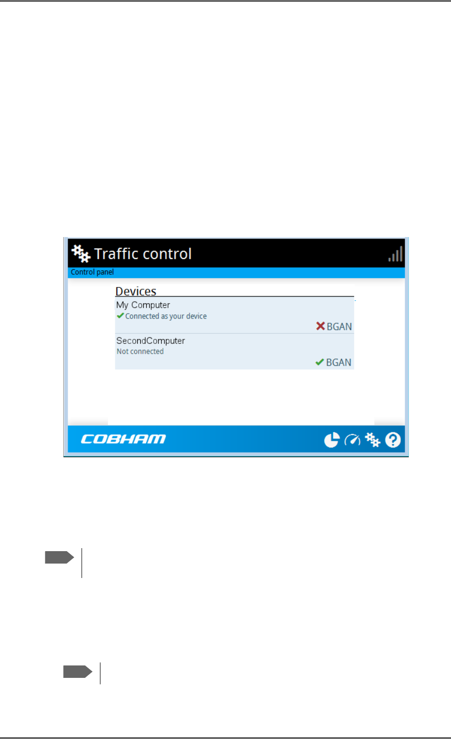
Chapter 4: Configuration with web interface
98-148232-B To manage connected devices (Traffic control) 54
To manage connected devices (Traffic control)
By default, traffic control is disabled, which means that all traffic is allowed.
With the Traffic control function you can get an overview of devices connected locally to your
EXPLORER 540 and control which devices you want to connect. You can also select whether or
not they should be allowed to use the BGAN network. Note that the available settings depend
on whether or not you are logged in as administrator.
Traffic control (Non-administrator user)
To set up traffic control, do as follows:
1. In the Control panel , click Traffic control.
A list of connected and added devices appears.
2. Click your connected device to see MAC address and IP address and to change the name
or block/allow the use of BGAN network. See the next section.
To block BGAN traffic or edit the name for your device
1. In the Traffic control page, click your connected device.
The page shows the name, MAC address, IP address and traffic rule for the device.
2. Select Block BGAN traffic, if you want to deny access to the BGAN network for your
device.
Note
You can only change these settings if traffic control is enabled. If the administrator
has disabled traffic control, all traffic is allowed.
Note
If it is already blocked by the administrator, this setting is not editable.
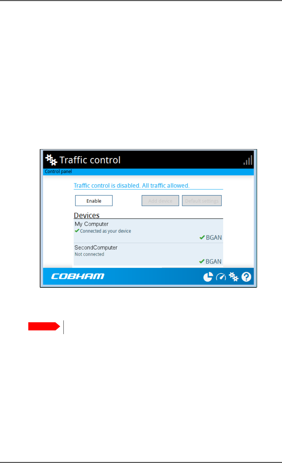
Chapter 4: Configuration with web interface
98-148232-B To manage connected devices (Traffic control) 55
3. At Name, type in the name you want for your device.
4. Click Save.
Traffic control (administrator)
When you are logged in as administrator, the Traffic control setup offers more options. To set
up traffic control as administrator, do as follows:
1. Log in as administrator.
2. In the Control panel , click Traffic control.
A list of connected and added devices appears.
3. Click the Enable button to enable Traffic control.
By default Traffic control is disabled, which means all devices are allowed access.
To change the default settings for all devices
1. Click the button Default settings.
2. Select Block BGAN traffic if you want to deny access to BGAN network for all devices.
With this option selected, only the administrator will be able to allow access for selected or
all devices.
3. Click Save.
All devices in the list will now have the new default settings.
Important
All devices in the list are updated with the default settings when you click Save.

Chapter 4: Configuration with web interface
98-148232-B To manage connected devices (Traffic control) 56
To block or allow BGAN traffic or edit the name for a device
1. In the Traffic control page, click the device you want to set up.
The page shows the name, MAC address, IP address and traffic rule for the device.
2. Select Block BGAN traffic, if you want to deny access to the BGAN network for the
selected device.
If you want to allow access, clear the box. The selected device will then be able to access
the network, even if it is blocked in the default settings (see previous section).
3. At Name, type in the name you want for your device.
4. Click Save.
To Add a device
When you connect a device, it is automatically added to the list using the default settings. If
you want to add a device for later use, do as follows:
1. In the Devices page, click the Add device button.
2. Type in the Name and the MAC address for the device.
3. Select Block BGAN traffic, if you want to deny access to BGAN network for the selected
device.
If you want to allow access, clear the box. The selected device will then be able to access
the network, even if it is blocked in the default settings (see previous section).
4. Click Save.
When the device with this MAC address is connected, it will appear with the entered name in
the list, and access will be allowed or denied depending on the setting in this page.
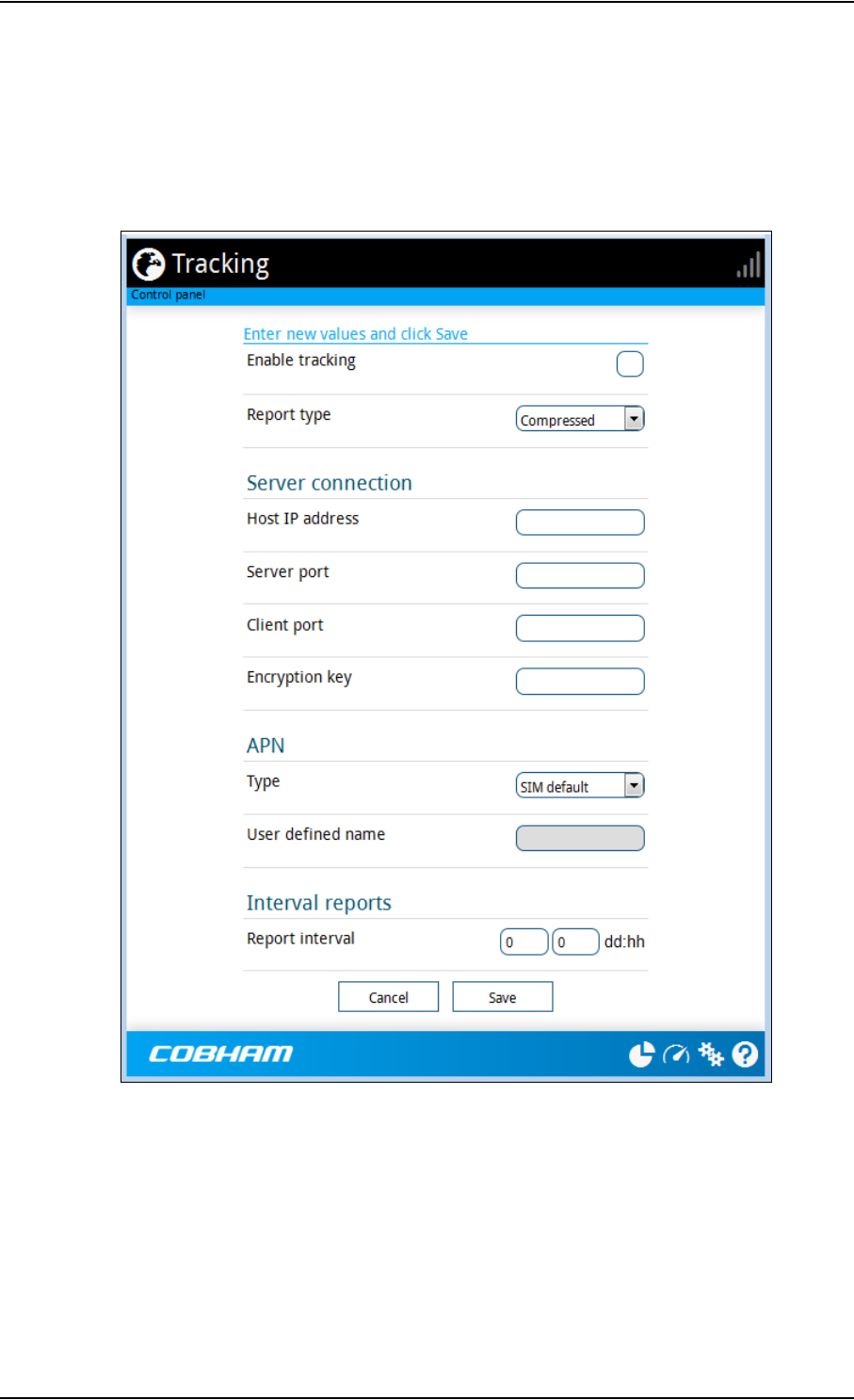
Chapter 4: Configuration with web interface
98-148232-B To set up tracking 57
To set up tracking
You can set up the EXPLORER 540 to report to a server at certain time intervals. To set up
tracking, do as follows:
1. From the Control panel , select Tracking.
2. To enable tracking of the EXPLORER 540, select Enable tracking.
3. Select the Report type.
•Compressed. Only latitude and longitude are reported.
•Extended. Apart from latitude and longitude, heading and altitude are also included.
•ECEF. The same information as Extended, but position and speed data are 3D (ECEF
coordinates).
4. Under Server connection, type in the following details:

Chapter 4: Configuration with web interface
98-148232-B To set up tracking 58
•Host: The IP address of the server that the EXPLORER 540 will report to.
•Server port: Port number on the server. Default number is 7474.
•Client port: Port number on the EXPLORER 540. Default number is 7475.
•Encryption key: A 128 bit key which must match on both the client and server side.
Supplied from the server manager.
5. Under APN, select the source of the APN.
•SIM default (recommended): The APN is taken from the SIM card.
•Network assigned: The APN is assigned from the network.
•User defined: APNs are provided from the Airtime Provider. Type in the APN next to
User defined name.
6. Type in the Report interval in days (dd) and hours (hh).
Example: If you type in “01” and “12”, the EXPLORER 540 will send a report for every 1½
day.
7. Click Save.
You can see the status of the tracking link in the status area of the web interface. If the status
area is not shown, click to see it.
Note
If the EXPLORER 540 is in power save mode, no report is sent!
Note
You can set up whether or not you want to allow the tracking server to control these
settings. See Remote control of tracking on page 70.
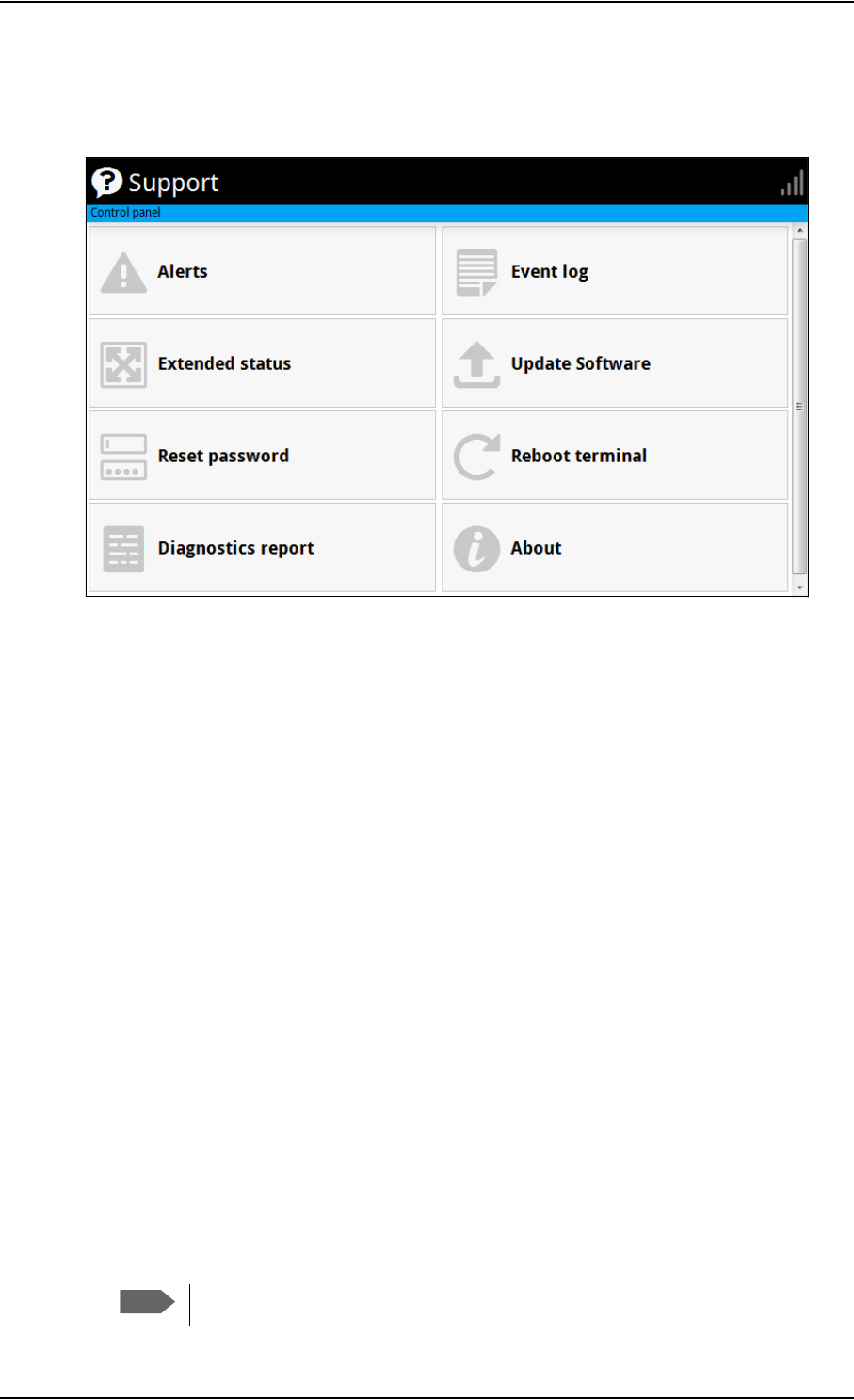
Chapter 4: Configuration with web interface
98-148232-B Support features 59
Support features
To open the Support page, select (Control panel) > Support.
To view the Alerts
When an alert is registered, the web interface shows a warning icon in the icon bar as long
as the alert is active. The Alerts list only shows alerts that are currently active.
1. To view the alerts, click from the icon bar at the top of the web interface, or select
Alerts from the Support page.
The Alerts page shows a list of active events. For more information on the event messages,
refer to List of messages on page 82.
To view the Event log
The Event log shows events that occurred in the past and are no longer active. It includes
events of informational character describing normal phases of operation for the terminal, and
also alerts that have appeared in the Alerts list.
To view the event log, select Event log from the Support page.
To create a diagnostics report
The diagnostic report contains relevant information for troubleshooting. When contacting
your supplier for support, please enclose this file. To generate a diagnostic report, do as follows:
1. From the Support page, click Diagnostics report.
2. Click Generate report.
Note
It may take a few minutes to generate the report.

Chapter 4: Configuration with web interface
98-148232-B Support features 60
3. Select Download report.
4. Choose a location for the file and save it.
To update software
To update the software in the EXPLORER 540 using the web interface, do as follows:
1. Download the new software1 or acquire the software from Cobham SATCOM and save it
on your computer.
2. Open the web interface and enter the Control panel .
3. Click Support > Update software.
4. Click Update software...
5. Browse to the new software version and click Open. The software file has the extension
“.tiif”.
6. The terminal restarts and completes the software update.
You can check the software version under Control panel > Support > About.
To view extended status
To see the Extended status page, select Support > Extended status.
To view updated information on the Extended status page, click the icon in the top left
corner to refresh the page.
The Extended Status page shows information such as IAI-2 status, IMSI number and IMEI
number.
1. You can download the software from the “Self Service Centre” at www.cobham.com/satcom,
select Service and Support > Cobham SATCOM Service and Support and then 24-7 Self
Service Centre / Technical Downloads. Locate the EXPLORER 540 software.
Note
The update procedure takes some minutes to complete. If the installation
process has not yet been completed, the Status LED flashes blue during the
software update.

Chapter 4: Configuration with web interface
98-148232-B Support features 61
To reset the administrator password
If you have forgotten the administrator password, do as follows:
1. Contact your supplier for a reset code.
Report the serial number and IMEI number of the terminal.
You can find the serial number under Control panel > Support > About and the IMEI
number under Control panel > Support > Extended status.
2. After receiving the reset code from your supplier, select Reset password from the
Support page.
3. Type in the reset code obtained from your supplier and click Reset.
4. The password is reset to admin.
To restart the terminal
If you want to restart the terminal, do as follows:
1. From the Support page, select Reboot terminal.
2. Click to confirm the reboot.
The terminal restarts. Note that this is the equivalent to switching the terminal off and on
again. It is not the same as pushing the Reset button, the installation process will not
restart.
About
The About page shows the Serial number and software version of your EXPLORER 540
and legal information. It also shows your Help desk information, if it has been entered under
Advanced > Help desk.
To access the About page, select Support > About.
Note
If you have physical access to the EXPLORER 540, you can also use the Reset button.
For details, see Reset button on page 77.

Chapter 4: Configuration with web interface
98-148232-B Advanced settings 62
Advanced settings
Passwords
The EXPLORER 540 web interface is password protected at two levels: A user password and an
administrator password. You will always be prompted for a password when you access the web
interface.
Default settings are:
•User: User name: user, Password: <serial number of the EXPLORER 540>
•Administrator: User name: administrator, Password: admin
You can change the passwords if you are logged in as administrator, see the next sections.
To log in as administrator
Access to the Advanced settings requires an administrator password. If you are already logged
in as user and you want to access the Advanced settings, do as follows:
1. From the Control panel , select Advanced.
If you are not logged in as administrator you are now prompted to log in.
2. Enter the administrator password.
If you have forgotten the administrator password, you can reset the password. For details,
see To reset the administrator password on page 61. The old user name and password will
apply until you have finished the reset procedure.
3. Click Login.
To change the user password
To change the user password, do as follows:
1. Log in as administrator
2. Under Advanced, select Change user password.
3. Type in the Old password.
4. Type in the New password and retype it on the next line.
5. Click Save.
At the next login the new password is required.
To change the administrator password
To change the administrator password, do as follows:
1. Log in as administrator
2. Under Advanced, select Change admin password.

Chapter 4: Configuration with web interface
98-148232-B Advanced settings 63
3. Type in the Old password.
4. Type in the New password and retype it on the next line.
5. Click Save.
At the next login the new password is required.
To log out as administrator
If you close the web interface, you are logged out automatically after 30 seconds. To log out
manually, click Logout administrator in the Advanced page.
To set up user permissions
You can allow or deny users access to certain functions and make these pages read-only. This is
useful if you want to protect the system against unintended changes. Study this screen
thoroughly and decide to which areas of the system you want to give non-administrator users
access. To set up the user permissions, do as follows:
1. Under Advanced, select User permissions.
2. Under Allow users to:, select the settings you want to allow users to access.
3. Under Allow AT commands on:, select LAN interface if you want to allow the use of
AT commands.
4. Under Allow user accounts:, select Service user account if you want to enable the
use of a service user account.
5. Click Save.
The settings without a check mark can only be viewed but not changed by the non-
administrator user.
To restore factory settings
To restore the factory settings of the EXPLORER 540, do as follows:
1. Under Advanced, select Factory reset.
2. Click OK.
The terminal will now restart and start up with the factory settings. The installation process
is also restarted.
Important
All configuration will be lost and the EXPLORER 540 will return to the default
configuration.

Chapter 4: Configuration with web interface
98-148232-B Advanced settings 64
SIM PIN for BGAN
To enable or disable the use of a SIM PIN
To enable or disable the use of a PIN to access the BGAN network, do as follows:
1. Under Advanced, select SIM.
2. Select Enable/disable SIM PIN.
3. Under Enable/Disable PIN select or clear the box next to Require PIN on startup.
• If you clear the box, you can access and use the terminal without entering a PIN
• If you select the box, you must enter a PIN on startup before you can make calls or data
sessions
4. If you selected Require PIN on startup, type in the PIN next to Enter current PIN.
5. Click Save.
The new PIN settings will take effect at next power on.
To change the SIM PIN
To change the PIN used to access the BGAN network, do as follows:
1. Under Advanced, select SIM.
2. Select Change SIM PIN.
3. Under Change PIN type in the Current PIN.
4. Type in the New PIN and retype it on the next line.
5. Click Save. The new PIN settings will take effect at next power on.
Auto SIM PIN validation
The Auto SIM PIN validation feature allows the EXPLORER 540 to automatically send the PIN
to the SIM at power up. This enables the SIM to be PIN locked (to prevent unauthorised re-use
of the SIM elsewhere), while still allowing the EXPLORER 540 to connect to the BGAN network
without using a PIN.
When this feature is enabled, the PIN you enter when setting the Auto SIM PIN validation
feature is encrypted and stored locally in the EXPLORER 540. The next time the EXPLORER 540
restarts, the terminal decrypts the PIN and automatically sends it to the SIM without user
intervention.
To set up the Auto SIM PIN validation feature, do as follows:
1. Under Advanced, select SIM.
Note
The SIM PIN must be enabled before you can use this feature. See To enable or
disable the use of a SIM PIN on page 64.

Chapter 4: Configuration with web interface
98-148232-B Advanced settings 65
2. Select Auto SIM PIN validation.
3. Select Automatically validate SIM PIN on startup.
4. Enter the PIN.
5. Click Save.
SIM lock
The SIM lock feature can be used by suppliers to lock your SIM card to a specific provider or
distribution partner. For further information, contact your supplier.
To save or load a configuration
If you need to reuse a configuration in other terminals of the same type, you can save your
current configuration to a file, which can then be loaded into the other terminal(s).
To save a configuration to a file
To save the current configuration of your EXPLORER 540 to a file on your computer, do as
follows:
1. In the Advanced page, click Load/save configuration.
2. Click Save configuration.
The configuration file is saved in the EXPLORER 540.
3. Click Download configuration...
The configuration is downloaded from the EXPLORER 540 to the downloads section of
your computer.
To load a configuration from a file
To load a configuration from a file into your EXPLORER 540, do as follows:
1. In the Advanced page, click Load/save configuration.
2. Click Load configuration.
Note
If the SIM PIN is changed either using the web interface or AT commands, the Auto
SIM PIN validation feature is disabled and must be reenabled manually.
Note
If the SIM card is replaced without disabling the Auto SIM PIN validation feature, and
the first verification of the SIM PIN fails, the Auto SIM PIN validation feature will
disable itself to avoid locking the SIM card.
Note
Be aware that if the terminals have different software versions, some of the settings
may be different than expected. If possible, use the same software version in the
terminals.

Chapter 4: Configuration with web interface
98-148232-B Advanced settings 66
3. Browse to the configuration file and click Open...
The configuration is now loaded into your EXPLORER 540. When the configuration is loaded
successfully, the EXPLORER 540 restarts with the new configuration.
Link monitoring
It is strongly recommended to use link monitoring to monitor your locally established IP
connection, as it enables you to test the BGAN connectivity and to keep your PDP context
alive.
With this feature activated, the terminal will send out ping commands to up to three servers of
your choice. When a data session is started, the terminal will start sending ping commands to
the Primary IP address the number of times specified. If no response is received, it will send the
same number of ping commands to the Secondary and then the Tertiary IP address, if
available. If no response is received from any of the IP addresses, the terminal will eventually
restart.
To set up link monitoring, do as follows:
1. Under Advanced, select Link monitoring.
2. Select Enable Link monitoring.
3. At Ping interval (minutes) select the Interval in minutes between the ping commands.
4. Select the Number of retries before the terminal restarts.
5. Select the Ping mode.
•Ping always: Always send ping, regardless of data traffic.
•Ping when no traffic: Send ping only if no data traffic is ongoing.
6. Type in the Primary and optionally the Secondary and Tertiary IP address.
This is the IP address of the server(s) to which the terminal will send ping commands.
7. Click Save.
Note
The data connection must be activated before link monitoring can start. See To start
and stop data connections on page 42.
Note
Use a server that is reliable and that responds to ICMP Echo Requests.

Chapter 4: Configuration with web interface
98-148232-B Advanced settings 67
Data limits
You can set a limit for the use of data services with the EXPLORER 540 system.
If you have entered the call charges in the menu Call charges, the system automatically
calculates and displays the estimated maximum charges for your data sessions.
Once the entered limit is reached, the connection is automatically stopped. This is recorded in
the data log. To continue using the data service you must start a new connection by clicking on
the desired connection on the startup page.
To set data limits, do as follows:
1. Under Advanced, select Data limits.
2. Select the type of connection you want to limit.
3. Type in the amount of data or time allowed and select the appropriate units.
4. Select Enable.
5. Click Save to save the settings.
Call charges
If you know the tariff for your subscribed services, you can enter these tariffs in the web
interface and automatically calculate the estimated charges for your calls and data sessions. To
enter the call tariffs, do as follows:
1. Under Advanced, select Call Charges.
2. Select the currency from the Displayed currency drop-down list.
3. Enter the tariff for each of the services.
4. Click Save.
The entered tariffs are used for estimating the charges for calls and data sessions. For
further information, see Call log (Non-M2M only) on page 48.
Note
Thrane & Thrane A/S does not take responsibility for the correctness of the estimated
charges. This calculation is only a rough estimate of the charge, based on the tariff
entered by the user. Also, the airtime provider may have different methods of
calculating the charge.
Note
If you have enabled automatic activation of the Standard data connection and you
set a data limit for the Standard data connection, automatic activation is disabled.
Note
Thrane & Thrane A/S does not take responsibility for the correctness of the estimated
charges. This calculation is only a rough estimate of the charge, based on the tariff
entered by the user. Also, the Airtime Provider may have different methods of
measuring the airtime used.
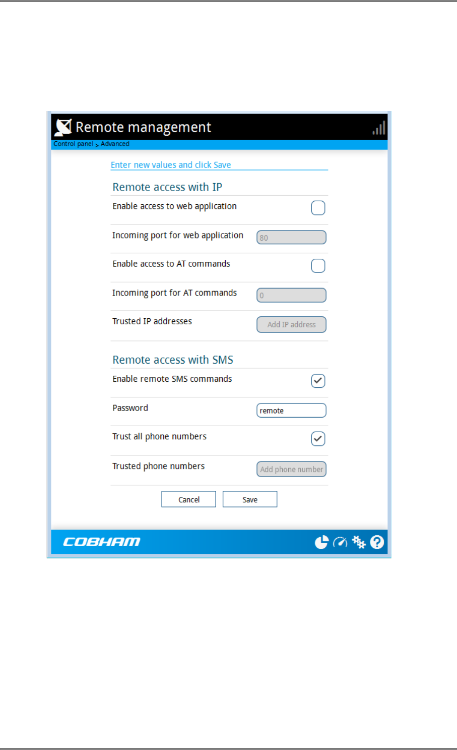
Chapter 4: Configuration with web interface
98-148232-B Advanced settings 68
Remote management
You can set up the terminal so that it can be controlled from a remote location.
To set up the terminal for remote management, select Advanced > Remote management
from the Control panel.

Chapter 4: Configuration with web interface
98-148232-B Advanced settings 69
To set up remote access with IP
1. From the Remote management page, select Enable access to web application and/
or Enable access to AT commands.
2. Type in the Incoming port numbers to use for the web server and for AT commands.
The default port numbers are:
•web server: 80
• AT commands: 5454
3. Under Trusted IP addresses, click Add IP address and type in the IP address of the
device you want to give access to the terminal.
4. To add more IP addresses, click Add IP address again.
After preparing the terminal and activating the connection you can access the terminal from
one of the trusted IP addresses, using the incoming port defined in the Incoming port field.
• For information on how to prepare the terminal for remote activation of a data
connection, see the next section To set up remote access with SMS.
• For information on how to access the terminal, see To access the terminal from a
remote location on page 20.
If Static IP is included in your airtime subscription, we recommend using this static public IP
address for the terminal in order to provide easy access to the terminal. To use the static IP
address, it must be included in your airtime subscription and you must set the APN source to
SIM default. For details, see To change the APN for a connection package on page 43.
To set up remote access with SMS
1. From the Remote management page, select whether you want to Enable remote
SMS commands.
2. Enter the password for remote SMS. It can be up to 32 characters long. The characters 0-9,
a-z and A-Z are allowed. The password is mandatory. This password must be entered
every time you send an SMS command. Default password is remote.
Note
The settings for Remote access with IP are not relevant if you are using the
_IREMWEB command. See To use AT commands to get remote access to the web
interface on page 25.
Note
If you type another port number, the port number must be available at your
service provider.
Note
To be able to access the terminal you must have an active data connection.
Note
The terminal must be registered to the satellite services to receive and accept an SMS.

Chapter 4: Configuration with web interface
98-148232-B Advanced settings 70
3. Clear the box Trust all phone numbers and enter at least one trusted mobile number
from which the terminal accepts an SMS. Use the wild card * to accept a range of trusted
numbers. Leave out the prefix before the country code (example: for “+45” write only “45”)
4. To add more phone numbers, click Add phone number again.
5. Click Save.
For information on how to send SMS commands, see Remote access with SMS on page 20.
Remote control of tracking
When you are using the tracking function of the EXPLORER 540, you can set up the terminal so
that the tracking server can access the EXPLORER 540 e.g. to start or stop tracking or to change
reporting intervals.
To allow the tracking server to control the tracking settings, do as follows:
1. Under Advanced, select Tracking settings.
2. Select Allow remote control of tracking.
3. Click Save.
The EXPLORER terminal will now accept commands from the specified tracking server, for
example to change reporting intervals or start/stop reporting.
Entered mobile number with wild card Mobile numbers accepted
453955880* +4539558800 to +4539558809
45395588* +4539558800 to +4539558899
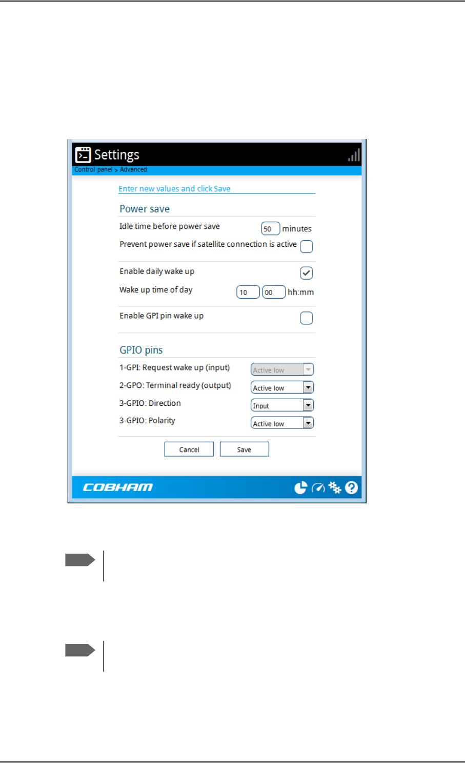
Chapter 4: Configuration with web interface
98-148232-B Advanced settings 71
Power save (Settings)
There are a number of options to save power in the EXPLORER 540. For a general description of
the power save options, see Power-saving on page 31.
To set up the power save options, do as follows:
1. Under Advanced, select Settings.
2. Select how many minutes with no (local) activity before the terminal should enter power
save mode (Idle time).
3. Select Prevent power save if satellite connection is active if you do not want the
terminal to enter power save mode when a data connection (PDP context) is opened on
the satellite connection.
4. Select Enable daily wake up and enter the Wake up time of day if you want the
terminal to “wake up” from power save mode at a specific time every day.
Note
If you select 0 (zero), the power save function is disabled and the terminal will
never enter power save mode.
Note
With this option selected, the terminal will not enter power save mode if there is
a PDP context open, even if it is not currently used to send or receive data.
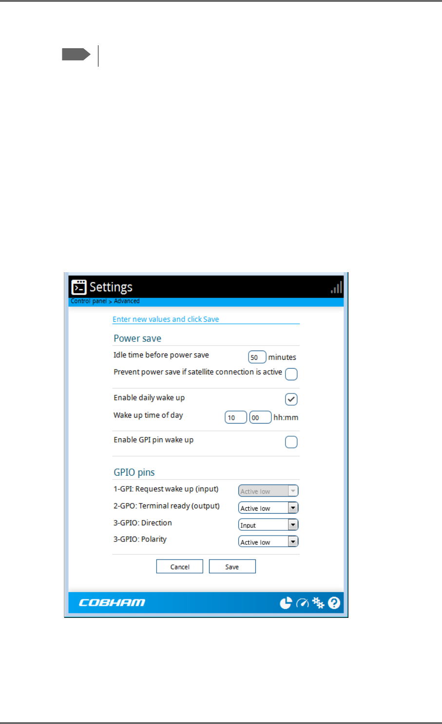
Chapter 4: Configuration with web interface
98-148232-B Advanced settings 72
5. Select Enable GPI pin wake up if you want to use the dedicated I/O pin on the
EXPLORER 540 to wake up the terminal from power save mode. See the next section I/O
pins (Settings) on page 72.
6. Click Save.
I/O pins (Settings)
The EXPLORER 540 has 3 I/O pins, two assigned pins and 1 general purpose pin.
• Request wake up (input)
• Terminal ready (output)
• Control/Status input/output
1. Under Advanced, select Settings.
2. If you have enabled GPI pin wake up, select whether the Request wake up input should be
active high or low.
3. Select whether the Terminal ready output should be active high or low. This output
signals when the EXPLORER 540 is ready to communicate with connected equipment.
Note
Local time must be converted to UTC time!

Chapter 4: Configuration with web interface
98-148232-B Advanced settings 73
4. If you want to use GPIO pin 3, select the direction and polarity.
Pin 3 does not have a predefined function, but can be used for remote control/status of
connected M2M equipment using AT command _ITGPIO. See Control or status with
GPIO pin 3 on page 37.
5. Click Save.
Help desk
Under Help desk you can enter the contact information you want for your EXPLORER 540. The
Help desk contact information is empty by default. You must provide the contact information,
e.g. the phone number for your Airtime Provider. Do as follows:
1. In the Advanced page, select Help desk.
2. Type in the contact information you want.
3. select Save.
The Help desk information is now available from (Control panel) > Support > About.
Reset button
You can change the function of the Reset button. See Reset button on page 77. Do as follows:
1. From the Advanced page, select Reset button.
2. Select the behavior you want for the Reset button.
•Enabled: Short push: The EXPLORER 540 restarts (power cycle) and begins the
installation process again., Long push: Reset to factory default.
•Long press disabled: The Reset button will not be able to reset to factory default, but
the short push function will still work.
•Disabled: The Reset button will not have any function.
3. Click Save.
Note
“Terminal ready” only signals that the terminal is awake and ready to
communicate with connected equipment. It does not show whether or not the
terminal is registered on the network, or a data connection is established. See
Power-saving on page 31 and Automatic Context Activation (ACA) on page 29.

Chapter 4: Configuration with web interface
98-148232-B To enter the SIM PIN in the web interface 74
To enter the SIM PIN in the web interface
Do you need a SIM PIN?
If a computer is connected when you start up the terminal, you can access the web interface
and enter the SIM PIN here.
To enter the SIM PIN
If your SIM card requires a PIN and the PIN has not yet been entered, you must enter it before
you can make calls or access the Internet. Until you have entered the PIN you cannot access
the network, but you can still configure your terminal.
To enter the PIN, do as follows:
1. Access the web interface.
If the terminal needs a PIN, a popup window tells you to enter PIN.
2. Type in your PIN and click OK.
When pointing is completed and the correct PIN is entered, you are ready to make calls or
access the Internet.
To cancel the SIM PIN
If you select Cancel when you are asked for a PIN, you can use the web interface as normal,
but you will not be able to access the network to make calls or data sessions.
To enter the PIN later, after cancelling the first time, do as follows:
1. From the icon bar at the top, click .
The Alerts list opens.
2. Click Resolve next to Enter PIN for BGAN.
3. Type in your PIN and click OK.
Note
You may not have to enter a SIM PIN to access the terminal. This depends on
whether or not the use of a SIM PIN is enabled on your SIM card and whether or not
the Auto SIM PIN validation is used.
The administrator can enable and disable the use of a SIM PIN and set up Auto SIM
PIN validation. For details, see
•To enable or disable the use of a SIM PIN on page 64
•Auto SIM PIN validation on page 64
Important
If your EXPLORER 540 is used in an unmanned M2M system, you will normally
not be able to enter a PIN code. In this case we strongly recommend enabling
Auto SIM PIN validation in the web interface before using the system. See
Auto SIM PIN validation on page 64.

98-148232-B Support 75
Chapter 5
Maintenance and troubleshooting 5
Support
Contact information
Should your Cobham SATCOM product fail, please contact your dealer or installer, or the
nearest Cobham SATCOM partner. You will find the partner details on
www.cobham.com/satcom where you also find the Cobham SATCOM Self Service Center web-
portal, which may help you solve the problem. Your dealer, installer or Cobham SATCOM
partner will assist you whether the need is technical support, arranging on-site repair or sending
the product for repair. Your dealer, installer or Cobham SATCOM partner will also take care of
any warranty issue.
To repack for shipment
Should you need to send the product for repair, please read the below information before
packing the product.
The shipping carton has been carefully designed to protect the EXPLORER 540 and its
accessories during shipment. This carton and its associated packing material should be used
when repacking for shipment. Attach a tag indicating the type of service required, return
address, part number and full serial number. Mark the carton FRAGILE to ensure careful
handling.
If the original shipping carton is not available, the following general instructions should be used
for repacking with commercially available material.
1. Wrap the defective unit in heavy paper or plastic. Attach a tag indicating the type of
service required, return address, part number and full serial number.
2. Use a strong shipping container, e.g. a double walled carton.
3. Protect the front- and rear panel with cardboard and insert a layer of shock-absorbing
material between all surfaces of the equipment and the sides of the container.
4. Seal the shipping container securely.
5. Mark the shipping container FRAGILE to ensure careful handling.
Failure to do so may invalidate the warranty.
Note
Correct shipment is the customer’s own responsibility.

Chapter 5: Maintenance and troubleshooting
98-148232-B Software update 76
Software update
Remote software update
See Remote software upgrade on page 33.
To update software locally with the web interface
To update the software in the EXPLORER 540, do as follows:
1. Download the new software1 or acquire the software from Cobham SATCOM and save it
to your computer.
2. Connect your computer to the EXPLORER 540.
3. Open the web interface in your browser.
For details on how to access the web interface, see To access and navigate the web
interface on page 39.
4. Click (Control panel) at the bottom of the page.
5. Click Support > Update software.
6. Click Update software...
7. Browse to the new software version and click Open. The file has the extension “.tiif”.
8. The EXPLORER 540 now restarts and completes the software update.
You can check the software version under Control panel > Support > About.
1. You can download the software from the “Self Service Centre” at www.cobham.com/satcom,
select Service and Support > Cobham SATCOM Service and Support and then 24-7 Self
Service Centre / Technical Downloads. Locate the EXPLORER 540 software.
Note
Connect to the LAN interface of the EXPLORER 540. Depending on your system
configuration, you may have to connect through a router or a switch.
Note
The update procedure takes a couple of minutes.
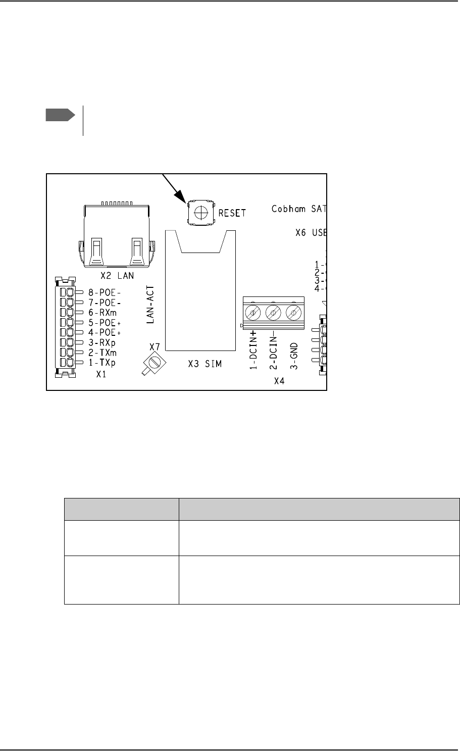
Chapter 5: Maintenance and troubleshooting
98-148232-B Reset button 77
Reset button
The EXPLORER 540 has a Reset button that has two functions: To restore all settings to factory
settings, or to restart the EXPLORER 540.
The Reset button is located inside the interface enclosure at the back of the terminal and can
only be accessed when the cover is removed.
Do as follows:
1. Use the included Torx bit to unscrew the screws holding the cover for the interface
enclosure.
2. Locate the Reset button.
3. Use a pointed device to push the Reset button.
4. Close the cover and tighten the screws carefully.
This is important in order to maintain the IP grade of the EXPLORER 540.
Note
You can disable or limit the function of the Reset button using the web interface. See
Reset button on page 73.
Action Function
Push and hold the Reset
button for 2 seconds
The EXPLORER 540 restarts (power cycle) and begins the
installation process again.
Push and hold the Reset
button for > 10 seconds
The EXPLORER 540 restores factory settings and restarts the
system. All changes to the configuration are lost and the
administrator password is reset to admin.

Chapter 5: Maintenance and troubleshooting
98-148232-B Maintenance 78
Maintenance
Cleaning the EXPLORER 540
Clean the exterior of the EXPLORER 540 with a damp cloth.
Disposal of the EXPLORER 540
Old electrical and electronic equipment marked with this symbol can
contain substances hazardous to human beings and the environment.
Never dispose these items together with unsorted municipal waste
(household waste).
In order to protect the environment and ensure the correct recycling of old equipment as well
as the re-utilization of individual components, use either public collection or private collection
by the local distributor of old electrical and electronic equipment marked with this symbol.
Contact the local distributor for information about what type of return system to use.
Troubleshooting
Troubleshooting guide
Problem Possible cause Remedy
Installation process:
The pointing process
fails
The view to the satellite is
blocked.
Make sure the EXPLORER 540 has
a clear view to the satellite.
Reboot the terminal to run
installation again.
The antenna is pointed in the
wrong direction.
Check that the antenna is pointed
according to the position data.
Adjust the position to the highest
possible signal strength.
Installation process:
“Start satellite
connection” fails
Missing SIM
SIM error
Missing PIN
Poor satellite signal
Insert SIM
Replace SIM card
Enter or cancel PIN, see To enter
the SIM PIN in the web interface
on page 74.
Check that the antenna is pointed
according to the position data,
and that nothing is blocking the
line of sight.
Adjust the position to the highest
possible signal strength.

Chapter 5: Maintenance and troubleshooting
98-148232-B Troubleshooting 79
Installation process:
“Verify satellite
connection” fails
Wrong APN
Wrong link monitoring
addresses
Network issues
Enter correct APN or select SIM
default
Enter correct link monitoring
addresses, or
disable link monitoring to skip ping
verification.
See Link monitoring on page 66.
Try again later.
To skip ping verification, disable
link monitoring.
The EXPLORER 540 is
not operational.
Software error Restart the terminal.
If the problem persists, you can
restore to factory defaults as
described in Reset button on
page 77.
Note: This will reset the
configuration of your terminal to
factory default!
The web interface
shows Insert SIM.
The SIM card is not present. Remove power and Insert the SIM
card in the SIM slot according to
the instructions in the installation
guide.
The SIM card is not inserted
properly.
Remove power and then remove
the SIM card and re-insert it
according to the instructions in
the installation guide.
The web interface
shows
No position fix.
The EXPLORER 540 is unable
to register on the network,
because the GNSS position is
unknown.
Make sure the view to the GNSS
satellites is not blocked.
To obtain position fix, the
EXPLORER 540 should be placed
flat on an even surface pointing
straight upwards, with a clear view
to as much of the sky as possible.
When the EXPLORER 540 has
obtained position fix, you can
point the antenna towards the
BGAN satellite.
You can see position status in the
Dashboard of the web interface
(status section).
Problem Possible cause Remedy

Chapter 5: Maintenance and troubleshooting
98-148232-B Troubleshooting 80
The web interface
shows
Not registered.
The EXPLORER 540 cannot
register on the BGAN
network.
Check that your SIM card is valid
for communication on the BGAN
network.
Check your subscription with the
Airtime Provider.
The web interface
shows
External control.
The EXPLORER 540 is
currently controlled by an
external application, e.g.
LaunchPad or an AT
command interface.
If you want to use the built-in web
interface, stop the external
application and restart the
EXPLORER 540. Then open your
browser and access the web
interface.
The EXPLORER 540
cannot obtain its
position using GNSS.
There is no GNSS signal, or
the signal is weak.
If the EXPLORER 540 has not
been used recently within the
same location, it can take up
to 10 minutes to obtain the
position.
Check the position status in the
web interface.
To help the EXPLORER 540 obtain
position fix, it should be placed
flat on an even surface pointing
straight upwards, with a clear view
to as much of the sky as possible.
When the EXPLORER 540 has
obtained position fix, you can
point the antenna towards the
BGAN satellite.
No signal or weak signal
from the BGAN satellite.
The view to the satellite is
blocked.
Make sure the EXPLORER 540 has
a clear view to the satellite. Be
aware that window glass may
reduce the signal level.
The antenna is pointed in the
wrong direction.
Check that the antenna is pointed
according to the position data.
Adjust the position to the highest
possible signal strength.
Connection to the
Internet cannot be
established.
The signal strength is too low. Check that the antenna is pointed
according to the position data.
Adjust the position to the highest
signal strength you can obtain.
As a rule of thumb, you should
have a a signal strength of
45 dBHz or more to be able to
make a call or data session.
Problem Possible cause Remedy
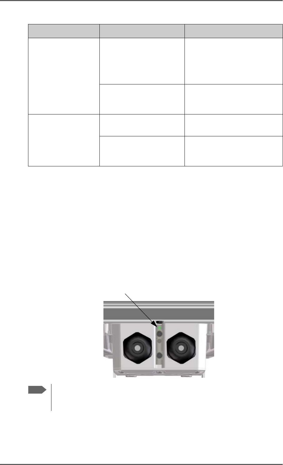
Chapter 5: Maintenance and troubleshooting
98-148232-B Troubleshooting 81
Status signalling
Means of signalling
The EXPLORER 540 system provides two methods for signalling the status of the system.
•Light indicator between the cable glands
•Messages shown in the web interface
Light indicator
The EXPLORER 540 has one light indicator showing status before and during installation. The
Status indicator (LED) is located between the two cable glands.
The web interface
cannot be accessed.
The browser is configured to
use a proxy server.
For Microsoft Internet Explorer,
select Tools > Internet Options
> Connections > LAN Settings
and uncheck Use a proxy server
for your LAN.
You have entered a wrong IP
address.
Check the IP address and re-enter
it. The default IP address is
192.168.0.1
A LAN connection
cannot be established.
The cable is not properly
connected.
Connect the cable.
The cable type is not correct. Use Ethernet Min. Cat 5 Solid
copper wire, STP. Max. length:
100 m
Problem Possible cause Remedy
Note
The LED is only in use until installation is completed, and is automatically disabled
10 minutes after the connection is established. The LED is not enabled again until
you restart the installation process.
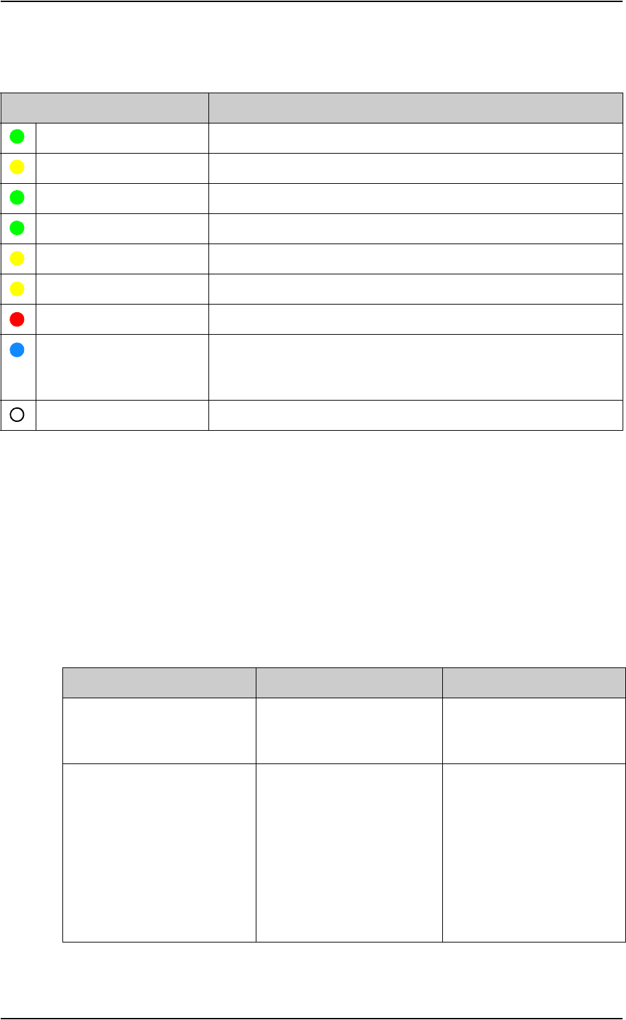
Chapter 5: Maintenance and troubleshooting
98-148232-B Troubleshooting 82
Status indicator
Event messages and status messages
In the web interface of the EXPLORER 540 you can see status messages and alerts that are
currently active.
When a warning or error event is active, the web interface shows a warning symbol . Select
it to see a list of currently active alerts.
List of messages
The following list explains some of the messages that may show in the web interface of the
EXPLORER 540.
Indicator pattern Meaning
Green flashing rapidly Starting up
Yellow flashing BGAN pointing
Green flashing Verify network connectivity
Green constant Ready
Yellow flashing rapidly Closing down
Yellow constant Warning (user recoverable). See web interface for the warning text.
Red constant Error. See the web interface.
Blue flashing Uploading software to the terminal
Note: The indicator will only flash blue if software upgrade is done
before installation. After installation the indicator is disabled.
Off Power off or light indicator has been disabled
Displayed text Explanation Remedy
Standard data speed
limited due to high
temperature
The bit rate of the data
channel is reduced because
the temperature is too high.
None
Connection closed.
Data or time limit
exceeded.
The data connection is closed
because a data limit defined
in the web interface is
exceeded.
The data limit may be set to
avoid unintentional use of
bandwidth, e.g. if you forget
to close a connection after
use.
Restart the connection e.g.
from the Dashboard in the
web interface. See Manual
activation of data
connections on page 29.
You can change the data
limits in the web interface
under Advanced > Data
limits.

Chapter 5: Maintenance and troubleshooting
98-148232-B Troubleshooting 83
Automatic activation
failed.
Reconnecting...
The terminal failed to
automatically activate a
Standard data connection at
start-up, even though it was
configured to do so.
Wait for the terminal to
reconnect.
Connection failed The terminal failed to
establish a connection.
Restart the connection e.g.
from the Dashboard in the
web interface. See Manual
activation of data
connections on page 29.
Connection lost The data connection was lost. Restart the connection e.g.
from the Dashboard in the
web interface. See Manual
activation of data
connections on page 29.
Network failure There is a problem, with the
network, e.g. congestion.
Try again later.
If the problem persists,
contact your airtime
provider.
Network failure.
Reconnecting...
There is a problem, with the
network, e.g. congestion.
The terminal tries to
reconnect because it is set up
for automatic activation.
Wait for the terminal to
reconnect.
If the problem persists,
contact your airtime
provider.
Unknown connection
problem
There is an unknown problem
with the connection.
Restart the connection e.g.
from the Dashboard in the
web interface. See Manual
activation of data
connections on page 29.
If the problem persists,
contact your airtime
provider.
Displayed text Explanation Remedy

Chapter 5: Maintenance and troubleshooting
98-148232-B Troubleshooting 84
Not registered to
the network
The terminal is not registered
on the satellite network.
You can only make a
connection if the terminal is
registered on the satellite
network.
Make sure that:
• The SIM card is present.
• The PIN has been
entered (if used).
• The terminal is pointed.
See To get started on
page 7 for details.
Closing terminal due
to high temperature
Critically high temperature is
causing the terminal to shut
down. The internal
temperature has reached 84
degrees Celsius.
None. For information on
ambient temperature, see
General specifications on
page 89.
Contact your distributor if
the problem persists.
Satellite signal
lost
The system no longer
receives a signal from the
satellite.
Make sure the antenna has a
clear view to the satellite.
Registration for
voice failed
The system has not yet been
allowed to register for voice
services (Circuit Switched).
If the problem persists,
contact your airtime
provider.
Registration for
data failed
The system has not yet been
allowed to register for data
services (Packet Switched).
If the problem persists,
contact your airtime
provider.
Preparing for
software update
The terminal is preparing to
update the software.
Wait for the software update
to complete.
Error opening
software file
A wrong file name may have
been entered with the AT
command _IUPDFW
Use the command
_IUPDFW? to show the
correct file name before
updating.
Software update is
already started
You tried to start a software
update when someone else
had already started one.
Wait until the software
update is completed.
Software version is
already installed
You are trying to update the
software to a version that is
already installed.
Check your existing software
version, e.g. in the web
interface under Control
panel > Support > About.
Displayed text Explanation Remedy

Chapter 5: Maintenance and troubleshooting
98-148232-B Troubleshooting 85
Online software
update failed
Remote software update
failed
Try again later.
If the problem persists,
contact your distributor.
Online software
update failed. Could
not establish PDP
context.
Remote software update
failed because the data
connection could not be
established. The reason may
be:
•no network resources,
•wrong APN, or
• no line of sight to the
satellite
Check the status of the
terminal, e.g. in the web
interface. Make sure there is
line of sight to the satellite
and that the APN is correct.
Online software
update failed. Could
not connect to URL.
Remote software update
failed because the terminal
could not connect to the URL.
Check that you have
specified the correct URL in
your AT command, or enter
the correct IP address
instead.
Software update
transfer error
An error occurred while
trying to transfer the file for
software update to the
terminal.
Try again later.
If the problem persists,
contact your distributor.
Software update
transfer timeout
The system timed out before
the software file was
transferred to the terminal.
Try again later.
The terminal is not
installed
The terminal has failed in the
installation process, or the
installation process was
cancelled.
If you want to restart the
installation process, restart
the terminal or access the
web interface and select
Control panel >
Installation.
Displayed text Explanation Remedy

Chapter 5: Maintenance and troubleshooting
98-148232-B Log files 86
Log files
With AT commands you can command the EXPLORER 540 to send a diagnostics report or the
Event log, System log or AT command log to a specified FTP server. See Log file(s) on page 36.
To create a diagnostics report
The diagnostic report contains relevant information for troubleshooting. When contacting
your distributor for support, please enclose this file. To generate the report, do as follows:
1. Access the web interface.
2. Select (Control panel) at the bottom of the page.
3. Select Support.
4. From the Support page, select Diagnostics report.
5. Select Generate report.
6. Select Download report.
7. Choose a location for the file and save it.
Call log and data log
The log holds detailed information on each call or data session to and from the EXPLORER 540,
including date and time, phone numbers, duration, amount of data transferred etc. Date and
time is UTC time, received from the satellite.
To see the log in the web interface, select (Control panel) > Logs. See To use the logs on
page 48.
Event log
The Event log shows events that occurred in the past and are no longer active. It includes
events of informational character describing normal phases of operation for the terminal, and
also alerts that have appeared in the Alerts list.
To view the event log in the web interface, select Event log from the Support page.
To view extended status
To see the Extended status page, select (Control panel) > Support > Extended status.
To view updated information on the Extended status page, select the icon in the top left
corner to refresh the page.
The Extended Status page shows IAI-2 status, IMSI number and IMEI number.
Note
It may take a few minutes to generate the report.

Chapter 5: Maintenance and troubleshooting
98-148232-B To reset the administrator password 87
To reset the administrator password
If you have forgotten the administrator password, do as follows:
1. Contact your supplier for a reset code.
Report the serial number and IMEI number of the terminal.
You can find the serial number on the label on the EXPLORER 540 or under (Control
panel) > Support > About and the IMEI number in the web interface under (Control
panel) > Support > Extended status.
2. After receiving the reset code from your supplier, select Reset password from the
Support page.
3. Type in the reset code obtained from your supplier and select Reset.
4. The password is reset to admin.
Help desk
Under Help desk you can enter the contact information you want for your EXPLORER 540. The
Help desk contact information is empty by default. You must provide the contact information,
e.g. the phone number for your Airtime Provider under Advanced > Help desk. For details on
how to enter the information, see Help desk on page 73.
The Help desk information is then available from the About page ( (Control panel) >
Support > About)

Chapter 5: Maintenance and troubleshooting
98-148232-B List of reserved IP subnets 88
List of reserved IP subnets
Some IP subnets are reserved for internal use in the terminal. If any of these addresses are
assigned to external equipment connected to the terminal, the terminal and connected
equipment will not be able to communicate.
The following local IP subnets are reserved for internal use in the terminal. The netmask for all
of these subnets is 255.255.255.0.
192.168.1.x
192.168.2.x
192.168.3.x
192.168.4.x
192.168.5.x
192.168.6.x
192.168.7.x
192.168.8.x
192.168.9.x
192.168.10.x
192.168.11.x
192.168.12.x
192.168.13.x
(“x” means all numbers from 0 to 255)

98-148232-B 89
Appendix A
Technical specifications A
General specifications
Item Specification
Type EXPLORER 540, BGAN M2M terminal/ BGAN Class 2 terminal
Max. IP data rate, Rx/Txa
Streaming datab
a. Performance depends on a wide range of factors and actual usage.
b. Not available for M2M subscription.
464 kbps/448 kbps (simultaneously)
32, 64, and 128 kbps
VoicebStandard voice 4 kbps
Premium voice 3.1 kHz audio, 64 kbps
Physical dimensions 202 x 202 x 51.8 mm
8.0 x 8.0 x 2.0 inches
Weight 1.6 kg / 3.5 lbs
Operating temperature
Storage temperature
-40 to 75°C , reduced operationc
-40 to 55°C, full operation
-40 to 75°C
c. When the internal temperature reaches 84°C, the terminal closes down. An event message is recorded in
the event log.
Water & Dust IP66
Environment condition Outdoor mounting and use in harsh environment
Max. altitude for Hazardous
locations
2000 m
Relative humidity 95% humidity non-condensing at 40°C
pollution degree Pollution degree 2
Supported web browsers
(Others may be supported,
these have been tested.)
Safari 5.1.7 and above
Internet Explorer 9.0 and above
Google Chrome 23 and above
Mozilla Firefox 16 and above
Approvals CE, FCC, IC, RCM, GMPCS, C1D2, Russia (Type approval
certificate in the field of communication), Japan (Radio law),
Inmarsat Class 2 Type Approval and BGAN M2M Certified
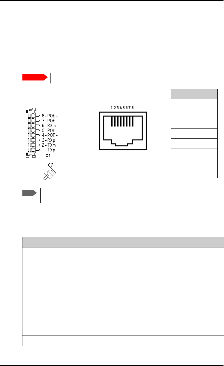
Appendix A: Technical specifications
98-148232-B Interfaces specifications 90
Interfaces specifications
LAN interface (X1 or X2)
Connector pin-out
To insert the wires in X1 use a screwdriver (max. 2mm wide) to push each terminal open.
Specifications
Important
There are two LAN connectors, but only one at a time can be used!
Pin Function
1TXp
2TXm
3RXp
4POE+
5POE+
6RXm
7POE-
8POE-
Note
If you connect to the terminal block X1 you must connect the shield of the cable to
the screw terminal X7 (GND).
X1: Terminal block
and X7 (GND)
or
Female (receptacle)
X2: RJ-45 connector
and
Item Specification
Number of connectors 2: X1 or X2 - only one at a time available!
The two connectors are on the same electrical interface.
Connector types RJ-45 female or spring loaded terminals
Standard ISO/IEC 8877:1992 and PoE+ IEEE 802.3at type 2 class 4
NOTE: The EXPLORER 540 is a Powered Device (PD), that is it
may be powered by PoE from external Power Sourcing
Equipment (PSE), but it cannot supply PoE
Power consumption Power save mode (“wake-on” functions): 800 mW
Sleep mode: 3.2 W
Transmitting: max. 24 W
Max. data rate 10/100 Mbps

Appendix A: Technical specifications
98-148232-B Interfaces specifications 91
DC power input (X4)
Connector pin-out
To unscrew and fasten the screws in X4 use a screwdriver (max. 3.5 mm wide). If the DC cable
is shielded, connect the shield to pin 3, GND. Otherwise leave GND unconnected.
Specifications
I/O connector (X5)
Connector pin-out
Max. cable length 100 m / 328 ft with Cat5 UTP
Item Specification
Pin Function
1DCIN+
2DCIN-
3GND
Screw
terminal
Item Specification
DC input range (min-max)
DC input, nominal
10.5 to 32 VDC
12 or 24 VDC
Transient overvoltage Overvoltage category II
Power consumption Power save mode (“wake-on” functions): 110 mW
Sleep mode: 2.5 W
Transmitting: max. 21 W
Connector type Screw terminals
Pin Function
1 Request wake up (input)
2Terminal ready (output)
3 Control/Status Input/output
4GND
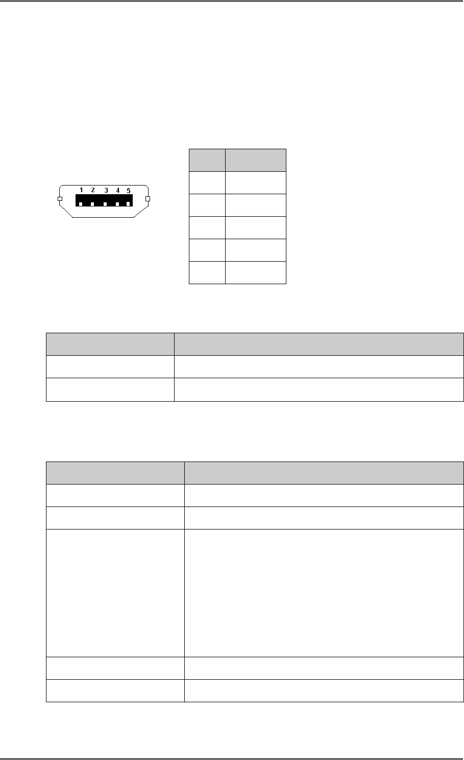
Appendix A: Technical specifications
98-148232-B Built-in BGAN antenna 92
To insert the wires in X5 use a screwdriver (max. 2mm wide) to push each terminal open.
For configuration of the I/O pins, see Power save (Settings) on page 71
USB (Host) interface (X6, Future use)
Connector pin-out
Specifications
Built-in BGAN antenna
Pin Function
1+5V
2Dm
3Dp
4ID
5GND
USB Micro B
Item Specification
Version USB v2.0 Host
Connector type Type Micro B
Item Specification
Type Directional patch array, manually adjustable
Polarization RHCP, Right-hand circular polarization for both tx and rx
Frequencies
Inmarsat I-4
Transmit
Receive
Inmarsat Alphasat (EMEA)
Transmit
Receive
GNSS
1626,5 MHz - 1660,5 MHz
1525 MHz - 1559 MHz
Extended L-band (XL)a:
1626,5 MHz - 1660,5 MHz and 1668 MHz - 1675 MHz
1518 MHz - 1559 MHz
GPS, GLONASS, Beidou
a. Only available within Alphasat coverage (EMEA). See BGAN services on page 5.
EIRP Nominal: 15.1 dBW ±1dB, Class 2
Gain 11.25 dBi
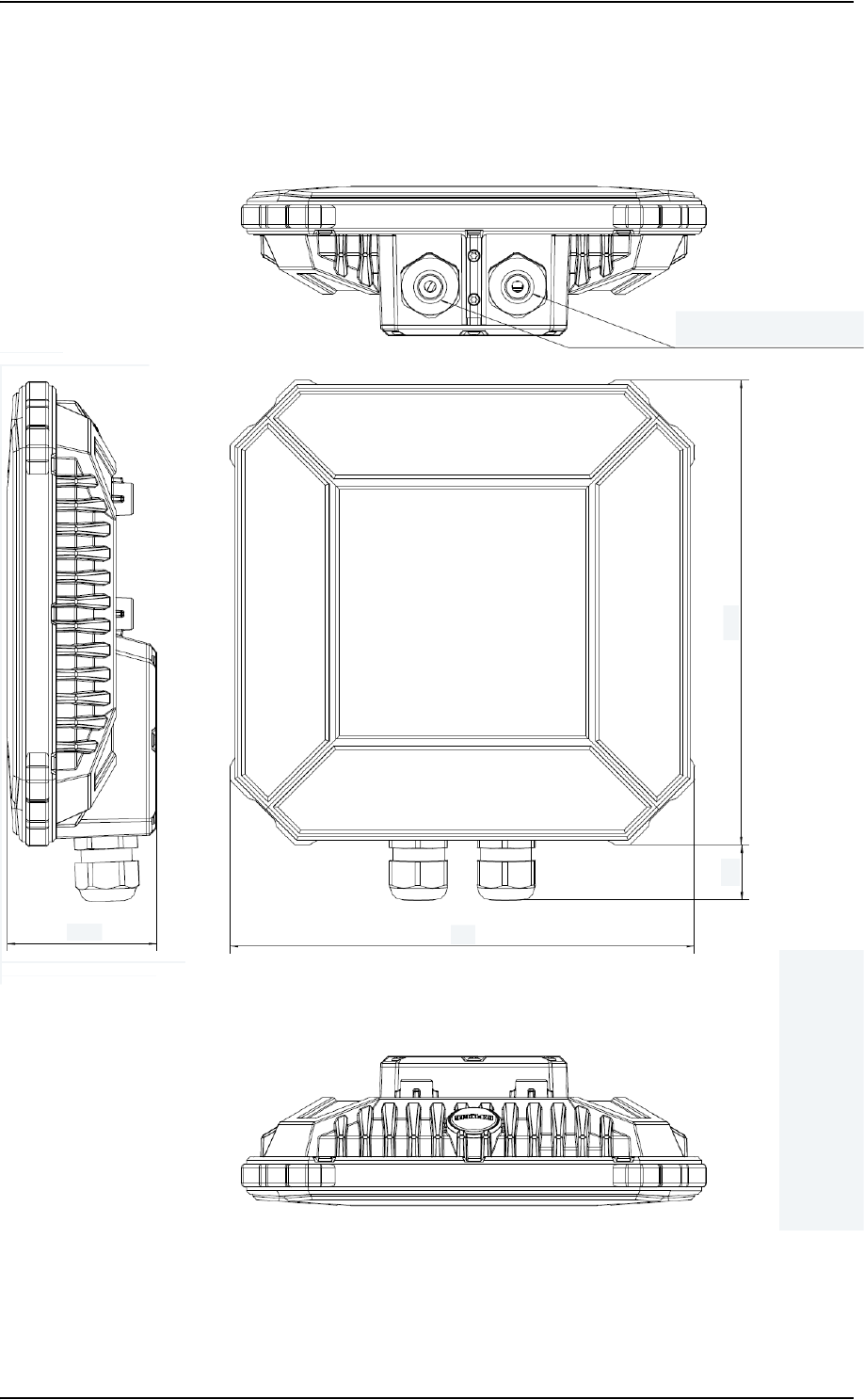
Appendix A: Technical specifications
98-148232-B Outline drawing 93
Outline drawing
Dimensions are in millimeter
65 202
24 202
2 x cable glands for cable
diameter Ø5 to Ø10 mm
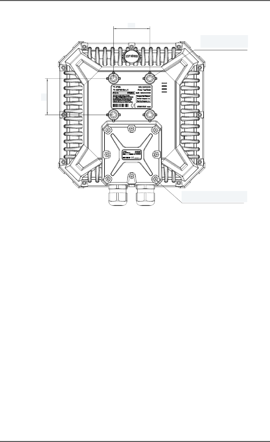
Appendix A: Technical specifications
98-148232-B Outline drawing 94
50
50
Screw Torx 10 with
security pin, 8 places
M6 4 places
Max. screw length 9 mm
Dimensions are in mm

98-148232-B 95
Appendix B
Command reference B
This appendix lists the function, syntax and parameters for commands used with the EXPLORER 540. You
can send commands to the EXPLORER 540 either with an SMS or with AT commands. SMS is very useful
for remote operation, because you only need the terminal’s mobile number to access the terminal. There
is one section for each type of command:
•SMS remote commands
•AT commands
SMS remote commands
The following SMS commands are supported:
•ACTIVATE
•DEACTIVATE
•CLEAR
•GETINFO
•RESTART
•WATCHDOG
•ATCO
•ADPWRST
Syntax conventions
Syntax definitions use the following conventions:
• <parm> indicates that a parameter (without < and >) can be filled in by the user.
• { <opt1> | <opt2> | … | NA } indicates that one of various options must be chosen by the
user. Use NA when no value is defined.
• Keywords and parameters are separated by the space (ASCII 32) character.
• The command name and all keywords must be in upper case; most user-provided
parameters are case sensitive but may be either case.
•TE means Terminal Equipment - the equipment connected locally to the EXPLORER 540.

Appendix B: Command reference
98-148232-B SMS remote commands 96
SMS remote command summary
Commands
The table below summarizes the available SMS remote commands. Empty cells means no
parameters and no placeholders (the password comes just after the last parameter).
Parameters
The table below summarizes the available parameters for the SMS remote commands.
Command Parm1 Parm2 Parm Parm Parm Parm Parm Password
ACTIVATE <qos> <PC/TE type> <apn> <user> <pwd> <rsms_pwd>
DEACTIVATE <qos> <PC/TE type> <rsms_pwd>
CLEAR <category> SMS <rsms_pwd>
GETINFO <info_mode> <dataset> <rsms_pwd>
RESTART <reset_type> BGAN <rsms_pwd>
WATCHDOG <wdog_op> <ping1> <ping2> <ping3> <ping_
always>
<ping_
interval>
<wdog_
enable>
<rsms_pwd>
ADPWRST 1 <imei> <rsms_pwd>
ATCO <resp_mode> <rsms_pwd> <at_cmd>
Parameter Values Meaning
<qos> 1 Standard/background data (currently the only qos available for M2M)
<PC/TE type> DHCP
STATIC
AWO
<name>
<IP addr>
ANY
All TEs known via DHCP
All TEs known via Terminal settings
Always On, deactivate all PDP contexts including context established with
ACA
Name of specific TE, as known by DHCP server
IP Address of specific TE (or Global IP for DEACTIVATE)
Any/all TEs attached (DEACTIVATE: all except PDP context established with
ACA)
<apn> <APN>
NA
APN name, e.g. bgan.inmarsat.com
Placeholder when no APN is specified. Default APN is used.
<user> <APN user name>
NA
User name associated with APN
Placeholder when no APN user name is specified
<pwd> <APN password>
NA
Password associated with APN username
Placeholder when no APN password is specified

Appendix B: Command reference
98-148232-B SMS remote commands 97
<rsms_pwd> <rsms_pwd> Remote SMS password
<category> 1
2
3
4
Delete only Read SMS messages
Delete Read and Sent
Delete All except Unread
Delete All SMS messages
<info_mode> 1
2
For GPS query: position data only. For other queries: use verbose mode (with
titles)
For GPS query: position data plus SMS usage. For other queries: use terse
mode (no titles)
<dataset> GPS
USAGE
ALL
GPS position
Cumulative call time and data usage
GPS position plus call time and data usage
<reset_type> 1 Normal delay restart
<wdog_op> 1
2
Get watchdog configuration
Set watchdog parameters
<ping[1/2/3]> <IP addr>
NA
Up to three ping destination IP addresses
Placeholder when no IP address is specified
<ping_always> 0
1
NA
Send ping only if no traffic
Always send ping, regardless of data traffic
Placeholder when no value is specified
<ping_interval> <integer>
NA
Interval between pings (minutes)
Placeholder when no value is specified
<wdog_enable> 0
1
NA
Disabled
Enabled
Placeholder when no value is specified. The existing setting applies. Used if
you want to change one of the other parameters without changing the
enabled/disabled setting.
<imei> <14 digits> IMEI of the EXPLORER 540, without dashes or check digit
<resp_mode> 0
1
2
3
None – send no responses to AT commands
Immediate - immediate responses, but not unsolicited
Final – suppress immediate if OK, plus unsolicited
All – send both immediate and unsolicited responses
<at_cmd> <at_cmd> AT command, without prefix AT. For supported AT commands, see ATCO
commands on page 100.
Parameter Values Meaning

Appendix B: Command reference
98-148232-B SMS remote commands 98
SMS reject responses
Reject Response SMS Possible Cause
WRONG PASSWORD Authentication Failure
ATCO ERROR Unable to send AT command to ATC handler
COMMAND NOT SUPPORTED Attempt to use an SMS command not
supported by the target platform
WRONG QOS Invalid QoS Requested (only a QoS of 1 is
valid).
WRONG CONNECTION TYPE(NO DHCP TE) No DHCP TEs connected to the Remote Unit
WRONG CONNECTION TYPE(NO STATIC TE) No Static TEs added in Terminal settings
WRONG CONNECTION TYPE(NO TEs) No TEs are connected to the Remote Unit
ACT/DEACT PARM PROBLEM The <IP addr> provided for an ACTIVATE or
DEACTIVATE command is incorrect (for
ACTIVATE, it must be in same subnet as the
EXPLORER 540 IP and not be the
EXPLORER 540 IP; for DEACTIVATE, it must
exist as a local or global IP address in the
existing PDP table).
INVALID RESTART REQUEST Attempt to perform restart before
EXPLORER 540 has been running for at least
15 minutes
INVALID WATCHDOG PING ADDRESS Entered Ping address is out of range (0.0.0.0
– 255.255.255.254)
INVALID WATCHDOG PING FREQUENCY Requested Ping Frequency is less than the
minimum (5 minutes)
INVALID WATCHDOG REQUEST "Ping required" or "wdog enabled" fields
incorrect in remote SMS message, or
watchdog request other than "get" attempted
ERROR: TERMINAL BUSY An ACTIVATE or DEACTIVATE command is
in progress

Appendix B: Command reference
98-148232-B AT commands 99
AT commands
The following most used AT commands are explained in this manual. Other AT commands not mentioned
here may still be supported.
Syntax conventions
Syntax definitions use the following conventions:
• <parm> indicates that a parameter (without < and >) can be filled in by the user.
• { <opt1> | <opt2> | … | NA } indicates that one of various options must be chosen by the
user. NA means no value is defined.
[<options>] indicates that <options> may or may not be included in the command.
• String parameters must be enclosed in double-quotes (ASCII 34) and numeric parameters
must not be. Only the ASCII double-quote is recognized; slanted quotes, e.g. from the
Windows-1252 or UTF-8 character sets, are not valid.
• Keywords and parameters are separated by commas.
• The command name and all keywords must be in upper case; most user-provided
parameters are case sensitive but may be either case.
•TE means Terminal Equipment - the equipment connected locally to the EXPLORER 540.

Appendix B: Command reference
98-148232-B AT commands 100
M2M related AT commands
The tables below summarize some of the most used AT commands for M2M operation.
Parameters are explained in Parameters for other M2M related AT commands on page 104.
ATCO commands
The table below summarizes the ATCO commands, i.e. AT commands that can be used in the
SMS command ATCO.
Command Parm1 Parm2 Parm3 Parm4 Parm5 Parm6 Parm7 Parm8 Parm9
_IGETFW <mode> [<ftp
server>]
[<ftp
uname>]
[<ftp
passwd
>]
[<apn>] [<apn
uname>]
[<apn
passwd>]
_IUPDFW <filename>
_ISENDFILE <local dir> <filena
me>
<ftp dir> <ftp
server>
<ftp
uname>
<ftp
passwd>
[<apn>] [<apn
uname>]
[<apn
passwd>]
_IGETFILE <ftp dir> <filena
me>
<local
dir>
<ftp
server>
<ftp
uname>
<ftp
passwd>
[<apn>] [<apn
uname>]
[<apn
passwd>]
_IUPDCFG <filename>
_IREMWEB <enable> <ip_ad
dr_lo>
[<ip_addr
_hi>]
[<apn>] [<apn
uname>
]
[<apn
passwd>
]
_IATCROBSTa
a. Robustness for 3GPP LTE signals, not ATC
<enable>
_ICPWD <type> <old
passwd
>
<new
passwd>

Appendix B: Command reference
98-148232-B AT commands 101
Parameters for ATCO commands
Parameter Values Meaning
<mode> 0
1
Deferred activation
Immediate activation
<ftp server> <ftp server>
NA
Host name or IP address of the ftp server
Placeholder when no ftp server is specified. Default ftp server is used.
<ftp uname> <ftp uname>
NA
User name for the ftp server
Placeholder when no ftp server is specified
<ftp passwd> <ftp passwd>
NA
Password for the ftp server
Placeholder when no ftp server is specified
<apn> <apn>
NA
APN name
Placeholder when no APN is specified. The default APN from the SIM is used.
<apn uname> <apn uname>
NA
User name for the APN
Placeholder when no APN is specified
<apn passwd> <apn passwd>
NA
Password for the APN
Placeholder when no APN is specified
<filename> <filename> The name of the file to use, including extension
<local dir> <local dir> The name of the local directory in the EXPLORER 540 to use for getting or
saving a file
<ftp dir> <ftp dir> The name of the directory on the ftp server to use for getting or saving a file
<enable> 0
1
Disable
Enable
<ip_addr_lo> <ip_addr_lo> IP address of the HTTP client that should be allowed remote access to the
EXPLORER 540,
or, the lowest address in a range of IP addresses, if a range of addresses is
allowed.
<ip_addr_hi> <ip_addr_hi> The upper IP address of a range of allowed IP addresses. This parameter is
optional; if omitted, only the specified single IP address <ip_addr_lo> may
access the EXPLORER 540.
<type> AD
RS
The type of password is administrator password
The type of password is remote SMS password
<old passwd> <old passwd> The old password that is already in the system
<new passwd> <new passwd> The new password to be used after this command. Note that quotes (“) and
commas (,) and spaces ( ) are not allowed.

Appendix B: Command reference
98-148232-B AT commands 102
ATCO response codes
The following response codes apply to the AT commands supported by SMS.
Code Text Explanation
General codes
0 Complete Operation completed successfully
1 Unexpected software error Software error
2 Local file open error _IGETFILE: could not open local file after download
_ISENDFILE: could not open local file
_IUPDCFG: Loading configuration failed. Incompatible file
format.
3 Directory not found Could not find specified directory on local file system.
4 File not found Could not find specified file name on local file system.
5 Error renaming file Could not restore after failed upgrade.
Context Management codes
13 Context activation error Context activation failed. Could be problem with PS attach,
SIM subscription, APN, network or connectivity.
FTP Management codes
20 FTP hookup fail Connection to FTP server failed. Problem could be server
unreachable or specified IP address or server name invalid, or
connectivity failure.
21 FTP login fail FTP user name or password incorrect
23 FTP ‘cwd’ fail Could not change to working directory on FTP server.
24 FTP data connection fail Could not establish an FTP data connection with the server.
26 FTP xfer command fail Could not initiate data transfer on an established connection.
May be caused if filename not found.
29 FTP socket fail Error while reading or writing FTP data socket.
31 FTP xfer timed out FTP client timed out waiting for socket ready (read or write),
e.g. due to loss of connectivity during transfer.
_IGETFW command codes
40 File in use, cannot download The file to be downloaded is the same as the image currently
in use.
41 Starting immediate upgrade… Normal success. File downloaded successfully, now starting
immediate update.

Appendix B: Command reference
98-148232-B AT commands 103
_IUPDFW command codes
50 New firmware file not found Could not find specified filename.
51 New firmware file corrupt New firmware file corrupt.
52 New firmware file failure The new firmware failed to run or failed to acquire the
network and the unit fell back to the old release.
54 Upgrade status file error Previous update has not finished yet.
_IREMWEB command codes
81 Global IP: <ip_addr> REMWEB connection set up successfully. Indicates global IP
address assigned to the EXPLORER 540’s own PDP context, to
which an HTTP connection may be made.
Code Text Explanation

Appendix B: Command reference
98-148232-B AT commands 104
Other M2M related AT commands
Parameters for other M2M related AT commands
The table below summarizes the available parameters for the AT commands for M2M
operation.
Command Parm1 Parm2 Parm3 Parm4
_ISMSRMT <enable>
_ICLCK <type> <enable> <passwd>
_IPWSAVSCHD <psmode> <psvalue>
_IMACLOC <enable> <interface> [<interface>]
_IMACLOCAD <action> <interface> <MAC Address> [<MAC
Address>]a
a. Up to 10 MAC addresses may be specified.
_ITGPIO <active>
Parameter Values Meaning
<enable> 0
1
Disable
Enable
<passwd> <passwd> The existing administrator password
<psmode> IDLE_TRG
TOD_TRG
The power save mode to be set up is “idle trigger”, that is the time with no
activity before entering power save mode
The power save mode to be set up is “time of day”, that is a specific time of
day where the EXPLORER 540 wakes up from power save mode.
<psvalue> <idle-minutes>
<HH:MM>
Used with IDLE_TRG (above). Number of minutes (e.g. 15)
Used with TOD_TRG (above). Time of day (e.g. 23:30)
<interface> 0 0 means Ethernet interface. This is the only option.
<action> 0
1
Delete
Add
<MAC
Address>
<MAC Address> MAC address(es) for MAC locking. Up to 10 MAC addresses are permitted.
<active> 0
1
Inactive. The GPIO pin is in its inactive state.
Active. The GPIO pin is in its active state.

Appendix B: Command reference
98-148232-B AT commands 105
Context management AT commands
The table below summarize some of the most used AT commands for context management.
Parameters are explained in the table in the next section.
Parameters for context management AT commands
The table below summarizes the available parameters for the AT commands for context
management.
Command Parm1 Parm2 Parm3 Parm4 Parm5 Parm6 Parm7
+CGDCONT <cid> <protocol> <apn> <apn
uname>
<apn_passwd>
+CGEQREQ <cid> <Traffic
Class>
<Max bitrate
UL>
<Max
bitrate DL>
<Guaranteed
bitrate UL>
<Guaranteed
bitrate DL>
+CGEQMIN <cid> <Traffic
Class>
<Max bitrate
UL>
<Max
bitrate DL>
<Guaranteed
bitrate UL>
<Guaranteed
bitrate DL>
+CGTFT <cid> <packet
filter
identifier>
<evaluation
precedence
index>
<source
addr &
subnet>
<protocol
number>
<destination
port range>
<source
port range>
+CGDSCONT <cid> <p_cid>
+CGACT <state> <cid>
+CGPADDR <cid>
Parameter Values Meaning
<cid> <cid> The Context Identifier (1 – 11) for the PDP context
<protocol> <protocol> The transport protocol (IP or PPP)
<apn> <apn>
NA
APN name
Placeholder when no APN is specified. The default APN from the SIM is used.
<apn uname> <apn uname>
NA
User name for the APN
Placeholder when no APN is specified
<apn passwd> <apn passwd>
NA
Password for the APN
Placeholder when no APN is specified
<Traffic Class> 1
3
Streaming (not available for M2M subscription)
Standard data (Background)
<Max bitrate
UL>
<Max bitrate UL>
NA
The maximum bit rate up link (32, 64, 128)
Placeholder when Standard data is selected
<Max bitrate
DL>
<Max bitrate DL>
NA
The maximum bit rate down link (32, 64, 128)
Placeholder when Standard data is selected

Appendix B: Command reference
98-148232-B AT commands 106
<Guaranteed
bitrate UL>
<Guaranteed
bitrate UL>
NA
The guaranteed bit rate up link (32, 64, 128)
Placeholder when Standard data is selected
<Guaranteed
bitrate DL>
<Guaranteed
bitrate DL>
NA
The guaranteed bit rate down link (32, 64, 128)
Placeholder when Standard data is selected
<packet filter
identifier>
<packet filter
identifier>
The packet filter identifier (1 – 8)
<evaluation
precedence
index>
<evaluation
precedence
index>
The evaluation precedence index defines the order in which the traffic flow
filters are applied to packets. 0 is first, then 1, 2 etc.
<source addr &
subnet>
<source addr &
subnet>
This is an IPv4 IP address and subnet mask. (0.0.0.0.0.0.0.0 to
255.255.255.255.255.255.255.255)
<protocol
number>
<protocol
number>
This number is uniquely assigned for the protocol being used. TCP is set to 6,
and UDP is set to 17. The protocol number determines which protocol is
used by the traffic flow filter. (0-255)
<destination
port range>
<destination port
range>
Destination port range in the form From.To
To indicate only one port number, type in the same port number under From
and To.
Example: 65333.65338 indicates port numbers from 65333 to
65338, both included.
<source port
range>
<source port
range>
Source port range in the form From.To
See above for example
<p_cid> <p_cid> The primary context to which the secondary context is related
<state> 0
1
Deacativate
Activate
Parameter Values Meaning

Appendix B: Command reference
98-148232-B AT commands 107
Message (SMS) configuration AT commands
The following AT commands are used for configuration of SMS.
Note
For details on parameters for the message configuration commands, see the 3GPP
standard ETSI TS 127 005 V4.2.1.
Command Parm1 Parm2 Parm3 Parm4 Function
+CSMS <service> Select Message Service
+CPMS <mem1> [<mem2> [<mem3>]
]
Preferred Message Storage
+CMGF <mode> Message Format
+CSCA <sca> [<tosca>] Service Center Address
+CSMP [<fo> [<vp> [<pid> [<dcs>]]]
]
Set Text Mode Parameters
+CSDH <show> Show Text Mode Parameters
+CNMI [<mode> [<mt> [<bm> [<ds>]]]] New Message Indications to TE
+CMGL <stat> List Messages
+CMGR <index> Read Messages
+CMGS <da/mr> [<toda/scts
>]
Send Message
+CMGD <index> Delete Message
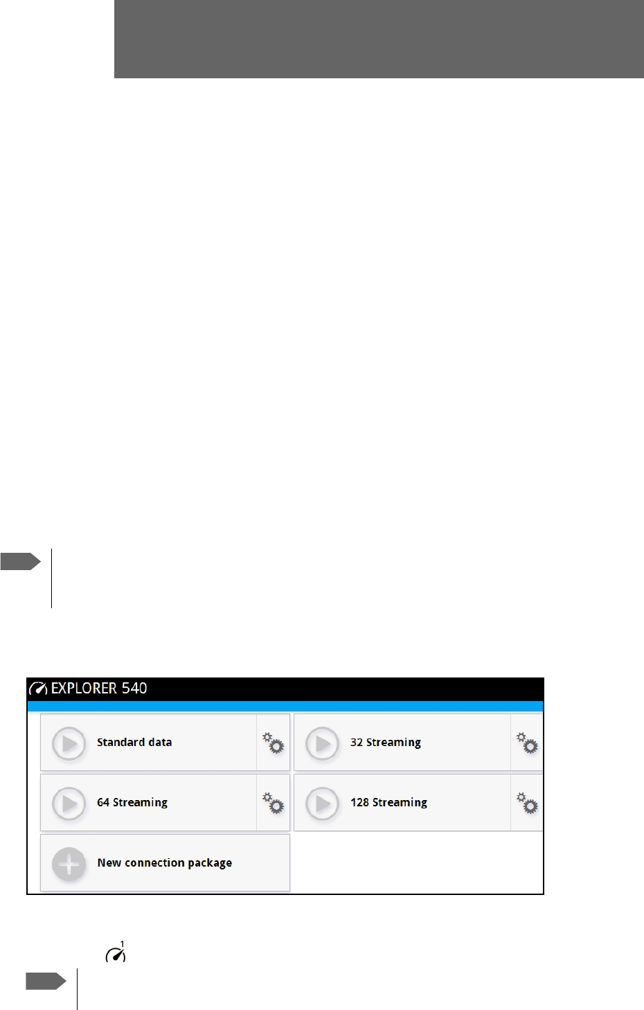
98-148232-B 108
Appendix C
BGAN non-M2M functions C
This appendix includes the features and functions in the EXPLORER 540 that are not available with an
M2M subscription, but only with a standard BGAN subscription.
These functions are:
•Streaming
•VoIP
To control data connections from web interface (BGAN)
The startup page of the web interface is used to start and stop data connections and to set up
the data connections.
The difference from the M2M version is, that Streaming connections are supported.
To start and stop data connections
To start and stop data connections on your EXPLORER 540, do as follows:
1. In the opening page, locate the connection package you want to start.
2. Click to start the connection. If more connections are included in the connection
package, this will start all included connections. The connections icon at the bottom of the
page shows when a BGAN data connection package is running.
3. Click to stop the connection.
Note
The icons for starting and stopping connections are only displayed if the
terminal is ready and registered on the BGAN network. Otherwise you cannot start
data connections.
Note
Once a Streaming connection is started, the connection will run until you stop it.
You will be charged for the time you are connected.

Chapter C: BGAN non-M2M functions
98-148232-B To control data connections from web interface (BGAN) 109
If the connection fails, the connection tile shows an exclamation mark and an error
message. The error message is also shown in the data log, see Data log on page 48.
When a connection is active, the icon changes to and the tile for the active connection
shows:
• IP address: The IP address that has been assigned by the service provider to this session.
• Transferred data: For Standard data, the tile shows the total amount of transmitted and
received data since the connection was established.
• Connection duration: For Streaming data, the tile shows the total time the connection has
been active.
• Bit rate: For Streaming connections, the tile shows the fixed bit rate.
Default data connection types
By default, the following connections are available:
You can use these connections as they are or build your own connection packages. For set up
of the connection packages, see the next section.
Name Type of connection
Standard data Several users can share the data connection. This type
of connection is ideal for TCP/IP traffic such as e-mail,
file transfer, and Internet/intranet access.
The user pays for the amount of data sent and
received.
Streaming data
The following Streaming classes are
available:
32, 64, or 128 Streaming
An exclusive, high-priority connection, ensuring
seamless transfer of data. This type of connection is
ideal for time critical applications like live video over
IP.
The user pays for the duration of the connection.
Note that Streaming is not available in M2M
subscriptions.
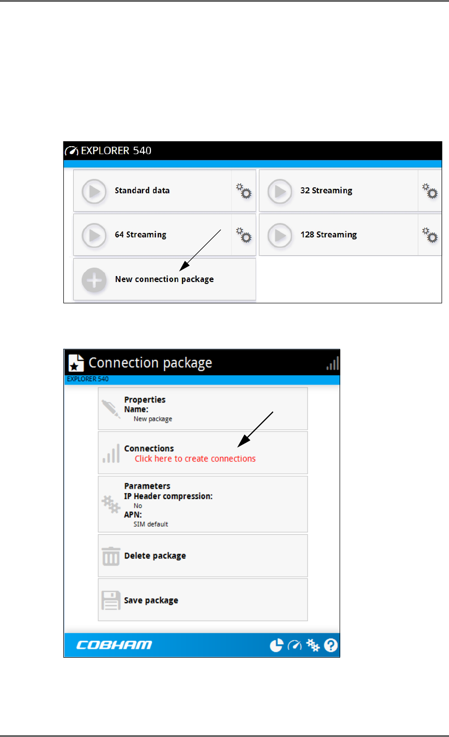
Chapter C: BGAN non-M2M functions
98-148232-B To set up data connections 110
To set up data connections
To create a new connection package
Do as follows:
1. Click New connection package.
2. Type a name for the new package and click Save.
3. Click Click here to create connections.
4. Select the connection type you want for your new connection package.
You can select Standard, Streaming 32 kbps, Streaming 64 kbps or Streaming 128 kbps.

Appendix C: BGAN non-M2M functions
98-148232-B To make phone calls over BGAN (not M2M version) 111
5. Click Save package.
The new package should now appear as a new tile on the startup page.
For details on Parameters (APN and IP Header compression) see To change the APN for a
connection package on page 43.
To make phone calls over BGAN (not M2M version)
To connect a VoIP phone or smartphone
Your VoIP phone or smartphone can be set up to make and receive calls over the BGAN
network, using the terminal’s phone number.
To connect your phone for making calls
For details on initial setup of your VoIP phone and the EXPLORER 540, see
• The documentation for your handset
•First time SIP setup on page 112
•To manage VoIP phones or smartphones on page 114
To connect a VoIP phone, do as follows:
1. Start up the EXPLORER 540 terminal.
2. Connect your phone via a router/switch to the LAN interface on the EXPLORER 5401.
When the VoIP phone is powered and ready, you are able to make and receive calls over BGAN.
Note
Phone calls are only possible if:
• The EXPLORER 540 is connected to the BGAN satellite network, and
• The airtime subscription is a class 2 subscription (not M2M)
Note
Make sure your VoIP phone has an integrated SIP client. The EXPLORER 540 has an
integrated SIP server.
1. Since there is only the one LAN interface and the EXPLORER 540 cannot provide power, you must
connect the phone(s) via external equipment such as a router (wired or wireless) or a switch.

Appendix C: BGAN non-M2M functions
98-148232-B To make phone calls over BGAN (not M2M version) 112
First time SIP setup
If it is the first time you connect your phone to the EXPLORER 540 for making calls, you must
first set up the SIP server details in your phone. For information how, see the user
documentation for your phone. You may be asked to enter some of the following details:
• SIP server address and port: Default address: 192.168.0.1, Port: 5060
• User name: Local number in EXPLORER 540 (0501 to 0516)
• Password: Default same as user name
• Codec priority: Highest priority codec type: G.711
Call types
Definition
The phone connection can be a Standard voice connection or a 3.1 kHz audio connection.
•For outgoing calls, the call type is Standard voice by default.
You can change the call type for your call to 3.1 kHz audio by dialling 2* before the
number.
Example: 2*004539558800
• For incoming calls, you can set up in the web interface (IP handset page) which call types
you want to receive on your smartphone or IP handset. Only the call types selected for a
smartphone/IP handset are received. By default all, call types are accepted.
When receiving calls, the mobile number determines which call type is used. In your airtime
subscription you have one number for 3.1 kHz audio and one number for Standard voice.
Remember that the call is only received on your phone if the call type used is selected for that
phone (called IP handset in the web interface).
For information on how to set up the call types in the web interface, see To manage VoIP
phones or smartphones on page 114.
To make or receive a phone call with EXPLORER 540
Connect your smartphone or IP handset as described in To connect a VoIP phone or
smartphone on page 111.
To make a call from the EXPLORER 540
To make a call, dial 00 <country code> <phone number> followed by off-hook key.
Example: To call Cobham SATCOM in Denmark (+45 39558800),
dial 00 45 39558800
If there was an error establishing the connection, the web interface of the EXPLORER 540
shows an error message.
Note
The user name and password must match the IP handset settings in the
EXPLORER 540. See To manage VoIP phones or smartphones on page 114.

Appendix C: BGAN non-M2M functions
98-148232-B To make phone calls over BGAN (not M2M version) 113
To receive a call
By default, all phones connected to the EXPLORER 540 will ring when one of the mobile
numbers is called. Note however, that this depends on the call type settings. See Call types on
page 112.
Information on missed calls is stored in the call log. You can see the call log in the web
interface (Control panel > Logs > Call log).
To make a call to the EXPLORER 540
To make a call to a phone connected to the EXPLORER 540, dial + <Mobile number>
• + is the prefix used in front of the country code for international calls. This is 00 when
calling from countries in Europe and from many other countries.
•Mobile number. The first part of the mobile number is always 870, which is the “country
code” for the BGAN system. For information on the mobile numbers, refer to your airtime
subscription.
Local numbers and special functions
Overview
There are a number of local numbers and dialing functions available in the EXPLORER 540.
The following list shows the allocated local numbers and special-purpose numbers for the
EXPLORER 540.
Apart from the numbers above, the EXPLORER 540 uses the following dialing prefixes:
•1* before the phone number will force the connection to use Standard voice.
•2* before the phone number will force the connection to use 3.1 kHz audio.
•#31# before the phone number will hide the callers phone number to the recipient.
•*31# before the phone number will show the callers phone number to the recipient where
it would otherwise be hidden, e.g. because the number is an ex-directory number.
Note
There are two mobile numbers, one for 3.1 kHz audio and one for Standard
voice.
Number Function
0 followed by one of the numbers
501-516 and off-hook key
Local call to one smartphone or IP handset.
0900 followed by off-hook key Local call broadcast to all connected phones.

Appendix C: BGAN non-M2M functions
98-148232-B To manage VoIP phones or smartphones 114
To manage VoIP phones or smartphones
Overview
This section describes how to manage VoIP phones or smartphones connected to the
EXPLORER 540.
The terminal supports connection of up to 16 phones through the LAN interface. Each phone
must have a local number in the range 0501 to 0516 as well as a unique password. For details,
see the next section.
For details on SIP settings and how to connect your phone to the LAN interface, see To
connect a VoIP phone or smartphone on page 111.
To manage VoIP phones or smartphones in your EXPLORER 540
Do as follows:
1. Connect your smartphone or your VoIP phone via a router/switch to the LAN interface. For
details, see To connect a VoIP phone or smartphone on page 111.
2. In the web interface, select (Control panel) > IP handsets.
3. Click the tile for the handset number you want to manage.
4. Select Enable to enable the handset.
•
on the tile for your handset means the handset is disabled.
•
on the tile for your handset means the handset is enabled.
5. To change the Password, simply type in the new number.
6. Set the call type for incoming calls.
You can select Standard voice or 3.1 kHz audio or both.
• If you select both, the handset will react (ring) on incoming calls.
• If you select e.g. Standard voice, the handset will only react on calls made to the
Standard voice phone number.
7. Select the Preferred outgoing call type.
The selected type will be used by default, if possible, for any outgoing call from this
handset.
8. Click Save.
9. In the smartphone or IP handset, enter the local number and the password you just
entered in the EXPLORER 540. See the documentation for your handset for details.
The handset remains in the list after disconnecting. When the handset is connected again, it is
automatically recognized and ready for use, if enabled.
Note
It may take some seconds to enable the handset.
Note
The user name is also the local number for the handset.

98-148232-B 115
Appendix D
Conformity D
CE (R&TTE)
The EXPLORER 540 is CE certified (R&TTE directive) as stated in “Declaration of Conformity
with R&TTE Directive” enclosed in electronic copy at the end of this appendix.
IC
This device complies with Industry Canada licence-exempt RSS standard(s). Operation is
subject to the following two conditions:
(1) this device may not cause interference, and
(2) this device must accept any interference, including interference that may cause undesired
operation of the device.
Le présent appareil est conforme aux CNR d'Industrie Canada applicables aux appareils radio
exempts de licence. L'exploitation est autorisée aux deux conditions suivantes :
(1) l'appareil ne doit pas produire de brouillage, et
(2) l'utilisateur de l'appareil doit accepter tout brouillage radioélectrique subi, même si le
brouillage est susceptible d'en compromettre le fonctionnement.
This Class [B] digital apparatus complies with Canadian ICES-003.
Cet appareil numérique de la classe [B] est conforme à la norme NMB-003 du Canada.
FCC
Note: This equipment has been tested and found to comply with the limits for a Class B digital
device, pursuant to part 15 of the FCC Rules. These limits are designed to provide reasonable
protection against harmful interference in a residential installation. This equipment generates,
uses and can radiate radio frequency energy and, if not installed and used in accordance with
the instructions, may cause harmful interference to radio communications. However, there is
no guarantee that interference will not occur in a particular installation. If this equipment does
cause harmful interference to radio or television reception, which can be determined by
turning the equipment off and on, the user is encouraged to try to correct the interference by
one or more of the following measures:
• Reorient or relocate the receiving antenna
• Increase the separation between the equipment and receiver
• Connect the equipment into an outlet on a circuit different from that to which the receiver
is connected
• Consult the dealer or an experienced radio/TV technician for help

Chapter D: Conformity
98-148232-B Japanese Radio Law and Japanese Telecommunications Business Law Compliance. 116
NOTICE:
This device complies with Part 15 of the FCC Rules.
Operation is subject to the following two conditions:
(1) this device may not cause harmful interference, and
(2) this device must accept any interference received, including interference that may cause
undesired operation.
NOTICE:
Changes or modifications made to this equipment not expressly approved by Cobham
SATCOM may void the FCC authorization to operate this equipment.
Japanese Radio Law and Japanese Telecommunications
Business Law Compliance.
This device is granted pursuant to the Japanese Radio Law ( 電波法 )
and the Japanese Telecommunications Business Law ( 電気通信事業法 )
This device should not be modified (otherwise the granted designation number will become
invalid)


98-148232-B 118
Glossary
Glossary
A
ACA Automatic Context Activation
APN Access Point Name. The Access Point Name is used by the terminal operator to establish
the connection to the required destination network.
C
CE Conformité Européenne. This term signifies that a CE certified product conforms to
European health, environmental, and safety regulations. In short, it makes the product
legal to be sold in the European Union.
F
FCC Federal Communications Commission. An independent agency of the United States
government, created by Congressional statute to regulate interstate communications by
radio, television, wire, satellite, and cable in all 50 states, the District of Columbia and U.S.
territories. The FCC works towards six goals in the areas of broadband, competition, the
spectrum, the media, public safety and homeland security.
FUP Firmware Upgrade Process
G
GMPCS Global Mobile Personal Communications Services
GNSS Global Navigation Satellite System. A navigation satellite system using the GPS, GLONASS,
Galileo or Beidou system.
I
IC Industry Canada (French: Industrie Canada) is the department of the Government of
Canada with a mandate of fostering a growing, competitive, knowledge-based Canadian
economy.
ICMP Internet Control Message Protocol. An Internet protocol mostly used for diagnostics.
IMEI International Mobile Equipment Identity. A unique number identifying your terminal.

Glossary
98-148232-B 119
IMSI International Mobile Subscriber Identity. A unique number used to identify a mobile
subscriber on a wireless network.
IMSO International Maritime Satellite Organisation. An intergovernmental body established to
ensure that Inmarsat continues to meet its public service obligations, including
obligations relating to the GMDSS.
IP Ingress Protection. An international classification system for the sealing effectiveness of
enclosures of electrical equipment against the intrusion into the equipment of foreign
bodies (i.e. tools, dust, fingers) and moisture. This classification system uses the letters "IP"
M
M2M Machine-to-Machine. Direct communication between unmanned devices using any
communications channel, including wired and wireless.
P
PDP Packet Data Protocol. A network protocol used by external packet data networks that
communicate with a GPRS network.
PIN Personal Identification Number. A code number used to provide access to a system that
has restricted access.
PoE Power over Ethernet. A standard for combining power supply with transmission of data
over the Ethernet. The source unit "injects" power into the Ethernet cable and the power
is "picked up" at the connected device.
R
RCM Regulatory Compliance Mark. The RCM is a symbol signifying that a supplier has taken the
necessary steps to have the product comply with the electrical safety and/or
electromagnetic compatibility (EMC) legislative requirements of Australia and New
Zealand.
RF Radio Frequency. Electromagnetic wave frequencies between about 3 kHz and about
300 GHz including the frequencies used for communications signals (radio, television,
cell-phone and satellite transmissions) or radar signals.
S
SIM Subscriber Identity Module. The SIM provides secure storing of the key identifying a
mobile phone service subscriber but also subscription information, preferences and

Glossary
98-148232-B 120
storage of text messages.
SIP Session Initiation Protocol. An application-layer control (signaling) protocol for creating,
modifying, and terminating sessions with one or more participants. Used e.g. for Internet
telephony.
SMS Short Message Service
T
TE Terminal Equipment - the equipment connected locally to the EXPLORER 540.
U
UTC Coordinated Universal Time. The International Atomic Time (TAI) with leap seconds
added at irregular intervals to compensate for the Earth’s slowing rotation. Leap seconds
are used to allow UTC to closely track UT1, which is mean solar time at the Royal
Observatory, Greenwich.

98-148232-B 121
Index
Index
A
access
remote, 20
access to settings
limit in web interface, 63
access using AT commands, 19
admin password
change, 27, 62
log in, 62
log out, 63
reset, 87
reset with SMS, 23
advanced settings, 62
alerts
list of, 82
view in web interface, 59
Alphasat
frequencies, 92
antenna
short description, 4
antenna safety instructions, iv
APN
set up for BGAN, 43
application examples, M2M, 15
approvals, 3
AT commands
access with IP, 19
for security setup, 27
list of, 95
local and remote access, 19
AT commands in SMS, 24
ATCO commands
description, 24
audio assisted pointing, 13
automatic activation of data connection, 29, 51
automatic shut down
connection, 67
B
backup configuration, 34, 65
battery supply, 16
BGAN antenna specifications, 92
BGAN services, 5
C
call charges
estimating in web interface, 67
call log, 48
calls
make, 112
missed, received, outgoing, 48
total usage, 48
CE compliance, 115
certificates, 3
charges for calls
estimating, 67
command reference, 95
compliance, 3
configuration
copy, 34, 65
IP handsets and smartphones, 114
save or load, 34, 65
update from ftp server, 34
conformity, 115
connected devices
manage, 54
connection
automatic shut down, 67
connectors
DC input, 91
USB Host, 92
contact information, 75
control
local, 18
remote, 19
Control panel, 46
control⁄status pin
read or set with AT commands, 37
D
data
limits, set, 67
log, 48
total usage, 48
data connections
automatic activation, 29, 51
manual activation, 29
start and stop in web interface, 42, 108

Index
98-148232-B 122
DC input
connector, 91
DC supply, 16
default IP address, 14, 39
delivery contents, 8
devices
manage, 54
diagnostics report
create, 59, 86
disposal, 78
drawing
mechanical outline, 93
E
Event log, 59
event messages
list of, 82
EXPLORER 540 overview, 3
extended L-band
frequencies, 92
F
factory settings
restore, 63
FCC compliance, 115
features, 2
file transfer, 34
forward port, 53
frequencies
extended L-band, 92
I-4, 92
G
GNSS
select system, 52
troubleshooting, 80
GPIO pin 3
AT command, 37
I
I/O pins
application overview, 17
specifications, 91
I⁄O pins
setup in web interface, 72
I-4
frequencies, 92
IAI-2 status, 60, 86
IC compliance, 115
IMEI number, 60, 86
IMSI number, 60, 86
included items, 8
indicator, Status LED, 81
initial inspection, 7
installation
mechanical, 11
process, 12
restarting process, 47
interfaces, 2
specifications, 90
internet connection mode
setting, 51
IP address
for web interface, 14, 39
local, setting up, 51
IP addresses, reserved, 88
IP connection
monitoring, 29, 66
IP handset
manage in the terminal, 114
SIP settings, 112
user name and password, 114
items included, 8
L
LAN
automatic activation of data, 29, 51
manual activation of data, 29
language
change in web interface, 52
LED, 81
light indicator, 81
limit
allowed kB, 67
allowed time, 67
data, 67
limiting user access, 63
link monitoring, 29, 66
load configuration, 34, 65
local control
methods, 18

Index
98-148232-B 123
log
of calls, 48
of data connections, 48
of events, 59
log in as administrator, 62
log out as administrator, 63
logs
send to server, 36
M
M2M
application examples, 15
M2M services, 5
MAC address
connected devices, 54
MAC addresses
filtering, 28
trusted, 28
maintenance, 78
manage connected devices, 54
manual activation of data connection, 29
maximum for data, 67
mechanical drawing, 93
modem mode, 51
monitoring the external IP connection, 29, 66
N
navigation in web interface, 41
navigation system
select, 52
non-M2M services, 5
O
outline drawing, 93
overview of the EXPLORER 540, 3
P
password
change, 62
log in, 62
log out, 63
reset, 87
smartphone or IP handset, 114
permissions
setting for users, 63
phone
SIP settings, 112
phone call, 112
PIN
changing for BGAN, 64
enabling or disabling for BGAN, 64
enter in web interface, 74
ping command from the terminal, 29, 66
PoE injector, 15
point the antenna again, 47
pointing
audio assisted, 13
sound enable⁄disable, 52
pointing process
restarting, 47
port forwarding, 53
position
troubleshooting, 80
positioning system
select, 52
power
connector, 91
PoE injector, 15
separate battery supply, 16
power save functions, 31
daily wake-up, 32, 71
GPI pin wake up (input), 72
GPO pin Terminal ready (output), 72
Idle time, 31, 71
power save mode, 31
setup in web interface, 71
sleep mode, 31
PPPoE, 30
R
radiation distance, iv
remote access, 20
methods, 19
to web interface, 25
with AT commands, 19
with SMS, 20
remote management
access using SMS, 20
access using web interface, 25
activation with SMS, 21
set up in web interface, 68

Index
98-148232-B 124
remote SMS commands
enable/disable, 28
remote SMS password
change, 28
remote software upgrade, 33
repack for shipment, 75
repoint the antenna, 47
report
diagnostics, 59, 86
reserved IP addresses, 88
reset admin password, 23
Reset button
change function, 73
location and function, 77
restore factory settings, 63
return units, 75
rights for users
in web interface, 63
router mode, 51
S
safety instructions, antenna, iv
safety summary, iii
save configuration, 34, 65
save power, 31
security setup, 27
using web interface, 28
with AT commands, 27
services, 5
M2M, 5
standard class 2, 5
settings
in web interface, 46
limit access, 63
restore, 63
SIM card
short description, 4
SIP settings, 112
smartphone
manage in the terminal, 114
SIP settings, 112
user name and password, 114
SMS
activate data connection, 21
ATCO command, 24
watchdog, 23
SMS access, 20
SMS commands, 95
enable/disable, 28
list of, 95
parameters summary, 96, 105
Summary, 96
software
remote update, 33
update with web interface, 60, 76
sound during pointing, 13
specifications
BGAN antenna, 92
interfaces, 90
standard class 2 services, 5
status, 36
view in web interface, 45
status of satellite connection, 60, 86
T
total usage, 48
tracking the terminal
setup in web interface, 57
Traffic control, 54
transferring files, 34
troubleshooting, 78
troubleshooting guide, 78
trusted MAC addresses, 28
typography used in this manual, v
U
update configuration, 34
update software, 60, 76
remote, 33
usage
calls and data, 48
USB
connector, 92
user interfaces, 4
user name
smartphone or IP handset, 114
user permissions
setting up in web interface, 63
V
VoIP phones
setup, 114


98-148232-B
www.cobham.com/satcom