Thrane and Thrane A S 4330A 404330A User Manual
Thrane & Thrane A/S 404330A
UserManual.wiki
>
Thrane and Thrane A S
>
4330A User Manual
Users Manual
Navigation menu
Upload a User Manual
Namespaces
Wiki Guide
HTML
PDF
Info
Views
User Manual
Discussion / Help
Navigation
![iiiWrite "source for product SAILOR 4300 L-Band System" in the memo line of your payment. This offer is valid to anyone in receipt of this information.http://www.cobham.com/communications-and-connectivity/satcom/free-and-open-source-software-foss/WarrantiesAny attempt to install or execute software not supplied by Cobham SATCOM on this device will result in the warranty being void. Any attempt to modify the software on this device in a way not specified by Cobham SATCOM will result in the warranty being void.NOTICE:This device complies with Part 15 of the FCC Rules [and with Industry Canada licence-exempt RSS standard(s)]Operation is subject to the following two conditions:Le présent appareil est conforme aux CNR d'Industrie Canada applicables aux appareils radio exempts de licence. L'exploitation est autorisée aux deux conditions suivantes:NOTICE:Changes or modifications made to this equipment not expressly approved by (manufacturer name) may void the FCC authorization to operate this equipment.(1) this device may not cause harmful interference, and(2) this device must accept any interference received, including interference that may cause undesired operation.(1) l'appareil ne doit pas produire de brouillage, et(2) l'appareil doit accepter tout brouillage radioélectrique subi, même si le brouillage est susceptible d'en compromettre le fonctionnement.FCC & IC](https://usermanual.wiki/Thrane-and-Thrane-A-S/4330A/User-Guide-3891589-Page-5.png)


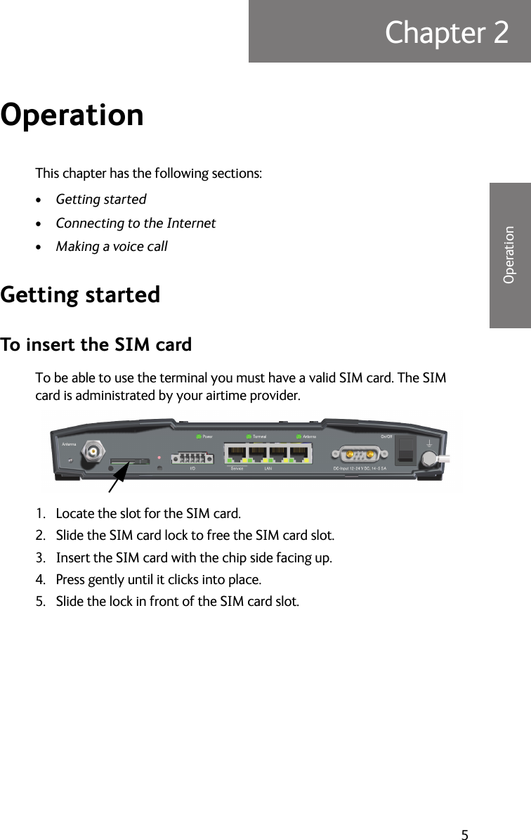
![Chapter 2: Operation8 Getting startedsubscribed mobile number to the SIP user name is fixed. For an example see the following table.See your subscription information for the exact details on which mobile number is assigned to which user name.To connect one or more VoIP-phone or soft-phone (mobile apps, PC software), do as follows:1. In order to use the telephony service connect a SIP or VoIP enabled telephone to a user port of the BDU and register it with the built-in SIP server.2. If a router or wireless access point is used to connect the telephone, make sure that the required protocols for VoIP telephony. You can find a list of these protocols at the end of this chapter.3. For the registration on the BDU a number of network-specific parameters are necessary, which are stored in a "SIP profile" in the telephone. At least configure the following items:Mapping from subscribed mobile numbersUser name Mobile number Line type Voice quality line1 8816xxxxxxx1 PostPaid HQline2 8816xxxxxxx2 PostPaid HQline3 8816xxxxxxx3 PostPaid HQNetwork-specific parametersItem Value DescriptionProfile name [arbitrary] Select a name.User name line1, line2 or line3Select the user name assigned to the mobile phone number that shall be usedPassword [leave empty] No password requiredSIP server 172.16.0.1 This is the default address. If the address does not work contact the administrator for the correct one.](https://usermanual.wiki/Thrane-and-Thrane-A-S/4330A/User-Guide-3891589-Page-20.png)