Thrane and Thrane A S 4330A 404330A User Manual
Thrane & Thrane A/S 404330A
Users Manual
SAILOR 4300 L-Band System
User manual
i
SAILOR 4300 L-Band System
User manual
Document number: 98-159912-A
Release date: 22 May 2018
ii
Disclaimer
Any responsibility or liability for loss or damage in connection with the use of this
product and the accompanying documentation is disclaimed by Thrane & Thrane
A/S. The information in this manual is provided for information purposes only, is
subject to change without notice and may contain errors or inaccuracies. Manuals
issued by Thrane & Thrane A/S are periodically revised and updated. Anyone relying
on this information should acquire the most current version e.g. from
www.cobham.com/satcom, Cobham SYNC Partner Portal, or from the distributor.
Thrane & Thrane A/S is not responsible for the content or accuracy of any
translations or reproductions, in whole or in part, of this manual from any other
source. In the event of any discrepancies, the English version shall be the governing
text.
Thrane & Thrane A/S is trading as Cobham SATCOM.
Manufacturer address
Thrane & Thrane A/S, Industrivej 30, DK-9490, Pandrup, Denmark
Copyright
© 2018 Thrane & Thrane A/S. All rights reserved.
Trademark Acknowledgements
• SAILOR is a registered trademark of Thrane & Thrane A/S in the European Union
and the Unites States of America and other countries.
GPL notification
The software included in this product contains copyrighted software that is licensed
under the GPL/LGPL. The verbatim licenses can be found online at:
http://www.gnu.org/licenses/old-licenses/gpl-2.0.html
http://www.gnu.org/licenses/old-licenses/lgpl-2.1.html
You may obtain the complete corresponding source code from us for a period of
three years after our last shipment of this product, which will be no earlier than 2021,
by sending a money order or check for DKK 50 to:
SW Technology/GPL Compliance,
Cobham SATCOM (Thrane & Thrane A/S),
Lundtoftegaardsvej 93D
2800 Lyngby
DENMARK
iii
Write "source for product SAILOR 4300 L-Band System" in the memo line of your
payment. This offer is valid to anyone in receipt of this information.
http://www.cobham.com/communications-and-connectivity/satcom/free-and-open-
source-software-foss/
Warranties
Any attempt to install or execute software not supplied by Cobham SATCOM on this
device will result in the warranty being void. Any attempt to modify the software on
this device in a way not specified by Cobham SATCOM will result in the warranty
being void.
NOTICE:
This device complies with Part 15 of the FCC Rules [and with Industry Canada
licence-exempt RSS standard(s)]
Operation is subject to the following two conditions:
Le présent appareil est conforme aux CNR d'Industrie Canada applicables aux
appareils radio exempts de licence. L'exploitation est autorisée aux deux conditions
suivantes:
NOTICE:
Changes or modifications made to this equipment not expressly approved by
(manufacturer name) may void the FCC authorization to operate this equipment.
(1) this device may not cause harmful interference, and
(2) this device must accept any interference received, including interference
that may cause undesired operation.
(1) l'appareil ne doit pas produire de brouillage, et
(2) l'appareil doit accepter tout brouillage radioélectrique subi, même si le
brouillage est susceptible d'en compromettre le fonctionnement.
FCC & IC
iv
Safety summary
The following general safety precautions must be observed during
all phases of operation, service and repair of this equipment. Failure
to comply with these precautions or with specific warnings
elsewhere in this manual violates safety standards of design,
manufacture and intended use of the equipment. Thrane & Thrane
A/S assumes no liability for the customer's failure to comply with
these requirements.
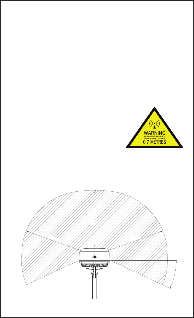
Microwave radiation hazards
During transmission the antenna in this
system radiates Microwave Power.This
radiation may be hazardous to humans
close to the antenna. During transmission,
make sure that nobody gets closer than
the recommended minimum safety
distance.
The minimum safety distance to the antenna is 0.7 m, based on
max Eirp= 46.4dBm +1dB. No hazard exists > 25° below the
antenna’s mounting plane. Refer to the drawing below.
0.7 m
0.7 m
0.7 m
25°

v
Service
User access to the interior of the terminal is not allowed. Only a
technician authorized by Cobham SATCOM may perform service -
failure to comply with this rule will void the warranty. Access to the
interior of the antenna is not allowed. Replacement of certain
modules and general service may only be performed by a
technician authorized by Cobham SATCOM.
Do not operate in an explosive atmosphere
Do not operate the equipment in the presence of flammable gases
or fumes. Operation of any electrical equipment in such an
environment constitutes a definite safety hazard.
Failure to comply with the rules above will void the
warranty!

vi
Preface
Approvals and standard compliance
The SAILOR 4300 L-Band System is approved according to RED
2014/53/EU and FCC part 25. The approvals of the SAILOR
4300 L-Band System are constantly monitored. New national
approvals will be applied for and granted and new test standards
may come into force. Therefore the above list may not be
complete. Contact your authorized dealer for more information.
About the manual
Intended readers
This manual is a user manual for the SAILOR 4300 L-Band
System. This manual is intended for anyone who is using or
intends to use this system. No specific skills are required to
operate the SAILOR 4300 L-Band System. However, it is
important that you observe all safety requirements listed in the
beginning of this manual, and operate the system according to
the guidelines in this manual. Note that this manual does not
cover installation of the system. For information on installation
refer to the installation manual. Part numbers for related
manuals are listed in the next section.

Chapter :
vii

Chapter :
viii

1
Table of contents
Chapter 1 Introduction
General description ..............................................................................1
Overview ............................................................................................................... 1
SAILOR 4338A Below Deck Unit (BDU) ................................................. 1
SAILOR 4352A Above Deck Unit (ADU) ................................................ 1
Data sessions and voice calls ...................................................................... 2
IMEI and IMSI number .................................................................................. 3
Part numbers ...........................................................................................3
Chapter 2 Operation
Getting started .......................................................................................5
To insert the SIM card ................................................................................... 5
Power on ............................................................................................................... 6
To connect a PC and SIP phone ................................................................ 7
Connecting to the Internet ..........................................................10
Mobile web interface ....................................................................................10
Start a data session ........................................................................................11
Making a voice call ............................................................................ 12
Call from the terminal ..................................................................................12
Call to the terminal ........................................................................................12
Chapter 3 Service & maintenance
Maintenance ........................................................................................13
Contact for support .......................................................................................13
Status information in the mobile web interface .............................14
Troubleshooting .................................................................................15
Introduction ......................................................................................................15
Light indicators ................................................................................................15
BITE events (warning sign) ........................................................................19
To restart the terminal .................................................................................23
Service and repair .............................................................................. 24
Disposal ...............................................................................................................24

Table of contents
2
App. A Specifications
SAILOR 4300 L-Band System ...................................................... 25
Glossary .....................................................................................................................29
Index .....................................................................................................................31
1
Chapter 1
11111
Introduction
Introduction 1
This chapter contains the following sections:
•General description
•Part numbers
General description
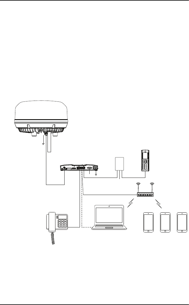
Overview
The SAILOR 4300 L-Band
System consists of an ADU
(Above Deck Unit) and a
BDU (Below Deck Unit). The
two units are connected with
a single coax cable with TNC
female connectors. The
system is DC powered. The
SAILOR 4300 L-Band System
is used for voice calls and
data sessions.
Data rates and coverage
Iridium OpenPort Services offer up to 134/134 kbps, while Iridium Certus
350 Services offer up to 176/352 kbps. Iridium has 100% global coverage.
Some countries may have national restrictions.
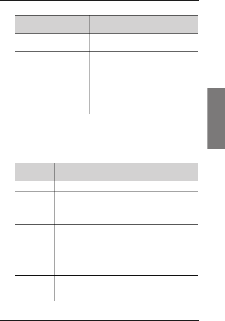
SAILOR 4338A Below Deck Unit (BDU)
The BDU is the central unit in the system. It contains all user interfaces and
handles all communication between the ADU and the local communication
units (phones, computers etc.).
SAILOR 4352A Above Deck Unit (ADU)
The ADU consists of an antenna with an RF-unit, unit for antenna control
and GPS antenna. The ADU is dedicated to the Iridium system.
Chapter 1: Introduction
2 General description
Data sessions and voice calls
The SAILOR 4300 L-Band System provides up to 3 simultaneous IP voice
calls or 3 data sessions or a combination thereof with a maximum of 3
connections in total.
The BDU has three user ports for user data traffic. A data session can be
activated automatically at start-up or manually. The BDU has a DHCP server
with a configurable start/end range of IP addresses for user devices. Also it
includes port forwarding with up to 8 configurable forwarding rules for UDP
and TCP protocols.
The BDU communicates directly with SIP phones on any of the three LAN
user ports (LAN 2, 3 or 4).
To set up a VoIP phone see To connect a PC and SIP phone on page 7.
Power
Terminal
Antenna
Power
I/O
LAN
Service
Reset
Antenna
DC-Input 12-24 VDC; 14-5.5 A
SIM-Card
12-24 VDC
Below Deck Unit
Above Deck Unit
TT-4338A
TT-4352A
cable
- Installation on bigger vessels: RG214/U up to 100 m length
Connector type: TNC
- Installation in a mechanically protected environment and shorter distances: RG223/U up to 25 m length
Cable requirements:
*
WLAN
Wireless SIP Phones
Wired IP Handset
Notebook
Power
PoE adapter
SIP Phone
Recommended
*
Chapter 1: Introduction
Part numbers 3
11111
Introduction
IMEI and IMSI number
The terminal has an IMEI number which is stored by Iridium. The IMEI is
printed on the BDU type label. The IMSI number is printed on the SIM card
which you have received from your airtime provider.
Part numbers
This manual is for the SAILOR 4300 L-Band System and is applicable to the
following part numbers:
Part number Description
404338A-00500 SAILOR 4338A Below Deck Unit (Bulk)
404338A-00510 SAILOR 4338A Below Deck Unit (19” rack)
404352A-00500 SAILOR 4352A Above Deck Unit

Chapter 1: Introduction
4 Part numbers
5
Chapter 2
22222
Operation
Operation 2
This chapter has the following sections:
•Getting started
•Connecting to the Internet
•Making a voice call
Getting started
To insert the SIM card
To be able to use the terminal you must have a valid SIM card. The SIM
card is administrated by your airtime provider.
1. Locate the slot for the SIM card.
2. Slide the SIM card lock to free the SIM card slot.
3. Insert the SIM card with the chip side facing up.
4. Press gently until it clicks into place.
5. Slide the lock in front of the SIM card slot.
Chapter 2: Operation
6 Getting started
Power on
Depending on which of the three possible power switch configurations is
installed on the ship, the product is powered up as follows:
• Using the on/off switch in the front panel of the SAILOR 4338A Below
Deck Unit (bulk), see the following table.
• Using the on/off switch on the SAILOR 4338A Below Deck Unit (19"
rack), see the following table.
• Using a remote on/off control (2 pin input in the Sub-D input
connector). See the two tables above.
In the following sections only normal BDU configuration is shown. The
terminal is DC powered (10-32 VDC).
Power on/off Front Switch Remote switch
OFF OFF Not Used
OFF ON Make
ON ON Not Used
ON ON Break
Power on/off Front Switch Rack Switch Remote switch
OFF OFF x x
OFF ON OFF Make
OFF ON ON Make
OFF ON OFF Not Used
OFF ON OFF Break
ON ON ON Not Used
ON ON ON Break
Chapter 2: Operation
Getting started 7
22222
Operation
To power up the system, do as follows:
1. Power up the system, i.e. switch on the terminal.
2.
3. Wait until the LEDs at the rear of the terminal show that the system is
ready to be accessed.
• Power LED: Green
• Terminal: Steady green.
• Antenna: Steady green.
4. The system is ready for use.
To connect a PC and SIP phone
Connect your equipment to the Ethernet connector(s) marked LAN. You
need a straight LAN cable.
SIP telephony service
The SAILOR 4300 L-Band system has a built-in SIP server which provides up
to three voice lines to users connected to the BDU. To use this service you
need one or more VoIP-phone or soft-phone (mobile apps, PC software).
The effective number of available voice lines depends on the subscription.
Each voice line has a dedicated mobile number and is available through one
of the internal SIP user names line1, line 2 and line3. The mapping from
Note The first couple of seconds there is not light in the Power LED.
Wait until there is light in the Power LED.
Chapter 2: Operation
8 Getting started
subscribed mobile number to the SIP user name is fixed. For an example see
the following table.
See your subscription information for the exact details on which mobile
number is assigned to which user name.
To connect one or more VoIP-phone or soft-phone (mobile apps, PC
software), do as follows:
1. In order to use the telephony service connect a SIP or VoIP enabled
telephone to a user port of the BDU and register it with the built-in SIP
server.
2. If a router or wireless access point is used to connect the telephone,
make sure that the required protocols for VoIP telephony. You can find a
list of these protocols at the end of this chapter.
3. For the registration on the BDU a number of network-specific
parameters are necessary, which are stored in a "SIP profile" in the
telephone. At least configure the following items:
Mapping from subscribed mobile numbers
User name Mobile number Line type Voice quality
line1 8816xxxxxxx1 PostPaid HQ
line2 8816xxxxxxx2 PostPaid HQ
line3 8816xxxxxxx3 PostPaid HQ
Network-specific parameters
Item Value Description
Profile name [arbitrary] Select a name.
User name line1, line2 or
line3
Select the user name assigned to the
mobile phone number that shall be
used
Password [leave empty] No password required
SIP server 172.16.0.1 This is the default address. If the
address does not work contact the
administrator for the correct one.
Chapter 2: Operation
Getting started 9
22222
Operation
You can use all available mobile numbers and user names from within one
telephone or application. That means that you can handle all your
subscribed numbers from one device. Note that not all devices might
support subscribing to more than one line. See the device's user manual for
details.
Suitable telephones for this service are dedicated stand-alone VoIP-, IP- or
SIP-telephones, or soft-phone applications running on a PC or mobile
phone. A VoIP-app on a mobile phone can only be used if the phone is
connected to the device via a separate wireless router. Any modern SIP-
telephone or software are suited for use with the SAILOR 4300 unit, though
this cannot be guaranteed for a specific type of device or software.
At least the following protocols and codecs must be supported:
Note For details of how to configure your device consult the
telephone's user manual.
Important You cannot register more than one telephone on the same
mobile number respective user name on the SIP-server. If
more telephones register with the same SIP-profile, only the
last telephone registered will be subscribed to the mobile
number and be able to use this number for receiving and
making calls.
Protocols and codes
Item Name Description
SIP protocol SIP protocol version 2.0; internet standard RFC
3261
SDP protocol Internet standards RFC 2327 and RFC 3264
RTP - voice streams Internet standard RFC 1889 or RFC 3550
Voice stream format G.711 A-law; 8000 Hz sampling rate; packet
interval 20 ms
DTMF format Internet standard RFC 4733
Chapter 2: Operation
10 Connecting to the Internet
Connecting to the Internet
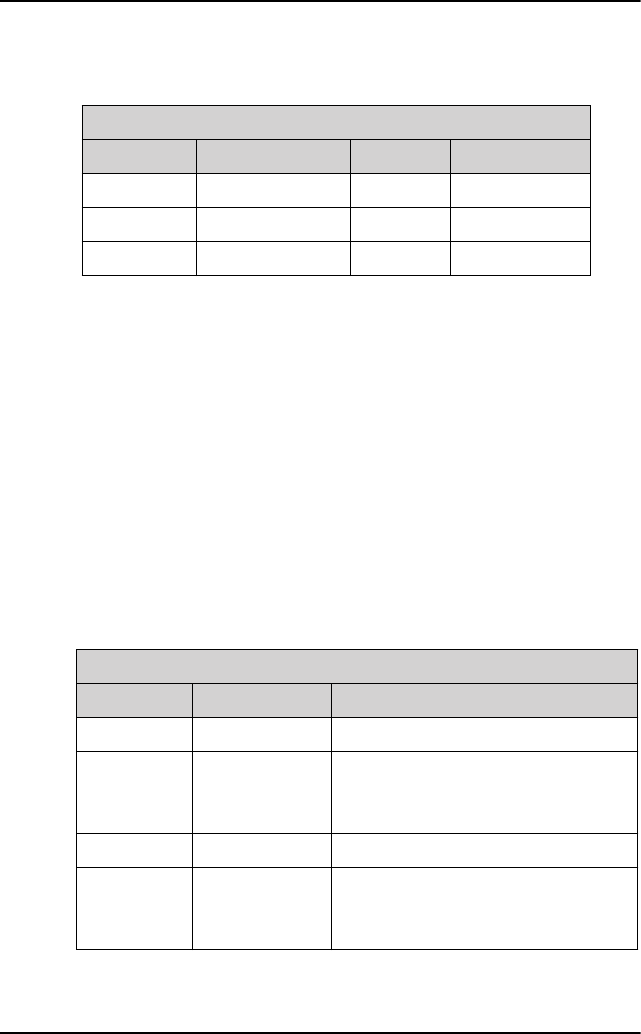
Mobile web interface
The purpose of the mobile web
interface is to use the SAILOR
4300 L-Band System for starting
and stopping data sessions and
view system events. To access
the mobile web interface use a
smartphone or tablet that is
connected to the terminal via
the user LAN ports. The mobile
web interface is intended for
users of mobile devices. It
consists of a subset of the
functions in the classic web
interface The mobile web
interface is available on the user
LAN ports.
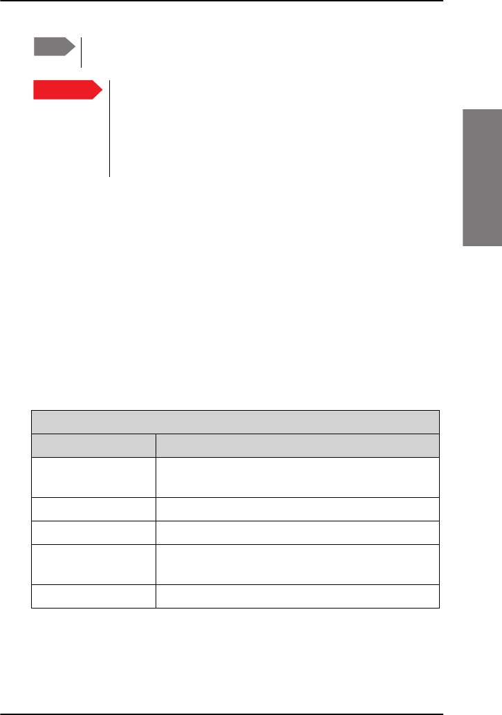
Connecting to the mobile web interface
To connect to the mobile web interface, do as follows:
1. Connect a computer to one of the user LAN ports (standard Ethernet) or
through a smartphone via WLAN.
2. Open your Internet browser and enter
the IP address of the BDU User LAN
http://172.16.0.2 (default).
3. Enter the user name: guest, password:
guest.
Tap here
for menu
s
available.
Chapter 2: Operation
Connecting to the Internet 11
22222
Operation
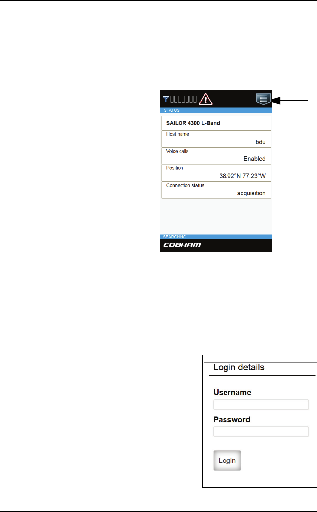
Menus in the mobile web interface
The mobile web interface has the
following top-level menus:
•Status shows information such as
system status, host name, position,
statistics etc.
•Data for start or stop of a data session
(if Data Mode is set to Manual during
installation).
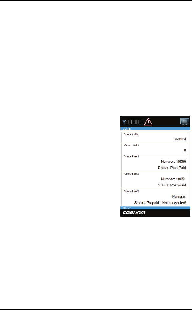
•Voice displays the status of voice calls
•Event list shows a list of currently
active events (if any).
•Help opens this manual in a pdf
version.
•Logout
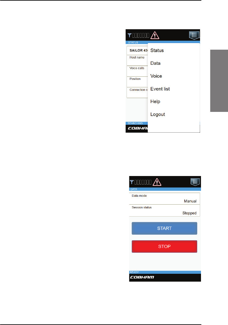
Start a data session
To be able to access the Internet you must
have an active data session.
To start a data session manually, do as
follows:
1. Open your Internet browser and enter
the default IP address of the BDU User
LAN http://172.16.0.2 (default).
2. Tap the menu icon and select Data to
start or stop a data session.
Chapter 2: Operation
12 Making a voice call
Making a voice call
Call from the terminal
To make a call from a phone connected to the SAILOR 4300 L-Band
System:
Example: To call Cobham SATCOM in Denmark: (+45 39558800): dial 00
<country code> <phone number> followed by press on call:
00 45 39558800 #.
Call to the terminal
You find the voice numbers for your
terminal in your airtime subscription. To
make a call to a phone connected to the
SAILOR 4300 L-Band System:
Dial +<Iridium mobile number>
(+ is the prefix to call out of the country
you are located in).

13
Chapter 3
33333
Service & maintenance
Service & maintenance 3
This chapter has the following sections:
•Maintenance
•Troubleshooting
•Service and repair
Maintenance
Maintenance of the SAILOR 4300 L-Band System can be reduced to a
maintenance check at each visit of the service staff. Inspect the unit for
mechanical damages, salt deposits, corrosion and any foreign material. Due
to its robust construction and ruggedness the unit has a long lifetime.
Anyway it must carefully be checked at intervals not longer than 12 months
– dependent on the current working conditions.
Contact for support
Contact an authorized dealer for technical service and support of the
SAILOR 4300 L-Band System. Before contacting the authorized dealer you
can go through the troubleshooting guide to solve some of the most
common operational problems.
Chapter 3: Service & maintenance
14 Maintenance
Status information in the mobile web interface
To display Status information in the mobile web interface, do as follows:.
1. Open the mobile web interface on your
device.
2. The current status is displayed.
In case a warning sign is displayed, you can
tap on it to display the current system
events.
The overall state of the system is always
displayed at the bottom of the mobile web
interface. The following states are shown:
• INITIALIZING. The system is
initializing itself.
• SELF TESTING. Self test is performed
after start up.
• READY. The system is ready for
operation.
• SEARCHING. The system is searching
for available satellites.
• SIGNAL AVAILABLE. Satellite signal is
available from at least one candidate
satellite. Ready to connect.
• CONNECTED. The system is registered and connected to the satellite
network. Ready to use.
• DENIED. Registration on the network was denied. The denial cause will
appear on the status page. Check also SIM card status matches the
requested service.
Chapter 3: Service & maintenance
Troubleshooting 15
33333
Service & maintenance
• OVERHEATING. System is overheated. System is halted in 30 seconds
• ERROR. A critical error is detected. See event list.
The latest version of this manual is available in PDF format via the HELP
menu. The manual will either be displayed immediately or it will be available
in the download folder (depending on the browser or mobile device used).
Troubleshooting
Introduction
In this section you find possible root causes to the experienced errors and
suggestions for a remedy. Listed are only errors that may be caused by
wrong installation, wrong configuration or misuse of the product. Errors
where no remedy is listed could indicate damaged equipment. If failing to
restore normal system status contact your service partner. The following
sources for system validation are available:
•Light indicators
•BITE events (warning sign)
Light indicators
The BDU terminal has several indicator LEDs. They indicate the overall
system status during normal use.
Chapter 3: Service & maintenance
16 Troubleshooting
Power LED
Terminal LED
The terminal LED shows the status of the BDU, ADU and BCX
(Iridium module). In case of an error (red), this could be an error in
the BDU, ADU or BCX.
Indicator
pattern State Remedy
Off Power off Check if power is present. See section Power
on on page 6.
On (Green) Power on Normal operation.
Indicator
pattern State Remedy
Off Power off Check if power is present.
Blue System
initialization
The BDU initializes and powers the ADU.
The system waits until a successful
connection between BDU and ADU has
been established.
Green flashing Self-test
(BDU and
ADU POST)
The terminal and antenna is not yet ready
(while performing Power On Self Test). This
state may remain for approximately
60 seconds (it is not an error).
If the state persists restart the system.
Yellow steady Warning User
recoverable
User recoverable continuous warning event
detected, see active BITE event in the web
interface as described in the section BITE
events (warning sign) on page 19.
Chapter 3: Service & maintenance
Troubleshooting 17
33333
Service & maintenance
Antenna LED
The antenna LED shows the status of the ADU and the Iridium link
connection. In case of an error (red), it could be an error in the ADU
or BCX (Iridium modem).
Green steady Terminal
ready
The terminal is operational and ready for
use.
Red steady Error (BDU,
ADU or BCX)
A fatal error is detected in the system.
If possible, read out the event list.
If a critical temperature is detected
(overheating in the BDU) the product may
be restarted after cooling has been
provided. On other failures see the section
BITE events (warning sign) on page 19 or
contact your service partner.
Indicator
pattern State Remedy
Indicator
pattern Meaning Remedy
Off Power off Check if power is present.
Blue steady Initializing
(ADU/BCX
start-up and
self-tests)
The antenna is not yet ready. This state
may remain for approximately 120
seconds (this is not an error). If the state
persists restart the unit).
Yellow flashing Searching Normal system state, see Status
information in the mobile web interface
on page 14.
Green flashing Signal available Normal system state, see Status
information in the mobile web interface
on page 14.
Green steady Connected Normal system state, see Status
information in the mobile web interface
on page 14.
Chapter 3: Service & maintenance
18 Troubleshooting
Ethernet LEDs
The Ethernet RJ45 connectors have two LEDs built-in, Green and
Yellow.
Yellow steady Denied Service is denied on the Iridium network.
Check SIM card status matches the
requested service.
Red steady Error (ADU or
BCX)
A fatal error is detected in the system.
See active BITE POST event in the web
interface as described in the section BITE
events (warning sign) on page 19.
Indicator
pattern Meaning Remedy
Indicator
pattern Meaning Green - Remedy
Off Power off or
10 Mbps
Check the LAN cable connection to PC or
handsets. Check that handsets are not
connected to the service port (left most).
On 100 Mbps Normal.
Indicator
pattern Meaning Yellow - Remedy
Off Power off or
no link pulse
Check LAN cable connection to PC or
handsets. Check that handsets are not
connected to the service port (left most).
On steady Link Normal
Flashing Traffic Normal

Chapter 3: Service & maintenance
Troubleshooting 19
33333
Service & maintenance
BITE events (warning sign)
BITE events are shown in the event list. The following table shows
suggestions how to deal with the events.
BITE ID
(HEX)
System component
symptom Remedy
8301
8302
ADU GPS module has
no connection
ADU GPS module has
no fix
Restart the terminal and see
below.
Inspect the ADU and check all
cables.
Compare position shown on
Status page with vessel’s main
GPS.
8401
8402
ADU Temperature
above warning level
ADU Temperature
above critical level
The system will automatically
decrease the transmit
performance on temperature
warnings.
On detection of critical
temperatures the system will
protect itself by powering off the
ADU. After a cool down period
(30 minutes) the system will
automatically restart.
8403
8404
8405
8406
8407
8408
8409
840A
ADU internal voltage
errors.
Contact your service partner.

Chapter 3: Service & maintenance
20 Troubleshooting
840B
840C
ADU PSU temperature
above warning level
ADU PSU temperature
above critical level
The system will automatically
decrease the transmit
performance on temperature
warnings.
On detection of critical
temperatures the system will
protect itself by powering off the
ADU. After a cool down period
(30 minutes) the system will
automatically restart.
840D
840E
ADU Antenna switch
temp. above warning
level
ADU Antenna switch
temp. above critical
level.
The system will automatically
decrease the transmit
performance on temperature
warnings.
On detection of critical
temperatures the system will
protect itself by powering off the
ADU. After a cool down period
(30 minutes) the system will
automatically restart.
8501 No communication to
Iridium modem (BCX)
Restart the terminal (see below).
8502 Iridium modem (BCX)
critical fault detected
Restart the terminal (see below).
8503 High power amplifier
control fault detected
Restart the terminal.
If persistent contact service
partner
BITE ID
(HEX)
System component
symptom Remedy
Chapter 3: Service & maintenance
Troubleshooting 21
33333
Service & maintenance
8601
8602
HPA Temperature
above warning level
HPA Temperature
above critical level
The system will automatically
decrease the transmit
performance on temperature
warnings.
On detection of critical
temperatures the system will
protect itself by powering off the
ADU. After a cool down period
(30 minutes) the system will
automatically restart.
8A01 ADU boot-up problem.
System services may be
not available.
Restart the terminal (see below).
8C01 ADU GPS module has
no connection
Restart the terminal (see below).
8D01
8D02
8D03
8D04
8D05
ADU integrity check
and configuration check
failure.
Restart the terminal (see below).
Contact your service partner and
await instructions for reporting.
9001 BDU ADU
communication check
error
Inspect antenna cable
connection between BDU and
ADU.
Restart the terminal (see below).
BITE ID
(HEX)
System component
symptom Remedy

Chapter 3: Service & maintenance
22 Troubleshooting
9002
9003
BDU temperature above
warning level
BDU temperature above
critical level
On temperature warnings try to
provide sufficient ventilation to
the terminal (opening lockers,
check fans, etc.).
On detection of critical
temperatures the system will halt
completely after 30 seconds.
Manual restart is required after
cooling has been provided.
900
9005
9006
9007
9008
9009
900A
BDU Internal voltage
errors.
Contact your service partner.
900C
900D
BDU PSU temperature
above warning level
BDU PSU temperature
above critical level
(System will enter a
protection state)
On temperature warnings try to
provide sufficient ventilation to
the terminal (opening lockers,
check fans, etc.).
On detection of critical
temperatures the system will halt
completely after 30 seconds.
Manual restart is required after
cooling has been provided.
900E BCX firmware mismatch Contact your service partner.
9101 BDU SIM card reader
empty. No service
Insert a valid SIM card.
9102 BDU cannot connect to
the Iridium modem
(BCX)
Restart the terminal (see below).
Contact your service partner.
BITE ID
(HEX)
System component
symptom Remedy

Chapter 3: Service & maintenance
Troubleshooting 23
33333
Service & maintenance
To restart the terminal
To restart the terminal, power-cycle it, see Power on on page 6.
9601 BCX reports a reboot. Observe the number of this
event and report the event, if
persistent, to your service
partner.
9602
9603
BCX temperature above
warning level
BCX temperature above
critical level
The system will automatically
decrease the transmit
performance on temperature
warnings.
On detection of critical
temperatures the system will
protect itself by powering off the
ADU. After a cool down period
(30 minutes) the system will
automatically restart.
9801, 9802 BDU integrity check and
configuration check
failure.
Restart the terminal (see below).
Contact your service partner and
await instructions for reporting.
9901 BDU SIM module reader
error
Contact your service partner.
9902 Iridium modem (BCX)
self-check error
Contact your service partner.
9903 Iridium modem (BCX)
reports wrong antenna
type configuration
Contact your service partner.
9A01 BDU boot-up problem.
System services may be
not be available
Restart the terminal (see below).
BITE ID
(HEX)
System component
symptom Remedy

Chapter 3: Service & maintenance
24 Service and repair
Service and repair
Should your Cobham SATCOM product fail, please contact your dealer or
installer, or the nearest Cobham SATCOM partner. You will find the partner
details on www.cobham.com/satcom, Technical Service Partner List.
You can also access the Partner Portal at www.cobham.com/satcom,
Cobham SYNC Partner Portal, which may help you solve the problem.
Your dealer, installer or Cobham SATCOM partner will assist you whether
the need is user training, technical support, arranging on-site repair or
sending the product for repair. Your dealer, installer or Cobham SATCOM
partner will also take care of any warranty issue.
Applicable SAILOR part numbers
See Part numbers on page 3.
Disposal
Old electrical and electronic equipment marked with this
symbol can contain substances hazardous to human beings
and the environment. Never dispose these items together
with unsorted municipal waste (household waste). In order to
protect the environment and ensure the correct recycling of
old equipment as well as the re-utilization of individual
components, use either public collection or private collection by the local
distributor of old electrical and electronic equipment marked with this
symbol.
Contact the local distributor for information about what type of return
system to use.
25
Appendix A
AAAAA
Specifications
Specifications A
SAILOR 4300 L-Band System
Item Specification
Weight, BDU 3.5 kg
Weight, BDU, 19” 3.8 kg
Weight, ADU 8 kg
Dimensions, BDU 48 x 27 x 4 cm
Dimensions, BDU, 19” 48 x 49 x 4 cm
Dimensions, ADU ø=38 cm, H=37 cm
Minimum safety distance 0.7 m
APPROVALS
Iridium NEXT approved. Compliant to RED, CE Marked. Tested to FCC part 25
FREQUENCY BAND
Operating frequency range 1616 - 1626.5 MHz
Number of channels 30 sub bands + 0.5 MHz paging
Channel spacing 333.333 kHz
Output power 15.4 dBw
Bandwidth 41.667 kHz, 83.333 kHz, 333.333 kHz,
666.666 kHz
ITU Emission Designator 41K7Q1W,83K3Q1W,333KQ1W,333KQ7W,66
6KQ7W
Type of radio transmission Frequency divide and multi carrier

Appendix A: Specifications
26 SAILOR 4300 L-Band System
Types of modulation QPSK, 16APSK, SE-QPSK multi carrier
Number of antennas 7
Antenna gain 8.7 dB
RECOMMENDED ANTENNA CABLE
Recommended antenna cable RG214U up to 100 m
Requirements for antenna cable <10 dB loss at 80 MHz. Max. 1.8 Ohm DC loop
resistance
POWER SUPPLY AND CONSUMPTION
Voltages 10.8 V to 31.2 VDC
Power consumption (max) 120 W @ 10.8-31.2 VDC
Heat dissipation for BDU 15 W max.
Current consumption Approx. 4Aavg/15Apeak at 12VDC,
2Aavg/8Apeak at 24VDC
ENVIRONMENTAL CONDITIONS
Operating temperature -25 to +55°C
Storage temperature -35 to +85°C
Survival temperature (power on,
non functional)
-35 to +80°C
Automatic thermal surveillance shuts down system gradually in ease of own
temperature
BDU operating humidity 5% to 95% non-condensing at +40°C
ADU enclosure IPX6
ADU operating humidity 5% to 95%
Exposed according to EN 60945
BDU enclosure IP31
Icing (survival) Max 25 mm
Item Specification
Appendix A: Specifications
SAILOR 4300 L-Band System 27
AAAAA
Specifications
VIBRATION (ADU)
Vibration, operational Random spectrum 1.05 g rms x 3 axes: 5 to 20
Hz: 0.02 g2/Hz 20 to 150 Hz:
-3 dB/octave
Vibration, non-operational Random spectrum 1.7 g rms 2 h x 3 axes (6 h
total): 5 to 20 Hz: 0.05 g2/Hz, 20 to 150 Hz: -3
dB/octave
SHIP MOTION
Roll +/- 30 deg. per 4 s, max. 0.7 g tan.
Pitch +/- 15 deg. per 3 s, max. 0.6 g tan.
Yaw +/- 10 deg. per 5 s, max. 0.3 g tan.
Surge +/- 0.5 g
Sway +/- 0.5 g
Heave +/- 0.7 g
Turning rate +/- 36°/s; ACC 12°/s²
Headway speed 22 m/s (42 knots)
Wind 200 km/hr (100 knots)
MECHANICAL SHOCK
Mechanical shock 20g/11 half-sine
ANTENNA CONNECTOR
ADU TNC, female
BDU TNC, female
OTHER SPECIFICATIONS
Standard IP data rate, up/down 176/352 kbps
Ethernet/LAN 4 ports
I/O connector 1 connector
Item Specification

Appendix A: Specifications
28 SAILOR 4300 L-Band System
Status LED Full status LED panel
SIM card slot 1 SIM card slot for Iridium SIM card
Item Specification

29
Glossary
BBBBB
Glossary
Glossary B
A
ADU Above Deck Unit
B
BDU Below Deck Unit
G
GPL General Public License
GPL General Public License, software license, which guarantees
individuals, organizations and companies the freedom to use,
study, share (copy), and modify the software.
L
LGPL Lesser General Public License
P
PSU Power Supply Unit

Glossary
30


Index
32

98-159912-A.03
www.cobham.com/satcom