Thrane and Thrane A S 6222 SAILOR 6222 VHF DSC class A for GMDSS User Manual AdvancedVHF
Thrane & Thrane A/S SAILOR 6222 VHF DSC class A for GMDSS AdvancedVHF
UserManual.wiki
>
Thrane and Thrane A S
>
6222 User Manual
user manual
Navigation menu
Upload a User Manual
Namespaces
Wiki Guide
HTML
PDF
Info
Views
User Manual
Discussion / Help
Navigation

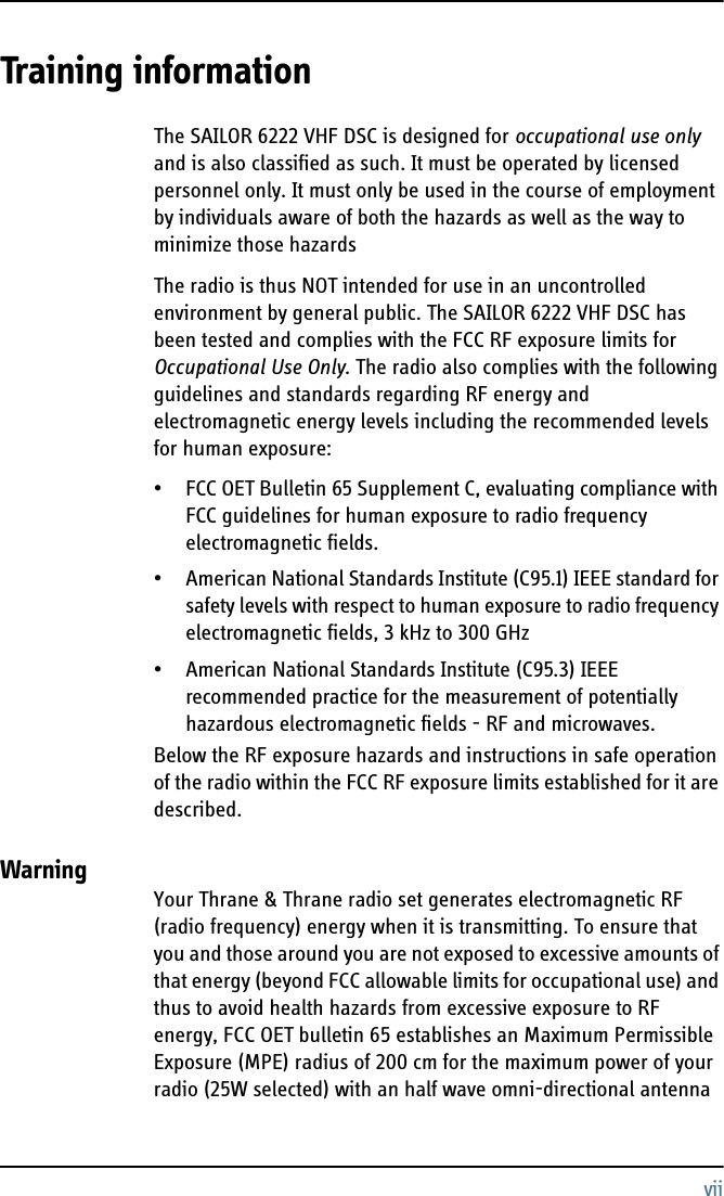

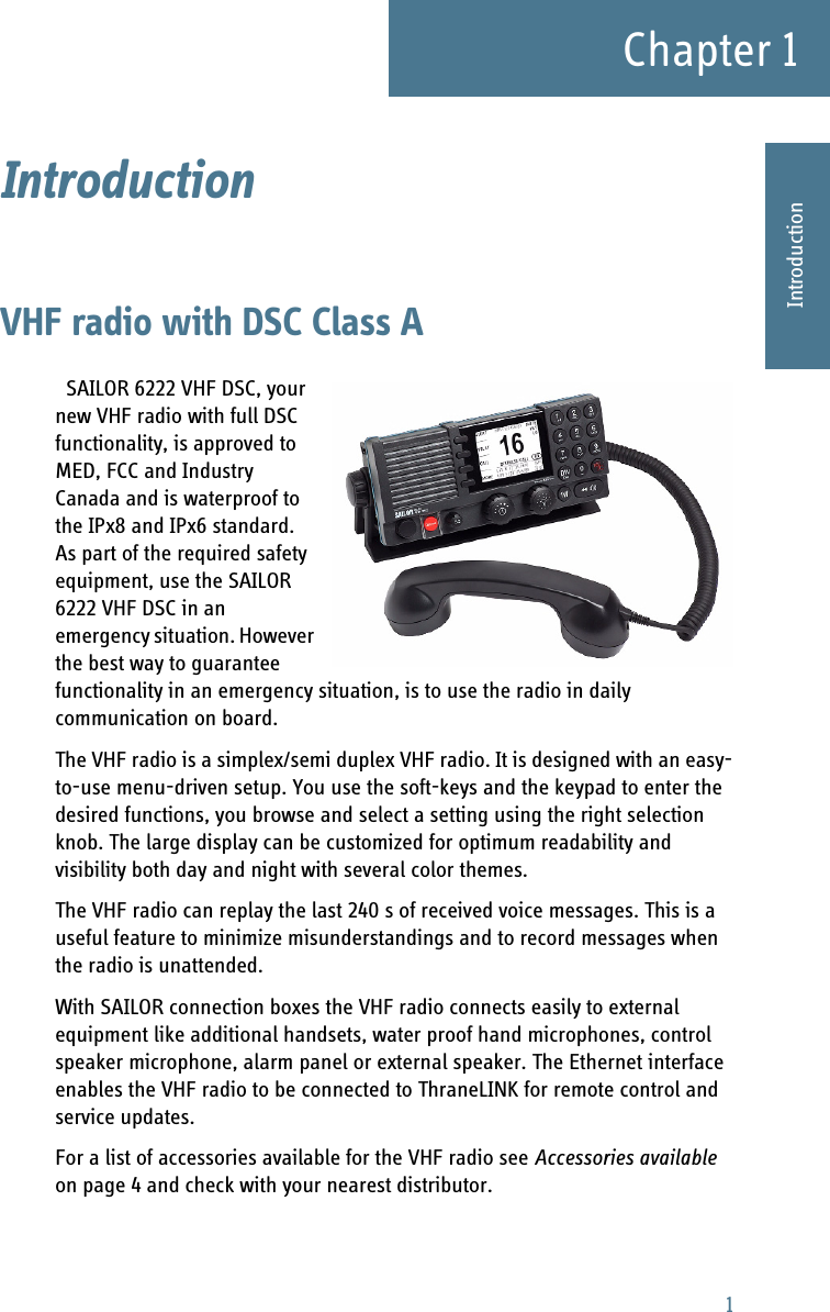
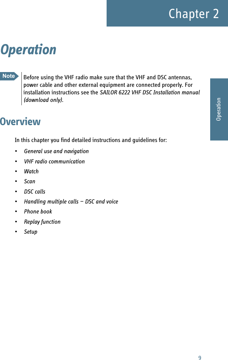
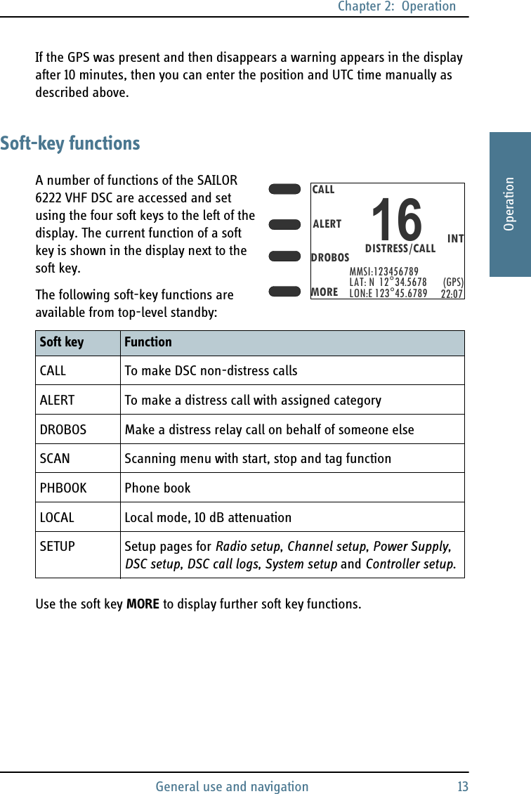
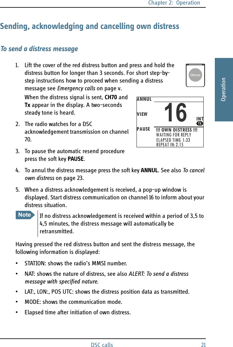
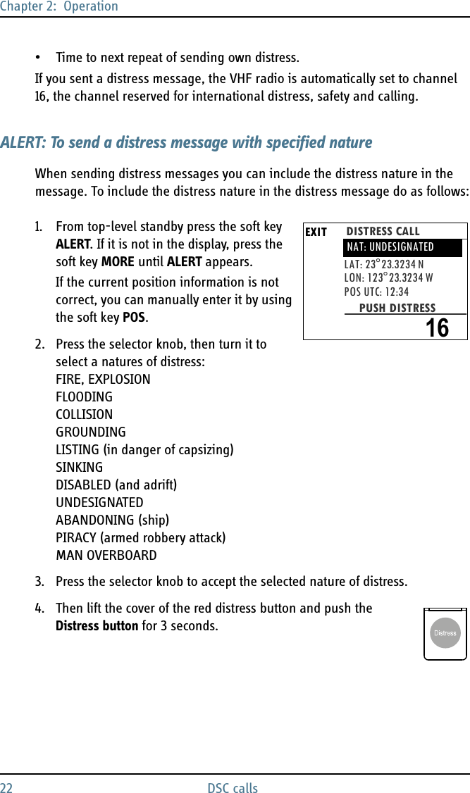
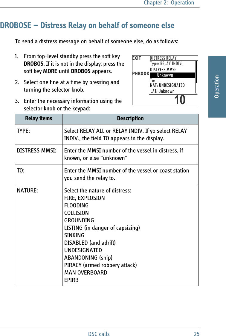
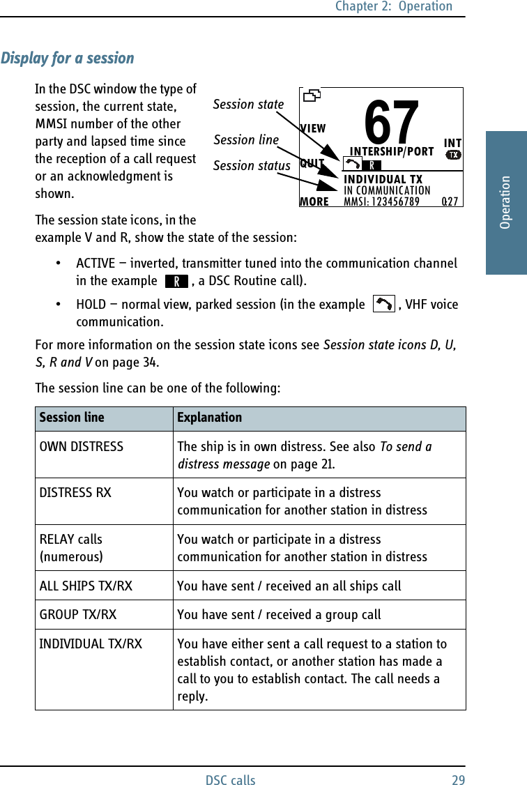
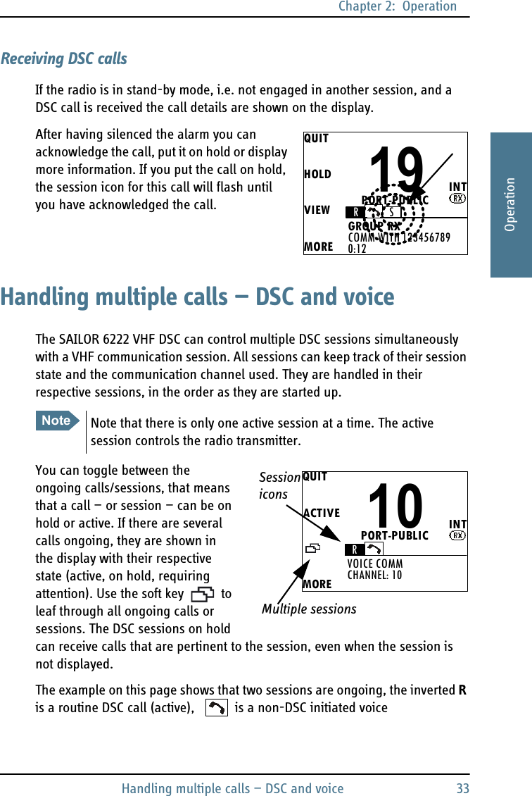
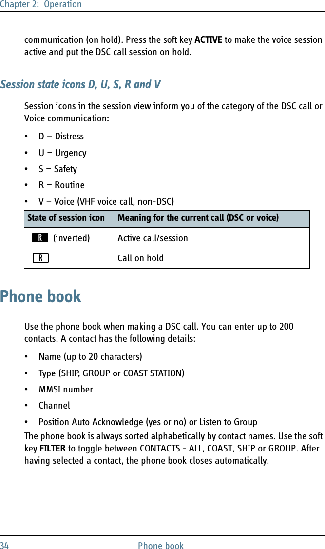
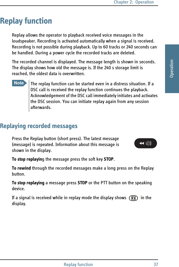
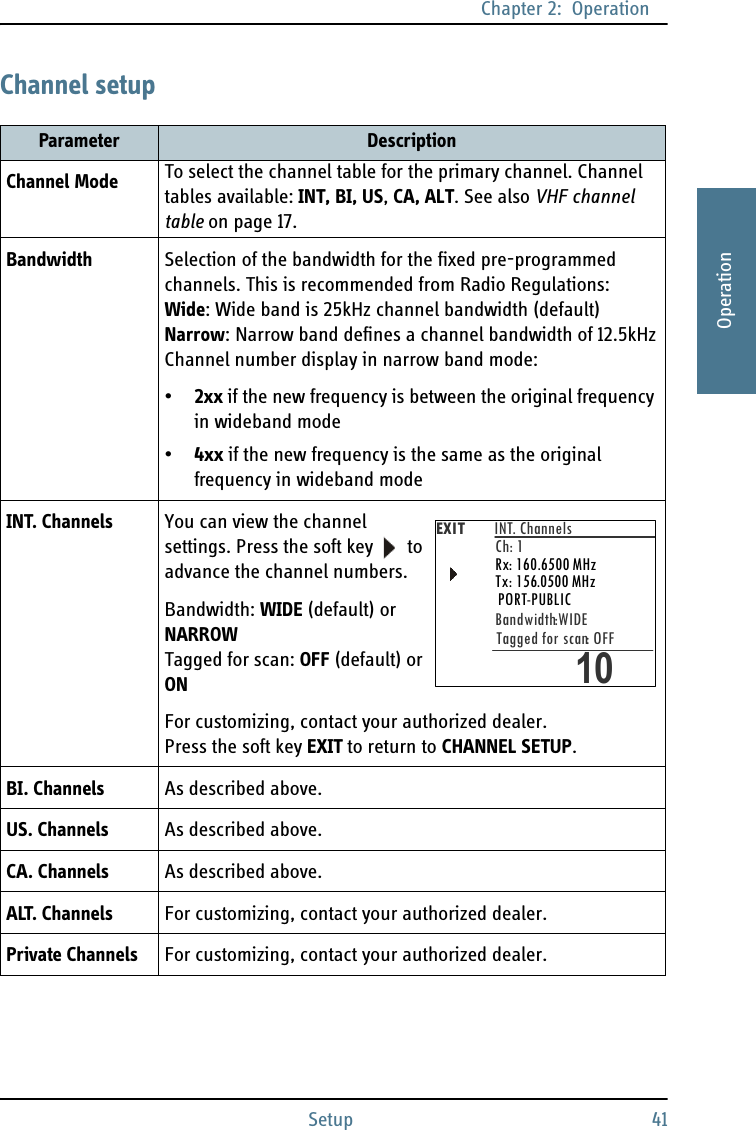
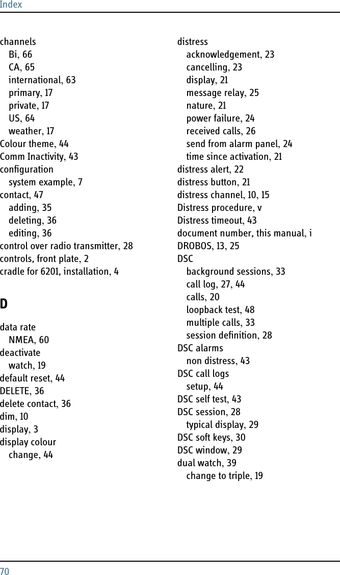
![Chapter 2: OperationVHF radio communication 152222OperationVHF radio communicationBasic VHF operationYou can make VHF calls using the Handset or another speaker device.Quick guide to radio telephone calls1. Press the PTT button on the speaker device. When the TX indicator lights up in the display, the transmission is active.2. To enable reception of a radio signal release the PTT button.Receiving a radio telephone call on channel 16When you hear your call name in the loudspeaker, proceed as follows:1. The symbol RX shows that the radio is receiving on the channel displayed.2. Lift the Handset or take another speaker device.3. Press the PTT button. The symbol TX shows that the radio is transmitting on the channel displayed.4. Repeat the name of the station calling you and say: “This is [your ship’s name]”.NoteA single, short press on the 16/C key always brings you to channel 16, the international calling and distress channel, no matter what state the radio is in.NotePress PTT only when you are talking. Always say “Over.” just before releasing the PTT button.One transmission is limited to 5 minutes duration.TXRXCALLALERTDROBOSMOREMMSI:123456789INTDISTRESS/CALL16LAT: N 12°34.5678LON:E 123°45.6789 (GPS)22:07](https://usermanual.wiki/Thrane-and-Thrane-A-S/6222/User-Guide-1487844-Page-27.png)
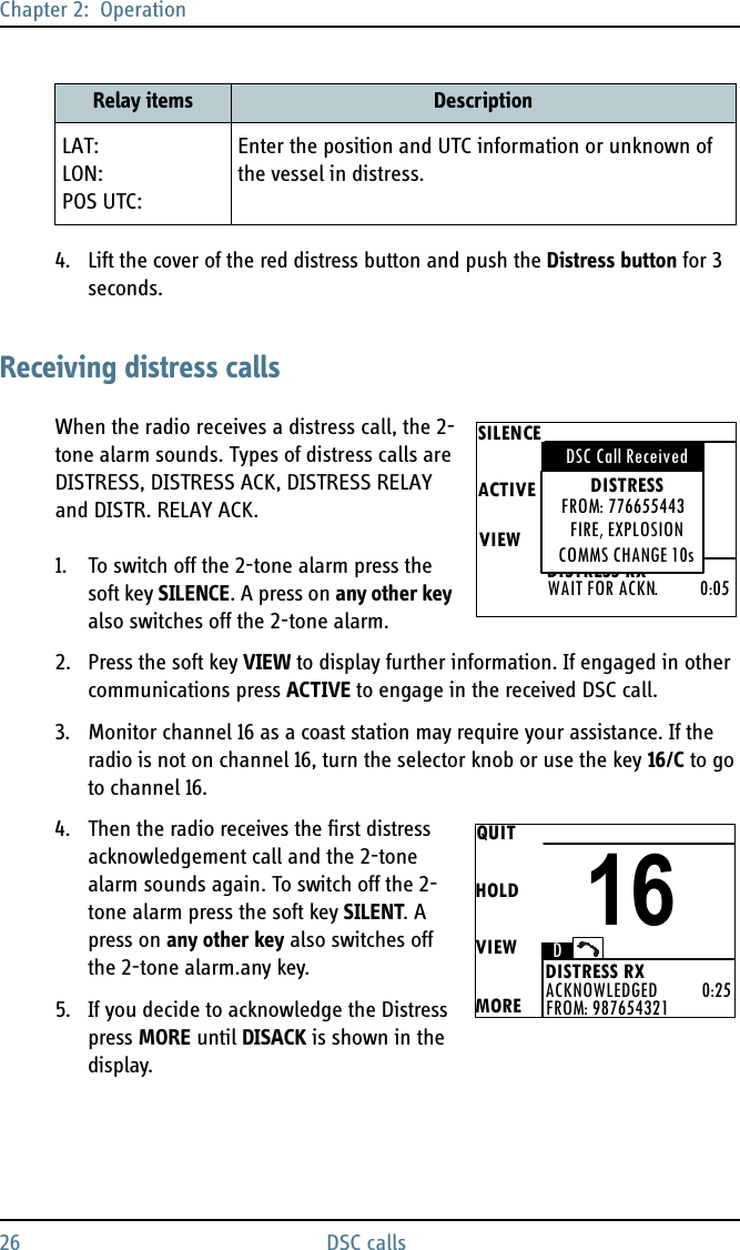
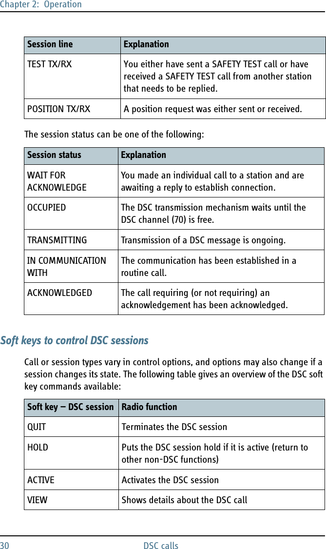
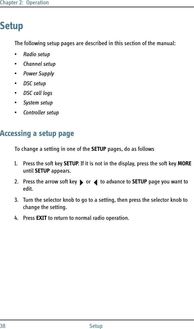
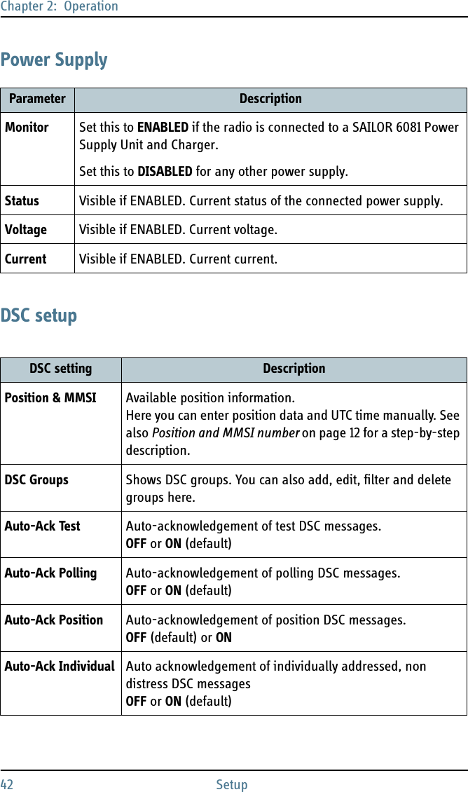
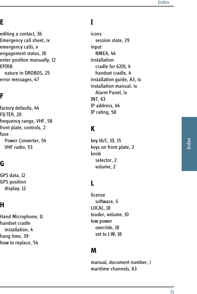
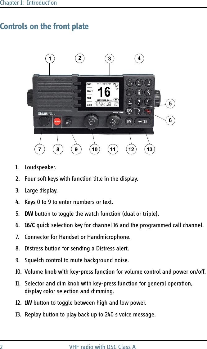
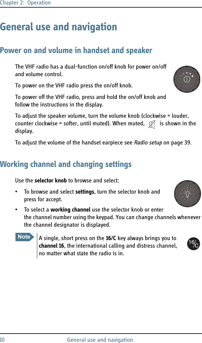
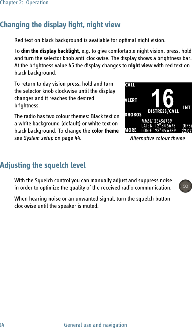
![Chapter 2: Operation16 VHF radio communication5. Suggest a working channel other than 16 by saying: “Channel [suggested channel number]”.6. Say: “Over.” and release the PTT button to allow the caller to confirm the suggested new channel.7. Switch to the new channel using the keypad or by turning the selector knob to the agreed channel and begin your conversation. Press PTT only when you are talking.Making a radio telephone call on channel 16To make a radio telephone call, proceed as follows:1. Select channel 16.2. Lift the Handset or take another speaker device.3. Press the PTT button. The symbol TX shows that the VHF radio is transmitting on the working channel displayed.4. Say the name of the station you are calling three times.5. Say: “This is [your ship’s name]”.6. Say: “Over.” and release the PTT button to listen. The symbol RX shows that the radio is receiving on the working channel displayed7. When answered, agree upon a working channel other than 16.8. Switch to the new channel by entering the channel number to the agreed channel and begin your conversation.VHF channelsYou can change channels whenever the channel designator is displayed. Enter the channel using the keypad or turn the selector knob to browse through all channels that are available in the selected channel table. Only valid channel numbers are accepted. When browsing channels they appear in the display in the following order:CALLALERTDROBOSMOREMMSI:123456789INTLAT: N 12°34.5678LON:E 123°45.6789 (GPS)22:07DISTRESS/CALL16](https://usermanual.wiki/Thrane-and-Thrane-A-S/6222/User-Guide-1487844-Page-28.png)
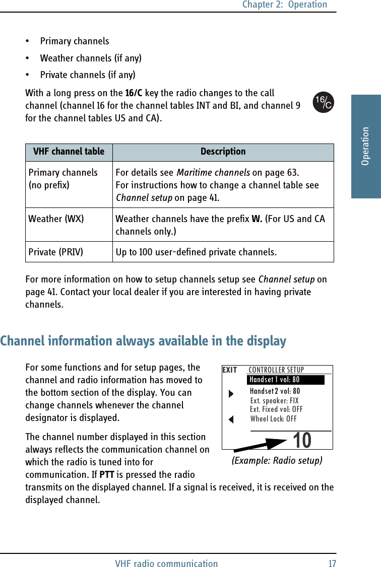
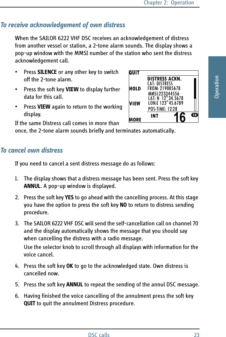
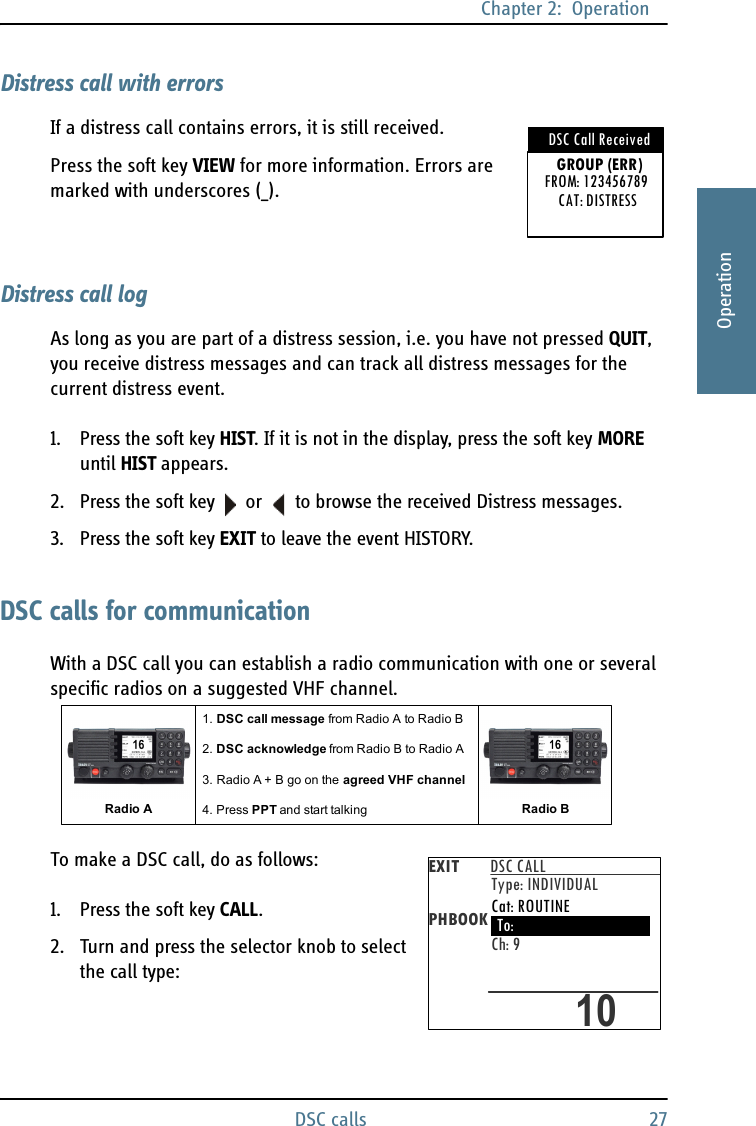
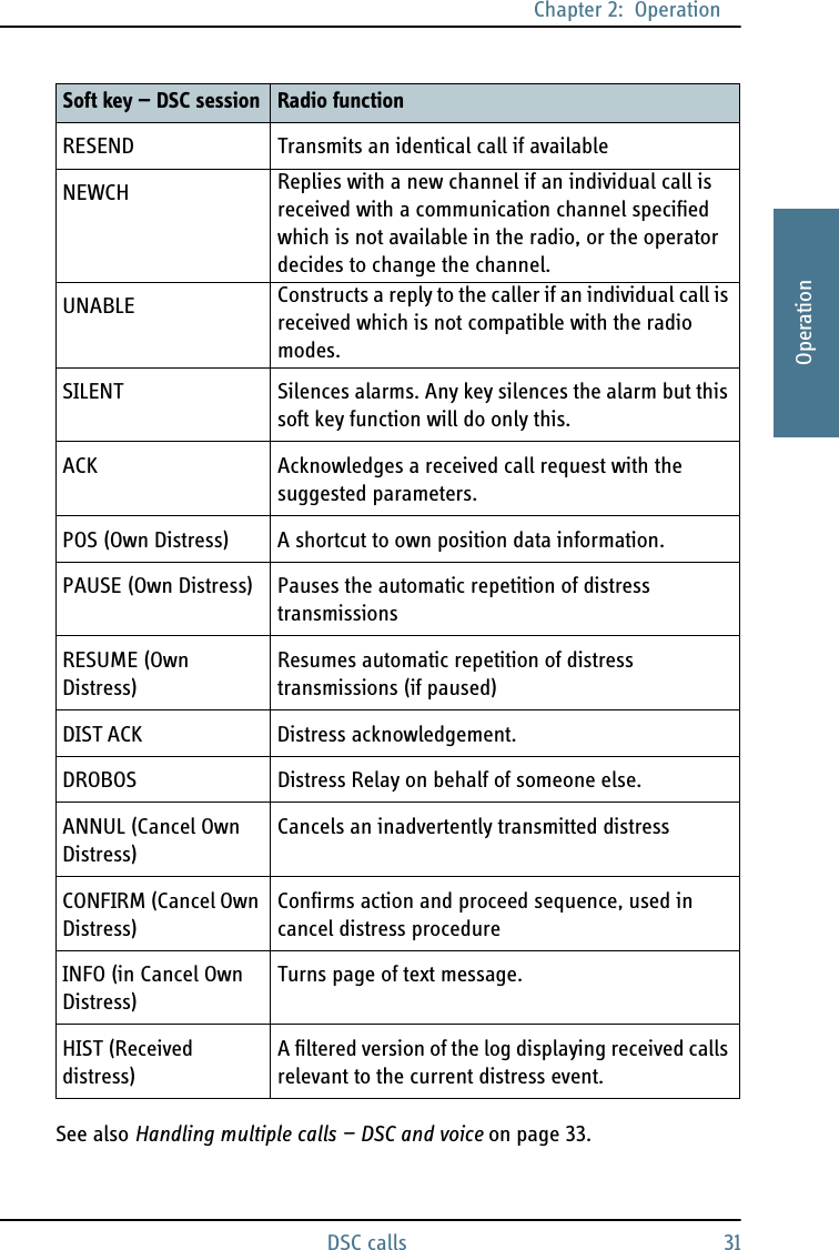
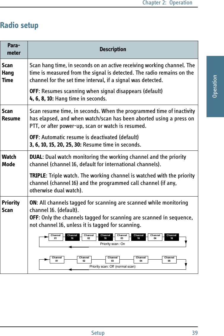
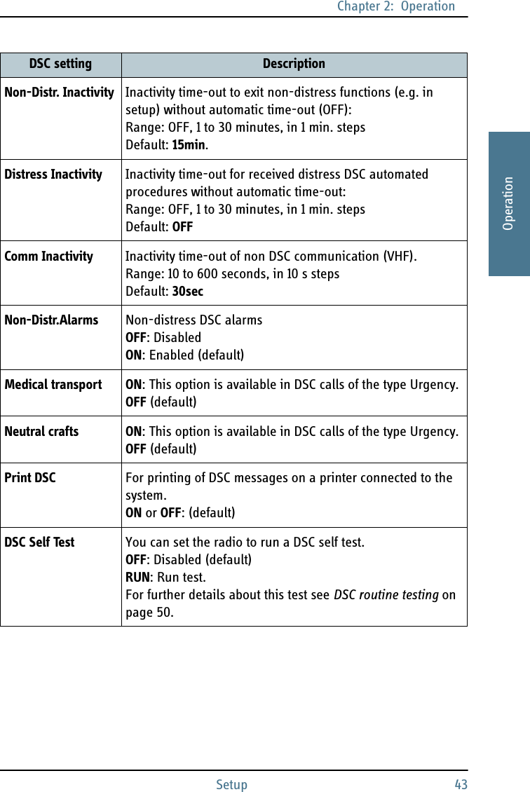
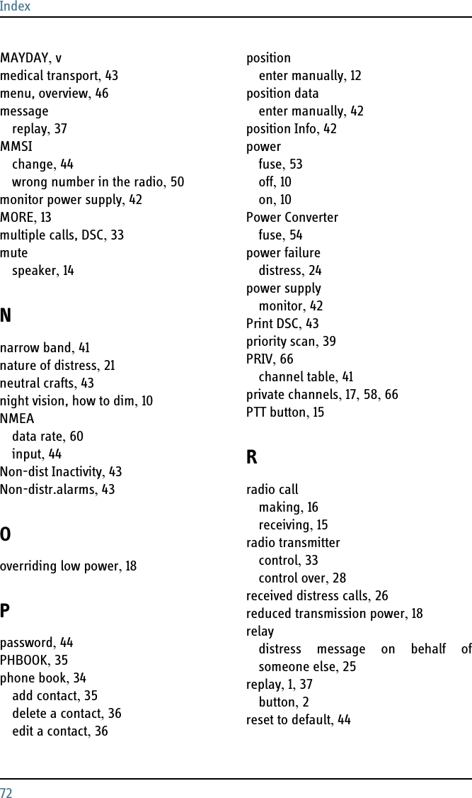
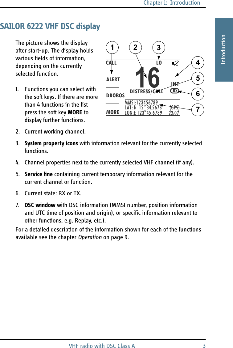
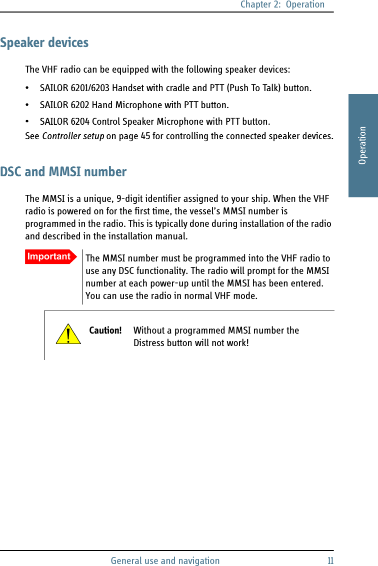
![Chapter 2: OperationWatch 192222OperationWatchThe SAILOR 6222 VHF DSC radio has a watch function with dual or triple watch. In dual watch, the working channel and channel 16 are watched. In triple watch the working channel, channel 16 and the programmed call channel are watched. You can select the working channel in any watch mode by turning the selector knob. If there is a signal in one of the watched channels, the display shows the channel in which the signal is received. For instructions how to setup TRIPLE WATCH see Radio setup on page 39.To start the watch function press the key DW. The radio enters the watch mode and the text WATCH with the channel numbers watched is shown below the current channel number. To stop the watch function press the key DW again or PTT on the speaking device.ScanThe radio has a scanning function for tagged voice channels. Any available voice channel, including weather and private channels, can be tagged and added to the scanning sequence. As default the radio scans with priority scanning of channel 16. If a signal is received while in any scanning mode, only channel 16 continues to be watched.16916924Dual watch Triple watchWorking channel + channel 16Working channel + channel 16+ call channelVIEWQUITCALLMOREMMSI:123456789INTWATCH [16]10LAT: N 12°34.5678LON:E 123°45.6789 (GPS)22:07](https://usermanual.wiki/Thrane-and-Thrane-A-S/6222/User-Guide-1487844-Page-31.png)
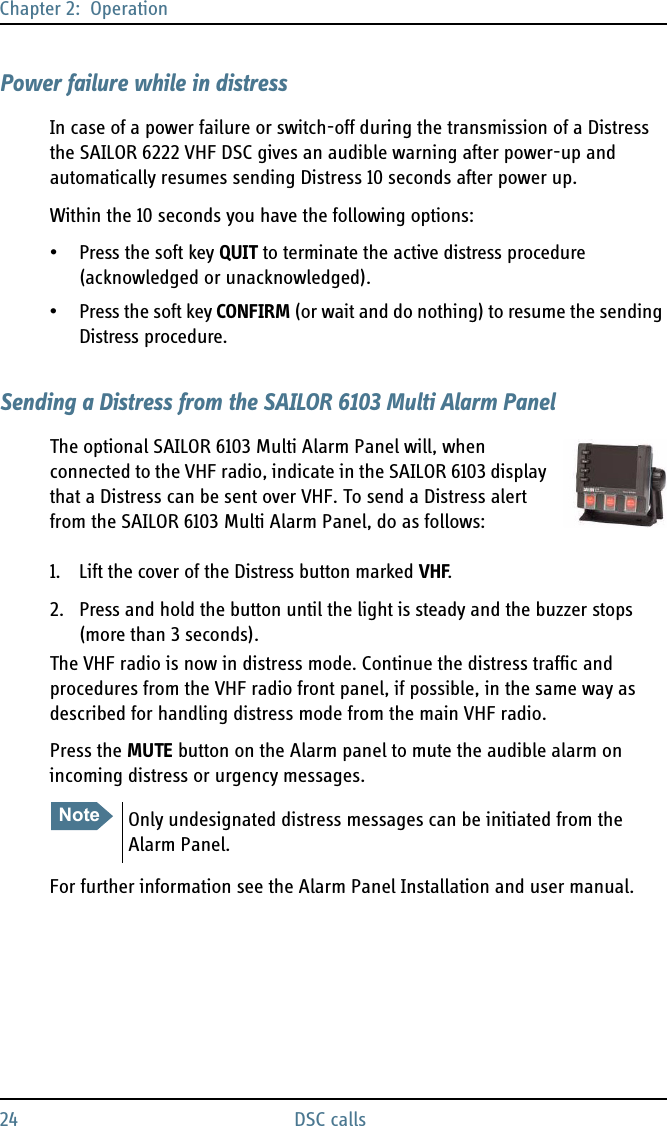
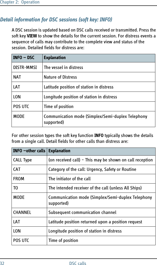
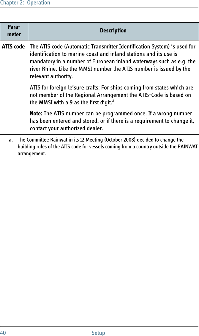
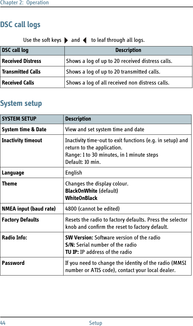
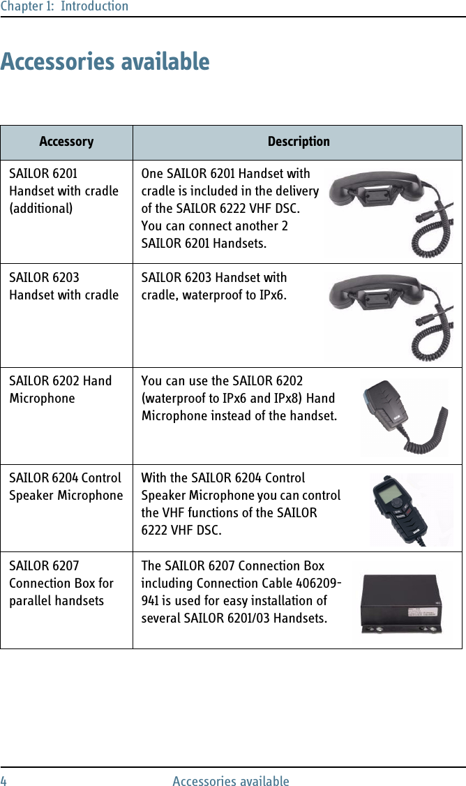
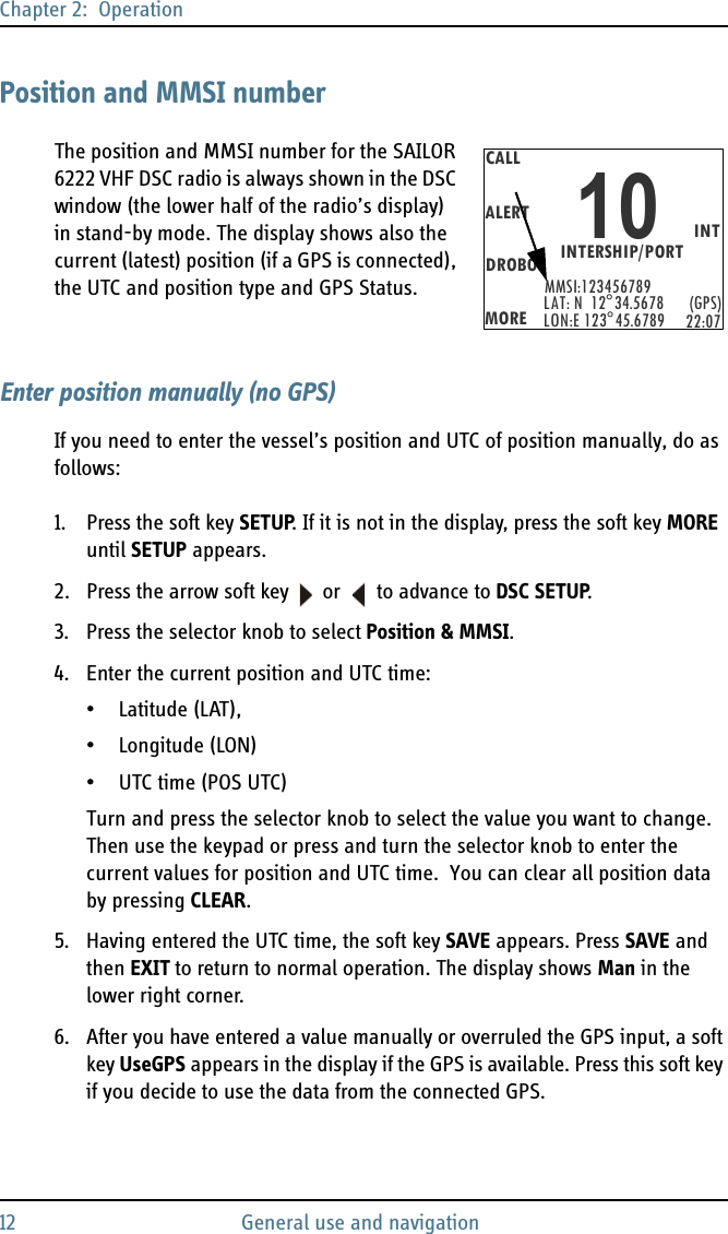
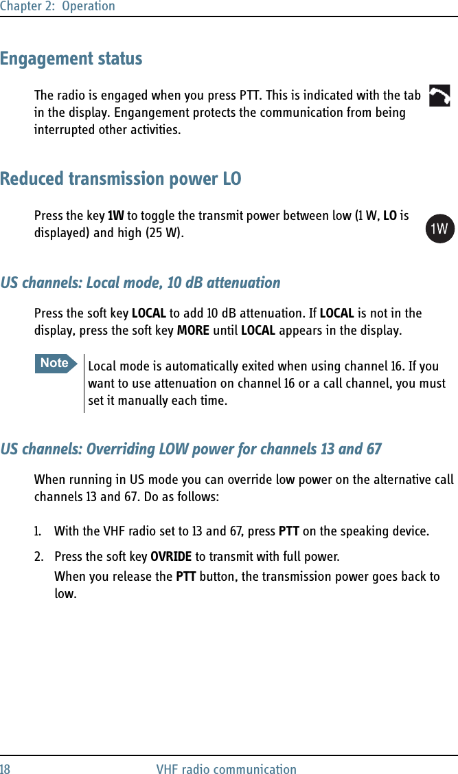
![Chapter 2: Operation20 DSC callsIf there is a signal in one of the scanned channels, the display shows the channel in which the signal is received. If PTT is pressed while scanning, the scanning stops, the radio is tuned into the displayed channel and transmission starts immediately on the displayed working channel.To start scanning press the soft key SCAN. The SCAN menu is shown. Press START to start scanning. To leave the SCAN menu, but not the scanning procedure, press EXIT.To stop scanning press STOP, QUIT if not in the SCAN menu, or press PTT on the speaking device.To tag a channel for scanning turn the selector knob until the wanted channel is in the display. Then press the soft key TAG. The display shows the channel number and the word TAG at the right side of the display.To remove a channel from the scanning sequence turn the selector knob until the tagged channel is displayed. Then press the soft key TAG to remove the tag.To see all tagged channels press the soft key FILTER and turn the selector knob. Press the soft key EXIT to leave the FILTER function. For details how to set up the scanning function see Radio setup on page 39.DSC callsIn this section of the manual you find information on:•Sending, acknowledging and cancelling own distress•DROBOSE — Distress Relay on behalf of someone else•Receiving distress calls•DSC calls for communicationNoteThe displayed working channel is temporarily included in the scanning list (although no TAG icon is shown).10EXITSTARTTAGMOREMMSI: 123456789INTINTERSHIP/PORTLAT: N 12°34.5678LON: E 123°45. 6789 (GPS)22:07EXITSC STOPTAGMOREMMSI: 123456789INTSCANNING[16]10LAT: N 12°34.5678LON: E 123°45.6789 (GPS)22:07](https://usermanual.wiki/Thrane-and-Thrane-A-S/6222/User-Guide-1487844-Page-32.png)