Thrane and Thrane A S 6222 SAILOR 6222 VHF DSC class A for GMDSS User Manual AdvancedVHF
Thrane & Thrane A/S SAILOR 6222 VHF DSC class A for GMDSS AdvancedVHF
user manual
SAILOR 6222 VHF DSC
User manual
Document number: 98-131184-C
Release date: June 20, 2011
Disclaimer
Any responsibility or liability for loss or damage in connection with the use of this
product and the accompanying documentation is disclaimed by Thrane & Thrane. The
information in this manual is provided for information purposes only, is subject to
change without notice and may contain errors or inaccuracies.
Manuals issued by Thrane & Thrane are periodically revised and updated. Anyone
relying on this information should acquire the most current version e.g. from
http://www.thrane.com or from the distributor.
Thrane & Thrane is not responsible for the content or accuracy of any translations or
reproductions, in whole or in part, of this manual from any other source.
Copyright
© 2011 Thrane & Thrane A/S. All rights reserved.
Trademark Acknowledgements
• Thrane & Thrane is a registered trademark of Thrane & Thrane A/S in the European
Union and the United States.
•SAILOR is a registered trademarks of Thrane & Thrane A/S.
• Other product and company names mentioned in this manual may be trademarks or
trade names of their respective owners.
GPL notification
The software included in this product contains copyrighted software that is licensed
under the GPL/LGPL. The verbatim licenses can be found online at:
http://www.gnu.org/licenses/old-licenses/gpl-2.0.html
http://www.gnu.org/licenses/old-licenses/lgpl-2.1.html
You may obtain the complete corresponding source code from us for a period of three
years after our last shipment of this product, which will be no earlier than December 31,
2015, by sending a money order or check for DKK 50 to:
SW Technology/GPL Compliance,
Thrane & Thrane A/S,
Lundtoftegaardsvej 93D
2800 Lyngby
DENMARK
Please write "source for product SAILOR 6222 VHF DSC" in the memo line of your
payment.
You may also find a copy of the source at http://www.thrane.com/foss.
This offer is valid to anyone in receipt of this information.
Warranties
Any attempt to install or execute software not supplied by Thrane & Thrane on this
device will result in the warranty being void. Any attempt to modify the software on this
device in a way not specified by Thrane & Thrane will result in the warranty being void.

iv
Safety warning 1
The following general safety precautions must be observed during all
phases of operation, service and repair of this equipment. Failure to comply
with these precautions or with specific warnings elsewhere in this manual
violates safety standards of design, manufacture and intended use of the
equipment. Thrane & Thrane assumes no liability for the customer's failure
to comply with these requirements.
Ground the equipment
To minimise shock hazard, the SAILOR 6222 VHF DSC unit must be connected
to an electrical ground and the cable instructions must be followed.
RF exposure hazards and instructions
Your Thrane & Thrane radio set generates electromagnetic RF (radio
frequency) energy when transmitting. To ensure that you and those around
you are not exposed to excessive amounts of energy and thus to avoid health
hazards from excessive exposure to RF energy, all persons must be at least
200 cm away from the antenna when the radio is transmitting.
Warranty limitation
IMPORTANT - The radio is a sealed waterproof unit (classified IPX8). To
create and maintain its waterproof integrity it was assembled in a controlled
environment using special equipment. The radio is not a user maintainable
unit, and under no circumstances should the unit be opened except by
authorized personnel. Unauthorized opening of the unit will invalidate the
warranty.
Installation and service
Installation and general service must be done by skilled service personnel.
Compass safe distance
Minimum safety distance: 0.85 m from the SAILOR 6222 VHF DSC.
v
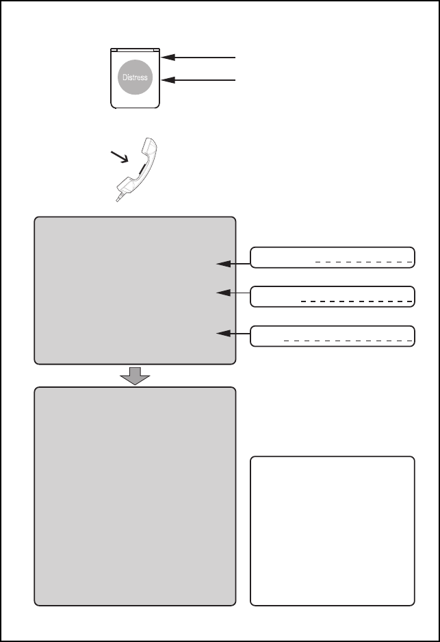
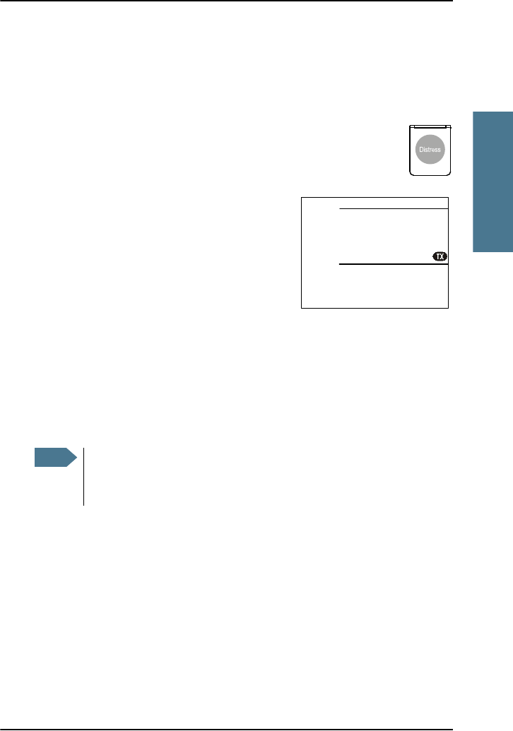
Emergency calls
MM
MM
MAA
AA
AYY
YY
YDD
DD
DAA
AA
AYY
YY
Y
NANA
NANA
NAMEME
MEME
ME of the VV
VV
VEE
EE
ESS
SS
SSS
SS
SELEL
ELEL
EL in distress
CC
CC
CALAL
ALAL
ALLL
LL
LSS
SS
SIGNIGN
IGNIGN
IGN or other IDENIDEN
IDENIDEN
IDENTT
TT
TIFICIFIC
IFICIFIC
IFICAA
AA
ATT
TT
TIONION
IONION
ION
MM
MM
MMM
MM
MS
S
SS
SII
II
I
(If the initial alert is sent by DSC)
PP
PP
POO
OO
OSS
SS
SITIT
ITIT
ITIONION
IONION
ION
given as ll
ll
latat
atat
atitit
itit
itudeude
udeude
ude and longitlongit
longitlongit
longitudeude
udeude
ude
or
If latitude and longitude are not known
or if time is insufficient,
in relation to a known geographical location
NANA
NANA
NA
TURETURE
TURETURE
TURE of distress
Kind of AA
AA
ASS
SS
SSS
SS
SII
II
ISS
SS
STT
TT
TANCANC
ANCANC
ANCEE
EE
E required
Any other useful INFINF
INFINF
INFOROR
OROR
ORMM
MM
MAA
AA
ATT
TT
TIONION
IONION
ION
MM
MM
MAA
AA
AYY
YY
YDD
DD
DAA
AA
AYY
YY
Y-M-M
-M-M
-MAA
AA
AYY
YY
YDD
DD
DAA
AA
AYY
YY
Y-M-M
-M-M
-MAA
AA
AYY
YY
YDD
DD
DAA
AA
AYY
YY
Y
This is
NANA
NANA
NAME-NAME-NA
ME-NAME-NA
ME-NAME-NAME-NA
ME-NAME-NA
ME-NAMEME
MEME
ME
CC
CC
CALAL
ALAL
ALLL
LL
LSS
SS
SIGNIGN
IGNIGN
IGN
or other IDENTIFICATION
MM
MM
MMM
MM
MSS
SS
SII
II
I
(If the initial alert is sent by DSC)
Use the HANDHAND
HANDHAND
HANDSS
SS
SETET
ETET
ET
for voice calling
LL
LL
Lifif
ifif
ift Ct C
t Ct C
t Covov
ovov
overer
erer
er
PP
PP
Prr
rr
ree
ee
ess
ss
ss RED Buttons RED Button
s RED Buttons RED Button
s RED Button
until beep sounds continuously
(more than 3 seconds)
SHIP‘s NAME:
CALLSIGN:
MMSI:
OWN OWN
OWN OWN
OWN IDID
IDID
ID
99-132140
Press
VHF
MF
HF4
HF6
HF8
HF12
HF16
Channel 70
2187.5 kHz
4207.5 kHz
6312.0 kHz
8414.5 kHz
12577.0 kHz
16804.5 kHz
Channel 16
2182.0 kHz
4125.0 kHz
6215.0 kHz
8291.0 kHz
12290.0 kHz
16420.0 kHz
- - - - -
2174.5 kHz
4177.5 kHz
6268.0 kHz
8376.5 kHz
12520.0 kHz
16695.0 kHz
DD
DD
DSCSC
SCSC
SC RR
RR
Radiadi
adiadi
adiotot
otot
otelephonelephon
elephonelephon
elephonyy
yy
yNBDPNBDP
NBDPNBDP
NBDP
DIDI
DIDI
DISS
SS
STRETRE
TRETRE
TRESS
SS
SSS
SS
S and C and C
and C and C
and COMOM
OMOM
OMMM
MM
MUNICUNIC
UNICUNIC
UNICAA
AA
ATT
TT
TIONION
IONION
ION
FREQUENCIEFREQUENCIE
FREQUENCIEFREQUENCIE
FREQUENCIESS
SS
S
_ _ _ _ _ _ _ _ _ _ _ _ _ _ _ _ _ _ _ _ _ _ _ _ _ _ _ _ _ _ _ _ _ _ _ _
Remember to use the correct HF-procedures
Don‘t forget your EPIRB is the secondary means of
alerting
_ _ _ _ _ _ _ _ _ _ _ _ _ _ _ _ _ _ _ _ _ _ _ _ _ _ _ _ _ _ _ _ _ _ _ _

vi
Preface 2
Radio for occupational use
The SAILOR 6222 VHF DSC fulfils the requirements of the Marine
Equipment Directive 96/98/EC and the amending Directive
2002/75/EC and is intended for use in maritime environment.
SAILOR 6222 VHF DSC is designed for occupational use only and
must be operated by licensed personnel only.
SAILOR 6222 VHF DSC is not intended for use in an uncontrolled
environment by general public.
SAILOR 6222 VHF DSC is designed for installation by a skilled
service person.

vii
Training information 3
The SAILOR 6222 VHF DSC is designed for occupational use only
and is also classified as such. It must be operated by licensed
personnel only. It must only be used in the course of employment
by individuals aware of both the hazards as well as the way to
minimize those hazards
The radio is thus NOT intended for use in an uncontrolled
environment by general public. The SAILOR 6222 VHF DSC has
been tested and complies with the FCC RF exposure limits for
Occupational Use Only. The radio also complies with the following
guidelines and standards regarding RF energy and
electromagnetic energy levels including the recommended levels
for human exposure:
• FCC OET Bulletin 65 Supplement C, evaluating compliance with
FCC guidelines for human exposure to radio frequency
electromagnetic fields.
• American National Standards Institute (C95.1) IEEE standard for
safety levels with respect to human exposure to radio frequency
electromagnetic fields, 3 kHz to 300 GHz
• American National Standards Institute (C95.3) IEEE
recommended practice for the measurement of potentially
hazardous electromagnetic fields - RF and microwaves.
Below the RF exposure hazards and instructions in safe operation
of the radio within the FCC RF exposure limits established for it are
described.
Warning
Your Thrane & Thrane radio set generates electromagnetic RF
(radio frequency) energy when it is transmitting. To ensure that
you and those around you are not exposed to excessive amounts of
that energy (beyond FCC allowable limits for occupational use) and
thus to avoid health hazards from excessive exposure to RF
energy, FCC OET bulletin 65 establishes an Maximum Permissible
Exposure (MPE) radius of 200 cm for the maximum power of your
radio (25W selected) with an half wave omni-directional antenna

viii
having a maximum gain of 4 dB. This means all persons must be at
least 200 cm away from the antenna when the radio is
transmitting.
Installation
1. An omni-directional antenna with a maximum power gain of
4 dB must be mounted at least 400 cm above the highest deck
where people may be staying during radio transmissions. The
distance is to be measured vertically from the lowest point of
the antenna. This provides the minimum separation distance
which is in compliance with RF exposure requirements and is
based on the MPE radius of 200 cm plus the 200 cm height of
an adult.
2. On vessels that cannot fulfil requirements in item 1, the antenna
must be mounted so that its lowest point is at least 3 ft. (0.9m)
vertically above the heads of people on deck and all persons
must be outside the 200 cm MPE radius during radio
transmission.
• Always mount the antenna at least 200 cm from possible
human access.
• Never touch the antenna when transmitting
• Use only authorized T&T accessories.
3. If the antenna has to be placed in public areas or near people
with no awareness of the radio transmission, the antenna must
be placed at a distance not less than 200 cm from possible
human access.
Failure to observe any of these warnings may cause you or other
people to exceed FCC RF exposure limits or create other dangerous
conditions.
ix
Manual overview
This manual has the following chapters and appendices:
• Introduction contains a description of the VHF radio.
•Operation explains how to make and receive voice and DSC
calls over VHF, including how to use and set-up scanning,
watch and replay.
•Service & maintenance contains support information including
lists of accessories and a troubleshooting guide.
• Appendix with Technical specifications and Maritime channels.
Related documents
Important
All installation information and instructions are not covered in this
manual. Please download the SAILOR 6222 VHF DSC Installation
manual (98-132904) at http://extranet.thrane.com/.
In the installation manual you can read how to mount the VHF radio
and how to connect accessories and external equipment, including
detailed system configuration examples with cable specifications.
Title and description Document number
SAILOR 6222 VHF DSC, Installation guide 98-132281
SAILOR 6222 VHF DSC Installation manual
(download only)
98-132904
SAILOR 6101 and 6103 Alarm Panel,
Installation and user manual
98-130981
Emergency call sheet 98-132369

x

xi
Table of Contents
Chapter 1 Introduction
VHF radio with DSC Class A ................................................ 1
Accessories available .........................................................4
Chapter 2 Operation
Overview ............................................................................9
General use and navigation ............................................. 10
VHF radio communication .................................................15
Watch ................................................................................19
Scan ..................................................................................19
DSC calls ..........................................................................20
Handling multiple calls — DSC and voice ..........................33
Phone book ......................................................................34
Replay function ................................................................ 37
Setup ...............................................................................38
Chapter 3 Service & maintenance
Contact for support ...........................................................47
Maintenance ....................................................................47
Troubleshooting guide .....................................................49
Warranty and returning units for repair ...........................55
App. A Technical specifications
Transceiver unit SAILOR 6222 VHF DSC .............................57
General DSC specifications ...............................................60

Table of Contents
xii
NMEA data rates and formats .......................................... 60
SAILOR 6090 Power Converter 24—12 V ............................. 61
App. B Maritime channels
International channels (INT) .............................................63
US channels .....................................................................64
CA channels .....................................................................65
BI channels ......................................................................66
Glossary .........................................................................................67
Index ........................................................................................ 69
1
Chapter 1
1111
Introduction
Introduction 1
VHF radio with DSC Class A
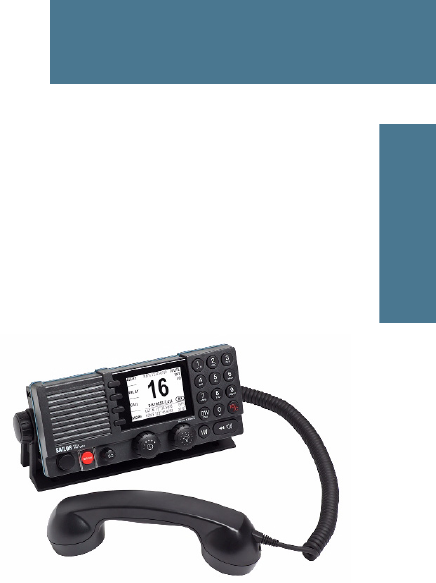
SAILOR 6222 VHF DSC, your
new VHF radio with full DSC
functionality, is approved to
MED, FCC and Industry
Canada and is waterproof to
the IPx8 and IPx6 standard.
As part of the required safety
equipment, use the SAILOR
6222 VHF DSC in an
emergency situation. However
the best way to guarantee
functionality in an emergency situation, is to use the radio in daily
communication on board.
The VHF radio is a simplex/semi duplex VHF radio. It is designed with an easy-
to-use menu-driven setup. You use the soft-keys and the keypad to enter the
desired functions, you browse and select a setting using the right selection
knob. The large display can be customized for optimum readability and
visibility both day and night with several color themes.
The VHF radio can replay the last 240 s of received voice messages. This is a
useful feature to minimize misunderstandings and to record messages when
the radio is unattended.
With SAILOR connection boxes the VHF radio connects easily to external
equipment like additional handsets, water proof hand microphones, control
speaker microphone, alarm panel or external speaker. The Ethernet interface
enables the VHF radio to be connected to ThraneLINK for remote control and
service updates.
For a list of accessories available for the VHF radio see Accessories available
on page 4 and check with your nearest distributor.
Chapter 1: Introduction
2 VHF radio with DSC Class A
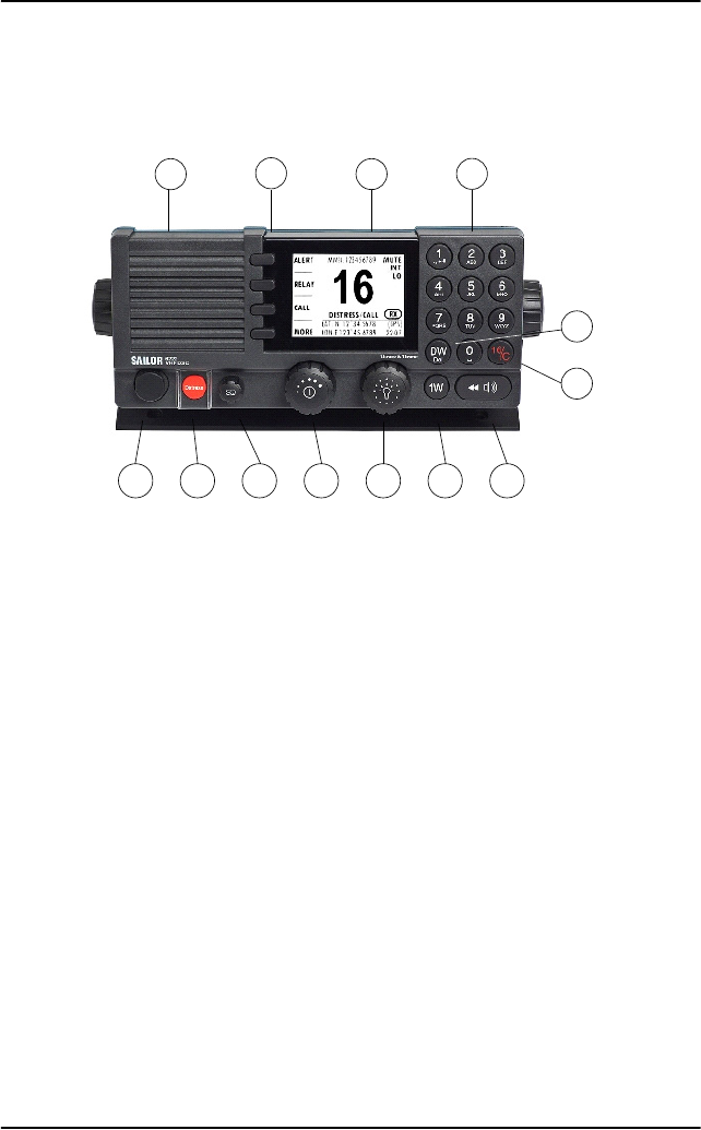
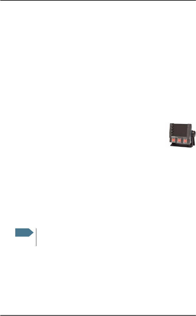
Controls on the front plate
1. Loudspeaker.
2. Four soft keys with function title in the display.
3. Large display.
4. Keys 0 to 9 to enter numbers or text.
5. DW button to toggle the watch function (dual or triple).
6. 16/C quick selection key for channel 16 and the programmed call channel.
7. Connector for Handset or Handmicrophone.
8. Distress button for sending a Distress alert.
9. Squelch control to mute background noise.
10. Volume knob with key-press function for volume control and power on/off.
11. Selector and dim knob with key-press function for general operation,
display color selection and dimming.
12. 1W button to toggle between high and low power.
13. Replay button to play back up to 240 s voice message.
5
6
7 8 9 10 11 12 13
1234
Chapter 1: Introduction
VHF radio with DSC Class A 3
1111
Introduction
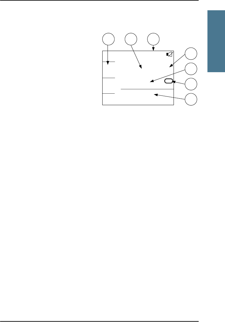
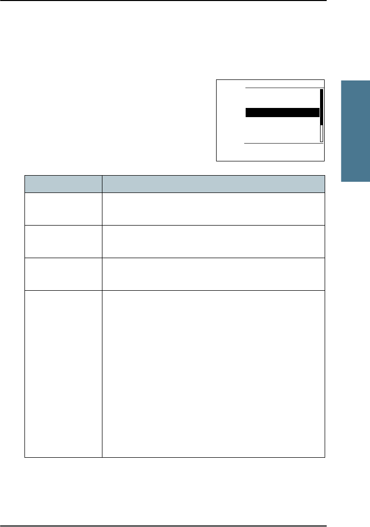
SAILOR 6222 VHF DSC display
The picture shows the display
after start-up. The display holds
various fields of information,
depending on the currently
selected function.
1. Functions you can select with
the soft keys. If there are more
than 4 functions in the list
press the soft key MORE to
display further functions.
2. Current working channel.
3. System property icons with information relevant for the currently selected
functions.
4. Channel properties next to the currently selected VHF channel (if any).
5. Service line containing current temporary information relevant for the
current channel or function.
6. Current state: RX or TX.
7. DSC window with DSC information (MMSI number, position information
and UTC time of position and origin), or specific information relevant to
other functions, e.g. Replay, etc.).
For a detailed description of the information shown for each of the functions
available see the chapter Operation on page 9.
5
6
4
CALL
ALERT
DROBOS
MORE
MMSI:123456789
INT
LO
DISTRESS/CALL
16
LAT: N 12°34.5678
LON:E 123°45.6789 (GPS)
22:07
RX
3
21
7
Chapter 1: Introduction
4 Accessories available
Accessories available
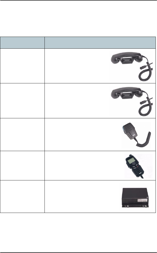
Accessory Description
SAILOR 6201
Handset with cradle
(additional)
One SAILOR 6201 Handset with
cradle is included in the delivery
of the SAILOR 6222 VHF DSC.
You can connect another 2
SAILOR 6201 Handsets.
SAILOR 6203
Handset with cradle
SAILOR 6203 Handset with
cradle, waterproof to IPx6.
SAILOR 6202 Hand
Microphone
You can use the SAILOR 6202
(waterproof to IPx6 and IPx8) Hand
Microphone instead of the handset.
SAILOR 6204 Control
Speaker Microphone
With the SAILOR 6204 Control
Speaker Microphone you can control
the VHF functions of the SAILOR
6222 VHF DSC.
SAILOR 6207
Connection Box for
parallel handsets
The SAILOR 6207 Connection Box
including Connection Cable 406209-
941 is used for easy installation of
several SAILOR 6201/03 Handsets.
Chapter 1: Introduction
Accessories available 5
1111
Introduction
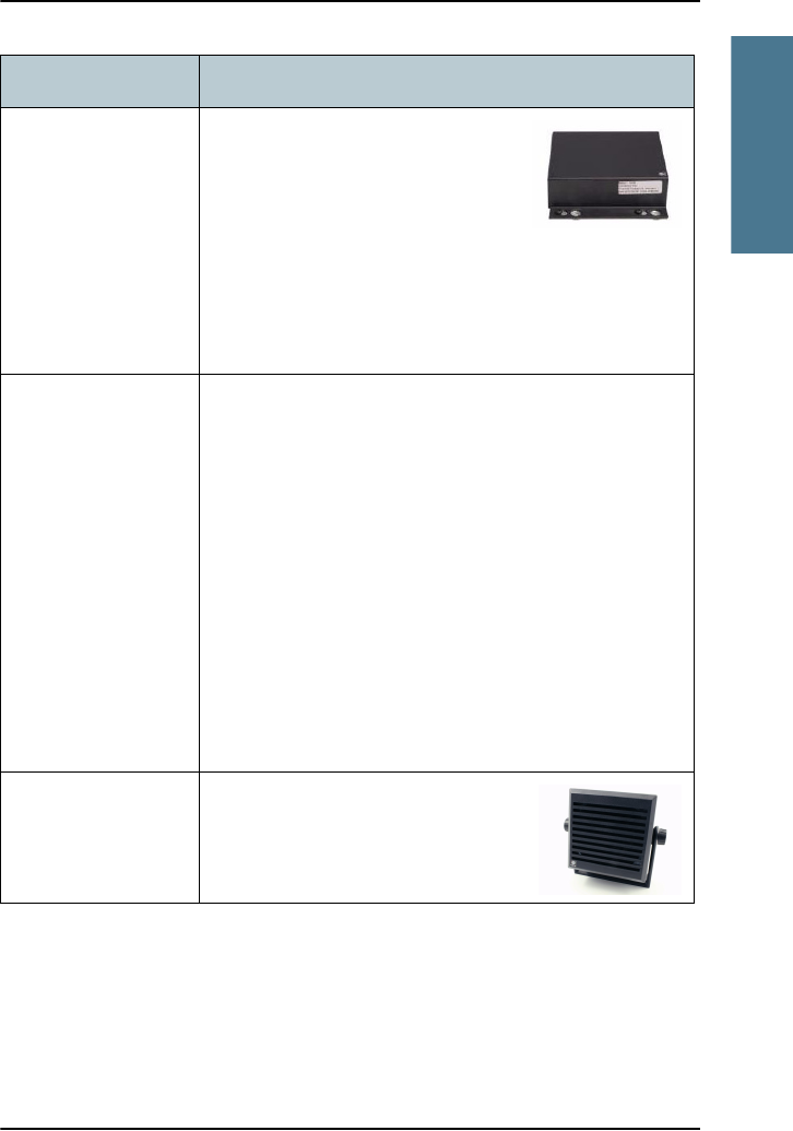
SAILOR 6208 Control
Unit Connection Box
The SAILOR 6208 Connection Box
including Connection Cable 406208-
941 is used for easy installation of
external equipment and accessories:
• Max. 4 SAILOR 6204 Control Speaker Microphones
•VDR
•SAILOR6270 External loudspeaker
• Alarm panels and GPS input
Connection cables
5m connection cable for bulkhead mount: Use this cable
in installations where the SAILOR 6201 or 6203 Handset
is not connected directly to the SAILOR 6222 VHF DSC,
but located in a different position (part number: 406204-
940).
5m Connection cable, 1x10 pole: Use this cable in
installations when connecting external equipment to the
SAILOR 6222 VHF DSC. This cable is included in the
SAILOR 6207 Connection Box for parallel handsets (part
number: 406207-941).
5 m Connection cable for SAILOR 6204 Control Speaker
Microphone, 1x12 pole (part number: 406204-940).
SAILOR 6270
External
loudspeaker
If you need an additional external
loudspeaker you can connect a
SAILOR 6270 Loudspeaker. It provides
6 W output power.
Accessory Description
Chapter 1: Introduction
6 Accessories available
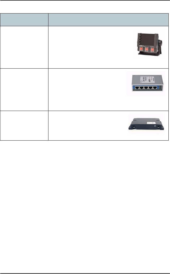
SAILOR 6103 Multi
Alarm Panel
With the SAILOR 6103 Multi Alarm
Panel you can activate GMDSS Distress
Alarms. The Multi Alarm Panel can be
connected to the SAILOR 6222 VHF DSC
via the Ethernet interface (LAN
connector, ThraneLINK).
SAILOR 6197
Ethernet Switch
The SAILOR 6197 Ethernet Switch
is used in installations with
SAILOR 6103 GMDSS Alarm Panels
and in installations with
ThraneLINK. The Ethernet switch
has 5 ports.
SAILOR 6090 Power
Converter 24 V to
12 V DC
The SAILOR 6090 Power Converter
is used to provide 12 V DC for the
SAILOR 6222 VHF DSC from a 24 V
DC power source.
Accessory Description
Chapter 1: Introduction
Accessories available 7
1111
Introduction
System configuration — example
The SAILOR 6222 VHF DSC can be customized to suit your installation. The
following illustration is one example of a system. For further configuration
examples see the installation manual, Appendix B, System configurations.
Speaker Microphone
Control
(NMEA)
GPS, AIS, etc.
Speaker (8 ohm)
External
SAILOR 6204
SAILOR 6201/03
Handset Option
SAILOR 6201/03
Remote Control + Service
ETHERNET port
99-128194-J
406209-940
Cable
406209-940
Cable
(without DSC)
LAN
12V DC
110/220V AC
Handset Option
Handset
SAILOR 6201/03
Handmicrophone
SAILOR 6202
Alarm
DSC Call
AUX
GPS
ACC. Port
VDR
Max 4 SAILOR 6204
Power Converter
SAILOR 6090
SAILOR 6208
Connection Box
Power
Power Supply
SAILOR N163S
SAILOR 6208
Connection Box
SAILOR 6207
Connection Box
for Parallel Handsets
406208-941
Cable
AUX. Port
CTRL. Port
406209-941
Cable
24V DC
VHF DSC
6222
Multi Alarm Panel
SAILOR 6103
12V Battery
24V DC
Aerial
RX/TX
Aerial
RX/DSC

Chapter 1: Introduction
8 Accessories available

9
Chapter 2
2222
Operation
Operation 2
Overview
In this chapter you find detailed instructions and guidelines for:
•General use and navigation
•VHF radio communication
•Watch
•Scan
•DSC calls
•Handling multiple calls — DSC and voice
•Phone book
•Replay function
•Setup
Note
Before using the VHF radio make sure that the VHF and DSC antennas,
power cable and other external equipment are connected properly. For
installation instructions see the SAILOR 6222 VHF DSC Installation manual
(download only).
Chapter 2: Operation
10 General use and navigation
General use and navigation
Power on and volume in handset and speaker
The VHF radio has a dual-function on/off knob for power on/off
and volume control.
To power on the VHF radio press the on/off knob.
To power off the VHF radio, press and hold the on/off knob and
follow the instructions in the display.
To adjust the speaker volume, turn the volume knob (clockwise = louder,
counter clockwise = softer, until muted). When muted, is shown in the
display.
To adjust the volume of the handset earpiece see Radio setup on page 39.
Working channel and changing settings
Use the selector knob to browse and select:
• To browse and select settings, turn the selector knob and
press for accept.
• To select a working channel use the selector knob or enter
the channel number using the keypad. You can change channels whenever
the channel designator is displayed.
Note
A single, short press on the 16/C key always brings you to
channel 16, the international calling and distress channel,
no matter what state the radio is in.
Chapter 2: Operation
General use and navigation 11
2222
Operation
Speaker devices
The VHF radio can be equipped with the following speaker devices:
• SAILOR 6201/6203 Handset with cradle and PTT (Push To Talk) button.
• SAILOR 6202 Hand Microphone with PTT button.
• SAILOR 6204 Control Speaker Microphone with PTT button.
See Controller setup on page 45 for controlling the connected speaker devices.
DSC and MMSI number
The MMSI is a unique, 9-digit identifier assigned to your ship. When the VHF
radio is powered on for the first time, the vessel’s MMSI number is
programmed in the radio. This is typically done during installation of the radio
and described in the installation manual.
Important
The MMSI number must be programmed into the VHF radio to
use any DSC functionality. The radio will prompt for the MMSI
number at each power-up until the MMSI has been entered.
You can use the radio in normal VHF mode.
Caution! Without a programmed MMSI number the
Distress button will not work!

Chapter 2: Operation
12 General use and navigation
Position and MMSI number
The position and MMSI number for the SAILOR
6222 VHF DSC radio is always shown in the DSC
window (the lower half of the radio’s display)
in stand-by mode. The display shows also the
current (latest) position (if a GPS is connected),
the UTC and position type and GPS Status.
Enter position manually (no GPS)
If you need to enter the vessel’s position and UTC of position manually, do as
follows:
1. Press the soft key SETUP. If it is not in the display, press the soft key MORE
until SETUP appears.
2. Press the arrow soft key or to advance to DSC SETUP.
3. Press the selector knob to select Position & MMSI.
4. Enter the current position and UTC time:
• Latitude (LAT),
• Longitude (LON)
• UTC time (POS UTC)
Turn and press the selector knob to select the value you want to change.
Then use the keypad or press and turn the selector knob to enter the
current values for position and UTC time. You can clear all position data
by pressing CLEAR.
5. Having entered the UTC time, the soft key SAVE appears. Press SAVE and
then EXIT to return to normal operation. The display shows Man in the
lower right corner.
6. After you have entered a value manually or overruled the GPS input, a soft
key UseGPS appears in the display if the GPS is available. Press this soft key
if you decide to use the data from the connected GPS.
CALL
ALERT
DROBOS
MORE
MMSI:123456789
INT
INTERSHIP/PORT
10
LAT: N 12°34.5678
LON:E 123°45.6789 (GPS)
22:07
Chapter 2: Operation
General use and navigation 13
2222
Operation
If the GPS was present and then disappears a warning appears in the display
after 10 minutes, then you can enter the position and UTC time manually as
described above.
Soft-key functions
A number of functions of the SAILOR
6222 VHF DSC are accessed and set
using the four soft keys to the left of the
display. The current function of a soft
key is shown in the display next to the
soft key.
The following soft-key functions are
available from top-level standby:
Use the soft key MORE to display further soft key functions.
Soft key Function
CALL To make DSC non-distress calls
ALERT To make a distress call with assigned category
DROBOS Make a distress relay call on behalf of someone else
SCAN Scanning menu with start, stop and tag function
PHBOOK Phone book
LOCAL Local mode, 10 dB attenuation
SETUP Setup pages for Radio setup, Channel setup, Power Supply,
DSC setup, DSC call logs, System setup and Controller setup.
CALL
ALERT
DROBOS
MORE
MMSI:123456789
INT
DISTRESS/CALL
16
LAT: N 12°34.5678
LON:E 123°45.6789 (GPS)
22:07

Chapter 2: Operation
14 General use and navigation
Changing the display light, night view
Red text on black background is available for optimal night vision.
To dim the display backlight, e.g. to give comfortable night vision, press, hold
and turn the selector knob anti-clockwise. The display shows a brightness bar.
At the brightness value 45 the display changes to night view with red text on
black background.
To return to day vision press, hold and turn
the selector knob clockwise until the display
changes and it reaches the desired
brightness.
The radio has two colour themes: Black text on
a white background (default) or white text on
black background. To change the color theme
see System setup on page 44.
Adjusting the squelch level
With the Squelch control you can manually adjust and suppress noise
in order to optimize the quality of the received radio communication.
When hearing noise or an unwanted signal, turn the squelch button
clockwise until the speaker is muted.
CALL
ALERT
DROBOS
MORE
MMSI:123456789
INT
DISTRESS/CALL
16
LAT: N 12°34.5678
LON:E 123°45.6789 (GPS)
22:07
Alternative colour theme
Chapter 2: Operation
VHF radio communication 15
2222
Operation
VHF radio communication
Basic VHF operation
You can make VHF calls using the Handset or another speaker device.
Quick guide to radio telephone calls
1. Press the PTT button on the speaker device. When the TX indicator
lights up in the display, the transmission is active.
2. To enable reception of a radio signal release the PTT button.
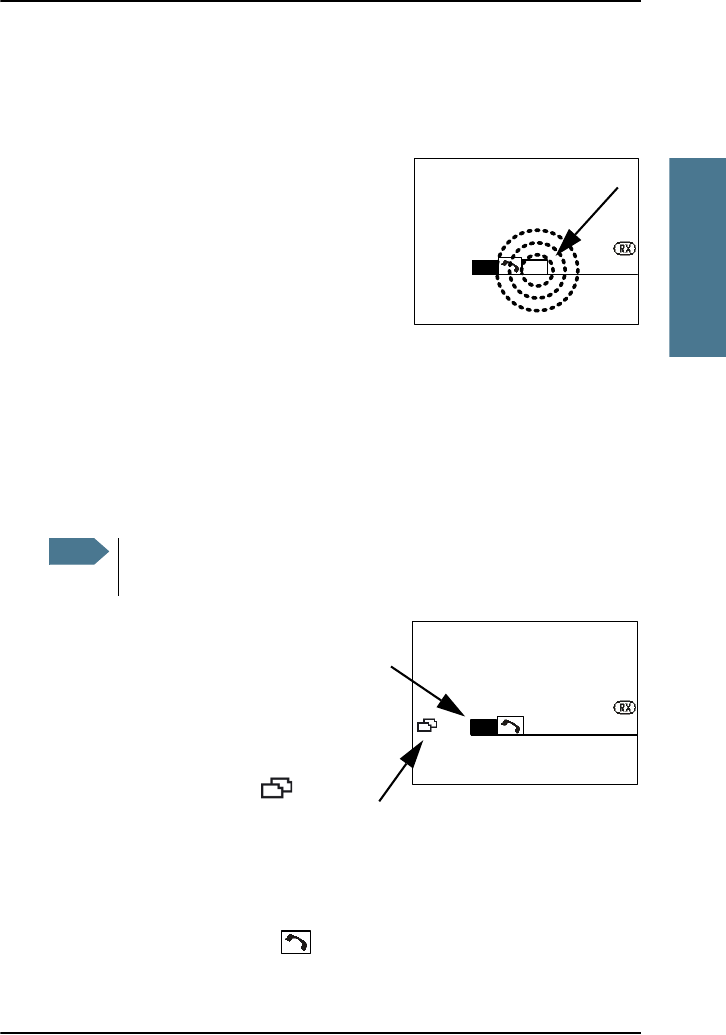
Receiving a radio telephone call on channel 16
When you hear your call name in the
loudspeaker, proceed as follows:
1. The symbol RX shows that the radio is
receiving on the channel displayed.
2. Lift the Handset or take another speaker
device.
3. Press the PTT button. The symbol TX shows that the radio is transmitting on
the channel displayed.
4. Repeat the name of the station calling you and say: “This is [your ship’s
name]”.
Note
A single, short press on the 16/C key always brings you to
channel 16, the international calling and distress channel,
no matter what state the radio is in.
Note
Press PTT only when you are talking. Always say “Over.” just before
releasing the PTT button.
One transmission is limited to 5 minutes duration.
TX
RX
CALL
ALERT
DROBOS
MORE
MMSI:123456789
INT
DISTRESS/CALL
16
LAT: N 12°34.5678
LON:E 123°45.6789 (GPS)
22:07

Chapter 2: Operation
16 VHF radio communication
5. Suggest a working channel other than 16 by saying: “Channel [suggested
channel number]”.
6. Say: “Over.” and release the PTT button to allow the caller to confirm the
suggested new channel.
7. Switch to the new channel using the keypad or by turning the selector knob
to the agreed channel and begin your conversation. Press PTT only when
you are talking.
Making a radio telephone call on channel 16
To make a radio telephone call, proceed as
follows:
1. Select channel 16.
2. Lift the Handset or take another speaker
device.
3. Press the PTT button. The symbol TX shows
that the VHF radio is transmitting on the working channel displayed.
4. Say the name of the station you are calling three times.
5. Say: “This is [your ship’s name]”.
6. Say: “Over.” and release the PTT button to listen. The symbol RX shows
that the radio is receiving on the working channel displayed
7. When answered, agree upon a working channel other than 16.
8. Switch to the new channel by entering the channel number to the agreed
channel and begin your conversation.
VHF channels
You can change channels whenever the channel designator is displayed. Enter
the channel using the keypad or turn the selector knob to browse through all
channels that are available in the selected channel table. Only valid channel
numbers are accepted. When browsing channels they appear in the display in
the following order:
CALL
ALERT
DROBOS
MORE
MMSI:123456789
INT
LAT: N 12°34.5678
LON:E 123°45.6789 (GPS)
22:07
DISTRESS/CALL
16
Chapter 2: Operation
VHF radio communication 17
2222
Operation
• Primary channels
• Weather channels (if any)
• Private channels (if any)
With a long press on the 16/C key the radio changes to the call
channel (channel 16 for the channel tables INT and BI, and channel 9
for the channel tables US and CA).
For more information on how to setup channels setup see Channel setup on
page 41. Contact your local dealer if you are interested in having private
channels.
Channel information always available in the display
For some functions and for setup pages, the
channel and radio information has moved to
the bottom section of the display. You can
change channels whenever the channel
designator is displayed.
The channel number displayed in this section
always reflects the communication channel on
which the radio is tuned into for
communication. If PTT is pressed the radio
transmits on the displayed channel. If a signal is received, it is received on the
displayed channel.
VHF channel table Description
Primary channels
(no prefix)
For details see Maritime channels on page 63.
For instructions how to change a channel table see
Channel setup on page 41.
Weather (WX) Weather channels have the prefix W. (For US and CA
channels only.)
Private (PRIV) Up to 100 user-defined private channels.
EXIT CONTROLLER SETUP
10
Handset 1 vol: 80
Handset 2 vol: 80
Ext. speaker: FIX
Ext. Fixed vol: OFF
Wheel Lock: OFF
(Example: Radio setup)

Chapter 2: Operation
18 VHF radio communication
Engagement status
The radio is engaged when you press PTT. This is indicated with the tab
in the display. Engangement protects the communication from being
interrupted other activities.
Reduced transmission power LO
Press the key 1W to toggle the transmit power between low (1 W, LO is
displayed) and high (25 W).
US channels: Local mode, 10 dB attenuation
Press the soft key LOCAL to add 10 dB attenuation. If LOCAL is not in the
display, press the soft key MORE until LOCAL appears in the display.
US channels: Overriding LOW power for channels 13 and 67
When running in US mode you can override low power on the alternative call
channels 13 and 67. Do as follows:
1. With the VHF radio set to 13 and 67, press PTT on the speaking device.
2. Press the soft key OVRIDE to transmit with full power.
When you release the PTT button, the transmission power goes back to
low.
Note
Local mode is automatically exited when using channel 16. If you
want to use attenuation on channel 16 or a call channel, you must
set it manually each time.
Chapter 2: Operation
Watch 19
2222
Operation
Watch
The SAILOR 6222 VHF DSC radio
has a watch function with dual
or triple watch. In dual watch,
the working channel and
channel 16 are watched. In triple
watch the working channel,
channel 16 and the programmed
call channel are watched. You
can select the working channel
in any watch mode by turning
the selector knob. If there is a
signal in one of the watched channels, the display shows the channel in which
the signal is received. For instructions how to setup TRIPLE WATCH see Radio
setup on page 39.
To start the watch function press the key DW. The radio enters the
watch mode and the text WATCH with the channel numbers watched
is shown below the current channel number.
To stop the watch function press the key DW
again or PTT on the speaking device.
Scan
The radio has a scanning function for tagged voice channels. Any available
voice channel, including weather and private channels, can be tagged and
added to the scanning sequence. As default the radio scans with priority
scanning of channel 16. If a signal is received while in any scanning mode,
only channel 16 continues to be watched.
16
9
16
924
Dual watch Triple watch
Working channel
+ channel 16
Working channel
+ channel 16
+ call channel
VIEW
QUIT
CALL
MORE
MMSI:123456789
INT
WATCH [16]
10
LAT: N 12°34.5678
LON:E 123°45.6789 (GPS)
22:07
Chapter 2: Operation
20 DSC calls
If there is a signal in one of the scanned channels, the display shows the
channel in which the signal is received. If PTT is pressed while scanning, the
scanning stops, the radio is tuned into the displayed channel and transmission
starts immediately on the displayed working channel.
To start scanning press the soft key SCAN. The
SCAN menu is shown. Press START to start
scanning. To leave the SCAN menu, but not the
scanning procedure, press EXIT.
To stop scanning press STOP, QUIT if not in the
SCAN menu, or press PTT on the speaking
device.
To tag a channel for scanning turn the selector
knob until the wanted channel is in the
display. Then press the soft key TAG. The
display shows the channel number and the
word TAG at the right side of the display.
To remove a channel from the scanning
sequence turn the selector knob until the
tagged channel is displayed. Then press the soft key TAG to remove the tag.
To see all tagged channels press the soft key FILTER and turn the selector
knob. Press the soft key EXIT to leave the FILTER function. For details how to
set up the scanning function see Radio setup on page 39.
DSC calls
In this section of the manual you find information on:
•Sending, acknowledging and cancelling own distress
•DROBOSE — Distress Relay on behalf of someone else
•Receiving distress calls
•DSC calls for communication
Note
The displayed working channel is temporarily included in the
scanning list (although no TAG icon is shown).
10
EXIT
START
TAG
MORE
MMSI: 123456789
INT
INTERSHIP/PORT
LAT: N 12°34.5678
LON: E 123°45. 6789 (GPS)
22:07
EXIT
SC STOP
TAG
MORE
MMSI: 123456789
INT
SCANNING[16]
10
LAT: N 12°34.5678
LON: E 123°45.6789 (GPS)
22:07
Chapter 2: Operation
DSC calls 21
2222
Operation
Sending, acknowledging and cancelling own distress
To send a distress message
1. Lift the cover of the red distress button and press and hold the
distress button for longer than 3 seconds. For short step-by-
step instructions how to proceed when sending a distress
message see Emergency calls on page v.
When the distress signal is sent, CH70 and
Tx appear in the display. A two-seconds
steady tone is heard.
2. The radio watches for a DSC
acknowledgement transmission on channel
70.
3. To pause the automatic resend procedure
press the soft key PAUSE.
4. To annul the distress message press the soft key ANNUL. See also To cancel
own distress on page 23.
5. When a distress acknowledgement is received, a pop-up window is
displayed. Start distress communication on channel 16 to inform about your
distress situation.
Having pressed the red distress button and sent the distress message, the
following information is displayed:
• STATION: shows the radio’s MMSI number.
• NAT: shows the nature of distress, see also ALERT: To send a distress
message with specified nature.
• LAT:, LON:, POS UTC: shows the distress position data as transmitted.
• MODE: shows the communication mode.
• Elapsed time after initiation of own distress.
Note
If no distress acknowledgement is received within a period of 3,5 to
4,5 minutes, the distress message will automatically be
retransmitted.
ANNUL
VIEW
PAUSE
INT
16
!!! OWN DISTRESS !!!
WAITING FOR REPLY
ELAPSED TIME: 1:33
REPEAT IN: 2.15
Chapter 2: Operation
22 DSC calls
• Time to next repeat of sending own distress.
If you sent a distress message, the VHF radio is automatically set to channel
16, the channel reserved for international distress, safety and calling.
ALERT: To send a distress message with specified nature
When sending distress messages you can include the distress nature in the
message. To include the distress nature in the distress message do as follows:
1. From top-level standby press the soft key
ALERT. If it is not in the display, press the
soft key MORE until ALERT appears.
If the current position information is not
correct, you can manually enter it by using
the soft key POS.
2. Press the selector knob, then turn it to
select a natures of distress:
FIRE, EXPLOSION
FLOODING
COLLISION
GROUNDING
LISTING (in danger of capsizing)
SINKING
DISABLED (and adrift)
UNDESIGNATED
ABANDONING (ship)
PIRACY (armed robbery attack)
MAN OVERBOARD
3. Press the selector knob to accept the selected nature of distress.
4. Then lift the cover of the red distress button and push the
Distress button for 3 seconds.
EXIT DISTRESS CALL
LAT: 23°23.3234 N
LON: 123°23.3234 W
POS UTC: 12:34
PUSH DISTRESS
NAT: UNDESIGNATED
16

Chapter 2: Operation
DSC calls 23
2222
Operation
To receive acknowledgement of own distress
When the SAILOR 6222 VHF DSC receives an acknowledgement of distress
from another vessel or station, a 2-tone alarm sounds. The display shows a
pop-up window with the MMSI number of the station who sent the distress
acknowledgement call.
•Press SILENCE or any other key to switch
off the 2-tone alarm.
•Press the soft key VIEW to display further
data for this call.
•Press VIEW again to return to the working
display.
If the same Distress call comes in more than
once, the 2-tone alarm sounds briefly and terminates automatically.
To cancel own distress
If you need to cancel a sent distress message do as follows:
1. The display shows that a distress message has been sent. Press the soft key
ANNUL. A pop-up window is displayed.
2. Press the soft key YES to go ahead with the cancelling process. At this stage
you have the option to press the soft key NO to return to distress sending
procedure.
3. The SAILOR 6222 VHF DSC will send the self-cancellation call on channel 70
and the display automatically shows the message that you should say
when cancelling the distress with a radio message.
Use the selector knob to scroll through all displays with information for the
voice cancel.
4. Press the soft key OK to go to the acknowledged state. Own distress is
cancelled now.
5. Press the soft key ANNUL to repeat the sending of the annul DSC message.
6. Having finished the voice cancelling of the annulment press the soft key
QUIT to quit the annulment Distress procedure.
QUIT
HOLD
MORE
VIEW
DISTRESS ACKN.
CAT: DISTRESS
FROM: 219005678
INT
16
MMSI:223344556
LAT: N 12°34.5678
LON:E 123°45.6789
POS-TIME: 12:28
Chapter 2: Operation
24 DSC calls
Power failure while in distress
In case of a power failure or switch-off during the transmission of a Distress
the SAILOR 6222 VHF DSC gives an audible warning after power-up and
automatically resumes sending Distress 10 seconds after power up.
Within the 10 seconds you have the following options:
•Press the soft key QUIT to terminate the active distress procedure
(acknowledged or unacknowledged).
•Press the soft key CONFIRM (or wait and do nothing) to resume the sending
Distress procedure.
Sending a Distress from the SAILOR 6103 Multi Alarm Panel
The optional SAILOR 6103 Multi Alarm Panel will, when
connected to the VHF radio, indicate in the SAILOR 6103 display
that a Distress can be sent over VHF. To send a Distress alert
from the SAILOR 6103 Multi Alarm Panel, do as follows:
1. Lift the cover of the Distress button marked VHF.
2. Press and hold the button until the light is steady and the buzzer stops
(more than 3 seconds).
The VHF radio is now in distress mode. Continue the distress traffic and
procedures from the VHF radio front panel, if possible, in the same way as
described for handling distress mode from the main VHF radio.
Press the MUTE button on the Alarm panel to mute the audible alarm on
incoming distress or urgency messages.
For further information see the Alarm Panel Installation and user manual.
Note
Only undesignated distress messages can be initiated from the
Alarm Panel.
Chapter 2: Operation
DSC calls 25
2222
Operation
DROBOSE — Distress Relay on behalf of someone else
To send a distress message on behalf of someone else, do as follows:
1. From top-level standby press the soft key
DROBOS. If it is not in the display, press the
soft key MORE until DROBOS appears.
2. Select one line at a time by pressing and
turning the selector knob.
3. Enter the necessary information using the
selector knob or the keypad:
Relay items Description
TYPE: Select RELAY ALL or RELAY INDIV. If yo select RELAY
INDIV., the field TO appears in the display.
DISTRESS MMSI: Enter the MMSI number of the vessel in distress, if
known, or else “unknown”
TO: Enter the MMSI number of the vessel or coast station
you send the relay to.
NATURE: Select the nature of distress:
FIRE, EXPLOSION
FLOODING
COLLISION
GROUNDING
LISTING (in danger of capsizing)
SINKING
DISABLED (and adrift)
UNDESIGNATED
ABANDONING (ship)
PIRACY (armed robbery attack)
MAN OVERBOARD
EPIRB
EXIT DISTRESS RELAY
10
Unknown
Type: RELAY INDIV:
DISTRESS MMSI:
To:
PHBOOK
NAT: UNDESIGNATED
LAT: Unknown
Chapter 2: Operation
26 DSC calls
4. Lift the cover of the red distress button and push the Distress button for 3
seconds.
Receiving distress calls
When the radio receives a distress call, the 2-
tone alarm sounds. Types of distress calls are
DISTRESS, DISTRESS ACK, DISTRESS RELAY
and DISTR. RELAY ACK.
1. To switch off the 2-tone alarm press the
soft key SILENCE. A press on any other key
also switches off the 2-tone alarm.
2. Press the soft key VIEW to display further information. If engaged in other
communications press ACTIVE to engage in the received DSC call.
3. Monitor channel 16 as a coast station may require your assistance. If the
radio is not on channel 16, turn the selector knob or use the key 16/C to go
to channel 16.
4. Then the radio receives the first distress
acknowledgement call and the 2-tone
alarm sounds again. To switch off the 2-
tone alarm press the soft key SILENT. A
press on any other key also switches off
the 2-tone alarm.any key.
5. If you decide to acknowledge the Distress
press MORE until DISACK is shown in the
display.
LAT:
LON:
POS UTC:
Enter the position and UTC information or unknown of
the vessel in distress.
Relay items Description
DISTRESS RX
DV
4360.0
4068.0
SSB CH 402
WAIT FOR ACKN. 0:05
DSC Call Received
DISTRESS
FROM: 776655443
FIRE, EXPLOSION
SILENCE
COMMS CHANGE 10s
ACTIVE
VIEW
QUIT
HOLD
VIEW
MORE
DISTRESS RX
D
ACKNOWLEDGED 0:25
FROM: 987654321
16
Chapter 2: Operation
DSC calls 27
2222
Operation
Distress call with errors
If a distress call contains errors, it is still received.
Press the soft key VIEW for more information. Errors are
marked with underscores (_).
Distress call log
As long as you are part of a distress session, i.e. you have not pressed QUIT,
you receive distress messages and can track all distress messages for the
current distress event.
1. Press the soft key HIST. If it is not in the display, press the soft key MORE
until HIST appears.
2. Press the soft key or to browse the received Distress messages.
3. Press the soft key EXIT to leave the event HISTORY.
DSC calls for communication
With a DSC call you can establish a radio communication with one or several
specific radios on a suggested VHF channel.
To make a DSC call, do as follows:
1. Press the soft key CALL.
2. Turn and press the selector knob to select
the call type:
DSC Call Received
GROUP (ERR)
FROM: 123456789
CAT: DISTRESS
Radio BRadio A
1. DSC call message from Radio A to Radio B
2. DSC acknowledge from Radio B to Radio A
3. Radio A + B go on the agreed VHF channel
4. Press PPT and start talking
EXIT DSC CALL
10
To:
Type: INDIVIDUAL
Cat: ROUTINE
Ch: 9
PHBOOK
Chapter 2: Operation
28 DSC calls
Depending on the DSC call type you can enter category, MMSI number and
channel for the following communication.
3. In the field CAT: select a DSC call category, depending on the call type.
4. In the field TO: enter the 9-digit MMSI number of the vessel you want to
contact or use the phone book (PHBOOK) to select a contact.
5. In the field CH: enter the suggested VHF channel for following
communication.
6. Press the soft key SEND to make the call.
What is a Session?
A DSC session is defined as a collection of DSC calls (transmitted and/or
received) that are related to the same event (e.g. a distress event) or
established call (e.g. an individual call request followed by an
acknowledgement).
A session can be either active or on hold. The active session has control over
the radio transmitter. A session can have a purpose. For example if the
purpose is to establish a communication on a working channel.
The non-DSC VHF communication is considered as a session that can be active
(engaged) or on hold (dis-engaged). See also Engagement status on page 18.
DSC call type Cat. To: Ch. Session
icon DSC call category
INDIVIDUAL
(default)
XXXR or S Routine (default) or
safety calls, calls to a
ship or a station
SAFETY TEST — X — STest call, check of
safety equipment
POSITION — X — S?
GROUP — X X RRoutine
ALL SHIPS X — X S or U Safety (default) or
urgency
Chapter 2: Operation
DSC calls 29
2222
Operation
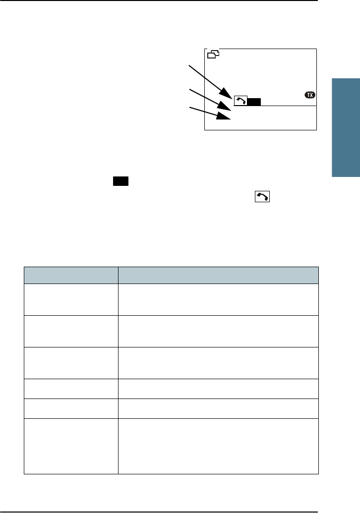
Display for a session
In the DSC window the type of
session, the current state,
MMSI number of the other
party and lapsed time since
the reception of a call request
or an acknowledgment is
shown.
The session state icons, in the
example V and R, show the state of the session:
• ACTIVE — inverted, transmitter tuned into the communication channel
in the example , a DSC Routine call).
• HOLD — normal view, parked session (in the example , VHF voice
communication.
For more information on the session state icons see Session state icons D, U,
S, R and V on page 34.
The session line can be one of the following:
Session line Explanation
OWN DISTRESS The ship is in own distress. See also To send a
distress message on page 21.
DISTRESS RX You watch or participate in a distress
communication for another station in distress
RELAY calls
(numerous)
You watch or participate in a distress
communication for another station in distress
ALL SHIPS TX/RX You have sent / received an all ships call
GROUP TX/RX You have sent / received a group call
INDIVIDUAL TX/RX You have either sent a call request to a station to
establish contact, or another station has made a
call to you to establish contact. The call needs a
reply.
VIEW
QUIT
INT
INTERSHIP/PORT
67
IN COMMUNICATION
INDIVIDUAL TX
MMSI: 123456789 0:27
R
MORE
Session state
Session line
Session status
R
Chapter 2: Operation
30 DSC calls
The session status can be one of the following:
Soft keys to control DSC sessions
Call or session types vary in control options, and options may also change if a
session changes its state. The following table gives an overview of the DSC soft
key commands available:
TEST TX/RX You either have sent a SAFETY TEST call or have
received a SAFETY TEST call from another station
that needs to be replied.
POSITION TX/RX A position request was either sent or received.
Session status Explanation
WAIT FOR
ACKNOWLEDGE
You made an individual call to a station and are
awaiting a reply to establish connection.
OCCUPIED The DSC transmission mechanism waits until the
DSC channel (70) is free.
TRANSMITTING Transmission of a DSC message is ongoing.
IN COMMUNICATION
WITH
The communication has been established in a
routine call.
ACKNOWLEDGED The call requiring (or not requiring) an
acknowledgement has been acknowledged.
Session line Explanation
Soft key — DSC session Radio function
QUIT Terminates the DSC session
HOLD Puts the DSC session hold if it is active (return to
other non-DSC functions)
ACTIVE Activates the DSC session
VIEW Shows details about the DSC call
Chapter 2: Operation
DSC calls 31
2222
Operation
See also Handling multiple calls — DSC and voice on page 33.
RESEND Transmits an identical call if available
NEWCH Replies with a new channel if an individual call is
received with a communication channel specified
which is not available in the radio, or the operator
decides to change the channel.
UNABLE Constructs a reply to the caller if an individual call is
received which is not compatible with the radio
modes.
SILENT Silences alarms. Any key silences the alarm but this
soft key function will do only this.
ACK Acknowledges a received call request with the
suggested parameters.
POS (Own Distress) A shortcut to own position data information.
PAUSE (Own Distress) Pauses the automatic repetition of distress
transmissions
RESUME (Own
Distress)
Resumes automatic repetition of distress
transmissions (if paused)
DIST ACK Distress acknowledgement.
DROBOS Distress Relay on behalf of someone else.
ANNUL (Cancel Own
Distress)
Cancels an inadvertently transmitted distress
CONFIRM (Cancel Own
Distress)
Confirms action and proceed sequence, used in
cancel distress procedure
INFO (in Cancel Own
Distress)
Turns page of text message.
HIST (Received
distress)
A filtered version of the log displaying received calls
relevant to the current distress event.
Soft key — DSC session Radio function
Chapter 2: Operation
32 DSC calls
Detail information for DSC sessions (soft key: INFO)
A DSC session is updated based on DSC calls received or transmitted. Press the
soft key VIEW to show the details for the current session. For distress events a
sequence of calls may contribute to the complete view and status of the
session. Detailed fields for distress are:
For other session types the soft key function INFO typically shows the details
from a single call. Detail fields for other calls than distress are:
INFO — DSC Explanation
DISTR-MMSI The vessel in distress
NAT Nature of Distress
LAT Latitude position of station in distress
LON Longitude position of station in distress
POS UTC Time of position
MODE Communication mode (Simplex/Semi-duplex Telephony
supported)
INFO —other calls Explanation
CALL Type (on received call) – This may be shown on call reception
CAT Category of the call: Urgency, Safety or Routine
FROM The initiator of the call
TO The intended receiver of the call (unless All Ships)
MODE Communication mode (Simplex/Semi-duplex Telephony
supported)
CHANNEL Subsequent communication channel
LAT Latitude position returned upon a position request
LON Longitude position of station in distress
POS UTC Time of position
Chapter 2: Operation
Handling multiple calls — DSC and voice 33
2222
Operation
Receiving DSC calls
If the radio is in stand-by mode, i.e. not engaged in another session, and a
DSC call is received the call details are shown on the display.
After having silenced the alarm you can
acknowledge the call, put it on hold or display
more information. If you put the call on hold,
the session icon for this call will flash until
you have acknowledged the call.
Handling multiple calls — DSC and voice
The SAILOR 6222 VHF DSC can control multiple DSC sessions simultaneously
with a VHF communication session. All sessions can keep track of their session
state and the communication channel used. They are handled in their
respective sessions, in the order as they are started up.
You can toggle between the
ongoing calls/sessions, that means
that a call — or session — can be on
hold or active. If there are several
calls ongoing, they are shown in
the display with their respective
state (active, on hold, requiring
attention). Use the soft key to
leaf through all ongoing calls or
sessions. The DSC sessions on hold
can receive calls that are pertinent to the session, even when the session is
not displayed.
The example on this page shows that two sessions are ongoing, the inverted R
is a routine DSC call (active), is a non-DSC initiated voice
QUIT
HOLD
VIEW
MORE
INT
19
COMM WITH 123456789
GROUP RX
0:12
RS
PORT-PUBLIC
Note
Note that there is only one active session at a time. The active
session controls the radio transmitter.
QUIT
ACTIVE
MORE
INT
10
CHANNEL: 10
VOICE COMM
R
PORT-PUBLIC
Session
icons
Multiple sessions
Chapter 2: Operation
34 Phone book
communication (on hold). Press the soft key ACTIVE to make the voice session
active and put the DSC call session on hold.
Session state icons D, U, S, R and V
Session icons in the session view inform you of the category of the DSC call or
Voice communication:
•D — Distress
• U — Urgency
•S — Safety
• R — Routine
• V — Voice (VHF voice call, non-DSC)
Phone book
Use the phone book when making a DSC call. You can enter up to 200
contacts. A contact has the following details:
• Name (up to 20 characters)
•Type (SHIP, GROUP or COAST STATION)
•MMSI number
• Channel
• Position Auto Acknowledge (yes or no) or Listen to Group
The phone book is always sorted alphabetically by contact names. Use the soft
key FILTER to toggle between CONTACTS - ALL, COAST, SHIP or GROUP. After
having selected a contact, the phone book closes automatically.
State of session icon Meaning for the current call (DSC or voice)
(inverted) Active call/session
Call on hold
R
R
Chapter 2: Operation
Phone book 35
2222
Operation
Using the phone book to make a DSC call
To call a contact in the phone book do as follows:
1. Press the soft key CALL. If it is not in the display, press the soft key MORE
until CALL appears. The DSC call composer is shown in the display.
2. Press the soft key PHBOOK.
3. Turn the selector knob to scroll to the phone book entry that you want to
call, press the selector knob to select the contact.
4. Press the soft key SEND to make the call.
Adding a contact to the phone book
To add a contact to the phone book do as follows:
1. Press the soft key PHBOOK. If it is not in the display, press the soft key
MORE until PHBOOK appears in the display.
2. Press the soft key ADD and fill in the details for the new contact.
Contact Description
NAME Enter the name by turning the selector knob to the
desired letter, press the selector knob to accept the
letter and advance to the next letter. To finish press
the soft key OK.
TYPE Press and turn the selector knob to select SHIP,
GROUP or COAST STATION.
MMSI Turn and press the selector knob to enter the contact’s
MMSI number (9 digits), press the soft key OK to
accept. For coast station contacts you can also enter a
DSC channel.
Ch (optional) Press and turn the selector knob to select the
preferred channel for this contact, press the soft key
OK.

Chapter 2: Operation
36 Phone book
3. Press the soft key SAVE to save the contact information.
4. Press the soft key EXIT to leave the phone book.
Editing a contact
1. Press the soft key PHBOOK. If it is not in the display, press the soft key
MORE until PHBOOK appears.
2. Press the soft key EDIT.
3. Press and turn the selector knob to browse through the details of the
contact and continue as described in Adding a contact to the phone book
from step 2 onwards.
Deleting a contact
1. Press the soft key PHBOOK. If it is not in the display, press the soft key
MORE until PHBOOK appears.
2. Turn the selector knob to browse to the contact you want to delete.
3. Press the soft key MORE until DELETE appears.
4. Press the soft key DELETE.
5. Press EXIT to leave the phone book and return to VHF operation.
Position Auto Ack For SHIP or COAST STATION: Press and turn the
selector knob to select YES or NO for this contact,
press the soft key OK. This will allow auto-ack of
position requests for this contact.
Listen to Group Still in? For GROUP: Press and turn the selector knob
to select YES or NO for this contact, press the soft key
OK. The radio will respond to calls to the specified
group.
Contact Description

Chapter 2: Operation
Replay function 37
2222
Operation
Replay function
Replay allows the operator to playback received voice messages in the
loudspeaker. Recording is activated automatically when a signal is received.
Recording is not possible during playback. Up to 60 tracks or 240 seconds can
be handled. During a power cycle the recorded tracks are deleted.
The recorded channel is displayed. The message length is shown in seconds.
The display shows how old the message is. If the 240 s storage limit is
reached, the oldest data is overwritten.
Replaying recorded messages
Press the Replay button (short press). The latest message
(message) is repeated. Information about this message is
shown in the display.
To stop replaying the message press the soft key STOP.
To rewind through the recorded messages make a long press on the Replay
button.
To stop replaying a message press STOP or the PTT button on the speaking
device.
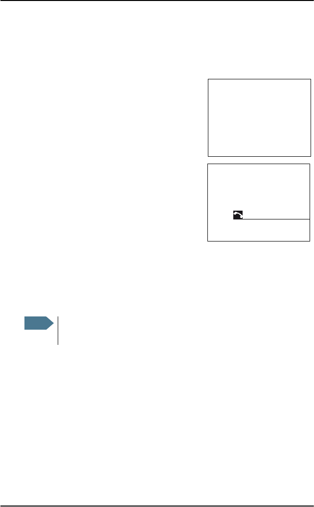
If a signal is received while in replay mode the display shows in the
display.
Note
The replay function can be started even in a distress situation. If a
DSC call is received the replay function continues the playback.
Acknowledgement of the DSC call immediately initiates and activates
the DSC session. You can initiate replay again from any session
afterwards.

Chapter 2: Operation
38 Setup
Setup
The following setup pages are described in this section of the manual:
•Radio setup
•Channel setup
•Power Supply
•DSC setup
•DSC call logs
•System setup
•Controller setup
Accessing a setup page
To change a setting in one of the SETUP pages, do as follows
1. Press the soft key SETUP. If it is not in the display, press the soft key MORE
until SETUP appears.
2. Press the arrow soft key or to advance to SETUP page you want to
edit.
3. Turn the selector knob to go to a setting, then press the selector knob to
change the setting.
4. Press EXIT to return to normal radio operation.
Chapter 2: Operation
Setup 39
2222
Operation
Radio setup
Para-
meter Description
Scan
Hang
Time
Scan hang time, in seconds on an active receiving working channel. The
time is measured from the signal is detected. The radio remains on the
channel for the set time interval, if a signal was detected.
OFF: Resumes scanning when signal disappears (default)
4, 6, 8, 10: Hang time in seconds.
Scan
Resume
Scan resume time, in seconds. When the programmed time of inactivity
has elapsed, and when watch/scan has been aborted using a press on
PTT, or after power-up, scan or watch is resumed.
OFF: Automatic resume is deactivated (default)
3, 6, 10, 15, 20, 25, 30: Resume time in seconds.
Watch
Mode
DUAL: Dual watch monitoring the working channel and the priority
channel (channel 16, default for international channels).
TRIPLE: Triple watch. The working channel is watched with the priority
channel (channel 16) and the programmed call channel (if any,
otherwise dual watch).
Priority
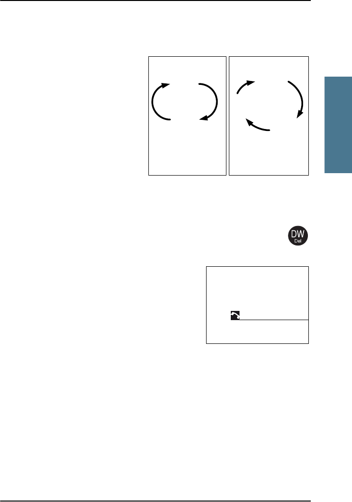
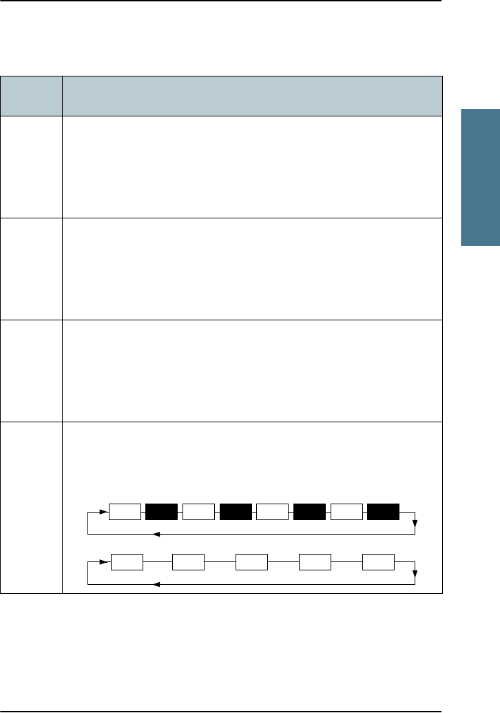
Scan
ON: All channels tagged for scanning are scanned while monitoring
channel 16. (default).
OFF: Only the channels tagged for scanning are scanned in sequence,
not channel 16, unless it is tagged for scanning.
Priority scan: On
Channel
16
Channel
16
Channel
16
Channel
01
Channel
02
Channel
03
Channel
04
Channel
16
Priority scan: Off (normal scan)
Channel
01
Channel
02
Channel
03
Channel
04
Channel
05

Chapter 2: Operation
40 Setup
ATIS code The ATIS code (Automatic Transmitter Identification System) is used for
identification to marine coast and inland stations and its use is
mandatory in a number of European inland waterways such as e.g. the
river Rhine. Like the MMSI number the ATIS number is issued by the
relevant authority.
ATIS for foreign leisure crafts: For ships coming from states which are
not member of the Regional Arrangement the ATIS-Code is based on
the MMSI with a 9 as the first digit.a
Note: The ATIS number can be programmed once. If a wrong number
has been entered and stored, or if there is a requirement to change it,
contact your authorized dealer.
a. The Committee Rainwat in its 12.Meeting (October 2008) decided to change the
building rules of the ATIS code for vessels coming from a country outside the RAINWAT
arrangement.
Para-
meter Description
Chapter 2: Operation
Setup 41
2222
Operation
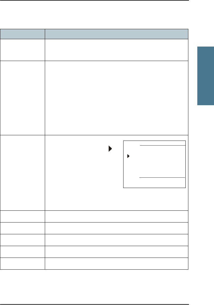
Channel setup
Parameter Description
Channel Mode To select the channel table for the primary channel. Channel
tables available: INT, BI, US, CA, ALT. See also VHF channel
table on page 17.
Bandwidth Selection of the bandwidth for the fixed pre-programmed
channels. This is recommended from Radio Regulations:
Wide: Wide band is 25kHz channel bandwidth (default)
Narrow: Narrow band defines a channel bandwidth of 12.5kHz
Channel number display in narrow band mode:
•2xx if the new frequency is between the original frequency
in wideband mode
•4xx if the new frequency is the same as the original
frequency in wideband mode
INT. Channels You can view the channel
settings. Press the soft key to
advance the channel numbers.
Bandwidth: WIDE (default) or
NARROW
Tagged for scan: OFF (default) or
ON
For customizing, contact your authorized dealer.
Press the soft key EXIT to return to CHANNEL SETUP.
BI. Channels As described above.
US. Channels As described above.
CA. Channels As described above.
ALT. Channels For customizing, contact your authorized dealer.
Private Channels For customizing, contact your authorized dealer.
EXIT INT. Channels
10
PORT-PUBLIC
Ch: 1
Rx: 160.6500 MHz
Bandwidth:WIDE
Tagged for scan: OFF
Tx: 156.0500 MHz
Chapter 2: Operation
42 Setup
Power Supply
DSC setup
Parameter Description
Monitor Set this to ENABLED if the radio is connected to a SAILOR 6081 Power
Supply Unit and Charger.
Set this to DISABLED for any other power supply.
Status Visible if ENABLED. Current status of the connected power supply.
Voltage Visible if ENABLED. Current voltage.
Current Visible if ENABLED. Current current.
DSC setting Description
Position & MMSI Available position information.
Here you can enter position data and UTC time manually. See
also Position and MMSI number on page 12 for a step-by-step
description.
DSC Groups Shows DSC groups. You can also add, edit, filter and delete
groups here.
Auto-Ack Test Auto-acknowledgement of test DSC messages.
OFF or ON (default)
Auto-Ack Polling Auto-acknowledgement of polling DSC messages.
OFF or ON (default)
Auto-Ack Position Auto-acknowledgement of position DSC messages.
OFF (default) or ON
Auto-Ack Individual Auto acknowledgement of individually addressed, non
distress DSC messages
OFF or ON (default)

Chapter 2: Operation
Setup 43
2222
Operation
Non-Distr. Inactivity Inactivity time-out to exit non-distress functions (e.g. in
setup) without automatic time-out (OFF):
Range: OFF, 1 to 30 minutes, in 1 min. steps
Default: 15min.
Distress Inactivity Inactivity time-out for received distress DSC automated
procedures without automatic time-out:
Range: OFF, 1 to 30 minutes, in 1 min. steps
Default: OFF
Comm Inactivity Inactivity time-out of non DSC communication (VHF).
Range: 10 to 600 seconds, in 10 s steps
Default: 30sec
Non-Distr.Alarms Non-distress DSC alarms
OFF: Disabled
ON: Enabled (default)
Medical transport ON: This option is available in DSC calls of the type Urgency.
OFF (default)
Neutral crafts ON: This option is available in DSC calls of the type Urgency.
OFF (default)
Print DSC For printing of DSC messages on a printer connected to the
system.
ON or OFF: (default)
DSC Self Test You can set the radio to run a DSC self test.
OFF: Disabled (default)
RUN: Run test.
For further details about this test see DSC routine testing on
page 50.
DSC setting Description
Chapter 2: Operation
44 Setup
DSC call logs
Use the soft keys and to leaf through all logs.
System setup
DSC call log Description
Received Distress Shows a log of up to 20 received distress calls.
Transmitted Calls Shows a log of up to 20 transmitted calls.
Received Calls Shows a log of all received non distress calls.
SYSTEM SETUP Description
System time & Date View and set system time and date
Inactivity timeout Inactivity time-out to exit functions (e.g. in setup) and
return to the application.
Range: 1 to 30 minutes, in 1 minute steps
Default: 10 min.
Language English
Theme Changes the display colour.
BlackOnWhite (default)
WhiteOnBlack
NMEA input (baud rate) 4800 (cannot be edited)
Factory Defaults Resets the radio to factory defaults. Press the selector
knob and confirm the reset to factory default.
Radio Info: SW Version: Software version of the radio
S/N: Serial number of the radio
TU IP: IP address of the radio
Password If you need to change the identity of the radio (MMSI
number or ATIS code), contact your local dealer.

Chapter 2: Operation
Setup 45
2222
Operation
Controller setup
Each of the controlling devices connected and powered has its own setting.
The available settings may vary from controllers applied.
Controlling device Description
Handset 1 vol: Adjust earpiece volume for handset 1: ON, can be adjusted
OFF and from 5 to 100, in steps of 5.
Note: The handset connected to the front connector has top
priority and is configured to ON. The volume can be adjusted
from 0 to 500, in steps of 5.
Handset 2 vol: Adjust earpiece volume for handset 2: OFF, can be adjusted
from 5 to 100, in steps of 5.
Note: If a handset is connected to the rear connector this
value must be configured to a value (1-14).
Ext. speaker FIX: Fixed level is set for external speaker
REL: Relative level following volume adjustment of the
internal speaker
Ext. fixed vol: External speaker fixed volume:
OFF, 5 to 100 in steps of 5
Wheel lock: You can set a time interval after which the SQ, volume and
selector knobs are locked and protected against
unintentional use. Then a lock symbol is shown in the
display. Press any key to unlock the knobs.
OFF, 10s, 20s, 30s, 40s, 50s, 60s
Chapter 2: Operation
46 Setup
Top-level standby soft-key functions and setup pages
DSC SETUP
Handset 1 vol:
Handset 2 vol:
Ext. Speaker
Ext. fixed vol:
Positon & MMSI
DSC groups
Auto-Ack Test
Auto-Ack Polling
Auto-Ack Position
Auto-Ack Individual
Non-Distr. Inactivity
Distress Inactivity
Comm Inactivity
Non-Distr. Alarms
Medical transport
Neutral craft
Print DSC
DSC Self Test
System time & date
Inactivity timeout
Language
Colour theme
NMEA in (baud )
Factory Defaults
Password
Radio Info
Scan Hang Time
Scan Resume
Watch mode
Priority Scan
ATIS code
DSC CALL LOGS
SYSTEM SETUP
RADIO SETUP
CONTROLLER
SETUP
Received Distress
Transmitted Calls
Received Calls
Channel Mode
Bandwidth
Int. Channels
BI. Channels
US. Channels
CA. Channels
ALT. Channels
Private Channels
CHANNEL SETUP
PHBOOK
CALL
SCAN
EXIT
ADD
FILTER
EXIT
PHBOOK
ALERT EXIT
POS
DROBOS EXIT
PHBOOK
SETUP EXIT
SETUP PAGES TOP-LEVEL STAND-BY
EXIT
START
TAG
FILTER
LOCAL
POWER SUPPLY Monitor :

47
Chapter 3
3333
Service & maintenance
Service & maintenance 3
Contact for support
Contact your authorized dealer for technical service and support of the VHF
radio. Before contacting your authorized dealer you can go through the
troubleshooting guide to solve some of the most common operational
problems.
Maintenance
Preventive maintenance
Maintenance of the SAILOR 6222 VHF DSC can be reduced to a maintenance
check at each visit of the service staff. Inspect the radio for mechanical
damages, salt deposits, corrosion and any foreign material. Due to its robust
construction and ruggedness the radio has a long lifetime. Anyway it must
carefully be checked at intervals not longer than 12 months - dependent on the
current working conditions.
Salt deposits
In case the equipment has been exposed to sea water there is a risk of salt
crystallization on the keys and knobs and they may become inoperable. Clean
the VHF radio and speaker microphones with fresh water.
Error messages and warnings
Errors and warning messages are shown in the display and are read-only.
Chapter 3: Service & maintenance
48 Maintenance
DSC self test
To run a control routine DSC self test, do as follows:
1. Press the soft key SETUP. If it is not in the display, press the soft key MORE
until SETUP appears.
2. Press the arrow soft key or to advance to DSC SETUP.
3. Turn the selector knob to select DSC Self Test. Press and turn the selector
knob to select RUN.
The test will check the ability to encode/decode DSC signalling on RF level.
The radio will automatically transmit a DSC safety test call to its own MMSI
number without enabling the transmitter power amplifier. In parallel the
radio decodes and compares the received call to be the same as the
transmitted.
The display shows the result of
the test.
4. Press the soft key OK to
acknowledge the test result and
resume normal operation.
Important
If the DSC loopback test fails, this indicates the DSC
functionality does not work correctly — including the ability to
send a DISTRESS message.
Contact your dealer immediately for further advice.
DSC loopback
test passed
TEST RESULT
DSC loopback
test FAILED
TEST RESULT

Chapter 3: Service & maintenance
Troubleshooting guide 49
3333
Service & maintenance
Troubleshooting guide
Action Symptom Remedy
The radio
will not
turn on
The display
is empty.
Check if power is present.
Check fuse which is placed in the power connector.
Check performance of power supply if connected to
one.
No commu-
nication
The
loudspeake
r is mute.
Check the antenna installation.
Check antenna cable.
Check handset/Handmicrophone and cable.
GPS Position
requested.
If the VHF, despite being connected to a
GPS/position source, prompts for entering the
position and time information, the automated
update has most likely been lost either due to
missing data on the line, broken cabling or the
GPS/position source has failed. Refer to the
installation section in the back of this manual for
installation and connection details.
Until the automatic position update from
GPS/position source is restored position and time
must be entered manually when prompted by a
(four hour) timer in VHF.
In the DSC SETUP, Position Info, you can verity the
position data. If data is present Lat/Lon/UTC will be
displayed.

Chapter 3: Service & maintenance
50 Troubleshooting guide
DSC routine
testing
Check the DSC function regularly. Verify the
complete DSC installation, with antennas, by
transmitting a Safety Test call to another station
(coast or ship). The test call is generated using the
DSC call flow via menu CALL.
The call should normally be replied by the
receiving station without questioning. The default
configuration of a DSC VHF radio is auto-
acknowledgement of any received Safety test call
requests. If a ship is equipped with multiple radios
a second radio can be the station to check up
against. The transmitting radio will not receive its
own transmitted calls.
If there is only a single radio on a vessel, a facility
is built into the unit where the DSC engine can be
verified using a test call that is internally looped
without activating the radio transmitter PA. The
test is executed via menu SETUP, DSC SETUP. The
call sequence that is verified, is an Individual
Safety Test Call directed to own MMSI. The test
status is read in the display.
Missing
MMSI
DSC
operation
is not
working
When powering up the VHF for the first time after
leaving factory there is no MMSI number in the
VHF radio. For the DSC operation to function the
MMSI number must be entered in the VHF radio.
For further details see the installation manual.
Wrong
MMSI
number
If a wrong number has been entered and stored, or
if there is a requirement to change it, contact your
authorized dealer.
Action Symptom Remedy

Chapter 3: Service & maintenance
Troubleshooting guide 51
3333
Service & maintenance
Radio time DSC logs
are sorted
with wrong
time stamp
or radio
time is
incorrect
A wrong radio time indication should occur only if
GPS position source is not connected or providing
correct time data. A valid GPS time signal will
update the UTC time used for time stamping the
DSC logs.
If a GPS/position source is not connected to the
VHF radio and hence position and time is entered
manually, you must enter the "radio time" also
manually, at least after power up. This will ensure
correct time stamping of the DSC logs.
The UTC time is the suggested time to be entered
when prompted for entering position and time
manually (every four hours).
DSC
Channel
not free
DSC
transmissio
n delayed
The transmission of a DSC call which is not of
category distress will be postponed if the VHF radio
is in the process of decoding an incoming DSC call.
As soon as this decoding process has finalized the
transmission will take place.
Handset
configura-
tion
No sound
in earpiece
The earpiece volume may be configured to OFF.
See section Controller setup in the user manual on
how to adjust the earpiece volume of the handset.
Action Symptom Remedy

Chapter 3: Service & maintenance
52 Troubleshooting guide
Device
failure
If any of the checks and tests described in this
section do not assist in resolving the difficulties
experienced in the operation and/or performance
of the VHF installation, a fault may have developed
in the VHF radio itself.
When contacting an authorized Thrane & Thrane
representative be sure to provide as much
information as possible describing the observed
behavior - also including the type of the VHF radio,
its serial number, and software release version
(both found in the setup menu Controller Setup).
WARNING:
POWER
SUPPLY
LOST
CONTACT
Power
supply
status
cannot be
monitored.
In Setup, Power Supply, set Monitor to disabled.
You can only monitor the power supply if the radio
is powered by a SAILOR 6081 Power Supply Unit
and Charger.
Action Symptom Remedy
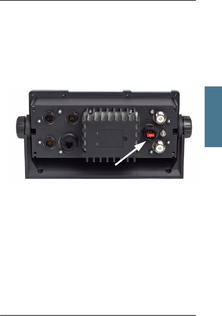
Chapter 3: Service & maintenance
Troubleshooting guide 53
3333
Service & maintenance
Replacing the fuse in the power connector
One fuse is installed in the power connector. If the fuse is blown, do as
follows:
1. Track down why the fuse was blown and solve the problem.
2. Take out the old fuse.
3. Insert the new fuse. The fuse rating is 10 AT.
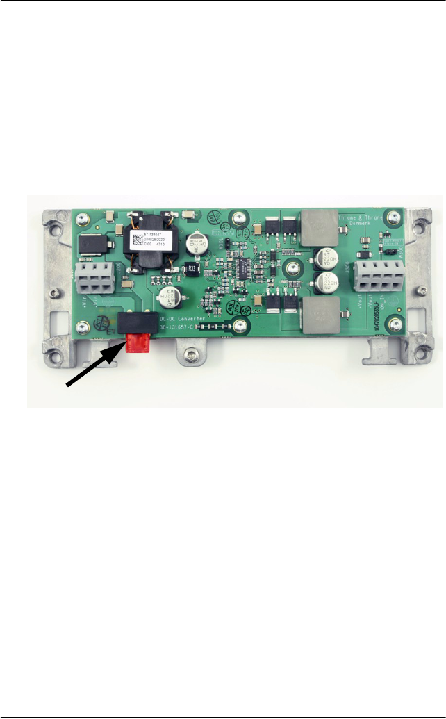
Chapter 3: Service & maintenance
54 Troubleshooting guide
Replacing the fuse in the SAILOR 6090 Power Converter
One fuse is installed in the SAILOR 6090 Power Converter. If the fuse is blown,
do as follows:
1. Track down why the fuse was blown and solve the problem.
2. Take out the old fuse.
3. Insert the new fuse. The fuse rating is 10 AT.

Chapter 3: Service & maintenance
Warranty and returning units for repair 55
3333
Service & maintenance
Warranty and returning units for repair
Should your Thrane & Thrane product fail, please contact your dealer or
installer, or the nearest Thrane & Thrane partner. You will find the partner
details on www.thrane.com where you also find the Thrane & Thrane Self
Service Center web-portal, which may help you solving the problem.
Your dealer, installer or Thrane & Thrane partner will assist you whether the
need is user training, technical support, arranging on-site repair or sending
the product for repair.
Your dealer, installer or Thrane & Thrane partner will also take care of any
warranty issue.
Repacking for shipment
Should you need to send the product for repair, please read the below
information before packing the product.
The shipping carton has been carefully designed to protect the SAILOR 6222
VHF DSC and its accessories during shipment. This carton and its associated
packing material should be used when repacking for shipment. Attach a tag
indicating the type of service required, return address, part number and full
serial number. Mark the carton FRAGILE to ensure careful handling.
If the original shipping carton is not available, the following general
instructions should be used for repacking with commercially available
material.
1. Wrap the defective unit in heavy paper or plastic. Attach a tag indicating
the type of service required, return address, part number and full serial
number.
2. Use a strong shipping container, e.g. a double walled carton of 160 kg test
material.
Note
Correct shipment is the customer’s own responsibility.

Chapter 3: Service & maintenance
56 Warranty and returning units for repair
3. Protect the front- and rear panel with cardboard and insert a 7 cm to 10 cm
layer of shock-absorbing material between all surfaces of the equipment
and the sides of the container.
4. Seal the shipping container securely.
5. Mark the shipping container FRAGILE to ensure careful handling.
Failure to do so may invalidate the warranty.

57
Appendix A
AAAA
Technical specifications
Technical specifications A
Transceiver unit SAILOR 6222 VHF DSC
Item Specification
Weight SAILOR 6222 VHF DSC < 1.50 kg (3.3 lbs) approximately
Box weight
SAILOR 6222 VHF DSC
3.8 kg (8.4 lbs) approximately, including SAILOR
6201 Handset and wall mount cradle,
SAILOR 6090 Power Converter and Installation
and user manual in box.
Dimensions Height: Outer dimension 107 mm, hole height for
flush mount 89 mm
Width: Outer dimension 241 mm, hole width for
flush mount 227 mm
Depth: Outer dimension from front of knobs 132
mm, depth for flush mount 94 mm
Operating temperature -25°C to 55°C (5°F to 131°F)
Storage temperature -30°C to 80°C (-22°F to 176°F)
Power supply 12 VDC Nominal (10,8– 15,6 VDC)
Current consumption Max. 7 A
Current consumption at
12 VDC without any
accessories connected
RX: 0.5 A
TX: 5 A
Current consumption at
12 VDC with all accessories
connected
RX: 0.7 A
TX: 7 A
Appendix A: Technical specifications
58 Transceiver unit SAILOR 6222 VHF DSC
Frequency range TX: 156,000 MHz — 157,425 MHz,
RX: 156,000 MHz — 163.425 MHz
Item Specification
Channel spacing 12.5 kHz and 25 kHz, all international maritime
channels
Number of P channels The radio may be programmed with up to 100
private channels that can be managed in all
channel modes.
Modulation
25 kHz
12.5 kHz
16K0G3E, 16KOG2B (DSC)
8K05G3E
Antenna 50 Ohm antenna, 50 Ohm female SO239 for
PL259 plug
2-antenna operation for VHF and DSC
communication
Water ingress IPx8 and IPx6 all over. For flush-mount
installations a sealing gasket is included in the
delivery.
Transmitter
Transmit power Hi/Lo: 25 W and 1 W
RF output power High: 25 W +0 dB / - 1.5 dB
Low: 1 W +0 dB / - 1.5 dB
RF output power, Canada High: 21 W ±0.75 dB
Low: 0.8 W ±0.75 dB
Frequency error Below 500 Hz
Adjacent channel power Below 75 dB
Item Specification
Appendix A: Technical specifications
Transceiver unit SAILOR 6222 VHF DSC 59
AAAA
Technical specifications
Conducted spurious emission Below 0.25 W
Distortion Below 3%
S/N ratio Better than 46 dB
Receiver
Sensitivity < -119 dBm typically @ 20 dB SINAD CCITT
weighted
LF power Built-in loudspeaker: 6 W (at 5 kHz dev./1 kHz
tone)
External loudspeaker: 6 W / 8 Ohm
Distortion Below 5%
S/N ratio Better than 43 dB
Spurious emissions Below 2 nW
Spurious response rejection More than 74 dB
Intermodulation response More than 73 dB
Co-channel rejection Better than —10 dB
Adjacent channel selectivity More than 74 dB
Blocking level More than 94 dBV
Item Specification
Appendix A: Technical specifications
60 General DSC specifications
General DSC specifications
NMEA data rates and formats
Item Description
DSC operation According to Rec. ITU-R M.541-9 and Rec.
ITU-R M.689-2, EN 300338-2
DSC protocol According to Rec. ITU-R M.493-13 -
Class A
Navigator interface According to IEC 61162-1 GLL, RMC, ZDA,
GGA, VTG, GNS
Symbol error rate Below 1x10⁻² —113 dBm or 0.20 V p.d.
Modulation 1700 Hz ± 400 Hz. 1200 baud
Frequency error Below ± 1 Hz
Residual modulation Below —26 dB
Item Value
61162-1 4800,8,n,1
61162-2 38400,8,n,1

Chapter A: Technical specifications
SAILOR 6090 Power Converter 24—12 V 61
AAAA
Technical specifications
SAILOR 6090 Power Converter 24—12 V
Item Description
Weight 300 g
Dimensions Height: 33 mm
Width: 190 mm
Depth: 85 mm
Operating temperature -25°C to 55°C (5°F to 131°F)
Storage temperature -30°C to 80°C (-22°F to 176°F)
Input voltage 21—32 VDC
Output voltage 12.5 VDC
Output current (max.) 8 A

Chapter A: Technical specifications
62 SAILOR 6090 Power Converter 24—12 V
63
Appendix B
BBBB
Maritime channels
Maritime channels B
International channels (INT)
L) 1 W TX power
*) Channel 87 and 88 became simplex channels following the introduction of
AIS1 at 161.975 MHz and AIS2 on 162.025 MHz.
These are the default channels. Additional narrowband channels can be
enabled, see Channel setup on page 41.
Channels TX RX SIMPLEX DUPLEX Channels TX RX SIMPLEX DUPLEX
MHz MHz Intership Port Port Public MHz MHz Intership Port Port Public
1 156,050 160,650 60 156,025 160,625
2 156,100 160,700 61 156,075 160,675
3 156,150 160,750 62 156,125 160,725
4 156,200 160,800 63 156,175 160,775
5
156 250
160 850
64
156 225
160 825
5
156
,
250
160
,
850
64
156
,
225
160
,
825
6 156,300 156,300 65 156,275 160,875
7 156,350 160,950 66 156,325 160,925
8 156,400 156,400 67 156,375 156,375
9 156,450 156,450 68 156,425 156,425
10 156,500 156,500 69 156,475 156,475
11 156,550 156,550 70 156,525 156,525 DSC DSC
12
156 600
156 600
71
156 575
156 575
12 156,600 156,600 71 156,575 156,575
13 156,650 156,650 72 156,625 156,625
14 156,700 156,700 73 156,675 156,675
15 156,750 156,750 74 156,725 156,725
16 156,800 156,800 Distress and calling 75 156,775 156,775 L)
17 156,850 156,850 76 156,825 156,825 L)
18 156,900 161,500 77 156,875 156,875
19 156,950 161,550 78 156,925 161,525
20 157,000 161,600 79 156,975 161,575
21 157,050 161,650 80 157,025 161,625
22 157,100 161,700 81 157,075 161,675
23 157,150 161,750 82 157,125 161,725
24 157,200 161,800 83 157,175 161,775
25 157
,
250 161
,
850 84 157
,
225 161
,
825
25
157
,
250
161
,
850
84
157
,
225
161
,
825
26 157,300 161,900 85 157,275 161,875
27 157,350 161,950 86 157,325 161,925
28 157,400 162,000 87 157,375 157,375 *)
88 157,425 157,425 *)
Appendix B: Maritime channels
64 US channels
US channels
L) 1 W TX power. Channels 13, 67 and 77 are limited to low transmission
power.
B) Channels 2, 3, 4, 60, 61, 62, 64, 75 and 76 cannot be selected in US mode.
!) Channels 21A, 22A, 23A, 81A, 82A and 83A may be legally used in some
circumstances but not by the general public in US waters.
RX) Only RX: transmissions are blocked.
*) Channels 87 and 88 became simplex channels following the introduction of
AIS1 at 161.975 MHz and AIS2 on 162.025 MHz.
These are the default channels. Additional narrowband channels can be
enabled, see Channel setup on page 41.
Channels TX RX SIMPLEX DUPLEX Channels TX RX SIMPLEX DUPLEX Channels RX
MHz MHz MHz MHz MHz
1A 156,050 156,050 60
B) W1 162,550
2
B) 61 B) W2 162,400
3
B) 62 B) W3 162,475
4
B) 63A 156,175 156,175 W4 162,425
5A 156,250 156,250 64
B) W5 162,450
6 156,300 156,300 65A 156,275 156,275 W6 162,500
7A 156,350 156,350 66A 156,325 156,325 W7 162,525
8 156,400 156,400 67 156,375 156,375
L)
9 156,450 156,450 68 156,425 156,425
10 156,500 156,500 69 156,475 156,475
11 156,550 156,550 70 156,525 156,525
DSC
12 156,600 156,600 71 156,575 156,575
L)
13 156,650 156,650
L) 72 156,625 156,625
14 156,700 156,700 73 156,675 156,675
15B 156,750
RX) 74 156,725 156,725
16 156,800 156,800
Distress and calling 75 B)
17 156,850 156,850 76
B)
18A 156,900 156,900 77 156,875 156,875
19A 156,950 156,950 78A 156,925 156,925
20 157,000 161,600 79A 156,975 156,975
20A 157,000 157,000 80A 157,025 157,025
21A 157,050 157,050
!) 81A 157,075 157,075 !)
22A 157,100 157,100
!) 82A 157,125 157,125 !)
23A 157,150 157,150
!) 83A 157,175 157,175 !)
24 157,200 161,800 84 157,225 161,825
25 157,250 161,850 85 157,275 161,875
26 157,300 161,900 86 157,325 161,925
27 157,350 161,950 87A 157,375 157,375
*)
28 157,400 162,000 88A 157,425 157,425 *)
Appendix B: Maritime channels
CA channels 65
BBBB
Maritime channels
CA channels
L) 1 W TX power. Channels 15, 17, 20, 65, 66, 75, 76 and 77 are limited to 1 W
transmission power.
!) Channels 4A, 6, 19A, 21A, 22A, 61A, 62A, 63A, 67, 72, 73, 81A, 82A and 83A
may be legally used in some circumstances but not by the general public in
CA waters.
RX) Only RX: transmission is blocked.
*) Channels 87 and 88 became simplex channels following the introduction of
AIS1 at 161.975 MHz and AIS2 on 162.025 MHz.
These are the default channels. Additional narrowband channels can be
enabled, see Channel setup on page 41.
Channels TX RX SIMPLEX DUPLEX Channels TX RX SIMPLEX DUPLEX Channels RX
MHz MHz MHz MHz MHz
1 156,050 160,650 60 156,025 160,625 W1 162,550
2 156,100 160,700 61A 156,075 156,075
!) W2 162,400
3 156,150 160,750 62A 156,125 156,125
!) W3 162,475
4A 156,200 156,200
!) 63A 156,175 156,175 !) W4 162,425
5A 156,250 156,250 64 156,225 160,825 W5 162,450
6 156,300 156,300
!) 64A 156,225 156,225 W6 162,500
7A 156,350 156,350 65A 156,275 156,275 L) W7 162,525
8 156,400 156,400 66A 156,325 156,325
L)
9 156,450 156,450 67 156,375 156,375
!)
10 156,500 156,500 68 156,425 156,425
11 156,550 156,550 69 156,475 156,475
12 156,600 156,600 70 156,525 156,525
DSC
13 156,650 156,650 71 156,575 156,575
14 156,700 156,700 72 156,625 156,625
!)
15 156,750 156,750
L) 73 156,675 156,675 !)
16 156,800 156,800
Distress and calling 74 156,725 156,725
17 156,850 156,850
L) 75 156,775 156,775 L)
18A 156,900 156,900 76 156,825 156,825
L)
19A 156,950 156,950
!) 77 156,875 156,875 L)
20 157,000 161,600
L) 78A 156,925 156,925
21A 157,050 157,050
!) 79A 156,975 156,975
21B 161,650
RX) 80A 157,025 157,025
22A 157,100 157,100
!) 81A 157,075 157,075 !)
23 157,150 161,750 82A 157,125 157,125
!)
24 157,200 161,800 83A 157,175 157,175
!)
25 157,250 161,850 83B 161,775
RX)
26 157,300 161,900 84 157,225 161,825
27 157,350 161,950 85 157,275 161,875
28 157,400 162,000 86 157,325 161,925
87 157,375 157,375
*)
88 157,425 157,425 *)
Appendix B: Maritime channels
66 BI channels
BI channels
L) 1 W TX power on channels 6, 8, 10, 11, 12, 13, 14, 15, 17, 71, 72, 74 and 77.
B) Channels 75 and 76 cannot be selected in BI mode.
*) Channels 87 and 88 became simplex channels following the introduction of
AIS1 at 161.975 MHz and AIS2 on 162.025 MHz.
NB! The ATIS function is enabled on all channels.
Dual Watch & Scanning modes are disabled.
Alternative channels
If the radio is used in regions where neither of the four described standard
channels are allowed, a reduced channel table with international channel
designators and frequencies can be made. Contact your local dealer for
programming the alternative channels.
Private channels
Up to 100 licensed private channels for non-DSC purposes may be specified.
For programming the private channels contact your local dealer.
Channels TX RX SIMPLEX DUPLEX Channels TX RX SIMPLEX DUPLEX
MHz MHz Intership Port Port Public MHz MHz Intership Port Port Public
1 156,050 160,650 60 156,025 160,625
2 156,100 160,700 61 156,075 160,675
3 156,150 160,750 62 156,125 160,725
4 156,200 160,800 63 156,175 160,775
5 156,250 160,850 64 156,225 160,825
6 156,300 156,300
L) 65 156,275 160,875
7 156,350 160,950 66 156,325 160,925
8 156,400 156,400
L) 67 156,375 156,375
9 156,450 156,450 68 156,425 156,425
10 156,500 156,500
L) L) 69 156,475 156,475
11 156,550 156,550
L) 70 156,525 156,525 DSC DSC
12 156,600 156,600
L) 71 156,575 156,575 L)
13 156,650 156,650
L) L) 72 156,625 156,625 L)
14 156,700 156,700
L) 73 156,675 156,675
15 156,750 156,750
L) L) 74 156,725 156,725 L)
16 156,800 156,800
Distress and calling 75 B)
17 156,850 156,850
L) L) 76 B)
18 156,900 161,500 77 156,875 156,875
L)
19 156,950 161,550 78 156,925 161,525
20 157,000 161,600 79 156,975 161,575
21 157,050 161,650 80 157,025 161,625
22 157,100 161,700 81 157,075 161,675
23 157,150 161,750 82 157,125 161,725
24 157,200 161,800 83 157,175 161,775
25 157,250 161,850 84 157,225 161,825
26 157,300 161,900 85 157,275 161,875
27 157,350 161,950 86 157,325 161,925
28 157,400 162,000 87 157,375 157,375 *)
88 157,425 157,425 *)

67
Glossary
CCCC
Glossary
Glossary C
A
AIS Automatic Identification System, a short range coastal tracking
system used on ships and by Vessel Traffic Services for identifying
and locating vessels by electronically exchanging data with other
nearby ships.
ATIS Automatic Transmission Identification System
D
DROBOS Distress Relay On Behalf Of Someone else
DSC Digital Selective Calling
E
EPIRB Emergency Position-Indicating Radio Beacon. Distress radio
beacons, also known as emergency beacons are tracking
transmitters which aid in the detection and location of boats,
aircraft, and people in distress.
G
GPL General Public License
GPS Global Positioning System
L
LGPL Lesser General Public License

Glossary
68
M
MMSI Maritime Mobile Service Identity. A series of nine digits which are
sent in digital form over a radio frequency channel in order to
uniquely identify ship stations, ship earth stations, coast stations,
coast earth stations, and group calls. These identities are formed
in such a way that the identity or part thereof can be used by
telephone and telex subscribers connected to the general
telecommunications network to call ships automatically.
P
PTT Push To Talk
T
TU Transceiver Unit
U
UTC Coordinated Universal Time. The International Atomic Time (TAI)
with leap seconds added at irregular intervals to compensate for
the Earth’s slowing rotation. Leap seconds are used to allow UTC
to closely track UT1, which is mean solar time at the Royal
Observatory, Greenwich.
V
VDR Voyage Data Recorder, a data recording system designed for all
vessels required to comply with the IMO’s International
Convention SOLAS Requirements in order to collect data from
various sensors on board the vessel.
VHF Very High Frequency

69
Index
DDDD
Index
Index D
Numerics
16/C, 10, 15
A
acknowledgement, distress, 23
action line, display, 3
activate
scan resume, 39
scanning, 20
watch, 19
ADD, 35
add a contact, 35
adjust
speaker volume, 10
squelch, 14
Alarm Panel
manual, ix
alarm panel
Distress, 24
ALERT, 22
ALT, 66
ALT channel table, 41
ATIS code, 40
change, 44
attenuation control, 18
Auto-Ack
Individual, 42
Polling, 42
Position, 42
Test, 42
B
background sessions
DSC, 33
backlight, 1
dim, 10
bandwidth, 41
Bi, 66
Bi channels, 66
browse channels, 10
C
CA channel table, 41
CA channels, 65
CALL, 35
call
Distress procedure, v
DSC, 20
call log, DSC, 44
cancelling
distress, 23
change
dual and triple watch, 19
channel
add to scan, 20
bandwidth, 41
remove from scan, 20
select, 10, 11
working, 10, 11
channel table
ALT, 41, 66
Bi, 66
CA, 41, 65
INT, 63
PRIV, 41, 66
US, 41, 64

Index
70
channels
Bi, 66
CA, 65
international, 63
primary, 17
private, 17
US, 64
weather, 17
Colour theme, 44
Comm Inactivity, 43
configuration
system example, 7
contact, 47
adding, 35
deleting, 36
editing, 36
control over radio transmitter, 28
controls, front plate, 2
cradle for 6201, installation, 4
D
data rate
NMEA, 60
deactivate
watch, 19
default reset, 44
DELETE, 36
delete contact, 36
dim, 10
display, 3
display colour
change, 44
distress
acknowledgement, 23
cancelling, 23
display, 21
message relay, 25
nature, 21
power failure, 24
received calls, 26
send from alarm panel, 24
time since activation, 21
distress alert, 22
distress button, 21
distress channel, 10, 15
Distress procedure, v
Distress timeout, 43
document number, this manual, i
DROBOS, 13, 25
DSC
background sessions, 33
call log, 27, 44
calls, 20
loopback test, 48
multiple calls, 33
session definition, 28
DSC alarms
non distress, 43
DSC call logs
setup, 44
DSC self test, 43
DSC session, 28
typical display, 29
DSC soft keys, 30
DSC window, 29
dual watch, 39
change to triple, 19

Index
71
DDDD
Index
E
editing a contact, 36
Emergency call sheet, ix
emergency calls, v
engagement status, 18
enter position manually, 12
EPIRB
nature in DROBOS, 25
error messages, 47
F
factory defaults, 44
FILTER, 20
frequency range, VHF, 58
front plate, controls, 2
fuse
Power Converter, 54
VHF radio, 53
G
GPS data, 12
GPS position
display, 12
H
Hand Microphone, 11
handset cradle
installation, 4
hang time, 39
how to replace, 54
I
icons
session state, 29
input
NMEA, 44
installation
cradle for 6201, 4
handset cradle, 4
installation guide, A3, ix
installation manual, ix
Alarm Panel, ix
INT, 63
IP address, 44
IP rating, 58
K
key 16/C, 10, 15
keys on front plate, 2
knob
selector, 2
volume, 2
L
license
software, ii
LOCAL, 18
louder, volume, 10
low power
override, 18
set to 1 W, 18
M
manual, document number, i
maritime channels, 63

Index
72
MAYDAY, v
medical transport, 43
menu, overview, 46
message
replay, 37
MMSI
change, 44
wrong number in the radio, 50
monitor power supply, 42
MORE, 13
multiple calls, DSC, 33
mute
speaker, 14
N
narrow band, 41
nature of distress, 21
neutral crafts, 43
night vision, how to dim, 10
NMEA
data rate, 60
input, 44
Non-dist Inactivity, 43
Non-distr.alarms, 43
O
overriding low power, 18
P
password, 44
PHBOOK, 35
phone book, 34
add contact, 35
delete a contact, 36
edit a contact, 36
position
enter manually, 12
position data
enter manually, 42
position Info, 42
power
fuse, 53
off, 10
on, 10
Power Converter
fuse, 54
power failure
distress, 24
power supply
monitor, 42
Print DSC, 43
priority scan, 39
PRIV, 66
channel table, 41
private channels, 17, 58, 66
PTT button, 15
R
radio call
making, 16
receiving, 15
radio transmitter
control, 33
control over, 28
received distress calls, 26
reduced transmission power, 18
relay
distress message on behalf of
someone else, 25
replay, 1, 37
button, 2
reset to default, 44

Index
73
DDDD
Index
resume time, 39
RF exposure hazards, iv
run
DSC self test, 43
S
safety summary, iv
salt deposits, 47
scan
add channel, 20
hang time, 39
priority, 39
remove channel, 20
resume time, 39
resume, activate, 39
start, 20
selector knob, 2, 10
self test, 48
DSC, 43
semi duplex, 1
serial number, 44
service line, display, 3
session
INFO key, 32
line, 29
soft keys, 30
state icons, 29
status, 30
what is, 28
setup
controller, 45
DSC call logs, 44
overview, 46
parameters, 46
Radio, 39
system, 44
watch, 39
simplex, 1
soft key, 13
ADD, 35
ALERT, 22
CALL, 35
DELETE, 36
DISACK, 26
DROBOS, 13, 25
DSC, 30
FILTER, 20
LOCAL, 18
MORE, 13
OVRIDE, 18
PHBOOK, 35
RELAY, 25
STOP, 37
TAG, 20
WATCH, 19
softer, volume, 10
software license, ii
Software version, 44
speaker volume, 10
speaking devices, 11
specifications, 57
squelch, 14
squelch control, 2, 14
STOP, 37
stop
replaying a message, 37
watch or scan, 19, 20
support, 47
system configuration
example, 7
system setup, 44

Index
74
T
TAG, 20
remove, 20
tagged channels
view, 20
technical data, 57
temperature
operational, 57, 61
storage, 57, 61
theme
colour, change, 44
timeout, 44
Distress, 43
non distress, 43
VHF and other non distress, 43
triple watch, 39
change to dual, 19
U
US, 64
US channel table, 41, 64
Use GPS, 12
UTC time, 3
enter manually, 12
V
VHF
channels, 16
frequency range, 58
volume
louder, 10
softer, 10
speaker, 10
Volume knob, 2
W
warnings, 47
warranty, 55
limitation, iv
WATCH, 19
watch
dual and triple, 19
dual or triple, 39
setup, 39
start, 19
stop, 19
water ingress, 58
weather channels, 17
weight, 57, 61
wide band, 41
working channel, 10, 11