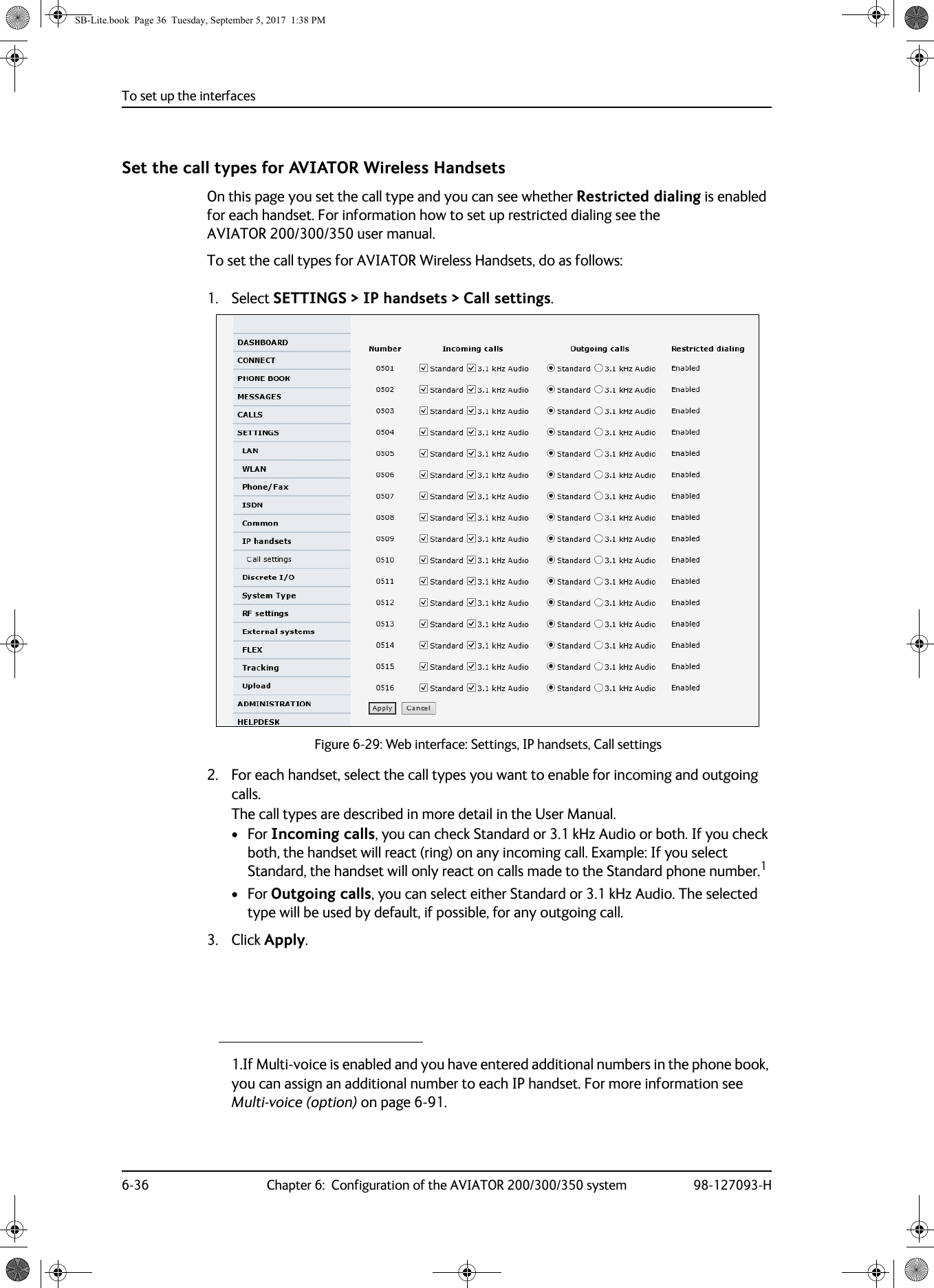
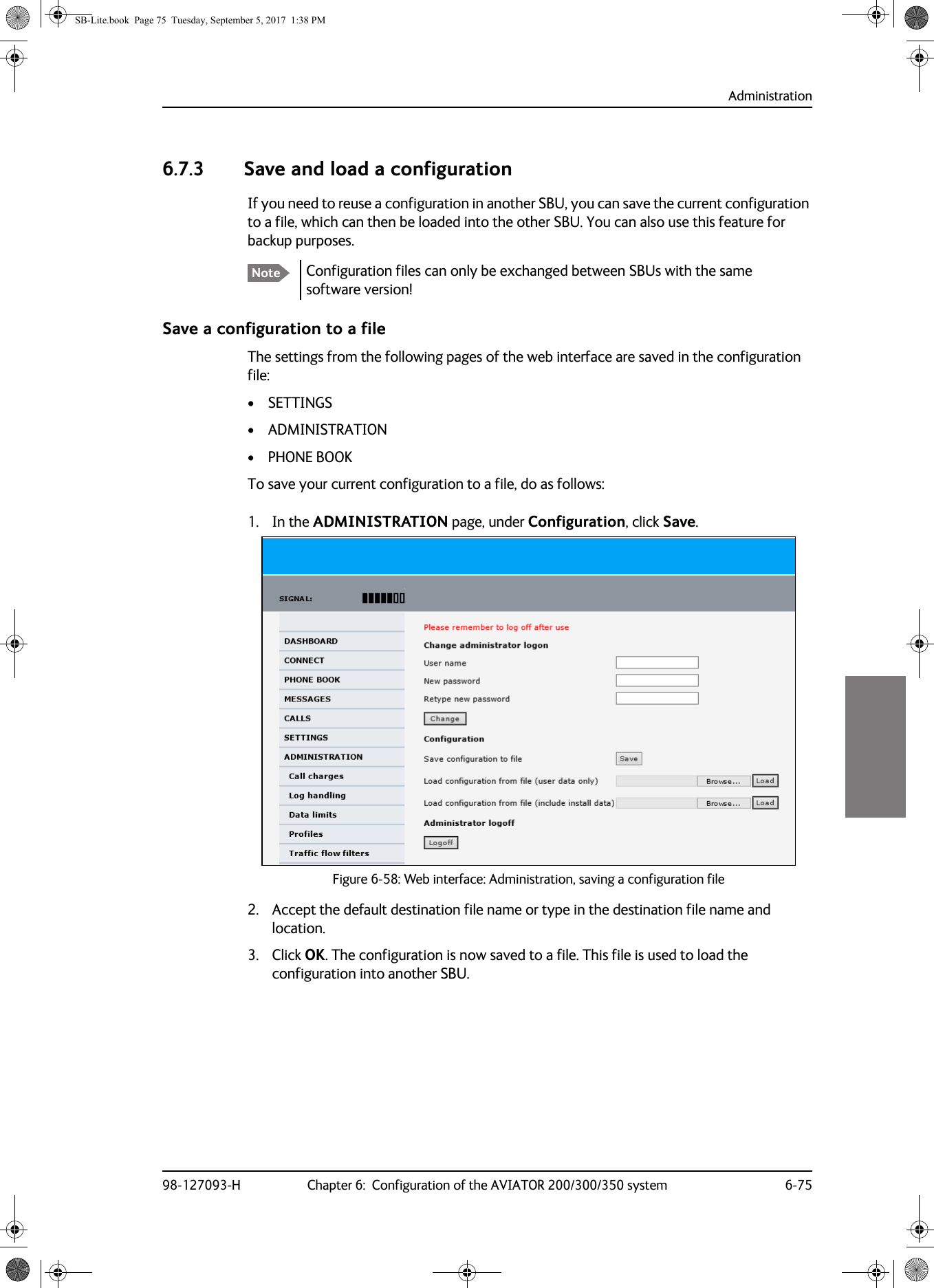
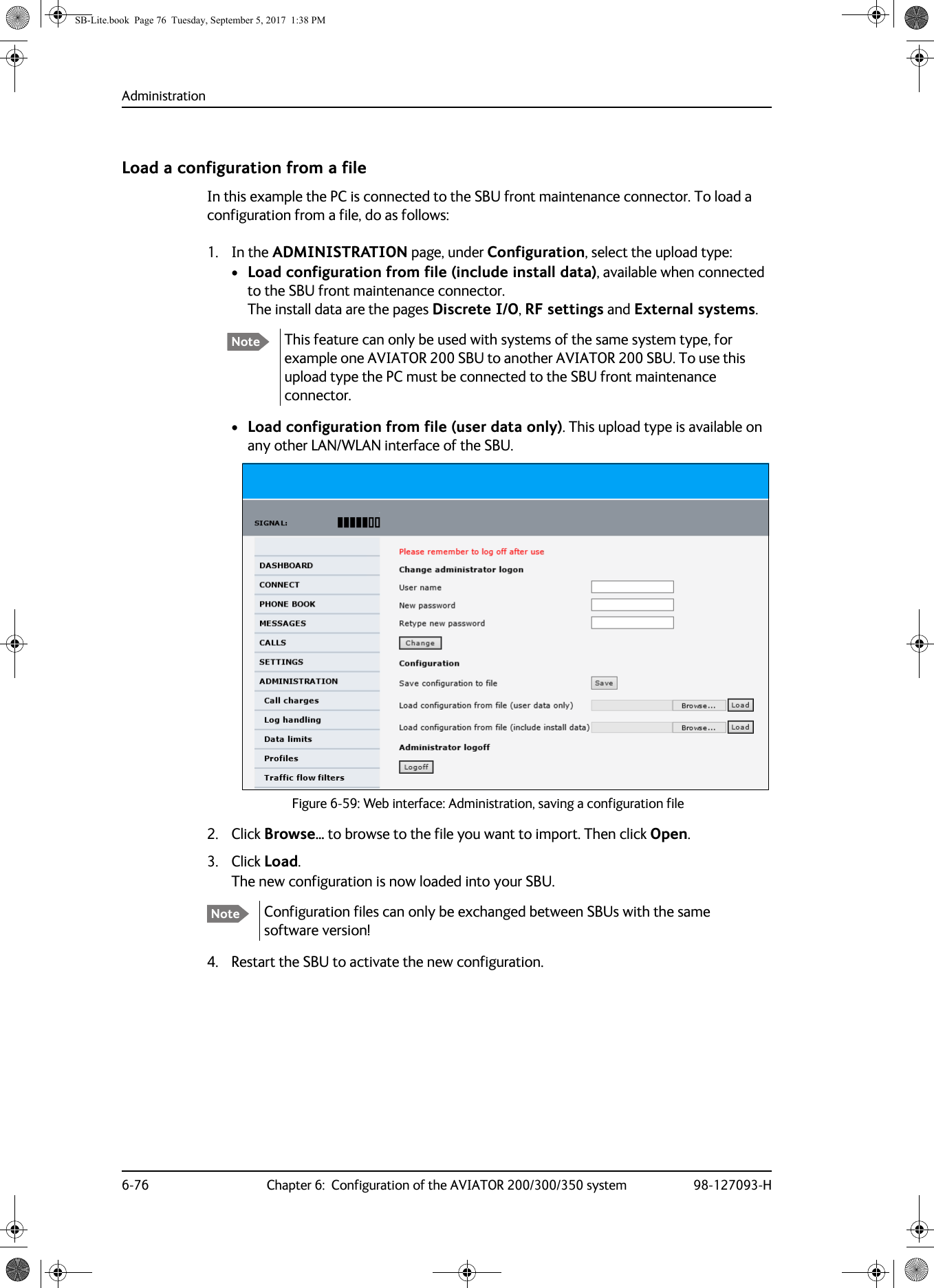
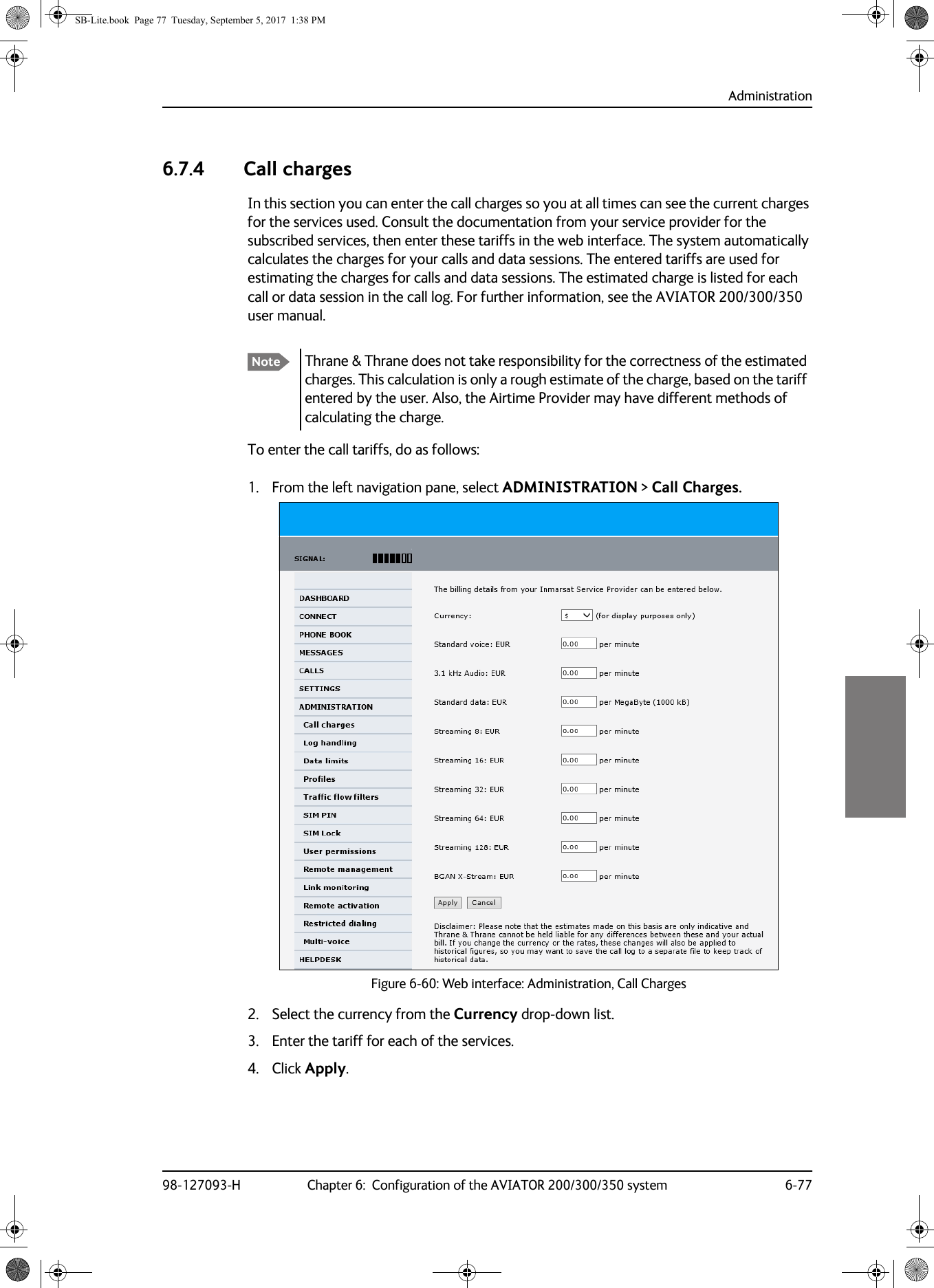
Thrane and Thrane A S AVIATOR Satellite transceiver for Inmarsat Swift Broadband service User Manual
Thrane & Thrane A/S Satellite transceiver for Inmarsat Swift Broadband service
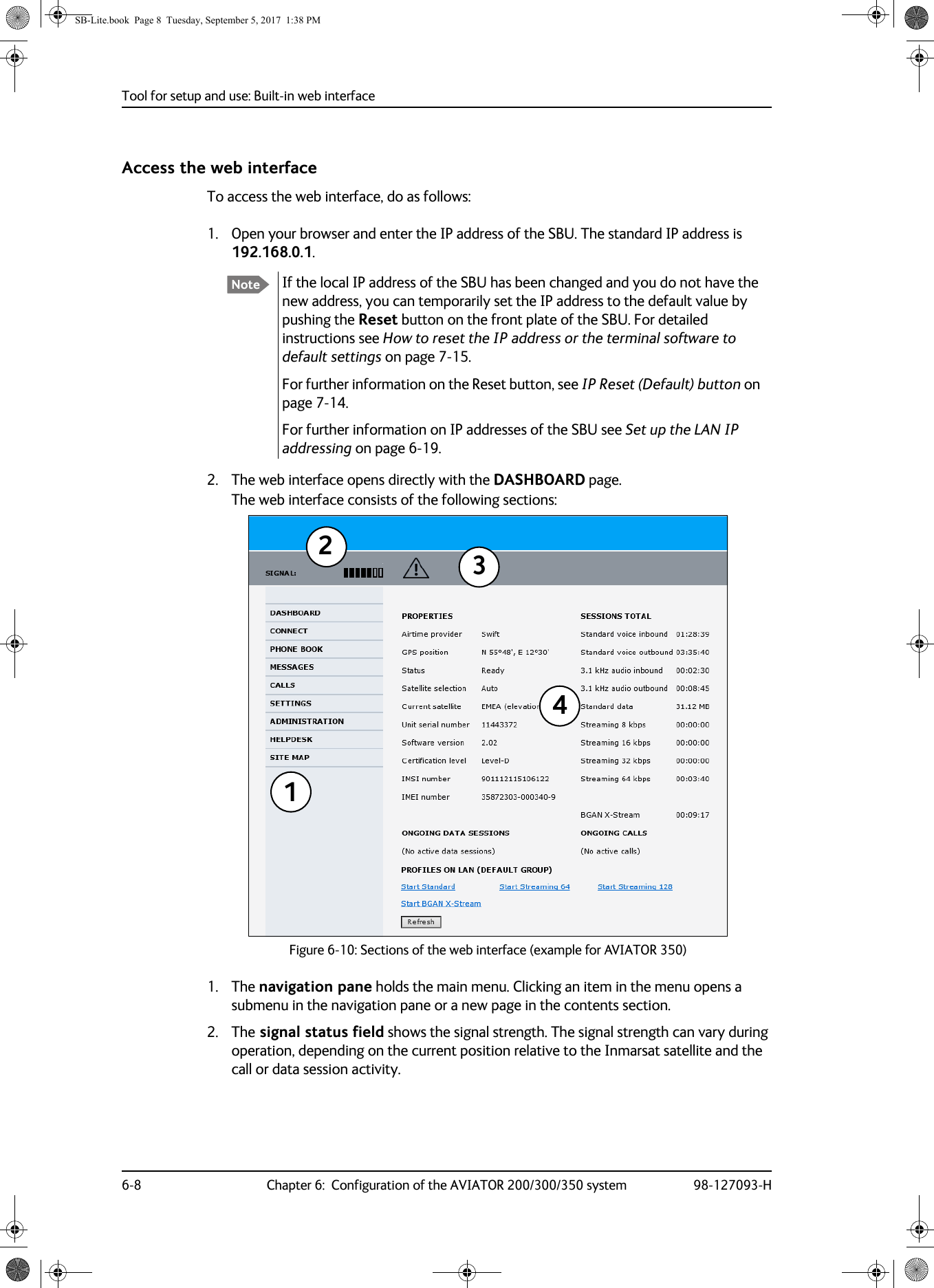
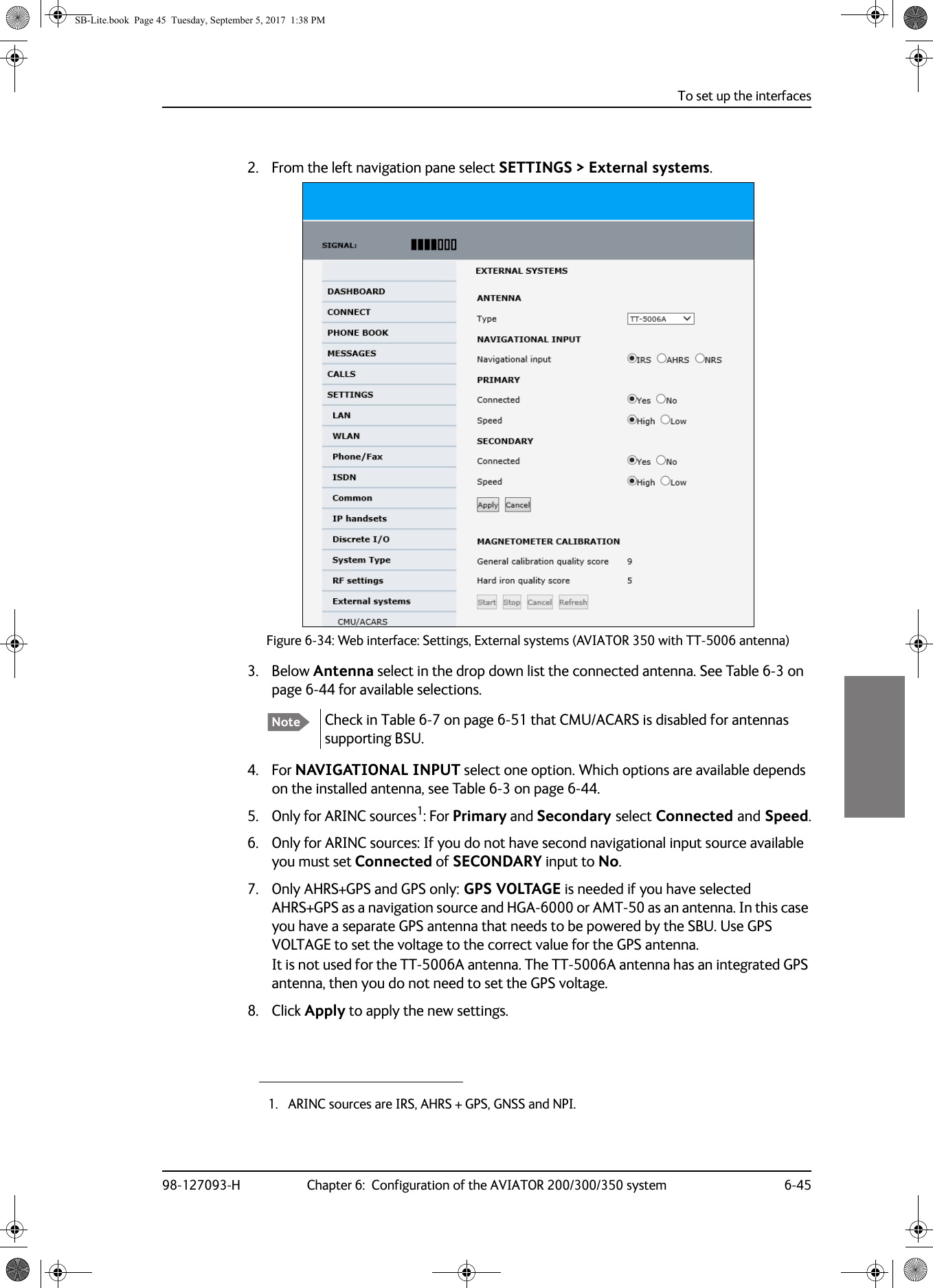
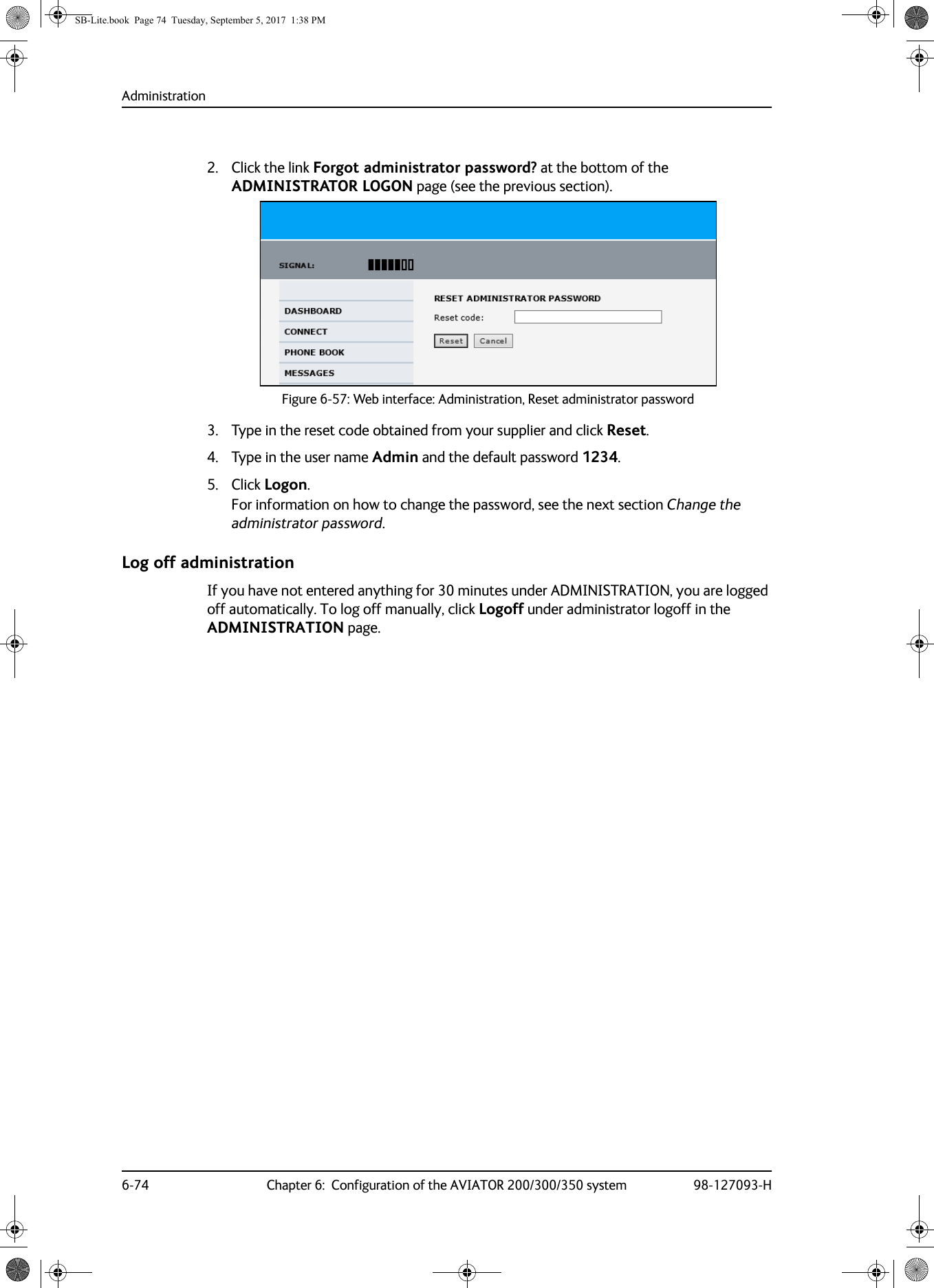
UserManual.wiki
>
Thrane and Thrane A S
>
AVIATOR User Manual
>
Installations Manual
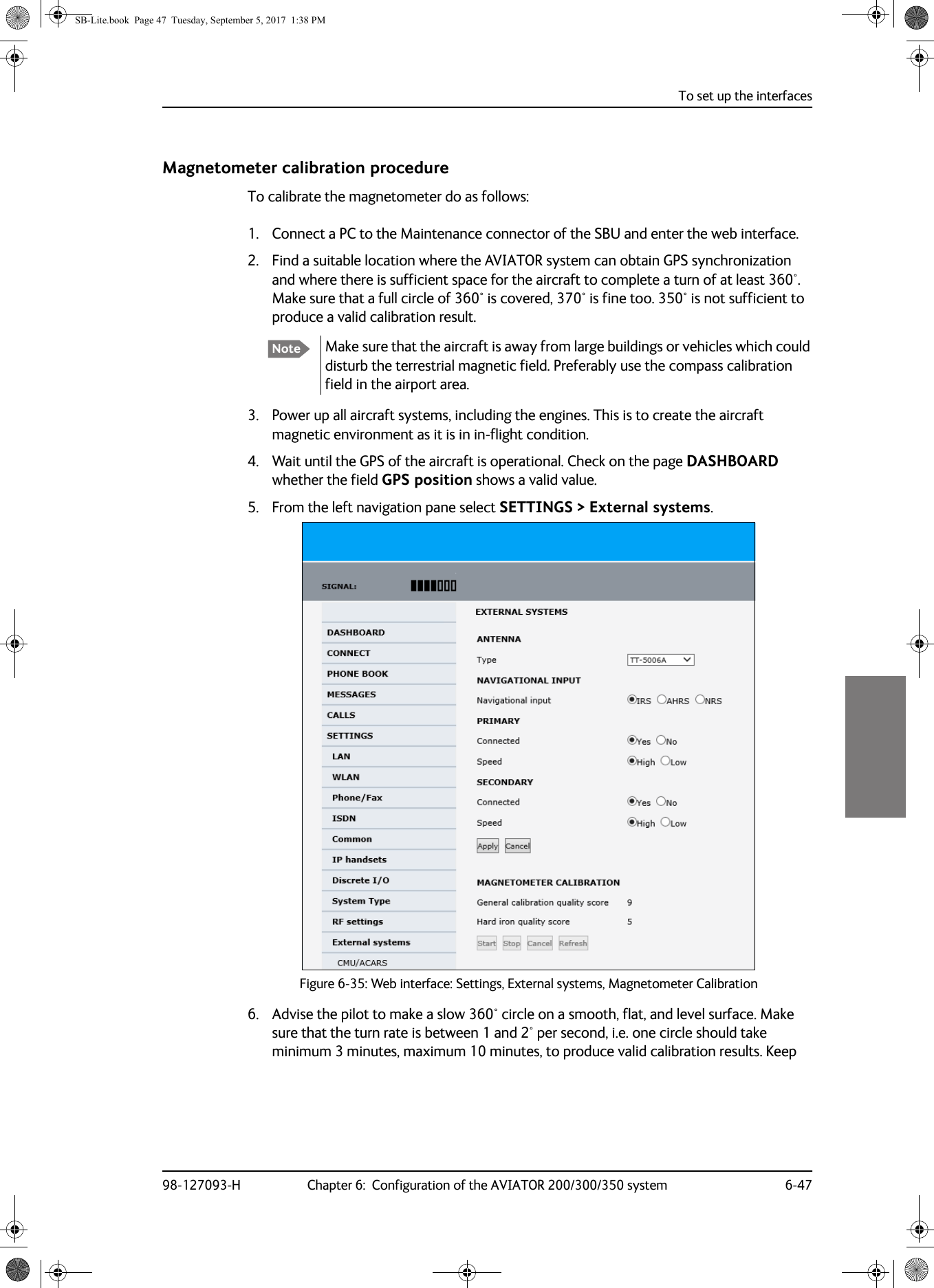
Contents
1.
Installations Manual
2.
Users Manual
Installations Manual
Navigation menu
Upload a User Manual
Namespaces
Wiki Guide
HTML
PDF
Info
Views
User Manual
Discussion / Help
Navigation
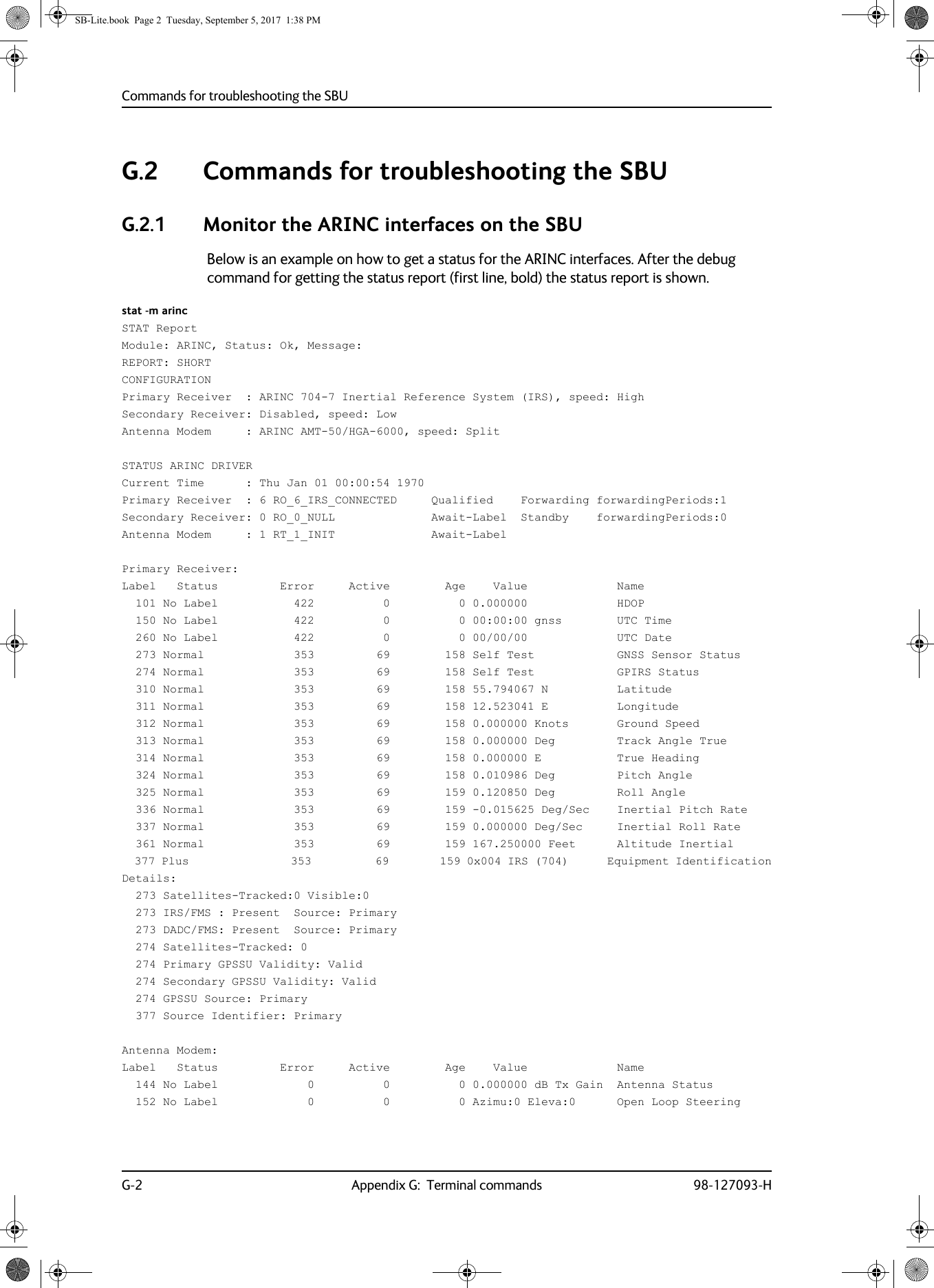
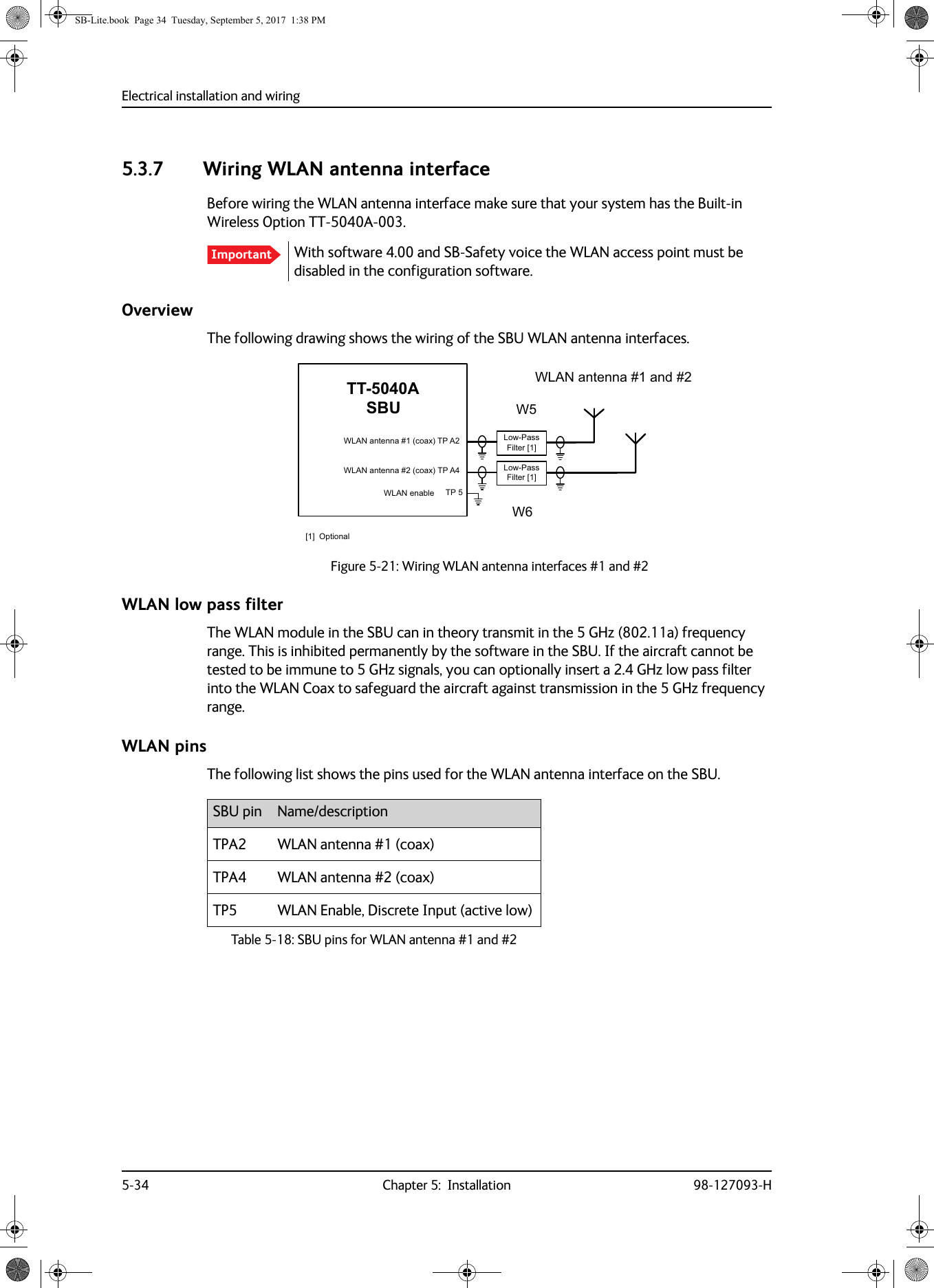
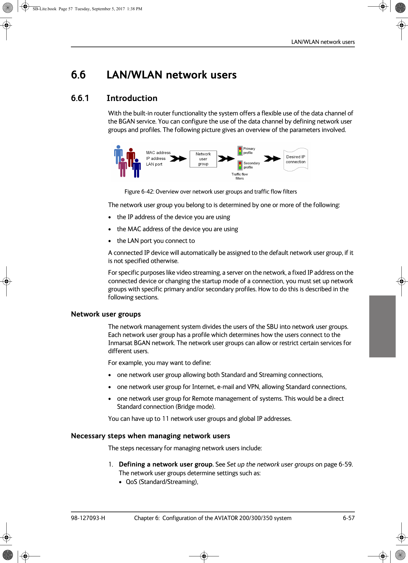
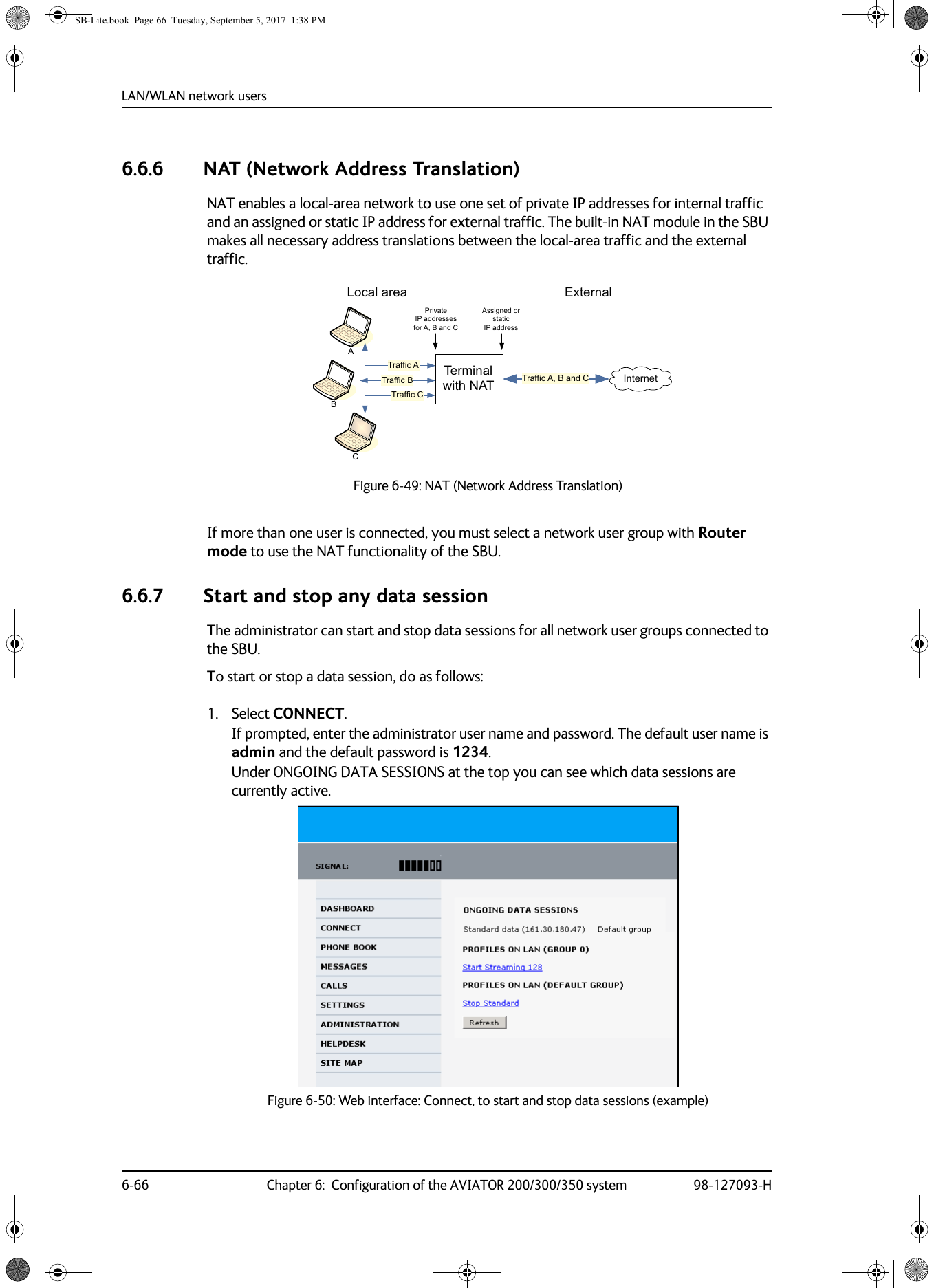
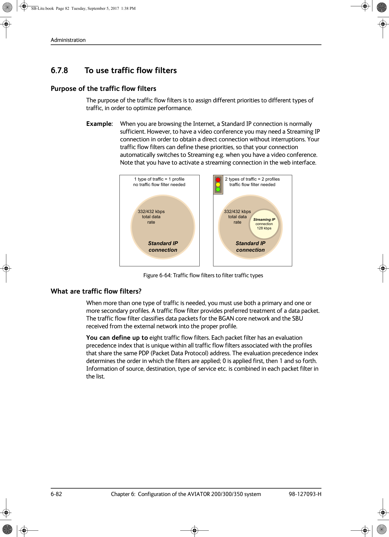
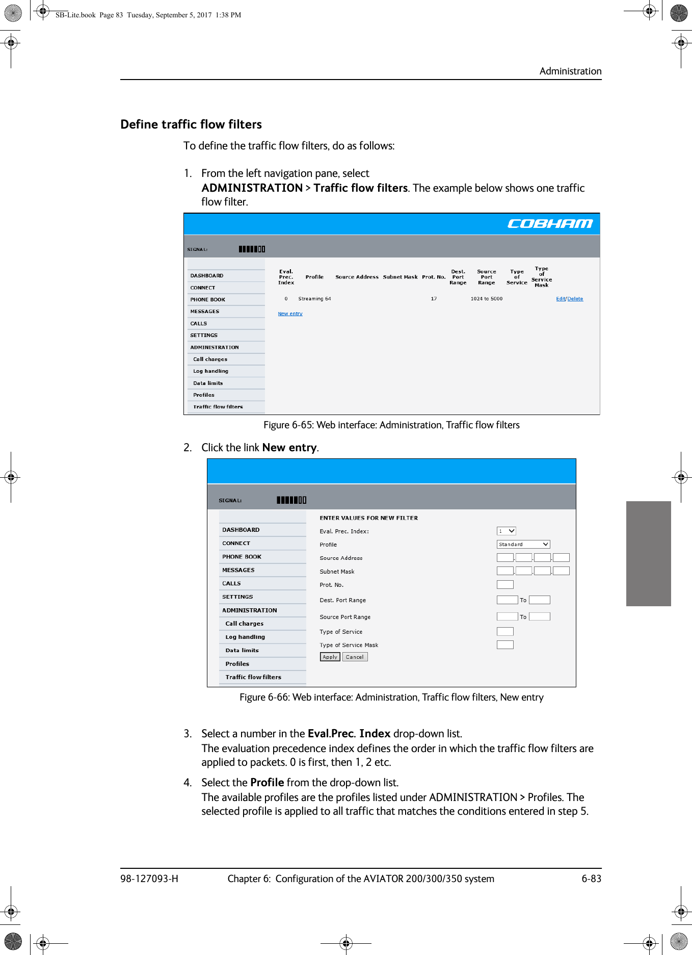
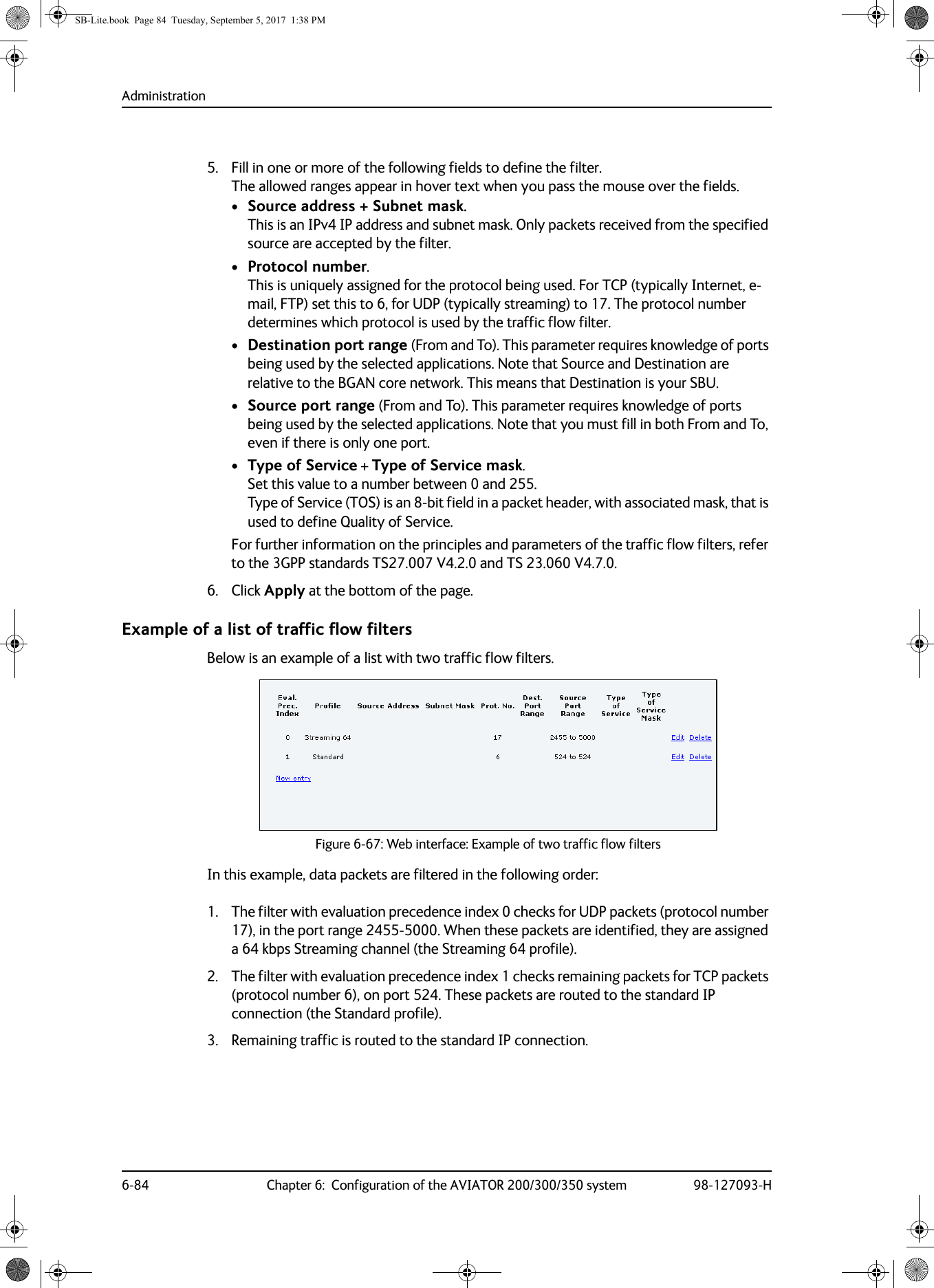
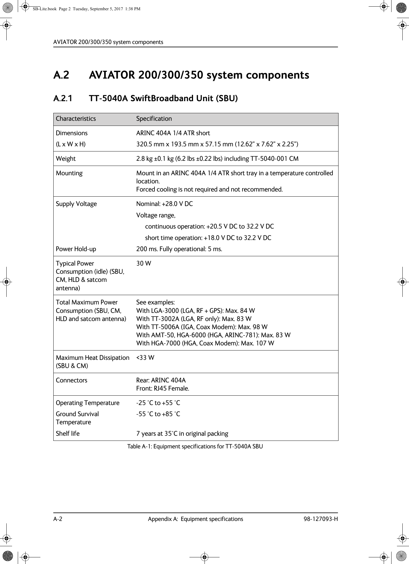
![Application98-127093-H Chapter 2: Introduction to the AVIATOR 200/300/350 2-922222.2 Application2.2.1 Minimum systemA minimum working system has at least:• one TT-5040A SBU• one TT-5040A-001 CM• one TT-5016A HLD• one satcom antenna: LGA, IGA or HGAThe minimum wiring required for an AVIATOR 200/300/350 system is described in the section Minimum system drawing on page 5-2.The CM, HLD and some satcom antennas are powered by the SBU.2.2.2 Part numbersApplicable part numbersThis installation manual is for the AVIATOR 200/300/350 system and is applicable to the part numbers in the following tables.Part number Unit description405040A SwiftBroadband Unit (SBU) [without CM] for AVIATOR 200/300/350405040A-THD SwiftBroadband Unit (SBU) [without CM] for AVIATOR 200D/300D/350D405040A-838 Configuration Module (CM) for SBU for AVIATOR 200/200D405040A-001 Configuration Module (CM) for SBU (no key and no options)405040A-002 Built-in Router option405040A-003 Built-in Wireless option405040A-004 WLAN Antenna, optional (2 pieces recommended)405040A-009 Built-in ACARS/SB Safety (ICAO) voice option405040A-010 Built-in Multi-voice option405040A-006 AVIATOR 350 Key (HGA/IGA)405040A-007 AVIATOR 300 Key (IGA)405040A-008 AVIATOR 200 Key (LGA)Table 2-5: Part numbers SB-Lite.book Page 9 Tuesday, September 5, 2017 1:38 PM](https://usermanual.wiki/Thrane-and-Thrane-A-S/AVIATOR.Installations-Manual/User-Guide-4022359-Page-31.png)
![General installation information5-2 Chapter 5: Installation 98-127093-H5.1.2 Minimum system componentsA minimum working system has at least:• one TT-5040A SBU• one TT-5040A-001 CM• one TT-5016A HLD• one satcom antenna, LGA, IGA, or HGA antenna, see also Satcom antenna systems on page 2-4.The CM, HLD and some satcom antennas are powered by the SBU. The following drawing shows the minimum installation.Minimum system drawingThis drawing is an overview of which units to connect as a minimum.For information on other satcom antenna types supported and wiring of the individual antenna types, refer to the appropriate section of Electrical installation and wiring on page 5-8 and onwards.Figure 5-1: AVIATOR 200 minimum system (example with LGA TT-3002A and GPS antenna)For other navigational input sources see Table 5-2 on page 5-4.Note77$6%877$+/'73$73$;;;%3$*36LQ'&RXW: ::; 77$$QWHQQD/RVVG%#0+]/RVVG%#0+]/RVVG%#0+]G%#0+]'&UHVLVWDQFHȍ5)5[5)7['&3RZHU0RGHP&KDVVLV*URXQG5)5[7[5)5[*36$QWHQQD9'&$LUFUDIW3RZHU6XSSO\,56$+56$$%3,56$+56$%%3,5613,*166RSWLRQDO73*1'3RZHU5HWXUQ739'&3RZHU%3&KDVVLV*URXQG735HPRWHRQRIIQ21736%8(QDEOHSB-Lite.book Page 2 Tuesday, September 5, 2017 1:38 PM](https://usermanual.wiki/Thrane-and-Thrane-A-S/AVIATOR.Installations-Manual/User-Guide-4022359-Page-74.png)
![Mounting considerations98-127093-H Chapter 5: Installation 5-55555The advantage of this system is that it is stand-alone and does not require any interaction with other avionics systems. The disadvantage is that it requires a fairly clean magnetic environment, where the antenna is placed. There may not be any magnetic items such as screws, loudspeakers or DC cables near the antenna. See also Magnetic interference considerations (only for TT-5006A IGA) on page 5-6.Position and velocity information for LGA (AVIATOR 200)The position and velocity information is used for spot-beam selection and Doppler compensation. The following navigational inputs can only be used together with the TT-3002A low-gain antenna, where attitude data are not required:•GPS only: The built-in GPS receiver provides all the necessary navigation data if the SBU receives an RF signal from a GPS antenna on the pin BP A4 of the SBU rear receptacle, bottom plug (see Table 4-3 on page 4-8).•NPI: NPI (Navigation Position Information, a Thrane abbreviation) is similar to IRS but there is no requirement for attitude information. The navigation data can be obtained from other sources than an IRS. Note that the navigation data must be coded exactly as for IRS. For detailed information see Table 5-13 on page 5-27.•GNSS can be used together with the TT-3002A low-gain antenna. Since this antenna does not have any antenna steering mechanisms that must be controlled, the GNSS can provide all necessary navigational data. GNSS is compliant with ARINC-743A [14]. For detailed information see Table 5-14 on page 5-27.Satcom antenna types supportedFor a list of Cobham SATCOM antenna types supported in the AVIATOR 200/300/350 system see Satcom antenna systems on page 2-4.General mounting considerationsRefer to the satcom antenna manual for instructions and details on mounting the antenna. Make sure all requirements in the antenna mounting instructions are met.Place the antenna with unobstructed view to the satellite.Note If possible, always use IRS or AHRS. IRS and AHRS give better precision. Only use NRS as a last option.WARNING! Keep a safety distance of minimum 30 cm (1 ft) for LGA and IGA and 90 cm (3 ft) for HGA to the antenna when the system is transmitting, unless the antenna manual or the specific system configuration presents different requirements. This safety distance ensures that a maximum radiation power density of maximum 10 W/m2 is not exceeded (Recommended by the American National Standards Institute, ANSI/LEEE C95.1-1992).Note The antenna installation must be in accordance with the aircraft manufacturers requirements and/or FAA AC 43.13 - 1B/2A and approved by the appropriate Civil Aviation Authorities.SB-Lite.book Page 5 Tuesday, September 5, 2017 1:38 PM](https://usermanual.wiki/Thrane-and-Thrane-A-S/AVIATOR.Installations-Manual/User-Guide-4022359-Page-77.png)
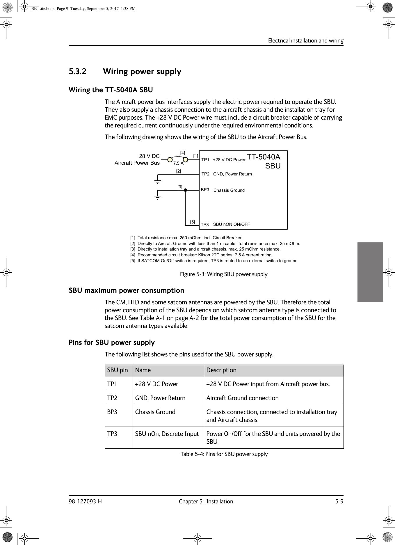
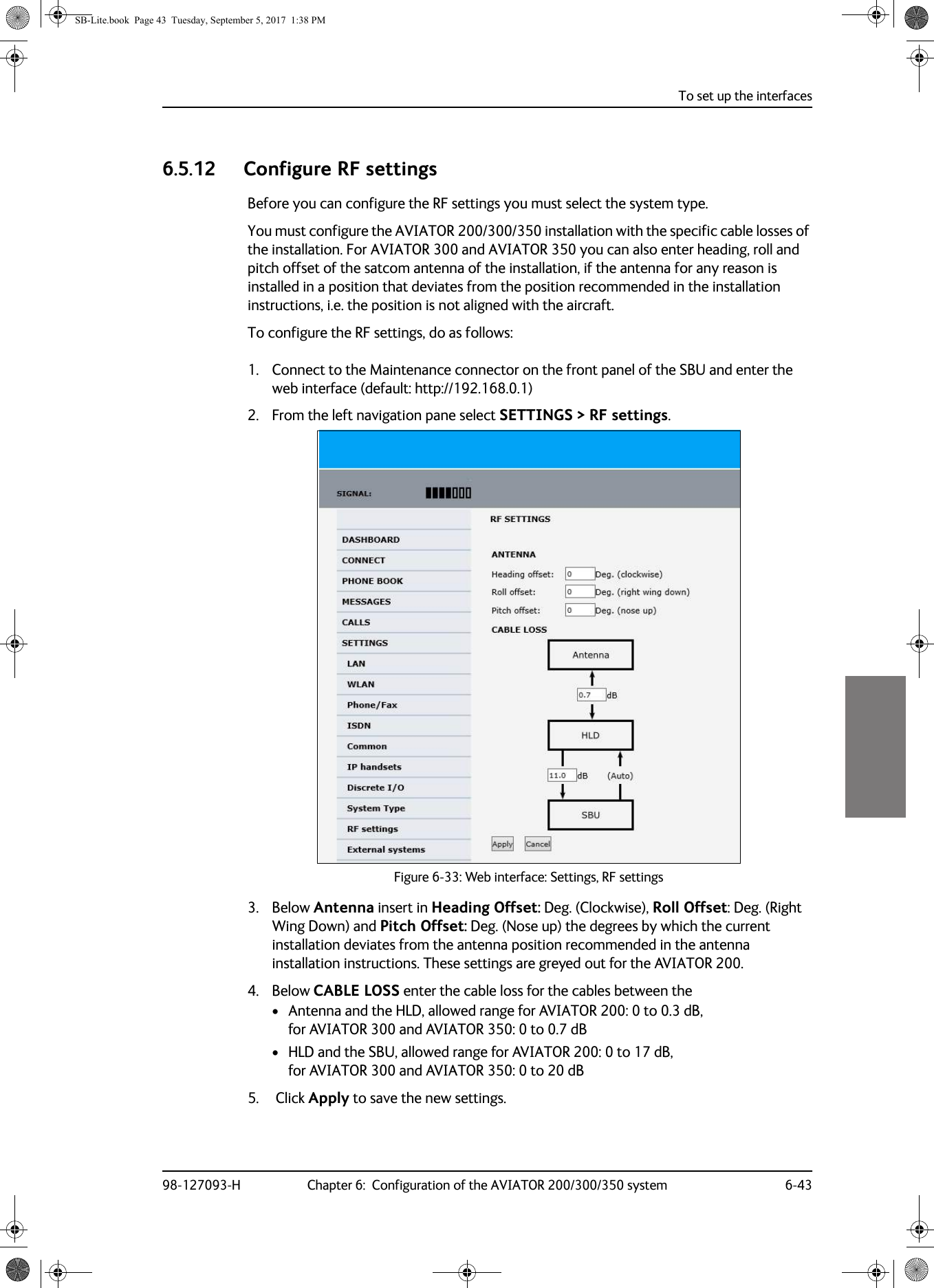
![Electrical installation and wiring5-10 Chapter 5: Installation 98-127093-HDescription of SBU power supply+28 V DC PowerIt is essential to keep the line impedance below the specified limits. See Cable requirements, SBU power supply on page 5-10. Reverse polarity protection is only guaranteed if the suggested circuit breaker is used. A suitable circuit breaker with sufficiently low resistance would be Klixon 2TC series with 7.5 A current rating.Chassis Ground (BP3)The Chassis connection ensures that the SBU cabinet and the installation tray have the same potential, and that there is a connection from the cable shields to the cabinet to comply with EMC requirements.Connect the wire directly to the installation tray and to aircraft chassis.Remote ON/OFF - SBU nON, Discrete Input (TP3)The nON input is used to turn the SBU on and off. Connection of this input to ground turns on the SBU and all units powered by the SBU.The electrical specifications are defined in Description of the discrete types on page 5-44.Cable requirements, SBU power supply5.3.3 Wiring the satcom antennaCable lossesCableaa. The cable numbers refer to the numbers stated on the wiring drawing in the section Figure 5-3: Wiring SBU power supply.Max. resistance Other requirements[1] (+28 V DC Power) 250 m, incl. circuit breaker[2] (GND, Power Return) 25 mThe cable should be as short as possible, max. 1 m.[3] (Chassis Ground) 25 mConnect directly to aircraft chassis.Table 5-5: Requirements to SBU power cablesNote For maximum allowed cable lengths, see Power cables, allowed cable lengths on page 5-47.Note During installation, measure and write down the cable loss of the RF cables. You need these values later on in the web interface during configuration of the system. For further details see Configure RF settings on page 6-43.SB-Lite.book Page 10 Tuesday, September 5, 2017 1:38 PM](https://usermanual.wiki/Thrane-and-Thrane-A-S/AVIATOR.Installations-Manual/User-Guide-4022359-Page-82.png)
![Electrical installation and wiring98-127093-H Chapter 5: Installation 5-115555Wiring TT-3002A LGA/LGA-3000The following drawing shows the wiring for an AVIATOR 200 system using a TT-3002A low gain antenna.For the requirements to RF cables W1, W2 and W3 see Table 5-8 on page 5-23.Figure 5-4: Wiring TT-3002A LGA/LGA-300077$6%877$+/'73$73$;;;%3$*36LQ'&RXW: ::;77$/*$$QWHQQD/RVVG%#0+]/RVVG%#0+]/RVVG%#0+]G%#0+]'&UHVLVWDQFHȍ5)7['&3RZHU0RGHP5)5[5)7['&3RZHU0RGHP&KDVVLV*URXQG5)5[7[5)5[:/RVVG%#0+]>@*36RQO\DYDLODEOHRQ/*$>@SB-Lite.book Page 11 Tuesday, September 5, 2017 1:38 PM](https://usermanual.wiki/Thrane-and-Thrane-A-S/AVIATOR.Installations-Manual/User-Guide-4022359-Page-83.png)
![Electrical installation and wiring5-12 Chapter 5: Installation 98-127093-HWiring TT-5006A IGA/IGA-5001The following drawing shows the wiring for an AVIATOR 300 system using a TT-5006A or IGA-5001intermediate gain antenna.For the requirements to RF cables W1, W2 and W3 see Table 5-8 on page 5-23.Figure 5-5: Wiring TT-5006A IGA or IGA-500177$6%877$+/'73$73$;;;%3$*36LQ'&RXW$QWPRGHP: :::;77$,*$$QWHQQD-EOXH-UHG/RVVG%#0+]/RVVG%#0+]/RVVG%#0+]G%#0+]'&UHVLVWDQFHȍ/RVVG%#0+]5)7['&3RZHU0RGHP5)5[5)7['&3RZHU0RGHP&KDVVLV*URXQG5)5[7[5)5[>@2QO\77$VXSSRUWV156>@7KLVFDEOHPXVWEHZLUHGHYHQLI*36LVQRWXVHG>@>@SB-Lite.book Page 12 Tuesday, September 5, 2017 1:38 PM](https://usermanual.wiki/Thrane-and-Thrane-A-S/AVIATOR.Installations-Manual/User-Guide-4022359-Page-84.png)
![Electrical installation and wiring98-127093-H Chapter 5: Installation 5-135555Wiring HGA-6000 or HGA-6500The following drawing shows the wiring for an AVIATOR 350 system using an HGA-6000 or an HGA-6500 high gain antenna.For the requirements to RF cables W1, W2 and W3 see Table 5-9 on page 5-24.Figure 5-6: Wiring HGA-6000/RVVG%#0+]G%#0+]'&UHVLVWDQFHȍ:::77$+/'+*$$QWHQQD;77$6%8$7[$5[73$73$;;7[0RGHPDQG'&5[5[7[-5)9$36*$B7[B$2XW+$B7[B%2XW0*1'$$$B5[B$,Q%$B5[B%,Q9B'&,1<9B5(76-95710D[Pȍ ;/RVVG%#0+]/RVVG%#0+]%3'DWDWR%68%%3'DWDWR%68$%3'DWDIURP%68%%3'DWDIURP%68$9'&'/1$%,7(SB-Lite.book Page 13 Tuesday, September 5, 2017 1:38 PM](https://usermanual.wiki/Thrane-and-Thrane-A-S/AVIATOR.Installations-Manual/User-Guide-4022359-Page-85.png)
![Electrical installation and wiring5-14 Chapter 5: Installation 98-127093-HFor the requirements to RF cables W1, W2 and W3 see Table 5-9 on page 5-24.Figure 5-7: Wiring HGA-6500 Antenna (Variation 2, label at antenna plug: 1 and 2)/RVVG%#0+]G%#0+]'&UHVLVWDQFHȍ:::77$+/'+*$$QWHQQD9DULDWLRQ;77$6%8$7[$5[73$73$;;7[0RGHPDQG'&5[5[7[-5)9$36$B7[B$2XW$B7[B%2XW*1'$*1'$$B5[B$,Q$B5[B%,Q9B'&,19B5(7-95710D[Pȍ ;/RVVG%#0+]/RVVG%#0+]%3'DWDWR%68%%3'DWDWR%68$%3'DWDIURP%68%%3'DWDIURP%68$9'&'/1$%,7(SB-Lite.book Page 14 Tuesday, September 5, 2017 1:38 PM](https://usermanual.wiki/Thrane-and-Thrane-A-S/AVIATOR.Installations-Manual/User-Guide-4022359-Page-86.png)
![Electrical installation and wiring98-127093-H Chapter 5: Installation 5-155555For the requirements to RF cables W1, W2 and W3 see Table 5-9 on page 5-24.Figure 5-8: Wiring HGA-6500 Antenna (Variation 3 label at antenna plug: Y and S)/RVVG%#0+]G%#0+]'&UHVLVWDQFHȍ:::77$+/'+*$$QWHQQD9DULDWLRQ;77$6%8$7[$5[73$73$;;7[0RGHPDQG'&5[5[7[-5)9$36*$B7[B$2XW+$B7[B%2XW0*1'$$$B5[B$,Q%$B5[B%,Q9B'&,1<9B5(76-95710D[Pȍ ;/RVVG%#0+]/RVVG%#0+]%3'DWDWR%68%%3'DWDWR%68$%3'DWDIURP%68%%3'DWDIURP%68$9'&'/1$%,7(SB-Lite.book Page 15 Tuesday, September 5, 2017 1:38 PM](https://usermanual.wiki/Thrane-and-Thrane-A-S/AVIATOR.Installations-Manual/User-Guide-4022359-Page-87.png)
![Electrical installation and wiring5-16 Chapter 5: Installation 98-127093-HWiring HGA-7001The following drawing shows the wiring for an AVIATOR 350 system using an HGA-7001 high gain antenna.For the requirements to RF W1, W2 and W3 cables see Table 5-9 on page 5-24.Figure 5-9: Wiring HGA-700177$+/'+*$$QWHQQD;77$6%8$7[$5[73$73$;;7[0RGHPDQG'&5[5[7[ $175)1RFRQQHFW9$36$QWHQQD%,7($$QWHQQD%,7(%$QWHQQD%,7(6KLHOG$QWHQQD&RQWURO6KLHOG$QWHQQD&RQWURO$$QWHQQD&RQWURO%9'&9'&571&KDVVLV*QG95710D[Pȍ ;/RVVG%#0+]/RVVG%#0+]/RVVG%#0+]G%#0+]'&UHVLVWDQFHȍ:::%3'DWDWR%68%%3'DWDWR%68$%3'DWDIURP%68%%3'DWDIURP%68$SB-Lite.book Page 16 Tuesday, September 5, 2017 1:38 PM](https://usermanual.wiki/Thrane-and-Thrane-A-S/AVIATOR.Installations-Manual/User-Guide-4022359-Page-88.png)
![Electrical installation and wiring98-127093-H Chapter 5: Installation 5-175555AVIATOR 350: Wiring HGA-7001 with AIS 380 Aircraft Interface ModuleThe following drawing shows the wiring for an AVIATOR 350 system using an HGA-7001 high gain antenna and an AIS 380 Aircraft Interface Module.Figure 5-10: Wiring HGA-7001 with AIS 380 Aircraft Interface ModuleFor the requirements to RF W1, W2 and W3 cables see Table 5-9 on page 5-24.Important To use this feature the SBU must have software 2.03 or higher.77$+/'+*$$QWHQQD;77$6%8$7[$5[73$73$;;7[0RGHPDQG'&5[5[7[$175)1RFRQQHFW9$36$QWHQQD%,7(%$QWHQQD%,7($$QWHQQD%,7(6KLHOG$QWHQQD&RQWURO6KLHOG$QWHQQD&RQWURO%$QWHQQD&RQWURO$9'&9'&571&KDVVLV*QG95710D[Pȍ ;/RVVG%#0+]/RVVG%#0+]/RVVG%#0+]G%#0+]'&UHVLVWDQFHȍ:::732XWSXW%56732XWSXW$5673,QSXW%5673,QSXW$566(55;-6(55;1(*6(57;6(57;1(*$,6-$5,1&7;$$5,1&7;%$5,1&5;$$5,1&5;%3:55(785193:5&+$66,6*1'9'&*1'&+$66,6*1'',6&5(7(,2',6&5(7(,2*5281'1RWHIRU$,63LQ',6&5(7(,2'LVFUHWH7;6SHHG6HOHFW2SHQ $5,1&+,3LQ',6&5(7(,2'LVFUHWH5;6SHHG6HOHFW*1' $5,1&/2SB-Lite.book Page 17 Tuesday, September 5, 2017 1:38 PM](https://usermanual.wiki/Thrane-and-Thrane-A-S/AVIATOR.Installations-Manual/User-Guide-4022359-Page-89.png)
![Electrical installation and wiring5-18 Chapter 5: Installation 98-127093-HWiring AMT-50The following drawing shows the wiring for an AVIATOR 350 system using an AMT-50 high gain antenna.For the requirements to RF cables W1, W2 and W3 see Table 5-9 on page 5-24.Figure 5-11: Wiring AMT-50:::77$+/'$07$&8$%$076XEV\VWHP$07$QWHQQD;77$6%8*+$7[$5[73$73$;;7[0RGHPDQG'&5[5[7[;0D[Pȍ/RVVG%#0+]/RVVG%#0+]/RVVG%#0+]G%#0+]'&UHVLVWDQFHȍ9$3695719'&9<9'&57136&KDVVLV*URXQG0%3'DWDWR%68%%3'DWDWR%68$%3'DWDIURP%68%%3'DWDIURP%68$SB-Lite.book Page 18 Tuesday, September 5, 2017 1:38 PM](https://usermanual.wiki/Thrane-and-Thrane-A-S/AVIATOR.Installations-Manual/User-Guide-4022359-Page-90.png)
![Electrical installation and wiring98-127093-H Chapter 5: Installation 5-195555Wiring AMT-700The following drawing shows the wiring for an AVIATOR 350 system using an AMT-700 high gain antenna.For the requirements to RF W1, W2 and W3 cables see Table 5-9 on page 5-24.Figure 5-12: Wiring AMT-70077$+/'$07+*$$%;77$6%8*+$7[$5[73$73$;;7[0RGHPDQG'&5[5[7[;0D[Pȍ/RVVG%#0+]/RVVG%#0+]/RVVG%#0+]G%#0+]'&UHVLVWDQFHȍ9$3695719'&9<9'&57136&KDVVLV*URXQG0--:::%3'DWDWR%68%%3'DWDWR%68$%3'DWDIURP%68%%3'DWDIURP%68$SB-Lite.book Page 19 Tuesday, September 5, 2017 1:38 PM](https://usermanual.wiki/Thrane-and-Thrane-A-S/AVIATOR.Installations-Manual/User-Guide-4022359-Page-91.png)
![Electrical installation and wiring5-20 Chapter 5: Installation 98-127093-HWiring AMT-3500/3800The following drawing shows the wiring for an AVIATOR 300 system using an AMT-3500 intermediate gain antenna or an AVIATOR 350 using an AMT-3800 high gain antenna.For the requirements to RF W1, W2 and W3 cables see Table 5-9 on page 5-24.Figure 5-13: Wiring AMT-3500/3800/RVVG%#0+]G%#0+]'&UHVLVWDQFHȍ:::77$+/'$07$QWHQQD;77$6%8$7[$5[73$73$;;7[0RGHPDQG'&5[5[7[%3'DWDWR%68%%3'DWDWR%68$%3'DWDIURP%68%%3'DWDIURP%68$-5)9$36$QWHQQD%,7($$QWHQQD%,7(%$QWHQQD&RQWURO$$QWHQQD&RQWURO%'/1$%,7(9B'&,19B5(7-95710D[Pȍ ;/RVVG%#0+]/RVVG%#0+]9'&SB-Lite.book Page 20 Tuesday, September 5, 2017 1:38 PM](https://usermanual.wiki/Thrane-and-Thrane-A-S/AVIATOR.Installations-Manual/User-Guide-4022359-Page-92.png)
![Electrical installation and wiring98-127093-H Chapter 5: Installation 5-215555Wiring IGA-5001, HGA-7000 and HGA-8000The following drawing shows the wiring for an AVIATOR 300 system using an IGA-5001 or an AVIATOR 350 system using a HGA-7000 or HGA-8000.For the requirements to RF cables W1, W2, W3 and W4 see Table 5-9 on page 5-24.Figure 5-14: Wiring IGA-5001. HGA-7000 and HGA-800077$+/',*$+*$+*$$QWHQQD;77$6%873$73$;;7[0RGHPDQG'&5[5[7[-%OXH5)'&*36&RQWURO-5HG*36$QWHQQDPRGHP'&%3$0D[Pȍ ;/RVVG%#0+]/RVVG%#0+]/RVVG%#0+]G%#0+]'&UHVLVWDQFHȍ/RVVG%#0+]::::SB-Lite.book Page 21 Tuesday, September 5, 2017 1:38 PM](https://usermanual.wiki/Thrane-and-Thrane-A-S/AVIATOR.Installations-Manual/User-Guide-4022359-Page-93.png)
![Electrical installation and wiring5-22 Chapter 5: Installation 98-127093-HWiring CMA-2102/CMA-2102SBThe following drawing shows the wiring for an AVIATOR 350 system using a CMA-2102SB antenna.For the requirements to RF cables W1, W2 and W3 see Table 5-9 on page 5-24.Figure 5-15: Wiring CMA-2102/CMA-2102SB77$+/'%68-73&'&0$6XEV\VWHP+*$;77$6%8-73&'$7[$5[73$73$;;7[0RGHPDQG'&5[5[7[;0D[Pȍ/RVVG%#0+]/RVVG%#0+]/RVVG%#0+]G%#0+]'&UHVLVWDQFHȍ9$&+279$&&2/'-%3-%3-%3-6HH,QVWDOODWLRQ0DQXDOIRU&0$$LUERUQH6DWHOOLWH&RPPXQLFDWLRQ$QWHQQD6\VWHPIRUGHWDLOV:::%3'DWDWR%68%%3'DWDWR%68$%3'DWDIURP%68%%3'DWDIURP%68$SB-Lite.book Page 22 Tuesday, September 5, 2017 1:38 PM](https://usermanual.wiki/Thrane-and-Thrane-A-S/AVIATOR.Installations-Manual/User-Guide-4022359-Page-94.png)
![Electrical installation and wiring98-127093-H Chapter 5: Installation 5-335555Wiring of RJ45 connector to Quadrax connectorThe physical layer conforms to IEEE standard 802.3 [1], Chapter 14: “Twisted Pair medium attachment unit”, except for the connector type. To be compliant with [1], use an RJ45 female connector for the user interface. The below drawing shows the corresponding RJ45 connection. The SBU is configured as Data communication Equipment (DCE), i.e. TX +/- are input and RX +/- are outputs.Figure 5-20: Ethernet pin configuration for SBUCommon Signal GND (BP15, BP17, BP21, BP22 and BP27)Common Signal GND is used to connect the shield of the Ethernet cables for Ethernet #4, #5 and #6 on the SBU. The shield for each cable is connected according to Figure 5-19: Wiring Ethernet. The shield of the Ethernet cables for Ethernet #1, #2 and #3 is connected to the shield of the Quadrax connectors.BP26 Rx+ 10/100BaseT Ethernet #5 Output 3 RxD+BP27 Common Signal GND for Ethernet GND ShieldBP28 Tx+ 10/100BaseT Ethernet #6 Input 1 TxD+BP29 Rx+ 10/100BaseT Ethernet #6 Output 3 RxD+SBU pin Name Description RJ45 pin (F) NameTable 5-17: SBU Pins for 10/100BaseT Ethernet (Continued)6%8SLQ73$$$6KLHOG7[' 7; LQSXWQF7[' 7; LQSXW5['5;RXWSXWQF5[' 5; RXWSXWQFQF 2KP TXDGUD[WZLVWHGDQGVKLHOGHGSDLUV7[' 7; LQSXWQF7[' 7; LQSXW5['5;RXWSXWQF5[' 5; RXWSXWQFQFDQGVKLHOGHGSDLUV6%8SLQ6%8'&(%3 %3%35-IHPDOHWR'7(%3%3&DEOH&DEOH 2KP TXDGUD[WZLVWHGSB-Lite.book Page 33 Tuesday, September 5, 2017 1:38 PM](https://usermanual.wiki/Thrane-and-Thrane-A-S/AVIATOR.Installations-Manual/User-Guide-4022359-Page-105.png)
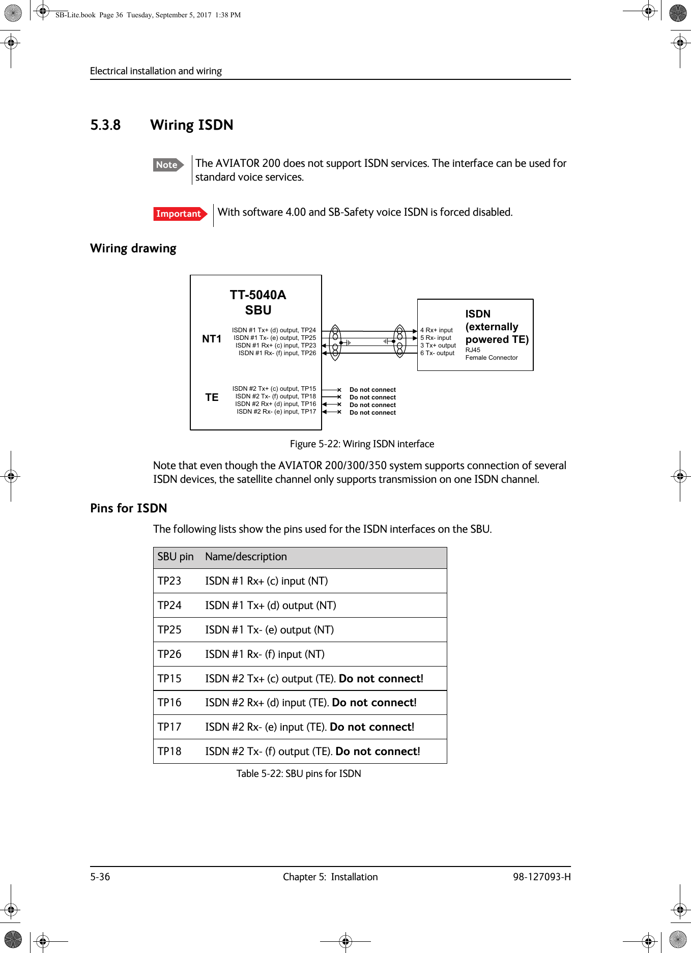
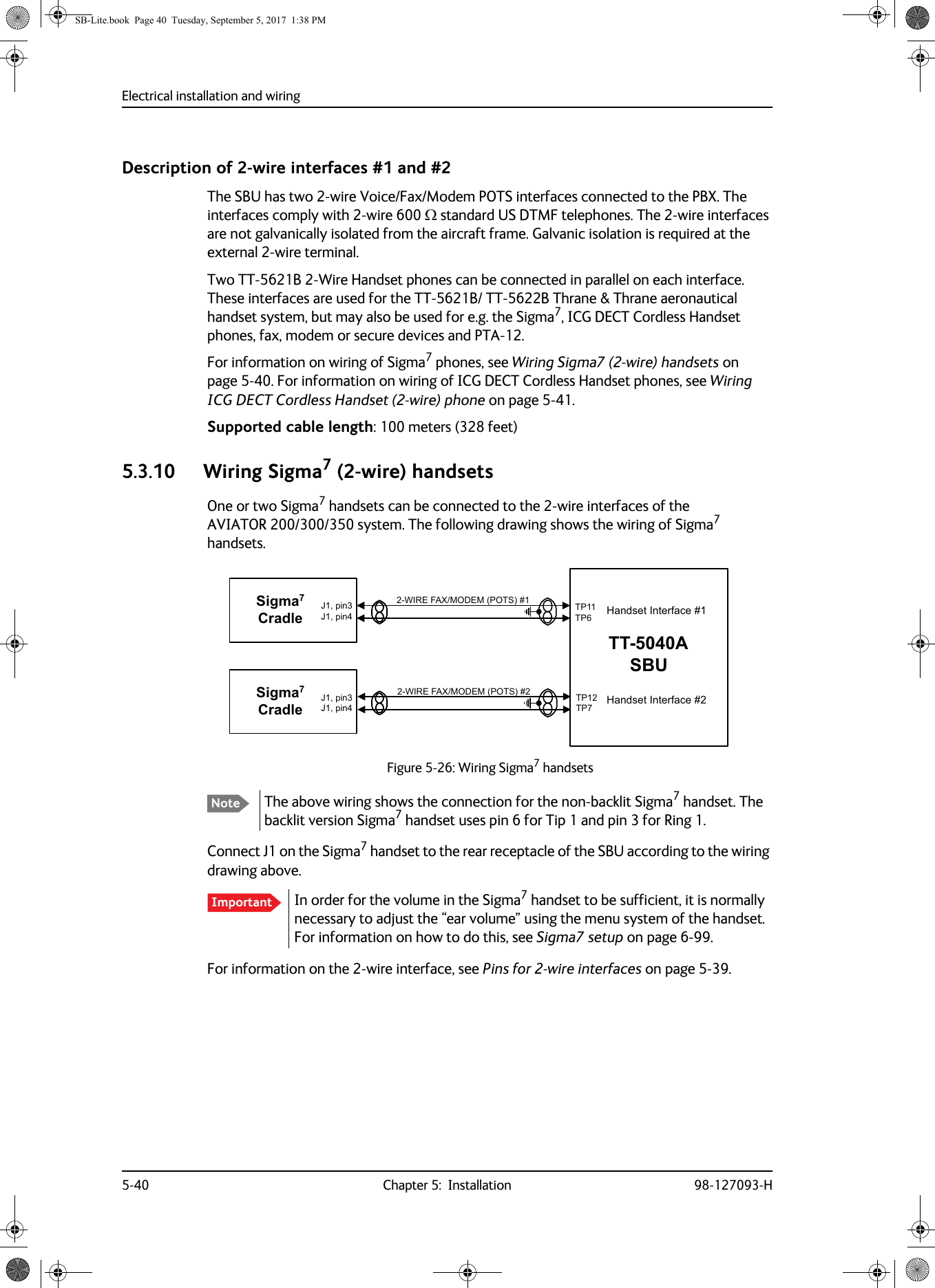
![Electrical installation and wiring98-127093-H Chapter 5: Installation 5-375555Description of SBU ISDN interfaceThe SBU has one ISDN interface. The ISDN of the SBU uses the SwiftBroadband service. The Euro ISDN S-bus interface is configured as the network side of the NT1 interface i.e. Rx is an input and Tx is an output.The ISDN interface on the SBU can address up to 8 ISDN devices. The ISDN interface supports 56/64kbps data rate and G4 Fax on the SwiftBroadband connection. You can also use the SBU ISDN interface to make an AMBE2 or 3.1 kHz audio call. The SBU does not provide DC power on the ISDN interface of the SBU. All ISDN devices connected to the SBU must be powered externally.To be compliant with ISO8877 [2] and the ISDN connector specification defined by ITU I.420 [6], an RJ45 Female Connector must be connected to the four-wire ISDN lines from the SBU. The SBU includes an internal 100 termination resistor to support cable lengths up to 100 meters (109 yards). Make sure the other end of the cable is terminated properly.Cable requirements for ISDN• Cable for the ISDN interface: 100 4-wire shielded cable.• The conductors must be twisted in pairs.• Supported cable lengths: up to 100 meters (328 feet).5.3.9 Wiring telephone systemsBuilt-in Private Branch Exchange (PBX) The built-in PBX of the SBU controls the 2-wire POTS interfaces #1 and #2 and one ISDN interface.The built-in PBX can also route VoIP calls that are terminated in the SIP server of the SBU.Without the Multi-voice option the AVIATOR 200/300/350 system supports one external call at a time. When the circuit-switched connection is in use by another phone, you have to wait until the line if free.VoIP calls and SIP telephonyYou can use phones with a SIP client and the WLAN interface to make calls. These calls are terminated in the SIP server of the SBU and routed through the built-in PBX on the Swift Broadband channel. For a detailed description how to set up your phone see SIP setup for ImportantFigure 5-23: ISDN RJ45 connector,6'15[,QSXWF,6'17[2XWSXWG,6'17[2XWSXWH,6'15[,QSXWIQRWFRQQHFWHG5-IHPDOHFRQQHFWRUQRWFRQQHFWHGQRWFRQQHFWHGQRWFRQQHFWHG5-IHPDOHSB-Lite.book Page 37 Tuesday, September 5, 2017 1:38 PM](https://usermanual.wiki/Thrane-and-Thrane-A-S/AVIATOR.Installations-Manual/User-Guide-4022359-Page-109.png)
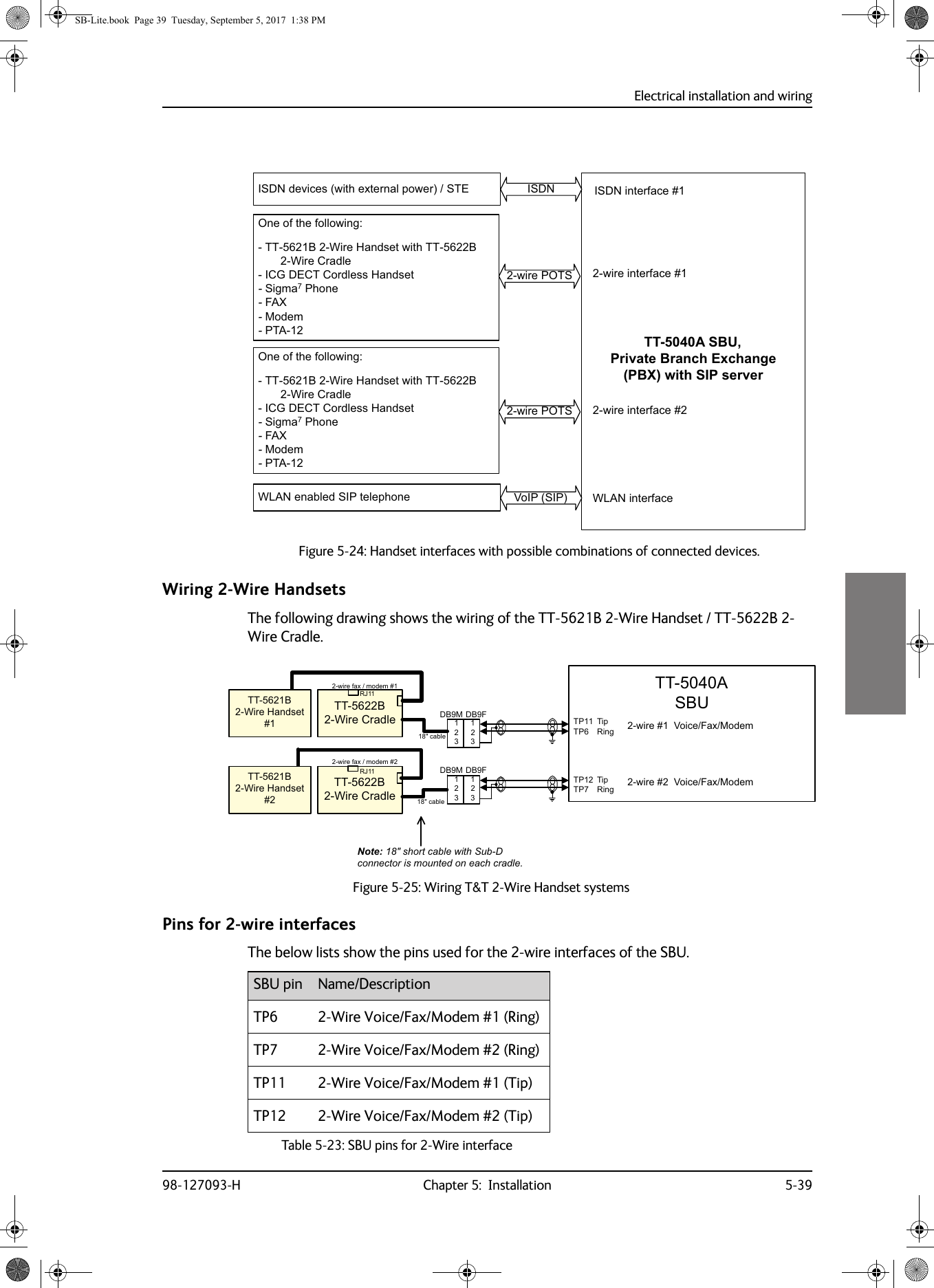
![Electrical installation and wiring98-127093-H Chapter 5: Installation 5-4155555.3.11 Wiring ICG DECT Cordless Handset (2-wire) phoneOne or two ICG DECT Cordless Handset phones can be connected to the 2-wire interfaces of the AVIATOR 200/300/350 system. The following drawing shows the wiring of ICG DECT Cordless Handset 2-wire phones.Connect J2 on the base station of the ICG DECT Cordless Handset phone to the rear receptacle of the SBU according to the wiring drawing above. The base station is supplied together with the handset and cradle.In order for the ICG DECT Cordless Handset phone to work properly, it is normally necessary to make a few initial adjustments of the handset. For information on how to do this, see ICG DECT Cordless Handset setup on page 6-99.For information on the 2-wire interface, see Pins for 2-wire interfaces on page 5-39.Figure 5-27: Wiring ICG DECT Cordless Handset handsetsImportant:,5()$;02'(03276*+]&RUGOHVV%DVH8QLW:,5()$;02'(0327677$6%873737373-SLQ-SLQ-SLQ*+]&RUGOHVV%DVH8QLW-SLQ-SLQ-SLQ+DQGVHW,QWHUIDFH+DQGVHW,QWHUIDFHSB-Lite.book Page 41 Tuesday, September 5, 2017 1:38 PM](https://usermanual.wiki/Thrane-and-Thrane-A-S/AVIATOR.Installations-Manual/User-Guide-4022359-Page-113.png)

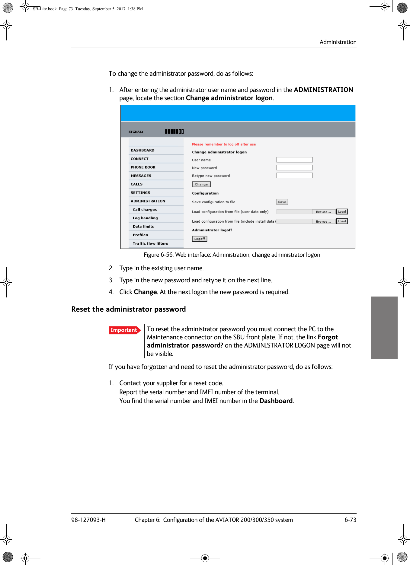
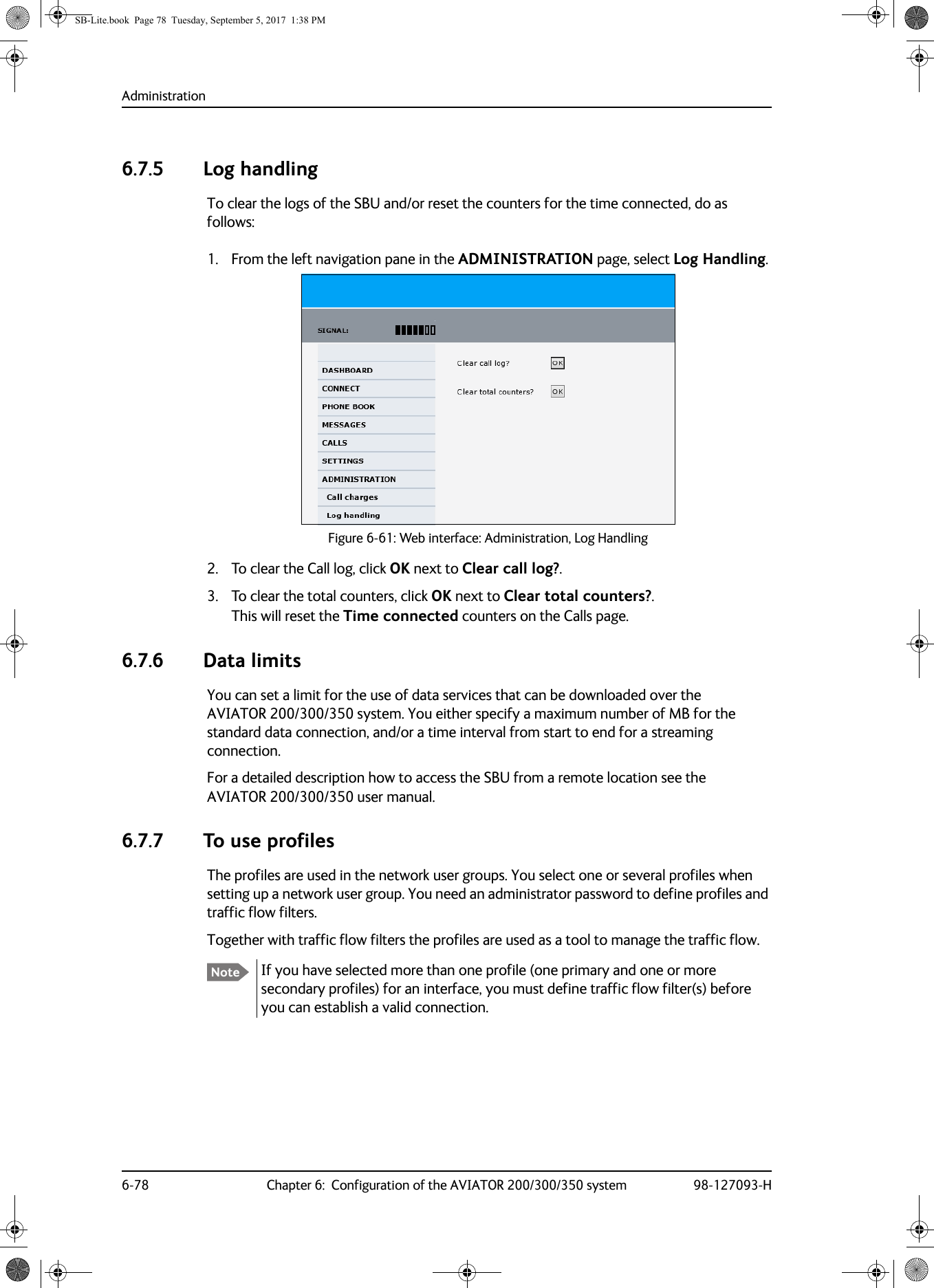
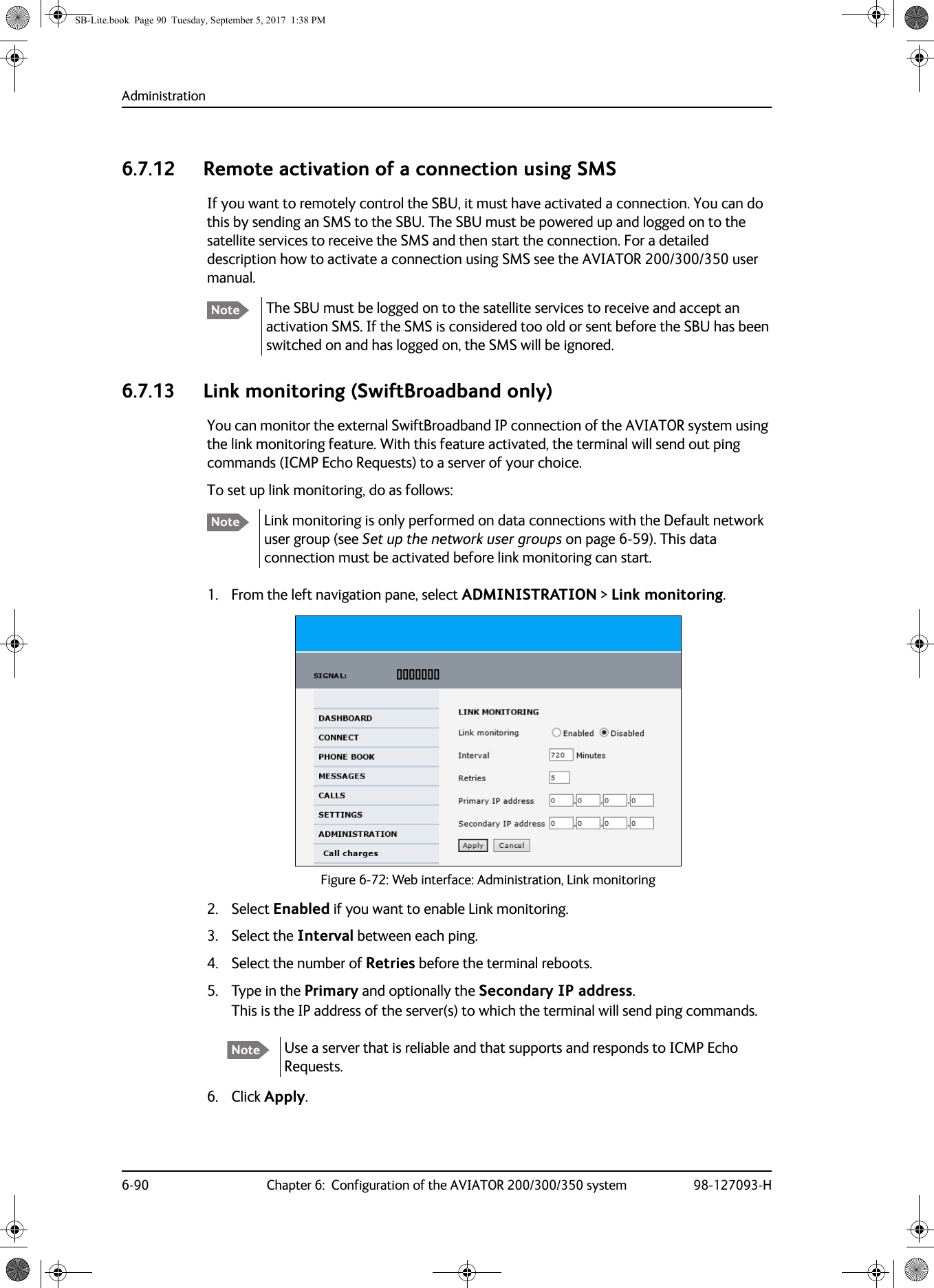
![Administration6-72 Chapter 6: Configuration of the AVIATOR 200/300/350 system 98-127093-H6.7.2 Access the administration settingsLog on as administratorThe Administration settings require an Administration user name and password. You must also login as an administrator in the sections for SETTINGS, LAN, Network Devices, Network classification, Network user groups and PPPoE.To log on as administrator, do as follows:1. Select ADMINISTRATION from the left navigation pane.2. Enter the Administration user name and password.The default user name is admin and the default password is 1234. If you have forgotten the administrator password, you can reset the password by clicking the link at the bottom of the page.1 For further information, see the next section Reset the administrator password.3. Click Logon.The Administration page is now updated to let you change the user name and password, Save/load a configuration or log off Administration.Change the administrator passwordIf you have a Level D system with the Built-in CMU/ACARS option and the ACARS service is enabled, the admin password must fulfill the following requirements:• have at least 8 characters• must contain letters, figures and special characters (<>,;.:-_/*-+!.#¤%&()=?@£${[]}|)The default password 1234 is allowed, but it will trigger a warning that is displayed after each reboot of the system.Figure 6-55: Web interface: Administration1. The link is only shown when the PC is connected to the Maintenance connector on the SBU front plate.SB-Lite.book Page 72 Tuesday, September 5, 2017 1:38 PM](https://usermanual.wiki/Thrane-and-Thrane-A-S/AVIATOR.Installations-Manual/User-Guide-4022359-Page-196.png)
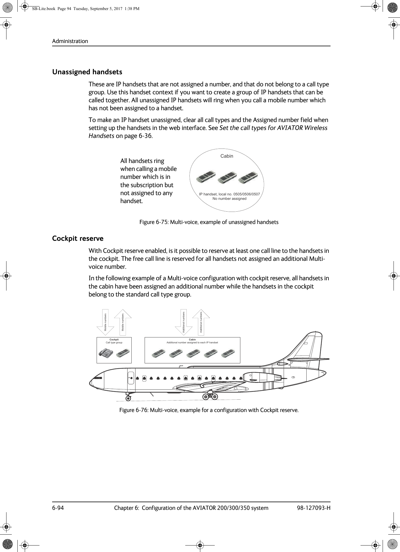
![Administration98-127093-H Chapter 6: Configuration of the AVIATOR 200/300/350 system 6-936666Directly assigned handsetsThe mobile numbers are assigned to individual handsets. Only the assigned handset will ring when the associated number is called.For information on how to assign a number to a handset, see the pages SETTINGS > Phone/Fax, SETTINGS > ISDN or SETTINGS > IP handsets in the web interface.Note that you can also assign the call type numbers directly (in the example above, the Standard Voice number is assigned to IP handset number 0501). If you do so, be aware that only the assigned handset can receive a call to this number. The handset connected to the Phone port 1 and the IP handset no. 0502 are each assigned an additional number.Figure 6-73: Multi-voice, call type groups (example)&DOO7\SH 6WDQGDUG &DOO7\SH N+]6WDQGDUG9RLFHQXPEHU,6'13RUW3KRQH)D[3RUW,6'13RUW3KRQH)D[3RUWN+]$XGLRQXPEHU[Note To use this feature you must have additional numbers in your airtime subscription and enable the use of additional numbers in the web interface. Then you can assign the numbers to individual handsets. For details on additional numbers, see Additional numbers for Multi-voice on page 6-92.Figure 6-74: Multi-voice, example of directly assigned handsets (example),3KDQGVHWORFDOQR $GGLWLRQDOQXPEHU&DELQ,3KDQGVHWORFDOQR 6WDQGDUG9RLFHQXPEHU3DQWU\3KRQH)D[SRUW $GGLWLRQDOQXPEHU&RFNSLWSB-Lite.book Page 93 Tuesday, September 5, 2017 1:38 PM](https://usermanual.wiki/Thrane-and-Thrane-A-S/AVIATOR.Installations-Manual/User-Guide-4022359-Page-217.png)

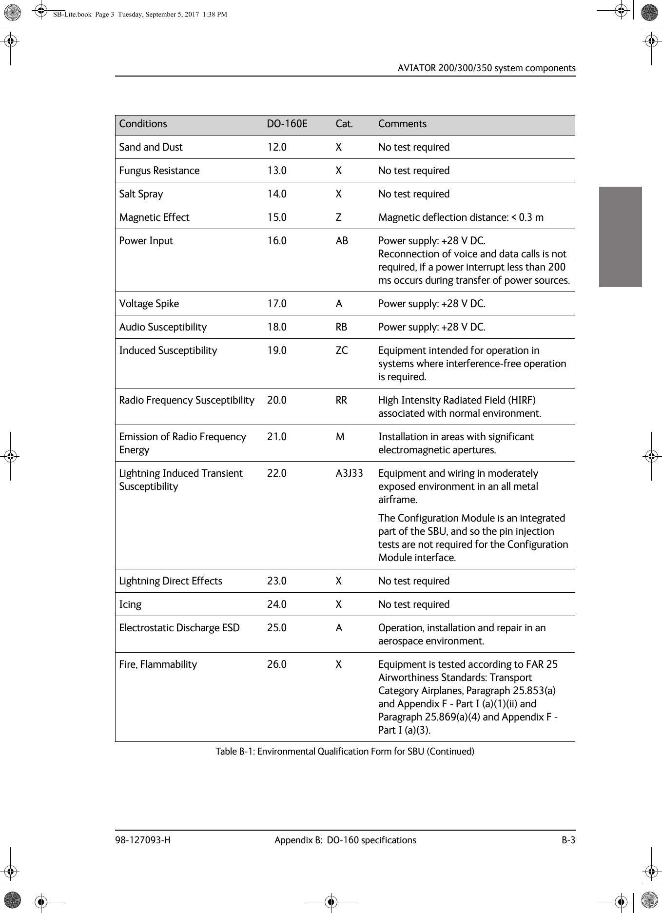
![AVIATOR 200/300/350 system componentsB-2 Appendix B: DO-160 specifications 98-127093-HB.2 AVIATOR 200/300/350 system componentsB.2.1 SwiftBroadband unit (SBU)Part Number: 405040A (AVIATOR 200/300/350) or 405040A-THD (AVIATOR 200D/300D/350D)DO-160E string: [(A1)(F1)X]CAB[SB2M]ExxxxxZ[AB]A[RB][ZC][RR]M[A3J33]XXAXConditions DO-160E Cat. CommentsTemperature and Altitude 4.0 A1, F1 Installation in temperature controlled areas and inside or outside pressurized locations.Low Temperature 4.5.1 & 4.5.2 Short time operating low is -40°C. Unit is active, but inoperable until the unit temperature is > -30°C.Min. operational temperature is -25°C.High Temperature 4.5.3 & 4.5.4 Short time operating high (30 min.): +70°CMax. operating high temperature is +55°CIn-Flight Loss of Cooling 4.5.5 X Forced cooling is not required and not recommended.Altitude 4.6.1 Max. altitude: 55000 ftDecompression 4.6.2 Decompression test at 55000 ftOverpressure 4.6.3 Overpressure at -15000 ftTemperature Variation 5.0 C Installation within temperature controlled areas: 2°C/min.Humidity 6.0 A Standard Humidity: 95% relative humidity at 38°C to 50°C for 48 hours. Installation within environmentally controlled zonesOperational Shocks and Crash Safety7.0 B Equipment tested to: Standard operational shock and crash safety.Vibration 8.0 S, B2, MEquipment tested without shock mounts to Category S, Curve B2 and Curve M.Explosion Proofness 9.0 E Not hermetically sealed equipmentWaterproofness 10.0 X No test requiredFluids Susceptibility 11.0 X No test requiredTable B-1: Environmental Qualification Form for SBU SB-Lite.book Page 2 Tuesday, September 5, 2017 1:38 PM](https://usermanual.wiki/Thrane-and-Thrane-A-S/AVIATOR.Installations-Manual/User-Guide-4022359-Page-256.png)
![AVIATOR 200/300/350 system componentsB-4 Appendix B: DO-160 specifications 98-127093-HB.2.2 Configuration Module (CM) for SBUPart Number: 405040A-001DO-160E string: Please refer to the section SwiftBroadband unit (SBU) on page B-2, as the Configuration Module is an integral part of the SBU during normal operation and tests. However, the section 25 Category A test is performed on the Configuration Module as an individual LRU.B.2.3 High Power Amplifier/Low Noise Amplifier/Diplexer (HLD)Part Number: 405016A (AVIATOR 200/300/350) + 405016A-THD (AVIATOR 200D/300D/350D)DO-160E string: [(A2)(F2)X]BBB[SCL]E[(Y)(W)]XXFXZXXX[ZC][RR]M[A3J33]XXAXConditions DO-160E Cat. CommentsTemperature and Altitude 4.0 A2, F2 Installation in non-temperature controlled locations and inside or outside pressurized locations.Low Temperature 4.5.1 & 4.5.2 Min. operational temperature is -55°C. Short time operating low is -55°C.High Temperature 4.5.3 & 4.5.4 Max. operating high temperature: +70°C Short time operating high: +70°CIn-Flight Loss of Cooling 4.5.5 X Forced cooling is not required and not recommended.Altitude 4.6.1 Max. altitude: 55000 ft.Decompression 4.6.2 Decompression at 55000 ft.Overpressure 4.6.3 Overpressure at -15000ft.Temperature Variation 5.0 B Installation in a non-temperature-controlled or partially temperature controlled internal section of the aircraft.Humidity 6.0 B Severe Humidity: 95% relative humidity at 38°C to 65°C for 240 hours. Installation within environmentally controlled zones.Operational Shocks and Crash Safety7.0 B Equipment tested to: Standard operational shocks and crash safety.Vibration 8.0 SCL Fixed wing turbojet & turboprop/fuselage zone: Category S, Curve C & L.Table B-2: Environmental Qualification Form for HLD SB-Lite.book Page 4 Tuesday, September 5, 2017 1:38 PM](https://usermanual.wiki/Thrane-and-Thrane-A-S/AVIATOR.Installations-Manual/User-Guide-4022359-Page-258.png)
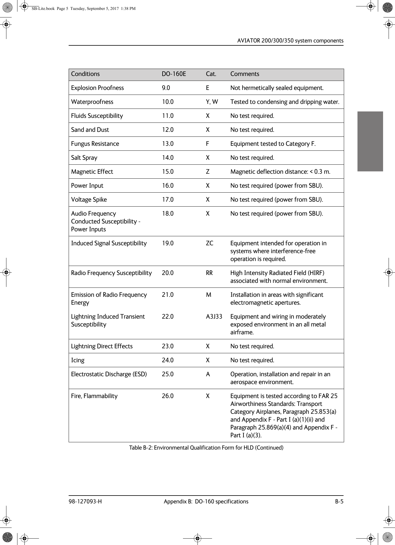
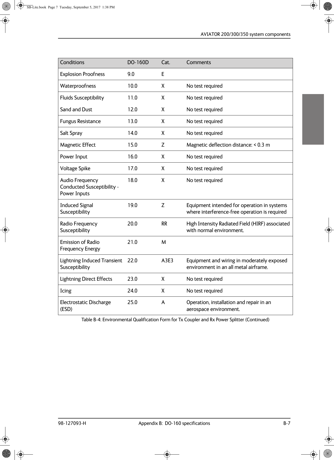
![AVIATOR 200/300/350 system componentsB-6 Appendix B: DO-160 specifications 98-127093-HB.2.4 Rx Power SplitterPart Number: 405038A-003DO-160D string: [(A1)(F1)X]CBB[SCL]EXXXXXZXXXZ[RR]M[A3E3]XXARTCA/DO-160D Change NumbersChange Number Date of Issue Title SectionChange No. 1 Dec. 14, 2000 VibrationRadio Frequency Susceptibility8.020.0Change No. 2 June 12, 2001 Power InputAudio Frequency Conducted Susceptibility - Power Inputs16.018.0Table B-3: RTCA/DO-160D Change Numbers, Tx Coupler and Rx Power SplitterConditions DO-160D Cat. CommentsTemperature and Altitude 4.0 A1 and F1Installation in controlled temperature locations and inside or outside pressurized locations.Low Temperature 4.5.1 Min. operating low temperature: -25°CHigh Temperature 4.5.2 & 4.5.3 Max. operating high temperature: +55°CIn-Flight Loss of Cooling 4.5.4 X Forced cooling is not recommended.Altitude 4.6.1 Max. altitude: 55000 ftDecompression 4.6.2 Decompression at 55000 ftOverpressure 4.6.3 Overpressure at -15000 ftTemperature Variation 5.0 C Installation within controlled temperature locations: 2°/min.Humidity 6.0 B Severe humidity: 95% relative humidity at 38°C to 65°C for 240 hours. Installation within non-environmentally controlled zones.Operational Shocks and Crash Safety7.0 B Equipment tested to: Standard operational shocks and crash safety.Vibration 8.0 SCL Standard sinusoidal and random vibration: Aircraft type: Fixed wing. Turbojet, turbofan, reciprocating or turbo propeller engines.Aircraft zone: FuselageTable B-4: Environmental Qualification Form for Tx Coupler and Rx Power Splitter SB-Lite.book Page 6 Tuesday, September 5, 2017 1:38 PM](https://usermanual.wiki/Thrane-and-Thrane-A-S/AVIATOR.Installations-Manual/User-Guide-4022359-Page-260.png)
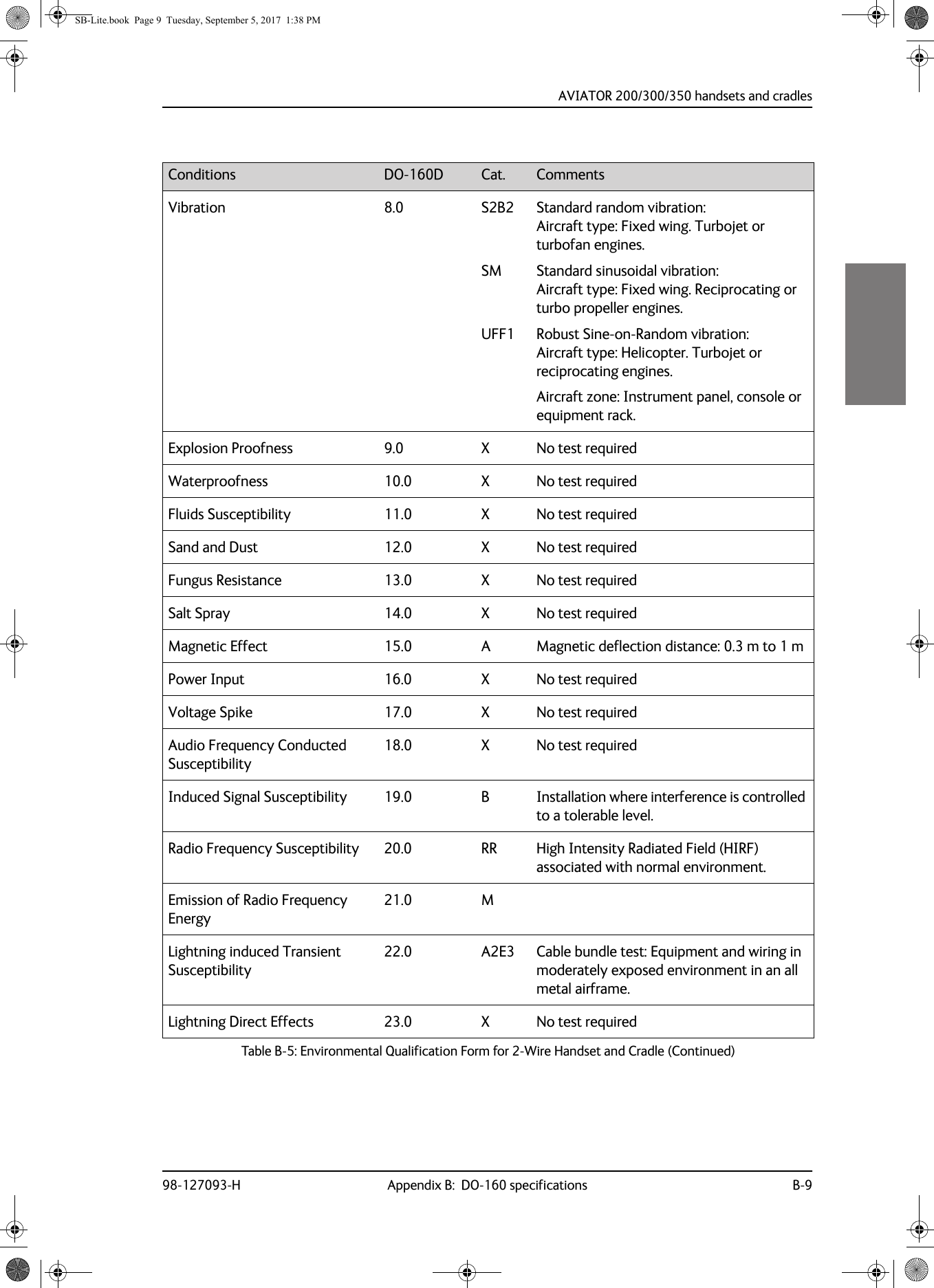
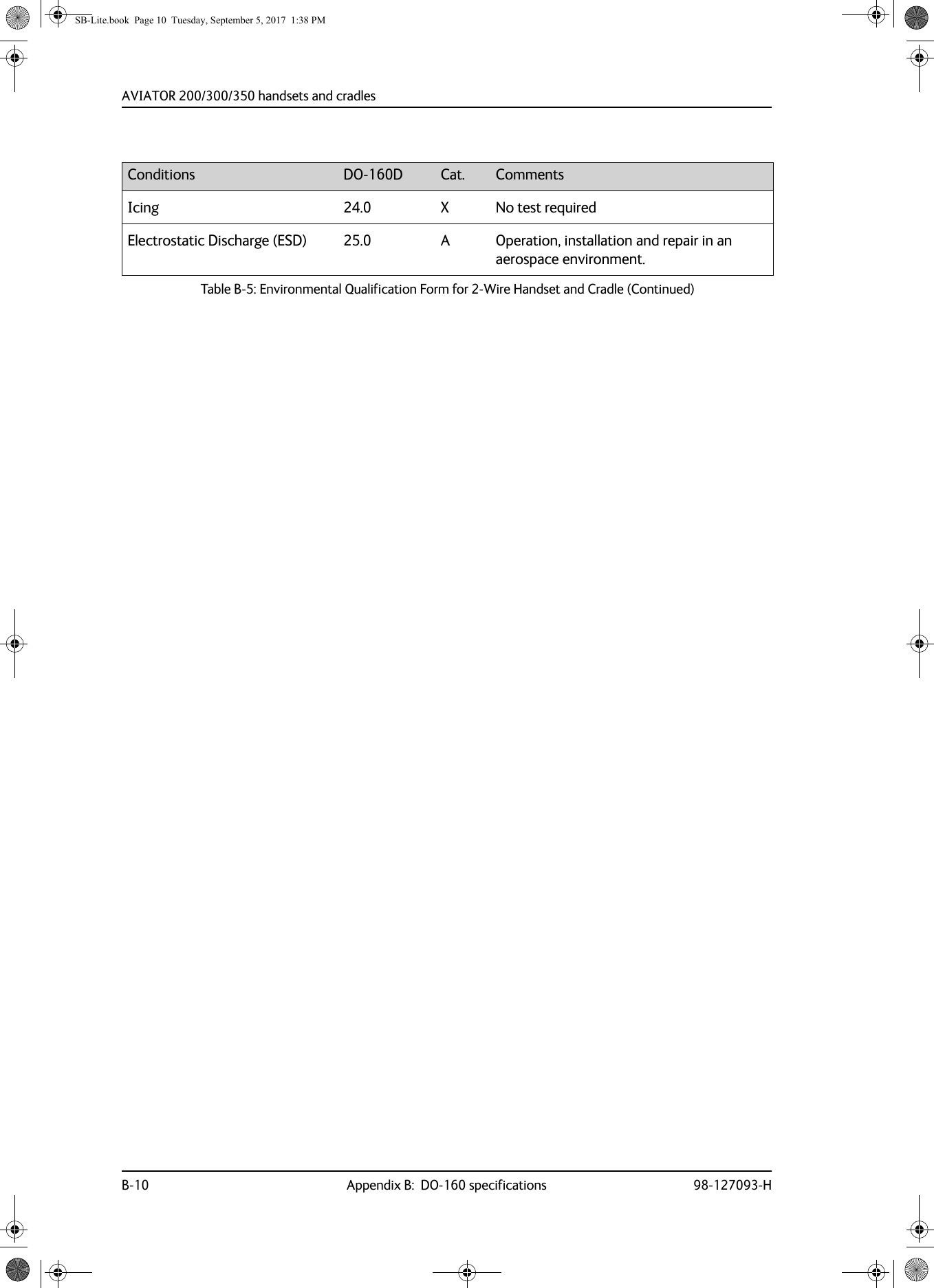
![AVIATOR 200/300/350 handsets and cradlesB-8 Appendix B: DO-160 specifications 98-127093-HB.3 AVIATOR 200/300/350 handsets and cradlesB.3.1 2-Wire Handset and 2-Wire CradlePart Number: 405621B-THW / 405621B-THR / 405622B-THW / 405622B-THRDO-160C String: [A1X]CAB[(SMB2)(SM)(UFF1)]XXXXXXAXXXB[RR]M[A2E3]XXANote For DO-160 specifications of the AVIATOR Wireless Handset see AVIATOR Wireless Handset and Cradle Installation & Maintenance Manual (part number: 98-129600)Conditions DO-160D Cat. CommentsTemperature and Altitude 4.0 A1 Installation in controlled temperature and pressurized location.Low Temperature 4.5.1 Min. operating low temperature: -25°CHigh Temperature 4.5.2 & 4.5.3 Max. operating high temperature: +55°CIn-Flight Loss of Cooling 4.5.4 X No forced cooling required.Altitude 4.6.1 Max. altitude: 55000 ftDecompression 4.6.2 Decompression at 55000 ftOverpressure 4.6.3 Overpressure test at -15000 ftTemperature Variation 5.0 C Installation within controlled temperature locations: 2°/min.Humidity 6.0 A Standard Humidity: 95% relative humidity at 38°C to 50°C for 48 hours. Installation within environmentally controlled zones.Operational Shocks and Crash Safety7.0 B Equipment tested to: Standard operational shocks and crash safety.Table B-5: Environmental Qualification Form for 2-Wire Handset and Cradle SB-Lite.book Page 8 Tuesday, September 5, 2017 1:38 PM](https://usermanual.wiki/Thrane-and-Thrane-A-S/AVIATOR.Installations-Manual/User-Guide-4022359-Page-262.png)
![98-127093-H E-1Appendix EEEEEReferences EE.1 Applicable standards[1] IEEE Standard for Information technology - Telecommunications and information exchange between systems - Local and metropolitan area networks - Specific requirements Part 3: Carrier sense multiple access with collision detection (CSMA/CD) access method and physical layer specifications. IEEE Std 802.3, 2000 Edition (Incorporating IEEE Std 802.3, 1998 Edition, IEEE Std 802.3ac-1998, IEEE Std 802.3ab-1999, and IEEE Std 802.3ad-2000) [Adopted by ISO/IEC and re-designated as ISO/IEC 8802-3:2000(E)].[2] ISO/IEC 8877:1992 Information technology -- Telecommunications and information exchange between systems -- Interface connector and contact assignments for ISDN Basic Access Interface located at reference points S and T[3] RTCA/DO-160D. Environmental Conditions and Test Procedures for Airborne Equipment. RTCA Inc. July 29, 1997[4] RTCA/DO-160E. Environmental Conditions and Test Procedures for Airborne Equipment. RTCA Inc. December 9, 2004[5] Integrated Services Digital Network (ISDN). Basic User-Network Interface (UNI). ETSI EN 300 012-1 V1.2.2 (ITU I.430))[6] Integrated Services Digital Network (ISDN). ISDN User Network Interfaces. ITU-T Recommendation I.420[7] ARINC 429. Mark 33 Digital Information Transfer Systems (DITS)[8] ARINC 404A. Air Transport Equipment Cases and Racking[9] CCITT Rec. G.473. Standard US DTMF Telephone[10] RTCA/DO-178B. Software Considerations in Airborne Systems and Equipment Certification, December 1, 1992[11] RTCA/DO-254. Design Assurance Guidance for Airborne Electronic Hardware, April 19, 2000[12] ARINC CHARACTERISTIC 704A. Inertial Reference System[13] ARINC CHARACTERISTIC 705. Attitude and Heading Reference System[14] ARINC CHARACTERISTIC 743A. GNSS SensorSB-Lite.book Page 1 Tuesday, September 5, 2017 1:38 PM](https://usermanual.wiki/Thrane-and-Thrane-A-S/AVIATOR.Installations-Manual/User-Guide-4022359-Page-279.png)
![Applicable standardsE-2 Appendix E: References 98-127093-H[15] ARINC CHARACTERISTIC 741P1. Aviation Satellite Communication System Part 1. Aircraft installation provisions[16] ARINC CHARACTERISTIC 781. Mark 3 Aviation Satellite Communication SystemsSB-Lite.book Page 2 Tuesday, September 5, 2017 1:38 PM](https://usermanual.wiki/Thrane-and-Thrane-A-S/AVIATOR.Installations-Manual/User-Guide-4022359-Page-280.png)
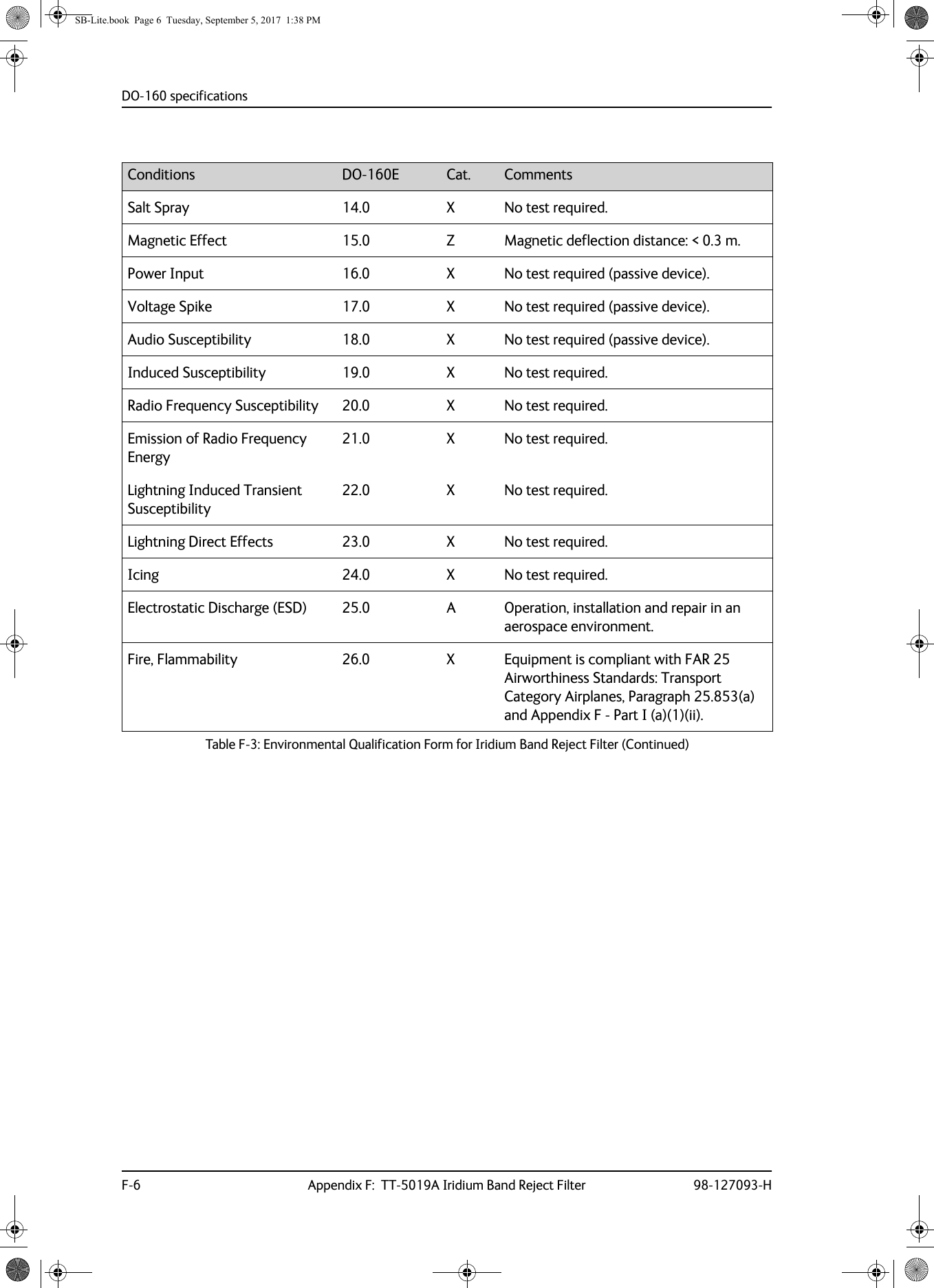
![DO-160 specifications98-127093-H Appendix F: TT-5019A Iridium Band Reject Filter F-5FFFFF.6 DO-160 specificationsT&T Part Number: 405019ADO-160E string: [(A1)(F1)X]BAB[SCLM]EXXXXXZXXXXXXXXXAXConditions DO-160E Cat. CommentsTemperature and Altitude 4.0 A1, F1 Installation in temperature controlled areas and inside or outside pressurized locations.Low Temperature 4.5.1 & 4.5.2 Short time operating low temp.: -40°C. Min. operational temperature: -25°C.High Temperature In-Flight Loss of Cooling 4.5.3 & 4.5.4 Short time operating high temperature: +70°C. Max. operational high temp.: +55°C.In-Flight Loss of Cooling 4.5.5 X Forced cooling is not required and not recommended.Altitude 4.6.1 Max. altitude: 55000 ft.Decompression 4.6.2 Decompression at 55000 ft.Overpressure 4.6.3 Overpressure at -15000ft.Temperature Variation 5.0 B Installation within non-controlled temperature locations: 5°/min.Humidity 6.0 A Standard Humidity: 95% relative humidity at 38°C to 50°C for 48 hours. Installation within environmentally controlled zones.Operational Shocks and Crash Safety7.0 B Equipment tested to: Standard operational shocks and crash safety.Vibration 8.0 SCLM Fixed wing turbojet & turboprop/fuselage and equipment rack: Category S, Curve C, L & M.Explosion Proofness 9.0 E Not hermetically sealed equipment.Waterproofness 10.0 X No test required.Fluids Susceptibility 11.0 X No test required.Sand and Dust 12.0 X No test required.Fungus Resistance 13.0 X No test required.Table F-3: Environmental Qualification Form for Iridium Band Reject Filter SB-Lite.book Page 5 Tuesday, September 5, 2017 1:38 PM](https://usermanual.wiki/Thrane-and-Thrane-A-S/AVIATOR.Installations-Manual/User-Guide-4022359-Page-285.png)