Thrane and Thrane A S AVIATOR Satellite transceiver for Inmarsat Swift Broadband service User Manual
Thrane & Thrane A/S Satellite transceiver for Inmarsat Swift Broadband service
Contents
- 1. Installations Manual
- 2. Users Manual
Installations Manual
AVIATOR 200/300/350
Installation manual
98-127093-G Cover_Installation manual AVIATOR 200-300-350.indd 1 03-07-2013 15:19:18
98-127093-G Cover_Installation manual AVIATOR 200-300-350.indd 2 03-07-2013 15:19:18
AVIATOR 200/300/350
Document number: 98-127093-H
Release date: 5 September 2017
Installation & maintenance manual
SB-Lite.book Page i Tuesday, September 5, 2017 1:38 PM

ii 98-127093-H
Disclaimer
Information in this document is subject to change without notice.
The information, drawings and wiring diagrams contained in this manual are intended as a reference for
engineering planning only. The drawings and wiring diagrams contained herein do not represent any
specific Supplemental Type Certificate (STC). It is the installer's responsibility to compose installation
drawings specific to the aircraft. This manual and the drawings and wiring diagrams contained herein may
not be used as a substitute for an STC package.
The newest versions of Cobham SATCOM user and installation manuals as well as outline drawings can be
downloaded from www.cobham.com/satcom, Cobham SYNC Partner Portal. Some material and
features are for partners only and can only be accessed after login with a password.
Thrane & Thrane A/S is not responsible for the content or accuracy of any translations or reproductions,
in whole or in part, of this manual from any other source. In the event of any discrepancies, the English
version shall be the governing text.
Thrane & Thrane A/S is trading as Cobham SATCOM.
Copyright
© 2017 Thrane & Thrane A/S. All rights reserved. Printed in Denmark.
Trademark Acknowledgements
•Inmarsat is a registered trademark of the International Maritime Satellite Organization (IMSO) and is
licensed by IMSO to Inmarsat Limited and Inmarsat Ventures plc.
• Inmarsat’s product names are either trademarks or registered trademarks of Inmarsat.
•Windows is a registered trademark of Microsoft Corporation in the United States and other
countries.
• Other product and company names mentioned in this manual may be trademarks or trade names of
their respective owners.
Company web site
www.cobham.com/satcom
Disposal
Old electrical and electronic equipment marked with this symbol can contain substances
hazardous to human beings and the environment. Never dispose these items together with
unsorted municipal waste (household waste). In order to protect the environment and
ensure the correct recycling of old equipment as well as the re-utilization of individual
components, use either public collection or private collection by the local distributor of old electrical and
electronic equipment marked with this symbol.
Contact the local distributor for information about what type of return system to use.
SB-Lite.book Page ii Tuesday, September 5, 2017 1:38 PM

98-127093-H iii
Record of revisions
Rev. Description Release Date Initials
A Original document 12 March 2008 CC
B General update to version B. 25 September
2008
UFO
C Configuration of interfaces and network management added.
Specifications and DO-160 string of the HLD updated. Editorials.
28 November
2008
UFO
D Page iii: Disposal added
The following chapters have been added: 6.7.7
The following chapters have been edited: 2.1.1, 2.3.4, 5.1.2, 5.2.2-
5.2.4, 5.3.3, 5.3.4, 5.3.6, 5.3.7, 5.3.10, 5.4.3, 5.4.5 - 5.4.7, 6.2.2, 6.5,
6.6.1, 6.6.3 - 6.6.5, 6.6.8 - 6.6.13, 6.7.7, 6.8.7, 7.4.2, 7.5.4, 7.7
The following appendices have been added: E, F
The following tables have been added: 5-12, 6-3, 6-4
The following tables have been edited: 2-1, 2-3, 2-5, 4-3, 5-21, 5-
22, 5-28, B-1, B-2, B-3,
The following figures have been added: 2-3, 2-4, 3-7, 5-6, 5-9, 7-5
The following figures have been edited: 3-10, 3-11, 5-16, 6-2, 6-52
7 May 2009 UFO
E AVIATOR 200 added. The AVIATOR 300 and AVIATOR 350 replace
the earlier Thrane & Thrane Aero-SB Lite system.
The following chapters have been added: 5.3.5, 6.5.10, 6.5.15,
6.6.8, 6.7.5, 6.7.10, 6.7.11, 6.7.12, A.2.5, B.2.4, Appendix C,
Appendix G.
The following chapters have been edited: 2.1.1, 2.1.2, 2.2, 2.3, 4.1.3,
4.4.1, 5.2.4, 5.3.2, 5.3.4, 5.3.7, 5.3.11, 5.4.4, 5.5, 6.2.2, 6.3.4, 6.4,
6.6.1, 6.6.4, 6.5.8, 6.5.12, 6.5.12, 6.5.13, 6.5.14, 6.6.6, 6.6.7, 6.7.2,
6.10, 7.2.2, 7.2.3, 7.4 (reorganized), A.1.1 removed, E.1,
The following tables have been added: 5-7
The following tables have been edited: 2-3, 5-6, 5-28, A-1, F-1, F-2.
The following figures have been added: 3-3, 3-5, 3-10, 3-11, 3-13,
3-14, 5-4.
The following figures have been edited: 4-3, 5-1, 6-2, 6-4, 6-23, 6-
30, 6-33, 6-46, 6-48, 6-49, 6-54, 6-56, 6-58, 7-3, F-2.
The section “Using the Call log” has been moved to the user
manual.
29 July 2010 UFO
SB-Lite.book Page iii Tuesday, September 5, 2017 1:38 PM

iv 98-127093-H
F The following chapters have been added: 3.13, 6.1.1, 6.5.9, 6.6.9,
6.7.1,
The following chapters have been edited: 1.1, 2.1, 2.1.1, 2.2.2, 3.1,
3.10, 5.2.5, 5.3.7, 5.4.6, 6.3.2, 6.5.4, 6.7.2, 7.1.1, 7.3, A-3, B.2.1, B.3,
B.3.1, H.1.2.
The following tables have been edited: 1-1, 2-3, 2-7, 5-1, 5-6, 5-9,
5-29, 6-3, A-1, A-2, A-3, A-4, A-5, A-6, A-7,
The following figures have been edited: 2-1, 3-1, 3-4, 5-1, 6-9, 6-
10, 6-28, 6-30, 6-34.
16 March 2012 UFO
G The following sections have been added: 6.5.15, 6.7.14, 7.4
The following sections have been edited: 2.1.1, 2.1.2, 2.3.1, 2.3.3,
5.2.3, 5.3.4, 5.3.5, 5.3.9, 6.4.2, 6.5.5, 6.5.6, 6.5.8, 6.5.16, 6.72,
6.7.10, 7.3.1
The following tables have been edited: 2-1, 2-2, 2-3, 4-3, 5-1, 5-12,
5-13, 6-3, 7-4, A-1, C-1, F-2
The following figures have been added: 5-12, 5-5, 6-8, 6-13
The following figures have been edited: 2-2, 3-2, 5-4, 5-5, 5-6, 5-7,
5-8, 5-9, 5-10, 5-11, 5-14, 6-32, 6-34, 6-73
27 March 2014 UFO
H The following sections have been added: 2.1.1 (p. 2-4 +2-5), 5.3.14,
6.5.18, 6.7.13, 7.3
The following sections have been edited: 2.1.2, 5.3.1, 4.1.3 (p. 4-5),
5.3. (p. 5-14), 5.3.3 (p. 5-17), 5.3.7, 5.3.8, 5.3.9, 6.5.4, 6.5.5, 6.5.6,
6.5.9, 6.5.11, 6.5.10, 6.5.14 (p. 6-47), 6.5.15, 6.5.16, 6.7, 6.7.15,
7.2.2, 7.6, F.3.1, H.1.2
The following tables have been added: 2-3, 2-4, 2-6, F-1
The following tables have been edited: 2-5, 2-9, 2-11, 4-2, 4-5, 5-1,
5-19, 5-32, 7-4, A-1, C-1
The following figures have been added: 5-10, 6-31
The following figures have been edited: 3-2, 3-12, 3-14, 3-15,6-37,
6-79
5 September
2017
UFO
SB-Lite.book Page iv Tuesday, September 5, 2017 1:38 PM

98-127093-H v
Table of contents
Chapter 1 About this manual
1.1 Purpose .....................................................................................................................................1-1
1.2 Organization .........................................................................................................................1-1
1.3 Related documentation ...............................................................................................1-2
1.4 Precautions: Warnings, Cautions and Notes ................................................1-2
Chapter 2 Introduction to the AVIATOR 200/300/350
2.1 General description .........................................................................................................2-1
2.1.1 The AVIATOR 200/300/350 system ..........................................................................2-1
2.1.2 AVIATOR 200/300/350 features .................................................................................2-7
2.2 Application ............................................................................................................................2-9
2.2.1 Minimum system .................................................................................................................2-9
2.2.2 Part numbers .........................................................................................................................2-9
2.2.3 Applicable external units ..............................................................................................2-12
2.3 System block diagrams .............................................................................................2-14
2.3.1 AVIATOR 200 system with LGA-3000 antenna ................................................2-14
2.3.2 AVIATOR 300 system with TT-5006A IGA antenna ......................................2-15
2.3.3 AVIATOR 350 system with Cobham antennas ..................................................2-16
2.3.4 AVIATOR 350 system with ARINC-741/781 antennas .................................2-17
2.3.5 AVIATOR 350D system with ACARS option and ARINC-741/781 ant. .2-18
2.3.6 User interfaces ...................................................................................................................2-19
Chapter 3 Equipment drawings
3.1 Introduction .........................................................................................................................3-1
3.2 TT-5040A SBU .....................................................................................................................3-2
3.2.1 TT-5040A-001 CM (inserted in the SBU) ...............................................................3-3
3.3 TT-5038A-003 Rx Power Splitter .........................................................................3-4
3.4 TT-5016A HLD .....................................................................................................................3-5
3.5 TT-3002A LGA .....................................................................................................................3-6
3.6 TT-5006A IGA .....................................................................................................................3-7
3.7 TT-5621B 2-Wire Handset .........................................................................................3-8
3.8 TT-5622B 2-Wire Cradle ..............................................................................................3-9
3.9 SBU trays ..............................................................................................................................3-10
3.10 SBU tray connector .....................................................................................................3-13
3.11 Contact Assembly: Quadrax Pin size 5 special .......................................3-14
SB-Lite.book Page v Tuesday, September 5, 2017 1:38 PM

Table of contents
vi 98-127093-H
3.12 TT-5040A-004 WLAN antenna ............................................................................3-16
3.13 Switch Annunciator Panel ......................................................................................3-17
Chapter 4 Connectors and pin-out
4.1 TT-5040A SBU .....................................................................................................................4-1
4.1.1 Connectors on SBU ............................................................................................................4-1
4.1.2 SBU Maintenance connector ........................................................................................4-1
4.1.3 SBU rear receptacle ............................................................................................................4-3
4.2 TT-5016A HLD .....................................................................................................................4-9
4.2.1 Connectors on HLD ............................................................................................................4-9
4.3 TT-5622B 2-Wire Cradle ...........................................................................................4-10
4.3.1 Connectors on 2-Wire Cradle ....................................................................................4-10
4.3.2 2-Wire Cradle connector to SBU ..............................................................................4-11
4.4 Mating connectors in aircraft ..............................................................................4-12
4.4.1 Connection with SBU .....................................................................................................4-12
Chapter 5 Installation
5.1 General installation information ..........................................................................5-1
5.1.1 Overview ..................................................................................................................................5-1
5.1.2 Minimum system components .....................................................................................5-2
5.2 Mounting considerations ...........................................................................................5-3
5.2.1 Overview ..................................................................................................................................5-3
5.2.2 TT-5040A SBU .....................................................................................................................5-3
5.2.3 TT-5016A HLD .....................................................................................................................5-3
5.2.4 Satcom antenna ...................................................................................................................5-4
5.2.5 TT-5040A-004 WLAN antennas ..................................................................................5-7
SB-Lite.book Page vi Tuesday, September 5, 2017 1:38 PM

Table of contents
98-127093-H vii
5.3 Electrical installation and wiring ..........................................................................5-8
5.3.1 Wiring symbols .....................................................................................................................5-8
5.3.2 Wiring power supply ..........................................................................................................5-9
5.3.3 Wiring the satcom antenna .........................................................................................5-10
5.3.4 Wiring ARINC 429 interfaces .....................................................................................5-25
5.3.5 Wiring GPS interface .......................................................................................................5-29
5.3.6 Wiring Ethernet .................................................................................................................5-31
5.3.7 Wiring WLAN antenna interface ...............................................................................5-34
5.3.8 Wiring ISDN ........................................................................................................................5-36
5.3.9 Wiring telephone systems ...........................................................................................5-37
5.3.10 Wiring Sigma7 (2-wire) handsets ..............................................................................5-40
5.3.11 Wiring ICG DECT Cordless Handset (2-wire) phone .......................................5-41
5.3.12 Wiring discretes ................................................................................................................5-42
5.3.13 Wiring the Switch Annunciator Panel ....................................................................5-44
5.3.14 Wiring an SB-Safety Voice Annunciator Panel ..................................................5-45
5.3.15 Wiring the maintenance interface ...........................................................................5-45
5.4 Recommended cables ................................................................................................5-47
5.4.1 Introduction .......................................................................................................................5-47
5.4.2 Power cables, allowed cable lengths .......................................................................5-47
5.4.3 Recommended Power cables .....................................................................................5-48
5.4.4 Recommended RF cables .............................................................................................5-48
5.4.5 Recommended cables for ARINC 429 ...................................................................5-49
5.4.6 Recommended cables for Ethernet .........................................................................5-49
5.4.7 Cables for Discrete Signals ...........................................................................................5-50
5.5 Activation of airtime services ..............................................................................5-50
Chapter 6 Configuration of the AVIATOR 200/300/350 system
6.1 Configuration tasks ........................................................................................................6-2
6.1.1 Basic configuration of the SBU ....................................................................................6-2
6.2 Tool for setup and use: Built-in web interface ..........................................6-6
6.2.1 Topics in the web interface ............................................................................................6-7
6.2.2 Check the connection to the web interface ..........................................................6-7
6.3 The Dashboard .................................................................................................................6-12
6.3.1 Overview ...............................................................................................................................6-12
6.3.2 Properties .............................................................................................................................6-12
6.3.3 View information on calls and data sessions ......................................................6-13
6.3.4 Profiles on the dashboard ............................................................................................6-14
6.4 The phone book ..............................................................................................................6-15
6.4.1 General usage .....................................................................................................................6-15
6.4.2 View and edit the mobile and additional numbers ..........................................6-15
SB-Lite.book Page vii Tuesday, September 5, 2017 1:38 PM

Table of contents
viii 98-127093-H
6.5 To set up the interfaces ...........................................................................................6-17
6.5.1 The SETTINGS page ........................................................................................................6-17
6.5.2 Select the preferred BGAN satellite .........................................................................6-18
6.5.3 Configure the LAN interface .......................................................................................6-19
6.5.4 WLAN interface (option) ..............................................................................................6-22
6.5.5 Configure the Phone/Fax interface (2-Wire) ......................................................6-24
6.5.6 Configure the ISDN interface .....................................................................................6-25
6.5.7 Set the common interface settings .........................................................................6-27
6.5.8 Set up call services ...........................................................................................................6-28
6.5.9 Manage AVIATOR Wireless Handsets ....................................................................6-34
6.5.10 Configure the discrete I/O interfaces .....................................................................6-37
6.5.11 Set the system type ........................................................................................................6-39
6.5.12 Configure RF settings .....................................................................................................6-43
6.5.13 Set up the navigational input .....................................................................................6-44
6.5.14 Calibrate the NRS magnetometer in the TT-5006A IGA ..............................6-46
6.5.15 Set up CMU/ACARS (option) ......................................................................................6-51
6.5.16 Enable system options with FLEX keys ..................................................................6-53
6.5.17 Tracking ................................................................................................................................6-54
6.5.18 SB-Safety Voice (option) ..............................................................................................6-55
6.6 LAN/WLAN network users .......................................................................................6-57
6.6.1 Introduction .......................................................................................................................6-57
6.6.2 Set up the network user groups ................................................................................6-59
6.6.3 Manage network devices ..............................................................................................6-62
6.6.4 The network classification table ...............................................................................6-63
6.6.5 Definitions for network terms ....................................................................................6-65
6.6.6 NAT (Network Address Translation) ......................................................................6-66
6.6.7 Start and stop any data session ................................................................................6-66
6.6.8 Establish a PPPoE connection ....................................................................................6-67
6.6.9 To set up static routing .................................................................................................6-70
6.6.10 SNMP interface .................................................................................................................6-71
SB-Lite.book Page viii Tuesday, September 5, 2017 1:38 PM

Table of contents
98-127093-H ix
6.7 Administration .................................................................................................................6-71
6.7.1 Protect the SBU against unintended configuration changes ......................6-71
6.7.2 Access the administration settings ..........................................................................6-72
6.7.3 Save and load a configuration ...................................................................................6-75
6.7.4 Call charges .........................................................................................................................6-77
6.7.5 Log handling .......................................................................................................................6-78
6.7.6 Data limits ............................................................................................................................6-78
6.7.7 To use profiles ...................................................................................................................6-78
6.7.8 To use traffic flow filters ..............................................................................................6-82
6.7.9 SIM card access protection: SIM PIN and SIM Lock ......................................6-85
6.7.10 Set up user permissions .................................................................................................6-87
6.7.11 Remote management .....................................................................................................6-89
6.7.12 Remote activation of a connection using SMS .................................................6-90
6.7.13 Link monitoring (SwiftBroadband only) ................................................................6-90
6.7.14 Restricted dialing ..............................................................................................................6-91
6.7.15 Multi-voice (option) ........................................................................................................6-91
6.8 Site map ................................................................................................................................6-98
6.9 Configuration of 3rd party phone systems ...............................................6-99
6.9.1 Sigma7 setup .......................................................................................................................6-99
6.9.2 ICG DECT Cordless Handset setup ..........................................................................6-99
6.10 AVIATOR 200/300/350 system ready for use ......................................6-100
Chapter 7 Maintenance and troubleshooting
7.1 Continued Airworthiness ............................................................................................7-1
7.1.1 General .....................................................................................................................................7-1
7.1.2 Instructions ............................................................................................................................7-1
7.2 Get support: HELPDESK ...............................................................................................7-3
7.2.1 Airtime support ....................................................................................................................7-3
7.2.2 System support ....................................................................................................................7-3
7.2.3 Help desk and diagnostic report ..................................................................................7-3
7.3 Software update ................................................................................................................7-5
7.3.1 SBU software update .........................................................................................................7-6
7.3.2 Verify the software update ............................................................................................7-8
7.4 To exchange LRUs ............................................................................................................7-9
7.4.1 Time consumption .............................................................................................................7-9
7.4.2 Tools ..........................................................................................................................................7-9
7.4.3 Removal and re-installation of the SBU ...................................................................7-9
SB-Lite.book Page ix Tuesday, September 5, 2017 1:38 PM

Table of contents
x 98-127093-H
7.5 Troubleshooting .............................................................................................................7-11
7.5.1 Status signalling ................................................................................................................7-11
7.5.2 Status signalling with LEDs ..........................................................................................7-12
7.5.3 IP Reset (Default) button ..............................................................................................7-14
7.5.4 View the Event list, Event log and extended status .......................................7-16
7.5.5 Self test .................................................................................................................................7-17
7.5.6 Initial troubleshooting ...................................................................................................7-18
7.6 Return units for repair ...............................................................................................7-19
7.7 Disposal of electrical and electronic equipment ..................................7-20
Appendices
Appendix A Equipment specifications
A.1 Introduction ........................................................................................................................ A-1
A.2 AVIATOR 200/300/350 system components ............................................. A-2
A.2.1 TT-5040A SwiftBroadband Unit (SBU) ................................................................... A-2
A.2.2 TT-5040A-001 Configuration Module (CM) for SBU ....................................... A-3
A.2.3 TT-5016A High Power Amp./Low Noise Amplifier/Diplexer (HLD) ............ A-4
A.2.4 TT-5040A-004 WLAN antenna ................................................................................... A-5
A.2.5 TT-5038A-003 Rx Power Splitter ............................................................................... A-5
A.3 AVIATOR 200/300/350 handsets and cradles ........................................... A-7
A.3.1 TT-5621B 2-Wire Handset ............................................................................................ A-7
A.3.2 TT-5622B 2-Wire Cradle ................................................................................................ A-7
Appendix B DO-160 specifications
B.1 General ......................................................................................................................................B-1
B.1.1 Certifying agency ................................................................................................................B-1
B.1.2 Environmental Qualification Forms ............................................................................B-1
B.2 AVIATOR 200/300/350 system components ..............................................B-2
B.2.1 SwiftBroadband unit (SBU) ............................................................................................B-2
B.2.2 Configuration Module (CM) for SBU .........................................................................B-4
B.2.3 High Power Amplifier/Low Noise Amplifier/Diplexer (HLD) ............................B-4
B.2.4 Rx Power Splitter .................................................................................................................B-6
B.3 AVIATOR 200/300/350 handsets and cradles ............................................B-8
B.3.1 2-Wire Handset and 2-Wire Cradle ............................................................................B-8
Appendix C System messages
C.1 Types of messages .......................................................................................................... C-1
C.2 List of events ...................................................................................................................... C-2
SB-Lite.book Page x Tuesday, September 5, 2017 1:38 PM

Table of contents
98-127093-H xi
Appendix D WLAN country codes
D.1 Restrictions in WLAN use ..........................................................................................D-1
D.2 Countries where the “US” country code applies .....................................D-2
Appendix E References
E.1 Applicable standards .....................................................................................................E-1
Appendix F TT-5019A Iridium Band Reject Filter
F.1 Introduction .........................................................................................................................F-1
F.1.1 System block diagram .......................................................................................................F-1
F.2 Equipment drawing .........................................................................................................F-2
F.3 Installation ............................................................................................................................F-3
F.3.1 Mounting considerations ................................................................................................F-3
F.3.2 Electrical installation and wiring ..................................................................................F-4
F.4 Configuration .......................................................................................................................F-4
F.5 Specifications ......................................................................................................................F-4
F.6 DO-160 specifications ...................................................................................................F-5
Appendix G Terminal commands
G.1 Get started ............................................................................................................................ G-1
G.1.1 Connect to the SBU .......................................................................................................... G-1
G.2 Commands for troubleshooting the SBU ...................................................... G-2
G.2.1 Monitor the ARINC interfaces on the SBU ............................................................G-2
G.2.2 Description of the status report .................................................................................. G-3
Appendix H SIP setup for Wifi-enabled phones
H.1 Introduction ........................................................................................................................H-1
H.1.1 Connect to the WLAN interface .................................................................................H-1
H.1.2 Set up a SIP profile ............................................................................................................H-1
Glossary ..............................................................................................................................................................Glossary-1
Index ................................................................................................................................................................... Index-1
SB-Lite.book Page xi Tuesday, September 5, 2017 1:38 PM

Table of contents
xii 98-127093-H
SB-Lite.book Page xii Tuesday, September 5, 2017 1:38 PM

98-127093-H xiii
List of figures
Figure 2-1: Communication devices for the AVIATOR 200/300/350 system (example for a Level E
system) 2-2
Figure 2-2: System configuration with LGA-3000 antenna...............................................................................2-14
Figure 2-3: System configuration with TT-5006A IGA antenna.....................................................................2-15
Figure 2-4: System configuration with Cobham antennas.................................................................................2-16
Figure 2-5: System configuration ARINC 429 antennas.....................................................................................2-17
Figure 2-6: System configuration ARINC 429 antennas.....................................................................................2-18
Figure 2-7: AVIATOR 200/300/350 interfaces ........................................................................................................2-19
Figure 3-1: Outline drawing: TT-5040A SBU................................................................................................................3-2
Figure 3-2: Outline drawing: TT-5040A-001 CM, inserted in the SBU............................................................3-3
Figure 3-3: Outline Drawing: Rx Power Splitter...........................................................................................................3-4
Figure 3-4: Outline drawing: TT-5016A HLD................................................................................................................3-5
Figure 3-5: Outline drawing: TT-3002A LGA................................................................................................................3-6
Figure 3-6: Outline drawing: TT-5006A IGA antenna..............................................................................................3-7
Figure 3-7: Outline drawing: TT-5621B 2-Wire Handset........................................................................................3-8
Figure 3-8: Outline drawing: TT-5622B 2-Wire Cradle............................................................................................3-9
Figure 3-9: Outline drawing: SBU tray: ECS PO299-101......................................................................................3-10
Figure 3-10: Outline drawing: SBU tray: EMTEQ MT4-2346-101 (page 1)...................................................3-11
Figure 3-11: Outline drawing: SBU tray: EMTEQ MT4-2346-101 (page 2)...................................................3-12
Figure 3-12: Outline drawing: SBU tray connector: ITT Cannon DPX2NA-67322-606..........................3-13
Figure 3-13: Contact Assembly: Quadrax Pin size 5 special: ITT Cannon 244-0011-001.....................3-14
Figure 3-14: Outline drawing: TT-5040A-004 WLAN antenna ...........................................................................3-16
Figure 3-15: Outline drawing: Switch Annunciator panel ......................................................................................3-17
Figure 4-1: SBU Maintenance connector, face view of engaging end ............................................................4-1
Figure 4-2: SBU rear receptacle, engaging end (Index code: 19).......................................................................4-3
Figure 4-3: SBU rear receptacle with pin functions ..................................................................................................4-4
Figure 4-4: TT-5016A HLD connector panel................................................................................................................4-9
Figure 4-5: 2-Wire Cradle connectors, end view of cradle.................................................................................4-10
Figure 4-6: TT-5622B 2-Wire Cradle connectors, side view of cradle..........................................................4-10
Figure 4-7: 2-Wire Cradle connector (DB9M). View: Solder side ....................................................................4-11
Figure 5-1: AVIATOR 200 minimum system (example with LGA TT-3002A and GPS antenna)........5-2
Figure 5-2: Mounting two WLAN antennas for optimum performance.........................................................5-7
Figure 5-3: Wiring SBU power supply..............................................................................................................................5-9
Figure 5-4: Wiring TT-3002A LGA/LGA-3000 ..........................................................................................................5-11
Figure 5-5: Wiring TT-5006A IGA or IGA-5001......................................................................................................5-12
Figure 5-6: Wiring HGA-6000...........................................................................................................................................5-13
Figure 5-7: Wiring HGA-6500 Antenna (Variation 2, label at antenna plug: 1 and 2)...........................5-14
Figure 5-8: Wiring HGA-6500 Antenna (Variation 3 label at antenna plug: Y and S)............................5-15
Figure 5-9: Wiring HGA-7001...........................................................................................................................................5-16
SB-Lite.book Page xiii Tuesday, September 5, 2017 1:38 PM

List of figures
xiv 98-127093-H
Figure 5-10: Wiring HGA-7001 with AIS 380 Aircraft Interface Module......................................................5-17
Figure 5-11: Wiring AMT-50................................................................................................................................................5-18
Figure 5-12: Wiring AMT-700.............................................................................................................................................5-19
Figure 5-13: Wiring AMT-3500/3800.............................................................................................................................5-20
Figure 5-14: Wiring IGA-5001. HGA-7000 and HGA-8000..................................................................................5-21
Figure 5-15: Wiring CMA-2102/CMA-2102SB...........................................................................................................5-22
Figure 5-16: Wiring ARINC 429 navigational input..................................................................................................5-25
Figure 5-17: Wiring the CMU ..............................................................................................................................................5-28
Figure 5-18: Wiring GPS Interface with Power Splitter...........................................................................................5-29
Figure 5-19: Wiring Ethernet ...............................................................................................................................................5-31
Figure 5-20: Ethernet pin configuration for SBU.......................................................................................................5-33
Figure 5-21: Wiring WLAN antenna interfaces #1 and #2....................................................................................5-34
Figure 5-22: Wiring ISDN interface..................................................................................................................................5-36
Figure 5-23: ISDN RJ45 connector ...................................................................................................................................5-37
Figure 5-24: Handset interfaces with possible combinations of connected devices...............................5-39
Figure 5-25: Wiring T&T 2-Wire Handset systems ...................................................................................................5-39
Figure 5-26: Wiring Sigma7 handsets..............................................................................................................................5-40
Figure 5-27: Wiring ICG DECT Cordless Handset handsets..................................................................................5-41
Figure 5-28: Wiring discretes...............................................................................................................................................5-42
Figure 5-29: Wiring the Switch Annunciator Panel MD-41-1948 .....................................................................5-44
Figure 5-30: Wiring Maintenance PC and Reset.........................................................................................................5-46
Figure 6-1: Line of sight when communicating with the satellite......................................................................6-1
Figure 6-2: Basic configuration of the SBU (AVIATOR 300 example), step 1/6.........................................6-2
Figure 6-3: Basic configuration of the SBU, step 2/6...............................................................................................6-2
Figure 6-5: Basic configuration of the SBU, step 3/6...............................................................................................6-3
Figure 6-4: Basic configuration of the SBU, step 2/6...............................................................................................6-3
Figure 6-6: Basic configuration of the SBU, step 4/6...............................................................................................6-4
Figure 6-7: Basic configuration of the SBU, step 5/6...............................................................................................6-4
Figure 6-8: Basic configuration of the SBU, step 6/6...............................................................................................6-5
Figure 6-9: Topics in the web interface..........................................................................................................................6-7
Figure 6-10: Sections of the web interface (example for AVIATOR 350)........................................................6-8
Figure 6-11: Web interface: Dashboard (Example: AVIATOR 350) .................................................................6-12
Figure 6-12: Web interface: Start a data connection ..............................................................................................6-14
Figure 6-13: Web interface: Phone book, mobile numbers (example, no Multi-voice)...........................6-15
Figure 6-14: Web interface: Phone book, mobile numbers (example, with Multi-voice).......................6-16
Figure 6-15: Web interface: Settings, satellite selection........................................................................................6-18
Figure 6-16: SBU IP addresses: Local and global IP addresses, default...........................................................6-19
Figure 6-17: Web interface: Settings, LAN....................................................................................................................6-20
Figure 6-18: Web interface: Settings, LAN, Port forwarding ................................................................................6-21
Figure 6-19: Web interface: Settings, WLAN (Example: AVIATOR 350) ........................................................6-22
Figure 6-20: Web interface: Settings, Phone/Fax ......................................................................................................6-24
SB-Lite.book Page xiv Tuesday, September 5, 2017 1:38 PM

List of figures
98-127093-H xv
Figure 6-21: Web interface: Settings, ISDN..................................................................................................................6-25
Figure 6-22: Web interface: Settings, Common.........................................................................................................6-27
Figure 6-23: Web interface: Settings, Common, Call forward .............................................................................6-29
Figure 6-24: Web interface: Settings, Common, Call barring...............................................................................6-30
Figure 6-25: Web interface: Settings, Common, Call waiting ..............................................................................6-31
Figure 6-26: Web interface: Settings, Common, Line identification ................................................................6-32
Figure 6-27: Web interface: Settings, Common, Closed user group.................................................................6-33
Figure 6-28: Web interface: Settings, IP handsets ....................................................................................................6-35
Figure 6-29: Web interface: Settings, IP handsets, Call settings ........................................................................6-36
Figure 6-30: Web interface: Settings, Discrete I/O (without SB-Safety Voice)...........................................6-38
Figure 6-31: Web interface: Settings, Discrete I/O (with SB-Safety Voice) ..................................................6-39
Figure 6-32: Web interface: Settings, System type ..................................................................................................6-40
Figure 6-33: Web interface: Settings, RF settings......................................................................................................6-43
Figure 6-34: Web interface: Settings, External systems (AVIATOR 350 with TT-5006 antenna) .....6-45
Figure 6-35: Web interface: Settings, External systems, Magnetometer Calibration...............................6-47
Figure 6-36: Web interface: CMU/ACARS.....................................................................................................................6-52
Figure 6-37: Web interface: Settings, FLEX (example) ............................................................................................6-53
Figure 6-38: Web interface, Settings, Tracking...........................................................................................................6-54
Figure 6-39: Web interface, DASHBOARD software version 4.00.....................................................................6-55
Figure 6-40: Web interface, SETTINGS, Flex key, software version 4.00 ......................................................6-55
Figure 6-41: Web interface, SETTINGS, System Type, software version 4.00............................................6-56
Figure 6-42: Overview over network user groups and traffic flow filters.......................................................6-57
Figure 6-43: Web interface: Settings, LAN, Network user groups......................................................................6-59
Figure 6-44: Web interface: Settings, LAN, Network user groups, Edit............................................................6-60
Figure 6-45: Web interface: Settings, LAN, Network devices...............................................................................6-62
Figure 6-46: Web interface: Settings, LAN, Network classification table .......................................................6-64
Figure 6-47: Web interface: Settings, LAN, Network classification table, Edit or Add .............................6-64
Figure 6-48: Web interface: Settings, LAN, Network classification table, change priority.....................6-65
Figure 6-49: NAT (Network Address Translation)......................................................................................................6-66
Figure 6-50: Web interface: Connect, to start and stop data sessions (example) .....................................6-66
Figure 6-51: Example for PPPoE connections .............................................................................................................6-67
Figure 6-52: Web interface, Settings, LAN, PPPoE.....................................................................................................6-68
Figure 6-53: Web interface, Settings, LAN, Static route.........................................................................................6-70
Figure 6-54: Web interface, Settings, LAN, Static route, add...............................................................................6-70
Figure 6-55: Web interface: Administration.................................................................................................................6-72
Figure 6-56: Web interface: Administration, change administrator logon....................................................6-73
Figure 6-57: Web interface: Administration, Reset administrator password................................................6-74
Figure 6-58: Web interface: Administration, saving a configuration file .......................................................6-75
Figure 6-59: Web interface: Administration, saving a configuration file .......................................................6-76
Figure 6-60: Web interface: Administration, Call Charges ....................................................................................6-77
Figure 6-61: Web interface: Administration, Log Handling...................................................................................6-78
SB-Lite.book Page xv Tuesday, September 5, 2017 1:38 PM

List of figures
xvi 98-127093-H
Figure 6-62: Web interface, Administration, Profiles, Example: Standard.....................................................6-79
Figure 6-63: Web interface. Administration, Profiles, select profile (Example AVIATOR 350) ...........6-80
Figure 6-64: Traffic flow filters to filter traffic types...............................................................................................6-82
Figure 6-65: Web interface: Administration, Traffic flow filters.........................................................................6-83
Figure 6-66: Web interface: Administration, Traffic flow filters, New entry ................................................6-83
Figure 6-67: Web interface: Example of two traffic flow filters.........................................................................6-84
Figure 6-68: Web interface, Administration, SIM PIN.............................................................................................6-85
Figure 6-69: Web interface, Administration, SIM LOCK.........................................................................................6-86
Figure 6-70: Web interface: Administration, User permissions ..........................................................................6-87
Figure 6-71: Web interface: Administration, Remote management ................................................................6-89
Figure 6-72: Web interface: Administration, Link monitoring.............................................................................6-90
Figure 6-73: Multi-voice, call type groups (example) ..............................................................................................6-93
Figure 6-74: Multi-voice, example of directly assigned handsets (example)...............................................6-93
Figure 6-75: Multi-voice, example of unassigned handsets .................................................................................6-94
Figure 6-76: Multi-voice, example for a configuration with Cockpit reserve. .............................................6-94
Figure 6-77: Web interface: Administration, Multi-voice ......................................................................................6-95
Figure 6-78: Web interface: Phone book, mobile numbers (example, Multi-voice) .................................6-96
Figure 6-79: Web interface: Settings, IP handsets, Call settings (with Multi-voice, example).............6-97
Figure 6-80: Web interface: Site map..............................................................................................................................6-98
Figure 6-81: AVIATOR 200/300/350 system ...........................................................................................................6-100
Figure 7-1: Web interface: Help desk...............................................................................................................................7-3
Figure 7-2: Web interface: Help desk, Extended status...........................................................................................7-4
Figure 7-3: Web interface: Settings, Upload ................................................................................................................7-7
Figure 7-4: Software identification on the SBU label, Level D and Level E....................................................7-8
Figure 7-5: Exchanging an LRU (example).....................................................................................................................7-9
Figure 7-6: Pull out the LRU...............................................................................................................................................7-10
Figure 7-7: Attach CM to the airframe.........................................................................................................................7-10
Figure 7-8: Function of the LEDs on the front maintenance connector .....................................................7-13
Figure 7-9: IP Reset (Default) button on SBU front...............................................................................................7-14
Figure 7-10: Web interface: Help desk, Event list ......................................................................................................7-16
Figure 7-11: Web interface: Help desk, Self test ........................................................................................................7-17
Figure F-1: System configuration with TT-5019A Iridium Band Reject Filter (1)......................................F-1
Figure F-2: Outline drawing: TT-5019A Iridium Band Reject Filter................................................................... F-2
Figure F-3: Wiring TT-5019A Iridium Band Reject Filter .......................................................................................F-3
SB-Lite.book Page xvi Tuesday, September 5, 2017 1:38 PM

98-127093-H xvii
List of tables
Table 1-1: List of Related Documentation...................................................................................................................1-2
Table 2-1: SwiftBroadband services for supported antenna types..................................................................2-3
Table 2-2: Satcom antenna types for the AVIATOR 200/300/350 system ................................................2-4
Table 2-3: Priorities for SATVOICE calls (SB-Safety Voice).................................................................................2-6
Table 2-4: Available features for software versions (Level D) ............................................................................2-8
Table 2-5: Part numbers........................................................................................................................................................2-9
Table 2-6: Part numbers for configuration modules and options .................................................................2-10
Table 2-7: Part numbers for Klixon circuit breaker ...............................................................................................2-11
Table 2-8: Part number for connector........................................................................................................................2-12
Table 2-9: Installation kits, contact information ...................................................................................................2-12
Table 2-10: Basic installation kits from ECS for the SBU......................................................................................2-12
Table 2-11: List of applicable external units...............................................................................................................2-12
Table 2-12: AVIATOR 200/300/350 user interfaces..............................................................................................2-19
Table 4-1: Pin-out for SBU Maintenance connector (standard Ethernet)....................................................4-2
Table 4-2: Pin-out for SBU rear receptacle, top plug..............................................................................................4-7
Table 4-3: Pin-out for SBU rear receptacle, bottom plug .....................................................................................4-8
Table 4-4: Pin-out for 9 pin Sub-D male connector in TT-5622B 2-Wire Cradle ..................................4-11
Table 4-5: Mating connectors in aircraft for SBU .................................................................................................4-12
Table 5-1: Installation kits, contact information ......................................................................................................5-1
Table 5-2: Navigational input for satcom antennas................................................................................................5-4
Table 5-3: Wiring symbols...................................................................................................................................................5-8
Table 5-4: Pins for SBU power supply............................................................................................................................5-9
Table 5-5: Requirements to SBU power cables ......................................................................................................5-10
Table 5-6: SBU pins for satcom antenna system...................................................................................................5-23
Table 5-7: HLD connectors for satcom antenna system ...................................................................................5-23
Table 5-8: RF cable requirements for satcom antenna systems, AVIATOR 200....................................5-23
Table 5-9: RF cable requirements for satcom antenna systems, AVIATOR 300/350..........................5-24
Table 5-10: SBU pins for input from a navigational ARINC 429 source.......................................................5-25
Table 5-11: ARINC data format for IRS ........................................................................................................................5-26
Table 5-12: ARINC data format for AHRS....................................................................................................................5-26
Table 5-13: ARINC data format for NPI........................................................................................................................5-27
Table 5-14: ARINC data format for GNSS....................................................................................................................5-27
Table 5-15: SBU pins for input from GPS antenna..................................................................................................5-28
Table 5-16: SBU pins for input from GPS antenna..................................................................................................5-30
Table 5-17: SBU Pins for 10/100BaseT Ethernet .....................................................................................................5-32
Table 5-18: SBU pins for WLAN antenna #1 and #2..............................................................................................5-34
Table 5-19: WLAN antenna configuration...................................................................................................................5-35
Table 5-20: Cable requirements for WLAN .................................................................................................................5-35
Table 5-21: Low pass filter for WLAN, order information....................................................................................5-35
Table 5-22: SBU pins for ISDN..........................................................................................................................................5-36
Table 5-23: SBU pins for 2-Wire interface ..................................................................................................................5-39
Table 5-24: SBU pins for discrete annunciators........................................................................................................5-42
Table 5-25: SBU pin for Chime/Lamps Inhibit input...............................................................................................5-43
Table 5-26: SBU pins for discrete inputs......................................................................................................................5-43
SB-Lite.book Page xvii Tuesday, September 5, 2017 1:38 PM

List of tables
xviii 98-127093-H
Table 5-27: Specification of discrete types................................................................................................................5-44
Table 5-28: SBU pins for discrete inputs......................................................................................................................5-45
Table 5-29: SBU pins for Maintenance interface.....................................................................................................5-46
Table 5-30: Allowed lengths for SBU power cables................................................................................................5-47
Table 5-31: Allowed lengths for HLD Chassis Ground cable...............................................................................5-48
Table 5-32: List of Recommended RF Cables.............................................................................................................5-48
Table 5-33: Allowed lengths for WLAN cables..........................................................................................................5-49
Table 6-1: Web interface: Icons........................................................................................................................................6-9
Table 6-2: Changing the System type, use of Reset button.............................................................................6-41
Table 6-3: Navigational input for system types and satcom antennas ......................................................6-44
Table 6-4: Evaluation of the magnetometer calibration score.......................................................................6-48
Table 6-5: Magnetometer calibration: Error messages at failing Start procedure.................................6-50
Table 6-6: Magnetometer calibration: Error messages at failing Stop procedure.................................6-50
Table 6-7: Satcom antennas in AVIATOR systems supporting CMU ..........................................................6-51
Table 6-8: PPPoE connection, service names and descriptions......................................................................6-69
Table 6-9: PPPoE connection, service names and descriptions for custom APN...................................6-69
Table 6-10: Multi-voice, number of calls......................................................................................................................6-91
Table 7-1: Function of the SBU Power LED..............................................................................................................7-12
Table 7-2: Function of the SBU Logon LED..............................................................................................................7-12
Table 7-3: Function of the SBU Fail/Pass LED.........................................................................................................7-12
Table 7-4: How to reset the IP address or the terminal software to default settings..........................7-15
Table 7-5: Initial troubleshooting .................................................................................................................................7-18
Table A-1: Equipment specifications for TT-5040A SBU .................................................................................... A-2
Table A-2: Equipment specifications for TT-5040A-001 CM............................................................................ A-3
Table A-3: Equipment specifications for TT-5016A HLD .................................................................................... A-4
Table A-4: Equipment specifications for WLAN antenna .................................................................................... A-5
Table A-5: General specifications for Rx Power Splitter....................................................................................... A-5
Table A-6: Equipment specifications for 2-Wire Handset................................................................................... A-7
Table A-7: Equipment specifications for 2-Wire Cradle....................................................................................... A-7
Table B-1: Environmental Qualification Form for SBU ..........................................................................................B-2
Table B-2: Environmental Qualification Form for HLD ..........................................................................................B-4
Table B-3: RTCA/DO-160D Change Numbers, Tx Coupler and Rx Power Splitter....................................B-6
Table B-4: Environmental Qualification Form for Tx Coupler and Rx Power Splitter .............................B-6
Table B-5: Environmental Qualification Form for 2-Wire Handset and Cradle..........................................B-8
Table C-1: SBU events............................................................................................................................................................C-2
Table D-1: Countries that accept the country code “US” for WLAN indoor operation......................... D-2
Table F-1: Distance to Iridium........................................................................................................................................... F-4
Table F-2: Equipment specifications for TT-5019A Iridium Band Reject Filter ........................................F-4
Table F-3: Environmental Qualification Form for Iridium Band Reject Filter .............................................F-5
Table G-1: Status ARINC driver, overview ................................................................................................................... G-4
Table G-2: Purpose of the states for receivers .......................................................................................................... G-4
Table G-3: Purpose of the states for the antenna modem.................................................................................. G-4
Table G-4: Status for all mandatory labels on the interface in question...................................................... G-5
Table G-5: Status ARINC driver: Source........................................................................................................................ G-5
Table G-6: Receiver: Header line for the table........................................................................................................... G-5
Table G-7: Status for label types...................................................................................................................................... G-6
SB-Lite.book Page xviii Tuesday, September 5, 2017 1:38 PM

98-127093-H 1-1
Chapter 1
1111
About this manual 1
1.1 Purpose
The purpose of this manual is to provide information for installation, maintenance and
troubleshooting of the AVIATOR
200/300/350 system. This manual covers
AVIATOR
200/300/350 and AVIATOR 200D/300D/350D.
1.2 Organization
The chapters of this Installation Manual provide the following information:
•Introduction. A short overview of the AVIATOR 200/300/350 system and services.
•Equipment Drawings
Outline drawings of the units and connectors of the AVIATOR 200/300/350 system.
•Connectors
Drawings and pin-out for the connectors, and a description of the required mating
connectors.
•Installation
Wiring drawings and detailed installation and wiring requirements.
•Configuration
An introduction to the SwiftBroadband Unit’s web interface, and a description of how to
configure the AVIATOR
200/300/350 system. A procedure how to calibrate the Satcom
antenna and a short description of how to configure some of the 3rd party handsets.
•Maintenance and Troubleshooting
Descriptions of Airworthiness, help desk, software update, LEDs, BITE test and how to
return units for repair.
•Appendices
Equipment specifications, DO-160 Forms, installation of an Iridium Band Reject Filter,
WLAN country codes, SIP setup for Wifi enabled phones and a list of applicable
standards.
Important The information, drawings and wiring diagrams contained in this manual are
intended as a reference for engineering planning only. The drawings and
wiring diagrams contained herein do not represent any specific Supplemental
Type Certificate (STC). It is the installer's responsibility to compose
installation drawings specific to the aircraft. This manual and the drawings
and wiring diagrams contained herein may not be used as a substitute for an
STC package.
SB-Lite.book Page 1 Tuesday, September 5, 2017 1:38 PM
Related documentation
1-2 Chapter 1: About this manual 98-127093-H
1.3 Related documentation
1.4 Precautions: Warnings, Cautions and Notes
Text marked with “Warning”, “Caution”, “Note” or “Important” show the following type of
data:
•Warning: A Warning is an operation or maintenance procedure that, if not obeyed, can
cause injury or death, or jeopardize the flight safety on the aircraft.
•Caution: A Caution is an operation or maintenance procedure that, if not obeyed, can
cause damage to the equipment.
•Note: A Note gives information to help the reader.
•Important: A text marked Important gives information that is important to the user,
e.g. to make the system work properly. This text does not concern damage on
equipment, flight safety nor personal safety.
General precautions
All personnel who operate equipment or do maintenance as specified in this manual must
know and follow the safety precautions. The warnings and cautions that follow apply to all
parts of this manual.
Part number Description
98-127719 AVIATOR 200/300/350 User Manual
98-127720 AVIATOR 200/300/350 Quick Guide
98-129599 AVIATOR Wireless Handset and Cradle User Manual
98-129600 AVIATOR Wireless Handset and Cradle Installation & Maintenance
Manual
98-128279 Intermediate Gain Antenna Installation Manual
Table 1-1: List of Related Documentation
WARNING! Before using any material, refer to the manufacturers’ material
safety data sheets for safety information. Some materials can be dangerous.
CAUTION! The AVIATOR 200/300/350 system contains items that are
electrostatic discharge sensitive. Use approved industry precautions to keep
the risk of damage to a minimum when you touch, remove or insert parts or
assemblies.
SB-Lite.book Page 2 Tuesday, September 5, 2017 1:38 PM

98-127093-H 2-1
Chapter 2
2222
Introduction to the AVIATOR 200/
300/350 2
2.1 General description
This manual describes the administrative and technical aspects, features, functions and
components of the AVIATOR 200/300/350 system. All comments or recommendations
regarding the installation, acceptance or operation of the system or its accessories and
components should be directed to Cobham SATCOM.
The AVIATOR 200/300/350 system is available in two versions:
• AVIATOR 200/300/350 approved to RTCA specification DO- 178B level E and
DO-254 level E
• AVIATOR 200D/300D/350D approved to RTCA specification DO-178B level D
and DO-254 level D.
In general descriptions the nomenclature AVIATOR 200/300/350 covers both
versions. Where necessary, the Level D system is specified as AVIATOR 200D/
300D/350D.
2.1.1 The AVIATOR 200/300/350 system
Overview of the AVIATOR 200/300/350 system
The AVIATOR 200/300/350 system is a compact, light-weight aeronautical satcom system
that uses Inmarsat’s SwiftBroadband services.
The AVIATOR system consists of the following units:
• TT-5040A SBU (SwiftBroadband Unit)
• TT-5040A-001 or TT-4050A-8xy CM (Configuration Module), inserted in the SBU. The
CM also holds the SIM card, which provides access to the SwiftBroadband services. The
SIM card is included in the delivery.
• TT-5016A HLD (High Power Amplifier, Low Noise Amplifier and Diplexer in one unit).
These units are to be connected to a satcom antenna. See section Satcom antenna
systems on page 2-4 for supported antenna types and model numbers.
Note
SB-Lite.book Page 1 Tuesday, September 5, 2017 1:38 PM
General description
2-2 Chapter 2: Introduction to the AVIATOR 200/300/350 98-127093-H
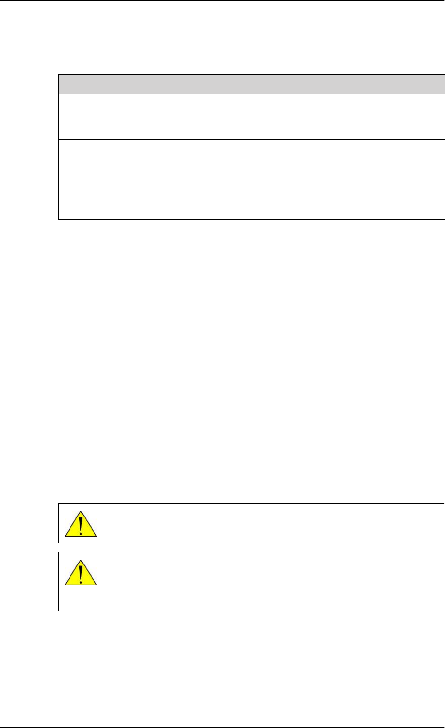
The following drawing shows the AVIATOR 200/300/350 cabin installation with connected
communication devices and available options:
Figure 2-1: Communication devices for the AVIATOR 200/300/350 system (example for a Level E
system)
SB-Lite.book Page 2 Tuesday, September 5, 2017 1:38 PM

General description
98-127093-H Chapter 2: Introduction to the AVIATOR 200/300/350 2-3
2222
Services
The SwiftBroadband services available depend on the type of antenna installed and the
current elevation angle to the satellite. The following table shows the services available for
the supported antenna types.
LGA (Class
15)a
Table 2-1: SwiftBroadband services for supported antenna types
a. The elevation needed for services with this antenna type is > 20°.
Standard IP
background
Up to
200 kbps
Up to
332 kbps
Up to 432 kbps
IP streaming
classes
8/16 8/16/32/64/
128 kbps
8/16/32/64/
128 kbps/X-Streamb
b. Data rates are up to 512 kbps. Check with your service provider for
activation.
Circuit-switched
standard voice
Yes Yes Yes
ISDN service or
3.1 kHz audio
(Premium voice)
No Elevation > 45° Yes
Multi-voice:
Number of voice
calls
1+1 (best
effort quality)
1+Up to 8
(best effort
quality)
1+Up to 8 (best
effort quality)
For current support of Inmarsat services check at
www.inmarsat.com/aviation/complete-aviation-connectivity/swiftbroadband.
The current elevation angle is shown in the web interface of the AVIATOR 200/300/350.
For ISDN service or 3.1 kHz audio and IGA the elevation angle must be larger than
45 degrees. Note that the ISDN phone service cannot be used by the AVIATOR 200
or the AVIATOR 200D.
PBX telephone exchange
The built-in PBX telephone exchange unit of the SBU connects two direct 2-wire POTS
interfaces for faxes, auxiliary phones, headset interface boxes etc., as well as an ISDN
interface for ISDN phones, fax machines or Secure communication. The built-in PBX of the
SBU can route VoIP calls that are terminated in the SIP server of the SBU.
SwiftBroadband
service
Satcom antenna
AVIATOR 200 AVIATOR 300
IGA (Class 7)
AVIATOR 350
HGA (Class 6)
SB-Lite.book Page 3 Tuesday, September 5, 2017 1:38 PM
General description
2-4 Chapter 2: Introduction to the AVIATOR 200/300/350 98-127093-H
Configuration Module (CM)
The Configuration Module (CM) for the SBU is inserted in the SBU and holds system and
user settings. It is designed as a “plug-in” module for the SBU, so the SBU can be replaced
while retaining all SBU and user settings. The SBU CM contains a permanently built-in SIM
card for access to the SwiftBroadband services.
Web interface for configuration
Use the built-in web interface of the SBU to access the SBU configuration settings in the
CM. A subset of the configuration settings are stored in a write-protected area of the CM.
This subset contains the physical settings for the antenna, cabling and other external input.
To set up or change the settings of the write-protected area you must connect a PC to the
connector marked Maintenance on the SBU front plate. You can view all settings from
any LAN or WLAN interface. For further information on the web interface, see
Configuration tasks on page 6-2.
Satcom antenna systems
The AVIATOR 200/300/350 system can be used with a wide range of satcom antennas. The
following table shows the Cobham SATCOM antennas that are compatible with the
AVIATOR 200/300/350.
Table 2-2: Satcom antenna types for the AVIATOR 200/300/350 system
System type Satcom antenna type
AVIATOR 200 TT-3002A LGA/LGA-3000
AVIATOR 300 TT-5006A IGA
IGA-5001
AVIATOR 350a
a. For backwards compatibility with previous Aero-SB Lite systems, the AVIATOR 350 can also
be used with TT-5006 IGA or IGA 5001, then the system is an AVIATOR 300.
HGA-6000/HGA-6500
HGA-7000/HGA-7001
An AVIATOR 200/300/350 system must only be used with satcom antennas that have
received type approval by Inmarsat.
Built-in router and Wireless (WLAN) option
The AVIATOR 200/300/350 system offers a built-in router as an option. With this option
multiple users and applications can use the system simultaneously. Without this option only
the first device that connects to the SBU will be allowed on the Internet.
The system also offers a built-in WLAN option for wireless communication devices and a
WLAN antenna approved for aeronautical use. This includes full WLAN routing
functionality.
If ordered, this option is enabled in the AVIATOR 200/300/350 from the factory. If these
options are not included from the start, the system can be upgraded at a later stage. Then
SB-Lite.book Page 4 Tuesday, September 5, 2017 1:38 PM

General description
98-127093-H Chapter 2: Introduction to the AVIATOR 200/300/350 2-5
2222
you receive the FLEX key for the purchased options and enter it in the AVIATOR 200/300/
350 web interface.
Built-in Multi-voice option1
The AVIATOR 200/300/350 system offers a built-in Multi-voice option. With this option
multiple calls can be made to and from the system simultaneously. Normally, the BGAN
system only supports one call at a time. With the built-in, optional Multi-voice service
enabled in your system, you can make multiple calls. The maximum number of concurrent
calls depends on your system, see Table 2-1 on page 2-3. If ordered, this option is enabled
in the AVIATOR 200/300/350 from the factory. If this option is not included from the start,
the system can be upgraded at a later stage. Then you receive the FLEX key for the
purchased options and enter it in the AVIATOR 200/300/350 web interface.
You must have Multi-voice in your airtime subscription, AVIATOR Wireless
Handset software version minimum 1.03 and SBU software version minimum
AVIATOR 200/300/350 (Level E): 1.07, AVIATOR 200D/300D/350D (Level D):
2.01, in order to support the Multi-voice function.
For information on how to set up Multi-voice, see Multi-voice (option) on page 6-91.
Built-in CMU/ACARS option1
The AVIATOR 200/300/350 system offers a built-in CMU/ACARS option. With this option it
is possible to connect a CMU or equivalent equipment to the SBU via A429 and send/
receive ACARS messages over SwiftBroadband. If ordered, this option is enabled in the
AVIATOR 200/300/350 from the factory. If this option is not included from the start, the
system can be upgraded at a later stage. Then you receive the FLEX key for the purchased
option(s) and enter it in the AVIATOR 200/300/350 web interface. For information on how
to set up CMU/ACARS, see Set up CMU/ACARS (option) on page 6-51.
SB-Safety Voice option2
With the SB-Safety (ICAO) Voice option you can make priority calls (priority level 1, 2 or 3)
to and from the cockpit. The 2-wire POTS connection is used for an external dialer and a
headset. The SB-Safety Voice service includes:
• Selecting the priority level before placing outgoing calls
• External pre-programmed speed dial numbers with embedded priority (optional)
• Handling priority level for active call
• Handling priority level for incoming call
• Annunciate the call status and SB-Safety Voice service availability via discrete outputs
To be able to use the SB-Safety Voice you must disable the WLAN access point and Multi-
Voice in the web interface. ISDN and the second 2-wire POTS interface are disabled when
using SB-Safety Voice. If this option is not included from the start, the system can be
upgraded at a later stage. Then you receive the FLEX key for the purchased option(s) and
enter it in the AVIATOR 200/300/350 web interface.
1. Supported from software version 1.07 for AVIATOR 200/300/350 (Level E) and 2.01 for AVIATOR 200/
300/350D (Level D).
Note
2. Supported from software version 4.00 for AVIATOR 200/300/350 (Level D).
SB-Lite.book Page 5 Tuesday, September 5, 2017 1:38 PM

General description
2-6 Chapter 2: Introduction to the AVIATOR 200/300/350 98-127093-H
Priority levels with an external dialer
If an external dialer is connected to the SBU, you can specify the priority level of outgoing
calls when entering phones numbers in the dialer’s directory.
Table 2-3: Priorities for SATVOICE calls (SB-Safety Voice)a
a. Advisory Circular AC No.20-150B of U.S. Department of Transportation Federal Aviation
Administration
Priority Level Application Category SATVOICE Call Examples
1
(highest) Safety of Flight
Distress and Urgency Inflight Emergency, Rapid
Emergency Descent,
Urgent Sidestep for
Weather
2
Operational High (second
highest) Safety of Flight
Flight Safety Altitude Request, ATC
Clearance/Instruction
3
Operational Low (third
highest) Safety of Flight
Regularity of Flight,
Meteorological
Administrative
Air Traffic Information
Service, AOC, Redispatch,
Maintenance
The priority level of a call can be part of the phone number. When dialing numbers, the
international call prefix can be changed to state the priority level: 01 for priority level 1, 02
for priority level 2 and 03 for priority level 3. Then the phone numbers look as follows
(example with 45 country code for Denmark):
• Priority level 1: 01 45 XX XX XX XX
• Priority level 2: 02 45 XX XX XX XX (or 00 45 XX XX XX XX)
• Priority level 3: 03 45 XX XX XX XX
No matter which priority level an outgoing phone call has, the phone number transferred to
the PBX is converted to the standard phone number using 00 as international call prefix.
The priority can be displayed on a connected annunciator panel.
Compatibility with IRIDIUM satellite phones
You can use the AVIATOR 200/300/350 system on aircraft with IRIDIUM satellite phones.
As Inmarsat satcom systems and Iridium satcom systems are using adjacent frequency
bands, there is a potential risk of interference when the Iridium system is used at the same
time as the Inmarsat system. To avoid this, two filters are needed:
• An Iridium Band Reject Filter, TT-5019A, must be inserted between the SBU and the
HLD.
• An INMARSAT Dual RF Filter, Aircell P/N P13167, must be inserted in the antenna coax
of the Iridium system.
For further information on installing the Iridium Band Reject Filer see TT-5019A Iridium
Band Reject Filter on page F-1.
SB-Lite.book Page 6 Tuesday, September 5, 2017 1:38 PM

General description
98-127093-H Chapter 2: Introduction to the AVIATOR 200/300/350 2-7
2222
2.1.2 AVIATOR 200/300/350 features
The AVIATOR 200/300/350 system has the following features:
The availability of some services depends on the satcom antenna type of the
system. Check the section Services on page 2-3 for an overview of services
available for LGA, IGA and HGA.
SwiftBroadband channel providing an ‘always on’ data connection of up to 432 kbps.
Full duplex, single or multi-user.
Automatic satellite selection.
Built-in PBX in the SBU interfacing to two 2-wire connections, one ISDN interface and
WLAN in the SBU, and integrated SIP server for VOIP telephony.
Standard voice.
3.1 kHz audio for modems, G3 fax, 14.4 kbps high quality voice etc.
ISDN voice for Secure communication, G4 fax etc.
ISDN data for video conferences etc.
Built-in Router option with DHCP, NAT for six Ethernet interfaces.
Built-in Wireless option (WLAN) IEEE 802.11 b/g.
Built-in Multi-voice option, up to 1+8 concurrent calls
Access to built-in web interface for daily use using LAN and WLAN.
Built-in CMU/ACARS option
Built-in web interface for configuration using the Maintenance connector on the SBU
front plate.
Does not affect the operation of an Iridium system.
SB-Safety Voice (cockpit voice) option (from software 4.00)
Note
SB-Lite.book Page 7 Tuesday, September 5, 2017 1:38 PM

General description
2-8 Chapter 2: Introduction to the AVIATOR 200/300/350 98-127093-H
Software versions
The AVIATOR 200/300/350 is shipped with software version 2.02. Software versions 2.03
and 4.00 are also available. The following tables show the features that are supported for
each software version.
Table 2-4: Available features for software versions (Level D)
Software
version Router Wifi CMU/ACARS Multi-voice A429
via RS422
SB-Safety
Voice
4.00 Yes Yesa
a. Not together with SB-Safety voice.
Yes YesaYes Yes
2.03 Yes Yes Yes Yes Yes -
2.02 Yes Yes Yes Yes - -
For Level E, the latest software version covered by this manual is version 1.09.
SB-Lite.book Page 8 Tuesday, September 5, 2017 1:38 PM
Application
98-127093-H Chapter 2: Introduction to the AVIATOR 200/300/350 2-9
2222
2.2 Application
2.2.1 Minimum system
A minimum working system has at least:
• one TT-5040A SBU
• one TT-5040A-001 CM
• one TT-5016A HLD
• one satcom antenna: LGA, IGA or HGA
The minimum wiring required for an AVIATOR 200/300/350 system is described in the
section Minimum system drawing on page 5-2.
The CM, HLD and some satcom antennas are powered by the SBU.
2.2.2 Part numbers
Applicable part numbers
This installation manual is for the AVIATOR 200/300/350 system and is applicable to the
part numbers in the following tables.
Part number Unit description
405040A SwiftBroadband Unit (SBU) [without CM] for AVIATOR 200/300/350
405040A-THD SwiftBroadband Unit (SBU) [without CM] for AVIATOR 200D/300D/
350D
405040A-838 Configuration Module (CM) for SBU for AVIATOR 200/200D
405040A-001 Configuration Module (CM) for SBU (no key and no options)
405040A-002 Built-in Router option
405040A-003 Built-in Wireless option
405040A-004 WLAN Antenna, optional (2 pieces recommended)
405040A-009 Built-in ACARS/SB Safety (ICAO) voice option
405040A-010 Built-in Multi-voice option
405040A-006 AVIATOR 350 Key (HGA/IGA)
405040A-007 AVIATOR 300 Key (IGA)
405040A-008 AVIATOR 200 Key (LGA)
Table 2-5: Part numbers
SB-Lite.book Page 9 Tuesday, September 5, 2017 1:38 PM
Application
2-10 Chapter 2: Introduction to the AVIATOR 200/300/350 98-127093-H
405016A High Power Amplifier/Low Noise Amplifier/Diplexer (HLD)
AVIATOR 200/300/350
405016A-THD High Power Amplifier/Low Noise Amplifier/Diplexer (HLD)
AVIATOR 200D/300D/350D
403002-001 Low Gain Antenna (LGA). Original Manufacturer Sensor Systems P/N:
S65-8282-101 (listed on FAA 8130-3).
405006A-PMA Intermediate Gain Antenna (IGA). Original Manufacturer Cobham P/N:
677-A0002 (listed on FAA 8130-3).
405621B-THW 2-Wire Handset (white)
405621B-THR 2-Wire Handset (black)
405622B-THW 2-Wire Cradle (white)
405622B-THR 2-Wire Cradle (black)
405019A Iridium Band Reject Filter
Part number Configuration module description
405040A-838 CM for SBU with A200 key
405040A-828 CM for SBU with A200 key, Router option(s)
405040A-818 CM for SBU with A200 key, WiFi option(s)
405040A-808 CM for SBU with A200 key, Router, WiFi option(s)
405040A-837 CM for SBU with A300 key
405040A-827 CM for SBU with A300 key, Router option(s)
405040A-817 CM for SBU with A300 key, WiFi option(s)
405040A-807 CM for SBU with A300 key, Router, WiFi option(s)
405040A-836 CM for SBU with A350 key
405040A-826 CM for SBU with A350 key, Router option(s)
405040A-816 CM for SBU with A350 key, WiFi option(s)
405040A-806 CM for SBU with A350 key, Router, WiFi option(s)
405040A-878 CM for SBU with A200 key, Multi voice option(s)
Table 2-6: Part numbers for configuration modules and options
Part number Unit description
Table 2-5: Part numbers (Continued)
SB-Lite.book Page 10 Tuesday, September 5, 2017 1:38 PM
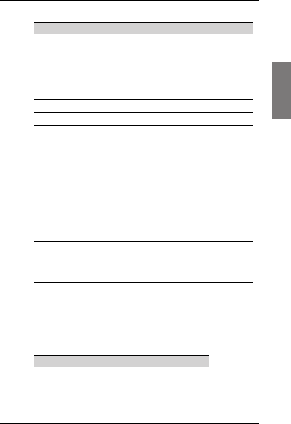
Application
98-127093-H Chapter 2: Introduction to the AVIATOR 200/300/350 2-11
2222
The flex keys for A350 can also be used in A300 systems.
The SwiftBroadband Unit (SBU) and the High Power Amplifier, Low Noise Amplifier and
Diplexer (HLD) must all be level E or level D approved. No mismatch is allowed.
Circuit breaker
405040A-868 CM for SBU with A200 key, Router, Multi voice option(s)
405040A-858 CM for SBU with A200 key, WiFi, Multi voice option(s)
405040A-848 CM for SBU with A200 key, Router, WiFi, Multi voice option(s)
405040A-876 CM for SBU with A350 key, Multi voice option(s)
405040A-866 CM for SBU with A350 key, Router, Multi voice option(s)
405040A-856 CM for SBU with A350 key, WiFi, Multi voice option(s)
405040A-846 CM for SBU with A350 key, Router, WiFi, Multi voice option(s)
405040A-8B6 CM for SBU with A350 key, ACARS/SB Safety (ICAO) voice option(s)
405040A-8A6 CM for SBU with A350 key, Router, ACARS/SB Safety (ICAO) voice
option(s)
405040A-896 CM for SBU with A350 key, WiFi, ACARS/SB Safety (ICAO) voice
option(s)
405040A-886 CM for SBU with A350 key, Router, WiFi, ACARS/SB Safety (ICAO)
voice option(s)
405040A-8F6 CM for SBU with A350 key, Multi voice, ACARS/SB Safety (ICAO) voice
option(s)
405040A-8E6 CM for SBU with A350 key, Router, Multi voice, ACARS/SB Safety
(ICAO) voice option(s)
405040A-8D6 CM for SBU with A350 key, WiFi, Multi voice, ACARS/SB Safety (ICAO)
voice option(s)
405040A-8C6 CM for SBU with A350 key, Router, WiFi, Multi voice, ACARS/SB Safety
(ICAO) voice option(s)
Part number Configuration module description
Table 2-6: Part numbers for configuration modules and options (Continued)
Part number Recommended aircraft circuit breakers
2TC2-7.5 Klixon 2TC series, 7.5 A current rating (SBUa)
a. The CM, HLD and some satcom antennas are powered by the SBU.
Table 2-7: Part numbers for Klixon circuit breaker
SB-Lite.book Page 11 Tuesday, September 5, 2017 1:38 PM
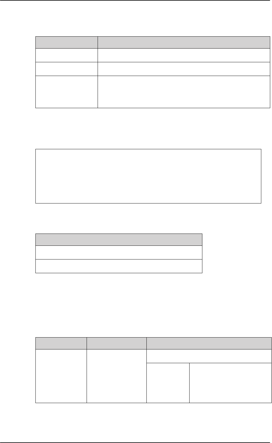
Application
2-12 Chapter 2: Introduction to the AVIATOR 200/300/350 98-127093-H
Trays and connectors
Installation kits
For installation kits for the AVIATOR 200/300/350 system contact:
Table 2-9: Installation kits, contact information
ECS offers an installation kit for the SBU (ECS part number: 120-20027-102).
2.2.3 Applicable external units
The AVIATOR 200/300/350 system can be used with the external units listed below. Note
that the AVIATOR 200/300/350 system may also be able to interface to other units not
listed below.
Part number Approved tray
PO299-101 ECS Tray Assembly 1/4-size ATR (for SBU)
MT4-2346-101 EMTEQ Tray Assembly 1/4-size ATR (for SBU)
DPX2NA-67322-606
(old number:
DPX2NA-67322-500)
Required Connector Kit for SBU tray: ITT Cannon Connector,
Dual Plug, contact arrangement top: 33C4, bottom: 33C4.
Table 2-8: Part number for connector
ECS, a Carlisle IT company, USA
Phone (Franklin, WI): +1 800-327-9473
Phone (Kent, WA): +1 800-227-5953
E-mail: sales@CarlisleIT.com
Home page: www.CarlisleIT.com
EMTEQ (B/E Aerospace)
Home page: www.emteq.com
Contact info: www.emteq.com/contact-
us.php
Item in installation kit
1 ARINC connector, SBU (DPX2NA-67322-606)
1 Tray Assembly, SBU, 1/4-size ATR W/DPX2 (P0299-101)
Table 2-10: Basic installation kits from ECS for the SBU
Product name Product description Manufacturer
ICG DECT
Cordless Handset
Cordless handset
system
ICG, USA
Phone:
E-mail:
Home page:
1-800-279-1991 or
(757)947-1030
sales@icg.aero
www.icg.aero
Table 2-11: List of applicable external units
SB-Lite.book Page 12 Tuesday, September 5, 2017 1:38 PM

Application
98-127093-H Chapter 2: Introduction to the AVIATOR 200/300/350 2-13
2222
Sigma7Handset system ICG (see contact info above)
PTA-12 Airborne Telephone
Adaptor
Northern Airborne Technology Ltd.
1925 Kirschner Road
Kelowna, BC Canada V1Y 4N7
Phone:
Toll Free:
Fax:
(250) 763-2232
(888) 763-2232
(250) 762-3374
MD41-1948 Switch Annunciator
Panel
MID-CONTINENT INSTRUMENT CO.,
INC.
9400 E. 34th. St. North
Wichita, KS 67226-2615
Phone:
Fax:
Home page:
316-630-0101
316-630-0723
www.mcico.com
AirCell Axxess Iridium Telephone
System
Aircell Business Aviation Services LLC
303 south Technology Court, Bldg.A
Broomfield, CO 80021
Phone:
Fax:
E-mail:
+1.303.301.3200
+1.303.301.3201
sales@aircell.com
AIS 380 Aircraft
Interface Module
Converter RS-422 to
A429
Shadin Avionics
6831 Oxford St
St Louis Park MN 55426
www.shadin.com/
Manufacturer part number: 833640-00
Cobham SATCOM part number: 405017A-801
Product name Product description Manufacturer
Table 2-11: List of applicable external units
SB-Lite.book Page 13 Tuesday, September 5, 2017 1:38 PM
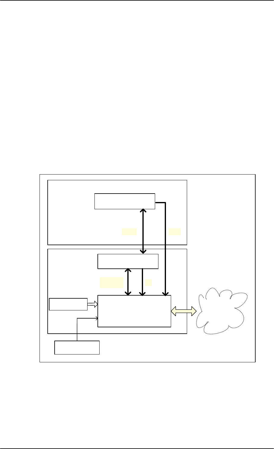
System block diagrams
2-14 Chapter 2: Introduction to the AVIATOR 200/300/350 98-127093-H
2.3 System block diagrams
The following block diagrams and the wiring diagrams in section 5.3.3 show examples of
satcom antennas that can be connected to the AVIATOR 200/300/350 systems.
In order to use the satcom antenna with the AVIATOR 200/300/350 systems, the specific
antenna type and the AVIATOR 200/300/350 system must be Type Approved by Inmarsat
as a combined system. The satcom antenna types supported are listed in Satcom antenna
systems on page 2-4. AVIATOR 200/300/350 systems will be Inmarsat Type Approved
with more antennas as requested by market requirements. Contact your Cobham SATCOM
sales/support representative for the latest status on Inmarsat Type Approvals for satcom
antennas for the AVIATOR 200/300/350 system.
The following block diagrams show the basic system component interconnection and the
user interfaces.
2.3.1 AVIATOR 200 system with LGA-3000 antenna
The drawing below shows the AVIATOR 200 system with an LGA antenna.
Figure 2-2: System configuration with LGA-3000 antenna
/*$
77$+/'
$QWHQQD
77$6%8
,56*16613,
$9,$725
77$
&0
8VHU
,QWHUIDFHV
5[
5[7[
7[0RGHP
9'&
*36
SB-Lite.book Page 14 Tuesday, September 5, 2017 1:38 PM
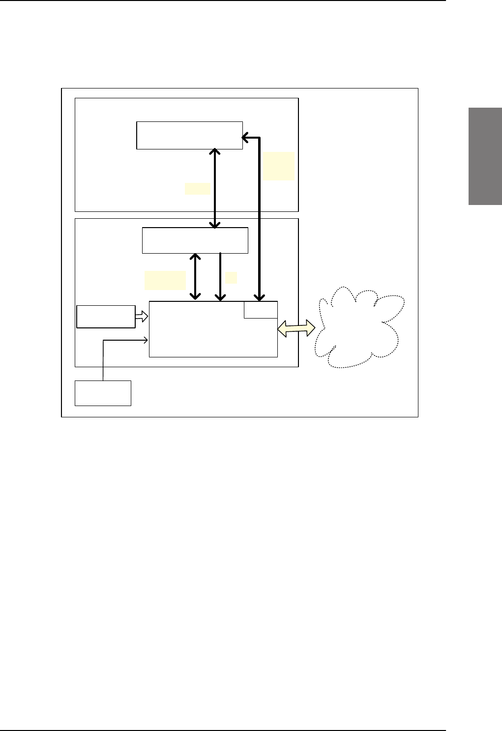
System block diagrams
98-127093-H Chapter 2: Introduction to the AVIATOR 200/300/350 2-15
2222
2.3.2 AVIATOR 300 system with TT-5006A IGA antenna
The drawing below shows the AVIATOR 300 system with in IGA antenna.
Figure 2-3: System configuration with TT-5006A IGA antenna
77$
ZLWK156
77$+/'
$QWHQQD
77$6%8
$+56,56
RSWLRQDO
$9,$725
V\VWHP
77$
&0
8VHU
,QWHUIDFHV
5[
5[7[
%68
7[0RGHP
9'&
0RGHP
*365)
9'&
SB-Lite.book Page 15 Tuesday, September 5, 2017 1:38 PM
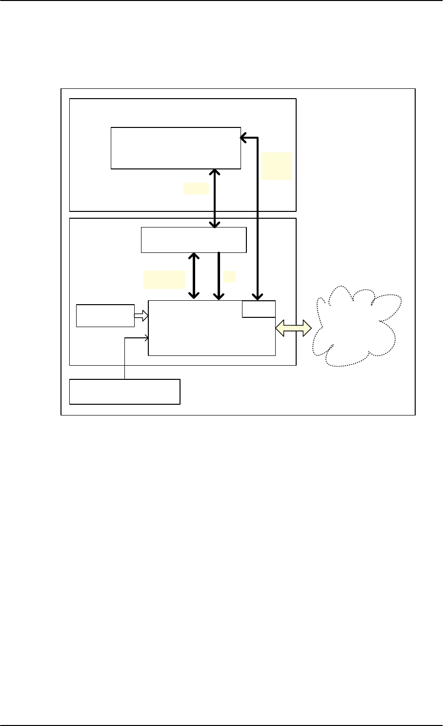
System block diagrams
2-16 Chapter 2: Introduction to the AVIATOR 200/300/350 98-127093-H
2.3.3 AVIATOR 350 system with Cobham antennas
The drawing below shows the AVIATOR 350 system with Cobham antennas.
Figure 2-4: System configuration with Cobham antennas
&REKDP+*$
&REKDP+*$
77$+/'
$QWHQQD
77$6%8
$+56,56
$9,$725
V\VWHP
77$
&0 8VHU
,QWHUIDFHV
5[
5[7[
%68
7[0RGHP
9'&
0RGHP
*365)
9'&
SB-Lite.book Page 16 Tuesday, September 5, 2017 1:38 PM
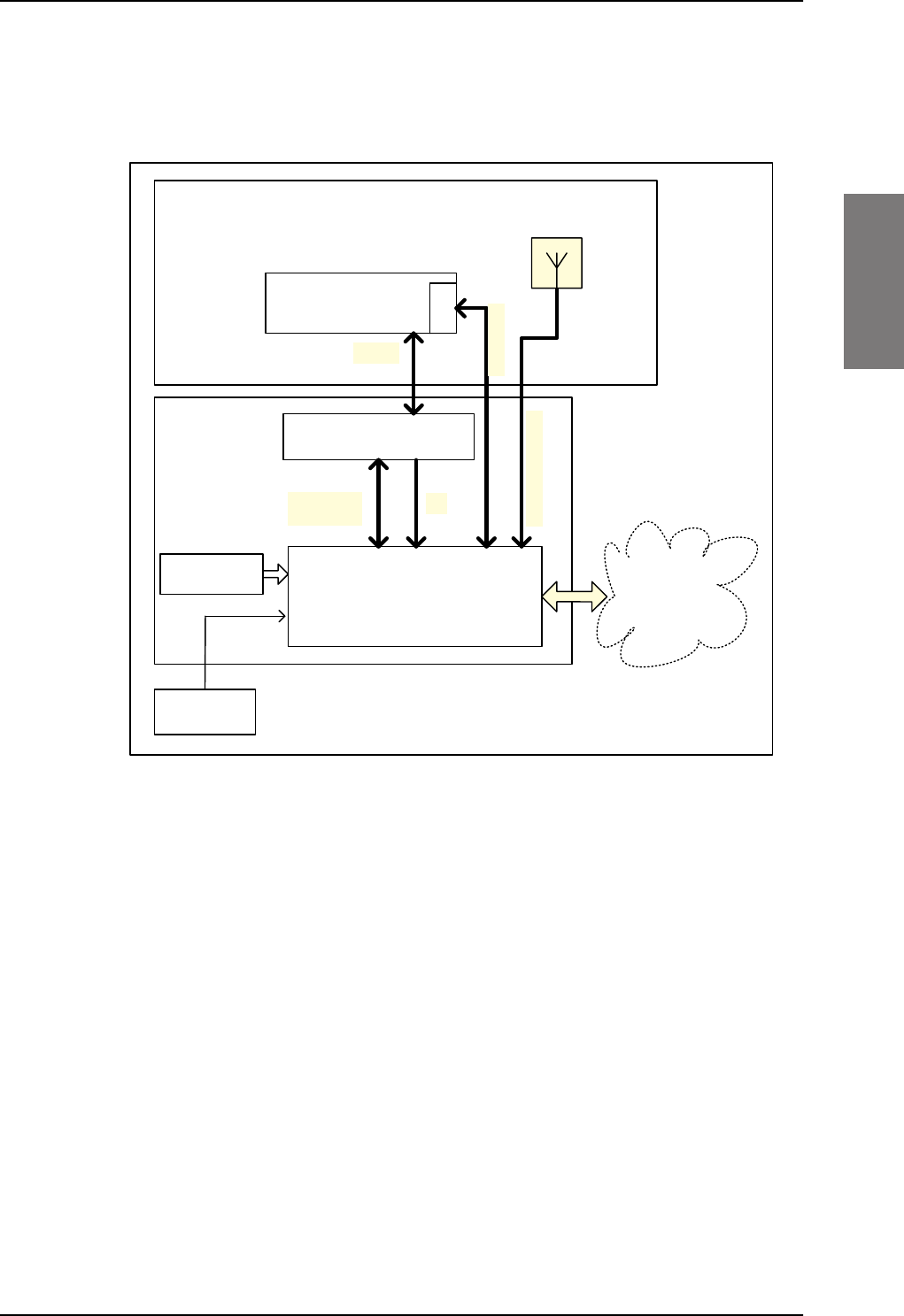
System block diagrams
98-127093-H Chapter 2: Introduction to the AVIATOR 200/300/350 2-17
2222
2.3.4 AVIATOR 350 system with ARINC-741/781 antennas
The drawing below shows the AVIATOR 350 system with an ARINC-741/781 HGA.
For detailed description of the connection of each antenna type, see Wiring the satcom
antenna on page 5-10.
Figure 2-5: System configuration ARINC 429 antennas
$5,1&
+*$
77$+/'
$QWHQQD
77$6%8
$+56,56
$9,$725
V\VWHP
77$
&0 8VHU
,QWHUIDFHV
5[
5[7[
7[0RGHP
9'&
$5,1&
%68
,QVWDOO([WHUQDODFWLYH*36
$QWHQQDZLWK6DW&RPILOWHU
LI$+56LVXVHG
*369RU9GF
SB-Lite.book Page 17 Tuesday, September 5, 2017 1:38 PM
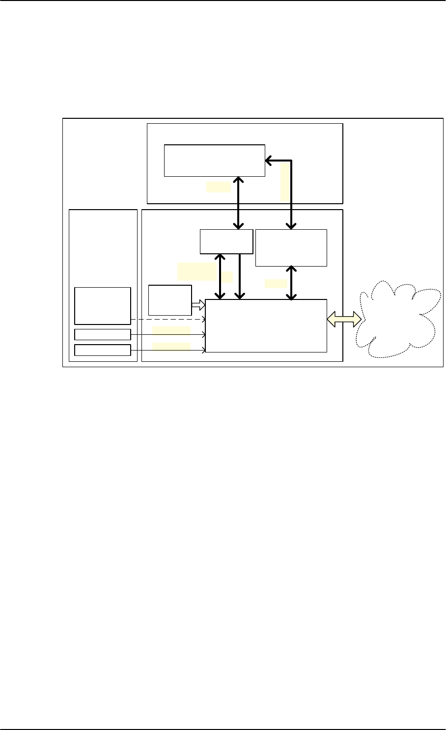
System block diagrams
2-18 Chapter 2: Introduction to the AVIATOR 200/300/350 98-127093-H
2.3.5 AVIATOR 350D system with ACARS option and ARINC-741/781
ant.
The drawing below shows the AVIATOR 350 system with the HGA-6000/6500 and AMT-50
and ACARS/B Safety (ICAO) voice.
For detailed description of the connection of each antenna type, see Wiring the satcom
antenna on page 5-10.
Figure 2-6: System configuration ARINC 429 antennas
$5,1&
$5,1&
$5,1&$QWHQQD
77$
+/'
$QWHQQDVXEV\VWHP
77$6%8
$+56,56
$9,$725'
V\VWHP
77$
[\
&0
5[
5[7[
7[0RGHP
9'&
$5,1&
8VHU
,QWHUIDFHV
$+56,56
56WR$5,1&
&RQYHUWHU
56
1DYLJDWLRQDO
VXEV\VWHP
([WHUQDO*36
DQWHQQD
LI$+56LV
XVHG
SB-Lite.book Page 18 Tuesday, September 5, 2017 1:38 PM
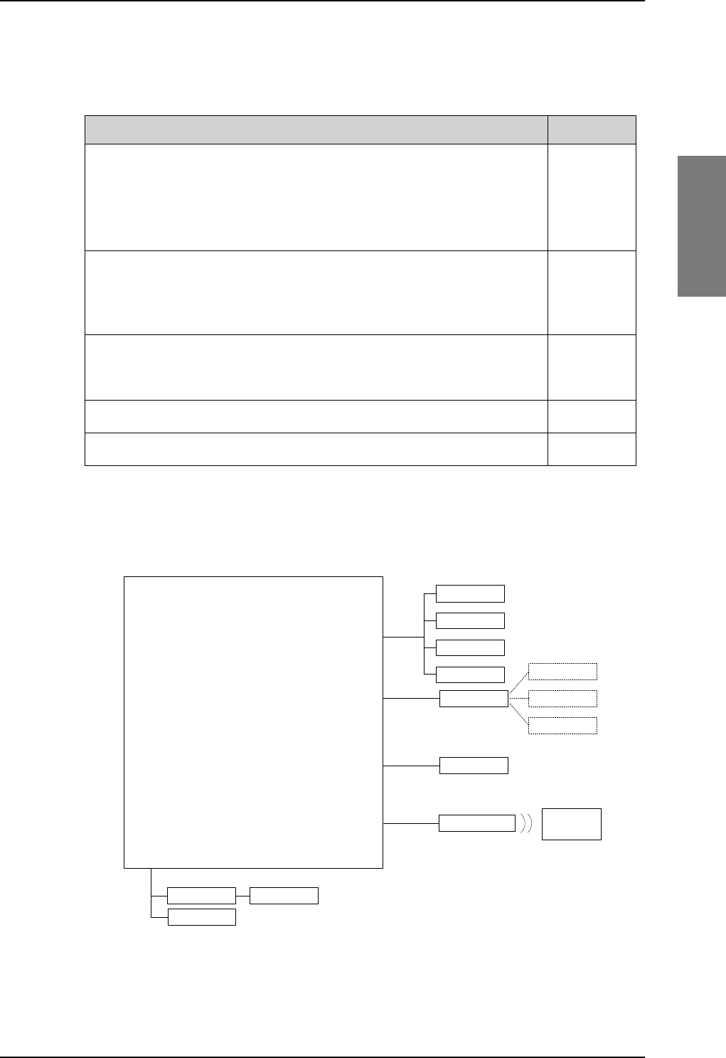
System block diagrams
98-127093-H Chapter 2: Introduction to the AVIATOR 200/300/350 2-19
2222
2.3.6 User interfaces
The AVIATOR 200/300/350 system has the following user interfaces:
Table 2-12: AVIATOR 200/300/350 user interfaces
Interfaces Number
2-wire POTS interface
This interface can be used for the TT-5621B 2-Wire Handset and TT-
5622B 2-Wire Cradle or other POTS handsets. The TT-5622B 2-Wire
Cradle has an RJ11 connector to which additional 2-wire terminals can be
connected, e.g. for fax or modem data.
2
10/100BaseT Ethernet interfaces for connecting IP equipment.
Note that the SBU has a Built-in Router option. The SBU has an additional
Ethernet interface for system configuration (Maintenance connector on
the SBU front plate, not shown in the following figure).
6
Built-in Wireless Option with two WLAN antenna interfaces for diversity
operation to connect WiFi-enabled equipment like lap tops, PDAs or VOIP
handsets.
1
(32 devices)
Euro ISDN S-bus interface for PC, Fax or STE (without DC power support)a
a. Note that the ISDN data service (UDI/RDI) cannot be used by the AVIATOR 200 nor the
AVIATOR 200D.
1
Discrete outputs for annunciators 4
The following figure shows most of the possible user interfaces.
Figure 2-7: AVIATOR 200/300/350 interfaces
Note that the ISDN data service (UDI/RDI) cannot be used by the AVIATOR 200 nor the
AVIATOR 200D.
77$6%8
,3(TXLSPHQW
,6'1
(WKHUQHW
$QQXQFLDWRUV
'LVFUHWH
2XWSXWV
*)D[
:&UDGOH :+DQGVHW
,3GHYLFH
,3GHYLFH
,3GHYLFH
:/$1DQWHQQD
:LUHOHVV,3
HTXLSPHQW
GHYLFHV
ZLUH
5-
:/$1
,6'1SKRQH
*)D[
3&5RXWHU
9LGHRSKRQH
SB-Lite.book Page 19 Tuesday, September 5, 2017 1:38 PM

System block diagrams
2-20 Chapter 2: Introduction to the AVIATOR 200/300/350 98-127093-H
SB-Lite.book Page 20 Tuesday, September 5, 2017 1:38 PM

98-127093-H 3-1
Chapter 3
3333
Equipment drawings 3
3.1 Introduction
The following pages show copies of outline drawings of important system units relevant for
an installation.
For equipment drawings of the AVIATOR Wireless Handset and Cradle see
AVIATOR Wireless Handset and Cradle Installation & Maintenance Manual (98-
129600).
Important The drawings in this manual are for reference only. If you have access to the
partner platform Cobham SYNC, you can get copies of the outline drawings
at: https://sync.cobham.com/satcom/support/downloads. You can download
the drawings as PDF files. There are also 3D models of selected units.
Note
SB-Lite.book Page 1 Tuesday, September 5, 2017 1:38 PM
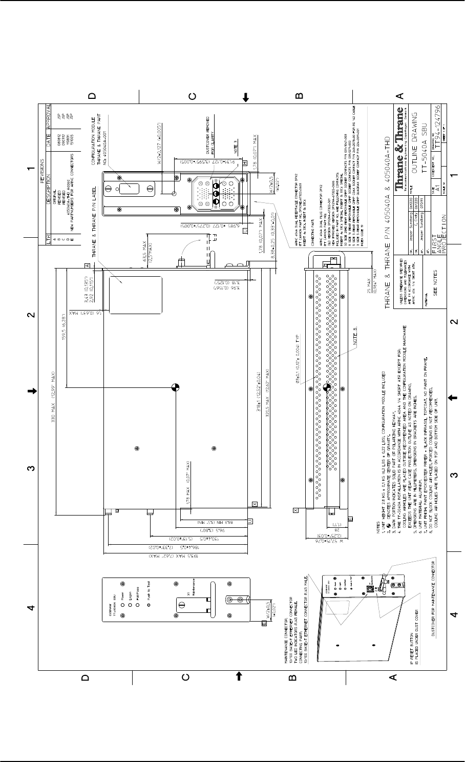
TT-5040A SBU
3-2 Chapter 3: Equipment drawings 98-127093-H
3.2 TT-5040A SBU
Figure 3-1: Outline drawing: TT-5040A SBU
SB-Lite.book Page 2 Tuesday, September 5, 2017 1:38 PM
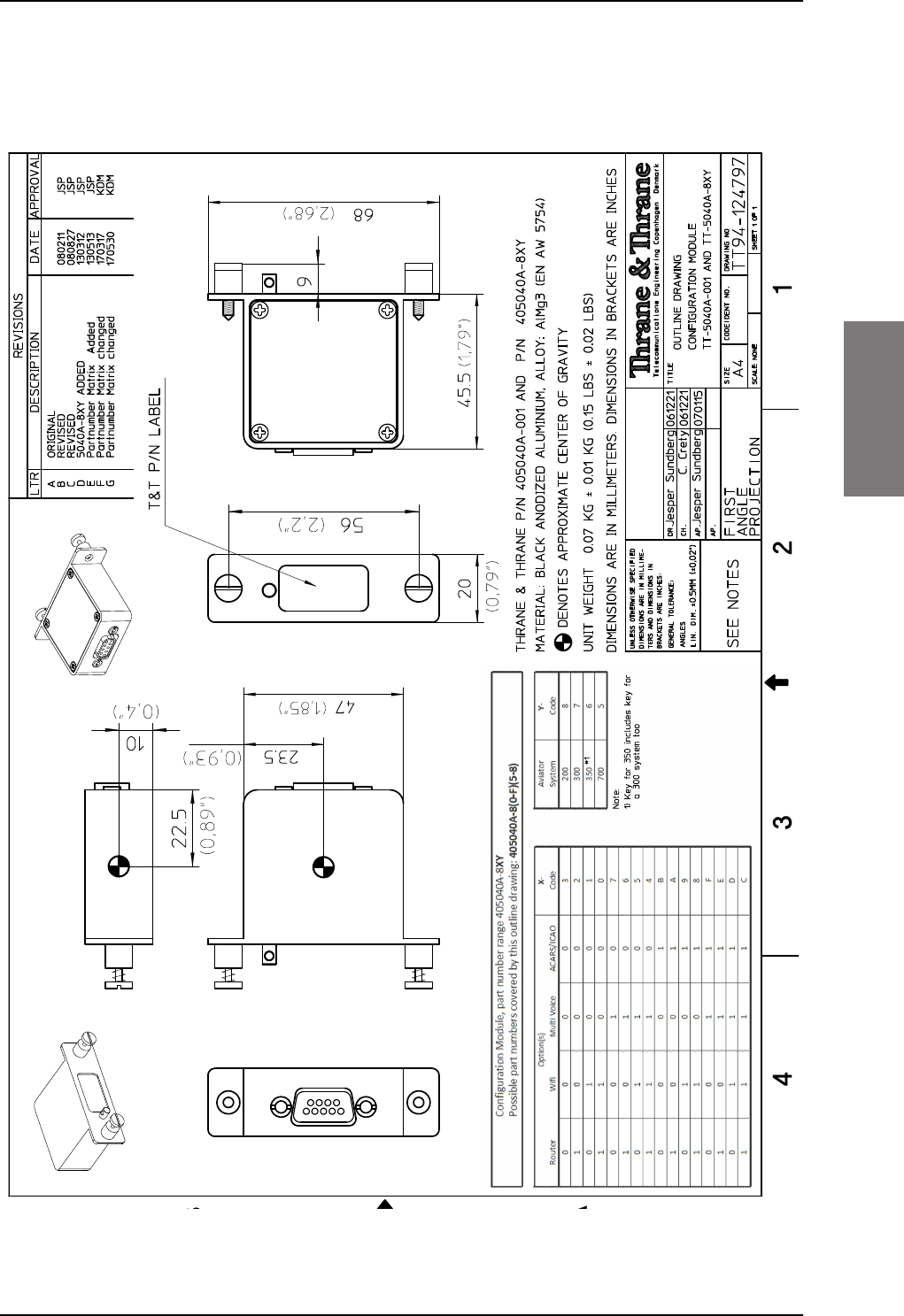
TT-5040A SBU
98-127093-H Chapter 3: Equipment drawings 3-3
3333
3.2.1 TT-5040A-001 CM (inserted in the SBU)
Figure 3-2: Outline drawing: TT-5040A-001 CM, inserted in the SBU
SB-Lite.book Page 3 Tuesday, September 5, 2017 1:38 PM
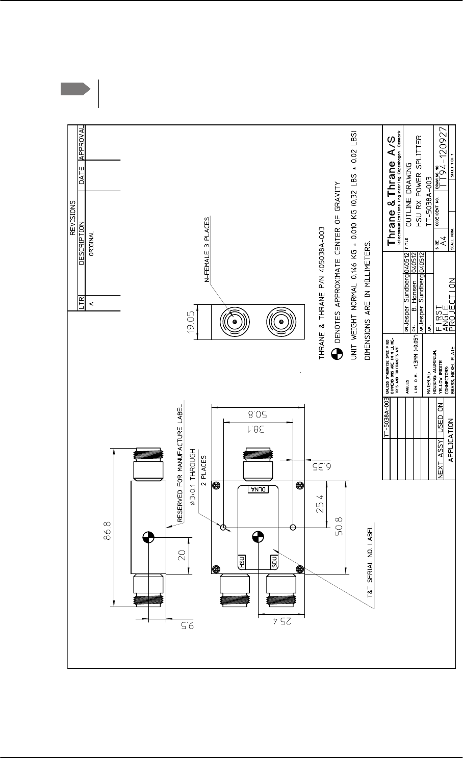
TT-5038A-003 Rx Power Splitter
3-4 Chapter 3: Equipment drawings 98-127093-H
3.3 TT-5038A-003 Rx Power Splitter
Note If the Rx Power Splitter is to be mounted on a flat surface, mount it on a 3 mm
mounting plate to provide enough space for mounting of the connectors.
Figure 3-3: Outline Drawing: Rx Power Splitter
SB-Lite.book Page 4 Tuesday, September 5, 2017 1:38 PM
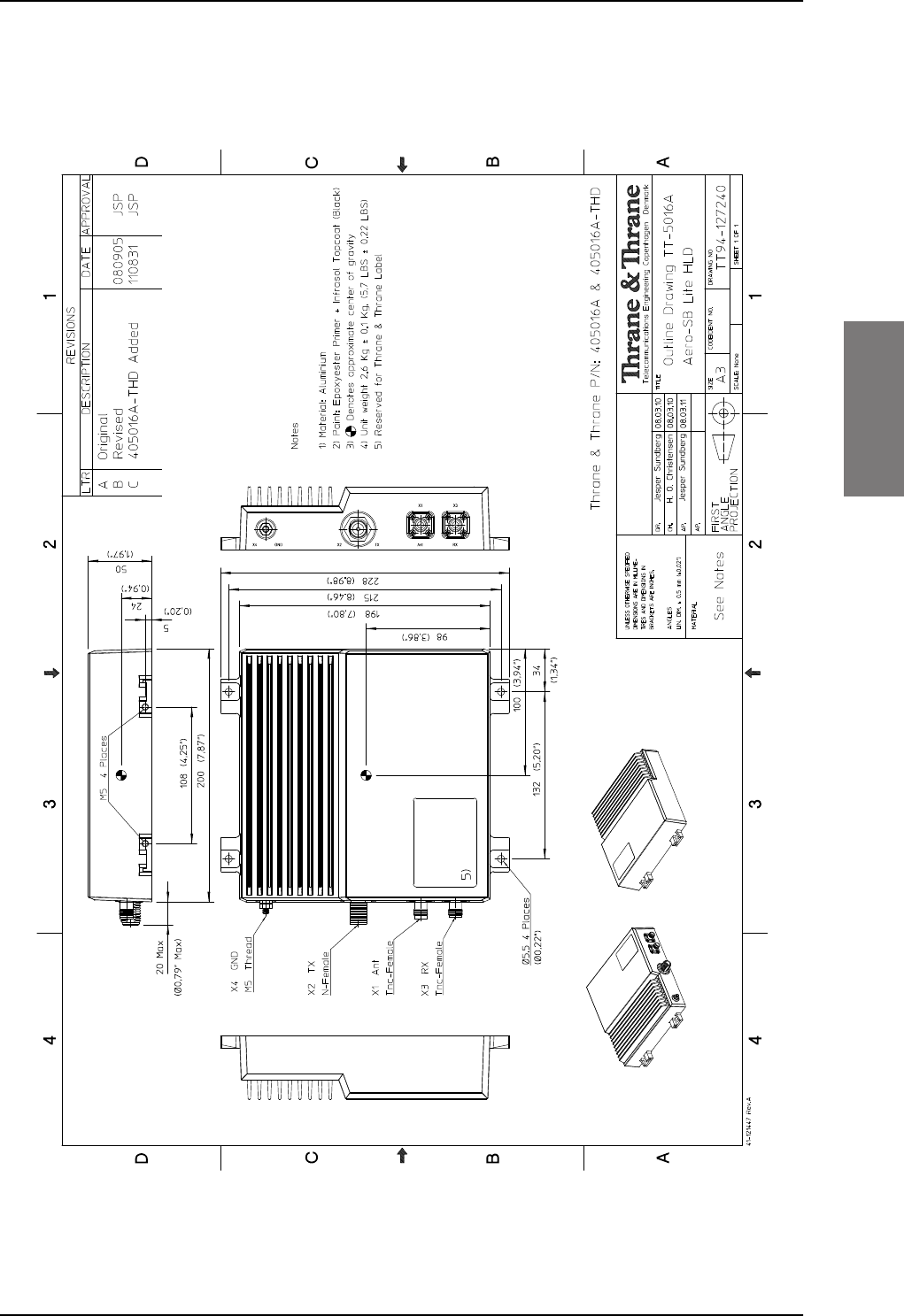
TT-5016A HLD
98-127093-H Chapter 3: Equipment drawings 3-5
3333
3.4 TT-5016A HLD
Figure 3-4: Outline drawing: TT-5016A HLD
SB-Lite.book Page 5 Tuesday, September 5, 2017 1:38 PM
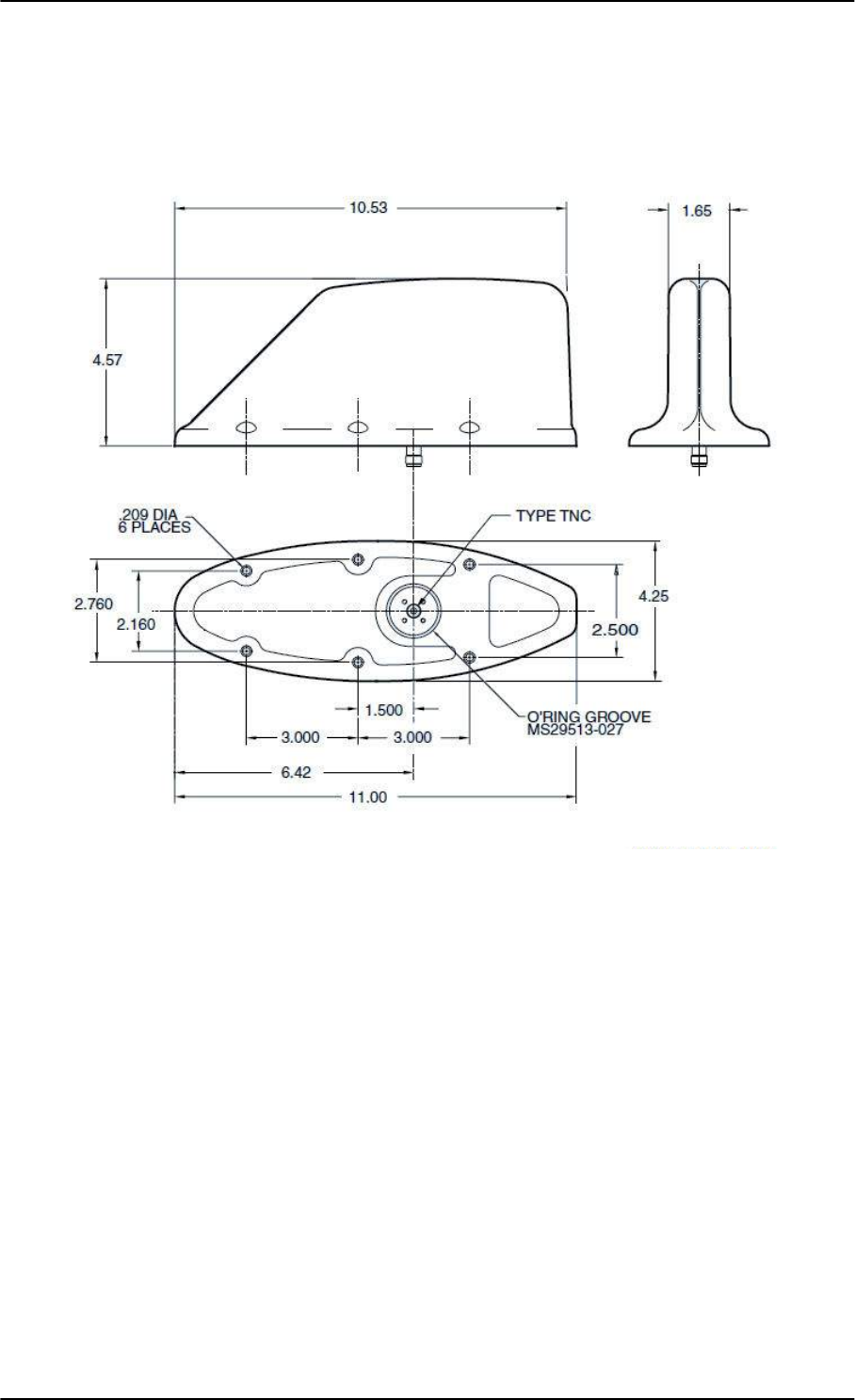
TT-3002A LGA
3-6 Chapter 3: Equipment drawings 98-127093-H
3.5 TT-3002A LGA
Original Manufacturer Sensor Systems P/N: S65-8282-101 (listed on FAA 8130-3).
Figure 3-5: Outline drawing: TT-3002A LGA
For newest revision check at http://www.sensorantennas.com.
Dimensions in inch.
SB-Lite.book Page 6 Tuesday, September 5, 2017 1:38 PM
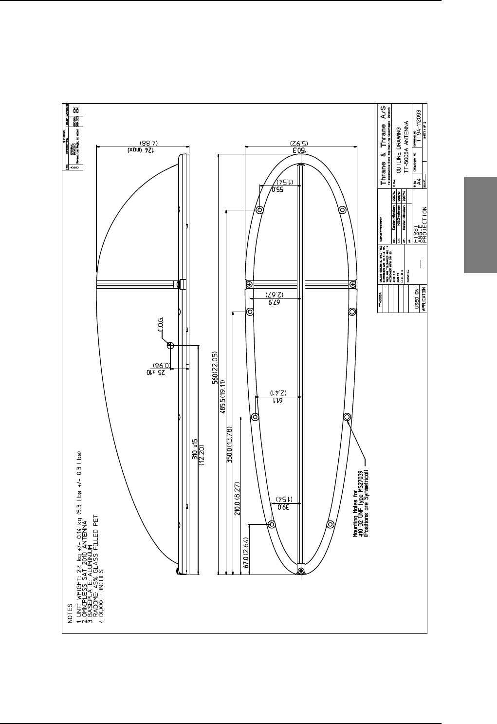
TT-5006A IGA
98-127093-H Chapter 3: Equipment drawings 3-7
3333
3.6 TT-5006A IGA
Original Manufacturer Cobham P/N: 677-A0002 (listed on FAA 8130-3).
Figure 3-6: Outline drawing: TT-5006A IGA antenna
SB-Lite.book Page 7 Tuesday, September 5, 2017 1:38 PM
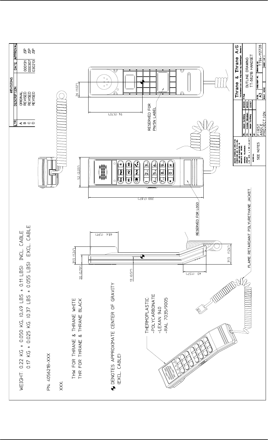
TT-5621B 2-Wire Handset
3-8 Chapter 3: Equipment drawings 98-127093-H
3.7 TT-5621B 2-Wire Handset
Figure 3-7: Outline drawing: TT-5621B 2-Wire Handset
SB-Lite.book Page 8 Tuesday, September 5, 2017 1:38 PM
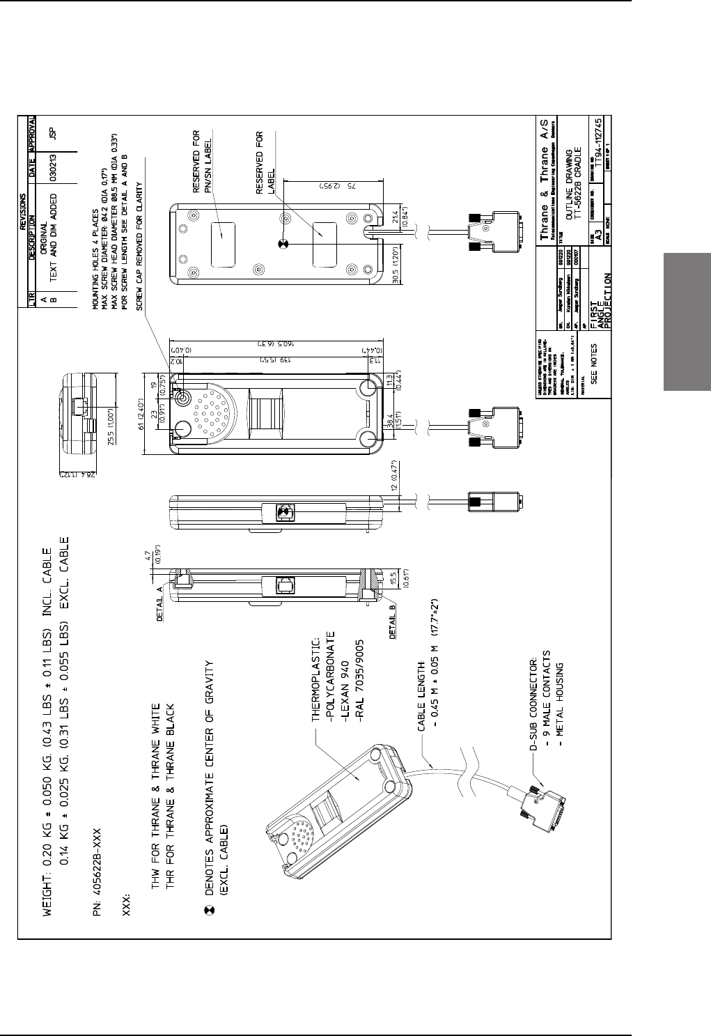
TT-5622B 2-Wire Cradle
98-127093-H Chapter 3: Equipment drawings 3-9
3333
3.8 TT-5622B 2-Wire Cradle
Figure 3-8: Outline drawing: TT-5622B 2-Wire Cradle
SB-Lite.book Page 9 Tuesday, September 5, 2017 1:38 PM
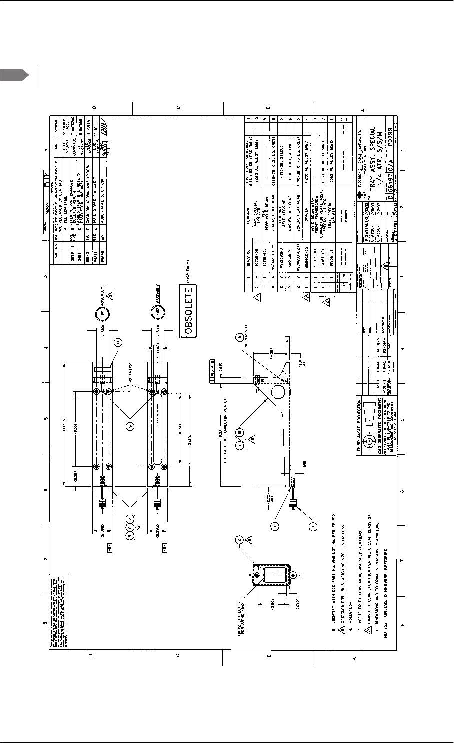
SBU trays
3-10 Chapter 3: Equipment drawings 98-127093-H
3.9 SBU trays
The comment OBSOLETE refers to the -102 assembly.
Figure 3-9: Outline drawing: SBU tray: ECS PO299-101
Note
SB-Lite.book Page 10 Tuesday, September 5, 2017 1:38 PM
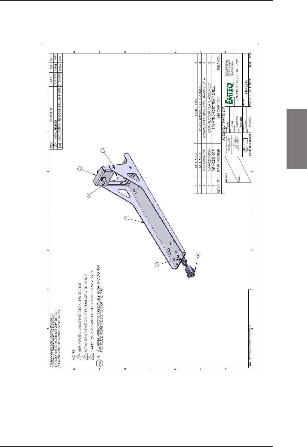
Figure 3-10: Outline drawing: SBU tray: EMTEQ MT4-2346-101 (page 1)
SBU trays
98-127093-H Chapter 3: Equipment drawings 3-11
3333
SB-Lite.book Page 11 Tuesday, September 5, 2017 1:38 PM
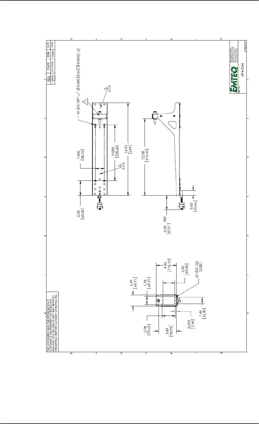
Figure 3-11: Outline drawing: SBU tray: EMTEQ MT4-2346-101 (page 2)
SBU trays
3-12 Chapter 3: Equipment drawings 98-127093-H
SB-Lite.book Page 12 Tuesday, September 5, 2017 1:38 PM
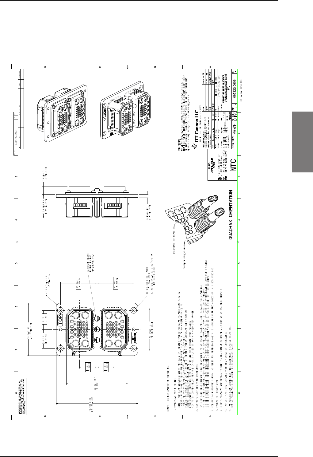
SBU tray connector
98-127093-H Chapter 3: Equipment drawings 3-13
3333
3.10 SBU tray connector
For correct index pin codes for the SBU see Figure 4-2: SBU rear receptacle, engaging
end (Index code: 19).
Figure 3-12: Outline drawing: SBU tray connector: ITT Cannon DPX2NA-67322-606
Export Administration Regulations (15 CFR 730, et seq.). Any transfer of this data to non-US persons or to any location outside the United States must be in compliance with the Export Administration Regulations.
This document contains technical data that is subject to export controls under the Export Administration Act and
EXPORT CODE C
SB-Lite.book Page 13 Tuesday, September 5, 2017 1:38 PM
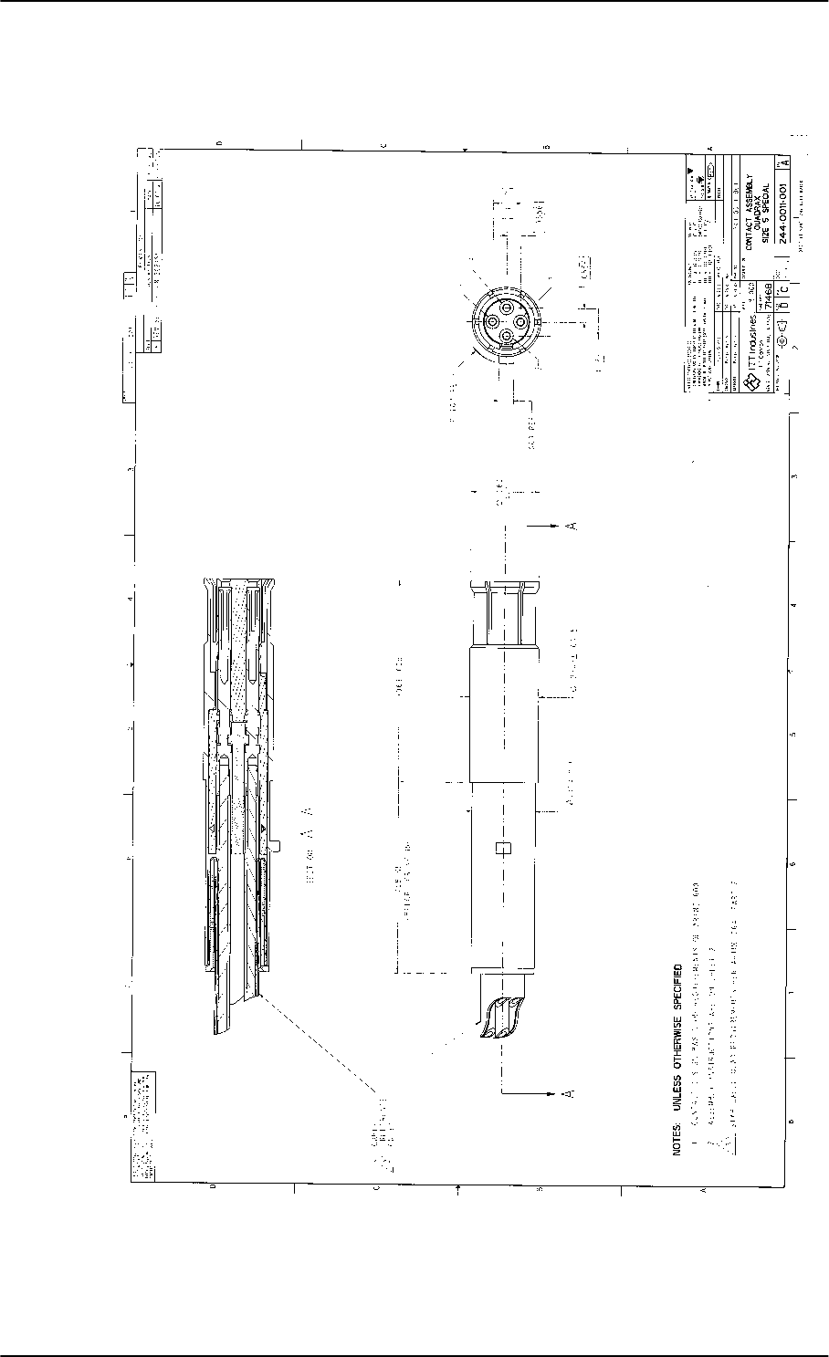
Contact Assembly: Quadrax Pin size 5 special
3-14 Chapter 3: Equipment drawings 98-127093-H
3.11 Contact Assembly: Quadrax Pin size 5 special
Figure 3-13: Contact Assembly: Quadrax Pin size 5 special: ITT Cannon 244-0011-001
SB-Lite.book Page 14 Tuesday, September 5, 2017 1:38 PM
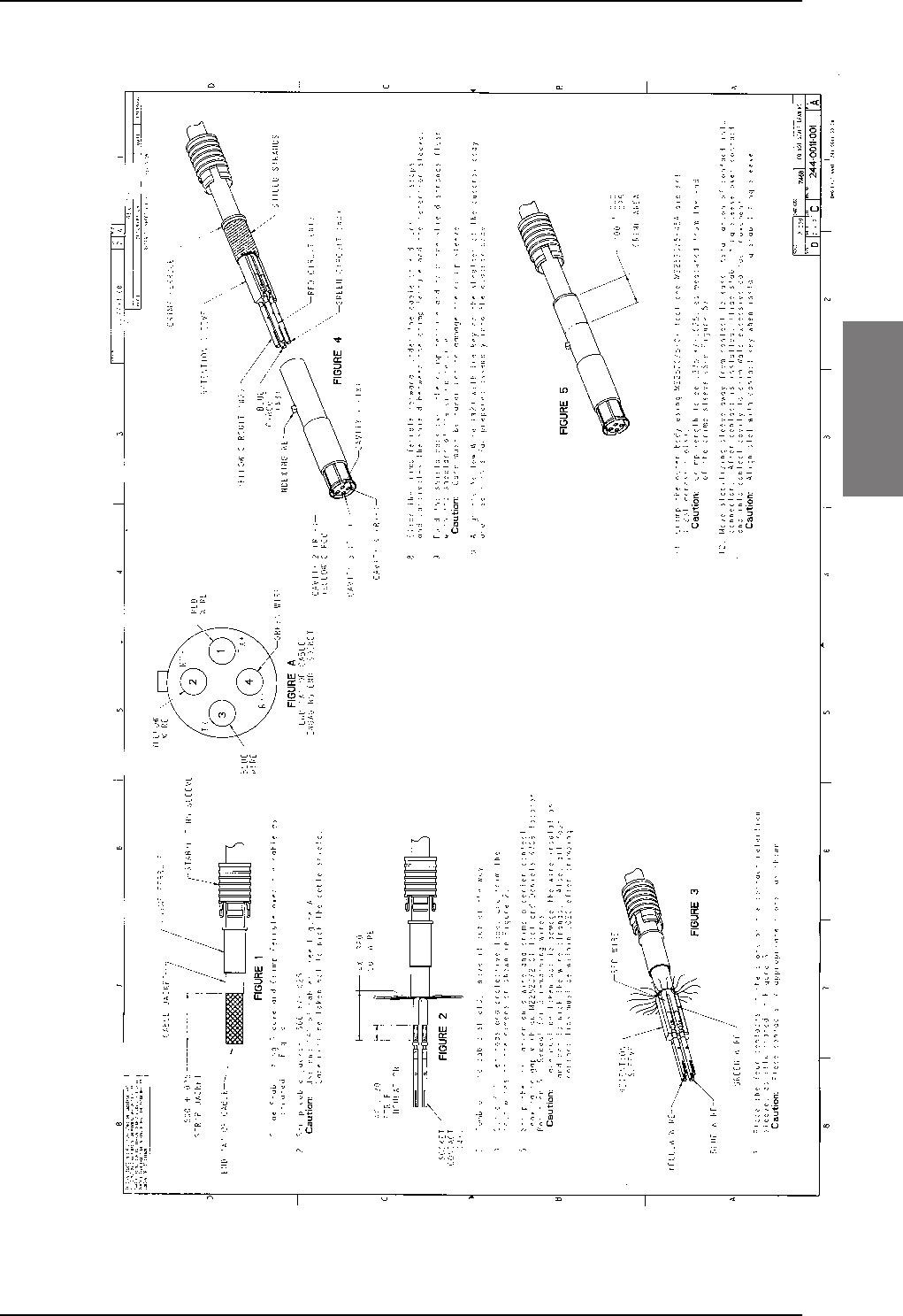
Contact Assembly: Quadrax Pin size 5 special
98-127093-H Chapter 3: Equipment drawings 3-15
3333
Figure 3-13: Contact Assembly: Quadrax Pin size 5 special: ITT Cannon 244-0011-001 (Continued)
SB-Lite.book Page 15 Tuesday, September 5, 2017 1:38 PM
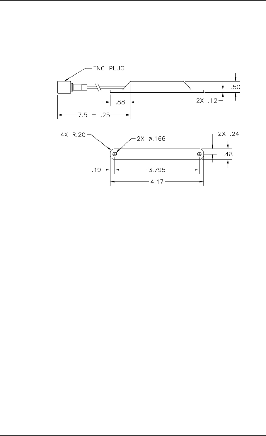
TT-5040A-004 WLAN antenna
3-16 Chapter 3: Equipment drawings 98-127093-H
3.12 TT-5040A-004 WLAN antenna
Original Manufacturer P/N: VT Miltope 901167-2.
Figure 3-14: Outline drawing: TT-5040A-004 WLAN antenna
Measures are in inches.
SB-Lite.book Page 16 Tuesday, September 5, 2017 1:38 PM
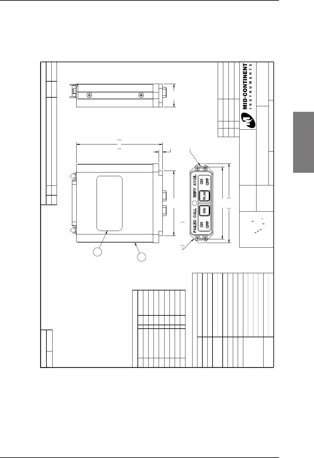
Switch Annunciator Panel
98-127093-H Chapter 3: Equipment drawings 3-17
3333
3.13 Switch Annunciator Panel
Original Manufacturer P/N: MD41-1948.
Figure 3-15: Outline drawing: Switch Annunciator panel
MD41-1948
This document discloses proprietary information
of Mid-Continent Instrument Co. It may be
reproduced or disclosed only with written
permission of Mid-Continent Instrument Co. and
is not to be used in any way detrimental to the
interests of Mid-Continent Instrument Co.
11
UNLESS OTHERWISE
SPECIFIED, ALL DIMENSIONS
ARE IN INCHES.
TOLERANCE:
FRACTIONAL= 1/64
.XX= 0.015
.XXX= 0.005
.XXXX= 0.002
ANGULAR= 0.5
CONCENTRICITY: 0.005 TIR
BREAK ALL SHARP EDGES
THREADS PER MIL-S-7742
Annunciation Control Unit
3/24/2009
C. Mies
1:1 of
PART NUMBER:
TITLE:
SCALE: DO NOT SCALE THIS DRAWING SHEET:
APPROVED:
DRAWN:
BAW
6/9/2009
2.50
2.75
0.29 X445° X
4-40 UNC Thread Mounting X2
MAX Screw Depth 0.60 Inches
0.80
0.125
3.0
2.25
2
1
Item Qty Part Number Description
1 1 9016807-1 Assy, MD41-1948
2 1 9016808 Nameplate
3 1 7014517 Connector Kit
ECO Rev . Description Date Approv ed
A Initial release. 06/09/09 CJM/BAW
Rev ision
Dash #
Configuration
Pin # Pin #
1 S E R V AVAI L An n u n . 10 Reser v ed
2 CALL Annun. 11 Reserved
3 FAILED Annun. 13 28VDC Power
4 Reserv ed 16 Reserv ed
5 28V Dimmer In 18 Reserv ed
6 WLAN Switch 24 SBU Switch
7Lamp Test 25Ground
9 Reserv ed
Connector Pinout
Power Input 28 VDC 0.3 A typical
Lighting Incandescent Bulbs
Weight 0.3 lbs
RTCA DO-160C
Env . Cat.F2-CA(MN)XXXXXXZBABATZXXX
Temperature -55°C to 70 °C
Altitude 0 to +55,000 Ft.
Connector M D25M5R40V30
Mating Connector Positronic RD25F10JVL0
Bezel: Black
Controls: White w/ black lettering
OFF and FAILED Annuncations: Blue
ON, CALL, & SERV AVAIL Annuns: Green
SBU: Alternate action switch
W L AN : Alt e rn a te a c t ion sw it c h
Specifications
Color
Qualification Tests
Controls
SB-Lite.book Page 17 Tuesday, September 5, 2017 1:38 PM

Switch Annunciator Panel
3-18 Chapter 3: Equipment drawings 98-127093-H
SB-Lite.book Page 18 Tuesday, September 5, 2017 1:38 PM
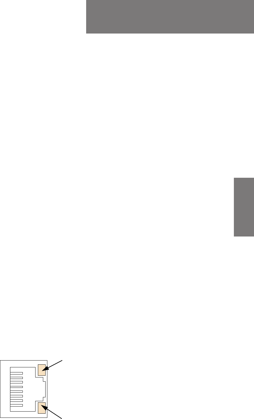
98-127093-H 4-1
Chapter 4
4444
Connectors and pin-out 4
This chapter has the following sections:
•TT-5040A SBU
•TT-5016A HLD
•TT-5622B 2-Wire Cradle
•Mating connectors in aircraft
4.1 TT-5040A SBU
The TT-5040A SBU provides interfaces for configuration, Aircraft and satcom
interconnections and for the CM.
4.1.1 Connectors on SBU
There are three connectors on the SBU:
• SBU Maintenance connector (front):
Interface to PC for configuration and maintenance purposes.
A 10/100BaseT Ethernet connector with two LED indicators, RJ45 female.
• SBU rear receptacle (top plug and bottom plug):
Interface to Aircraft and satcom interconnections.
An ARINC 404 Shell Size 2 Receptacle.
• Connector for CM (rear, inside connector):
Internal connector used only as interface to the CM.
A female 9-pin Sub-D Connector.
4.1.2 SBU Maintenance connector
Connector drawing
Figure 4-1: SBU Maintenance connector, face view of engaging end
Yellow LED
Activity
Green LED
Link
SB-Lite.book Page 1 Tuesday, September 5, 2017 1:38 PM
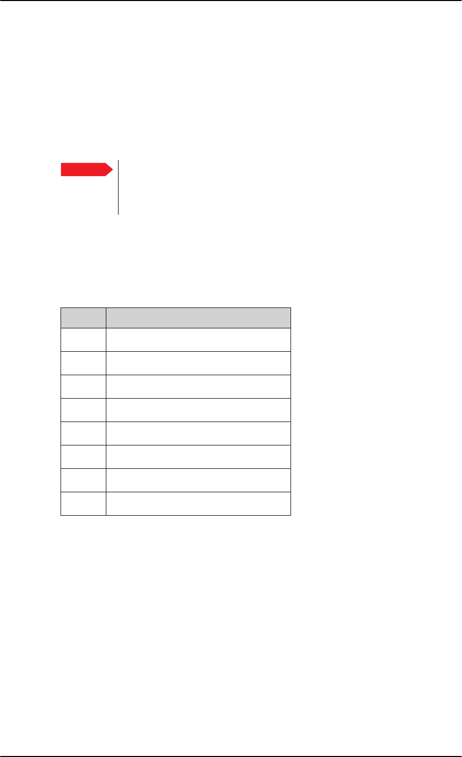
TT-5040A SBU
4-2 Chapter 4: Connectors and pin-out 98-127093-H
Connector functions
The front Maintenance interface is 10/100BaseT Ethernet, IEEE802.3.
Use this interface for the following purposes:
• AVIATOR 200/300/350 system configuration
• Maintenance
• System software upgrade
Use a standard straight network cable.
For instructions how to configure the AVIATOR 200/300/350 system see Configuration
tasks on page 6-2.
Pin-out for SBU Maintenance connector
Important For systems without the Built-in Router option enabled, i.e. the basic version
or the version with Wireless option: To use the SBU Maintenance connector
disconnect or switch off any PC connected to another LAN interface of the
SBU.
Pin no. Pin Name
FP1 TxD+ input
FP2 TxD- input
FP3 RxD+ output
FP4 Not Used
FP5 Not Used
FP6 RxD- output
FP7 Not Used
FP8 Not Used
Table 4-1: Pin-out for SBU Maintenance connector
(standard Ethernet)
SB-Lite.book Page 2 Tuesday, September 5, 2017 1:38 PM
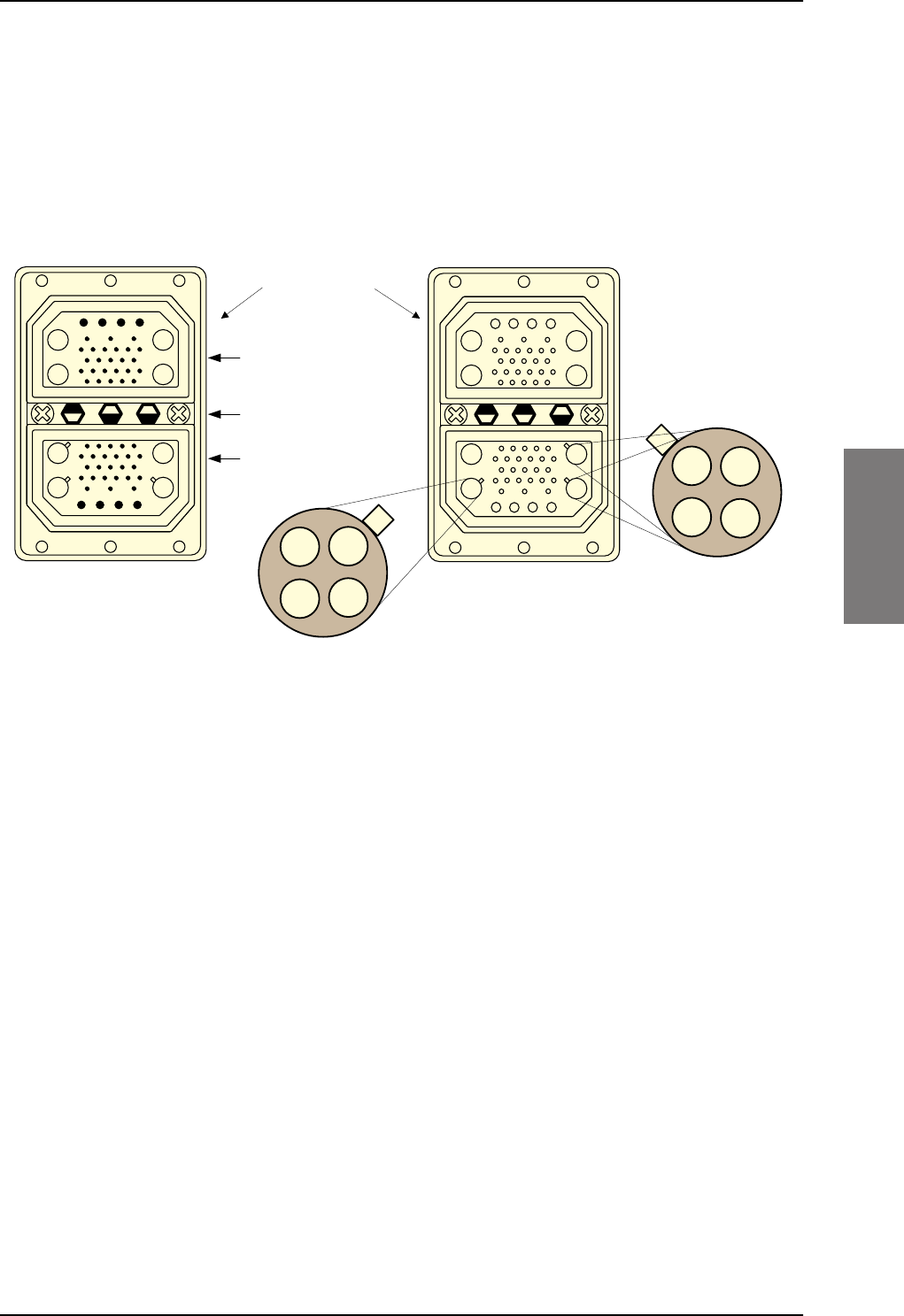
TT-5040A SBU
98-127093-H Chapter 4: Connectors and pin-out 4-3
4444
4.1.3 SBU rear receptacle
Connector drawing
The following drawing shows the SBU rear receptacle and mating plug.
Figure 4-2: SBU rear receptacle, engaging end (Index code: 19)
7RS3OXJ73,QVHUW
%RWWRP3OXJ%3,QVHUW
,QGH[3LQ&RGH
/LJKWDUHDVDUHNH\KROHV
$$
$$
$ $
$ $
$ $
$ $
$$
$$
9LHZ(QJDJLQJHQG
6%85HDU5HFHSWDFOH 0DWLQJ3OXJLQ7UD\
4XDGUD[(WKHUQHW,QVHUW
LQ$
4XDGUD[(WKHUQHW,QVHUW
LQ$DQG$
SB-Lite.book Page 3 Tuesday, September 5, 2017 1:38 PM
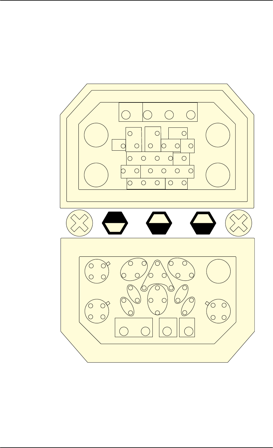
TT-5040A SBU
4-4 Chapter 4: Connectors and pin-out 98-127093-H
Connector drawing with functions
The following drawing shows the SBU rear receptacle with pin functions. For wiring details
of this interface see Electrical installation and wiring on page 5-8.
Figure 4-3: SBU rear receptacle with pin functions
$
5)5;
$
:/$1
$
5)7;
$
:/$1
$QQXQFLDWRUV ,6'1
,6'1 566%8&RQWURO
6SDUH,2
:/$1
(QDEOH
$7(
,6'15HVHUYHG
:
:
6%8
(QDEOH
6%8Q21*1'91RWXVHG
/DPSV
LQKLE
5LQJ 5LQJ
7,3 7,3
7[
5[
7[5[
6%8
$
(WKHUQHW
$
*36
$
(WKHUQHW
$
(WKHUQHW
%
$
%
$
1$9 1$9
(WKHUQHW
(WKHUQHW(WKHUQHW
&KDVVLV63$5(
,2
$QQXQFLDWRU63$5(
,2
7[
7[
5[
5[5[
5[
5[
5[
7[
7[
7[
7[
$
7[5[
5[7[
7[5[
5[7[
5[
7[
7[
5[
$
%
$
%
%68,1 %68287
7[
5[
7[5[
,Q
$
,Q
%
2XW
%
2XW
$
1RFRQQHFW
6LJQDO*1'
SB-Lite.book Page 4 Tuesday, September 5, 2017 1:38 PM

TT-5040A SBU
98-127093-H Chapter 4: Connectors and pin-out 4-5
4444
Connector functions, top plug
The top plug of the SBU rear receptacle connects the following signals:
Power & RF Interfaces:
• +28 V DC and GND, Power return
• RF Tx signal to TT-5016A HLD and Modem interface and DC power to HLD
• RF Rx signal from TT-5016A HLD
• Two RF WLAN antenna connectors (2.4 GHz)
User Interfaces:
• One ISDN, 4-wire connection
• Two analogue 2-wire standard POTS interfaces for Voice/Fax/Modem/secure voice
Control & Maintenance Interfaces:
• Discrete SBU nON input
• Discrete WLAN Enable input
• Discrete Chime/Lamps Inhibit Input
• 3 configurable Annunciators: #1 (“Incoming call”), #2 (“SBU Failed”) and #3 (“Service
Available”)
• Two ATE Discrete inputs for factory use - Do not connect
• One Discrete Spare I/O
• ISDN #2, Reserved - Do not connect
• RS-422, Reserved - Do not connect
SB-Lite.book Page 5 Tuesday, September 5, 2017 1:38 PM

TT-5040A SBU
4-6 Chapter 4: Connectors and pin-out 98-127093-H
Connector functions, bottom plug
The bottom plug of the SBU rear receptacle connects the following signals:
Power & RF Interfaces:
• GPS antenna input
• Chassis ground
User Interfaces:
• Six 10/100BaseT Ethernet
Aircraft interfaces:
• Two high or low speed ARINC 429 navigational input
• One high or low speed ARINC 429 BSU output
• One high or low speed ARINC 429 BSU input
Control & Maintenance Interfaces:
• Two Discrete Spare I/O
• One Discrete Output: Annunciator #4 (“Message received”)
SB-Lite.book Page 6 Tuesday, September 5, 2017 1:38 PM

TT-5040A SBU
98-127093-H Chapter 4: Connectors and pin-out 4-7
4444
Pin-out for SBU rear receptacle (top plug)
Table 4-2: Pin-out for SBU rear receptacle, top plug
Pin Function
TP A1 RF TX output to TT-5016A HLD, DC
output and modem interface
TP A2 WLAN antenna #2 (coax)a
TP A3 RF RX input from TT-5016A HLD
TP A4 WLAN antenna #1 (coax)a
TP1 SBU +28 V DC Power
TP2 SBU GND, Power Return
TP3 SBU nON, Discrete Input
TP4 Not used
TP5 WLAN Enable, Discrete Input
TP6 2-Wire Voice/Fax/Modem #1 (Ring)
TP7 2-Wire Voice/Fax/Modem #2 (Ring)
TP8 SBU Enable, Discrete Input (connect to
Chassis ground)
TP9 ATE #1, for factory use - Do not
connect!
TP10 ATE #2, for factory use - Do not
connect!
TP11 2-Wire Voice/Fax/Modem #1 (Tip)
TP12 2-Wire Voice/Fax/Modem #2 (Tip)
TP13 Chime/Lamps Inhibit Input, (Discrete I/O)
TP14 Spare I/O, (Discrete I/O)b
TP15 ISDN #2 Tx+ (c) output (TE)
Do not connect!
TP16 ISDN #2 Rx+ (d) input (TE)
Do not connect!
TP17 ISDN #2 Rx- (e) input (TE)
Do not connect!
TP18 ISDN #2 Tx- (f) output (TE)
Do not connect!
TP19 Output B, RS-422 Do not connect!c
TP20 Output A, RS-422 Do not connect!c
TP21 Input B, RS-422 Do not connect!c
TP22 Input A, RS-422 Do not connect!c
TP23 ISDN #1 Rx+ (c) input (NT)
TP24 ISDN #1 Tx+ (d) output (NT)
TP25 ISDN #1 Tx- (e) output (NT)
TP26 ISDN #1 Rx- (f) input (NT)
TP27 Annunciator #3, (Discrete I/O, Service
available)b
TP28 Annunciator #1, (Discrete I/O, Incoming
call)
TP29 Annunciator #2, (Discrete I/O, SBU fail)
a. Do not connect if SB-Safety voice is to be enabled.
b. This pin has an alternate function when SB-Safety
Voice is enabled, refer to Configure the discrete
I/O interfaces on page 6-37.
c. Software 2.03 and higher: Can be used for AIS 380
Aircraft Interface Module.
Pin Function
SB-Lite.book Page 7 Tuesday, September 5, 2017 1:38 PM

TT-5040A SBU
4-8 Chapter 4: Connectors and pin-out 98-127093-H
Pin-out for SBU rear receptacle (bottom plug)
Table 4-3: Pin-out for SBU rear receptacle, bottom plug
Pin no. Pin name
BP A1.1 Tx+ 10/100BaseT Ethernet #1 (Quadrax
pin 1, Input)
BP A1.2 Rx+ 10/100BaseT Ethernet #1 (Quadrax
pin 2, Output)
BP A1.3 Tx- 10/100BaseT Ethernet #1 (Quadrax
pin 3, Input)
BP A1.4 Rx- 10/100BaseT Ethernet #1 (Quadrax
pin 4, Output)
BP A2.1 Tx+ 10/100BaseT Ethernet #2 (Quadrax
pin 1, Input)
BP A2.2 Rx+ 10/100BaseT Ethernet #2 (Quadrax
pin 2, Output)
BP A2.3 Tx- 10/100BaseT Ethernet #2 (Quadrax
pin 3, Input)
BP A2.4 Rx- 10/100BaseT Ethernet #2 (Quadrax
pin 4, Output)
BP A3.1 Tx+ 10/100BaseT Ethernet #3 (Quadrax
pin 1, Input)
BP A3.2 Rx+ 10/100BaseT Ethernet #3 (Quadrax
pin 2, Output)
BP A3.3 Tx- 10/100BaseT Ethernet #3 (Quadrax
pin 3, Input)
BP A3.4 Rx- 10/100BaseT Ethernet #3 (Quadrax
pin 4, Output)
BP A4 GPS antenna input (coax), Modem,
DC out
BP1 Annunciator #4 (Discrete I/O, Message
received)
BP2 Spare I/O, (Discrete I/O)a
BP3 SBU Chassis Ground
BP4 Spare I/O, (Discrete I/O)a
BP5 Data from primary ARINC429
navigational input, A
BP6 Rx- 10/100BaseT Ethernet #4, (Output)
BP7 Data from secondary ARINC429
navigational input, A
BP8 Data from primary ARINC429
navigational input, B
BP9 Data from BSU or CMU, ARINC 429 A
BP10 Tx+ 10/100BaseT Ethernet #4, (Input)
BP11 Tx- 10/100BaseT Ethernet #4, (Input)
BP12 Data to BSU or CMU, ARINC 429 A
BP13 Data from secondary ARINC429
navigational input, B
BP14 Data from BSU or CMU, ARINC 429 B
BP15 Common Signal GND for Ethernet
BP16 Rx+ 10/100BaseT Ethernet #4, (Output)
BP17 Common Signal GND for Ethernet
BP18 Data to BSU or CMU, ARINC 429 B
BP19 Rx- 10/100BaseT Ethernet #5, (Output)
BP20 Tx- 10/100BaseT Ethernet #5, (Input)
BP21 Common Signal GND for Ethernet
BP22 Common Signal GND for Ethernet
BP23 Rx- 10/100BaseT Ethernet #6, (Output)
BP24 Tx- 10/100BaseT Ethernet #6, (Input)
BP25 Tx+ 10/100BaseT Ethernet #5, (Input)
BP26 Rx+ 10/100BaseT Ethernet #5, (Output)
BP27 Common Signal GND for Ethernet
BP28 Tx+ 10/100BaseT Ethernet #6, (Input)
BP29 Rx+ 10/100BaseT Ethernet #6, (Output)
a. This pin has an alternate function when SB-Safety
Voice is enabled, refer to Configure the discrete
I/O interfaces on page 6-37.
Pin no. Pin name
SB-Lite.book Page 8 Tuesday, September 5, 2017 1:38 PM
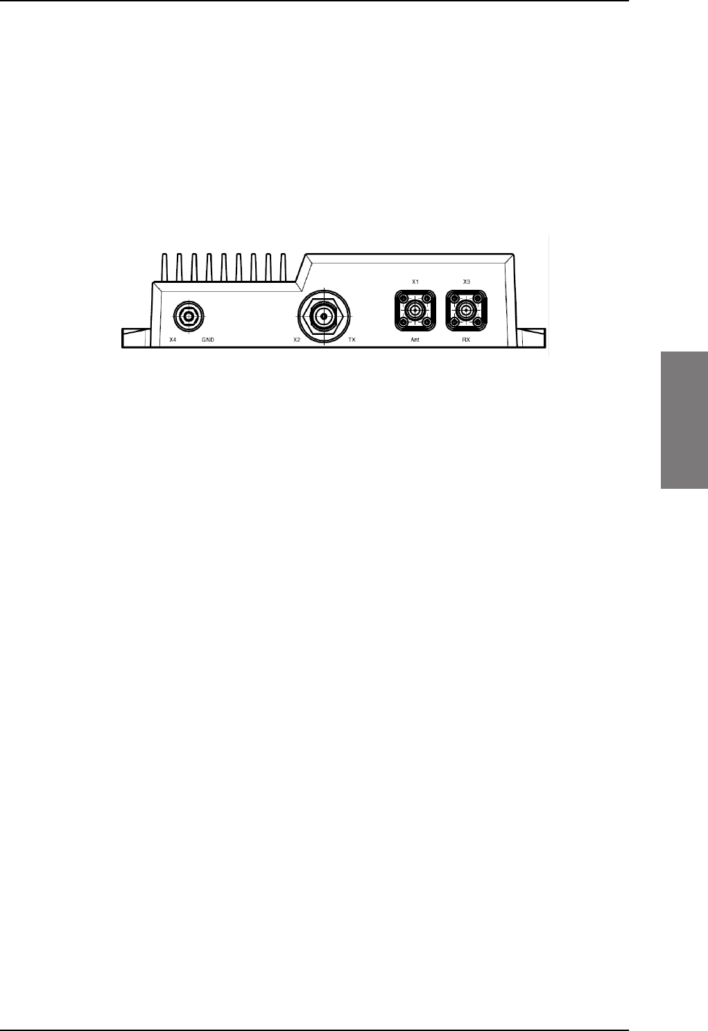
TT-5016A HLD
98-127093-H Chapter 4: Connectors and pin-out 4-9
4444
4.2 TT-5016A HLD
The HLD is installed between the SBU and the satcom antenna.
4.2.1 Connectors on HLD
Connector drawing
Figure 4-4: TT-5016A HLD connector panel
Connector functions
There are three connectors and a Ground stud on the HLD:
• X1: Antenna connector for L-Band Rx/Tx interface to the satcom antenna,
TNC-female.
• X2: Tx connector for L-Band Tx interface, modem interface and 28 V DC from the SBU
N-female
• X3: Rx connector for L-Band Rx interface to the SBU,
TNC-female
• X4: Chassis Ground stud for connecting the HLD chassis to the aircraft chassis.
SB-Lite.book Page 9 Tuesday, September 5, 2017 1:38 PM
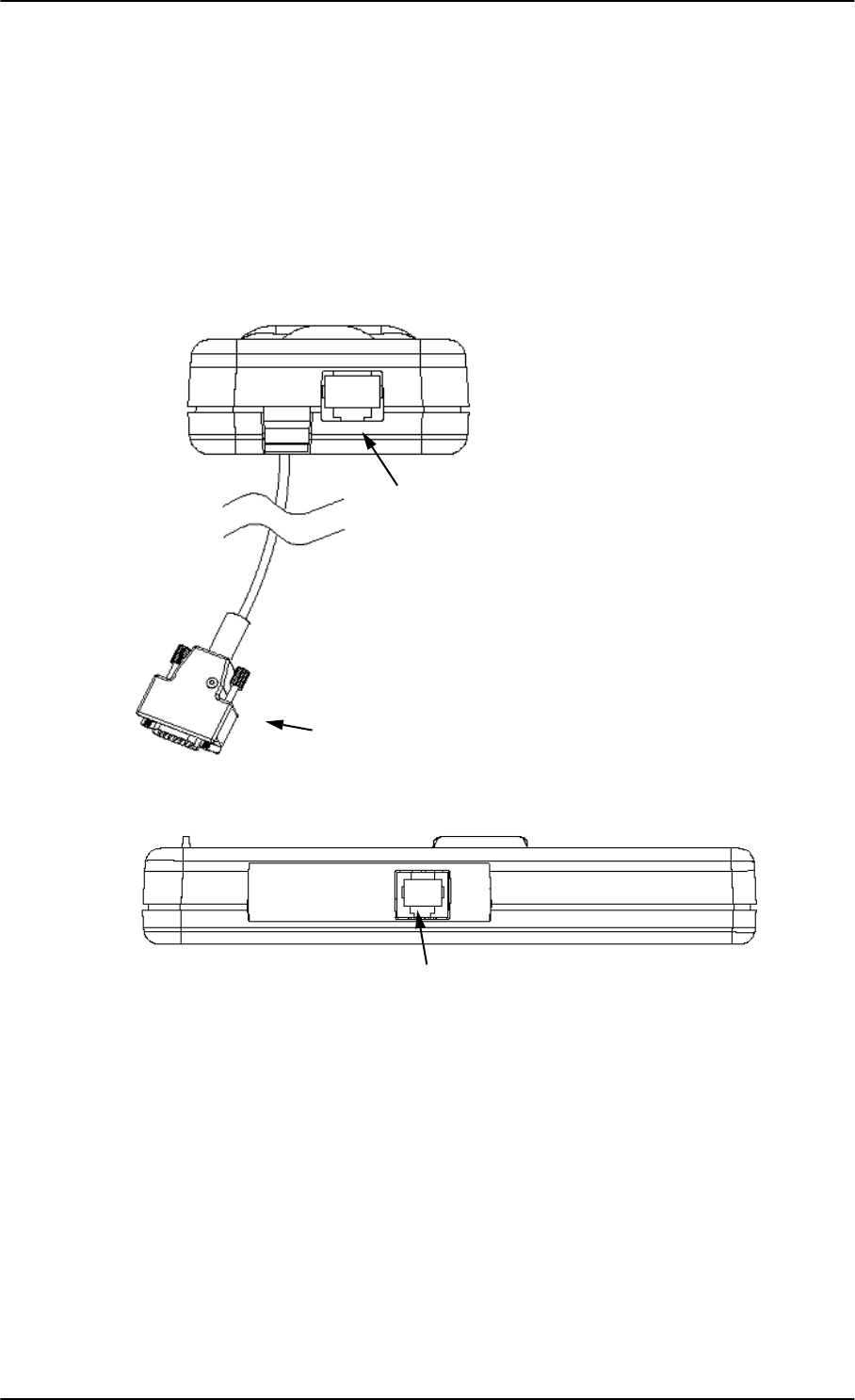
TT-5622B 2-Wire Cradle
4-10 Chapter 4: Connectors and pin-out 98-127093-H
4.3 TT-5622B 2-Wire Cradle
The TT-5622B 2-Wire Cradle provides the analogue 2-wire standard POTS interface for
Voice/Fax/Modem/secure voice and serves as a holder for the 2-Wire Handset.
4.3.1 Connectors on 2-Wire Cradle
There are three connectors on the 2-Wire Cradle, one at the side and two at the end:
Figure 4-5: 2-Wire Cradle connectors, end view of cradle
Figure 4-6: TT-5622B 2-Wire Cradle connectors, side view of cradle
2-Wire Handset connection
SBU connection
2-Wire Voice/Fax/Modem/secure voice connection
SB-Lite.book Page 10 Tuesday, September 5, 2017 1:38 PM
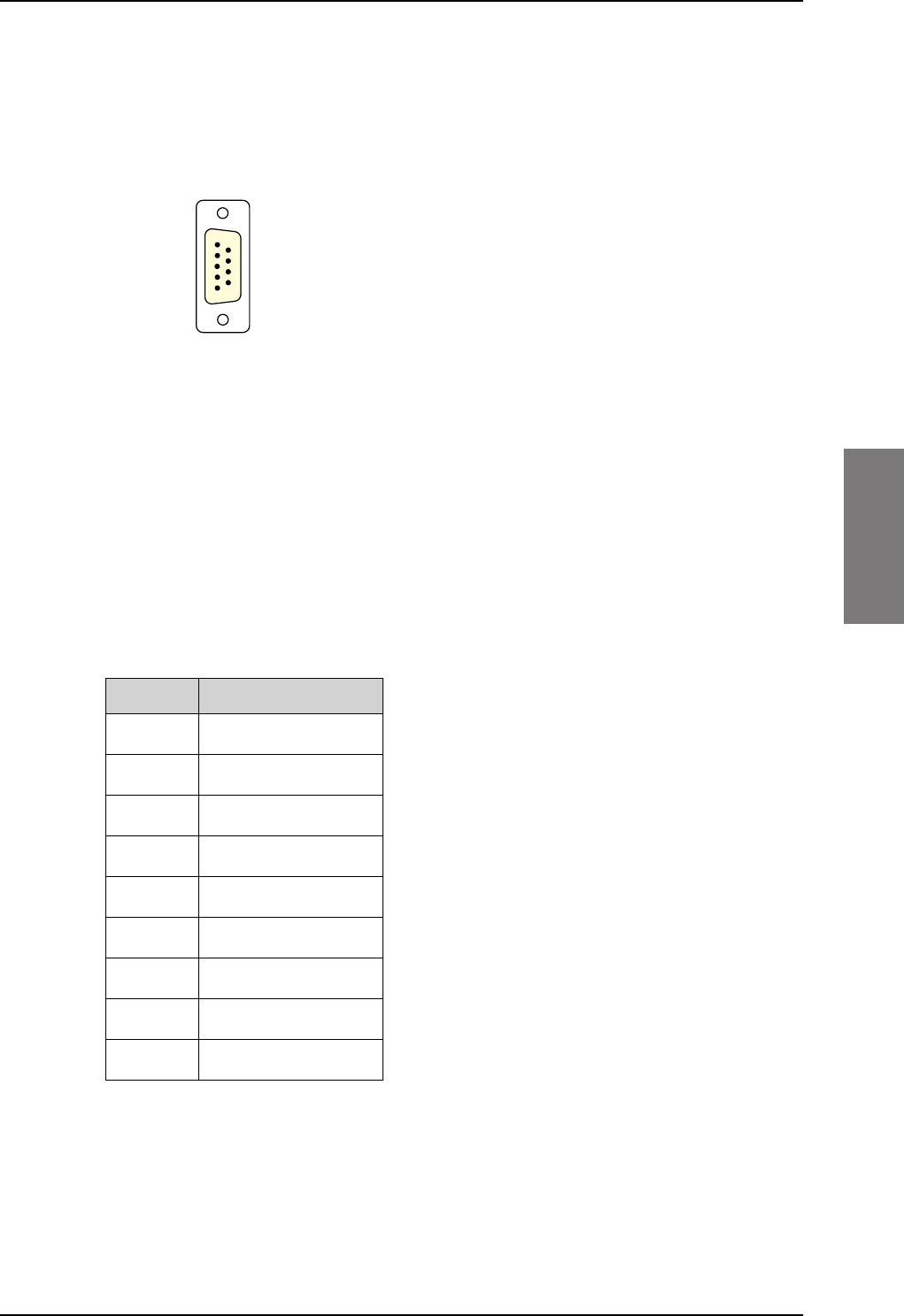
TT-5622B 2-Wire Cradle
98-127093-H Chapter 4: Connectors and pin-out 4-11
4444
4.3.2 2-Wire Cradle connector to SBU
Connector drawing
Connector functions
The 9 pin Sub-D male connector on the short cable at the end of the 2-Wire Cradle
connects the following signals on the SBU:
• Analogue 2-wire standard POTS interface for Voice/Fax/Modem/secure voice.
Pin-out for 2-Wire Cradle connector to SBU
The 2-Wire Cradle connector to connect to the SBU has the following pin-out:
The other two connectors are standard POTS RJ11 connectors.
Figure 4-7: 2-Wire Cradle connector
(DB9M). View: Solder side
9LHZ6ROGHUVLGH
'%0DOH
Pin Function
1 Auxiliary Tip
2 Auxiliary Ring
3 Shield
4 Not connected
5 Not connected
6 Not connected
7 Not connected
8 Not connected
9 Not connected
Table 4-4: Pin-out for 9 pin Sub-D male
connector in TT-5622B 2-Wire Cradle
SB-Lite.book Page 11 Tuesday, September 5, 2017 1:38 PM

Mating connectors in aircraft
4-12 Chapter 4: Connectors and pin-out 98-127093-H
4.4 Mating connectors in aircraft
4.4.1 Connection with SBU
Note that the SBU tray holds the mating connector for the SBU rear connector.
Table 4-5: Mating connectors in aircraft for SBU
SBU Maintenance connector
(on front panel)
RJ45 male
SBU rear receptacle
(rear connector in the SBU
tray)
ARINC 404 shell size 2 plug with the following contact
arrangements:
Insert A (Top Plug): 33C4
• 4 #16 socket contacts
• 25 #20 socket contacts
• 4 #5 coax sockets
Insert B (Bottom Plug): 33C4
• 4 #16 socket contacts
• 25 #20 socket contacts
• 1 #5 coax sockets
• 3 #5 quadrax sockets
Part number: DPX2NA-67322-606
Size 5 coax contacts fit for cable type RG-142. For other cable types you must order
suitable contact inserts. For part numbers see Table 5-32 on page 5-48 and Table 5-33 on
page 5-49.
Connector Mating connector type
SB-Lite.book Page 12 Tuesday, September 5, 2017 1:38 PM

98-127093-H 5-1
Chapter 5
5555
Installation 5
This chapter has the following sections:
•General installation information
•Mounting considerations
•Electrical installation and wiring
•Recommended cables
•Activation of airtime services
5.1 General installation information
5.1.1 Overview
This chapter contains considerations and recommendations for installation of the
AVIATOR 200/300/350 System. Interconnect harness wiring and physical mounting must
satisfy all applicable regulations.
For installation kits for the AVIATOR 200/300/350 system contact:
Table 5-1: Installation kits, contact information
The information, drawings and wiring diagrams contained in this manual are intended as a
reference for engineering planning only. The drawings and wiring diagrams contained
herein do not represent any specific STC. It is the installer’s responsibility to compose
installation drawings specific to the aircraft. This manual and the drawings and wiring
diagrams contained herein may not be used as a substitute for an STC.
To ensure optimal performance from the AVIATOR 200/300/350 system, you
must maintain strict adherence to the installation guidelines in this chapter.
Note Installation kits including wiring can be obtained through ECS (Electronic Cable
Specialists, Inc.) or EMTEQ Inc. For details and order numbers see Installation kits
on page 2-12.
ECS, a Carlisle IT company, USA
Phone (Franklin, WI): +1 800-327-9473
Phone (Kent, WA): +1 800-227-5953
E-mail: sales@CarlisleIT.com
Home page: www.CarlisleIT.com
EMTEQ (B/E Aerospace)
Home page: www.emteq.com
Contact info: www.emteq.com/contact-us.php
Note
SB-Lite.book Page 1 Tuesday, September 5, 2017 1:38 PM
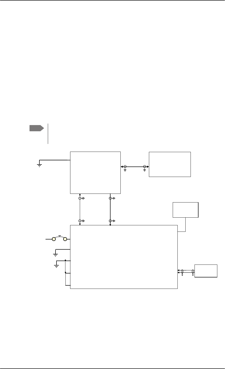
General installation information
5-2 Chapter 5: Installation 98-127093-H
5.1.2 Minimum system components
A minimum working system has at least:
• one TT-5040A SBU
• one TT-5040A-001 CM
• one TT-5016A HLD
• one satcom antenna, LGA, IGA, or HGA antenna, see also Satcom antenna systems on
page 2-4.
The CM, HLD and some satcom antennas are powered by the SBU. The following drawing
shows the minimum installation.
Minimum system drawing
This drawing is an overview of which units to connect as a minimum.
For information on other satcom antenna types supported and wiring of the
individual antenna types, refer to the appropriate section of Electrical installation
and wiring on page 5-8 and onwards.
Figure 5-1: AVIATOR 200 minimum system (example with LGA TT-3002A and GPS antenna)
For other navigational input sources see Table 5-2 on page 5-4.
Note
77$
6%8
77$
+/'
73$
73$
;
;
;
%3$
*36LQ
'&RXW
: :
:
; 77$
$QWHQQD
/RVV
G%#0+]
/RVV
G%#0+]
/RVV
G%#0+]
G%#0+]
'&UHVLVWDQFHȍ
5)5[
5)7[
'&3RZHU
0RGHP
&KDVVLV*URXQG
5)5[7[
5)5[
*36$QWHQQD
9'&
$LUFUDIW
3RZHU6XSSO\
,56$+56$$%3
,56$+56$%%3
,5613,*166
RSWLRQDO
73*1'3RZHU5HWXUQ
739'&3RZHU
%3&KDVVLV*URXQG
735HPRWHRQRIIQ21
736%8(QDEOH
SB-Lite.book Page 2 Tuesday, September 5, 2017 1:38 PM

Mounting considerations
98-127093-H Chapter 5: Installation 5-3
5555
5.2 Mounting considerations
5.2.1 Overview
For optimum system performance, some guidelines on where to install or mount the
components of the AVIATOR 200/300/350 system must be followed. Mounting and
placement details are included in this section.
For information on requirements to cables, see the individual sections in Electrical
installation and wiring on page 5-8. For information on recommended cable types and
lengths, see Recommended cables on page 5-47.
5.2.2 TT-5040A SBU
Forced cooling is not required and not recommended.
• Install the SBU in temperature controlled areas and inside or outside pressurized
locations (e.g. avionics bay).
• Mount the SBU in an ARINC 404A 1/4 ATR short tray as shown in Figure 3-9: Outline
drawing: SBU tray: ECS PO299-101 or see SBU trays on page 3-10 for allowed SBU
trays.
5.2.3 TT-5016A HLD
Forced cooling is not required for the HLD.
• Install the HLD in non-temperature controlled locations and inside or outside
pressurized locations.
• Make sure the cable loss requirements are met, for further details see Recommended
cables on page 5-47.
• Place the HLD with sufficient contact to the mounting surface for proper grounding,
respecting the maximum cable resistance. The HLD can be mounted on a shelf or
directly on the fuselage.
• Ground the HLD through the 4 threaded mounting holes or by using the ground stud.
The HLD can heat up to 20 degrees above ambient temperature after a long period
of intense use. To avoid internal overheating the HLD automatically reduces
activity. Place the HLD with as much free space around it as possible to keep the
temperature down and optimize performance.
• Place the HLD unit close to the top-mounted satcom antenna to minimize the cable
length. Place the HLD preferably between the fuselage ribs in the cabin ceiling. In this
location there may be a risk for reduced heat dissipation, so make sure that the HLD can
dissipate the heat to the aircraft structure.
For aircraft with very little ceiling space you may install the HLD unit in the rear avionics
bay, the luggage compartment or other suitable locations inside or outside of pressurized
areas.
Note When mounting the units, allow enough space to provide a sufficient bend radius
for the cables. See the cable data sheet for minimum bend radius.
Note
SB-Lite.book Page 3 Tuesday, September 5, 2017 1:38 PM

Mounting considerations
5-4 Chapter 5: Installation 98-127093-H
5.2.4 Satcom antenna
In order to steer the satcom antenna towards the satellite, the AVIATOR 200/300/350
system needs to know the position and attitude of the aircraft. Several methods are
available to achieve this.
The following table gives an overview of the supported navigational input sources for the
different satcom antenna types.
Table 5-2: Navigational input for satcom antennas
Satcom antenna type
Navigational input
IRS
(A429)
AHRS + GPS
(A429+coax)
NRS
(coax)
NPI
(A429)
GNSS
(A429)
GPS only
(coax)
TT-3002A LGA/LGA-3000 X X X X
TT-5006A IGA X X X
IGA-5001 X X
AMT-3500 X X
HGA-6000/HGA-6500 X X
HGA-7000/HGA-7001 X X
AMT-50/700/3800 X X
CMA-2102/CMA-2102SB X X
About satcom antenna steering for IGA and HGA (AVIATOR 300 and AVIATOR 350)
•IRS: If IRS is used, the antenna positioning data is computed from the IRS data alone.
All necessary data is available from the IRS.
•AHRS + GPS: AHRS does not include all the necessary data, therefore a GPS RF signal
must be sent to the SBU. A GPS module is built into the SBU, it computes the necessary
position and speed information.
In case the TT-5006A IGA is used, a GPS antenna is built into the antenna, and the GPS-
RF is fed to the SBU.
If another satcom antenna is used, e.g. a HGA, the GPS RF signal may be obtained from
a GPS antenna already installed on the aircraft.
The GPS RF signal enters the SBU at the SBU rear receptacle (bottom plug) BPA4 GPS
antenna input.
•NRS: A special way to steer the antenna, without the need for on-board IRS/AHRS
systems, is to use the NRS system. This is ONLY possible with the TT-5006A antenna.
The NRS system consists of two parts: a 3-D magnetometer built in to the TT-5006A,
and a GPS module built into the SBU. The 3-D magnetometer in the antenna senses the
magnitude and direction of the magnetic field. This information is sent to the SBU,
where it is compared to the expected magnetic vector at the current position received
from the GPS. The expected magnetic vector is obtained from a mathematical model of
Earth’s magnetic field, and the knowledge of the current position, calculated in the GPS
module. In this way the system can calculate the attitude of the aircraft.
SB-Lite.book Page 4 Tuesday, September 5, 2017 1:38 PM

Mounting considerations
98-127093-H Chapter 5: Installation 5-5
5555
The advantage of this system is that it is stand-alone and does not require any
interaction with other avionics systems. The disadvantage is that it requires a fairly
clean magnetic environment, where the antenna is placed. There may not be any
magnetic items such as screws, loudspeakers or DC cables near the antenna. See also
Magnetic interference considerations (only for TT-5006A IGA) on page 5-6.
Position and velocity information for LGA (AVIATOR 200)
The position and velocity information is used for spot-beam selection and Doppler
compensation. The following navigational inputs can only be used together with the TT-
3002A low-gain antenna, where attitude data are not required:
•GPS only: The built-in GPS receiver provides all the necessary navigation data if the
SBU receives an RF signal from a GPS antenna on the pin BP A4 of the SBU rear
receptacle, bottom plug (see Table 4-3 on page 4-8).
•NPI: NPI (Navigation Position Information, a Thrane abbreviation) is similar to IRS but
there is no requirement for attitude information. The navigation data can be obtained
from other sources than an IRS. Note that the navigation data must be coded exactly as
for IRS. For detailed information see Table 5-13 on page 5-27.
•GNSS can be used together with the TT-3002A low-gain antenna. Since this antenna
does not have any antenna steering mechanisms that must be controlled, the GNSS can
provide all necessary navigational data. GNSS is compliant with ARINC-743A [14]. For
detailed information see Table 5-14 on page 5-27.
Satcom antenna types supported
For a list of Cobham SATCOM antenna types supported in the AVIATOR 200/300/350
system see Satcom antenna systems on page 2-4.
General mounting considerations
Refer to the satcom antenna manual for instructions and details on mounting the antenna.
Make sure all requirements in the antenna mounting instructions are met.
Place the antenna with unobstructed view to the satellite.
Note If possible, always use IRS or AHRS. IRS and AHRS give better precision. Only
use NRS as a last option.
WARNING! Keep a safety distance of minimum 30 cm (1 ft) for LGA and
IGA and 90 cm (3 ft) for HGA to the antenna when the system is transmitting,
unless the antenna manual or the specific system configuration presents
different requirements. This safety distance ensures that a maximum radiation
power density of maximum 10 W/m2 is not exceeded (Recommended by the
American National Standards Institute, ANSI/LEEE C95.1-1992).
Note The antenna installation must be in accordance with the aircraft manufacturers
requirements and/or FAA AC 43.13 - 1B/2A and approved by the appropriate Civil
Aviation Authorities.
SB-Lite.book Page 5 Tuesday, September 5, 2017 1:38 PM

Mounting considerations
5-6 Chapter 5: Installation 98-127093-H
Magnetic interference considerations (only for TT-5006A IGA)
You may use the NRS antenna steering system if the TT-5006A IGA is mounted on the
aircraft in an area free of magnetic interference.
The following paragraphs are only applicable if you use NRS functionality.
The TT-5006A IGA contains sensitive magnetometers. These can be adversely influenced
by ferrous materials, magnets or large currents in cables close to the antenna. Therefore
you must obey the following mounting considerations.
• Do not mount speakers or other equipment containing a magnet within 48 cm
(18 inches) of this satcom antenna. If this cannot be avoided, install shielded speakers.
• Avoid mounting close to strong magnetic fields from the aircraft’s power wiring (DC
cables).
• Use non-magnetic screws and tools for mounting.
Distance between GPS antenna and satcom antenna
Make sure the GPS antenna is installed with sufficient distance to the satcom antenna. For
requirements to the radiation distance, refer to the manual for the GPS system.
However, always keep the following distances between the satcom antenna
and the GPS antenna:
– Minimum 30 cm (11.8 inches) for LGA and IGA
– Minimum 50 cm (19.7 inches) for HGA
If the existing GPS antenna on board the aircraft does not provide sufficient filtering of the
satcom antenna signal to give a usable GPS signal, you must replace the existing GPS
antenna with a GPS antenna that has a satcom filter.
Distance between Glonass antenna and satcom antenna
Make sure your Glonass antenna is installed with sufficient distance to the satcom antenna.
For requirements to the radiation distance, refer to the manual for the Glonass system.
However, always keep the following distances between the satcom antenna
and the Glonass antenna:
– Minimum 120 cm (47.2 inches) for LGA and IGA
– Minimum 210 cm (82.7 inches) for HGA
If the existing Glonass antenna on board the aircraft does not provide sufficient filtering of
the satcom antenna signal to give a usable Glonass signal, you must replace the existing
Glonass antenna with a Glonass antenna that has a satcom filter.
Cables between TT-5016A HLD and satcom antenna
We recommend to keep the cable length as short as possible.
Do not bend the cables to a radius smaller than the minimum bend radius stated for the
cables. For further information on cables, see Wiring the satcom antenna on page 5-10 and
Recommended cables on page 5-47.
Note
Important
Important
SB-Lite.book Page 6 Tuesday, September 5, 2017 1:38 PM

Mounting considerations
98-127093-H Chapter 5: Installation 5-7
5555
5.2.5 TT-5040A-004 WLAN antennas
The recommended WLAN antenna to use with the AVIATOR 200/300/350 system is the
TT5040A-004 Wireless Antenna. The WLAN antenna is PMA approved by VT Miltope (P/N
901167-2). You may also use other WLAN antennas approved for aeronautical use.
Cobham SATCOM recommends to use 2 WLAN antennas to get optimum
performance on board.
1. Mount the WLAN-antennas in the aircraft cabin. Install the 2 WLAN antennas in the
same plane (surface).
2. Install the two WLAN antennas with a distance of minimum 12.5 cm (5 inches)
between the two antennas.
3. For optimum performance mount the two antennas at an angle of 90° to each other.
:/$1DQWHQQD
:/$1DQWHQQD
0LQLPXPGLVWDQFH
FPLQFKHV
Figure 5-2: Mounting two WLAN antennas for optimum performance
Make sure the cable loss requirements are met, for further details see in the section Wiring
WLAN antenna interface on page 5-34.
Operating with one WLAN antenna
You can also use a single WLAN antenna. For details how to wire a single WLAN antenna see
Wiring WLAN antenna interface on page 5-34.
Note
SB-Lite.book Page 7 Tuesday, September 5, 2017 1:38 PM

Electrical installation and wiring
5-8 Chapter 5: Installation 98-127093-H
5.3 Electrical installation and wiring
5.3.1 Wiring symbols
Throughout the wiring section these common symbols are used:
The following subsections are available:
•Wiring power supply
•Wiring the satcom antenna
•Wiring ARINC 429 interfaces
•Wiring GPS interface
•Wiring Ethernet
•Wiring WLAN antenna interface
•Wiring ISDN
•Wiring telephone systems
•Wiring Sigma7 (2-wire) handsets
•Wiring ICG DECT Cordless Handset (2-wire) phone
•Wiring discretes
•Wiring the Switch Annunciator Panel
•Wiring the Switch Annunciator Panel
•Wiring the maintenance interface
Coax
Shield
Ground (fuselage)
Twisted
Twisted and shielded
Table 5-3: Wiring symbols
Important Each wiring drawing in this chapter only shows the connections referred to in
that particular section. Other connections may be required for the system to
work properly.
SB-Lite.book Page 8 Tuesday, September 5, 2017 1:38 PM
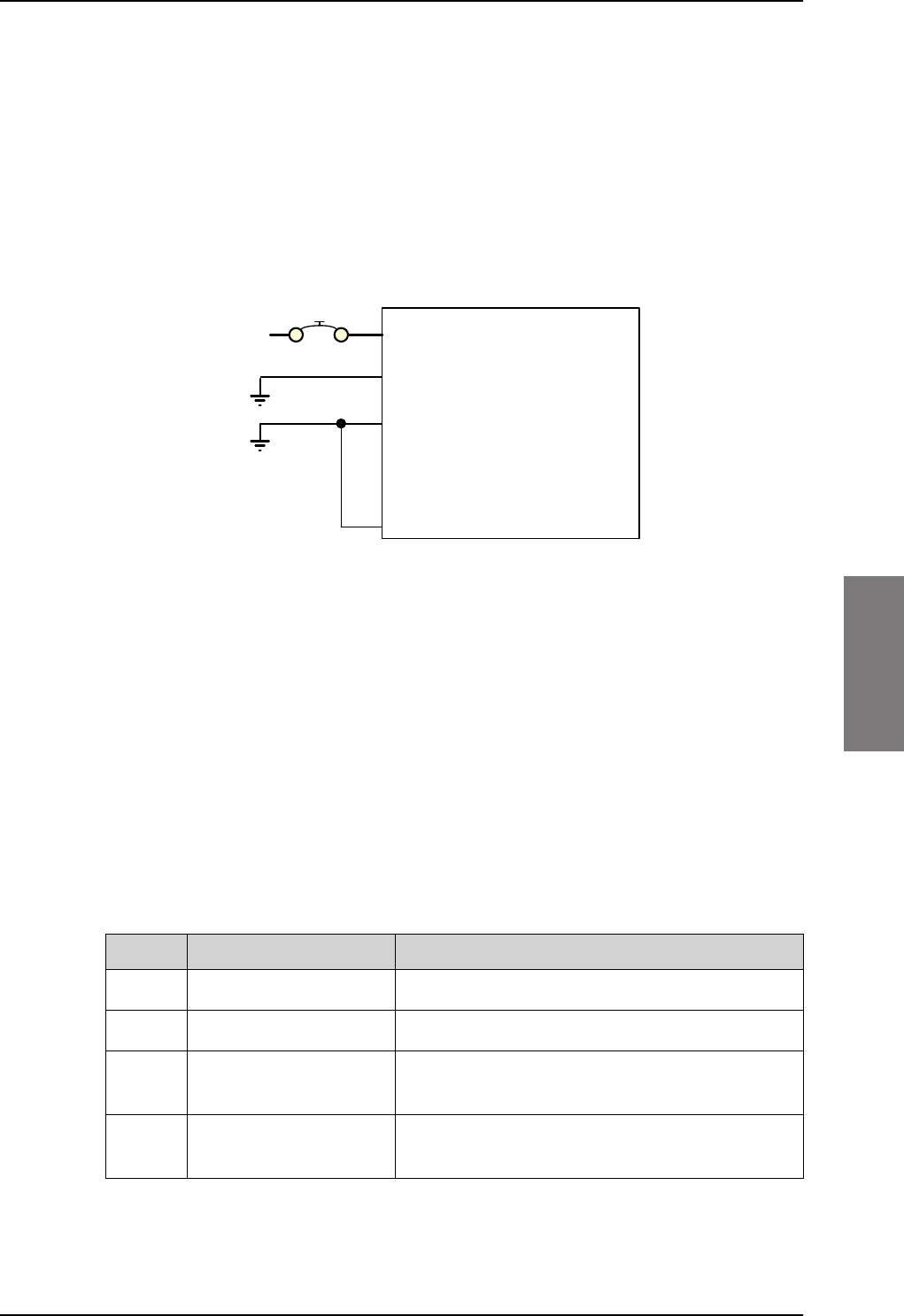
Electrical installation and wiring
98-127093-H Chapter 5: Installation 5-9
5555
5.3.2 Wiring power supply
Wiring the TT-5040A SBU
The Aircraft power bus interfaces supply the electric power required to operate the SBU.
They also supply a chassis connection to the aircraft chassis and the installation tray for
EMC purposes. The +28
V DC Power wire must include a circuit breaker capable of carrying
the required current continuously under the required environmental conditions.
The following drawing shows the wiring of the SBU to the Aircraft Power Bus.
SBU maximum power consumption
The CM, HLD and some satcom antennas are powered by the SBU. Therefore the total
power consumption of the SBU depends on which satcom antenna type is connected to
the SBU. See Table A-1 on page A-2 for the total power consumption of the SBU for the
satcom antenna types available.
Pins for SBU power supply
The following list shows the pins used for the SBU power supply.
Figure 5-3: Wiring SBU power supply
77$
6%8
>@ 73*1'3RZHU5HWXUQ
9'&
$LUFUDIW3RZHU%XV
>@7RWDOUHVLVWDQFHPD[P2KPLQFO&LUFXLW%UHDNHU
>@'LUHFWO\WR$LUFUDIW*URXQGZLWKOHVVWKDQPFDEOH7RWDOUHVLVWDQFHPD[P2KP
>@'LUHFWO\WRLQVWDOODWLRQWUD\DQGDLUFUDIWFKDVVLVPD[P2KPUHVLVWDQFH
>@5HFRPPHQGHGFLUFXLWEUHDNHU.OL[RQ7&VHULHV$FXUUHQWUDWLQJ
>@,I6$7&202Q2IIVZLWFKLVUHTXLUHG73LVURXWHGWRDQH[WHUQDOVZLWFKWRJURXQG
%3
739'&3RZHU
&KDVVLV*URXQG
>@
$
>@
>@
73 6%8Q21212))
>@
SBU pin Name Description
TP1 +28 V DC Power +28 V DC Power input from Aircraft power bus.
TP2 GND, Power Return Aircraft Ground connection
BP3 Chassis Ground Chassis connection, connected to installation tray
and Aircraft chassis.
TP3 SBU nOn, Discrete Input Power On/Off for the SBU and units powered by the
SBU
Table 5-4: Pins for SBU power supply
SB-Lite.book Page 9 Tuesday, September 5, 2017 1:38 PM
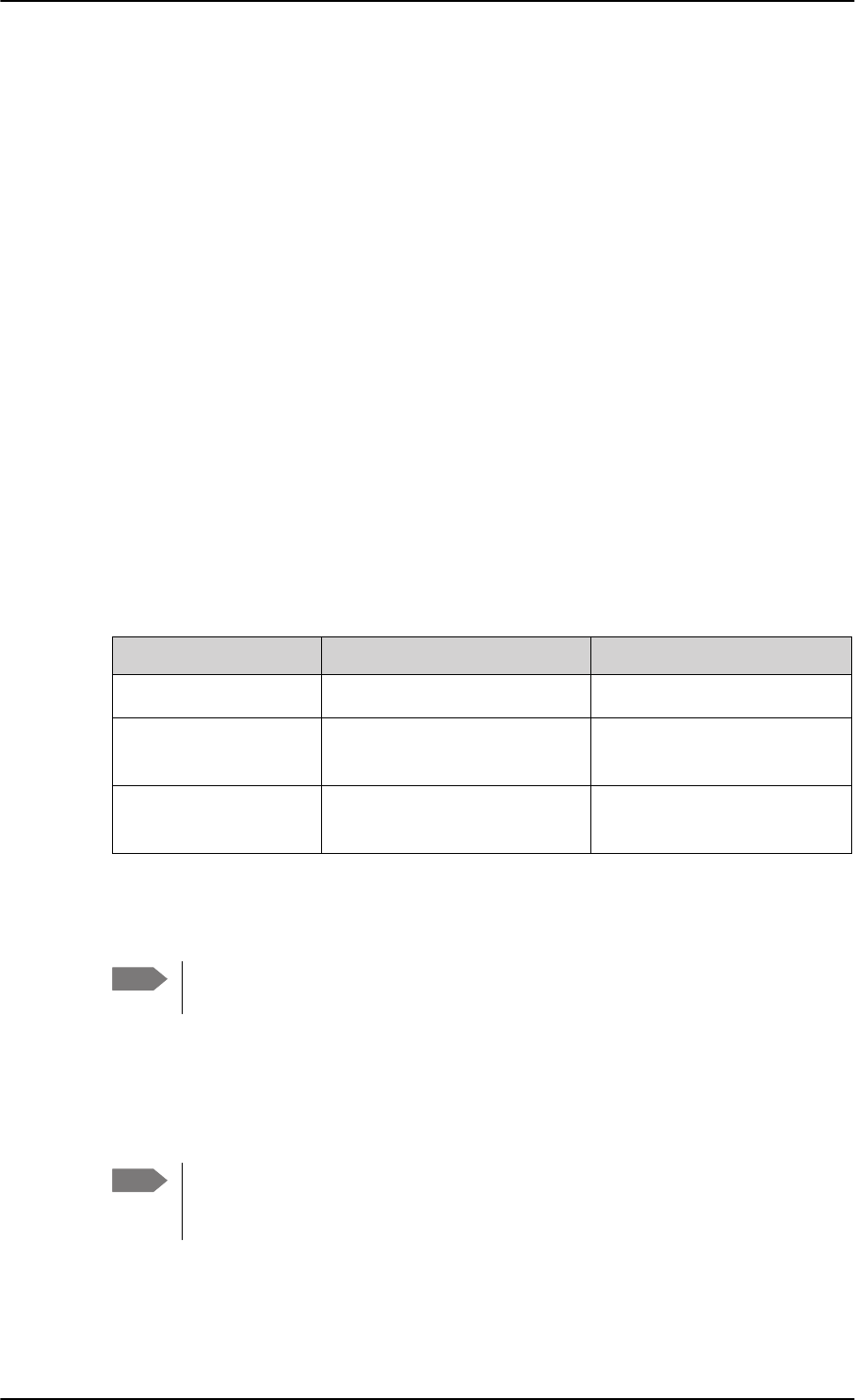
Electrical installation and wiring
5-10 Chapter 5: Installation 98-127093-H
Description of SBU power supply
+28 V DC Power
It is essential to keep the line impedance below the specified limits. See Cable
requirements, SBU power supply on page 5-10.
Reverse polarity protection is only guaranteed if the suggested circuit breaker is used. A
suitable circuit breaker with sufficiently low resistance would be Klixon 2TC series with
7.5
A current rating.
Chassis Ground (BP3)
The Chassis connection ensures that the SBU cabinet and the installation tray have the
same potential, and that there is a connection from the cable shields to the cabinet to
comply with EMC requirements.
Connect the wire directly to the installation tray and to aircraft chassis.
Remote ON/OFF - SBU nON, Discrete Input (TP3)
The nON input is used to turn the SBU on and off. Connection of this input to ground turns
on the SBU and all units powered by the SBU.
The electrical specifications are defined in Description of the discrete types on page 5-44.
Cable requirements, SBU power supply
5.3.3 Wiring the satcom antenna
Cable losses
Cablea
a. The cable numbers refer to the numbers stated on the wiring drawing in the section Figure
5-3: Wiring SBU power supply.
Max. resistance Other requirements
[1] (+28 V DC Power) 250 m, incl. circuit breaker
[2] (GND, Power Return) 25 mThe cable should be as short
as possible, max. 1 m.
[3] (Chassis Ground) 25 mConnect directly to aircraft
chassis.
Table 5-5: Requirements to SBU power cables
Note For maximum allowed cable lengths, see Power cables, allowed cable lengths on
page 5-47.
Note During installation, measure and write down the cable loss of the RF cables. You
need these values later on in the web interface during configuration of the system.
For further details see Configure RF settings on page 6-43.
SB-Lite.book Page 10 Tuesday, September 5, 2017 1:38 PM
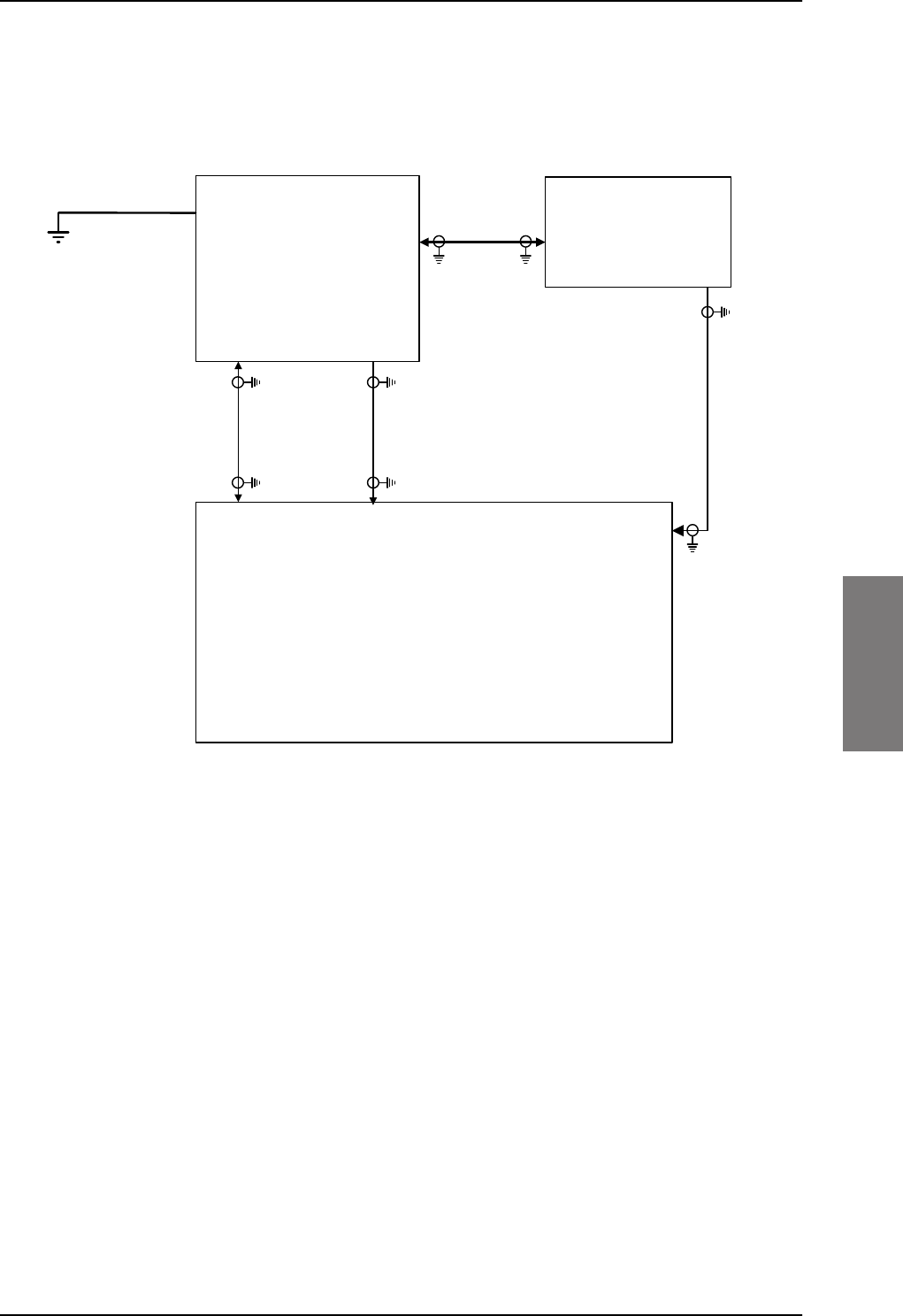
Electrical installation and wiring
98-127093-H Chapter 5: Installation 5-11
5555
Wiring TT-3002A LGA/LGA-3000
The following drawing shows the wiring for an AVIATOR 200 system using a TT-3002A low
gain antenna.
For the requirements to RF cables W1, W2 and W3 see Table 5-8 on page 5-23.
Figure 5-4: Wiring TT-3002A LGA/LGA-3000
77$
6%8
77$
+/'
73$
73$
;
;
;
%3$
*36LQ
'&RXW
: :
:
;
77$
/*$
$QWHQQD
/RVV
G%#0+]
/RVV
G%#0+]
/RVV
G%#0+]
G%#0+]
'&UHVLVWDQFHȍ
5)7[
'&3RZHU
0RGHP
5)5[
5)7[
'&3RZHU
0RGHP
&KDVVLV*URXQG
5)5[7[
5)5[
:
/RVV
G%#0+]
>@*36RQO\DYDLODEOHRQ/*$
>@
SB-Lite.book Page 11 Tuesday, September 5, 2017 1:38 PM
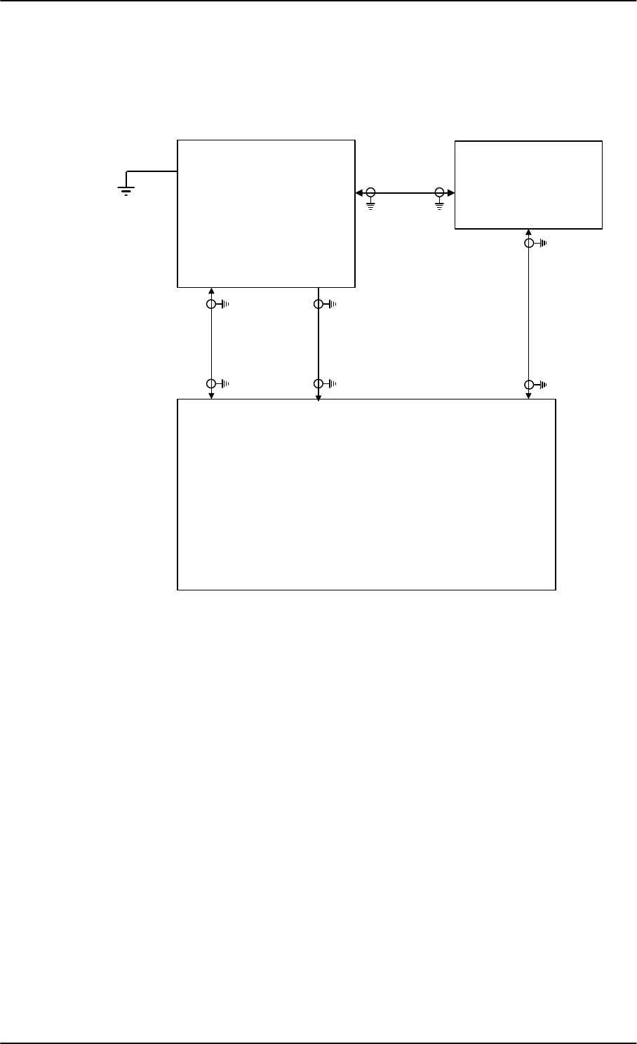
Electrical installation and wiring
5-12 Chapter 5: Installation 98-127093-H
Wiring TT-5006A IGA/IGA-5001
The following drawing shows the wiring for an AVIATOR 300 system using a TT-5006A or
IGA-5001intermediate gain antenna.
For the requirements to RF cables W1, W2 and W3 see Table 5-8 on page 5-23.
Figure 5-5: Wiring TT-5006A IGA or IGA-5001
77$
6%8
77$
+/'
73$
73$
;
;
;
%3$
*36LQ
'&RXW
$QWPRGHP
: :
:
:
;
77$
,*$
$QWHQQD
-EOXH
-UHG
/RVV
G%#0+]
/RVV
G%#0+]
/RVV
G%#0+]
G%#0+]
'&UHVLVWDQFHȍ
/RVV
G%#0+]
5)7[
'&3RZHU
0RGHP
5)5[
5)7[
'&3RZHU
0RGHP
&KDVVLV*URXQG
5)5[7[
5)5[
>@2QO\77$VXSSRUWV156
>@7KLVFDEOHPXVWEHZLUHGHYHQLI*36LVQRWXVHG
>@
>@
SB-Lite.book Page 12 Tuesday, September 5, 2017 1:38 PM
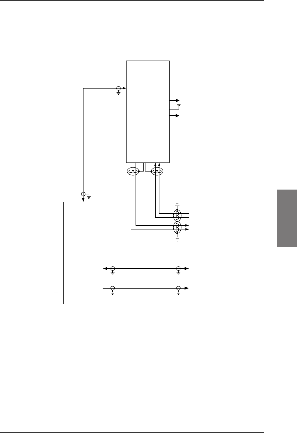
Electrical installation and wiring
98-127093-H Chapter 5: Installation 5-13
5555
Wiring HGA-6000 or HGA-6500
The following drawing shows the wiring for an AVIATOR 350 system using an HGA-6000 or
an HGA-6500 high gain antenna.
For the requirements to RF cables W1, W2 and W3 see Table 5-9 on page 5-24.
Figure 5-6: Wiring HGA-6000
/RVVG%#0+]
G%#0+]
'&UHVLVWDQFHȍ
:
:
:
77$
+/'
+*$
$QWHQQD
;
77$
6%8
$7[
$5[
73$
73$;
;
7[0RGHPDQG'&
5[
5[7[
-5)
9$36
*$B7[B$2XW
+$B7[B%2XW
0*1'$
$$B5[B$,Q
%$B5[B%,Q
9B'&,1<
9B5(76
-
9571
0D[Pȍ ;
/RVVG%#0+]
/RVVG%#0+]
%3'DWDWR%68%
%3'DWDWR%68$
%3'DWDIURP%68%
%3'DWDIURP%68$
9'&
'/1$%,7(
SB-Lite.book Page 13 Tuesday, September 5, 2017 1:38 PM
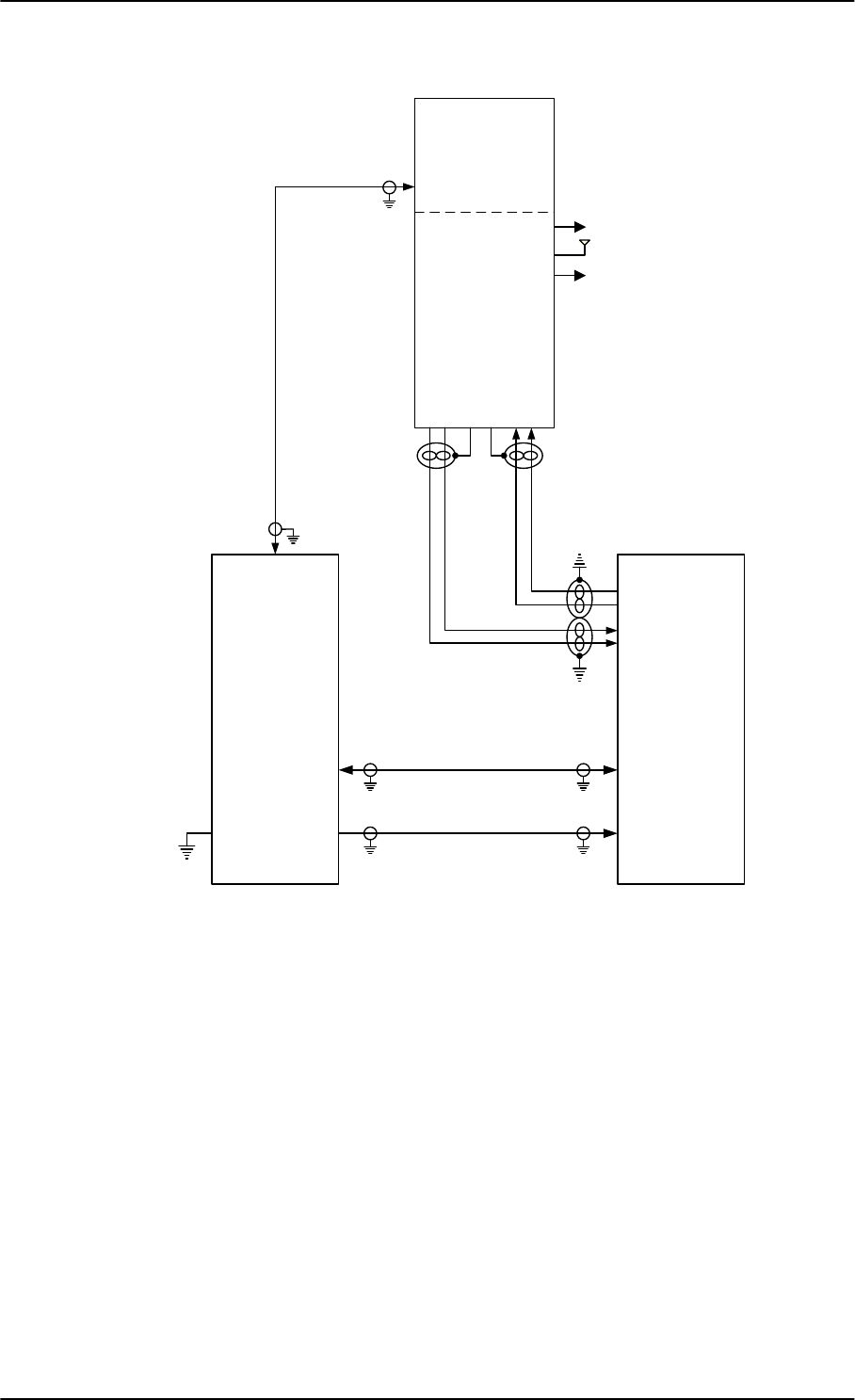
Electrical installation and wiring
5-14 Chapter 5: Installation 98-127093-H
For the requirements to RF cables W1, W2 and W3 see Table 5-9 on page 5-24.
Figure 5-7: Wiring HGA-6500 Antenna (Variation 2, label at antenna plug: 1 and 2)
/RVVG%#0+]
G%#0+]
'&UHVLVWDQFHȍ
:
:
:
77$
+/'
+*$
$QWHQQD
9DULDWLRQ
;
77$
6%8
$7[
$5[
73$
73$;
;
7[0RGHPDQG'&
5[
5[7[
-5)
9$36
$B7[B$2XW
$B7[B%2XW
*1'$
*1'$
$B5[B$,Q
$B5[B%,Q
9B'&,1
9B5(7
-
9571
0D[Pȍ ;
/RVVG%#0+]
/RVVG%#0+]
%3'DWDWR%68%
%3'DWDWR%68$
%3'DWDIURP%68%
%3'DWDIURP%68$
9'&
'/1$%,7(
SB-Lite.book Page 14 Tuesday, September 5, 2017 1:38 PM
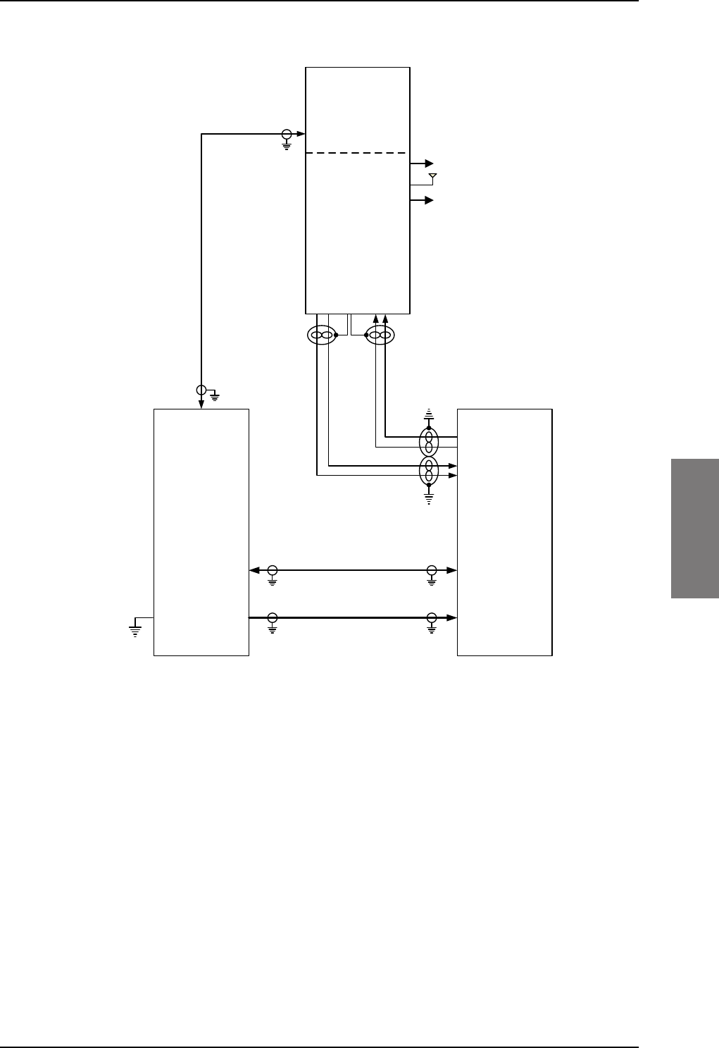
Electrical installation and wiring
98-127093-H Chapter 5: Installation 5-15
5555
For the requirements to RF cables W1, W2 and W3 see Table 5-9 on page 5-24.
Figure 5-8: Wiring HGA-6500 Antenna (Variation 3 label at antenna plug: Y and S)
/RVVG%#0+]
G%#0+]
'&UHVLVWDQFHȍ
:
:
:
77$
+/'
+*$
$QWHQQD
9DULDWLRQ
;
77$
6%8
$7[
$5[
73$
73$;
;
7[0RGHPDQG'&
5[
5[7[
-5)
9$36
*$B7[B$2XW
+$B7[B%2XW
0*1'$
$$B5[B$,Q
%$B5[B%,Q
9B'&,1<
9B5(76
-
9571
0D[Pȍ ;
/RVVG%#0+]
/RVVG%#0+]
%3'DWDWR%68%
%3'DWDWR%68$
%3'DWDIURP%68%
%3'DWDIURP%68$
9'&
'/1$%,7(
SB-Lite.book Page 15 Tuesday, September 5, 2017 1:38 PM
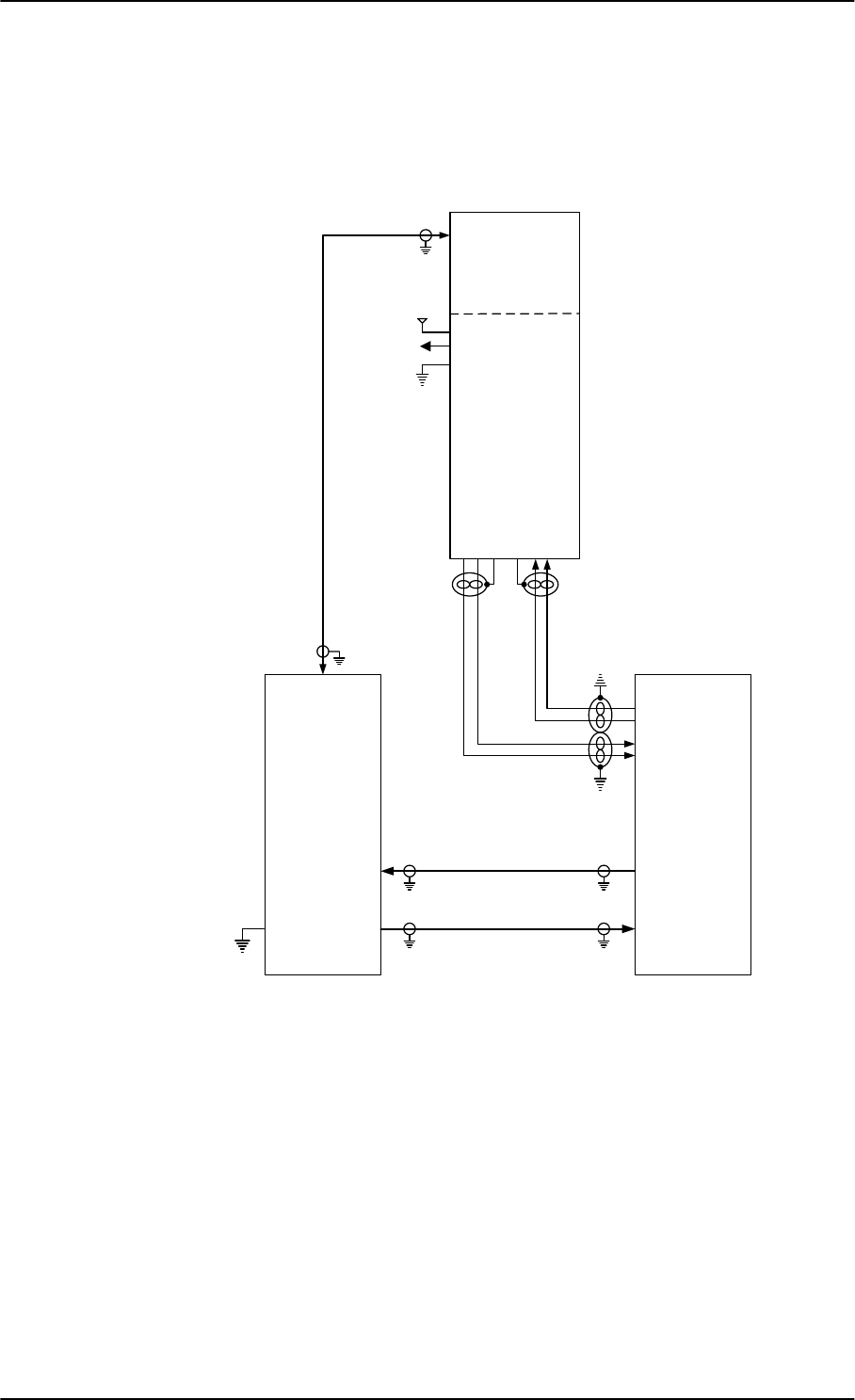
Electrical installation and wiring
5-16 Chapter 5: Installation 98-127093-H
Wiring HGA-7001
The following drawing shows the wiring for an AVIATOR 350 system using an HGA-7001
high gain antenna.
For the requirements to RF W1, W2 and W3 cables see Table 5-9 on page 5-24.
Figure 5-9: Wiring HGA-7001
77$
+/'
+*$
$QWHQQD
;
77$
6%8
$7[
$5[
73$
73$;
;
7[0RGHPDQG'&
5[
5[7[ $175)
1RFRQQHFW
9$36
$QWHQQD%,7($
$QWHQQD%,7(%
$QWHQQD%,7(6KLHOG
$QWHQQD&RQWURO6KLHOG
$QWHQQD&RQWURO$
$QWHQQD&RQWURO%
9'&
9'&571
&KDVVLV*QG
9571
0D[Pȍ ;
/RVVG%#0+]
/RVVG%#0+]
/RVVG%#0+]
G%#0+]
'&UHVLVWDQFHȍ
:
:
:
%3'DWDWR%68%
%3'DWDWR%68$
%3'DWDIURP%68%
%3'DWDIURP%68$
SB-Lite.book Page 16 Tuesday, September 5, 2017 1:38 PM
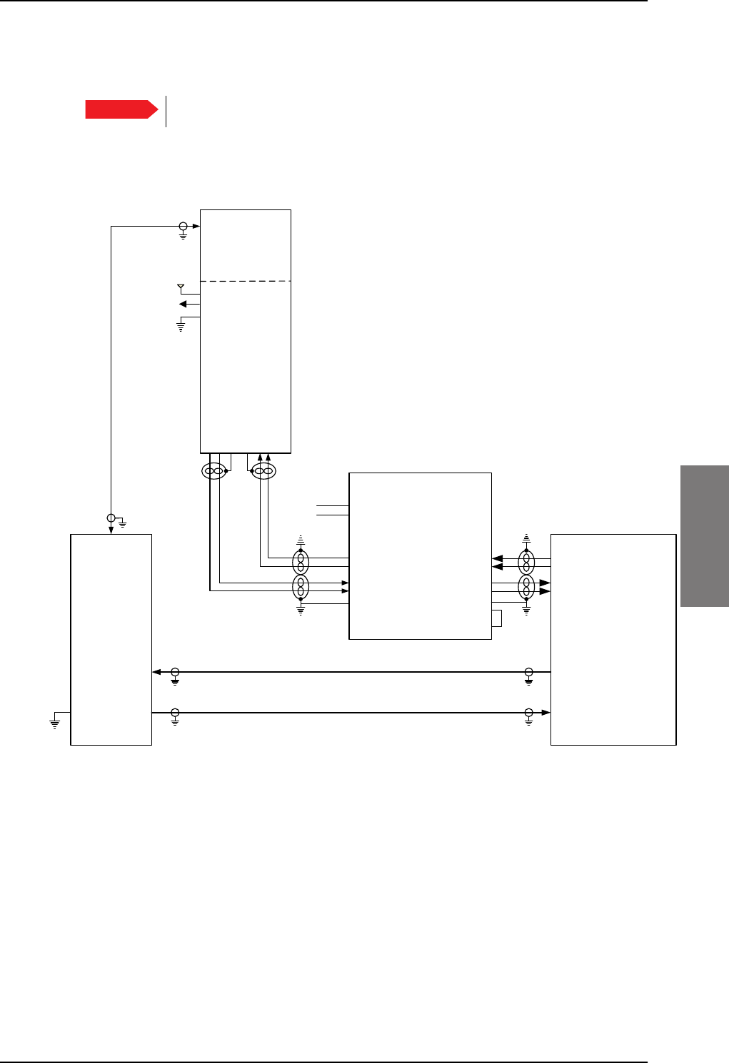
Electrical installation and wiring
98-127093-H Chapter 5: Installation 5-17
5555
AVIATOR 350: Wiring HGA-7001 with AIS 380 Aircraft Interface Module
The following drawing shows the wiring for an AVIATOR 350 system using an HGA-7001
high gain antenna and an AIS 380 Aircraft Interface Module.
Figure 5-10: Wiring HGA-7001 with AIS 380 Aircraft Interface Module
For the requirements to RF W1, W2 and W3 cables see Table 5-9 on page 5-24.
Important To use this feature the SBU must have software 2.03 or higher.
77$
+/'
+*$
$QWHQQD
;
77$
6%8
$7[
$5[
73$
73$;
;
7[0RGHPDQG'&
5[
5[7[
$175)
1RFRQQHFW
9$36
$QWHQQD%,7(%
$QWHQQD%,7($
$QWHQQD%,7(6KLHOG
$QWHQQD&RQWURO6KLHOG
$QWHQQD&RQWURO%
$QWHQQD&RQWURO$
9'&
9'&571
&KDVVLV*QG
9571
0D[Pȍ ;
/RVVG%#0+]
/RVVG%#0+]
/RVVG%#0+]
G%#0+]
'&UHVLVWDQFHȍ
:
:
:
732XWSXW%56
732XWSXW$56
73,QSXW%56
73,QSXW$56
6(55;
-
6(55;1(*
6(57;
6(57;1(*
$,6
-
$5,1&7;$
$5,1&7;%
$5,1&5;$
$5,1&5;%
3:55(7851
93:5
&+$66,6*1'
9'&
*1'
&+$66,6*1'
',6&5(7(,2
',6&5(7(,2
*5281'
1RWHIRU$,6
3LQ',6&5(7(,2'LVFUHWH7;6SHHG6HOHFW2SHQ $5,1&+,
3LQ',6&5(7(,2'LVFUHWH5;6SHHG6HOHFW*1' $5,1&/2
SB-Lite.book Page 17 Tuesday, September 5, 2017 1:38 PM
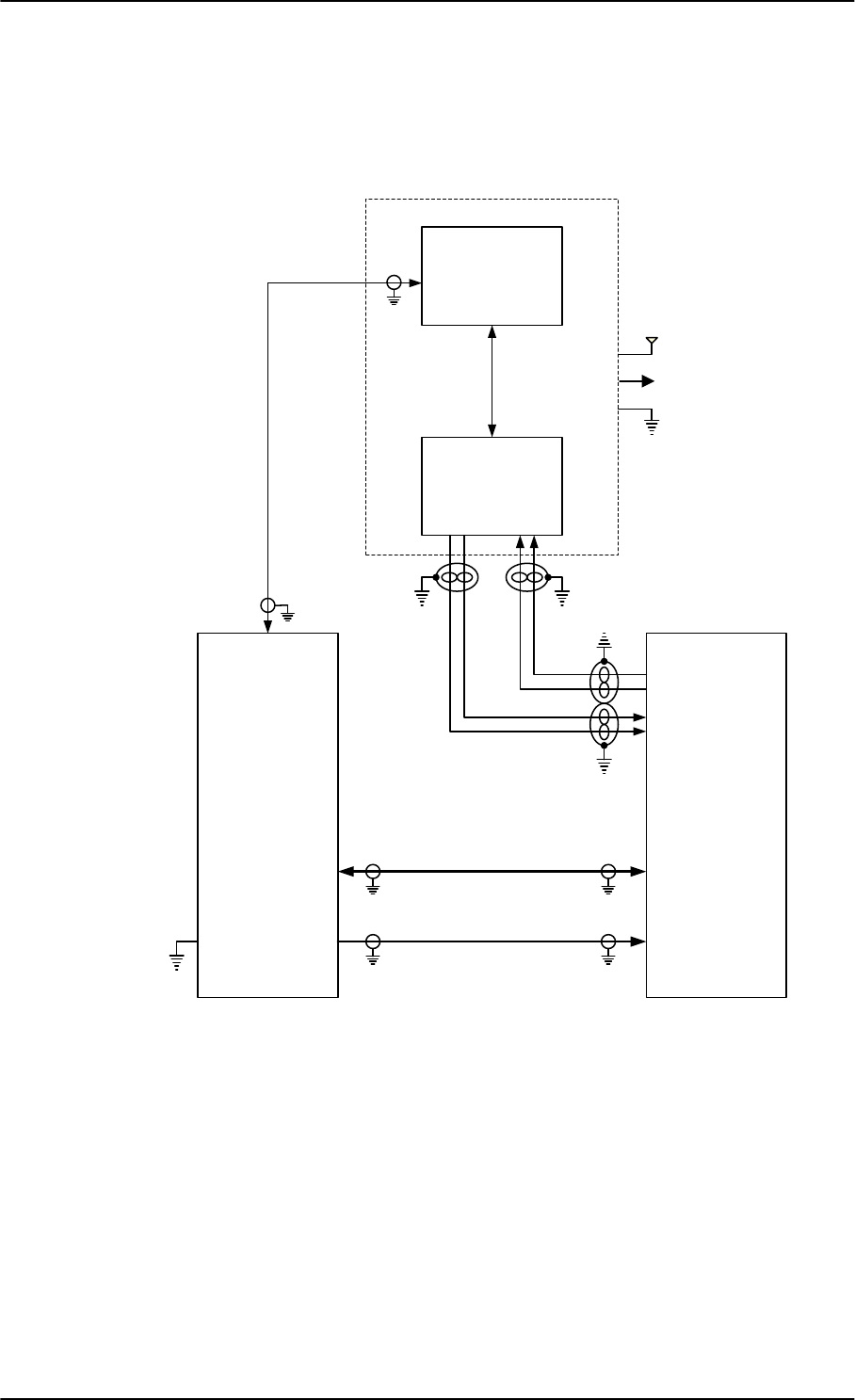
Electrical installation and wiring
5-18 Chapter 5: Installation 98-127093-H
Wiring AMT-50
The following drawing shows the wiring for an AVIATOR 350 system using an AMT-50 high
gain antenna.
For the requirements to RF cables W1, W2 and W3 see Table 5-9 on page 5-24.
Figure 5-11: Wiring AMT-50
:
:
:
77$
+/'
$07
$&8
$%
$076XEV\VWHP
$07
$QWHQQD
;
77$
6%8
*+
$7[
$5[
73$
73$;
;
7[0RGHPDQG'&
5[
5[7[
;
0D[Pȍ
/RVVG%#0+]
/RVVG%#0+]
/RVVG%#0+]
G%#0+]
'&UHVLVWDQFHȍ
9$36
9571
9'&9<
9'&57136
&KDVVLV*URXQG0
%3'DWDWR%68%
%3'DWDWR%68$
%3'DWDIURP%68%
%3'DWDIURP%68$
SB-Lite.book Page 18 Tuesday, September 5, 2017 1:38 PM
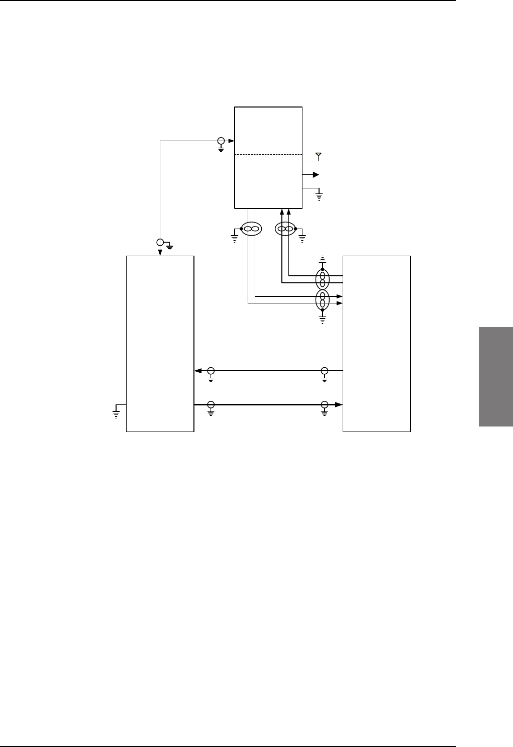
Electrical installation and wiring
98-127093-H Chapter 5: Installation 5-19
5555
Wiring AMT-700
The following drawing shows the wiring for an AVIATOR 350 system using an AMT-700
high gain antenna.
For the requirements to RF W1, W2 and W3 cables see Table 5-9 on page 5-24.
Figure 5-12: Wiring AMT-700
77$
+/'
$07
+*$
$%
;
77$
6%8
*+
$7[
$5[
73$
73$;
;
7[0RGHPDQG'&
5[
5[7[
;
0D[Pȍ
/RVVG%#0+]
/RVVG%#0+]
/RVVG%#0+]
G%#0+]
'&UHVLVWDQFHȍ
9$36
9571
9'&9<
9'&57136
&KDVVLV*URXQG0
-
-
:
:
:
%3'DWDWR%68%
%3'DWDWR%68$
%3'DWDIURP%68%
%3'DWDIURP%68$
SB-Lite.book Page 19 Tuesday, September 5, 2017 1:38 PM
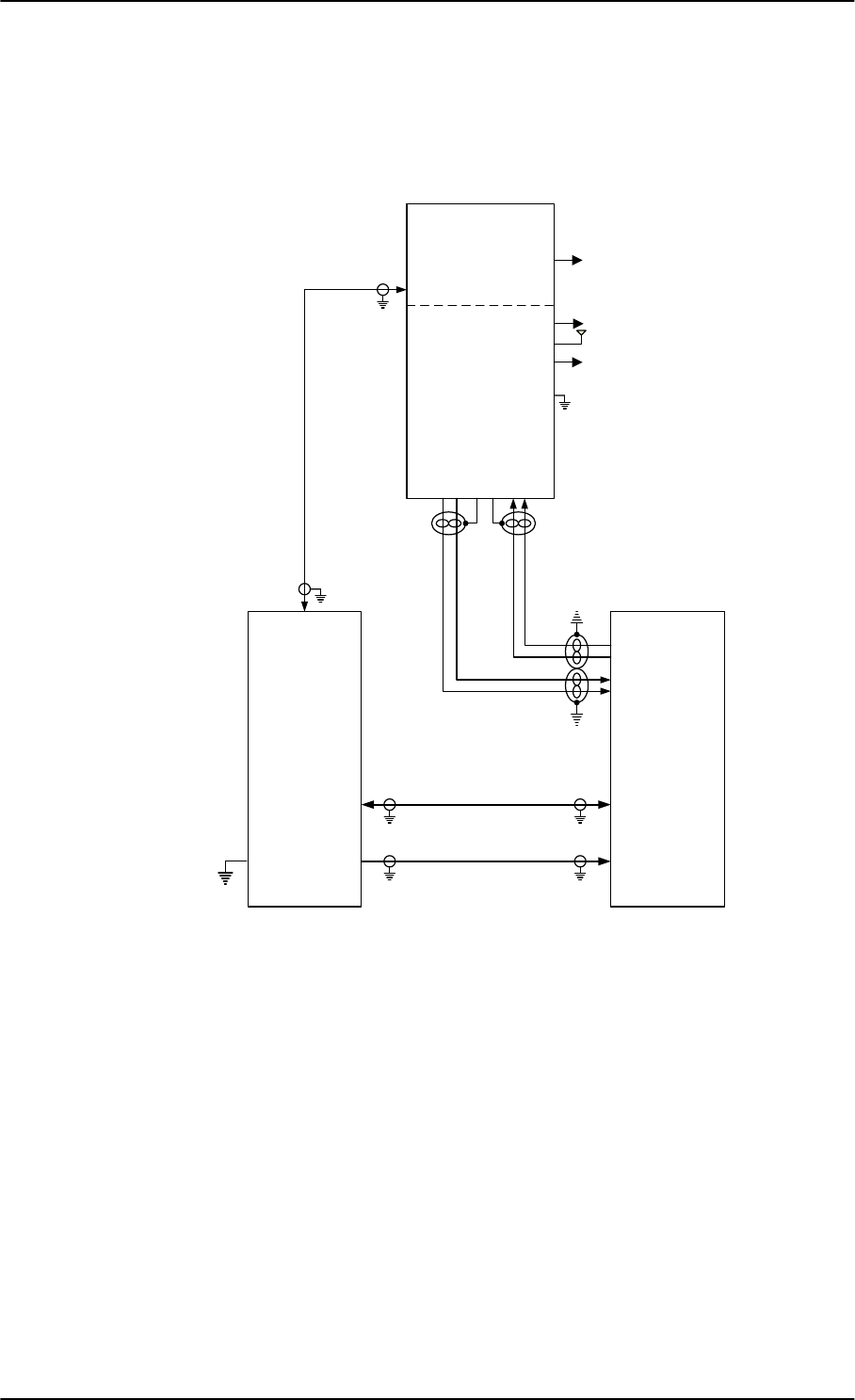
Electrical installation and wiring
5-20 Chapter 5: Installation 98-127093-H
Wiring AMT-3500/3800
The following drawing shows the wiring for an AVIATOR 300 system using an AMT-3500
intermediate gain antenna or an AVIATOR 350 using an AMT-3800 high gain antenna.
For the requirements to RF W1, W2 and W3 cables see Table 5-9 on page 5-24.
Figure 5-13: Wiring AMT-3500/3800
/RVVG%#0+]
G%#0+]
'&UHVLVWDQFHȍ
:
:
:
77$
+/'
$07
$QWHQQD
;
77$
6%8
$7[
$5[
73$
73$;
;
7[0RGHPDQG'&
5[
5[7[
%3'DWDWR%68%
%3'DWDWR%68$
%3'DWDIURP%68%
%3'DWDIURP%68$
-5)
9$36
$QWHQQD%,7($
$QWHQQD%,7(%
$QWHQQD&RQWURO$
$QWHQQD&RQWURO%
'/1$%,7(
9B'&,1
9B5(7
-
9571
0D[Pȍ ;
/RVVG%#0+]
/RVVG%#0+]
9'&
SB-Lite.book Page 20 Tuesday, September 5, 2017 1:38 PM
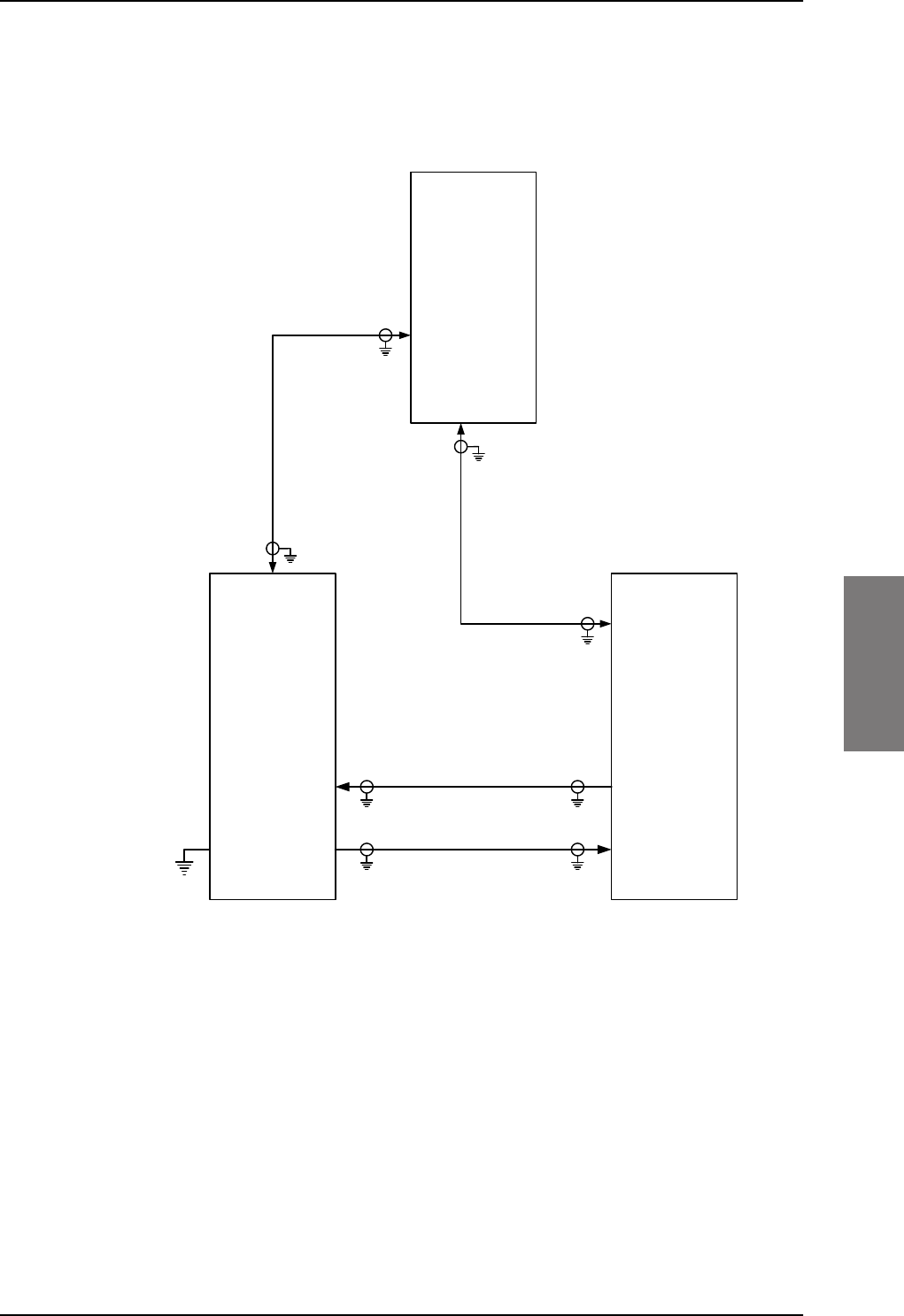
Electrical installation and wiring
98-127093-H Chapter 5: Installation 5-21
5555
Wiring IGA-5001, HGA-7000 and HGA-8000
The following drawing shows the wiring for an AVIATOR 300 system using an IGA-5001 or
an AVIATOR 350 system using a HGA-7000 or HGA-8000.
For the requirements to RF cables W1, W2, W3 and W4 see Table 5-9 on page 5-24.
Figure 5-14: Wiring IGA-5001. HGA-7000 and HGA-8000
77$
+/'
,*$
+*$
+*$
$QWHQQD
;
77$
6%8
73$
73$;
;
7[0RGHPDQG'&
5[
5[7[
-%OXH5)
'&*36&RQWURO
-5HG
*36$QWHQQDPRGHP'&
%3$
0D[Pȍ ;
/RVVG%#0+]
/RVVG%#0+]
/RVVG%#0+]
G%#0+]
'&UHVLVWDQFHȍ
/RVVG%#0+]
:
:
:
:
SB-Lite.book Page 21 Tuesday, September 5, 2017 1:38 PM
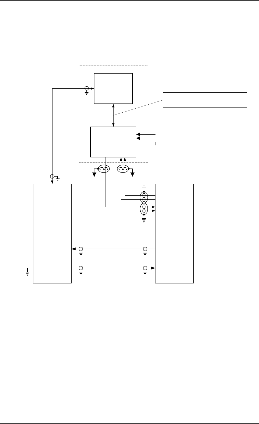
Electrical installation and wiring
5-22 Chapter 5: Installation 98-127093-H
Wiring CMA-2102/CMA-2102SB
The following drawing shows the wiring for an AVIATOR 350 system using a CMA-2102SB
antenna.
For the requirements to RF cables W1, W2 and W3 see Table 5-9 on page 5-24.
Figure 5-15: Wiring CMA-2102/CMA-2102SB
77$
+/'
%68
-73
&'
&0$6XEV\VWHP
+*$
;
77$
6%8
-73
&'
$7[
$5[
73$
73$;
;
7[0RGHPDQG'&
5[
5[7[
;
0D[Pȍ
/RVVG%#0+]
/RVVG%#0+]
/RVVG%#0+]
G%#0+]
'&UHVLVWDQFHȍ
9$&+27
9$&&2/'
-%3
-%3
-%3
-
6HH,QVWDOODWLRQ0DQXDOIRU&0$$LUERUQH6DWHOOLWH
&RPPXQLFDWLRQ$QWHQQD6\VWHPIRUGHWDLOV
:
:
:
%3'DWDWR%68%
%3'DWDWR%68$
%3'DWDIURP%68%
%3'DWDIURP%68$
SB-Lite.book Page 22 Tuesday, September 5, 2017 1:38 PM
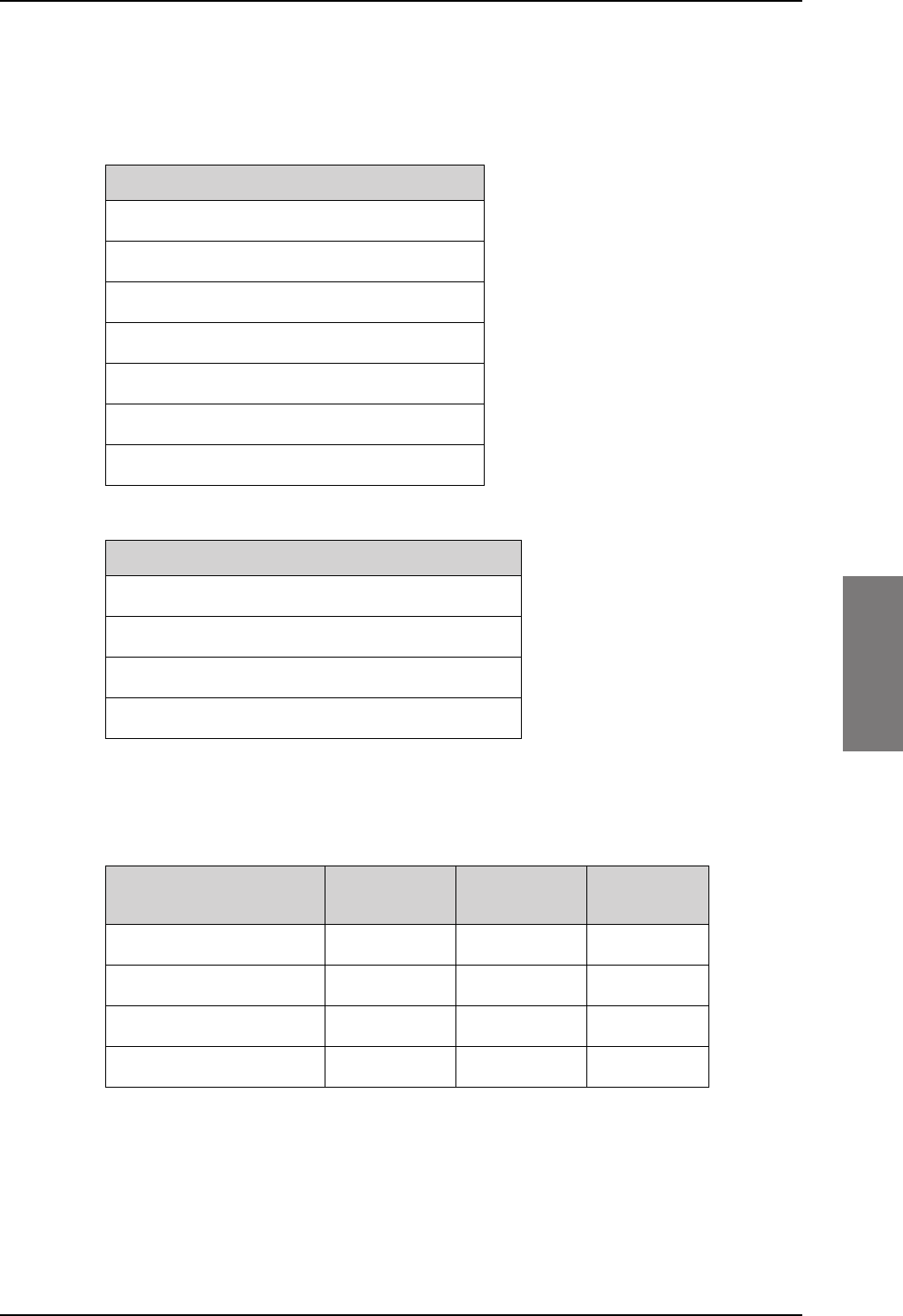
Electrical installation and wiring
98-127093-H Chapter 5: Installation 5-23
5555
Pins for connecting to HLD and SBU
The following list shows the pins used in the AVIATOR 200/300/350 system for connecting
the satcom antenna to the HLD and SBU.
The following tables show the requirements to cable losses for cables between the satcom
antenna, the HLD and the SBU. The cable loop DC resistance is the sum of the resistance in
the shield and the center conductor.
Table 5-8: RF cable requirements for satcom antenna systems, AVIATOR 200
W1 (SBU Tx to HLD Tx)a
a. Additional requirements: Antenna cable modem-attenuation: at 54 MHz: max. 4
dB, at 36 MHz: max. 3 dB.
0 dB 17 dB < 0.6
W2 (HLD Rx to SBU Rx) 0 dB 17 dB n.a.
W3 (HLD to antenna) 0 dB 0.3 dB n.a.
W4 (SBU to antenna) 0 dB 17 dB < 1.5
SBU pin Description
TP A1 RF Tx output to HLD
TP A3 RF Rx input from HLD
BP A4 GPS input, DC out, Modem (coax.)
BP12 Data to BSU or CMU, ARINC 429A
BP18 Data to BSU or CMU, ARINC 429 B
BP9 Data from BSU or CMU, ARINC 429A
BP14 Data from BSU or CMU, ARINC 429 B
Table 5-6: SBU pins for satcom antenna system
HLD connector Description
X1 L-Band Rx/Tx interface to antenna
X2 RF Tx input from SBU
X3 RF Rx output to SBU
X4 Chassis Ground
Table 5-7: HLD connectors for satcom antenna system
RF cable requirements for
AVIATOR 200
Min. cable
Loss @1.6 GHz
Max. cable
Loss @1.6 GHz
Cable loop
DC resistance
SB-Lite.book Page 23 Tuesday, September 5, 2017 1:38 PM

Table 5-9: RF cable requirements for satcom antenna systems, AVIATOR 300/350
W1 (SBU Tx to HLD Tx)a
a. Additional requirements: Antenna cable modem-attenuation at 54 MHz: max. 4 dB, at
36 MHz: max. 3 dB.
0 dB 18 dB < 0.6
W2 (HLD Rx to SBU Rx) 0 dB 20 dB n.a.
W3 (HLD to antenna) 0 dB 0.7 dBb
b. 0.3 dB for AMT-3500/3800.
n.a.
W4 (SBU to antenna) 0 dB 17 dB < 1.5
Electrical installation and wiring
5-24 Chapter 5: Installation 98-127093-H
RF cable requirements for
AVIATOR 300 and AVIATOR 350
Min. cable
Loss @1.6 GHz
Max. cable
Loss @1.6 GHz
Cable loop
DC resistance
SB-Lite.book Page 24 Tuesday, September 5, 2017 1:38 PM
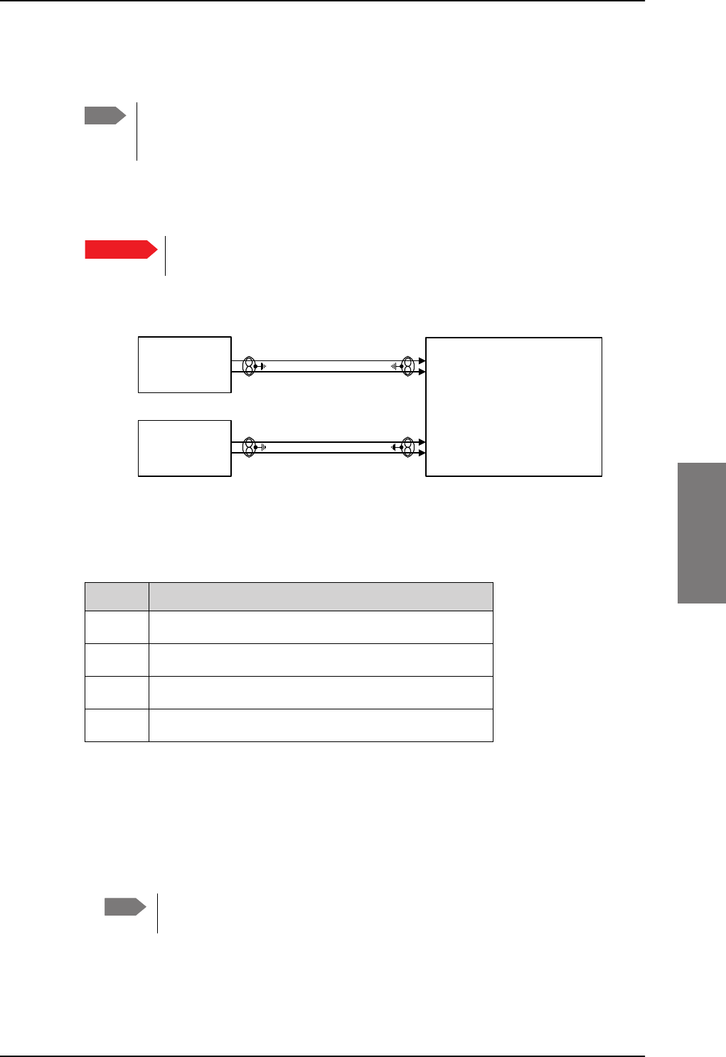
Electrical installation and wiring
98-127093-H Chapter 5: Installation 5-25
5555
5.3.4 Wiring ARINC 429 interfaces
Wiring an ARINC 429 source system
The SBU has two ARINC 429 input interfaces for two navigational inputs.
For instructions how to install and set up the IRS, AHRS, NPI or GNSS system
see the respective installation manual.
The following drawing shows the wiring of a navigational input. Requirements to the cables
are stated in the section Cable requirements, ARINC 429 on page 5-29.
Pins for input from ARINC 429 sources
The pins for navigational input are located in the bottom plug of the SBU rear receptacle.
Description of the interface for navigational input
When the system is configured with the web interface, the CM contains the information:
• Which navigational input is selected: IRS, AHRS, NPI or GNSS.
• Whether primary or secondary input or both are installed.
If primary and secondary ARINC 429 navigational input are both installed,
they must be of the same type (IRS, AHRS, NPI or GNSS).
• ARINC 429 Speed (High or Low). The primary and secondary navigational inputs can
individually be set to high or low speed, depending on your configuration.
Note The source for navigational data over ARINC 429 can be either an IRS, AHRS, NPI,
GNSS or another navigational input compatible with the requirements in this
section.
Important
Figure 5-16: Wiring ARINC 429 navigational input
6HFRQGDU\
$5,1&
+6/6$5,1&5;
3ULPDU\
$5,1&
+6/6$5,1&5;
77$
6%8
%3
%3
%3
%3
SBU pin Name/description
BP5 Data from primary ARINC 429 navigational input A
BP8 Data from primary ARINC 429 navigational input B
BP7 Data from secondary ARINC 429 navigational input A
BP13 Data from secondary ARINC 429 navigational input B
Table 5-10: SBU pins for input from a navigational ARINC 429 source
Note
SB-Lite.book Page 25 Tuesday, September 5, 2017 1:38 PM
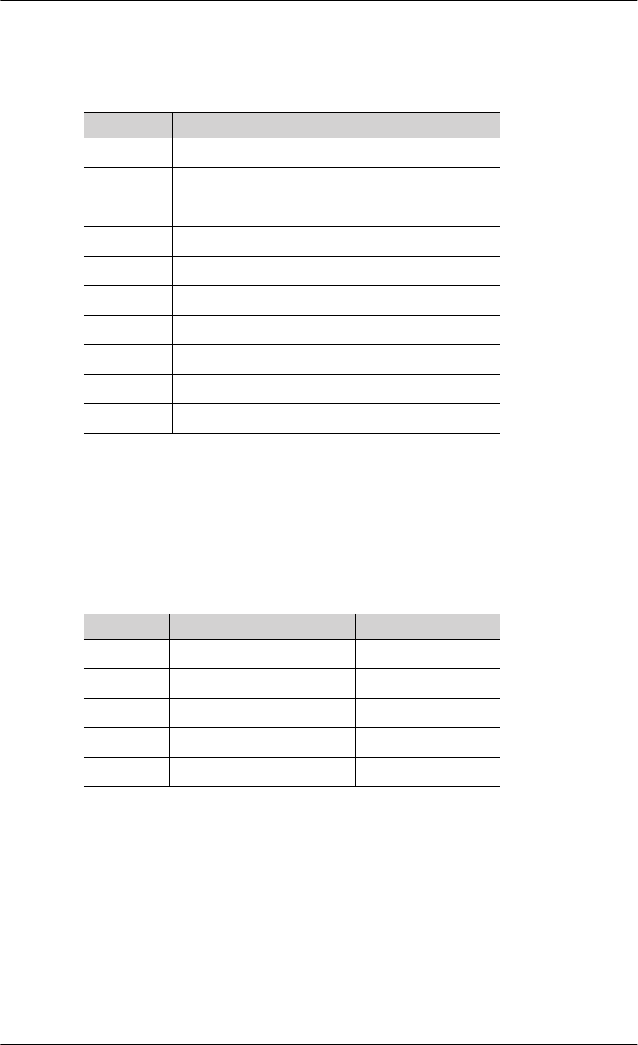
Electrical installation and wiring
5-26 Chapter 5: Installation 98-127093-H
ARINC data format for IRS
The required ARINC data format for IRS is listed in the following table:
ARINC data format for AHRS
The required ARINC data format for AHRS is listed in the following table:
Label (octal) Name Minimum update rate
150 UTC Time (optional)a1 Hz
260 UTC Date (optional)a1 Hz
310 Latitude 1 Hz
311 Longitude 1 Hz
312 Ground speed 1 Hz
313 Track angle True 1 Hz
314 True heading 10 Hz
324 Pitch angle 10 Hz
325 Roll angle 10 Hz
361 Altitude Inertial (optional)a
a. The labels marked optional do not have an effect on the operation
of the AVIATOR 200/300/350 system, but may increase precision in
the antenna pointing and time management.
1 Hz
Table 5-11: ARINC data format for IRS
Label (octal) Name Minimum update rate
320 Magnetic heading 10 Hz
324 Pitch angle 10 Hz
325 Roll angle 10 Hz
336 Inertial pitch rate (optional)a
a. The labels marked optional do not have an effect on the operation
of the AVIATOR 200/300/350 system, but may increase precision in
the antenna pointing.
10 Hz
337 Inertial roll rate (optional)a10 Hz
Table 5-12: ARINC data format for AHRS
SB-Lite.book Page 26 Tuesday, September 5, 2017 1:38 PM
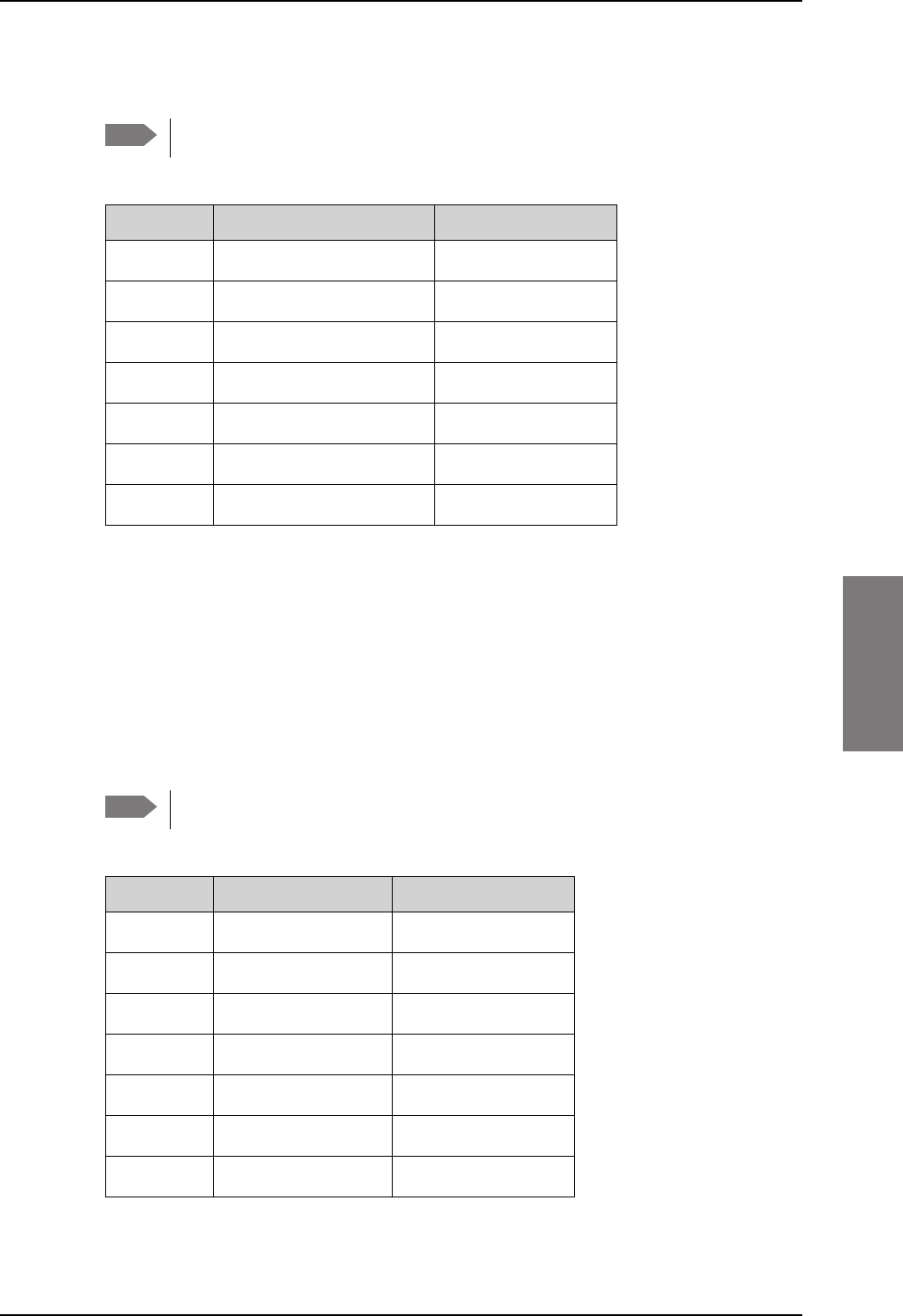
Electrical installation and wiring
98-127093-H Chapter 5: Installation 5-27
5555
ARINC data format for NPI
The required ARINC data format for NPI is listed in the following table:
Table 5-13: ARINC data format for NPI
150 UTC Time (optional)a
a. The labels marked optional do not have an effect on the operation
of the AVIATOR 200 system, but may increase precision in the
time management.
1 Hz
260 UTC Date (optional)a1 Hz
310 Latitude 1 Hz
311 Longitude 1 Hz
312 Ground speed 1 Hz
313 Track angle Trueb
b. The SBU software only checks for the track angle when the ground
speed is above 100 knots. This is applicable from version AVIATOR
200/300/350 (Level E): 1.07 and above, AVIATOR
200D/300D/350D (Level D): 2.01 and above.
1 Hz
361 Altitude Inertial (optional)a1 Hz
ARINC data format for GNSS
The required ARINC data format for GNSS is listed in the following table:
Table 5-14: ARINC data format for GNSS
103 Track anglea1 Hz
110 Latitude 1 Hz
111 Longitude 1 Hz
112 Ground speed 1 Hz
150 UTC Time (optional)b1 Hz
260 UTC Date (optional) 1 Hz
370 Height (optional) 1 Hz
Note NPI can only be used together with the AVIATOR 200 (TT-3002A LGA).
Label (octal) Name Minimum update rate
Note GNSS can only be used together with the AVIATOR 200 (TT-3002A LGA).
Label (octal) Name Minimum update rate
SB-Lite.book Page 27 Tuesday, September 5, 2017 1:38 PM
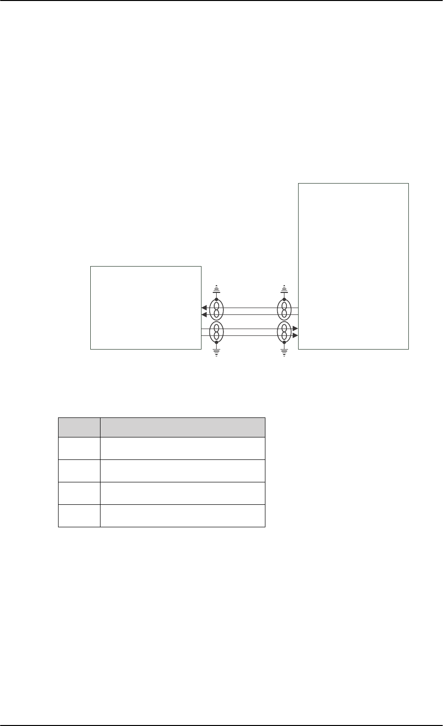
Electrical installation and wiring
5-28 Chapter 5: Installation 98-127093-H
Wiring CMU
The following figure shows the wiring of the SBU to a CMU via ARINC 429 Tx / Rx interface.
Figure 5-17: Wiring the CMU
Pins for CMU
a. The SBU software only checks for the track angle when the
ground speed is above 100 knots. This is applicable from
version AVIATOR 200/300/350 (Level E): 1.07 and above,
AVIATOR 200D/300D/350D (Level D): 2.01 and above.
b. The labels marked optional do not have an effect on the
operation of the AVIATOR 200 system, but may increase
precision in the time management.
ddͲϱϬϰϬ
^h
Dh ϰϮϵddž
Wϭϴ
WϭϮ
Wϭϰ
Wϵ
ϰϮϵZdž
SBU pin Name/description
BP9 Data from BSU or CMU, ARINC 429A
BP14 Data from BSU or CMU, ARINC 429B
BP12 Data to BSU or CMU, ARINC 429A
BP18 Data to BSU or CMU, ARINC 429B
Table 5-15: SBU pins for input from GPS antenna
SB-Lite.book Page 28 Tuesday, September 5, 2017 1:38 PM
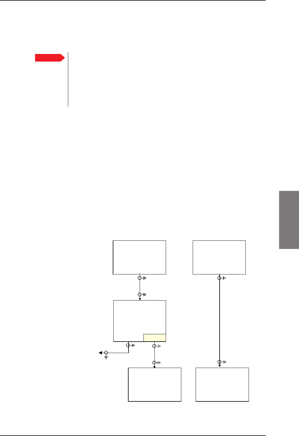
Electrical installation and wiring
98-127093-H Chapter 5: Installation 5-29
5555
Description
To configure installation parameters for ACARS/CMU in the web interface of the SBU see
Set up CMU/ACARS (option) on page 6-51.
When using the SBU/ACARS interface for SBB Safety Services (e.g. CPDLC
traffic) and/or SB-Safety Voice is enabled, note that additional user traffic and
interface connections to the SBU shall be addressed in the Security Safety
Assessment (SSA) of the particular aircraft. The SBU does not comply to the
ARINC-781 attachment 8, Security Considerations. There is no segregation
between the user interfaces. All interfaces of the SBU shall be considered as
'Aircraft Control Domain'.
Cable requirements, ARINC 429
The cables for the ARINC 429 interfaces must be twisted and shielded. They must conform
to the standards for aeronautical use.
For recommended cable types, see Recommended cables for ARINC 429 on page 5-49.
5.3.5 Wiring GPS interface
Wiring the GPS antenna
The following figure shows the wiring of the GPS interface when using a power splitter. You
can use the power splitter shown in TT-5038A-003 Rx Power Splitter on page 3-4. In this
configuration, the other GPS receiver must power the antenna.
The SBU also has the ability to power an antenna with either 5 VDC or 26 VDC if a separate
GPS antenna is connected directly to the SBU.
Figure 5-18: Wiring GPS Interface with Power Splitter
Important
'&%/2&.
*36
$QWHQQD
3RZHU6SOLWWHU
G%#*+=
*36
DQWHQQD
$LUFUDIW
6%8
77$
6%8
%3$
*36LQ
2WKHU$LUFUDIW
,QVWDOODWLRQ
*36
$QWHQQD
77$
6%8
%3$
*36LQ
SB-Lite.book Page 29 Tuesday, September 5, 2017 1:38 PM

Electrical installation and wiring
5-30 Chapter 5: Installation 98-127093-H
The cable loss limit between the GPS Antenna and the SBU depends on the active gain in
the GPS antenna. The gain, minus the total loss in the cable(s) and Power Splitter must be in
the range of 10 to 35 dB.
Satcom Rejection: The GPS antenna must comply with DO-310. In particular section
2.2.6.3 and the requirement to withstand +8
dBm at frequencies above 1625 MHz.
Antennas that are approved under TSO-C144 or TSO-C190 meet this requirement.
Pin for input from the GPS antenna
Description of the GPS interface
This section describes the GPS interface when used to interface with a standalone GPS
antenna. This interface is also used when connecting to a satcom antenna with built-in GPS
antenna. For info on this, please see Wiring the satcom antenna on page 5-10.
The GPS interface has 3 functions:
• Reception of the GPS RF signal
• Supply DC power to the GPS antenna or satcom antenna
• Coax modem communication with the satcom antenna
SBU pin Name/description
BP A4 GPS antenna input (coax), modem, DC out
Table 5-16: SBU pins for input from GPS antenna
SB-Lite.book Page 30 Tuesday, September 5, 2017 1:38 PM
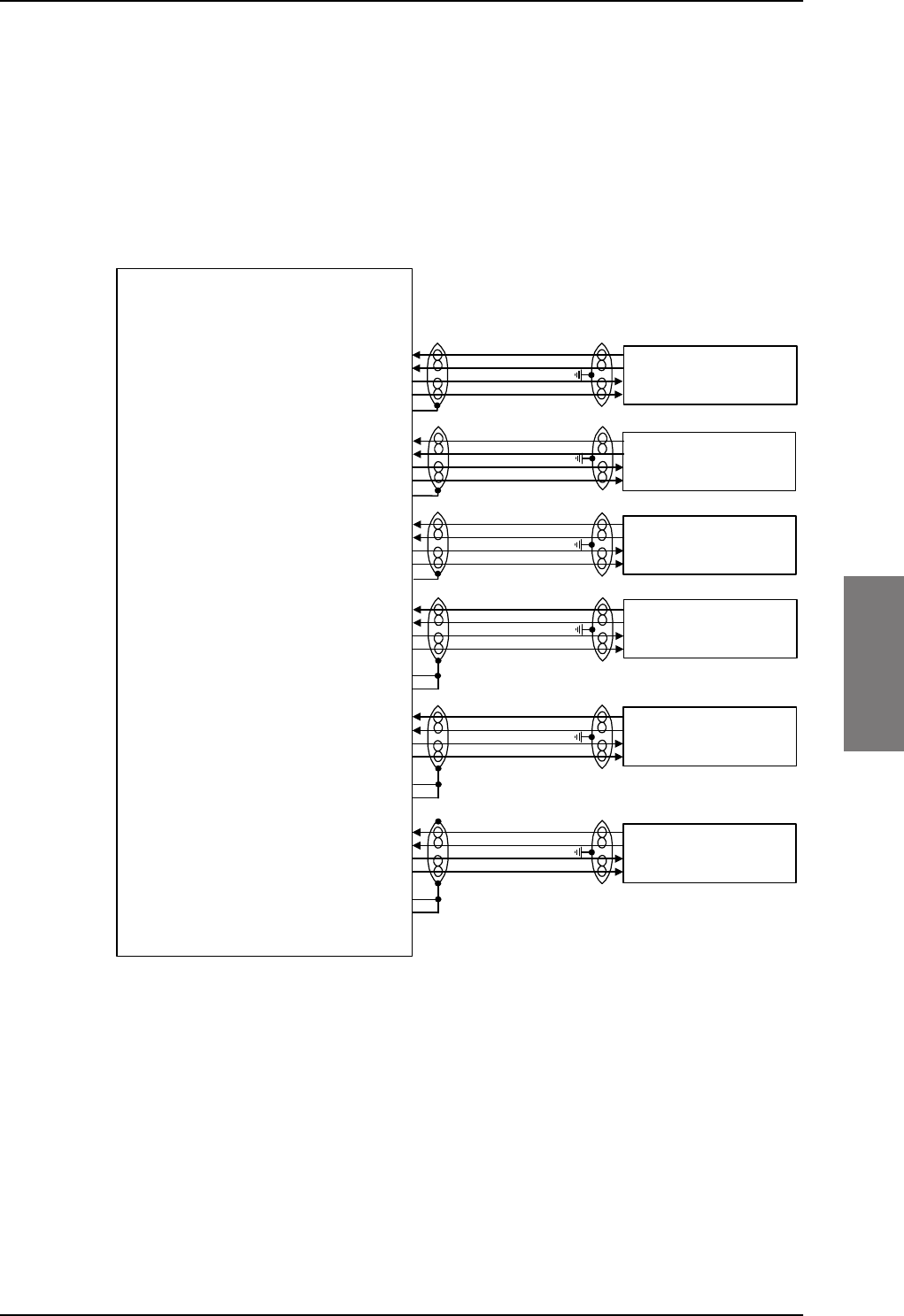
Electrical installation and wiring
98-127093-H Chapter 5: Installation 5-31
5555
5.3.6 Wiring Ethernet
Overview
The SBU has six 10/100BaseT Ethernet interfaces, plus the interface on the front of the
SBU described in Wiring the maintenance interface on page 5-45.
The following drawing shows the wiring of the rear SBU Ethernet interfaces.
The RJ45 Ethernet interfaces match a standard straight network cable. You can freely select
which of the Ethernet connections you want to use.
The supported cable length is up to 100 meters (328 feet).
Figure 5-19: Wiring Ethernet
77$
6%8
7[%DVH7(WKHUQHWLQSXW%3$
7[%DVH7(WKHUQHWLQSXW%3$
5[%DVH7(WKHUQHWRXWSXW%3$
5[%DVH7(WKHUQHWRXWSXW%3$
%3$VKLHOG
7[%DVH7(WKHUQHWLQSXW%3$
7[%DVH7(WKHUQHWLQSXW%3$
5[%DVH7(WKHUQHWRXWSXW%3$
5[%DVH7(WKHUQHWRXWSXW%3$
%3$VKLHOG
7[%DVH7(WKHUQHWLQSXW%3$
7[%DVH7(WKHUQHWLQSXW%3$
5[%DVH7(WKHUQHWRXWSXW%3$
5[%DVH7(WKHUQHWRXWSXW%3$
%3$VKLHOG
7[%DVH7(WKHUQHWLQSXW%3
7[%DVH7(WKHUQHWLQSXW%3
5[%DVH7(WKHUQHWRXWSXW%3
5[%DVH7(WKHUQHWRXWSXW%3
7[%DVH7(WKHUQHWLQSXW%3
7[%DVH7(WKHUQHWLQSXW%3
5[%DVH7(WKHUQHWRXWSXW%3
5[%DVH7(WKHUQHWRXWSXW%3
7[%DVH7(WKHUQHWLQSXW%3
7[%DVH7(WKHUQHWLQSXW%3
5[%DVH7(WKHUQHWRXWSXW%3
5[%DVH7(WKHUQHWRXWSXW%3
5-
)HPDOH&RQQHFWRU
5-
)HPDOH&RQQHFWRU
5-
)HPDOH&RQQHFWRU
5-
)HPDOH&RQQHFWRU
5-
)HPDOH&RQQHFWRU
5-
)HPDOH&RQQHFWRU
&RPPRQ6LJQDO*1'%3
&RPPRQ6LJQDO*1'%3
&RPPRQ6LJQDO*1'%3
&RPPRQ6LJQDO*1'%3
&RPPRQ6LJQDO*1'%3
&RPPRQ6LJQDO*1'%3
SB-Lite.book Page 31 Tuesday, September 5, 2017 1:38 PM

Electrical installation and wiring
5-32 Chapter 5: Installation 98-127093-H
Pins for 10/100BaseT Ethernet
The following list shows the pins used for the Ethernet interface.
SBU pin Name Description RJ45 pin (F) Name
BP A1.1 Tx+ 10/100BaseT Ethernet #1 Input 1 TxD+
BP A1.2 Rx+ 10/100BaseT Ethernet #1 Output 3 RxD+
BP A1.3 Tx- 10/100BaseT Ethernet #1 Input 2 TxD-
BP A1.4 Rx- 10/100BaseT Ethernet #1 Output 6 RxD-
BP A2.1 Tx+ 10/100BaseT Ethernet #2 Input 1 TxD+
BP A2.2 Rx+ 10/100BaseT Ethernet #2 Output 3 RxD+
BP A2.3 Tx- 10/100BaseT Ethernet #2 Input 2 TxD-
BP A2.4 Rx- 10/100BaseT Ethernet #2 Output 6 RxD-
BP A3.1 Tx+ 10/100BaseT Ethernet #3 Input 1 TxD+
BP A3.2 Rx+ 10/100BaseT Ethernet #3 Output 3 RxD+
BP A3.3 Tx- 10/100BaseT Ethernet #3 Input 2 TxD-
BP A3.4 Rx- 10/100BaseT Ethernet #3 Output 6 RxD-
BP6 Rx- 10/100BaseT Ethernet #4 Output 6 RxD-
BP10 Tx+ 10/100BaseT Ethernet #4 Input 1 TxD+
BP11 Tx- 10/100BaseT Ethernet #4 Input 2 TxD-
BP15 Common Signal GND for Ethernet GND Shield
BP16 Rx+ 10/100BaseT Ethernet #4 Output 3 RxD+
BP17 Common Signal GND for Ethernet GND Shield
BP19 Rx- 10/100BaseT Ethernet #5 Output 6 RxD-
BP20 Tx- 10/100BaseT Ethernet #5 Input 2 TxD-
BP21 Common Signal GND for Ethernet GND Shield
BP22 Common Signal GND for Ethernet GND Shield
BP23 Rx- 10/100BaseT Ethernet #6 Output 6 RxD-
BP24 Tx- 10/100BaseT Ethernet #6 Input 2 TxD-
BP25 Tx+ 10/100BaseT Ethernet #5 Input 1 TxD+
Table 5-17: SBU Pins for 10/100BaseT Ethernet
SB-Lite.book Page 32 Tuesday, September 5, 2017 1:38 PM
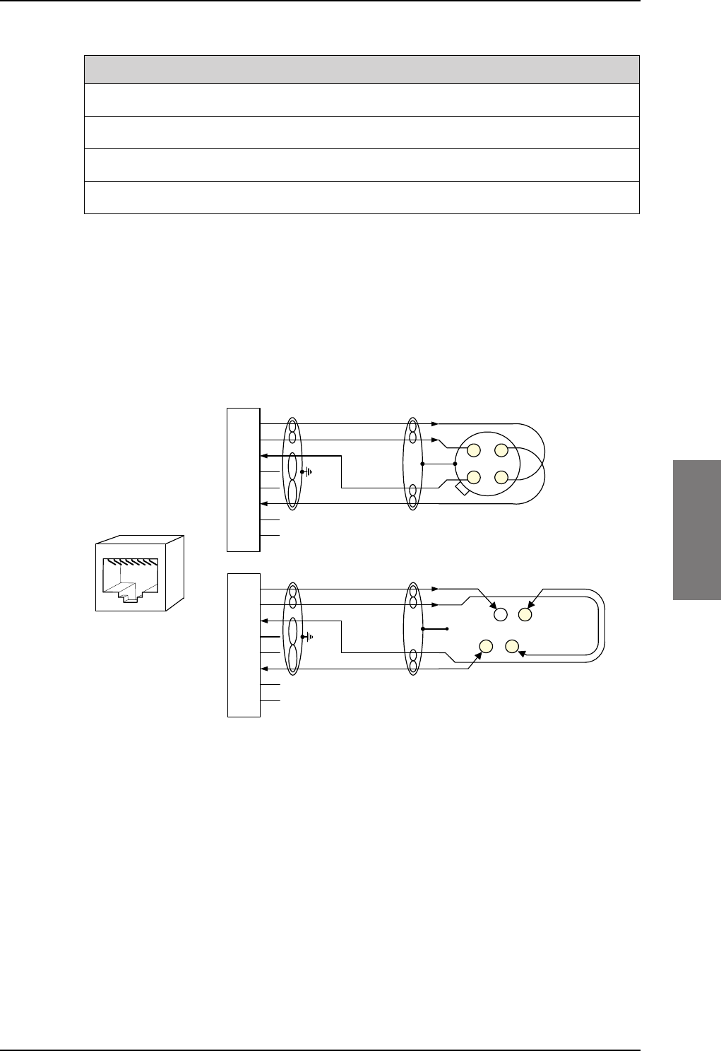
Electrical installation and wiring
98-127093-H Chapter 5: Installation 5-33
5555
Wiring of RJ45 connector to Quadrax connector
The physical layer conforms to IEEE standard 802.3 [1], Chapter 14: “Twisted Pair medium
attachment unit”, except for the connector type. To be compliant with [1], use an RJ45
female connector for the user interface. The below drawing shows the corresponding RJ45
connection. The SBU is configured as Data communication Equipment (DCE), i.e. TX +/- are
input and RX +/- are outputs.
Figure 5-20: Ethernet pin configuration for SBU
Common Signal GND (BP15, BP17, BP21, BP22 and BP27)
Common Signal GND is used to connect the shield of the Ethernet cables for Ethernet #4,
#5 and #6 on the SBU. The shield for each cable is connected according to Figure 5-
19: Wiring Ethernet. The shield of the Ethernet cables for Ethernet #1, #2 and #3 is
connected to the shield of the Quadrax connectors.
BP26 Rx+ 10/100BaseT Ethernet #5 Output 3 RxD+
BP27 Common Signal GND for Ethernet GND Shield
BP28 Tx+ 10/100BaseT Ethernet #6 Input 1 TxD+
BP29 Rx+ 10/100BaseT Ethernet #6 Output 3 RxD+
SBU pin Name Description RJ45 pin (F) Name
Table 5-17: SBU Pins for 10/100BaseT Ethernet (Continued)
6%8SLQ
73$$$
6KLHOG
7[' 7; LQSXW
QF
7[' 7; LQSXW
5['
5;RXWSXW
QF
5[' 5; RXWSXW
QF
QF 2KP TXDGUD[WZLVWHG
DQGVKLHOGHGSDLUV
7[' 7; LQSXW
QF
7[' 7; LQSXW
5['
5;RXWSXW
QF
5[' 5; RXWSXW
QF
QF
DQGVKLHOGHGSDLUV
6%8SLQ
6%8'&(
%3 %3
%3
5-
IHPDOH
WR'7(
%3
%3
&DEOH
&DEOH
2KP TXDGUD[WZLVWHG
SB-Lite.book Page 33 Tuesday, September 5, 2017 1:38 PM
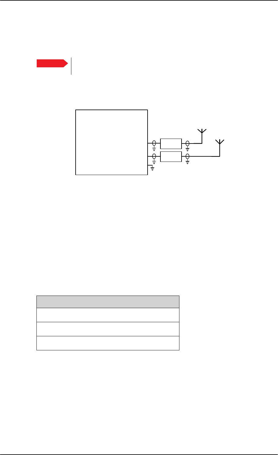
Electrical installation and wiring
5-34 Chapter 5: Installation 98-127093-H
5.3.7 Wiring WLAN antenna interface
Before wiring the WLAN antenna interface make sure that your system has the Built-in
Wireless Option TT-5040A-003.
With software 4.00 and SB-Safety voice the WLAN access point must be
disabled in the configuration software.
Overview
The following drawing shows the wiring of the SBU WLAN antenna interfaces.
Figure 5-21: Wiring WLAN antenna interfaces #1 and #2
WLAN low pass filter
The WLAN module in the SBU can in theory transmit in the 5 GHz (802.11a) frequency
range. This is inhibited permanently by the software in the SBU. If the aircraft cannot be
tested to be immune to 5 GHz signals, you can optionally insert a 2.4 GHz low pass filter
into the WLAN Coax to safeguard the aircraft against transmission in the 5 GHz frequency
range.
WLAN pins
The following list shows the pins used for the WLAN antenna interface on the SBU.
Important
77$
6%8
:/$1DQWHQQDFRD[73$
:/$1DQWHQQDFRD[73$
73
:/$1HQDEOH
:/$1DQWHQQDDQG
:
:
/RZ3DVV
)LOWHU>@
/RZ3DVV
)LOWHU>@
>@2SWLRQDO
SBU pin Name/description
TPA2 WLAN antenna #1 (coax)
TPA4 WLAN antenna #2 (coax)
TP5 WLAN Enable, Discrete Input (active low)
Table 5-18: SBU pins for WLAN antenna #1 and #2
SB-Lite.book Page 34 Tuesday, September 5, 2017 1:38 PM
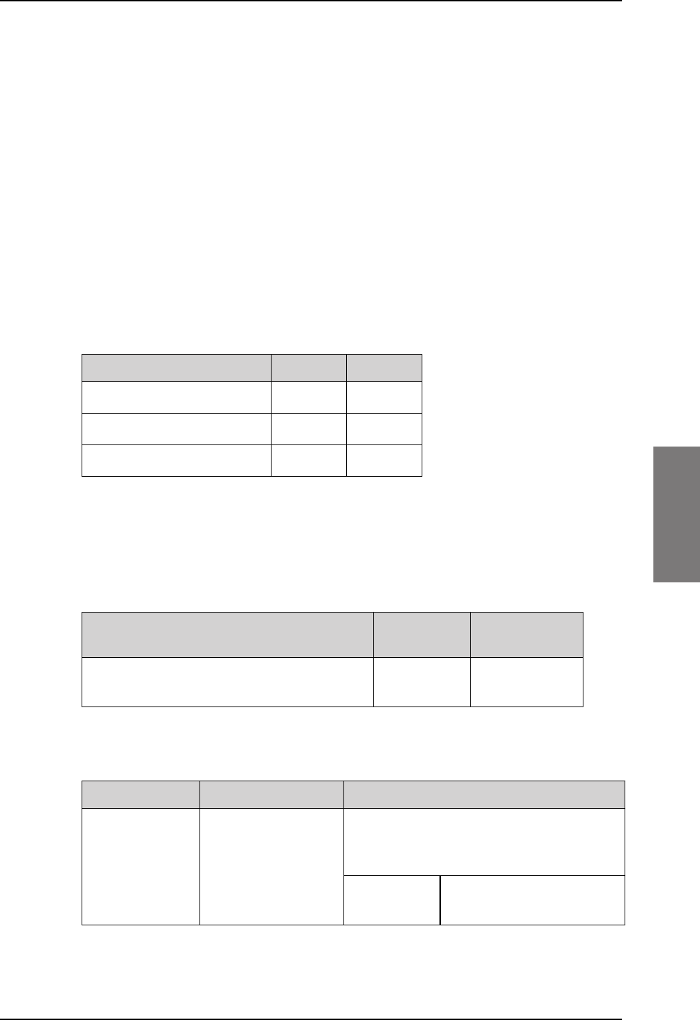
Electrical installation and wiring
98-127093-H Chapter 5: Installation 5-35
5555
Description of the WLAN interface
The WLAN interface on the SBU supports operation according to the IEEE 802.11b and
802.11g standards. The WLAN (2.4GHz) frequency band is divided into 14 channels.
Not all countries allow full use of all channels. Also, some countries do not allow operation
according to the 802.11g standard. Therefore the WLAN interface must be set up to the
right country code. For further information, see WLAN country codes on page D-1.
The maximum EIRP output level for WLAN 802.11b and 802.11g is 100 mW for indoors
use. To prevent the EIRP output power from exceeding this limit, the maximum antenna
gain must not exceed the cable loss between the antenna and the SBU.
Operating with a single WLAN antenna
If operating with a single WLAN antenna, it is recommended to use the WLAN pin TP A2.
Make sure to set up WLAN interface correctly — Antenna configuration: Main or Aux for
single antenna operation — see WLAN interface (option) on page 6-22.
Table 5-19: WLAN antenna configuration
Antenna configuration SBU TP A2 SBU TP A4
Diversity (antenna #1 and #2) TX/RX RX
Main (antenna #1) TX/RX –
Aux (antenna #2) – TX/RX
RF cable requirements for WLAN
To achieve optimal performance for the WLAN system select a cable type with a minimal
cable loss when cabling the TT5040A-004 WLAN antenna. For a table with cable types and
cable losses see Recommended RF cables on page 5-48.
Order information for low pass filter for WLAN
Cable Min. cable loss
@2.4 GHz
Max. cable loss
@2.4 GHz
From TP A2 to TT5040A-004 WLAN antenna
and TP A4 to TT5040A-004 WLAN antenna
0 dB 5 dB
Table 5-20: Cable requirements for WLAN
Product name Description Manufacturer
Coaxial Low Pass
Filter SLP-2950+
Low-pass filter for
WLAN
Mini-Circuits
P.O. Box 350166,
Brooklyn, NY 11235 U.S.A.
Phone:
Home page:
(718) 934-4500
www.minicircuits.com
Table 5-21: Low pass filter for WLAN, order information
SB-Lite.book Page 35 Tuesday, September 5, 2017 1:38 PM
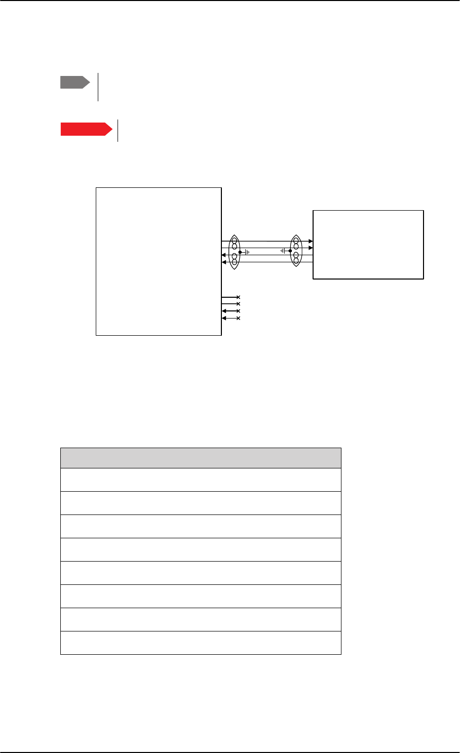
Electrical installation and wiring
5-36 Chapter 5: Installation 98-127093-H
5.3.8 Wiring ISDN
Wiring drawing
Note that even though the AVIATOR 200/300/350 system supports connection of several
ISDN devices, the satellite channel only supports transmission on one ISDN channel.
Pins for ISDN
The following lists show the pins used for the ISDN interfaces on the SBU.
Note The AVIATOR 200 does not support ISDN services. The interface can be used for
standard voice services.
Important With software 4.00 and SB-Safety voice ISDN is forced disabled.
Figure 5-22: Wiring ISDN interface
,6'1
H[WHUQDOO\
SRZHUHG7(
5-
)HPDOH&RQQHFWRU
,6'17[GRXWSXW73
,6'17[HRXWSXW73
,6'15[FLQSXW73
,6'15[ILQSXW73
77$
6%8
17
5[LQSXW
5[LQSXW
7[RXWSXW
7[RXWSXW
,6'17[FRXWSXW73
,6'17[IRXWSXW73
,6'15[GLQSXW73
,6'15[HLQSXW73
7(
'RQRWFRQQHFW
'RQRWFRQQHFW
'RQRWFRQQHFW
'RQRWFRQQHFW
SBU pin Name/description
TP23 ISDN #1 Rx+ (c) input (NT)
TP24 ISDN #1 Tx+ (d) output (NT)
TP25 ISDN #1 Tx- (e) output (NT)
TP26 ISDN #1 Rx- (f) input (NT)
TP15 ISDN #2 Tx+ (c) output (TE). Do not connect!
TP16 ISDN #2 Rx+ (d) input (TE). Do not connect!
TP17 ISDN #2 Rx- (e) input (TE). Do not connect!
TP18 ISDN #2 Tx- (f) output (TE). Do not connect!
Table 5-22: SBU pins for ISDN
SB-Lite.book Page 36 Tuesday, September 5, 2017 1:38 PM
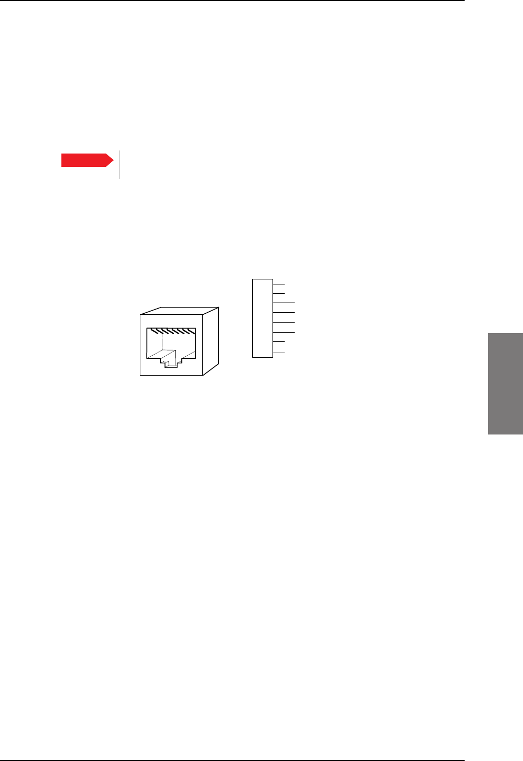
Electrical installation and wiring
98-127093-H Chapter 5: Installation 5-37
5555
Description of SBU ISDN interface
The SBU has one ISDN interface. The ISDN of the SBU uses the SwiftBroadband service.
The Euro ISDN S-bus interface is configured as the network side of the NT1 interface i.e. Rx
is an input and Tx is an output.
The ISDN interface on the SBU can address up to 8 ISDN devices. The ISDN interface
supports 56/64kbps data rate and G4 Fax on the SwiftBroadband connection. You can also
use the SBU ISDN interface to make an AMBE2 or 3.1 kHz audio call.
The SBU does not provide DC power on the ISDN interface of the SBU. All
ISDN devices connected to the SBU must be powered externally.
To be compliant with ISO8877 [2] and the ISDN connector specification defined by ITU
I.420 [6], an RJ45 Female Connector must be connected to the four-wire ISDN lines from
the SBU.
The SBU includes an internal 100 termination resistor to support cable lengths up to
100 meters (109 yards). Make sure the other end of the cable is terminated properly.
Cable requirements for ISDN
• Cable for the ISDN interface: 100 4-wire shielded cable.
• The conductors must be twisted in pairs.
• Supported cable lengths: up to 100 meters (328 feet).
5.3.9 Wiring telephone systems
Built-in Private Branch Exchange (PBX)
The built-in PBX of the SBU controls the 2-wire POTS interfaces #1 and #2 and one ISDN
interface.The built-in PBX can also route VoIP calls that are terminated in the SIP server of
the SBU.
Without the Multi-voice option the AVIATOR 200/300/350 system supports one external
call at a time. When the circuit-switched connection is in use by another phone, you have
to wait until the line if free.
VoIP calls and SIP telephony
You can use phones with a SIP client and the WLAN interface to make calls. These calls are
terminated in the SIP server of the SBU and routed through the built-in PBX on the Swift
Broadband channel. For a detailed description how to set up your phone see SIP setup for
Important
Figure 5-23: ISDN RJ45 connector
,6'15[,QSXWF
,6'17[2XWSXWG
,6'17[2XWSXWH
,6'15[,QSXWI
QRWFRQQHFWHG
5-IHPDOHFRQQHFWRU
QRWFRQQHFWHG
QRWFRQQHFWHG
QRWFRQQHFWHG
5-
IHPDOH
SB-Lite.book Page 37 Tuesday, September 5, 2017 1:38 PM

Electrical installation and wiring
5-38 Chapter 5: Installation 98-127093-H
Wifi-enabled phones on page H-1.
2-wire POTS interface #1 and #2
The 2-wire interfaces may be connected and configured to the 2-wire systems listed below:
• TT-5621B 2-Wire Handset / TT-5622B 2-Wire Cradle
• ICG DECT Cordless Handset with POTS interface
• Sigma7 phone with POTS interface
• Fax or Modem data with POTS interface
• Headset interface box PTA-12 Airborne telephone adapter
• Secure devices with POTS interface (STU/FNBDT)
The maximum number of telephones on each 2-wire POTS interface is:
Two TT-5621B 2-Wire Handset / TT-5622B 2-Wire Cradle or two Sigma7 phones.
Note that the AVIATOR 200/300/350 system supports one external call at a time. When
one phone is in use, you cannot use the other phone on the same 2-wire POTS interface.
ISDN interface
The ISDN interface on the SBU may be used with an ISDN phone or fax machine and/or an
ISDN data modem. A maximum of 8 ISDN units (ISDN phones, ISDN fax or ISDN data
modem) may be connected to the ISDN interface, but only one unit may be active at a
time. Secure device is supported with ISDN interface (STE).
Configuration of wired handset interfaces
The following drawing shows the possible combinations of devices connected to the
handset interfaces.
Important With software 4.00 and SB-Safety voice, the 2-wire POTS interface #2 is
forced disabled.
Important With software 4.00 and SB-Safety voice, the ISDN interface is forced
disabled.
SB-Lite.book Page 38 Tuesday, September 5, 2017 1:38 PM
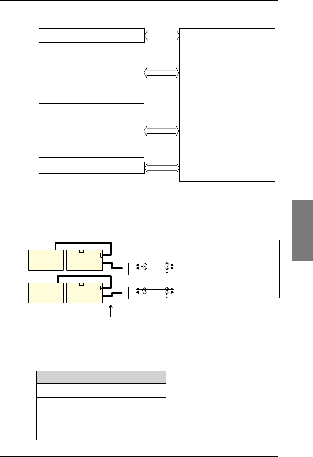
Electrical installation and wiring
98-127093-H Chapter 5: Installation 5-39
5555
Wiring 2-Wire Handsets
The following drawing shows the wiring of the TT-5621B 2-Wire Handset / TT-5622B 2-
Wire Cradle.
Pins for 2-wire interfaces
The below lists show the pins used for the 2-wire interfaces of the SBU.
Table 5-23: SBU pins for 2-Wire interface
TP6 2-Wire Voice/Fax/Modem #1 (Ring)
TP7 2-Wire Voice/Fax/Modem #2 (Ring)
TP11 2-Wire Voice/Fax/Modem #1 (Tip)
TP12 2-Wire Voice/Fax/Modem #2 (Tip)
Figure 5-24: Handset interfaces with possible combinations of connected devices.
77$6%8
3ULYDWH%UDQFK([FKDQJH
3%;ZLWK6,3VHUYHU
,6'1
,6'1GHYLFHVZLWKH[WHUQDOSRZHU67( ,6'1LQWHUIDFH
ZLUH3276
2QHRIWKHIROORZLQJ
77%:LUH+DQGVHWZLWK77%
:LUH&UDGOH
,&*'(&7&RUGOHVV+DQGVHW
6LJPD3KRQH
)$;
0RGHP
37$
ZLUHLQWHUIDFH
ZLUH3276 ZLUHLQWHUIDFH
2QHRIWKHIROORZLQJ
77%:LUH+DQGVHWZLWK77%
:LUH&UDGOH
,&*'(&7&RUGOHVV+DQGVHW
6LJPD3KRQH
)$;
0RGHP
37$
9R,36,3 :/$1LQWHUIDFH
:/$1HQDEOHG6,3WHOHSKRQH
Figure 5-25: Wiring T&T 2-Wire Handset systems
77%
:LUH&UDGOH
77%
:LUH&UDGOH
77%
:LUH+DQGVHW
77%
:LUH+DQGVHW
1RWHVKRUWFDEOHZLWK6XE'
FRQQHFWRULVPRXQWHGRQHDFKFUDGOH
77$
6%8
ZLUHID[PRGHP
ZLUHID[PRGHP
'%)'%0
'%0 '%) 73
73
7LS
5LQJ ZLUH9RLFH)D[0RGHP
73
73
7LS
5LQJ ZLUH9RLFH)D[0RGHP
5-
5-
FDEOH
FDEOH
SBU pin Name/Description
SB-Lite.book Page 39 Tuesday, September 5, 2017 1:38 PM
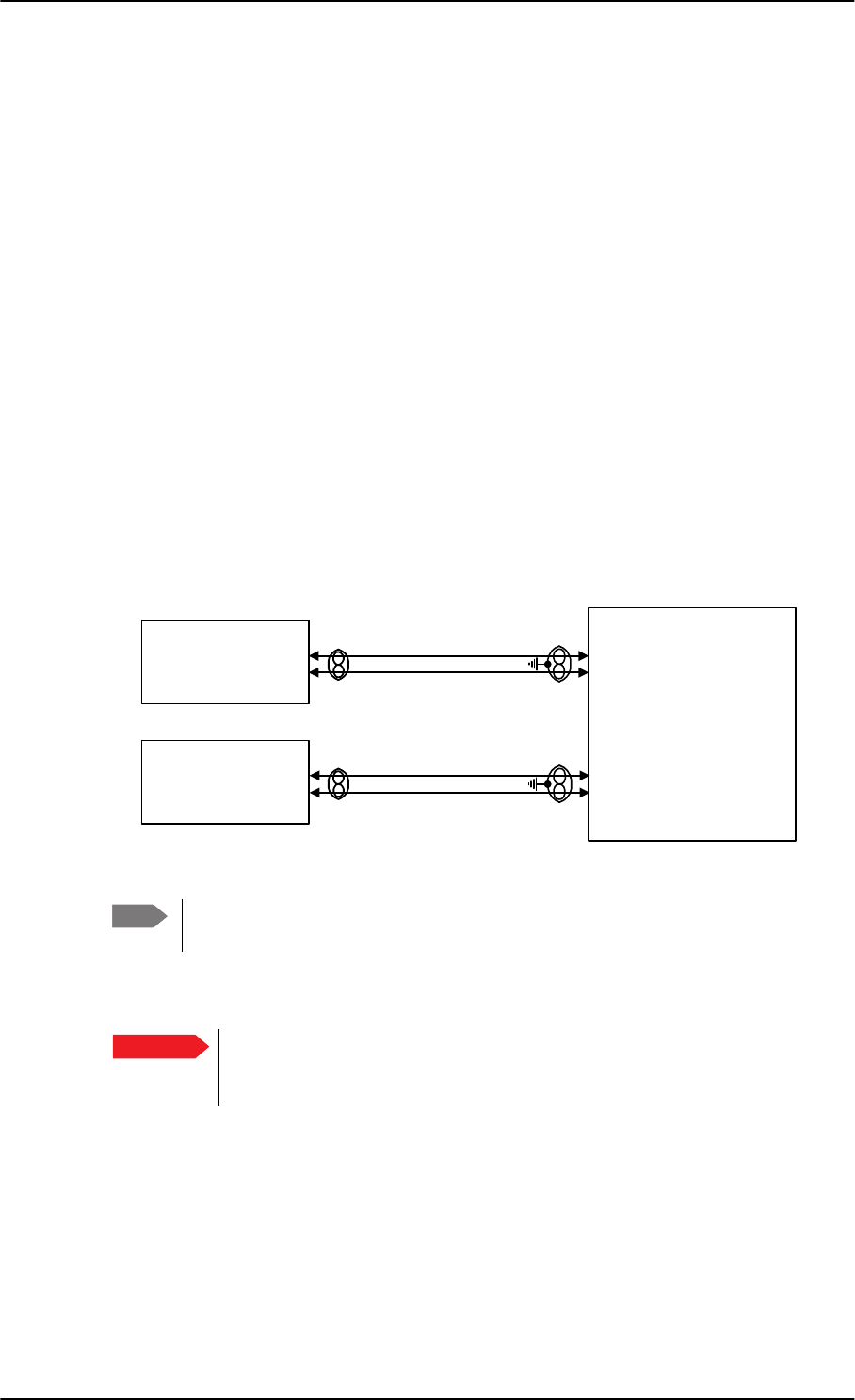
Electrical installation and wiring
5-40 Chapter 5: Installation 98-127093-H
Description of 2-wire interfaces #1 and #2
The SBU has two 2-wire Voice/Fax/Modem POTS interfaces connected to the PBX. The
interfaces comply with 2-wire 600 standard US DTMF telephones. The 2-wire interfaces
are not galvanically isolated from the aircraft frame. Galvanic isolation is required at the
external 2-wire terminal.
Two TT-5621B 2-Wire Handset phones can be connected in parallel on each interface.
These interfaces are used for the TT-5621B/ TT-5622B Thrane & Thrane aeronautical
handset system, but may also be used for e.g. the Sigma7, ICG DECT Cordless Handset
phones, fax, modem or secure devices and PTA-12.
For information on wiring of Sigma7 phones, see Wiring Sigma7 (2-wire) handsets on
page 5-40. For information on wiring of ICG DECT Cordless Handset phones, see Wiring
ICG DECT Cordless Handset (2-wire) phone on page 5-41.
Supported cable length: 100 meters (328 feet)
5.3.10 Wiring Sigma7 (2-wire) handsets
One or two Sigma7 handsets can be connected to the 2-wire interfaces of the
AVIATOR 200/300/350 system. The following drawing shows the wiring of Sigma7
handsets.
Figure 5-26: Wiring Sigma7 handsets
The above wiring shows the connection for the non-backlit Sigma7 handset. The
backlit version Sigma7 handset uses pin 6 for Tip 1 and pin 3 for Ring 1.
Connect J1 on the Sigma7 handset to the rear receptacle of the SBU according to the wiring
drawing above.
In order for the volume in the Sigma7 handset to be sufficient, it is normally
necessary to adjust the “ear volume” using the menu system of the handset.
For information on how to do this, see Sigma7 setup on page 6-99.
For information on the 2-wire interface, see Pins for 2-wire interfaces on page 5-39.
Note
Important
:,5()$;02'(03276
6LJPD
&UDGOH
:,5()$;02'(03276
77$
6%8
73
73
73
73
-SLQ
-SLQ
6LJPD
&UDGOH
-SLQ
-SLQ
+DQGVHW,QWHUIDFH
+DQGVHW,QWHUIDFH
SB-Lite.book Page 40 Tuesday, September 5, 2017 1:38 PM
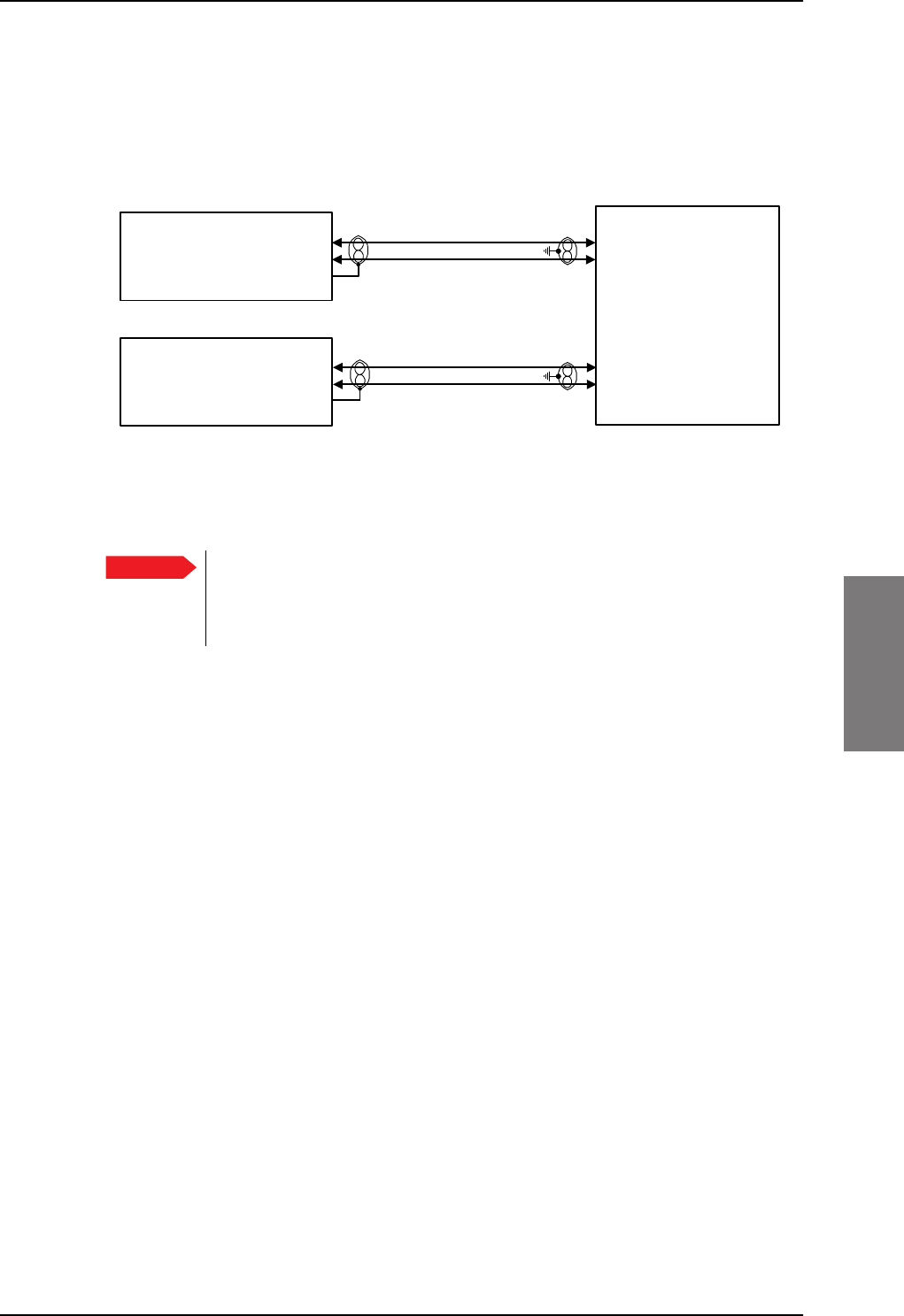
Electrical installation and wiring
98-127093-H Chapter 5: Installation 5-41
5555
5.3.11 Wiring ICG DECT Cordless Handset (2-wire) phone
One or two ICG DECT Cordless Handset phones can be connected to the 2-wire interfaces
of the AVIATOR 200/300/350 system. The following drawing shows the wiring of ICG
DECT Cordless Handset 2-wire phones.
Connect J2 on the base station of the ICG DECT Cordless Handset phone to the rear
receptacle of the SBU according to the wiring drawing above. The base station is supplied
together with the handset and cradle.
In order for the ICG DECT Cordless Handset phone to work properly, it is
normally necessary to make a few initial adjustments of the handset. For
information on how to do this, see ICG DECT Cordless Handset setup on
page 6-99.
For information on the 2-wire interface, see Pins for 2-wire interfaces on page 5-39.
Figure 5-27: Wiring ICG DECT Cordless Handset handsets
Important
:,5()$;02'(03276
*+]&RUGOHVV
%DVH8QLW
:,5()$;02'(03276
77$
6%8
73
73
73
73
-SLQ
-SLQ
-SLQ
*+]&RUGOHVV
%DVH8QLW
-SLQ
-SLQ
-SLQ
+DQGVHW,QWHUIDFH
+DQGVHW,QWHUIDFH
SB-Lite.book Page 41 Tuesday, September 5, 2017 1:38 PM
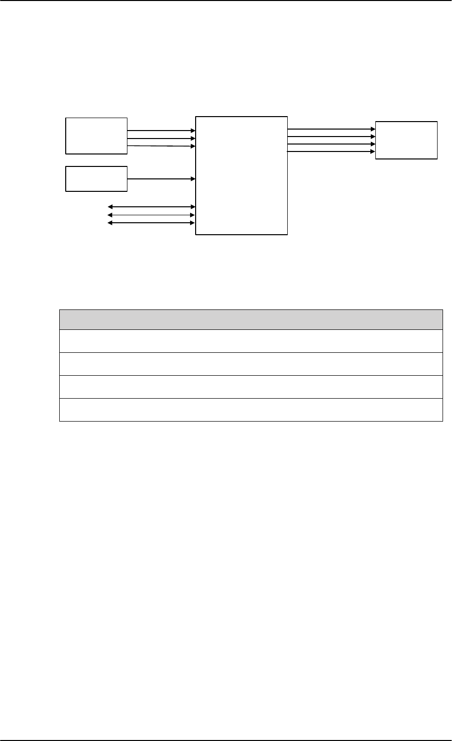
Electrical installation and wiring
5-42 Chapter 5: Installation 98-127093-H
5.3.12 Wiring discretes
Discrete annunciators and Chime/Lamps Inhibit
The following drawing shows the wiring of discrete annunciators and Chime/Lamps Inhibit.
Pins for discrete annunciators
The following list shows the pins used for discrete annunciators:
Table 5-24: SBU pins for discrete annunciators
TP27 Annunciator #3 “Service available” (Discrete I/O) Output: Lamp Driver
TP28 Annunciator #1 “Incoming call” (Discrete I/O) Output: Lamp Driver
TP29 Annunciator #2 “SBU failed” (Discrete I/O) Output: Lamp Driver
BP1 Annunciator #4 “Message received” (Discrete I/O) Output: Lamp Driver
Function of discrete annunciators
The function of the annunciators is as follows:
• Annunciator #1 “Incoming call” (TP28)
Default behavior: Active (low) when a handset is ringing.
• Annunciator #2 “SBU Failed” (TP29).
Default behavior: Active (low) whenever a BITE with severity essential or fatal is active
on the SBU.
• Annunciator #3 “Service available” (TP27).
Default behavior: Active (low) when the SwiftBroadband Service is available.
• Annunciator #4 “Message received” (BP1).
Default behavior: Active (low) when a Message is received in the SBU.
Figure 5-28: Wiring discretes
$QQXQFLDWRU
77$
6%8
'LVFUHWH
,QSXWV
6%8(QDEOH
:/$1(QDEOH
6%8Q2Q 73
73
73
$QQXQFLDWRUV
$QQXQFLDWRU
$QQXQFLDWRU
$QQXQFLDWRU
73
73
73
%3
73
&KLPH/DPSV,QKLELW
&KLPH/DPSV
,QKLELW
6SDUH,2
6SDUH,2 %3
%3
73
6SDUH,2
SBU pin Name and description Discrete typea
a. The discrete interfaces are described in Description of the discrete types on page 5-44.
SB-Lite.book Page 42 Tuesday, September 5, 2017 1:38 PM
Electrical installation and wiring
98-127093-H Chapter 5: Installation 5-43
5555
Pins for Chime/Lamps Inhibit input
Pins used for the Chime/Lamps Inhibit input:
Description of the Chime/Lamps Inhibit interfaces
The SBU has one discrete input for the Chime/Lamps Inhibit function. This input is used to
inhibit Satcom activation of the chime and call lights during take-off and landing. The
Inhibit function is activated by connecting this input to ground.
Polarity of the discrete annunciators and Chime/Lamps Inhibit input
In the web interface you can change the polarity of the discrete annunciators and the
Chime/Lamps Inhibit input from Active low (default) to Active high. For instructions how to
do this see Configure the discrete I/O interfaces on page 6-37.
Pins for non-configurable discrete inputs on the SBU
The SBU has two non-configurable discrete inputs: one for SBU nON, one for WLAN Enable.
The below table shows the pin-out for the discrete inputs:
SBU nON (TP3): The SBU nON input is used to power the SBU on and off. Connect this
input to ground to turn on the SBU. The electrical specification is defined in Description of
the discrete types below.
SBU Enable (TP8): The SBU Enable discrete input is active low and must be connected to
ground. The input is used to inhibit the transmitter output signal and to reset the SBU, when
the input is released to either open circuit or to high state. When pulled low the SBU is
enabled (active). The electrical specification is defined in the following section, Description
of the discrete types.
WLAN Enable (TP5): WLAN Enable input is used to enable the WLAN interface. The input
is active low and the WLAN interface is kept disabled and reset as long as the input is at the
high state. When the input is connected to ground or to low state the WLAN interface will
be initialized and ready for use. When the WLAN interface is not enabled no RF is emitted
from the interface.
SBU pin Name/description Specification of discrete type
TP13 Chime/Lamps Inhibit Discrete input (default: active low)
Table 5-25: SBU pin for Chime/Lamps Inhibit input
SBU pin Name/description
TP3 SBU nON input
TP8 SBU Enable input
TP5 WLAN Enable input
Table 5-26: SBU pins for discrete inputs
SB-Lite.book Page 43 Tuesday, September 5, 2017 1:38 PM
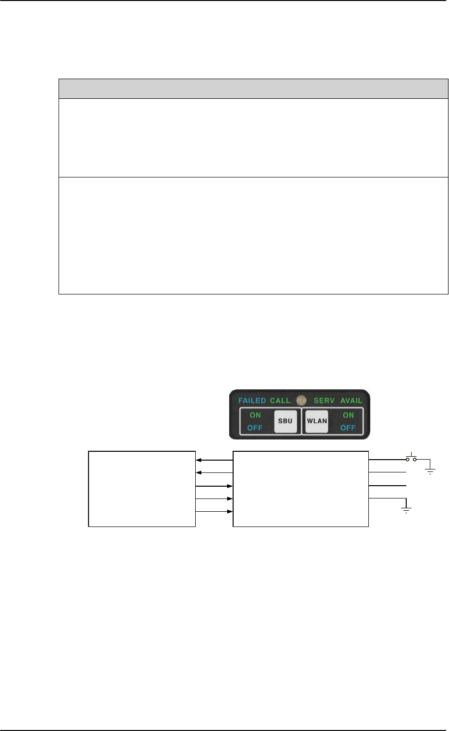
Electrical installation and wiring
5-44 Chapter 5: Installation 98-127093-H
Description of the discrete types
Discrete type and description:
5.3.13 Wiring the Switch Annunciator Panel
The following drawing shows the wiring of discrete inputs/annunciators and the Switch
Annunciator Panel MD-41-1948.
Figure 5-29: Wiring the Switch Annunciator Panel MD-41-1948
Discrete type Description
Lamp Driver The output configuration forms a switch closure to ground. The
electrical specification for the Lamp type switch is:
Open switch hold-off voltage: max. +39.5 V DC
Closed switch voltage: max. 1 V DC at 500 mA
Open switch resistance (OFF): min. 100 k
Discrete input The discrete input detects the following states:
“Open” voltage: 7 V DC to 39.5 V DC or 100 k to ground.
“Short” voltage: 0 ±3.5 V DC or 1500 to ground.
Input characteristics:
Reaction time: <500 ms.
The internal interface is diode-isolated for parallel connection
externally to any other LRU(s), with at least 200 k of isolation, when
power is not applied.
Table 5-27: Specification of discrete types
77$
6%8
6%8Q2173
:/$1HQDEOH73
6HUYLFHDYDLODEOH73
,QFRPLQJFDOO73
6%8IDLOHG73
0'
6ZLWFK
$QQXQFLDWRU
3DQHO
6%8RQRII
:/$1RQRII
6(59$9$,/
&$//
)$,/
/DPS7HVW
9'&3RZHU
9'LPPHULQ
*URXQG
SB-Lite.book Page 44 Tuesday, September 5, 2017 1:38 PM
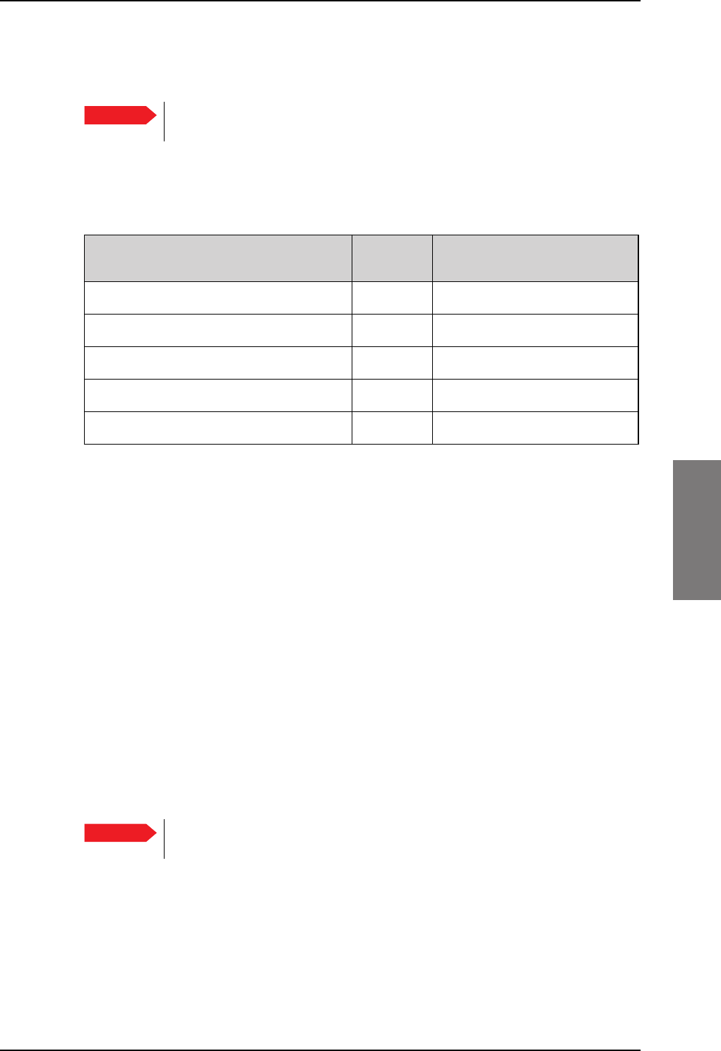
Electrical installation and wiring
98-127093-H Chapter 5: Installation 5-45
5555
5.3.14 Wiring an SB-Safety Voice Annunciator Panel
The SBU can be connected to an SB-Safety Voice Annunciator Panel. This panel then shows
the SB-Safety call status, that is priority and an SB-Safety Voice fail button. The pins for
connecting the panel are located in the top plug (TP) and the bottom plug (BP) of the SBU
rear receptacle. To connect such a panel see the following table.
Table 5-28: SBU pins for discrete inputs
TP14 Lamp for priority 1 Active low Spare I/O
BP4 Lamp for priority 2 Active low Spare I/O
BP2 Lamp for priority 3 Active low Spare I/O
TP28 Lamp for SB-Safety Voice call Active low Incoming call
TP27 Lamp for SB-Safety Voice fail Active high Service availablea
a. When SB-Safety Voice is not enabled, this output is an indicator for Service Available which
shows the availability on either PS or CS connections. When SB-Safety Voice is enabled, SB-
Safety Voice Fail is indicated after manually changing the polarity through configuration in
the web interface to Active high. Note that there is no visual indication on fail of the PS
availability when SB-Safety Voice is enabled, the output only shows the availability of a CS
connection. If also ACARS is installed, you can find this information via the ACARS pages on
the MCDU.
Chime/Lamps Inhibit discrete input behavior with SB-Safety Voice
You can use the Chime/Lamps Inhibit discrete input (TP13, default: active low) to control
the chime signals. When this input is active, the following is affected:
• The Call indicator will not indicate an incoming call.
• There will be no ring signal on the POTS interface on an incoming call. However the
priority indicator will flash and the call can be answered as normal.
5.3.15 Wiring the maintenance interface
Maintenance PC and ATE
The following drawing shows the wiring of:
• the LAN Maintenance PC connection on the SBU,
• ATE interface (for factory use only - do not connect!)
Important To use this feature the SBU must have software 4.00 and CMU/ACARS/SB-
Safety voice option.
SBU pin Name/description Polarity Use without SB-Safety Voice
service
Important Make sure that there is no cable connected to the SBU Maintenance
connector when the aircraft is airborne.
SB-Lite.book Page 45 Tuesday, September 5, 2017 1:38 PM
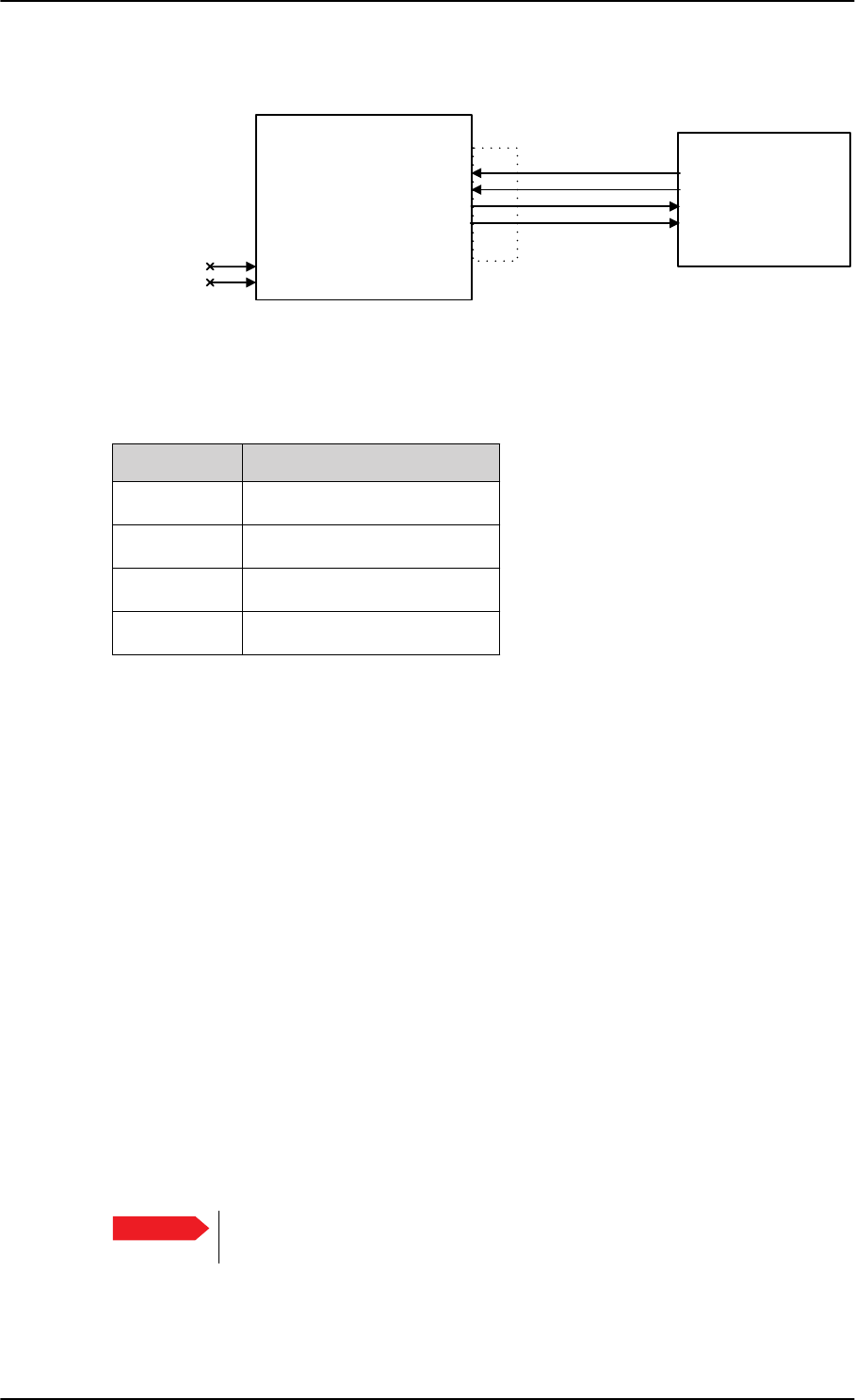
Electrical installation and wiring
5-46 Chapter 5: Installation 98-127093-H
Pins for the Maintenance interface on SBU
The following list shows the pins used for the Maintenance interface on the SBU.
Description of the Maintenance interface on the SBU
Use the Maintenance interface on the front of the SBU for configuration and maintenance
purpose, i.e. for tasks like configuring RF cable settings for the installation, satcom antenna
setup, navigational input and software upgrades.
The interface is a 10/100BaseT Ethernet and can be accessed from a PC with Ethernet
interface. The PC is connected using a standard straight network cable.
The maintenance interface has the following characteristics:
• 100 Base-T /10 Base-T Ethernet
• IEEE 802.3
To access the configuration settings, use a PC with a browser and open the built-in web
interface of the SBU. For further information, see Configuration tasks on page 6-2.
Pins for Automatic Test Equipment (ATE)
The SBU has two pins for Automatic Test Equipment (ATE): ATE #1 (TP9) and ATE #2
(TP10). The ATE pins are for factory use only.
Figure 5-30: Wiring Maintenance PC and Reset
77$
6%8
73$7(
73$7(
)3
)3
)3
)3
0DLQWHQDQFH
3&
0DLQWHQDQFH
FRQQHFWRU
5-
5['
5['
7['
7['
5-
)RUIDFWRU\XVHRQO\
'RQRWFRQQHFW
SBU pin Name/Description
FP1 TxD+
FP2 TxD-
FP3 RxD+
FP6 RxD-
Table 5-29: SBU pins for Maintenance interface
Important Do not connect anything to the ATE pins, not even ground! Connecting
the ATE pins can cause unintended function of the system.
SB-Lite.book Page 46 Tuesday, September 5, 2017 1:38 PM
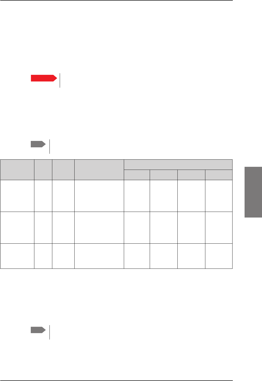
Recommended cables
98-127093-H Chapter 5: Installation 5-47
5555
5.4 Recommended cables
5.4.1 Introduction
This section lists recommended cables and allowed cable lengths for the cables in the
AVIATOR 200/300/350 system.
5.4.2 Power cables, allowed cable lengths
Allowed cable lengths, SBU
The following table shows the allowed SBU cable lengths for selected AWG types. If other
AWG types are used, make sure the contact type supports the AWG type.
It is generally recommended to keep cable lengths as short as possible, specially
on cables for Chassis GND.
Allowed cable lengths, HLD
The following table shows the allowed HLD cable lengths for selected AWG types. If other
AWG types are used, make sure the contact type supports the AWG type.
It is generally recommended to keep the Chassis GND cable lengths as short as
possible.
Important For specific requirements to the cables, see the applicable section in
5.3 Electrical installation and wiring.
Note
Description Pin Contact
type Max. resistance Max length (at 70C)
AWG20 AWG18 AWG16 AWG14
SBU
+28 V DC
Power
TP1 16 210 m a
(250 m-40 m in
7.5 A circuit
breaker)
a. The max. cable resistance is calculated using the resistance of a Klixon 2TC circuit breaker. If another circuit
breaker is used, the max. resistance and cable length may differ from these values.
17 fta
(5.2 m)
27 fta
(8.3 m)
43 fta
(13.2 m)
(not suitable
for this
contact size)
SBU
GND, Power
Return
TP2 16 25 m
The cable should be
as short as possible,
max. 1 m.
2 ft
(0.6 m)
3 ft
(0.9 m)
5 ft
(1.5 m)
(not suitable
for this
contact size)
SBU Chassis
Ground
BP3 16 25 m
Connect directly to
aircraft chassis.
2 ft
(0.6 m)
3 ft
(0.9 m)
3.3 ft
(1.0 m)
(not suitable
for this
contact size)
Table 5-30: Allowed lengths for SBU power cables
Note
SB-Lite.book Page 47 Tuesday, September 5, 2017 1:38 PM
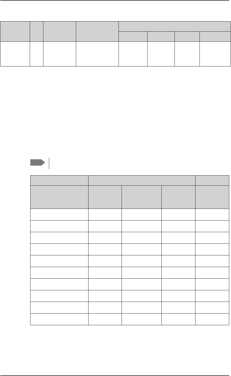
Recommended cables
5-48 Chapter 5: Installation 98-127093-H
5.4.3 Recommended Power cables
The cable types shall meet the following standards:
• M27500 for shielded wire.
• M22759 for single wire.
5.4.4 Recommended RF cables
The following cable types are recommended for the RF cables. Contact your cable supplier
for other cable types.
Equivalent cable types, which meet the requirements, may also be used.
Description Pin Contact type Max. resistance Max length (at 70C)
AWG20 AWG18 AWG16 AWG14
HLD
Chassis
Ground
X4 M5 threaded
stud
25 m
(additional req.:
max. length 1 m)
2 ft
(0.6 m)
3 ft
(0.9 m)
3.3 ft
(1.0 m)
(not suitable
for this contact
size)
Table 5-31: Allowed lengths for HLD Chassis Ground cable
Note
CABLE TYPE SPECIFICATIONS
Part number Diameter
(mm/in.)
Minimum Bend
Radius (mm/ in.)
Attenuation
(dB/100ft)
@ 1.6 GHz
Size 5
contact part
number
ECS 3C142B 4.95/0.19 25.4/1.0 18.1 620021
PIC S22089 11.0/0.43 63.5 / 2.5 4.8 n.a.
PIC S33141 6.9/0.27 35.6 / 1.4 8.6 n.a.
ECS 310801 11.48/0.452 57.4 / 2.26 4.6 n.a.
ECS 311201 8.05/0.317 40.6 / 1.6 6.7 n.a.
ECS 311501 5.82/0.229 30.5 / 1.2 9.1 P922
EMTEQ TFLX165-100 4.19/0.17 21.6 / 0.85 16.8 A45165-1
EMTEQ PFLX195-500 5.08/0.2 12.7/0.5 14.0 A45195-1
EMTEQ TFLX295-100 7.95/0.31 40.6 / 1.6 7.6 n.a.
EMTEQ TFLX480-100 12.2/0.48 57.2 / 2.25 4.8 n.a.
Table 5-32: List of Recommended RF Cables
SB-Lite.book Page 48 Tuesday, September 5, 2017 1:38 PM
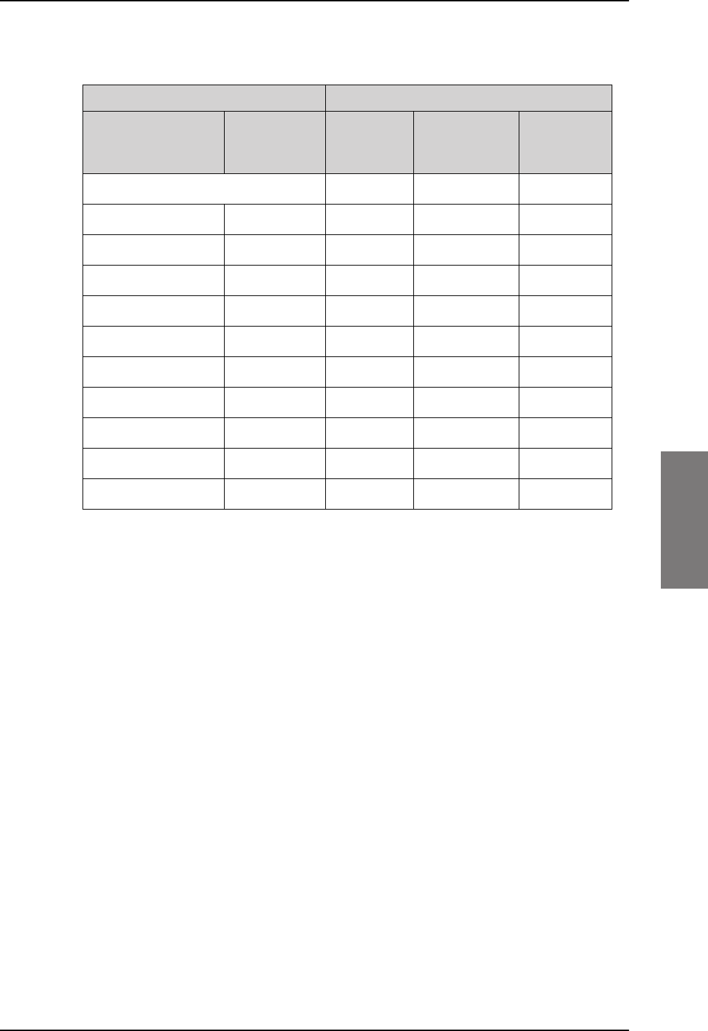
Recommended cables
98-127093-H Chapter 5: Installation 5-49
5555
Maximum cable lengths for WLAN cables
5.4.5 Recommended cables for ARINC 429
Use ARINC 429 cables that meet the following standard:
• M27500 for shielded wire
The cables for the ARINC 429 interfaces must be twisted and shielded and conform to the
standards for aeronautical use.
5.4.6 Recommended cables for Ethernet
Cables for Ethernet on SBU (Quadrax connectors)
Use an Ethernet cable that meets one of the following standards:
• TIA/EIA568-A CAT5 Requirements
• FAR 25.869(a)
The following cable types meet the requirements:
• Part number: 422404, Quadrax 24 Awg from ECS
• Part number: F 4704-4 from Draka Fileca
Cable from SBU to WLAN antenna W5 and W6 a
a. W5 and W6 stand for the cables needed when wiring the TT-5040A SBU, see Wiring
WLAN antenna interface on page 5-34.
Part number
Cable
diameter
(mm/in.)
Attenuation
(dB/100 ft)
Maximum
cable
length
Size 5
contact
part number
RF specification @2.4 GHz: 5 dB
PIC S22089 11.0/0.43 6.7 dB 75 ft (23 m) n.a.
PIC S33141 6.9/0.27 11.0 dB 46 ft (14 m) n.a.
ECS 3C142B 4.95/0.19 22.2 dB 22 ft (6 m) 620021
ECS 310801 11.48/0.452 6.5 dB 75 ft (23 m) n.a.
ECS 311201 8.05/0.317 8.9 dB 56 ft (17 m) n.a.
ECS 311501 5.82/0.229 10.7 dB 46 ft (14 m) P922
EMTEQ PFLX195-500 5.08/0.2 16.81 30 ft (9 m) A45195-1
EMTEQ TFLX165 100 4.19/0.17 21.16 dB 23 ft (7 m) A45165-1
EMTEQ TFLX295 100 7.95/0.31 9.8 dB 52 ft (16 m) n.a.
EMTEQ TFLX480 100 12.2/0.48 5.8 dB 85 ft (26 m) n.a.
Table 5-33: Allowed lengths for WLAN cables
SB-Lite.book Page 49 Tuesday, September 5, 2017 1:38 PM

Activation of airtime services
5-50 Chapter 5: Installation 98-127093-H
5.4.7 Cables for Discrete Signals
Use cables for discrete wiring that meet the following standard:
• M27500 for shielded wire
5.5 Activation of airtime services
Before the AVIATOR 200/300/350 system becomes operational, the aircraft owner or
operator must settle a contract with an Inmarsat Service Provider (ISP) so the system can
be activated. The airtime provider handles terminal activation, billing and technical support
that is related to the communication network.
The activation process may take some time, so to make sure it is ready in time, start the
activation procedure some time before the installation on the aircraft begins.
SwiftBroadband
The AVIATOR 200/300/350 system is delivered with the SIM card permanently installed in
the CM of the SBU, but not activated. The SIM card is pre-authenticated by Inmarsat and
identified by its unique IMSI number (International Mobile Subscriber Identity). The IMSI is
usually 15 digits long.
The IMSI number is printed on the part number label of the CM. It is also printed
on the Certificate of Conformity letter belonging to the CM.
You need the IMSI to activate the Satellite communication service.
For details how to activate the SIM card please contact your airtime Provider.
The contract for SwiftBroadband services with your airtime provider contains among other
items the following phone numbers and identifiers:
• Direct phone number that is associated with the IMSI number of the installation.
Typically the service provider provisions the SIM card automatically to open up for the
circuit-switched and packet switched services.
To use the packet switched services you may have to enter the APN (Access Point
Name), make sure that you have received this information from your service
provider.
For step-by-step instructions how to enter the APN see Set the common interface
settings on page 6-27.
Making calls and using the Internet
For information on how to make a call to and from the system or go on the Internet etc. see
the User Manual (part number: 98-127719).
Service providers
You find a list of Service providers on Inmarsat’s web site, Partner search
(http://www.inmarsat.com/partners/search-for-partner/).
Note
Note
SB-Lite.book Page 50 Tuesday, September 5, 2017 1:38 PM

Activation of airtime services
98-127093-H Chapter 5: Installation 5-51
5555
To retrieve the SIM card ID (IMSI)
With the system you receive the IMSI number of the SIM card that is installed in the
Configuration Module of your AVIATOR system.
The SIM card is permanently installed in the CM of the SBU. Do not take out
and replace the SIM card.
You can read out the IMSI number from the web interface that is used to configure and
control the AVIATOR system. It is listed on the page Dashboard. You can also retrieve the
IMSI number in the diagnostic report that the system can generate. For instructions how to
access the web interface see Tool for setup and use: Built-in web interface on page 6-6.
For instructions how to generate a diagnostic report see under Initial troubleshooting on
page 7-18.
The IMSI number is also printed on the part number label of the CM.
Important
Note
SB-Lite.book Page 51 Tuesday, September 5, 2017 1:38 PM

Activation of airtime services
5-52 Chapter 5: Installation 98-127093-H
SB-Lite.book Page 52 Tuesday, September 5, 2017 1:38 PM
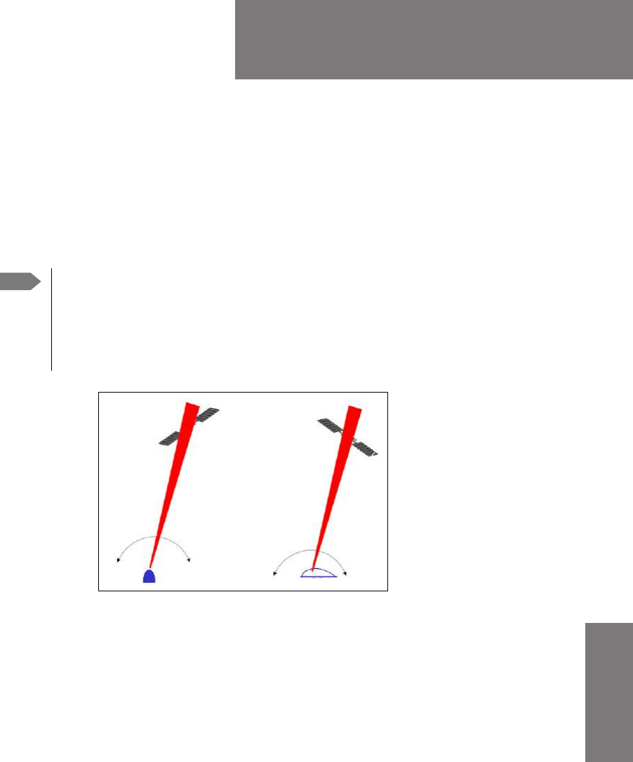
98-127093-H 6-1
Chapter 6
6666
Configuration of the
AVIATOR 200/300/350 system 6
This chapter has the following sections:
•Configuration tasks
•Tool for setup and use: Built-in web interface
•The Dashboard
•The phone book
•To set up the interfaces
•SB-Safety Voice (option)
•LAN/WLAN network users
•Administration
•Site map
•Configuration of 3rd party phone systems
•AVIATOR 200/300/350 system ready for use
Note Line of sight during operation
You can configure the system while the aircraft is in the hangar. Note that you
cannot typically check the satellite communication while the aircraft is still in the
hangar. There must be a line of sight between the Satcom antenna and the
satellite in order to use the satellite service.
Figure 6-1: Line of sight when communicating with the satellite
Satcom Antenna
SB-Lite.book Page 1 Tuesday, September 5, 2017 1:38 PM
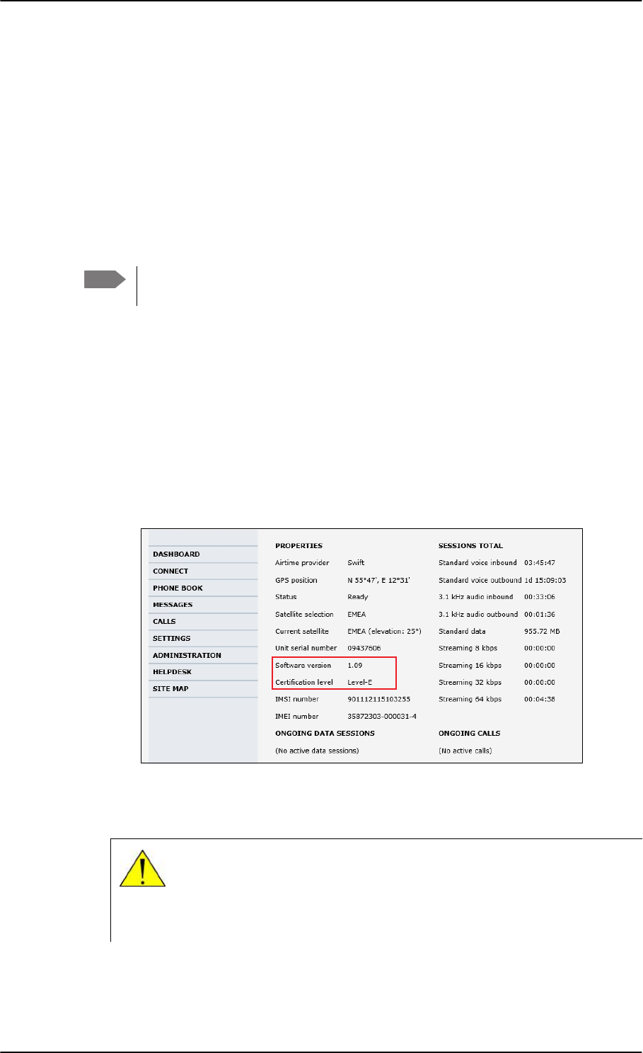
Configuration tasks
6-2 Chapter 6: Configuration of the AVIATOR 200/300/350 system 98-127093-H
6.1 Configuration tasks
Having installed the AVIATOR 200/300/350 System you must configure the
SwiftBroadband Unit properly for use with the current antenna setup, including cable losses
for the installation, and select the correct navigational input. Furthermore the interfaces
have to be set up and configured to the specific aircraft installation and application
requirements. IP connections, network user groups and profiles for IP data usage including
LAN/WLAN network management must be configured so the required applications run
smoothly on the system. For this purpose you use the built-in web interface of the
AVIATOR system.
6.1.1 Basic configuration of the SBU
As a minimum, you need to set up the following parameters in the built-in web interface of
the SBU:
1. On the DASHBOARD verify that you have the latest SBU software version (see
cobham.com/satcom, Service and support). Verify also that the certification level is
correct (Level-D or Level-E). For more information on the individual fields see The
Dashboard on page 6-12.
Figure 6-2: Basic configuration of the SBU (AVIATOR 300 example), step 1/6
2. In SETTINGS > System type, select your AVIATOR system and click Apply.
Note Before you start configuring the SBU make sure that the Configuration Module is
mounted in the SwiftBroadband Unit.
CAUTION! Selecting a wrong system type may cause damage to the
satcom antenna or GPS antenna. If the system type purchased can not be
selected, please contact the supplier of your AVIATOR 200/300/350
system.
Do not try to use a different system type!
SB-Lite.book Page 2 Tuesday, September 5, 2017 1:38 PM
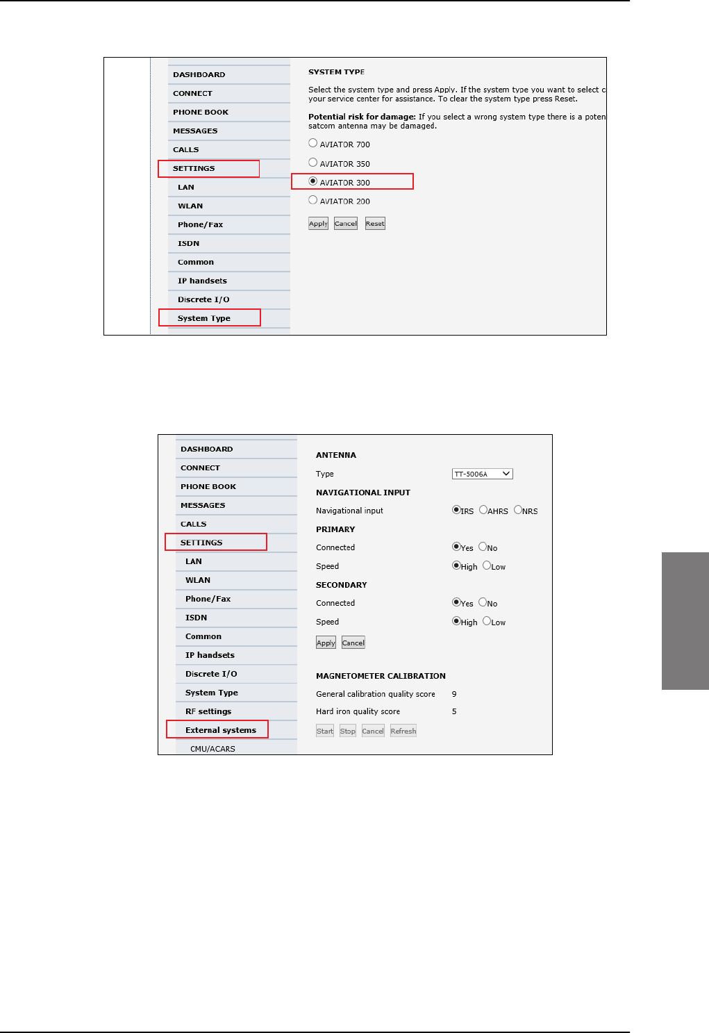
Figure 6-4: Basic configuration of the SBU, step 2/6
Configuration tasks
98-127093-H Chapter 6: Configuration of the AVIATOR 200/300/350 system 6-3
6666
For SBU software version 4.00 and SB-Safety voice flex key enabled see page 6-56.
3. In SETTINGS > External systems enter the values for Navigational input. For
detailed instructions see Set up the navigational input on page 6-44.
Figure 6-5: Basic configuration of the SBU, step 3/6
4. In SETTINGS > RF settings, enter the cable losses applicable to the SBU. For detailed
instructions see Configure RF settings on page 6-43.
1
2
3
1
2
SB-Lite.book Page 3 Tuesday, September 5, 2017 1:38 PM
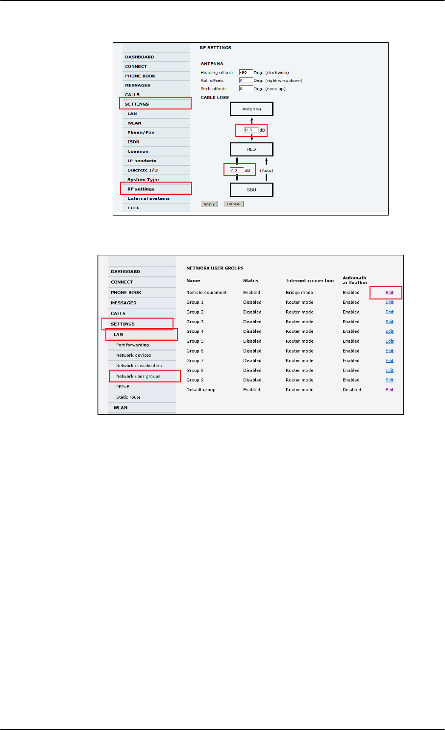
Configuration tasks
6-4 Chapter 6: Configuration of the AVIATOR 200/300/350 system 98-127093-H
5. In SETTINGS > LAN > Network user groups, click Edit.
Figure 6-7: Basic configuration of the SBU, step 5/6
1
Figure 6-6: Basic configuration of the SBU, step 4/6
1
2
3
4
1
2
4
3
SB-Lite.book Page 4 Tuesday, September 5, 2017 1:38 PM
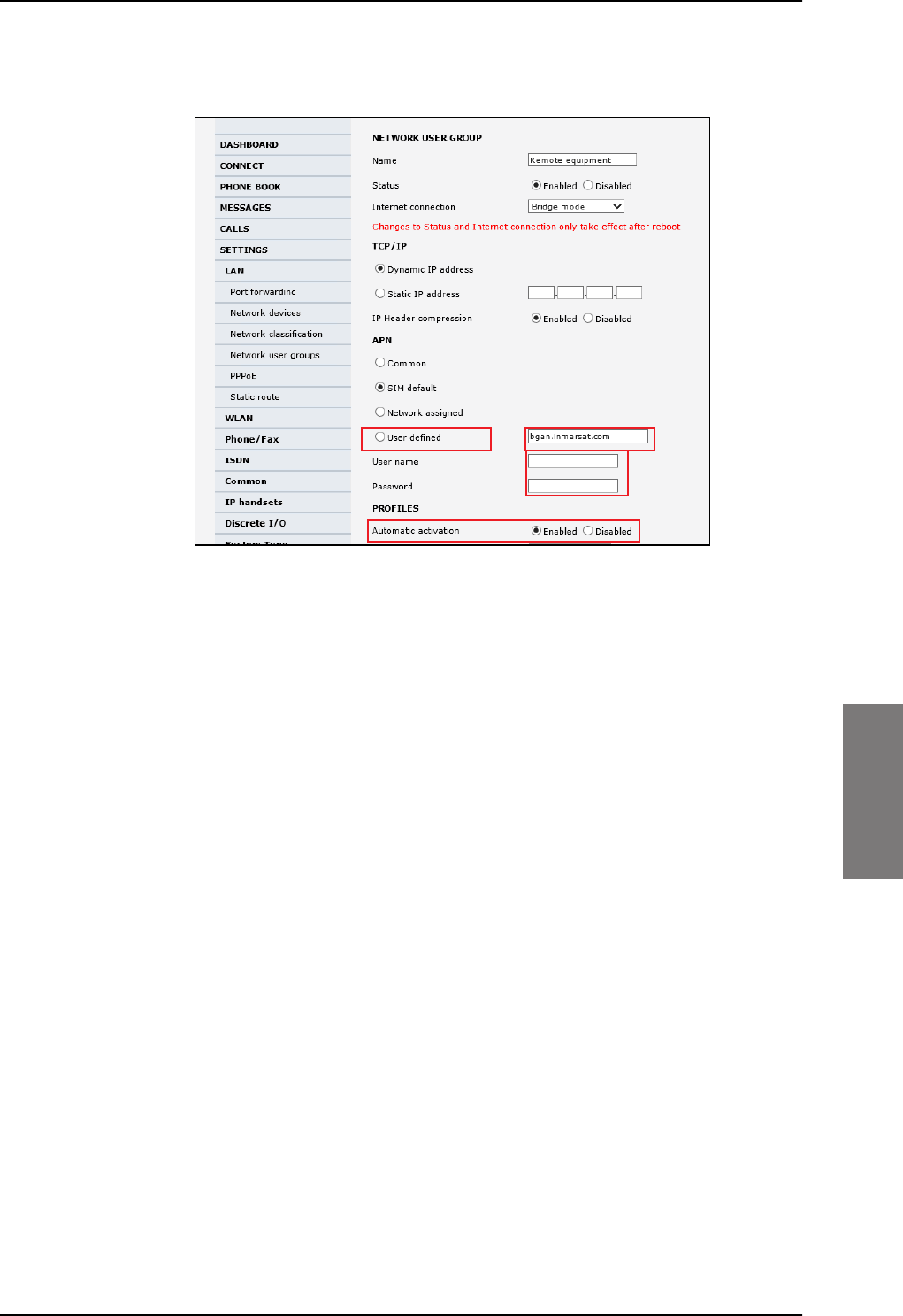
Configuration tasks
98-127093-H Chapter 6: Configuration of the AVIATOR 200/300/350 system 6-5
6666
6. Enter the APN from your service provider. For detailed instructions see Set up the
network user groups on page 6-59.
Figure 6-8: Basic configuration of the SBU, step 6/6
12
3
4
SB-Lite.book Page 5 Tuesday, September 5, 2017 1:38 PM

Tool for setup and use: Built-in web interface
6-6 Chapter 6: Configuration of the AVIATOR 200/300/350 system 98-127093-H
6.2 Tool for setup and use: Built-in web interface
Use the built-in web interface of the SBU to access the SBU configuration settings in the
CM. A subset of the configuration settings are stored in a write-protected area of the CM.
This subset contains the physical settings for the antenna, cabling and other external input.
To set up or change the settings of the write-protected area you must
connect a PC to the connector marked Maintenance on the SBU front plate.
You can view all settings from any LAN or WLAN interface.
The CM also contains the SIM card for accessing the SwiftBroadband service. The settings
that can only be changed when connected to the SBU maintenance connector are:
•Discrete I/O settings
• System type
• Cable loss data in Settings, RF settings,
• Input from navigational systems in Settings, External systems
• Enabling options (Router, WLAN) in Settings, Flex.
No installation of software is necessary because the web interface is built into the SBU.
Browsers supported
The web interface is built into the terminal and is used for operating, setting up and
configuring the system.
You can access the web interface from a computer with a standard Internet browser.
Important
Note For information on daily use of the AVIATOR 200/300/350 system refer to the
AVIATOR 200/300/350 User Manual.
SB-Lite.book Page 6 Tuesday, September 5, 2017 1:38 PM
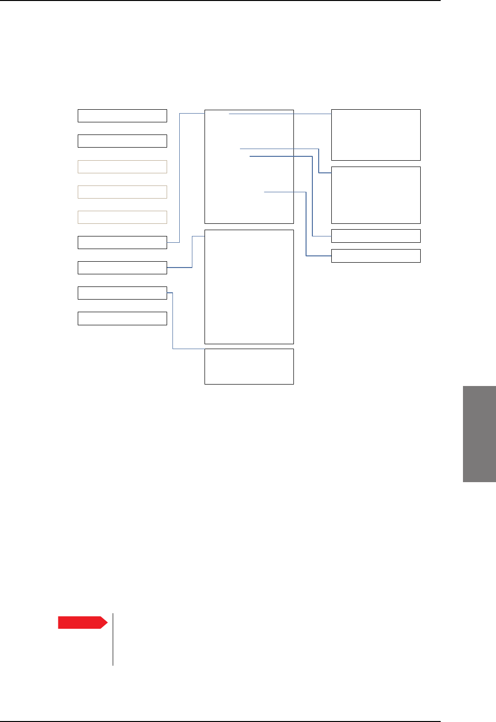
Tool for setup and use: Built-in web interface
98-127093-H Chapter 6: Configuration of the AVIATOR 200/300/350 system 6-7
6666
6.2.1 Topics in the web interface
The following drawing shows the topics available in the web interface. The topics in grey
are mainly used during daily use of the system, they are described in detail in the
AVIATOR 200/300/350 User Manual.
Figure 6-9: Topics in the web interface
6.2.2 Check the connection to the web interface
To check whether you can connect to the web interface of the SBU do as follows:
1. Power up the AVIATOR 200/300/350 system. Wait until the LEDs on the front plate
show that the system is ready to be configured.
• Power LED: Green, then wait for approximately one minute.
2. Connect a PC to the Maintenance interface (standard Ethernet) on the front plate of
the SBU.
If you want to change the setup of the user interfaces and change network usage you
can use any of the terminal LAN interfaces (up to 6) installed in the aircraft cabin or the
Wireless connection, if available. If you want to change the physical settings for the
antenna, cabling and other external input you must use the SBU maintenance
connector at the front of the SBU.
3RUWIRUZDUGLQJ
1HWZRUNGHYLFHV
1HWZRUNFODVVLILFDWLRQ
1HWZRUNXVHUJURXSV
333R(
6WDWLFURXWH
&DOOIRUZDUG
&DOOEDUULQJ
&DOOZDLWLQJ
/LQHLGHQWLILFDWLRQ
&ORVHGXVHUJURXS
/RFDOH[FKDQJH
/$1
:/$1
3KRQH)D[
,6'1
&RPPRQ
,3KDQGVHWV
'LVFUHWH,2
6\VWHPW\SH
5)VHWWLQJV
([WHUQDOV\VWHPV
)/(;
7UDFNLQJ
8SORDG
&DOOFKDUJHV
/RJKDQGOLQJ
'DWDOLPLWV
3URILOHV
7UDIILFIORZILOWHUV
6,03,1
6,0/RFN
8VHUSHUPLVVLRQV
5HPRWHPDQDJHPHQW
/LQNPRQLWRULQJ
5HPRWHDFWLYDWLRQ
5HVWULFWHGGLDOLQJ
0XOWLYRLFH
(YHQWOLVW
(YHQWORJ
([WHQGHGVWDWXV
6HOIWHVW
'$6+%2$5'
&211(&7
3+21(%22.
0(66$*(6
&$//6
6(77,1*6
$'0,1,675$7,21
+(/3'(6.
6,7(0$3
&DOOVHWWLQJV
&08$&$56
Important For systems without the built-in router option enabled, i.e. the basic version or
the version with Wireless option only: To use the SBU Maintenance
connector disconnect or switch off any PC connected to another LAN
interface of the SBU.
SB-Lite.book Page 7 Tuesday, September 5, 2017 1:38 PM
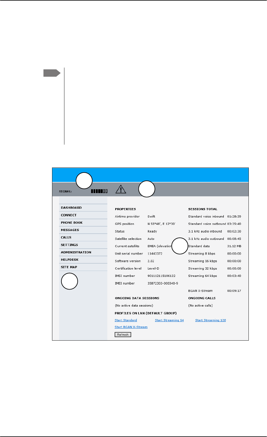
Tool for setup and use: Built-in web interface
6-8 Chapter 6: Configuration of the AVIATOR 200/300/350 system 98-127093-H
Access the web interface
To access the web interface, do as follows:
1. Open your browser and enter the IP address of the SBU. The standard IP address is
192.168.0.1.
If the local IP address of the SBU has been changed and you do not have the
new address, you can temporarily set the IP address to the default value by
pushing the Reset button on the front plate of the SBU. For detailed
instructions see How to reset the IP address or the terminal software to
default settings on page 7-15.
For further information on the Reset button, see IP Reset (Default) button on
page 7-14.
For further information on IP addresses of the SBU see Set up the LAN IP
addressing on page 6-19.
2. The web interface opens directly with the DASHBOARD page.
The web interface consists of the following sections:
1. The navigation pane holds the main menu. Clicking an item in the menu opens a
submenu in the navigation pane or a new page in the contents section.
2. The signal status field shows the signal strength. The signal strength can vary during
operation, depending on the current position relative to the Inmarsat satellite and the
call or data session activity.
Note
Figure 6-10: Sections of the web interface (example for AVIATOR 350)
1
23
4
SB-Lite.book Page 8 Tuesday, September 5, 2017 1:38 PM
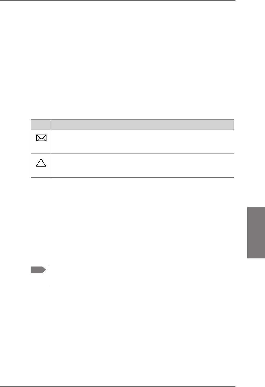
Tool for setup and use: Built-in web interface
98-127093-H Chapter 6: Configuration of the AVIATOR 200/300/350 system 6-9
6666
3. The icon bar shows icons for new SMS messages and for active events, when relevant.
For explanations of the icons, see the next section, Icons in the icon bar.
4. The contents section shows the page selected in the navigation pane. This section is
used for viewing or changing settings, or for performing actions.
When the Dashboard is displayed you have verified that the connection to the SBU can be
established. The web interface is ready for use. You can continue to configure the system.
If you cannot establish a connection to the SBU there might be problems with the Proxy
server settings of your PC. See Proxy server settings in your browser on page 6-9 for
further information.
Icons in the icon bar
The following icons may appear in the icon bar in the web interface:
Navigate the web interface
•To expand a menu, click the menu in the navigation pane.
•To access status and settings, click the relevant subject in the navigation pane or
click the relevant icon in the icon bar. The status or settings are displayed in the contents
section.
•To get an overview over the submenus available use the site map, click SITE
MAP in the navigation pane. Click on items in the site map to go directly to the relevant
location.
Proxy server settings in your browser
If you are connecting your computer using a LAN or WLAN interface, the Proxy server
settings in your browser must be disabled before accessing the web interface. Most
browsers support disabling of the Proxy server settings for one specific IP address, so you
can disable Proxy server settings for the web interface only, if you wish. Consult your
browser help for information.
To disable the use of a Proxy server completely, do as follows:
Icon Explanation
A new SMS message, or information of Voice mail, has arrived. Click the icon to
see new messages or information of Voice mail. For further information, see the
AVIATOR 200/300/350 User Manual.
An event is active. Click the icon to see a list of active events. For explanations
of the event messages, see the AVIATOR 200/300/350 User Manual. Note that
this icon will remain in the icon bar as long as the event is still active.
Table 6-1: Web interface: Icons
Note You can limit access to some parts of the web interface for certain users. Then the
parts are grayed out. For information on how to set up user permissions, see Set
up user permissions on page 6-87.
SB-Lite.book Page 9 Tuesday, September 5, 2017 1:38 PM
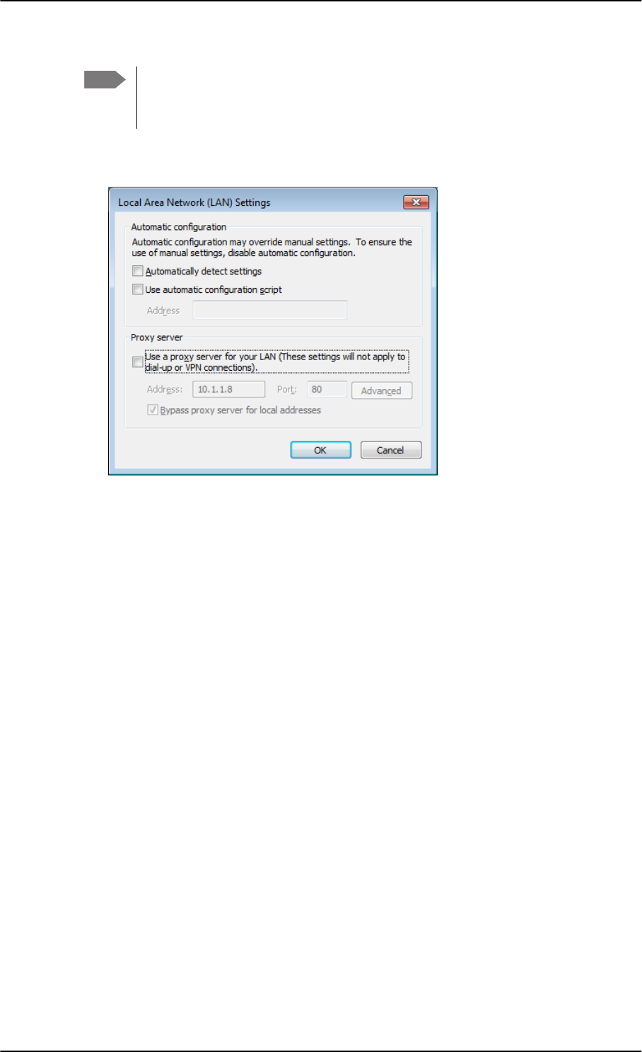
Tool for setup and use: Built-in web interface
6-10 Chapter 6: Configuration of the AVIATOR 200/300/350 system 98-127093-H
1. In Microsoft Internet Explorer, select Tools > Internet Options > Connections >
LAN Settings.
2. Clear the box labeled Use a proxy server for your LAN.
3. Click OK.
When the proxy server settings are disabled, close and restart your browser. You may need
to change this setting back on return to your Internet connection.
IP address and DNS server address setup
To check whether automatic IP address and DNS server address is obtained automatically
for your computer, do as follows (example for Windows 7):
1. Go to Control Panel > Network and Internet > Network and Sharing Center.
2. Click on the LAN connection you want to use.
3. Select Properties, highlight Internet Protocol Version 4 (TCP/IPv4).
4. Click Properties.
5. Make sure that the following is selected:
- Obtain an IP address automatically
- Obtain DNS server address automatically
Note The following description is for Microsoft Internet
Explorer. If you are using a different browser, the
procedure may be different.
SB-Lite.book Page 10 Tuesday, September 5, 2017 1:38 PM
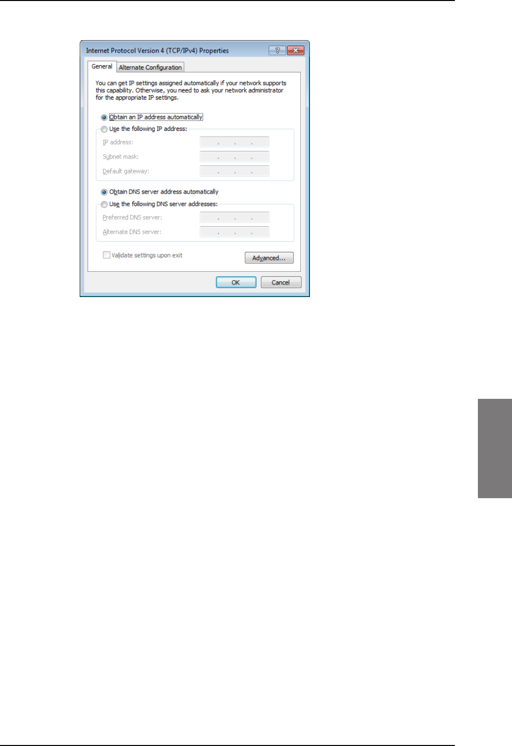
Tool for setup and use: Built-in web interface
98-127093-H Chapter 6: Configuration of the AVIATOR 200/300/350 system 6-11
6666
Allocating IP addresses and DNS server lookups are handled by the SBU.
SB-Lite.book Page 11 Tuesday, September 5, 2017 1:38 PM
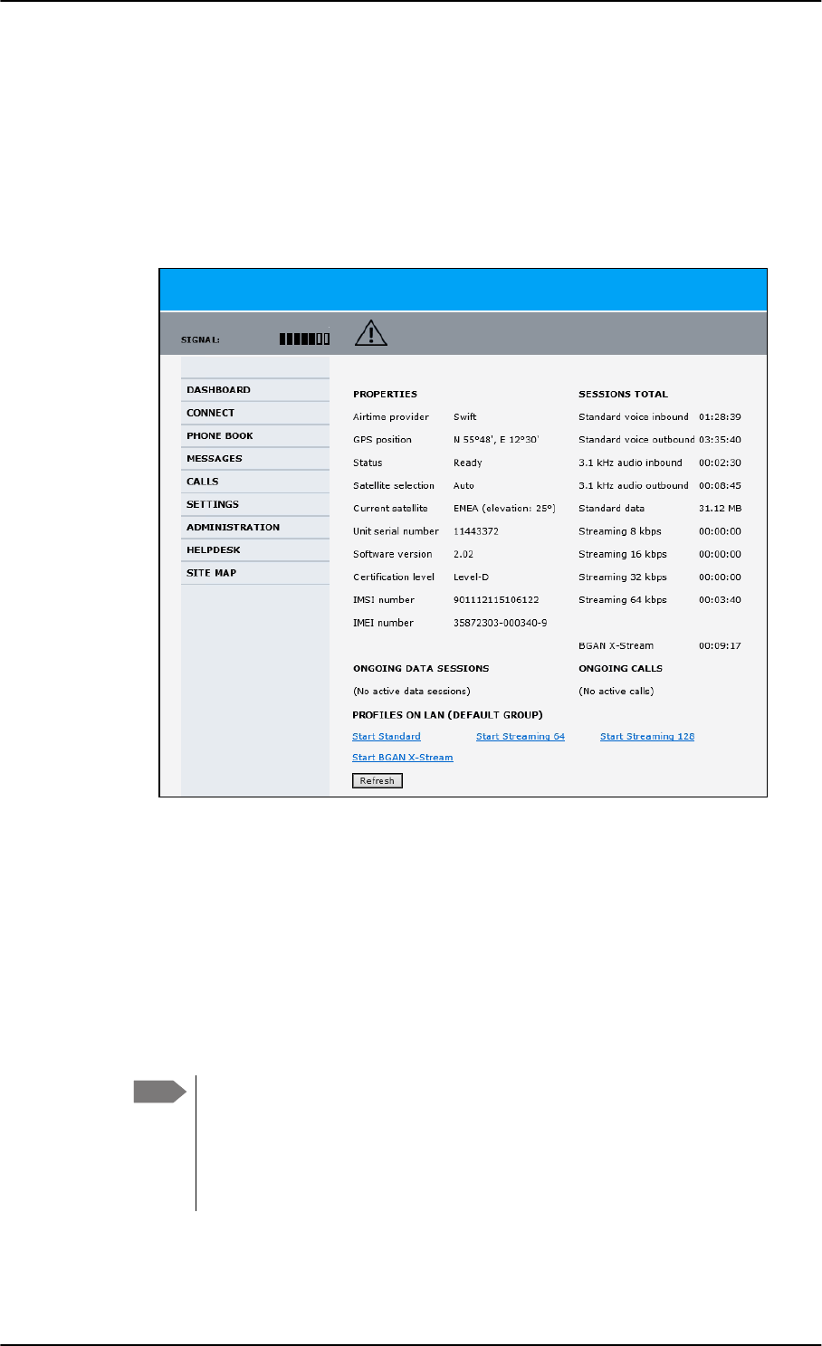
The Dashboard
6-12 Chapter 6: Configuration of the AVIATOR 200/300/350 system 98-127093-H
6.3 The Dashboard
6.3.1 Overview
The Dashboard is the first screen that is displayed when the user or administrator enters the
IP address of the web interface. The Dashboard is used for control and inspection of
ongoing communication and for viewing properties and status of the SBU and antenna.
Figure 6-11: Web interface: Dashboard (Example: AVIATOR 350) a
a. For I3 coverage the Status field shows: Logged off. When I4 coverage is available again, the
system logs automatically on.
6.3.2 Properties
The PROPERTIES section of the DASHBOARD shows the following information:
•Airtime provider. The name of your Airtime Provider.
•GPS position. The GPS position of your AVIATOR 200/300/350 system.
•Status. The status of the SBU and antenna.
Examples of status information are: Scanning, Ready and Data active.
Note In some cases, the BGAN network does not allow the position to be displayed to
the user. If this is the case, the display may just show GPS acquired. This
means that the GPS position is received, but the user is not allowed to see it.
This also applies if the AVIATOR 200/300/350 is not yet registered on the
BGAN network, but the GPS position is received.
SB-Lite.book Page 12 Tuesday, September 5, 2017 1:38 PM

The Dashboard
98-127093-H Chapter 6: Configuration of the AVIATOR 200/300/350 system 6-13
6666
•Satellite selection. The satellite selected for logon. For further information, see To
select the preferred BGAN satellite on page 6-18.
•Current satellite. The currently used satellite and elevation angle.
•Unit serial number. The serial number of the SBU.
•Software version. The version of the software embedded in the SBU.
•Certification level. This field shows whether the system is Level-D or Level-E certified.
If Inconsistent is displayed, it means there is a mismatch with Level-D
and Level-E certified units or software. This is not allowed.
•IMSI number. The IMSI number (International Mobile Subscriber Identity) of the SBU.
This is a unique number that identifies the SIM card of your SBU.
•IMEI number. The IMEI number (International Mobile Equipment Identity) of the
SBU. This is a unique number that identifies your SBU.
6.3.3 View information on calls and data sessions
The following sections in the Dashboard show information on calls and data sessions.
•ONGOING DATA SESSIONS is a list of data profiles that are currently active, including
the external IP address that is assigned to each profile.
•ONGOING CALLS is a list of calls that are currently active. The list shows the call type
and the time connected for each call.
•SESSIONS TOTAL lists the totals for each session type. The list shows the session type
with accumulated time for voice and Streaming data, and MB transferred for Standard
data.
The counters show totals for sessions since the counters were last cleared. For information
on how to clear the counters, see Log handling on page 6-78.
Important
SB-Lite.book Page 13 Tuesday, September 5, 2017 1:38 PM
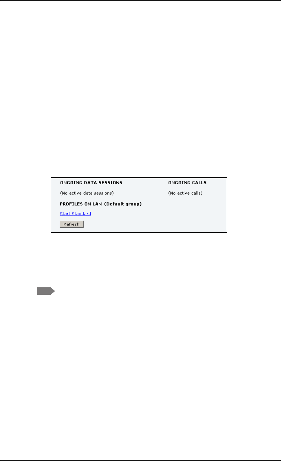
The Dashboard
6-14 Chapter 6: Configuration of the AVIATOR 200/300/350 system 98-127093-H
6.3.4 Profiles on the dashboard
There is also a section on the dashboard showing the network user group and the profile(s)
available for the current user. Here you can start the connections allowed for the current
network user group. For more information on network user groups and profiles see
LAN/WLAN network users on page 6-57.
Start or stop a standard data connection
On the Dashboard you can see under PROFILES ON LAN whether a standard connection is
active or not.
To start or stop a Standard connection for your Network user group do as follows:
1. Open your Internet browser and enter the IP address of the AVIATOR 200/300/350
SBU (default: http://192.168.0.1) to access the Dashboard of the web interface.
2. Locate PROFILES ON LAN at the bottom of the page.
3. Click Start <name of profile>, in this case: Start Standard, or Stop <name of
profile> to stop the connection.
Figure 6-12: Web interface: Start a data connection
4. Click Refresh to update the current state of the connection(s). Note that there might
be some latency when updating the connection status, you might have to wait and click
Refresh again to update the Dashboard to the current state.
Note The PDP context for a data session is not activated before any unit in the LAN tries
to communicate, e.g. sends a DHCP request. You can also remotely start a data
connection, see Remote activation of a connection using SMS on page 6-90.
SB-Lite.book Page 14 Tuesday, September 5, 2017 1:38 PM
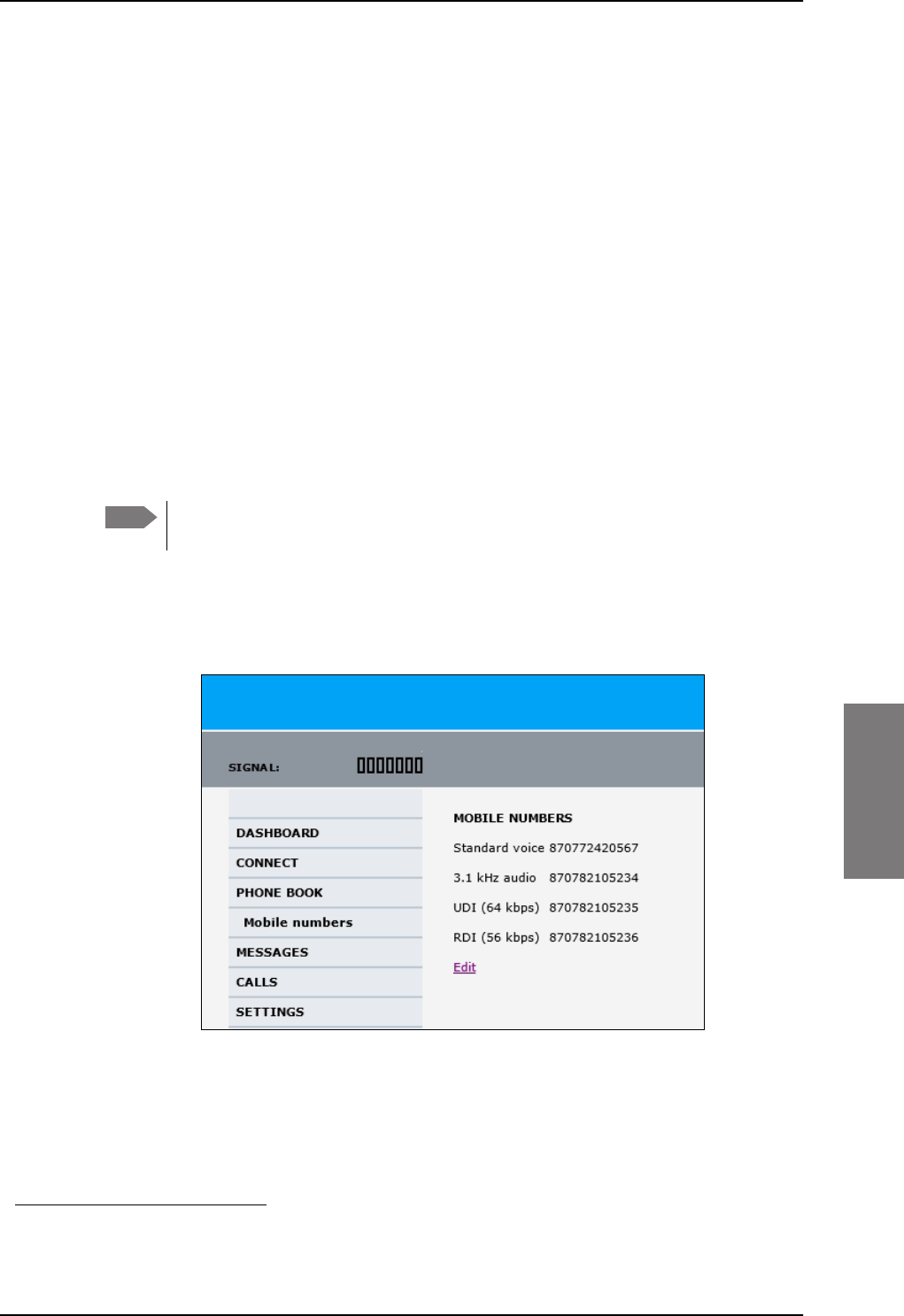
The phone book
98-127093-H Chapter 6: Configuration of the AVIATOR 200/300/350 system 6-15
6666
6.4 The phone book
6.4.1 General usage
The phone book is stored in the Configuration module. In the phone book you can:
• Add new names and phone numbers.
• Modify or delete existing names and phone numbers.
• Look up phone numbers.
• Look up short-dial numbers for easy dialing from a handset.
For information how to access the phone book and how to add, edit and delete phone book
entries see the AVIATOR 200/300/350 User Manual.
6.4.2 View and edit the mobile and additional numbers1
The mobile numbers are the phone numbers to use when making a call to the terminal.
These numbers are not listed at delivery. Enter the numbers received from the
Service and Airtime Provider.
To view the mobile numbers
To view the mobile numbers of the SBU, select PHONE BOOK > Mobile numbers from
the left navigation pane.
Figure 6-13: Web interface: Phone book, mobile numbers (example, no Multi-voice)
1. Available for systems with Multi-voice and subscriptions with additional numbers.
Note
SB-Lite.book Page 15 Tuesday, September 5, 2017 1:38 PM
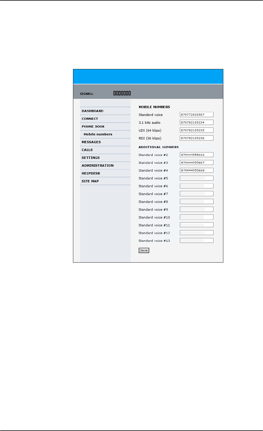
The phone book
6-16 Chapter 6: Configuration of the AVIATOR 200/300/350 system 98-127093-H
To enter or edit the mobile numbers
To enter or edit the mobile numbers, click Edit at the bottom of the page, type in the
numbers received from your Airtime Provider and click OK. If Multi-voice is part of your
system, the additional numbers from your airtime provider can be entered in the web
interface.
Figure 6-14: Web interface: Phone book, mobile numbers (example, with Multi-voice)
SB-Lite.book Page 16 Tuesday, September 5, 2017 1:38 PM

To set up the interfaces
98-127093-H Chapter 6: Configuration of the AVIATOR 200/300/350 system 6-17
6666
6.5 To set up the interfaces
The following subsections are available:
•The SETTINGS page
•Select the preferred BGAN satellite
•Configure the LAN interface
•WLAN interface (option)
•Configure the Phone/Fax interface (2-Wire)
•Configure the ISDN interface
•Set the common interface settings
•Set up call services
•Manage AVIATOR Wireless Handsets
•Configure the discrete I/O interfaces
•Set the system type
•Configure RF settings
•Set up the navigational input
•Calibrate the NRS magnetometer in the TT-5006A IGA
•Set up CMU/ACARS (option)
•Enable system options with FLEX keys
•Tracking
•SB-Safety Voice (option)
6.5.1 The SETTINGS page
From the SETTINGS page you have access to the submenus for system settings and
configuration.
•LAN to configure the settings of the local area network.
•WLAN to configure the wireless network adapter.
•Phone/Fax to configure the phone and fax interfaces.
•ISDN to configure the ISDN interface.
•Common to configure settings that are common for all interfaces.
•IP handsets to configure connected AVIATOR Wireless Handsets.
•Discrete I/O to configure the discrete inputs/outputs of the installation.
•System type to select the AVIATOR 200/300/350 system
•RF settings to configure the cable losses of the installation.
•External systems to select antenna type, configure the external navigational system
and set up the ACARS/CMU connection.
SB-Lite.book Page 17 Tuesday, September 5, 2017 1:38 PM
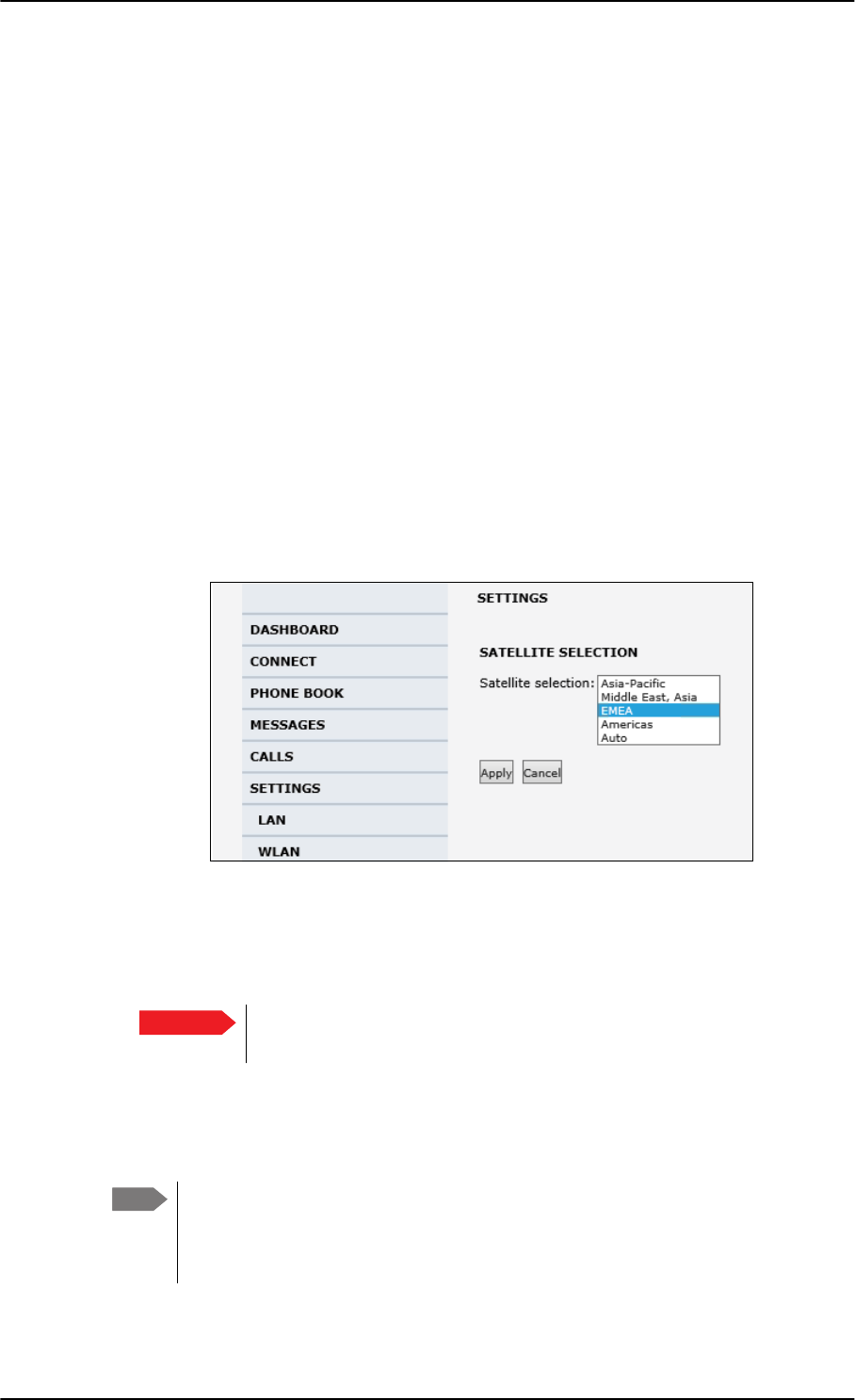
To set up the interfaces
6-18 Chapter 6: Configuration of the AVIATOR 200/300/350 system 98-127093-H
•FLEX for the viewing and enabling options and AVIATOR systems.
•Tracking to send position information to a server
•Upload to upload new application software to the SBU.
A text message on the screen informs you if you need to reboot the system to activate a
new setting or configuration.
To access this page, select SETTINGS from the left navigation pane.
6.5.2 Select the preferred BGAN satellite
By default the SBU is set up to automatically find the most appropriate satellite to connect
to (Auto mode). However, if you are located in an area with more than one BGAN satellite
available, you can select the satellite you prefer to use when registering on the BGAN
network.
To select the preferred BGAN satellite
To select the preferred BGAN satellite, do as follows:
1. Select SETTINGS from the left navigation pane.
Figure 6-15: Web interface: Settings, satellite selection
2. Select the satellite you prefer to use.
If you select Auto (default setting) the AVIATOR 200/300/350 system automatically
uses the most appropriate satellite.
3. Click Apply.
The AVIATOR 200/300/350 terminates all ongoing connections and de-registers from
the current satellite before registering on the new satellite.
Important If you have any ongoing calls or data sessions, they will be terminated
when you click Apply to change the satellite.
Note If you have selected a specific satellite, the AVIATOR 200/300/350 system will
only try to establish a connection to the selected satellite. This means that if the
antenna is outside the coverage area for that satellite, the AVIATOR 200/300/350
system will not be able to register with the BGAN network.
SB-Lite.book Page 18 Tuesday, September 5, 2017 1:38 PM
To set up the interfaces
98-127093-H Chapter 6: Configuration of the AVIATOR 200/300/350 system 6-19
6666
6.5.3 Configure the LAN interface
Overview
The SBU has 6 LAN connectors plus 1 LAN maintenance connector on the SBU front plate.
The major part of the LAN parameters are set up in the network management pages, which
require an administrator password. For information on these settings, refer to LAN/WLAN
network users on page 6-57.
This page is by default not protected by an admin password. You can limit
access to this page for certain user groups, for further details see Set up user
permissions on page 6-87.
Set up the LAN IP addressing
In the web interface you can set up the IP addressing between the SBU and devices
connected to the SBU. The SBU has a built-in DHCP server which can be used to
dynamically assign IP addresses to devices connected to the SBU.
You can also set up the local IP address used by the connected devices to access the SBU.
The Local IP address is the IP address of the SBU. It is used for accessing the web interface.
The IP address towards the BGAN network is assigned by Inmarsat and visible on the
Dashboard when the connection is active.
Figure 6-16: SBU IP addresses: Local and global IP addresses, default
CAUTION! All connections to the LAN interface may be affected when
you change the settings below. This also includes your own current
connection.
Note No router option: If the SBU does not have the router option and works in
single-user mode, only one device can be connected to it. This device cannot have
a static IP address, it must use the DHCP server of the SBU.
6%8
'HYLFH
'HYLFH
DVVLJQHGE\WKH
WHUPLQDO'+&3
DVVLJQHGE\WKH
WHUPLQDO'+&3
/RFDO,3
DGGUHVVRI
6%8
*OREDO,3
DGGUHVVRI
6%8
$VVLJQHG
E\%*$1
QHWZRUN
SB-Lite.book Page 19 Tuesday, September 5, 2017 1:38 PM
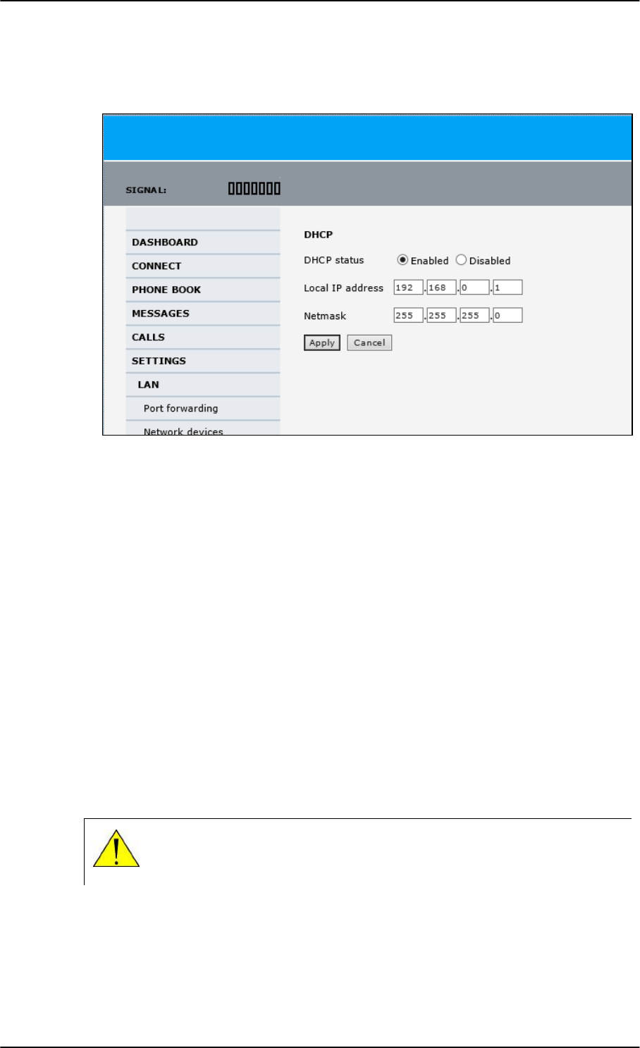
To set up the interfaces
6-20 Chapter 6: Configuration of the AVIATOR 200/300/350 system 98-127093-H
To change the local IP address of the SBU do as follows:
1. From the left navigation pane, select SETTINGS > LAN.
Figure 6-17: Web interface: Settings, LAN
2. At DHCP status, select Enabled (recommended), or Disabled.
•Enabled: The SBU assigns dynamic IP addresses to devices connected to the SBU.
•Disabled: You need to set up a static IP address in the connected device.
3. To change the Local IP address and the Netmask, type in the new address and
netmask. By default, the address is 192.168.0.1 and the netmask is 255.255.255.0.
4. Click Apply.
Port forwarding
Port forwarding enables you to set up a server connected to the SBU while the terminal is in
Router mode. Without port forwarding it would not be possible to contact the server from
the Internet. If you want to use port forwarding, the global IP address of the SBU should be
a static IP address. Check with your service provider for availability of a static global IP
address. Note that if not agreed otherwise, the global IP address of the SBU will be
dynamically assigned as the SBU signs on to the BGAN network.
For information on how to set the terminal in Router mode, see Set up the network user
groups on page 6-59.
The following example shows how to allow internet access to a mail server (smtp)
connected to the terminal.
CAUTION! This page is by default not protected by an admin password.
You can limit access to this page for certain user groups, for further details
see Set up user permissions on page 6-87.
SB-Lite.book Page 20 Tuesday, September 5, 2017 1:38 PM
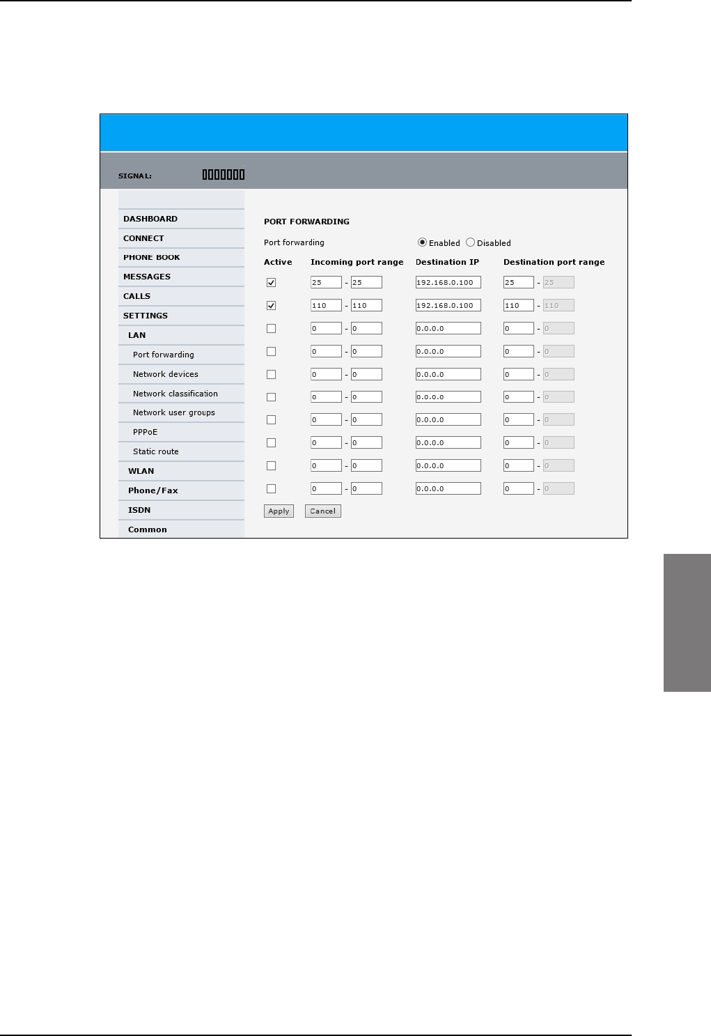
To set up the interfaces
98-127093-H Chapter 6: Configuration of the AVIATOR 200/300/350 system 6-21
6666
The mail server in this example has the IP address 192.168.0.100.
1. Select SETTINGS > LAN > Port forwarding in the left navigation pane.
Figure 6-18: Web interface: Settings, LAN, Port forwarding
2. Select Enabled to generally enable port forwarding.
3. Type in the Incoming port range.
4. Type in the Destination IP address, which in this example is the IP address of the mail
server: 192.168.0.100.
5. Type in the Destination port range.
6. Repeat step 3 to step 5 to set up port forwarding to additional servers.
7. In the Active column, select which ports should have port forwarding activated.
8. Click Apply.
You can now access the mail server from the Internet, using the external IP address of the
SBU. For more information on setting an external IP address see step 6 in Edit a network
user group on page 6-59.
SB-Lite.book Page 21 Tuesday, September 5, 2017 1:38 PM
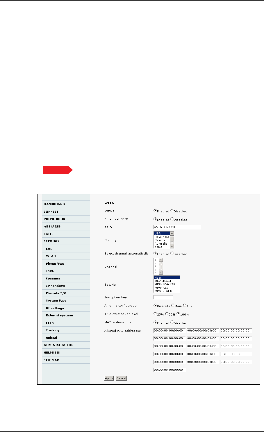
To set up the interfaces
6-22 Chapter 6: Configuration of the AVIATOR 200/300/350 system 98-127093-H
6.5.4 WLAN interface (option)
Note that the settings from the LAN window, except Enabled/Disabled, also apply for the
WLAN interface. See Configure the LAN interface on page 6-19.
Enable the WLAN interface
To enable the WLAN interface, do as follows:
1. Make sure that the discrete input, i.e. TP5 WLAN Enable input, is wired correctly for
WLAN enable. Read more about this in Pins for non-configurable discrete inputs on the
SBU on page 5-43 and WLAN pins on page 5-34.
2. In the web interface on the page SETTINGS > WLAN select the status Enabled.
For systems without the built-in Wireless option (WLAN) the submenu will still be available
in the web interface and the screen will show that the WLAN option is not enabled. To
enable the WLAN option enter the FLEX key for this option in the submenu Settings >
FLEX. The WLAN interface functions properly if both of the above conditions are
fulfilled.
For software 4.00 and higher and SB-Safety Voice: Do not enable WLAN.
To configure the WLAN interface, do as follows:
1. Select SETTINGS > WLAN.
Figure 6-19: Web interface: Settings, WLAN (Example: AVIATOR 350)
2. You can enable or disable the WLAN (default setting: Enabled).
Important
SB-Lite.book Page 22 Tuesday, September 5, 2017 1:38 PM

To set up the interfaces
98-127093-H Chapter 6: Configuration of the AVIATOR 200/300/350 system 6-23
6666
3. For Broadcast SSID, select Enabled (default) or Disabled.
Enabled: your WLAN access point is shown to other users.
Disabled: your WLAN access point is hidden.
4. Type in the SSID of your choice or accept the default SSID, which is the name of the
installed system: AVIATOR 200, AVIATOR 300 or AVIATOR 350.
The SSID (Service Set IDentifier) is the name of the wireless local area network. It is
text with maximum 32 characters.
All wireless devices on a WLAN must use the same wireless local area network in order
to communicate with each other.
5. Select the Country for your present location. The default setting is USA. For a list of
countries that can use WLAN with the setting USA see Countries where the “US”
country code applies on page D-2.
6. If you want to let the system automatically find a channel set Select channel
automatically to Enabled. Then the Channel list will be grayed out.
If you have set Select channel automatically to Disabled you can set the Channel
used for communication on the WLAN interface.
7. Select the Security standard. Select one of the following encryption standards:
• None (default)
• WEP-40/64, enter the encryption key in hexadecimal format.
• WEP-104/128, enter the encryption key in hexadecimal format.
• WPA-TKIP, enter the encryption key in text format.
• WPA2-AES, enter the encryption key in text format.
8. Type in the Encryption key for the selected Security standard. This is not applicable if
you have selected Security mode None.
9. In Antenna configuration you set whether you have two or one WLAN antennas,
and how a single WLAN antenna is connected to the SBU:
•Diversity: 2 WLAN antennas are connected
•Main: A single WLAN antenna is connected to SBU TP A4
•Aux: A single WLAN antenna is connected to SBU TP A2
10. TX output power level: You can control the maximum transmitted output power
from the SBU rear receptacle TP
A2 or TP A4:
• 100% – 20 dBm, 100 mW
• 50% – 17 dBm, 50 mW
• 25% – 14 dBm, 25 mW
11. Select Enabled or Disabled next to MAC address filters.
Enabled: You can set up a list of MAC addresses that are allowed access to your WLAN.
Any device whose MAC address is not on the list will be denied access.
Disabled: There will be no restrictions on MAC addresses.
12. If you have enabled MAC address filters, type in the Allowed MAC addresses.
The list may contain up to 16 MAC addresses.
13. Click Apply.
SB-Lite.book Page 23 Tuesday, September 5, 2017 1:38 PM
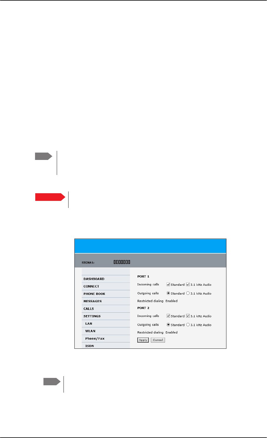
To set up the interfaces
6-24 Chapter 6: Configuration of the AVIATOR 200/300/350 system 98-127093-H
To disable the WLAN interface
To disable the built-in WLAN interface, do as follows:
• Disable the WLAN interface using the TP5 WLAN Enable discrete input. Read more
about this in Pins for non-configurable discrete inputs on the SBU on page 5-43 and
WLAN pins on page 5-34.
or
• In the web interface go to Settings > WLAN and select Disable.
If the WLAN option is not enabled the page Settings > WLAN will still be available and the
screen will show information that the WLAN option is not enabled.
6.5.5 Configure the Phone/Fax interface (2-Wire)
To configure this interface do as follows:
1. Select SETTINGS > Phone/Fax from the left navigation pane.
Figure 6-20: Web interface: Settings, Phone/Fax
2. For each Phone/Fax port, set the call type for incoming and outgoing calls.
To identify Port 1 and Port 2 see the drawings of your specific installation.
Mark the connectors in the air cabin accordingly.
The call types are described in more detail in the AVIATOR 200/300/350 User Manual
in the chapter Using a phone of fax machine.
Note By default all handsets connected to the system will ring on incoming calls. If you
have connected a fax, set the incoming call type on that 2-wire interface to
3.1 kHz Audio to avoid that the fax rings and answers an incoming Standard call.
Important With software 4.00 or higher and SB-Safety voice enabled, the 2-wire POTS
interface #2 is forced disabled.
Note
SB-Lite.book Page 24 Tuesday, September 5, 2017 1:38 PM
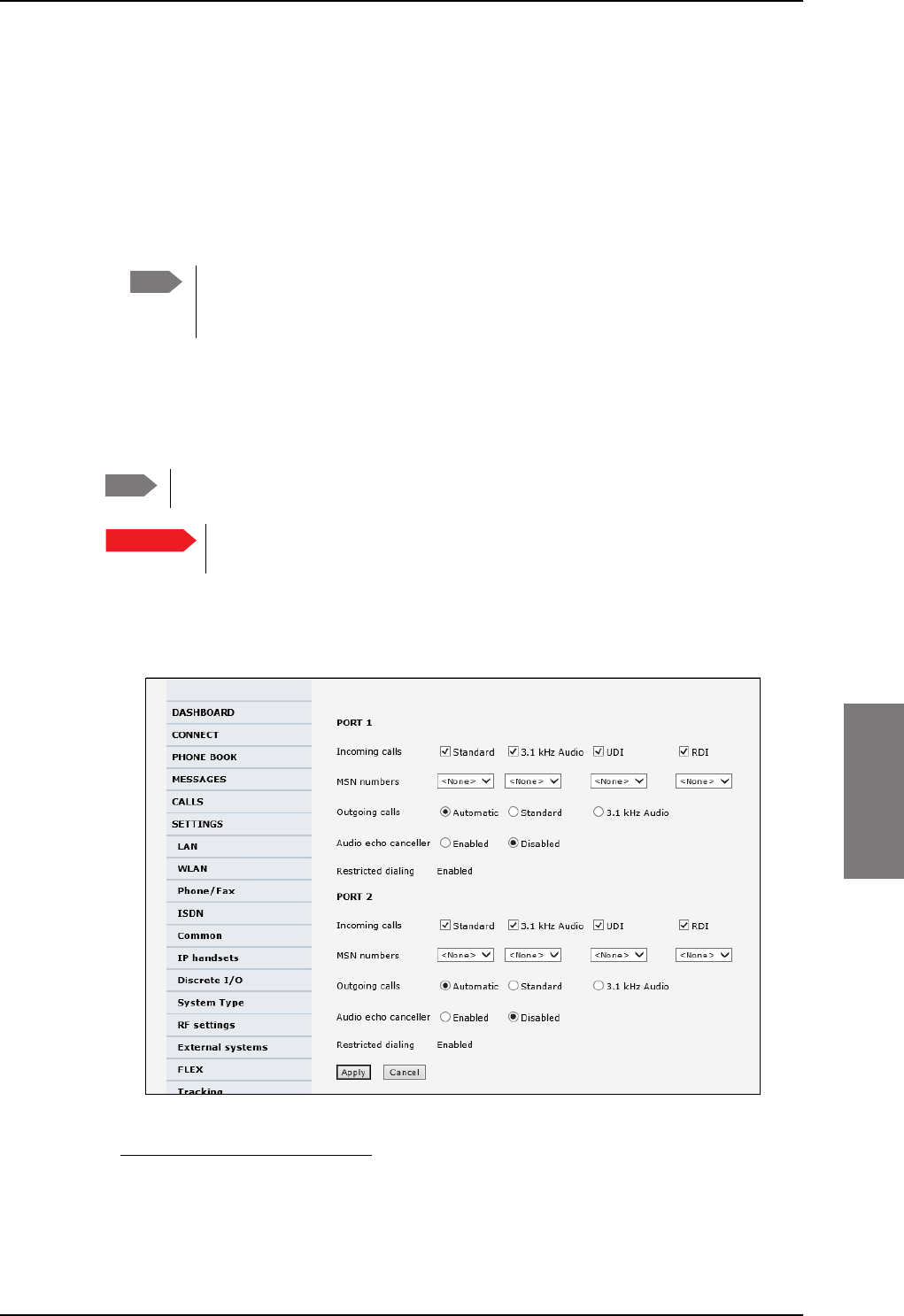
To set up the interfaces
98-127093-H Chapter 6: Configuration of the AVIATOR 200/300/350 system 6-25
6666
• For Incoming calls, you can check Standard or 3.1 kHz Audio or both.
If you check both, any device connected to the Phone/Fax interface will react (ring)
on incoming calls. 1
If you select only Standard, the Phone/Fax interface will only react on calls made to
the Standard phone number, and not on calls to the 3.1 kHz Audio number.
• For Outgoing calls, you can select either Standard or 3.1 kHz Audio. The selected
type will be used by default, if possible, for any outgoing call. Note, however, that fax
machines and modems must use 3.1 kHz Audio.
3. Click Apply.
6.5.6 Configure the ISDN interface
To configure the ISDN interface, do as follows:
1. Select SETTINGS > ISDN.
Figure 6-21: Web interface: Settings, ISDN
1.If Multi-voice is enabled and you have entered additional numbers in the phone book,
you can assign an additional number to this interface. For more information see Multi-
voice (option) on page 6-91.
Note You can override the default setting for outgoing calls by dialing 1* (force the
call to Standard) or 2* (force the call to 3.1 kHz Audio) before the number. For
further information, see the AVIATOR 200/300/350 User Manual.
Note The AVIATOR 200 does not support ISDN services.
Important With software 4.00 or higher and SB-Safety voice enabled ISDN is forced
disabled.
SB-Lite.book Page 25 Tuesday, September 5, 2017 1:38 PM

To set up the interfaces
6-26 Chapter 6: Configuration of the AVIATOR 200/300/350 system 98-127093-H
2. Set the call type(s) for incoming calls.
You can select Standard, 3.1 kHz Audio, UDI and/or RDI.1
3. Set the MSN (Multiple Subscriber Numbering) numbers that are to be assigned to each
call type. In most pieces of ISDN equipment you can program multiple subscriber
numbers. The number programmed into the equipment should be the dial-in number
that you wish that piece of equipment to answer.
If you set an MSN number to anything other than <None>, connected
devices must be programmed with these MSN numbers.
Note that this setting only applies to the call type selected above the MSN number, and
only if the connected device supports the call type used.
You have the following options with the MSN numbers:
•<None>. No MSN numbers are used. An incoming call is accepted in all devices
connected to this port.
•1*, 2*, 3* or 4*: If, for example, you select 1* at Standard call type, an incoming
Standard call is accepted by all devices that are programmed with the number 1* and
connected to the ISDN interface.
•0401, 0402: These are local numbers for separate devices connected to the ISDN
interface.
An incoming call is accepted by devices that are programmed with the selected
number and connected to the ISDN interface.
You can combine the MSN settings.
Example: You have two devices connected to the ISDN interface. One is
programmed with the numbers 1* and 0401, the other is programmed
with 1* and 0402.
In the web interface, you select the MSN number 1* under Standard.
If an incoming Standard call arrives, both devices will accept the call.
If you make a local call to one of the local numbers 0401 or 0402, only the
called device will accept the call.
4. Set the call type for outgoing calls.
• If you select Automatic, the call type will be determined by the calling device.
• If you select Standard, all outgoing calls, except UDI/RDI, will use the call type
Standard. If you make a 3.1 kHz Audio call it will be converted to a Standard call.
Outgoing UDI or RDI sessions will be not be influenced by this setting.
• If you select 3.1 kHz Audio, all outgoing calls, except UDI/RDI, will use the call type
3.1 kHz Audio. If you make a Standard call it will be converted to a 3.1 kHz Audio call.
Outgoing UDI or RDI sessions will be not be influenced by this setting.
1.If Multi-voice is enabled and you have entered additional numbers in the phone book,
you can assign an additional number to this interface. For more information see Multi-
voice (option) on page 6-91.
Note Connected devices will only receive incoming calls with the call types that are
selected here. For example, if only Standard is selected, and a G4 fax call (using
call type UDI) arrives, a fax connected to the ISDN port will not receive the
incoming call.
Important
SB-Lite.book Page 26 Tuesday, September 5, 2017 1:38 PM
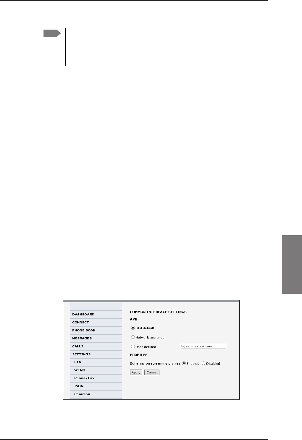
To set up the interfaces
98-127093-H Chapter 6: Configuration of the AVIATOR 200/300/350 system 6-27
6666
5. If you hear an echo in your handset and the handset does not have its own echo
canceller, enable the Audio echo canceller.
6. Click Apply.
6.5.7 Set the common interface settings
The settings under COMMON are common for all interfaces. Note, however, that in order to
use the common Access Point Name for an interface, you must select Common for the
APN setting when setting up the network user group.
Definition of Access Point Name (APN)
The APN is used by the network user to establish a connection to the required external
network. This means that the SBU must know the APN in order to be able to connect to the
external network. APNs are provided from the Airtime Provider. They may also be defined
on the SIM card.
The common APN
The common APN setting is defined here and can be selected for each network user group.
If you are using the same APN for many network user groups, it is easier to define it once,
and then simply select it for the relevant network user groups. Also, if you change the
common APN at a later stage, it is automatically updated for all network user groups where
the Common setting is selected.
To set up the common interface settings
To set up the Common interface settings do as follows:
1. Select SETTINGS > Common.
Figure 6-22: Web interface: Settings, Common
Note You can override the call type setting for outgoing calls by dialing one of the
following prefixes before the number:
• 1* (force the call to Standard)
• 2* (force the call to 3.1 kHz Audio)
SB-Lite.book Page 27 Tuesday, September 5, 2017 1:38 PM

To set up the interfaces
6-28 Chapter 6: Configuration of the AVIATOR 200/300/350 system 98-127093-H
2. Select the APN. You have the following options:
•SIM default. The APN is taken from the SIM card. This is the recommended option,
unless you have special requirements, i.e. your service provider does not
automatically provision for PS services.
•Network assigned. The APN is assigned from the network.
•User defined. Type in the APN. APNs are provided from the service provider.
3. At Buffering on Streaming profiles, select Enabled or Disabled.
• If you select Enabled, your Streaming connection will be buffered. This means that
the transmission is slightly delayed in order to ensure a precise and continuous data
stream.
• If you select Disabled, the Streaming connection will not be buffered. This means
the data is delivered immediately, but may vary slightly in transmission speed.
4. Click Apply.
How to use the common APN
When you configure the APN for your individual network user group, select Common to
use the setting from this page.
Where Common is selected in the individual network user groups, the setting will
automatically be updated when the Common APN is changed.
6.5.8 Set up call services
The setup of call services is also common for all interfaces.
The SBU must be registered on the BGAN network before
you can set up the call services in the web interface.
In the web interface you can set up the following supplementary services:
•Call forwarding
•Call barring
•Call waiting
•Line identification
•Closed user group
•Local exchange
Note that, depending on the network, some of these call service settings may prevent
others from being activated.
The settings apply for all connected devices using a circuit-switched service.
Note Use User defined if your service provider does not automatically provision your
SIM card. Contact your service provider for an APN or check the
documentation received from the service provider for an APN.
Note
SB-Lite.book Page 28 Tuesday, September 5, 2017 1:38 PM
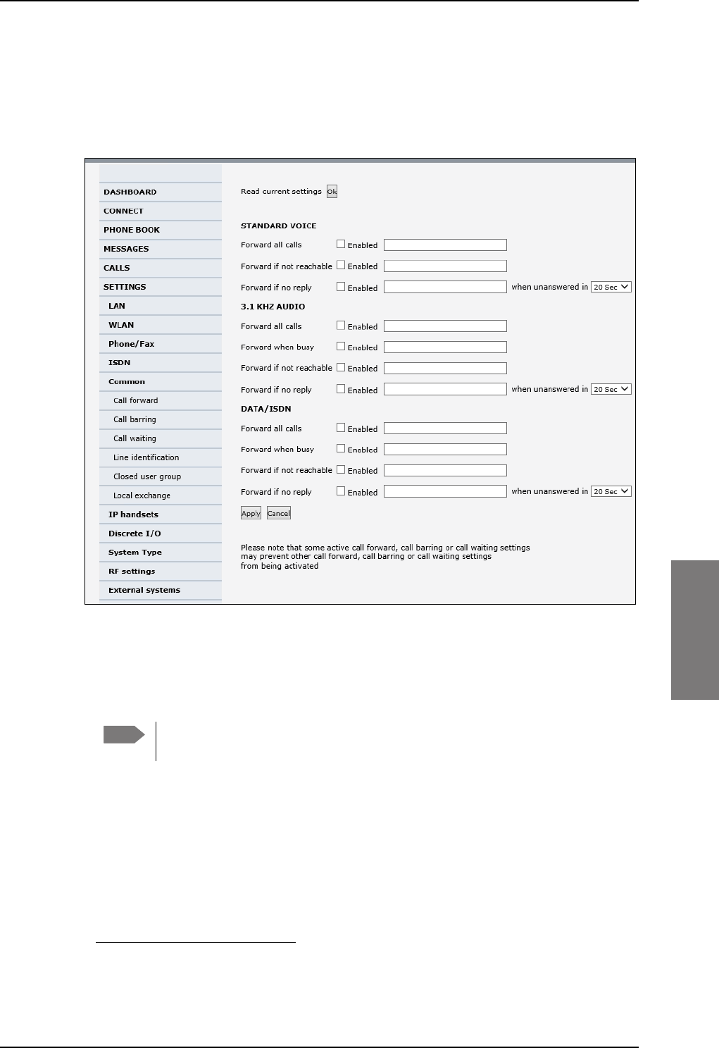
To set up the interfaces
98-127093-H Chapter 6: Configuration of the AVIATOR 200/300/350 system 6-29
6666
Call forwarding
You can set up the SBU to automatically forward incoming calls to another phone number.
To forward incoming calls do as follows:
1. Select SETTINGS > Common > Call forward from the left navigation pane.
Figure 6-23: Web interface: Settings, Common, Call forward
2. Click OK next to Read current settings to display the phone numbers for call
forwarding for the subscription. These numbers are operator controlled and come with
your airtime subscription (default). A message saying Operation in progress, please
wait. is displayed.
Allow sufficient time for the system to read the current settings over the
satellite connection.
3. For each call type, select Enabled next to the situation(s) in which you want to forward
incoming calls.1
4. Next to the enabled items, you can type in a phone number to forward the call to.
5. If you have selected Forward if no reply, select from the drop-down list the period of
time the system should wait before forwarding the call.
6. Click Apply.
Note
1. When Multi-voice is enabled, the “Forward when busy” setting is not available for Standard
voice.
SB-Lite.book Page 29 Tuesday, September 5, 2017 1:38 PM
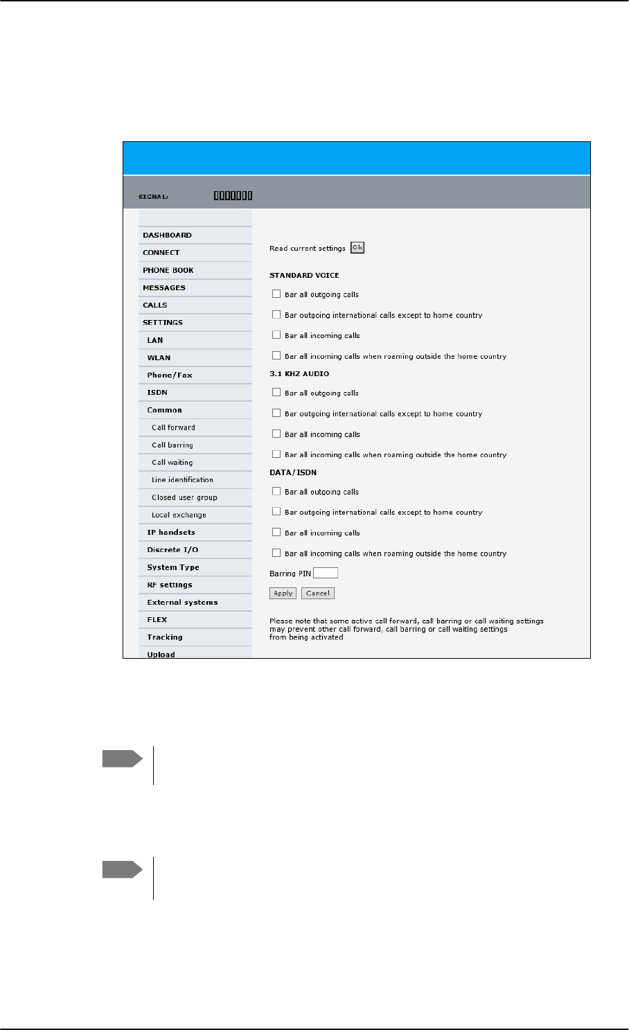
To set up the interfaces
6-30 Chapter 6: Configuration of the AVIATOR 200/300/350 system 98-127093-H
Call barring
Do as follows to bar incoming and/or outgoing calls to and from the SBU:
1. Select SETTINGS > Common > Call barring from the left navigation pane.
Figure 6-24: Web interface: Settings, Common, Call barring
2. Click OK next to Read current settings. A message saying Operation in progress,
please wait. is displayed.
Allow sufficient time for the system to read the current settings over the
satellite connection.
3. For each call type, select which calls should be barred.
4. In the Barring PIN field, type in a PIN for your call barring setup.
5. Click Apply.
Note
Note This is not the SIM PIN entered at startup, but a network PIN. Contact your
airtime provider for a Barring PIN.
SB-Lite.book Page 30 Tuesday, September 5, 2017 1:38 PM
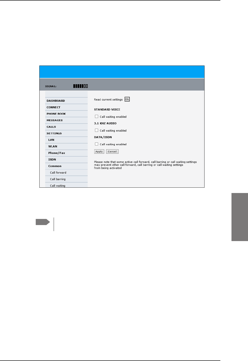
To set up the interfaces
98-127093-H Chapter 6: Configuration of the AVIATOR 200/300/350 system 6-31
6666
Call waiting
You can set up whether or not you want to receive notification of waiting calls while you
are making a call or transmitting data.
To receive a notification of waiting calls do as follows:
1. Select SETTINGS > Common > Call waiting from the left navigation pane.
Figure 6-25: Web interface: Settings, Common, Call waiting
2. Click OK next to Read current settings. A message saying Operation in progress,
please wait. is displayed.
Allow sufficient time for the system to read the current settings over the
satellite connection.
3. For each call type, select Call waiting enabled if you want to get notification of
waiting calls while you are making a call or transmitting data.
4. Click Apply.
Note
SB-Lite.book Page 31 Tuesday, September 5, 2017 1:38 PM
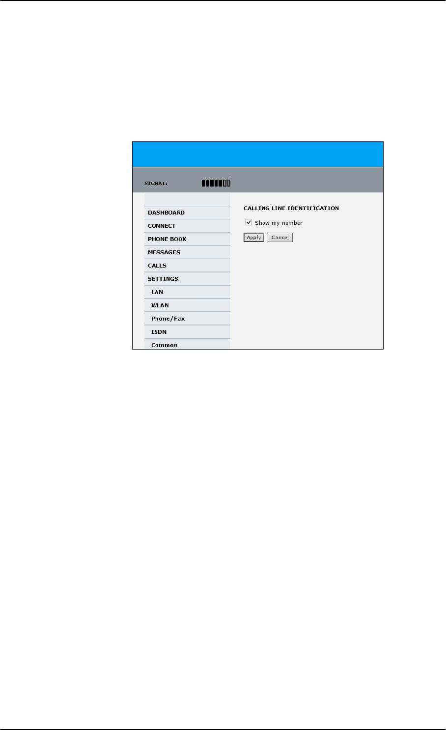
To set up the interfaces
6-32 Chapter 6: Configuration of the AVIATOR 200/300/350 system 98-127093-H
Line identification
You can set up the terminal to show your number when you are making a call or
transmitting data. The number shown is the standard voice number of the airtime
subscription.
To show the number when making a call or transmitting data do as follows:
1. Select SETTINGS > Common > Line identification from the left navigation pane.
Figure 6-26: Web interface: Settings, Common, Line identification
2. Select Show my number and click Apply.
SB-Lite.book Page 32 Tuesday, September 5, 2017 1:38 PM
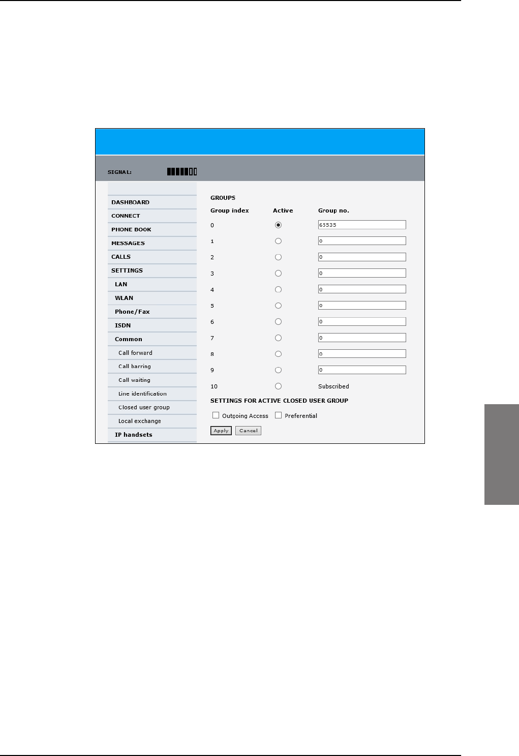
To set up the interfaces
98-127093-H Chapter 6: Configuration of the AVIATOR 200/300/350 system 6-33
6666
Closed user group
Your subscription may include one or more closed user groups. A closed user group is a
group of users permitted to make calls to each other but not to users outside the group. To
define the settings for these user groups, do as follows:
1. Select SETTINGS > Common > Closed user group from the left navigation pane.
Figure 6-27: Web interface: Settings, Common, Closed user group
2. Type in your user group number(s) under Group no.
Your airtime subscription lists your user group number(s).
3. Select which group(s) should be active.
If you select Active for Subscribed, the group(s) included in your subscription will be
active.
4. To allow outgoing access for the activated user group(s), select Outgoing Access
under SETTINGS FOR ACTIVE CLOSED USER GROUP. Note that if you selected
Subscribed above, this setting will not be used.
5. Select Preferential if you want the activated user group to be selected when a
member of a user group does not specify the group number during call set up. Note that
if you selected Subscribed above, this setting will not be used.
6. Click Apply.
SB-Lite.book Page 33 Tuesday, September 5, 2017 1:38 PM

To set up the interfaces
6-34 Chapter 6: Configuration of the AVIATOR 200/300/350 system 98-127093-H
Local exchange
If you want to call a specific phone connected to the terminal, use the local exchange
function. With this function enabled, when you dial the mobile number of the terminal, a
recorded message instructs you to dial the number for the local phone you want to call.
Your call is then transferred to the requested phone and only the requested phone rings. If
the local exchange is not used, incoming calls will per default cause all connected phones to
ring.
The Local exchange function is not available if you have enabled the Multi-voice
option.
For a detailed description how to set up the local exchange function of the SBU from a
remote location see the AVIATOR 200/300/350 user manual.
6.5.9 Manage AVIATOR Wireless Handsets
Overview
The SBU uses WLAN to connect AVIATOR Wireless Handsets or other IP equipment. The
AVIATOR 200/300/350 supports connection of up to 16 AVIATOR Wireless Handsets.
Each handset must have a local number in the range 0501 to 0516 as well as a unique
password.
The handset with the local number 0501 is the master handset. This means you
can start/stop data sessions from the SBU with this handset, if the function is
allowed in the User permissions page. See Set up user permissions on page 6-87
for further information on user permissions.
Connect a new AVIATOR Wireless Handset
Do as follows:
1. Connect the handset to the WLAN interface of the SBU. For a step-by-step procedure
see the AVIATOR Wireless Handset and Cradle User Manual, section Connecting the
AVIATOR Wireless Handset to a wireless access point.
2. When the handset display shows in the upper right corner, the handset is ready
to make a call. If you want to configure the handset or change the password, see the
next section.
When the SBU and the AVIATOR Wireless Handset have recognized each other, a
Configure link appears next to the handset in the IP handsets page of the web interface.
This link provides direct access to the built-in web interface of the AVIATOR Wireless
Handset. For further information, refer to the AVIATOR Wireless Handset and Cradle User
Manual.
Note
Note
Note By default, a handset connected to the WLAN interface on the terminal is
automatically registered in the terminal and assigned the first available local
number.
SB-Lite.book Page 34 Tuesday, September 5, 2017 1:38 PM
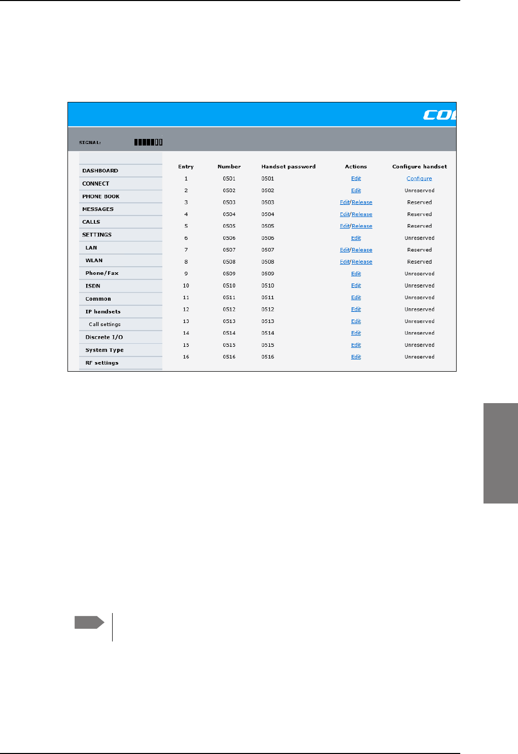
To set up the interfaces
98-127093-H Chapter 6: Configuration of the AVIATOR 200/300/350 system 6-35
6666
Set up the AVIATOR Wireless Handset
To set up an AVIATOR Wireless Handset, do as follows:
1. Select SETTINGS > IP handset.
Figure 6-28: Web interface: Settings, IP handsets
2. Select Edit next to a handset to change the password of the handset.
Remember that you must enter the same password and local number (user name) in the
handset. Use the display menu system to enter the local number and the password you
just entered in the web interface. Do as follows:
1. Enter the menu system and select SIP to get the list of profiles.
2. Select the BGAN profile and select Options.
3. Select Edit/View and change the user name and password.
Note that the user name is also the local number for the handset.
3. If you want to remove a handset from the list, click Release under Actions (the
Release link only appears when the handset is disconnected).
When a handset is removed from the list, you can no longer access the SBU with this
handset.
4. Select Configure next to a handset to access the built-in web interface of the
AVIATOR Wireless Handset.
The web interface of the handset opens. It is very similar to the web interface of the
SBU, but has a handset icon in the top left corner.
With the web interface of the IP handset you can access the internal settings of the
handset. For further information, refer to the AVIATOR Wireless Handset and Cradle
User Manual.
Note You can only access the web interface of the handset if Web server is enabled
under Settings > Web server in the handset menu (default enabled).
SB-Lite.book Page 35 Tuesday, September 5, 2017 1:38 PM
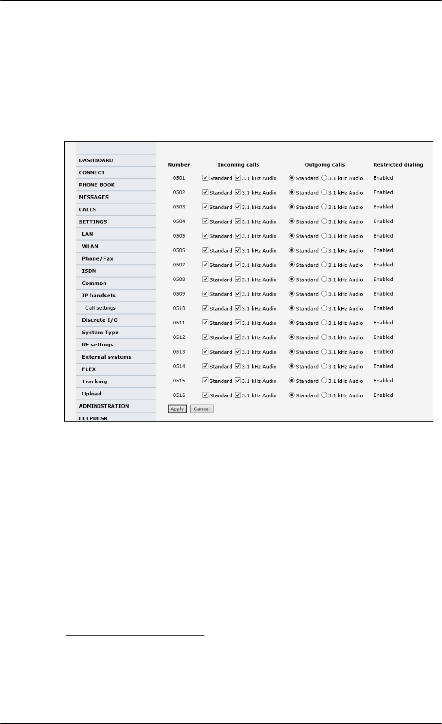
To set up the interfaces
6-36 Chapter 6: Configuration of the AVIATOR 200/300/350 system 98-127093-H
Set the call types for AVIATOR Wireless Handsets
On this page you set the call type and you can see whether Restricted dialing is enabled
for each handset. For information how to set up restricted dialing see the
AVIATOR 200/300/350 user manual.
To set the call types for AVIATOR Wireless Handsets, do as follows:
1. Select SETTINGS > IP handsets > Call settings.
Figure 6-29: Web interface: Settings, IP handsets, Call settings
2. For each handset, select the call types you want to enable for incoming and outgoing
calls.
The call types are described in more detail in the User Manual.
•For Incoming calls, you can check Standard or 3.1 kHz Audio or both. If you check
both, the handset will react (ring) on any incoming call. Example: If you select
Standard, the handset will only react on calls made to the Standard phone number.1
• For Outgoing calls, you can select either Standard or 3.1 kHz Audio. The selected
type will be used by default, if possible, for any outgoing call.
3. Click Apply.
1.If Multi-voice is enabled and you have entered additional numbers in the phone book,
you can assign an additional number to each IP handset. For more information see
Multi-voice (option) on page 6-91.
SB-Lite.book Page 36 Tuesday, September 5, 2017 1:38 PM

To set up the interfaces
98-127093-H Chapter 6: Configuration of the AVIATOR 200/300/350 system 6-37
6666
6.5.10 Configure the discrete I/O interfaces
Overview
The SBU has 4 annunciators, 1 chime/lamp inhibit and 5 non-configurable discrete inputs.
The non-configurable discrete inputs are SBU nOn (remote on/off), SBU Enable, WLAN
Enable and two for Automatic Test Equipment (ATE). The ATE inputs are only for factory
use, do not connect them.
Each I/O pin that can be configured is displayed in the web interface. For more information
on the pins TP (Top Plug) and BP (Bottom Plug) see Pin-out for SBU rear receptacle (top
plug) on page 4-7 and Pin-out for SBU rear receptacle (bottom plug) on page 4-8.
The functions of the I/O pins are as follows:
• Pin TP13: Input. Chime/Lamps Inhibit Input.
This discrete input is used to inhibit Satcom activation of the chime and call lights
during take-off and landing.
• Pin TP27: Output. Annunciator #3 “Service Available”.
Default behavior: Active low when the SwiftBroadband Service is logged on
• Pin TP28: Output. Annunciator #1 “Incoming call”.
Default behavior: Active low when a handset is ringing.
• Pin TP29: Output. Annunciator #2 “SBU Failed”.
Default behavior: Active low whenever a BITE with severity essential or fatal is active on
the SBU.
• Pin BP1: Output. Annunciator #4 “Message received”
This discrete output can be used to indicate that there is an unread message in the SBU.
Default behavior: Active low.
SB-Lite.book Page 37 Tuesday, September 5, 2017 1:38 PM
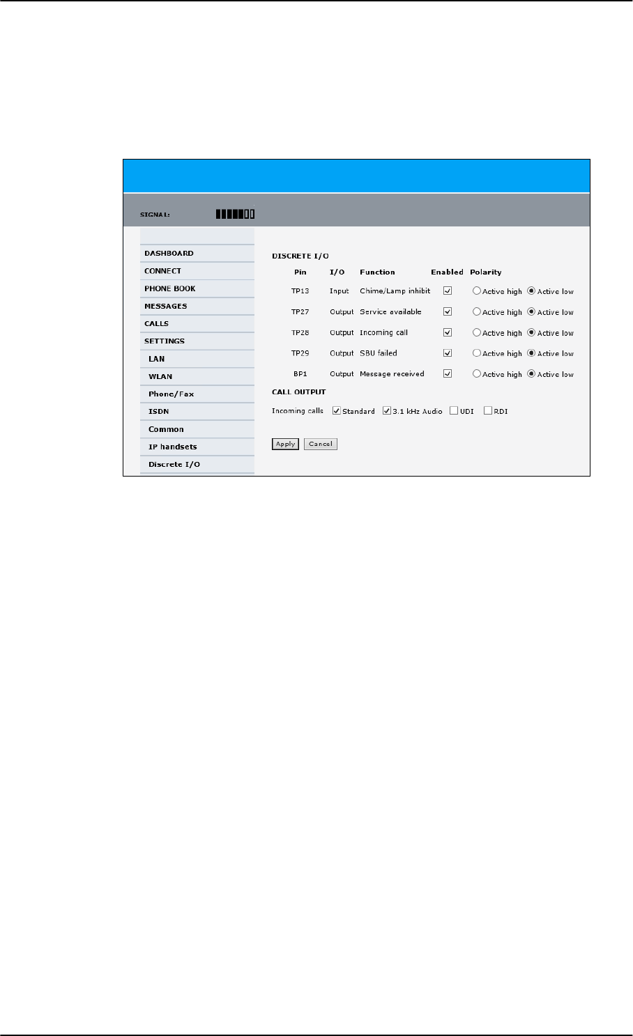
To set up the interfaces
6-38 Chapter 6: Configuration of the AVIATOR 200/300/350 system 98-127093-H
Set the discrete I/O interfaces
You can enable and set some of the discrete I/Os in the web interface. To set these, do as
follows:
1. Select SETTINGS > Discrete I/O.
Figure 6-30: Web interface: Settings, Discrete I/O (without SB-Safety Voice)
2. For each pin you want to use, select Enabled.
3. For each pin, select if the pin should be Active high or Active low.
4. For Call output you can select which incoming calls will activate the external ringer
(Discrete I/O TP28: Incoming call).
5. Click Apply to save the new settings.
Set the discrete I/O interfaces for SB-Safety Voice
When SB-Safety Voice is enabled, the following changes apply:
• Pin TP13 Chime/Lamps Inhibit also disables ringing on the 2-wire handset.
• Pin TP27 Service Available must be inverted to indicate failure of Voice service (connect
to SBB FAIL light)
• Pin TP14 is Call Priority 1 annunciator.
• Pin BP4 is Call Priority 2 annunciator.
• Pin BP2 is Call Priority 3 annunciator.
SB-Lite.book Page 38 Tuesday, September 5, 2017 1:38 PM
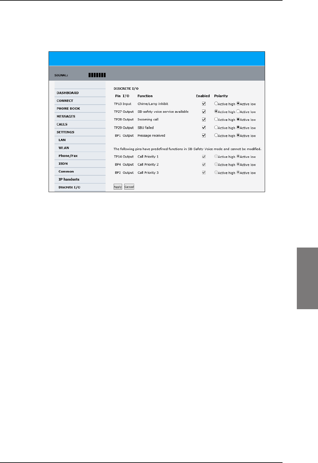
To set up the interfaces
98-127093-H Chapter 6: Configuration of the AVIATOR 200/300/350 system 6-39
6666
To set the discrete I/Os in the web interface, do as follows:
1. Select SETTINGS > Discrete I/O.
Figure 6-31: Web interface: Settings, Discrete I/O (with SB-Safety Voice)
Pin TP27 Service Available must be inverted to indicate failure of Voice service (connect to
SBB FAIL light).
6.5.11 Set the system type
During the initial configuration of the system you must assign the system type, that is the
AVIATOR 200/300/350 system that you have bought. You can typically only select the
system type purchased. The Reset functionality is mainly used for support purposes or
when the system type is changed. For systems with SB-Safety Voice (software 4.00 or
higher) see the separate section SB-Safety Voice (option) on page 6-55.
SB-Lite.book Page 39 Tuesday, September 5, 2017 1:38 PM
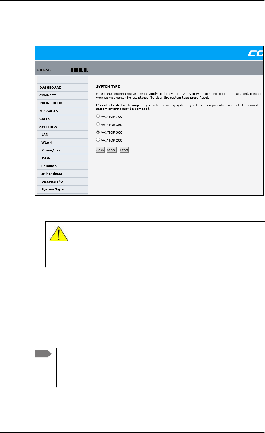
To set up the interfaces
6-40 Chapter 6: Configuration of the AVIATOR 200/300/350 system 98-127093-H
To select the system type, do as follows:
1. Select SETTINGS > System Type.
Figure 6-32: Web interface: Settings, System type
2. Select the system type for the installation.
Do not try to use a different system type!
3. Click Apply to save the new setting.
Changing the system type
You can change the system type if there are major changes to the installation (like
upgrading from an IGA antenna to an HGA antenna) or the satcom system is moved from
one plane to another.
You can replace the SBU, HLD or the satcom antenna (same type) without the
need to reconfigure the system. This is possible because all system settings are
stored in the Configuration Module. Therefore there is no need to select a new
system type when replacing the SBU, HLD or the satcom antenna (same type). For
instructions how to remove the SBU alone see Inoperative units on page 7-1.
CAUTION! Selecting a wrong system type may cause damage to the
satcom antenna or GPS antenna. If the system type purchased can not be
selected, please contact the supplier of your AVIATOR 200/300/350
system.
Note
SB-Lite.book Page 40 Tuesday, September 5, 2017 1:38 PM
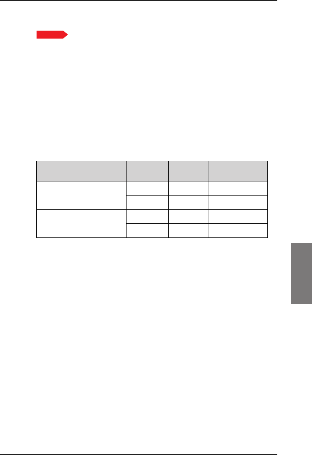
To set up the interfaces
98-127093-H Chapter 6: Configuration of the AVIATOR 200/300/350 system 6-41
6666
Before upgrading with a new antenna type or removing the satcom system do as follows:
1. Select SETTINGS > System Type.
2. Click Reset to erase the system type and all settings from the pages RF Settings and
External systems.
3. Power off the system and make the necessary changes (install new antenna or move
the entire satcom system).
If changing the system type directly without clicking the Reset button, the contents of the
pages RF Settings and External systems are erased and must be entered again. This
does not apply when changing between AVIATOR 300 and AVIATOR 350, in which case
only the antenna type is erased.
Table 6-2: Changing the System type, use of Reset button
Changing the system type Click the
Reset button
Values in
RF Settings
Values in External
systems
AVIATOR 300 to AVIATOR 350 No Not cleared Not cleareda
a. Note that the field ANTENNA Type on the page SETTINGS > External systems is cleared.
Yes Cleared Cleared
AVIATOR 200 to AVIATOR 350 No Cleared Cleared
Yes Cleared Cleared
Important To avoid potential damage to the satcom or GPS antenna, it is strongly
recommended to follow this procedure before you remove the satcom
system from one plane for installation in another
SB-Lite.book Page 41 Tuesday, September 5, 2017 1:38 PM

To set up the interfaces
6-42 Chapter 6: Configuration of the AVIATOR 200/300/350 system 98-127093-H
Upgrading AVIATOR 300 to AVIATOR 350
To upgrade an AVIATOR 300 system with IGA antenna to an AVIATOR 350 system with
HGA antenna, use the following procedure to change the system type:
1. Select SETTINGS > System Type.
2. Select AVIATOR 350.
3. Click Apply.
4. Continue with the setup of the navigational input, for information on how to configure
the antenna see Set up the navigational input on page 6-44.
When upgrading the antenna, it is often necessary to reconfigure the cable
loss (see Configure RF settings on page 6-43) and the navigational input (see
Set up the navigational input on page 6-44).
Important
SB-Lite.book Page 42 Tuesday, September 5, 2017 1:38 PM
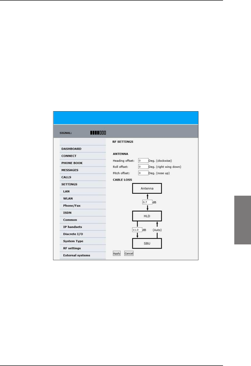
To set up the interfaces
98-127093-H Chapter 6: Configuration of the AVIATOR 200/300/350 system 6-43
6666
6.5.12 Configure RF settings
Before you can configure the RF settings you must select the system type.
You must configure the AVIATOR 200/300/350 installation with the specific cable losses of
the installation. For AVIATOR 300 and AVIATOR 350 you can also enter heading, roll and
pitch offset of the satcom antenna of the installation, if the antenna for any reason is
installed in a position that deviates from the position recommended in the installation
instructions, i.e. the position is not aligned with the aircraft.
To configure the RF settings, do as follows:
1. Connect to the Maintenance connector on the front panel of the SBU and enter the
web interface (default: http://192.168.0.1)
2. From the left navigation pane select SETTINGS > RF settings.
Figure 6-33: Web interface: Settings, RF settings
3. Below Antenna insert in Heading Offset: Deg. (Clockwise), Roll Offset: Deg. (Right
Wing Down) and Pitch Offset: Deg. (Nose up) the degrees by which the current
installation deviates from the antenna position recommended in the antenna
installation instructions. These settings are greyed out for the AVIATOR 200.
4. Below CABLE LOSS enter the cable loss for the cables between the
• Antenna and the HLD, allowed range for AVIATOR 200: 0 to 0.3 dB,
for AVIATOR 300 and AVIATOR 350: 0 to 0.7 dB
• HLD and the SBU, allowed range for AVIATOR 200: 0 to 17 dB,
for AVIATOR 300 and AVIATOR 350: 0 to 20 dB
5. Click Apply to save the new settings.
SB-Lite.book Page 43 Tuesday, September 5, 2017 1:38 PM
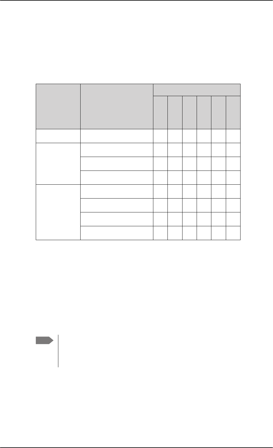
To set up the interfaces
6-44 Chapter 6: Configuration of the AVIATOR 200/300/350 system 98-127093-H
6.5.13 Set up the navigational input
Before you can configure the navigational input you must select the system type.
The AVIATOR 200/300/350 supports input from several sources to retrieve navigational
information, depending on the installed satcom antenna type. The following table gives an
overview of the supported navigational input sources for the different satcom antenna
types.
Table 6-3: Navigational input for system types and satcom antennas
System type Satcom antenna type
Navigational input
IRS
AHRS+GPS
NRS
NPI
GNSS
GPS only
AVIATOR 200 TT-3002A LGA/LGA-3000 X X X X
AVIATOR 300 TT-5006A IGA X X X
IGA-5001 X X
AMT-3800 X X
AVIATOR 350a
a. AVIATOR 350 can also be used with TT-5006 IGA or IGA 5001, then the system
is an AVIATOR 300.
HGA-6000/HGA-6500 X X
HGA-7000/HGA-7001 X X
AMT-50/700/3800 X X
CMA-2102/CMA-2102SB X X
For further information on supported navigational systems see About satcom antenna
steering for IGA and HGA (AVIATOR 300 and AVIATOR 350) on page 5-4.
When using IRS, AHRS, NPI or GNSS, ARINC 429 Speed can individually be set to high or
low speed on the primary and secondary input, depending on your configuration. For
redundancy reasons the system supports a secondary source, in case the primary source
fails.
To set up the navigational input, do as follows:
1. Connect to the Maintenance connector on the front panel of the SBU and enter the
web interface (default address: http://192.168.0.1)
Note If you use IRS, AHRS, NPI or GNSS, make sure that you configure the primary and
secondary IRS or AHRS to the correct speed in your configuration. This is essential
to provide the necessary navigation data needed for the correct positioning of the
antenna.
SB-Lite.book Page 44 Tuesday, September 5, 2017 1:38 PM
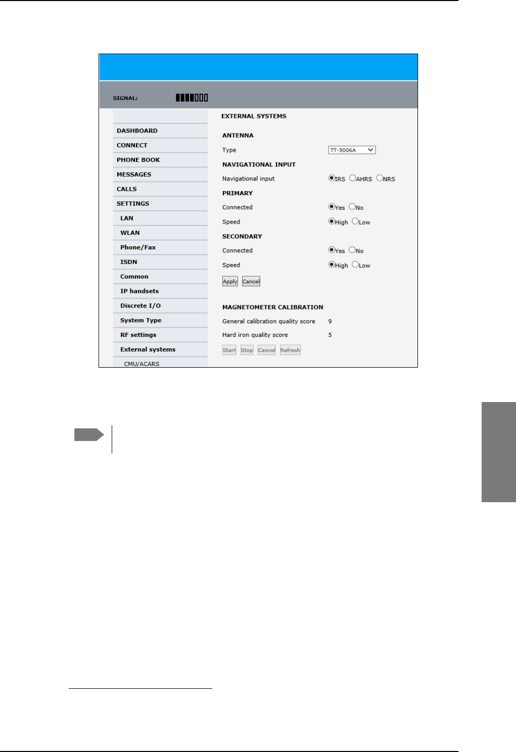
To set up the interfaces
98-127093-H Chapter 6: Configuration of the AVIATOR 200/300/350 system 6-45
6666
2. From the left navigation pane select SETTINGS > External systems.
Figure 6-34: Web interface: Settings, External systems (AVIATOR 350 with TT-5006 antenna)
3. Below Antenna select in the drop down list the connected antenna. See Table 6-3 on
page 6-44 for available selections.
Check in Table 6-7 on page 6-51 that CMU/ACARS is disabled for antennas
supporting BSU.
4. For NAVIGATIONAL INPUT select one option. Which options are available depends
on the installed antenna, see Table 6-3 on page 6-44.
5. Only for ARINC sources1: For Primary and Secondary select Connected and Speed.
6. Only for ARINC sources: If you do not have second navigational input source available
you must set Connected of SECONDARY input to No.
7. Only AHRS+GPS and GPS only: GPS VOLTAGE is needed if you have selected
AHRS+GPS as a navigation source and HGA-6000 or AMT-50 as an antenna. In this case
you have a separate GPS antenna that needs to be powered by the SBU. Use GPS
VOLTAGE to set the voltage to the correct value for the GPS antenna.
It is not used for the TT-5006A antenna. The TT-5006A antenna has an integrated GPS
antenna, then you do not need to set the GPS voltage.
8. Click Apply to apply the new settings.
Note
1. ARINC sources are IRS, AHRS + GPS, GNSS and NPI.
SB-Lite.book Page 45 Tuesday, September 5, 2017 1:38 PM

To set up the interfaces
6-46 Chapter 6: Configuration of the AVIATOR 200/300/350 system 98-127093-H
9. MAGNETOMETER CALIBRATION
This is only necessary for TT-5006A IGA and NRS selected.
If you use the satcom antenna TT-5006A with NRS you must do a MAGNETOMETER
CALIBRATION to compensate for potential magnetic interference on the
navigational input signal. This procedure is described in the following section Calibrate
the NRS magnetometer in the TT-5006A IGA.
For an overview of the supported navigational input sources for the different satcom
antennas see Table 5-2 on page 5-4.
6.5.14 Calibrate the NRS magnetometer in the TT-5006A IGA
For a system with a TT-5006A IGA you can use the built-in NRS if no IRS/AHRS are
available.
The NRS system consists of a 3D magnetometer, a pitch sensor and a GPS receiver. The
magnetometer measures the strength and direction of the magnetic field (the magnetic
vector), and compares is to what is expected at the current GPS position (values from a
database). Based on these values, the orientation of the aircraft can be calculated.
For the NRS system to work properly, it is essential that the magnetic environment around
the TT-5006A antenna is without too much magnetic influence from the aircraft. If
magnetic sources are present (e.g. loudspeakers, iron screws, nuts etc.), remove these or
encapsulate them as much as possible.
Remaining magnetic influence can be compensated for by means of the calibration
procedure. Note that the calibration can only be used to compensate for influence from
STATIC magnetic components. If the magnetic influence is from a source which may vary,
e.g. a DC-current in a cable running near the antenna, then a change in the current will make
the calibration inaccurate.
When using NRS, you must calibrate the integrated magnetometer to compensate for
potential magnetic interference. During the calibration, data is collected about the
orientation of the antenna installation on the aircraft (pitch, roll and heading offset) and
about local magnetic fields. A proper calibration is essential to track the satellites correctly.
Failure to calibrate the system may cause the system not to work properly.
Note that you must repeat the calibration procedure if you exchange the antenna or if the
magnetic environment inside the aircraft changes (mounting of loudspeakers close to the
satcom antenna etc.). The calibration data is stored in the CM.
You start and stop the magnetometer calibration procedure using a PC connected to the
maintenance connector of the SBU and the web interface.
Note
SB-Lite.book Page 46 Tuesday, September 5, 2017 1:38 PM
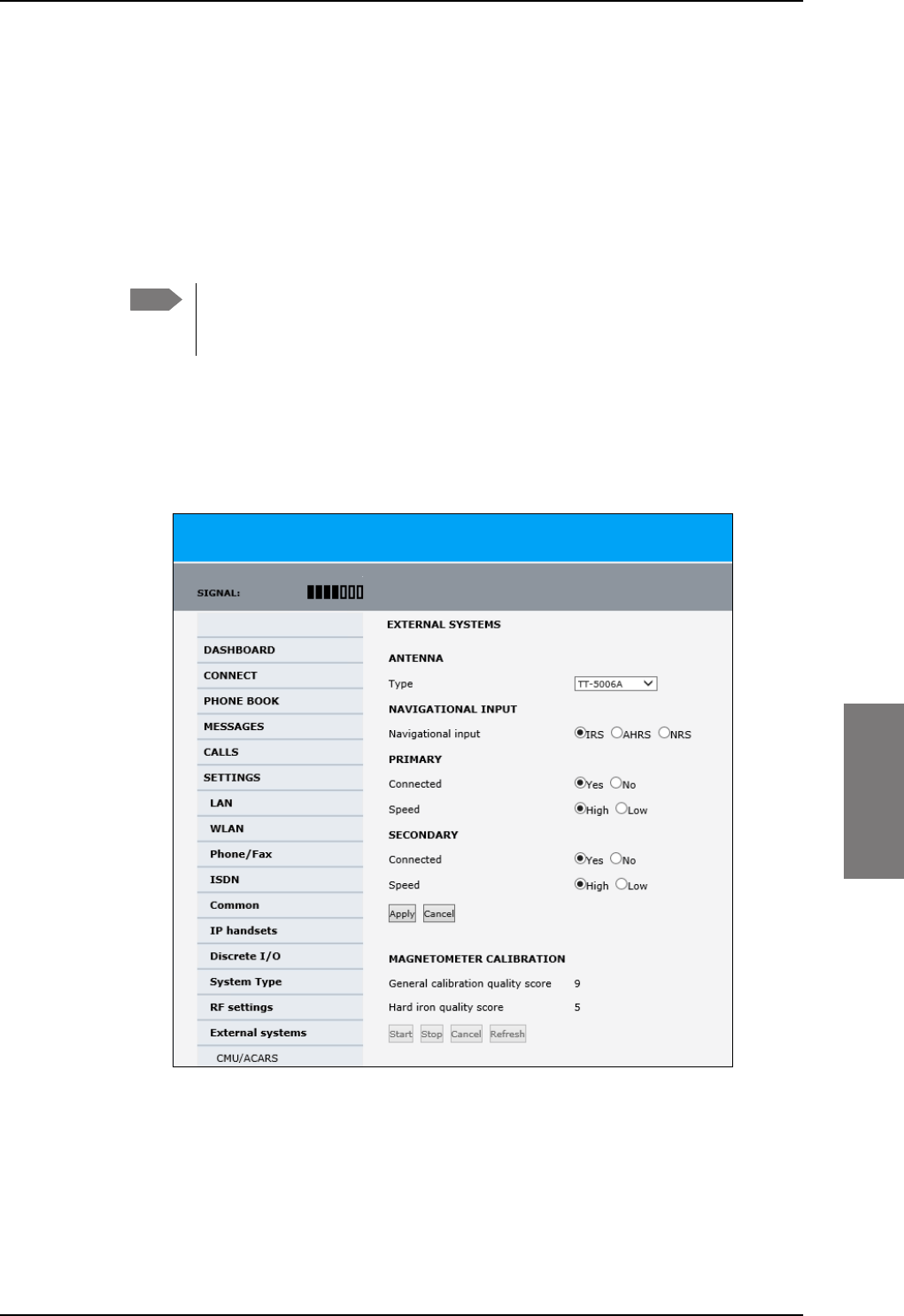
To set up the interfaces
98-127093-H Chapter 6: Configuration of the AVIATOR 200/300/350 system 6-47
6666
Magnetometer calibration procedure
To calibrate the magnetometer do as follows:
1. Connect a PC to the Maintenance connector of the SBU and enter the web interface.
2. Find a suitable location where the AVIATOR system can obtain GPS synchronization
and where there is sufficient space for the aircraft to complete a turn of at least 360°.
Make sure that a full circle of 360° is covered, 370° is fine too. 350° is not sufficient to
produce a valid calibration result.
Make sure that the aircraft is away from large buildings or vehicles which could
disturb the terrestrial magnetic field. Preferably use the compass calibration
field in the airport area.
3. Power up all aircraft systems, including the engines. This is to create the aircraft
magnetic environment as it is in in-flight condition.
4. Wait until the GPS of the aircraft is operational. Check on the page DASHBOARD
whether the field GPS position shows a valid value.
5. From the left navigation pane select SETTINGS > External systems.
Figure 6-35: Web interface: Settings, External systems, Magnetometer Calibration
6. Advise the pilot to make a slow 360° circle on a smooth, flat, and level surface. Make
sure that the turn rate is between 1 and 2° per second, i.e. one circle should take
minimum 3 minutes, maximum 10 minutes, to produce valid calibration results. Keep
Note
SB-Lite.book Page 47 Tuesday, September 5, 2017 1:38 PM
To set up the interfaces
6-48 Chapter 6: Configuration of the AVIATOR 200/300/350 system 98-127093-H
the movement as even as possible, avoid sudden movements or changes in speed. The
start direction of the turn is not relevant.
It is recommended for the calibration to succeed, that the turn is performed in
a constant direction. If the aircraft e.g. turns a bit counterclockwise before
completing a full turn clockwise, this might bring the calculations of calibration
parameters to fail. Make the turn radius as small as possible.
7. In the section for magnetometer calibration click the button Start to start the
calibration procedure.
When a calibration is completed successfully, any previously stored
calibration data is overwritten without further notice.
8. When a turn is complete, click Stop. The system initiates a calculation in the
background that may take between 10 seconds and a few minutes.
Click optionally the button Refresh until the result is shown. The resulting calibration
score is shown as two digits.
9. See the following table for guidelines how to evaluate the calibration score.
Note
Important
Calibration quality score Hard iron interference calibration score
9: Good
8: Good
7: Good
6: Acceptable
5: Acceptable
4: Marginal
3: Marginal
2: Unacceptable
1: Unacceptable
0: Unacceptable
9: <10% Good
8: <20% Good
7: <30% Good
6: <40% Acceptable
5: <50% Acceptable
4: <60% Acceptable
3: <70% Investigate
2: <80% Investigate
1: <90% Investigate
0: >90% Investigate
Table 6-4: Evaluation of the magnetometer calibration score
SB-Lite.book Page 48 Tuesday, September 5, 2017 1:38 PM

To set up the interfaces
98-127093-H Chapter 6: Configuration of the AVIATOR 200/300/350 system 6-49
6666
Investigate a low Hard Iron score
The hard iron score is an indication of how much magnetic flux (Tesla) the magnetometer
inside the antenna has measured, compared to what was expected at the current latitude
and longitude based on the Earth's magnetic model stored inside the SBU. In other words, it
is an indication of how big a static magnetic disturbance is present from the aircraft
structure itself (magnetic screws etc.).
The lower the number, the more unwanted flux and the more difficult it will be for the
system to correctly calculate heading, pitch and roll. While a high hard iron score is not a
strict requirement, since the purpose of the calibration is to map this disturbance so it can
be compensated for later, a low score should always be investigated and fixed if possible:
1. Confirm that non-magnetic screwdrivers and non-magnetic screws were used for the
antenna installation.
2. Ensure that any nearby speakers in the cabin have been properly shielded.
3. Ensure that nearby metallic objects do not interrupt the calibration.
DC cables with high current will also generate flux and can cause low hard iron score.
All though the calibration procedure is done to counter this unwanted magnetic flux, you
must determine if the disturbance comes from a wire where the current may change during
flight. If this DC current changes, the disturbance will also change, and hence the calibration
will no longer be accurate.
There are a couple of different ways to investigate hard iron disturbance. The area around
the antenna can be surveyed with a simple Boy Scout compass, making sure there is only a
slight deflection of the needle, when the compass is moved to and from and around the
antenna. If there are more than 10-15 degrees, investigate what the cause is.
Another way is to use the values from the magnetometer inside the antenna itself. This is
especially useful if you suspect disturbance from DC cables, e.g. from generators, which can
be impractical to measure outside the aircraft, with engines running. These values can be
read out once at a time via the command line with the stat -m tt5006a command or printed
every second with the following two commands:
• trace -m tt5006A:cno -c 1 set <enter>
• console_set <enter>
See Appendix G, Terminal commands, for information on how to use terminal commands.
The magnetometer gives 3 values named Bx, By and Bz, shown in nT (nano Tesla).
Monitor these values, while high current systems with cables near the antenna are turned
on and off, and make sure the values don't vary significantly. If they do, reroute the cables
to make the NRS work reliable.
SB-Lite.book Page 49 Tuesday, September 5, 2017 1:38 PM
To set up the interfaces
6-50 Chapter 6: Configuration of the AVIATOR 200/300/350 system 98-127093-H
Error messages during magnetometer calibration
Error messages at failing
START procedure How to proceed
Failure due to missing
GPS satellite fix.
Wait some time to get a GPS fix, check that there is free line of
sight to GPS satellites, i.e. the plane must be outside the hangar.
Check on the page DASHBOARD whether the field GPS
position shows a valid value.
Could not obtain the
matrix of Earth’s
magnetic field.
Restart the system. If the error persists, contact your Cobham
SATCOM partner’s support hotline or Cobham SATCOM e-
support.
Failure due to memory
exhaustion.
Restart the system. If the error persists, contact your Cobham
SATCOM partner’s support hotline or Cobham SATCOM e-
support.
Could not
communicate with
antenna.
Check the satcom antenna and cables to the satcom antenna.
Unknown start error. Restart the system. If the error persists, contact your Thrane &
Thrane partner’s support hotline or Thrane & Thrane e-support.
Table 6-5: Magnetometer calibration: Error messages at failing Start procedure
Error messages at failing
STOP procedure How to proceed
Calibration stopped
outside allowed time
interval (min. 3 minutes,
max. 10 minutes).
Rerun the calibration within the allowed time interval.
Calibration
convergence error,
possibly due to the
aircraft being rotated
less than 360 degrees.
Rerun the calibration within the allowed time interval.
Unknown calibration
error.
Rerun the calibration. Try to follow the instructions how to
perform the 360° turn more carefully. If this does not help,
restart the system. If the error persists, contact your Cobham
SATCOM partner’s support hotline or Cobham SATCOM e-
support.
Table 6-6: Magnetometer calibration: Error messages at failing Stop procedure
SB-Lite.book Page 50 Tuesday, September 5, 2017 1:38 PM
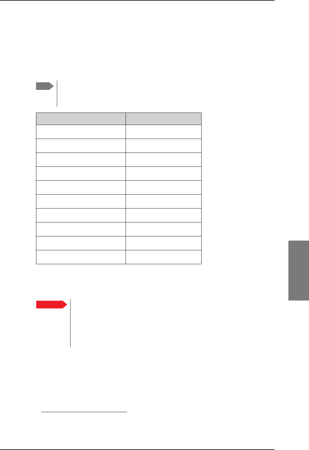
To set up the interfaces
98-127093-H Chapter 6: Configuration of the AVIATOR 200/300/350 system 6-51
6666
6.5.15 Set up CMU/ACARS (option)
The AVIATOR 200/300/350 supports ACARS communication over Swift Broadband. The
connection to the CMU uses the same A429 lines as the ACU/BSU of the antenna system or
an AIS 380 Aircraft Interface Module1, This option is only available with certain types of
antennas, i.e. antennas controlled via modem on the coax cable or LGAs without control.
For a list of antenna that support the CMU/ACARS option see the table below.
You must have SBU software version minimum AVIATOR 200/300/350 (Level E):
1.07, AVIATOR 200D/300D/350D (Level D): 2.01, in order to support the
CMU/ACARS option.
Table 6-7: Satcom antennas in AVIATOR systems supporting CMU
Satcom antenna system CMU support
TT-3002A/LGA-3000
TT-5006A
IGA-5001
AMT-50/700
AMT-3500
AMT-3800
HGA-6000/6500/7000
HGA-7001
HGA-8000
CMA-2102SB/2200SB
When using the SBU/ACARS interface for SBB Safety Services (e.g. CPDLC
traffic) note that additional user traffic and interface connections to the SBU
shall be addressed in the Security Safety Assessment (SSA) of the particular
aircraft. The SBU does not comply to the ARINC-781 attachment 8, Security
Considerations. There is no segregation between the user interfaces. All
interfaces of the SBU shall be considered as 'Aircraft Control Domain'.
The setup of CMU/ACARS is divided into 3 areas:
• ACARS Aircraft Gateway (AAGW)
• Aircraft
• ACARS Ground Gateway (AGGW)
1. For software version 2.03.
Note
Yes
Yes
Yes
Noa
a. CMU support possible with the converter RS-422 to A429
(AIS 380 Aircraft Interface Module)
Noa
Noa
Yes, if coax modem is used
Noa
Yes
Noa
Important
SB-Lite.book Page 51 Tuesday, September 5, 2017 1:38 PM
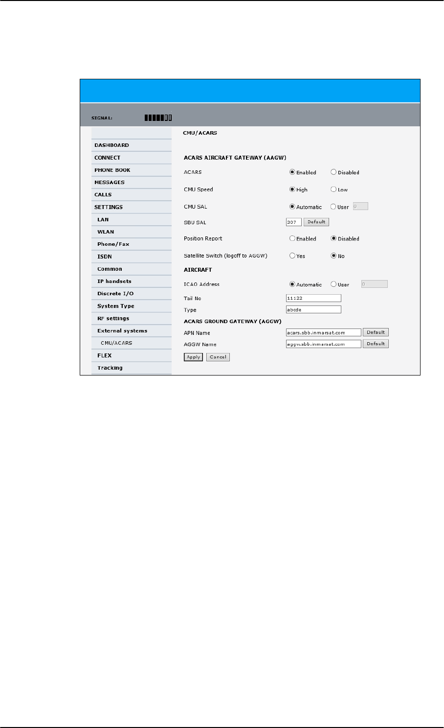
To set up the interfaces
6-52 Chapter 6: Configuration of the AVIATOR 200/300/350 system 98-127093-H
To set up CMU/ACARS, do as follows:
1. Select SETTINGS > External systems > CMU/ACARS.
Figure 6-36: Web interface: CMU/ACARS
2. At ACARS Select Enabled. Check in the table above that your system supports CMU.
3. At CMU Speed select High or Low, depending on the CMU.
4. At CMU SAL select Automatic (default) or User. Allowed octal range: 0-377. This
number is used for identification of the CMU in the installation.
5. At SBU SAL select Default or type in the number. Allowed octal range: 0-377. This
number is used for identification of the SBU in the installation.
6. At Position report you can select whether to include the aircraft’s GPS position to the
AGGW (Enabled) or not (Disabled).
7. At Satellite Switch you can select whether the hand over to the new satellite is done
after a logoff to the ACARS Ground Gateway (Yes) or the switch happens
instantaneously (No).
8. At ICAO Address you can select to send the aircraft’s address automatically or you
can enter it manually. Allowed octal range: 0-77777777
9. At Tail No and Type you can enter the aircraft’s tail number and type. You must at
least enter multiple blank spaces. These 2 fields cannot stay empty.
10. At APN Name and AGGW Name keep the default values or enter new data received
from your service provider.
11. Click Apply to save the settings.
SB-Lite.book Page 52 Tuesday, September 5, 2017 1:38 PM
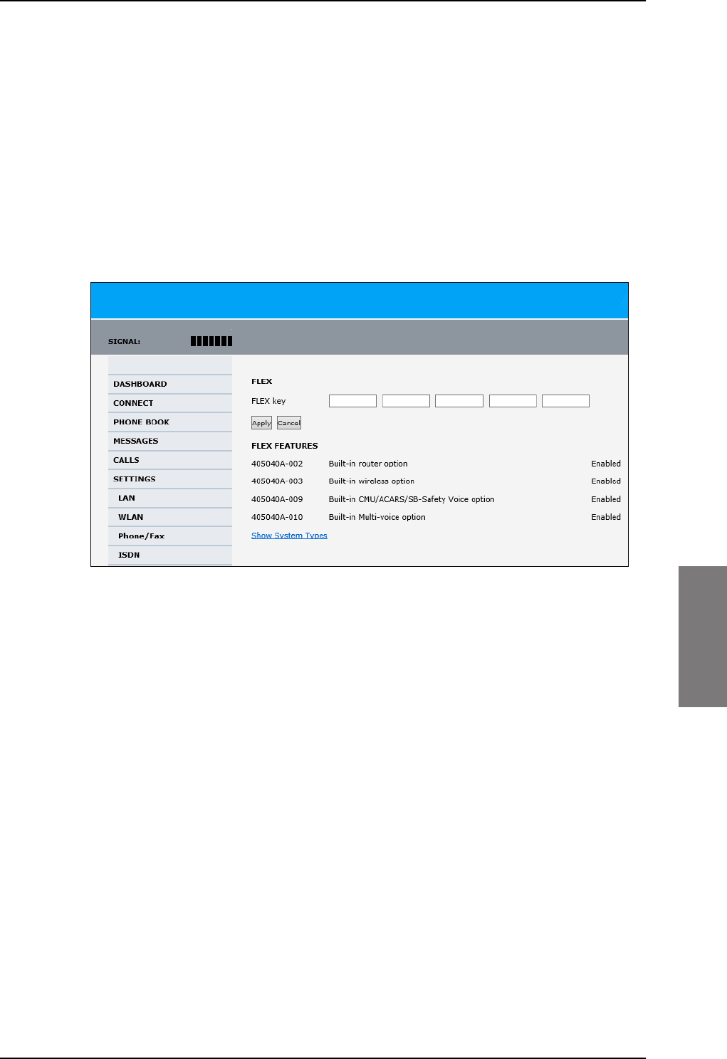
To set up the interfaces
98-127093-H Chapter 6: Configuration of the AVIATOR 200/300/350 system 6-53
6666
6.5.16 Enable system options with FLEX keys
On the FLEX page you can view the options for your system that are currently enabled or
disabled. Enabling the purchased options is typically done at the factory. You can buy
options at a later stage and open up for them by entering a FLEX key sequence for the
specific built-in option. The available options are listed in Table 2-6 on page 2-10.
To enable a built-in option, do as follows:
1. Connect to the Maintenance connector on the front panel of the SBU and enter the
web interface (default: http://192.168.0.1).
2. From the left navigation pane select SETTINGS > FLEX.
Figure 6-37: Web interface: Settings, FLEX (example)
3. Have the FLEX key ready and enter it into the insert fields.
4. Click Apply to enable the new option.
5. Click Show System Types to display the system types and their status (enabled or
disabled).
SB-Lite.book Page 53 Tuesday, September 5, 2017 1:38 PM
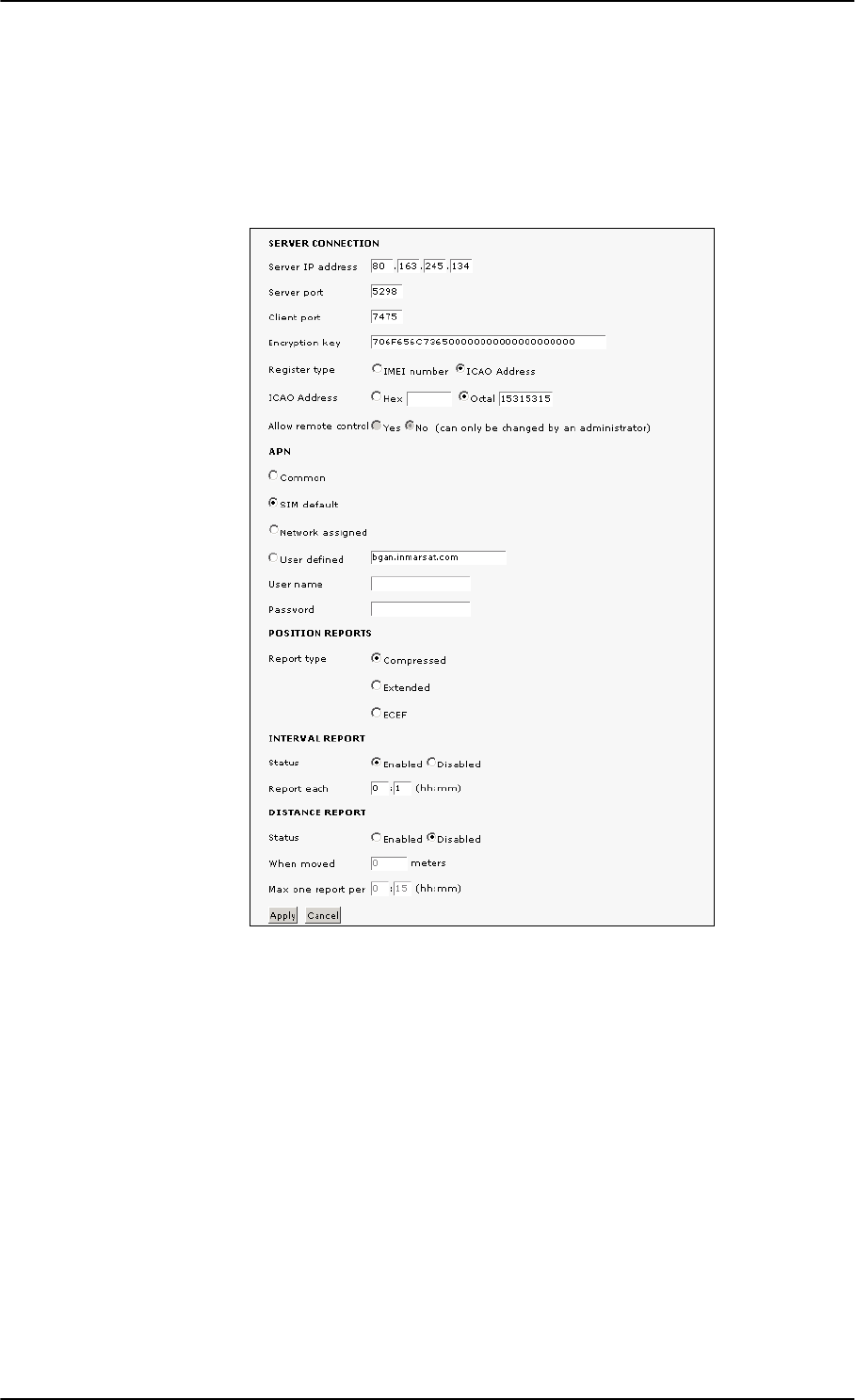
To set up the interfaces
6-54 Chapter 6: Configuration of the AVIATOR 200/300/350 system 98-127093-H
6.5.17 Tracking
With tracking you can set the SBU to send reports with current position information at
specified time intervals or distances to a server address. To set up tracking, do as follows:
1. Select SETTINGS, Tracking.
2. The information in the sections SERVER CONNECTION and APN must be provided
by your airtime provider.
3. In POSITION REPORTS you can select among the following:
•Compressed: Aircraft’s position with latitude and longitude.
•Extended: Aircraft’s position latitude, longitude, heading, speed and UTC time.
•ECEF: Aircraft’s position in x,y,z coordinates and a velocity vector.
4. In INTERVAL REPORT and DISTANCE REPORT you can enable the respective
report and set a report interval or distance.
5. Click Apply to save the settings.
Figure 6-38: Web interface, Settings, Tracking
SB-Lite.book Page 54 Tuesday, September 5, 2017 1:38 PM
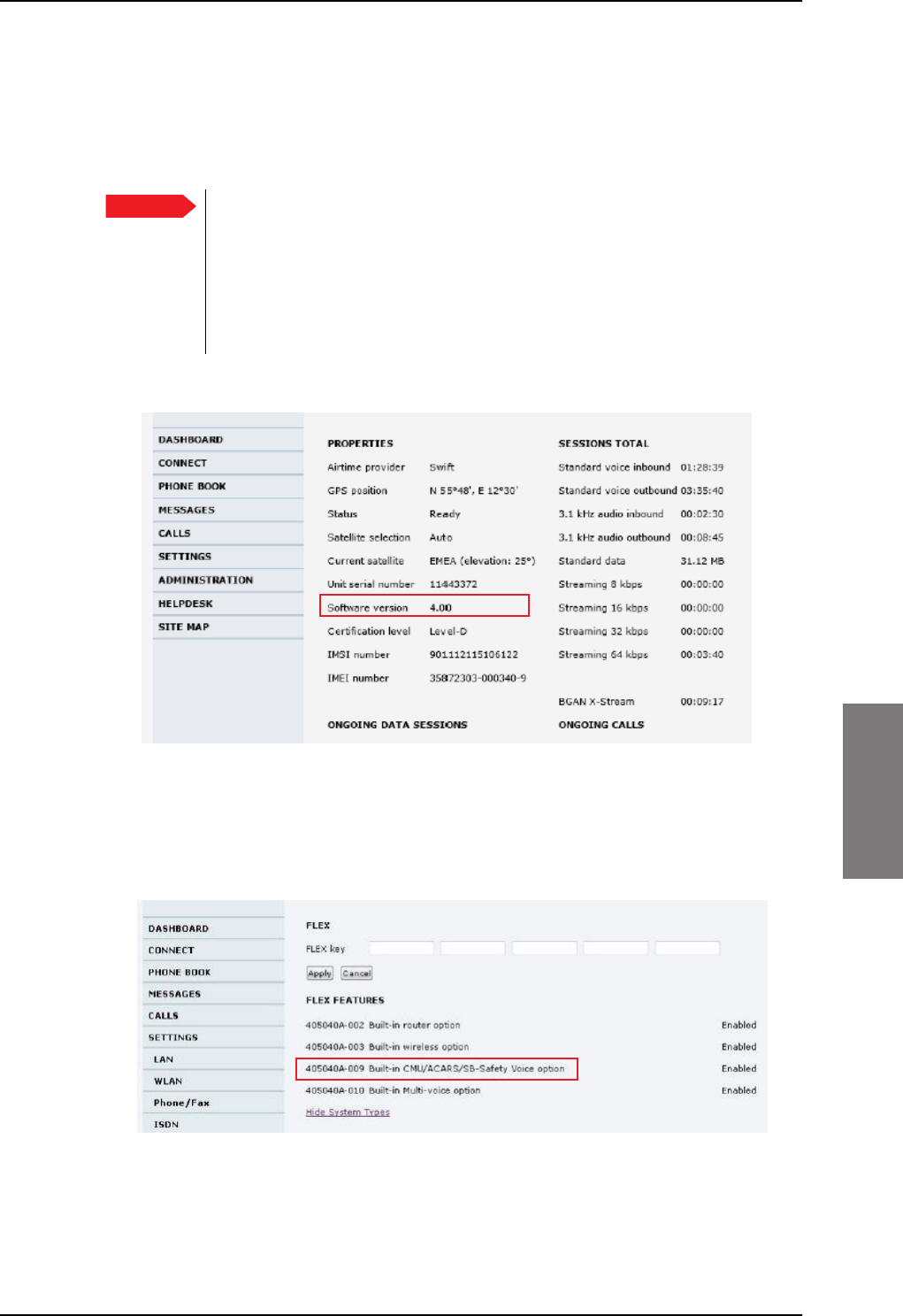
To set up the interfaces
98-127093-H Chapter 6: Configuration of the AVIATOR 200/300/350 system 6-55
6666
6.5.18 SB-Safety Voice (option)
To use the SB-Safety Voice service, the SBU must have software version 4.00 or higher.
Note that the POTS#1 configuration cannot be changed and the POTS#2 and ISDN are
forcibly disabled.
When using the SBU/ACARS interface for SBB Safety Services (e.g. CPDLC
traffic) and/or SB-Safety Voice is enabled, note that additional user traffic and
interface connections to the SBU shall be addressed in the Security Safety
Assessment (SSA) of the particular aircraft. The SBU does not comply to the
ARINC-781 attachment 8, Security Considerations. There is no segregation
between the user interfaces. All interfaces of the SBU shall be considered as
'Aircraft Control Domain'.
The software version is shown on the DASHBOARD.
Figure 6-39: Web interface, DASHBOARD software version 4.00
To set-up SB-Safety Voice, do as follows:
1. Check that the SBUhas software version 4.00.
2. Check that the option for Built-in ACARS/SB-Safety Voice is enabled.
Figure 6-40: Web interface, SETTINGS, Flex key, software version 4.00
3. If it is not in the list and enabled, request the flex key and see Enable system options
with FLEX keys on page 6-53.
Important
SB-Lite.book Page 55 Tuesday, September 5, 2017 1:38 PM
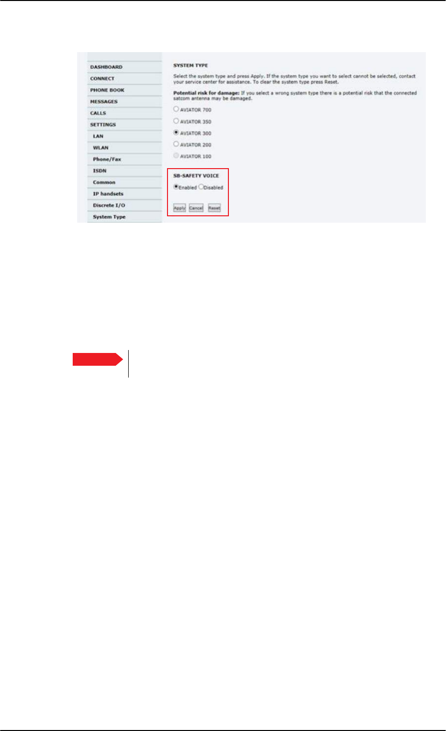
To set up the interfaces
6-56 Chapter 6: Configuration of the AVIATOR 200/300/350 system 98-127093-H
4. Click the menu SETTINGS, System Type.
Figure 6-41: Web interface, SETTINGS, System Type, software version 4.00
5. At SB-SAFETY VOICE, select Enabled.
6. Click Apply.
When SB-Safety Voice is enabled, make sure that the following settings are as follows:
• Multi-Voice is disabled
• WLAN is disabled
• Discrete output TP27 set to Active high
7. Restart the SBU.
Important Do not enable Multi-Voice and WLAN in the web interface. Multi-Voice
and WLAN are not allowed together with SB-Safety Voice.
SB-Lite.book Page 56 Tuesday, September 5, 2017 1:38 PM
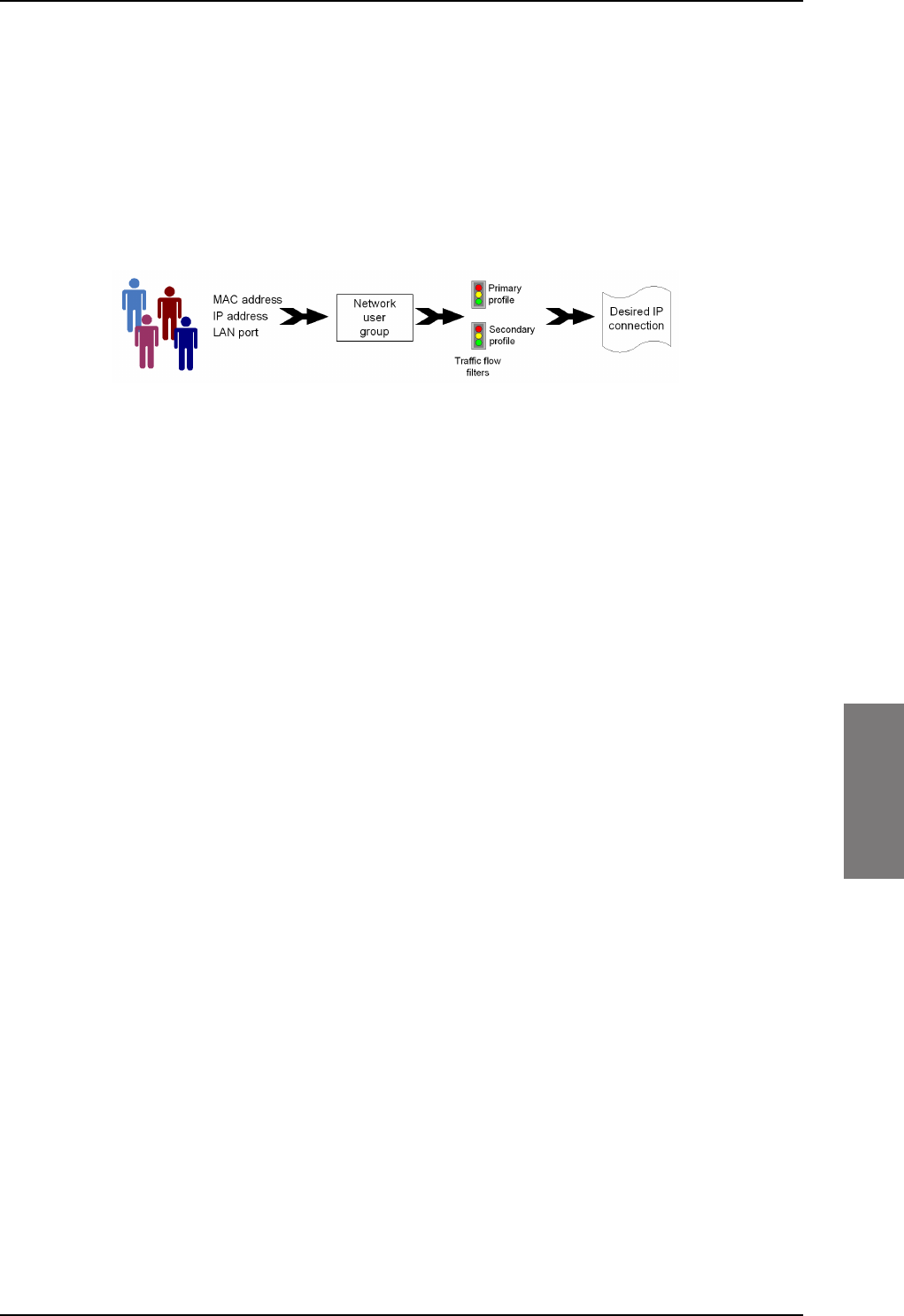
LAN/WLAN network users
98-127093-H Chapter 6: Configuration of the AVIATOR 200/300/350 system 6-57
6666
6.6 LAN/WLAN network users
6.6.1 Introduction
With the built-in router functionality the system offers a flexible use of the data channel of
the BGAN service. You can configure the use of the data channel by defining network user
groups and profiles. The following picture gives an overview of the parameters involved.
Figure 6-42: Overview over network user groups and traffic flow filters
The network user group you belong to is determined by one or more of the following:
• the IP address of the device you are using
• the MAC address of the device you are using
• the LAN port you connect to
A connected IP device will automatically be assigned to the default network user group, if it
is not specified otherwise.
For specific purposes like video streaming, a server on the network, a fixed IP address on the
connected device or changing the startup mode of a connection, you must set up network
groups with specific primary and/or secondary profiles. How to do this is described in the
following sections.
Network user groups
The network management system divides the users of the SBU into network user groups.
Each network user group has a profile which determines how the users connect to the
Inmarsat BGAN network. The network user groups can allow or restrict certain services for
different users.
For example, you may want to define:
• one network user group allowing both Standard and Streaming connections,
• one network user group for Internet, e-mail and VPN, allowing Standard connections,
• one network user group for Remote management of systems. This would be a direct
Standard connection (Bridge mode).
You can have up to 11 network user groups and global IP addresses.
Necessary steps when managing network users
The steps necessary for managing network users include:
1. Defining a network user group. See Set up the network user groups on page 6-59.
The network user groups determine settings such as:
•QoS (Standard/Streaming),
SB-Lite.book Page 57 Tuesday, September 5, 2017 1:38 PM

LAN/WLAN network users
6-58 Chapter 6: Configuration of the AVIATOR 200/300/350 system 98-127093-H
• IP addressing (Static or Dynamic, this is decided by the SIM card setup and the
service provider)
• Internet access mode (Router Mode, Bridge Mode or No Internet Access)
2. Identifying a network device. See Manage network devices on page 6-62. The
network devices are identified by their IP address, MAC address and (optionally) device
name.
3. Associating the network user group and the network device. See The network
classification table on page 6-63. The network classification table determines which
devices should belong to which network user group. When a network device is
connected, the SBU runs through the network classification table to check if the new
connection matches any of the entries in the table. When a match is found, the SBU
establishes a packet data connection (PDP context) with the settings determined for
the belonging network user group, and the device is ready for use with the SBU.
Access to the network management settings
Access to the network management settings requires an administrator password. The
default user name is admin and the default password is 1234.
The administrator can create and manage network user groups and set up a network
classification table defining priorities for devices, network user groups and LAN ports.
Important All user connections to the LAN interface may be
affected when you change the settings below,
including your own current connection.
SB-Lite.book Page 58 Tuesday, September 5, 2017 1:38 PM
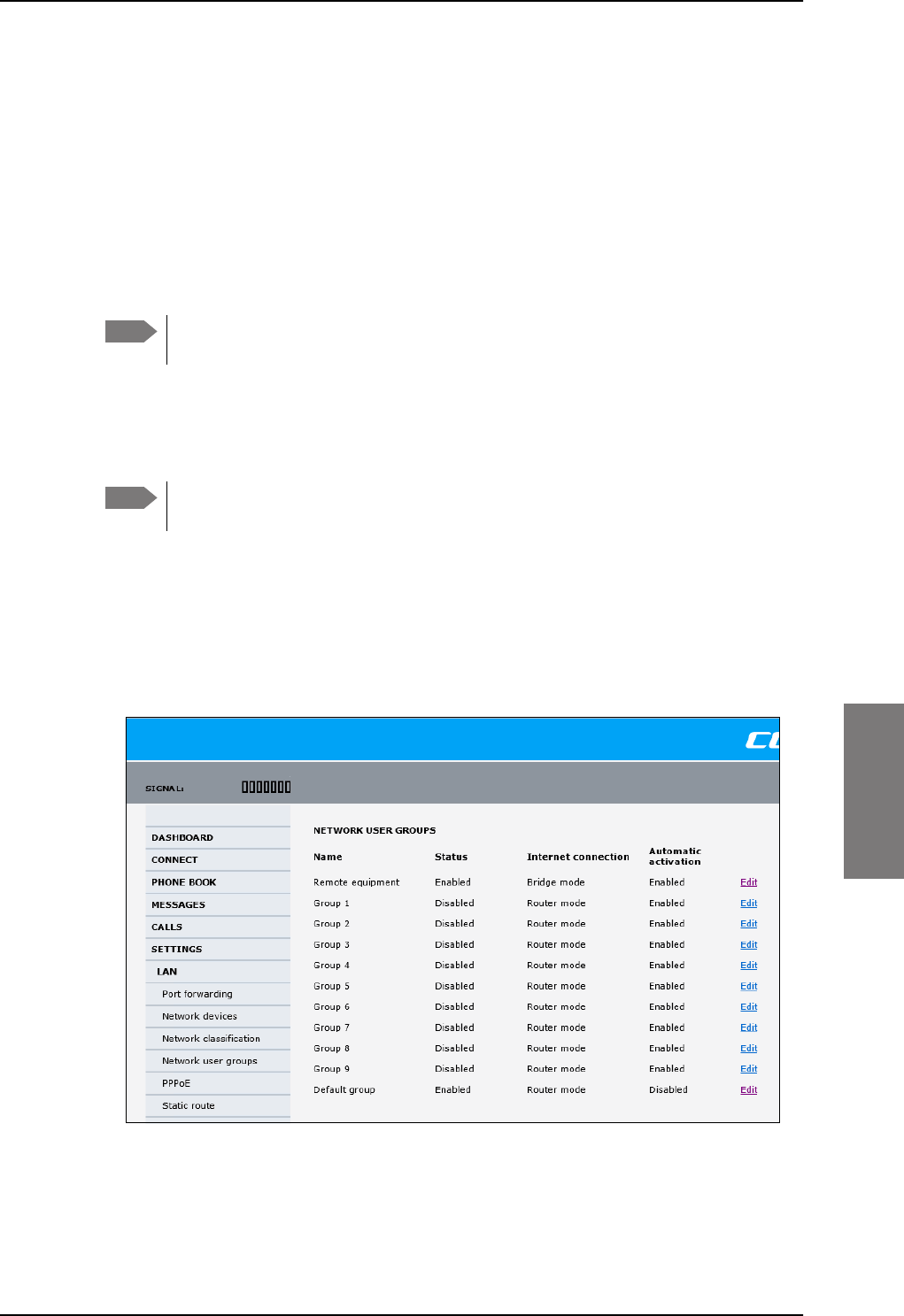
LAN/WLAN network users
98-127093-H Chapter 6: Configuration of the AVIATOR 200/300/350 system 6-59
6666
6.6.2 Set up the network user groups
Overview
A network user group, in this context, is a group of network users sharing the same Quality
of Service profile and network parameters.
There are 11 configurable network user groups. For the Default network user group, certain
settings are locked, to make sure there is always one functional network user group
available. For example, the Default network user group does not allow you to select a Bridge
mode connection.
You cannot delete network user groups. If you do not want to use them, click Edit
and select Disabled at Status in the NETWORK USER GROUP field.
Edit a network user group
The default setting of this network user group is a standard IP data connection with
automatic IP address allocation and automatic activation of the connection.
For further explanation of the terms used below, see Definitions for network
terms on page 6-65.
To edit a network user group, do as follows:
1. Select SETTINGS > LAN > Network user groups.
If prompted, enter the administrator user name and password. The default user name is
admin and the default password is 1234.
The following screen shows the 11 user groups available and their current status,
Internet connection type, and whether automatic activation is enabled or disabled.
2. Click Edit next to the network user group you want to set up.
Note
Note
Figure 6-43: Web interface: Settings, LAN, Network user groups
SB-Lite.book Page 59 Tuesday, September 5, 2017 1:38 PM
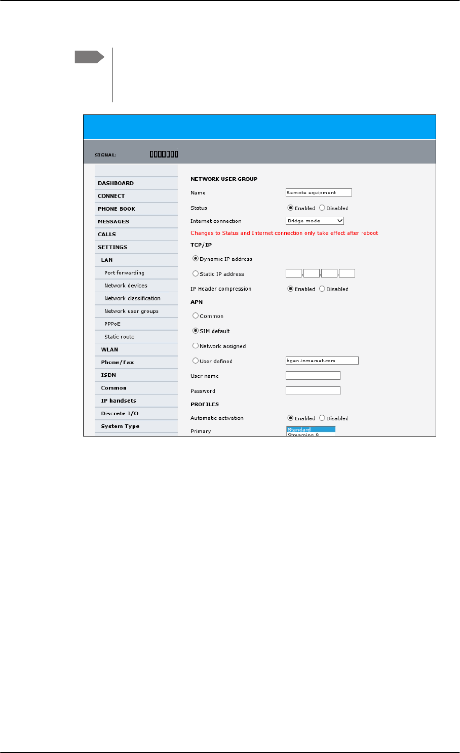
LAN/WLAN network users
6-60 Chapter 6: Configuration of the AVIATOR 200/300/350 system 98-127093-H
3. Type in a name for the group.
4. Select Enabled or Disabled.
5. Select the type of Internet connection.
•Router mode means the connection will be shared with other users, and the NAT
module of the SBU will make the necessary address translations. Read more about
NAT in NAT (Network Address Translation) on page 6-66. Use this mode if one or
more computers are connected using the LAN interface, and the SBU should acts a
router.
•Bridge mode is an exclusive connection, it is not shared with other users and NAT is
disabled. Use the Bridge mode together with a network classification entry that
selects a single computer (see The network classification table on page 6-63). The
SBU acts a a bridge for this network user group.
This mode is not available in the Default network user group.
•No internet access means no connection to the Internet is allowed. Use this
setting e.g. for IP handsets, where an Internet connection is not required. The
external voice connection is still available; this setting only affects communication
over the Internet.
Note Changes to the status and internet connection only take effect after reboot of
the SBU. This is also valid if a user wants to change the network user group,
then the SBU must be restarted before the user has access to the new network
user group.
Figure 6-44: Web interface: Settings, LAN, Network user groups, Edit
SB-Lite.book Page 60 Tuesday, September 5, 2017 1:38 PM

LAN/WLAN network users
98-127093-H Chapter 6: Configuration of the AVIATOR 200/300/350 system 6-61
6666
6. Select Dynamic IP address.
This is the IP address used externally on the satellite network.
If you want to use a static IP address, and your subscription allows it, you must still
leave this setting at Dynamic. Then select SIM default in step 8 and type in the APN
user name and password from your provider in step 9.
Your SBU will then use the static IP address set up for your SIM card.
7. Set IP Header compression to Enabled or Disabled.
For information on IP Header compression, see Header compression on page 6-65.
8. Select the source of the APN (Access Point Name).
You have the following options:
•Common. The APN is taken from the Common APN defined under SETTINGS >
Common. Refer to Set the common interface settings on page 6-27.
•SIM default. The APN is taken from the SIM card. If you want to use a static IP
address on the external network, select this option either here or in the Common
setting.
•Network assigned. The APN is assigned from the network.
•User defined. This is the preferred option. Type in the APN. APNs are provided
from the Airtime Provider. Use this option if there is no automatic provisioning for a
static IP address from the service provider.
9. If your APN uses a password, type in the user name and password provided from the
Airtime Provider.
10. At Automatic activation select whether the profile selected in the next step should
be activated automatically or manually.
•Disabled means you can activate/deactivate the profile from the Dashboard.
•Enabled means the profile is activated automatically.
11. Select the Primary profile.
Select a profile from the Primary scroll list. This profile is used by this network user
group as a first choice, when possible.
There are several predefined profiles: Standard, Streaming 8, Streaming 16, Streaming
32, Streaming 64 and Streaming 128. Additionally, you can define your own custom
profiles or any newer ones, Inmarsat defines.
Note Typing in a static IP address is currently not supported by the SwiftBroadband
network.
Note If you are going to use the static IP address from your SIM card, the user name
and password are mandatory! See the documentation for the airtime
subscription from the service provider. See step 6 above.
Note If the selected primary profile is a Streaming profile, this setting has no effect.
Streaming profiles must always be activated manually from the Dashboard.
Important If you have selected and started a Streaming connection as your primary
profile, the LAN interface will be running a Streaming connection until you
stop it or disconnect the interface.
SB-Lite.book Page 61 Tuesday, September 5, 2017 1:38 PM
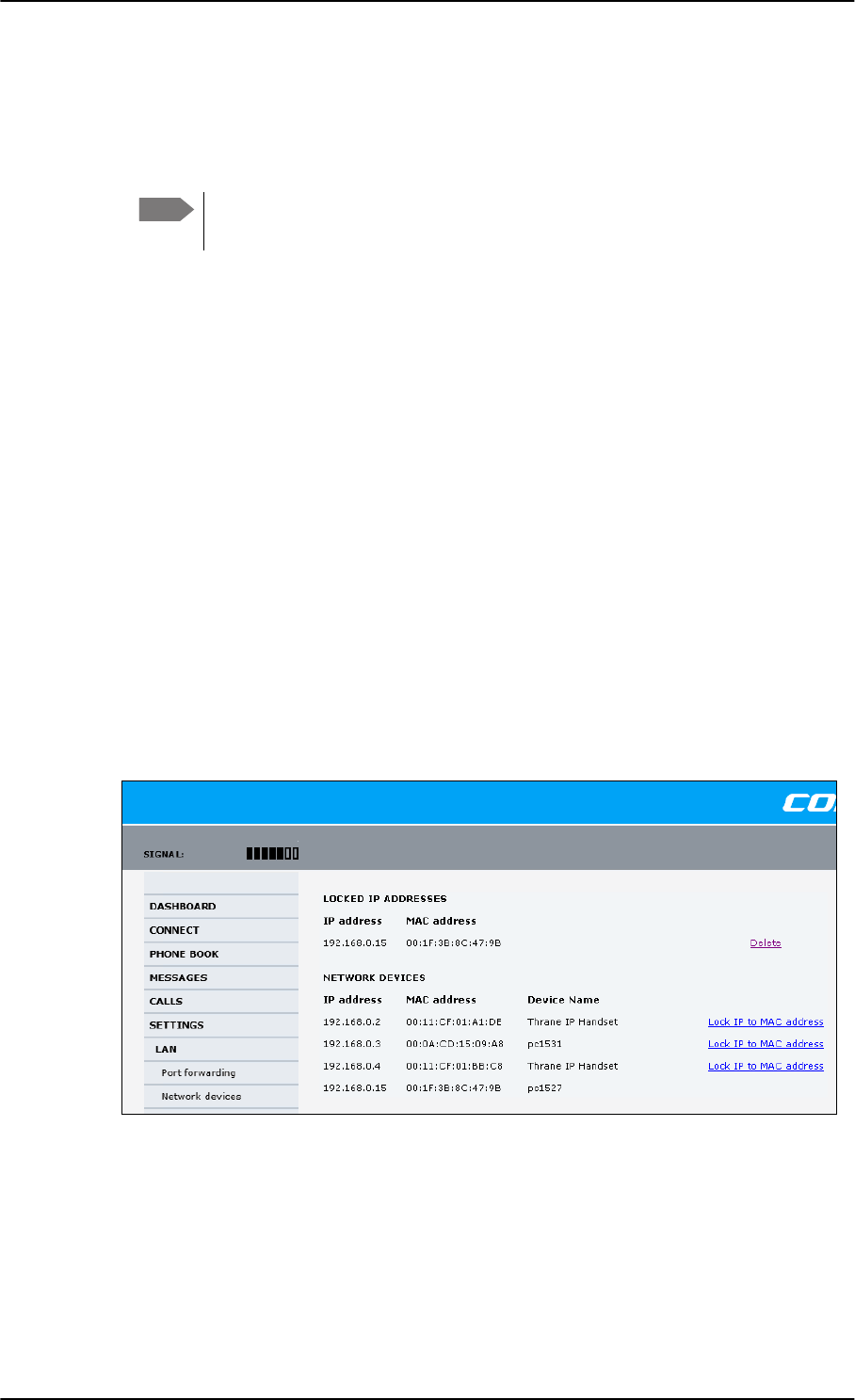
LAN/WLAN network users
6-62 Chapter 6: Configuration of the AVIATOR 200/300/350 system 98-127093-H
For further information on profiles and traffic flow filters, see To use profiles on
page 6-78 and To use traffic flow filters on page 6-82.
12. Select the Secondary profile.
To select more than one secondary profile, press and hold Ctrl or Shift while selecting.
The Context Identifiers (CIDs) for the selected primary and secondary profiles are listed
under Profile CIDs.
13. Click Apply.
Note that changes to the status and the Internet connection type of a network user group
first take effect after rebooting the AVIATOR 200/300/350 SBU.
6.6.3 Manage network devices
Overview
A network device, in this context, is an Ethernet hardware device, identified by its unique
MAC address.
When a network device with dynamic IP address is connected to the SBU, it is
automatically listed in the Network devices list.
View the list of network devices
To view the list of network devices, select SETTINGS > LAN > Network devices. All
network devices that have been connected to the SBU are listed here.
Figure 6-45: Web interface: Settings, LAN, Network devices
Note If you have selected both a primary and one or more secondary profiles you
must define a traffic flow filter before you can establish a valid connection.
SB-Lite.book Page 62 Tuesday, September 5, 2017 1:38 PM

LAN/WLAN network users
98-127093-H Chapter 6: Configuration of the AVIATOR 200/300/350 system 6-63
6666
Lock an IP address to a MAC address
When the device is locked to an IP address, the SBU will always assign this IP address to the
device with this MAC address (if DHCP is enabled and the Internet connection is in Router
mode, and not a Bridge mode connection).
To lock an IP address to a MAC address, do as follows:
1. If prompted, log in as an administrator. The default user name and password are admin
and 1234.
2. To lock a device to its current IP address, click the link next to the device. The device is
then locked to the current IP address and added to the list of locked IP addresses at the
top of the page.
3. To unlock a device from the IP address, click Delete next to the device in the LOCKED
IP ADDRESSES list.
6.6.4 The network classification table
Overview
The network classification table is used to define which network devices, IP addresses
and/or LAN ports are associated with which network user groups.
Each entry in the table shows MAC address, IP address, LAN port and network user group.
When a network device is connected, the SBU runs through the network classification table
to check if the new connection matches MAC address, IP address and LAN port in any of
the entries in the table. When a match is found, the SBU establishes a PDP context with the
settings of the network user group assigned in the matching entry. The device is now ready
for use with the SBU.
Add or edit an entry in the network classification table
The network classification table shows which devices are associated with which LAN ports
and network user groups. An Asterisk (*) is a “wild card”, meaning that any value is accepted.
You can add, edit and delete entries in the network classification table.
To add a new entry to the table or to edit an existing entry, do as follows:
1. If prompted, log in as an administrator. The default user name and password are admin
and 1234.
SB-Lite.book Page 63 Tuesday, September 5, 2017 1:38 PM
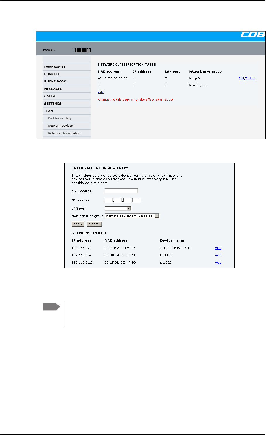
LAN/WLAN network users
6-64 Chapter 6: Configuration of the AVIATOR 200/300/350 system 98-127093-H
2. Select SETTINGS > LAN > Network classification.
Figure 6-46: Web interface: Settings, LAN, Network classification table
3. Click Edit next to the entry you want to edit, or click Add at the bottom of the list.
Figure 6-47: Web interface: Settings, LAN, Network classification table, Edit or Add
4. Click Add next to a network device you want to use, or type in the MAC address
manually at the top of the page.
If you leave a field empty, it is the same as a “wild card” and it will be shown as
an Asterisk in the Network classification table. Unless you are using a Static IP
address, the IP address field should always be left empty.
5. Select the LAN port and Network user group you want to associate with the device.
Network user groups are created and defined in the Network user group page. See Set
up the network user groups on page 6-59.
6. Click Apply.
Note
SB-Lite.book Page 64 Tuesday, September 5, 2017 1:38 PM
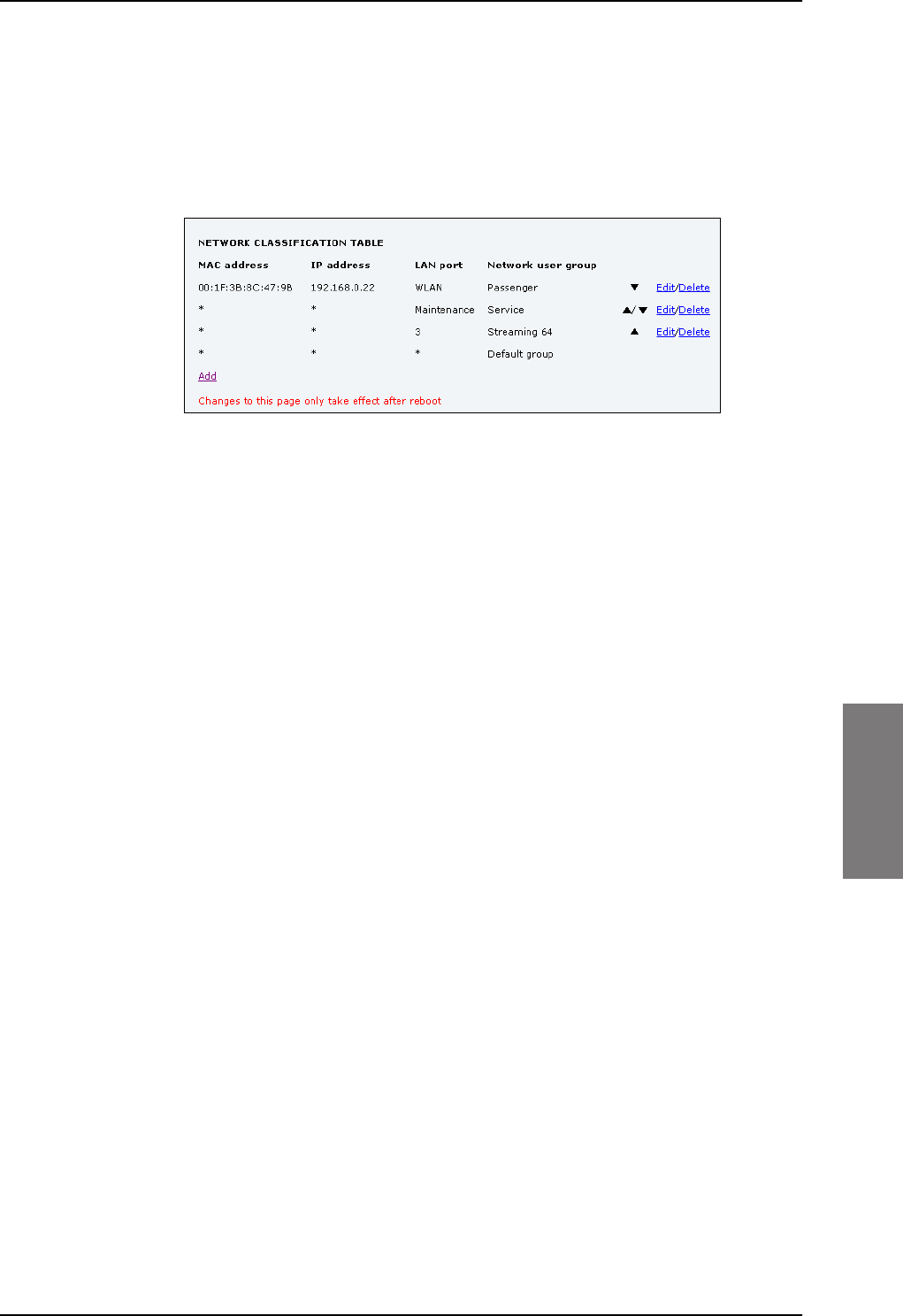
LAN/WLAN network users
98-127093-H Chapter 6: Configuration of the AVIATOR 200/300/350 system 6-65
6666
Change the priority in the network classification table
Connections are evaluated in the order they are listed. The first entry (and only the first
entry) that matches the properties of the connected device is applied, meaning that the
connection will be using the settings of the network user group assigned to that entry.
To change the priority of an entry, click the up or down arrow next to the entry.
Figure 6-48: Web interface: Settings, LAN, Network classification table, change priority
The Default network user group is always last, so it is only used if none of the other entries
match the properties of the connected device.
Remove an entry in the network classification table
In the network classification table, click Delete next to the entry you want to delete.
6.6.5 Definitions for network terms
Header compression
The header of a data packet contains control information belonging to that specific packet.
The information in the header can take up a considerable amount of bandwidth. In order to
use the bandwidth more efficiently, you can enable Header Compression, meaning the
header information is compressed, leaving some of the information out. With disabled
header compression the full header ist transmitted with each data packet. This takes up
bandwidth and means a more reliable data transmission with less data loss.
You can select whether or not to use Header Compression for your data transmission.
•Header Compression enabled: More efficient use of the bandwidth available,
recommended typically for Internet, e-mail, ftp applications etc.
•Header Compression disabled: More reliable data transmission. Recommended for
time-critical applications like VoIP and streaming applications, as well as other
applications where packet loss is to be minimized.
If there are problems with packet loss you might want to disable header compression and
see whether the header compression is the reason for the packet loss.
SB-Lite.book Page 65 Tuesday, September 5, 2017 1:38 PM
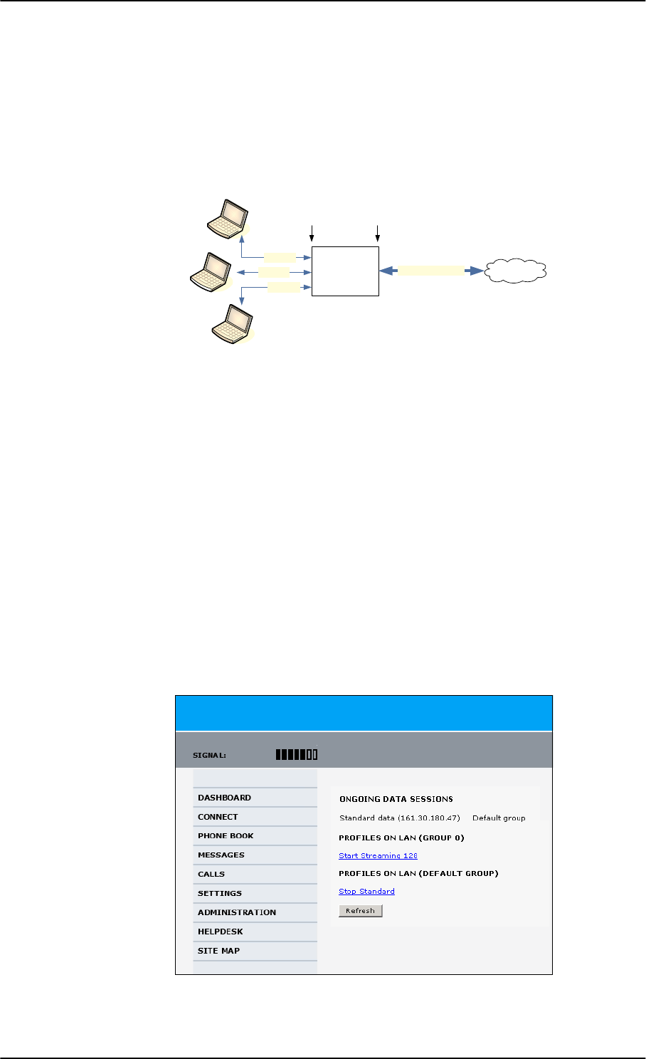
LAN/WLAN network users
6-66 Chapter 6: Configuration of the AVIATOR 200/300/350 system 98-127093-H
6.6.6 NAT (Network Address Translation)
NAT enables a local-area network to use one set of private IP addresses for internal traffic
and an assigned or static IP address for external traffic. The built-in NAT module in the SBU
makes all necessary address translations between the local-area traffic and the external
traffic.
Figure 6-49: NAT (Network Address Translation)
If more than one user is connected, you must select a network user group with Router
mode to use the NAT functionality of the SBU.
6.6.7 Start and stop any data session
The administrator can start and stop data sessions for all network user groups connected to
the SBU.
To start or stop a data session, do as follows:
1. Select CONNECT.
If prompted, enter the administrator user name and password. The default user name is
admin and the default password is 1234.
Under ONGOING DATA SESSIONS at the top you can see which data sessions are
currently active.
$
%
&
7HUPLQDO
ZLWK1$7
7UDIILF$
7UDIILF&
7UDIILF$%DQG&
7UDIILF%
3ULYDWH
,3DGGUHVVHV
IRU$%DQG&
$VVLJQHGRU
VWDWLF
,3DGGUHVV
,QWHUQHW
/RFDODUHD ([WHUQDO
Figure 6-50: Web interface: Connect, to start and stop data sessions (example)
SB-Lite.book Page 66 Tuesday, September 5, 2017 1:38 PM
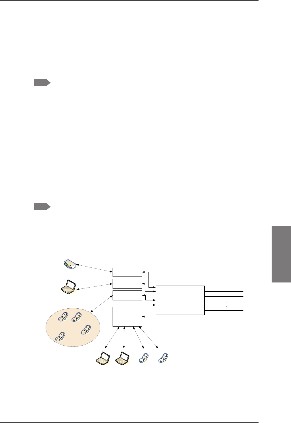
LAN/WLAN network users
98-127093-H Chapter 6: Configuration of the AVIATOR 200/300/350 system 6-67
6666
In the example above you can manually start the Streaming 128 connection of
GROUP 0 and stop the Standard connection of the DEFAULT GROUP.
2. Click on the session you want to start or stop.
3. Click Refresh to update the current state of the connection(s). Note that there might
be some latency when updating the connection status, you might have to wait and click
Refresh again to update the Dashboard to the current state.
The PDP context for the data session is not activated before any unit in the LAN
tries to communicate, e.g. sends a DHCP request.
6.6.8 Establish a PPPoE connection
Overview
You can establish a Point-to-Point-over-Ethernet (PPPoE) connection to the BGAN network
using the AVIATOR 200/300/350 system. Use this connection type if you want to control
start and stop of the connection independently from the built-in web interface of the SBU.
Possible applications for this type of connection are as follows:
• Connecting a router
• Connecting broadcast equipment, optionally through a PC
• Establishing a Pico cell for the use of cell phones
Without the built-in Router option the AVIATOR 200/300/350 system is limited to
one PPPoE connection.
The following drawing shows how the PPPoE connection and the built-in web interface
handle connections to the SwiftBroadband network.
Figure 6-51: Example for PPPoE connections
Note
Note
6%8
3'3&RQWH[WXSWR
6ZLIW%URDGEDQG
QHWZRUN
%XLOWLQ
ZHE
LQWHUIDFH
333R(
FRQQHFWLRQ
3&DQGRUEURDGFDVWHTXLSPHQW
8VHU3&
$SSOLFDWLRQV
IRU333R(
+DQGOLQJFRQQHFWLRQ
WRWKH%*$1WHUPLQDO
$VVLJQLQJFRQQHFWLRQ
3'3FRQWH[WWRJRRXW
RQWKH6ZLIW%URDGEDQG
QHWZRUN
5RXWHU
3LFRFHOO
333R(
FRQQHFWLRQ
8VHU3&
333R(
FRQQHFWLRQ
:LUH
+DQGVHW
,3
+DQGVHW
SB-Lite.book Page 67 Tuesday, September 5, 2017 1:38 PM
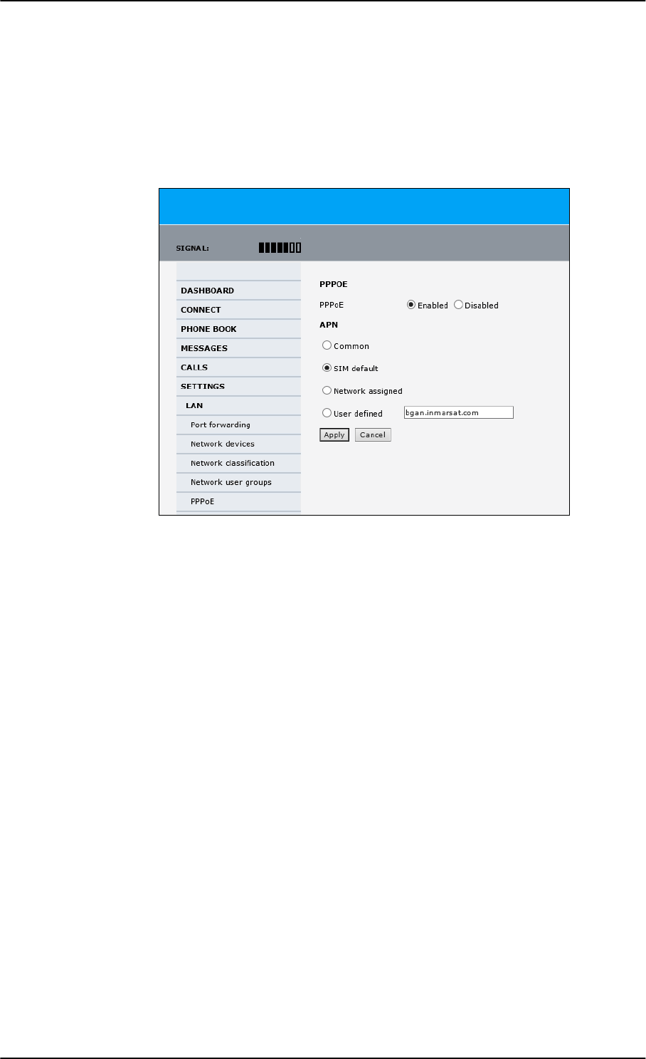
LAN/WLAN network users
6-68 Chapter 6: Configuration of the AVIATOR 200/300/350 system 98-127093-H
Enable PPPoE network connections in the AVIATOR 200/300/350 system
During the configuration of the system you can configure whether the system should allow
and handle PPPoE network connections.
To enable or disable the system to support PPPoE network connections do as follows:
1. Select SETTINGS > LAN > PPPoE
Figure 6-52: Web interface, Settings, LAN, PPPoE
2. Select Enabled or Disabled (default).
3. Check with your airtime provider what your APN is and select accordingly.
4. Click Apply to send the settings to the terminal.
How to configure the connected PC, router or other equipment
You must configure the equipment correctly to establish a network connection using
PPPoE. How to set up a new network connection depends on the type of equipment, refer
to the user documentation of the equipment.
You need the following parameters:
•User name and password
The user name and password can be left blank. Then the registration on the APN is most
commonly done in a way that the data connection will be established with a dynamic
IP address from the airtime provider.
To request a static IP (if subscribed to) from the APN you must type in the user name
and password from your airtime subscription.
Note for MAC OS: User name and password are required. Use user name void and
password void. This works for some ISPs. Contact your airtime provider for further
information.
• For setups that have a check box for Enable LCP extensions, deselect this.
SB-Lite.book Page 68 Tuesday, September 5, 2017 1:38 PM
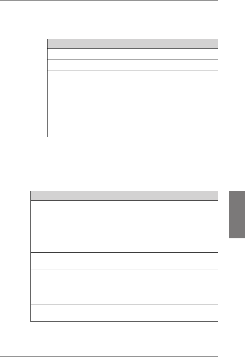
LAN/WLAN network users
98-127093-H Chapter 6: Configuration of the AVIATOR 200/300/350 system 6-69
6666
•Service name: For certain services, i.e. a streaming class, you must type in a specified
text string when asked for a service name. The following table shows the service names
and descriptions that are supported by the terminal.
PPPoE setup with a non-default APN
You can set up a network connection using PPPoE for another APN than the default APN.
Check the documentation from the Service provider for the new APN name. Enter the
following commands in the field Service name when setting up the network connection:
Table 6-9: PPPoE connection, service names and descriptions for custom APN
Service name for custom APN Description
XBBa
a. For SwiftBroadband the part of the service name “XBB” can be replaced by “SBB”.
:AT+CGDCONT=1,ip,”<APN name>”;
+CGEQREQ=1,3
Standard IP data connection
XBB:AT+CGDCONT=1,ip,”<APN name>”;
+CGEQREQ=1,1,8,8,8,8,2,0,“0E0”,”0E0”,3,0,0
Streaming IP data connection
8 kbps
XBB:AT+CGDCONT=1,ip,”<APN name>”;
+CGEQREQ=1,1,16,16,16,16,2,0,“0E0”,”0E0”,3,0,0
Streaming IP data connection
16 kbps
XBB:AT+CGDCONT=1,ip,”<APN name>”;
+CGEQREQ=1,1,32,32,32,32,2,0,“0E0”,”0E0”,3,0,0
Streaming IP data connection
32 kbps
XBB:AT+CGDCONT=1,ip,”<APN name>”;
+CGEQREQ=1,1,64,64,64,64,2,0,“0E0”,”0E0”,3,0,0
Streaming IP data connection
64 kbps
XBB:AT+CGDCONT=1,ip,”<APN name>”;
+CGEQREQ=1,1,128,128,128,128,2,0,“0E0”,”0E0”,3,0,0
streaming IP data connection
128 kbps
XBB:AT+CGDCONT=1,ip,”<APN name>”;
+CGEQREQ=1,1,512,512,512,512,2,0,“0E0”,”0E0”,3,0,0
streaming IP data connection
X-Stream
Service name Description
Blank default, primary standard IP data connection
XBBa:BACKGROUND
a. For SwiftBroadband the part of the service name “XBB” can be replaced by “SBB”.
default, primary standard IP data connection
XBB:STREAM8K primary streaming IP data connection 8 kbps
XBB:STREAM16K primary streaming IP data connection 16 kbps
XBB:STREAM32K primary streaming IP data connection 32 kbps
XBB:STREAM64K primary streaming IP data connection 64 kbps
XBB:STREAM128K primary streaming IP data connection 128 kbps
XBB:X-STREAM primary streaming IP data connection up to 512 kbps.
Table 6-8: PPPoE connection, service names and descriptions
SB-Lite.book Page 69 Tuesday, September 5, 2017 1:38 PM
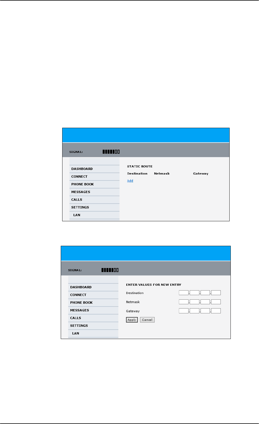
LAN/WLAN network users
6-70 Chapter 6: Configuration of the AVIATOR 200/300/350 system 98-127093-H
Example: To set up a standard background data connection using the APN
“bgan.inmarsat.com” enter:
XBB:AT+CGDCONT=1,ip,”bgan.inmarsat.com”;+CGEQREQ=1,3
For more information about the command syntax see the standard 3GPP TS 27.007.
6.6.9 To set up static routing
When you have an external gateway connected to your SBU, the SBU is not automatically
able to “see” the network on the other side of the gateway. However, you can set up your
SBU to communicate with a device on the other side of a gateway, by using Static routing.
To set up a new device for static routing, do as follows:
1. Select SETTINGS > LAN > Static route.
Figure 6-53: Web interface, Settings, LAN, Static route
2. Click Add.
Figure 6-54: Web interface, Settings, LAN, Static route, add
3. Enter the values for your device.
• Destination: The IP address you want to route to.
•Netmask: The netmask you want to route to.
• Gateway: The gateway, e.g. the address of a wireless access point or router to which
the destination device is connected.
SB-Lite.book Page 70 Tuesday, September 5, 2017 1:38 PM

Administration
98-127093-H Chapter 6: Configuration of the AVIATOR 200/300/350 system 6-71
6666
4. Click Apply.
The values for the new entry are now in the list. This means that the SBU can
communicate with the destination IP address on the other side of the gateway.
6.6.10 SNMP interface
You can connect equipment to perform SNMP queries on the SBU in order to retrieve
configuration and present settings.
Contact AVIATOR.support@cobham.com to obtain the MIB files.
6.7 Administration
In this section of the web interface you can configure a number of administrative settings:
•Access the administration settings
•Save and load a configuration
•Call charges
•Log handling
•Data limits
•To use profiles
•To use traffic flow filters
•SIM card access protection: SIM PIN and SIM Lock
•Set up user permissions
•Remote management
•Remote activation of a connection using SMS
•Link monitoring (SwiftBroadband only)
•Restricted dialing
•Multi-voice (option)
6.7.1 Protect the SBU against unintended configuration changes
You can protect the SBU against unintended changes of the setup:
1. Change the administrator password from user name: admin and password: 1234 to a
user name and password of your choice. For further details see Change the
administrator password on page 6-72.
2. You can deny non-administrator users access to certain functions and make the
respective pages in the web interface read-only. For further details see Set up user
permissions on page 6-87.
SB-Lite.book Page 71 Tuesday, September 5, 2017 1:38 PM
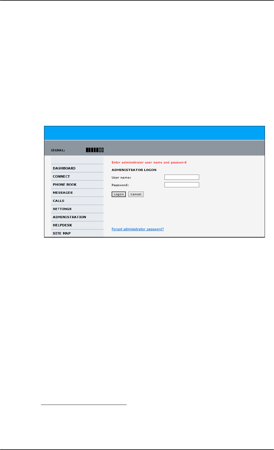
Administration
6-72 Chapter 6: Configuration of the AVIATOR 200/300/350 system 98-127093-H
6.7.2 Access the administration settings
Log on as administrator
The Administration settings require an Administration user name and password. You must
also login as an administrator in the sections for SETTINGS, LAN, Network Devices,
Network classification, Network user groups and PPPoE.
To log on as administrator, do as follows:
1. Select ADMINISTRATION from the left navigation pane.
2. Enter the Administration user name and password.
The default user name is admin and the default password is 1234.
If you have forgotten the administrator password, you can reset the password by
clicking the link at the bottom of the page.1 For further information, see the next
section Reset the administrator password.
3. Click Logon.
The Administration page is now updated to let you change the user name and
password, Save/load a configuration or log off Administration.
Change the administrator password
If you have a Level D system with the Built-in CMU/ACARS option and the ACARS service is
enabled, the admin password must fulfill the following requirements:
• have at least 8 characters
• must contain letters, figures and special characters (<>,;.:-_/*-+!.#¤%&()=?@£${[]}|)
The default password 1234 is allowed, but it will trigger a warning that is displayed after
each reboot of the system.
Figure 6-55: Web interface: Administration
1. The link is only shown when the PC is connected to the Maintenance connector on the SBU
front plate.
SB-Lite.book Page 72 Tuesday, September 5, 2017 1:38 PM
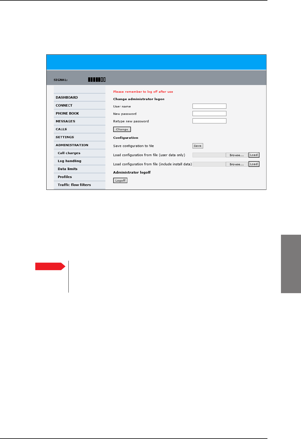
Administration
98-127093-H Chapter 6: Configuration of the AVIATOR 200/300/350 system 6-73
6666
To change the administrator password, do as follows:
1. After entering the administrator user name and password in the ADMINISTRATION
page, locate the section Change administrator logon.
Figure 6-56: Web interface: Administration, change administrator logon
2. Type in the existing user name.
3. Type in the new password and retype it on the next line.
4. Click Change. At the next logon the new password is required.
Reset the administrator password
If you have forgotten and need to reset the administrator password, do as follows:
1. Contact your supplier for a reset code.
Report the serial number and IMEI number of the terminal.
You find the serial number and IMEI number in the Dashboard.
Important To reset the administrator password you must connect the PC to the
Maintenance connector on the SBU front plate. If not, the link Forgot
administrator password? on the ADMINISTRATOR LOGON page will not
be visible.
SB-Lite.book Page 73 Tuesday, September 5, 2017 1:38 PM
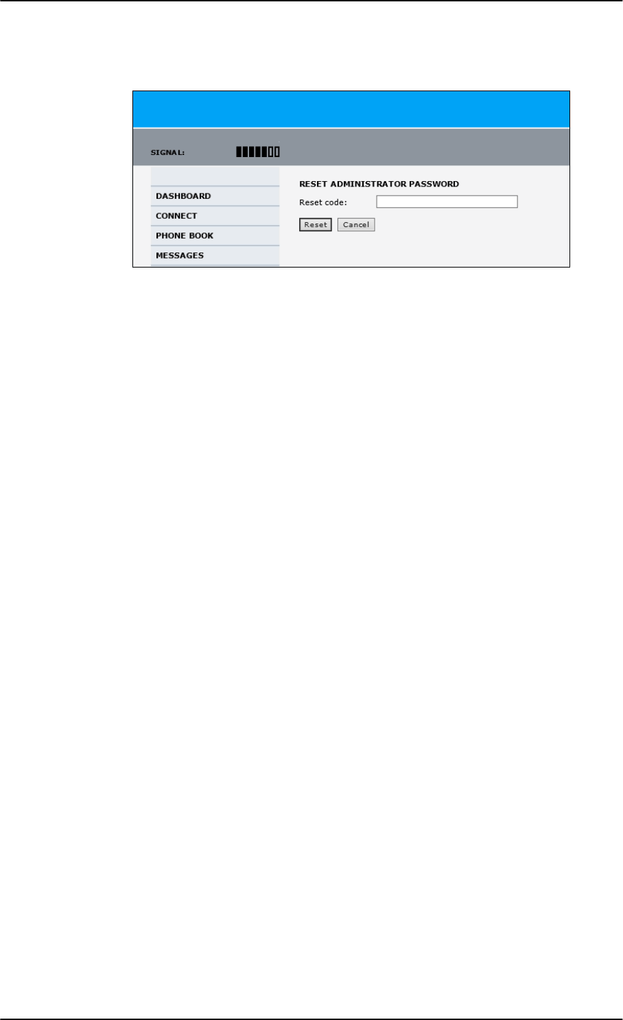
Administration
6-74 Chapter 6: Configuration of the AVIATOR 200/300/350 system 98-127093-H
2. Click the link Forgot administrator password? at the bottom of the
ADMINISTRATOR LOGON page (see the previous section).
Figure 6-57: Web interface: Administration, Reset administrator password
3. Type in the reset code obtained from your supplier and click Reset.
4. Type in the user name Admin and the default password 1234.
5. Click Logon.
For information on how to change the password, see the next section Change the
administrator password.
Log off administration
If you have not entered anything for 30 minutes under ADMINISTRATION, you are logged
off automatically. To log off manually, click Logoff under administrator logoff in the
ADMINISTRATION page.
SB-Lite.book Page 74 Tuesday, September 5, 2017 1:38 PM
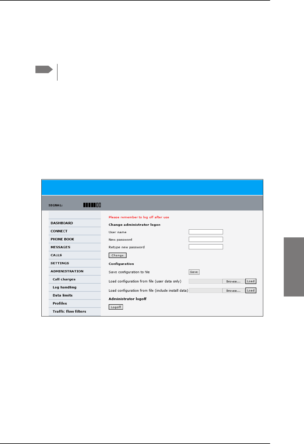
Administration
98-127093-H Chapter 6: Configuration of the AVIATOR 200/300/350 system 6-75
6666
6.7.3 Save and load a configuration
If you need to reuse a configuration in another SBU, you can save the current configuration
to a file, which can then be loaded into the other SBU. You can also use this feature for
backup purposes.
Configuration files can only be exchanged between SBUs with the same
software version!
Save a configuration to a file
The settings from the following pages of the web interface are saved in the configuration
file:
• SETTINGS
• ADMINISTRATION
• PHONE BOOK
To save your current configuration to a file, do as follows:
1. In the ADMINISTRATION page, under Configuration, click Save.
Figure 6-58: Web interface: Administration, saving a configuration file
2. Accept the default destination file name or type in the destination file name and
location.
3. Click OK. The configuration is now saved to a file. This file is used to load the
configuration into another SBU.
Note
SB-Lite.book Page 75 Tuesday, September 5, 2017 1:38 PM
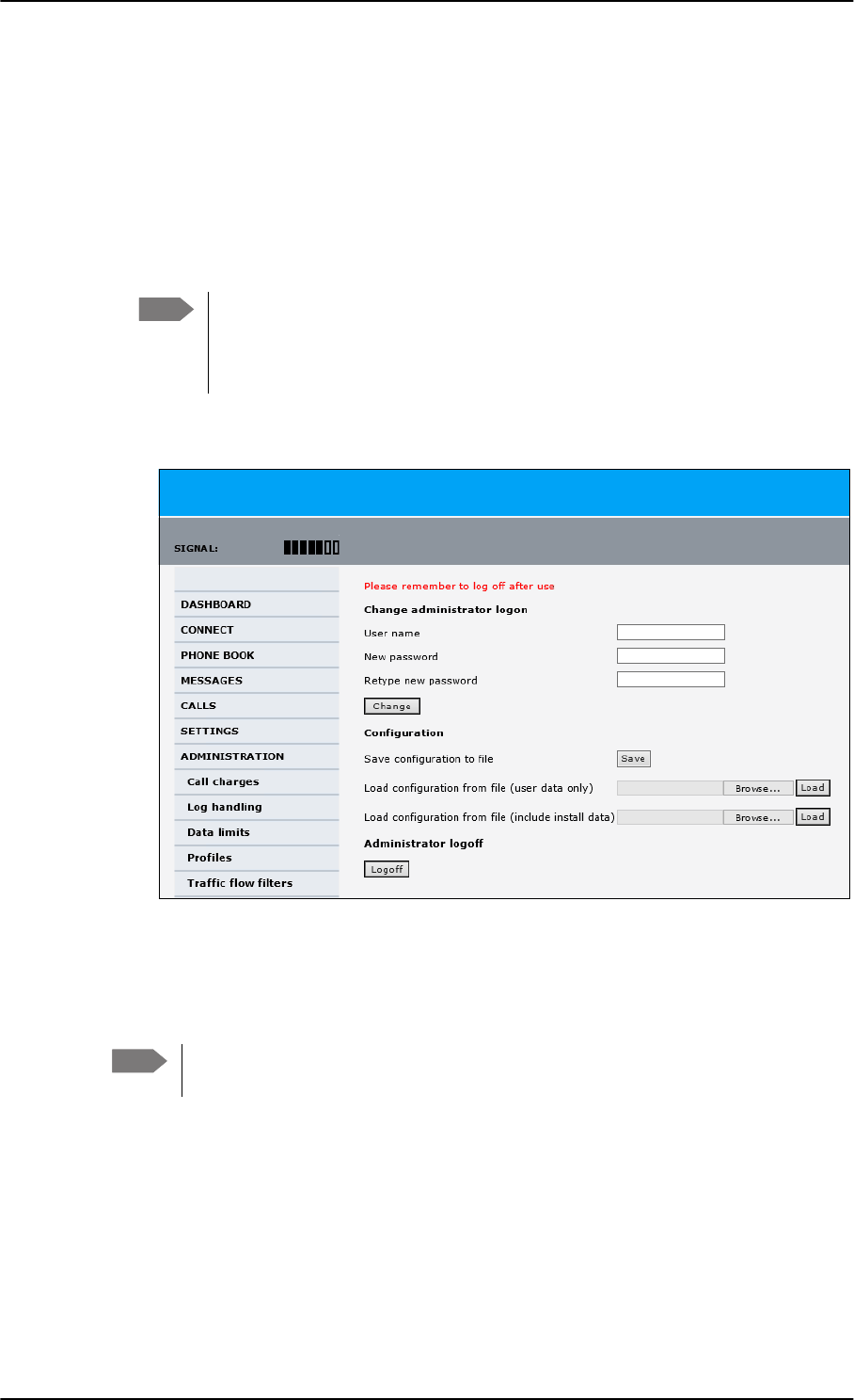
Administration
6-76 Chapter 6: Configuration of the AVIATOR 200/300/350 system 98-127093-H
Load a configuration from a file
In this example the PC is connected to the SBU front maintenance connector. To load a
configuration from a file, do as follows:
1. In the ADMINISTRATION page, under Configuration, select the upload type:
•Load configuration from file (include install data), available when connected
to the SBU front maintenance connector.
The install data are the pages Discrete I/O, RF settings and External systems.
•Load configuration from file (user data only). This upload type is available on
any other LAN/WLAN interface of the SBU.
2. Click Browse... to browse to the file you want to import. Then click Open.
3. Click Load.
The new configuration is now loaded into your SBU.
4. Restart the SBU to activate the new configuration.
Note This feature can only be used with systems of the same system type, for
example one AVIATOR 200 SBU to another AVIATOR 200 SBU. To use this
upload type the PC must be connected to the SBU front maintenance
connector.
Figure 6-59: Web interface: Administration, saving a configuration file
Note Configuration files can only be exchanged between SBUs with the same
software version!
SB-Lite.book Page 76 Tuesday, September 5, 2017 1:38 PM
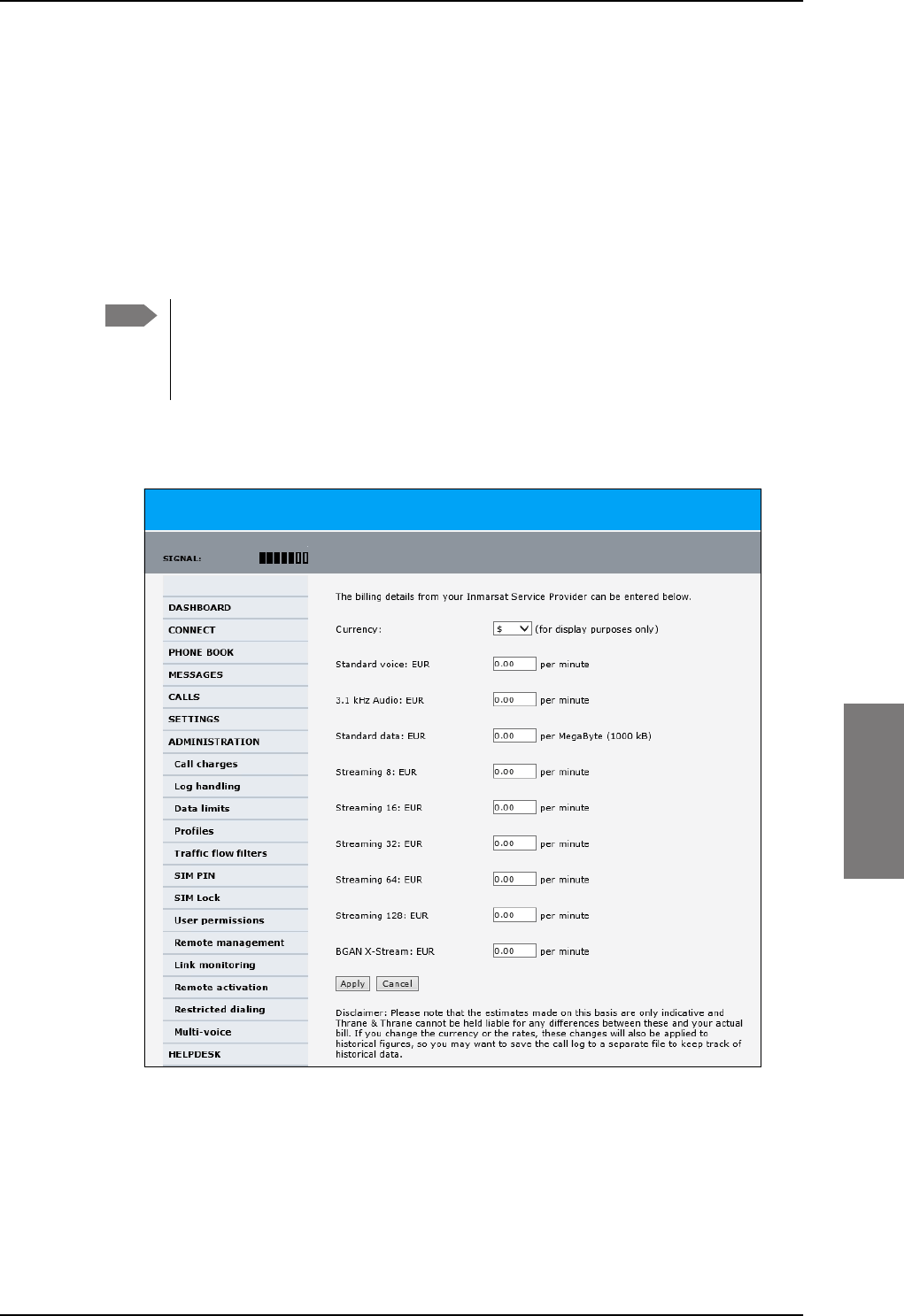
Administration
98-127093-H Chapter 6: Configuration of the AVIATOR 200/300/350 system 6-77
6666
6.7.4 Call charges
In this section you can enter the call charges so you at all times can see the current charges
for the services used. Consult the documentation from your service provider for the
subscribed services, then enter these tariffs in the web interface. The system automatically
calculates the charges for your calls and data sessions. The entered tariffs are used for
estimating the charges for calls and data sessions. The estimated charge is listed for each
call or data session in the call log. For further information, see the AVIATOR 200/300/350
user manual.
To enter the call tariffs, do as follows:
1. From the left navigation pane, select ADMINISTRATION > Call Charges.
Figure 6-60: Web interface: Administration, Call Charges
2. Select the currency from the Currency drop-down list.
3. Enter the tariff for each of the services.
4. Click Apply.
Note Thrane & Thrane does not take responsibility for the correctness of the estimated
charges. This calculation is only a rough estimate of the charge, based on the tariff
entered by the user. Also, the Airtime Provider may have different methods of
calculating the charge.
SB-Lite.book Page 77 Tuesday, September 5, 2017 1:38 PM
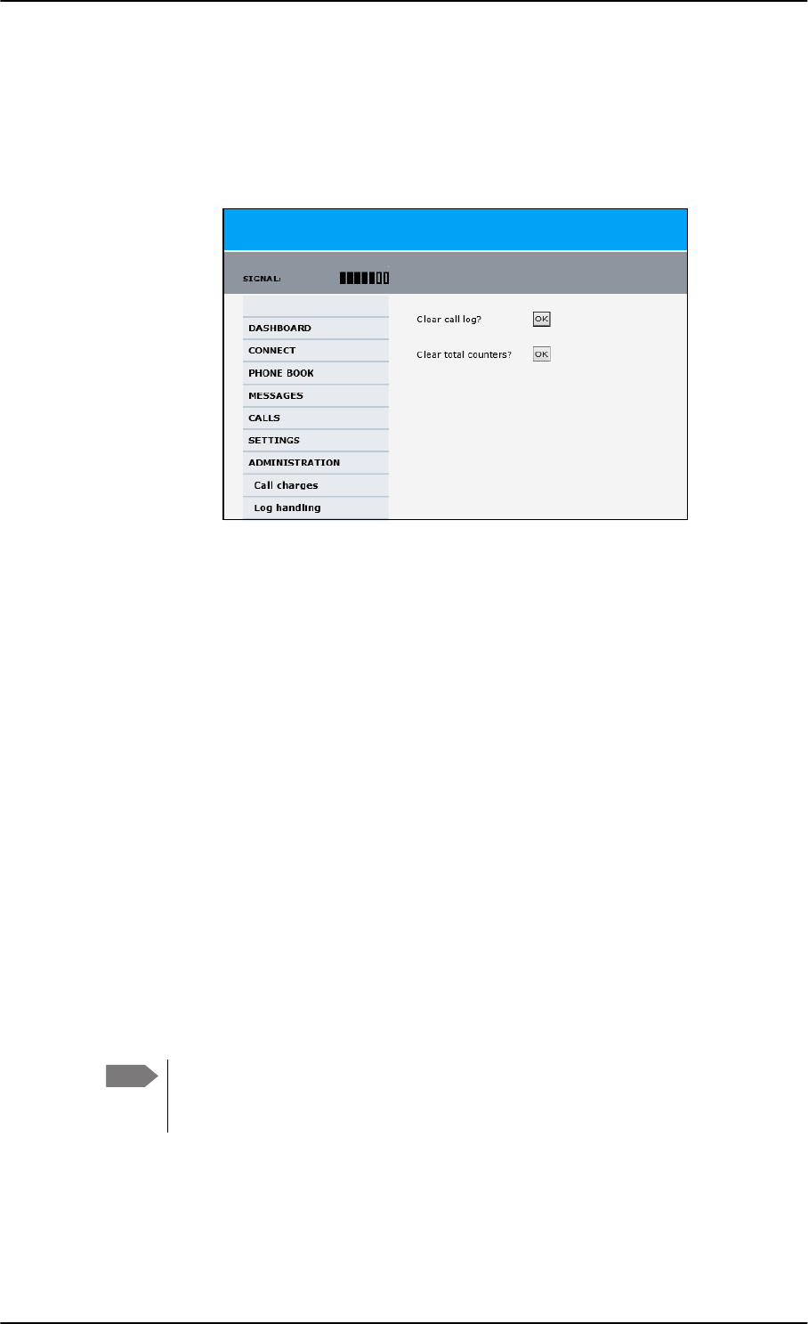
Administration
6-78 Chapter 6: Configuration of the AVIATOR 200/300/350 system 98-127093-H
6.7.5 Log handling
To clear the logs of the SBU and/or reset the counters for the time connected, do as
follows:
1. From the left navigation pane in the ADMINISTRATION page, select Log Handling.
Figure 6-61: Web interface: Administration, Log Handling
2. To clear the Call log, click OK next to Clear call log?.
3. To clear the total counters, click OK next to Clear total counters?.
This will reset the Time connected counters on the Calls page.
6.7.6 Data limits
You can set a limit for the use of data services that can be downloaded over the
AVIATOR 200/300/350 system. You either specify a maximum number of MB for the
standard data connection, and/or a time interval from start to end for a streaming
connection.
For a detailed description how to access the SBU from a remote location see the
AVIATOR 200/300/350 user manual.
6.7.7 To use profiles
The profiles are used in the network user groups. You select one or several profiles when
setting up a network user group. You need an administrator password to define profiles and
traffic flow filters.
Together with traffic flow filters the profiles are used as a tool to manage the traffic flow.
If you have selected more than one profile (one primary and one or more
secondary profiles) for an interface, you must define traffic flow filter(s) before
you can establish a valid connection.
Note
SB-Lite.book Page 78 Tuesday, September 5, 2017 1:38 PM
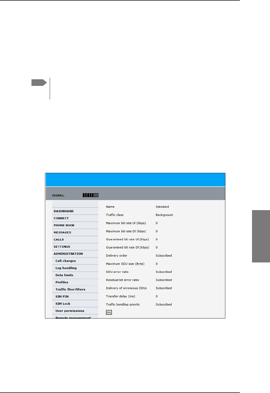
Administration
98-127093-H Chapter 6: Configuration of the AVIATOR 200/300/350 system 6-79
6666
What is a profile?
A profile is a collection of Quality of Service (QoS) settings and other settings defining the
mode in which data is transmitted on an interface. For example, a profile is used to define
whether the connection is a Streaming connection or a Standard connection.
You can select between a number of predefined profiles or define your own profiles for
your data transmission. For further information on profiles, refer to the 3GPP standard TS
23.107 “Quality of Service (QoS) concept and architecture”.
If no traffic flow filters are defined, the Primary profile for a network user group is
used for all traffic from that network user group. Then the secondary profile will
not become active.
To learn more about traffic flow filters see What are traffic flow filters? in the next section.
Select the profiles for a network user group
When you set up a network user group, you typically select one of the predefined profiles
to use as a Primary profile for that network user group. You select optionally one or more
Secondary profiles.
For further information on how to select the profiles, see LAN/WLAN network users on
page 6-57.
You typically do not need to define new profiles, the predefined profiles cover the most
common applications. You can customize a user profile and set up several user-defined
profiles.
Note
Figure 6-62: Web interface, Administration, Profiles, Example: Standard
SB-Lite.book Page 79 Tuesday, September 5, 2017 1:38 PM
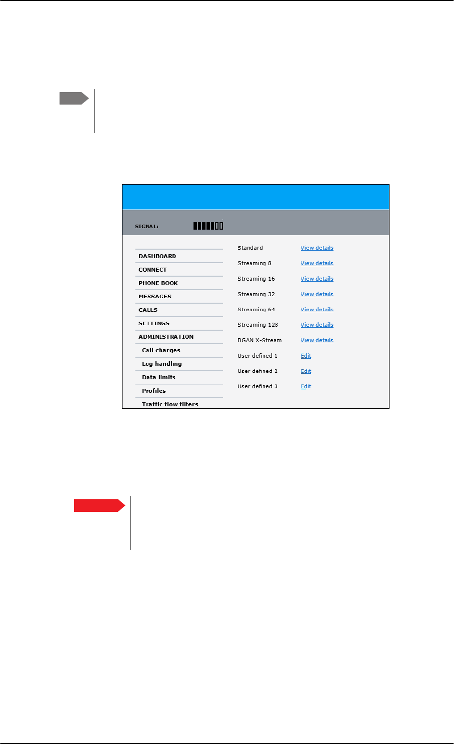
Administration
6-80 Chapter 6: Configuration of the AVIATOR 200/300/350 system 98-127093-H
Define new profiles
When you define your profiles you can select Subscribed for many of the settings. If you
select Subscribed, the value given in your Airtime subscription is automatically used.
For AVIATOR 200/300/350, the maximum Streaming bit rate is 128 kbps.
AVIATOR 350 with an HGA can also handle the X-Stream service (up to
approximately 450 kbps).
To define a new profile, do as follows:
1. From the left navigation pane, select ADMINISTRATION > Profiles.
Figure 6-63: Web interface. Administration, Profiles, select profile (Example AVIATOR 350)
2. Click Edit for the profile you want to define.
3. Fill in the top field with the name for your profile.
4. In the Traffic class row of your new profile, select a class from the drop-down list.
You may select one of the following:
•Conversational is real-time two-way conversation. It is primarily used for voice
over IP and video conferences.
•Streaming is real-time one-way communication. It is primarily used for video and
audio.
•Interactive is two-way communication (not real-time). It is used for
communication that is not very delay-sensitive, such as web browsing, data base
retrieval and server access. Examples of machines interaction with remote
equipment are: polling for measurement records and automatic data base enquiries
(tele-machines).
Note
Important For best performance, choose the right traffic class for your application. In
general, Standard IP (Background) is best suited for TCP/IP applications,
e.g. web browsing, e-mail, file transfer, VPN. Streaming IP is best suited for
UDP traffic, e.g. live video or audio.
SB-Lite.book Page 80 Tuesday, September 5, 2017 1:38 PM

Administration
98-127093-H Chapter 6: Configuration of the AVIATOR 200/300/350 system 6-81
6666
•Background is used for data which is not delay-sensitive, such as E-mail, SMS,
download of databases and reception of measurement records.
5. Type in the bit rates in kbps in the following rows:
•Maximum bit rate Ul (kbps) is the maximum upload bit rate allowed for this
profile.
•Maximum bit rate Dl (kbps) is the maximum download bit rate allowed for this
profile.
•Guaranteed bit rate Ul (kbps) is the guaranteed upload bit rate needed for this
profile.
•Guaranteed bit rate Dl (kbps) is the guaranteed download bit rate needed for this
profile.
6. In the Delivery order row, select from the scroll list whether or not data should be
delivered in the same order it was sent.
•Yes means the data packets are delivered in the same order they were sent.
7. In the Maximum SDU size (byte) row, type in the maximum allowed packet size in
Bytes (rounded off to nearest 10). The maximum packet size possible is 1520.
8. In the Delivery of erroneous SDUs row, select one of the following from the list:
•Yes means packets are allowed to contain errors. This setting is suitable for delay-
sensitive transmission, because the need for retransmission is limited. The SDU Error
settings in step 9 and step 10 will apply.
•No means packets are not allowed to contain errors, and the SDU Error setting in
step 9 will not be applied. This setting is suitable where error-free transmission is
important and delays are accepted.
•No detect means that errors will not be detected, and the SDU Error setting in step
9 will not be applied.
9. If you selected Yes in step 8, select from the SDU error ratio drop-down list the
fraction of a packet allowed to be lost or erroneous.
10. Select from the Residual bit error ratio drop-down list the undetected bit error ratio
of a packet. If no error detection is requested, Residual bit error ratio indicates the bit
error ratio in the delivered packets.
11. In the Transfer delay (ms) row, type in the delay in ms. This is the delay from the time
data is received in the SBU until it arrives at the receiving end.
• If the Transfer delay is 500 ms, error correction is disabled.
• If the Transfer delay is 4000 ms, error correction is applied.
12. In the Traffic handling priority row, select from the drop-down list which priority
this connection should have.
13. Click Apply.
The new profile is now added, and can be selected from the lists of primary and
secondary profiles when you set up your interfaces.
Note When you click Apply, the bit rate values you typed in may be rounded off
because only certain values are allowed.
SB-Lite.book Page 81 Tuesday, September 5, 2017 1:38 PM
Administration
6-82 Chapter 6: Configuration of the AVIATOR 200/300/350 system 98-127093-H
6.7.8 To use traffic flow filters
Purpose of the traffic flow filters
The purpose of the traffic flow filters is to assign different priorities to different types of
traffic, in order to optimize performance.
Example: When you are browsing the Internet, a Standard IP connection is normally
sufficient. However, to have a video conference you may need a Streaming IP
connection in order to obtain a direct connection without interruptions. Your
traffic flow filters can define these priorities, so that your connection
automatically switches to Streaming e.g. when you have a video conference.
Note that you have to activate a streaming connection in the web interface.
What are traffic flow filters?
When more than one type of traffic is needed, you must use both a primary and one or
more secondary profiles. A traffic flow filter provides preferred treatment of a data packet.
The traffic flow filter classifies data packets for the BGAN core network and the SBU
received from the external network into the proper profile.
You can define up to eight traffic flow filters. Each packet filter has an evaluation
precedence index that is unique within all traffic flow filters associated with the profiles
that share the same PDP (Packet Data Protocol) address. The evaluation precedence index
determines the order in which the filters are applied; 0 is applied first, then 1 and so forth.
Information of source, destination, type of service etc. is combined in each packet filter in
the list.
Figure 6-64: Traffic flow filters to filter traffic types
6WDQGDUG,3
FRQQHFWLRQ
NESV
WRWDOGDWD
UDWH
6WDQGDUG,3
FRQQHFWLRQ
6WUHDPLQJ,3
FRQQHFWLRQ
NESV
NESV
WRWDOGDWD
UDWH
W\SHRIWUDIILF SURILOH
QRWUDIILFIORZILOWHUQHHGHG
W\SHVRIWUDIILF SURILOHV
WUDIILFIORZILOWHUQHHGHG
SB-Lite.book Page 82 Tuesday, September 5, 2017 1:38 PM
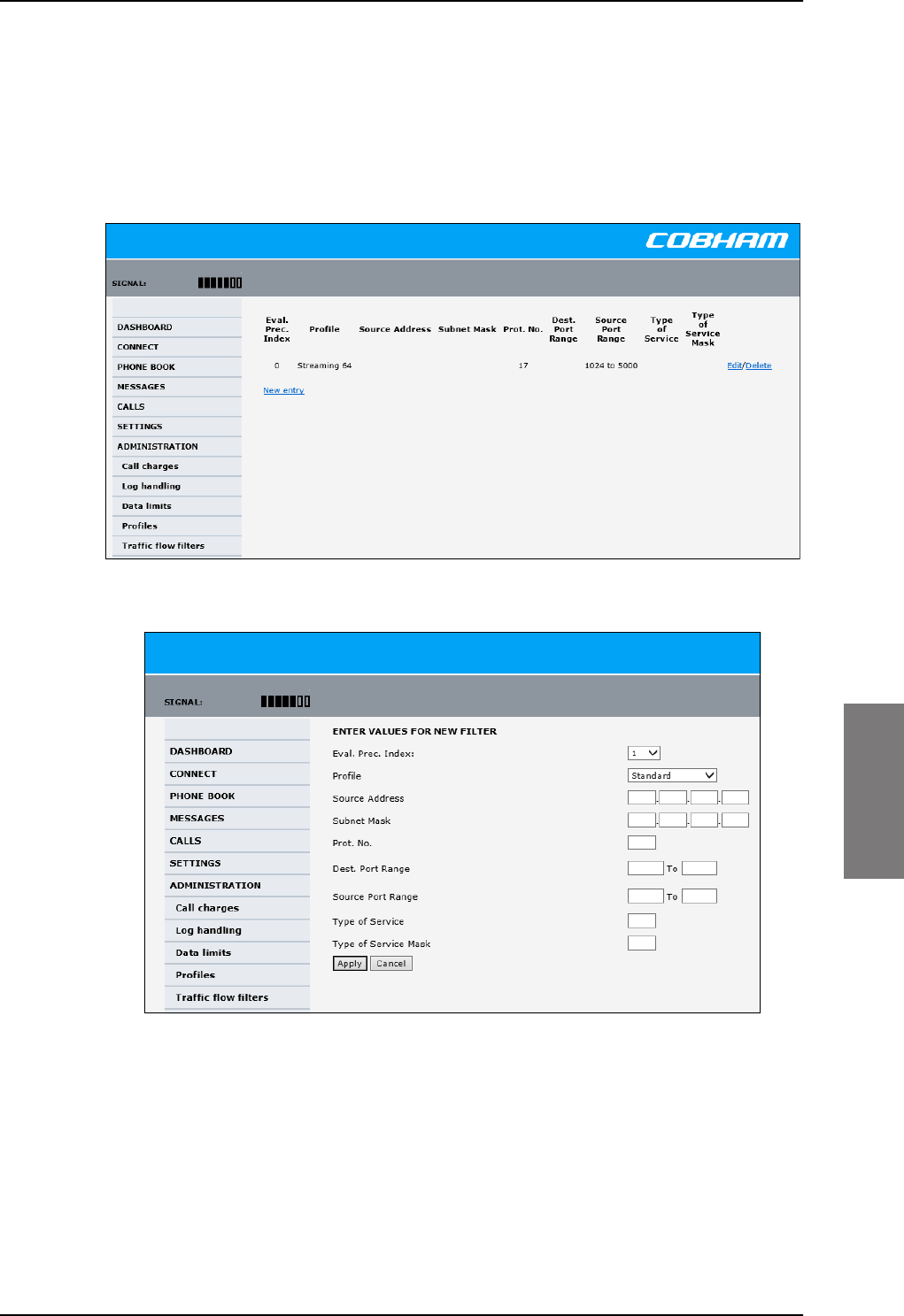
Administration
98-127093-H Chapter 6: Configuration of the AVIATOR 200/300/350 system 6-83
6666
Define traffic flow filters
To define the traffic flow filters, do as follows:
1. From the left navigation pane, select
ADMINISTRATION > Traffic flow filters. The example below shows one traffic
flow filter.
2. Click the link New entry.
Figure 6-66: Web interface: Administration, Traffic flow filters, New entry
3. Select a number in the Eval.Prec. Index drop-down list.
The evaluation precedence index defines the order in which the traffic flow filters are
applied to packets. 0 is first, then 1, 2 etc.
4. Select the Profile from the drop-down list.
The available profiles are the profiles listed under ADMINISTRATION > Profiles. The
selected profile is applied to all traffic that matches the conditions entered in step 5.
Figure 6-65: Web interface: Administration, Traffic flow filters
SB-Lite.book Page 83 Tuesday, September 5, 2017 1:38 PM
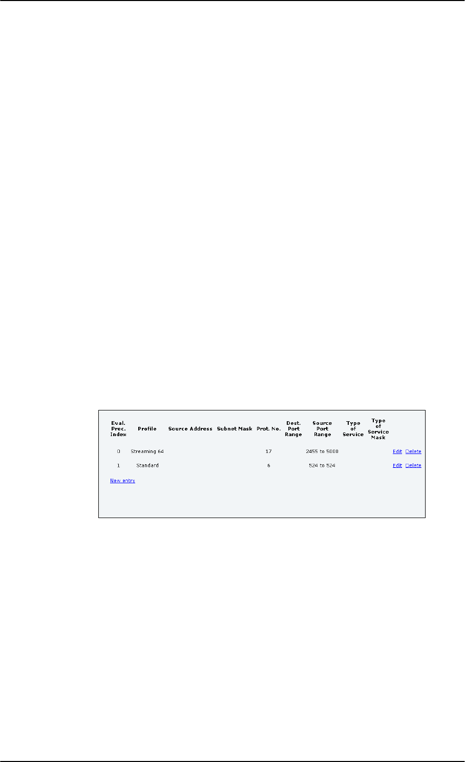
Administration
6-84 Chapter 6: Configuration of the AVIATOR 200/300/350 system 98-127093-H
5. Fill in one or more of the following fields to define the filter.
The allowed ranges appear in hover text when you pass the mouse over the fields.
•Source address + Subnet mask.
This is an IPv4 IP address and subnet mask. Only packets received from the specified
source are accepted by the filter.
•Protocol number.
This is uniquely assigned for the protocol being used. For TCP (typically Internet, e-
mail, FTP) set this to 6, for UDP (typically streaming) to 17. The protocol number
determines which protocol is used by the traffic flow filter.
•Destination port range (From and To). This parameter requires knowledge of ports
being used by the selected applications. Note that Source and Destination are
relative to the BGAN core network. This means that Destination is your SBU.
•Source port range (From and To). This parameter requires knowledge of ports
being used by the selected applications. Note that you must fill in both From and To,
even if there is only one port.
•Type of Service + Type of Service mask.
Set this value to a number between 0 and 255.
Type of Service (TOS) is an 8-bit field in a packet header, with associated mask, that is
used to define Quality of Service.
For further information on the principles and parameters of the traffic flow filters, refer
to the 3GPP standards TS27.007 V4.2.0 and TS 23.060 V4.7.0.
6. Click Apply at the bottom of the page.
Example of a list of traffic flow filters
Below is an example of a list with two traffic flow filters.
Figure 6-67: Web interface: Example of two traffic flow filters
In this example, data packets are filtered in the following order:
1. The filter with evaluation precedence index 0 checks for UDP packets (protocol number
17), in the port range 2455-5000. When these packets are identified, they are assigned
a 64 kbps Streaming channel (the Streaming 64 profile).
2. The filter with evaluation precedence index 1 checks remaining packets for TCP packets
(protocol number 6), on port 524. These packets are routed to the standard IP
connection (the Standard profile).
3. Remaining traffic is routed to the standard IP connection.
SB-Lite.book Page 84 Tuesday, September 5, 2017 1:38 PM
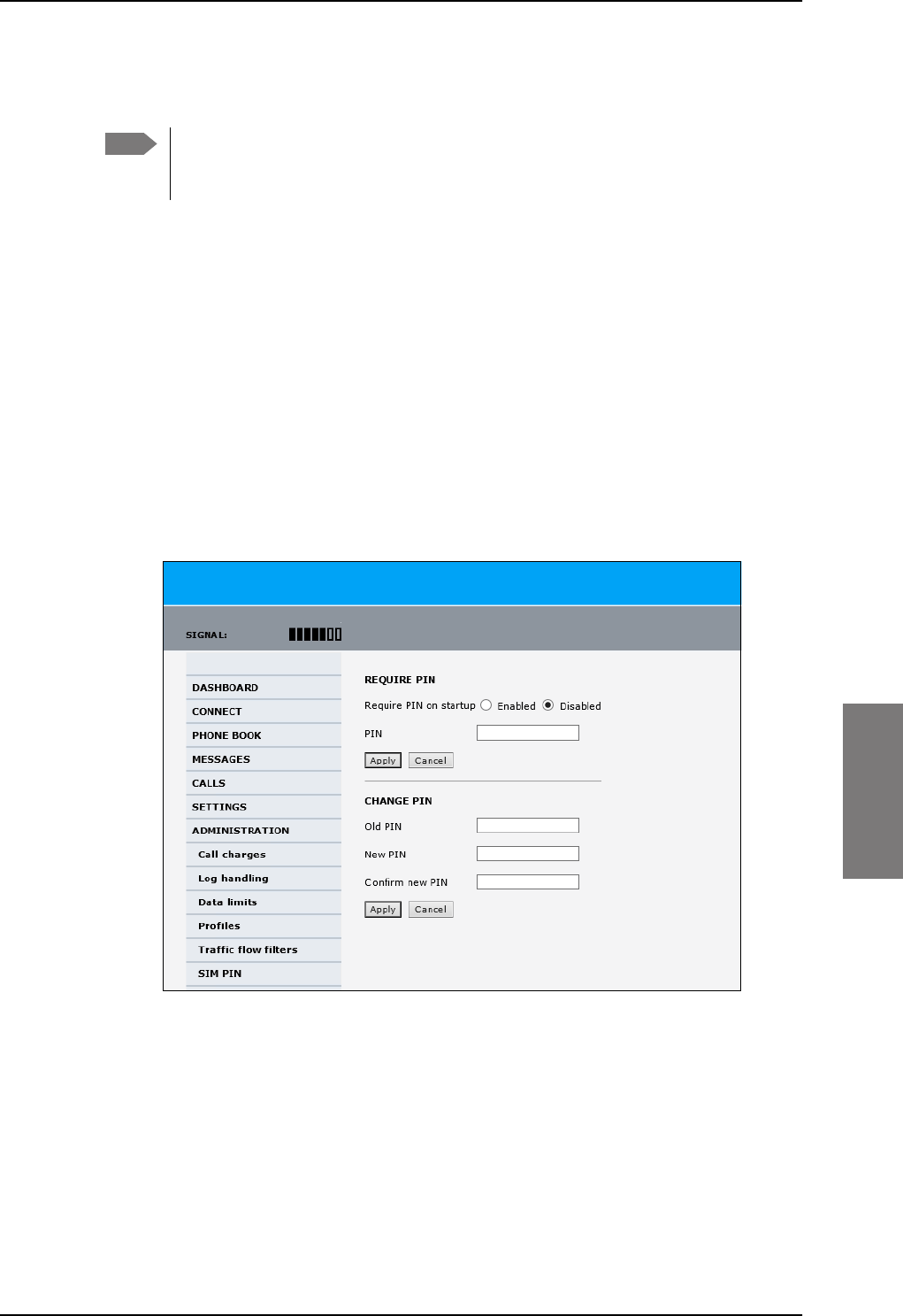
Administration
98-127093-H Chapter 6: Configuration of the AVIATOR 200/300/350 system 6-85
6666
6.7.9 SIM card access protection: SIM PIN and SIM Lock
SIM PIN
To avoid unauthorized use of the system you can enable the SIM PIN. Then the user has to
enter the SIM PIN before being able to use the system. The SIM PIN is disabled per default.
You enable the SIM PIN in the web interface. You can also specify a new SIM PIN in the
web interface. To do this you have to enter the original SIM PIN and then specify a new
one.
To manage the SIM PIN of the terminal do as follows:
1. From the left navigation pane, select ADMINSTRATION > SIM PIN.
2. If you want to protect the system with a system SIM PIN select Enabled.
3. You can enter a new PIN or change the existing PIN.
4. Click Apply to save the changes.
Figure 6-68: Web interface, Administration, SIM PIN
Note There is typically no SIM PIN needed for the AVIATOR 200/300/350 system. The
following functions might apply for special airtime subscriptions that have a SIM
PIN.
SB-Lite.book Page 85 Tuesday, September 5, 2017 1:38 PM
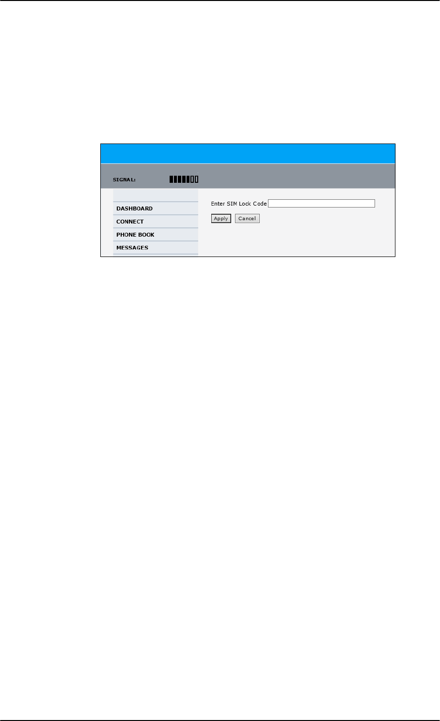
Administration
6-86 Chapter 6: Configuration of the AVIATOR 200/300/350 system 98-127093-H
SIM Lock
The supplier may lock the SIM card of the terminal to a specific service provider. For further
information contact your supplier. To unlock the SIM lock of the SIM card from your
airtime provider do as follows:
1. From the left navigation pane, select ADMINSTRATION > SIM LOCK.
2. Enter the SIM Lock Code and click Apply.
Figure 6-69: Web interface, Administration, SIM LOCK
SB-Lite.book Page 86 Tuesday, September 5, 2017 1:38 PM
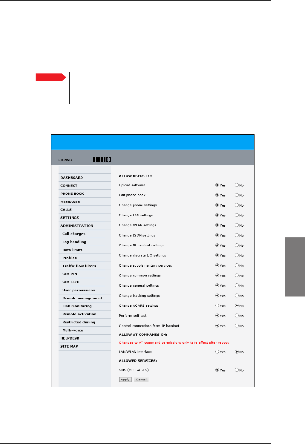
Administration
98-127093-H Chapter 6: Configuration of the AVIATOR 200/300/350 system 6-87
6666
6.7.10 Set up user permissions
You can manage user access to certain functions of the AVIATOR 200/300/350 system.
You can allow or deny users that are not administrators access to certain functions and
make these pages read-only. This is useful if you want to protect the system against
unintended changes or tampering of the system.
Protect the SBU against unintended change of setup. We recommend to
study the following screen thoroughly and decide which areas of the
AVIATOR 200/300/350 system you want to give non-administrator users
access to.
To set up the user permissions, do as follows:
1. From the left navigation pane, select ADMINISTRATION > User permissions.
Figure 6-70: Web interface: Administration, User permissions
2. For each item under ALLOW USERS TO:, select
•Yes to allow access
Important
SB-Lite.book Page 87 Tuesday, September 5, 2017 1:38 PM

Administration
6-88 Chapter 6: Configuration of the AVIATOR 200/300/350 system 98-127093-H
•No to block access to the settings. Then the pages are read-only for non-
administrators. The settings on the page cannot be changed.
3. Under ALLOW AT COMMANDS ON: select
•Yes to allow the use of AT commands on the LAN/WLAN interface
•No to block the use of AT commands on the LAN/WLAN interface
AT commands are typically used during maintenance and service.
4. Under ALLOWED SERVICES select:
•Yes to allow that the user can send and receive text messages
•No to block sending and receiving text messages. Note that the menu item
MESSAGES is not displayed any longer.
5. Click Apply.
The settings to which access is denied are now greyed out for the non-administrator
user.
Note This setting does not take effect until the SBU is restarted.
SB-Lite.book Page 88 Tuesday, September 5, 2017 1:38 PM
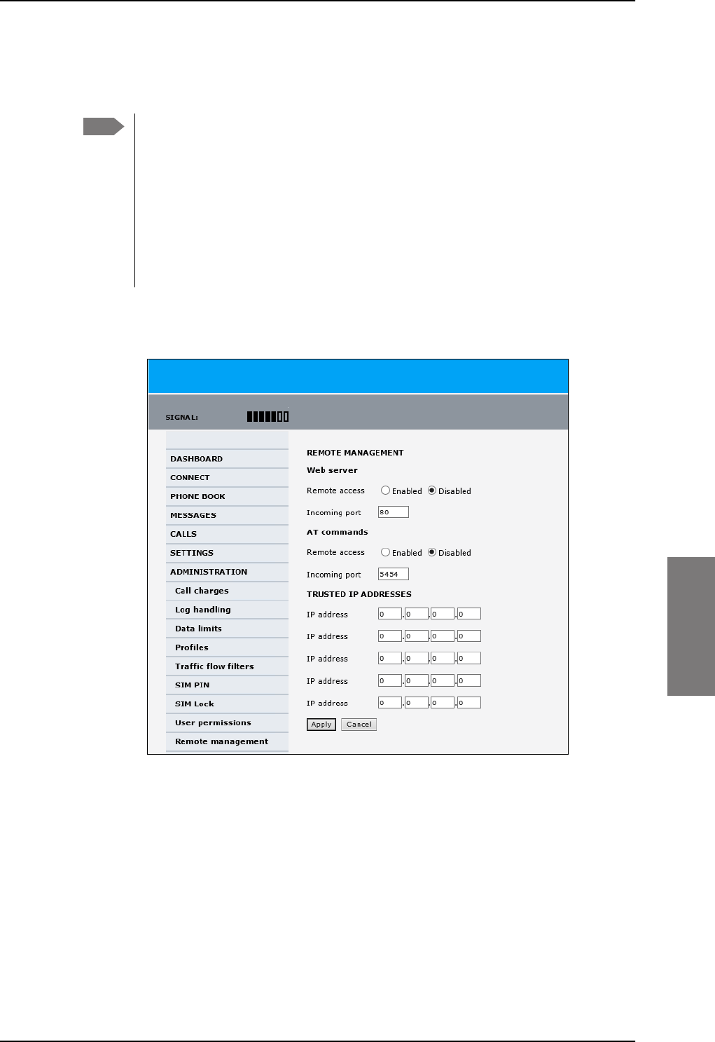
Administration
98-127093-H Chapter 6: Configuration of the AVIATOR 200/300/350 system 6-89
6666
6.7.11 Remote management
You can set up the SBU for control from a remote location.
If you want to remotely control the SBU, it must have activated a connection. This
can be done in several ways:
• Automatic activation of a Standard data connection, see step 10 on page 6-61
in Edit a network user group.
• Manual start of a data connection (Standard data or Streaming, see Start or
stop a standard data connection on page 6-14)
• Remote start of a data connection with an SMS, see Remote activation of a
connection using SMS on page 6-90.
To set up the SBU for remote management, do as follows:
1. From the left navigation pane, select ADMINISTRATION > Remote management.
Figure 6-71: Web interface: Administration, Remote management
2. Select whether remote access using a web server should be Enabled or Disabled and
enter the Incoming port number.
3. Select whether AT commands should be Enabled or Disabled and enter the
Incoming port number.
4. Under TRUSTED IP ADDRESSES, type in the IP addresses of the devices you want to
give access to the SBU.
5. Click Apply to save the new settings.
You can now access the SBU from one of the trusted IP addresses, using the incoming port
defined in the Incoming port field. For a detailed description how to access the SBU from
a remote location see the AVIATOR 200/300/350 user manual.
Note
SB-Lite.book Page 89 Tuesday, September 5, 2017 1:38 PM
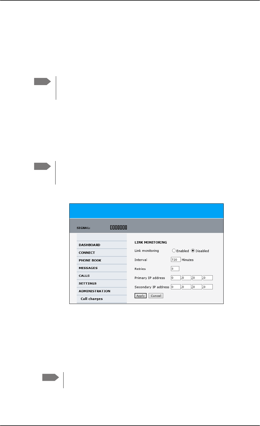
Administration
6-90 Chapter 6: Configuration of the AVIATOR 200/300/350 system 98-127093-H
6.7.12 Remote activation of a connection using SMS
If you want to remotely control the SBU, it must have activated a connection. You can do
this by sending an SMS to the SBU. The SBU must be powered up and logged on to the
satellite services to receive the SMS and then start the connection. For a detailed
description how to activate a connection using SMS see the AVIATOR 200/300/350 user
manual.
The SBU must be logged on to the satellite services to receive and accept an
activation SMS. If the SMS is considered too old or sent before the SBU has been
switched on and has logged on, the SMS will be ignored.
6.7.13 Link monitoring (SwiftBroadband only)
You can monitor the external SwiftBroadband IP connection of the AVIATOR system using
the link monitoring feature. With this feature activated, the terminal will send out ping
commands (ICMP Echo Requests) to a server of your choice.
Link monitoring is only performed on data connections with the Default network
user group (see Set up the network user groups on page 6-59). This data
connection must be activated before link monitoring can start.
To set up link monitoring, do as follows:
1. From the left navigation pane, select ADMINISTRATION > Link monitoring.
2. Select Enabled if you want to enable Link monitoring.
3. Select the Interval between each ping.
4. Select the number of Retries before the terminal reboots.
5. Type in the Primary and optionally the Secondary IP address.
This is the IP address of the server(s) to which the terminal will send ping commands.
6. Click Apply.
Note
Note
Figure 6-72: Web interface: Administration, Link monitoring
Note Use a server that is reliable and that supports and responds to ICMP Echo
Requests.
SB-Lite.book Page 90 Tuesday, September 5, 2017 1:38 PM
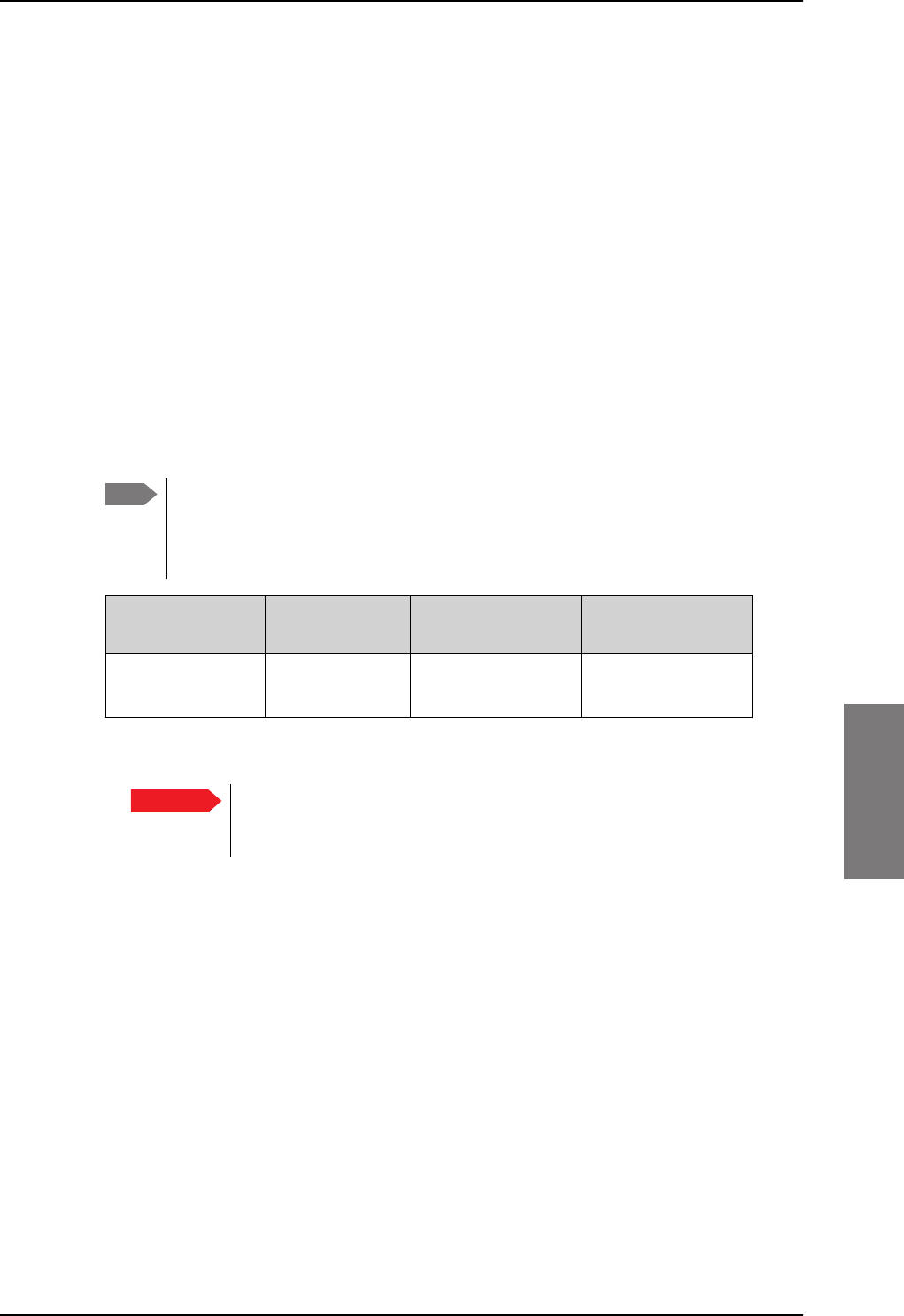
Administration
98-127093-H Chapter 6: Configuration of the AVIATOR 200/300/350 system 6-91
6666
When a data session is started with the Default network user group, the terminal will start
sending ping commands to the Primary IP address the number of times specified at
Retries. If no response is received, it will send the same number of ping commands to the
Secondary IP address, if available. If no response is received here either, the terminal will
reboot.
6.7.14 Restricted dialing
In order to manage the use of the AVIATOR 200/300/350 system efficiently you can set up
the SBU to limit all calls to allowed numbers or numbers in the phone book. This feature can
be enabled for each connected handset separately. For a detailed description how to
restrict dialing see the AVIATOR 200/300/350 user manual.
6.7.15 Multi-voice (option)
You can subscribe to Multi-voice with or without additional numbers. Multi-voice is
disabled per default.
You must have Multi-voice in your airtime subscription, AVIATOR Wireless
Handset software version minimum 1.03 and SBU software version minimum
AVIATOR 200/300/350 (Level E): 1.07, AVIATOR 200D/300D/350D (Level D):
2.01, in order to support the Multi-voice function.
Table 6-10: Multi-voice, number of calls
Multi-voice AVIATOR 200
LGA (Class 15)
AVIATOR 300 IGA
(Class 7)
AVIATOR 350 HGA
(Class 6)
Number of voice
calls
2 (best effort
quality)
Up to 9 (best effort
quality)
Up to 9 (best effort
quality)
To enable Multi-voice, do as follows:
1. Enter the web interface of your terminal.
2. Select Administration > Multi-voice.
3. Select Multi-voice.
If you want to use an external PBX, select Using external Multi-voice PBX and
select the interface used to connect the PBX to the terminal
You are now ready to use Multi-voice. For more detailed information about configuring
Multi-voice see Configure Multi-voice on page 6-95.
Note
Important For software 4.00 and higher and SB-Safety Voice: Do not enable Multi-
voice. Multi-voice is disabled automatically when enabling SB-Safety
Voice.
SB-Lite.book Page 91 Tuesday, September 5, 2017 1:38 PM

Administration
6-92 Chapter 6: Configuration of the AVIATOR 200/300/350 system 98-127093-H
Rules for concurrent calls (without cockpit reserve)
• First call initiated: You can use any connected handset and any call type for incoming as
well as outgoing calls.
• Second and subsequent calls: You can only use handsets connected to the WLAN
interface for calls initiated/received while another call is active. The call type for the
second and subsequent calls is always Standard Voice.
Additional numbers for Multi-voice
In addition to the phone numbers for incoming Standard Voice, and 3.1 kHz Audio and
UDI/RDI, your subscription may include extra phone numbers that can be assigned to
specific handsets. If you want to use the additional phone numbers in your subscription,
you must set up the following in the web interface:
• Enable the use of additional numbers in the web interface under ADMINISTRATION >
Multi-voice. See Configure Multi-voice on page 6-95.
• Add the additional numbers from your airtime subscription under PHONE BOOK >
MOBILE NUMBERS > ADDITIONAL NUMBERS.
• Assign the numbers to handsets. Depending on the handset interface you want to use,
see the pages SETTINGS > Phone/Fax, SETTINGS > ISDN or SETTINGS > IP
handsets in the web interface.
Check with your service provider for individual billing of an additional number.
Handset contexts
Calls to the SBU are treated differently depending on the handset context. If additional
numbers are used, there are 3 possible handset contexts, which are explained in this
section:
•Call type groups
•Directly assigned handsets
•Unassigned handsets
Call type groups
The handsets are called using one of the mobile numbers for either Standard Voice or
3.1
kHz audio. All handsets in a group will ring when the belonging number is called.
For information on how to associate a handset with a group, see
•Set the call types for AVIATOR Wireless Handsets on page 6-36
•Configure the Phone/Fax interface (2-Wire) on page 6-24
•Configure the ISDN interface on page 6-25
Note If you have additional numbers in your airtime subscription, you must set up how
the system should use them. See the sections Handset contexts on page 6-92.
Note You must have Multi-voice with additional numbers in your airtime subscription to
be able to use this feature.
SB-Lite.book Page 92 Tuesday, September 5, 2017 1:38 PM
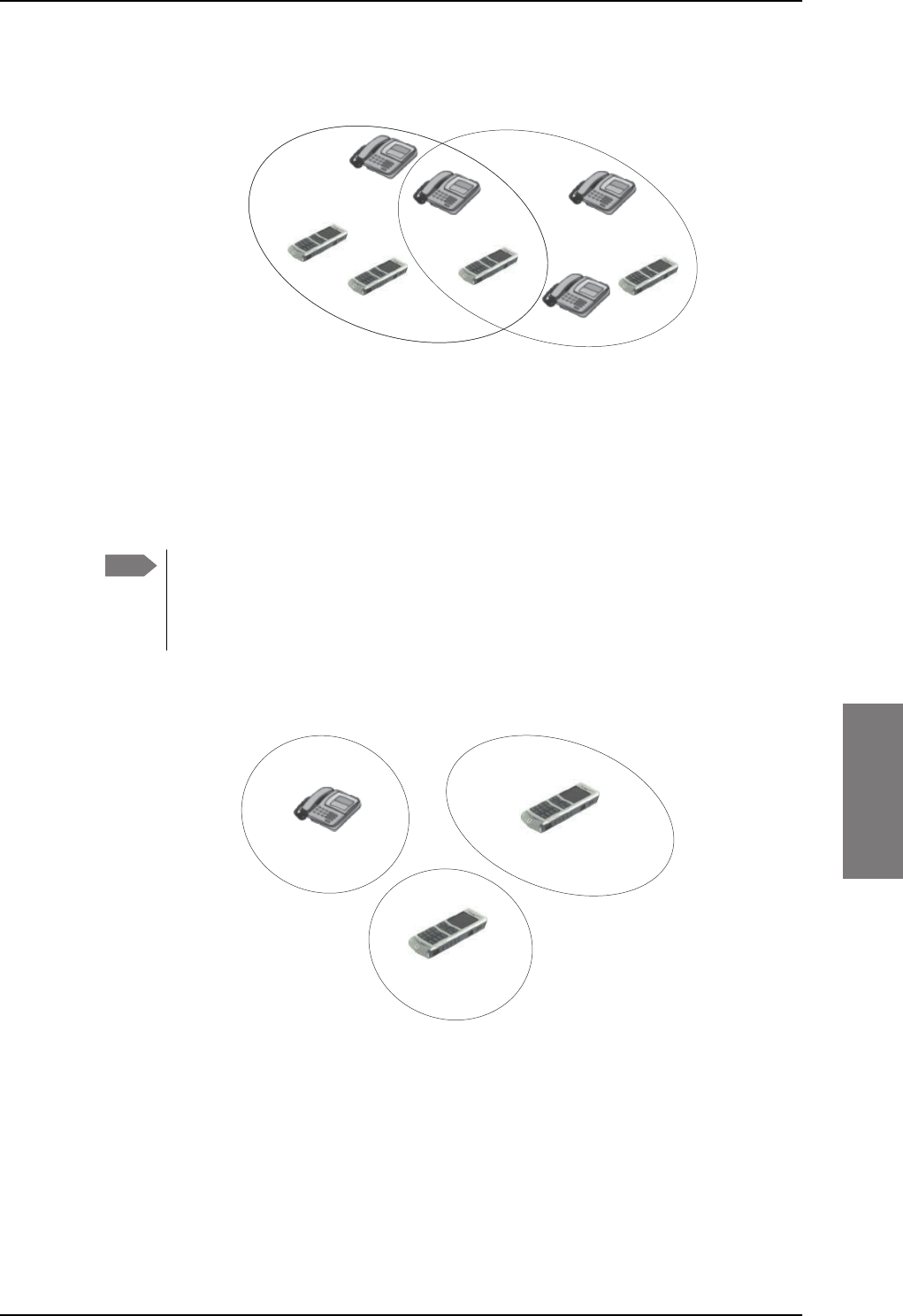
Administration
98-127093-H Chapter 6: Configuration of the AVIATOR 200/300/350 system 6-93
6666
Directly assigned handsets
The mobile numbers are assigned to individual handsets. Only the assigned handset will ring
when the associated number is called.
For information on how to assign a number to a handset, see the pages SETTINGS >
Phone/Fax, SETTINGS > ISDN or SETTINGS > IP handsets in the web interface.
Note that you can also assign the call type numbers directly (in the example above, the
Standard Voice number is assigned to IP handset number 0501). If you do so, be aware that
only the assigned handset can receive a call to this number. The handset connected to the
Phone port 1 and the IP handset no. 0502 are each assigned an additional number.
Figure 6-73: Multi-voice, call type groups (example)
&DOO7\SH 6WDQGDUG &DOO7\SH N+]
6WDQGDUG9RLFHQXPEHU
,6'13RUW
3KRQH)D[
3RUW
,6'13RUW
3KRQH)D[
3RUW
N+]$XGLRQXPEHU
[
Note To use this feature you must have additional numbers in your airtime subscription
and enable the use of additional numbers in the web interface. Then you can
assign the numbers to individual handsets. For details on additional numbers, see
Additional numbers for Multi-voice on page 6-92.
Figure 6-74: Multi-voice, example of directly assigned handsets (example)
,3KDQGVHWORFDOQR
$GGLWLRQDOQXPEHU
&DELQ
,3KDQGVHWORFDOQR
6WDQGDUG9RLFHQXPEHU
3DQWU\
3KRQH)D[SRUW
$GGLWLRQDOQXPEHU
&RFNSLW
SB-Lite.book Page 93 Tuesday, September 5, 2017 1:38 PM
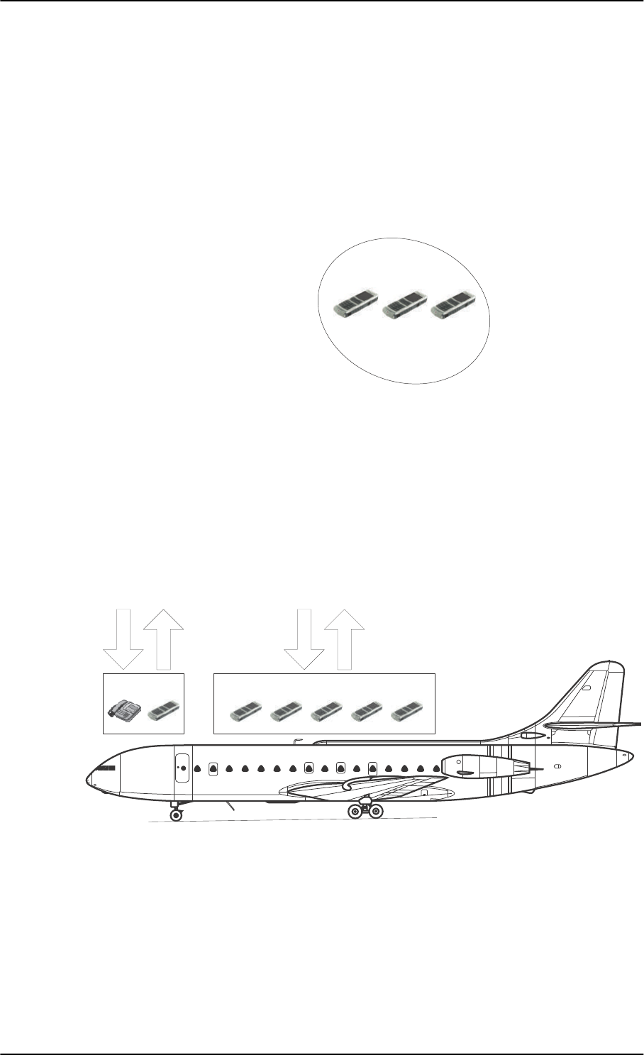
Administration
6-94 Chapter 6: Configuration of the AVIATOR 200/300/350 system 98-127093-H
Unassigned handsets
These are IP handsets that are not assigned a number, and that do not belong to a call type
group. Use this handset context if you want to create a group of IP handsets that can be
called together. All unassigned IP handsets will ring when you call a mobile number which
has not been assigned to a handset.
To make an IP handset unassigned, clear all call types and the Assigned number field when
setting up the handsets in the web interface. See Set the call types for AVIATOR Wireless
Handsets on page 6-36.
Figure 6-75: Multi-voice, example of unassigned handsets
Cockpit reserve
With Cockpit reserve enabled, is it possible to reserve at least one call line to the handsets in
the cockpit. The free call line is reserved for all handsets not assigned an additional Multi-
voice number.
In the following example of a Multi-voice configuration with cockpit reserve, all handsets in
the cabin have been assigned an additional number while the handsets in the cockpit
belong to the standard call type group.
Figure 6-76: Multi-voice, example for a configuration with Cockpit reserve.
&DELQ
,3KDQGVHWORFDOQR
1RQXPEHUDVVLJQHG
All handsets ring
when calling a mobile
number which is in
the subscription but
not assigned to any
handset.
&RFNSLW
&DOOW\SHJURXS
&DELQ
$GGLWLRQDOQXPEHUDVVLJQHGWRHDFK,3KDQGVHW
0RELOHQXPEHUV
$GGLWLRQDOQXPEHUV
$GGLWLRQDOQXPEHUV
0RELOHQXPEHUV
SB-Lite.book Page 94 Tuesday, September 5, 2017 1:38 PM
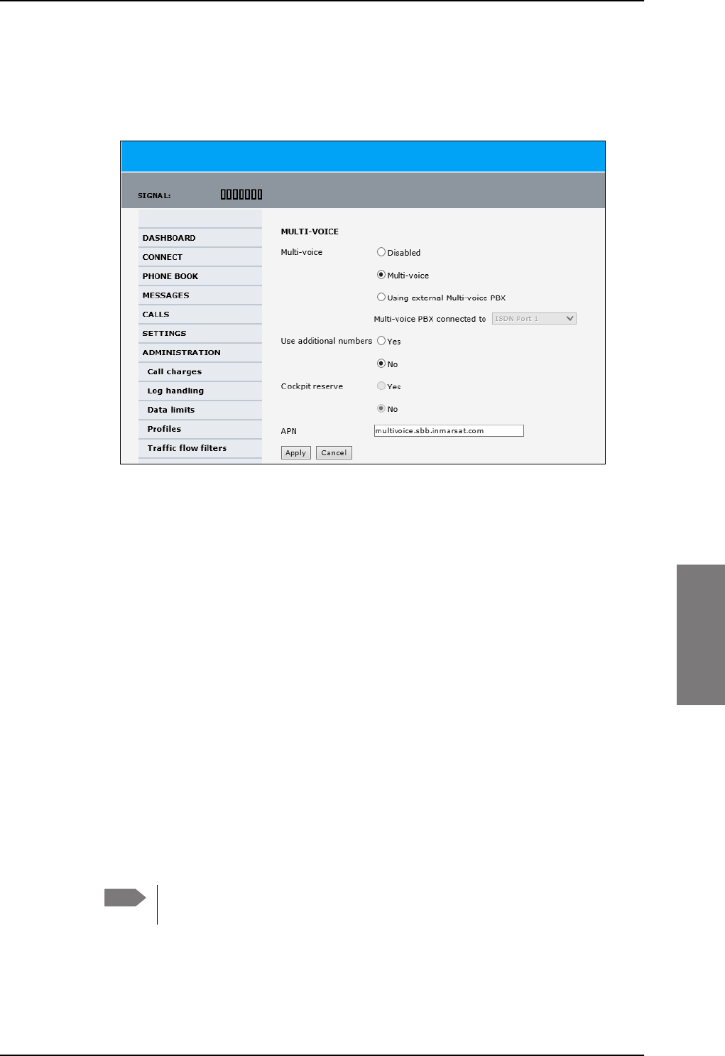
Administration
98-127093-H Chapter 6: Configuration of the AVIATOR 200/300/350 system 6-95
6666
Configure Multi-voice
To enable and configure Multi-voice, do as follows:
1. From the left navigation pane, select Administration > Multi-voice.
Figure 6-77: Web interface: Administration, Multi-voice
2. To use the AVIATOR 200/300/350 terminal for Multi-voice, select Multi-voice.
You can also use an external Multi-voice PBX. If so, select Using external Multi-
voice PBX and select the interface used to connect the PBX to the terminal. Refer to
the manufacturer documentation for your Multi-voice PBX.
3. If you want to assign additional numbers, select Use additional numbers. You must
have additional numbers in your subscription and enter the additional numbers under
PHONE BOOK > Mobile numbers. (See also Set up additional numbers on page 6-
96.)
Then you can use the setup page for the handset interface, e.g. SETTINGS > IP
handsets > Call settings, to assign the additional numbers to the handsets you want
to be able to call directly. (See also Assign additional numbers on page 6-97).
4. You can configure a reserved line for the handsets in the cockpit by selecting Use
additional numbers and Cockpit reserve Yes.
• There will at all times be a free line for the handsets in the cockpit so a call can be
made and received regardless the use of other handsets. Set up a call type group to
assign handsets to the cockpit-reserved group, see Set the call types for AVIATOR
Wireless Handsets on page 6-36, Configure the Phone/Fax interface (2-Wire) on
page 6-24 and Configure the ISDN interface on page 6-25.
• Use the additional numbers for other handsets, e.g. in the cabin.
5. Type in the VoIP APN used for Multi-voice. You find the Multi-voice APN name in your
subscription documentation.
6. Click Apply.
Note The handsets using additional numbers must be AVIATOR Wireless Handsets or
other SIP phones, a normal 2-wire handset cannot be used.
SB-Lite.book Page 95 Tuesday, September 5, 2017 1:38 PM
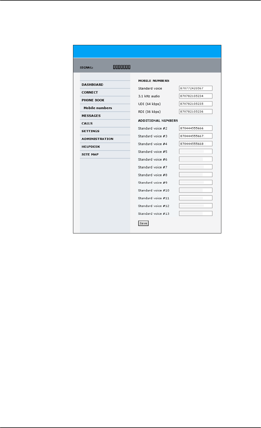
Administration
6-96 Chapter 6: Configuration of the AVIATOR 200/300/350 system 98-127093-H
Set up additional numbers
Enter the additional numbers under PHONE BOOK > Mobile numbers.
Figure 6-78: Web interface: Phone book, mobile numbers (example, Multi-voice)
SB-Lite.book Page 96 Tuesday, September 5, 2017 1:38 PM
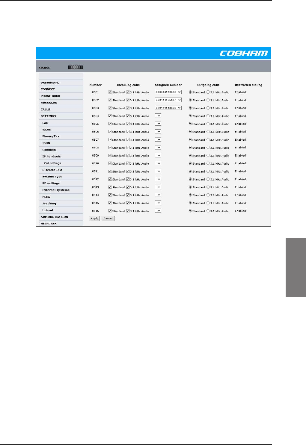
Administration
98-127093-H Chapter 6: Configuration of the AVIATOR 200/300/350 system 6-97
6666
Assign additional numbers
Assign additional numbers under SETTINGS > IP handsets > Call settings.
Figure 6-79: Web interface: Settings, IP handsets, Call settings (with Multi-voice, example)
SB-Lite.book Page 97 Tuesday, September 5, 2017 1:38 PM
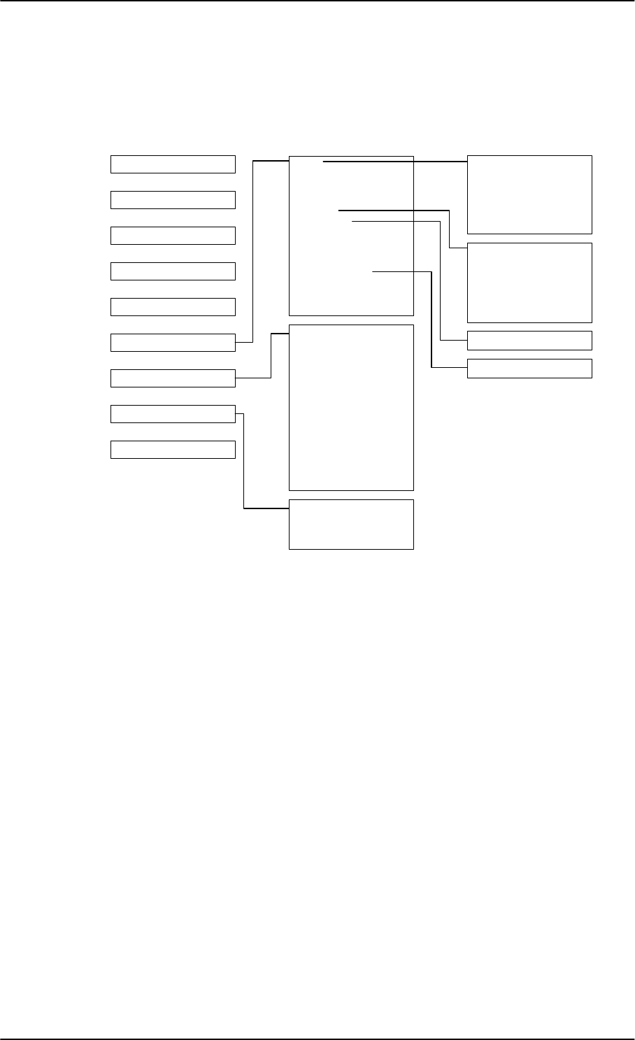
Site map
6-98 Chapter 6: Configuration of the AVIATOR 200/300/350 system 98-127093-H
6.8 Site map
The web interface offers a site map page. Use this page to get an overview over the menus,
submenus and topics. The following drawing shows the site map
Figure 6-80: Web interface: Site map
.
To access the site map, select SITE MAP from the left navigation pane. You can click on
each menu in the site map to go directly to the page or display the respective submenu.
3RUWIRUZDUGLQJ
1HWZRUNGHYLFHV
1HWZRUNFODVVLILFDWLRQ
1HWZRUNXVHUJURXSV
333R(
6WDWLFURXWH
&DOOIRUZDUG
&DOOEDUULQJ
&DOOZDLWLQJ
/LQHLGHQWLILFDWLRQ
&ORVHGXVHUJURXS
/RFDOH[FKDQJH
/$1
:/$1
3KRQH)D[
,6'1
&RPPRQ
,3KDQGVHWV
'LVFUHWH,2
6\VWHPW\SH
5)VHWWLQJV
([WHUQDOV\VWHPV
)/(;
7UDFNLQJ
8SORDG
&DOOFKDUJHV
/RJKDQGOLQJ
'DWDOLPLWV
3URILOHV
7UDIILFIORZILOWHUV
6,03,1
6,0/RFN
8VHUSHUPLVVLRQV
5HPRWHPDQDJHPHQW
/LQNPRQLWRULQJ
5HPRWHDFWLYDWLRQ
5HVWULFWHGGLDOLQJ
0XOWLYRLFH
(YHQWOLVW
(YHQWORJ
([WHQGHGVWDWXV
6HOIWHVW
'$6+%2$5'
&211(&7
3+21(%22.
0(66$*(6
&$//6
6(77,1*6
$'0,1,675$7,21
+(/3'(6.
6,7(0$3
&DOOVHWWLQJV
&08$&$56
SB-Lite.book Page 98 Tuesday, September 5, 2017 1:38 PM

Configuration of 3rd party phone systems
98-127093-H Chapter 6: Configuration of the AVIATOR 200/300/350 system 6-99
6666
6.9 Configuration of 3rd party phone systems
6.9.1 Sigma7 setup
There are a few adjustments that are typically made at the time of installation testing.
Normally it is necessary to set the ear volume of the handset initially, in order to obtain
sufficient volume in the ear piece.
The information in this section is only meant as a guideline. For complete
information on the function of the Sigma7 handset, refer to the Sigma7 manual.
To set up the ear volume
To set up the ear volume of the handset, do as follows:
1. Take the handset out of the cradle and enter the menu system of the handset.
2. Use the volume control keys to scroll to the EARVOL setting.
3. Press the Flash key to select EARVOL.
4. Change the volume setting to 4 using the volume control keys.
5. Press # to store the setting. To adjust other settings, press Flash to return to the menu.
6. Place the handset back into the cradle.
For further information on the Sigma7 handset, refer to the manual for the Sigma7 handset.
6.9.2 ICG DECT Cordless Handset setup
It is sometimes necessary to adjust the volume of the ICG DECT Cordless Handset, in order
to have sufficient volume in the ear piece. Also, you may want to change the setting of the
handset from pulse to tone, if this is not already set.
The information in this section is only meant as a guideline. For complete
information on the function of the ICG DECT Cordless Handset phone, refer to the
manual for your ICG DECT Cordless Handset phone.
To set the volume
To change the volume setting, enter the handset menus and do as follows:
1. Scroll to Audio Sett and press OK.
2. Select H/Set Vol and press OK. The current volume is heard in the ear piece and the
level is displayed.
3. Scroll to the desired volume and press OK.
To switch to Tone dialing
To change the dialing mode, do as follows:
1. Open the handset menu.
2. Scroll to Temp Tone and press OK. Tone dialing is now active.
Note
Note
SB-Lite.book Page 99 Tuesday, September 5, 2017 1:38 PM
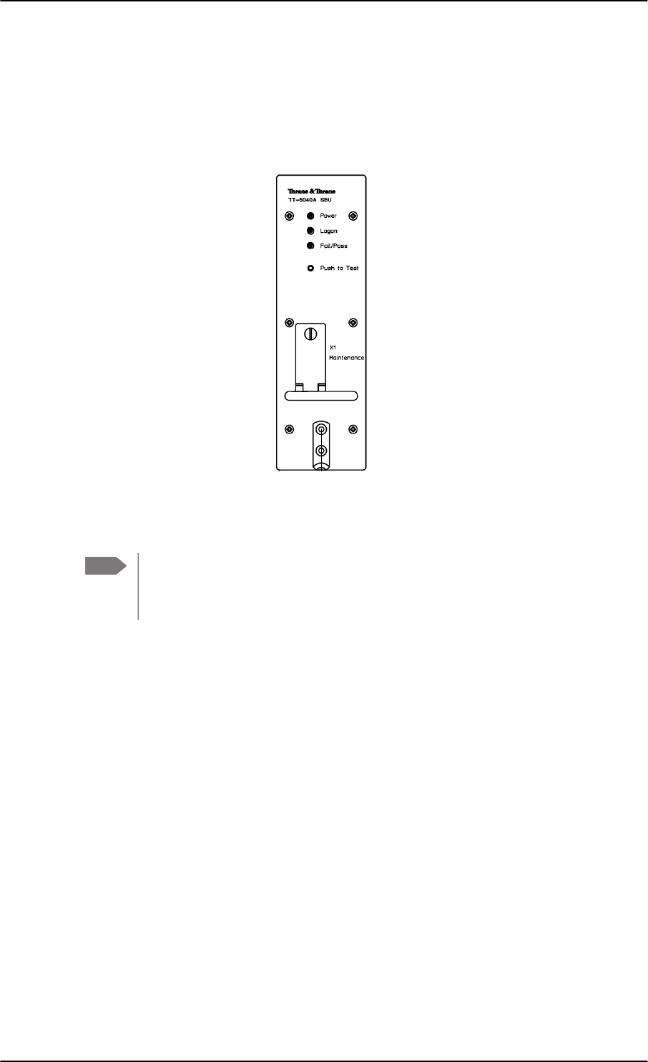
AVIATOR 200/300/350 system ready for use
6-100 Chapter 6: Configuration of the AVIATOR 200/300/350 system 98-127093-H
6.10 AVIATOR 200/300/350 system ready for use
Having installed the AVIATOR 200/300/350 system, activated the SIM card and configured
the system you can verify whether the system is fully operational. Check that all LEDs on
the SBU front panel are green.
Figure 6-81: AVIATOR 200/300/350 system
Note Line of sight during operation!
Make sure that there is a line of sight between the Satcom antenna and the
satellite in order to logon to and use the satellite service.
6%8
*UHHQ/('VRQ6%8
3RZHU
/RJRQ
)DLO3DVV
SB-Lite.book Page 100 Tuesday, September 5, 2017 1:38 PM

98-127093-H 7-1
Chapter 7
7777
Maintenance and troubleshooting 7
7.1 Continued Airworthiness
7.1.1 General
Maintenance
The AVIATOR system requires no periodic scheduled servicing tasks.
When replacing the TT-5040A SwiftBroadband Unit (SBU), it is important to
leave the TT-5040A-001 Configuration Module behind, attached to the airframe
with a wire.
Contact for support
AVIATOR 200/300/350 system purchased from a Cobham SATCOM distributor: If
you need assistance and you have purchased your system from a Cobham SATCOM
distributor, contact the distributor’s support line.
AVIATOR 200/300/350 system purchased directly from Cobham SATCOM: If you
need assistance and you have purchased your system directly from Cobham SATCOM, you
can contact Cobham SATCOM by telephone or send an e-mail to the Cobham SATCOM
esupport.
Telephone numbers:
For urgent technical support please contact us at one of the following numbers:
• One Dial Phone: +45 39 88 89 89
• US, Virginia Beach office: +1 757 463 9557 or +1 866 SATCOMS.
The eSupport e-mail address is AVIATOR.support@cobham.com.
7.1.2 Instructions
Documentation
Maintenance information for the AVIATOR 200/300/350 System is contained in this
manual. Place the wiring diagram information in this manual in the aircraft operator's
appropriate aircraft wiring diagram manuals.
Inoperative units
If a system component is inoperative, remove or replace the unit.
If a level-D certified system detects an inconsistent hardware unit (level E) or
software image (level E), it enters failure mode and the system will not be
operational. Inconsistency messages are displayed to clearly inform the
service personnel about the reason for this failure mode.
Note
Important
SB-Lite.book Page 1 Tuesday, September 5, 2017 1:38 PM

Continued Airworthiness
7-2 Chapter 7: Maintenance and troubleshooting 98-127093-H
If an inoperative SBU is removed, take out the TT-5040A-001 CM and fasten the CM and
wiring to the air frame. Secure all cables, collect applicable switches and circuit breakers,
and label them inoperative. Revise the equipment list and weight and balance as applicable
prior to flight and make a log book entry that the unit was removed.
For information on how to return a unit for repair, see Return units for repair on page 7-19.
Once repaired, reinstall the unit in the aircraft in accordance with the instructions in this
Installation and Maintenance Manual.
SB-Lite.book Page 2 Tuesday, September 5, 2017 1:38 PM
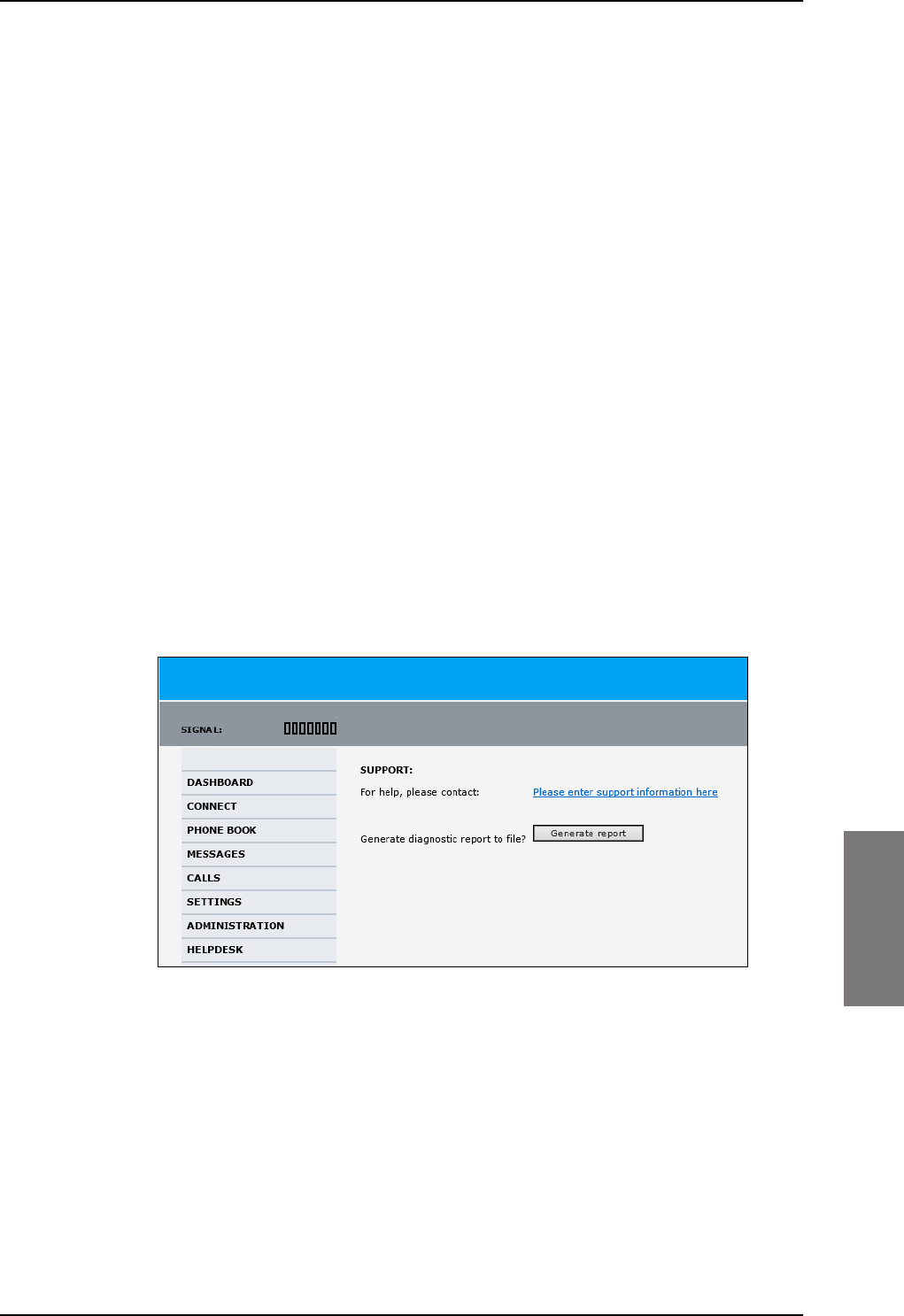
Get support: HELPDESK
98-127093-H Chapter 7: Maintenance and troubleshooting 7-3
7777
7.2 Get support: HELPDESK
If this manual does not provide the remedies to solve your problem, you may want to
contact your Airtime Provider or your local distributor.
7.2.1 Airtime support
If you need assistance from your Airtime Provider, call the help desk, click HELP DESK or
check your Airtime subscription for a contact number.
7.2.2 System support
If you need assistance with problems caused by the SBU or the antenna, please call a
distributor in your area. A list of certified partners and distributors is available on Cobham
SATCOM web site: www.cobham.com/satcom. Select Where to buy, then AVIATOR,
EXPLORER, SAILOR and Sea Tel branded products resellers.
7.2.3 Help desk and diagnostic report
Help desk
If you need help with airtime-related issues for the SwiftBroadband subscription you
may call the Help desk. Enter the phone number for your Airtime Provider on this page. To
access the Help desk, select HELP DESK from the left navigation pane.
Figure 7-1: Web interface: Help desk
If you have entered the Help desk number, it is displayed as a link. To change the number,
click the link, change the number and click Apply. If you need help with SBU- or
antenna-related issues call your local distributor.
SB-Lite.book Page 3 Tuesday, September 5, 2017 1:38 PM
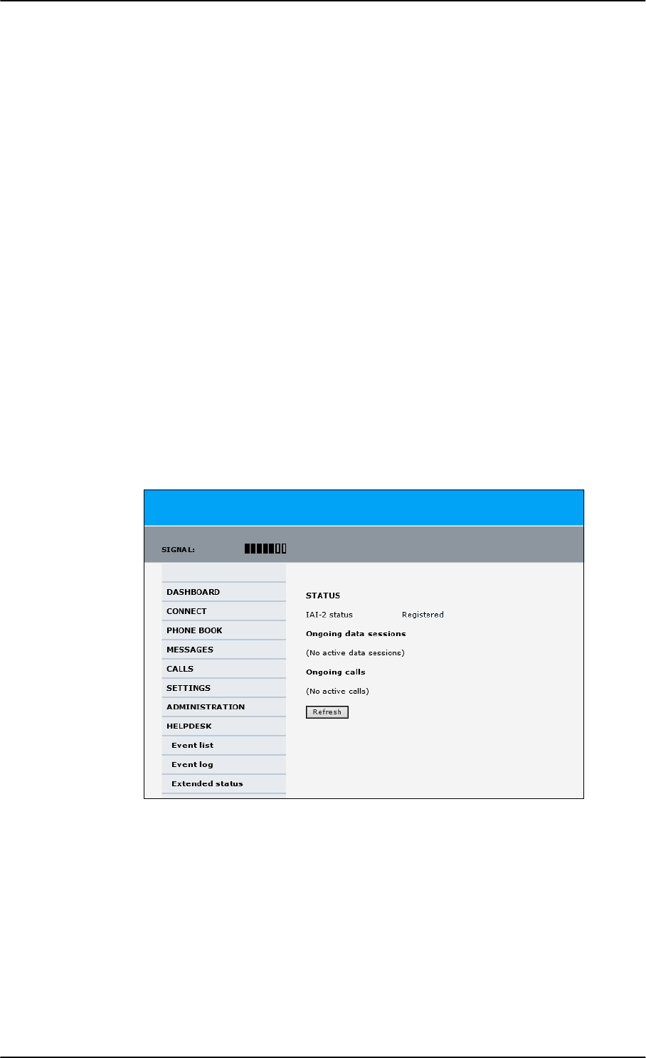
Get support: HELPDESK
7-4 Chapter 7: Maintenance and troubleshooting 98-127093-H
Generating a diagnostic report
When contacting your distributor for support, please include a diagnostic report. The
diagnostic report contains information relevant for the service personnel during
troubleshooting. When contacting your distributor for support, please enclose this file.
To generate a diagnostic report with valuable information for the service team, do as
follows:
1. Reboot the system.
2. Establish the problem or situation in which the error occurred, or
3. Make a CS call (if possible), i.e. making a call with a handset connected to the SBU.
4. Make a PS call (if possible), i.e. establish a data connection.
5. Click Generate report from the HELP DESK page.
In some browsers the file may open directly in your browser. If it does, choose File >
Save As to save the file.
6. Choose a location for the file and save it on your computer.
Extended status
Click Extended status in the HELP DESK page to display further status information on
logon status, ongoing data sessions and ongoing calls.
Figure 7-2: Web interface: Help desk, Extended status
SB-Lite.book Page 4 Tuesday, September 5, 2017 1:38 PM

Software update
98-127093-H Chapter 7: Maintenance and troubleshooting 7-5
7777
7.3 Software update
Minimum Software Version required for AVIATOR 200/300/350 (Level E):
• SBU: AVIATOR 200/300/350: Swift_broadband-E_105.zip
File: Swift_broadband-E_105.dl1
Minimum Software Version required for AVIATOR 200D/300D/350D (Level D):
• SBU: AVIATOR 200D/300D/350D: Swift_broadband-D_200.zip
File: Swift_broadband-D_200.dl
Hardware and software requirements
The following items are required before the software can be updated:
• One computer with a standard Ethernet port available.
• A standard Internet browser.
• 1024×768 pixels or higher display resolution. The program is best viewed using small
fonts.
• One straight LAN cable.
• The zipped file containing the new software.
• Select Product software > Aeronautical > Satcom Systems to narrow the search.
Important Level-D and Level E consistency!
A level-D certified system detecting an inconsistent hardware unit or
software image enters failure mode, and the system will not be operational.
Inconsistency messages clearly inform the service personnel about the
reason for this failure mode.
Pay great attention to selecting the correct software file: Level D or Level E. A
mismatch of Level D and Level E software is not allowed and will
result in a non-functioning system. A mismatch will be displayed in the
built-in web interface.
1. For Level E, this software version is not mandatory, but recommended.
SB-Lite.book Page 5 Tuesday, September 5, 2017 1:38 PM

Software update
7-6 Chapter 7: Maintenance and troubleshooting 98-127093-H
7.3.1 SBU software update
Preparing the software update
1. On the PC, unzip the zip file containing the new software. Remember or write down
which folder you extracted the file to.
2. Connect the SBU to the PC LAN port, using the SBU maintenance connector and a
straight LAN cable.
3. Power on the AVIATOR 200/300/350 system.
4. Open your browser and enter the IP address of the SBU. The standard IP address is
192.168.0.1.
If the local IP address of the SBU has been changed and you do not have the
new address, you can temporarily set the IP address to the default value by
pushing the Reset button next on the front plate of the SBU. For detailed
instructions see How to reset the IP address or the terminal software to
default settings on page 7-15.
For further information on the Reset button, see IP Reset (Default) button on
page 7-14.
For further information on IP addresses of the SBU see Set up the LAN IP
addressing on page 6-19.
You are now connected to the web interface of the SBU.
Note Software update should only be done by qualified service personnel.
Note
SB-Lite.book Page 6 Tuesday, September 5, 2017 1:38 PM
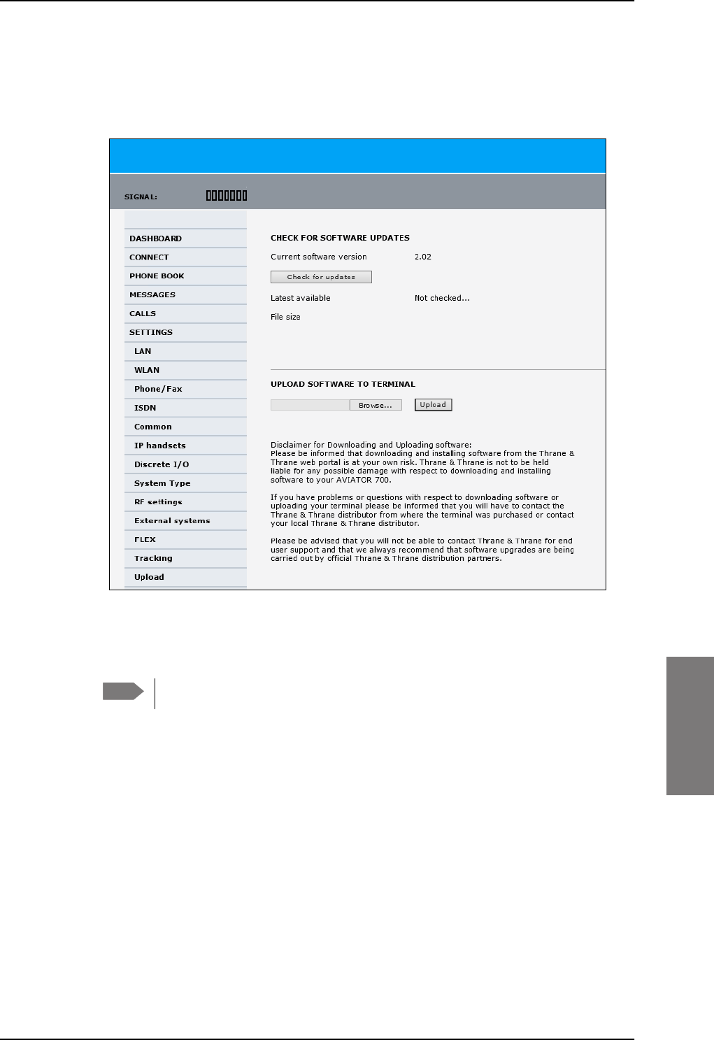
Software update
98-127093-H Chapter 7: Maintenance and troubleshooting 7-7
7777
Updating the software
1. In the web interface of the SBU, select SETTINGS from the left navigation pane.
2. Click Upload from the left navigation pane.
Figure 7-3: Web interface: Settings, Upload
3. The Current software version field shows the current software version.
4. To automatically find new software available click Check for updates.
This works from software 1.06 (Level D) and 2.01 (Level E).
or click Browse...
5. Browse to the new software version and accept it.
6. Click the Upload button.
Note that the upload procedure takes a couple of minutes. When done, the SBU
automatically restarts with the new software version.
If software upload fails - how to recover
To recover from a failed software upload, turn off the SBU and turn it on again. Then repeat
the upload procedure as described in Updating the software on page 7-7.
If software upload still fails, use the IP Reset button as described in IP Reset (Default)
button on page 7-14 to initiate a software upload from an external server.
Note
SB-Lite.book Page 7 Tuesday, September 5, 2017 1:38 PM
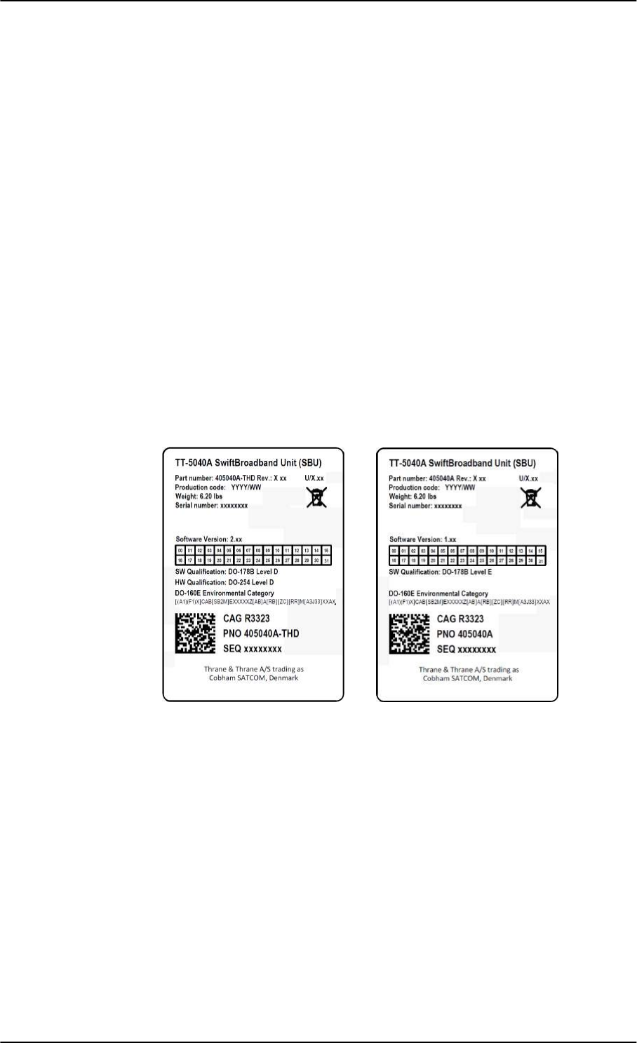
Software update
7-8 Chapter 7: Maintenance and troubleshooting 98-127093-H
7.3.2 Verify the software update
Test procedure
1. The SBU software version can be viewed in the DASHBOARD window of the web
interface.
2. After completing the software update procedure, the SBU will perform a POST (Power
On Self Test).
3. When the POST has finished, the green Fail/Pass LED on the front of the SBU must
become steadily green. Verify that the Fail/Pass LED is not red nor flashing orange once
every 2 seconds. Wait until the Fail/Pass LED is green.
4. Verify that the software update has been completed successfully. You find the software
version number in the DASHBOARD window of the web interface.
Software identification procedure
On the PartNumber / SerialNumber identification label on the SBU make a cross mark in the
Software Ver. field number according to the new software version.
Figure 7-4: Software identification on the SBU label, Level D and Level E
SB-Lite.book Page 8 Tuesday, September 5, 2017 1:38 PM
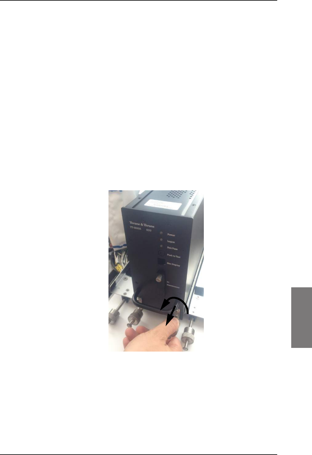
To exchange LRUs
98-127093-H Chapter 7: Maintenance and troubleshooting 7-9
7777
7.4 To exchange LRUs
This document describes the procedures for removal and re-installation of an
AVIATOR 200/300/350 LRU:
• SBU (405040A-THD).
7.4.1 Time consumption
The time consumption for removal and re-installation of an LRU is estimated to 15 minutes.
7.4.2 Tools
No tools required.
7.4.3 Removal and re-installation of the SBU
1. Ensure that power is removed from the satcom system before removing any LRU!
2. Pull and turn to loosen the knurled knob(s) that retain(s) the LRU in the tray.
Figure 7-5: Exchanging an LRU (example)
SB-Lite.book Page 9 Tuesday, September 5, 2017 1:38 PM
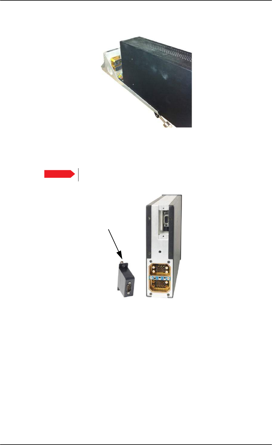
To exchange LRUs
7-10 Chapter 7: Maintenance and troubleshooting 98-127093-H
3. Pull the LRU straight out from the tray by the handle. Be careful not to drop the unit.
Figure 7-6: Pull out the LRU
4. If the LRU has a Configuration Module (CM), unscrew it and pull it out from the rear of
the LRU.
Make sure that the Configuration Module is attached to the airframe.
Figure 7-7: Attach CM to the airframe
Re-installation
Follow the procedure above in reverse order. Make sure that the LRU is completely seated
against the mating A404 connector.
Important
Pull straight out!
Attach to
the airframe!
SB-Lite.book Page 10 Tuesday, September 5, 2017 1:38 PM

Troubleshooting
98-127093-H Chapter 7: Maintenance and troubleshooting 7-11
7777
7.5 Troubleshooting
7.5.1 Status signalling
Built-In Test Equipment
The SBU provides a Built-In Test Equipment (BITE) function in order to make fault
diagnostics easy during service and installation.
The BITE test is performed during:
• Power On Self Test (POST), which is automatically performed each time the system is
powered on.
• Person Activated Self Test (PAST), which is initiated by pushing the Push To Test button
on the SBU front panel.
Also, during operation a Continuous Monitoring BITE function is performed.
Details on error messages after a POST or PAST for the SBU can be found in the event list of
the SBU, see View the Event list, Event log and extended status on page 7-16.
Means of signalling
The AVIATOR 200/300/350 system provides various methods for signalling the status of
the system.
•LEDs on the front panel of the SBU are used to signal:
• Power on/off
• Logon
• Fail/Pass
• The built-in web interface of the SBU shows any BITE error codes with a short message
describing each error.
Push to Test button on SBU
The SBU has a hardware reset/test button placed on the front panel for BITE purposes. Use
the button on the SBU to activate a self test (PAST).
SB-Lite.book Page 11 Tuesday, September 5, 2017 1:38 PM
Troubleshooting
7-12 Chapter 7: Maintenance and troubleshooting 98-127093-H
7.5.2 Status signalling with LEDs
LEDs on SBU
During the power-up procedure all LEDs on the front plate are orange. If all 3 LEDs on the
front stay orange after power up, check that TP8 of the SBU is connected to ground. If the
wiring is good, the SBU software is corrupted. Contact your local distributor for instructions
how to proceed.
Power LED on SBU
Behavior Description
Green Power OK
Orange During upstart procedure
Off No power
Table 7-1: Function of the SBU Power LED
Logon LED on SBU
Behavior Description
Red Acquiring satellite network
Orange Network synchronization
Green Network logon
Off No acquired satellite/logged off
Table 7-2: Function of the SBU Logon LED
Fail/Pass LED on SBU
Behavior Description
Steady red A fault which may degrade the system
operation is present in the SBU
Flashing: short green/ long
pause
Power On Self Test (POST) or Person
Activated Self Test (PAST) in progress
Flashing: long green/ short
orange
No current failure, but a BITE failure /
warning is logged in the error log
Steady green No faults
Table 7-3: Function of the SBU Fail/Pass LED
SB-Lite.book Page 12 Tuesday, September 5, 2017 1:38 PM
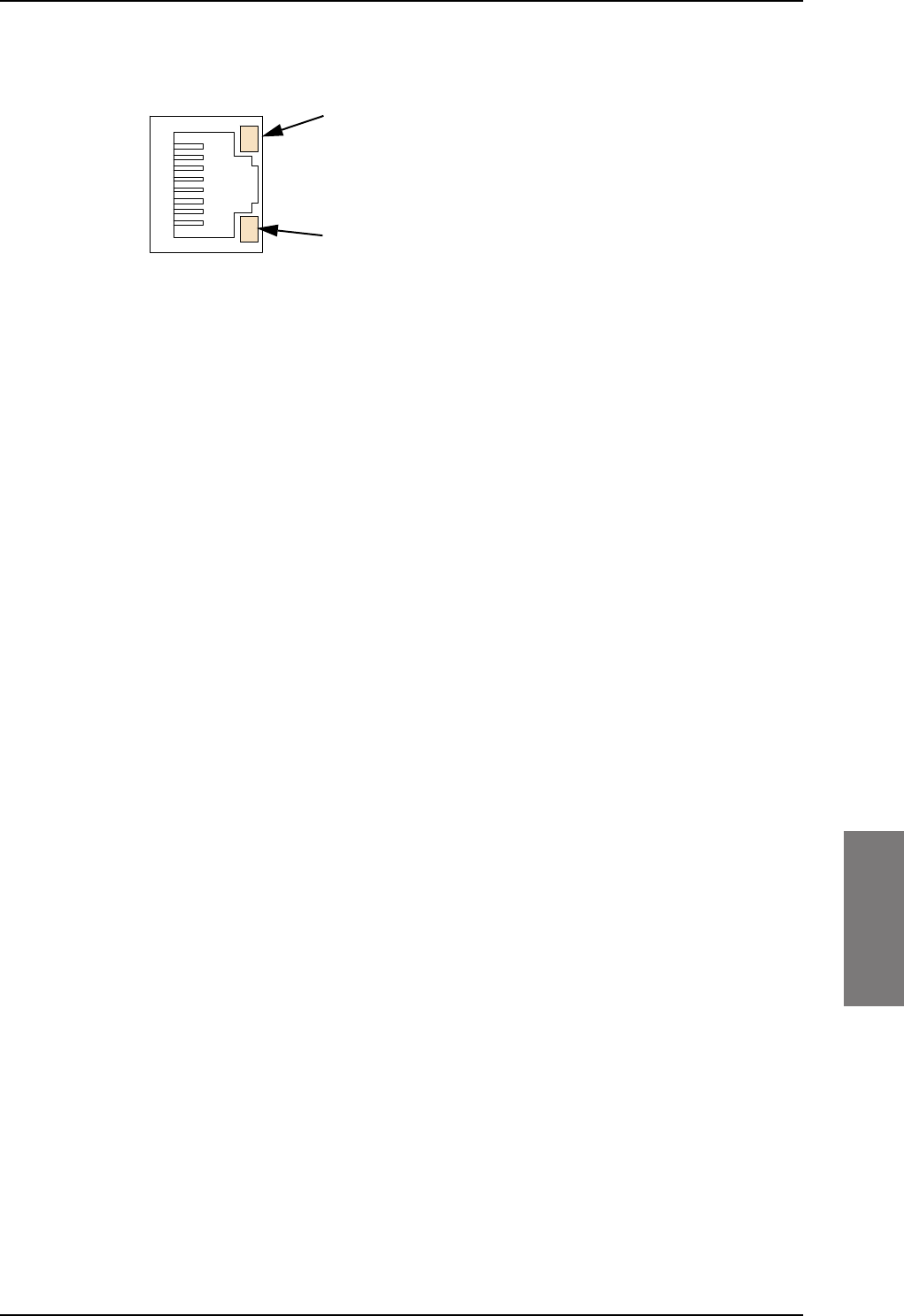
Troubleshooting
98-127093-H Chapter 7: Maintenance and troubleshooting 7-13
7777
LEDs on maintenance connector
Figure 7-8: Function of the LEDs on the front maintenance connector
LED Flashing yellow
Activity (data in/out)
LED Steady green
Link (correct connection)
SB-Lite.book Page 13 Tuesday, September 5, 2017 1:38 PM
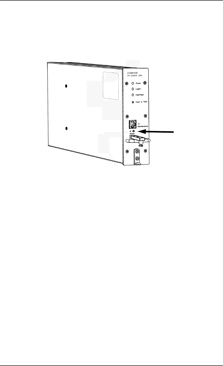
Troubleshooting
7-14 Chapter 7: Maintenance and troubleshooting 98-127093-H
7.5.3 IP Reset (Default) button
The SBU has an IP Reset (Default) button next to the front LAN maintenance connector
below the metal cover. The button has two functions: To reset the terminal’s IP address and
netmask to the default value, 192.168.0.1 and to reset the terminal to factory default
settings.
Figure 7-9: IP Reset (Default) button on SBU front
The table on the next page describes how you can use the IP reset button.
SB-Lite.book Page 14 Tuesday, September 5, 2017 1:38 PM

Troubleshooting
98-127093-H Chapter 7: Maintenance and troubleshooting 7-15
7777
Action Function
With the SBU running,
push the IP Reset
button normally.
Temporary reset to default values: The SBU’s IP address
and IP netmask are temporarily set to the default value (default
IP address: 192.168.0.1, default netmask: 255.255.255.0).
With this function, even if the IP address has been changed and
you do not remember the new IP address, you can still access
the web interface and see your current configuration. The
default value is not saved in the configuration, but is only valid
until next reboot.
With the terminal
running, push and hold
the IP Reset button for
30 seconds, until the
Power indicator on the
SBU front plate flashes
orange.
Reset to factory settings: The SBU restores factory settings
and reboots the system. All settings are reset to factory default,
incl. the IP address of the SBU and the administrator password.
Exception: The settings that are specific for the installation
are not reset. These are the settings on the pages:
• SETTINGS > System Type
• SETTINGS > RF Settings
• SETTINGS > External Systems (including ACARS)
• SETTINGS > Flex
• ADMINISTRATOR > User permission > SMS
While the terminal is
booting, push and hold
the IP Reset button.
For service use only!
This firmware upload procedure is only to be used if the other
procedures fail due to missing or corrupted firmware. This
setup uploads software to the SBU from a TFTP server via the
LAN connection. The procedure is as follows:
1. Activate or install a TFTP server on a PC.
2. Locate the correct software image (xxx.dl) for the SBU and
place it in the TFTP server directory.
3. Rename the image to ttexp.dl.
4. Reconfigure the PC LAN interface to use the static address
192.168.0.2/255.255.255.0.
5. Power off the SBU.
6. Connect the PC LAN Interface to the SBU,
7. Push and hold down the Reset button.
8. Keep the Reset button pushed while powering on the SBU,
and through the next step.
9. Monitor the TFTP server window. When the upload starts
you can release the Reset button.
10. When the TFTP upload finishes the SBU boots up using the
new image.
Table 7-4: How to reset the IP address or the terminal software to default settings
SB-Lite.book Page 15 Tuesday, September 5, 2017 1:38 PM
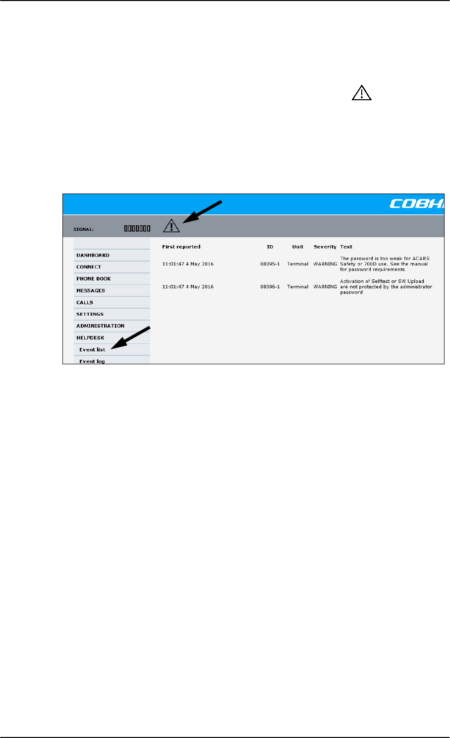
Troubleshooting
7-16 Chapter 7: Maintenance and troubleshooting 98-127093-H
7.5.4 View the Event list, Event log and extended status
Overview
When an event is registered, the web interface shows an event icon in the icon bar as
long as the event is active. The Event list only shows events that are currently active,
whereas the Event log shows the history of events that have occurred.
Event list
To view the event list, click the event icon from the icon bar at the top of the web interface,
or select HELPDESK > Event list from the left navigation pane.
Figure 7-10: Web interface: Help desk, Event list
The Event list page shows a detailed list of active events including the time of the first
occurrence, ID and severity of the event message, and a short text describing the error. For
a list of events with description, ID, explanation and remedy see List of events on page C-2.
Event log
The Event log shows the same information as the Event list, but also includes events that
occurred in the past and are no longer active. Additionally, it lists events of informational
character, describing normal phases of operation for the SBU. The event log holds
information of events registered in the SBU or antenna. The same events are also indicated
in the Antenna and Terminal LEDs on the SBU LED panel. The log includes the time of the
occurrence, a short description, location of the error etc. This information can help
troubleshooting errors in the system. You can see the event log in the web interface.
To view the Event log, select HELPDESK > Event log from the left navigation pane.
Extended status
The Extended Status page shows the following information:
• The antenna Product ID.
• The status of the connection to the air interface (IAI-2). This field should normally show
“Registered”, unless the system is still in the startup process.
• Ongoing data sessions (IP address) and connection status, e.g. Active or Suspended.
SB-Lite.book Page 16 Tuesday, September 5, 2017 1:38 PM
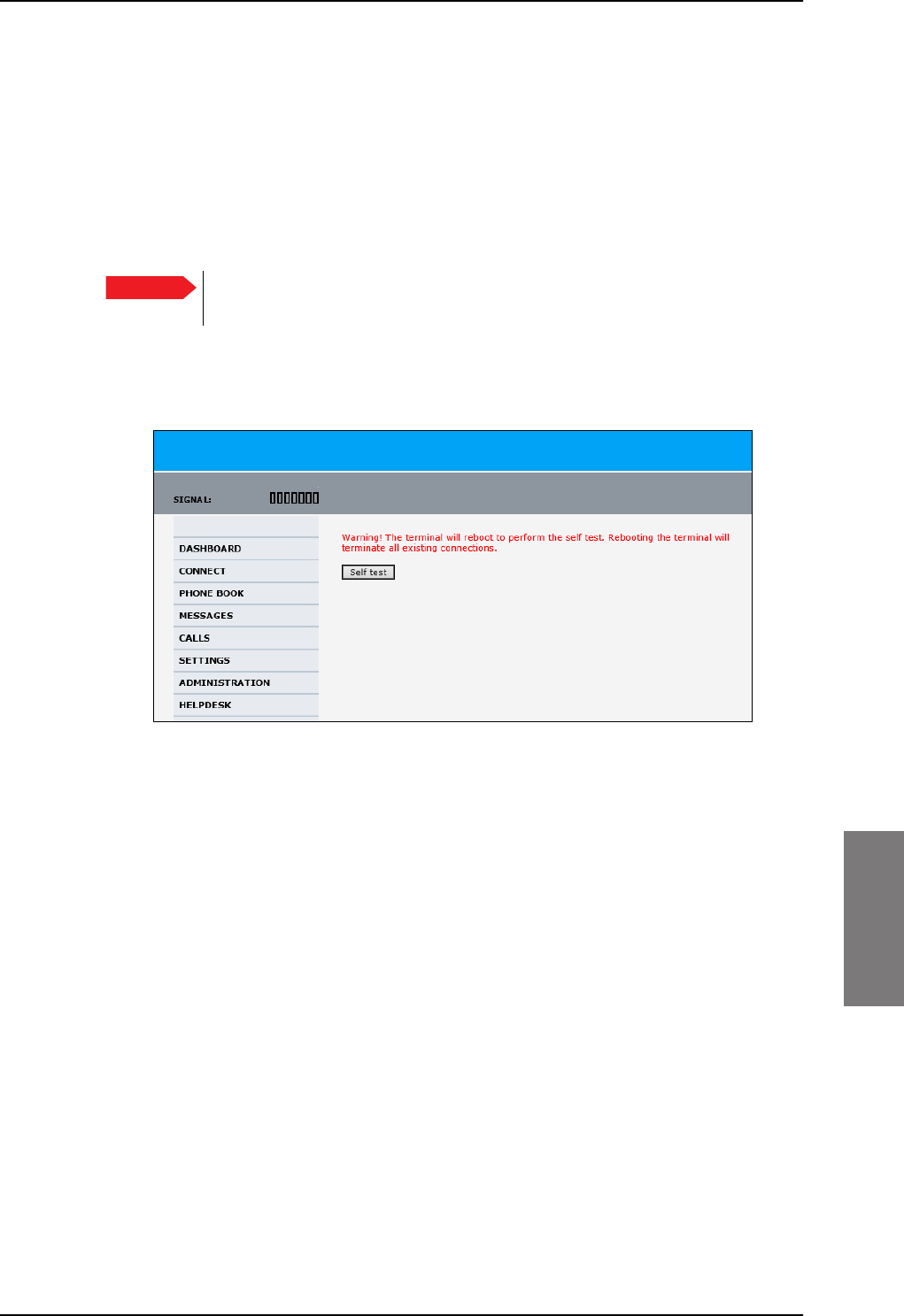
Troubleshooting
98-127093-H Chapter 7: Maintenance and troubleshooting 7-17
7777
• Ongoing calls and their connection status.
To update the information on the Extended status page, click Refresh.
7.5.5 Self test
The Self test performs system test on the AVIATOR 200/300/350 system, similar to the
tests that are performed during the Power On Self Test (POST).
To activate a Self test, do as follows:
1. Select HELPDESK > Self test.
Figure 7-11: Web interface: Help desk, Self test
2. Click Self test.
3. Click OK in the Warning dialog.
The SBU now performs a self test and resets the SBU.
Important The SBU will reboot when performing the self test. All ongoing calls or data
sessions will be terminated.
SB-Lite.book Page 17 Tuesday, September 5, 2017 1:38 PM

Troubleshooting
7-18 Chapter 7: Maintenance and troubleshooting 98-127093-H
7.5.6 Initial troubleshooting
This section describes an initial check of the primary functions of the
AVIATOR
200/300/350 system.
Means available for troubleshooting
The following means are available for troubleshooting:
•LEDs. Generally, if a fault occurs without any obvious reason, it is always recommended
to observe the LEDs. For information on the LEDs, refer to Status signalling on page 7-
11.
•Web interface. For troubleshooting errors in the SBU, you may connect to the front
LAN interface on the SBU and use the web interface to inspect any alarm messages.
For information on the web interface refer to Tool for setup and use: Built-in web
interface on page 6-6.
•Diagnostic report. You can generate a diagnostic report that can be used for
troubleshooting errors in the AVIATOR
200/300/350 system. To generate the diagnostic
report, access the web interface and select HELPDESK. then click Generate report.
Save the report on your PC.
• Enclose the diagnostic report and the service log when requesting support.
Problem What to do
No connection to the
SBU maintenance
connector
Depending on the options in your system you might experience
limitations when using an Ethernet interface of the
AVIATOR 200/300/350. For systems without the built-in router
option enabled, i.e. the basic version or the version with Wireless
option, note the following limitation:
• To use the SBU Maintenance connector disconnect or switch
off any PC connected to another LAN interface of the SBU.
No GPS signal:
Interference from
satcom antenna on
GPS antenna
If the existing GPS antenna on board the aircraft does not provide
sufficient filtering of the satcom antenna signal to provide a
usable GPS signal, you must replace the existing GPS antenna with
a GPS antenna that has a satcom filter.
Registration for voice
or data not possible
In case the system cannot register properly for voice or data
service, check with your Service provider that the SIM card in the
Configuration module of the SBU is not blocked.
Table 7-5: Initial troubleshooting
SB-Lite.book Page 18 Tuesday, September 5, 2017 1:38 PM

Return units for repair
98-127093-H Chapter 7: Maintenance and troubleshooting 7-19
7777
7.6 Return units for repair
Should your Cobham SATCOM product fail, please contact your dealer or installer, or the
nearest Cobham SATCOM partner. You will find the partner details on
www.cobham.com/satcom, Technical Service Partner List. You can also access the
Partner Portal at www.cobham.com/satcom, Cobham SYNC Partner Portal, which may
help you solve the problem. Your dealer, installer or Cobham SATCOM partner will assist
you whether the need is user training, technical support, arranging on-site repair or sending
the product for repair. Your dealer, installer or Cobham SATCOM partner will also take care
of any warranty issue.
Repackaging requirements
Should you need to send the product for repair, please read the below information before
packing the product.
The shipping carton has been carefully designed to protect the AVIATOR 200/300/350 and
its accessories during shipment. This carton and its associated packing material should be
used when repacking for shipment. Attach a tag indicating the type of service required,
return address, part number and full serial number. Mark the carton FRAGILE to ensure
careful handling.
Correct shipment is the customer’s own responsibility.
If the original shipping carton is not available, the following general instructions should be
used for repacking with commercially available material.
1. Wrap the defective unit in heavy paper or plastic. Attach a tag indicating the type of
service required, return address, part number and full serial number.
2. Use a strong shipping container, e.g. a double walled carton.
3. Protect the front- and rear panel with cardboard and insert a layer of shock-absorbing
material between all surfaces of the equipment and the sides of the container.
4. Seal the shipping container securely.
5. Mark the shipping container FRAGILE to ensure careful handling.
Failure to do so may invalidate the warranty.
Note
SB-Lite.book Page 19 Tuesday, September 5, 2017 1:38 PM

Disposal of electrical and electronic equipment
7-20 Chapter 7: Maintenance and troubleshooting 98-127093-H
7.7 Disposal of electrical and electronic equipment
Old electrical and electronic equipment marked with this symbol can contain
substances hazardous to human beings and the environment. Never dispose
these items together with unsorted municipal waste (household waste). In
order to protect the environment and ensure the correct recycling of old
equipment as well as the re-utilization of individual components, use either public
collection or private collection by the local distributor of old electrical and electronic
equipment marked with this symbol.
Contact the local distributor for information about what type of return system to use.
SB-Lite.book Page 20 Tuesday, September 5, 2017 1:38 PM
Appendices
SB-Lite.book Page 1 Tuesday, September 5, 2017 1:38 PM
SB-Lite.book Page 2 Tuesday, September 5, 2017 1:38 PM

98-127093-H A-1
Appendix A
AAAA
Equipment specifications A
A.1 Introduction
Important note!
The information, drawings, and wiring diagrams contained in this manual are intended as a
reference for engineering planning only. It is the installer’s responsibility to compose
installation drawings specific to the aircraft.
For specifications of the antenna please see the documentation provided with the antenna.
For equipment drawings of the AVIATOR Wireless Handset and Cradle see
AVIATOR Wireless Handset and Cradle Installation & Maintenance Manual
(98-129600).
Note Cables and connectors are not included.
Note
SB-Lite.book Page 1 Tuesday, September 5, 2017 1:38 PM

AVIATOR 200/300/350 system components
A-2 Appendix A: Equipment specifications 98-127093-H
A.2 AVIATOR 200/300/350 system components
A.2.1 TT-5040A SwiftBroadband Unit (SBU)
Characteristics Specification
Dimensions
(L x W x H)
ARINC 404A 1/4 ATR short
320.5 mm x 193.5 mm x 57.15 mm (12.62” x 7.62” x 2.25”)
Weight 2.8 kg ±0.1 kg (6.2 lbs ±0.22 lbs) including TT-5040-001 CM
Mounting Mount in an ARINC 404A 1/4 ATR short tray in a temperature controlled
location.
Forced cooling is not required and not recommended.
Supply Voltage
Power Hold-up
Nominal: +28.0 V DC
Voltage range,
continuous operation: +20.5 V DC to 32.2 V DC
short time operation: +18.0 V DC to 32.2 V DC
200 ms. Fully operational: 5 ms.
Typical Power
Consumption (idle) (SBU,
CM, HLD & satcom
antenna)
30 W
Total Maximum Power
Consumption (SBU, CM,
HLD and satcom antenna)
See examples:
With LGA-3000 (LGA, RF + GPS): Max. 84 W
With TT-3002A (LGA, RF only): Max. 83 W
With TT-5006A (IGA, Coax Modem): Max. 98 W
With AMT-50, HGA-6000 (HGA, ARINC-781): Max. 83 W
With HGA-7000 (HGA, Coax Modem): Max. 107 W
Maximum Heat Dissipation
(SBU & CM)
<33 W
Connectors Rear: ARINC 404A
Front: RJ45 Female.
Operating Temperature
Ground Survival
Temperature
Shelf life
-25 °C to +55 °C
-55 °C to +85 °C
7 years at 35°C in original packing
Table A-1: Equipment specifications for TT-5040A SBU
SB-Lite.book Page 2 Tuesday, September 5, 2017 1:38 PM
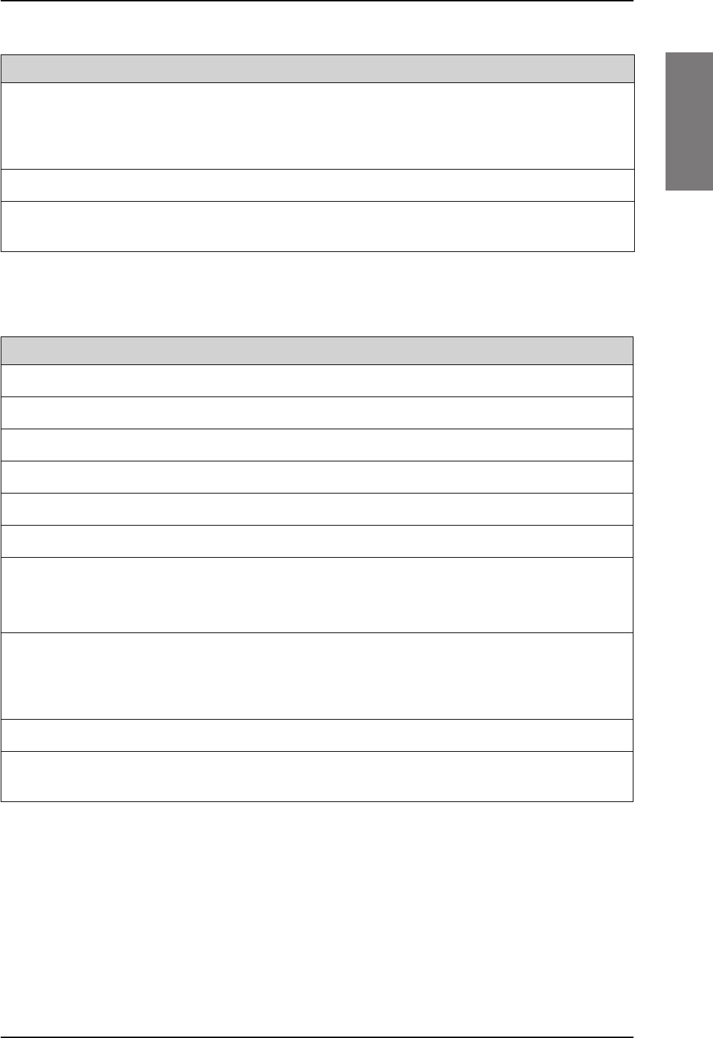
AVIATOR 200/300/350 system components
98-127093-H Appendix A: Equipment specifications A-3
AAAA
A.2.2 TT-5040A-001 Configuration Module (CM) for SBU
Altitude Non pressurized (Cat. F1): 55,000 ft
Pressurized (Cat. A1): 15,000 ft
Decompression (Cat. A1): 55,000 ft
Overpressure (Cat. A1): -15,000 ft
Relative humidity 95% non-condensing at +50°C
Environmental Categories Refer to Environmental Qualification form in SwiftBroadband unit (SBU)
on page B-2 in Appendix B.
Characteristics Specification
Table A-1: Equipment specifications for TT-5040A SBU (Continued)
Characteristics Specification
Dimensions (L x W x H) 47 mm x 45.5 mm x 20.0 mm (1.85” x 1.79” x 0.79”)
Weight 0.07 kg ±0.01 kg (0.15 lbs ±0.02 lbs)
Mounting The CM is inserted in the TT-5040A SBU
Supply Voltage The CM is powered by the SBU.
Heat dissipation Included in TT-5040A SBU
Connector 9-pin Sub-D connector
Operating Temperature
Ground Survival
Temperature
-25 C to +55 C
-55 C to +85 C
Altitude Non pressurized (Cat. F1): 55,000 ft
Pressurized (Cat. A1): 15,000 ft
Decompression (Cat. A1): 55,000 ft
Overpressure (Cat. A1): -15,000 ft
Relative humidity 95% non-condensing at +50°C
Environmental Categories Refer to Environmental Qualification form in SwiftBroadband unit (SBU)
on page B-2 in Appendix B.
Table A-2: Equipment specifications for TT-5040A-001 CM
SB-Lite.book Page 3 Tuesday, September 5, 2017 1:38 PM

AVIATOR 200/300/350 system components
A-4 Appendix A: Equipment specifications 98-127093-H
A.2.3 TT-5016A High Power Amp./Low Noise Amplifier/Diplexer
(HLD)
Characteristics Specification
Dimensions (L x W x H) 228.0 mm x 200.0 mm x 50.0 mm (8.98” x 7.87” x 1.97”)
Weight 2.6 kg ±0.1 kg (5.7 lbs ±0.22 lbs)
Mounting Can be installed in a non-temperature controlled location.
Forced cooling is not required.
Should be mounted as close to the Antenna unit as possible for minimum
cable loss.
Place the HLD with sufficient contact to the surface, respecting the max.
resistance of 25 m. The HLD can be mounted on a shelf or directly on
the fuselage.
Supply Voltage The HLD is powered by the SBU.
Heat dissipation < 40 W
Connectors Tx input: N-female
Rx output: TNC-female
Satcom antenna: TNC-female
Ground stud
Operating Temperature
Ground Survival
Temperature
-55 C to +70 C
-55 C to +85 C
Altitude Non pressurized (Cat. F1): 55,000 ft
Pressurized (Cat. A1): 15,000 ft
Decompression (Cat. A1): 55,000 ft
Overpressure (Cat. A1): -15,000 ft
Relative humidity 95% non-condensing at +50°C
Environmental Categories Refer to Environmental Qualification form in High Power Amplifier/Low
Noise Amplifier/Diplexer (HLD) on page B-4 in Appendix B.
Table A-3: Equipment specifications for TT-5016A HLD
SB-Lite.book Page 4 Tuesday, September 5, 2017 1:38 PM
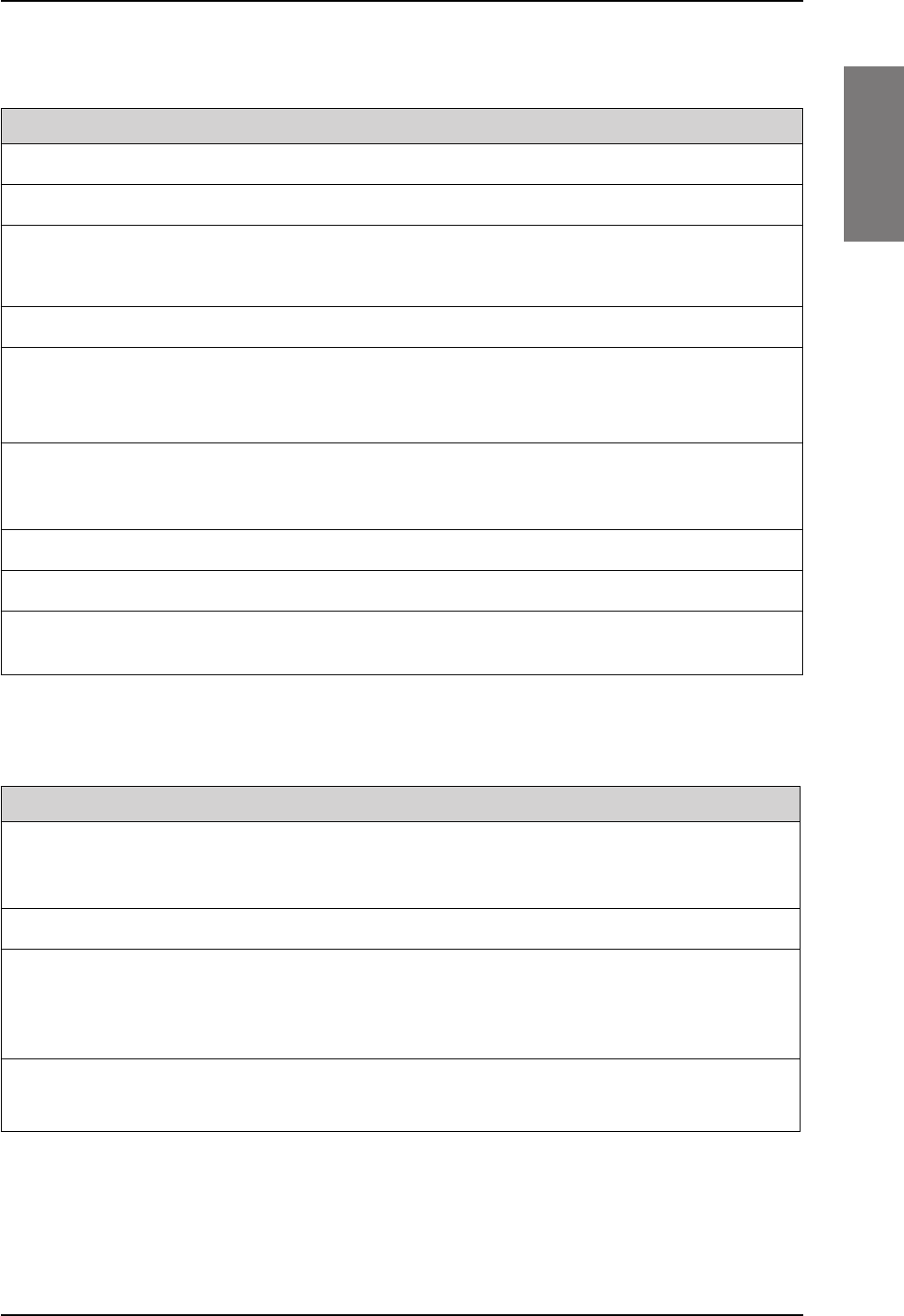
AVIATOR 200/300/350 system components
98-127093-H Appendix A: Equipment specifications A-5
AAAA
A.2.4 TT-5040A-004 WLAN antenna
A.2.5 TT-5038A-003 Rx Power Splitter
Characteristics Specification
Dimensions (L x W x H) 12 mm x 119 mm x 13 mm (0.48” x 4.7” x 0.5”)
Weight 28.3 g (1 ounce)
Mounting For mounting instructions for WLAN antennas see Figure 5-
2: Mounting two WLAN antennas for optimum performance in
TT-5040A-004 WLAN antennas on page 5-7.
Connector Male TNC
Operating Temperature
Ground Survival
Temperature
-40 C to +71 C
-55 C to +85 C
Altitude Pressurized (Cat. A1): 15,000 ft
Decompression (Cat. A1): 45,000 ft
Overpressure (Cat. A1): -15,000 ft
Relative humidity 95% non-condensing at +50°C
Cable type Plenum, RG-316U coaxial
Cable length (including
connector)
7.5” ± 0.25” (190.5 ±6.4 mm)
Table A-4: Equipment specifications for WLAN antenna
Characteristics Specification
Dimensions
(L x W x H)
86.8 mm x 50.8 mm x 19.1 mm
(3.42” x 2.00” x 0.75”)
including connectors.
Weight 146 g ±10 g (0.32 lbs ±0.02 lbs)
Mounting If the Rx Power Splitter is to be mounted on a flat surface, mount it on a 3
mm mounting plate to provide enough space for mounting of the
connectors.
Can be mounted in an unpressurized but temperature controlled location.
Connectors 3 x N-connector, Female.
Built-in DC-block on the HSU (SBU) port.
Table A-5: General specifications for Rx Power Splitter
SB-Lite.book Page 5 Tuesday, September 5, 2017 1:38 PM

AVIATOR 200/300/350 system components
A-6 Appendix A: Equipment specifications 98-127093-H
Operating Temperature
Ground Survival
Temperature
-25 C to +55 C
-55 C to +85 C
Altitude 55000 ft
Environmental Categories Refer to Environmental Qualification form in Rx Power Splitter on
page B-6 in Appendix B.
Characteristics Specification
Table A-5: General specifications for Rx Power Splitter
SB-Lite.book Page 6 Tuesday, September 5, 2017 1:38 PM
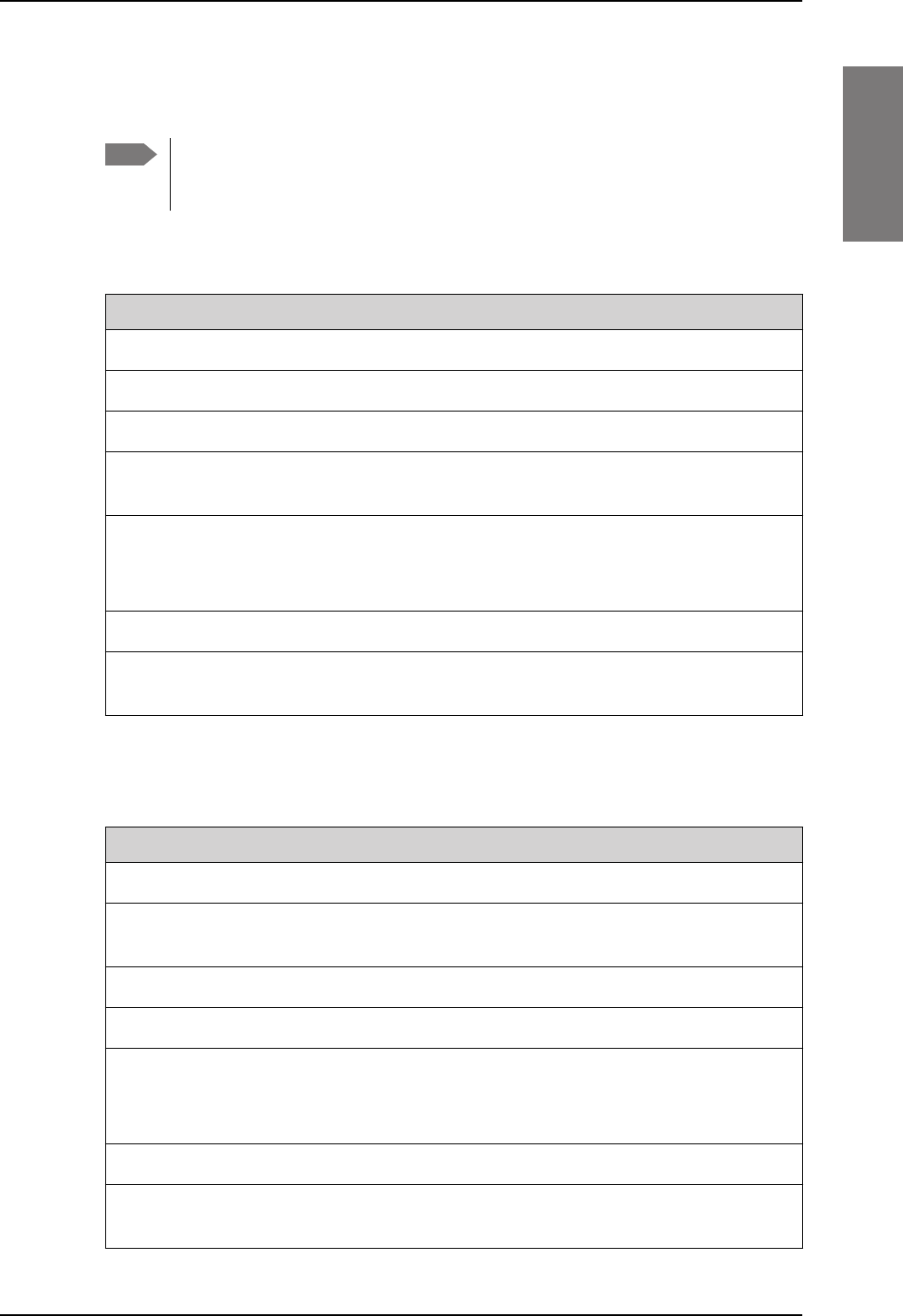
AVIATOR 200/300/350 handsets and cradles
98-127093-H Appendix A: Equipment specifications A-7
AAAA
A.3 AVIATOR 200/300/350 handsets and cradles
A.3.1 TT-5621B 2-Wire Handset
A.3.2 TT-5622B 2-Wire Cradle
Note For specifications of the AVIATOR Wireless Handset see AVIATOR Wireless
Handset and Cradle Installation & Maintenance Manual (part number: 98-
129600)
Characteristics Specification
Dimensions (L x W x H) 200.0 mm x 52.0 mm x 31.5 mm (7.87” x 2.05” x 1.24”)
Weight 0.22 kg ±50 g (0.49 lbs ±0.11 lbs) incl. cable.
Mounting Mount in a pressurized and temperature controlled location.
Power consumption Max. 750 mW for handset and cradle (included in SBU
power consumption).
Operating Temperature
Ground Survival
Temperature
-25 C to +55 C
-40 C to +80 C
Altitude 55,000 ft
Environmental Categories Refer to Environmental Qualification form in 2-Wire
Handset and 2-Wire Cradle on page B-8 in Appendix B.
Table A-6: Equipment specifications for 2-Wire Handset
Characteristics Specification
Dimensions (L x W x H) 160.5 mm x 61.0 mm x 28.4 mm (6.30” x 2.40” x 1.12”)
Weight 0.20 kg ±50 g (0.43 lbs ±0.11 lbs)
incl. connector cable.
Mounting Mount in a pressurized and temperature controlled location.
Power consumption See TT-5621B 2-Wire Handset on page A-7.
Operating Temperature
Ground Survival
Temperature
-25 C to +55 C
-40 C to +80 C
Altitude 55,000 ft
Environmental Categories Refer to Environmental Qualification form in 2-Wire
Handset and 2-Wire Cradle on page B-8 in Appendix B.
Table A-7: Equipment specifications for 2-Wire Cradle
SB-Lite.book Page 7 Tuesday, September 5, 2017 1:38 PM

AVIATOR 200/300/350 handsets and cradles
A-8 Appendix A: Equipment specifications 98-127093-H
SB-Lite.book Page 8 Tuesday, September 5, 2017 1:38 PM

98-127093-H B-1
Appendix B
BBBB
DO-160 specifications B
B.1 General
B.1.1 Certifying agency
Approval of the installation of the AVIATOR 200/300/350 system is not authorized by this
installation manual. Acceptance for the installation and use of the AVIATOR
200/300/350
system and its associated components must be obtained through the appropriate offices of
the FAA or other certifying agency. It is recommended that all proposed installations be
coordinated with the local jurisdiction of the FAA or other certifying agency prior to
performing the installation.
B.1.2 Environmental Qualification Forms
The Environmental Qualification Forms list the environmental categories under which all
Cobham SATCOM components of the AVIATOR
200/300/350 system are approved.
Please refer to RTCA DO-160D/E for further details on the following Environmental
Qualification Forms.
SB-Lite.book Page 1 Tuesday, September 5, 2017 1:38 PM

AVIATOR 200/300/350 system components
B-2 Appendix B: DO-160 specifications 98-127093-H
B.2 AVIATOR 200/300/350 system components
B.2.1 SwiftBroadband unit (SBU)
Part Number: 405040A (AVIATOR 200/300/350) or 405040A-THD
(AVIATOR
200D/300D/350D)
DO-160E string: [(A1)(F1)X]CAB[SB2M]ExxxxxZ[AB]A[RB][ZC][RR]M[A3J33]XXAX
Conditions DO-160E Cat. Comments
Temperature and Altitude 4.0 A1, F1 Installation in temperature controlled areas
and inside or outside pressurized locations.
Low Temperature 4.5.1 & 4.5.2 Short time operating low is -40°C. Unit is
active, but inoperable until the unit
temperature is > -30°C.
Min. operational temperature is -25°C.
High Temperature 4.5.3 & 4.5.4 Short time operating high (30 min.): +70°C
Max. operating high temperature is +55°C
In-Flight Loss of Cooling 4.5.5 X Forced cooling is not required and not
recommended.
Altitude 4.6.1 Max. altitude: 55000 ft
Decompression 4.6.2 Decompression test at 55000 ft
Overpressure 4.6.3 Overpressure at -15000 ft
Temperature Variation 5.0 C Installation within temperature controlled
areas: 2°C/min.
Humidity 6.0 A Standard Humidity: 95% relative humidity
at 38°C to 50°C for 48 hours.
Installation within environmentally
controlled zones
Operational Shocks and Crash
Safety
7.0 B Equipment tested to: Standard operational
shock and crash safety.
Vibration 8.0 S, B2,
M
Equipment tested without shock mounts to
Category S, Curve B2 and Curve M.
Explosion Proofness 9.0 E Not hermetically sealed equipment
Waterproofness 10.0 X No test required
Fluids Susceptibility 11.0 X No test required
Table B-1: Environmental Qualification Form for SBU
SB-Lite.book Page 2 Tuesday, September 5, 2017 1:38 PM
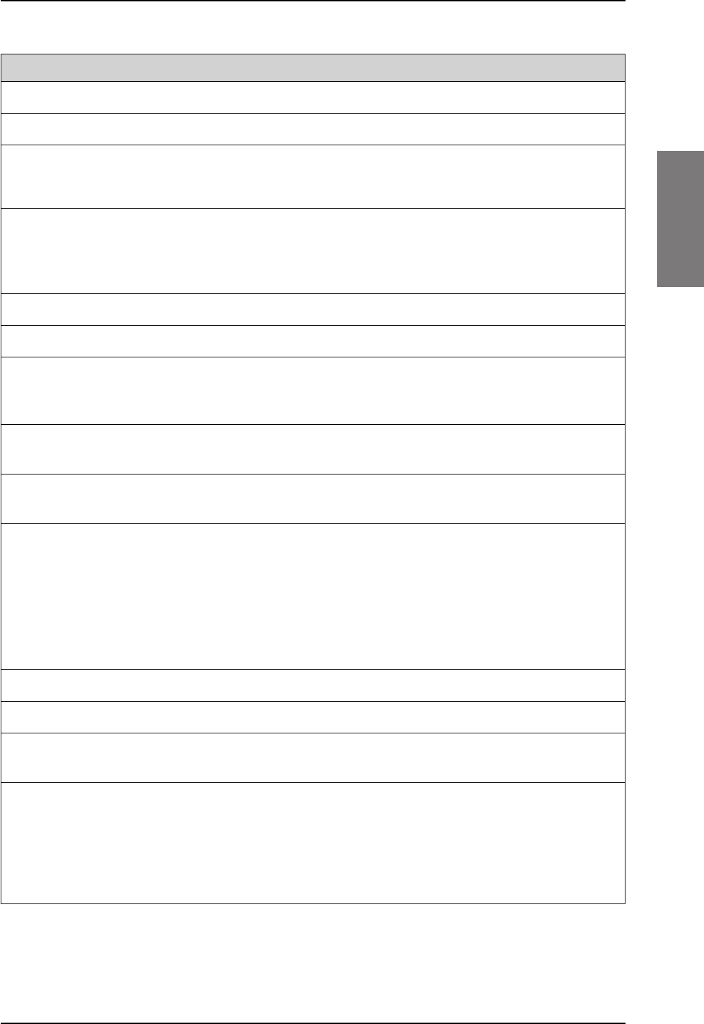
AVIATOR 200/300/350 system components
98-127093-H Appendix B: DO-160 specifications B-3
BBBB
Sand and Dust 12.0 X No test required
Fungus Resistance 13.0 X No test required
Salt Spray 14.0 X No test required
Magnetic Effect 15.0 Z Magnetic deflection distance: < 0.3 m
Power Input 16.0 AB Power supply: +28 V DC.
Reconnection of voice and data calls is not
required, if a power interrupt less than 200
ms occurs during transfer of power sources.
Voltage Spike 17.0 A Power supply: +28 V DC.
Audio Susceptibility 18.0 RB Power supply: +28 V DC.
Induced Susceptibility 19.0 ZC Equipment intended for operation in
systems where interference-free operation
is required.
Radio Frequency Susceptibility 20.0 RR High Intensity Radiated Field (HIRF)
associated with normal environment.
Emission of Radio Frequency
Energy
21.0 M Installation in areas with significant
electromagnetic apertures.
Lightning Induced Transient
Susceptibility
22.0 A3J33 Equipment and wiring in moderately
exposed environment in an all metal
airframe.
The Configuration Module is an integrated
part of the SBU, and so the pin injection
tests are not required for the Configuration
Module interface.
Lightning Direct Effects 23.0 X No test required
Icing 24.0 X No test required
Electrostatic Discharge ESD 25.0 A Operation, installation and repair in an
aerospace environment.
Fire, Flammability 26.0 X Equipment is tested according to FAR 25
Airworthiness Standards: Transport
Category Airplanes, Paragraph 25.853(a)
and Appendix F - Part I (a)(1)(ii) and
Paragraph 25.869(a)(4) and Appendix F -
Part I (a)(3).
Conditions DO-160E Cat. Comments
Table B-1: Environmental Qualification Form for SBU (Continued)
SB-Lite.book Page 3 Tuesday, September 5, 2017 1:38 PM

AVIATOR 200/300/350 system components
B-4 Appendix B: DO-160 specifications 98-127093-H
B.2.2 Configuration Module (CM) for SBU
Part Number: 405040A-001
DO-160E string: Please refer to the section SwiftBroadband unit (SBU) on page B-2, as the
Configuration Module is an integral part of the SBU during normal operation and tests.
However, the section 25 Category A test is performed on the Configuration Module as an
individual LRU.
B.2.3 High Power Amplifier/Low Noise Amplifier/Diplexer (HLD)
Part Number: 405016A (AVIATOR 200/300/350) + 405016A-THD
(AVIATOR
200D/300D/350D)
DO-160E string: [(A2)(F2)X]BBB[SCL]E[(Y)(W)]XXFXZXXX[ZC][RR]M[A3J33]XXAX
Conditions DO-160E Cat. Comments
Temperature and Altitude 4.0 A2, F2 Installation in non-temperature controlled
locations and inside or outside pressurized
locations.
Low Temperature 4.5.1 & 4.5.2 Min. operational temperature is -55°C.
Short time operating low is -55°C.
High Temperature 4.5.3 & 4.5.4 Max. operating high temperature: +70°C
Short time operating high: +70°C
In-Flight Loss of Cooling 4.5.5 X Forced cooling is not required and not
recommended.
Altitude 4.6.1 Max. altitude: 55000 ft.
Decompression 4.6.2 Decompression at 55000 ft.
Overpressure 4.6.3 Overpressure at -15000ft.
Temperature Variation 5.0 B Installation in a non-temperature-
controlled or partially temperature
controlled internal section of the aircraft.
Humidity 6.0 B Severe Humidity: 95% relative humidity at
38°C to 65°C for 240 hours.
Installation within environmentally
controlled zones.
Operational Shocks and Crash
Safety
7.0 B Equipment tested to: Standard operational
shocks and crash safety.
Vibration 8.0 SCL Fixed wing turbojet & turboprop/fuselage
zone: Category S, Curve C & L.
Table B-2: Environmental Qualification Form for HLD
SB-Lite.book Page 4 Tuesday, September 5, 2017 1:38 PM

AVIATOR 200/300/350 system components
98-127093-H Appendix B: DO-160 specifications B-5
BBBB
Explosion Proofness 9.0 E Not hermetically sealed equipment.
Waterproofness 10.0 Y, W Tested to condensing and dripping water.
Fluids Susceptibility 11.0 X No test required.
Sand and Dust 12.0 X No test required.
Fungus Resistance 13.0 F Equipment tested to Category F.
Salt Spray 14.0 X No test required.
Magnetic Effect 15.0 Z Magnetic deflection distance: < 0.3 m.
Power Input 16.0 X No test required (power from SBU).
Voltage Spike 17.0 X No test required (power from SBU).
Audio Frequency
Conducted Susceptibility -
Power Inputs
18.0 X No test required (power from SBU).
Induced Signal Susceptibility 19.0 ZC Equipment intended for operation in
systems where interference-free
operation is required.
Radio Frequency Susceptibility 20.0 RR High Intensity Radiated Field (HIRF)
associated with normal environment.
Emission of Radio Frequency
Energy
21.0 M Installation in areas with significant
electromagnetic apertures.
Lightning Induced Transient
Susceptibility
22.0 A3J33 Equipment and wiring in moderately
exposed environment in an all metal
airframe.
Lightning Direct Effects 23.0 X No test required.
Icing 24.0 X No test required.
Electrostatic Discharge (ESD) 25.0 A Operation, installation and repair in an
aerospace environment.
Fire, Flammability 26.0 X Equipment is tested according to FAR 25
Airworthiness Standards: Transport
Category Airplanes, Paragraph 25.853(a)
and Appendix F - Part I (a)(1)(ii) and
Paragraph 25.869(a)(4) and Appendix F -
Part I (a)(3).
Conditions DO-160E Cat. Comments
Table B-2: Environmental Qualification Form for HLD (Continued)
SB-Lite.book Page 5 Tuesday, September 5, 2017 1:38 PM

AVIATOR 200/300/350 system components
B-6 Appendix B: DO-160 specifications 98-127093-H
B.2.4 Rx Power Splitter
Part Number: 405038A-003
DO-160D string: [(A1)(F1)X]CBB[SCL]EXXXXXZXXXZ[RR]M[A3E3]XXA
RTCA/DO-160D Change Numbers
Change
Number Date of Issue Title Section
Change No. 1 Dec. 14, 2000 Vibration
Radio Frequency Susceptibility
8.0
20.0
Change No. 2 June 12, 2001 Power Input
Audio Frequency Conducted Susceptibility - Power Inputs
16.0
18.0
Table B-3: RTCA/DO-160D Change Numbers, Tx Coupler and Rx Power Splitter
Conditions DO-160D Cat. Comments
Temperature and Altitude 4.0 A1 and
F1
Installation in controlled temperature locations
and inside or outside pressurized locations.
Low Temperature 4.5.1 Min. operating low temperature: -25°C
High Temperature 4.5.2 & 4.5.3 Max. operating high temperature: +55°C
In-Flight Loss of Cooling 4.5.4 X Forced cooling is not recommended.
Altitude 4.6.1 Max. altitude: 55000 ft
Decompression 4.6.2 Decompression at 55000 ft
Overpressure 4.6.3 Overpressure at -15000 ft
Temperature Variation 5.0 C Installation within controlled temperature
locations: 2°/min.
Humidity 6.0 B Severe humidity: 95% relative humidity at 38°C
to 65°C for 240 hours.
Installation within non-environmentally
controlled zones.
Operational Shocks and
Crash Safety
7.0 B Equipment tested to: Standard operational
shocks and crash safety.
Vibration 8.0 SCL Standard sinusoidal and random vibration:
Aircraft type: Fixed wing. Turbojet, turbofan,
reciprocating or turbo propeller engines.
Aircraft zone: Fuselage
Table B-4: Environmental Qualification Form for Tx Coupler and Rx Power Splitter
SB-Lite.book Page 6 Tuesday, September 5, 2017 1:38 PM

AVIATOR 200/300/350 system components
98-127093-H Appendix B: DO-160 specifications B-7
BBBB
Explosion Proofness 9.0 E
Waterproofness 10.0 X No test required
Fluids Susceptibility 11.0 X No test required
Sand and Dust 12.0 X No test required
Fungus Resistance 13.0 X No test required
Salt Spray 14.0 X No test required
Magnetic Effect 15.0 Z Magnetic deflection distance: < 0.3 m
Power Input 16.0 X No test required
Voltage Spike 17.0 X No test required
Audio Frequency
Conducted Susceptibility -
Power Inputs
18.0 X No test required
Induced Signal
Susceptibility
19.0 Z Equipment intended for operation in systems
where interference-free operation is required
Radio Frequency
Susceptibility
20.0 RR High Intensity Radiated Field (HIRF) associated
with normal environment.
Emission of Radio
Frequency Energy
21.0 M
Lightning Induced Transient
Susceptibility
22.0 A3E3 Equipment and wiring in moderately exposed
environment in an all metal airframe.
Lightning Direct Effects 23.0 X No test required
Icing 24.0 X No test required
Electrostatic Discharge
(ESD)
25.0 A Operation, installation and repair in an
aerospace environment.
Conditions DO-160D Cat. Comments
Table B-4: Environmental Qualification Form for Tx Coupler and Rx Power Splitter (Continued)
SB-Lite.book Page 7 Tuesday, September 5, 2017 1:38 PM

AVIATOR 200/300/350 handsets and cradles
B-8 Appendix B: DO-160 specifications 98-127093-H
B.3 AVIATOR 200/300/350 handsets and cradles
B.3.1 2-Wire Handset and 2-Wire Cradle
Part Number: 405621B-THW / 405621B-THR / 405622B-THW / 405622B-THR
DO-160C String: [A1X]CAB[(SMB2)(SM)(UFF1)]XXXXXXAXXXB[RR]M[A2E3]XXA
Note For DO-160 specifications of the AVIATOR Wireless Handset see AVIATOR
Wireless Handset and Cradle Installation & Maintenance Manual (part number:
98-129600)
Conditions DO-160D Cat. Comments
Temperature and Altitude 4.0 A1 Installation in controlled temperature and
pressurized location.
Low Temperature 4.5.1 Min. operating low temperature: -25°C
High Temperature 4.5.2 & 4.5.3 Max. operating high temperature: +55°C
In-Flight Loss of Cooling 4.5.4 X No forced cooling required.
Altitude 4.6.1 Max. altitude: 55000 ft
Decompression 4.6.2 Decompression at 55000 ft
Overpressure 4.6.3 Overpressure test at -15000 ft
Temperature Variation 5.0 C Installation within controlled temperature
locations: 2°/min.
Humidity 6.0 A Standard Humidity: 95% relative humidity at
38°C to 50°C for 48 hours.
Installation within environmentally
controlled zones.
Operational Shocks and Crash
Safety
7.0 B Equipment tested to: Standard operational
shocks and crash safety.
Table B-5: Environmental Qualification Form for 2-Wire Handset and Cradle
SB-Lite.book Page 8 Tuesday, September 5, 2017 1:38 PM

AVIATOR 200/300/350 handsets and cradles
98-127093-H Appendix B: DO-160 specifications B-9
BBBB
Vibration 8.0 S2B2
SM
UFF1
Standard random vibration:
Aircraft type: Fixed wing. Turbojet or
turbofan engines.
Standard sinusoidal vibration:
Aircraft type: Fixed wing. Reciprocating or
turbo propeller engines.
Robust Sine-on-Random vibration:
Aircraft type: Helicopter. Turbojet or
reciprocating engines.
Aircraft zone: Instrument panel, console or
equipment rack.
Explosion Proofness 9.0 X No test required
Waterproofness 10.0 X No test required
Fluids Susceptibility 11.0 X No test required
Sand and Dust 12.0 X No test required
Fungus Resistance 13.0 X No test required
Salt Spray 14.0 X No test required
Magnetic Effect 15.0 A Magnetic deflection distance: 0.3 m to 1 m
Power Input 16.0 X No test required
Voltage Spike 17.0 X No test required
Audio Frequency Conducted
Susceptibility
18.0 X No test required
Induced Signal Susceptibility 19.0 B Installation where interference is controlled
to a tolerable level.
Radio Frequency Susceptibility 20.0 RR High Intensity Radiated Field (HIRF)
associated with normal environment.
Emission of Radio Frequency
Energy
21.0 M
Lightning induced Transient
Susceptibility
22.0 A2E3 Cable bundle test: Equipment and wiring in
moderately exposed environment in an all
metal airframe.
Lightning Direct Effects 23.0 X No test required
Conditions DO-160D Cat. Comments
Table B-5: Environmental Qualification Form for 2-Wire Handset and Cradle (Continued)
SB-Lite.book Page 9 Tuesday, September 5, 2017 1:38 PM

AVIATOR 200/300/350 handsets and cradles
B-10 Appendix B: DO-160 specifications 98-127093-H
Icing 24.0 X No test required
Electrostatic Discharge (ESD) 25.0 A Operation, installation and repair in an
aerospace environment.
Conditions DO-160D Cat. Comments
Table B-5: Environmental Qualification Form for 2-Wire Handset and Cradle (Continued)
SB-Lite.book Page 10 Tuesday, September 5, 2017 1:38 PM

98-127093-H C-1
Appendix C
CCCC
System messages C
C.1 Types of messages
The AVIATOR 200/300/350 system announces messages in the built-in web interface of
the SBU.
SB-Lite.book Page 1 Tuesday, September 5, 2017 1:38 PM

List of events
C-2 Appendix C: System messages 98-127093-H
C.2 List of events
The following list explains the events (warnings and errors) that may show in the web
interface of the SBU.
Event
ID ID range Severity Description Explanation Remedy
0100 00100 to
00199
ERROR System data
damaged
Important system data is
damaged
Do not use the terminal.
Contact your Cobham SATCOM
partner.
0210 00210 to
00219
ERROR SIM module
error
The SIM interface on the
terminal cannot be used.
Contact your Cobham SATCOM
partner.
0240 00240 to
00249
ERROR Temperature
sensor error
The terminal is in danger of
overheating.
Do not use the terminal.
Contact your Cobham SATCOM
partner.
0260 00260 to
00269
ERROR System error The terminal cannot
communicate on the
satellite network.
Contact your Cobham SATCOM
partner.
0300 00300 to
00309
ERROR GPS module
error
The GPS module is out of
function. The terminal
cannot obtain a valid GPS
position.
Contact your Cobham SATCOM
partner.
0310 0310 ERROR WLAN module
error
The WLAN access point
failed initialization
Contact your Cobham SATCOM
partner if the problem persists.
0330 00330 to
00339
ERROR ISDN failure The ISDN interface on the
terminal cannot be used.
Contact your Cobham SATCOM
partner.
0340 00340 to
00349
ERROR 2-wire failure The Phone/Fax interface of
the terminal cannot be used.
Contact your Cobham SATCOM
partner.
0350 00350 to
00359
ERROR AD9864
calibration data
error
Internal error in the
receiving part of the
terminal.
Contact your Cobham SATCOM
partner if the problem persists.
0360 00360 to
00369
WARNING No antenna
found
The terminal cannot
communicate with the
antenna.
Check antenna cable between
terminal and antenna. Reboot
the terminal.
0370 0370 ERROR No HLD found The SBU (TT-5040A) cannot
detect the HLD (TT-5016A).
Check that the cable between
SBU and HLD (cable W1) is
correctly mounted and fulfils
the requirements listed in this
document. Check all connectors
between SBU and HLD.
Table C-1: SBU events
SB-Lite.book Page 2 Tuesday, September 5, 2017 1:38 PM

List of events
98-127093-H Appendix C: System messages C-3
CCCC
0380 0380 ERROR SNMP agent
initialization
failed
The SNMP agent failed
initialization
Contact your Cobham SATCOM
partner if the problem persists.
1010 01010 to
01019
WARNING Temperature
too low
(critical)
Low ambient temperature is
causing the performance of
the terminal to be degraded
or halted.
Move the terminal to a warmer
location. For information on
ambient temperature limits, see
the installation manual.
1020 01020 to
01029
WARNING Too low
temperature
warning
Low ambient temperature is
causing the performance of
the terminal to be degraded
or halted. The terminal will
assume radio silence if the
problem is in the HLD.
Move the terminal to a warmer
location. For information on
ambient temperature limits, see
the installation manual.
1110 01110 to
01119
WARNING Temperature
too high
(critical)
Terminal: Critically high
temperature is causing the
terminal to shut down.
HLD: Critically high
temperature is causing the
HLD to stop transmission.
If possible, move the failing unit
to a cooler location. For
information on ambient
temperature limits, see the
installation manual. Contact
your Cobham SATCOM partner
if the problem persists.
1120 01120 to
01129
WARNING Too high
temperature
warning
High ambient temperature is
causing the performance of
the terminal to be degraded
or halted.
If the problem is in the
terminal: All PoE ports are
shut down, except port 1
and the bit rate for Standard
data is reduced. If the
problem is in the HLD: The
bit rate is reduced.
Move the terminal to a cooler
location. For information on
ambient temperature limits, see
the installation manual.
1400 01400 to
01409
WARNING Satellite signal
lost
The AVIATOR system no
longer receives a signal from
the satellite.
Make sure the antenna has a
free line of sight to the satellite.
Check the Rx cables W2
between the SBU and the HLD
and W3 between the satcom
antenna and the HLD.
1600 01600 to
01609
WARNING SOS call only The SIM card is not
accepted by the network.
Only emergency calls are
allowed.
Enter the PIN and wait for
network approval. If the
problem persists, contact your
Airtime Provider.
Event
ID ID range Severity Description Explanation Remedy
Table C-1: SBU events (Continued)
SB-Lite.book Page 3 Tuesday, September 5, 2017 1:38 PM

List of events
C-4 Appendix C: System messages 98-127093-H
1700 01700 to
01709
WARNING Registration for
voice failed
The AVIATOR system has
not yet been allowed to
register for voice services
(Circuit Switched).
Your SIM card may be
blocked by the service
provider.
Contact your service provider if
the problem persists.
1800 01800 to
01809
WARNING Registration for
data failed
The AVIATOR system has
not yet been allowed to
register for data services
(Packet Switched).
Your SIM card may be
blocked by the service
provider.
Contact your service provider if
the problem persists.
2900 02900 to
02909
WARNING Network failed
authentication
The AVIATOR system does
not accept the network as a
valid BGAN network.
Restart the AVIATOR system.
Contact your Cobham SATCOM
partner if the problem persists.
3100 3100 ERROR Antenna cable
loss calibration
failed
The TX cable calibration
between the SBU (TT-
5040A) and HLD (TT-5016A)
has failed.
Check that the cable between
SBU and HLD (cable W1) is
correctly mounted and fulfills
the requirements listed in this
document. Check all connectors
between SBU and HLD.
3500 3500 ERROR 2-wire
calibration
failure
2-wire calibration failed on
the Phone/Fax interface,
because of: Common mode
balance error. The phone is
off hook. Wires are shorted
to each other or shorted to
ground.
Check the wires to your phone
or fax. Put the phone on hook.
Check the wires.
3600 03600 to
03609
ERROR 2-wire
operational
failure
The Phone/Fax interface
fails to operate, for one of
the following reasons:
Ground shorted. Power
overload. Temperature
overload.
Check the wires. Wait until the
event is cleared; then try again.
Wait until the event is cleared;
then try again.
3900 3900 ERROR Air link error Problems related to TX and
Rx DSPs. Example: PLL out of
lock.
Contact your Cobham SATCOM
partner
801D 801D WARNING Uploading
firmware to
antenna
New firmware is being
uploaded to the antenna.
The event will be cleared
when upload has finished.
Contact your Cobham SATCOM
partner if the event is not
cleared within 5 minutes.
Event
ID ID range Severity Description Explanation Remedy
Table C-1: SBU events (Continued)
SB-Lite.book Page 4 Tuesday, September 5, 2017 1:38 PM

List of events
98-127093-H Appendix C: System messages C-5
CCCC
801F 801F WARNING Power Hold-up
- the input
voltage has
dropped
A power glitch was detected,
the length of the glitch
exceeds what the power
supply can absorb. This
event could have negative
influence on ongoing
connections.
Check external power
connection.
8020 8020 ERROR Power Hold-up
- the terminal
has lost power
for more than
200 ms
The terminal has lost power
for more than 200 ms.
Check the external power
connection.
802C 802C FATAL Firmware
update still fails
after several
retries
The terminal was unable to
upload new firmware to the
HLD, even after several
retries.
Contact your Cobham SATCOM
partner
802E 802E FATAL Firmware is
older than
current
antenna
version
The firmware in the HLD is
newer than expected by the
terminal.
Update the terminal software.
802F 802F ERROR Antenna main
image could
not be loaded
HLD failed to start up
normally.
Restart the terminal.
Contact your Cobham SATCOM
partner if the problem persists.
8030 8030 FATAL Antenna could
not enter main
application
mode
HLD failed to start up
normally.
Restart the terminal.
Contact your Cobham SATCOM
partner if the problem persists.
8031 8031 ERROR Failed to enter
normal
operation
HLD failed to start up
normally.
Restart the terminal.
Contact your Cobham SATCOM
partner if the problem persists.
8035 8035 ERROR Unable to open
port for HPA
burst
monitoring
There was an error
communicating with the
HLD.
Restart the terminal.
Contact your Cobham SATCOM
partner if the problem persists.
8040 8040 WARNING Excessive
writes to the
flash memory
Wrong APN name or user
name/ password for a
connection which is set to
auto-activate.
Check that the APN name, user
name and password are set up
correctly for your connections.
Event
ID ID range Severity Description Explanation Remedy
Table C-1: SBU events (Continued)
SB-Lite.book Page 5 Tuesday, September 5, 2017 1:38 PM

List of events
C-6 Appendix C: System messages 98-127093-H
8041 8041 ERROR Flex key is
missing or
corrupt
The license system has
detected a corrupt or
missing Flex Key.
Re-install your Flex key. Please
find your Flex key on the
Certificate of Conformity (CoC)
of the TT-5040A-001
Configuration Module.
8042 8042 ERROR Can not read
from
Configuration
Module
This error occurs when the
TT-5040A-001
Configuration Module has
not been inserted into the
back of the TT-5040A SBU.
Insert the TT-5040A-001
Configuration Module into the
back of the TT-5040A SBU.
8043 8043 ERROR Flash on
Configuration
Module corrupt
The AVIATOR system has
detected corrupt data on the
TT-5040A-001
Configuration Module.
Please contact your Cobham
SATCOM partner for further
assistance.
8044 8044 ERROR Flash on
Configuration
Module is
getting worn
out
The Configuration Module is
aging and will have less that
10% of the expected lifetime
left.
The Configuration Module still
works but has to be replaceable
in a timely manner
8049 8049 WARNING Data rate
reduction due
to high
temperature
The bit rate of the data
channel is reduced because
the temperature is too high.
None (if possible, provide
cooling for the SBU)
804A 804A WARNING Flash on
Configuration
Module is worn
out
The Configuration Module is
completely worn-out and
will have to be replaced.
The Configuration Module
might still be operational but
can fail at any time since the
expected lifetime has been
exceeded.
804C 804C WARNING The chosen
satellite is not
visible at
current GPS
position
The terminal is set up to use
a satellite that is not visible
at the current GNSS position.
Enter the web interface and
select SETTINGS > Satellite
selection. Then select Auto to
let the terminal automatically
find the satellite with the best
signal, or select a satellite visible
from your current position.
804F 804F WARNING ARINC-429
Navigational
input is missing
or not yet
ready
None of the navigational
inputs receive valid data for
one of the following reasons:
Wiring is broken. The
navigational source is not
switched on or power-on
sequence takes longer time
than expected.
Check the wiring. Wait until
power-on sequence has
completed for the external
navigational data source. Check
if the external unit has been
configured properly.
Event
ID ID range Severity Description Explanation Remedy
Table C-1: SBU events (Continued)
SB-Lite.book Page 6 Tuesday, September 5, 2017 1:38 PM

List of events
98-127093-H Appendix C: System messages C-7
CCCC
8050 8050 WARNING NRS (Mag-
netometer)
Calibration is
missing
Calibration of the TT-5006A
antenna Magnetometer has
not yet been done.
Calibrate the TT-5006A
antenna Magnetometer as
described in your AVIATOR
installation manual.
8051 8051 WARNING NRS (Mag-
netometer)
Calibration was
performed on
different
antenna than
current
The AVIATOR system has
detected that the TT-5006A
antenna has been replaced.
This requires a new
calibration of the TT-5006A
antenna Magnetometer.
Calibrate the TT-5006A
antenna Magnetometer as
described in your AVIATOR
installation manual.
8052 8052 ERROR HLD is
operating
below
minimum
specified
temperature -
TX is turned off
The temperature sensor in
the HLD has detected a
cooling below minimum
threshold. To avoid
operation outside of
certified temperature range,
all transmission has ceased.
When the temperature of the
HLD increases above the
minimum temperature, the
system will automatically
recover and enable
transmission.
8054 8054 WARNING Transmission
aborted due to
extreme
temperature
The system stops all
transmission because the
temperature is critically high
or critically low.
None. The system must operate
within the allowed temperature
range to work properly. For
information on ambient
temperature limits, see the
installation manual.
8056 08056 WARNING USIM rejected The type of USIM card
inserted in the terminal is
not correct for your
terminal.
Make sure you have the correct
type of USIM card.
8060 8060 WARNING NAT session
table full
There are too many open
connections through NAT -
typically too many users
generating too much web
traffic.
Do not establish new
connections until the load has
been reduced.
8062 8062 WARNING No connection
to network.
Voice Distress
unavailable.
SB-Safety Voice is enabled,
and the SBU could not
establish contact to the
satellite network within the
expected time.
Check that satellite selection is
either Auto or a visible satellite.
If problem persists, contact
your service provider.
8065 8065 WARNING Voice Distress
Supplementary
Service
(eMLPP)
subscription
failure
SB-Safety Voice is enabled,
but the SBU could not
register the enhanced Multi
Level Priority and
Preemption service on the
network.
Contact your service provider.
Event
ID ID range Severity Description Explanation Remedy
Table C-1: SBU events (Continued)
SB-Lite.book Page 7 Tuesday, September 5, 2017 1:38 PM

List of events
C-8 Appendix C: System messages 98-127093-H
8066 8066 WARNING Voice Distress
Supplementary
Service (Call
Waiting)
subscription
failure
SB-Safety Voice is enabled,
but the Call Waiting
supplementary service is not
available.
Contact your service provider.
8075 08075 ERROR DO-178B or
DO-254
certification
level is
inconsistent
The system consists of
mixed Level-E and Level-D
units.
The system is not operational.
Contact your Cobham SATCOM
partner.
8077 8077 WARNING Multi-voice
control
connection
config failure
Data write procedure failed
when making a connection.
Reboot the SBU or make a reset
to factory default settings. If
this does not help contact your
Cobham SATCOM partner.
8079 8079 WARNING Multi-voice
control
connection
error
Not possible to establish
connection to Multi-voice
server.
Check that Multi-voice is
included in your airtime
subscription. Check that the
Multi-voice APN entered in the
web interface under
ADMINISTRATION > Multi-
voice matches the Multi-voice
APN from your airtime
subscription.
807C 807C WARNING Multi-voice
register failed
Not possible to register on
the Multi-voice server.
Check that Multi-voice is
included in your airtime
subscription.
808D 808D WARNING ACARS failed,
cannot create
PDP context
The SBU cannot open
ACARS PDP context.
A unique PDP context is
used for the transfer of
ACARS data and this PDP
context cannot be opened.
Check with the service provider
that the SBU is allowed to logon
to the ACARS APN. Use the
default ACARS APN name if not
instructed otherwise.
808E 808E WARNING ACARS failed,
cannot perform
DNS lookup
The SBU cannot lookup the
IP address for the AGGW.
The SBU has created an
ACARS PDP context and
tries to find the IP address
for the AGGW.
Use the default AGGW name if
not instructed otherwise. Check
with your service provider that
the AGGW name is correct.
Event
ID ID range Severity Description Explanation Remedy
Table C-1: SBU events (Continued)
SB-Lite.book Page 8 Tuesday, September 5, 2017 1:38 PM

List of events
98-127093-H Appendix C: System messages C-9
CCCC
808F 808F WARNING ACARS failed,
logon to AGGW
rejected
The AAGW in the SBU
cannot log in to the AGGW.
Check with your service
provider that your SBU (IMSI
and ICAO) has been registered
in the AGGW. Try again later.
This can be a temporary error in
the AGGW.
8090 8090 WARNING ACARS failed,
lost contact
with Ground
Gateway
(AGGW).
The connection between
AAGW and AGGW has been
lost.
The AAGW in the SBU has
had contact with the AGGW
but it has been lost. The
AAGW in the SBU and
AGGW on the ground can no
longer communicate.
This is typically a temporary
problem. The signal can be lost
or blocked. Try to make a
normal voice call or data
session. You cannot expect
ACARS traffic to work if you can
not make a normal voice or data
call. Check if other alarms have
been reported. Reboot the
system.
8091 8091 WARNING CMU link
failure
The connection between
CMU and SBU is not
working.
The CMU and SBU cannot
communicate.
Check the cabling between
CMU and SBU. Check that the
CMU is powered on.
8092 8092 WARNING WLAN failure
or power off
WLAN Failure
The WLAN interface is not
working.
Check that the WLAN is not
disabled with a discrete input
(TP5).
8093 8093 ERROR Selected
Antenna
cannot coexist
with
CMU/ACARS
units
Mismatch between CMU
and antenna configuration.
The CMU interface is
enabled together with an
ARINC 741/781 antenna. It
is not allowed since they are
using the same ARINC 429
interface.
Change configuration to use an
antenna that does not use the
ARINC 429 interface.
8094 8094 WARNING Enabling
ACARS Position
reporting
violates
discrete
operation
Mismatch between ACARS
position reporting and
discrete USIM.
The SBU has a discrete USIM
installed so that the airplane
position is hidden, but at the
same time can report if
position reporting is enabled
in ACARS.
Disable position reporting in
ACARS.
Event
ID ID range Severity Description Explanation Remedy
Table C-1: SBU events (Continued)
SB-Lite.book Page 9 Tuesday, September 5, 2017 1:38 PM

List of events
C-10 Appendix C: System messages 98-127093-H
8095 8095 WARNING The password
is too weak for
ACARS Safety
or 700D use.
See the manual
for password
requirements.
Administrator password too
weak.
The administrator password
is too weak when ACARS is
enabled, it creates a safety
risk. The SBU is probably
using the default
administrator password.
• Change the administrator
password following the
guidelines provided in
Change the administrator
password on page 6-72.
809F 809F ERROR Aero basic
config is not
initialised
The basic configuration of
the system is not complete.
Check the configuration in the
web interface, see
Configuration tasks on page 6-
2.
80A0 80A0 ERROR Tracking
register failed
The system fails to register
on the Tracking server.
Check with your Airtime
provider that you have
registered with the correct IMSI
and IMEI/ICAO address. See
Tracking on page 6-54.
80A2 80A2 ERROR Tracking
unregistered
The system has not yet
registered on the tracking
server even though tracking
is enabled.
Check that you have the correct
IP address, port numbers and
encryption key. See Tracking on
page 6-54.
9400 9400 ERROR Antenna failure The antenna has reported an
error and may not work
properly.
Try to reset the system and
antenna. If the failure persists
then replace the antenna.
9401 9401 ERROR TT-5006A,
Inclinometer
Failure
The software in the TT-
5006A antenna has
detected a problem with the
inclinometer sensor, and the
antenna is not working.
Try to reset the system and
antenna. If the failure persists
then replace the antenna.
9402 9402 ERROR TT-5006A,
Magnetometer
Failure
The software in the TT-
5006A antenna has
detected a problem with the
magnetometer, and the
antenna is not working.
Try to reset the system and
antenna. If the failure persists
then replace the antenna.
9403 9403 ERROR TT-5006A,
Motor Failure
The software in the TT-
5006A antenna has
detected a problem with the
motor, and the antenna is
not working.
Try to reset the system and
antenna. If the failure persists
then replace the antenna.
Event
ID ID range Severity Description Explanation Remedy
Table C-1: SBU events (Continued)
SB-Lite.book Page 10 Tuesday, September 5, 2017 1:38 PM

List of events
98-127093-H Appendix C: System messages C-11
CCCC
9404 9404 ERROR TT-5006A,
Motor
Temperature
Failure
The antenna is too hot. Try to power off the system and
antenna for a longer period of
time, i.e. park the airplane in the
shade such that the antenna
can cool down. If the failure
persists then replace the
antenna.
9405 9405 ERROR TT-5006A,
Endstop Sensor
Failure
The software in the TT-
5006A antenna has
detected a problem with the
endstop sensor and the
antenna is not working.
Try to reset the system and
antenna. If the failure persists
then replace the antenna.
9406 9406 ERROR TT-5006A,
Flash Failure
The software in the TT-
5006A antenna has
detected a problem with the
flash test and the antenna is
not working.
Try to reset the system and
antenna. If the failure persists
then replace the antenna.
9407 9407 ERROR TT-5006A,
SRAM Failure
The software in the TT-
5006A antenna has
detected a problem with the
SRAM test and the antenna
is not working.
Try to reset the system and
antenna. If the failure persists
then replace the antenna.
9408 9408 ERROR TT-5006A,
EEPROM Failure
The software in the TT-
5006A antenna has
detected a problem with the
EEPROM test and the
antenna is not working.
Try to reset the system and
antenna. If the failure persists
then replace the antenna.
9409 9409 ERROR TT-5006A,
Supplied Power
Failure
The software in the TT-
5006A antenna has
detected a problem with the
supplied power from the
SBU and the antenna is not
working.
Check cabling between SDU
and TT5006A antenna (cable
W4). Measure the voltage on
the inner core of the antenna
cable (cable W4), the voltage
should be 28 V. Check that
system is configured to a TT-
5006A antenna.
940A 940A ERROR TT-5006A,
Floating Point
Failure
The software in the TT-
5006A antenna has
detected a floating point
error and the antenna is not
working.
Try to reset the system and
antenna. If the failure persists
then replace the antenna
Event
ID ID range Severity Description Explanation Remedy
Table C-1: SBU events (Continued)
SB-Lite.book Page 11 Tuesday, September 5, 2017 1:38 PM

List of events
C-12 Appendix C: System messages 98-127093-H
940B 940B ERROR TT-5006A,
Flash
Checksum
Failure
The software in the TT-
5006A antenna has
detected a problem with the
flash checksum and the
antenna is not working.
Try to reset the system and
antenna. If the failure persists
then replace the antenna
940C 940C ERROR TT-5006A,
EEPROM
Checksum
Failure
The software in the TT-
5006A antenna has
detected a problem with the
EEPROM. The antenna is not
working.
Try to reset the system and
antenna. If the failure persists
then replace the antenna.
Event
ID ID range Severity Description Explanation Remedy
Table C-1: SBU events (Continued)
SB-Lite.book Page 12 Tuesday, September 5, 2017 1:38 PM

98-127093-H D-1
Appendix D
DDDD
WLAN country codes D
D.1 Restrictions in WLAN use
Not all countries allow full use of all channels. Also, some countries do not allow operation
according to the 802.11g standard. Therefore the WLAN interface must be set up to the
right country code.
By default, the SBU is set up to the US country code that allows the WLAN interface to
operate according to the 802.11b and 802.11g standards on the channels 1 to 11. If the
equipment is used in the countries listed in Table D-1 on page D-2, the default country
code “US” can be used. In other countries the country code “other countries” must be used,
allowing the interface to operate only according to the 802.11b standard on channels 4-9.
To set up the country code, use the WLAN page of the built-in web interface in the SBU. For
further information see WLAN interface (option) on page 6-22.
SB-Lite.book Page 1 Tuesday, September 5, 2017 1:38 PM

Countries where the “US” country code applies
D-2 Appendix D: WLAN country codes 98-127093-H
D.2 Countries where the “US” country code applies
The below table shows the countries in which country code “US” applies.
Antigua and Barbuda Estonia Latvia Singapore
Aruba El Salvador Kuwait Saudi Arabia
Australia EU Countries Latin America Serbia and Montenegro
Austria Finland Liechtenstein Slovenia
Bahamas France Luxembourg South Africa
Barbados Germany Malaysia South Korea
Belgium Greece Malta Spain
Bermuda Guam Mexico Sweden
Bulgaria Guatemala Morocco Switzerland
Canada Haiti Netherlands Taiwan
Cayman Islands Honduras Netherlands Antilles Thailand
China Hong Kong New Zealand Turkey
Colombia Hungary Norway UK
Costa Rica Iceland Oman Ukraine
Cyprus Indonesia Peru United Arab Emirates
Czech Republic Ireland Poland US
Denmark Israel Portugal Venezuela
Dominican Republic Italy Puerto Rico Virgin Islands / British
Ecuador Japan Romania Virgin Islands / US
Egypt Jordan Russia XAa
a. The two letter code XA is available for individual use and will not be allocated to countries.
(ISO 3166-1, Codes for the representation of names of countries and their subdivisions – Part
1: Country codes)
Table D-1: Countries that accept the country code “US” for WLAN indoor operation
SB-Lite.book Page 2 Tuesday, September 5, 2017 1:38 PM

98-127093-H E-1
Appendix E
EEEE
References E
E.1 Applicable standards
[1] IEEE Standard for Information technology - Telecommunications and information
exchange between systems - Local and metropolitan area networks - Specific
requirements Part 3: Carrier sense multiple access with collision detection
(CSMA/CD) access method and physical layer specifications. IEEE Std 802.3, 2000
Edition (Incorporating IEEE Std 802.3, 1998 Edition, IEEE Std 802.3ac-1998, IEEE
Std 802.3ab-1999, and IEEE Std 802.3ad-2000) [Adopted by ISO/IEC and re-
designated as ISO/IEC 8802-3:2000(E)].
[2] ISO/IEC 8877:1992 Information technology -- Telecommunications and information
exchange between systems -- Interface connector and contact assignments for
ISDN Basic Access Interface located at reference points S and T
[3] RTCA/DO-160D. Environmental Conditions and Test Procedures for Airborne
Equipment. RTCA Inc. July 29, 1997
[4] RTCA/DO-160E. Environmental Conditions and Test Procedures for Airborne
Equipment. RTCA Inc. December 9, 2004
[5] Integrated Services Digital Network (ISDN). Basic User-Network Interface (UNI). ETSI
EN 300 012-1 V1.2.2 (ITU I.430))
[6] Integrated Services Digital Network (ISDN). ISDN User Network Interfaces. ITU-T
Recommendation I.420
[7] ARINC 429. Mark 33 Digital Information Transfer Systems (DITS)
[8] ARINC 404A. Air Transport Equipment Cases and Racking
[9] CCITT Rec. G.473. Standard US DTMF Telephone
[10] RTCA/DO-178B. Software Considerations in Airborne Systems and Equipment
Certification, December 1, 1992
[11] RTCA/DO-254. Design Assurance Guidance for Airborne Electronic Hardware, April
19, 2000
[12] ARINC CHARACTERISTIC 704A. Inertial Reference System
[13] ARINC CHARACTERISTIC 705. Attitude and Heading Reference System
[14] ARINC CHARACTERISTIC 743A. GNSS Sensor
SB-Lite.book Page 1 Tuesday, September 5, 2017 1:38 PM

Applicable standards
E-2 Appendix E: References 98-127093-H
[15] ARINC CHARACTERISTIC 741P1. Aviation Satellite Communication System Part 1.
Aircraft installation provisions
[16] ARINC CHARACTERISTIC 781. Mark 3 Aviation Satellite Communication Systems
SB-Lite.book Page 2 Tuesday, September 5, 2017 1:38 PM
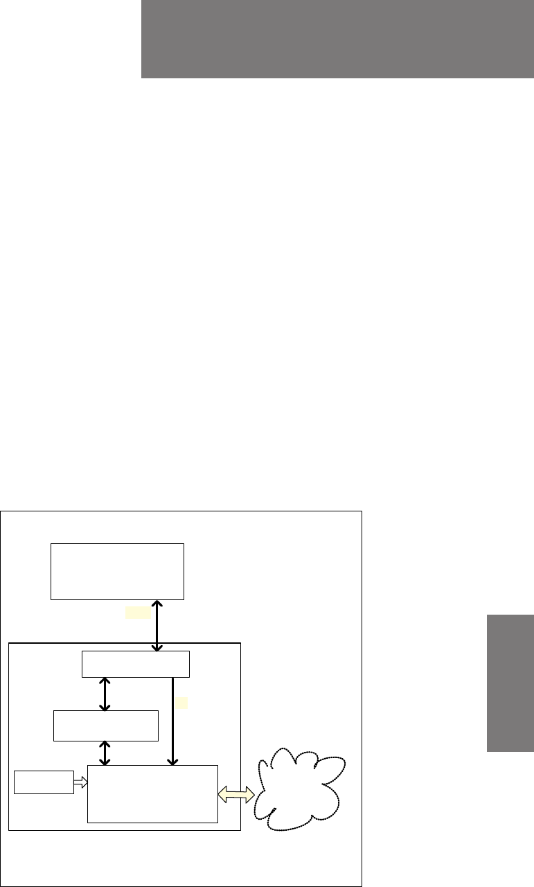
98-127093-H F-1
Appendix F
FFFF
TT-5019A Iridium Band Reject
Filter F
F.1 Introduction
You can use the AVIATOR 200/300/350 system on aircrafts with installed IRIDIUM satellite
phones. To have the SwiftBroadband and IRIDIUM service working smoothly next to each
other an Iridium Band Reject Filter must be installed between the SBU and the HLD unit.
An INMARSAT Dual RF Filter (Aircell P/N P13167) must also be inserted in the antenna coax
cable of the Iridium system.
F.1.1 System block diagram
The following block diagrams show the location of the Iridium Band Reject Filter between
the SBU and the HLD.
Figure F-1: System configuration with TT-5019A Iridium Band Reject Filter (1)
$QWHQQD
$9,$725
V\VWHP
77 $
&0 8VHU
,QWHUIDFHV
5[
5[7[
7[
77$,ULGLXP
%DQG5HMHFW)LOWHU
7[
77$+/'
77$6%8
SB-Lite.book Page 1 Tuesday, September 5, 2017 1:38 PM
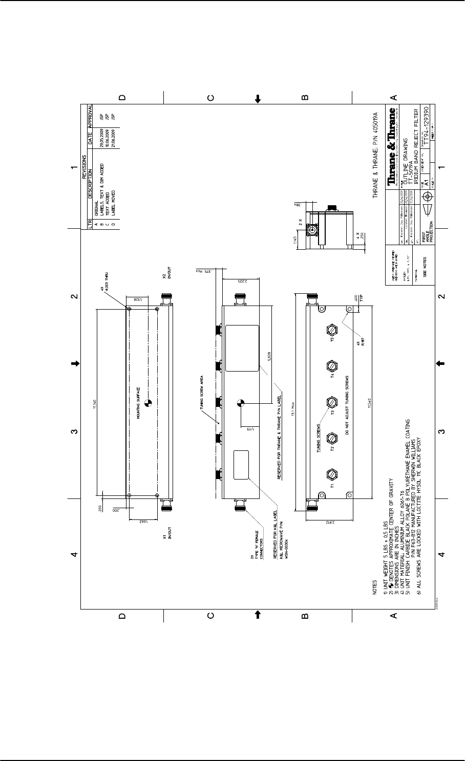
Equipment drawing
F-2 Appendix F: TT-5019A Iridium Band Reject Filter 98-127093-H
F.2 Equipment drawing
Figure F-2: Outline drawing: TT-5019A Iridium Band Reject Filter
SB-Lite.book Page 2 Tuesday, September 5, 2017 1:38 PM
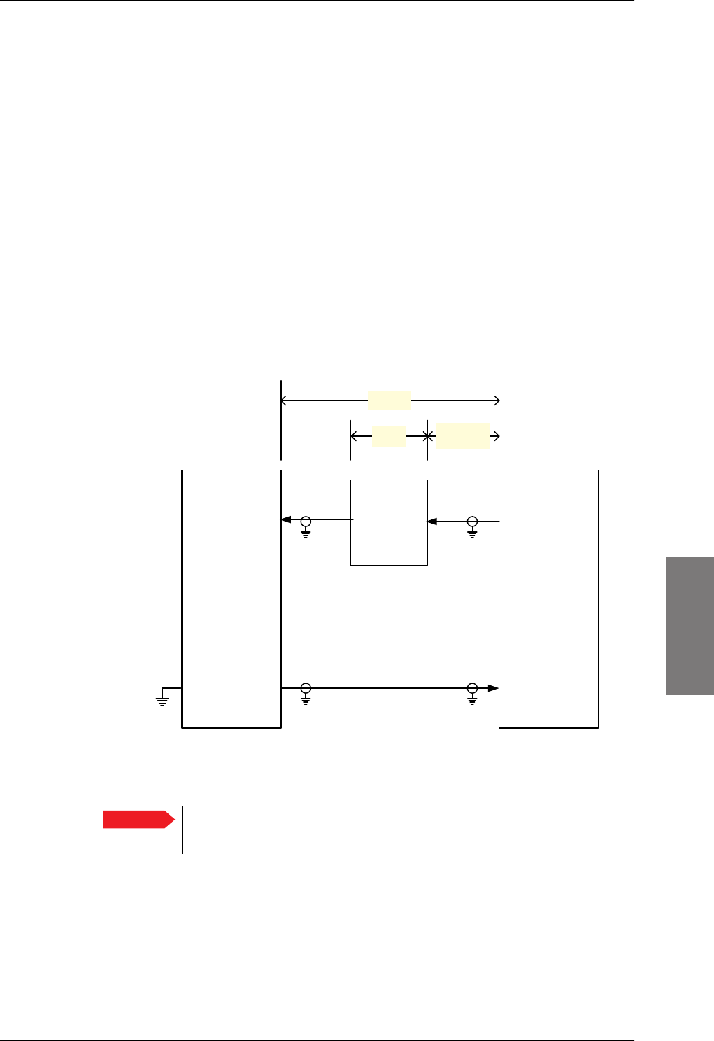
Installation
98-127093-H Appendix F: TT-5019A Iridium Band Reject Filter F-3
FFFF
F.3 Installation
F.3.1 Mounting considerations
Forced cooling is not required for the Iridium Band Reject Filter.
Mount the TT-5019A Iridium Band Reject Filter on the Tx connection between the SBU
and the HLD. The filter works in both directions.
• Install the Iridium Band Reject Filter in non-temperature controlled locations and inside
or outside pressurized locations.
• If possible mount the Iridium Band Reject Filter in a temperature controlled location to
ensure optimum performance.
• The Iridium Band Reject Filter has an attenuation of 1 dB, consider this during wiring.
• For grounding purposes, you may remove the paint around the mounting holes of the
Iridium Band Reject Filter.
AVIATOR 200: Loss of W1a + loss of W1b < 16 dB
AVIATOR 300 and AVIATOR 350: Loss of W1a + loss of W1b < 17 dB
Safe distance to Inmarsat satcom
Using Iridium and Inmarsat satcom systems on the same aircraft will normally cause
problems, because the two systems use frequency bands next to each other. The problem is
that the transmit signal from the Inmarsat satcom system will overload the receiver section
of the Iridium system. This is due to the fact that Iridium systems in general have no filters,
Figure F-3: Wiring TT-5019A Iridium Band Reject Filter
Important
:D
:
77$
+/'
77$
6%8
73$
73$;
;
7[0RGHPDQG'&
5[
0D[Pȍ ;
:E
G%
G% DVVKRUWDV
SRVVLEOH
77$
,ULGLXP
%DQG
5HMHFW
)LOWHU
SB-Lite.book Page 3 Tuesday, September 5, 2017 1:38 PM
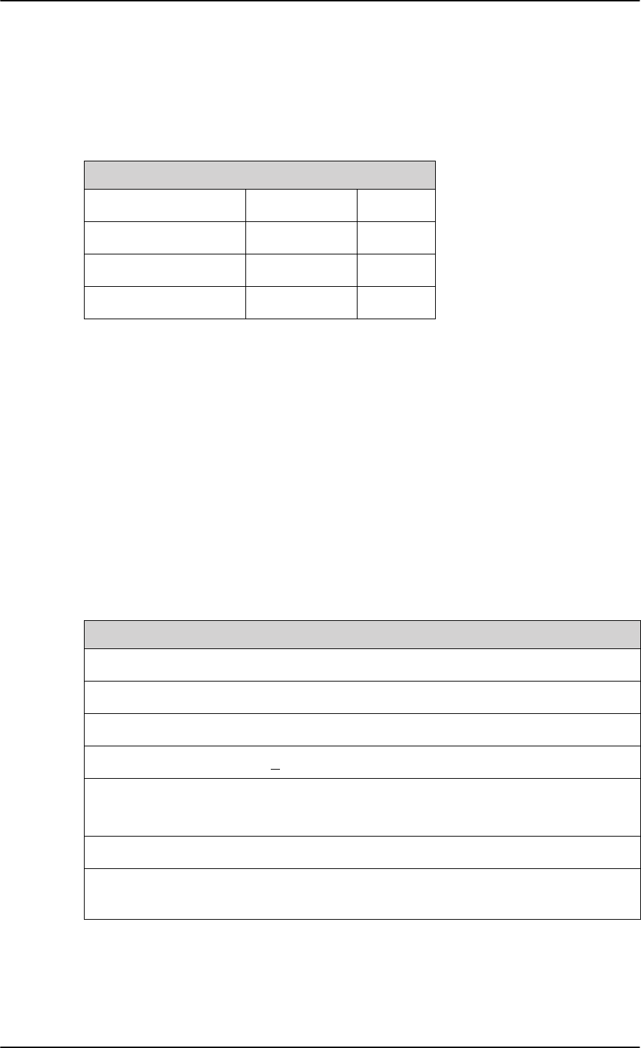
Configuration
F-4 Appendix F: TT-5019A Iridium Band Reject Filter 98-127093-H
which could ensure resilience against transmissions in adjacent bands. Appropriate filtering,
in the Inmarsat and in the Iridium systems allows having both systems. The filtering reduces
the impact to an acceptable minimum.
The following table shows the minimum distances between the two systems for various
antenna types and degrees of acceptable impact.
Table F-1: Distance to Iridium
Probability of interference / Distance between antennas
Antenna type Very low Low
LGA 1.9 m 1.3 m
IGA 3 m 2 m
HGA 7 m 4.5 m
F.3.2 Electrical installation and wiring
The filter works in both directions. Connect it to the SBU and HLD to provide the best fit in
the current installation.
F.4 Configuration
No configuration is necessary for the TT-5019A Iridium Band Reject Filter.
F.5 Specifications
Characteristics Specification
Dimensions (L x W x H) 293.12 mm x 71.37 mm x 66.04 mm (11.54” x 2.81” x 2.6”)
Weight 5 lbs +/- 0.5 lbs (2.28 kg +/- 0.23 kg)
Mounting holes 4 x 5 mm (0.2”) diameter
Insertion loss <0.1 dB at 1627.15 - 1660.5 MHz
Operating Temperature
Storage Temperature
-25C to +70C
-55C to +85C
Altitude 55000 ft
Environmental Categories Refer to Environmental Qualification form inDO-160
specifications on page F-5.
Table F-2: Equipment specifications for TT-5019A Iridium Band Reject Filter
SB-Lite.book Page 4 Tuesday, September 5, 2017 1:38 PM
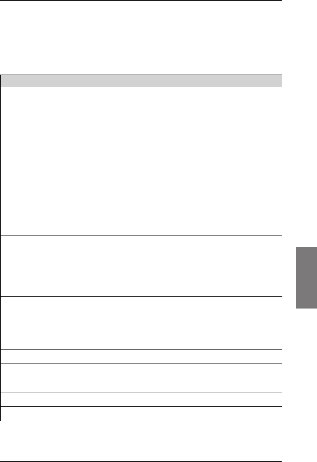
DO-160 specifications
98-127093-H Appendix F: TT-5019A Iridium Band Reject Filter F-5
FFFF
F.6 DO-160 specifications
T&T Part Number: 405019A
DO-160E string: [(A1)(F1)X]BAB[SCLM]EXXXXXZXXXXXXXXXAX
Conditions DO-160E Cat. Comments
Temperature and Altitude 4.0 A1, F1 Installation in temperature controlled
areas and inside or outside pressurized
locations.
Low Temperature 4.5.1 & 4.5.2 Short time operating low temp.: -40°C.
Min. operational temperature: -25°C.
High Temperature In-Flight
Loss of Cooling
4.5.3 & 4.5.4 Short time operating high temperature:
+70°C.
Max. operational high temp.: +55°C.
In-Flight Loss of Cooling 4.5.5 X Forced cooling is not required and not
recommended.
Altitude 4.6.1 Max. altitude: 55000 ft.
Decompression 4.6.2 Decompression at 55000 ft.
Overpressure 4.6.3 Overpressure at -15000ft.
Temperature Variation 5.0 B Installation within non-controlled
temperature locations: 5°/min.
Humidity 6.0 A Standard Humidity: 95% relative humidity
at 38°C to 50°C for 48 hours.
Installation within environmentally
controlled zones.
Operational Shocks and Crash
Safety
7.0 B Equipment tested to: Standard operational
shocks and crash safety.
Vibration 8.0 SCLM Fixed wing turbojet & turboprop/fuselage
and equipment rack: Category S, Curve C,
L & M.
Explosion Proofness 9.0 E Not hermetically sealed equipment.
Waterproofness 10.0 X No test required.
Fluids Susceptibility 11.0 X No test required.
Sand and Dust 12.0 X No test required.
Fungus Resistance 13.0 X No test required.
Table F-3: Environmental Qualification Form for Iridium Band Reject Filter
SB-Lite.book Page 5 Tuesday, September 5, 2017 1:38 PM

DO-160 specifications
F-6 Appendix F: TT-5019A Iridium Band Reject Filter 98-127093-H
Salt Spray 14.0 X No test required.
Magnetic Effect 15.0 Z Magnetic deflection distance: < 0.3 m.
Power Input 16.0 X No test required (passive device).
Voltage Spike 17.0 X No test required (passive device).
Audio Susceptibility 18.0 X No test required (passive device).
Induced Susceptibility 19.0 X No test required.
Radio Frequency Susceptibility 20.0 X No test required.
Emission of Radio Frequency
Energy
21.0 X No test required.
Lightning Induced Transient
Susceptibility
22.0 X No test required.
Lightning Direct Effects 23.0 X No test required.
Icing 24.0 X No test required.
Electrostatic Discharge (ESD) 25.0 A Operation, installation and repair in an
aerospace environment.
Fire, Flammability 26.0 X Equipment is compliant with FAR 25
Airworthiness Standards: Transport
Category Airplanes, Paragraph 25.853(a)
and Appendix F - Part I (a)(1)(ii).
Conditions DO-160E Cat. Comments
Table F-3: Environmental Qualification Form for Iridium Band Reject Filter (Continued)
SB-Lite.book Page 6 Tuesday, September 5, 2017 1:38 PM

98-127093-H G-1
Appendix G
GGGG
Terminal commands G
G.1 Get started
G.1.1 Connect to the SBU
Hardware and software requirements
The following items are required to run terminal commands:
• One IBM compatible PC with an Ethernet port available.
• One standard Ethernet cable. RJ-45<->RJ-45.
• A suitable Telnet client. In Windows XP and previous versions of Windows, you can use
the included HyperTerminal. In Windows Vista and Windows 7 you can use the included
DOS-based client, but this is not optimal. A 3rd party client that supports logging to a file
is recommended.
Prepare the telnet client
Do as follows to set up the telnet client:
1. Connect the SBU front connector to the PC Ethernet port.
2. Open the Telnet client, and make a TCP/IP (winsock) connection to IP address (host)
192.168.0.1 and port 23 (default).
3. Login with admin and 1234 (default) and press <Enter> a couple of times and confirm
that the SBU prompt telnet:/$ appears.
Option: If you need to save the output from HyperTerminal, go to the Transfer menu and
select Capture text… In other clients, the menus will be different.
SB-Lite.book Page 1 Tuesday, September 5, 2017 1:38 PM

Commands for troubleshooting the SBU
G-2 Appendix G: Terminal commands 98-127093-H
G.2 Commands for troubleshooting the SBU
G.2.1 Monitor the ARINC interfaces on the SBU
Below is an example on how to get a status for the ARINC interfaces. After the debug
command for getting the status report (first line, bold) the status report is shown.
stat -m arinc
STAT Report
Module: ARINC, Status: Ok, Message:
REPORT: SHORT
CONFIGURATION
Primary Receiver : ARINC 704-7 Inertial Reference System (IRS), speed: High
Secondary Receiver: Disabled, speed: Low
Antenna Modem : ARINC AMT-50/HGA-6000, speed: Split
STATUS ARINC DRIVER
Current Time : Thu Jan 01 00:00:54 1970
Primary Receiver : 6 RO_6_IRS_CONNECTED Qualified Forwarding forwardingPeriods:1
Secondary Receiver: 0 RO_0_NULL Await-Label Standby forwardingPeriods:0
Antenna Modem : 1 RT_1_INIT Await-Label
Primary Receiver:
Label Status Error Active Age Value Name
101 No Label 422 0 0 0.000000 HDOP
150 No Label 422 0 0 00:00:00 gnss UTC Time
260 No Label 422 0 0 00/00/00 UTC Date
273 Normal 353 69 158 Self Test GNSS Sensor Status
274 Normal 353 69 158 Self Test GPIRS Status
310 Normal 353 69 158 55.794067 N Latitude
311 Normal 353 69 158 12.523041 E Longitude
312 Normal 353 69 158 0.000000 Knots Ground Speed
313 Normal 353 69 158 0.000000 Deg Track Angle True
314 Normal 353 69 158 0.000000 E True Heading
324 Normal 353 69 158 0.010986 Deg Pitch Angle
325 Normal 353 69 159 0.120850 Deg Roll Angle
336 Normal 353 69 159 -0.015625 Deg/Sec Inertial Pitch Rate
337 Normal 353 69 159 0.000000 Deg/Sec Inertial Roll Rate
361 Normal 353 69 159 167.250000 Feet Altitude Inertial
377 Plus 353 69 159 0x004 IRS (704) Equipment Identification
Details:
273 Satellites-Tracked:0 Visible:0
273 IRS/FMS : Present Source: Primary
273 DADC/FMS: Present Source: Primary
274 Satellites-Tracked: 0
274 Primary GPSSU Validity: Valid
274 Secondary GPSSU Validity: Valid
274 GPSSU Source: Primary
377 Source Identifier: Primary
Antenna Modem:
Label Status Error Active Age Value Name
144 No Label 0 0 0 0.000000 dB Tx Gain Antenna Status
152 No Label 0 0 0 Azimu:0 Eleva:0 Open Loop Steering
SB-Lite.book Page 2 Tuesday, September 5, 2017 1:38 PM

Commands for troubleshooting the SBU
98-127093-H Appendix G: Terminal commands G-3
GGGG
350 No Label 0 0 0 Bit 25-11: 0x0 Antenna Maintenance
Details:
144 OperationalStatus: OmnidirectionalMode SDI:ALL_CALL
144 EqId:0 TrackingMode:Open HGA/IGA LNA Status:Disabled AntennaType:HGA
AntennaLocation:PORT/TOP
350 SDI: ALL_CODE
Errors / Warnings
None
COUNTERS ARINC-429: Primary Secondary Ant-Rx Ant-Tx
allocation 20 0 0
wordsA429 6752 0 0 0
discardError 0 0 0 0
framingError 0 0 0
parityError 0 0 0
overflowError 0 0 0
regStatusRead 422 0 0 FPGA Status Read
regTimeTagRead 422 0 0 FPGA TimeTag Read
regCtrlWrite 2 0 5 FPGA Control Write
interrupt 0 0 0 FPGA Interrupt
reset 0 0 0 0 Debug only
clearCounters 0 0 0 0
G.2.2 Description of the status report
The status report consists of up to seven parts:
1. Report header
2. ARINC driver configuration
3. The overall status for the ARINC driver
4. Status for the Primary ARINC Receiver
5. Status for the Secondary ARINC Receiver, if configured
6. Status for the ARINC Antenna modem, if configured
7. Low level ARINC-429 counters
Below is a detailed description of each part of the status report.
STAT Report
The following lines are part of the standard system header, there is no information relevant
for the ARINC interfaces present in the header, you may just ignore these lines:
STAT Report
Module: ARINC, Status: Ok, Message:
REPORT: SHORT
CONFIGURATION
The configuration part is a mirror of the ARINC information already available at Set up the
navigational input on page 6-44, SETTINGS > External systems of the SBU.
SB-Lite.book Page 3 Tuesday, September 5, 2017 1:38 PM
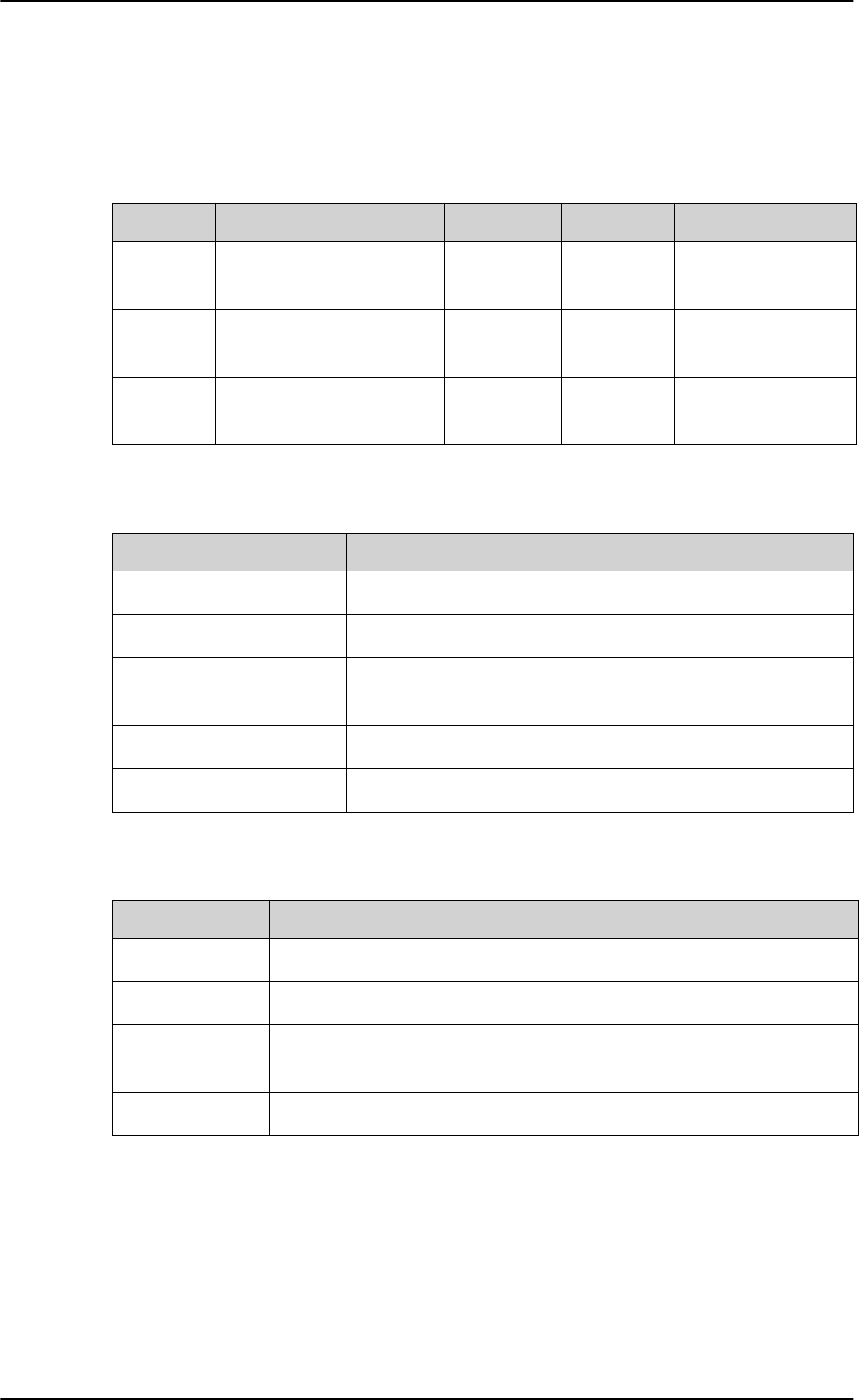
Commands for troubleshooting the SBU
G-4 Appendix G: Terminal commands 98-127093-H
STATUS ARINC DRIVER
Current Time: This is the current UTC time, if available. In this example the year 1970
indicates that the UTC time not yet is available.
Read the following overview information in the following way:
Table G-1: Status ARINC driver, overview
Interface State number and name Status Source Source Activations
Primary
Receiver
6 RO_6_IRS_CONNECTED Lost-Label Forwarding forwardingPeriods:1
Secondary
Receiver
0 RO_0_NULL Await-Label Standby forwardingPeriods:0
Antenna
Modem
1 RT_1_INIT Await-Label
The states for receivers have the following purpose:
Table G-2: Purpose of the states for receivers
State name Description
RO_0_NULL The receiver is not configured and therefore not started.
RO_1_INIT The receiver is in the progress of starting up.
RO_2_LOOPBACK A loop back test command has been running and a power-
cycle is needed.
RO_4_AHRS_CONNECTED The AHRS driver is running.
RO_6_IRS_CONNECTED The IRS driver is running.
The states for the antenna modem can be used for the following purpose:
Table G-3: Purpose of the states for the antenna modem
State name Description
RT_0_NULL The antenna modem is not configured and therefore not started.
RT_1_INIT Awaits the BSU (Beam Steering Unit) start sending the status word.
RT_2_LOOPBACK A loop back test command has been running and a power-cycle is
needed.
RT_3_AMT50 The ARINC AMT-50 / HGA-6000 driver is running.
SB-Lite.book Page 4 Tuesday, September 5, 2017 1:38 PM
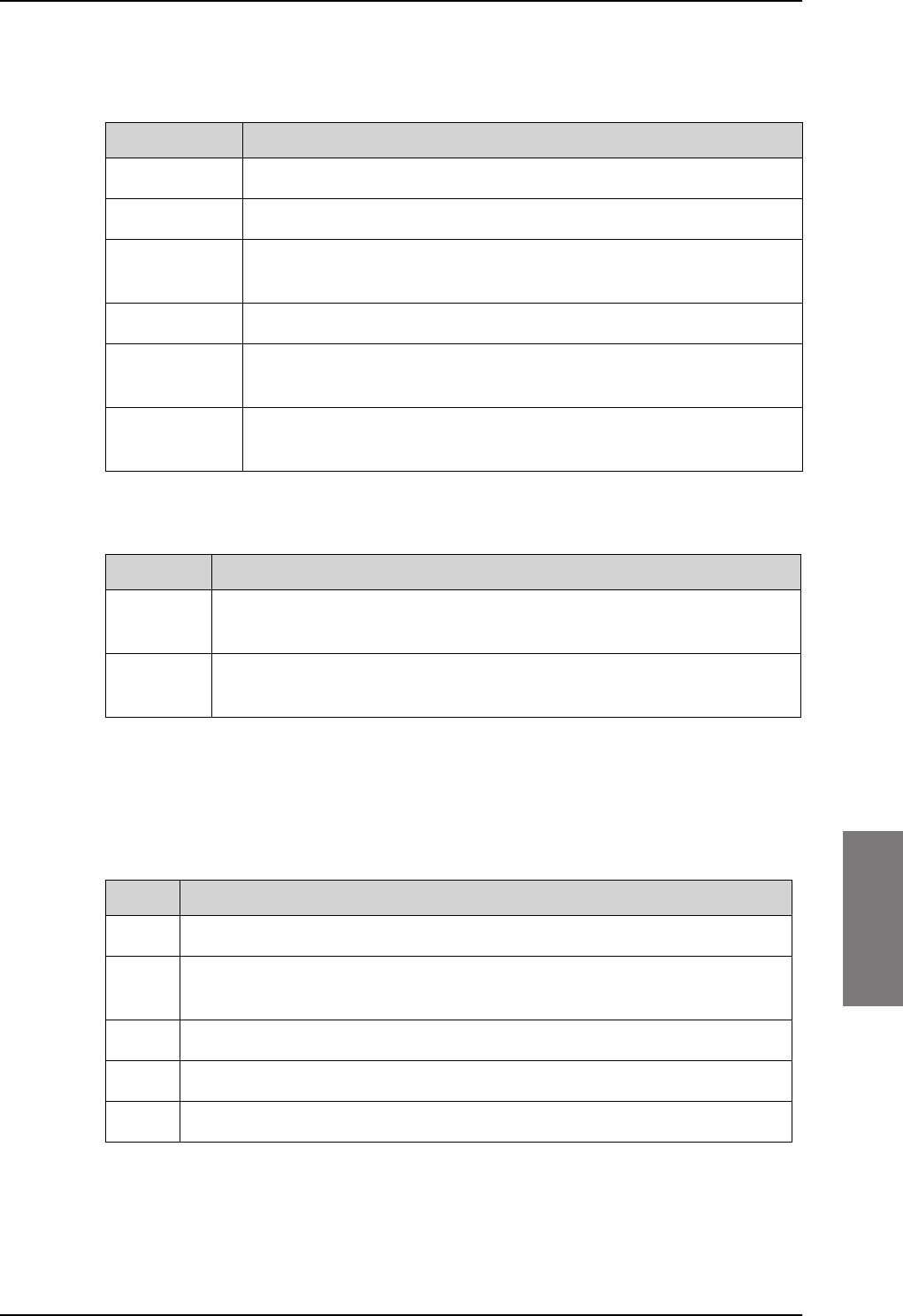
Commands for troubleshooting the SBU
98-127093-H Appendix G: Terminal commands G-5
GGGG
Status: This reflects the overall status considering all mandatory labels on the interface in
question.
Table G-4: Status for all mandatory labels on the interface in question
Status Description
Await-Label At least one mandatory label has never showed up on the interface.
Lost-Label A label previously received is now missing on the interface.
Unreliable May be used in the future for selecting between two channels where
one of them is more degraded than the other.
Degraded One or more of the labels is degraded.
Evaluation All mandatory labels are operational and has to be stable for a period of
time before they can be qualified.
Qualified All mandatory labels are operational and this port can now be
forwarded.
Source:
Table G-5: Status ARINC driver: Source
Source Description
Forwarding This ARINC receiver is forwarding valid navigational date to the SBU.
Forwarding means that the data on the interface is used by the system.
Standby This ARINC receiver is on standby and not forwarding data to the SBU.
Standby means that the data on the interface are not used by the system.
Forwarding Periods: The number of periods the interface has being forwarding data to
the system.
RECEIVER
Header Description
Label The label number in octal number system.
Status Take status of the label word according to bit 30 and 31 Sign/Status Matrix.
See table directly below.
Error The number of 100mS interval the label has not been operational.
Active The number of 100mS interval the label has been operational.
Age The age of the label in ms sampled every 100 ms.
Table G-6: Receiver: Header line for the table
SB-Lite.book Page 5 Tuesday, September 5, 2017 1:38 PM

Commands for troubleshooting the SBU
G-6 Appendix G: Terminal commands 98-127093-H
The specific label type (BCD/BNR/DISC) can be looked up in the ARINC-429 Specification.
Table G-7: Status for label types
Status BCD BNR DISC
0 Plus Failure Normal
1 No Data No Data No Data
2 Test Test Test
3 Minus Normal Failure
The underlined status is the operational state for the specific label type.
Value The decoded value of the label
Name The name of the label according to ARINC-429
Header Description
Table G-6: Receiver: Header line for the table (Continued)
SB-Lite.book Page 6 Tuesday, September 5, 2017 1:38 PM

98-127093-H H-1
Appendix H
HHHH
SIP setup for Wifi-enabled phones H
H.1 Introduction
The built-in PBX of the AVIATOR 200/300/350 can route VoIP calls that are terminated in
the SIP server of the SBU. If you have a phone with a SIP client and WLAN interface you
can connect to the SBU via WLAN and configure the SIP client in your phone to
communicate with the SBU. After successful configuration you can use your phone to make
calls through the AVIATOR
200/300/350 system.
There are two tasks you have to do:
•Connect to the WLAN interface
•Set up a SIP profile
H.1.1 Connect to the WLAN interface
To connect to the WLAN interface of the SBU, do as follows:
1. Refer to the user documentation of your phone for instructions how to connect to a
wireless access point.
2. You can see the name of the wireless network in the web interface at SETTINGS >
WLAN, SSID. The default value is the name of the system type, for example ‘AVIATOR
200’.
H.1.2 Set up a SIP profile
SIP telephony and SIP profiles
If your phone has an integrated SIP (Session Initiation Protocol) client you can use SIP
telephony between your phone and the SBU, which has an integrated SIP server.
How to set up the SIP profile in your phone depends on your subscription, the SIP server in
the terminal and the network which your phone is connected to, in this case the WLAN
network on board the aircraft.
Where to get a SIP client application
If your smartphone does not have a SIP client, you can download one from one of the links
below:
• Apple iPhone App store (www.apple.com/iphone/from-the-app-store/)
• Android Market (www.android.com/market/)
Note The SIP client is a third party application. Thrane & Thrane
dose not offer technical support for it.
SB-Lite.book Page 1 Tuesday, September 5, 2017 1:38 PM

Introduction
H-2 Appendix H: SIP setup for Wifi-enabled phones 98-127093-H
To setup a SIP profile
Setup a SIP profile if you want to connect the SIP client of your phone to the SIP server of
the terminal. You need to enter several network specific values so your phone can
communicate with the SIP server.
Depending on your phone, some or all of the following parameters may have to be set up in
the SIP profile of your phone:
• Profile name
• SIP server and port
• User name
• Password
• Codec priority
• Realm
• Audio configuration, Silence support
User name: When connecting to the AVIATOR 200/300/350, the user name should be a
local number, i.e. 05xx. This must be configured in the built-in web interface under
SETTINGS > IP handsets.
Password: When connecting to the AVIATOR 200/300/350, the password must match the
IP Handset password entered in the web interface of the AVIATOR
200/300/350 on the
page SETTINGS > IP handsets.
Codec priority: The SIP client must have G.729A as highest priority codec and G.711 A-
LAW as second highest priority. The G.729A codec is required for the Multi-voice option.
Realm: When asked for Realm enter the serial number of the SBU.
Audio configuration, Silence support enable: Set to No. The phone should not stop
sending data packets even though there is silence and no one speaks.
SB-Lite.book Page 2 Tuesday, September 5, 2017 1:38 PM

98-127093-H Glossary-1
9999
Glossary
Glossary 9
A
ACARS Airborne Communications Addressing and Reporting System
AHRS Attitude and Heading Reference System
APN Access Point Name. The Access Point Name is used by the terminal operator to establish
the connection to the required destination network.
ARINC Aeronautical Radio, Incorporated. A provider of transport communications and systems
engineering solutions
AT AT commands are used for controlling modems.
AWG American Wire Gauge
B
BGAN Broadband Global Area Network, simultaneous voice and broadband data
BITE Built-In Test Equipment. A BITE error is a hardware error detected by the automatic error
detection system in the AVIATOR 700 System.
BSU Beam Steering Unit
C
CID Context Identifier
CM Configuration Module
CMU Communications Management Unit
CPDLC Controller-Pilot Data Link Communications, a method for air traffic controllers to
communicate with pilots over a datalink system. , ,
D
dB decibel ,
DC Direct Current
DCE Data Communication Equipment. Equipment that does not generate data, but only relays
data generated by someone else.
DHCP Dynamic Host Configuration Protocol. A protocol for assigning dynamic IP addresses to
devices on a network. With dynamic addressing, a device can have a different IP address
every time it connects to the network.
DTE Data Terminal Equipment
DTMF Dual Tone Multi Frequency. The signal to the phone company that is generated when you
press an ordinary telephone’s touch keys. DTMF has generally replaced loop disconnect
(pulse) dialing.
E
ECS Electronic Cable Specialists, Inc., a Carlisle IT company
SB-Lite.book Page 1 Tuesday, September 5, 2017 1:38 PM

Glossary
Glossary-2 98-127093-H
EIRP Effective Isotropic Radiated Power
EMC Electromagnetic Compatibility
eMLPP enhanced Multi-Level Precedence and Pre-emption
ETSI European Telecommunication Standard Institute
F
FAA Federal Aviation Administration
FNBDT Future Narrowband Digital Terminal. A US Government standard for secure voice
communication.
G
Glonass GLObal’naya NAvigatsionnaya Sputnikovaya Sistema, Global Navigation Satellite System
in English
GNSS Global Navigation Satellite System
GPS Global Positioning System
H
HLD High Power Amplifier, Low Noise Amplifier and Diplexer in one unit
I
I/O Input/Output
IAI-2 Inmarsat Air Interface-2. The air interface used for BGAN. IAI-2 is an evolution of MPDS
with new bearer types, which give a wide range of data rates from 16 kbps up to 492 kbps.
By utilizing different modulation schemes, variable coding rate and power adjustment, it
is possible to change the bearer type to give optimum throughput with efficient use of the
satellite resources.
ICAO International Civil Aviation Organization
ICG International Communications Group
IEEE Institute of Electrical and Electronics Engineers
IMEI International Mobile Equipment Identity. A unique number identifying your terminal
IMSI International Mobile Subscriber Identity
IP Internet Protocol
IP Internet Protocol, used for communicating data across a packet-switched internetwork.
IRS Inertial Reference System
ISDN Integrated Services Digital Network
ISP Internet Service Provider
ITU International Telecommunication Union
SB-Lite.book Page 2 Tuesday, September 5, 2017 1:38 PM

Glossary
98-127093-H Glossary-3
9999
L
LAN Local Area Network
LED Light Emitting Diode
LGA Low Gain Antenna ,
LLC Limited Liability Company
LRU Line Replaceable Unit. A separate unit or module which can easily be replaced. Examples
are the SDU and the HPA.
M
MIB Management Information Base
MOD Modification
MSN Multiple Subscriber Numbering. In most pieces of ISDN equipment you can program
multiple subscriber numbers. The number programmed into the equipment should be the
dial-in number that you wish that piece of equipment to answer.
N
NAT Network Address Translation. An Internet standard that enables a local-area network to
use one set of IP addresses for internal traffic and a second set of addresses for external
traffic. A NAT module makes all necessary address translations.
NC No Connect
nON Power-on control signal, active low
NPI Navigation Position Information, a Thrane abbreviation
NRS Navigation Reference System
NT Network Termination. A device connecting the customer’s data or telephone equipment
to the local ISDN exchange carrier’s line. It provides a connection for terminal equipment
(TE) and terminal adaptor (TA) equipment to the local loop.
P
PAST Person Activated Self Test
PBX Private Branch Exchange, telephone exchange that serves a particular business or office.
PC Personal Computer
PDF Portable Document Format, a file format created by Adobe Systems for document
exchange
PDP Packet Data Protocol. A network protocol used by external packet data networks that
communicate with a GPRS network.
POST Power On Self Test. A system test that is activated each time the system is powered on.
POTS Plain Old Telephone Service
PS Packet switched
SB-Lite.book Page 3 Tuesday, September 5, 2017 1:38 PM

Glossary
Glossary-4 98-127093-H
Q
QoS Quality of Service
S
SAL System Address Level
SATCOM Satellite Communications
SB Swift Broadband, based on BGAN and offers similar services, simultaneous voice and
broadband data.
SBU SwiftBroadband Unit. Unit in the system providing access to the aeronautical BGAN
service, SwiftBroadband.
SDU Service Data Unit. Also known as a data packet.
SIM Subscriber Identity Module
SIP Session Initiation Protocol. An application-layer control (signaling) protocol for creating,
modifying, and terminating sessions with one or more participants. Used e.g. for Internet
telephony.
SNMP Simple Network Management Protocol. An Internet-standard protocol for managing
devices on IP networks. It is used mostly in network management systems to monitor
network-attached devices for conditions that warrant administrative attention.
SSA Security Safety Analysis , ,
SSID Service Set IDentifier. An SSID is the name of a wireless local area network (WLAN). All
wireless devices on a WLAN must use the same SSID in order to communicate with each
other.
STC Supplemental Type Certificate. FAA or EASA certification document issued to companies
that perform significant modifications on an aircraft.
STE Secure Terminal Equipment
STU Secure Telephone Unit
T
TE Terminal Equipment
TFTP Trivial File Transfer Protocol. A very simple file transfer protocol, with the functionality of
a very basic form of FTP. Since it is so simple, it is easy to implement in a very small
amount of memory.
TP Top Plug
W
WLAN Wireless Local Area Network
SB-Lite.book Page 4 Tuesday, September 5, 2017 1:38 PM

98-127093-H Index-1
10101010
Index
Index 10
Numerics
2-Wire Cradle
connector functions, 4-11
DB9 male connector, 4-11
Environmental Qualification Form, B-8
outline drawing, 3-9
specifications, A-7
2-Wire Handset
Environmental Qualification Form, B-8
outline drawing, 3-8
specifications, A-7
2-wire interface
setting call type, 6-24
A
AAGW
setup, 6-51
about this manual, 1-1
ACARS
password requirements, 6-72
setup, 6-51
wiring, 5-28
Access Point Name, 6-27
activation
SIM card, 5-50
additional numbers
description, 6-92
enter, 6-16
address
manufacturer, -ii
administration settings, 6-71
administration, remote, 6-89
administrator
log off, 6-74
log on, 6-72
password, reset, 6-74
administrator password
requirements, 6-72
advanced configuration
WLAN, 6-22
AFIS
wiring, 5-28
AGGW
setup, 6-51
AHRS
navigational input, 5-4
wiring, 5-25
AHRS/GPS, 5-4
air interface
status, 7-16
AirCell Axxess
contact information, 2-13
aircraft
interfaces, 4-6
mating connectors, 4-12
airtime services, 5-50
Airworthiness, Continued, 7-1
AIS 380 Aircraft Interface Module, 2-13, 4-7,
6-51
wiring, 5-17
alarms
log, 7-16
view, 7-16
AMT-3800
wiring, 5-20
annunciators
default setting, 4-5
wiring, 5-42
antenna
connectors, 4-9
Glonass distance, 5-6
GPS distance, 5-6
mounting, 5-4
supported types, 2-9
systems, 2-4
viewing properties, 6-17
viewing status, 6-12
viewing type, 6-12, 7-16
wiring, 5-10
antenna steering, 5-4
antenna upgrade, 6-40
APN, 5-50
common, 6-27
setup, 6-27, 6-28
ARINC
stat command, G-2
stat report, G-2
ARINC 404
connectors, 4-1
ARINC 429
wiring, 5-25
ARINC sources, 6-45
SB-Lite.book Page 1 Tuesday, September 5, 2017 1:38 PM

Index
Index-2 98-127093-H
assigned numbers, 6-92
assistance, telephone number, 7-1
AT commands, 6-88
ATE pins, 5-46
automatic test equipment pins, 5-46
AVIATOR Wireless Handset
connect, 6-34
setup, 6-35
setup call types, 6-36
B
backup.configuration, 6-75
barring calls, 6-30
bit error ratio, 6-81
bit rates
streaming class, 2-3
block diagrams, 2-14
Broadcast SSID, 6-23
browser settings
for web interface, 6-9
browsers supported, 6-6
buttons
Push To Test, 7-11
C
cable loss, 6-43
antenna system, 5-23
RF cables, 5-10
WLAN, 5-36
cable specification
SBU maintenance connector, 4-2
cables
allowed lengths for power, 5-47
ARINC 429, 5-29
ARINC 429, recommended types, 5-49
discrete signals, 5-50
Ethernet, 5-49
Ethernet, recommended, 5-49
ISDN, requirements, 5-37
maximum length for HLD, 5-47
maximum length, SBU to HLD, 5-49
maximum length, WLAN, 5-49
power, recommended types, 5-48
recommended, 5-47
RF, general requirements, 5-6
RF, recommended types, 5-48
SBU power supply, 5-10
WLAN, max. length, 5-49
calibration
analysis, 6-48
magnetometer, turn radius, 6-48
NRS, 6-46
calibration procedure
magnetometer, 6-47
call charges
calls, 6-77
call limiting, 6-91
call log
clear, 6-78
Call output, 6-38
call type
setting for AVIATOR Wireless Handset, 6-36
setting for ISDN, 6-26
setting for Phone/Fax interface, 6-24
calls
barring, 6-30
closed user group, 6-33
forwarding, 6-29
line identification, 6-32
ongoing, 7-17
viewing ongoing, 6-13
waiting indication, 6-31
charges
calls, 6-77
data sessions, 6-77
Chime/Lamps Inhibit
configuration, 6-37
wiring, 5-42
Circuit breaker
specifications, 2-11
circuit breaker, 5-10
Class 15
services, 2-3, 6-91
Class 6
services, 2-3, 6-91
Class 7
services, 2-3, 6-91
clearing logs, 6-78
clearing usage counter, 6-78
closed user group, 6-33
CM
DO-160 form, B-4
Environmental Qualification Form, B-4
CMU support, 6-51
CMU, wiring, 5-28
CMU/ACARS, 2-5
configuration, 6-51
Coax, 5-8
Cockpit reserve, 6-95
SB-Lite.book Page 2 Tuesday, September 5, 2017 1:38 PM

Index
98-127093-H Index-3
10101010
common network settings, 6-27
configuration
cable losses, 6-43
discrete I/O, 6-38
exporting to file, 6-75
importing from file, 6-76
input of navigational systems, 6-44
ISDN, 6-25
LAN, 6-19
phone systems, 6-99
phone, fax, 6-24
step-by-step, 6-7
upload, 6-76
web interface, 6-2
WLAN, 6-22
configuration data
enter, 2-4, 6-6
Configuration Module, 2-4
configuration of SBU
backup, 6-75
connect
AVIATOR Wireless Handset, 6-34
connection
standard data, 6-14
start or stop, 6-14
connectors, 4-1
2-Wire Cradle, 4-11
antenna, 4-9
ARINC 404, 4-1
Configuration Module, 4-1
HLD, 4-9
Maintenance front, 4-1
mating, in aircraft, 4-12
part number, 2-12
SBU front, 4-1
SBU rear receptacle, 4-3
contact
address, -ii
contact information, 7-3
AirCell Axxess, 2-13
ICG DECT Cordless Handset, 2-12
Sigma7 handset, 2-13
Switch Annunciator panel, 2-13
Continued Airworthiness, 7-1
cooling requirements, 5-3
counter reset, 6-78
Country
selecting for WLAN, 6-23
country code
WLAN, default, D-1
WLAN, US, D-2
D
dashboard, 6-12
data
profiles, 6-78
traffic flow filters, 6-82
data limits, 6-78
data sessions
cost, 6-77
viewing ongoing, 6-13
debug command
ARINC, G-2
default button, 7-14
default netmask, 7-15
defect units, 7-1
DHCP, 6-19
no router option, single user, 6-19
DHCP request, 6-14
diagnostic report, 7-3, 7-18
dimensions
HLD, A-3, A-4, A-5
SBU, A-2
direct dial
local phone, 6-34
disable
WLAN, 6-22, 6-24
discrete I/O
configuration, 6-38
discretes
types and description, 5-44
wiring, 5-42
DO-160 forms, B-1
2-Wire Handset and Cradle, B-8
CM, B-4
HLD, B-4
Iridium Band Reject Filter, F-5
SBU, B-2
drawings, 3-1
2-Wire Cradle, 3-9
2-Wire Handset, 3-8
HPA Tray, 3-11
Rx Power Splitter, 3-4
SBU, 3-2
SBU Tray connector, 3-13
SDU Tray, 3-11
Switch Annunciator Panel, 3-17
E
electrical installation, 5-8
SB-Lite.book Page 3 Tuesday, September 5, 2017 1:38 PM

Index
Index-4 98-127093-H
enable, 6-22
WLAN, 6-22
encryption key, 6-23
Environmental Qualification Forms, B-1
2-Wire Handset and Cradle, B-8
CM, B-4
HLD, B-4
Iridium Band Reject Filter, F-5
SBU, B-2
error codes, C-1
error correction for data packets, 6-81
Ethernet interface
setting up, 6-19
Eval.Prec. Index, 6-83
events
list of, C-2
list of active, 7-16
exchanging units, 7-1
exporting configuration, 6-75
extended status, 7-4, 7-16
external access, 6-89
External systems, 6-45
F
factory settings, 7-15
Fail/Pass LED, SBU, 7-12
features, 2-7
FLEX key sequence, 6-53
forwarding calls, 6-29
front connector
SBU, 4-1
G
Glonass antenna
distance from antenna, 5-6
GNSS, 5-4, 5-5, 5-25
ARINC data format, 5-27
GPS antenna, 5-2, 5-4, 6-45
cable loss, 5-30
distance from antenna, 5-6
gain, 5-30
input, 4-6
interference, 5-6
wiring, 5-29
ground speed, 5-26
grounding
HLD, 5-3
H
handset contexts for Multi-voice, 6-92
handsets
AVIATOR Wireless, configuration, 6-34
initial configuration, 6-99
wiring, 5-37
header compression, 6-65
heading, 5-26
magnetic, 5-26
Heading Offset, 6-43
help desk number, 7-3
changing in web interface, 7-3
helpdesk
telephone number, 7-1
HGA
services, 2-3, 6-91
High Gain Antenna, 2-3, 6-91
HLD
cable length, 5-47
connectors, 4-9
cooling, 5-3
dimensions, A-3, A-4, A-5
DO-160 form, B-4
Environmental Qualification Form, B-4
grounding, 5-3
location in aircraft, 5-3
mounting, 5-3
specifications, A-3
hotline
telephone number, 7-1
I
IAI
air interface status, 7-16
ICG DECT Cordless Handset
contact information, 2-12
initial configuration, 6-99
wiring (2-wire), 5-41
ID
SBU software, 7-8
IGA
services, 2-3, 6-91
IMEI number, 6-12
importing configuration, 6-76
IMSI number, 5-51
inoperative units, 7-1
input
GPS antenna, 4-6
SB-Lite.book Page 4 Tuesday, September 5, 2017 1:38 PM

Index
98-127093-H Index-5
10101010
installation kit
contact information, 2-12
part number, 2-12
installation kits
supplier, 5-1
interface
SNMP, 6-71
WLAN, disable, 6-24
interface for software upgrades, 4-2
interfaces, 5-1
user, 2-19
interference
GPS antenna, 5-6
Iridium, F-4
Intermediate Gain Antenna, 2-3, 6-91
IP address, 7-14
default, 7-14
external, setting up, 6-61
for connected device, 6-62
for web interface, 6-8
local, setting up, 6-20
local, viewing, 6-12
reset, 7-14
IP connection
monitoring, 6-90
IP handset
setting call type, 6-36
setting up, 6-34
Iridium
distance to Inmarsat antenna, F-4
interference, F-4
Iridium Band Reject Filter, F-1
DO-160 form, F-5
Environmental Qualification Form, F-5
equipment drawing, F-2
mounting, F-3
specifications, F-4
IRIDIUM filter, 2-6, F-1, H-1
IRS, 5-4
navigational input, 5-4, 6-44
wiring, 5-25
ISDN
cable requirements, 5-37
interface description, 5-37
pins, 5-36
setup, 6-25
wiring, 5-36
ISDN interface
setting up, 6-25
ISDN routing
phone, fax and data, 5-38
L
lamp driver interface
specifications, 5-44
LAN
managing network users, 6-57
setting up interface, 6-19
setup, 6-19
LAN communication, 6-14
LEDs on SBU
Fail/Pass, 7-12
Logon, 7-12
Maintenance connector, 7-13
Power, 7-12
system ready, 6-100
LGA
services, 2-3, 6-91
limit calls, 6-91
limiting
data services, 6-78
streaming, 6-78
line identification, 6-32
link monitoring, 6-90
local exchange, 6-34
Multi-voice, 6-34
location
HLD non-temperature controlled, 5-3
SBU temperature controlled, 5-3
log off
administrator, 6-74
log on
administrator, 6-72
Logon LED
on SBU, 7-12
logs, clearing, 6-78
Low Gain Antenna, 2-3, 6-91
low pass filter, 5-34
WLAN, order information, 5-35
M
MAC address, 6-12
magnet
distance from, for IGA, 5-6
magnetic environment, 5-5, 5-6
calibration, 6-46
magnetometer
calibration analysis, 6-48
calibration procedure, 6-47
magnetometer calibration
turn radius, 6-48
SB-Lite.book Page 5 Tuesday, September 5, 2017 1:38 PM

Index
Index-6 98-127093-H
Maintenance connector
functional description, 4-2
LED, 7-13
PC and Reset, wiring, 5-45
pin-out, 4-2
Maintenance interface
pin allocation, 5-46
manufacturer
address, -ii
menu tree, 6-7
messages, C-1
MIB files, 6-71
minimum setup
SBU, 6-2
minimum system
drawing, 5-2
mobile numbers
viewing and editing, 6-15
model numbers, applicable, 2-9
monitoring external IP connection, 6-90
mounting considerations, 5-3
antenna, 5-4
HLD, 5-3
Iridium Band Reject Filter, F-3
magnetic environment, 5-6
SBU, 5-3
WLAN antenna, 5-7
MSN number, 6-26
Multi-voice, 2-5, 6-16, 6-95
additional numbers, 6-92
additional numbers, assign to 2-wire, 6-25
additional numbers, assign to AVIATOR
Wireless Handset, 6-36
additional numbers, assign to ISDN, 6-26
handset contexts, 6-92
local exchange, 6-34
number of calls, 2-3
N
NAT, 6-66
NAV source
wiring, 5-25
navigation in web interface, 6-9
navigational input, 6-44
AHRS/IRS, 5-4
enter in configuration, 6-44
Heading Offset, 6-43
IRS in SBU, 6-44
Pitch Offset, 6-43
Roll Offset, 6-43
SBU, 6-6
wiring, 5-25
netmask
default, 7-15
Network Address Translation, 6-66
network management, 6-57
network terms
definitions, 6-65
NPI, 5-4, 5-5, 5-25
ARINC data format, 5-27
NRS, 5-4
calibration, 6-46
minimum distance for magnetic interference,
5-6
O
options
FLEX keys, 6-53
outline drawings, 3-1
P
packaging for return, 7-19
part number
installation kit, 2-12
part numbers, 2-9
connector, 2-12
installation kit, 2-12
password
safety requirements, 6-72
password requirements
ACARS, 6-72
PAST, 7-11
PC, Maintenance
wiring, 5-45
PDP context, 6-14
permissions
user, 6-87
Person Activated Self Test, 7-11
phone book, 6-15
phone numbers for terminal, 6-15
SB-Lite.book Page 6 Tuesday, September 5, 2017 1:38 PM

Index
98-127093-H Index-7
10101010
Phone/Fax
setup, 6-24
Phone/Fax interface
setting call type, 6-24
phonebook
limit calls to, 6-91
phones
wiring, 5-37
PIN
administration PIN, 6-72
ping command from SBU, 6-90
pin-out, 4-1
2-Wire Cradle, DB9 connector, 4-11
ISDN, 5-36
Maintenance interface, 5-46
SBU front connector, 4-2
SBU rear receptacle, 4-7, 4-8
pitch angle, 5-26
Pitch Offset, 6-43
pitch rate, 5-26
port forwarding, 6-20
POST, 7-11
POTS interface
configuration, 5-38
power cables, 5-10
recommended, 5-48
Power LED
on SBU, 7-12
Power On Self Test, 7-11
power splitter
DO-160 string, B-6
equipment drawing, 3-4
specifications, A-5
PPPoE
connection, 6-67
network connections, 6-68
setup, 6-68
setup equipment, 6-68
PPPoE setup
non-default APN, 6-69
profiles for data transmission, 6-78
properties
antenna, 6-17
system, 6-12
protect
change of SBU setup, 6-87
protection
SBU setup, 6-71
protocol number, 6-84
provisioning, 5-50
Proxy server, disabling, 6-9
Push To Test button, 7-11
Q
QoS, 6-79
Quadrax connector
wiring, 5-33
Quality of Service, 6-79
quick start
SBU, 6-2
R
rear receptacle
SBU pin-out, 4-7, 4-8
reboot, 6-18, 7-17
references, E-1
remote control
SBU, 6-90
remote management, 6-89
Repackaging requirements, 7-19
repair, 7-1
returning units, 7-19
reports
distance, 6-54
interval, 6-54
position, 6-54
server connection, 6-54
Reset
wiring, 5-45
reset
default IP-address, 7-14
during self test, 7-17
password, 6-74
reset administrator password, 6-74
reset time counter for calls, 6-78
reset to factory settings, 7-15
residual bit error ratio, 6-81
restricted dialing, 6-36, 6-91
returning units, 7-19
RF cable requirements
WLAN, 5-35
RF settings
SBU, 6-43
roll angle, 5-26
Roll Offset, 6-43
roll rate, 5-26
router option
limit when not available, 6-7
limits in single user mode, 6-19
SB-Lite.book Page 7 Tuesday, September 5, 2017 1:38 PM

Index
Index-8 98-127093-H
RS-232 Maintenance
wiring, 5-45
RTCA DO-160 forms, B-1
Rx Power Splitter
outline drawing, 3-4
specifications, A-5
S
satcom antenna
cable loss, 5-23
satcom antennas, 2-4
satellite
view selected, 6-13
SB-Safety Voice
limitations, 6-56
setup, 6-55
SBU
configuration backup, 6-75
cooling, 5-3
dimensions, A-2
DO-160 form, B-2
Environmental Qualification Form, B-2
front connector, 4-1
front connector, pin-out, 4-2
location in aircraft, 5-3
maximum cable length, 5-49
mounting, 5-3
outline drawing, 3-2
power cables, 5-10
protect for setup change, 6-87
quick start, 6-2
rear receptacle, 4-3
remote control, 6-90
software version, 7-5
specifications, A-2
Tray connector, outline drawing, 3-13
SBU Enable, 5-43
SBU Failed, 5-42, 6-37
SBU nON, 5-43
SBU nOn
remote on/off, 5-43
SBU setup
protection, 6-71
SBU software ID, 7-8
SDU and HPA Tray
outline drawing, 3-11
security key
wireless network, 6-23
self test, 7-17
serial number, 6-12
server connection
reports, 6-54
Service Available, 6-37
service log, 7-18
services
supplementary, 6-25
services available, 2-3
sessions
ongoing, 7-16
SETTINGS page, 6-17
setup, 5-50
AVIATOR Wireless Handset, 6-35
SBU minimum, 6-2
show number, 6-32
Sigma7 handset
contact information, 2-13
Sigma7 handsets
initial configuration, 6-99
wiring, 5-40
SIM card activation, 5-50
SIM default, 6-28
SIM Lock, 6-85
SIM PIN, 6-85
single user, 6-19
single-user mode, 6-19
SIP client
where to get, H-1
SIP profile, H-1
SIP setup, H-1
SIP telephony, 5-37
site map, 6-98
SMS control
SBU, 6-90
SNMP, 6-71
software
viewing version, 6-12
software identification
SBU label, 7-8
software update, 7-5
software upgrades
interface, 4-2
software version
minimum, 7-5
SB-Lite.book Page 8 Tuesday, September 5, 2017 1:38 PM

Index
98-127093-H Index-9
10101010
specifications, A-1
2-Wire Cradle, A-7
2-Wire Handset, A-7
circuit breaker, 2-11
HLD, A-3
Iridium Band Reject Filter, F-4
Rx Power Splitter, A-5
SBU, A-2
WLAN antenna, A-5
Splitter
outline drawing, 3-4
specifications, A-5
SSID, 6-23
standards, applicable, E-1
start connection, 6-14
static IP address
device connected to SBU, 6-19
static route, 6-70
status
air interface, 7-16
connection, 7-16
extended, 7-16
ongoing calls and data sessions, 6-13
viewing, 6-12
status information, 7-4
streaming, 2-3
limit, 6-78
streaming class
bit rates, 2-3
streaming classes, 2-3
streaming rates, 2-3
supplementary services
setting up, 6-25
support
contact details, 7-1
contact information, 7-3
phone numbers, 7-1
Switch Annunciator Panel
contact information, 2-13
outline drawing, 3-17
wiring, 5-44
system drawing
minimum, 5-2
system messages, C-1
system ready, 6-100
system type, 6-39
change, 6-40
upgrade, 6-42
system, minimum, 2-9
T
tariffs, 6-77
telephone interface
setting call type, 6-24
temperature controlled
HLD, non, 5-3
SBU, 5-3
time connected, 6-78
time counter
calls, reset, 6-78
total usage
viewing, 6-13
track angle, 5-26
tracking, 6-54
traffic class, 6-80
traffic flow filters, 6-82
Transfer delay, 6-81
troubleshooting, 7-11
diagnostic report, 7-3
TT-3002A LGA
wiring, 5-11
TT-5006A-IGA
wiring, 5-12
turn radius
calibration, 6-48
U
updating software, 7-5
upgrade, 6-42
new antenna, 6-40
upload configuration, 6-76
usage counter, 6-13
clearing, 6-78
user interfaces, 2-19
user permissions, 6-87
setup, 6-87
V
version of software, 6-12
voice mail number
viewing, 6-17
voice quality
setting for IP handsets, 6-36
setting for ISDN, 6-26
setting for Phone/Fax interface, 6-24
VoIP, 5-37
SB-Lite.book Page 9 Tuesday, September 5, 2017 1:38 PM

Index
Index-10 98-127093-H
W
waiting calls, 6-31
warranty, 7-19
web interface
accessing, 6-6
browser settings, 6-9
configuration, 6-2
menu tree, 6-7
navigating, 6-9
Wifi
encryption key, 6-23
name, 6-23
Wireless Handset, 6-34
wireless LAN interface
setting up, 6-22
wireless local area network
name, 6-23
wiring, 5-1, 5-8
ACARS, 5-28
AFIS, 5-28
AHRS and IRS, 5-25
AIS Aircraft Interface Module, 5-17
AMT-3800, 5-20
AMT-50, 5-18
annunciators, 5-42
antenna, 5-10
ARINC 429 interfaces, 5-25
Chime/Lamps Inhibit, 5-42
CMA-2102SB, 5-22
CMU, 5-28
data cable for front connector, 5-45
discrete annunciators, 5-42
GPS antenna, 5-29
HGA-6000 or HGA-6500, 5-13
HGA-7000, 5-16, 5-17, 5-19, 5-21
HGA-8000, 5-21
ICG DECT Cordless Handset (2-wire), 5-41
IGA-5001, 5-21
Iridium Band Reject Filter, F-4
ISDN, 5-36
Maintenance PC and Reset, 5-45
NAV source, 5-25
phones and handsets, 5-37
Quadrax connector, 5-33
Sigma7 handsets, 5-40
Switch Annunciator Panel, 5-44
symbols, 5-8
TT-3002A LGA, 5-11
TT-5006A IGA, 5-12
WLAN antenna, 5-34
wiring symbol
Coax, 5-8
Ground, 5-8
Shield, 5-8
Twisted and shielded, 5-8
WLAN
cable loss, 5-36
cable, max. length, 5-49
country code, 6-23
disable, 6-22, 6-24
enable, 6-22
encryption key, 6-23
interface description, 5-35
interface, setting up, 6-22
low pass filter, 5-34
maximum cable length, 5-49
RF cable requirements, 5-35
setup, 6-22
single antenna, 5-35
WLAN antenna
mounting, 5-7
recommended type, 5-7
specifications, A-5
wiring, 5-34
WLAN Enable, 5-43
SB-Lite.book Page 10 Tuesday, September 5, 2017 1:38 PM

98-127093-H
www.cobham.com/satcom
98-127093-G Cover_Installation manual AVIATOR 200-300-350.indd 4 03-07-2013 15:19:18