Thrane and Thrane A S EXPLORER-500 INMARSAT TERMINAL WITH BLUETOOTH User Manual BGAN UT Lite
Thrane & Thrane A/S INMARSAT TERMINAL WITH BLUETOOTH BGAN UT Lite
USERS MANUAL

EXPLORER™ 500
User Manual

TT 98-122274-E ii
Document number: TT 98-122274-E
Release date: August 24, 2005
Information in this document is subject to change without notice and does not represent a commitment
on the part of Thrane & Thrane A/S.
Copyright
© 2005 Thrane & Thrane A/S. All rights reserved.
FCC Statement
This device complies with part 15 of the FCC Rules. Operation is subject to the following two
conditions:
1. This device may not cause harmful interference, and
2. this device must accept any interference received, including interference that may cause undesired
operation.
Part 15.21
Changes or modifications not expressly approved by the party responsible for compliance could void
the user's authority to operate the equipment.
Trademark Acknowledgements
•EXPLORER is a trademark of Thrane & Thrane A/S.
•Bluetooth is a registered trademark of Bluetooth SIG.
•Windows and Outlook are registered trademarks of Microsoft Corporation in the United States and
other countries.
•Inmarsat is a registered trademark of the International Maritime Satellite Organisation (IMSO) and
is licensed by IMSO to Inmarsat Limited and Inmarsat Ventures plc.
• Inmarsat’s product names are either trademarks or registered trademarks of Inmarsat.
• Other product and company names mentioned in this manual may be trademarks or trade names of
their respective owners.
Note The manufacturer is not responsible for any radio or TV interference caused by unauthorized
modifications to this equipment. Such modifications could void the user's authority to operate
the equipment.

TT 98-122274-E iii
Company Addresses
Denmark USA
Thrane & Thrane A/S
Lundtoftegårdsvej 93 D
DK-2800 Kgs. Lyngby
Denmark
T: +45 39 55 88 00
F: +45 39 55 88 88
www.thrane.com
Thrane & Thrane, Inc.
509 Viking Drive, Suites K, L and M
Virginia Beach, VA 23452
USA
T: +1(866) SATCOMS or
+1 (757) 463-9557
F: +1 (757) 463-9581
www.thrane.com
Thrane & Thrane Aalborg A/S
Porsvej 2
DK-9200 Aalborg SV
Denmark
T: +45 39 55 88 00
F: +45 96 34 61 01
www.thrane.com

TT 98-122274-E iv
Safety Summary 1
The following general safety precautions must be observed during all phases of
operation, service and repair of this equipment.
Failure to comply with these precautions or with specific warnings elsewhere in
this manual violates safety standards of design, manufacture and intended use of
the equipment. Thrane & Thrane A/S assume no liability for the customer's
failure to comply with these requirements.
Do Not Operate in an Explosive Atmosphere
Do not operate the equipment in the presence of flammable gases or fumes.
Operation of any electrical equipment in such an environment constitutes a
definite safety hazard.
Keep Away from Live Circuits
Operating personnel must not remove equipment covers. Component
replacement and internal adjustment must be made by qualified maintenance
personnel. Do not replace components with the power cable connected.
Under certain conditions, dangerous voltages may exist even with the power
cable removed. To avoid injuries, always disconnect power and discharge
circuits before touching them.
Do Not Service Alone
Do not attempt internal service or adjustments unless another person,
capable of rendering first aid resuscitation, is present.
Do Not Substitute Parts or Modify Equipment
Because of the danger of introducing additional hazards, do not substitute
parts or perform any unauthorized modification to the equipment.
Keep Away from Active Antenna Front
This device emits radio frequency energy when in
transmit mode. To avoid injury, keep a minimum safety
distance of 0.6 m from the antenna front.
Only Use Approved Batteries from Thrane & Thrane
Use of non approved batteries may result in explosion, fire, electrical shock
or injury.
Observe Marked Areas
Under extreme heat conditions do not touch areas of
the EXPLORER™ 500 that are marked with this
symbol, as it may result in injury.

About the Manual
TT 98-122274-E v
About the Manual 2
Intended Readers
This manual is a user manual for the EXPLORER™ 500. The readers of the manual include anyone
who is using or intends to use the EXPLORER™ 500.
No specific skills are required to operate the EXPLORER™ 500. However, it is important that you
observe all safety requirements listed in the Safety Summary in the beginning of this manual, and
operate the EXPLORER™ 500 according to the guidelines in this manual.
Manual Overview
This manual has the following chapters:
•Introduction - an overview of the BGAN services and a brief description of the system.
•Getting Started - how to insert SIM card and battery, start up the unit, and how to navigate the
display menus. Also a short guide to making the first call.
•Using the Display and Keypad - an overview of the display menu system and how to use the
menus.
•Using the Interfaces - how to set up and use each interface.
•Using the Web Interface - how to use the built-in Web interface of the EXPLORER™ 500,
including a description of the available menus and settings. Also advanced setup of interfaces using
the Web interface.
•Maintenance and Troubleshooting – a short troubleshooting guide, how to update software and a
description of the error messages that may appear in the handset. Also a list of system messages and
information on where to get further help if necessary.

TT 98-122274-E vi
Table of Contents
Safety Summary ........................................................................................ iv
About the Manual ....................................................................................... v
Chapter 1 Introduction
Welcome ....................................................................................................1-1
In This Chapter ..........................................................................................1-1
The BGAN System ...................................................................................1-2
The BGAN Services ..................................................................................1-4
Overview of the EXPLORER™ 500 ........................................................1-5
Your EXPLORER™ 500 ..........................................................................1-6
Matrix of Services and Communication Interfaces ...................................1-9
What’s Next? .............................................................................................1-9
Chapter 2 Getting Started
In This Chapter ..........................................................................................2-1
Unpacking and Assembling ......................................................................2-1
Connecting Cables ....................................................................................2-5
Powering the EXPLORER™ 500 .............................................................2-6
Options for the Start-up Procedure ............................................................2-7
Entering the PIN Code ..............................................................................2-9
Pointing the Antenna ...............................................................................2-10
Using an External Antenna .....................................................................2-14
Using a Fixed EXPLORER™ 500 ..........................................................2-14
Making the First Call ..............................................................................2-15
Receiving a Call ......................................................................................2-16
Making the First Data Connection (LAN) ..............................................2-16
What’s Next? ...........................................................................................2-16
Chapter 3 Using the Display and Keypad
In This Chapter ..........................................................................................3-1
Menu Overview .........................................................................................3-1
Display Sequence at Start-up ....................................................................3-3
Navigating the Display and Keypad ..........................................................3-5
The Menus .................................................................................................3-7

Table of Contents
TT 98-122274-E vii
Messages Menu .........................................................................................3-7
Calls Menu ................................................................................................3-7
Settings Menu ............................................................................................3-8
Properties Menu ......................................................................................3-11
Help Desk ................................................................................................3-13
Displaying Ongoing Transmission ..........................................................3-13
Text Information in the Display ..............................................................3-13
What’s Next? ...........................................................................................3-14
Chapter 4 Using the Interfaces
In This Chapter ..........................................................................................4-1
General ......................................................................................................4-1
Tools for Setup and Use ............................................................................4-1
Services and Interfaces ..............................................................................4-2
Turning an Interface on or off ...................................................................4-3
Using a Phone or Fax Machine ...............................................................4-4
Selecting the Voice Quality .......................................................................4-4
Connecting an Analogue Phone or a Fax Machine ...................................4-6
Connecting a Bluetooth Handset ...............................................................4-6
Entering the PIN Code Using a Phone ......................................................4-7
Making or Receiving a Phone Call With the EXPLORER™ 500 ............4-8
Making a Call To the EXPLORER™ 500 ................................................4-9
Dialling Functions .....................................................................................4-9
Sending or Receiving a Fax Message .....................................................4-12
Using a Data Unit With the EXPLORER™ 500 .....................................4-13
Choosing an Interface for Data Connection ............................................4-13
Using the LAN Interface .........................................................................4-13
Using the USB Interface .........................................................................4-14
Handling Bluetooth Device Access .........................................................4-17
Using a Data Unit with Bluetooth ...........................................................4-18
Additional Interfaces ..............................................................................4-19
Using an External Antenna .....................................................................4-19
Using the EXPLORER™ 500 Bluetooth Handset Charger ....................4-19
What’s Next? ...........................................................................................4-19

Table of Contents
TT 98-122274-E viii
Chapter 5 Using the Web Interface
In This Chapter ..........................................................................................5-1
The Web Interface .....................................................................................5-1
Accessing and Navigating the Web Interface ...........................................5-3
Entering the PIN Code in the Web Interface .............................................5-4
Pointing Using Web Interface ...................................................................5-4
Viewing the Status ....................................................................................5-5
Using the Phone Book ...............................................................................5-6
Handling Messages ...................................................................................5-8
Configuring Message Settings ................................................................5-10
Power up Behaviour ................................................................................5-11
Setting the Display Contrast and Brightness ...........................................5-11
Turning Audio Indicators on or off .........................................................5-12
Enabling Activation of Stealth Mode ......................................................5-12
Overview of Network Settings ................................................................5-13
Configuring the LAN Interface ...............................................................5-14
Configuring the USB Interface ...............................................................5-15
Configuring the Bluetooth Data Interface ...............................................5-16
Changing or Disabling the PIN Code ......................................................5-17
Viewing Properties of the EXPLORER™ 500 .......................................5-18
Updating Software ...................................................................................5-19
Accessing the Help Desk .........................................................................5-19
Generating a Diagnostic Report ..............................................................5-20
What’s Next? ...........................................................................................5-20
Chapter 6 Maintenance and Troubleshooting
In This Chapter ..........................................................................................6-1
Getting Support .........................................................................................6-1
Recharging the Battery ..............................................................................6-1
Options and Accessories ...........................................................................6-2
Upgrading Software ..................................................................................6-3
Troubleshooting Guide ..............................................................................6-4
Status Signalling ......................................................................................6-10
Error Messages ........................................................................................6-10
Log Files ..................................................................................................6-11

Table of Contents
TT 98-122274-E ix
Appendix A Technical Specifications
In This Appendix ......................................................................................A-1
General Specifications ..............................................................................A-1
Battery ......................................................................................................A-2
Power Input ..............................................................................................A-3
SIM Interface ............................................................................................A-3
Phone/Fax Interface ..................................................................................A-4
LAN Interface ..........................................................................................A-5
USB Interface ...........................................................................................A-6
Bluetooth Interface ...................................................................................A-7
Built-in Antenna .......................................................................................A-8
External Antenna ......................................................................................A-9
EXPLORER™ 500 Bluetooth Handset Charger Interface ....................A-10
Appendix B AT Commands
In This Appendix ...................................................................................... B-1
Starting up an AT Command Session ...................................................... B-1
List of Supported AT Commands ............................................................ B-2
Glossary .........................................................................................................Glossary-1
Index ..............................................................................................................Index-1

TT 98-122274-E 1-1
Chapter 1
Introduction 1
Welcome
Congratulations on the purchase of your EXPLORER™ 500!
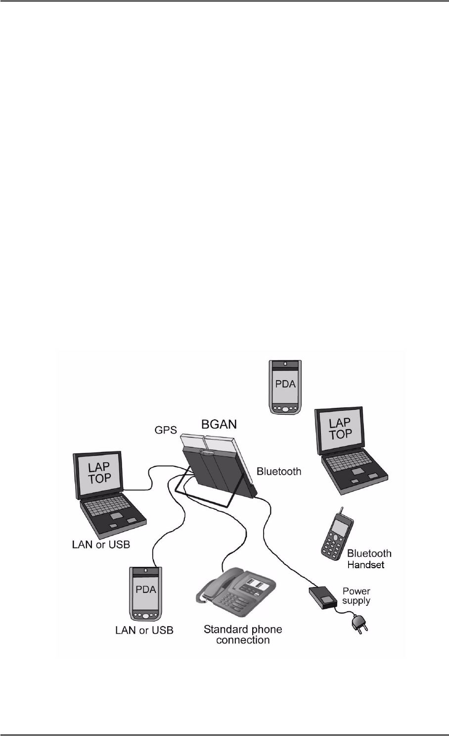
The EXPLORER™ 500 is a broadband mobile terminal with integrated antenna, providing
high-speed data and voice communication via satellite through the Broadband Global Area
Network (BGAN).
Just plug in a phone, fax, laptop or PDA, or use the Bluetooth® interface, point the antenna
towards the BGAN satellite - and you are online.
The flat, light-weight design of the EXPLORER™ 500 makes it easy to carry e.g. in the front
pocket of a laptop bag.
Applications include:
• High-speed data access
• Phone and fax services
• Large file transfers
• Video conferencing and streaming
• Internet browsing
•Email
• VPN access to corporate servers
In This Chapter
This chapter gives an overview of the BGAN system and services, and introduces the
EXPLORER™ 500.
It also gives an overview of the physical unit and its features and functions.

Chapter 1: Introduction
TT 98-122274-E 1-2
The BGAN System
What is BGAN?
The Broadband Global Area Network (BGAN) is a mobile satellite service that offers high-
speed data (up to 492 kbps) and voice telephony. BGAN enables users to access e-mail,
corporate networks and the Internet, transfer files and make telephone calls.
Coverage
The Inmarsat® BGAN services are based on geostationary satellites situated above the
equator. Each satellite covers a certain area (footprint). The coverage map below shows the
footprints of the BGAN system.
Inmarsat plans to launch a third satellite, F3, at a later stage, extending BGAN satellite
coverage to virtually the entire surface of the earth.
Note The actual ability to obtain BGAN service in the coverage area depends on a
number of factors, such as unobstructed view to the satellite, licensing conditions
etc.
The map depicts Inmarsat's expectations of coverage
but does not represent a guarantee of service. The
availability of service at the edge of coverage areas
fluctuate depending upon a variety of conditions.
30°
20°
10°
0°
40°
50°
60°
70°
80°
90°
10°
20°
30°
40°
50°
60°
70°
80°
90°
0°20°40°60°80°100°120°140°160°180° 20° 40° 60° 80° 100° 120° 140° 160° 180°
53°W
AOR-W
64°E
IOR
F1 I-4 Satellite
F2 I-4 Satellite
(service coverage planned from 2006)
Chapter 1: Introduction
TT 98-122274-E 1-3
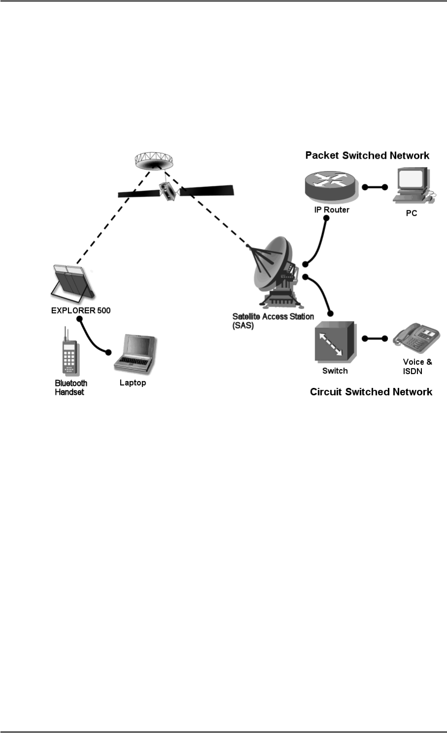
Overview of the BGAN System
A complete BGAN system includes the EXPLORER™ 500 with connected peripherals, the
BGAN satellite, and the Satellite Access Station (SAS). The satellites are the connection
between your terminal and the SAS, which is the gateway to the worldwide networks
(Internet, telephone network, cellular network, etc.).

Chapter 1: Introduction
TT 98-122274-E 1-4
The BGAN Services
Supported Services
The services currently supported by BGAN comprise:
• IP connection to the Internet
• Dialled connection for voice, fax or data
• Short Messaging Service (SMS)
IP Service
The BGAN network supports different classes of data connection to the Internet.
• Using a Standard data connection, several users can share the data connection
simultaneously. This type of connection is ideal for e-mail, file transfer, and internet and
intranet access.
The user pays for the amount of data sent and received (per MB charge).
• Using a Streaming data connection, you get an exclusive, high-priority connection,
ensuring seamless transfer of data. This type of connection is ideal for time critical
applications like live video over IP.
The user pays for the duration of the connection (per minute charge).
Dialled Service
Two types of voice connection are available:
•Standard voice: A low-tariff connection for voice only. The voice signal is compressed
to 4.0 kbps, which reduces the bandwidth use and subsequently the tariff.
•Premium voice: A high quality connection which can be used for voice, G.3 fax or
PSTN modem.
The signal is uncompressed 3.1 kHz audio, which allows for optimum voice quality.
SMS Service
The BGAN system provides a Short Messaging Service (SMS) for sending and receiving
SMS messages.
Supplementary Services
The BGAN system also provides the following Supplementary services:
• Call barring
• Call hold
• Call waiting
• Call forwarding
•Voice mail
Chapter 1: Introduction
TT 98-122274-E 1-5
Overview of the EXPLORER™ 500
Features
The EXPLORER™ 500 provides the following features:
High speed data up to 464 kbps - shared bandwidth
Support for streaming classes 32, 64 and 128 kbps
Simultaneous voice and data
Standard interfaces (LAN, USB, Bluetooth and phone/fax)
Lightweight and portable design
Easy setup and use
Robust and durable design
Overview of Interfaces
The EXPLORER™ 500 provides a number of interfaces for connection of data equipment,
fax devices and phones.
Using the Interfaces on page 4-1 describes how to use each of the available interfaces.
Chapter 1: Introduction
TT 98-122274-E 1-6
Power Saving
The EXPLORER™ 500 is designed to save power. This means that functions that are not
currently used will automatically go into a “sleep mode” to save power.
In addition to the automatic power saving, you can turn each of the interfaces off if they are
not currently used. Note, however, that you will not be able to use these interfaces until you
turn them back on. For information on how to turn interfaces on and off, see Turning an
Interface on or off on page 4-3.
Your EXPLORER™ 500
Overview
The EXPLORER™ 500 is a compact unit, comprising antenna, compass, display and
keypad, all in one unit.
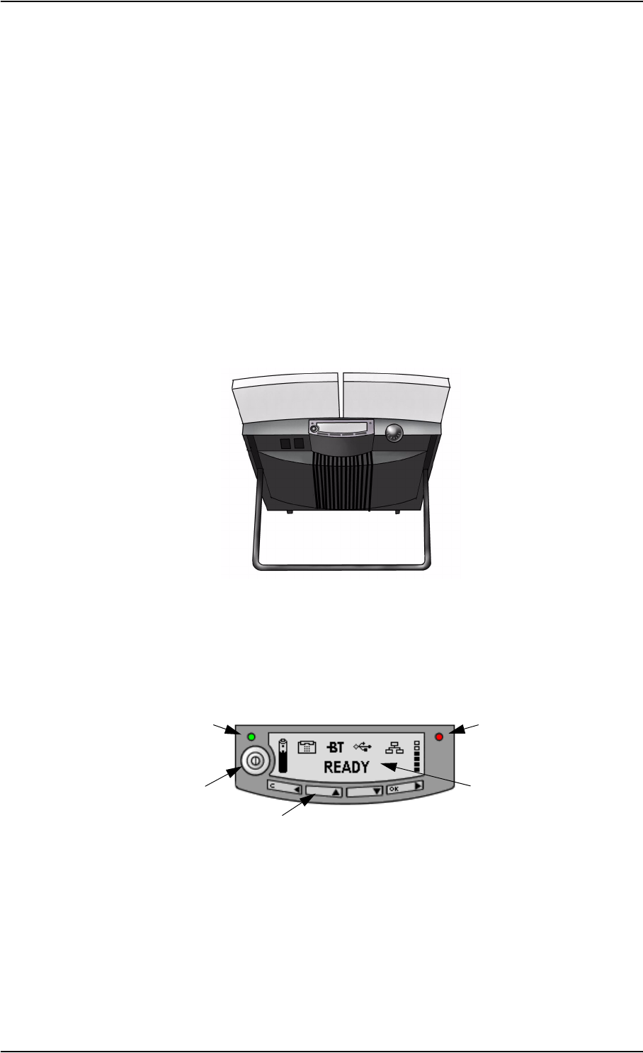
Display and Keypad
The EXPLORER™ 500 has a display and a keypad for displaying status and for changing
simple parameters.
For information on how to use the keypad and display, and for an overview of the display
menu system, see Using the Display and Keypad on page 3-1.
Power indicator
Power Button
Keypad
Display
Message indicator

Chapter 1: Introduction
TT 98-122274-E 1-7
Light Indicators
The EXPLORER™ 500 has two light indicators next to the display: a green power indicator
and a red message indicator.
Green Power Indicator
The function of the green Power indicator to the left of the display is as follows:
Red Message Indicator
The function of the red Message indicator is as follows:
Behaviour of Green
Indicator Meaning
Short flash every 2 seconds The EXPLORER™ 500 is on.
Steady light The battery is charging.
Flashing rapidly A charging error has occurred.
For further information, refer to Troubleshooting Guide
on page 6-4.
Off No power.
Behaviour of Red
Indicator Meaning
Flashing A message is present in the display.
Read the message and then acknowledge it by pressing
OK.
The red light will keep flashing after OK is pressed if:
• there are more messages, or
• the message is information of an error.
For information on error messages, see Error
Messages on page 6-10.
Off No messages are present.

Chapter 1: Introduction
TT 98-122274-E 1-8
User Interfaces
The keypad and display is used for pointing the antenna, for displaying status and for
changing simple parameters.
To obtain full access to all features and for ease-of-use, you should use a data unit (a PC,
Laptop, PDA or similar) and one of the following:
• The built-in Web interface. The EXPLORER™ 500 has a built-in Web interface for easy
configuration and daily use. The Web interface is accessed directly from a data unit
connected to the EXPLORER™ 500, using a standard Internet browser.
For information on the Web interface, see the chapter Using the Web Interface.
• The Inmarsat Launch Pad. Launch Pad is a PC application used to control terminals in
the BGAN system. Launch Pad is provided on the Inmarsat CD ROM supplied with your
EXPLORER™ 500. For information on how to use the Launch Pad, refer to the manual
on the Inmarsat CD ROM.
Additionally, it is possible to control the EXPLORER™ 500 using AT Commands. Refer to
the appendix AT Commands.
Antenna
The white part of the EXPLORER™ 500 is the antenna module. The antenna module
comprises a GPS antenna, a BGAN antenna and a Bluetooth antenna.
Compass
The EXPLORER™ 500 also provides a compass to help positioning
the antenna. For further information on how to use the compass, see
Pointing the Antenna on page 2-10.
Battery
The EXPLORER™ 500 comes with a rechargeable battery, which is easily inserted in the
terminal. The battery is automatically charged when power is applied to the
EXPLORER™ 500. Steady green light indicates that the battery is charging.
SIM Card
The SIM card of the EXPLORER™ 500 is a standard SIM card, which is acquired from the
Airtime provider.
The EXPLORER™ 500 requires a SIM card to go online and to access the settings of the
EXPLORER™ 500. Without a SIM card you can only see the Main screen of the display
system, showing battery status etc.

Chapter 1: Introduction
TT 98-122274-E 1-9
Matrix of Services and Communication Interfaces
The following table shows which services can be accessed from which interfaces, and which
types of equipment can be used.
What’s Next?
This chapter has provided an overview of the BGAN system and of the EXPLORER™ 500.
The next chapters will go into more detail about how to set up and use the
EXPLORER™ 500. The following chapter, Getting Started, explains how to unpack and
start up the EXPLORER™ 500, and how to point the antenna in order to get the best possible
signal.
Service
Interface on the EXPLORER™ 500
Phone/Fax Bluetooth USB LAN Display/
Keypad
Dialled Connection
Premium
voice
Analogue
telephone
Bluetooth
handset
G.3 Fax
machine
Standard
voice
Analogue
telephone
Bluetooth
handset
Data
Data unit with
modem
Data unit
with Soft
modem
IP Connection
Data
multi-
user
Data unit Data unit
with
Switch/Hub
Data
single-
user
Data unit Data unit Data unit
SMS Data unit Data unit Data unit View only

TT 98-122274-E 2-1
Chapter 2
Getting Started 2
In This Chapter
This chapter describes
• what is included in the delivery
• how to insert the battery and SIM card
• how to start up the EXPLORER™ 500 and make the first call
Unpacking and Assembling
Unpacking
Unpack the EXPLORER™ 500 and accessories.
Check that the following items are present:
Explorer 500 Terminal
With Built-in Antenna
LAN Cable
AC/DC Power Supply
Battery
Instruction Kit
Including:
- Getting Started
- Quick Guide
- Thrane & Thrane CD-ROM
- Inmarsat CD-ROM

Chapter 2: Getting Started
TT 98-122274-E 2-2
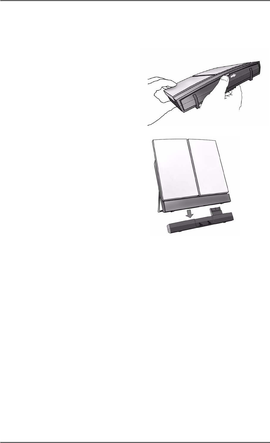
Inserting the SIM Card
The EXPLORER™ 500 normally comes with the battery separated from the user terminal. If
the battery is already inserted, remove it as described in Removing the Battery on page 2-3.
The SIM card is provided by your Airtime Provider. Insert the SIM card as follows:
1. Insert the SIM card into the SIM slot. Make
sure the SIM card is positioned as shown!
2. Press gently until it clicks.
3. Slide the lock to close the SIM slot.
Inserting the Battery
Do as follows:
1. Insert the battery.
Make sure the battery is positioned correctly
as shown.
2. Press gently until it locks.
Note Before using the EXPLORER™ 500 the first time, It is recommended to fully
charge the battery.
To charge the battery, insert it into the EXPLORER™ 500 and connect the
EXPLORER™ 500 to power.
The indicator left to the display is constantly green as long as the battery is
charging. When the battery is fully charged, the green indicator is turned off. If the
EXPLORER™ 500 is switched on, the green indicator will be flashing shortly
every 2 seconds.
Chapter 2: Getting Started
TT 98-122274-E 2-3
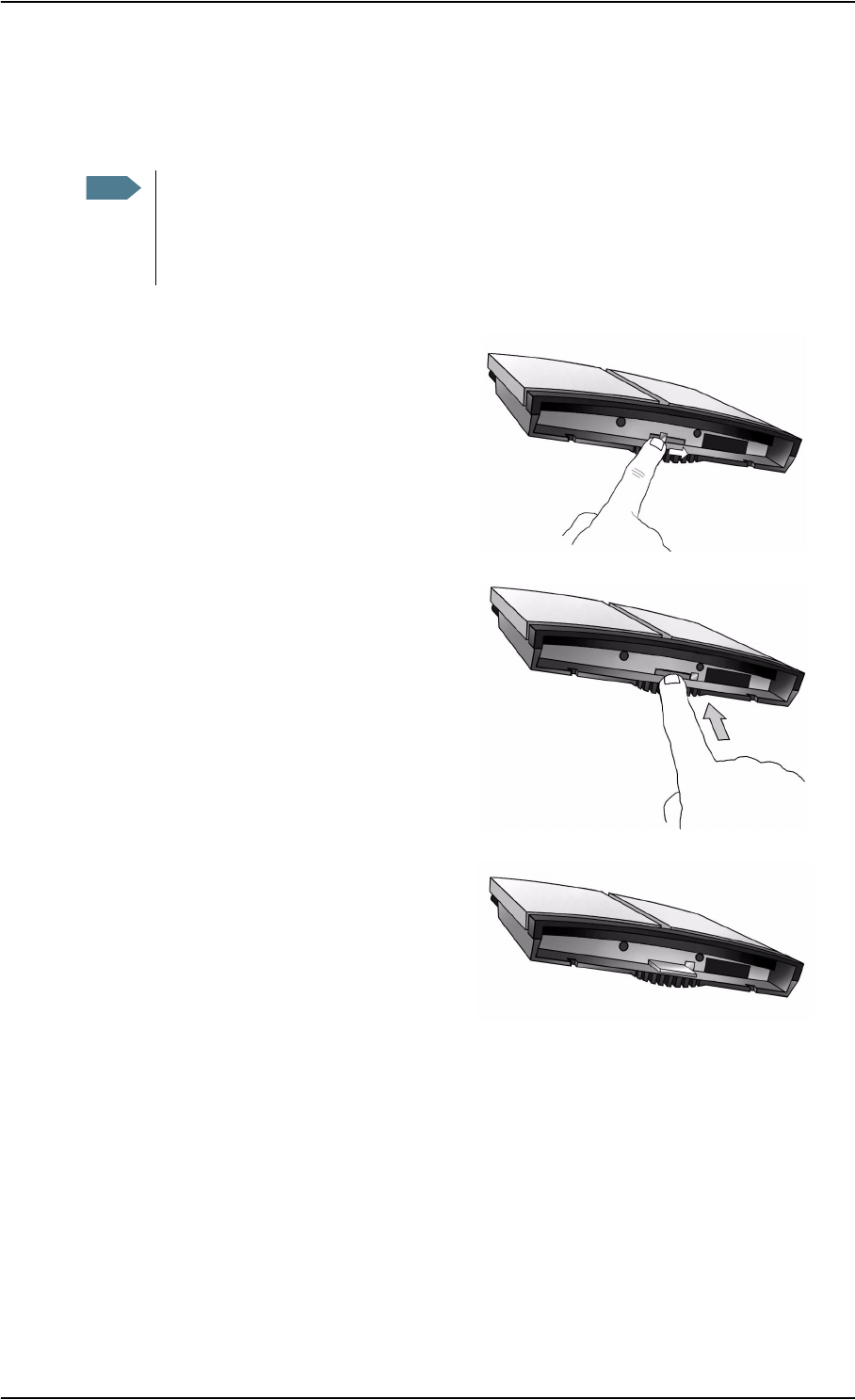
Removing the Battery
To remove the battery, do as follows:
1. Locate the slide lock at the bottom
of the unit.
2. Slide the lock aside to release the
battery from the unit.
3. Remove the battery.
Chapter 2: Getting Started
TT 98-122274-E 2-4
Removing the SIM Card
To remove the SIM card, first remove the battery as described in Removing the Battery on
page 2-3.
Remove the SIM card as follows:
1. Slide the lock aside to open the SIM
slot as shown.
2. Gently press the SIM card and let it
pop out of the slot.
3. Remove the SIM card.
Note When the SIM card is removed, you cannot use the display menu system nor make
calls or start data sessions.
Only emergency calls are allowed, and only if permitted by the network.
You can see the battery status and the signal strength in the display.

Chapter 2: Getting Started
TT 98-122274-E 2-5
Connecting Cables
After inserting SIM card and battery, connect all relevant cables.
For information on how to connect to a specific interface, see the corresponding section in
the chapter Using the Interfaces. However, connecting to power is described at the end of
this section.
Side Connector Panel
The connector panel is placed on the side of the EXPLORER™ 500 and has the following
connectors:
• USB connector for data equipment
• Phone/fax connector for phone, fax or
PSTN modem
• LAN connector for data equipment
• DC power connector (10-16 V DC) for
connection to a 115/230 V AC/DC
power supply or to a charger cable
which connects to the cigarette lighter
in a car.
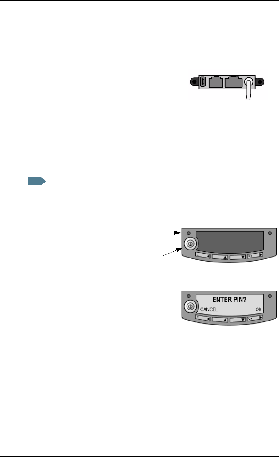
Rear Connectors
Apart from the connectors in the connector panel, the EXPLORER™ 500 has two connectors
placed on the rear side of the EXPLORER™ 500:
• a connector for the Thrane & Thrane
external antenna, marked ANT and
• a connector for charging the
EXPLORER™ 500 Bluetooth Handset,
marked DC OUT.
Before Connecting to Power
You can connect to power or use the battery delivered with your EXPLORER™ 500.
Refer to Power Input on page A-3 for specifications and pin-out for the DC power input.
If you are connecting to 115/230 V Mains, use the AC/DC power supply included with your
EXPLORER™ 500.
You may also connect directly to the cigarette lighter socket in a car. A suitable charger cable
is available from Thrane & Thrane.
Important Connect the cables before making the final adjustment of the antenna position.
Otherwise you may accidentally move the antenna when you connect the
cables.
USB Phone/fax DC PowerLAN
Chapter 2: Getting Started
TT 98-122274-E 2-6
Connecting to Power
You can connect the DC input to power without the battery inserted.
If the battery is inserted when you apply power to the EXPLORER™ 500, the battery is
automatically charged.
Connecting to 115/230 V Mains: Connect the AC/DC
power supply to the DC power input of the
EXPLORER™ 500. Then connect the power cable
between 115/230 V Mains and the AC/DC power supply.
Connecting to the cigarette lighter in a car: Connect the charger cable between the DC
power input of the EXPLORER™ 500 and the cigarette lighter socket in the car.
Powering the EXPLORER™ 500
Switching On the EXPLORER™ 500
To switch on the EXPLORER™ 500,
push the power button next to the
display and hold it down for a second
until the green Power indicator lights
up.
To switch off the EXPLORER™ 500, push the power button again and hold it for a second,
until the display shows “Switching off...”.
After switching on the EXPLORER™ 500 you will be
prompted for a PIN code, unless the PIN code is
disabled.
For information on how to disable the PIN code, see
Changing or Disabling the PIN Code on page 5-17.
For information on the options after power on, see the next section.
Note The default behaviour of the EXPLORER™ 500 is to power up automatically when
you connect the power cable. If you wish, you can change this power up mode, so
that the EXPLORER™ 500 is only powered if the power button is pressed.
For further information on power up mode, see Setting the Power up Mode on
page 3-10 or Power up Behaviour on page 5-11.
Power
Power
Indicator
Button
Chapter 2: Getting Started
TT 98-122274-E 2-7
Options for the Start-up Procedure
You have different options for the start-up procedure. Each of these options are briefly
described in this section.
For information on how to enter PIN code and point the antenna, see the subsequent sections.
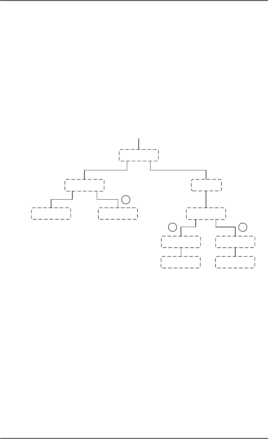
Overview of the Start-up Options
The following drawing shows the options available after power on. Note that if the use of
PIN code is disabled, the display sequence is the same as after successfully entering the PIN
code. This means that after power on, you will see the Signal strength screen.
1: “Full” Procedure
After power on, enter the PIN code and then point the antenna.
In this mode you have full access to the EXPLORER™ 500, that is you can use the menu
system and communicate on the BGAN network.
The display will show READY when the menu system is not activated.
Power on
ENTER PIN?
Cancel OK
ENTER PIN
*-
"Signal Strength"
Cancel OK
"Signal Strength"
Cancel OK
"Main screen" "Main screen"
You can access the
menu system but you
cannot use the BGAN
network.
You can access the
menu system and use
the BGAN network.
"Main screen"
You cannot access the
menu system, and you
cannot use the BGAN
network.
"Main screen"
You cannot access the
menu system, and you
cannot use the BGAN
network, except for
emergency calls, if
allowed by the network.
12
3
Menu system Menu system

Chapter 2: Getting Started
TT 98-122274-E 2-8
2: “Off-line” Procedure
After power on, enter the PIN code, but cancel pointing.
In this mode you can use the menu system, but are not able to communicate on the BGAN
network.
The display will show POINT NOW? when in the Main screen.
Press S or T to enter the menu system.
If you want to point the antenna later, press OK from the Main screen.
3: “Emergency” Procedure
After power on, cancel the PIN code and then point the antenna.
In this mode you can only place emergency calls, and only if permitted by the network. You
are not able to access the menu system nor to communicate on the BGAN network (apart
from emergency calls), until you enter the PIN code.
The display will show ENTER PIN?
If you press OK you can enter the PIN code. No other options are available from the keypad.
Chapter 2: Getting Started
TT 98-122274-E 2-9
Entering the PIN Code
Overview
You have to enter a PIN code to use the EXPLORER™ 500, unless the use of PIN codes is
disabled using the built-in Web interface of the EXPLORER™ 500 (see Disabling the PIN
Code on page 5-17).
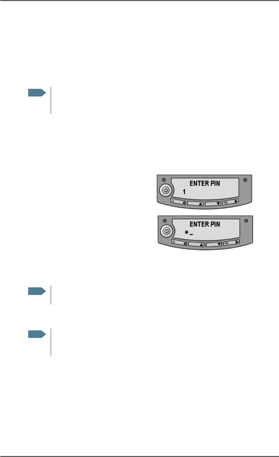
To Enter the PIN Code
To enter the PIN code using the display and keypad, do as follows:
1. When you are asked for a PIN code, press OK.
2. Press S or T a number of times until the
first digit is correct.
3. Press OK to go to the next digit.
When OK is pressed, the previous digit is
indicated by a *.
To correct an entered digit, press C to go back and use the S and T buttons again.
4. After entering the last digit with OK, press OK again to apply the PIN code.
For further information on how to use the keypad and display, see Using the Display and
Keypad on page 3-1.
Wrong PIN Code
You have 3 attempts to enter the PIN code, before you are asked to enter the PUK code. The
PUK code is supplied with your SIM card.
Enter the PUK code followed by a new PIN code of your own choice. The PIN code must be
from 4 to 8 digits long.
If you enter a wrong PUK code 10 times, the SIM card will no longer be functional, and you
have to contact your Airtime provider for a new SIM card.
Note The first time you are asked for a PIN code, you can choose to cancel (press C). If
you cancel, you are asked again after pointing is completed. At that point you must
enter the PIN code to be able to continue.
Note At this point the EXPLORER™ 500 may make a sound. This sound is used for
pointing the antenna. To turn off the pointing sound, press S or T.
Note You can enter the PIN code using a phone or data unit connected to the
EXPLORER™ 500. For further information, see Entering the PIN Code Using a
Phone on page 4-7 or Entering the PIN Code in the Web Interface on page 5-4.
Chapter 2: Getting Started
TT 98-122274-E 2-10
Pointing the Antenna
The Importance of Pointing
In order to obtain the best possible signal at the
lowest possible cost, it is important that the
EXPLORER™ 500 antenna is pointed
correctly towards the satellite.
Incorrect pointing may result in poor quality of
the signal, and in some cases retransmission
may be necessary, which could mean you will
be paying more than necessary for your
transmission.
The antenna must have a clear line of sight to
the satellite, without any obstacles blocking the
signal, and the pointing direction of the
antenna should be as accurate as possible.
The next sections describe how to point the antenna for the best possible signal.
Pointing Data
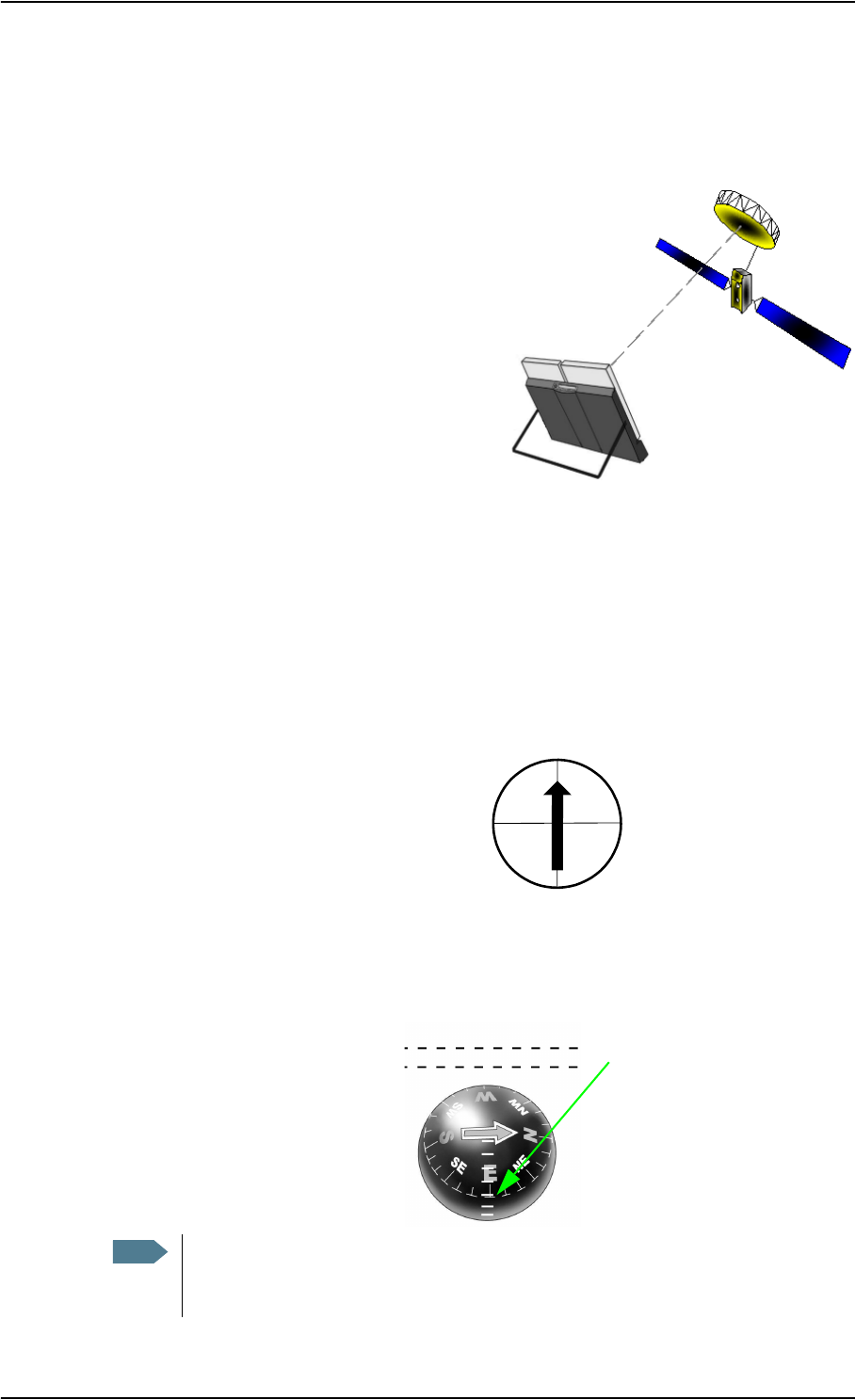
If the position of the satellite in relation to the EXPLORER™ 500 is known, you can use the
compass to roughly point the antenna in the right direction. If you know the Azimuth and the
Elevation, you can use this data to adjust the antenna.
•The Azimuth is the horizontal
rotation angle relative to North
(moving clockwise).
•The Elevation is the vertical rotation angle relative to horizontal. This means that an
Elevation of 0° corresponds to the terminal being in an upright position, pointing towards
the horizon.
The compass has 7 lines dividing the
Elevation scale into 6 spaces. The
space between two lines corresponds
to 15°.
Note The above explanation assumes that the compass shows the exact orientation.
Please take into consideration the possible deviation and variation that can occur,
e.g. because of the location or the presence of magnetic objects.
N = 0°
S = 180°
E = 90°W = 270°
This compass shows an
Elevation of 30°
The Elevation is measured
where the lines meet.
(2 spaces up from the first line)
and an Azimuth of 270°
(antenna pointing towards West)
Front of Terminal

Chapter 2: Getting Started
TT 98-122274-E 2-11
Minimum Signal Strength
The following table shows the minimum signal strength required for different types of
transmission.
Pointing the Antenna Towards the Satellite
Note These figures are only guidelines; they do not represent a guarantee of operation at
the stated signal strength. Also, these figures are yet to be confirmed in practice.
Type of Service Minimum Required Signal Strength
Standard Data 51 dBHz
Streaming 32 kbps 51 dBHz
Streaming 64 kbps 54 dBHz
Streaming 128 kbps 57 dBHz
Standard Voice 51 dBHz
Premium Voice TBD
Important When pointing the antenna, do not touch the white antenna part of the
EXPLORER™ 500. If you place your fingers on the antenna part, you will be
blocking the signal, and the antenna will not work properly.
You can hold the support bracket and the battery module below the antenna
while pointing the EXPLORER™ 500.
Chapter 2: Getting Started
TT 98-122274-E 2-12
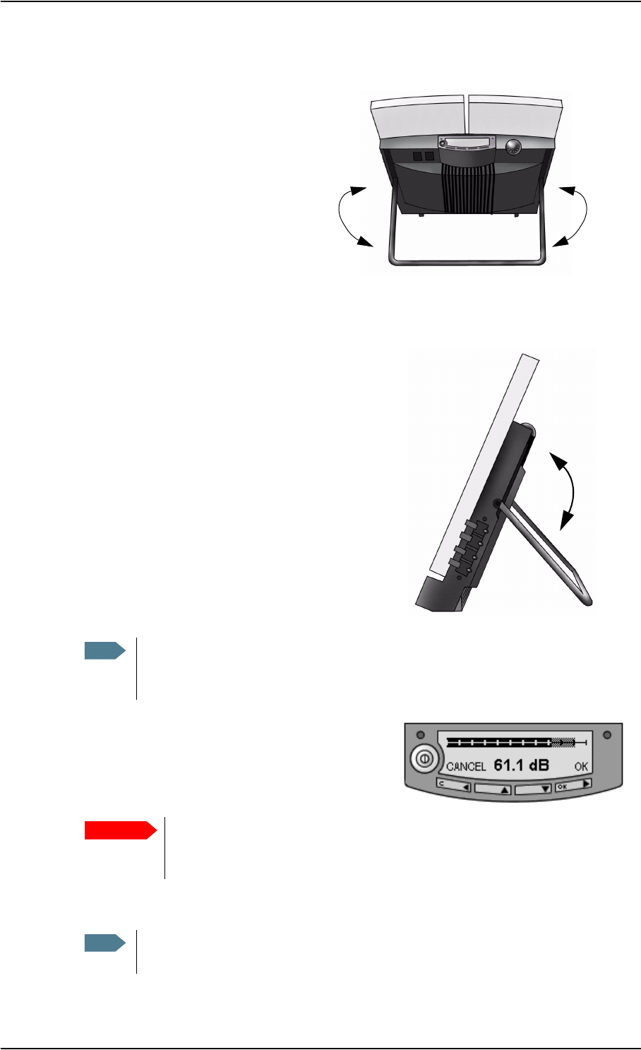
Do as follows to point the antenna:
1. While observing the built-in compass
of the EXPLORER™ 500, rotate the
EXPLORER™ 500 left or right until it
points in the correct horizontal
direction, known as the Azimuth.
Refer to Pointing Data on page 2-10.
2. Tilt the EXPLORER™ 500 slowly up or
down until it points in the correct vertical
direction, known as the Elevation. Refer to
Pointing Data on page 2-10.
3. After passing the PIN code screen, the display
shows the current satellite signal strength. Use
this information to fine-adjust the antenna
position as shown in step 1 and 2.
Remember not to touch the antenna part.
A sound also indicates the signal strength (if enabled). The frequency of the tone
increases with the signal strength. To turn off the pointing sound, press S or T.
Note Make sure all cables are connected before fine adjusting the antenna position. If
you connect cables after the final adjustment of the antenna position, you may
accidentally move the antenna.
Important When fine-adjusting the antenna, the display may take a while to update the
signal strength. Wait a while after each move, to make sure the display is
updated.
Note If the right most part of the signal strength bar is grey, it indicates that the level
has previously been higher than the current level.

Chapter 2: Getting Started
TT 98-122274-E 2-13
4. When you have obtained the highest possible
signal strength, press OK on the keypad.
The EXPLORER™ 500 now tries to
establish a connection to the BGAN network.
The display shows the progress as follows:
•SEARCHING: The EXPLORER™ 500 searches for the network operator. Note that
the search procedure can be very short, so you may not see this text.
•ATTACHING: The EXPLORER™ 500 is registering itself on the network.
•READY: The EXPLORER™ 500 is registered on the network and is ready to go
online.
Note The display may show a different text than READY if there is more important
information to show. For example, the display will show ENTER PIN? if you
pressed C at the first request for a PIN code.
Chapter 2: Getting Started
TT 98-122274-E 2-14
Using an External Antenna
The EXPLORER™ 500 has a connector for attaching an external antenna.
The connector is placed at the back of the EXPLORER™ 500. For further information on the
interface, see the technical specifications in External Antenna on page A-9.
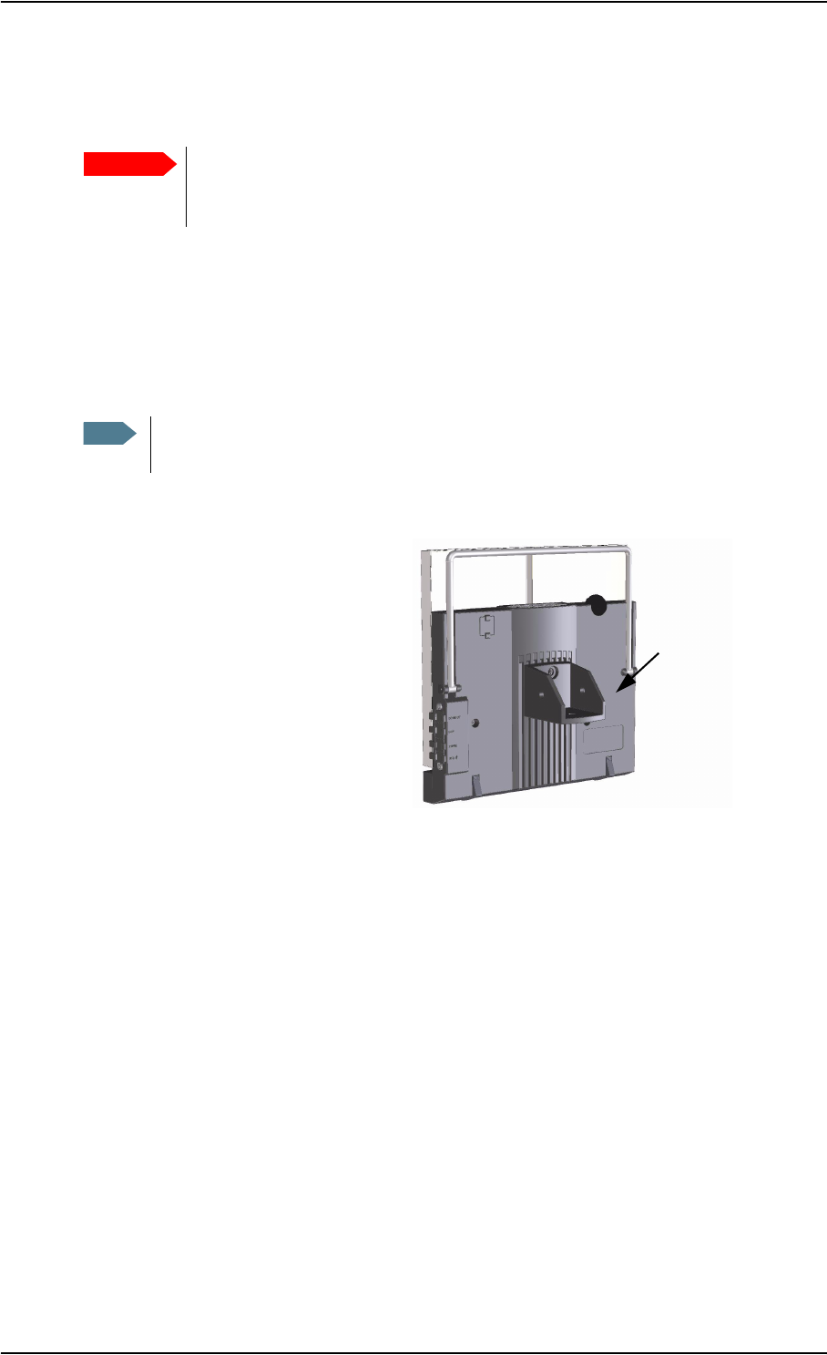
Using a Fixed EXPLORER™ 500
You can keep the EXPLORER™ 500 in a fixed position, using the pole mount option.
Do as follows:
1. Mount the Pole Mount bracket on
the EXPLORER™ 500 as shown.
2. Mount the EXPLORER™ 500 on a pole.
3. Start up the EXPLORER™ 500 and point the antenna as described in Pointing the
Antenna Towards the Satellite on page 2-11.
4. Accept the signal strength by pressing OK on the EXPLORER™ 500 keypad.
You only have to point the antenna once, when you mount it. Using a PC connected to the
EXPLORER™ 500, you can set up the EXPLORER™ 500 to skip pointing at next power
up. Refer to Pointing at Power up on page 5-11.
Important Only use the specified antenna from Thrane & Thrane. The antenna and
accessories for connecting to the EXPLORER™ 500 are listed in Options and
Accessories on page 6-2.
Note The EXPLORER™ 500 is not suited for permanent outdoor installation. Use an
external antenna if the installation is to be permanent.
Pole Mount bracket

Chapter 2: Getting Started
TT 98-122274-E 2-15
Making the First Call
After connecting cables, entering the PIN code and pointing the antenna, you are ready to
make or receive the first call.
The following sections provide a short guide to making calls. For more detailed information,
see Making or Receiving a Phone Call With the EXPLORER™ 500 on page 4-8.
Making a Call From the EXPLORER™ 500
If you are using an analogue phone, it must be connected to the phone/fax interface of the
EXPLORER™ 500. See Before Connecting to the Phone/Fax Interface on page 4-6.
If you are using a Bluetooth handset, the Bluetooth handset and the EXPLORER™ 500 must
be paired and connected before you can make a call. See Handling Bluetooth Device Access
on page 4-17.
To make a call from a phone connected to the EXPLORER™ 500, dial:
00 <country code> <phone number> followed by # or off-hook key (# on analogue phones,
off-hook key on Bluetooth handsets).
Example: To call Thrane & Thrane in Denmark (+45 39558800) from an analogue phone,
dial: 00 45 39558800 #
Making a Call to the EXPLORER™ 500
To make a call to a phone connected to the EXPLORER™ 500, dial:
+870 <Mobile number>
•+ is the prefix used in front of the country code for international calls. This is 00 when
calling from countries in Europe and from many other countries.
•Mobile number: The mobile number of the EXPLORER™ 500 you are calling.
The mobile numbers of the EXPLORER™ 500 are listed in the display menu system of
the EXPLORER™ 500 under PROPERTIES > MOBILE NUMBERS.
Example: If you are calling from Denmark and the terminal’s Mobile number for Premium
voice is 772112345, and you want to make a call to the terminal using Premium voice, dial:
00 870 772112345
Making a Call from one EXPLORER™ 500 to Another EXPLORER™ 500
To make a call from a phone connected to one EXPLORER™ 500 to a phone connected to
another EXPLORER™ 500, dial 00 870 <Mobile number>.
Note There are two voice numbers, one for Premium voice and one for Standard voice.

Chapter 2: Getting Started
TT 98-122274-E 2-16
Receiving a Call
To be able to receive a call with an analogue phone, the phone must be connected to the
Phone/fax interface of the EXPLORER™ 500.
To be able to receive a call with a Bluetooth handset, the handset must be paired with the
EXPLORER™ 500. For information on how to pair Bluetooth devices, see Handling
Bluetooth Device Access on page 4-17.
Information of unanswered calls is stored in the call log of the EXPLORER™ 500.
Making the First Data Connection (LAN)
Do as follows:
1. Connect the LAN cable to the network interface of your data unit.
A suitable cable is provided with your EXPLORER™ 500.
2. Connect the other end of the cable to the
LAN connector on the EXPLORER™ 500.
3. Start up and point the EXPLORER™ 500 as described earlier in this chapter.
4. Power on the data unit.
5. When power up and pointing is completed, check the connection, e.g. by starting your
Internet Browser.
What’s Next?
After reading this chapter you should be able to start up the EXPLORER™ 500 and make a
simple data or voice connection.
The next chapters provide more information on the user interfaces and the setup of the
EXPLORER™ 500. The following chapter, Using the Display and Keypad, explains the
display menu system, which is the basic tool for setting up the EXPLORER™ 500.
Note For the LAN interface to work without any further setup, the data unit must be set
up to obtain an IP address and a DNS server address automatically. To check these
settings on your data unit, do as follows:
For Windows® XP (Classic Start menu), expand the Start menu and select
Settings > Network Connections > Local Area Connection.
Then select Internet Protocol (TCP/IP) and click Properties.
Make sure both fields are set to obtain an address automatically.
Note You may have to disable the Proxy server settings in your browser. For further
information, see Browser Settings on page 5-2.

TT 98-122274-E 3-1
Chapter 3
Using the Display and Keypad 3
In This Chapter
This chapter describes how to use the built-in display menu system of the
EXPLORER™ 500.
It contains an overview of the entire menu system followed by a description of each menu.
It also explains the symbols and messages that may appear in the display, and describes how
to navigate using the keypad.
Menu Overview
Main Menu
The items of the main menu are:
•Messages
shows all incoming SMS messages and allows you to open or delete each message or
delete all messages.
•Calls
shows missed, received and outgoing calls.
•Settings
allows you to restart the pointing procedure, set display brightness and contrast, set audio
indications on or off, turn each interface on or off, enable or disable stealth mode (a
terminal mode where lights and sound are off), set the power up mode and restore
settings.
•Properties
shows which Bluetooth devices are known and accepted, and shows IP address, hardware
and software numbers, IMEI number and mobile numbers. It also shows the alarm list and
the GPS status.
•Help Desk
shows the phone number to the airtime provider.
For information on how to navigate in the menu system, see Navigating the Display and
Keypad on page 3-5.

Chapter 3: Using the Display and Keypad
TT 98-122274-E 3-2
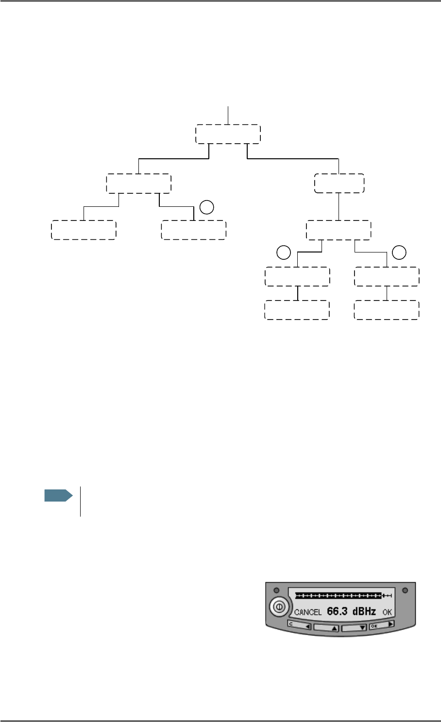
Menu Drawing
The below drawing shows an overview of the menus in the display menu system of the
EXPLORER™ 500.
The next section shows an overview of the start-up sequence before entering the menu
system, and the menus are further described in the following sections of this chapter.
BLUETOOTH DEVICES
GPS STATUS
TERMINAL
MOBILE NUMBERS
VOICE MAIL NUMBER
ALARM LIST
<message 1>
<message 2>
<message 3>
<message 4>
DELETE ALL
MESSAGES
CALLS
SETTINGS
PROPERTIES
HELP DESK
MISSED
RECEIVED
OUTGOING
POINT NOW
DISPLAY
AUDIO INDICATOR
INTERFACES
STEALTH MODE
POWER UP MODE
RESTORE SETTINGS
2 SECONDS
5 SECONDS
10 SECONDS
30 SECONDS
60 SECONDS
LEVEL 1
LEVEL 2
LEVEL 3
LEVEL 4
LEVEL 5
LEVEL 6
LEVEL 7
1 <device>
2 <device>
3 <device>
4 <device>
5 <device>
6 <device>
7 <device>
IP ADDRESS
HARDWARE
SOFTWARE
IMEI
ON
OFF
TIMED
SET LEVEL
OPEN
DELETE MESSAGE
AUTOMATIC
SET LEVEL
LEVEL 1
LEVEL 2
LEVEL 3
LEVEL 4
LEVEL 5
LEVEL 6
LEVEL 7
POINTING
MESSAGES
WARNING
ALARM ON
OFF
PHONE/FAX
BLUETOOTH
LAN
ENABLED
DISABLED
AUTOMATIC
MANUAL
PIN Code
Start up
BRIGHTNESS
CONTRAST
ON
OFF
UNIT SER. NO.
MAIN PCB NO.
PSM PCB NO.
(Pointing)
Chapter 3: Using the Display and Keypad
TT 98-122274-E 3-3
Display Sequence at Start-up
There are different options for the start-up procedure. The below drawing shows the different
sequences.
The complete startup procedure is described in the chapter Getting Started.
This section only describes the behaviour of the display during startup.
PIN Code
Just after powering up the EXPLORER™ 500 you are asked if you want to enter the PIN
code. You can press OK and enter the PIN code, or you can press C and wait until you are
asked again after pointing.
After entering the PIN code or pressing C to skip, you enter the pointing screen.
Pointing
The Pointing screen shows the signal strength.
CANCEL: If you press C, you exit the pointing menu and the display shows the Main screen
with the message POINT NOW?.
Power on
ENTER PIN?
Cancel OK
ENTER PIN
*-
"Signal Strength"
Cancel OK
"Signal Strength"
Cancel OK
"Main screen" "Main screen"
You can access the
menu system but you
cannot use the BGAN
network.
You can access the
menu system and use
the BGAN network.
"Main screen"
You cannot access the
menu system, and you
cannot use the BGAN
network.
"Main screen"
You cannot access the
menu system, and you
cannot use the BGAN
network, except for
emergency calls, if
allowed by the network.
12
3
Menu system Menu system
Note Until you enter the PIN code, you will not be able to enter the menu system nor to
communicate on the BGAN network.

Chapter 3: Using the Display and Keypad
TT 98-122274-E 3-4
If the PIN code has been entered, you now have access to the menu system, but you will not
be able to connect to the BGAN network, because the signal strength has not yet been
accepted.
OK: When you press OK, the EXPLORER™ 500 tries to establish a connection to the
BGAN network.
The display shows the progress in the Main screen as follows:
•SEARCHING: The EXPLORER™ 500 is searching for the network operator.
•ATTACHING: The EXPLORER™ 500 is registering itself on the BGAN network.
•READY: The EXPLORER™ 500 is registered on the network and is ready to go online.
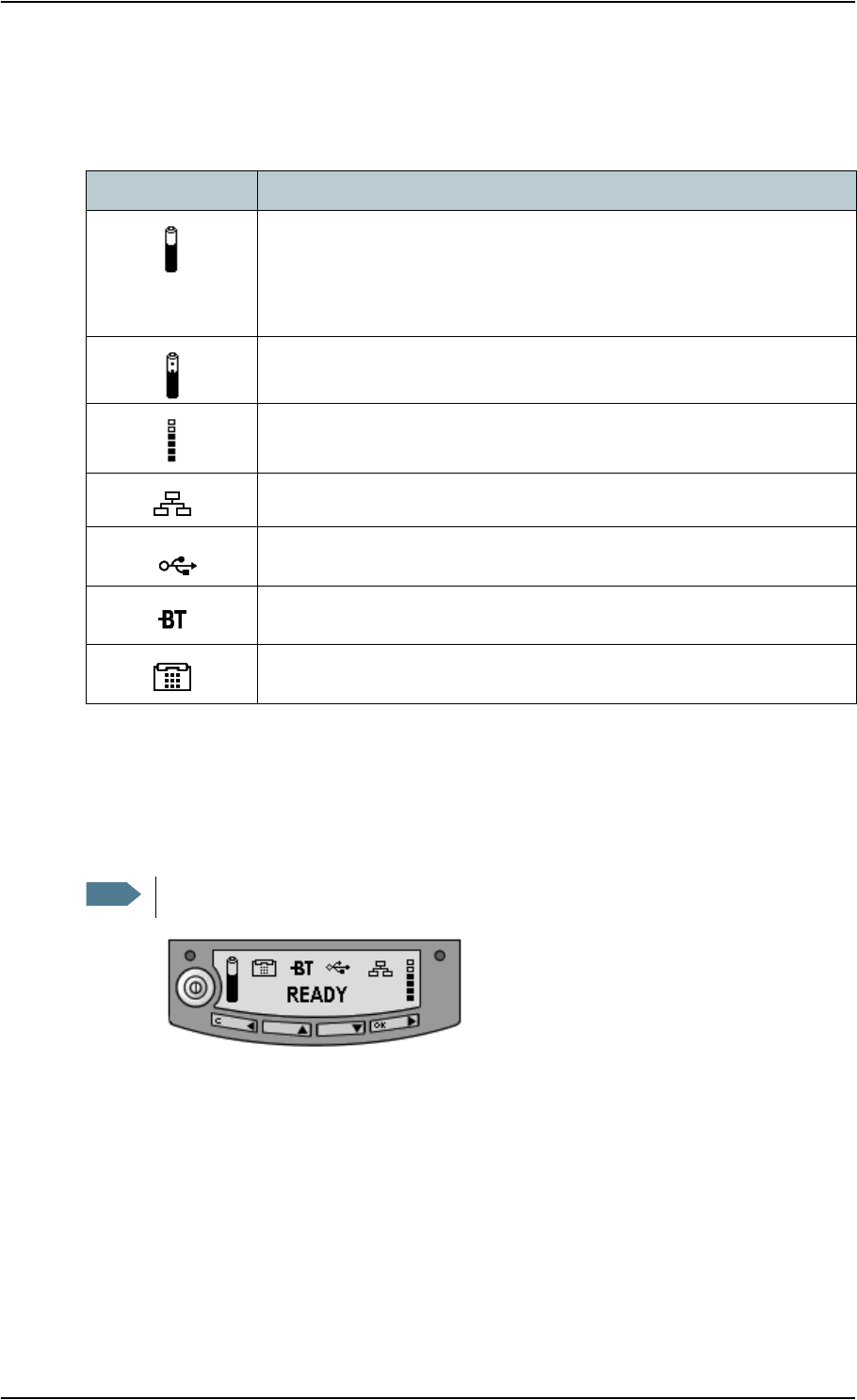
Main Screen
The Main screen is shown after passing the PIN code and pointing screens, and anytime you
leave the menu system.
The Main screen shows the most important status of the EXPLORER™ 500, such as battery
status, signal strength, and general status.
The Main screen also shows icons for any
interfaces that are turned on. In this example, all
interfaces (Phone/fax, Bluetooth, USB and LAN)
are turned on.
Chapter 3: Using the Display and Keypad
TT 98-122274-E 3-5
Display Symbols
Apart from the menu text, the display can show various symbols. Below is a list of the
possible symbols with an explanation to each symbol.
Navigating the Display and Keypad
Navigating with the Keypad
•To access the menu system from the Main screen,
press S or T.
•To move up and down in the current menu,
press S or T.
•To select the current menu item or setting,
press OK.
•To escape the current menu/setting and return to the previous level, press C.
•To see the hidden part of long text strings, press X.
Symbol Explanation
The battery charge level.
When the level is too low (below 10%) the icon flashes. Recharge the
battery as soon as possible.
If no battery is inserted, the symbol is not shown in the display.
The battery is charging.
The signal strength.
Minimum one bar is required to be able to make a Standard voice call.
LAN interface is on.
USB interface is on.
Bluetooth interface is on.
Phone/fax interface is on.
Note The PIN code must be entered before you can access the menu system.

Chapter 3: Using the Display and Keypad
TT 98-122274-E 3-6
•To move backwards in the menu system, or in long text strings, press W.
•To adjust settings, press S and T.
Short-Cuts
The following short-cuts are available in the menu system:
•To exit the menu system, press and hold C for one second. The display returns to the
Main screen.
•To activate/deactivate Stealth mode, Press C+OK.1
When stealth mode is activated, the display shows STEALTH ACTIVATED for a
moment; then all lights and sounds are turned off.
•To turn Pointing sound on/off, Press S or T from the pointing screen.
Display Text
When you have not entered the menu system, the Main screen shows the currently most
important information. For further information, see Text Information in the Display on
page 3-13.
CANCEL in the left side of the display means: Press C to cancel the current operation.
OK in the right side of the display means: Press OK to accept the current operation.
1. C+OK means: Press C and hold it while pressing OK.
Note For Stealth mode to be available, it must be enabled in the EXPLORER™ 500.
Refer to Enabling or Disabling Stealth Mode on page 3-9.
Note This action only applies to the current pointing session. To turn the sound on or
off for all pointing sessions, select
SETTINGS > AUDIO INDICATORS > POINTING and select ON or OFF.

Chapter 3: Using the Display and Keypad
TT 98-122274-E 3-7
The Menus
The following sections describe each of the menus in the menu system.
All available settings and status items are explained.
To access the menu system from the
main screen, press S or T.
Messages Menu
Viewing the List of Messages
To see the list of SMS messages, enter the menu system and select MESSAGES. The
messages are listed with the name (if known) or the number of the sender.
An unopened envelope indicates an unread message and an opened envelope indicates a read
message.
Use S and T to scroll through the list.
Opening or Deleting Received SMS Messages
In the MESSAGES list, select the message you want to open or delete and press OK. Then
select one of the following:
•OPEN to open the selected message.
The display shows the time and the message contents. Use S and T to scroll through the
message and details.
•DELETE to delete the selected message.
To delete all messages, go to the bottom of the list of messages and select DELETE ALL.
Calls Menu
To see a list of calls, select CALLS and then one of the following:
•MISSED to see a list of incoming calls that were not answered
•RECEIVED to see a list of incoming calls that were answered
•OUTGOING to see a list of outgoing calls
Select a call from the list to see details, such as time, date and phone number.
When there are more than 100 calls in the list, the oldest calls are automatically deleted to
make room for new calls.
Note Local calls are not registered.

Chapter 3: Using the Display and Keypad
TT 98-122274-E 3-8
Settings Menu
Point Now
If you need to repoint the antenna after the first pointing process, select SETTINGS >
POINT NOW.
This will bring you to the Pointing screen. See Display Sequence at Start-up on page 3-3,
where the pointing screen is described.
Setting the Display Brightness
To adjust the brightness of the display, select
SETTINGS > DISPLAY > BRIGHTNESS.
From this menu you can set the brightness of the display. Select one of the following:
•ON to turn the light on
•OFF to turn the light off
•TIMED to set how long the light should be on after the last key was psressed (2, 5, 10, 30
or 60 seconds)
•SET LEVEL to set the level of brightness
Setting the Display Contrast
To adjust the contrast of the display, select
SETTINGS > DISPLAY > CONTRAST.
From this menu you can set the contrast of the display. Select one of the following:
•SET LEVEL to set the contrast manually
•AUTOMATIC to let the EXPLORER™ 500 automatically adjust the contrast according to
the temperature.
Important This function will cause interruption of any ongoing calls or sessions!

Chapter 3: Using the Display and Keypad
TT 98-122274-E 3-9
Turning Audio Indicators On or Off
The EXPLORER™ 500 can make a sound to indicate an event.
You can turn each of these audio indicators on or off.
Select SETTINGS > AUDIO INDICATOR and select one of the following:
•POINTING - sound to indicate the signal level during pointing
•MESSAGES - sound to indicate that a message has arrived
•WARNING - sound to indicate that a warning is present
•ALARM - sound to indicate that an alarm is present
Then select ON or OFF.
Turning Interfaces On or Off
Each interface (except USB) can be turned off to save power.
Specially if the EXPLORER™ 500 is battery powered, it is a good idea to save power by
turning unused interfaces off.
To turn an interface on or off, select SETTINGS > INTERFACES and select one of the
following interfaces:
• BLUETOOTH
• PHONE/FAX
• LAN
Then select ON or OFF.
Enabling or Disabling Stealth Mode
In certain situations it may be important that the EXPLORER™ 500 is not seen nor heard.
When the EXPLORER™ 500 is in stealth mode, all lights and sounds are turned off. You
can still use the terminal, and the display text is readable.
To enable or disable the use of stealth mode, select
SETTINGS > STEALTH MODE and select one of the following:
• ENABLED
•DISABLED
To activate Stealth mode (after enabling Stealth mode),
press C+OK on the keypad.
To deactivate Stealth mode, press C+OK again.
Note Enabling stealth mode will not put the terminal into stealth mode, it only enables the
use of stealth mode.

Chapter 3: Using the Display and Keypad
TT 98-122274-E 3-10
Setting the Power up Mode
As default, the EXPLORER™ 500 starts up automatically when you apply external power.
You can change this mode, so that you always have to press the power button to switch on
the EXPLORER™ 500.
To set the power up mode, select
SETTINGS > POWER UP MODE and select one of the following:
•AUTOMATIC to have the EXPLORER™ 500 power up automatically when external
power is applied.
•MANUAL to have the EXPLORER™ 500 power up only when the power button is
pressed.
Restoring Settings
You can restore the settings made with keypad and display to default settings. Note,
however, that the display contrast remains as is.
To restore settings, select SETTINGS > RESTORE SETTINGS. Then press OK.
Important Be careful - this function will overwrite all your settings from the display/
keypad, except display contrast!
Chapter 3: Using the Display and Keypad
TT 98-122274-E 3-11
Properties Menu
Viewing Known Bluetooth Devices
You can view a list of the Bluetooth devices that have been accepted by the
EXPLORER™ 500. The devices are listed with their Bluetooth name and local phone
number.
The devices in this list can communicate with the EXPLORER™ 500 without any further
setup.
To view the list of known Bluetooth devices, select
PROPERTIES > BLUETOOTH DEVICES.
The devices are listed in the same order they were paired.
To see details on a specific Bluetooth device, select the device in the list and press OK.
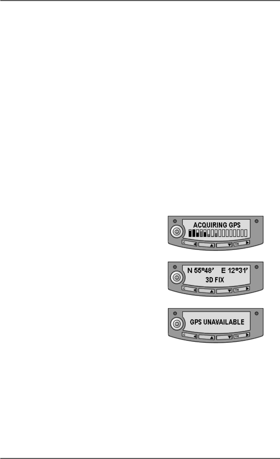
Viewing the GPS Status
The display can show the current GPS status.
To view the GPS status, select
PROPERTIES > GPS STATUS
The GPS status screen can vary, depending on the situation.
• If the GPS position has not yet been obtained,
the display shows the status of each of the 16
GPS satellites as follows:
• If the GPS position is known, the display
shows the GPS position, and whether it is a 2-
dimensional or 3-dimensional position (2D fix
or 3D fix).
• In some cases, the Satellite Access Station
does not allow the position to be displayed to
the user. If this is the case, the display shows
GPS UNAVAILABLE.

Chapter 3: Using the Display and Keypad
TT 98-122274-E 3-12
Viewing Terminal Properties
You can view properties of the EXPLORER™ 500, such as IP address, hardware numbers,
software version and IMEI number. When contacting Support, please include these numbers.
To view the properties, select PROPERTIES > TERMINAL and select one of the following
options:
•IP ADDRESS to see the IP address of the built-in Web interface of the
EXPLORER™ 500. The Web interface is a built-in web server used to configure and set
up the EXPLORER™ 500. For further information on the Web interface, see Using the
Web Interface on page 5-1.
•HARDWARE to see the serial number and PCB numbers of your EXPLORER™ 500.
•SOFTWARE to see the software version of the EXPLORER™ 500.
•IMEI to see the IMEI number (International Mobile Equipment Identity) of the
EXPLORER™ 500. This is the unique mobile equipment number that identifies your
EXPLORER™ 500.
Viewing Mobile Numbers
The MOBILE NUMBERS menu lists the mobile numbers to use when calling the
EXPLORER™ 500.
To view the mobile numbers, select
PROPERTIES > MOBILE NUMBERS.
Viewing the Voice Mail Number
The EXPLORER™ 500 informs you of any incoming voice mail through the display and
through the Web interface.
The Voice mail service number is the number you call to hear your incoming voice mail.
The Voice mail service number is stored on the SIM card.
To view the voice mail number, select
PROPERTIES > VOICE MAIL NUMBER.
Alarm List
If an error is present in the system, an alarm will be issued.
When an alarm is issued, the display shows that there is an active alarm and the red indicator
next to the display is flashing. If you press OK, the display returns to the Main screen, with
the text VIEW ALARM LIST? If you press OK again, the list of currently active alarms
appears.
You can always view the list of currently active alarms by entering the menu system and
selecting PROPERTIES > ALARM LIST.
For further information on alarms, see Error Messages on page 6-10.
Note There are two voice numbers, one for Premium voice and one for Standard voice.
For further information, see Selecting the Voice Quality on page 4-4.

Chapter 3: Using the Display and Keypad
TT 98-122274-E 3-13
Help Desk
If you need support regarding airtime, you may call the Airtime Provider help desk.
To see the Help Desk number, select HELP DESK in the menu system.
The display will show the name and phone number of your airtime provider, if it is available
on the SIM card.
If the information is not available on the SIM card, you can use the built-in Web interface of
the EXPLORER™ 500 to store the help desk name and number. For further information, see
Accessing the Help Desk on page 5-19.
Displaying Ongoing Transmission
Calls or Data sessions
When a call or data session is in progress, the display shows TRANSMITTING in the Main
screen.
Text Information in the Display
Types of Display Information
Text in the display can be:
• Information of received messages.
•Alarms.
• Status information.
• Request for action.
Received Messages
When messages arrive in your EXPLORER™ 500, the display indicates the number of new
messages that have arrived.The messages can be SMS messages or notification of Voice
mail.
• If the message is an SMS message, you can go directly to the message list by pressing
OK.
• If the message is information of Voice mail, you can press OK or C to go back to the
Main screen. The red message indicator will keep flashing until you have collected your
Voice mail.
To hear your Voice mail, call the Voice mail service number provided by your Airtime
Provider.
WARNING! When the display shows TRANSMITTING, stay clear of the
antenna front! The antenna emits radio frequency energy when transmitting.
Keep a minimum distance of 0.6 m from the antenna front.

Chapter 3: Using the Display and Keypad
TT 98-122274-E 3-14
To see the Voice mail service number, select
PROPERTIES > VOICE MAIL NUMBER
Alarms
When an alarm message appears in the display, you can press OK to remove it and go back
to the Main screen. However, you have not removed the cause of the alarm.
As long as the cause of the alarm is still present, the Main screen will show LIST ALARMS?
and the red indicator next to the display will be flashing.
To view the Alarm List, press OK. The alarm list shows any alarms that are currently active.
To see the name and the code of an alarm, select it from the list.
To view explanations for any alarms that may appear in the display, refer to the list of Cause
codes in Error Messages on page 6-10.
Status Information
Status information in the display is normally shown in the lower line of the Main screen.
Examples of status information are: READY, ATTACHING, TRANSMITTING.
Request for Action
A request for action, if it is not an alarm, is shown in the lower line of the display. This could
be e.g. POINT NOW? or INSERT SIM.
When the text is a question, press OK to accept.
What’s Next?
This chapter has explained how to navigate in the display menu system and how to use it for
basic setup of the EXPLORER™ 500.
The following chapter, Using the Interfaces, explains in detail how to set up and use each
interface of the EXPLORER™ 500.
Note If you have a data unit connected to your EXPLORER™ 500, you can look up
the Voice mail service number using the Web interface.
For further information, see Viewing or Changing Voice Mail Service number
on page 5-10.

TT 98-122274-E General 4-1
Chapter 4
Using the Interfaces 4
In This Chapter
This chapter describes how to use the interfaces of the EXPLORER™ 500. For each
connection type it describes how to connect cables and the necessary setup to establish a
connection.
It does not describe advanced configuration of interfaces. For this type of information, refer
to the “Configuring...” sections in the chapter Using the Web Interface.
General
Tools for Setup and Use
The display and keypad can be used for simple setup, but for enhanced use and for
configuration of interfaces, you need to connect a data unit (PC, laptop, PDA or similar).
With a data unit and a browser, you can use the following applications to set up the
EXPLORER™ 500:
The Web Interface of the EXPLORER™ 500
The Web interface is a built-in application for setting up and controlling the
EXPLORER™ 500, using a connected data unit with a browser. For information on how to
use the Web interface, see Using the Web Interface on page 5-1.
The Inmarsat Launch Pad
Launch Pad is a PC application for setting up terminals in the BGAN system. A CD ROM
with the Launch Pad is included in the delivery. For information on how to use the Launch
Pad, refer to the user manual provided with the Launch Pad.

Chapter 4: Using the Interfaces
TT 98-122274-E General 4-2
Services and Interfaces
A variety of services can be accessed from different interfaces on the EXPLORER™ 500.
The following table shows the possible combinations of services and interfaces, and which
types of equipment can be used.
Service
Interface on the EXPLORER™ 500
Phone/Fax Bluetooth USB LAN Display/
Keypad
Dialled Connection
Premium
voice
Analogue
telephone
Bluetooth
handset
G.3 Fax
machine
Standard
voice
Analogue
telephone
Bluetooth
handset
Data
Data unit with
modem
Data unit
with Soft
modem
IP Connection
Data
multi-
user
Data unit Data unit
with
Switch/Hub
Data
single-
user
Data unit Data unit Data unit
SMS Data unit Data unit Data unit View only

Chapter 4: Using the Interfaces
TT 98-122274-E General 4-3
Turning an Interface on or off
By default, all interfaces are on. However, you can turn off the LAN interface, the Bluetooth
interface and/or the Phone/Fax interface in order to save power.
Display and Keypad
To turn an interface on or off using the display and keypad, do as follows:
1. Enter the menu system.
From the Main screen, press S or T.
2. Select SETTINGS > INTERFACES.
3. Select the interface you want to turn on or off.
4. Select ON or OFF.
Web interface
To turn an interface on or off using the Web interface, do as follows:
1. Access the Web interface.
For further information, see The Web Interface on page 5-1.
2. From the left navigation pane, select
Settings > Interfaces.
3. Select the interface you want to turn on or off.
4. Select On or Off.

Chapter 4: Using the Interfaces
TT 98-122274-E Using a Phone or Fax Machine 4-4
Using a Phone or Fax Machine
Selecting the Voice Quality
Definition
The phone connection can be either a Standard voice connection or a Premium voice
connection.
In the Web interface you can set up which type of connection to use as default when you
make or receive a call from the phone/fax interface or the Bluetooth interface.
Example: If you always have a fax connected to the phone/fax interface you can set this
interface to Premium voice only. This will mean that if, for example, an incoming Standard
voice call is received, the phone/fax interface will not ring.
Selecting the Default Outgoing Voice Quality
To select the default voice quality for outgoing calls, do as follows:
1. Access the Web interface.
For further information, see The Web Interface on page 5-1.
2. Select Settings > Interfaces.
3. Select Phone/fax or Bluetooth.
4. At Outgoing calls, select Standard or Premium.
Overriding the Default Outgoing Voice Quality
To override the default setting for a specific outgoing call, do as follows:
•To use the Standard voice connection for the call,
dial 1* before the number
•To use the Premium voice connection for the call,
dial 2* before the number
Example: To make a call to Thrane & Thrane in Denmark (+45 39558800), forcing the
connection to be Standard voice, dial: 1* 0045 39558800 followed by # if calling from an
analogue phone, or off-hook key if calling from a Bluetooth handset.
Note When connecting a fax or a modem you must use Premium voice.
Note Up to 7 Bluetooth handsets can be connected. Remember to set the voice quality
for each handset in the Devices with access list.
Note This will not change the default voice quality setting, but only the quality of the call
in progress.

Chapter 4: Using the Interfaces
TT 98-122274-E Using a Phone or Fax Machine 4-5
Phone Numbers for Incoming Premium and Standard Voice
Premium voice and Standard voice have separate phone numbers. This way, a person calling
a phone connected to the EXPLORER™ 500 can select whether to use Premium or Standard
voice, simply by using one of the two phone numbers.
To view the phone numbers for Standard voice and Premium voice, do one of the following:
• select PROPERTIES > MOBILE NUMBERS in the display menu system, or
• access the Web interface and select Properties. The numbers are listed under Mobile
numbers. For further information, see The Web Interface on page 5-1.
For information on how to make a call to the EXPLORER™ 500, see Making a Call To the
EXPLORER™ 500 on page 4-9.
Selecting the Incoming Voice Quality
To select which voice qualities are accepted for an incoming call, do as follows:
1. Access the Web interface.
For further information, see The Web Interface on page 5-1.
2. Select Settings > Interfaces.
3. Select Phone/fax or Bluetooth.
4. At Incoming Calls, check Standard or Premium or both.
If the voice quality used for a call to the terminal is not selected in the Web interface, the
connected phone will not ring.
Note The voice quality you are using must be selected in the Web interface (refer to the
next section).
Note Up to 7 Bluetooth handsets can be connected. Remember to set the voice quality
for each handset in the Devices with access list.

Chapter 4: Using the Interfaces
TT 98-122274-E Using a Phone or Fax Machine 4-6
Connecting an Analogue Phone or a Fax Machine
Before Connecting to the Phone/Fax Interface
To connect a phone to the phone/fax interface, you need an analogue telephone cable with an
RJ-11 connector. For specifications and pin-out, refer to Phone/Fax Interface on page A-4.
Connecting to the Phone/Fax Interface
1. Connect the cable to your phone.
2. Connect the other end of the cable to the
phone/fax connector on the
EXPLORER™ 500.
3. After power up and pointing, check the connection by making a phone call or sending a
fax.
See Making or Receiving a Phone Call With the EXPLORER™ 500 on page 4-8 or
Sending or Receiving a Fax Message on page 4-12.
Connecting a Bluetooth Handset
To use a Bluetooth handset with the EXPLORER™ 500, you first have to pair the two
devices.
For information on pairing devices, see Handling Bluetooth Device Access on page 4-17.
The Bluetooth handset must be placed within a maximum distance of 100 m from the
EXPLORER™ 500. Note that this is the absolute maximum distance; the actual maximum
distance may be shorter, depending on the conditions.
For information on how to make and receive calls, see Making or Receiving a Phone Call
With the EXPLORER™ 500 on page 4-8.
Note If connection fails, check that the interface is on in the EXPLORER™ 500.
If the analogue phone icon is not present in the display Main screen and in the
Home window of the Web interface, the interface is off.
See Turning an Interface on or off on page 4-3.
If the interface is on, but connection fails, refer to Troubleshooting Guide on
page 6-4.

Chapter 4: Using the Interfaces
TT 98-122274-E Using a Phone or Fax Machine 4-7
Entering the PIN Code Using a Phone
Entering the PIN Code
If you have a phone connected to the EXPLORER™ 500, you can use it to enter the PIN
code at start up, as an alternative to the keypad.
When the terminal is waiting for a PIN code, you will hear 2 beeps - pause - 2 beeps - etc.
You simply dial the PIN code the same way you would dial a phone number, that is:
•For an analogue phone, take the phone off hook and dial: <PIN> followed by #. When
you hear a “busy” tone or a dialling tone, the PIN has been entered and you can put the
phone back on hook.
•For a Bluetooth handset, dial: <PIN> and press off hook key. When you hear a “busy”
tone or a dialling tone, the PIN has been entered and you can press the on hook key.
Wrong PIN Code
If, in stead of the busy tone or dialling tone, you hear 2 beeps - pause - 2 beeps - etc., it means
the PIN code was wrong, and you have to try again.
If 3 wrong PIN codes have been entered, you will hear 3 beeps - pause - 3 beeps - etc. This
means you have to dial the PUK code provided with your SIM card. With the phone off hook,
dial the following:
<PUK> * <New PIN> * <New PIN> followed by # or off-hook key
Example: If the PUK code is 87654321 and the new PIN code is 1234, dial:
87654321 * 1234 * 1234 followed by # or off-hook key.
If 10 wrong PUK codes are entered, the SIM card will no longer be functional. Contact your
Airtime Provider for a new SIM card.

Chapter 4: Using the Interfaces
TT 98-122274-E Using a Phone or Fax Machine 4-8
Making or Receiving a Phone Call With the EXPLORER™ 500
Analogue Phone or Bluetooth Handset
If you are using an analogue phone, it must be connected to the phone/fax interface of the
EXPLORER™ 500. Refer to Before Connecting to the Phone/Fax Interface on page 4-6.
If you are using a Bluetooth handset, the handset must be paired and connected with the
EXPLORER™ 500.
For information on how to pair Bluetooth devices, see Pairing Devices on page 4-17.
Making a Call
You have two options for making a call:
•Short Dial: If the number is in the phone book of the EXPLORER™ 500, you can use the
Short Dial number followed by *:
Simply dial: <Short Dial> * followed by # or off-hook key.
The Short Dial numbers for your phone book entries are found in the first column of the
phone book in the Web interface. See Using the Phone Book on page 5-6.
•Manual Dial: To make a call, dial:
00 <country code> <phone number> followed by # or off-hook key.
Example: To call Thrane & Thrane in Denmark (+45 39558800) from an analogue
phone, dial: 00 45 39558800 #
If there was an error establishing the connection, the Web interface and the display of the
EXPLORER™ 500 show an error message. Refer to Troubleshooting Guide on page 6-4.
Receiving a Call
As default, all phones or fax machines connected to the phone/fax interface or the Bluetooth
interface will be ringing when one of the mobile numbers is called. Note, however, that this
behaviour may change if the voice quality settings have been changed in the Web interface.
Refer to Selecting the Incoming Voice Quality on page 4-5.
Information of missed calls is stored in the call log of the EXPLORER™ 500.
Note After dialling a phone number, you must activate the call. This is done as follows:
• Analogue phone: Dial # after the number.
• Bluetooth handset: Press the off-hook key after the number.

Chapter 4: Using the Interfaces
TT 98-122274-E Using a Phone or Fax Machine 4-9
Making a Call To the EXPLORER™ 500
To make a call to a phone connected to the EXPLORER™ 500, dial
+870 <Mobile number>
•+ is the prefix used in front of the country code for international calls. This is 00 when
calling from countries in Europe and from many other countries.
•Mobile number: To see your mobile numbers, use the display menu system and select
PROPERTIES > MOBILE NUMBERS, or,
if a data unit is connected, access the Web interface, select Properties and locate the
Mobile numbers section. For further information on the Web interface, see The Web
Interface on page 5-1.
Dialling Functions
Overview
There are a number of dialling functions available in the EXPLORER™ 500.
The following list shows the allocated special-purpose numbers for the EXPLORER™ 500.
Note There are two Voice numbers, one for Premium voice and one for Standard voice.
Number Function
0 * Redial last called number on this interface.
00 * Redial last answered call on this interface.
Note: If the last answered number is an unlisted
number, you will not be allowed to dial back.
One of the numbers 1-199
followed by *
Short dial phone numbers in SIM phone book.
200 followed by *Local call Broadcast to all Bluetooth handsets.
All connected Bluetooth handsets will ring. The
first handset that answers, takes the call.
One of the numbers 201-299
followed by *
Local call to Bluetooth handset.
The first Bluetooth handset that is paired with
the EXPLORER™ 500 is assigned the number
201, the second is assigned 202 and so forth.
300 followed by *Local call Broadcast to all analogue phones.
(currently only one phone/fax interface is
available)
One of the numbers 301-399
followed by *
Local call to analogue phone.
(currently only 301)

Chapter 4: Using the Interfaces
TT 98-122274-E Using a Phone or Fax Machine 4-10
Apart from these numbers, there are a few dialling prefixes:
•1* before a phone number will force the connection to use Standard Voice.
•2* before a phone number will force the connection to use Premium Voice.
•R is used during a call to indicate that the following key-presses should activate a
function in relation to supplementary services.
Making Local Phone Calls
You can make local calls between phones connected to the EXPLORER™ 500.
For an overview of the numbers, see Overview on page 4-9.
To make a local call, dial
<local number> * followed by # or off-hook key.
Example: To make a call to the second Bluetooth handset that was connected, dial 202 * #.
Up to 7 Bluetooth handsets can be connected at the same time, but only one call can be
active on the Bluetooth interface.
You can look up the local Bluetooth phone numbers in the display or in the Web interface.
•Display: Enter the menu system and select PROPERTIES > BLUETOOTH DEVICES.
The list shows all accepted Bluetooth devices with local number and Bluetooth name.
•Web interface: Access the Web interface and select
Settings > Interfaces > Bluetooth. The local phone numbers are listed in the Devices
with access list.
Handling Waiting Calls
During a call, if a second call attempts to make contact with you, a Call Waiting indication
may be presented to you. If no action is taken, the waiting call is released after a time out
period.
When you receive a Call Waiting indication, you have the following options:
•To clear the current call and accept the waiting call,
press R 1 #, within the time out period.
•To hold the current call and accept the waiting call,
press R 2 #, within the time out period.
•To ignore the waiting call, take no action.
•To reject the waiting call,
press R 0 #, within the time out period.
Note You cannot make local calls between two Bluetooth handsets through the
EXPLORER™ 500. You can only make a local call from an analogue phone to one
or more Bluetooth handsets, or from a Bluetooth handset to the analogue phone.
Note The phone must have an R key to be able to use these functions.

Chapter 4: Using the Interfaces
TT 98-122274-E Using a Phone or Fax Machine 4-11
Holding a Call
During a call, you may place the initial call on hold while another call is made.
•To place a call on hold,
press R 2 #.
•To place the existing call on hold and establish a new call,
press R and dial the second phone number followed by #.
•To shuttle between the two calls,
press R 2 #, irrespective of whether the second call was acquired using Call Hold or
acceptance of Call Waiting.
•To clear the held call, if no waiting call exists,
press R 0 #.
•To clear an active call and return to the held call,
press R 1 #. Note that this is only possible if no waiting call exists.
Making a Conference Call
You can make a conference call between multiple parties.
Before making a conference call, you have to establish calls to two parties with one call
active and the other on hold. See Holding a Call above.
•To add the party on hold to the conference call,
press R 3 #.
•To add another remote party, the same procedure applies:
Establish another call and place either this call or the existing multiparty call on hold.
Press R 3 # to bring all these parties together in an enlarged multiparty call.
•To choose one party for private communication, putting the rest of the multiparty on
hold,
press R 2 <X> #,
- where X is the sequential number of the party with which communication should be
supported. The numbering is given by the sequence of setting up or receiving the calls
(active, held or waiting), where 1 is the first call that is set up or received. Calls keep their
number until they are released. New calls take the lowest available number.
•To return to the multiparty, with the previously active call placed on hold,
press R 2 #.
•To release a specific party,
press R 1 <X> #, where X is the sequential number as defined above.
•To terminate the multiparty and release all calls,
hang up.
Note The phone must have an R key to be able to use these functions.
Note The phone must have an R key to be able to use these functions.

Chapter 4: Using the Interfaces
TT 98-122274-E Using a Phone or Fax Machine 4-12
Sending or Receiving a Fax Message
Sending a Fax Message
The fax machine must be connected to the phone/fax interface of the EXPLORER™ 500.
Refer to Before Connecting to the Phone/Fax Interface on page 4-6.
Premium voice quality must be used. Refer to Selecting the Default Outgoing Voice
Quality on page 4-4.
To send a fax from a fax machine connected to the terminal, dial:
00 <country code> <phone number> #
Example: To send a fax to Thrane & Thrane in Denmark
(+45 39558888), dial: 00 45 39558888 #
Receiving a Fax Message
A fax machine connected to the EXPLORER™ 500 can only receive a fax with Premium
voice quality. Refer to Selecting the Incoming Voice Quality on page 4-5.
Make sure the fax is sent to the Premium voice phone number and that Premium voice is
selected for the interface in the Web interface.
Note When sending or receiving fax messages over satellite, both fax units must be
capable of handling longer delays without timing out. Some fax machines have an
“Overseas” mode, which enables the unit to handle the long delays.
Note If Premium voice is not selected as default in the Web interface, you can dial 2 *
before the number, to force the connection to use Premium voice. For further
information, see Selecting the Default Outgoing Voice Quality on page 4-4.

Chapter 4: Using the Interfaces
TT 98-122274-E Using a Data Unit With the EXPLORER™ 500 4-13
Using a Data Unit With the EXPLORER™ 500
Choosing an Interface for Data Connection
The EXPLORER™ 500 has three types of interface for data connection: LAN, USB and
Bluetooth. The following table shows some characteristics of each interface, to help you
choose the right interface for your application.
Using the LAN Interface
Before Connecting to the LAN Interface
To connect to the LAN interface, use a shielded cable mounted with an RJ-45 connector.
The LAN interface is configured as MDI-X. This means that if you are connecting your data
unit directly to the EXPLORER™ 500, you should use a straight cable. If you are
connecting a switch to the EXPLORER™ 500, use a crossed cable.
For specifications, refer to LAN Interface on page A-5.
Interface Power
Consumption Amount of Setup Range
LAN High None
(or very little)
Up to 100 m of cable
USB Low Some setup necessary Up to 5 m of cable
Bluetooth Medium Can be complicated,
depending on
operating system.
Wireless connection.
Up to 100 m depending on the
transmitter in the data unit and on
the transmission conditions.
Note For the LAN interface to work without any further setup, the data unit must obtain
an IP address and a DNS server address automatically. To check these settings on
your data unit, do as follows (in Windows XP):
Expand the Start menu and select Settings > Network Connections >
Local Area Connection.
Click Properties, select Internet Protocol (TCP/IP) from the list and click
Properties.
Make sure both fields are set to obtain an address automatically.

Chapter 4: Using the Interfaces
TT 98-122274-E Using a Data Unit With the EXPLORER™ 500 4-14
Connecting to the LAN interface
Do as follows:
1. Connect the LAN cable to the network interface of your data unit.
A suitable cable is provided with your EXPLORER™ 500.
2. Connect the other end of the cable to the LAN
connector on the EXPLORER™ 500. After
power up and pointing, the connection is
automatically established. As default, the
connection is a standard data connection.
Check the connection, e.g. by starting your Internet Browser.
Using the USB Interface
First Time Setup of USB
If it is the first time you connect your data unit to the EXPLORER™ 500 using the USB
interface, you must first install a driver.
1. Insert the Thrane & Thrane CD ROM provided with your EXPLORER™ 500
2. Locate and activate the USB driver setup file.
Note that if you intend to use the USB interface with the Inmarsat Launch Pad, you must also
install the C-mux driver from the Inmarsat CD provided with your EXPLORER™ 500.
After installing the USB driver, create a dial-up connection as described in the following
section.
Creating a Dial-up Connection
Do as follows:
1. Select Settings > Network Connections from the Start menu.
2. Open the New Connection Wizard.
3. Select Connect to the Internet.
Note If connection fails, check that the interface is on in the EXPLORER™ 500. If the
LAN icon is not present in the display Main screen and in the Home window of the
Web interface, the interface is off. See Turning an Interface on or off on page 4-3.
If connection still fails, refer to Troubleshooting Guide on page 6-4.
Note The following description is for Windows XP. If you are using a different operating
system, the procedure may be different.
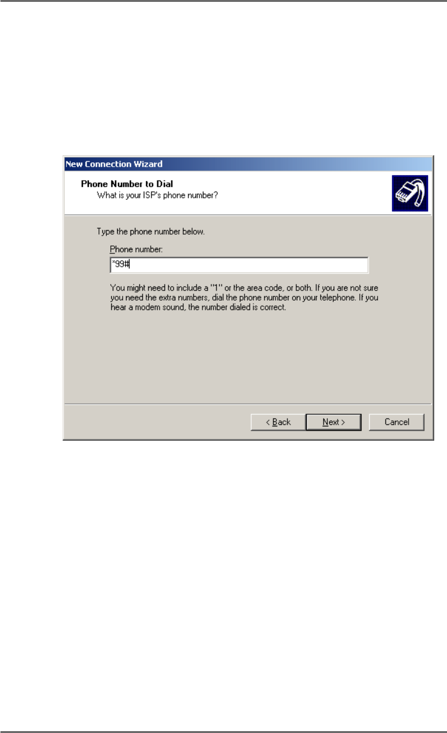
Chapter 4: Using the Interfaces
TT 98-122274-E Using a Data Unit With the EXPLORER™ 500 4-15
4. Select Set up my connection manually.
5. Select Connect using a dial-up modem.
6. Type a name for your connection.
7. When you are asked for a phone number, type:
*98# if you are going to connect to the Internet, and
*99# if you are going to connect to the built-in Web interface of the EXPLORER™ 500.
8. Finish the Wizard.
When you connect to the USB interface, you must open this dial-up connection to access the
Internet or the Web interface.

Chapter 4: Using the Interfaces
TT 98-122274-E Using a Data Unit With the EXPLORER™ 500 4-16
Before Connecting
To connect to the USB interface, use a USB cable mounted with a USB Mini-B connector.
For specifications, refer to USB Interface on page A-6.
Connecting to the USB Interface
If you are connecting your data unit to the USB interface for the first time, see First Time
Setup of USB on page 4-14.
If the units have been connected before, do as follows:
1. Connect the USB cable to the USB port of your data unit.
2. Connect the other end of the cable to the USB connector
on the EXPLORER™ 500.
After power up and pointing, check the connection by opening your dial-up connection as
follows:
1. Select Settings > Network Connections from the Start menu.
2. Locate and open the dial-up connection created for this USB connection.
3. Click OK and wait for the connection to be established. Then start your Internet browser
or mail program.
Note If you intend to use the Launch Pad with the USB interface, you must first install the
C-mux driver from the Inmarsat CD enclosed with the EXPLORER™ 500.
Note The following description is for Windows XP. If you are using a different operating
system, the procedure may be different.
Note If connection fails, refer to Troubleshooting Guide on page 6-4.

Chapter 4: Using the Interfaces
TT 98-122274-E Using a Data Unit With the EXPLORER™ 500 4-17
Handling Bluetooth Device Access
Important!
To be able to handle Bluetooth device access on the EXPLORER™ 500, you need to have a
connected data unit with an Internet browser so you can access the Web interface.
Preparing the EXPLORER™ 500 for Bluetooth
To prepare the Bluetooth interface on the EXPLORER™ 500, do as follows:
1. Access the Web interface and select Settings > Interfaces > Bluetooth.
2. In the UT device name box, type in a name for your EXPLORER™ 500.
This name is shown to other Bluetooth devices, if the EXPLORER™ 500 is configured to
be discoverable.
3. Next to UT discoverable, select yes or no.
• If you select yes, the device name of the EXPLORER™ 500 is shown to other
Bluetooth devices searching for devices.
• If you select no, other Bluetooth devices will not see the EXPLORER™ 500 when
searching for devices.
Pairing Devices
The Bluetooth interface can use various profiles for voice or data. For information on which
profiles are supported, see Bluetooth Interface on page A-7.
If the Bluetooth interface uses a dial-up profile, you have to create a dial-up connection. For
further information, see Creating a Dial-up Connection on page 4-14.
To pair new devices in your EXPLORER™ 500: TBD TBD TBD TBD
Viewing Devices with Access
To see a list of devices that have been paired with the EXPLORER™ 500, do as follows:
Select PROPERTIES > BLUETOOTH DEVICES in the display menu system, or:
1. Access the Web interface.
For further information, see The Web Interface on page 5-1.
2. Select Settings > Interfaces > Bluetooth.
The section Devices with access shows a list of devices that have been paired with the
EXPLORER™ 500.
Note The method for pairing devices may vary depending on your Bluetooth device.
Consult your Bluetooth device documentation for information.

Chapter 4: Using the Interfaces
TT 98-122274-E Using a Data Unit With the EXPLORER™ 500 4-18
Unpairing Devices
To remove a device from the list of Devices with access, you have to use the Web interface.
Do as follows:
1. Locate the Devices with access list as described in Viewing Devices with Access on
page 4-17.
2. In the Devices with access list, click Delete next to the device you want to remove.
When the device is removed from the list, you have to pair it with the EXPLORER™ 500
again to make a connection.
Using a Data Unit with Bluetooth
Connecting a Data Unit to the Bluetooth Interface
If the two devices have not been connected before, you need to pair the devices. For further
information, see Handling Bluetooth Device Access on page 4-17.
When the devices have been paired, do as follows to connect:
1. Power up your data unit and the EXPLORER™ 500.
2. Place the data unit close to the EXPLORER™ 500.
3. Turn on Bluetooth on your device.
If the devices are paired, the Bluetooth connection should now be established.
Note that if your Bluetooth connection is defined as a dial-up connection, you have to
open the dial-up connection before you can access the internet or the Web interface.
Note The procedure may vary depending on the Bluetooth interface in your data unit.
Consult your Bluetooth manual for details.
Note If you intend to use the Inmarsat Launch Pad to access the EXPLORER™ 500
through the Bluetooth interface, you must first install the C-mux driver from the
Inmarsat CD enclosed with the EXPLORER™ 500.
Note If connection fails, check that the interface is on in the EXPLORER™ 500.
If the Bluetooth icon is not present in the display Main screen and in the Home
window of the Web interface, the interface is off.
See Turning an Interface on or off on page 4-3.
If the interface is on, but connection fails, refer to Troubleshooting Guide on
page 6-4.

Chapter 4: Using the Interfaces
TT 98-122274-E Additional Interfaces 4-19
Additional Interfaces
Using an External Antenna
You can connect an external antenna to the EXPLORER™ 500.
The connector for the external antenna is located at the back of the EXPLORER™ 500.
For information on cable and connector type, refer to specifications in External Antenna on
page A-9.
Using the EXPLORER™ 500 Bluetooth Handset Charger
Before Connecting
You can charge your Bluetooth handset using the DC charger interface of the
EXPLORER™ 500.
Use the charger cable supplied with the Bluetooth handset.
For specifications on the charger interface, see EXPLORER™ 500 Bluetooth Handset
Charger Interface on page A-10.
Connecting to the EXPLORER™ 500 Bluetooth Handset Charger Interface
Do as follows:
1. Connect the charger cable to the charging connector on the EXPLORER™ 500.
The charging connector is placed on the rear side of the EXPLORER™ 500.
2. Connect the other end of the cable to your Bluetooth handset.
What’s Next?
This chapter has described the basics of how to set up and use each interface.
The following chapter, Using the Web Interface, describes how to use the built-in Web
interface for setting up and using the EXPLORER™ 500.
Important Only use the specified antenna from Thrane & Thrane. The antenna is listed in
Options and Accessories on page 6-2.

TT 98-122274-E 5-1
Chapter 5
Using the Web Interface 5
In This Chapter
This chapter describes how to use the Web interface to operate, set up and configure the
EXPLORER™ 500.
Initial configuration of interfaces is described in the chapter Using the Interfaces on
page 4-1.
The Web Interface
What is the Web Interface?
The Web interface is a built-in Web server in the EXPLORER™ 500, used for operating,
setting up and configuring the EXPLORER™ 500.
You can access the Web interface from a standard Internet browser, such as Internet Explorer
6.0 or later.
Connecting
Connect your data unit to the EXPLORER™ 500.
Make sure your data unit is set up for the interface you are planning to use for connecting to
the EXPLORER™ 500. You can use LAN, USB or Bluetooth. See Using the Interfaces on
page 4-1 for details.
To access the Web interface, an Internet browser must be installed on the data unit.
Important If you are going to use USB or Bluetooth with Dial-up Networking to access
the Web interface, you must use a dial-up connection with the phone number
set to *99#. For further information, see First Time Setup of USB on
page 4-14.
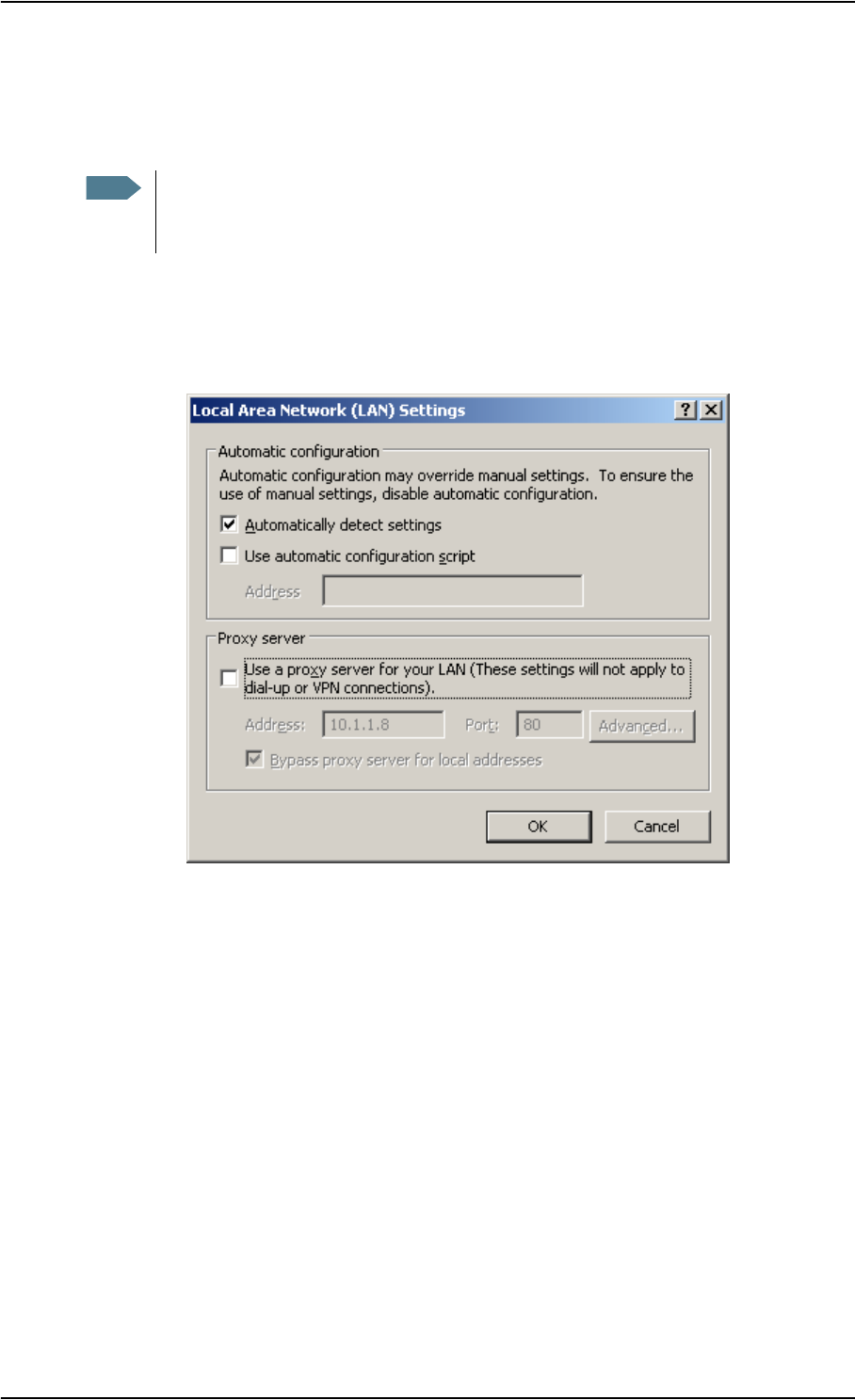
Chapter 5: Using the Web Interface
TT 98-122274-E 5-2
Browser Settings
The Proxy server settings in your browser must be disabled before accessing the Web
interface.
To disable the use of a Proxy server completely, do as follows:
• For Microsoft Internet Explorer, select Tools > Internet Options > Connections > LAN
Settings and uncheck the box labelled Use a proxy server for your LAN. Then click
OK.
• For Safari, select Safari in the top menu bar and select Preferences. Then click Change
Settings next to Proxies.
Click Configure and select the Proxies tab.
In the list, uncheck Web Proxy (HTTP).
When the proxy server settings are disabled, close your browser.
You may need to change this setting back on return to your Internet connection.
Note Most browsers support disabling of the Proxy server settings for a specific IP
address only, so you can disable Proxy server settings for the Web interface only, if
you wish. Consult your browser help for information.
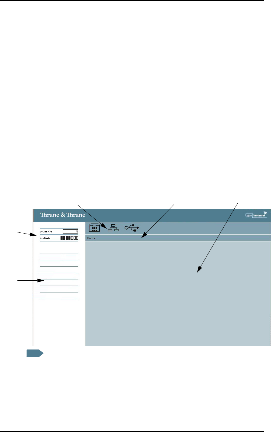
Chapter 5: Using the Web Interface
TT 98-122274-E 5-3
Accessing and Navigating the Web Interface
Accessing the Web Interface
The Web interface is embedded in the EXPLORER™ 500.
To access the Web interface from a connected data unit, do as follows:
1. Start up the EXPLORER™ 500.
For further information, see Getting Started on page 2-1.
2. Open your browser and enter the IP address of the Web interface.
As standard, the IP address is 192.168.0.1.
If your EXPLORER™ 500 uses a different IP address, you can look it up by entering the
display menu system of the EXPLORER™ 500 and selecting PROPERTIES > IP
ADDRESS.
Navigating the Web Interface
The Web interface consists of a navigation pane in the left side holding the main menus and a
status field, an icon bar at the top, and a contents section with status and settings. The bar just
below the icon bar shows the menu path to the currently selected menu item.
Navigation
Status
Icon Bar Contents Section
Pane
Menu Path
Field
Note During pointing, the entire window is replaced by a pointing window. When the
signal strength is acknowledged and pointing is done (or pointing is cancelled), the
Web interface returns to the Home page.
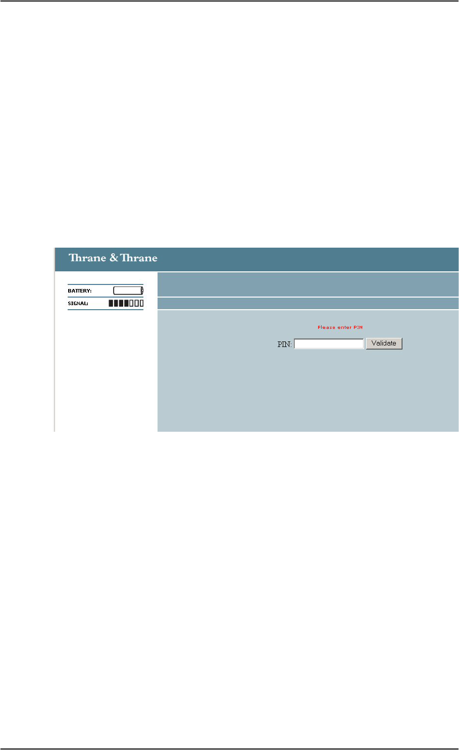
Chapter 5: Using the Web Interface
TT 98-122274-E 5-4
•To expand a menu, click the menu in the navigation pane.
•To access status and settings, click the relevant subject in the navigation pane. The
status or settings are displayed in the main window.
•To see the Site map, click Site map in the navigation pane.
•To return to the Home window from anywhere in the system, click Home, either from
the navigation pane or from the menu path below the icon bar.
Entering the PIN Code in the Web Interface
If a data unit is connected when you start up the EXPLORER™ 500, and the Web interface is
accessed, you can enter the PIN code from the Web interface.
If the PIN code is not entered with the EXPLORER™ 500 keypad, the Web interface will
ask for a PIN code when it is accessed.
Type in the PIN code and press OK.
If you enter a wrong PIN code 3 times you are asked for a PUK code. For further
information, see Wrong PIN Code on page 2-9.
Pointing Using Web Interface
After entering the PIN code, you will see the pointing window in the Web interface, if
pointing is required.
Point the antenna as described in Pointing the Antenna on page 2-10, observing the signal
strength in the Web interface.
When you have obtained the highest possible signal strength, click OK in the Pointing
window.

Chapter 5: Using the Web Interface
TT 98-122274-E 5-5
Viewing the Status
At the top of the navigation pane of the Web interface, you can view the general status of the
EXPLORER™ 500, such as battery level, signal strength and information on ongoing calls
and sessions.
Icons in the top icon bar show which interfaces are turned on, and indicate incoming
messages or alarms.
To view status on total usage (MB or time connected), select Calls from the left navigation
pane in the Web interface. The Calls window shows total usage compared to limits.
Note During pointing, the entire window is replaced by a pointing window. When the
signal strength is acknowledged and pointing is done (or pointing is cancelled), the
Web interface returns to the Home window.
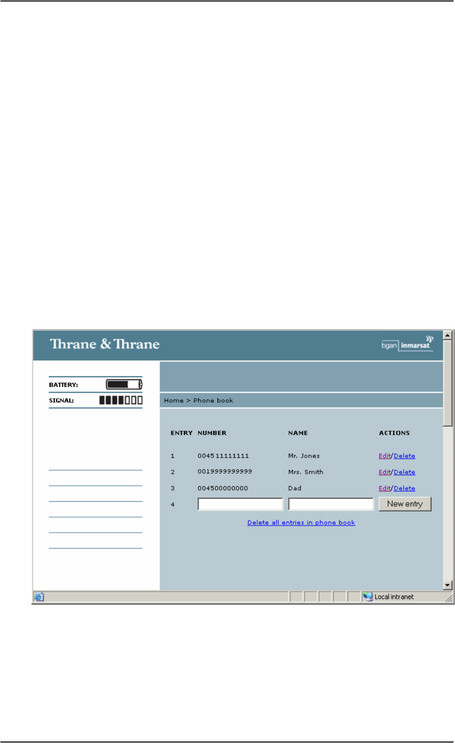
Chapter 5: Using the Web Interface
TT 98-122274-E 5-6
Using the Phone Book
General Usage
With the phone book you can:
• look up phone numbers.
• look up short dial numbers for easy dialling from an analogue or Bluetooth handset.
• send an SMS message.
When sending an SMS message from data equipment using the Web interface, you can
select the number directly from the phone book. For further information, see Sending an
SMS Message From the EXPLORER™ 500 on page 5-8
• modify or delete existing names and phone numbers, or enter new names and phone
numbers.
Accessing the Phone Book
To access the phone book, select Phone book from the left navigation pane.
The phone book shows all the entries with an entry number, phone number and name.

Chapter 5: Using the Web Interface
TT 98-122274-E 5-7
Short Dial
The entry number in the phone book is the Short dial number. When making a call from the
EXPLORER™ 500 you can use this number instead of dialling the entire phone number.
Simply dial: <short dial> followed by * and # or off-hook key.
Example: To call the 3rd entry in the phone book from an analogue phone, take the phone
off hook and dial 3 * #.
Adding a New Entry
To add a new entry, do as follows:
1. In the phone book, locate the empty entry number where you want to add the new phone
number.
2. Click New entry.
3. Type in the name and number of the new entry and click OK.
The new name and number is now listed at the specified entry number in the phone book.
Modifying an Entry in the Phone Book
To modify an entry, do as follows:
1. In the phone book, click Edit next to the entry you want to modify.
2. Modify the name or number as wanted and click Save Entry.
The name and/or number in the selected entry is now replaced with the new information.
Deleting an Entry in the Phone Book
To delete an entry, do as follows:
1. In the phone book, click Delete next to the entry you want to delete.
2. Click OK to confirm.
The selected entry is now empty.
Deleting all Entries in the Phone Book
To delete all the entries in the phone book, do as follows:
1. Click Delete all entries in phone book at the bottom of the Phone book window.
2. Click OK to confirm.

Chapter 5: Using the Web Interface
TT 98-122274-E 5-8
Handling Messages
Sending an SMS Message From the EXPLORER™ 500
To send an SMS message from the EXPLORER™ 500, do as follows:
1. Click Messages from the left navigation pane.
The Inbox opens.
2. In the left navigation pane, click Write message.
3. Type in the message in the Message field.
4. Type in the phone number in the Recipient field, or click a number from the Phone book
below the Recipient field.
When typing the number, remember 00 and country code
(e.g. 00 45 to call Denmark or 00 1 to call USA).
5. Select whether or not you want delivery notification for this SMS message.
If you click Yes, you will get a notification when your message has arrived.
6. Click Send.
The message is now moved to the Outbox. If the EXPLORER™ 500 is online, the
message is sent.
Sending an SMS Message to the EXPLORER™ 500
Send the SMS message e.g. from a mobile phone, using one of the mobile numbers for voice.
Dial:
+870 <Mobile number>
To see the voice numbers, select Properties from the Web interface or from the display
menu system and view Mobile numbers.
Note You can set up delivery notification generally for all SMS messages. For further
information, see Setting up the Message Options on page 5-10.

Chapter 5: Using the Web Interface
TT 98-122274-E 5-9
Receiving a Message
If a message has arrived, the status bar at the top of the Web interface shows an unopened
envelope. Click the envelope to see the new message(s).
Otherwise, to see received messages, click Messages from the left navigation pane.
The window shows all received messages.
If the message is not an SMS message but information of Voice mail, you have to call your
Voice mail service number to hear the Voice mail.
To find your Voice mail service number, select Messages > Settings and locate the Voice
mail service number.
Options for SMS Messages in the Inbox
To enter the Inbox, click Messages from the left navigation pane.
Besides viewing the messages in the Inbox, you have a number of options for what to do with
each message:
• Click Reply to reply to a message.
Type in your reply and click Send.
For information on how to include the original message in your reply, see Setting up the
Message Options on page 5-10.
• Click Forward to forward a message to someone.
Then type in the phone number in the Recipient field or pick from the phone book, and
click Send.
• Click Delete to delete the message. Then click OK to confirm.
• Click Delete all entries in inbox to delete the entire contents of the inbox. Then click OK
to confirm.
Note The EXPLORER™ 500 does not accept incoming messages if the Inbox is full. The
Inbox can hold up to 100 messages. When the Inbox is full, you have to delete
messages or move them to the SIM card, in order to free space for new messages.

Chapter 5: Using the Web Interface
TT 98-122274-E 5-10
Configuring Message Settings
Setting up the Message Options
You can set up general options for your outgoing messages. These settings normally apply to
all your outgoing messages. Note, however, that you can also change these settings for an
individual message. For further information, see Sending an SMS Message From the
EXPLORER™ 500 on page 5-8.
Do as follows:
1. Select Messages > Settings from the left navigation pane.
2. Select the following message options:
•Include message in reply.
To include the original message when you reply, click Ye s .
•Delivery notification.
To receive notification when your message is delivered, click Ye s .
Viewing or Changing SMS Service Number
The SMS service number identifies the SMS service centre used when sending and receiving
SMS messages. Normally you do not need to know this number, but the EXPLORER™ 500
uses it when sending or receiving SMS messages.
The SMS service number is stored on the SIM card.
• To see the SMS service number, select
Messages > Settings from the left navigation pane.
• To change the number, click Edit next to SMS service number, change the number and
click OK.
The SMS service number is provided from your Airtime provider.
Viewing or Changing Voice Mail Service number
The Voice mail service number is the number you call to hear your incoming voice mails.
The Voice mail service number is stored on the SIM card.
• To see the Voice mail service number, select
Messages > Settings from the left navigation pane.
• To change the number, click Edit next to Voice mail service number, change the
number and click OK.

Chapter 5: Using the Web Interface
TT 98-122274-E 5-11
Power up Behaviour
Automatic Power up
In the Power up section of the Settings window, select whether or not the
EXPLORER™ 500 should power up automatically when external power is applied.
• To have the EXPLORER™ 500 power up automatically when external power is applied,
select Ye s.
• To have the EXPLORER™ 500 power up only when the power button is pressed, click
No.
Pointing at Power up
If the EXPLORER™ 500 is placed in a fixed position it may not be necessary to go through
the pointing process every time the terminal is powered. You can set up the
EXPLORER™ 500 to automatically establish a connection to the BGAN network, if you
know that the signal strength is sufficient.
In the Power up section of the Settings window, select whether or not pointing is required at
power up.
• To go through the pointing process next time the EXPLORER™ 500 is powered, select
Ye s .
• To have the EXPLORER™ 500 automatically acknowledge the signal strength next time
the EXPLORER™ 500 is powered, select No.
If you have selected that pointing is not required at power up, the start up procedure will be
as follows:
1. Power up.
2. Enter PIN code.
After the PIN code is entered, the EXPLORER™ 500 immediately tries to connect to the
BGAN network.
The terminal display shows the progress as follows:
•SEARCHING (this phase can be very short and may not be seen)
• ATTACHING
• READY
Setting the Display Contrast and Brightness
To set the display contrast and brightness, do as follows:
1. Select Settings > Terminal Display from the left navigation pane.
2. In the Brightness section of the Terminal display window, set the timing.
The Timed period is the period of time the light will stay on after the last key is pressed.

Chapter 5: Using the Web Interface
TT 98-122274-E 5-12
3. Set the brightness level with the scroll bar.
4. In the Contrast section, click Automatic on if you want the contrast to be adjusted
automatically according to the temperature.
5. Set the contrast level with the scroll bar.
Turning Audio Indicators on or off
In the Audio indicators section of the Terminal display window, turn the audio indicators
on or off using the radio buttons.
The EXPLORER™ 500 has audio indicators for the following events:
•Pointing
The Pointing indicator is a beeping sound during the pointing process. The beeping
frequency increases with the signal strength.
• Messages
The Message indicator is a sound indicating that a message has arrived.
• Warnings
The Warning indicator is a sound indicating that a warning is issued.
A warning can be issued if, for example, the battery charge level is too low.
•Alarms
The Alarm indicator is a sound indicating that an alarm is issued.
An alarm can be issued if, for instance, the temperature is too high.
Enabling Activation of Stealth Mode
In Stealth mode, the EXPLORER™ 500 operates with no sounds nor lights. However, it is
still possible to operate the terminal and the display text is readable.
To enable the use of Stealth mode for the EXPLORER™ 500, do as follows:
1. Select Settings > Terminal display from the left navigation pane.
2. In the Stealth Mode section, click Enable.
Important Only enable activation of Stealth mode if you are going to use it. If Stealth
mode is activated by mistake, it may be difficult to operate the
EXPLORER™ 500.
Note This setting does not activate Stealth mode, it only enables the use of Stealth
mode. To activate Stealth mode, press C+OK.
To deactivate Stealth mode and return to normal function, press C+OK again.

Chapter 5: Using the Web Interface
TT 98-122274-E 5-13
Overview of Network Settings
There are several network parameters that can be set up in the Web interface. This section
gives an overview of these parameters, but does not provide detailed information.
APN (Access Point Name)
The APN is used by the mobile user to establish the connection to the required destination
network. This means that the EXPLORER™ 500 must know the APN in order to be able to
connect to the destination network.
APNs are provided from the Airtime Provider. They may also be defined on the SIM card.
DNS (Domain Name Server)
The DNS translates domain names into IP addresses. A DNS needs to be assigned, to enable
your browser to recognize domain names and translate them into the correct IP addresses.
Two DNSes are defined; the second DNS is used as backup.
The DNSes are provided from the Airtime Provider.
Header Compression
The Header of a data packet contains control information belonging to that packet. The
information in the Header can take up a considerable amount of bandwidth. In order to save
bandwidth, you can use Header Compression, meaning you compress the header
information, leaving some of the information out.
You can select whether or not to use Header Compression for your data transmission.
•Header Compression on: Recommended for low-noise applications.
If you select Header Compression on, you will be using less bandwidth on header
information, leaving more bandwidth for the actual payload.
However, if the environment is noisy, the system will have to retransmit information, and
you may end up using more bandwidth than without Header Compression.
•Header Compression off: Recommended in noisy environments.
If Header Compression is off, the system will be less sensitive to noise.
TCP/IP Spoofing
Some packet data applications will not work efficiently with the extra delay introduced by a
satellite link. In many cases, but not all, this problem can be solved using a technique called
TCP speed-up or TCP acknowledge spoofing.
Primary and Secondary Connection Class
The Connection Class defines the Quality of Service used for your data transmission. You
can select between a number of predefined profiles.
A profile is basically a collection of settings to define the priority of data transmitted on an
interface.

Chapter 5: Using the Web Interface
TT 98-122274-E 5-14
NAT (Network Address Translation)
NAT enables a local-area network to use one set of private IP addresses for internal traffic
and an assigned or static IP address for external traffic. The built-in NAT module in the
EXPLORER™ 500 makes all necessary address translations between the local-area traffic
and the external traffic.
If more than one user is connected to the LAN interface of the EXPLORER™ 500, it is
necessary to use a switch, as the EXPLORER™ 500 only has one LAN connector. If you are
using a switch, you must select NAT on to use the NAT of the EXPLORER™ 500.
Configuring the LAN Interface
For an explanation of each of the network settings, see Overview of Network Settings on
page 5-13.
To configure the LAN interface, do as follows:
1. Select Settings > Interfaces > LAN.
2. At the top of the page, select whether the LAN interface should be on or off.
3. If your data unit uses a static IP address, click yes next to Use static IP address.
To check whether you data unit uses a static IP address, see the properties of the LAN
connection on your data unit. (In Windows XP, select Settings > Network Connections >
Local Area Connection).
4. To use TCP/IP spoofing, click On.
5. Select APN.
There are two possibilities for setting the APN:
•From SIM. If APNs are available on the SIM card, you must select one of these APNs
from the scroll list.
•User defined. Type in the APN. APNs are provided from the Airtime provider.
6. Type in the User name and password for the APN. The user name and password are
provided from the Airtime provider.
7. Select DNS.
You have two possibilities for setting the DNS:
•Network assigned. The DNS1 and DNS2 are assigned from the network if possible.
•User defined. Type in the DNS1 and DNS2 provided from the Airtime provider.
8. Select the Primary Connection Class.
Select a profile from the scroll list.
CAUTION! If you are connected using LAN while changing the below
settings, your changes may affect your current connection.

Chapter 5: Using the Web Interface
TT 98-122274-E 5-15
9. Select the Secondary Connection Class.
To select more than one secondary profiles, press and hold Ctrl while selecting.
10.To use the built-in NAT of the EXPLORER™ 500, select NAT: On.
Configuring the USB Interface
For an explanation of each of the network settings, see Overview of Network Settings on
page 5-13.
To configure the USB interface, do as follows:
1. Select Settings > Interfaces > USB.
2. If your data unit uses a static IP address, click yes next to Use static IP address.
3. To use TCP/IP spoofing, click On.
4. Select APN.
You have two possibilities for setting the APN:
•From SIM. The APN is taken from the SIM card.
•User defined. Type in an APN provided from your Airtime provider.
5. Type in the APN user name and password provided from your Airtime Provider.
6. Select DNS.
You have two possibilities for setting the DNS:
•Network assigned. The DNS1 and DNS2 are assigned from the network, if possible.
•User defined. Type in DNS1 and DNS2 provided from your Airtime provider.
7. Select the Primary Connection Class.
Select a profile from the scroll list.
8. Select the Secondary Connection Class.
To select more than one secondary connection class, press and hold Ctrl while selecting.

Chapter 5: Using the Web Interface
TT 98-122274-E 5-16
Configuring the Bluetooth Data Interface
For an explanation of each of the network settings, see Overview of Network Settings on
page 5-13.
Up to 7 devices, including phones and data units, can be connected to the Bluetooth interface.
To configure a Bluetooth data connection, do as follows:
1. In the Bluetooth window, locate your data unit in the DATA UNITS list below the
Devices with access list.
2. If your data unit uses a static IP address, click yes next to Use static IP address.
3. To use TCP/IP spoofing, click On.
4. Select APN.
You have two possibilities for setting the APN:
•From SIM The APN is taken from the SIM card (if available)
•User defined. Type in an APN provided from your Airtime provider.
5. Type in the User name and password for the APN. The user name and password are
provided from the Airtime provider.
6. Select DNS.
You have two possibilities for setting the DNS:
•Network assigned. The DNS1 and DNS2 are assigned from the network.
•User defined. Type in the DNS1 and DNS2 provided from your Airtime provider.
7. Select the Primary Connection Class.
Select a profile from the scroll list.
8. Select the Secondary Connection Class.
To select more than one secondary connection class, press and hold Ctrl while selecting.
9. To use the built-in NAT of the EXPLORER™ 500, select NAT: On.
CAUTION! If you are connected using Bluetooth while changing the below
settings, your changes may affect your current connection.

Chapter 5: Using the Web Interface
TT 98-122274-E 5-17
Changing or Disabling the PIN Code
To access the PIN code options, select Settings > Security from the left navigation pane.
Changing the PIN Code
1. In the Change PIN Code section of the Security window, type in the current PIN code in
the Current PIN code field.
2. Type in the new PIN code in the first New PIN code field.
The PIN code must be from 4 to 8 digits long.
3. Repeat the new PIN code in the next New PIN code field.
4. Click Apply.
Disabling the PIN Code
1. In the Disable PIN Code section of the Security window, type in the current PIN code in
the Current PIN code field.
2. Click Disable.
The PIN code is disabled. Access to the EXPLORER™ 500 will no longer require a PIN
code.
Note If you need to reenable the use of PIN code, select
Settings > Security again, enter the PIN code and click Enable.

Chapter 5: Using the Web Interface
TT 98-122274-E 5-18
Viewing Properties of the EXPLORER™ 500
Properties
To view the properties of the EXPLORER™ 500, select Properties from the left navigation
pane.
The Properties window shows:
•Current IP address. The IP address of the built-in Web interface in the
EXPLORER™ 500.
•IMEI number. The IMEI number (International Mobile Equipment Identity) of the
EXPLORER™ 500. This is a unique number that identifies your EXPLORER™ 500.
IMEI numbers are stored in a database containing all valid mobile phone equipment.
•SMS service number. A number used to identify the SMS service centre used by your
EXPLORER™ 500 to send and receive SMS messages.
•Voice mail service number. The phone number to call to hear your Voice mail.
•Mobile numbers. The numbers to use for Standard voice, Premium voice and IP
connection when calling the EXPLORER™ 500.
•Hardware information.The unit serial number and PCB numbers of the
EXPLORER™ 500.
•Software information. The software version.
Viewing the Alarm List
To view the Alarm list, select Properties > Alarm list from the left navigation pane.
The Alarm list window shows a detailed list of active alarms.

Chapter 5: Using the Web Interface
TT 98-122274-E 5-19
Updating Software
Updating Software Using the Web Interface
To update the software of the EXPLORER™ 500, do as follows:
1. Acquire the new software version from Thrane & Thrane and save it on your PC.
2. In the Web interface, select Properties from the left navigation pane.
3. Locate the Software information field and check the current version of the
EXPLORER™ 500 software.
4. To upload new software, click Upload.
5. Click Browse.
6. Browse to the new software version and select it.
7. Click OK.
The software is now updated. Note that you have to restart the EXPLORER™ 500 to
activate the new software.
Updating the Software Using the Keypad
To update the software of the EXPLORER™ 500, do as follows:
1. Acquire the new software version from Thrane & Thrane and save it on your PC.
2. Connect a USB cable between your PC and the EXPLORER™ 500.
Refer to Using the USB Interface on page 4-14.
3. TBD
4. Press and hold the C button while you power up the EXPLORER™ 500.
TBD
Accessing the Help Desk
If you need help regarding airtime, you may call the Help desk. The Help desk is the phone
number for your airtime provider.
Select Help desk from the left navigation pane.
The helpdesk number can be taken from the SIM card or entered manually. To change the
number, click Edit, change the number and click OK.

Chapter 5: Using the Web Interface
TT 98-122274-E 5-20
Generating a Diagnostic Report
If you want to generate a diagnostic report, select Help desk form the left navigation pane
and click Generate report. The report is saved to a file, which you can enclose when
reporting an error.
The diagnostic report contains relevant information for troubleshooting, such as the error log,
the alarm log, the list of currently active alarms and the call log (phone numbers not
included).
What’s Next?
This chapter has explained how to use the Web interface for setup and use of the
EXPLORER™ 500. You should now be able to set up the EXPLORER™ 500, pair
Bluetooth devices, check status, read and send SMS messages, use the phone book and much
more.
The following chapter, Maintenance and Troubleshooting, provides guidelines for
troubleshooting and for general maintenance.

TT 98-122274-E 6-1
Chapter 6
Maintenance and Troubleshooting 6
In This Chapter
This chapter gives guidelines for troubleshooting and for general maintenance. It also
provides an overview of the different means of status signalling,
Getting Support
If this manual does not provide the information required to solve your problem, you may
want to contact your Airtime Provider or your local distributor.
Airtime: If you need assistance from your Airtime provider, please call the help desk.
To see the help desk number, enter the display menu system of your EXPLORER™ 500 and
select HELP DESK.
EXPLORER™ 500: If you need assistance regarding problems caused by the
EXPLORER™ 500 terminal, please call a distributor in your area. Click the following link to
see a list of Thrane & Thrane distributors.
List of Distributors
Recharging the Battery
It is recommended to fully charge the battery before using the EXPLORER™ 500 for the
first time.
To charge the battery, insert it into the EXPLORER™ 500 and connect the
EXPLORER™ 500 to power.
The indicator left to the display is constantly green as long as the battery is charging. When
the battery is fully charged, the green indicator is turned off. If the EXPLORER™ 500 is
switched on, the green indicator will be flashing shortly every 2 seconds.
If a charging error occurs, the green indicator on the EXPLORER™ 500 flashes rapidly. If
this is the case, check that
• the battery is properly inserted
• the power cable and adapter are properly connected
If the battery is not functional, please acquire a new battery. For information on how to
replace the battery, see Removing the Battery on page 2-3 and Inserting the Battery on
page 2-2.
Note This list of distributors is static, so it may not always be up to date.
An updated list is available on Thrane & Thrane’s web site: www.thrane.com. Click
Land Mobile and select Distributors from the top menu bar.
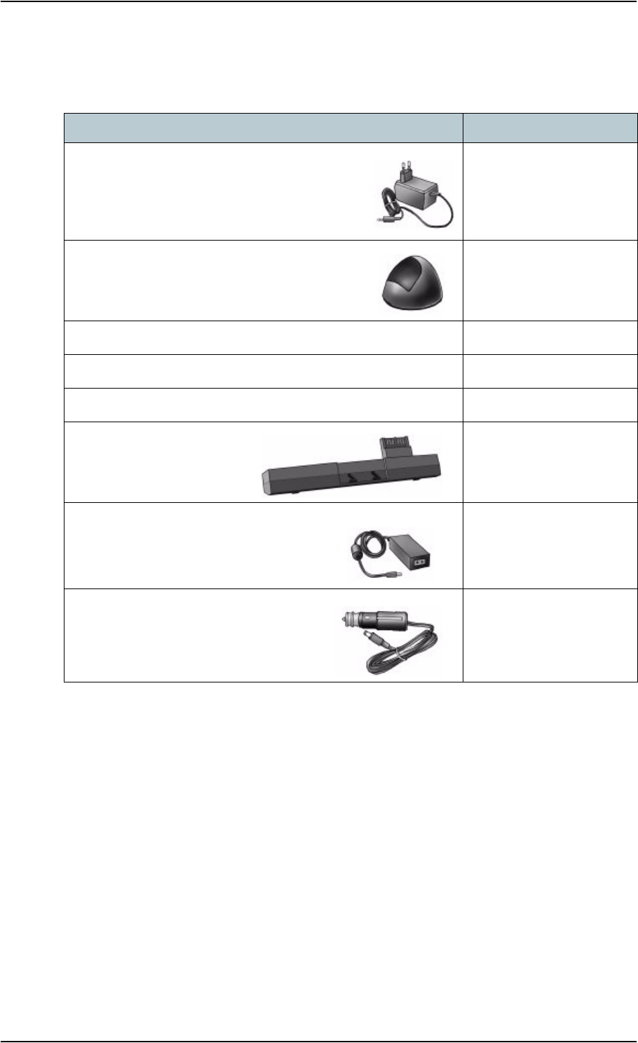
Chapter 6: Maintenance and Troubleshooting
TT 98-122274-E 6-2
Options and Accessories
The following options and accessories are available from Thrane & Thrane:
Item Number
EXPLORER™ 500 Bluetooth
Handset + charger
TT-3625A
Desktop charger cradle for Bluetooth handset
Opt. 003
External antenna + 10 m antenna cable and pole mount kit TT-3008I
Pole mount kit Opt. 922
Softbag for the EXPLORER™ 500 Opt. 202
Battery for the
EXPLORER™ 500
TT-3686L
AC/DC power supply
TT-3682L
Car charger cable (37-108299-A)
Opt. 009

Chapter 6: Maintenance and Troubleshooting
TT 98-122274-E 6-3
Upgrading Software
Viewing Software Version Status
To view the version of the embedded software in the EXPLORER™ 500, select Properties
in the Web interface or in the display menus and see Software information.
Updating Software Using the Web Interface
To update the software of the EXPLORER™ 500, do as follows:
1. Acquire the new software version from Thrane & Thrane and save it on your PC.
2. In the Web interface, select Properties from the left navigation pane.
3. Locate the Software information field and check the current version of the
EXPLORER™ 500 software.
4. To upload new software, click Upload.
5. Click Browse.
6. Browse to the new software version and select it.
7. Click OK.
The software is now updated. Note that you have to restart the EXPLORER™ 500 to
activate the new software.

Chapter 6: Maintenance and Troubleshooting
TT 98-122274-E 6-4
Troubleshooting Guide
The below table provides information on some of the problems that might occur, including
possible causes and solutions to the problems.
Problem Possible Cause Solution
The
EXPLORER™ 500
cannot be turned on, or
does not stay on when
powered by the battery.
The battery needs
recharging.
Charge the battery. Check the battery
indicator in the display.
The battery is not
inserted properly.
Remove the battery and re-insert it.
Make sure the battery is inserted
properly and that the latch is locked.
The battery contacts
are dirty or damaged.
Clean the battery contacts if necessary.
If the contacts are damaged, replace
the battery.
Charging error -
The green Power
indicator flashes
rapidly while the
battery is being
charged.
The temperature is
below 0°C or above
45°C.
Only charge the battery when the
temperature is within the range 0°C to
45°C.
The charging voltage
is less than 9 V.
Check that the voltage applied to the
DC input of the EXPLORER™ 500 is
within the specified range
(+10 to +16 V DC).
If the DC input is within limits, and the
error persists, contact your local
distributor.
The display shows
INSERT SIM.
The SIM card is not
present.
Remove the battery and insert the SIM
card in the SIM card slot according to
the instructions in the section
Inserting the SIM Card on page 2-2.
The SIM card is not
inserted properly.
Remove the SIM card and re-insert it
according to the instructions in the
section Inserting the SIM Card on
page 2-2.

Chapter 6: Maintenance and Troubleshooting
TT 98-122274-E 6-5
The
EXPLORER™ 500
cannot obtain its
position using GPS
There is no GPS
signal, or the signal is
weak.
Check the GPS status in the display or
the Web interface.
Make sure the GPS antenna has a clear
view of the sky.
Place the EXPLORER™ 500 flat on a
surface to obtain the best possible
view.
It can take up to 10
minutes to obtain the
GPS position.
Wait 10 minutes.
If you know the approximate direction
to the BGAN satellite, you can start
the pointing process before the GPS
position is found.
No signal or weak
signal from the satellite
The view to the
satellite is blocked
Make sure the EXPLORER™ 500 has
a clear view to the satellite. Be aware
that window glass may reduce the
signal level.
The antenna is
pointed in the wrong
direction
Check that the antenna is pointed
according to the position data.
Adjust the position to the highest
possible signal strength.
Problem Possible Cause Solution

Chapter 6: Maintenance and Troubleshooting
TT 98-122274-E 6-6
Connection to the
Internet cannot be
established
The signal strength is
too low.
Check that the antenna is pointed
according to the position data.
Adjust the position to the highest
possible signal strength.
For information on minimum required
signal strength for a particular service,
see Minimum Signal Strength on
page 2-11.
Your connection is
defined as a dial-up
connection, but you
have not opened the
dial-up connection.
You need to open the dial-up
connection before you can connect to
the Internet.
Your connection is a
dial-up connection,
but you have not
entered the phone
number *98# to
indicate a connection
to the Internet.
Change the phone number in the dial-
up connection to *98# and open the
dial-up connection before accessing
the Internet.
The Web interface
cannot be accessed
The browser is
configured to use a
proxy server
For Microsoft Internet Explorer, select
Tools > Internet Options >
Connections > LAN Settings and
uncheck Use a proxy server for your
LAN.
You have entered a
wrong IP address
Check the IP address and re-enter it.
Your connection is
defined as a dial-up
connection, but you
have not opened the
dial-up connection.
You need to open the dial-up
connection before you can connect to
the Web server.
Your connection is a
dial-up connection,
but you have not
entered *99# as the
phone number to
indicate that this is a
connection to the
Web interface.
Change the phone number in the dial-
up connection to *99# and open the
dial-up connection before accessing
the Web interface.
Problem Possible Cause Solution

Chapter 6: Maintenance and Troubleshooting
TT 98-122274-E 6-7
A Phone/Fax
connection cannot be
established
The interface is off in
the
EXPLORER™ 500
Turn on the interface by entering the
display menu system and selecting
SETTINGS > INTERFACES >
PHONE/FAX > ON
The cable is not
properly connected
Connect the cable.
The cable type or
connector type is not
correct
For information on the correct type of
connector and cable, refer to
Phone/Fax Interface on page A-4.
Incoming calls: The
voice quality used for
the call is not selected
in the Web interface.
Make sure the voice quality used for
calls to the terminal is selected in the
Web interface. Access the Web
interface and select SETTINGS >
INTERFACES > PHONE/FAX. Then
select the voice quality for incoming
calls.
A Bluetooth handset
connection cannot be
established
The interface is off in
the
EXPLORER™ 500
Turn on the interface by entering the
display menu system and selecting
SETTINGS > INTERFACES >
BLUETOOTH > ON
The Bluetooth
handset is placed too
far away from the
EXPLORER™ 500
Bring the handset closer to the
EXPLORER™ 500.
Note that the specified maximum
distance is only valid under ideal
conditions.
The handset is not yet
paired with the
EXPLORER™ 500
Pair the devices. Refer to Making a
Call To the EXPLORER™ 500 on
page 4-9.
Incoming calls: The
voice quality used for
the call is not selected
in the Web interface.
Make sure the voice quality used for
calls to the terminal is selected in the
Web interface. Access the Web
interface and select SETTINGS >
INTERFACES > BLUETOOTH. Then
select the voice quality for incoming
calls.
Problem Possible Cause Solution

Chapter 6: Maintenance and Troubleshooting
TT 98-122274-E 6-8
A LAN connection
cannot be established
The interface is off in
the
EXPLORER™ 500
Turn on the interface by entering the
display menu system and selecting
SETTINGS > INTERFACES > LAN >
ON
The cable is not
properly connected
Connect the cable.
The cable type or
connector type is not
correct
For information on the correct type of
connector and cable, refer to LAN
Interface on page A-5.
The interface is not
configured correctly.
For configuration of the interface, see
Configuring the LAN Interface on
page 5-14.
A USB connection
cannot be established
The interface is off in
the
EXPLORER™ 500
Turn on the interface by entering the
display menu system and selecting
SETTINGS > INTERFACES > USB >
ON
The cable is not
properly connected
Connect the cable.
The cable type or
connector type is not
correct
For information on the correct type of
connector and cable, refer to USB
Interface on page A-6.
The dial-up
connection is not
created correctly.
Refer to First Time Setup of USB on
page 4-14.
The interface is not
configured correctly.
For configuration of the interface, see
Configuring the USB Interface on
page 5-15.
Problem Possible Cause Solution

Chapter 6: Maintenance and Troubleshooting
TT 98-122274-E 6-9
A Bluetooth data
connection cannot be
established
The interface is off in
the
EXPLORER™ 500
Turn on the interface by entering the
display menu system and selecting
SETTINGS > INTERFACES >
BLUETOOTH > ON
The data unit is
placed too far away
from the
EXPLORER™ 500
Bring the data unit closer to the
EXPLORER™ 500.
Note that the specified maximum
distance is only valid under ideal
conditions.
The data unit is not
yet paired with the
EXPLORER™ 500
Pair the devices. Refer to Making a
Call To the EXPLORER™ 500 on
page 4-9.
The interface is not
configured correctly.
For configuration of the interface, see
Configuring the Bluetooth Data
Interface on page 5-16.
Problem Possible Cause Solution

Chapter 6: Maintenance and Troubleshooting
TT 98-122274-E 6-10
Status Signalling
There are many ways of troubleshooting if an error occurs. The EXPLORER™ 500 has
different means of status signalling, to help you find the cause of a problem:
•Indicators.
The function of the light indicators next to the
display is described in Light Indicators on
page 1-7.
•Error messages.
• Log files.
Error messages and log files are described in the following sections.
Error Messages
Types of Error messages
Different types of error messages can appear in the EXPLORER™ 500.
• Messages received from the network describe the network related conditions, such as
“network busy”.
• Messages generated by the EXPLORER™ 500 describe errors related to the terminal
itself. For example, this could be information that the temperature is too high.
TBD
Display of error messages
When an alarm is issued, the display shows that there is an active alarm and the red indicator
next to the display is flashing. If you press OK, the display returns to the Main screen, with
the text VIEW ALARM LIST? If you press OK again, the list of currently active alarms
appears.
As long as the cause of an alarm is still present, the red indicator keeps flashing.
Messages are logged in the Alarm log, which can be viewed with the Web interface. For
information on the Alarm log, see Alarm Log on page 6-11.
TBD

Chapter 6: Maintenance and Troubleshooting
TT 98-122274-E 6-11
Log Files
Note
When contacting Thrane & Thrane for support, please include a diagnostic report.
The diagnostic report contains the log files and other information relevant when
troubleshooting.
To generate the diagnostic report, access the Web interface and select Help Desk. Then click
Generate report.
Alarm Log
The alarm log holds information of errors found by the EXPLORER™ 500 during
continuous monitoring.
The log includes the time of the error, a short description, location of the error etc. This
information can help you troubleshoot errors in the EXPLORER™ 500.
Call Log
The call log holds information of up to 100 calls and data sessions to/from the
EXPLORER™ 500.
The call log contains detailed information, such as date, time, phone numbers, duration, Mb
transferred etc., for each call or data session.
Date and time is UTC time, received from the satellite.

TT 98-122274-E A-1
Appendix A
Technical Specifications A
In This Appendix
This appendix contains technical specifications for the EXPLORER™ 500.
General Specifications
The EXPLORER™ 500 meets or exceeds current and proposed Inmarsat specifications for
operation on the Inmarsat Broadband Global Area Network.
Item Specification
Type BGAN Class 2 User Terminal
Max. data ratea
Downlink
Uplink
a. Performance depends on a wide range of factors and actual usage.
464 kbps (shared)
448 kbps (shared)
Physical dimensions 218 mm x 216 mm x 52 mm/
8.6” x 8.5” x 2.0”
Weight (incl. Battery) 1.3 kg/2.9 lbs
Environmental conditions
Operating temperature
Powered by external DC
Powered from battery
Storage temperature
Without battery
With battery
Relative humidity
Water & Dust
Max. wind-load
-25°C to +55°C/-13°F to +131°F
0°C to +55°C/+32°F to +131°F
-40°C to +80°C/-40°F to +176°F
-20°C to +60°C/-4°F to +140°F
95% non-condensing at +40°C/+104°F
IP-54 (dust and spray proof in all directions)
18 m/s or 59 ft/s (Operational)
Robustness 0.5 m/1.64 ft drop on concrete (Operational, 95%
survival)

Appendix A: Technical Specifications
TT 98-122274-E A-2
Battery
Specifications
Item Specification
Battery type Lithium ion (Rechargeable)
Voltage 11.1 V
Capacity 2.2 Ah
Time between recharging
Standby time
Data transmission
36 h
1 h 30 m @144 kbps
Charge timea
a. Performance depends on a wide range of factors and actual usage.
Less than 3 hours
(when the terminal is switched OFF)
Charge temperature 0°C to +45°C/+32°F to +113°F Ambient
Min. charge cycles 300
Storage temperature
1Month
3Months
1Year
-20°C to +60°C/-4°F to +140°F Ambient
-20°C to +45°C/-4°F to +113°F Ambient
-20°C to +20°C/-4°F to +68°F Ambient

Appendix A: Technical Specifications
TT 98-122274-E A-3
Power Input
Connector Pin-Out
This drawing shows the pin-out for the DC
power connector.
Specifications
AC/DC Power supply
SIM Interface
+
GND
Item Specification
DC input range +10 to +16 V DC
Power consumptiona
Standby mode
Transmit mode
During charging
a. Performance depends on a wide range of factors and actual usage.
0.5 to 1 W (Typical)
14 W (Typical)
38 W max.
Connector type 2.5 mm EIAJ RC-5320-IV
Item Specification
AC input range 100 to 240 V AC, 47 to 63 Hz
DC output 15 V DC, 50 W
Item Specification
Slot type Standard USIM card holder

Appendix A: Technical Specifications
TT 98-122274-E A-4
Phone/Fax Interface
Connector Pin-Out
The pin-out for the Phone/fax connector is as follows:
Specifications
Pin Function
1NC
2Tip
3Ring
4NC
1234
RJ-11 Connector
Female (Receptacle)
Item Specification
Connector type RJ-11
Impedance 600Ω
Max. cable length 400 m/1312 ft
Max. units connected One unit

Appendix A: Technical Specifications
TT 98-122274-E A-5
LAN Interface
Connector Pin-Out
The pin-out for the LAN connector is as follows:
Specifications
Pin Function
1Rx +
2Rx -
3Tx +
4NC
5NC
6Tx -
7NC
8NC
RJ-45 Connector
Female (Receptacle)
Item Specification
Connector type RJ-45, MDI-X (IEEE 802.3 10/100BaseT)
Standard ISO/IEC 8877:1992 and
IEEE 802.3 1998 Edition
Max. data rate 100 Mbps
Max. cable length 100 m/328 ft with Cat5 UTP
Supported web browser Microsoft Internet Explorer 6.0 or later
Default IP Address 192.58.0.1
Operating Systems Microsoft Windows 2000,
Microsoft Windows XP,
Mac OS 9.2,
Mac OS 10.1,
Linux Redhat 9

Appendix A: Technical Specifications
TT 98-122274-E A-6
USB Interface
Connector Pin-Out
The pin-out for the USB connector is as follows:
Specifications
Pin Function
1NC
2D -
3D +
4NC
5 GND
Mini-USB Type A/B
Female (Receptacle)
Item Specification
Version 1.1 (Slave)
Connector type Mini-B
Max. data rate 12 Mbps
Max. cable length 5 m/16.4 ft
Max. units connected 7 physical devices
Operating Systems Microsoft Windows 98SE,
Microsoft Windows ME,
Microsoft Windows NT 4.0,
Microsoft Windows 2000,
Microsoft Windows XP,
Palm OS,
IBM OS/2,
DOS,
MAC OS 8.5 & above,
Linux.
Driver Proprietary, enclosed on CD with the product

Appendix A: Technical Specifications
TT 98-122274-E A-7
Bluetooth Interface
Specifications
Item Specification
Version 1.2
Standard Power Class 1
The Class 1 interface also supports Class 2 and Class 3
peripherals if they support RSSI (Received Signal
Strength Indicator)
Physical media Frequency-Hopping Spread Spectrum RF
Max. data rate 721 kbps + 57.6 kbps
Frequency 2400 to 2483.5 MHz
Max. coverage outdoora
a. Performance depends on a wide range of factors and actual usage.
100 m/328 ft
Max. number of devices
connected
7
Profiles supported Cordless Telephony,
Serial Port,
Service Discovery Application,
Dial-up networking,
LAN access

Appendix A: Technical Specifications
TT 98-122274-E A-8
Built-in Antenna
Built-in Antenna Specifications
Item Specification
Type Directional patch array, manually adjustable
Polarization RHCP
Frequencies
Inmarsat
Transmit
Receive
Bearer bandwidth
GPS
Bluetooth
1626.5 to 1660.5 MHz
1525.0 to 1559.0 MHz
200 kHz
1575.42 MHz
2400.0 to 2483.5 MHz
EIRP 15.1 dBW ±1 dB
Power steps 0 to 10 dB in 1 dB steps

Appendix A: Technical Specifications
TT 98-122274-E A-9
External Antenna
Connector Pin-Out
This drawing shows the pin-out for the
external antenna connector on the
EXPLORER™ 500.
Electrical Specifications
Signal
GND
Important Only use the specified antenna from Thrane & Thrane. The antenna is listed in
Options and Accessories on page 6-2.
Item Specification
Type Directional patch array, manually adjustable
Polarization RHCP
Connector type 50 Ω QLA (female)
Frequencies
Inmarsat
Transmit
Receive
Bearer bandwidth
GPS
1626.5 to 1660.5 MHz
1525.0 to 1559.0 MHz
200 kHz
1575.42 MHz
EIRP 15.1 dBW ±1 dB

Appendix A: Technical Specifications
TT 98-122274-E A-10
EXPLORER™ 500 Bluetooth Handset Charger Interface
Connector Pin-Out
This drawing shows the pin-out for the
EXPLORER™ 500 Bluetooth Handset
charging interface.
The connector is placed at the back of
the EXPLORER™ 500.
Electrical Specifications
Front view, when the terminal is
Pin 1,
Pin 2,
placed in a normal upright position
(the battery facing down)
6 V CHG
GND
Item Specification
Connector type Proprietary
Output 6.2 V/350 mA

TT 98-122274-E B-1
Appendix B
AT Commands B
In This Appendix
This appendix contains a list of AT Commands for the EXPLORER™ 500.
Starting up an AT Command Session
Set up your data unit to use either the USB or Bluetooth interface. For further information,
see Using the USB Interface on page 4-14 or Using a Data Unit with Bluetooth on
page 4-18.
Connect your data unit to the USB or Bluetooth interface of the EXPLORER™ 500 and
launch your terminal program.
The following section contains a list of commands that can be used with the
EXPLORER™ 500. For further information on the AT commands, refer to the following
standards:
•ITU V.25,0 Serial asynchronous automatic dialling and control
•3GPP TS 27.005 ver. 4.2, Use of Data Terminal Equipment - Data Circuit terminating
Equipment (DTE-DCE) interface for Short Message Service (SMS) and Cell Broadcast
Service (CBS)
•3GPP TS 27.007 ver. 4.6, AT command set for User Equipment (UE)
3GGP standards are found on www.3gpp.org
ITU standards are found on www.itu.int

Appendix B: AT Commands
TT 98-122274-E B-2
List of Supported AT Commands
Command Function
ATA Answer
ATD Dial
ATE Command echo
ATH Hang up
ATI Request identification information
ATL Monitor speaker loudness
ATM Monitor speaker mode
ATN Automode control
ATP Select pulse dialling (command)
ATQ Result code suppression
ATS Set register
ATT Select tone dialling (command)
ATV DCE response format
ATX Result code selection and call progress monitoring control
ATZ Reset to default configuration
AT&C Circuit 109 (Received line signal detector) behaviour
AT&D Circuit 108 (Data terminal ready) behaviour
AT&F Set to factory defined configuration
AT&V Display active and stored profile
AT&W Store profile
AT+CACM Accumulated call meter
AT+CAEMLPP eMLPP priority registration and interrogation
AT+CALM Alert sound mode
AT+CAMM Accumulated call meter
AT+CAOC Advice of charge

Appendix B: AT Commands
TT 98-122274-E B-3
AT+CBC Battery charge
AT+CBST Select bearer service type
AT+CCFC Call forwarding number and conditions
AT+CCLK Clock
AT+CCUG Closed user group
AT+CCWA Call waiting
AT+CCWE Call meter maximum event
AT+CDIP Called line identification presentation
AT+CEER Extended error report
AT+CFCS Fast call setup conditions
AT+CFUN Set phone functionality
AT+CGACT PDP context activate or deactivate
AT+CGATT PS attach or detach
AT+CGCLASS GPRS mobile station class +CGCLASS
AT+CGCMOD PDP context modify
AT+CGDATA Enter data state
AT+CGDCONT Define PDP context
AT+CGDSCONT Define secondary PDP context
AT+CGEQMIN 3G quality of service profile (minimum acceptable)
AT+CGEQNEG 3G quality of service profile (negotiated)
AT+CGEQREQ 3G quality of service profile (requested)
AT+CGEREP Packet domain event reporting
AT+CGMI Request manufacturer identification
AT+CGMM Request model identification
AT+CGMR Request revision identification
AT+CGPADDR Show PDP address
Command Function

Appendix B: AT Commands
TT 98-122274-E B-4
AT+CGQMIN Quality of service profile (minimum acceptable)
AT+CGQREQ Quality of service profile (requested)
AT+CGREG GPRS network registration status
AT+CGSMS Select service for MO SMS messages
AT+CGSN Request product serial number identification
AT+CGTFT Traffic flow template
AT+CHLD Call related supplementary services
AT+CHUP Hang-up call
AT+CIMI Request International Mobile Subscriber Identity
AT+CIND Indicator control
AT+CLAC List all available AT commands
AT+CLCC List current calls
AT+CLCK Facility lock +CLCK
AT+CLIP Calling line identification presentation
AT+CLIR Calling line identification restriction
AT+CMAR Master reset
AT+CMEC Mobile equipment control mode
AT+CMEE Report mobile equipment error
AT+CMER Mobile equipment event reporting
AT+CMGC Send command
AT+CMGD Delete message
AT+CMGF Message format
AT+CMGL List messages
AT+CMGR Read messages
AT+CMGS Send message
AT+CMGW Write message to memory
Command Function

Appendix B: AT Commands
TT 98-122274-E B-5
AT+CMOD Call mode
AT+CMSS Send message from storage
AT+CMUX Multiplexing mode
AT+CNMI New message indication to TE
AT+CNUM Subscriber number
AT+COLP Connected line identification presentation
AT+COPN Read operator names
AT+COPS PLMN selection
AT+CPAS Phone activity status
AT+CPBF Find phone book entries
AT+CPBR Read phone book entries
AT+CPBS Select phone book memory storage
AT+CPBW Write phone book entry
AT+CPIN Enter PIN
AT+CPLS Selection of preferred PLMN list
AT+CPMS Preferred message storage
AT+CPOL Preferred PLMN list
AT+CPPS eMLPP subscriptions
AT+CPUC Price per unit and currency table
AT+CPWD Change password
AT+CR Service reporting control
AT+CRC Cellular result codes
AT+CREG Network registration
AT+CRSM Restricted SIM Access
AT+CSCA Service centre address
AT+CSCS Select TE character set
Command Function

Appendix B: AT Commands
TT 98-122274-E B-6
AT+CSDF Settings date format
AT+CSIL Silence command
AT+CSMS Select message service
AT+CSQ Signal quality
AT+CSSN Supplementary service notifications
AT+CSTA Select type of address
AT+CSTF Settings time format
AT+CSVM Set voice mail number
AT+CUSD Unstructured supplementary service data
AT+CAAP Automatic answer for eMLPP Service
AT+FCLASS Select mode
AT+GCAP Request complete capabilities list
AT+GCI Country of Installation
AT+GMI Request manufacturer identification
AT+GMM Request model identification
AT+GMR Request revision identification
AT+GSN Request product serial number identification
AT+ICF DTE DCE character framing
AT+IFC DTE-DCE local flow control
AT+ILRR DTE-DCE local rate reporting
AT+IPR Fixed DTE rate
AT+WS46 PCCA STD-101 [17] select wireless network
AT_IBLTH Bluetooth management
AT_IBNOTIFY Control the sending of unsolicited result codes
AT_IBTIF Bluetooth configuration
AT_IBTINQ Bluetooth inquiry management
Command Function

Appendix B: AT Commands
TT 98-122274-E B-7
AT_IGPS GPS location information
AT_ILOG Retrieve UT log file
AT_IMETER Call metering
AT_INIS Network interface status
AT_IPOINT Antenna pointing
AT_ISIG Signal quality indication
AT_ISLEEP UT sleep mode timeout
AT_ITCSI Configure incoming voice quality
AT_ITCSO Configure outgoing voice quality
AT_ITEMP UT temperature
AT_ITNAT Configure NAT for an interface
Command Function

TT 98-122274-E Glossary-1
Glossary
Glossary C
B
BGAN Broadband Global Area Network. A satellite network based on geostationary
satellites, delivering data rates of up to 492 kbps to virtually any part of the earth,
with full UMTS (3G) compatibility.
D
Data unit In this manual, the term Data unit is used for equipment such as a PC, a laptop,
a PDA or similar equipment that can establish data communication with the
EXPLORER™ 500.
G
Geostationary Placed in a fixed position relative to a point on the surface of the earth.
GMDSS Global Maritime Distress and Safety System. A system based on a combination
of satellite and terrestrial radio services, providing a range of safety services,
such as broadcast of safety information and automatic distress alerting and
locating.
GPS Global Positioning System. A system of satellites, computers, and receivers that
is able to determine the latitude and longitude of a receiver on Earth by
calculating the time difference for signals from different satellites to reach the
receiver.
I
IMEI International Mobile Equipment Identity. A unique number given to every single
piece of mobile phone equipment. IMEI numbers are stored in a database
containing all valid mobile phone equipment.
IMSO International Maritime Satellite Organisation. An intergovernmental body
established to ensure that Inmarsat continues to meet its public service
obligations, including obligations relating to the GMDSS.
L
LAN Local Area Network. A system that links together electronic office equipment,
such as computers and word processors, and forms a network within an office or

Glossary
TT 98-122274-E Glossary-2
building.
M
MDI-X Medium Dependent Interface. An MDI-X (for MDI crossover) is a version of
MDI that enables connection between like devices. MDI ports connect to MDI-
X ports via straight-through cabling. MDI-to-MDI and MDIX-to-MDIX
connections use crossover cabling.
N
NAT Network Address Translation. An Internet standard that enables a local-area
network to use one set of IP addresses for internal traffic and a second set of
addresses for external traffic. A NAT module makes all necessary address
translations.
P
PCB Printed Circuit Board
PDA Personal Digital Assistant. A lightweight, hand-held, usually pen-based
computer used as a personal organiser.
PIN Personal Identification Number. A code number used to provide access to a
system, that has restricted access.
PUK PIN Unblocking Key. An eight-digit code used to unblock a SIM card after three
incorrect PINs have been entered. The PUK code is supplied with the SIM card.
R
RSSI Received Signal Strength Indicator
S
SAS Satellite Access Station
Streaming A technique for transferring data—such as audio or video clips—so that it is
processed as a continuous stream.


TT 98-122274-E Index-1
Index
Index D
Numerics
2-wire interface
Connecting, 4-6
Specifications, A-4
A
Accessories available, 6-2
Advanced configuration
Bluetooth, 5-16
LAN, 5-14
USB, 5-15
Alarms
In display, 3-14
List of active, 3-12
Viewing active, 5-18
Antenna
Specifications, A-8
APN
Setting for Bluetooth, 5-16
Setting for LAN, 5-14
Setting for USB, 5-15
Applications overview, 1-5
AT Commands, B-1
Audio indicators, 3-9, 5-12
Audio quality, 4-4
Automatic power up, 3-10, 5-11
Azimuth, 2-10
B
Battery
Charging, 6-1
Inserting, 2-2
Removing, 2-3
Specifications, A-2
BGAN
Coverage, 1-2
Services, 1-4
System overview, 1-3
Bluetooth data interface
Connecting, 4-18
Setting up, 5-16
Bluetooth devices
Pairing, 4-17
Unpairing, 4-18
Viewing list of paired, 4-17
Bluetooth handset
Charging interface, 4-19, A-10
Making a call, 4-8
Bluetooth interface
Specifications, A-7
Brightness of display, 3-8, 5-11
Browser settings
For Web interface, 5-2
C
Call log, 3-7, 3-8
Calls
Conference, 4-11
Holding, 4-11
Local, 4-10
Making or receiving, 4-8
Missed, received, outgoing, 3-7, 3-8
Multiparty, 4-11
Redial, 4-9
To the EXPLORER™ 500, 4-9
Waiting indication, 4-10
Configuration
Bluetooth data interface, 5-16
LAN interface, 5-14
USB interface, 5-15
Connection class
Setting for Bluetooth, 5-16
Setting for LAN, 5-14
Setting for USB, 5-15
Connectors
Bluetooth handset charging, A-10
External antenna, A-9
LAN, A-5
Overview, 2-5
Phone⁄Fax, A-4
Power, A-3
USB, A-6
Contrast in display, 3-8, 5-11
Coverage
Inmarsat BGAN System, 1-2

Index
TT 98-122274-E Index-2
D
Delivery
Items included, 2-1
Diagnostic report
Generate, 5-19
Display
Brightness, 3-8, 5-11
Contrast, 3-8, 5-11
Menu drawing, 3-2
Navigating, 3-5
Overview of menus, 3-1
Short-cuts, 3-6
Symbols, 3-5
DNS
Setting for Bluetooth, 5-16
Setting for LAN, 5-14
Setting for USB, 5-15
E
Elevation, 2-10
Error report, 5-19
Ethernet interface
Connecting, 4-13
Setting up, 5-14
Specifications, A-5
EXPLORER™ 500
Getting to know, 1-6
F
Fax
Sending, 4-12
Features, 1-5
G
General specifications, A-1
GPS
Antenna, 1-8
Frequency, A-8
Position, 3-11
Troubleshooting, 6-5
View status, 3-11
H
Help desk number, 3-13, 5-19
Changing with Web interface, 5-19
I
IMEI number, 3-12, 5-18
Indicators
Function, 1-7
Interfaces
Turning on or off, 3-9, 4-3
Interfaces and services
Combinations, 1-9
Internal calls, 4-10
IP address, 3-12, 5-18
Items included in delivery, 2-1
L
LAN interface
Connecting, 4-13
Setting up, 5-14
Specifications, A-5
LEDs
Function, 1-7
Light and sound
Disabling, 3-9, 5-12
Light indicators
Function, 1-7
Local phone call, 4-10
M
Matrix of services and interfaces, 1-9
Messages
Configuring outgoing, 5-10
Deleting in display, 3-7
Deleting in Web interface, 5-9
Delivery notification, 5-10
Forwarding, 5-9
Opening in display, 3-7
Opening in Web interface, 5-9
Receiving in display, 3-13
Receiving in Web interface, 5-9
Replying, 5-9
Sending, 5-8
View list in display, 3-7

Index
TT 98-122274-E Index-3
Mobile numbers, 5-18
Viewing, 3-12
N
NAT
Setting on or off for Bluetooth, 5-16
Setting on or off for LAN, 5-14
Navigation
Display and keypad, 3-5
Web interface, 5-3
O
Off-line
Working with EXPLORER™ 500, 2-8
Options available, 6-2
P
Paired Bluetooth devices
View list, 4-17
Pairing Bluetooth devices, 4-17
Phone
Local call, 4-10
Making calls, 4-8
Phone book, 5-6
Add number, 5-7
Modify entry, 5-7
Phone/fax interface
Connecting, 4-6
Specifications, A-4
PIN code
Changing, 5-17
Disabling, 5-17
Entering in display, 2-9
Entering in Web interface, 5-4
Entering with a phone, 4-7
Pointing
Data, 2-10
Display menu, 3-3
Help, 2-10
Repoint the antenna, 3-8
Sound on/off, 3-9, 5-12
POTS interface
Connecting, 4-6
Specifications, A-4
Power, 2-6
Automatic, 3-10, 5-11
Connecting, 2-5
Sources, 2-6
Specifications, A-3
Switching on, 2-6
Power up mode, 3-10, 5-11
Properties
View, 3-12, 5-18
Proxy server
Disabling, 5-2
PUK code, 2-9, 4-7, 5-4
Q
Quality of Voice, 4-4
Quick Dial, 4-8
R
Redial, 4-9
Restoring settings, 3-10
S
Safety summary, iv
Serial number, 3-12, 5-18
Services
Supported by BGAN, 1-4
Services and interfaces
Combinations, 1-9
Settings
Restore, 3-10
Short dial, 4-8
SIM card
Inserting, 2-2
Removing, 2-4
Specifications, A-3
SMS in display
Opening or Deleting, 3-7
Receiving, 3-13
View list, 3-7
SMS in Web interface
Deleting from Inbox, 5-9
Forwarding, 5-9
Opening, 5-9
Receiving, 5-9
Replying to, 5-9
Sending, 5-8

Index
TT 98-122274-E Index-4
SMS service number, 5-10, 5-18
Sound
Alarm, 3-9, 5-12
Message, 3-9, 5-12
Warning, 3-9, 5-12
When pointing, 3-9, 5-12
Sound and light
Disabling, 3-9, 5-12
Specifications
Antenna, A-8
Bluetooth handset charging interface, A-10
Bluetooth interface, A-7
Ethernet interface, A-5
General, A-1
LAN interface, A-5
Phone/fax interface, A-4
Power, A-3
SIM card, A-3
USB interface, A-6
Start-up
Options, 2-7
Status
Viewing, 5-5
Stealth mode, 5-12
Activating, 3-6
Enabling, 3-9
T
TCP⁄IP spoofing
Setting on or off for Bluetooth, 5-16
Setting on or off for LAN, 5-14
Setting on or off for USB, 5-15
Telephone interface
Connecting, 4-6
Specifications, A-4
U
Unpairing Bluetooth devices, 4-18
USB interface
Connecting, 4-14
Setting up, 5-15
Specifications, A-6
V
Version
Hardware, 3-12, 5-18
Software, 3-12, 5-18
Voice Mail service number, 5-10
Voice quality, 4-4
W
Web interface
Accessing, 5-1
Browser settings, 5-2
Definition, 5-1
Navigating, 5-3