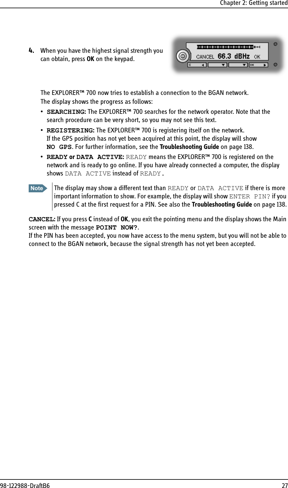
Thrane and Thrane A S EXPLORER-700 INMARSAT TERMINAL User Manual Explorer700
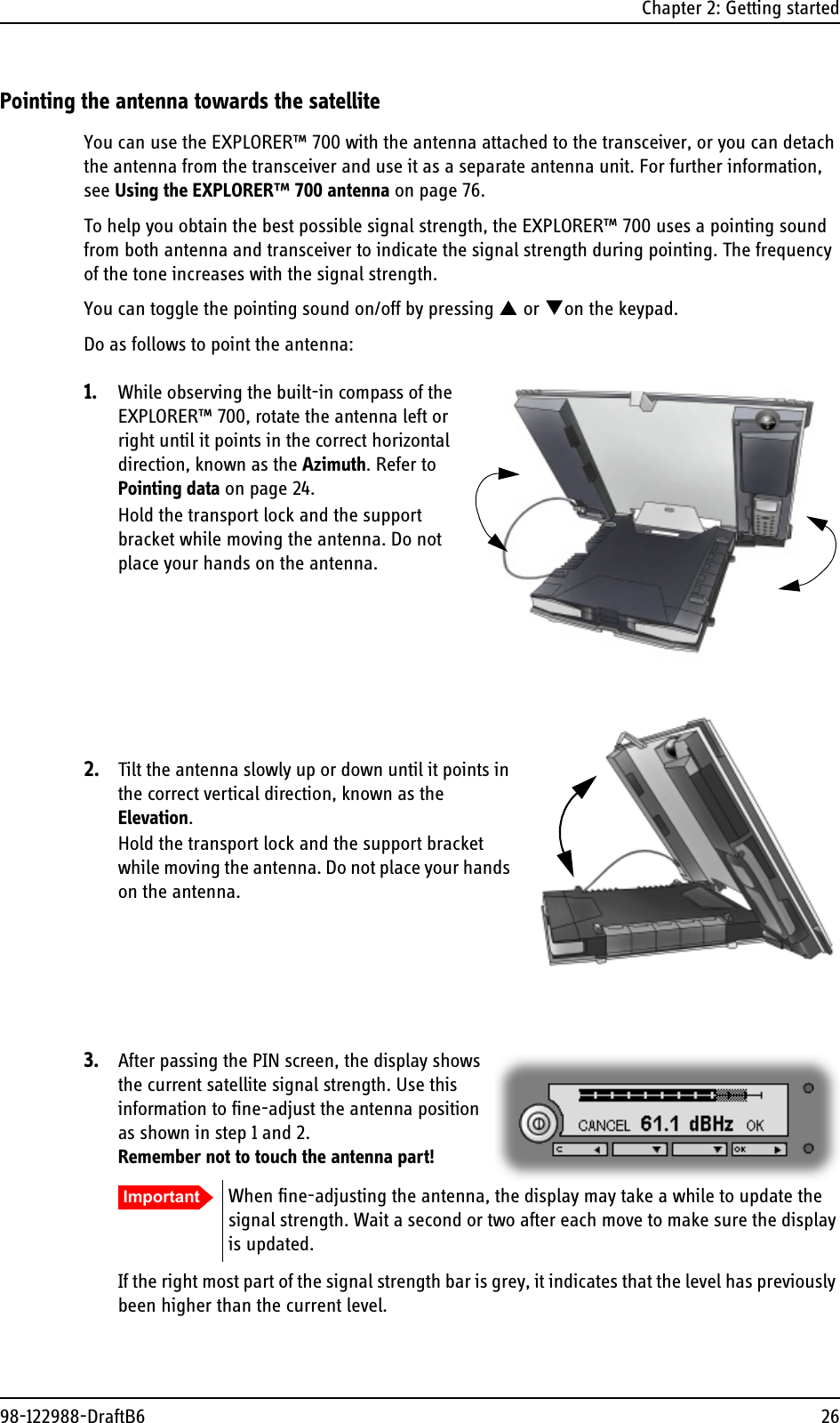
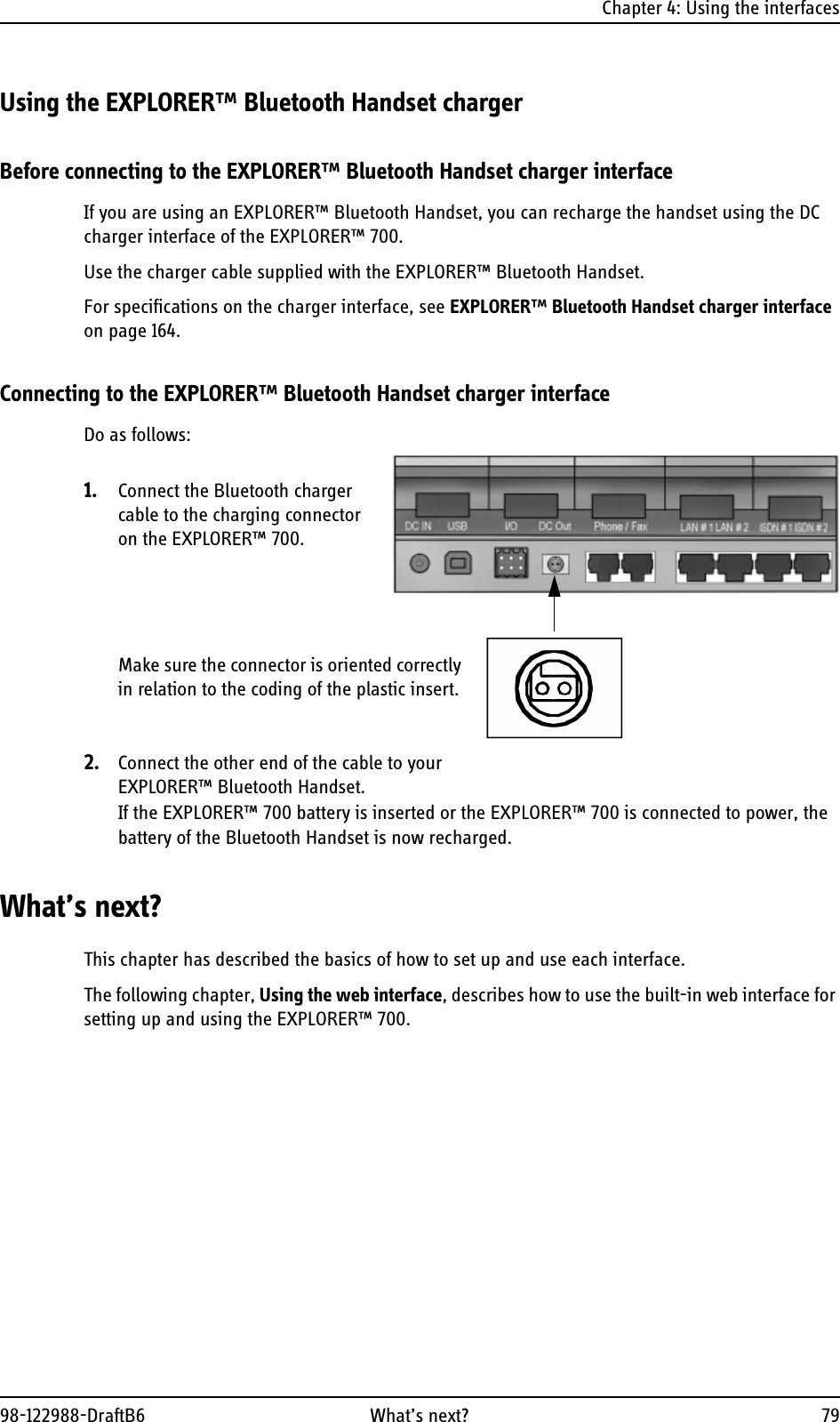
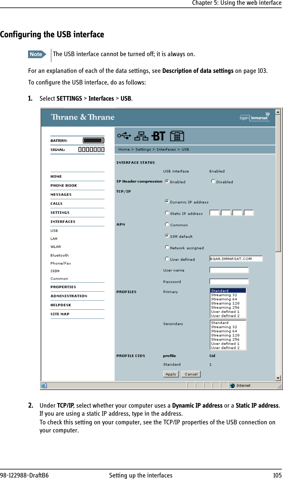
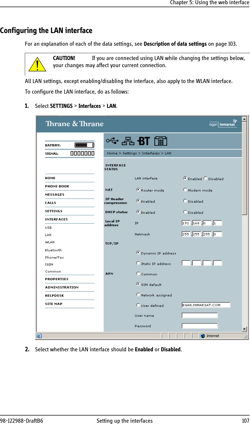
Thrane & Thrane A/S INMARSAT TERMINAL Explorer700
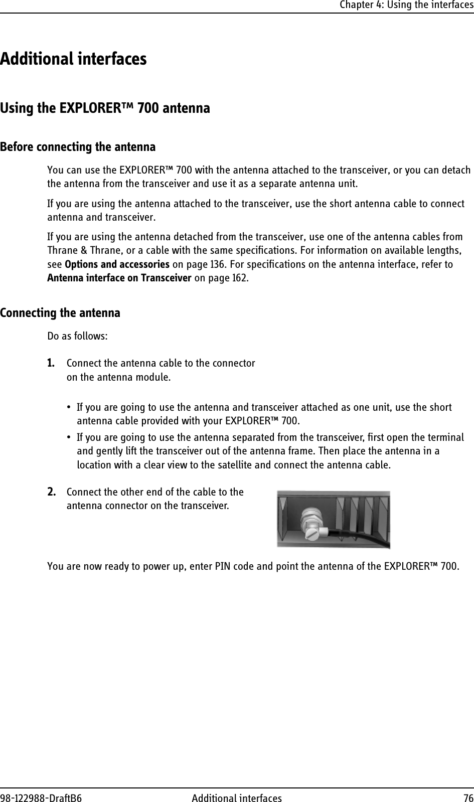
UserManual.wiki
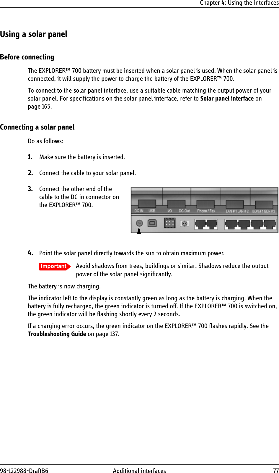
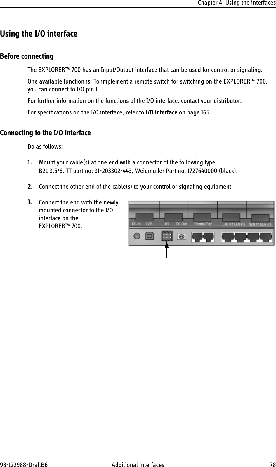
>
Thrane and Thrane A S
>
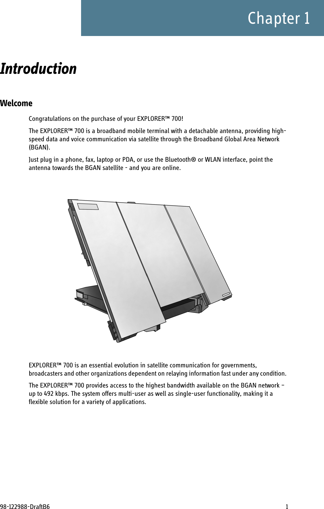
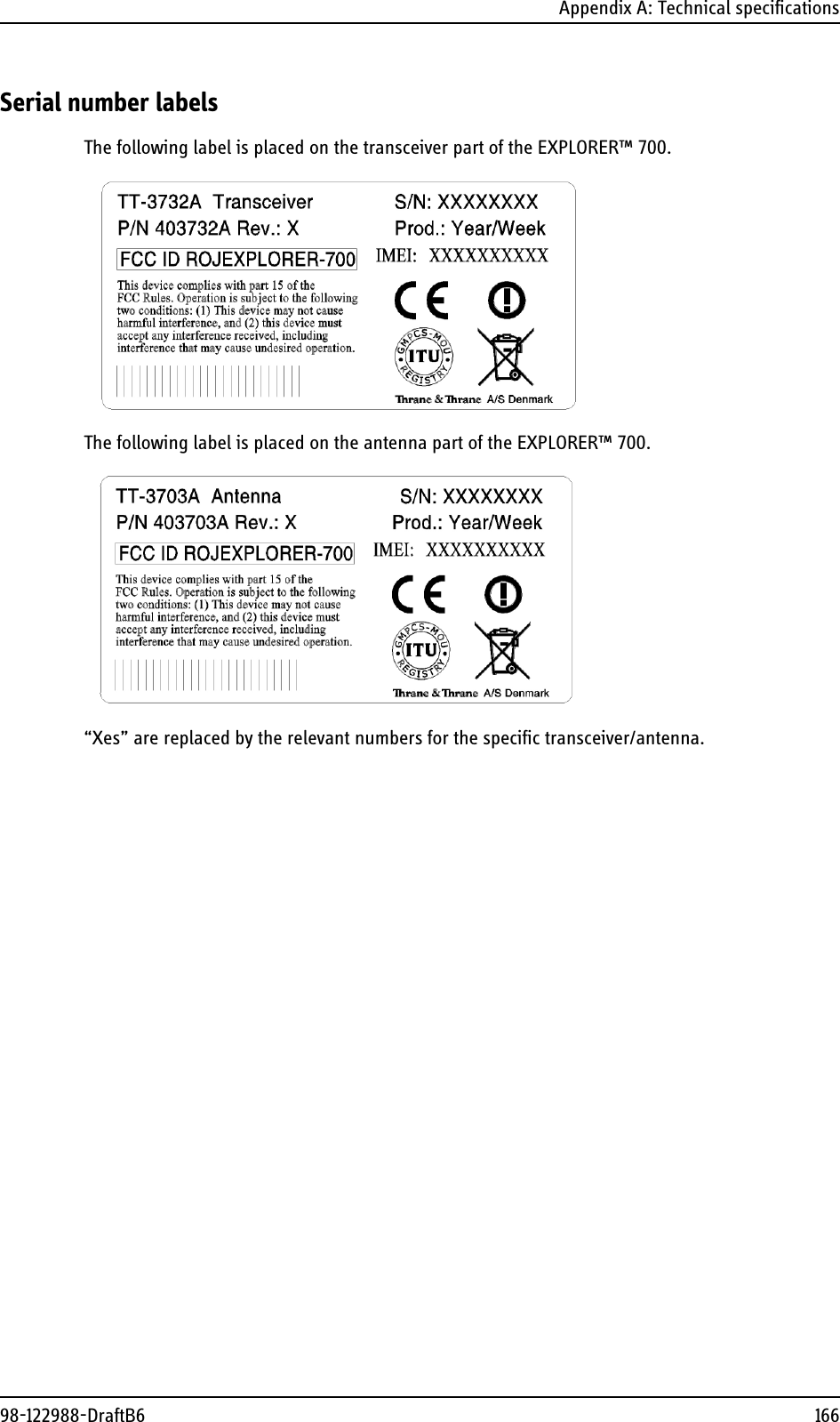
EXPLORER 700 User Manual
USERS MANUAL
Navigation menu
Upload a User Manual
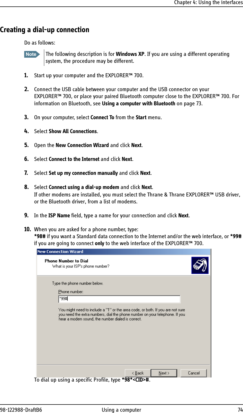
Namespaces
Wiki Guide
HTML
PDF
Info
Views
User Manual
Discussion / Help
Navigation
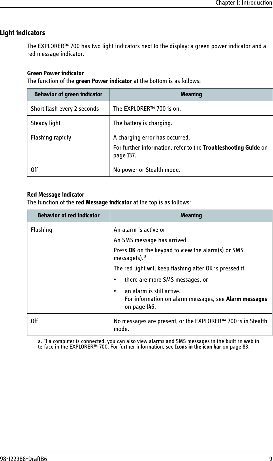
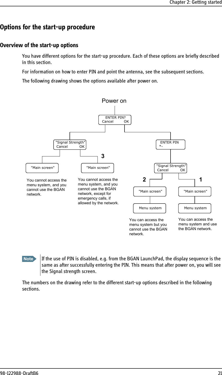
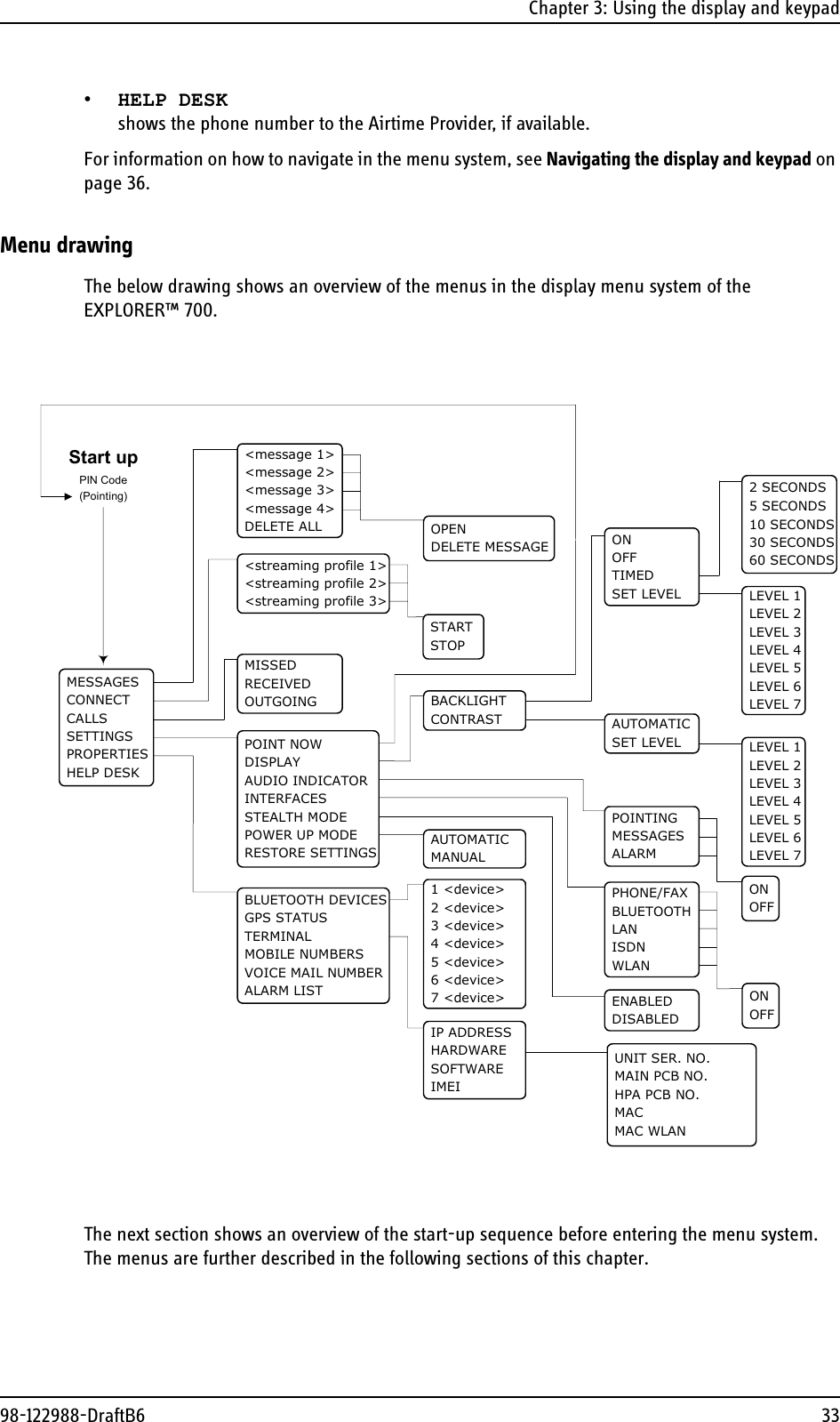
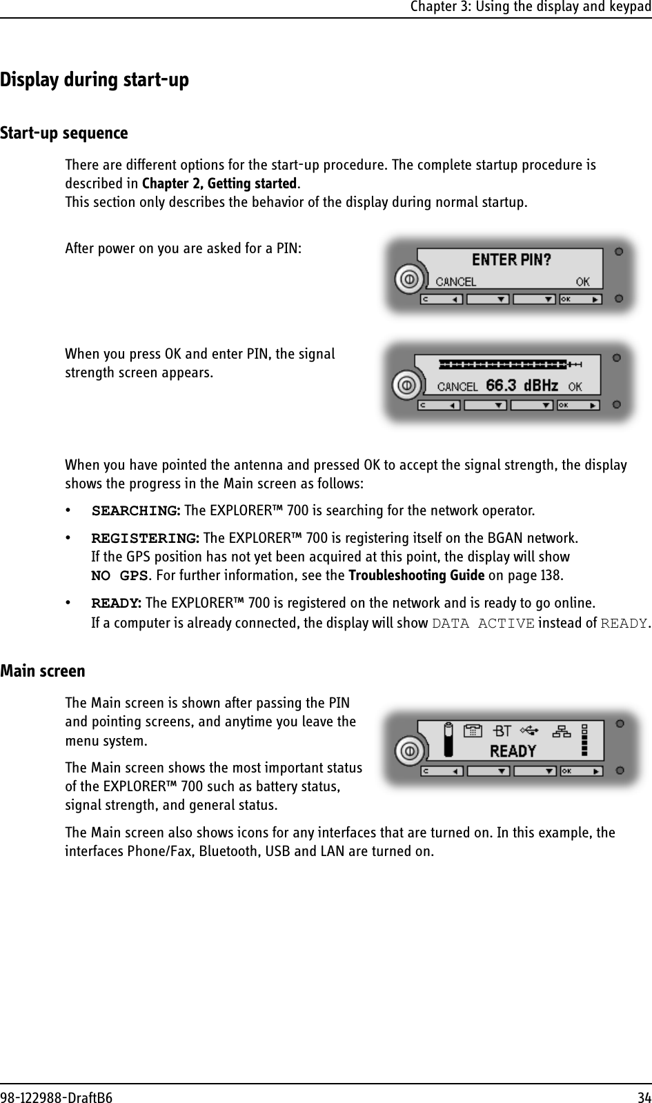
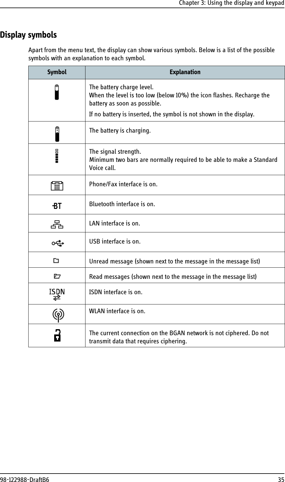
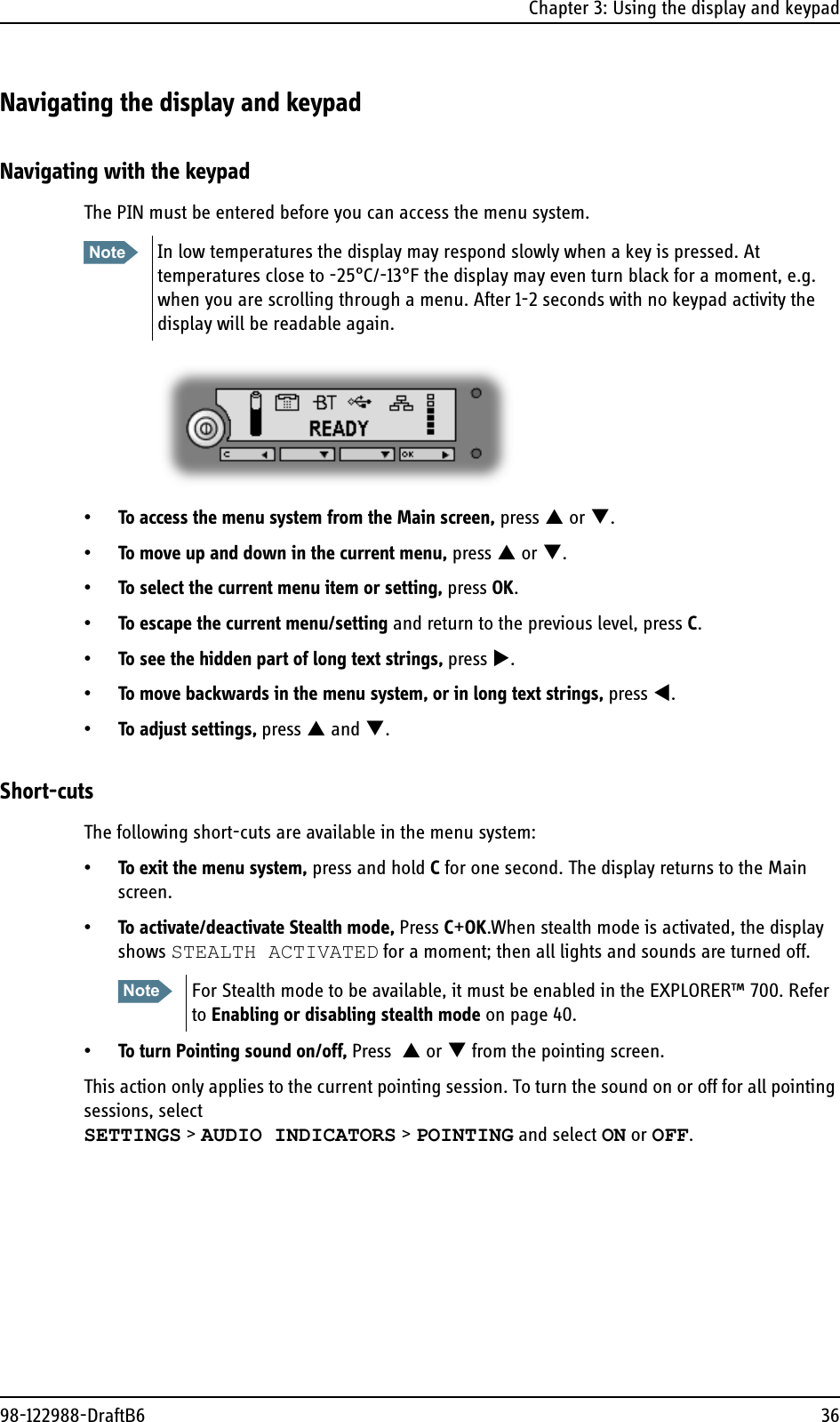
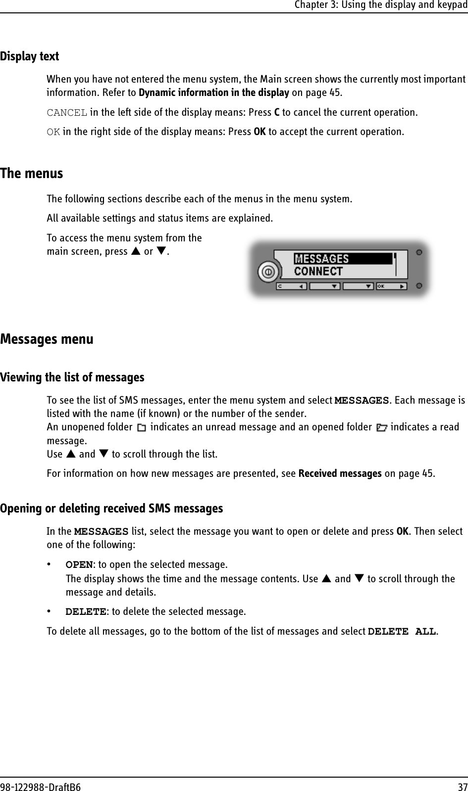
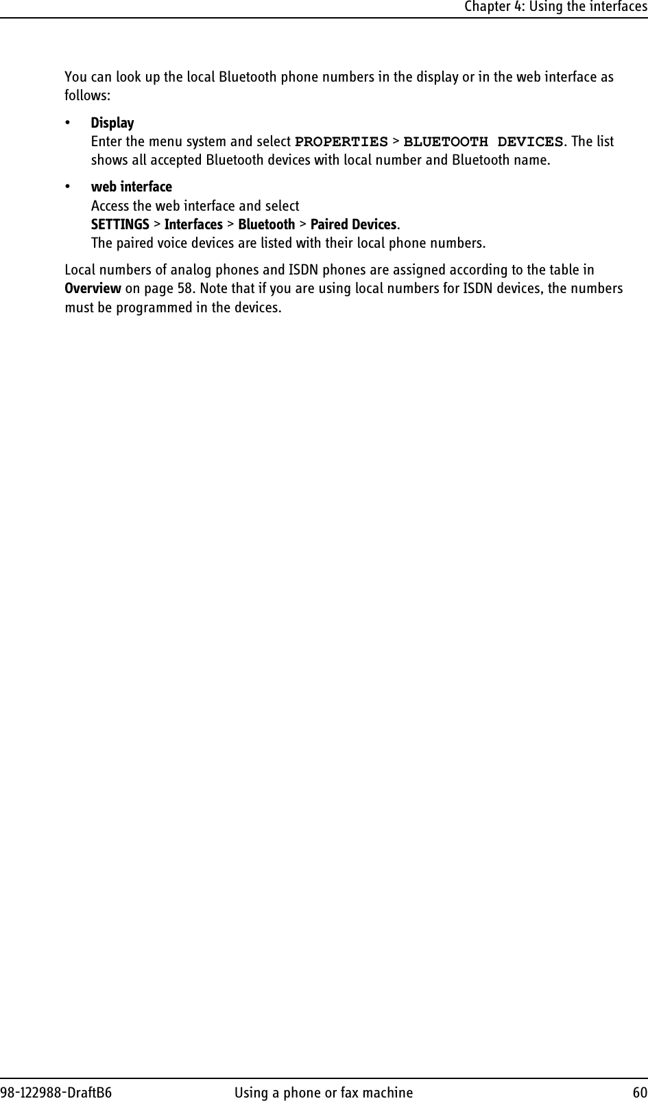
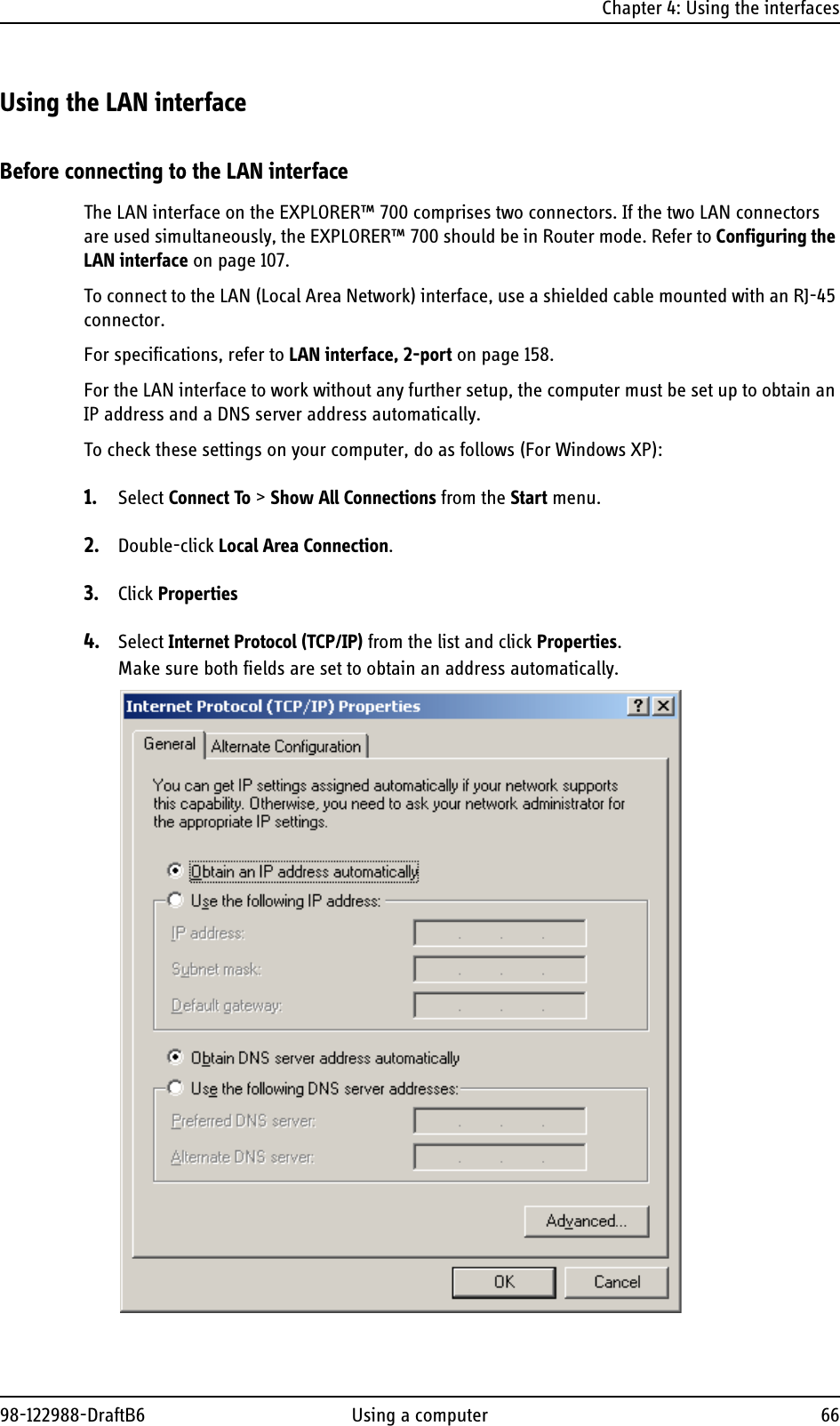
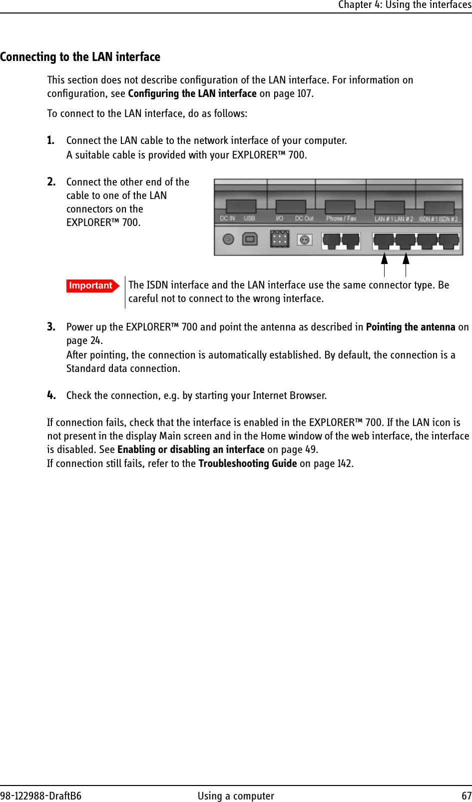
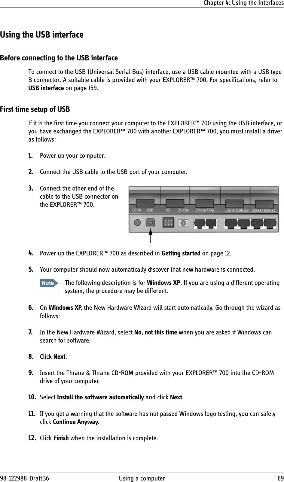
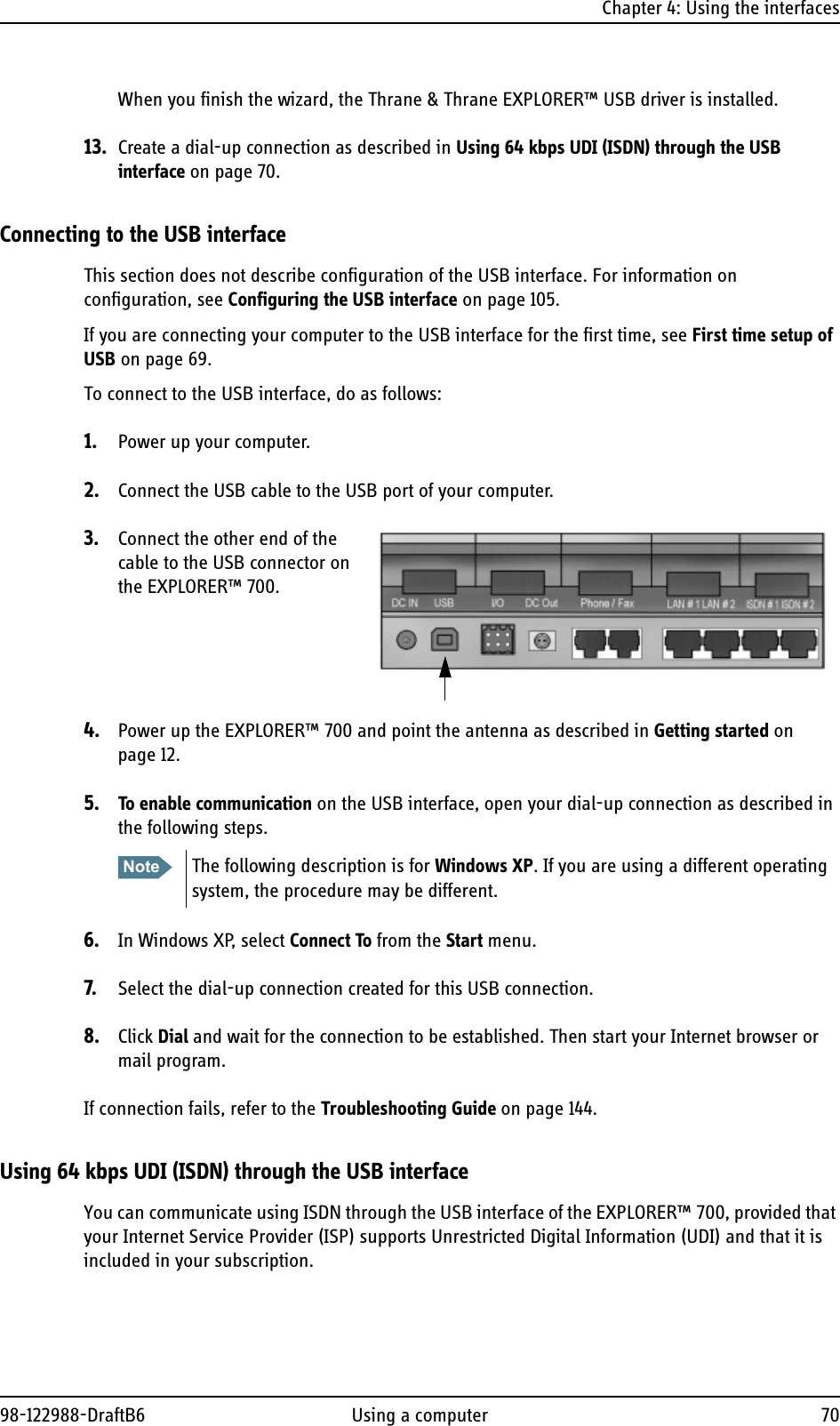
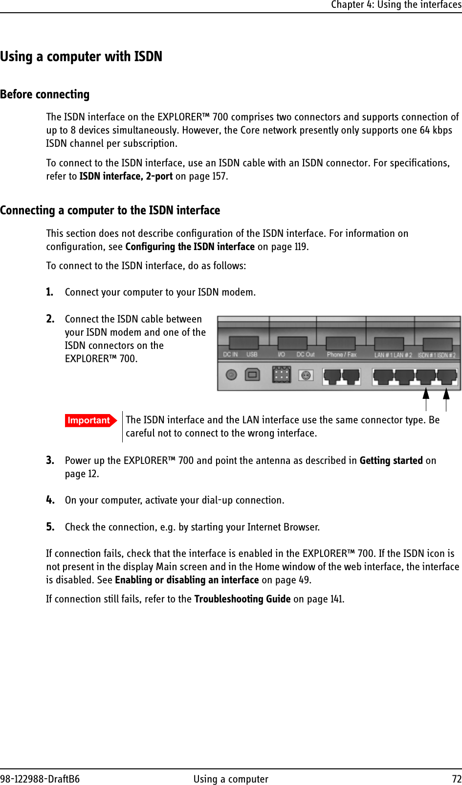
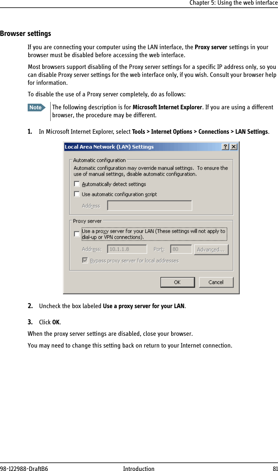
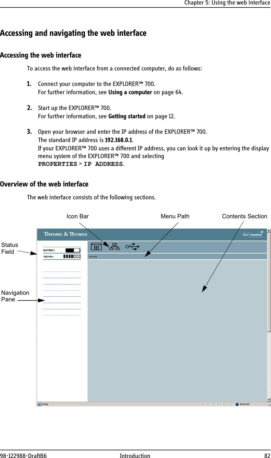
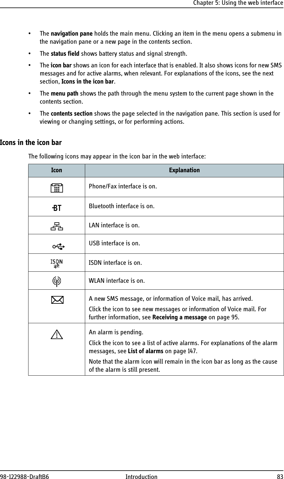
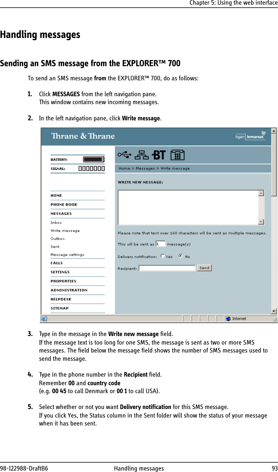
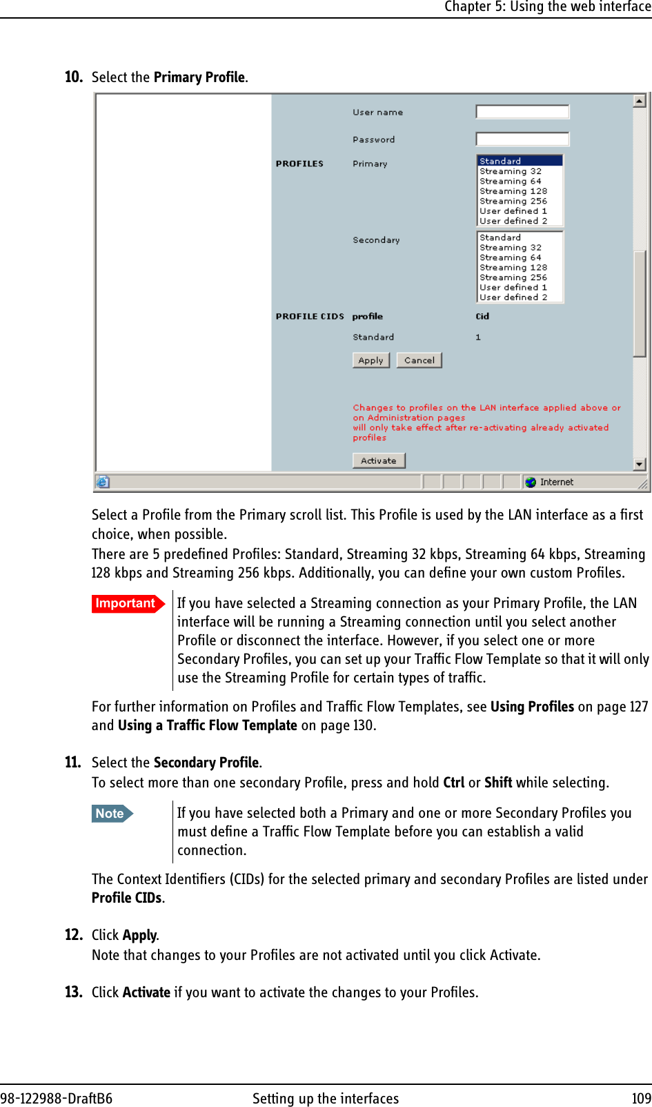
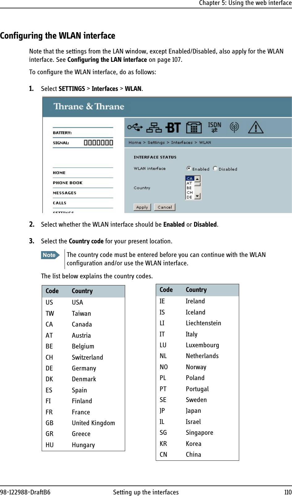
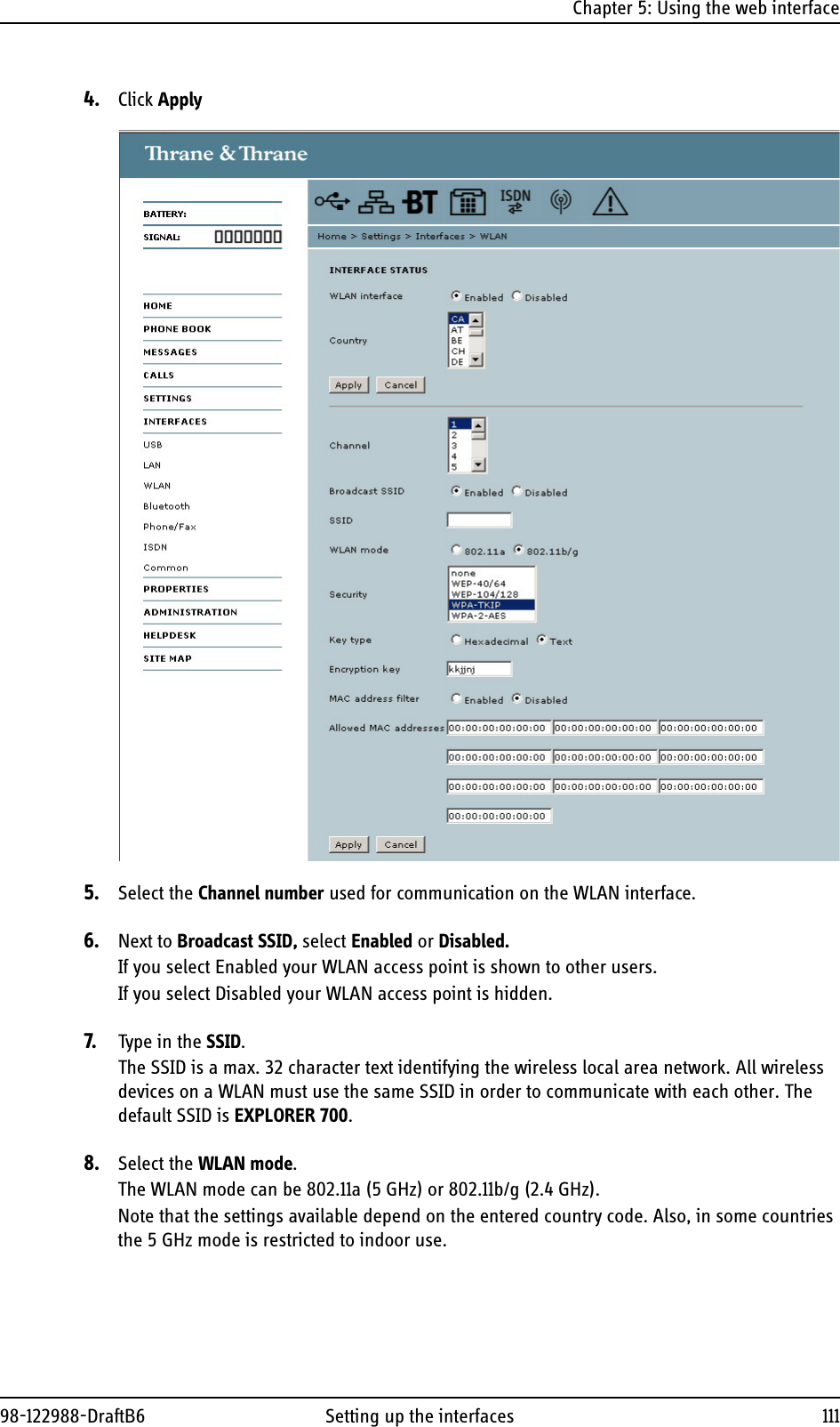
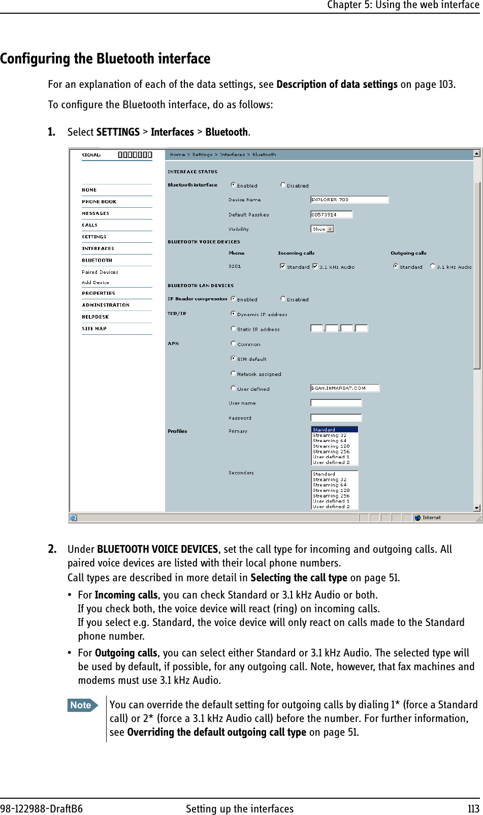

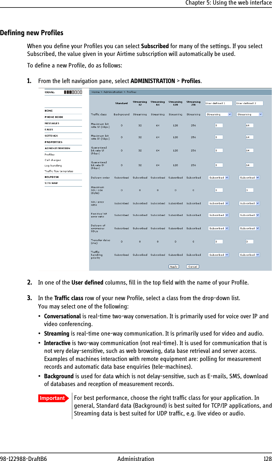

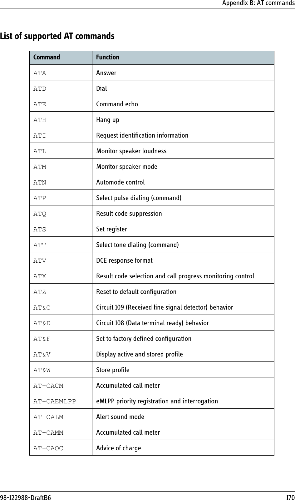
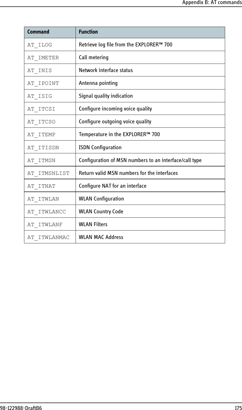
![Appendix B: AT commands98-122988-DraftB6 174AT+CSIL Silence commandAT+CSMS Select message serviceAT+CSQ Signal qualityAT+CSSN Supplementary service notificationsAT+CSTA Select type of addressAT+CSTF Settings time formatAT+CSVM Set voice mail numberAT+CUSD Unstructured supplementary service dataAT+CAAP Automatic answer for eMLPP ServiceAT+FCLASS Select modeAT+GCAP Request complete capabilities listAT+GCI Country of InstallationAT+GMI Request manufacturer identificationAT+GMM Request model identificationAT+GMR Request revision identificationAT+GSN Request product serial number identificationAT+ICF DTE DCE character framingAT+IFC DTE-DCE local flow controlAT+ILRR DTE-DCE local rate reportingAT+IPR Fixed DTE rateAT+WS46 PCCA STD-101 [17] select wireless networkAT_IBLTH Bluetooth managementAT_IBNOTIFY Control the sending of unsolicited result codesAT_IBTIF Bluetooth configurationAT_IBTINQ Bluetooth inquiry managementAT_IGPS GPS location informationCommand Function](https://usermanual.wiki/Thrane-and-Thrane-A-S/EXPLORER-700/User-Guide-901661-Page-184.png)