Thrane and Thrane A S EXPLORER-710 TT-3720B Land-portable broadband terminal for Inmarsat satellite system Consists of TT-3732B Transceiver and TT-3703B Antenna User Manual E710
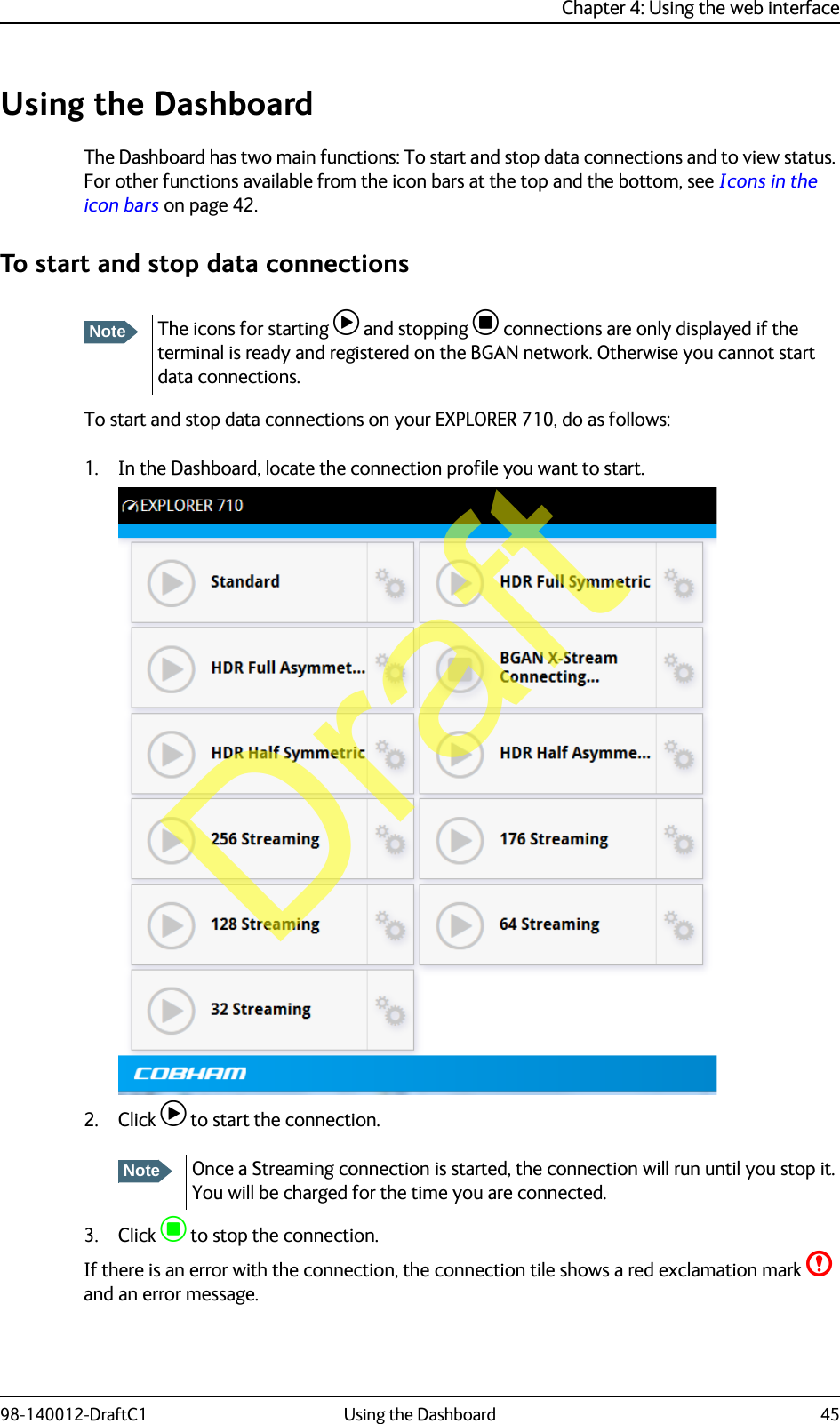
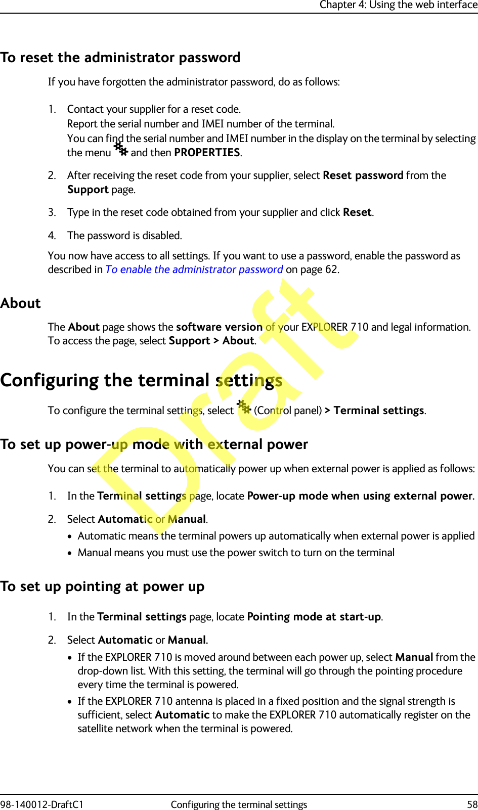
Thrane & Thrane A/S TT-3720B Land-portable broadband terminal for Inmarsat satellite system Consists of TT-3732B Transceiver and TT-3703B Antenna E710
User Manual
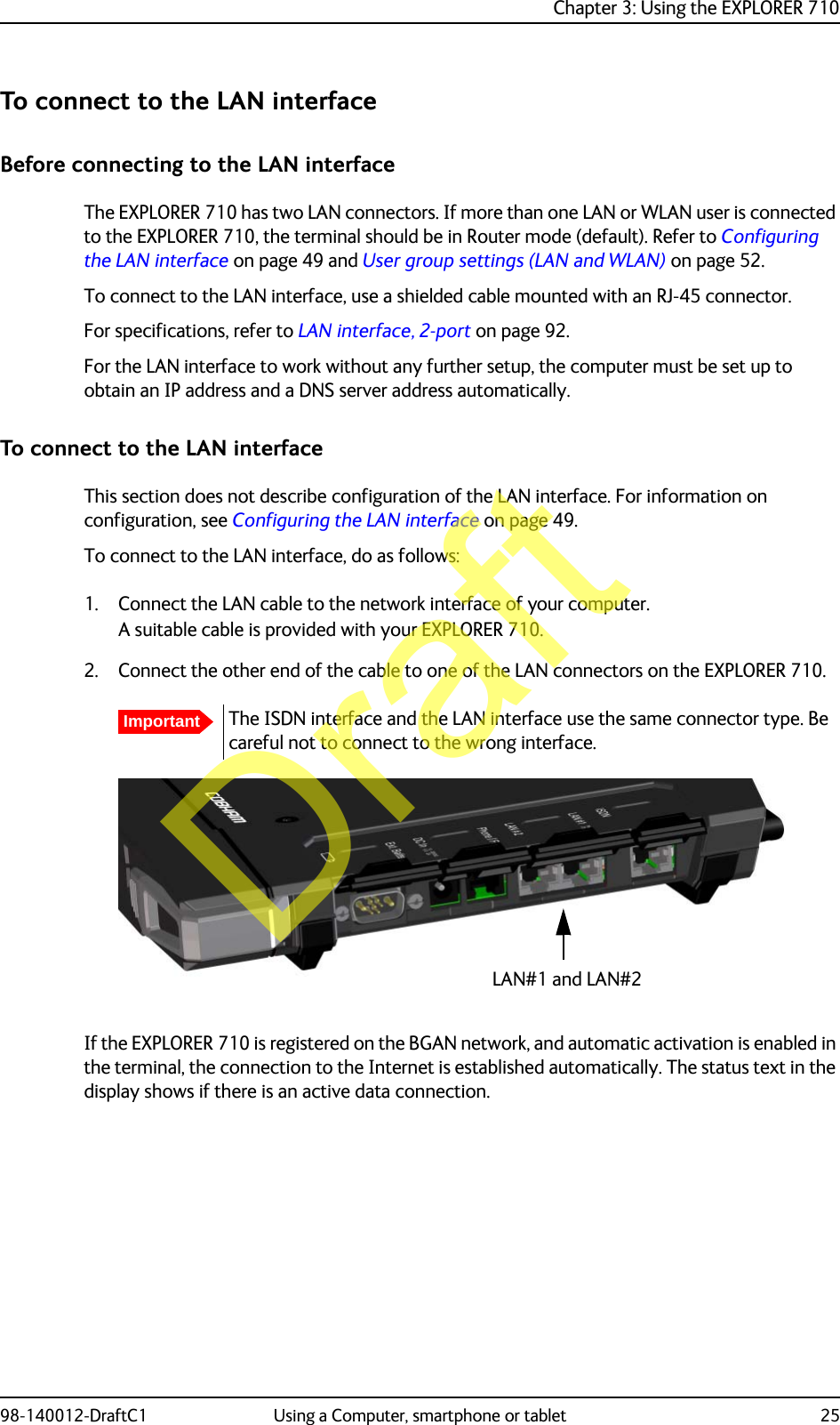
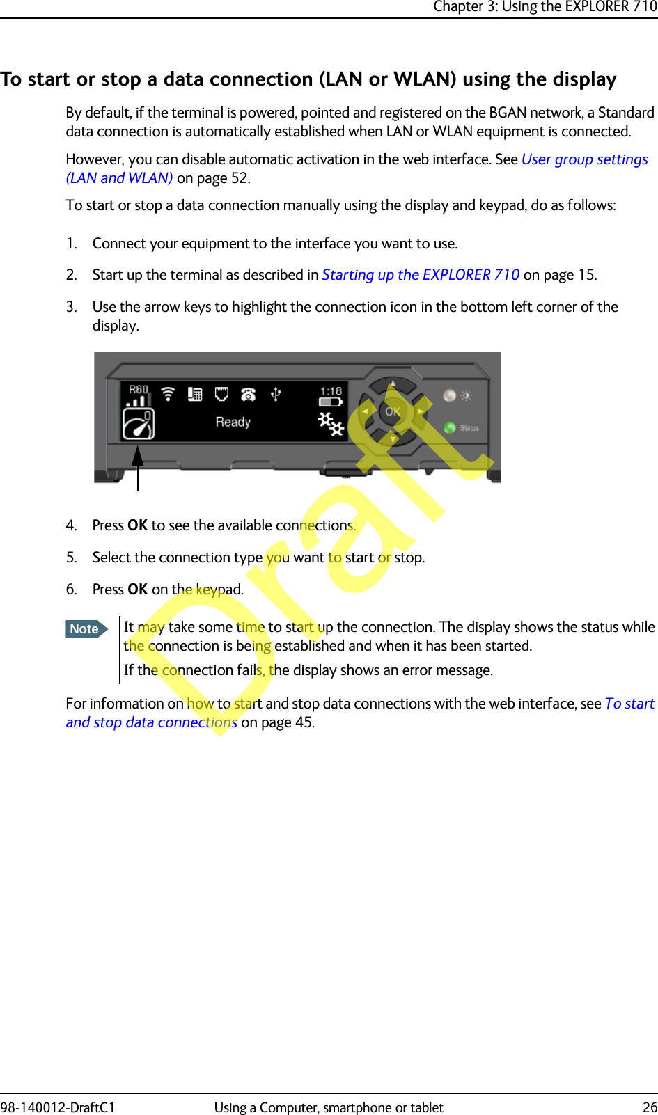
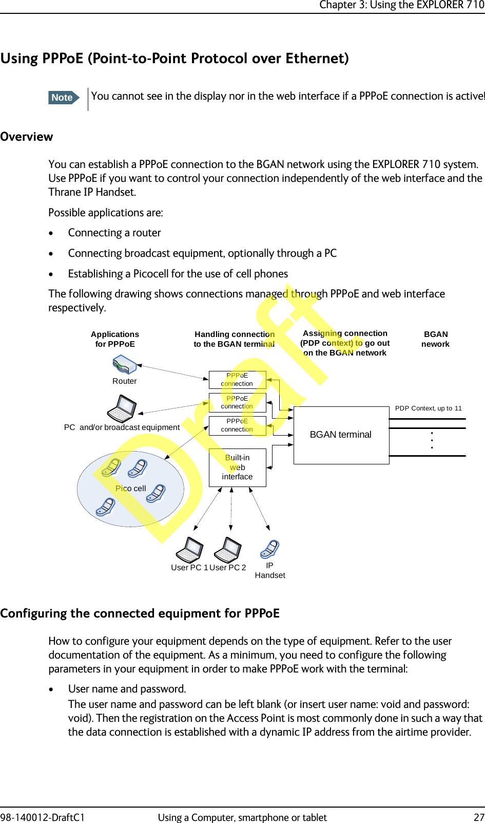
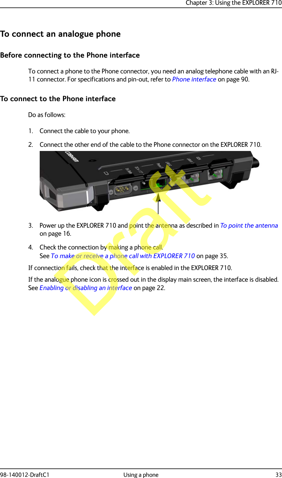
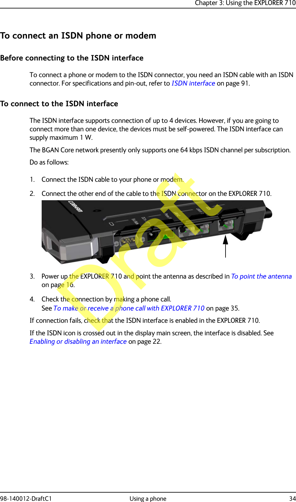
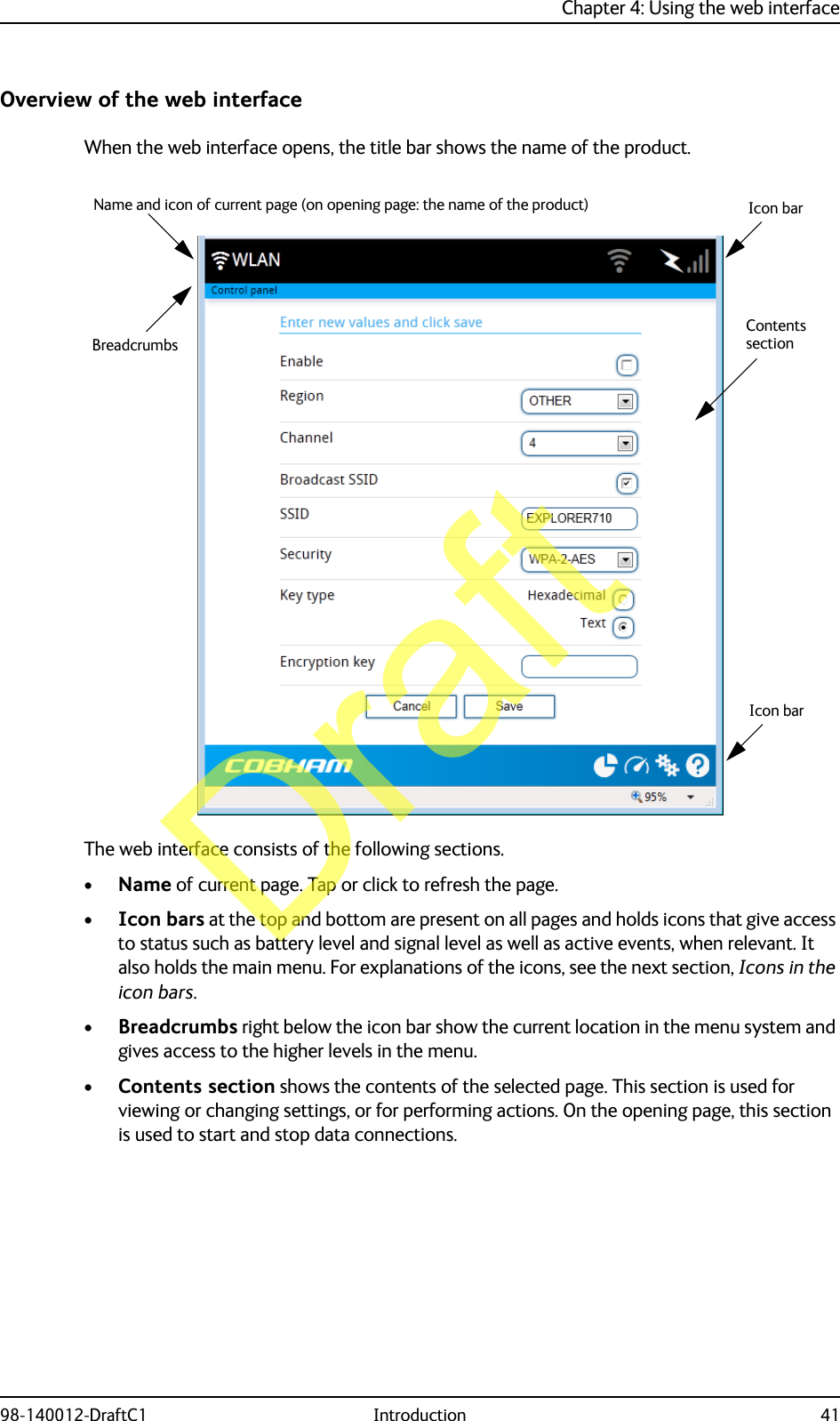

![98-140012-DraftC1 96Appendix BConformity BGeneralApprovals for the EXPLORER 710 are listed in the display menu of the EXPLORER 710 terminal. Select and then Properties > Conformity.CE (R&TTE)The EXPLORER 710 is CE certified (R&TTE directive) as stated in “Declaration of Conformity with R&TTE Directive”, enclosed in electronic copy on the next page. The WLAN interface is CE certified through the manufacturer of the WLAN card.Use of WLAN:The WLAN interface requires that the user enters the current country of operation. See Configuring the WLAN interface on page 50.For use in the EU, the following restrictions apply:• France: Outdoor use must be limited to 10 mW EIRP within the frequency band 2454 MHz to 2483.5 MHz.• Italy: Outdoor use outside own premises require general authorization.ICThis device complies with Industry Canada licence-exempt RSS standard(s). Operation is subject to the following two conditions: (1) this device may not cause interference, and (2) this device must accept any interference, including interference that may cause undesired operation of the device.Le présent appareil est conforme aux CNR d'Industrie Canada applicables aux appareils radio exempts de licence. L'exploitation est autorisée aux deux conditions suivantes : (1) l'appareil ne doit pas produire de brouillage, et (2) l'utilisateur de l'appareil doit accepter tout brouillage radioélectrique subi, même si le brouillage est susceptible d'en compromettre le fonctionnement.This Class [B] digital apparatus complies with Canadian ICES-003.Cet appareil numérique de la classe [B] est conforme à la norme NMB-003 du Canada.WLAN:Under Industry Canada regulations, this radio transmitter may only operate using an antenna of a type and maximum (or lesser) gain approved for the transmitter by Industry Canada. To reduce potential radio interference to other users, the antenna type and its gain should be so chosen that the equivalent isotropically radiated power (e.i.r.p.) is not more than that necessary for successful communication.Draft](https://usermanual.wiki/Thrane-and-Thrane-A-S/EXPLORER-710/User-Guide-2287875-Page-107.png)