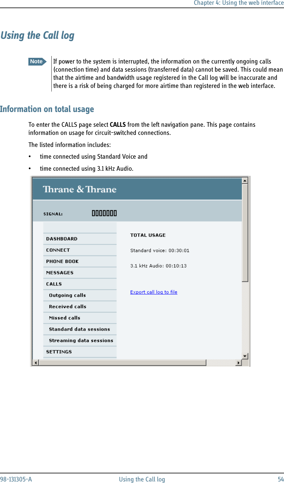
Thrane and Thrane A S EXPLORER325 EXPLORER 325 landmobile broadband terminal for Inmarsat satellite system User Manual BGAN X UM
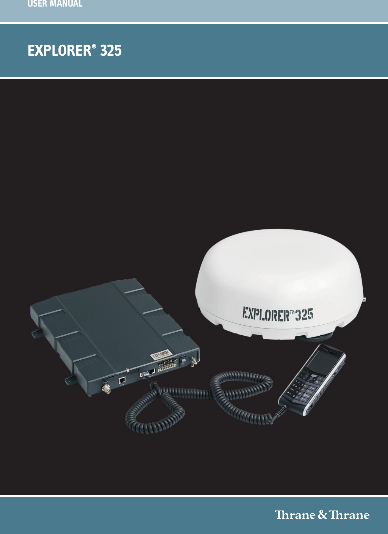
Thrane & Thrane A/S EXPLORER 325 landmobile broadband terminal for Inmarsat satellite system BGAN X UM
UserManual.wiki
>
Thrane and Thrane A S
>
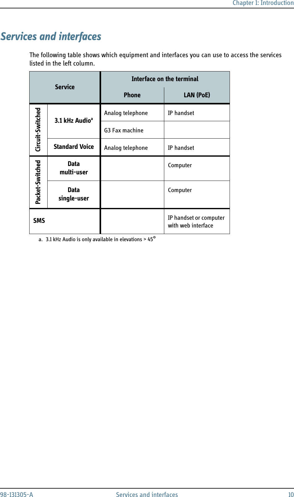
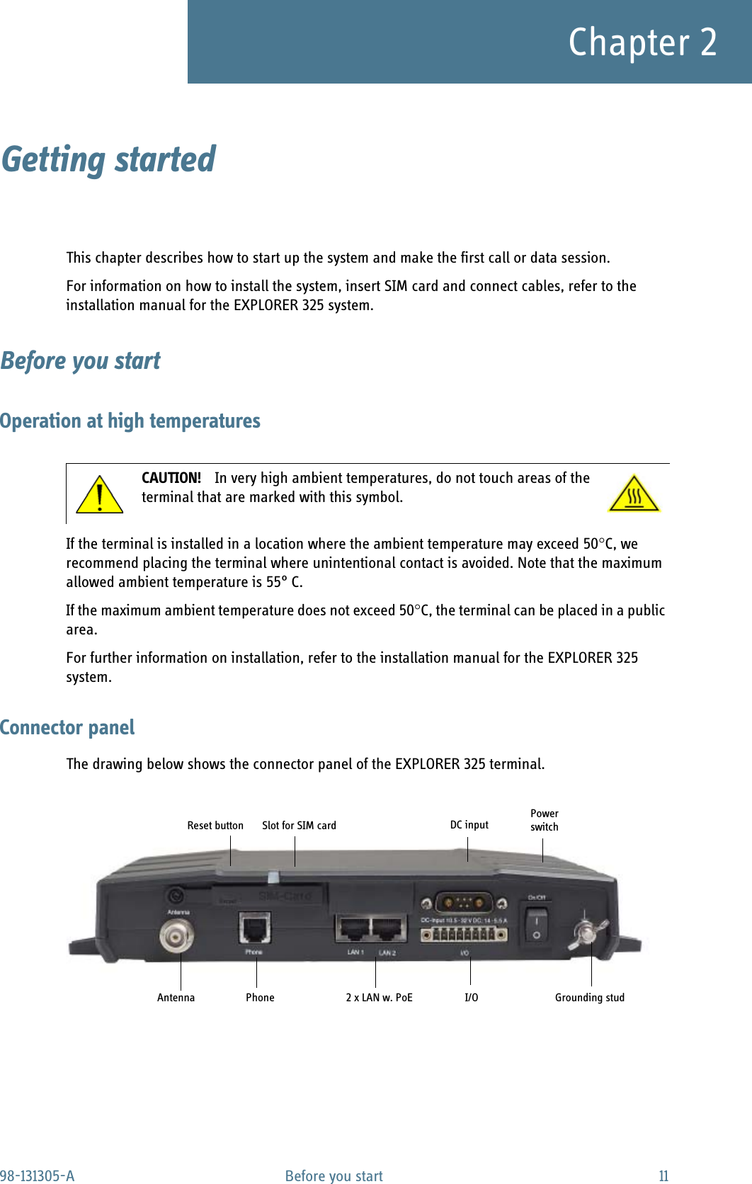
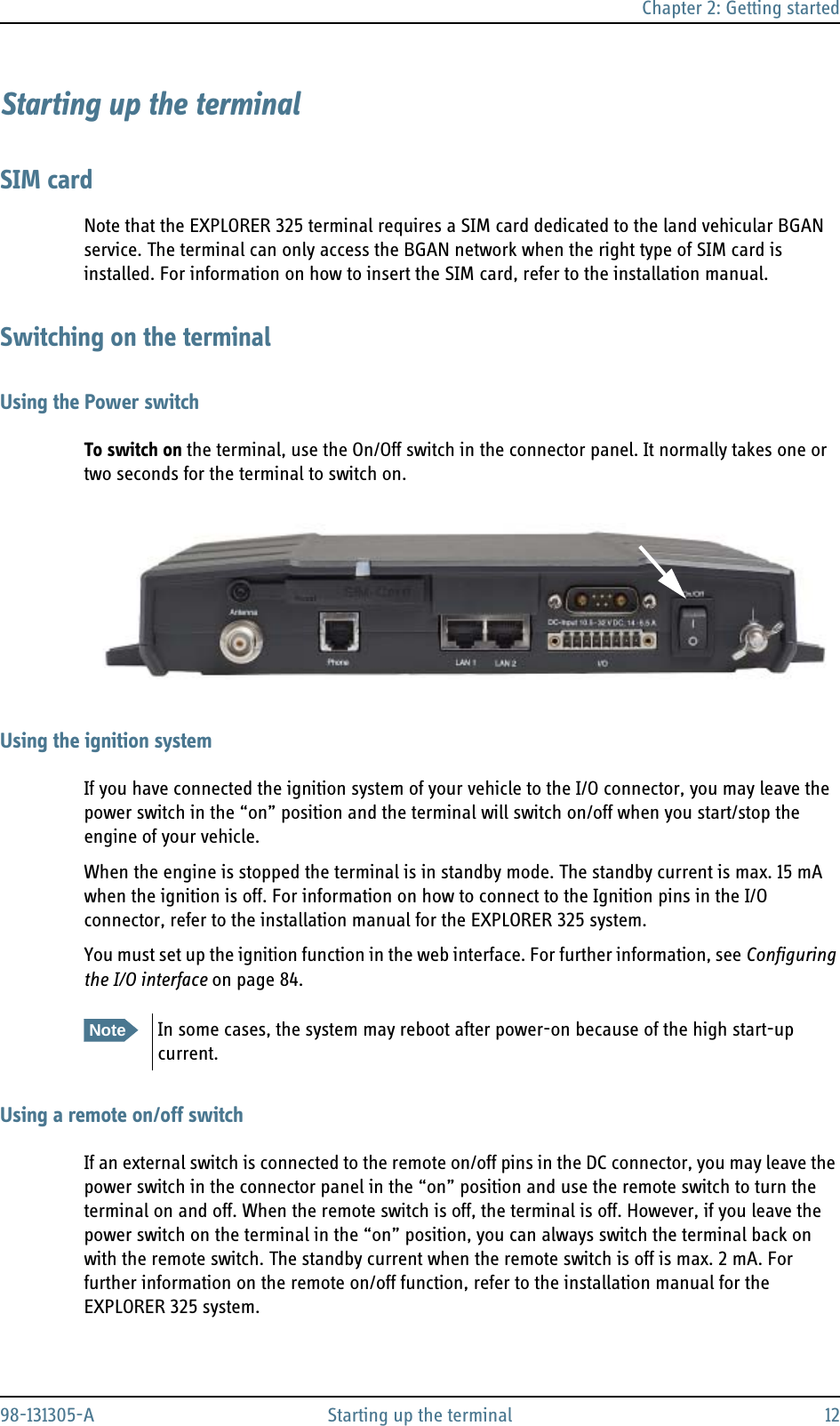
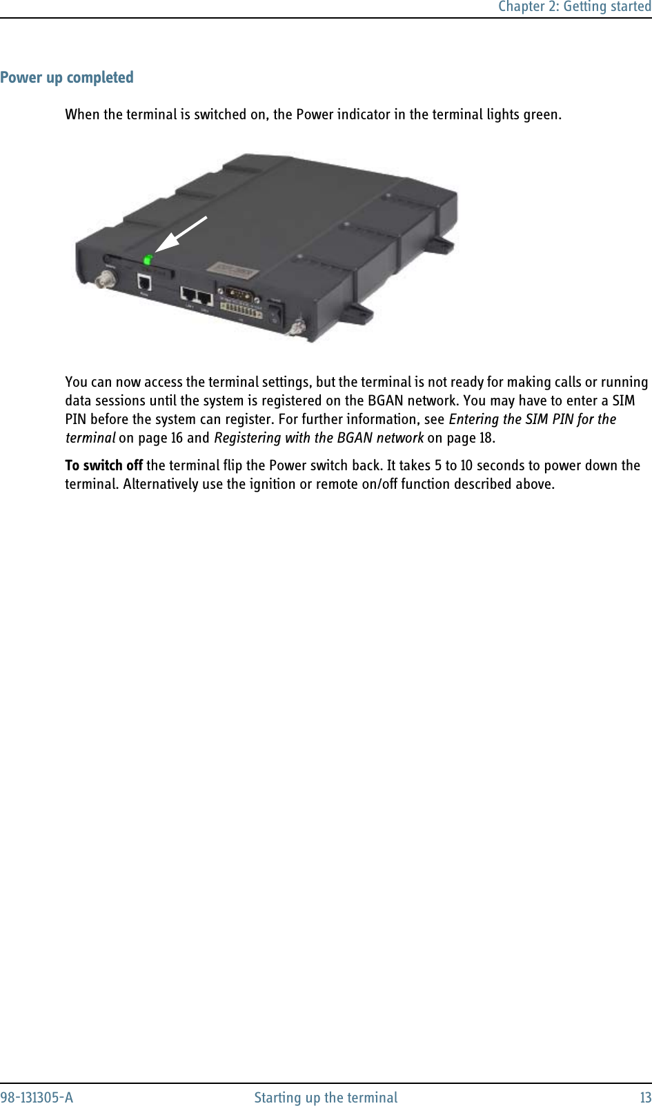
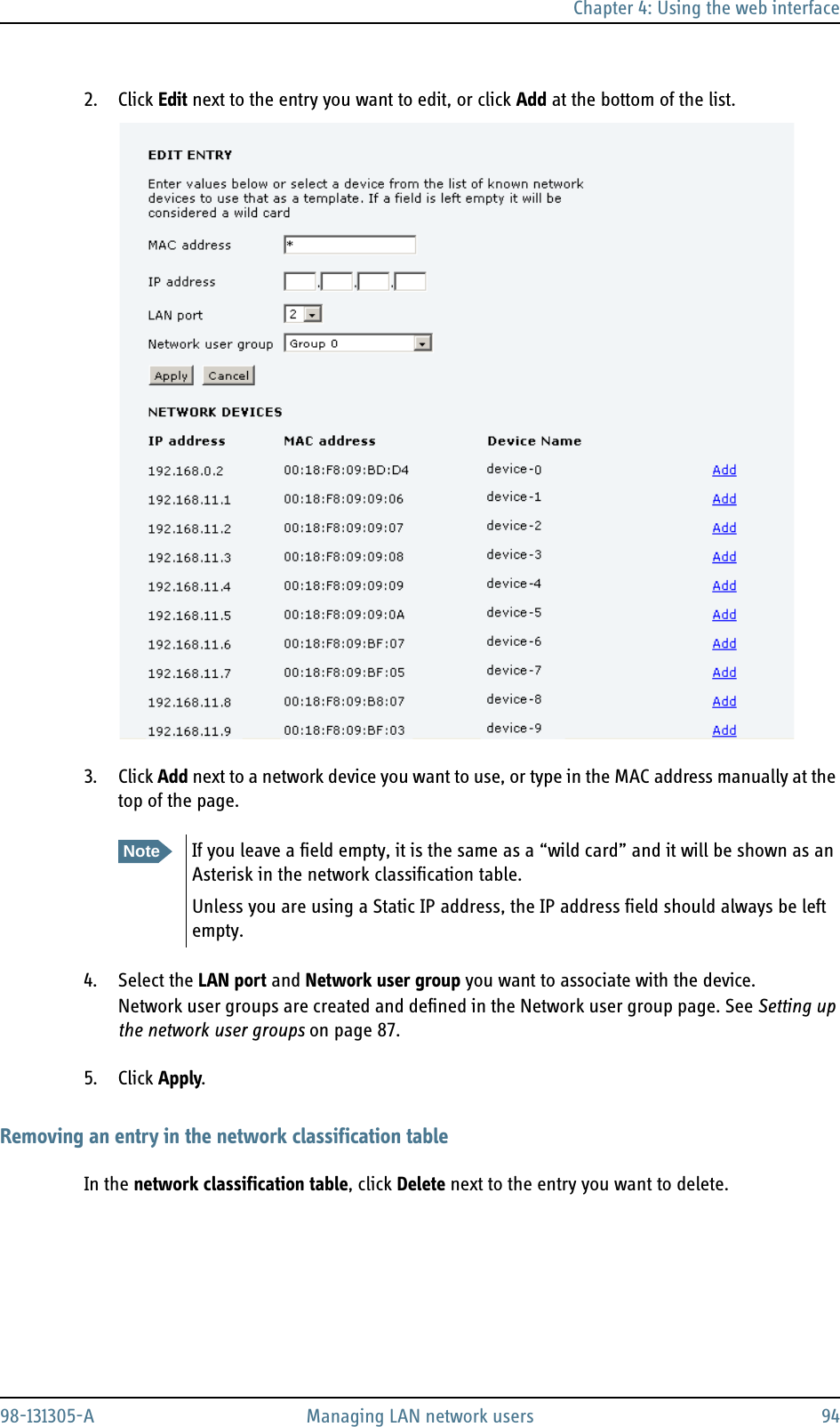
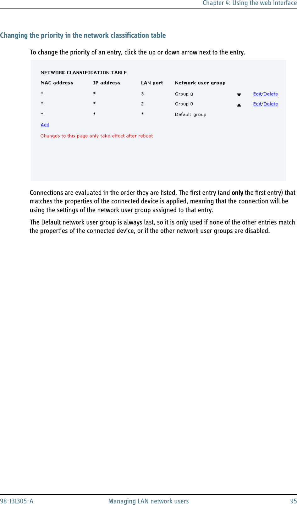
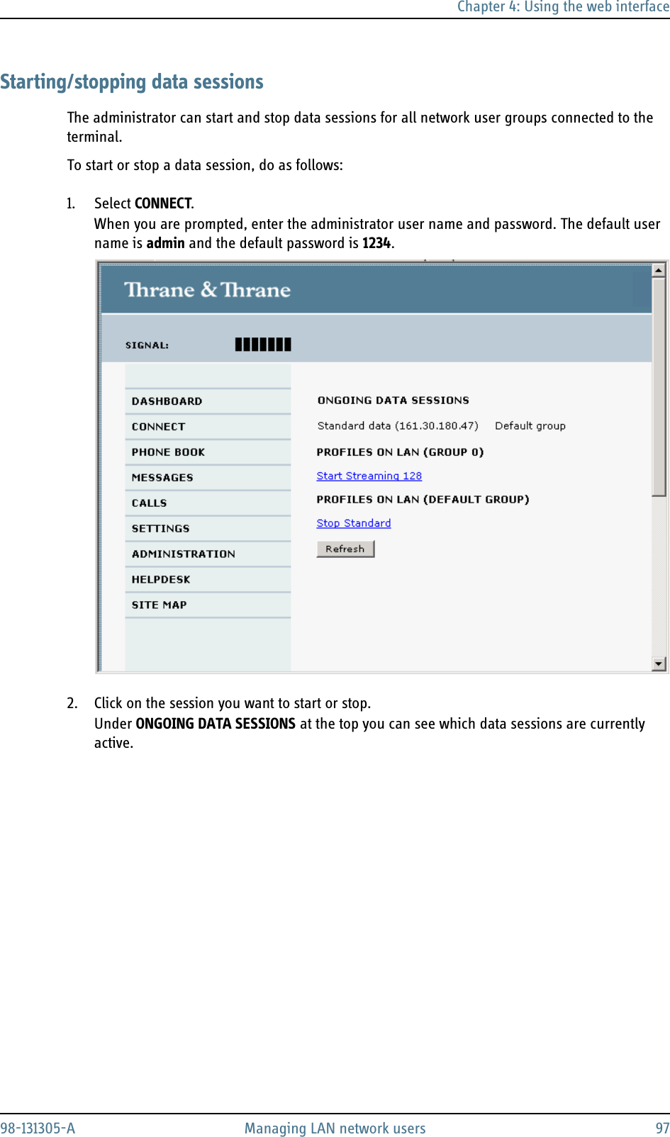
EXPLORER325 User Manual
Users manual
Navigation menu
Upload a User Manual
Namespaces
Wiki Guide
HTML
PDF
Info
Views
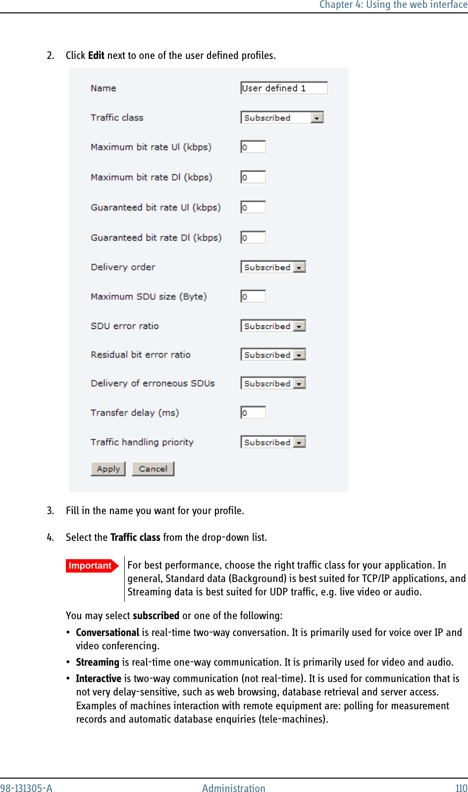
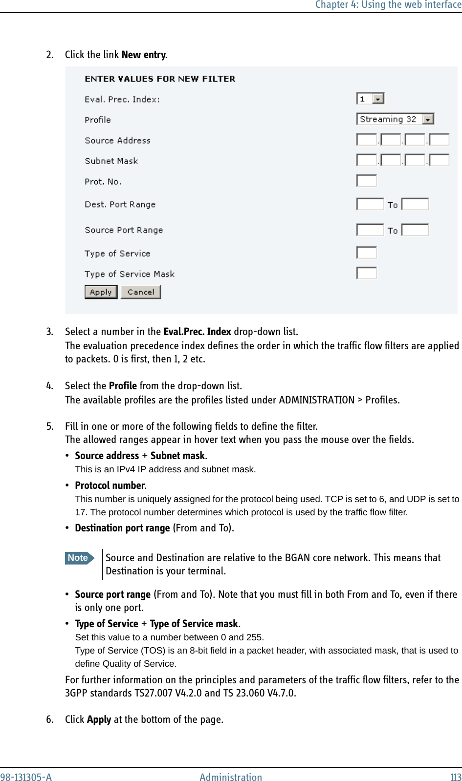
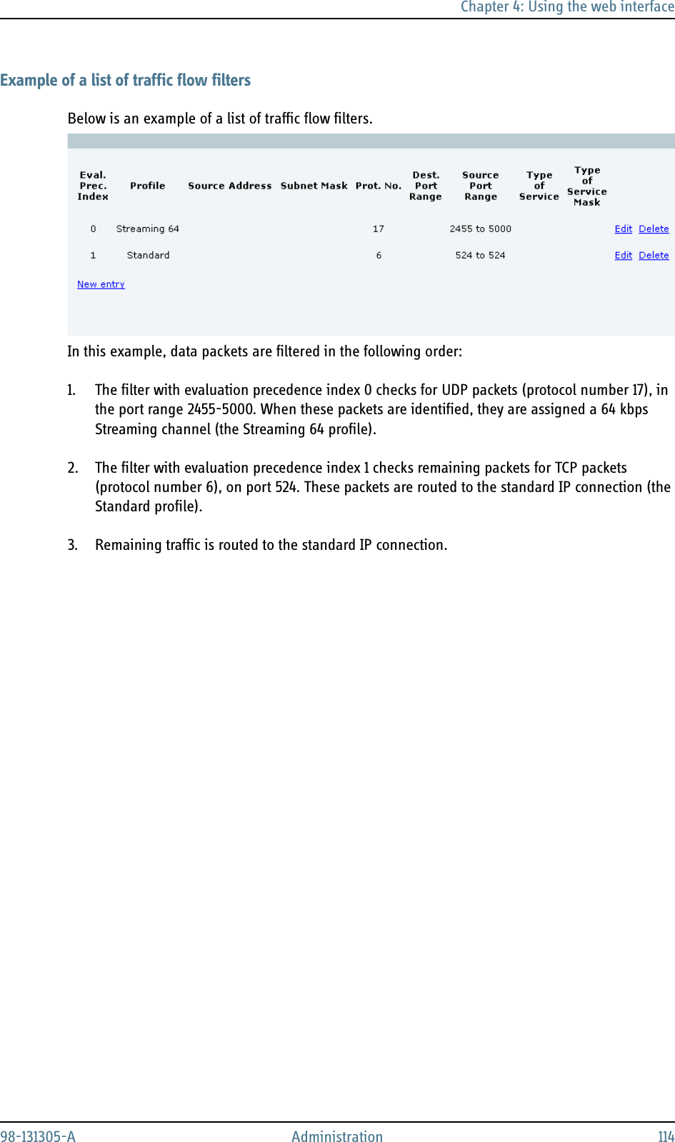
User Manual
Discussion / Help
Navigation