Thrane and Thrane A S TT-3965A SAILOR 3965 UHF Fire Fighter / McMurdo SmartFind R8F UHF Fire Fighter User Manual
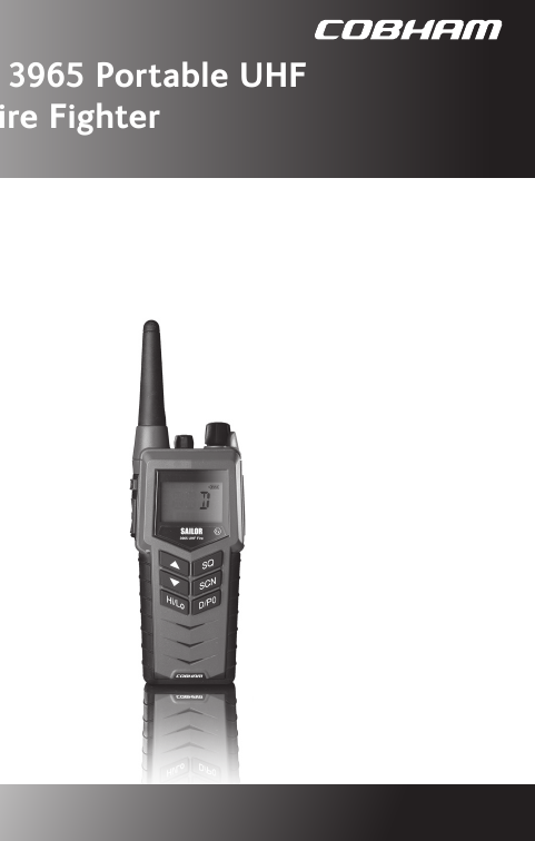
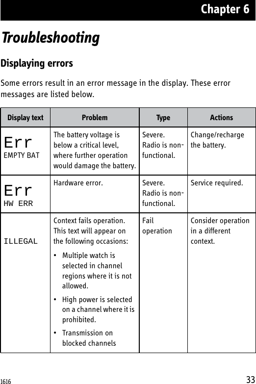
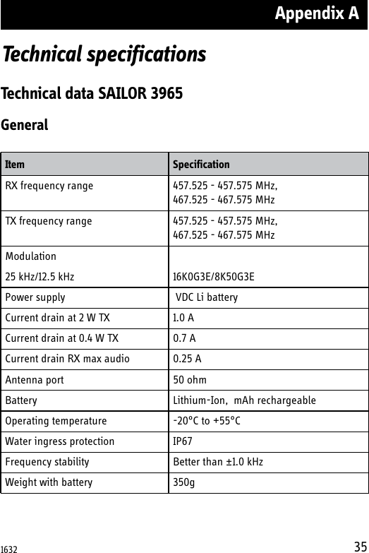
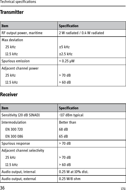
Thrane & Thrane A/S SAILOR 3965 UHF Fire Fighter / McMurdo SmartFind R8F UHF Fire Fighter
UserManual.wiki
>
Thrane and Thrane A S
>
TT 3965A User Manual
user manual
Navigation menu
Upload a User Manual
Namespaces
Wiki Guide
HTML
PDF
Info
Views
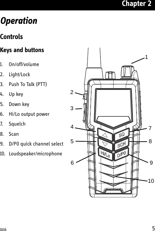
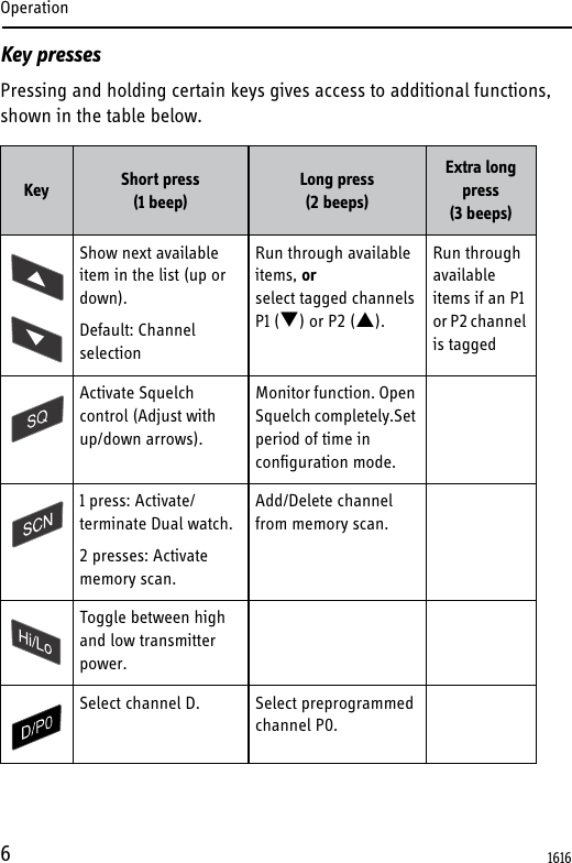
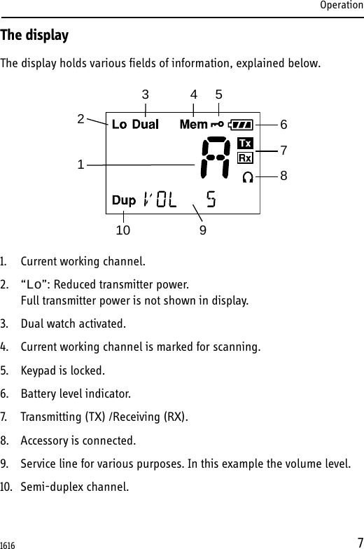
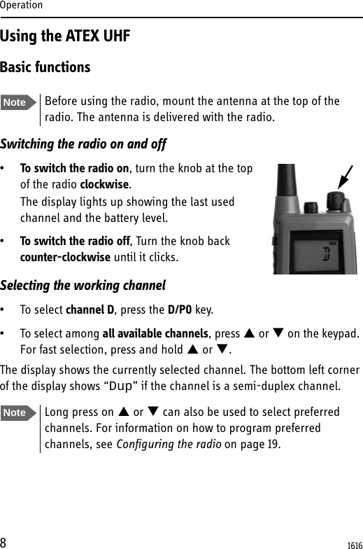
User Manual
Discussion / Help
Navigation