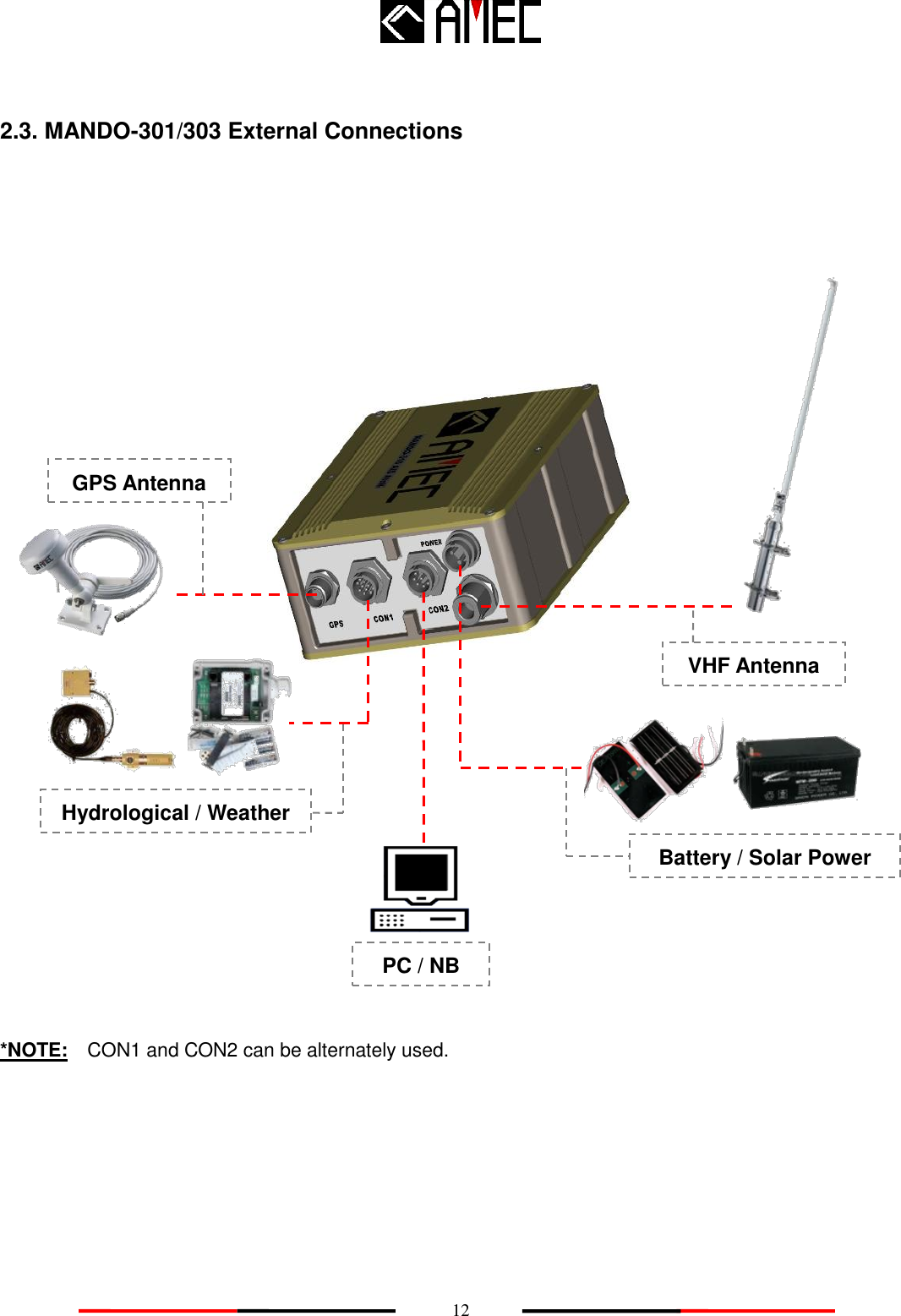
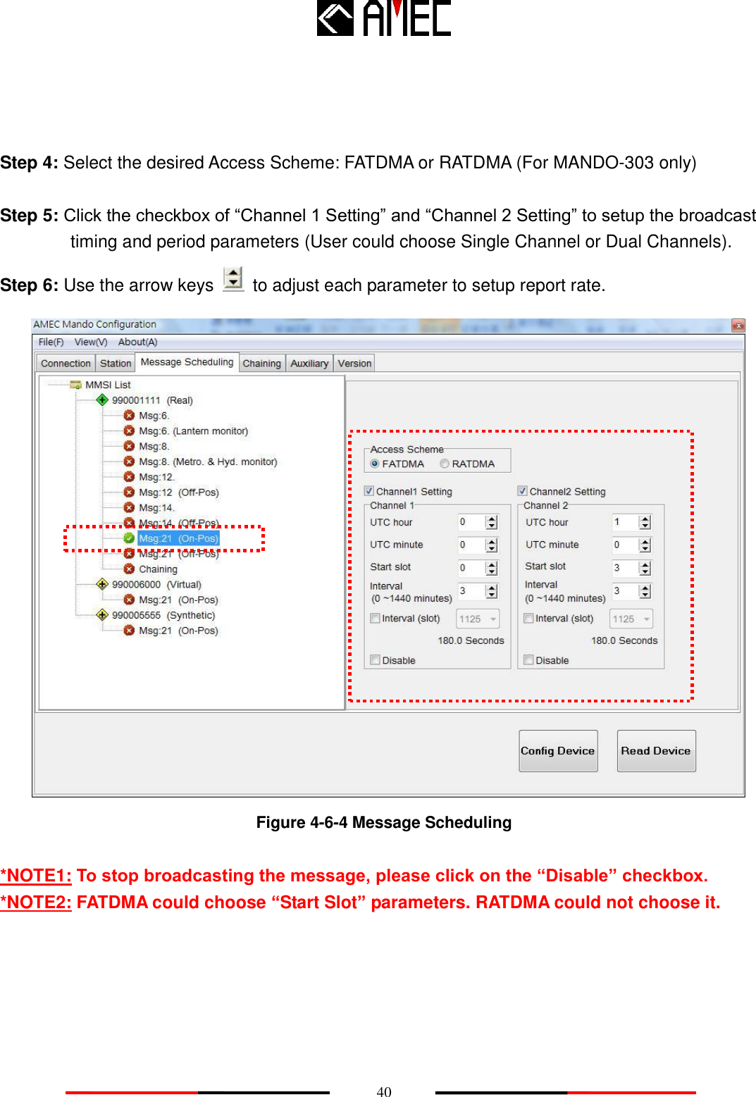
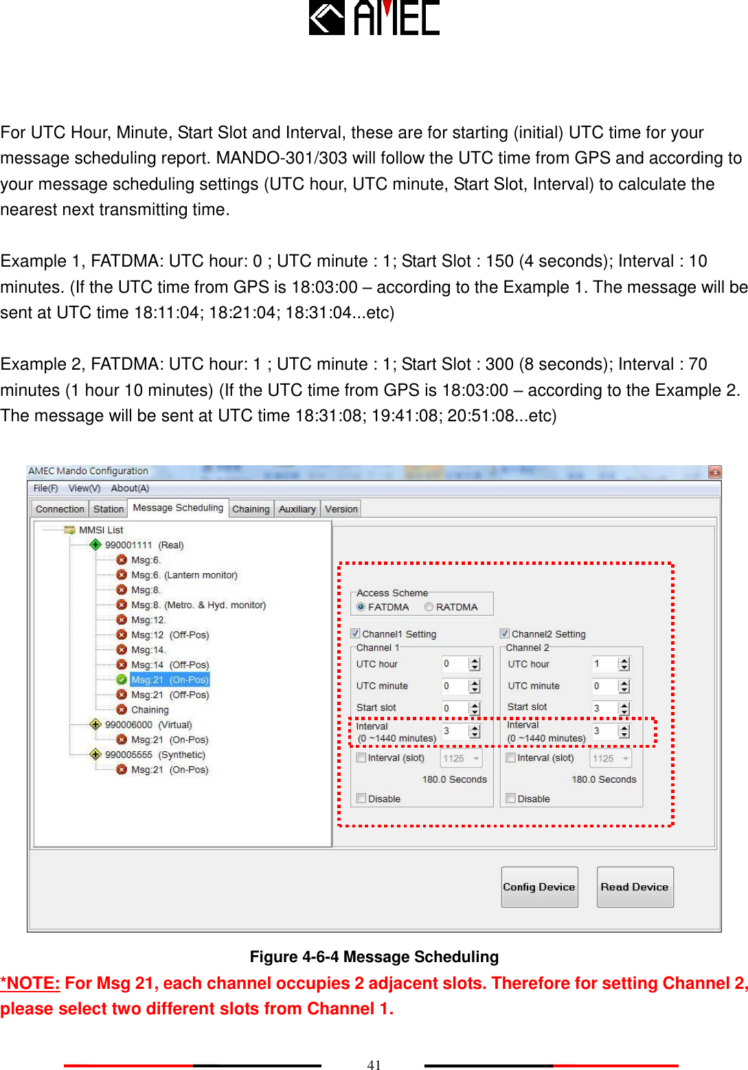
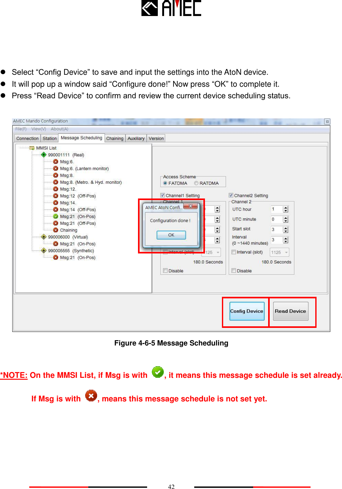
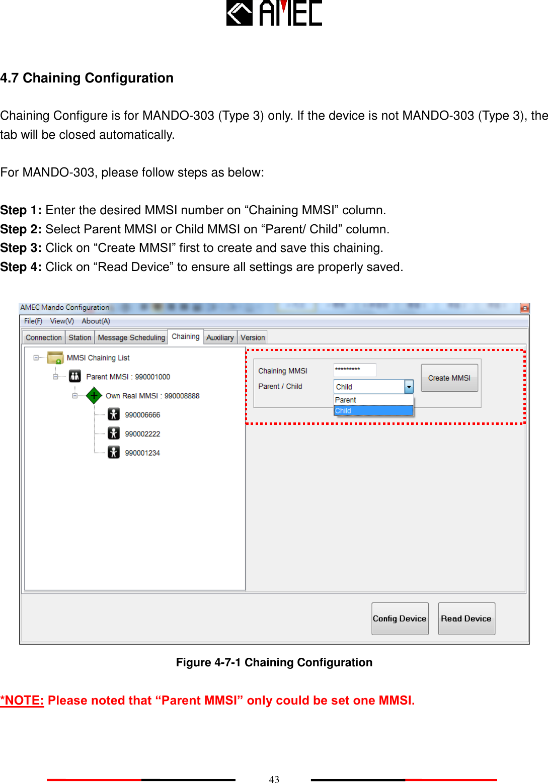
Tideland Signal 0701013 Wireless aid to navigation providing radar beacon and AIS functionality User Manual TABLE OF CONTENTS

Tideland Signal Corporation Wireless aid to navigation providing radar beacon and AIS functionality TABLE OF CONTENTS

User Manual

   I  COPYRIGHT The entire contents of this manual, including any future updates, revisions, and modifications to specifications, shall remain the property of Alltek Marine Electronics Corp. (hereinafter AMEC) at all times. Unauthorized copies or reproductions of this manual, either in part or as a whole, are strictly prohibited. The contents herein can only be used for the purpose subjects to this manual.  DISCLAIMER AMEC is devoted in publishing and maintaining this manual. As we continue to improve our Aids to Navigation  Automatic  Identification  System  (AIS  AtoN)  products,  information  in  this  manual  is subjected  to  changes  without  notice.  AMEC  does  not  make  any  representations  or  warranties (implied or otherwise) regarding the accuracy and completeness of this manual and shall in no event be liable for any loss of profit or any commercial damage, including but not limited to special, incidental, consequential, or other damages.  CONTACT US AT:  Technical Support:                                          Sales & Marketing: ALLTEK MARINE ELECTRONICS CO., LTD 7F, NO. 605, Ruei-Guang RD., Neihu, Taipei, Taiwan 114 TEL: +886 2 2627 1599 FAX: +886 2 2627 1600 www.alltekmarine.com (Your Local Dealer/Agent Warranty Stamp) Version 1.42
   II  Please carefully read this manual before start using the AIS AtoN device. This product is an auxiliary monitoring device, and it should not be relied upon as the sole monitoring navigation system. Failure to operate this system in accordance with the operating instructions specified in this manual  may  result in  unreliable or  reduced system performance. Improper operation  or installation may cause damage to the equipment or injury to personnel. AMEC shall in no event be liable for any loss of profit, personal injury, unpredictable damage arising out of incorrect operation or installation or any kind of product misuse or abuse.                        WARNING! SAFETY INSTRUCTIONS ELECTRICAL SHOCK HAZARD.        Do not open the case of the          equipment. Only qualified   personnel should work inside the equipment. WARNING TURN OFF THE POWER IMMEDIATELY IF WATER LEAKS INTO THE EQUIPMENT OR OBJECT DROPS INTO THE EQUIPMENT.        Continue operating the equipment could cause electrical shock or fire. Contact your nearest distributor for service. DO NOT DISASSEMBLE OR MODIFY THE EQUIPMENT. Improper disassemble or modification could cause electrical shocks, fire, or personal injury. WARNING DO NOT PLACE ANY LIQUID-FILLED CONTAINER ON TOP OF THE EQUIPMENT.   Improper disassemble or modification could cause electrical shocks, fire, or personal injury. TURN OFF THE POWER IMMEDIATELY IF THE EQUIPMENT IS EMMITTING SMOKE OR FIRE.        Continue operating the equipment could cause electrical shock or fire. Contact your nearest distributor for service. EVEN THOUGH THE EQUIPMENT IS WATERPROOF, PLEASE AVOID DIRECT CONTACT WITH RAIN FALLING OR WATER SPLASH. Electrical shock or fire could be resulted if water leaks into the equipment. AVOID OPERATING THE EQUIPMENT WITH WET HANDS. Electrical shocks could be resulted if operating with wet hands. PLEASE USE THE PROPER FUSE. Damage to the equipment or fire could be resulted if using the wrong fuse.
   III  Table of Contents  I.    COPY RIGHT & DISCLAIMER   II.    WARNING & SAFETY INSTRUCTION III.    FORWARD    Pages 1    INTRODUCTION ................................................................................................ 1 1.1 MANDO-301/303 Overview .................................................................................................. 1 1.2 MANDO-301/303 Features ................................................................................................... 4 1.3 Type of AIS ........................................................................................................................... 5 1.4 AIS AtoN Message ............................................................................................................... 6 1.5 About This Manual .............................................................................................................. 7 2    INSTALLATION.................................................................................................. 8 2.1 General ................................................................................................................................. 8 2.1.1 Safety Instructions ........................................................................................................ 8 2.1.2 Items in the Package .................................................................................................... 9 2.2 Installation Procedure ......................................................................................................... 9 2.3. MANDO-301/303 External Connections .......................................................................... 12 2.4. Installing VHF Antenna .................................................................................................... 13 2.5. Installing GPS Antenna .................................................................................................... 15 3    WIRING DIAGRAM/PIN DEFINITION .............................................................. 17 4    MANDO-301/303 CONFIGURATION ............................................................... 20 4.1 Configuration Start-up ...................................................................................................... 20 4.2 Serial Port Searching ........................................................................................................ 21 4.2.1 Serial Port Setting ....................................................................................................... 21 4.2.2 VDL Setting .................................................................................................................. 25 4.3 AtoN MMSI Setup ............................................................................................................... 26 4.4 Delete Selected MMSI ........................................................................................................ 28 4.5 AtoN Station Data Setting ................................................................................................. 29 4.5.1 Name and Type of AtoN Device ................................................................................. 30 4.5.2 Position Information ................................................................................................... 31 4.5.3 Transmit Setting .......................................................................................................... 32 4.5.4 Off Position ................................................................................................................. 34 4.5.5 Dimensions ................................................................................................................. 35
   IV 4.5.6 All Settings Complete ................................................................................................. 36 4.6 Message Scheduling ......................................................................................................... 36 4.7 Chaining Configuration ..................................................................................................... 43 4.8 Delete Selected Child/Parent MMSI.................................................................................. 45 4.9 Auxiliary ............................................................................................................................. 46 4.10 Version ............................................................................................................................. 47 5    APPENDIX ....................................................................................................... 48 5.1 Product Specifications ...................................................................................................... 48 5.2 Dimensions ........................................................................................................................ 51 5.3 Accessories ....................................................................................................................... 54 5.4 Built-in Integrity Test (BIIT) ............................................................................................... 57 5.4.1 BIIT Function for Antenna Disconnect ...................................................................... 57 5.4.2 BIIT Function for Receiver Channel 1 and/or Channel 2 Failure ............................. 57 5.5 Troubleshooting ................................................................................................................ 57 5.6 Type of AtoN ...................................................................................................................... 58 6    WORLDWIDE WARRANTY ............................................................................. 59 7    DECLARATION OF CONFORMITY ................................................................. 62 8    ACRONYMS .................................................................................................... 63
   1 1    INTRODUCTION 1.1 MANDO-301/303 Overview Aids to Navigation (AtoN) AIS is one of the latest applications of AIS technology. The AIS AtoN transponder can be installed in lighthouse, lantern, buoy, other fixed and floating aids, or offshore platforms to transmit warning, navigational, and meteorological data to approaching vessels and/or to shore stations. AMEC offers two types of AIS AtoN: MANDO-301 (Type 1) and MANDO-303 (Type 3).   Type 1 (MANDO- 301) – It transmits on FATDMA slots given in its configuration and has no receiver. The FATDMA slots must be pre-configured by base station.     Figure 1-1-1 AIS AtoN Type 1 Block Diagram VHF Antenna GPS Antenna
   2        Type 3 (MANDO-303) – It has AIS receive and transmit capabilities in accordance with Recommendation ITU-R M.1371. Using FATDMA/RATDMA.   Figure 1-1-2 AIS AtoN Type 3 Block Diagram  A pre-programmed transmitting schedule can be configured to broadcast AtoN messages through FATDMA  or  RATDMA.  The  MANDO-301/303  AtoN  transponder  is  designed  to  broadcast  the following messages:   Current position;     AtoN status;   Control information;     Support Synthetic, Virtual and Chaining functions;   Meteorological / hydrological information   VHF Antenna GPS Antenna
   3   In  normal  conditions,  the  unit  transmits  a  report  with  AIS  AtoN  position  in  an  ITU-R  M.1371 message 21. In addition, the AIS AtoN broadcasts AIS Message 6, which enables the operator to monitor the AtoN device for solar/battery voltage, flash setting and light status. Subject to the fitting of appropriate measuring devices, meteorological/hydrological data and other parameters can be obtained via Message 8.  A brief  summary  of  all the messages  processed  by the  AIS AtoN  are defined in section 1.4.  MANDO-301/303 AIS AtoN are fully IALA and IEC compliant devices, and provide users choices from basic PCB modules to rugged aluminum enclosed unit. The compact PCB module (102mm x 105mm x 49mm) is giving a great flexibility for users to integrate AIS AtoN transceiver into their floating lantern or buoy. The weatherproof anodized aluminum housing (140mm x 155mm x 60mm) offers user the variety of mounting methods.  Moreover, AMEC’s MANDO series is one of the most power-saving AtoN transceivers with the low power consumption while offshore power resources are limited.  MANDO-303  is  also  equipped  with  multiple  digital/analog  interfaces,  which  provides  user  the flexibility to connect other communication devices, hydraulic, and metrological sensors.
   4 1.2 MANDO-301/303 Features   Low power consumption   Operation condition: 12V DC, reporting interval 3 minutes. -  MANDO-301: FATDMA: < 0.288 Ah/day   -  MANDO-303: FATDMA: < 0.432 Ah/day   RATDMA: < 1.656 Ah/day     Multiple interfaces:     -  Analog input x 4 -  Digital output x 1 -  Digital input x 1   - RS-232 x 2 -  1 pps from internal GPS output   Support remote configuration (for MANDO-303 only)       Support meteorological & hydrological data     Customer design flexibility upon request
   5 1.3 Type of AIS The marine Automatic Identification System (AIS) is a location  and vessel information reporting system. Some elements of AIS networks are illustrated in the following table:  Table 1-3 Type of AIS elements Class A AIS Transponder ‧ Transmits and receives AIS signal. ‧ Intended for vessels meeting the requirements of IMO AIS carriage requirement.   ‧ It is mandatory for all commercial vessels that exceed 300 tons to be equipped with Class A AIS. Class B AIS Transponder ‧ Transmits and receives AIS signal. ‧ Not necessarily in full accord with IMO AIS carriage requirements. ‧ It is not mandatory for vessels to be equipped with Class B AIS. ‧ Suitable for recreational vessel, in enhancing its safety at sea.     AIS Receiver ‧ Only receives AIS signal.   ‧ Does not have transmitter to send out AIS signal. ‧ Suitable for recreational vessel that does not want to send out its vessel information. AIS AtoN ‧ AIS Aids to Navigation Station ‧ Transmits AIS AtoN signal. ‧ Receives .AIS AtoN signal. (Type 2 and Type 3 only) ‧ Capable of supporting synthetic and virtual AtoN. ‧ Can be installed in lighthouses, lanterns, buoys. ‧ Support lantern monitoring. ‧ Support meteorological and hydrological messages.
   6 1.4 AIS AtoN Message Table 1-4 Summary of AIS AtoN Messages supported by Mando Series Message ID Message Type Slot Length Description 6 Addressed Binary Message 1 to 5 (varies) Binary payload that contains the MMSI, usually of a base station, which is designated to receive the message that is sent until it is acknowledged; May contain information about the AtoN equipment, such as meteorological and hydrological information that is obtained from a daughterboard or external sensors. 8 Broadcast Binary Message 1 to 5 (varies) Binary payload that broadcasts to any equipment that can receive it; May contain information about the AtoN equipment, such as meteorological and hydrological information that is obtained from a daughterboard or sensors. 12 Addressed Safety Related Message 1 to 5 (varies) Safety-related text that is addressed to a specific MMSI, usually a base station; Message is sent until it is acknowledged; Warns of an AtoN malfunction. 14 Broadcast Safety Related Message 1 to 5 (varies) Safety-related text for broadcast communication that is received by all units that can receive the message; Warns of an AtoN malfunction. 21 Aids to Navigation Report 2 slots AtoN position report that is usually transmitted every 3 minutes and is meant to be seen by all AIS transponders; Contains information about the AtoN, such as the origination MMSI, name of the AtoN (if applicable), and the type of AtoN (fixed or floating); Sends the Aids to Navigation Report and a warning to approaching vessels. 25 AtoN Position Report 1 to 5 (varies) Intended for short, infrequent data transmissions and is designed to save bandwidth; Used for chaining.
   7 1.5 About This Manual The manual contains installation instructions and operating information for MANDO-301/303. While most of the installation can be performed by the user, a final commissioning can be done by your local agent/dealer where needed or required. AMEC and the local agent/dealer will not bear any responsibilities over any damages resulted in improper installation by unauthorized agent/dealer.
   8 WARNING Warning     注意 2    INSTALLATION 2.1 General 2.1.1 Safety Instructions Before proceeding with installation, please take note of the following safety instructions and read through this installation manual carefully.                           SAFETY INSTRUCTION SAFETY INSTRUCTIONS    ELECTRICAL SHOCK HAZARD       Do not open the case of   the equipment. Only qualified personnel should work inside the equipment. WARNING TURN OFF THE POWER BEFORE PROCEEDING WITH INSTALLATION.        Proceeding with installation with the power on could cause electrical shock or fire.   AVOID INSTALLING THE EQUIPMENT WHERE THERE IS DIRECT CONTACT WITH RAIN FALLING OR WATHER SPLASH. Electrical shock or fire could be resulted if water leaks into the equipment. PLEASE FOLLOW THIS INSTRUCTION MANUL TO PROCEED WITH THE INSTALLATION. AMEC and your local agent/dealer will not bare any responsibility of equipment damage or personnel injury due to improper installation. Warning Label A warning label (Figure 2-1-1) is attached underneath the equipment. Warranty of the equipment will be invalid if this label is detached or broken. AMEC and your local agent/dealer will not bare any responsibility of any damage to the equipment, or damage in related to the equipment, personnel injury, and etc. Reject the equipment if this label is detached or broken. Please contact your local agent/dealer if this label is missing. MAKE SURE THE POWER SOURCE AND THE POWER INPUT OF THE EQUIPMENT ARE COMPATIBLE. Damage to the equipment and fire could be resulted if the power sources are not correct. Please check the correct power input on the adaptor. Figure 2-1-1 Warning label Name: Warning Label No Warranty if this label is detached or broken. 保固撕毁无效
   9  2.1.2 Items in the Package  Table 2-1-2 Items in the Package No. Description Qty 1 MANDO-301/303 AIS AtoN main unit 1 2 Installation Kit Power cable 1.5M, AWG 16   1 8 pin connector with waterproof cup, cable 1M, AWG 24 1 12 pin connector with waterproof cup, cable 1M, AWG 26 1 M4×6 Screw 8 1/4×3/4 Screw 4 3 CD-ROM: AMEC AtoN Configuration and Operation Manual 1   2.2 Installation Procedure Please complete the AtoN installation by the following steps:   Unpacking Unpack the standard package and verify all components.    Initial Inspection Inspect all hardware for damage. If there is any damage, please consult directly with AMEC or authorized local distributor/dealer. Retain original packing material for possible future use in shipping the AIS Monitoring System.    Installing the AtoN device Please survey a suitable place for device installation. Firmly screw the four M4×6 screws from the standard package to the hole.
   10  Installation: Horizon Type A.  Fix the mounting plat B.  Use the self drilling screw C.  Finish the installation the Device                                   Figure2-2-1 Installation: Horizon Type                             Figure2-2-2 Installation: Horizon Type
   11 Installation: Vertical Type D.  Fix the mounting plat E.  Use the self drilling screw F.  Finish the installation the Device                        Figure2-2-3 Installation: Vertical Type                                   Figure2-2-4 Installation: Vertical Type
   12 GPS Antenna VHF Antenna Battery / Solar Power Hydrological / Weather R PC / NB 2.3. MANDO-301/303 External Connections                            *NOTE:  CON1 and CON2 can be alternately used.
   13 2.4. Installing VHF Antenna Installation of a VHF antenna is as important as the transceiver for reliable communications. Please check the following picture and caution for your installation references.                           Figure2-3 Installing VHF Antenna  When installing VHF antenna, please follow all of the manufacturer's instructions with particular attention  to  the  cable  routing  and  connection.  (For  better  product  performance,  AMEC  VHF antenna is highly recommended.)    Ensure the cable connector is carefully secured.   Place the antenna as high as practical on the buoy and separate as much as possible.   Ensure the antenna is installed vertically with a minimum of 2 meters of clearance from all conductive material.   Ensure the antenna has a 360° line of sight to the horizon.   VHF Connector M Jack/PL-259 POWER 5D-FB cable
   14      Avoid the antenna be surrounded by any obstacle or metal object due to signal interference.   Do not stabilize the VHF antenna with metal holder.   The bottom of the VHF antenna is the signal receiving blind spot.     Keep the antenna cable as short as possible.   The antenna cable diameter should be 5D/8D or even better ones.   Avoid bare wire winding & insulating tape wrapping when connecting with extended antenna cable.    Installation Process 1)  Place the VHF antenna mounting bracket on a rigid surface and install the antenna. 2)  Install the coaxial cable from the antenna to the AtoN location. 3) Connect the cable to the AtoN device.  Surge absolver Lightning arrestors should be used in all antenna cables if there is a risk of lightning strike.
   15 2.5. Installing GPS Antenna Since the punctuality of internal transmission of the AtoN device relies on the accuracy of the time signal obtained from the GPS system, the correct installation of GPS antenna is essential. When installing GPS antenna, please follow all of the manufacturer's instructions with particular attention to the cable routing and connection. (For better product performance, AMEC GPS antenna is highly recommended.)                     Figure 2-4 Installing GPS Antenna   Connector TNC female POWER    GPS RG-58 cable
   16  When installing the GPS antenna, follow the cautions below.   Ensure the cable connector is carefully secured.   Position  the  antenna  as  high  as  possible  to  prevent  ice  or  spray from  negatively  affecting signal reception.   Be sure no obstructions are between the GPS antenna and the sky.   Place the GPS antenna at least 3m from the VHF antenna due to signal interference.  Installation Process 1)  Place the GPS antenna mounting bracket on a rigid surface and install the antenna. 2)  To reduce signal interference, use only high quality coaxial cable and keep the cable length as short as possible. 3)  Install the coaxial cable from the antenna to the AtoN device location. 4)  Connect the cable to the AtoN device.  Surge absolver Lightning arrestors should be used in all antenna cables if there is a risk of lightning strike.
   17 3    WIRING DIAGRAM/PIN DEFINITION   Power Connector   Figure 3-1 Pin Assignments Front View   Pin number Pin definition Description Color 1 PWR Positive (+),   the input should be 12V DC Red 2 N/A N/A N/A 3 GND Power ground Black 1 3 2
   18    Con1: (ADC & RS-232 )   Figure 3-1 Pin Assignments Front View      (Part No.: LTWBU-12BFFM-LL7A01 by Amphenol LTW) * 1pps will be sent out when the GPS is power on and in 3D fix.   *NOTE:    Analog to digital input (Pin 5~8) are used to measure voltage between 0V~36V range. Pin number Pin definition Description Color 1 RS232 TX Communication interface Brown 2 GND Signal ground (RS-232) Blue 3 1 pps 1 pps (1 pulse per second from GPS) * White 4 GND Ground(GPS) Green 5 ADC4 Analog to Digital input 4   Yellow 6 ADC3 Analog to Digital input 3 Gray 7 ADC2 Analog to Digital input 2 Pink 8 ADC1 Analog to Digital input 1 Red 9 RS232 RX Communication interface Black 10 GND Ground Orange 11 NC Not connect Purple 12 NC Not connect Light Green
   19    Con2: (Control, Monitor & RS-232)   Figure 3-2 Pin Assignments Front View  (Part No.: LTWBD-08BFFM-LL7A01 by Amphenol LTW) Pin number Pin definition Description Color 1 RS232_RX Configuration interface Black 2 RS232_TX Configuration interface Brown 3 GND Signal ground (RS-232) White 4 ALM_C ALARM C Blue 5 ALM_B ALARM B Red 6 ALM_A ALARM A Orange 7 CTL_IF Digital in signal Yellow 8 V_CTL Digital in power Green *NOTE :   1. RS-232 Tx & Rx should be reversed when connecting to PC. (TxRx; Rx Tx) 2.  Software will change depend on customer’s application. 3.  Digital in (Pin 7&8) is used to inform MANDO for event was happened. Only need connect V_CTL to the voltage (0V~36V), and connect the CTL_IF to GND. 4.  Under normal operation, ALM_A will be connected to ALM_B. When MANDO works improperly or out of power, ALM_A is connect to ALM_C to notice user.
   20 4    MANDO-301/303 CONFIGURATION 4.1 Configuration Start-up Step 1: Connect the AtoN device with PC/Laptop via RS-232 serial port. Prepare a RS-232/USB converter when RS-232 serial port is not supported by your PC/Laptop.  Step 2: Connect the AtoN device with 12V DC (10A) power source. It is highly recommended to use a power adapter stabilizing the power source.  Step 3: Power on the AtoN device.  Step 4:Turn on PC and load AMEC Configuration Program CD. And make sure it has been properly installed on your PC/Laptop. Step 5: Double click  and start AMEC Configuration Program.  *NOTE:  All  message  assignments  and  intervals  must  be  defined  and  approved  by  the appropriate competent  authority,  such  as the  local port  authority where  the  AtoN device is installed.
   21 4.2 Serial Port Searching   Windows VISTA version Click  on  “Start”   Select  “My  Computer”   Mouse  right  click  “Properties”   Select  “Device Manager”  Click Port (COM&LPT)    Windows XP version Click on  “Start”  Select “My Computer”   Click “Control  Panel”  Select “System”  Choose “Hardware”  Select “Device Manager”  Click Port (COM&LPT)  Choose the Prolific RS-232-to-Serial Com Port (Com3) as designated port numbers.     Figure 4-2 Serial Port Searching      4.2.1 Serial Port Setting
   22 Step 1: Start AMEC MANDO-301/303 Configuration Program. Step 2: Enter the corresponding Serial Port & Baud Rate information. Step 3: Click “Connect” to complete and save the setting.   Figure 4-2-1-1 Serial Port Setting  *NOTE: Only “Serial Port” and “Baud Rate” need to be set, other parameters are default. AMEC MANDO-301/303 default Baud Rate is 115,200-bps.           If you key-in wrong Serial Port, you could not enter in and PC/Laptop will jump up a window to
   23 remind you to re-check Serial Port.     Figure 4-2-1-2 Error Serial Port
   24    If you do not connect Power or other problem, PC/Laptop will jump up a window to remind you to re-check all connection.         Figure 4-2-1-3 Connections failed
   25  4.2.2 VDL Setting  If your device is MANDO-303 (Type 3), you could remote other MANDO-303(Type 3) via VDL.   Step 1: After setting Serial Port and connecting with PC/Laptop, please choose “VDL”. Step 2: Enter desired MMSI which you would like to remote control. Step 3: Click “Connect” to complete and save the setting.    Figure 4-2-2 VDL Setting  *NOTE: After setting the “VDL”, you can continue setting the following tabs.
   26 4.3 AtoN MMSI Setup Step 1: Enter the valid MMSI number under “MMSI” column. Step 2: Select “Real AtoN” under the “Real / Virtual” column. Step 3: Click “Create” to save and create the new MMSI. Step 4: Press “Read Device” to confirm and review the MMSI setting.    Figure 4-3-1 AtoN MMSI Setup  *NOTE 1: The MMSI number is controlled by a competent authority and must be a legitimate number. *NOTE 2: The default MMSI number is 000000000. A MMSI number for Real AtoN must be setup first before creating other MMSI for Virtual or Synthetic AtoN .
   27    Please follow all steps above to create Virtual MMSI or Synthetic MMSI. Check if there are all correct MMSI data saved in the “MMSI” column.     Figure 4-3-2 AtoN MMSI Setup
   28 4.4 Delete Selected MMSI   Select the desired MMSI to be deleted under the “MMSI” column.   Right-click and it will jump up window written “Delete”.    Click “Delete” to erase all setting of this MMSI number.   Figure 4-4 Delete Selected MMSI
   29 4.5 AtoN Station Data Setting Step 1: After the MMSI (Real/Virtual/Synthetic) is successfully setup, user can continue with        rest of AtoN station data setting. Step 2: After all AtoN device data setting, please click “Config Device” button to save the data when         all settings are completed. PC/Laptop will pop-up window said “Configuration done!”. Then press “OK” to complete the setting. Step 3: Click “Read Device” to check and make sure all AtoN settings are correct.   Figure 4-5 AtoN Station Data Setting
   30  4.5.1 Name and Type of AtoN Device  Step 1: Enter the name of AtoN device. Step 2: Select the correct type for the AtoN device.     Figure 4-5-1 Name and Type of AtoN Device Setting
   31  4.5.2 Position Information  Step 1: Select the type of EPFS and position accuracy information. Step 2: Enter the Latitude and Longitude of the AtoN position. Step 3: Choose 8-bit data for AtoN Status. (“V” means 1; Empty means 0.) 1.  Bit 7, 6, 5 mean Page ID. For example: Page 7 (binary 111); 2.  Bit 4, 3 mean RACON status; 3.  Bit 2, 1 mean Light Status; 4.  Bit 0 means status. Ex: 0= good health; 1=alarm     Figure 4-5-2 Position Information
   32  4.5.3 Transmit Setting  Step 1: Choose the desired output power of 2W, 5W, or 12.5W.   Figure 4-5-3-1 Transmit Setting  *NOTE: The output power can only be setup at the Real AtoN. NOTE: If user makes configuration via the configuration port using the ACF sentence below: “ $--ACF,xxxxxxxxx,x,llll.llll,a,yyyyy.yyyy,a,x,xxxx,xxxx,xxxx,xxxx,x,xx,x,a*hh<CR><LF>”, the manufacturer “Power level code” are defined as follows:  Power level of ACF sentence (Note 5)* Tx power (Watt) 0 12.5 (default) 2 2 5 5 *Please refer to IEC 62320-2
   33    Step 2: Adjust the frequency of Channel 1 and Channel 2.   Figure 4-5-3-2 Transmit Setting  *NOTE: The Channel Setting can only be setup at the Real AtoN.
   34  4.5.4 Off Position  Step 1:  Enter the desired meter of Threshold. When the position of buoy exceeds the Threshold, MANDO will enter into the off position status.  Step 2:  Please select transmission schedule when it is off position. (If user choose “Use new reporting interval”, user has to set Msg 21“Off-Pos” on “Message Scheduling” tab.)    Figure 4-5-4 Off Position
   35  4.5.5 Dimensions  Enter the distance of relative position between the GPS antenna and buoy at the Dimension/ Ref. for position column, while the black spot in the picture represents the location of GPS antenna. (Unit: Meter)    Figure 4-5-5 Dimensions  *NOTE 1: The dimensions are NOT allowed to configure at Virtual/ Synthetic AtoN. *NOTE 2: The dimension diagram shows a vertical view which indicates the distance between the GPS antenna and periphery of the buoy. For ordinary buoys, the values of A, B, C, D should be the same.
   36  4.5.6 All Settings Complete  Step 1: Click on “Config Device” to finish and save all AtoN settings. Step 2: Select “Read Device” to review and confirm all settings.   Figure 4-5-6 All Settings Complete
   37 4.6 Message Scheduling Step 1: Choose the desired MMSI number (Real/ Virtual/ Synthetic) to be scheduled under the “MMSI List” column for further message scheduling.   Figure 4-6-1 Message Scheduling  *NOTE: Please setup the MMSI number before starting message scheduling settings.
   38    Step 2: For Real AtoN, select the Message ID to be scheduled from the following: Message 6,   6  (Lantern  Monitor),  8,  8(Metro.  &  Hyd.  monitor),  12,  14,  21(On-Pos),  21(Off-Pos) and Chaining. Please refer to Figure 4-6-2.   Figure 4-6-2 Message Scheduling
   39    Step 3: For Virtual or Synthetic AtoN, one could select only Message 21(On-Pos) to be scheduled.   Figure 4-6-3 Message Scheduling
   40    Step 4: Select the desired Access Scheme: FATDMA or RATDMA (For MANDO-303 only)  Step 5: Click the checkbox of “Channel 1 Setting” and “Channel 2 Setting” to setup the broadcast timing and period parameters (User could choose Single Channel or Dual Channels). Step 6: Use the arrow keys    to adjust each parameter to setup report rate.   Figure 4-6-4 Message Scheduling  *NOTE1: To stop broadcasting the message, please click on the “Disable” checkbox. *NOTE2: FATDMA could choose “Start Slot” parameters. RATDMA could not choose it.
   41   For UTC Hour, Minute, Start Slot and Interval, these are for starting (initial) UTC time for your message scheduling report. MANDO-301/303 will follow the UTC time from GPS and according to your message scheduling settings (UTC hour, UTC minute, Start Slot, Interval) to calculate the nearest next transmitting time.    Example 1, FATDMA: UTC hour: 0 ; UTC minute : 1; Start Slot : 150 (4 seconds); Interval : 10 minutes. (If the UTC time from GPS is 18:03:00 – according to the Example 1. The message will be sent at UTC time 18:11:04; 18:21:04; 18:31:04...etc)  Example 2, FATDMA: UTC hour: 1 ; UTC minute : 1; Start Slot : 300 (8 seconds); Interval : 70 minutes (1 hour 10 minutes) (If the UTC time from GPS is 18:03:00 – according to the Example 2. The message will be sent at UTC time 18:31:08; 19:41:08; 20:51:08...etc)   Figure 4-6-4 Message Scheduling *NOTE: For Msg 21, each channel occupies 2 adjacent slots. Therefore for setting Channel 2, please select two different slots from Channel 1.
   42     Select “Config Device” to save and input the settings into the AtoN device.   It will pop up a window said “Configure done!” Now press “OK” to complete it.  Press “Read Device” to confirm and review the current device scheduling status.   Figure 4-6-5 Message Scheduling  *NOTE: On the MMSI List, if Msg is with  , it means this message schedule is set already. If Msg is with  , means this message schedule is not set yet.
   43 4.7 Chaining Configuration Chaining Configure is for MANDO-303 (Type 3) only. If the device is not MANDO-303 (Type 3), the tab will be closed automatically.    For MANDO-303, please follow steps as below:  Step 1: Enter the desired MMSI number on “Chaining MMSI” column. Step 2: Select Parent MMSI or Child MMSI on “Parent/ Child” column. Step 3: Click on “Create MMSI” first to create and save this chaining. Step 4: Click on “Read Device” to ensure all settings are properly saved.     Figure 4-7-1 Chaining Configuration  *NOTE: Please noted that “Parent MMSI” only could be set one MMSI.
   44    After setting Chaining, please choose “Message Scheduling” tab, and select Msg “Chaining” under Real AtoN Station to set up for further transmitting report rate.   Figure 4-7-2 Chaining Configuration   *NOTE:  All steps are the same as setting “Message Scheduling” when you complete the “Chaining” Setting.
   45 4.8 Delete Selected Child/Parent MMSI Step 1: Select the desired MMSI to be deleted under the “MMSI Chaining List” column. Step 2: Right-click and press “Delete” to erase all setting of this certain MMSI number.   Figure 4-8 Delete Selected Child/Parent MMSI
   46 4.9 Auxiliary There are three different parts in this column. User could set those items one by one.    Standby Mode: Please choose desired wake up time on “Standby Mode”. Please use the                  arrow keys. Off-Pos MSG: Please write down the desired words/characters on each Message Test                 Content that is used for SRM Message while it is off position.               (There are 50 characters limited) Repeat: User could choose the desired Message – Message 6, Message 8, SART –         to repeat these three Messages for other AIS AtoN Device. (Only for MANDO-303 (Type 3)  After setting all parts, please click “Send” to complete all setting. And click “Read” to save all setting.  Figure 4-9 Auxiliary
   47 4.10 Version Please press “Read Device” to confirm and review the current device information, including Device Type, Vendor ID, Manufacturer Serial Number, Software and Hardware Version (Revision).   Figure 4-10 Version
   48 5    APPENDIX 5.1 Product Specifications APPLICABLE STANDARDS IEC 60945 Ed. 4    (2002-05) IEC 61162-1 Ed. 3  (2007-04) IEC 62320-2 Ed.1  (2008-03) IEC 61108-1 Ed. 2  (2003-07) IEC 61108-2 Ed. 1  (1998-06) ITU-R M.1371-4    (2010-04) IALA A-126 Ed 1.4  (2008-06)  POWER SUPPLY Input Voltage 12V DC nominal   (at Power Connector)   POWER CONSUMPTION @ 12V DC MANDO-301 FATDMA< 0.288 Ah/day * MANDO-303 FATDMA< 0.432 Ah/day *  RATDMA<  1.656 Ah/day * * At 12.5W, reporting interval 3 minutes  TRANSMITER PERFORMANCE TX Frequency Range   156.025 MHz ~ 162.025 MHz Frequency Accuracy ±500 Hz Channel Space 25 KHz Channel Protection 1 Sec max on air Modulation GMSK / FM Data Rate 9,600 bps TX Power Control 2 / 5 / 12.5 Watt (programmable)   Carrier Power Error ±1.5 dB (normal) Nominal Impedance   50Ω
   49      RECEIVER PERFORMANCE (Type 3 Only) Numbers of Receivers 2 RX Frequency Range 156.025MHz ~ 162.025 MHz Sensitivity   PER 20% at -107 dBm Data Rate 9,600 bps PER 20% at -107 dBm Co-Channel Rejection 10 dB at 1 KHz offset Adjacent Channel Rejection 70 dB at 25 KHz Nominal Impedance   50Ω   GPS RECEIVER     Receiving Channels 50 channels Tracking &Navigation Sensitivity ≧  -159 dBm Reacquisition Sensitivity ≧  -159 dBm Horizontal Position <  2.5 m Autonomous  <  2.0 m SBAS Receiver Type SBAS: WAAS, EGNOS.MSAS, GAGAN   ENVIRONMENTAL Product  Category IEC  60945  “Protected” Operating Temperature -20℃  ~ +55℃ Storage Temperature -30℃ ~ +70℃ Humidity 95% relative humidity at 40℃   SOFTWARE TOOL AMEC  AtoN  Configuration PC  configuration  utility,   standard  supply  in  CD
   50       INPUT / OUTPUT 1) One RS-232 port for configuration 2) One RS-232 port for communication 3) One isolated control output – N.C. relay for alarm indication (default) or other control usages 4) One isolated status input channel with 5 mA constant current sink for external device status input (e.g. read light fault, light on/off, etc.) 5) Four ADC channels for external sensors 6) VHF connector (M Type) 7) VHF connector (TNC Type) 8) More extra I/O interfaces can be supplied via optional extension I/O board  CONNECTOR 1) VHF connector (M type) 2) GPS connector (TNC type)  PHYSICAL Size in mm (w) 140 mm Size in mm (h) 155 mm Size in mm (d) 60 mm Weight ≦1.5 kg Case Material Aluminum Alloy
   51 5.2 Dimensions The basic dimensions of the AMEC AtoN device are illustrated in the following pictures:                     Figure 5-2-1 Top View of AIS AtoN
   52                        Figure 5-2-2 Interfaces of AIS AtoN                              Figure 5-2-3 Side View of AIS AtoN
   53                 Figure 5-2-4 AIS AtoN Module                         Figure 5-2-5 AIS AtoN Module
   54 GENERAL ENVIRONMENTAL  5.3 Accessories The following accessories are available from AMEC. Contact our local dealer/agent for more details.  Table 5-3 Accessories Item Description Product Code Remark 1 VHF Antenna TENTA-11 Length: 1,200 mm 2 GPS Antenna AGGRESSOR-111-C Dimension:   90.5 mm(Diameter) x 108.5 mm(H)   1. VHF Antenna TENTA-11 SPECIFICATIONS      Frequency Range 156 MHz ~ 163 MHz Gain 3 dBi Polarization Vertical VSWR 1.2 typical (1.5 max). Impedance 50Ω HPB 65.77 degree FBR 1.81 dB   Product Category IEC 60945 “Exposed” Operating Temperature   -30°C to  +75°C Relative Humidity 95% RH at 40°C, non-condensing Storage Temperature -40°C to  +85°C
   55 PHYSICAL CHARACTERISTICS GENERAL      Dimensions 36 mm (ψ) x 1,200 mm (L) Weight 860g (w/o mount) Connector M Jack/ PL-259 (female) Cable 5D-FB cable     2. GPS Antenna AGGRESSOR-111-C SPECIFICATIONS     Center Frequency 1575.42 ± 2 MHz Gain 30 dB, typical Noise Figure 1.5 dB, typical Bandwidth 2 MHz min. Axial Ratio @ Zenith 3 dB max. VSWR 1.2 typical (1.5 max) Output Impedance 50Ω
   56 PHYSICAL CHARACTERISTICS ENVIRONMENTAL       Product Category IEC 60945 “Exposed” Operating Temperature   -25°C to  +55°C Relative Humidity 40% to 95% non-condensing Storage Temperature -25°C to  +70°C     Dimensions 90.5 mm (diameter) × 108.5 mm (H) Ground Size 74 mm (diameter) Weight 150 grams (without cable) Connector TNC female Cable 10 m, RG-58 cable included
   57 5.4 Built-in Integrity Test (BIIT) With BIIT (Built-in Integrity Test), the MANDO-301/303 is constantly monitoring and testing the integrity itself.  5.4.1 BIIT Function for Antenna Disconnect There is a built-in RF output power detector, which is used to monitor the VSWR of VHF antenna port. If there is any abnormal condition (open or short) at VHF port of MANDO-301/303, MANDO-301/303 will cease transmission at next transmission phase.  5.4.2 BIIT Function for Receiver Channel 1 and/or Channel 2 Failure Receiver at MANDO has built-in receiver signal strength indication (RSSI), which is designed under pre-defined threshold to judge receiver operating status. If the RSSI level is over pre-defined threshold, MANDO-301/303 will reflect receiver failure and cease transmission during next transmission phase.  5.5 Troubleshooting Please find accordance with above procedure while setting MANDO-301/303. If there is any problem, please do not hesitate to contact us or our local agent.
   58 5.6 Type of AtoN Table 5-6 The nature and type of AtoN can be indicated with 32 different codes  Code Definition  0 Default. Type of A to N not specified  1 Reference point  2 RACON  3 Fixed structure off shore, such as oil platforms, wind farms. (Note: This code should identify an obstruction that is fitted with an AtoN AIS Station.)  ship  4 Spare, Reserved for future use. Fixed A to N 5 Light, without sectors  6 Light, with sectors  7 Leading Light Front  8 Leading Light Rear  9 Beacon, Cardinal N  10 Beacon, Cardinal E  11 Beacon, Cardinal S  12 Beacon, Cardinal W  13 Beacon, Port hand  14 Beacon, Starboard hand  15 Beacon, Preferred Channel port hand  16 Beacon, Preferred Channel starboard hand  17 Beacon, Isolated danger  18 Beacon, Safe water  19 Beacon, Special mark Floating A to N 20 Cardinal Mark N  21 Cardinal Mark E  22 Cardinal Mark S  23 Cardinal Mark W  24 Port hand Mark  25 Starboard hand Mark  26 Preferred Channel Port hand  27 Preferred Channel Starboard hand  28 Isolated danger  29 Safe water  30 Special mark  31 Light Vessel/ LANBY/ Rigs  *NOTE1:  It is based on the IALA A-126 *NOTE2:  It may be confused when it is decided whether the Aid is lighted or unlighted. Therefore competent authorities may prefer to use the regional section of the message to dedicate this.
   59 6  WORLDWIDE WARRANTY  Limited warranty Subject  to  the  terms,  conditions  and  limitations  set  forth  in  this  Worldwide  Limited  Warranty (hereinafter the “Warranty”), AMEC warrants that its products, when properly installed and used, will be free from defects in material and workmanship for a period of twelve (12) months, from the date of first purchase (the ‘Warranty Period’)  For  the  purposes  of  this  warranty,  ‘date  of  first  purchase’  means  the  date  that  the product  was purchased by the first retail customer, or by the institutional customer, or in the case of a product installed  on  a  new  vessel  or  any  other  marine  related  platform  by  a  certified  AMEC  original equipment manufacturer (a  ‘AMEC  OEM’), the date that such vessel was purchased by the first retail customer.  AMEC  will, at  its  sole option,  repair  or  replace  any  defective  products or  components returned during the Warranty Period in accordance with the terms, conditions and limitations set forth below. Such repairs or replacement will be the sole remedy of the customer under this Warranty.  Limited to Original Purchaser   This Warranty is for the sole benefit of the original purchaser of the covered product and shall not extend to any subsequent purchaser of the product.    Miscellaneous Apart  from  the  specific  warranties  provided  under  this  warranty,  all  other  express  or  implied warranties relating to the above product is hereby excluded to the fullest extent allowable under law. The warranty does not  extend to any lost profits, loss of  good  will or any indirect, incidental or consequential costs or damages or losses incurred by the purchaser as a result of any defect with the covered product.  Standard Warranty Service To qualify for standard warranty service the product must be returned to a AMEC-certified service agent (i) within the Warranty Period, and (ii) within thirty (30) days of the alleged product failure. Any products returned must be securely packaged and sent pre-paid and insured to AMEC or to a AMEC-certified  service  agent.    All  products  returned  must  be  accompanied  by  a  copy  of  the original sales receipt to be eligible for standard warranty service.
   60   Obtaining Warranty Service A  list  of  AMEC-certified  service  agents  is  available  from  AMEC  Technical  Support  at www.alltekmarine.com    Other conditions This Warranty is fully transferable provided that you furnish the original proof of purchase to the AMEC -certified service agent. This Warranty is void if the label bearing the serial number has been removed or defaced.  Limitation and Exclusions In addition to any other limitations and exclusions set forth herein, AMEC is not responsible for, and this Warranty does not cover:   Failure  due  to  abuse,  misuse,  accident,  unauthorized  alteration,  modification  or  repair, improper installation or operation (whether or not by a AMEC-certified service agent) or improper storage, shipping damage or corrosion;   Costs  associated  with  routine  system  checkouts,  alignment/calibration,  sea  trials  or commissioning;   Defects  or  damage  that  result  from  the  use  of  non-AMEC  branded  or  certified  products, accessories or other peripheral equipment, including without limitation housings, parts, or software;   Aftermarket software (i.e. all software other than the original operating software sold with the products);       Products that have been refurbished, reconditioned, or remanufactured (The foregoing does not apply to products repaired or replaced pursuant to the terms of this Warranty).   Products that have been dismantled resulting in the broken label on the Products;   costs associated with overtime or premium labor costs;   differences  in  material,  coloring  or  size  that  may  exist  between  actual  products  and  the pictures or descriptions of such products in our advertising, advertising literature or on the Internet;  TO  THE  EXTENT  PERMITTED  BY  APPLICABLE  LAW,  THE  FOREGOING  WARRANTY  IS AMEC’S SOLE WARRANTY AND IS APPLICABLE ONLY TO NEW PRODUCTS PURCHASED WORLDWIDE.  THE  PROVISIONS  OF  THIS  WARRANTY  ARE  IN  LIEU  OF  ANY  OTHER WRITTEN  WARRANTY,  WHETHER  EXPRESSED  OR  IMPLIED,  WRITTEN  OR  ORAL, INCLUDING  ANY  WARRANTY  OF  MERCHANTABILITY  OR  FITNESS  FOR  A  PARTICULAR PURPOSE.
   61  THE  LIABILITY  OF  AMEC  TO  A  CUSTOMER  UNDER  THIS  WARRANTY,  WHETHER  FOR BREACH OF CONTRACT, TORT, BREACH OF STATUTORY DUTY OR OTHERWISE SHALL IN NO  EVENT  EXCEED  AN  AMOUNT  EQUAL  TO  THE  TOTAL  PURCHAE  PRICE  OF  THE PRODUCT GIVING RISE TO SUCH LIABILITY AND IN NO EVENT SHALL AMEC BE LIABLE FOR  SPECIAL,  INCIDENTAL,  CONSEQUENTIAL  OR  INDIRECT  DAMAGES  OR  LOST  OF GOODWILL, REPUTATION, LOSS OF OPPORTUNITY OR INFORMATION, DATA, SOFTWARE OR APPLICATIONS.  SOME  JURISDICTIONS  DO  NOT  ALLOW  EXCLUSION  OR  LIMITATION  OF INCIDENTAL  OR CONSEQUENTIAL  DAMAGES  SO  THE  ABOVE  LIMITATIONS  OR  EXCLUSIONS  MAY  NOT APPLY  TO  YOU.    THIS  WARRANTY  GIVES  YOU  SPECIFICLEGAL  RIGHTS  AND  YOU  MAY ALSO HAVE OTHER RIGHTS, WHICH VARY FROM JURISDICTION TO JURISDICTION.  This Warranty supersedes and replaces all previous Warranties.  In the event that any term or provision contained in this Warranty is found to be invalid, illegal or unenforceable by a court of competent jurisdiction, then such provision shall be deemed modified to the extent necessary to make such provision enforceable by such court, taking into account the intent of the parties.    No  oral  or  written  representations  made  by  AMEC  or  any  seller,  reseller  or  distributor  of  the products, including employees and agents thereof, shall create any additional warranty obligations, increase the scope, or otherwise modify in any manner the terms of this Warranty.  All AMEC products sold or provided hereunder are merely aids to navigation. It is the responsibility of the user to exercise discretion and proper navigational skill independent of any AMEC product.
   62 7    DECLARATION OF CONFORMITY  Hereby, Alltek  Marine  Electronics  Corp.  (AMEC) declares that this PASO-350 is in compliance with the essential requirements and other relevant provisions of Directive 1999/5/EC.
   63 8  ACRONYMS  ABM AIS addressed binary and safety related Message ACK Acknowledgment Message AIS Automatic Identification System AtoN Aids to Navigation BBM AIS broadcast binary message COG Course Over Ground DGNSS Differential Global Navigation Satellite System DGPS Differential Global Positioning System DSP Digital Signal Processor ECS Electronic Chart System EPFS Electronic Position Fix System FATDMA Fixed Access Time Division Multiple Access GNSS Global Navigation Satellite System GPS Global Positioning System IEC International Electrotechnical Commission IMO International Maritime Organization MMSI Maritime Mobile Service ID NMEA National Marine Electronics Association RATDMA Random Access Time Division Multiple Access RF Radio Frequency SART Search and Rescue Transponder SOG Speed Over Ground SRM Safety Related Message TDMA Time Division Multiple Access TNC Threaded Neill-Concelman Connector TX Transmitter VDL VHP Data-link Other Vessel Message VDM AIS VHF data-link message VDO AIS VHF data-link own-vessel report VHF Very High Frequency VSD Voyage Static Data VSWR Vertical Standing Wave Ratio VTS Vessel Traffic Services

Navigation menu