Tideland Signal SBCN2SYS6A SeaBeacon 2 System 6 Racon User Manual
Tideland Signal Corporation SeaBeacon 2 System 6 Racon Users Manual
UserManual.wiki
>
Tideland Signal
>
SBCN2SYS6A User Manual
Manual
Navigation menu
Upload a User Manual
Namespaces
Wiki Guide
HTML
PDF
Info
Views
User Manual
Discussion / Help
Navigation


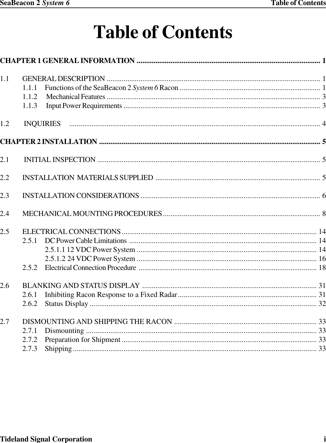
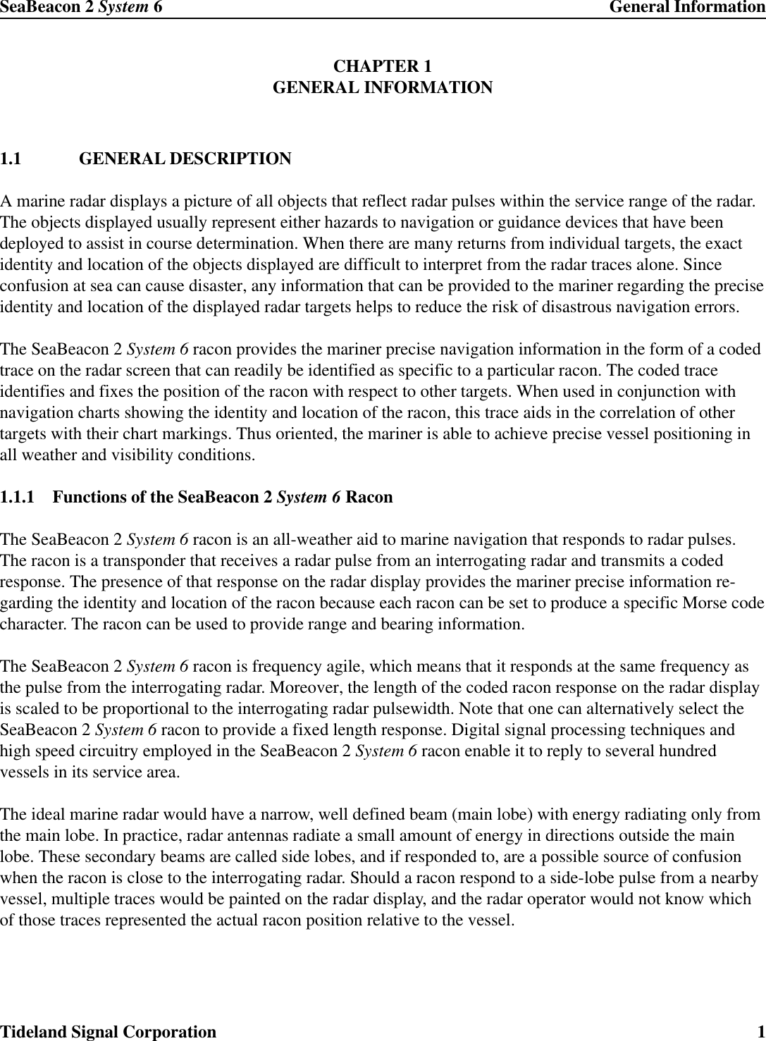
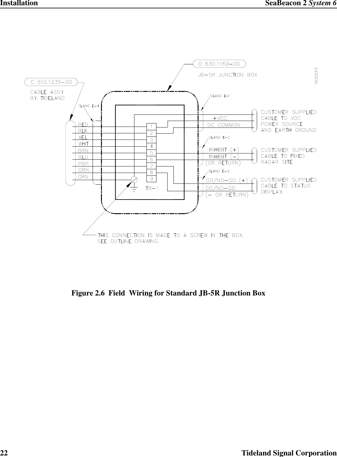
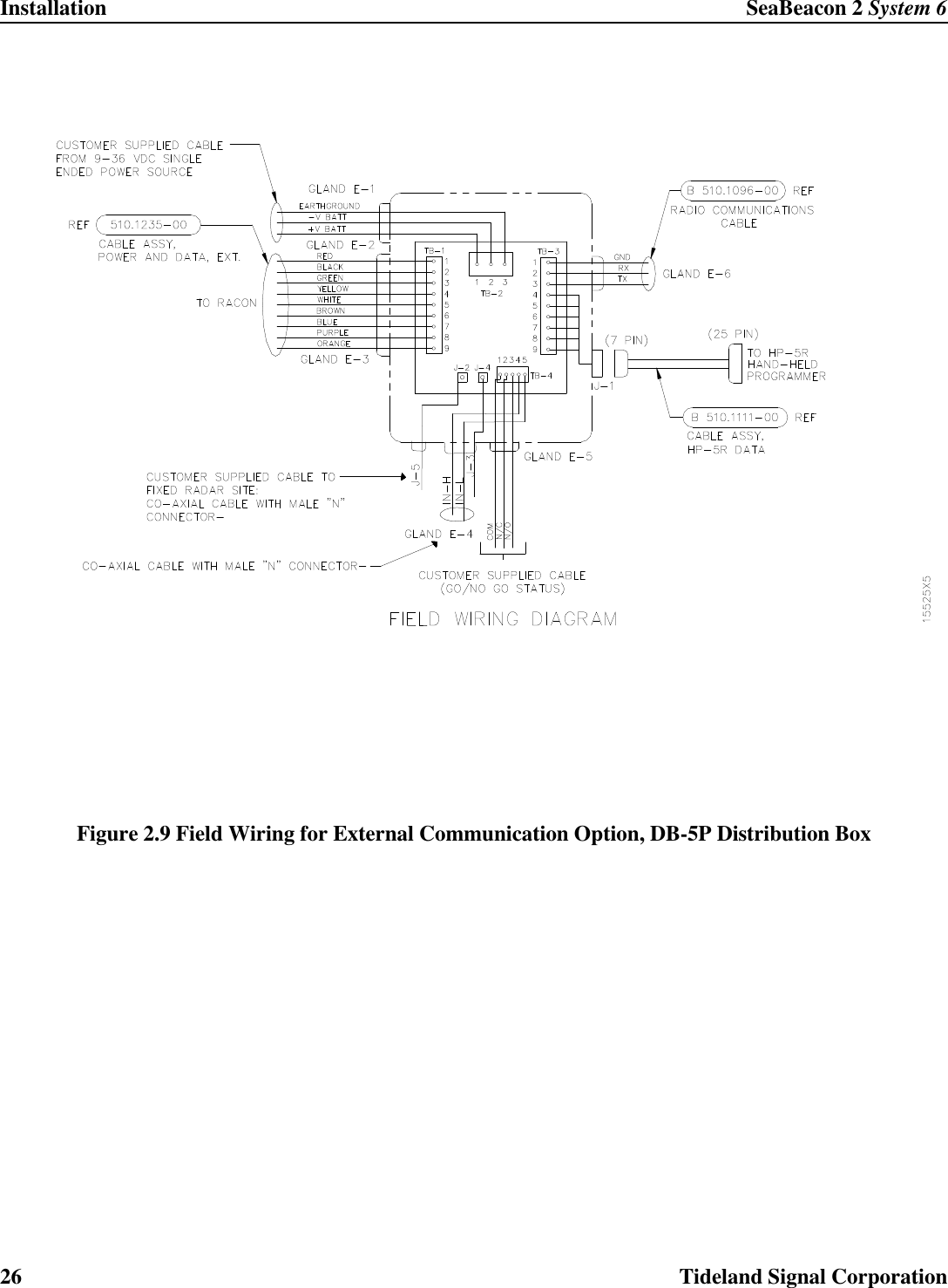
![SeaBeacon 2 System 6 InstallationTideland Signal Corporation 7Site:The racon must be leveled. For fixed mounting surfaces, install the racon within 1 degree of truevertical. For installation on buoys, just mount the racon upright.For best results, locate the racon as high as practical in order to provide a clear line-of-sight pathbetween the racon and the marine radar. In general, the higher the racon is mounted, the better is itsuseful range.For example, a ship’s radar antenna is 15 meters (50 ft) above water, and the highest point of land thevessel is approaching is 91 meters (300 ft) resulting in a nominal radar range of approximately 28nautical miles.[]TRTXNM HHR+= 08.2R is in Nautical MilesHTX and HTR are Heights in MetersFor more information about racon range estimates, please see the IALA publication “Guidelines onRacon Range Performance”, December 1999.Orientation:The racon must be mounted vertically. The orientation arrows on the lift ring and housing (oppositethe connectors) must align and should point seaward or toward the longest range of the traffic servicearea.Record of Obstruction:Create a record of the installation that notes the date of installation and any obstructions that existbetween the racon and the sea lanes where ship traffic of interest will pass. Retain this record andrefer to it periodically to determine whether any new construction is interfering with racon perfor-mance to the extent that relocation may be advisable.](https://usermanual.wiki/Tideland-Signal/SBCN2SYS6A/User-Guide-390776-Page-17.png)
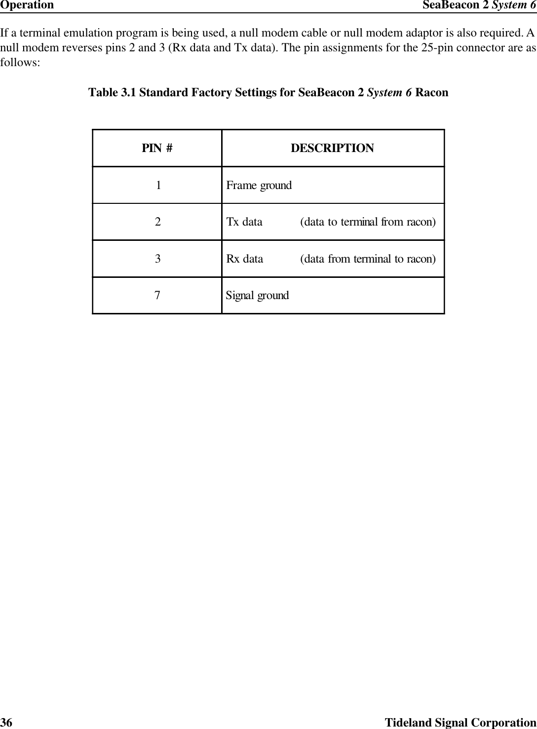
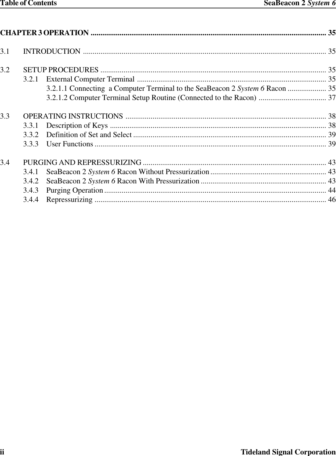
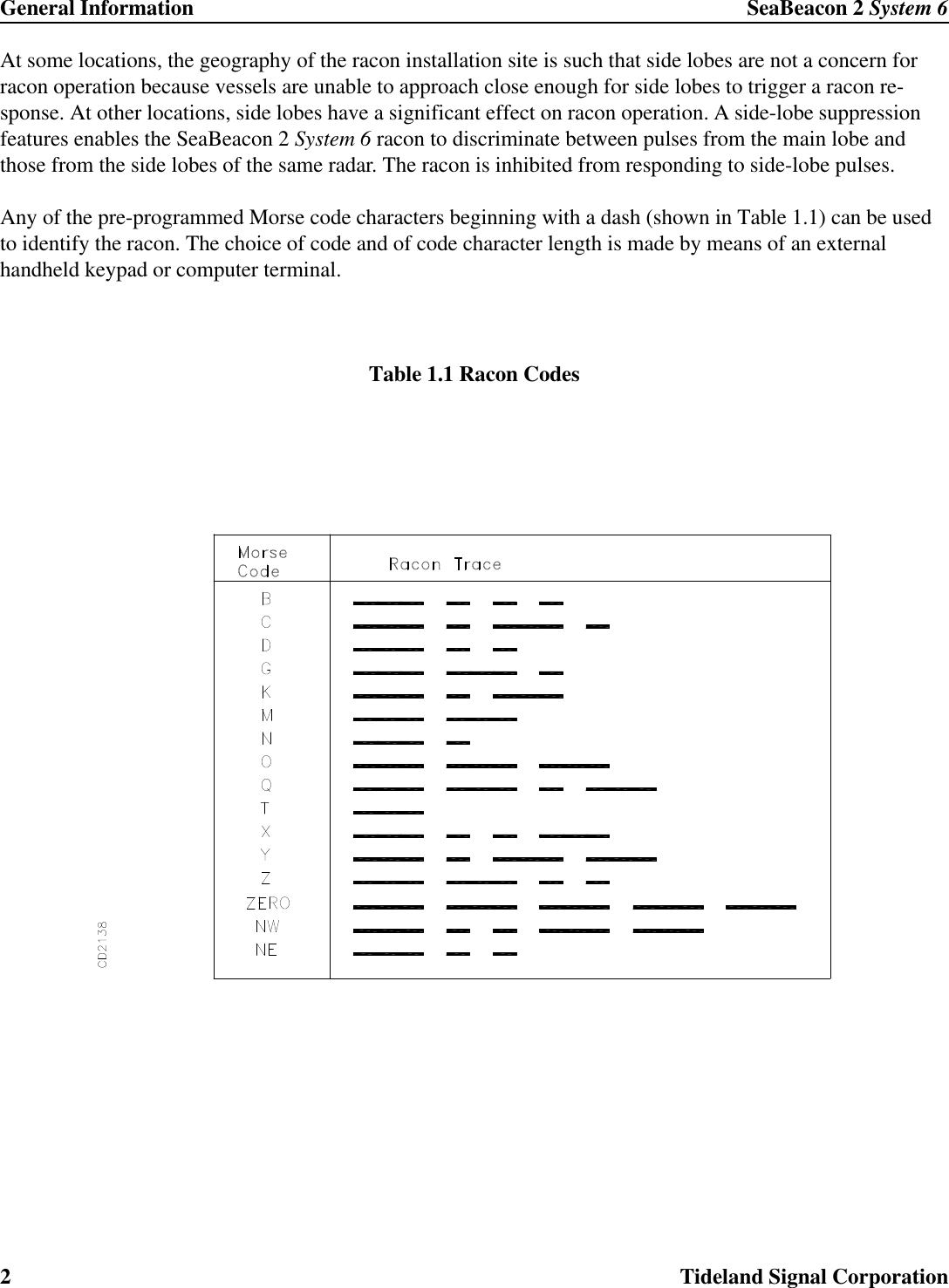
![SeaBeacon 2 System 6 OperationTideland Signal Corporation 37Communications parameters should be set as follows:3.2.1.2 Computer Terminal Setup Routine (Connected to the Racon)If using a computer terminal, turn it on or start the terminal emulation program and type the letter [O] toenable the keyboard.To communicate with the racon, press the letter [O] within 4 seconds of either the beeps or the SYSTEMOK update message. (If you do not press [O] within 4 seconds of the beep or SYSTEM OK, wait one com-plete power management cycle and then press [O] within 4 seconds of the next beep or SYSTEM OK.) Acomplete power management cycle is the duty cycle of the racon: the sum of the Active ON and the StandbyOFF times. The standard factory setting is 40 seconds.If you do not want to continue to perform another User Function, turn the keyboard off by pressing the letter[O].Baud rate: 9600Parity: NoneData bits: 8Stop bits: 1Echo: HostCR, LF: No translationHandshaking: None](https://usermanual.wiki/Tideland-Signal/SBCN2SYS6A/User-Guide-390776-Page-47.png)
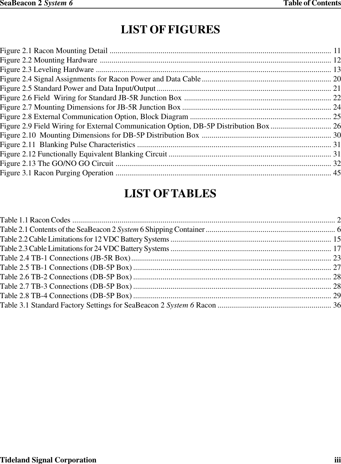
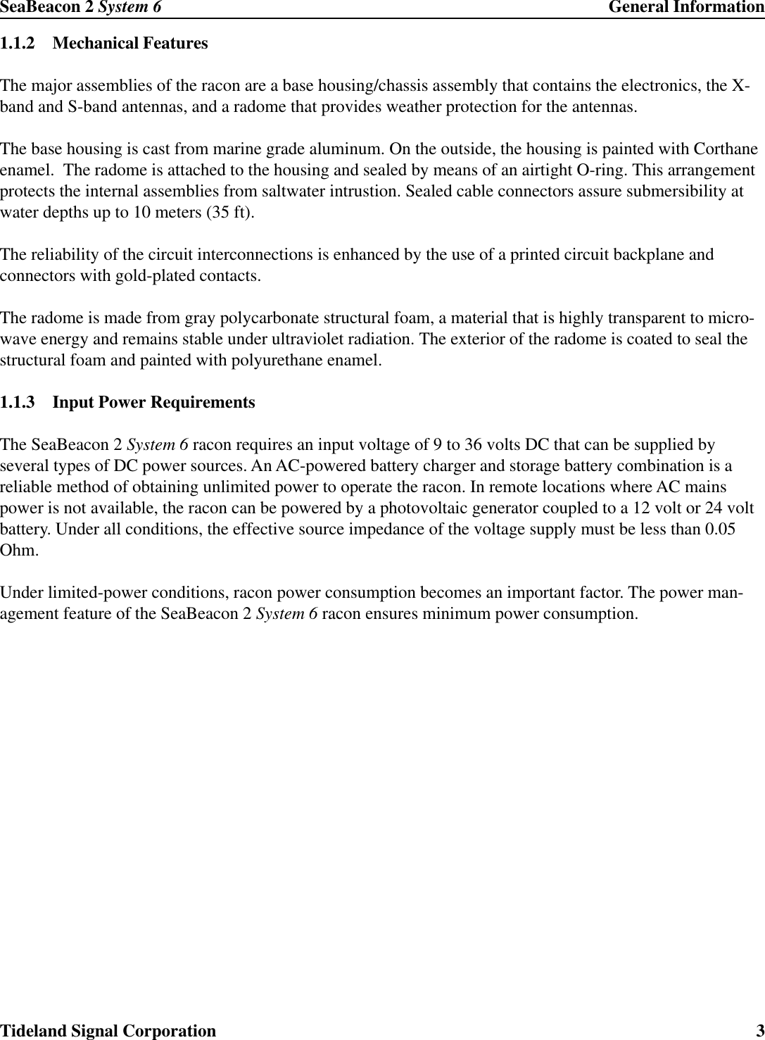
![Operation SeaBeacon 2 System 638 Tideland Signal Corporation3.3 OPERATING INSTRUCTIONS3.3.1 Description of KeysActual keys used in operating the external terminal are enclosed in brackets [ ]. Keys to be used and descrip-tions of their uses are listed below:KEYS USED FOREXTERNAL TERMINAL DESCRIPTIONLetter [O] OR [o] Turns keyboard ON or OFF; keyboard must be ON to usefunctions; when not used, the keyboard automatically reverts toOFF after a programmed timeout.[ESC] or [*] Exits a function.[<-, DEL Backspace] Deletes the last character entered on the display.[ENTER][EXE] Transfers the displayed value into the racon; starts an action.[<] or [,] Decrements the displayed value; moves between selections;[EXE] or [ENTER] must be used to transfer the value into theracon.[>] or [.] Increments the displayed value; moves between selections;[EXE] or [ENTER] must be used to transfer the value into theracon.[0] [1] [2] [3] [4] [5] [6] [7] [8][9] or [-] Enters digits into the display.[/] Restores old entry value, quits the entry, moves to next entry;this is essentially a "whoops" key or can be used to skip anentry.[;] [^] or [#] Restores old entry value, quits the entry, backs up to previousmenu entry.NOTE: When the keyboard is ON the racon will not enter Standby, its lowest power state.](https://usermanual.wiki/Tideland-Signal/SBCN2SYS6A/User-Guide-390776-Page-48.png)
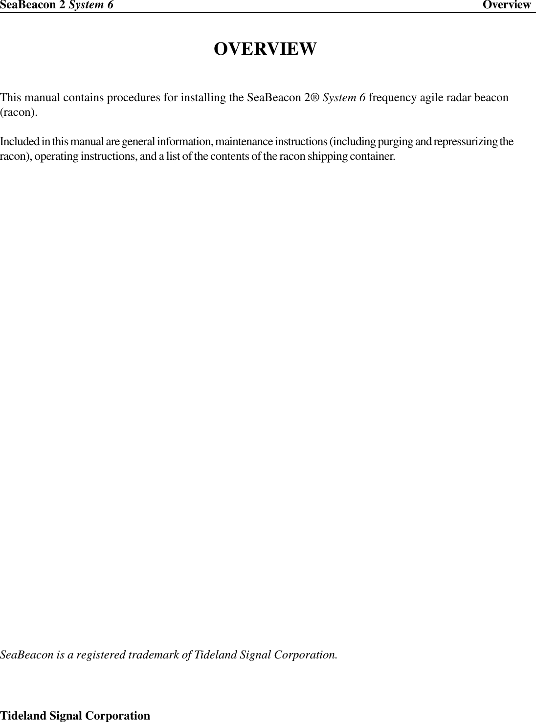
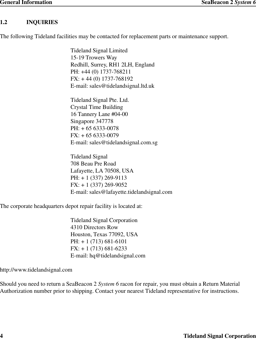
![SeaBeacon 2 System 6 OperationTideland Signal Corporation 393.3.2 Definition of Set and SelectDefinitions of Set and Select are as follows:Select:The racon presents the user with a list from which a parameter can be chosen. Items aredisplayed one at a time. The list can be viewed forwards or backwards using the [>] or [.] and[<] or [,] keys respectively.To choose an item from the list for use by the racon, press [ENTER].To skip the selection, press [/].To return to the USER FUNCTION prompt, press [ESC].Set:The racon requires the user to enter a particular value. Press the [-] key (if needed), then pressthe [0] through [9] keys as needed to form the value.If wrong digits are entered, press [ûbackspace], to delete each of the digits entered.To store the value into the racon, press [ENTER].To skip the setting, press [/].To return to the USER FUNCTION prompt, press [ESC].3.3.3 User Functions1 BAND ENABLESelect band enable for each of X and S bands.USE BAND using increment/decrement keys, select “YES” to useBank, or “NO” to disable band; X band default is “NO”;S band default is “NO”](https://usermanual.wiki/Tideland-Signal/SBCN2SYS6A/User-Guide-390776-Page-49.png)