Tideland Signal SBCN2SYS6A SeaBeacon 2 System 6 Racon User Manual
Tideland Signal Corporation SeaBeacon 2 System 6 Racon Users Manual
Manual
P.N. 011.1181-00
SeaBeacon 2 System 6 Racon
Installation Manual
Tideland Signal Corporation
Rev. 00

P.N. 011.1181-00
SeaBeacon 2 System 6 Racon
Installation Manual
Tideland Signal Corporation
P.O. Box 52430
Houston, Texas 77052
00 Released NOV 02 JCS
Rev. Description Date By

IMPORTANT NOTE
Do not discard this manual. It
contains important operating
instructions.

SeaBeacon 2 System 6 Table of Contents
Tideland Signal Corporation i
Table of Contents
CHAPTER 1 GENERAL INFORMATION .................................................................................................. 1
1.1 GENERAL DESCRIPTION .................................................................................................................. 1
1.1.1 Functions of the SeaBeacon 2 System 6 Racon ........................................................................... 1
1.1.2 Mechanical Features .................................................................................................................. 3
1.1.3 Input Power Requirements ......................................................................................................... 3
1.2 INQUIRIES ...................................................................................................................................... 4
CHAPTER 2 INSTALLATION ...................................................................................................................... 5
2.1 INITIAL INSPECTION ....................................................................................................................... 5
2.2 INSTALLATION MATERIALS SUPPLIED ........................................................................................ 5
2.3 INSTALLATION CONSIDERATIONS ................................................................................................ 6
2.4 MECHANICAL MOUNTING PROCEDURES.................................................................................... 8
2.5 ELECTRICAL CONNECTIONS........................................................................................................ 14
2.5.1 DC Power Cable Limitations .................................................................................................... 14
2.5.1.1 12 VDC Power System ................................................................................................ 14
2.5.1.2 24 VDC Power System ................................................................................................ 16
2.5.2 Electrical Connection Procedure ............................................................................................... 18
2.6 BLANKING AND STATUS DISPLAY ............................................................................................. 31
2.6.1 Inhibiting Racon Response to a Fixed Radar.......................................................................... 31
2.6.2 Status Display ......................................................................................................................... 32
2.7 DISMOUNTING AND SHIPPING THE RACON ............................................................................ 33
2.7.1 Dismounting ........................................................................................................................... 33
2.7.2 Preparation for Shipment ........................................................................................................ 33
2.7.3 Shipping.................................................................................................................................. 33

Table of Contents SeaBeacon 2 System 6
ii Tideland Signal Corporation
CHAPTER 3 OPERATION .......................................................................................................................... 35
3.1 INTRODUCTION .............................................................................................................................. 35
3.2 SETUP PROCEDURES ..................................................................................................................... 35
3.2.1 External Computer Terminal .................................................................................................. 35
3.2.1.1 Connecting a Computer Terminal to the SeaBeacon 2 System 6 Racon .................... 35
3.2.1.2 Computer Terminal Setup Routine (Connected to the Racon) ................................... 37
3.3 OPERATING INSTRUCTIONS ........................................................................................................ 38
3.3.1 Description of Keys ................................................................................................................ 38
3.3.2 Definition of Set and Select .................................................................................................... 39
3.3.3 User Functions ........................................................................................................................ 39
3.4 PURGING AND REPRESSURIZING ............................................................................................... 43
3.4.1 SeaBeacon 2 System 6 Racon Without Pressurization............................................................ 43
3.4.2 SeaBeacon 2 System 6 Racon With Pressurization ................................................................. 43
3.4.3 Purging Operation................................................................................................................... 44
3.4.4 Repressurizing ........................................................................................................................ 46

SeaBeacon 2 System 6 Table of Contents
Tideland Signal Corporation iii
LIST OF FIGURES
Figure 2.1 Racon Mounting Detail ................................................................................................................. 11
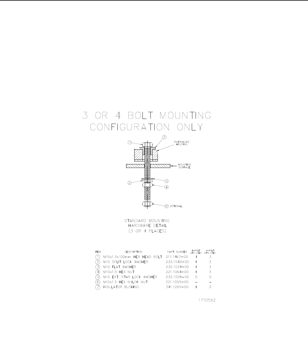
Figure 2.2 Mounting Hardware ...................................................................................................................... 12
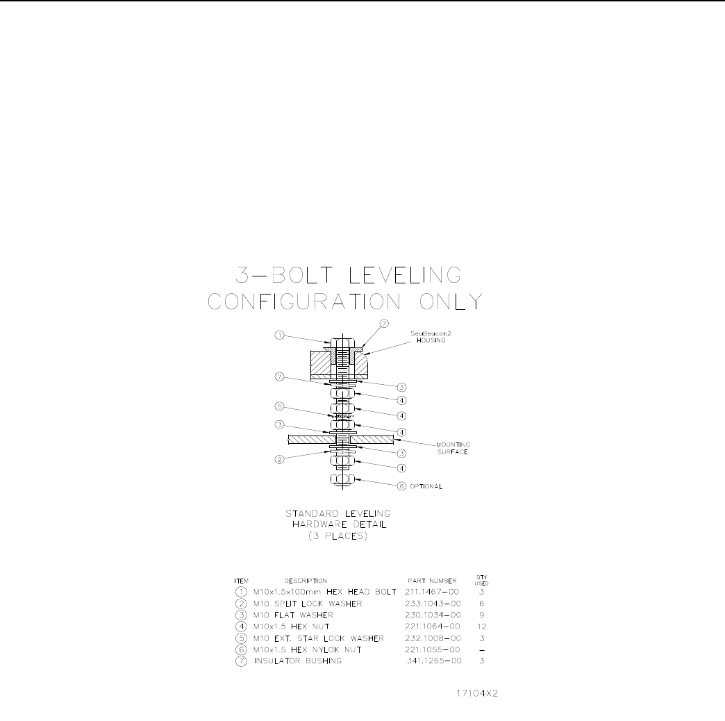
Figure 2.3 Leveling Hardware ........................................................................................................................ 13
Figure 2.4 Signal Assignments for Racon Power and Data Cable.................................................................. 20
Figure 2.5 Standard Power and Data Input/Output......................................................................................... 21
Figure 2.6 Field Wiring for Standard JB-5R Junction Box ........................................................................... 22
Figure 2.7 Mounting Dimensions for JB-5R Junction Box ............................................................................ 24
Figure 2.8 External Communication Option, Block Diagram ........................................................................ 25
Figure 2.9 Field Wiring for External Communication Option, DB-5P Distribution Box............................... 26
Figure 2.10 Mounting Dimensions for DB-5P Distribution Box .................................................................. 30
Figure 2.11 Blanking Pulse Characteristics ................................................................................................... 31
Figure 2.12 Functionally Equivalent Blanking Circuit ................................................................................... 31
Figure 2.13 The GO/NO GO Circuit .............................................................................................................. 32
Figure 3.1 Racon Purging Operation .............................................................................................................. 45
LIST OF TABLES
Table 1.1 Racon Codes ...................................................................................................................................... 2
Table 2.1 Contents of the SeaBeacon 2 System 6 Shipping Container .................................................................. 6
Table 2.2 Cable Limitations for 12 VDC Battery Systems .................................................................................. 15
Table 2.3 Cable Limitations for 24 VDC Battery Systems .................................................................................. 17
Table 2.4 TB-1 Connections (JB-5R Box)...................................................................................................... 23
Table 2.5 TB-1 Connections (DB-5P Box) ..................................................................................................... 27
Table 2.6 TB-2 Connections (DB-5P Box) ..................................................................................................... 28
Table 2.7 TB-3 Connections (DB-5P Box) ..................................................................................................... 28
Table 2.8 TB-4 Connections (DB-5P Box) ..................................................................................................... 29
Table 3.1 Standard Factory Settings for SeaBeacon 2 System 6 Racon .......................................................... 36

SeaBeacon 2 System 6 Overview
Tideland Signal Corporation
OVERVIEW
This manual contains procedures for installing the SeaBeacon 2® System 6 frequency agile radar beacon
(racon).
Included in this manual are general information, maintenance instructions (including purging and repressurizing the
racon), operating instructions, and a list of the contents of the racon shipping container.
SeaBeacon is a registered trademark of Tideland Signal Corporation.

SeaBeacon 2 System 6General Information
Tideland Signal Corporation 1
CHAPTER 1
GENERAL INFORMATION
1.1 GENERAL DESCRIPTION
A marine radar displays a picture of all objects that reflect radar pulses within the service range of the radar.
The objects displayed usually represent either hazards to navigation or guidance devices that have been
deployed to assist in course determination. When there are many returns from individual targets, the exact
identity and location of the objects displayed are difficult to interpret from the radar traces alone. Since
confusion at sea can cause disaster, any information that can be provided to the mariner regarding the precise
identity and location of the displayed radar targets helps to reduce the risk of disastrous navigation errors.
The SeaBeacon 2 System 6 racon provides the mariner precise navigation information in the form of a coded
trace on the radar screen that can readily be identified as specific to a particular racon. The coded trace
identifies and fixes the position of the racon with respect to other targets. When used in conjunction with
navigation charts showing the identity and location of the racon, this trace aids in the correlation of other
targets with their chart markings. Thus oriented, the mariner is able to achieve precise vessel positioning in
all weather and visibility conditions.
1.1.1 Functions of the SeaBeacon 2 System 6 Racon
The SeaBeacon 2 System 6 racon is an all-weather aid to marine navigation that responds to radar pulses.
The racon is a transponder that receives a radar pulse from an interrogating radar and transmits a coded
response. The presence of that response on the radar display provides the mariner precise information re-
garding the identity and location of the racon because each racon can be set to produce a specific Morse code
character. The racon can be used to provide range and bearing information.
The SeaBeacon 2 System 6 racon is frequency agile, which means that it responds at the same frequency as
the pulse from the interrogating radar. Moreover, the length of the coded racon response on the radar display
is scaled to be proportional to the interrogating radar pulsewidth. Note that one can alternatively select the
SeaBeacon 2 System 6 racon to provide a fixed length response. Digital signal processing techniques and
high speed circuitry employed in the SeaBeacon 2 System 6 racon enable it to reply to several hundred
vessels in its service area.
The ideal marine radar would have a narrow, well defined beam (main lobe) with energy radiating only from
the main lobe. In practice, radar antennas radiate a small amount of energy in directions outside the main
lobe. These secondary beams are called side lobes, and if responded to, are a possible source of confusion
when the racon is close to the interrogating radar. Should a racon respond to a side-lobe pulse from a nearby
vessel, multiple traces would be painted on the radar display, and the radar operator would not know which
of those traces represented the actual racon position relative to the vessel.
2Tideland Signal Corporation
General Information SeaBeacon 2 System 6
At some locations, the geography of the racon installation site is such that side lobes are not a concern for
racon operation because vessels are unable to approach close enough for side lobes to trigger a racon re-
sponse. At other locations, side lobes have a significant effect on racon operation. A side-lobe suppression
features enables the SeaBeacon 2 System 6 racon to discriminate between pulses from the main lobe and
those from the side lobes of the same radar. The racon is inhibited from responding to side-lobe pulses.
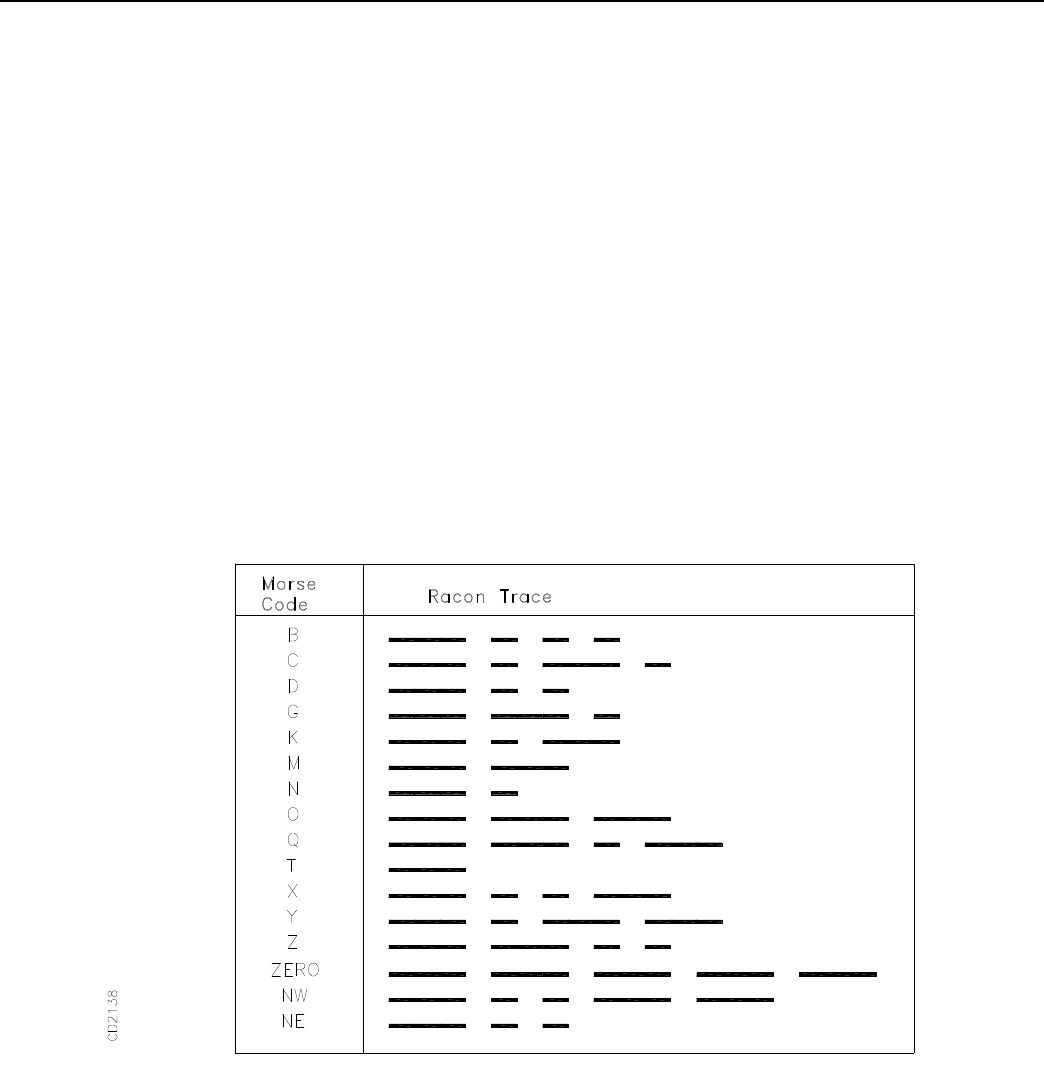
Any of the pre-programmed Morse code characters beginning with a dash (shown in Table 1.1) can be used
to identify the racon. The choice of code and of code character length is made by means of an external
handheld keypad or computer terminal.
Table 1.1 Racon Codes

SeaBeacon 2 System 6 General Information
Tideland Signal Corporation 3
1.1.2 Mechanical Features
The major assemblies of the racon are a base housing/chassis assembly that contains the electronics, the X-
band and S-band antennas, and a radome that provides weather protection for the antennas.
The base housing is cast from marine grade aluminum. On the outside, the housing is painted with Corthane
enamel. The radome is attached to the housing and sealed by means of an airtight O-ring. This arrangement
protects the internal assemblies from saltwater intrustion. Sealed cable connectors assure submersibility at
water depths up to 10 meters (35 ft).
The reliability of the circuit interconnections is enhanced by the use of a printed circuit backplane and
connectors with gold-plated contacts.
The radome is made from gray polycarbonate structural foam, a material that is highly transparent to micro-
wave energy and remains stable under ultraviolet radiation. The exterior of the radome is coated to seal the
structural foam and painted with polyurethane enamel.
1.1.3 Input Power Requirements
The SeaBeacon 2 System 6 racon requires an input voltage of 9 to 36 volts DC that can be supplied by
several types of DC power sources. An AC-powered battery charger and storage battery combination is a
reliable method of obtaining unlimited power to operate the racon. In remote locations where AC mains
power is not available, the racon can be powered by a photovoltaic generator coupled to a 12 volt or 24 volt
battery. Under all conditions, the effective source impedance of the voltage supply must be less than 0.05
Ohm.
Under limited-power conditions, racon power consumption becomes an important factor. The power man-
agement feature of the SeaBeacon 2 System 6 racon ensures minimum power consumption.

1.2 INQUIRIES
The following Tideland facilities may be contacted for replacement parts or maintenance support.
Tideland Signal Limited
15-19 Trowers Way
Redhill, Surrey, RH1 2LH, England
PH: +44 (0) 1737-768211
FX: + 44 (0) 1737-768192
E-mail: sales@tidelandsignal.ltd.uk
Tideland Signal Pte. Ltd.
Crystal Time Building
16 Tannery Lane #04-00
Singapore 347778
PH: + 65 6333-0078
FX: + 65 6333-0079
E-mail: sales@tidelandsignal.com.sg
Tideland Signal
708 Beau Pre Road
Lafayette, LA 70508, USA
PH: + 1 (337) 269-9113
FX: + 1 (337) 269-9052
E-mail: sales@lafayette.tidelandsignal.com
The corporate headquarters depot repair facility is located at:
Tideland Signal Corporation
4310 Directors Row
Houston, Texas 77092, USA
PH: + 1 (713) 681-6101
FX: + 1 (713) 681-6233
E-mail: hq@tidelandsignal.com
http://www.tidelandsignal.com
Should you need to return a SeaBeacon 2 System 6 racon for repair, you must obtain a Return Material
Authorization number prior to shipping. Contact your nearest Tideland representative for instructions.
General Information SeaBeacon 2 System 6
4Tideland Signal Corporation

CHAPTER 2
INSTALLATION
2.1 INITIAL INSPECTION
Initial inspection of a SeaBeacon 2 System 6 racon is a three step process: receiving, unpacking, and visually
inspecting the racon.
Receiving:
When the SeaBeacon 2 System 6 racon arrives, make note of any physical damage to the exterior of
the shipping container. Exterior damage may be the only clue to possible interior damage caused by
rough handling in shipment.
Unpacking:
Unpack the racon carefully without damaging the shipping container. The container has custom
designed cavities that conform to the shape of the racon. Save it for future use in shipping the racon.
Visual Inspection:
After the unit is unpacked, visually inspect the racon for obvious damage. Check that all associated
hardware is accounted for and damage free.
2.2 INSTALLATION MATERIALS SUPPLIED
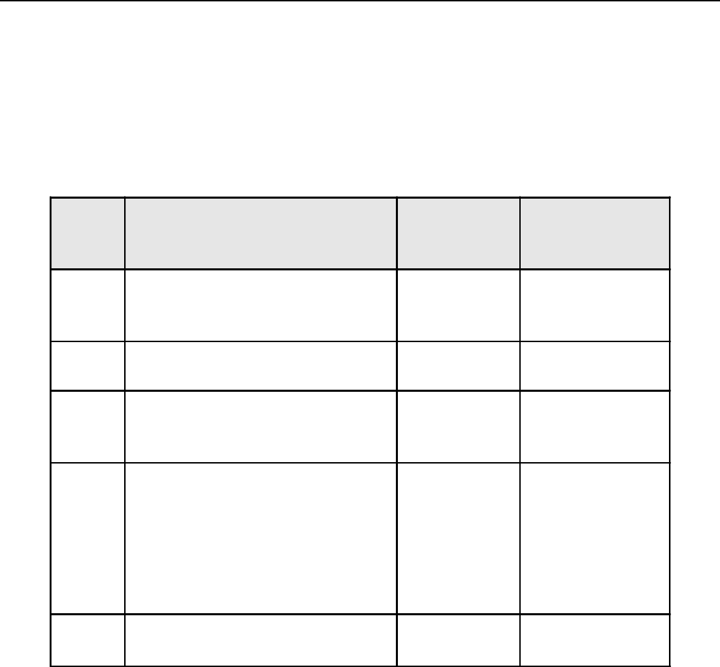
Table 2.1 identifies the contents of the shipping container. All materials required for normal installation are
included in the shipping container. At some sites there may be a need for a mechanical lifting device to
position and hold the racon in place prior to installing the mounting hardware.
SeaBeacon 2 System 6 Installation
Tideland Signal Corporation 5
Installation SeaBeacon 2 System 6
6Tideland Signal Corporation
2.3 INSTALLATION CONSIDERATIONS
In planning the installation of a SeaBeacon 2 System 6 racon, consider the requirements for level installa-
tion, proper orientation of the racon, and possible obstructions to its operation.
NOTE:All pre-installation adjustments are performed in the factory. Further adjustments prior to installation
in the field are not necessary.
Table 2.1 Contents of the SeaBeacon 2 System 6 Shipping Container
QTY NAME TIDELAND
PART
NUMBER PURPOSE
1SeaBeacon 2 System 6 Racon (GMU)
X+S-Band
070.1011-10
1Power & Data Cable Assembly, Ext. 510.1235-00
1External Cable Tag 304.1565-00 Identifies conductor
color and signal for
connector pins.
1
4
6
9
12
3
4
Leveling/Mounting Kit consisting of:
M10 X 1.5 X 100mm Hex Head Bolt
M10 Split Lock Washer
M10 Flat Washer
M10 X 1.5 Hex Nut
M10 External Star Lock Washer
M10 X 1.5 Hex Nylok Nut
901.1042-00
211.1467-00
233.1043-00
230.1034-00
221.1064-00
232.1008-00
221.1055-00
Secures racon to
mounting surface.
1SeaBeacon 2 System 6 Racon
Installation Manual 011.1181-00 Installation
instructions.

SeaBeacon 2 System 6 Installation
Tideland Signal Corporation 7
Site:
The racon must be leveled. For fixed mounting surfaces, install the racon within 1 degree of true
vertical. For installation on buoys, just mount the racon upright.
For best results, locate the racon as high as practical in order to provide a clear line-of-sight path
between the racon and the marine radar. In general, the higher the racon is mounted, the better is its
useful range.
For example, a ship’s radar antenna is 15 meters (50 ft) above water, and the highest point of land the
vessel is approaching is 91 meters (300 ft) resulting in a nominal radar range of approximately 28
nautical miles.
[
]
TRTXNM HHR+= 08.2
R is in Nautical Miles
HTX and HTR are Heights in Meters
For more information about racon range estimates, please see the IALA publication “Guidelines on
Racon Range Performance”, December 1999.
Orientation:
The racon must be mounted vertically. The orientation arrows on the lift ring and housing (opposite
the connectors) must align and should point seaward or toward the longest range of the traffic service
area.
Record of Obstruction:
Create a record of the installation that notes the date of installation and any obstructions that exist
between the racon and the sea lanes where ship traffic of interest will pass. Retain this record and
refer to it periodically to determine whether any new construction is interfering with racon perfor-
mance to the extent that relocation may be advisable.

Installation SeaBeacon 2 System 6
8Tideland Signal Corporation
WARNING
To avoid personal injury, use care in standing on the
racon support structure. The footing on the support
structure may be covered with slippery marine growth.
DO NOT use the racon as a step-up ladder. The
housing will not support your weight.
2.4 MECHANICAL MOUNTING PROCEDURES
The racon can be mounted either on a flat and level surface with 4-hole mounting or on a non-level or non-
flat surface with 3-hole mounting; however, the racon itself must be leveled. If the mounting surface is level,
follow the procedure below to mount the racon. If the mounting surface is not level, follow the alternate
procedure to non-level mounting surfaces.
Level Mounting Surface:
Follow the steps below to mount a racon onto a flat and level surface. Refer to Figures 2.1 and 2.2 for
mounting details and mounting hardware.
1. Locate the leveling/mounting kit (P.N. 901.1042-00). See Figure 2.2 to identify the mounting hard-
ware required for level mounting.
2. Drill four 13 mm (0.5 in) diameter holes in the mounting surface (pedestal or flange) to which the
racon will be affixed. In the plastic sleeve at the back of this manual is a 1:1 drawing for use as a
template for drilling the holes (see Tideland drawing 901.1042-00, sheet 2 of 2).
SeaBeacon 2 System 6 Installation
Tideland Signal Corporation 9
5. Tighten the nuts in the alternating bolt fastening sequence shown on Figure 2.1 to an initial torque of
13 62.5 N-m (10 62 ft lb).
6. In the same sequence, tighten the bolts to a final torque of 40 62.5 N-m (30 62 ft lb).
CAUTION
The Ground Strap must securely connect to a earth
ground for lightning protection.
3. Using the lift ring provided, lift the racon and set it on hte mounting surface so that the holes in the
racon base are aligned with the holes drilled in the mounting surface. To simplify hole alignment, use
one or two mounting bolts as temporary alignment pins.
4. Insert a hex head bolt in position 1 (see Figure 2.1), first through the racon base and then through the
mounting surface. From underneath the mounting surface, install a flat washer, a split-lock washer,
and a hex nut on the head bolt. An optional hex nylok nut may be added (see Figure 2.2). The earth
ground connection for lightning protection is made on a stud mounted on the racon base housing
mounting flange.
Non-Level Mounting Surface:
Follow the steps below to mount a racon on a non-level or not flat surface. Refer to Figures 2.1 and 2.3 for
mounting details and leveling hardware.
1. Locate the following items required for leveling:
•Leveling/mounting kit (P.N. 901.1042-00)
•Carpenters level (1 each)
•Open-end wrench, 17 mm (2 each)
2. Drill three 13 mm (0.5 in) diameter holes in the mounting surface (pedestal or flange) to which the
racon will be affixed. In the plastic sleeve at the back of this manual is a 1:1 drawing for use as a
template for drilling the holes (see Tideland drawing 901.1042-00, sheet 1 of 2).
3. Using the lift ring provided, lift the racon and set it on the mounting surface so that the holes in the
racon base are aligned with the holes drilled in the mounting surface. To simplify hole alignment, use
one or two mounting bolts as temporary alignment pins.

Installation
SeaBeacon 2
System 6
10 Tideland Signal Corporation
4. Assemble the leveling bolts as shown in Figure 2.3: Insert a hex head bolt through the racon base in
position 1 (see Figure 2.1). From underneath the racon base, install a flat washer, a split-lock washer,
two hex nuts, an exterior star lock washer, a hex nut, and a flat washer. Insert this bolt assembly
through the mounting surface (position 1). From underneath the mounting surface, install a flat
washer, a split-lock washer, and a hex nut. An optional hex nylok nut may be added (see Figure 2.3).
The earth ground connection for lightning protection is made on a stud mounted on the racon base
housing mounting flange.
In the same manner, install the other two leveling bolts in positions 3 and 5 (see Figure 2.1).
CAUTION
The Ground Strap must securely connect to a earth
ground for lightning protection.
5. Tighten the top nut of each bolt assembly against the mounting flange of the racon to a torque of 11
60.7 N-m (8 60.5 ft lb). This will secure the hardware to the racon.
6. Visually level the racon by adjusting the bottom and middle nuts as required.
7. Place the carpenter’s level on the X-axis of the racon lift ring.
8. Adjust the hardware as required until the bubble is centered within the marked circle.
9. Reposition the level to the Y-axis and adjust hardware as required to center the bubble.
10. Recheck the X-axis and adjust as required.
11. Repeat steps 7 through 10 as required.
12. Using the tightening sequence shown in Figure 2.1, tighten the two bottom nuts of each bolt assem-
bly to a torque of 40 62.5 N-m (30 62 ft lb) and recheck level of racon.
SeaBeacon 2 System 6 Installation
Tideland Signal Corporation 11
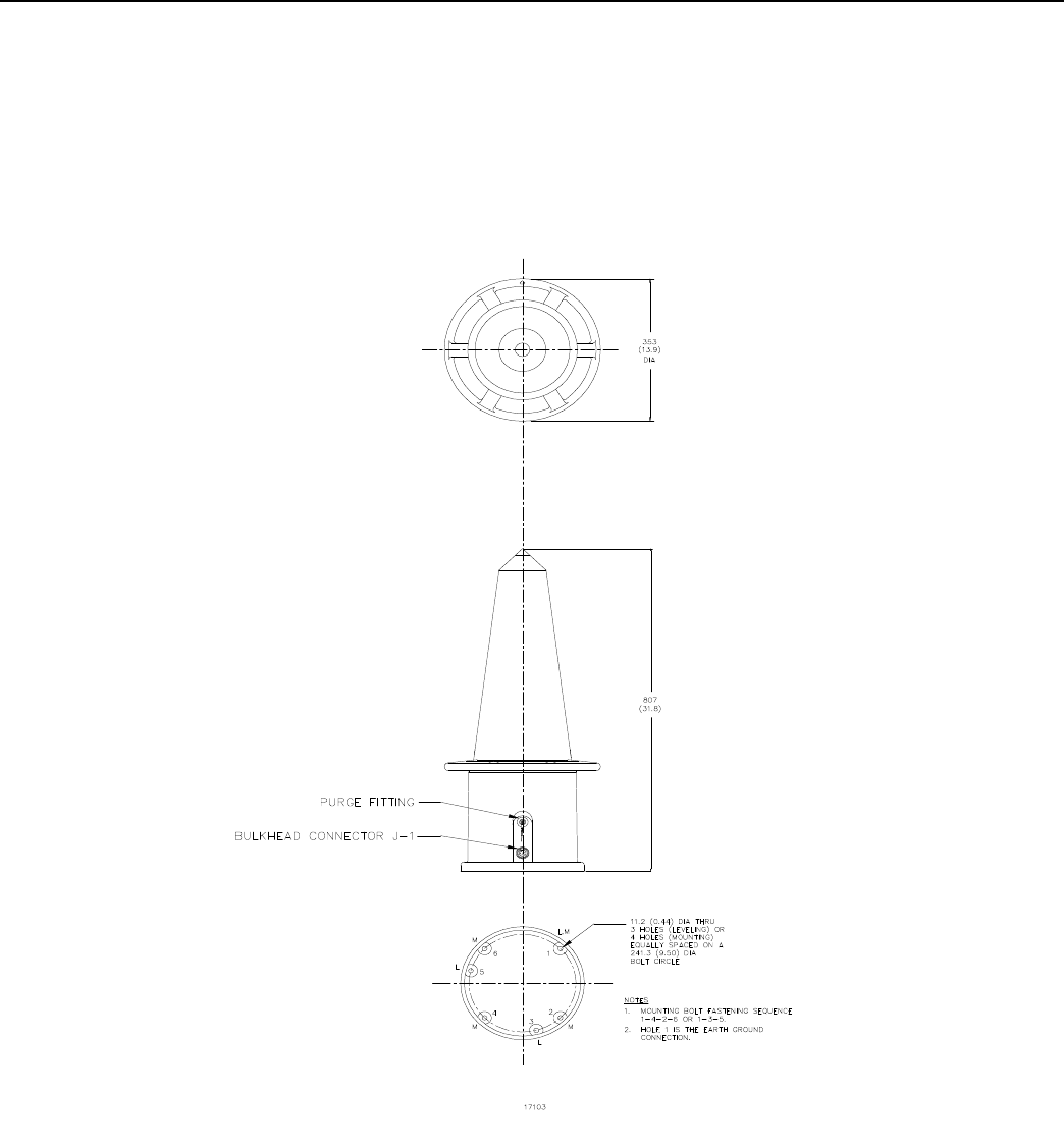
Figure 2.1 Racon Mounting Detail
Installation SeaBeacon 2 System 6
12 Tideland Signal Corporation
Figure 2.2 Mounting Hardware
SeaBeacon 2 System 6 Installation
Tideland Signal Corporation 13
Figure 2.3 Leveling Hardware

Installation SeaBeacon 2 System 6
14 Tideland Signal Corporation
2.5 ELECTRICAL CONNECTIONS
2.5.1 DC Power Cable Limitations
The SeaBeacon 2 System 6 racon must have a minimum 9 VDC input at the connector terminals in the racon
base housing to operate properly. This means there is a practical limit on the total cable run from the battery
to the racon, especially for 12 VDC batteries.
The power cable run consists of two sections of cable: the cable P.N. 510.1235-00 (or -01) that ships with
the racon, and a second cable between the racon junction box or distribution box and the battery, whose
length and size is usually determined by the installer.
2.5.1.1 12 VDC Power System
The Tideland cable uses #12 AWG copper wire for power conductors. Assuming a worst case peak instanta-
neous current of 15A in the cable, and a loaded battery voltage of 11.0 VDC (based on a nearly discharged
battery), the overall allowable cabling loss is 2.0 V. Assuming a safety factor of 0.3 V for miscellaneous
losses in field connections, the design loss in all of the copper wiring must be limited to 1.7 VDC at 15A.
The 16 foot Tideland cable P.N. 510.1235-00 will contribute a loss of 0.78 V. The remaining allowable loss
in the other cable is then:
1.7 - 0.78 = 0.92 V
The 50 foot version of the Tideland supplied cable (P.N. 510.1235-01) will contribute a loss of 2.43 V.
Therefore, the 50 foot cable is not recommended at all for use in installations with 12 VDC batteries. Table
2.2 shows the cable limitations for connecting a 12 VDC battery to the racon junction box.

SeaBeacon 2 System 6 Installation
Tideland Signal Corporation 15
Table 2.2 Cable Limitations for 12 VDC Battery Systems
WIRE SIZE RESISTIVITY,
OHM/1000
FEET MAXIMUM LENGTH OF CABLE (FEET)
25 mm sq 0.222 140
#4 AWG 0.253 123
16 mm sq 0.351 88
#6 AWG 0.403 77
10 mm sq 0.558 56
#8 AWG 0.641 48
6 mm sq 0.939 33
#10 AWG 1.02 30
4 mm sq 1.41 22
#12 AWG 1.62 19
2.5 mm sq 2.26 14
#14 AWG 2.58 12

Installation SeaBeacon 2 System 6
16 Tideland Signal Corporation
22.0 - 4.0 = 18.0 VDC
At 18 VDC, the worst case peak instantaneous current in the cable is 10A. The 16 foot Tideland cable P.N.
510.1235-00 will contribute a loss of 0.52 V. The 50 foot version of the Tideland cable P.N. 510.1235-01
will contribute a loss of 1.62 V. The remaining allowable loss in the other cable is then:
3.7 - 0.52 = 3.18 V, when the 16 foot cable is used, and
3.7 - 1.62 = 2.08 V, when the 50 foot cable is used
Table 2.3 shows the cable limitations for connecting a 24 VDC battery to the racon junction box.
2.5.1.2 24 VDC Power System
Assuming a loaded battery voltage of 22.0 VDC (based on a nearly discharged battery), the overall theoreti-
cal allowable cabling loss is 13.0 V. However, Tideland recommends limiting the practical overall cabling
losses to 4.0 V maximum for optimum operation. Assuming a safety factor of 0.3 V for miscellaneous losses
in field connections, the design loss in all of the copper wiring must be limited to 3.7 VDC. The minimum
input voltage at the base housing of the racon is then approximately:

SeaBeacon 2 System 6 Installation
Tideland Signal Corporation 17
Tideland racon junction or distribution boxes can accept a maximum wire size of #10 AWG or 6 mm2 sq. If
conductors larger than this must be used for the battery cable, an intermediate junction box will be required
to make the wiring transition to the Tideland junction box or distribution box.
Table 2.3 Cable Limitations for 24 VDC Battery Systems
WIRE SIZE RESISTIVITY,
OHM/1000
FEET
MAXIMUM LENGTH OF CABLE (feet)
16 FT. CABLE 50 FT. CABLE
P.N. 510.1235-00 P.N. 510.1235-01
25 mm sq 0.222 716 468
#4 AWG 0.253 628 411
16 mm sq 0.351 453 296
#6 AWG 0.403 395 258
10 mm sq 0.558 285 186
#8 AWG 0.641 248 162
6 mm sq 0.939 169 111
#10 AWG 1.02 156 102
4 mm sq 1.41 113 74
#12 AWG 1.62 98 64
2.5 mm sq 2.26 70 46
#14 AWG 2.58 62 40

Installation
SeaBeacon 2
System 6
18 Tideland Signal Corporation
2.5.2 Electrical Connection Procedure
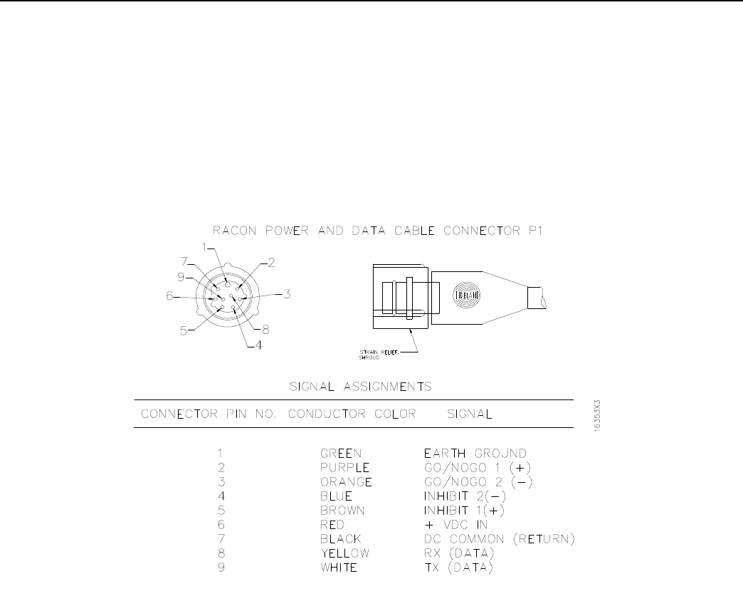
Electrical connections required for power, control, status, and communications are shown in Figures 2.6 and
2.9. If the installation requires power and data connection arrangements other than through the junction box
shown in Figure 2.6 or the distribution box shown in Figure 2.9, refer to Figure 2.4 for connection assign-
ments. The Tideland power and data cable has pig-tail leads on one end, which are adaptable to any other
connector.
The SeaBeacon 2 System 6 racon is designed to have the negative (-) side of the power supply connected to
the negative (-) side of the battery which should be earth grounded.
The following steps explain how to make connections when using Tideland junction boxes or distribution
boxes.
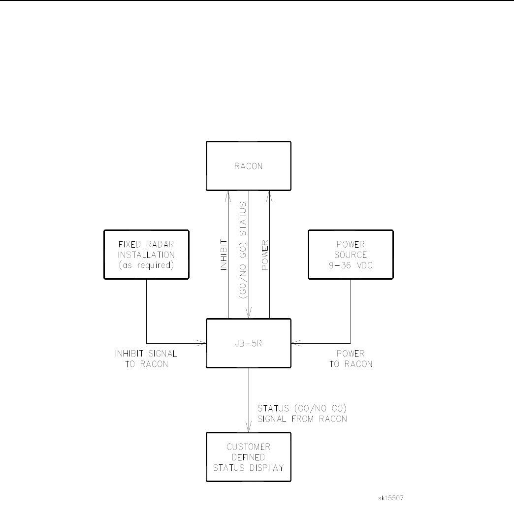
1. The standard junction box for the SeaBeacon 2 System 6 racon is the JB-5R Junction Box (P.N.
630.1169-00). If the racon is to be used with blanking (Inhibit) or communications, however, it
requires the DB-5P Distribution Box (P.N. 630.1187-06). Determine which box is to be used with the
system and refer to the associated figures and connection tables on the following pages. For the JB-
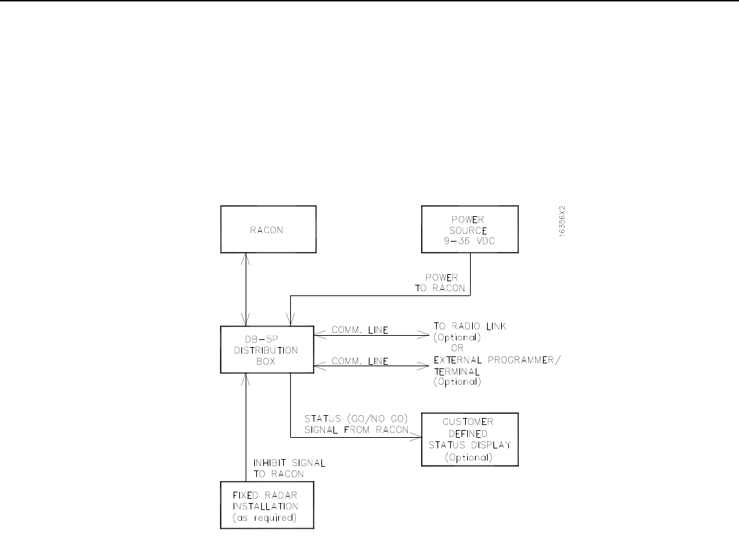
5R box, refer to the block diagram in Figure 2.5 and to the block diagram in Figure 2.8 and the
wiring diagram in Figure 2.9.
2. Locate the appropriate box and mount it. See Figure 2.7 for JB-5R mounting dimensions and Figure
2.10 for DB-5P mounting dimensions.
NOTE: The power and data cable supplied (P.N. 510.1235-00) is 4.5 meters (15 ft) long.
3. Pass the racon power and data cable through the appropriate gland and terminate the wires as shown
in the appropriate figures and tables (Figure 2.6 and Table 2.2 for the JB-5R, or Figure 2.9 and Tables
2.3 through 2.6 for the DB-5P). For the JB-5R box, install the crimp-on terminals provided before
terminating the wires to the terminal strip. Tighten the gland nut securely.
4. Connect the DC power line and all other lines to options according to the wiring diagram for the box
used. For the installation of the blanking or the GO/NO GO option, refer to Section 2.6. If possible,
install a disconnect switch for the DC power line at the power source. With a disconnect switch
installed, turn the power off. If a disconnect switch cannot be installed, use care when connecting the
power and data cable to the racon. Do not proceed to step 5 until the racon is ready to be energized.
Securely tighten all gland nuts.
5. Remove the dust cap from the bulkhead connector (J-1) on the racon (see Figure 2.1). Retain the dust
cap for later use if the racon should have to be shipped. Connect cable connector P-1 (Figure 2.4) to
the bulkhead connector. Mate the connectors and apply moderate force until they seat. There will be
some resistance because the connection is designed to be watertight.

SeaBeacon 2 System 6 Installation
Tideland Signal Corporation 19
While pushing cable connector P-1 into place, rotate the locking ring clockwise. Hand-tighten the locking
ring until it is flush with the base of J-1.
6. If you turned the power off in step 4 above, now turn it on. At this point, the racon is ready to oper-
ate.
NOTE: The power input to the racon is completely protected internally from reverse polarity, high volt
age, power surges, lightning, and AC ripple.
It is imperative that the grounding strap has a secure connection to earth ground.
A suitable connection that can sustain adverse effects from the environment (temperature, humidity, vibra-
tion, shock, and salt spray) is required.
The resistance from the metal terminal at the base must be less than 1 Ohm to earth ground.
CAUTION
The Ground Strap must securely connect to a earth ground
for lightning protection.
Installation SeaBeacon 2 System 6
20 Tideland Signal Corporation
Figure 2.4 Signal Assignments for Racon Power and Data Cable
SeaBeacon 2 System 6 Installation
Tideland Signal Corporation 21
Figure 2.5 Standard Power and Data Input/Output
Installation SeaBeacon 2 System 6
22 Tideland Signal Corporation
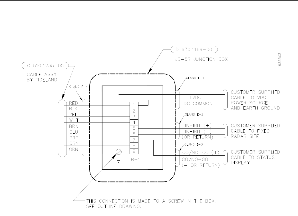
Figure 2.6 Field Wiring for Standard JB-5R Junction Box

SeaBeacon 2 System 6 Installation
Tideland Signal Corporation 23
Table 2.4 TB-1 Connections (JB-5R Box)
P.N. 510.1235-00
COLOR SIGNAL
NAME TERMINAL
NUMBER TYPE OF
CRIMP-ON USER COLOR
CODES*
Green Earth Ground screw into box Ring
Red (+) Battery Terminal 1Fork
Black (-) Battery Terminal 2Fork
Yellow Rx data 3Fork
White Tx data 4Fork
Brown Inhibit (+)** 5Fork
Blue Inhibit (-)** 6Fork
Purple GO/NO GO (+)** 7Fork
Orange GO/NO GO (-)** 8Fork
* To be filled in by the installer
** See Section 2.6 for a discussion of fixed radar blanking and status display (GO/NO GO).
NOTE:The strip length for the cable jacket is 125 mm (5 in). The conductor strip length is 6 mm (0.25 in).
Fit the conductors with the supplied termination fittings.
Installation SeaBeacon 2 System 6
24 Tideland Signal Corporation
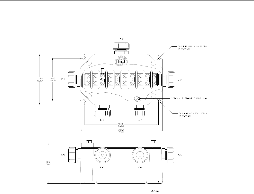
Figure 2.7 Mounting Dimensions for JB-5R Junction Box
SeaBeacon 2 System 6 Installation
Tideland Signal Corporation 25
Figure 2.8 External Communication Option, Block Diagram
Installation SeaBeacon 2 System 6
26 Tideland Signal Corporation
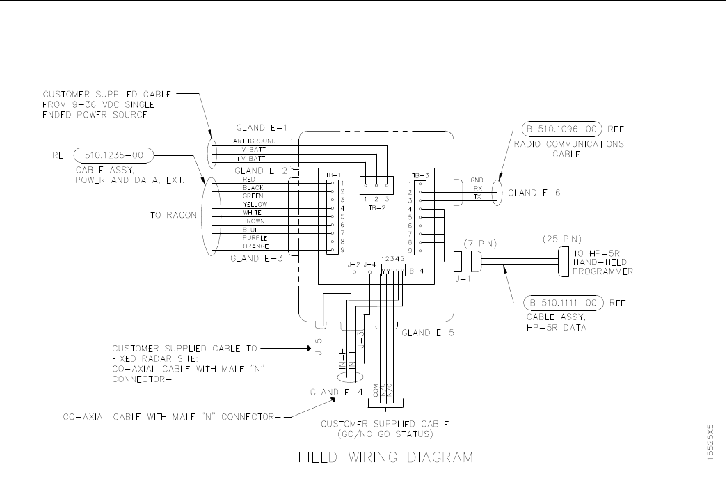
Figure 2.9 Field Wiring for External Communication Option, DB-5P Distribution Box

SeaBeacon 2 System 6 Installation
Tideland Signal Corporation 27
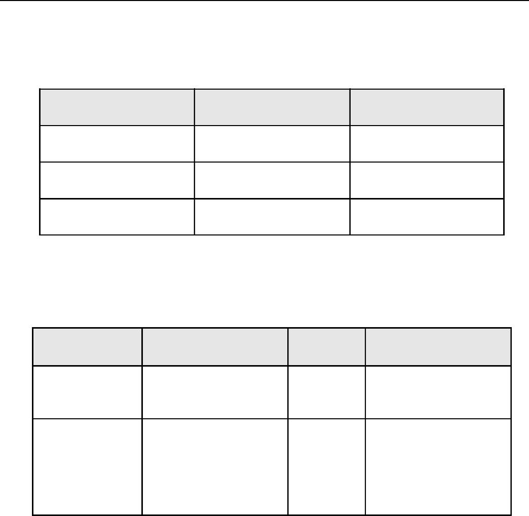
Table 2.5 TB-1 Connections (DB-5P Box)
COLOR SIGNAL NAME TERMINAL NUMBER
Red (+) Battery Terminal 1
Black (-) Battery Terminal 2
Green Earth ground 3
Yellow Rx data 4
White Tx data 5
Brown Inhibit (+)** 6
Blue Inhibit (-)** 7
Purple GO/NO GO (+)** 8
Orange GO/NO GO (-)** 9
** See Section 2.6 for a discussion of fixed radar blanking and status display (GO/NO GO).
NOTE:The strip length for the cable jacket is 100 mm (4 in). The conductor strip length is 6 mm (0.25 in).
Installation SeaBeacon 2 System 6
28 Tideland Signal Corporation
Table 2.6 TB-2 Connections (DB-5P Box)
COLOR* SIGNAL NAME TERMINAL NUMBER
(+) VDC 1
DC Common (return) 2
Earth ground 3
* Customer to define.
Table 2.7 TB-3 Connections (DB-5P Box)
COLOR SIGNAL NAME TERMINAL
NUMBER
Brown
Black
Red
Earth ground
Tx data
Rx data
1
2
3
To radio communications
(system option)
White
Green
Brown
Red
Blue
Black
Earth ground
Tx data
Rx data
(+) Battery Terminal
(+) Battery Terminal to K-1
DC Common (return)
4
5
6
7
8
9
Communication and Power
to External Programmer
(wiring by Tideland)
SeaBeacon 2 System 6 Installation
Tideland Signal Corporation 29
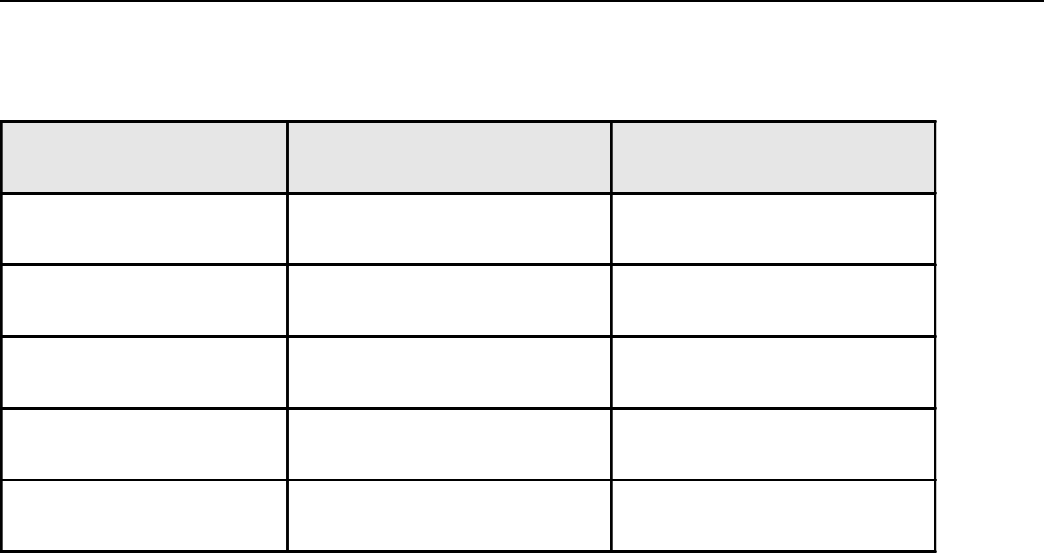
Table 2.8 TB-4 Connections (DB-5P Box)
COLOR* SIGNAL NAME TERMINAL NUMBER
GO/NO GO (-)** 1 Common
GO/NO GO (+)** 2 Normally Closed
GO/NO GO (+)** 3 Normally Opened
Inhibit (-)** 4
Inhibit (+)** 5
* Customer to define.
** See Section 2.6 for a discussion of fixed radar blanking and status display (GO/NO GO).
Installation SeaBeacon 2 System 6
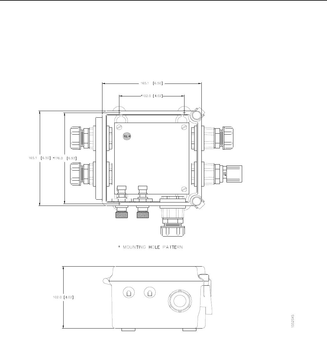
30 Tideland Signal Corporation
Figure 2.10 Mounting Dimensions for DB-5P Distribution Box
SeaBeacon 2 System 6 Installation
Tideland Signal Corporation 31
2.6 BLANKING AND STATUS DISPLAY
2.6.1 Inhibiting Racon Response to a Fixed Radar
Blanking is a useful function when there are fixed radars within the SeaBeacon 2 System 6 racon service area
from which a racon response would serve no purpose. A detrimental effect would be additional power
consumption. The SeaBeacon 2 System 6 racon can be inhibited from responding to fixed radars by connect-
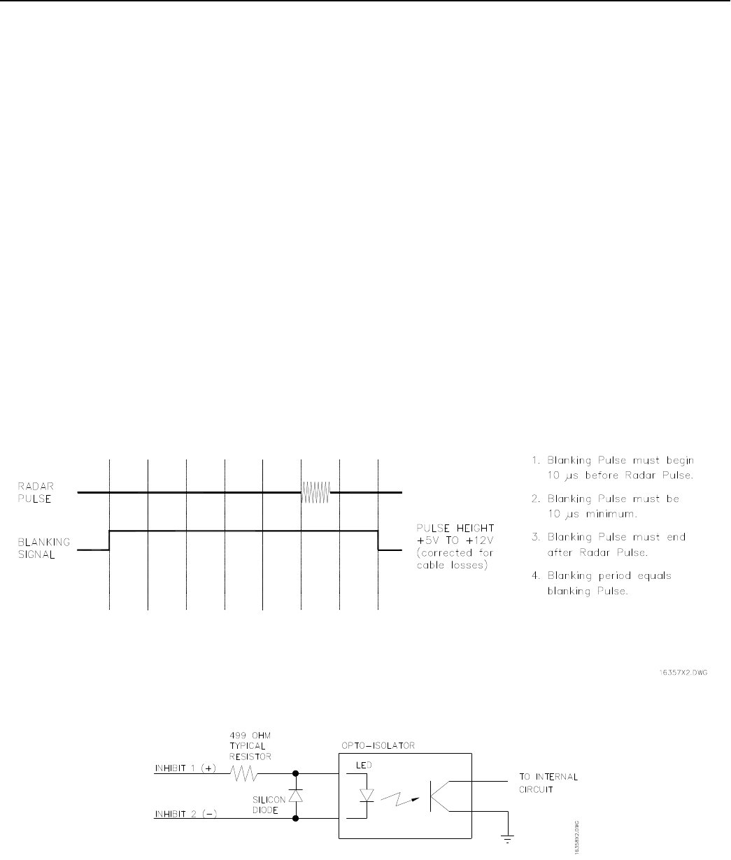
ing a blanking control signal from the fixed radar to the racon. The blanking signal must have the character-
istics shown in Figure 2.11.
The blanking signal must be connected to the SeaBeacon 2 System 6 racon on the INHIBIT (+) and the
INHIBIT (-) lines of the power and data cable (P.N. 510.1235-00). The blanking circuit in the racon uses a
high speed optocoupler and is functionally equivalent to the circuit in Figure 2.12.
If a single radar is in the service area, either the JB-5R junction box or the DB-5P distribution box may be
used. In either case, the external blanking signal from the radar is connected to the Inhibit opto-isolator of
the SeaBeacon 2 System 6 racon. If two radars are in the service area (for example, a nearby installation has a
X-band and S-band radar) the DB-5P distribution box must be used. The external blanking signals must be
routed via the N Type connectors. Either radar may be connected to either N Type connector. The driver
requirements are the same for both radars.
Figure 2.11 Blanking Pulse Characteristics
Figure 2.12 Functionally Equivalent Blanking Circuit
SeaBeacon 2 System 6 Operation
Tideland Signal Corporation 32
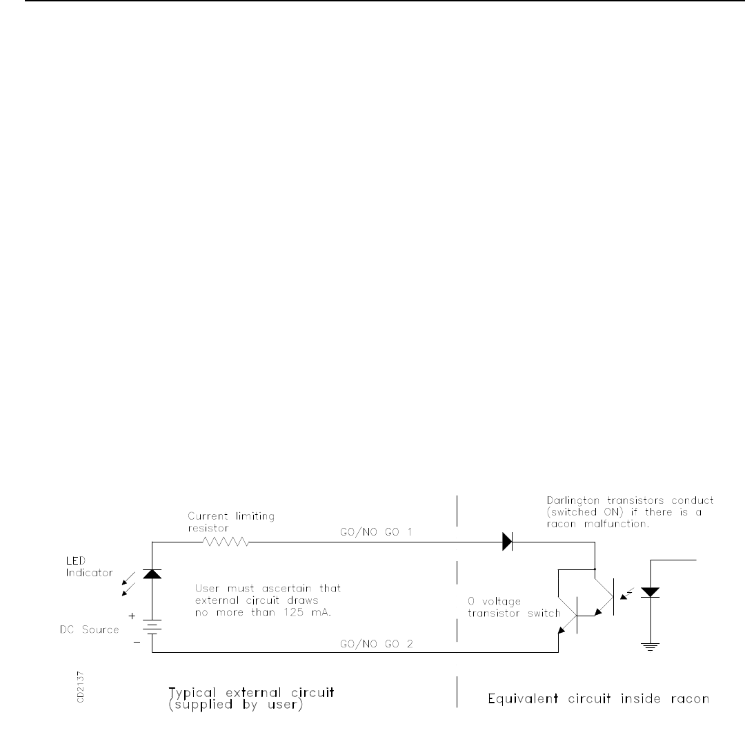
2.6.2 Status Display
The status display lines (GO/NO GO + and -) provide a means of continuously monitoring whether or not
the racon is functional. Figure 2.13 shows a functionally equivalent circuit along with a suggested method
for implementing the GO/NO GO function. The circuit can switch an outside current source of 1.5 mA or
less. This low current drives a transistor switch in the distribution box.
The polarity or signal sense that the SeaBeacon 2 System 6 racon provides is user selectable. The opto-
isolator is normally turned on only if there is a racon malfunction. This method minimizes supply current.
Use of the DB-5P junction box is encouraged.
The DB-5P distribution junction box contains a GO/NO GO relay with a form C contact output. Either a
normally closed or a normally open contact, rated at 1 Amp/120 Volt maximum AC or DC, may be selected.
Figure 2.13 The GO/NO GO Circuit

SeaBeacon 2 System 6 Operation
Tideland Signal Corporation 33
CAUTION
To prevent damage to the racon, do not under any
circumstances break the seal of the racon in the field.
2.7.1 Dismounting
The dismounting procedure is the reverse of the mounting procedure. Disconnect the electrical connections
first, and then remove the mounting hardware and retain it with the racon.
2.7.2 Preparation for Shipment
Place the dust cap on the bulkhead connector J-1 on the racon. The shipping container for the racon has
internal cavities that conform to the shape of the racon. Use the original shipping container to pack the racon
for reshipment.
2.7.3 Shipping
Should the SeaBeacon 2 System 6 racon need to be returned for any reason, obtain a Return Material Autho-
rization number from Tideland prior to shipping. Contact your nearest Tideland representative for instruc-
tions.
Facilities authorized to repair the SeaBeacon 2 System 6 racon are listed in Chapter 1, Section 1.2.
2.7 DISMOUNTING AND SHIPPING THE RACON
In the event the racon needs to be returned to the intermediate repair facility for maintenance, use the follow-
ing procedures for dismounting and shipping the racon.

Installation SeaBeacon 2 System 6
34 Tideland Signal Corporation

SeaBeacon 2 System 6 Operation
Tideland Signal Corporation 35
CHAPTER 3
OPERATION
3.1 INTRODUCTION
The SeaBeacon 2 System 6 racon has been configured at the factory with the standard settings listed in Table
3.1 unless otherwise specified at time of purchase.
The user interface of the SeaBeacon 2 System 6 racon allows the user to change the operating characteristics
of the racon to meet his particular requirements. Also, the user can command the racon to perform internal
tests for maintenance and diagnostic purposes.
The user communicates with the racon by using an external terminal to enable features or specify operating
values to the racon. The external terminal can be any ANSI compatible ASCII terminal, including computers
running terminal emulation programs such as HYPERTERM.
The external terminal allows you to test the SeaBeacon 2 System 6 racon in the field or shop without opening
the racon. When you connect the external terminal to the racon, turn it on, and set it for terminal mode, the
power management system completes its cycle and then goes into the Listen state. This activates the termi-
nal. The racon will remain in the Listen state until the keypad or keyboard is turned off and power manage-
ment resumes or until the racon times out due to a lack of keyboard activity (after 5 minutes).
3.2 SETUP PROCEDURES
3.2.1 External Computer Terminal
3.2.1.1 Connecting a Computer Terminal to the SeaBeacon 2 System 6 Racon
A cable with a DB25 connector (to connect to the racon) and an appropriate connector on the other end for
the user’s terminal (typically a 9- or 25-pin connector) is required to connect the computer terminal to the
racon.
Operation SeaBeacon 2 System 6
36 Tideland Signal Corporation
PIN # DESCRIPTION
1Frame ground
2Tx data (data to terminal from racon)
3Rx data (data from terminal to racon)
7Signal ground
Table 3.1 Standard Factory Settings for SeaBeacon 2 System 6 Racon
If a terminal emulation program is being used, a null modem cable or null modem adaptor is also required. A
null modem reverses pins 2 and 3 (Rx data and Tx data). The pin assignments for the 25-pin connector are as
follows:
SeaBeacon 2 System 6 Operation
Tideland Signal Corporation 37
Communications parameters should be set as follows:
3.2.1.2 Computer Terminal Setup Routine (Connected to the Racon)
If using a computer terminal, turn it on or start the terminal emulation program and type the letter [O] to
enable the keyboard.
To communicate with the racon, press the letter [O] within 4 seconds of either the beeps or the SYSTEM
OK update message. (If you do not press [O] within 4 seconds of the beep or SYSTEM OK, wait one com-
plete power management cycle and then press [O] within 4 seconds of the next beep or SYSTEM OK.) A
complete power management cycle is the duty cycle of the racon: the sum of the Active ON and the Standby
OFF times. The standard factory setting is 40 seconds.
If you do not want to continue to perform another User Function, turn the keyboard off by pressing the letter
[O].
Baud rate: 9600
Parity: None
Data bits: 8
Stop bits: 1
Echo: Host
CR, LF: No translation
Handshaking: None

Operation SeaBeacon 2 System 6
38 Tideland Signal Corporation
3.3 OPERATING INSTRUCTIONS
3.3.1 Description of Keys
Actual keys used in operating the external terminal are enclosed in brackets [ ]. Keys to be used and descrip-
tions of their uses are listed below:
KEYS USED FOR
EXTERNAL TERMINAL DESCRIPTION
Letter [O] OR [o] Turns keyboard ON or OFF; keyboard must be ON to use
functions; when not used, the keyboard automatically reverts to
OFF after a programmed timeout.
[ESC] or [*] Exits a function.
[<-, DEL Backspace] Deletes the last character entered on the display.
[ENTER][EXE] Transfers the displayed value into the racon; starts an action.
[<] or [,] Decrements the displayed value; moves between selections;
[EXE] or [ENTER] must be used to transfer the value into the
racon.
[>] or [.] Increments the displayed value; moves between selections;
[EXE] or [ENTER] must be used to transfer the value into the
racon.
[0] [1] [2] [3] [4] [5] [6] [7] [8]
[9] or [-] Enters digits into the display.
[/] Restores old entry value, quits the entry, moves to next entry;
this is essentially a "whoops" key or can be used to skip an
entry.
[;] [^] or [#] Restores old entry value, quits the entry, backs up to previous
menu entry.
NOTE: When the keyboard is ON the racon will not enter Standby, its lowest power state.

SeaBeacon 2 System 6 Operation
Tideland Signal Corporation 39
3.3.2 Definition of Set and Select
Definitions of Set and Select are as follows:
Select:The racon presents the user with a list from which a parameter can be chosen. Items are
displayed one at a time. The list can be viewed forwards or backwards using the [>] or [.] and
[<] or [,] keys respectively.
To choose an item from the list for use by the racon, press [ENTER].
To skip the selection, press [/].
To return to the USER FUNCTION prompt, press [ESC].
Set:The racon requires the user to enter a particular value. Press the [-] key (if needed), then press
the [0] through [9] keys as needed to form the value.
If wrong digits are entered, press [ûbackspace], to delete each of the digits entered.
To store the value into the racon, press [ENTER].
To skip the setting, press [/].
To return to the USER FUNCTION prompt, press [ESC].
3.3.3 User Functions
1 BAND ENABLE
Select band enable for each of X and S bands.
USE BAND using increment/decrement keys, select “YES” to use
Bank, or “NO” to disable band; X band default is “NO”;
S band default is “NO”

Operation SeaBeacon 2 System 6
40 Tideland Signal Corporation
3 DUTY CYCLE
Sets the active and standby times for the power management cycle and enables and sets the period for ex-
tended idle.
ACTIVE ON set in range of 4 to 60 seconds; default is 20 seconds.
STANDBY OFF set in range of 0 to 60 seconds; default is 20 seconds.
EXT ENABLE using increment/decrement keys, select “YES” for ex-
tended idle or “NO” for normal operation; default is “NO”.
EXT PERIOD set in range of 1 to 10 ACTIVE ON plus STANDBY OFF
cycles; default is 5.
NOTE: an EXT PERIOD setting of 1 with EXT ENABLE selected to
“YES” behaves as if EXT ENABLE is selected to “NO”.
4 RESPONSE CODE
Selects the response code, sets maximum response length and selects proportional response.
CODE using increment/decrement keys, select one of “B”, “C”, “D”, “G”,
“K”, “M”, “N”, “O”, “Q”, “T”, “X”, “Y”, “Z”, “0”, “NW” OR “NE”;
default is “Q”.
LENGTH set in range of 5 to 80 microseconds; default is 60.
PROPORTION using increment/decrement keys; select “YES” for propor-
tional or “NO” for fixed response length; default is “YES”.
NOTE: If LENGTH is set to below 20 microseconds, PROPORTION is
automatically selected to “NO”.
5 LOW BATTERY
Sets the battery voltage below which the racon will remain in STANDBY OFF.
ENABLE using increment/decrement keys, select “YES” to enable low
voltage cutoff; default is “YES”.
VOLTAGE set in range 9.0 to 36.0 volts; default is 11.2.

SeaBeacon 2 System 6 Operation
Tideland Signal Corporation 41
6 SELFTEST
SELFTEST STATUS displays the following results of the last selftest:
SELFTEST reports “FAIL” if any individual test has failed.
WATCHDOG reports “FAIL” if the watchdog timer did not time out
properly.
PROGRAM reports “FAIL” if the program ROM check code is not cor-
rect.
DATA reports “FAIL” if the program RAM fails testing.
CONFIG reports “FAIL” if the configuration storage EEPROM is cor-
rupted; default values will be substituted for corrupted areas. NOTE:
default values will not be written into the configuration EEPROM.
RUN SELFTEST runs complete selftest and calibration.
7 RACON MONITOR
TEMPERATURE in units of degrees C.
PRESSURE in units of kPa.
PRESSURE (25C) in units of kPa.
INPUT VOLTAGE in units of volts.
+3.3 VOLTS in units of volts.
+10 VOLTS in units of volts.
-3.3 VOLTS in units of volts.
VREF VOLTS in units of volts.
HOUR METER in units of hours (this HOP is for the user; Tideland has its
own HOP counter).

Operation SeaBeacon 2 System 6
42 Tideland Signal Corporation
8 TERMINAL DEVICE
Selects the terminal device and serial port rate.
TYPE using increment/decrement keys, select one of “PSION”,
“QTERM”, OR “PC”.
CHANGE BAUD using the increment/decrement keys, select “YES” to
change the serial port baud rate.
BAUD using the increment/decrement keys, select one of “300”, “600”,
“1200”, “2400”, “4800” or “9600” baud; default is “9600”.
9 NOGO SELECT
Selects the GO/NOGO signal to be either active during fault or active during normal operation.
ACTIVE NOGO using the increment/decrement keys, select “YES” for
active during fault (low power setting) or “NO” for active during normal
operation (fail safe setting)’ default is “YES”.
NOTE: when ACTIVE NOGO “YES” is selected, the racon indicates a
false GO if power has failed.

SeaBeacon 2 System 6 Operation
Tideland Signal Corporation 43
3.4 PURGING AND REPRESSURIZING
The SeaBeacon 2 System 6 racon is normally pressurized at the factory to prevent moisture intrusion. On
request, Tideland will provide unpressurized racons.
This section defines maintenance requirements for preventing moisture intrustion over the life of a pressur-
ized or unpressurized racon.
3.4.1 SeaBeacon 2 System 6 Racon Without Pressurization
An unpressurized racon is shipped from the factory with two packets of desiccant inside the racon housing.
This desiccant will protect the racon from moisture for at least one year.
3.4.2 SeaBeacon 2 System 6 Racon With Pressurization
The racon base housing/chassis assembly is pressurized at the factory with pure dry nitrogen to 35 6 5 kPa
(5 61 psig) to protect the internal electronic components from moisture intrustion.
The racon should be purged and repressurized periodically to ensure sufficient gas pressure. The required
purge kit is available as Tideland P.N. 901.1058-00. To perform the purge procedure, you should have a
cylinder of dry nitrogen gas, an adjustable pressure reducing valve, and adapters to connect the pressure
reducing valve to the gas cylinder.
The pressure reducing valve should have an inlet pressure range of 21,000 kPa (3000 psig) and a maximum
outlet pressure of 205 kPa (30 psig). The reducing valve should be equipped with inlet and outlet pressure
gauges of the appropriate ranges. The connection to the purge manifold is 0.25 inch NPT male thread.
Figure 3.2 depicts the connection of the purging equipment to the racon.
Perform the following purging and repressurizing procedure once a year to ensure that the racon is suffi-
ciently pressurized.

Operation SeaBeacon 2 System 6
44 Tideland Signal Corporation
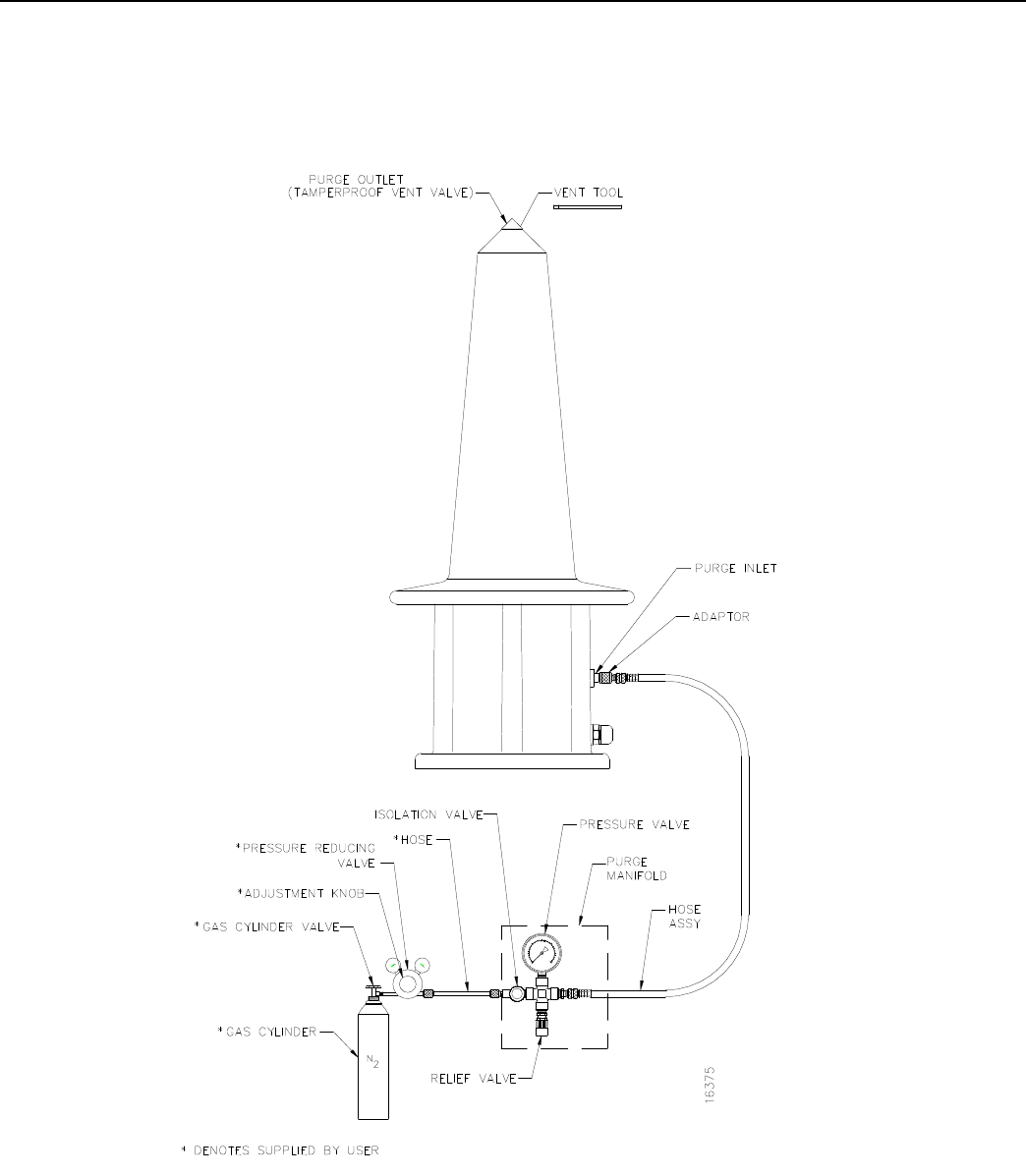
3.4.3 Purging Operation
1. Assemble the purge kit components, the pressure reducing valve, and the gas cylinder as shown in
Figure 3.1. Do not connect the manifold outlet hose to the adaptor fitting at this time.
2. Remove the cap covering the purge inlet fitting and carefully connect the adaptor fitting to the purge
inlet.
3. Turn the adjustment know on the pressure reducing valve to the minimum setting. Slowly open the
gas cylinder valve until the inlet pressure gauge stops rising; then fully open the cylinder valve. Open
the isolation valve on the purge manifold. Slowly increase the outlet pressure of the reducing valve
until gas begins to escape from the manifold outlet hose. Allow the gas to flow at this slow rate for
about 15 seconds. Then connect the hose to the adaptor fitting, which was connected to purge inlet in
step 2 above. Increase the outlet pressure from the reducing valve to 35 kPa (5 psig), measured by the
outlet pressure gauge on the reducing valve.
CAUTION
While purging the racon, do not allow the pressure
indicated on the manifold pressure gauge to exceed
138 kPa (20 psig). Internal pressure of more than 138
kPa (20 psig) could damage the racon housing and
prevent the housing from sealing properly.
NOTE:The purge manifold is equipped with a relief valve to warn the operator of excessive pressure. If the
relief valve starts venting gas, close the isolation valve and check the manifold pressure gauge. The
relief valve provides only a warning of excessive pressure. It cannot prevent damage to the racon is
you apply excessive inlet pressure to the purge manifold.
4. Using the vent valve tool (P.N. 297.1010-00), loosen the plug on the purge outlet (at the top of the
radome) until you can hear the hiss of escaping gas.
5. Allow the gas to flow into the racon at a minimal rate and to vent from the purge outlet for 5 min-
utes. The purge gas volume is 10.1 liters for the X+S-band GMU model.
6. Close the purge outlet and secure it with the vent valve tool.
SeaBeacon 2 System 6 Operation
Tideland Signal Corporation 45
Figure 3.1 Racon Purging Operation

Operation SeaBeacon 2 System 6
46 Tideland Signal Corporation
3.4.4 Repressurizing
1. Increase the outlet pressure of the reducing valve to 35 kPa (5 psig). Allow the racon to pressurize
until the manifold pressure gauge indicates 3 6 5 kPa (5 61 psig). Close the manifold isolation
valve and check the pressure on the manifold gauge. If the pressure is too low, open the isolation
valve and allow gas to flow for 1 minute. Then close the isolation valve and check again. Repeat
until the pressure on the manifold gauge reads 3 6 5 kPa (5 61 psig).
2. Close the manifold isolation valve and the gas cylinder valve, and set the pressure reducing valve at
the minimum setting. Disconnect the manifold outlet hose from the adaptor on the purge inlet fitting.
This connection must be broken quickly to minimize the amount of gas escaping from the racon.
Remove the adaptor fitting from the purge fitting. This connection must also be broken rapidly to
minimize escaping gas.
3. Disconnect and store the purge kit. Secure the gas cylinder by removing the pressure reducing valve
and replacing the protective cap.