TomTom LINK3002 Telematic Device User Manual IG EN
TomTom International BV Telematic Device IG EN
TomTom >
Contents
- 1. UserMan1
- 2. UserMan2
UserMan1

Part.no.6L09.010
Installation Guide
Plan your day the easy way
LINK 300
6L09.010 LINK Installation guidePage 1 10/12/07 4:42:00 PM
Tom-
Tom
LINK In-
stalla-
tion
Guide
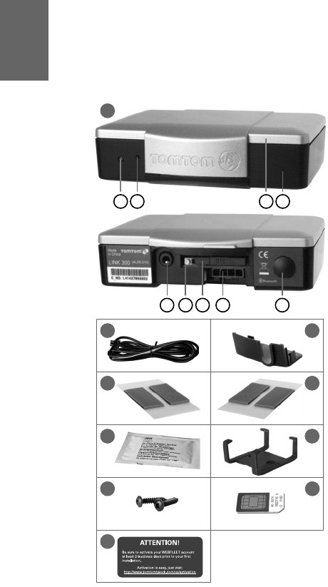
What’s in the box
4
EN
What’s in the
box aTomTom LINK 300
AService/Update cable connector
BRelease button for SIM card holder
CSIM card holder (SIM card installed)
DPower cable connector
EGPS antenna connector (SMB) for
optional use of an external GPS antenna
FLED
GReset button
HTop side
IBottom side
bPower cable
cPlastic seal
dTwo transparent adhesive strips for
windshield mounting
eTwo grey adhesive strips for dashboard
mounting
fCleaning tissue
gHolder
hTwo self-tapping screws and washers
iSIM card pre-installed
jActivation label
2
4
6
8
3
5
7
9
ABC D E
FG HI
10
1

EN
Before the Installation
5
Before the In-
stallation Congratulations
You have chosen TomTom LINK 300, a
Connected Navigation solution from TomTom
WORK. Connected Navigation enables you to
always stay connected to your people on the
road in a smart and easy way.
TomTom LINK 300 is a GPS receiver and GSM/
GPRS module in one unit, always providing
the vehicle’s current position. When used with
a TomTom navigation device, you will be able
to easily handle orders, as well as text and
status messages.
Attention! You must activate your TomTom
WEBFLEET account at least 2 business days prior to
installation. Your TomTom LINK 300 will not function
until this has been done. Activate at
www.tomtomwork.com/us/activation
What you need for the installation
Before starting the installation of your
TomTom LINK 3 00, read t h e safety notices a n d
warnings carefully and make sure you have
the following things:
•The TomTom WEBFLEET Contract
Confirmation letter including the
Activation Code.
• All parts mentioned in the chapter What’s
in the box on page 4 and two 2 A / fast
blow fuses (not included in the box).
•Placement outside with a clear view of the
sky, where you can get a strong satellite
signal for GPS reception.
•A TomTom navigation device compatible
to TomTom LINK 300 (for compatibility
information see leaflet).

EN
Safety first
6
Safety
first Important safety notices and warnings
Important: Read the following safety
instructions carefully
TomTom WORK accepts no liability for
damage that results from disregard for the
safety instructions.
This document is part of the product. Keep it in
a safe place. If you pass the unit on to a new
user, make sure you give them this document
as well.
•Important - damage caused through
improper installation
The installation and initial operation of the
unit must be performed by authorized
personnel only. In the event that users do
not install the TomTom LINK 300 per the
installation guidelines or if the device is
deployed improperly, i. e. powering the
device directly to a cigarette light adapter
all data charges associated with this misuse
will be the responsibility of the user.
•Caution - risk of injury in case of accidents
Do not mount the unit or accessories in the
inflation area of airbags or in the impact
area of the head or knees. Search carefully
for an installation location that will avoid
interference with displays, safety
equipment and controls.
•Caution - damage to the chassis
Make sure you do not drill into parts of the
chassis that have structural or security-
related functions. You cannot be certain
that they will function properly after
modification.
•Caution - risk of fire
Make sure you do not drill into covered
wiring harnesses, fuel lines or similar
components. Drilling into these can cause
fire.
•Caution - use of this product is restricted
in some areas
The GSM module of the TomTom LINK 300
is likely to interfere with electric devices
such as cardiac pacemakers, hearing aids,
electric devices used in intensive medicine,
and aviation equipment. The interference
with these devices can endanger the health
or life of the users. Do not use near
unprotected electrical units nor in areas
where the use of mobile telephones is
prohibited, such as hospitals and airplanes!
Switch off the unit if there is a danger of
interference with such equipment.

EN
Safety first
7
•Caution - danger of explosion
Parts of TomTom LINK 300 can cause
sparks, which can lead to explosions. This
may endanger human health and life. Do
not use the unit in areas with high risk of
explosion. When using TomTom LINK 300
follow the safety regulations per the US
National Electrical Code NFPA 70.
•Warning - repair and replacement
Repairs must be carried out by authorized
and qualified personnel only. Never replace
damaged parts of the unit yourself. Give
the defective unit to TomTom WORK. Only
the qualified staff of TomTom WORK are
authorized to repair or replace parts.
•Warning - damage to the device
Short-circuits inside the unit can be caused
by contact with water or other liquids. The
unit may be damaged by contact with
water. Use and store the unit in an area
protected from water.
•Caution - risk of accidents
Using the unit while driving is distracting
and can cause accidents. To ensure road
safety, only enter information in the unit
when the vehicle is not being driven.

EN
Proper Installation
8
Proper
Installa-
tion First you need to find the right place to install
your TomTom LINK 300. You can either decide
for a hidden or for a non-hidden installation.
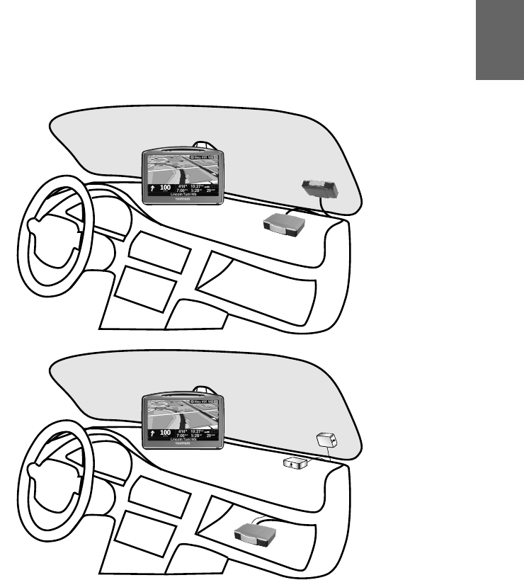
Non-hidden installation
If you do not want to use an external GPS
antenna and have free access to the device
you can simply affix it to the dashboard or to
the windshield of your vehicle. (see Mounting
the TomTom LINK 300 on page 13)
If the vehicle is often parked in direct sunlight
or is exposed to high outside temperatures for
long periods of time, the device may not work
properly. In those cases, TomTom WORK
recommends a hidden installation.
Hidden installation
If you prefer to keep the TomTom LINK 300 in
a hidden place, to protect it from high
temperatures or for safety reasons (to not
obstruct the driver’s view e.g. in the
windshield) you can place the device beneath
the dashboard e.g. in the glove compartment.
You will need to find a place where the top of
the device is not obstructed by metal items.
Also, you will need the external GPS antenna
(see Alternative Mounting on page 18). Use
only the external GPS antenna from TomTom
WORK. This is an optional accessory which is
not included in the box.
EN
Proper Installation
9
Non-hidden
Hidden
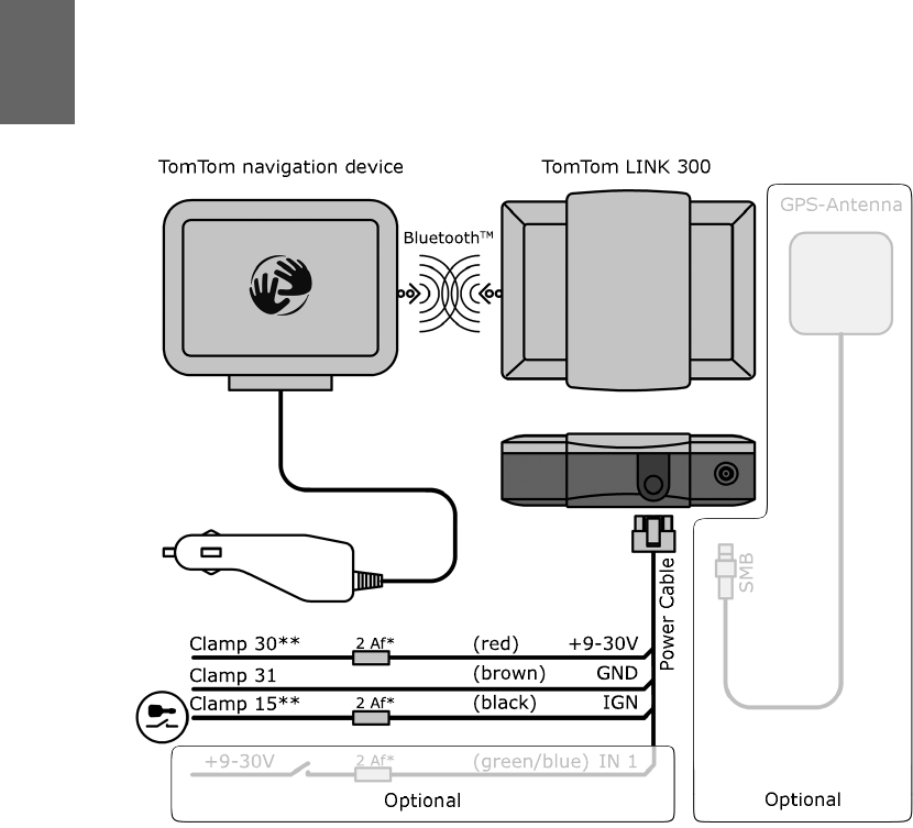
Connecting to power
11
EN
Connecting to
power
Connect TomTom LINK 300 to the vehicle
power supply with the standard vehicle
voltage (12 V / 24 V). Do not connect to a
voltage converter. The three wires GND, IGN
and PWR+ (supply voltage) must be
connected.
1. Connect the GND wire (brown) to ground
(clamp 31).
2. Fuse the PWR+ wire (red) and the IGN wire
(black) with one 2 A / fast blow fuse
(Technical data on page 24) each.
3. Connect the fused PWR+ wire (red) to the
carry current (clamp 30).
4. Then connect the fused IGN wire (black) to
ignition (clamp 15).
5. If you do not want to record digital inputs,
then connect the IN1 wire (green/blue) to
GND. If you want to record a digital input,
connect the IN1 wire (green/blue) to a 2 A /
fast blow fuse (Technical data on page 24),
then connect the fuse to a switch which is
connected to the power supply. For further
details see www.tomtomwork.com/in1.
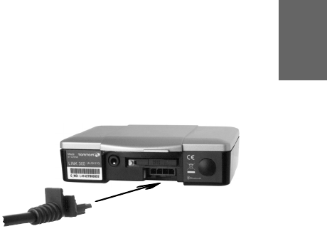
6. Insert the 4-pin plug into the power cable
connector.

EN
Testing operation
12
Testing
opera-
tion Power/Ignition test
Before testing the connection to power and to
ignition make sure you have carried out the
steps described in the previous chapters.
1. Please check all connections to the
TomTom LINK 300 (wires, fuses etc.).
2. Check that the SIM card is inserted
correctly.
3. Turn on the ignition. The LED must be on
with occasional (100ms) periods off.
4. Turn off the ignition - the LED must now be
off with occasional (100ms) periods on.
If the LED does not perform accordingly see
Diagnostics on page 21.
GPRS / GPS reception test
For this test, you may need to move the
vehicle to a location with a clear view of the
sky, to make sure that you have adequate GPS
and GPRS reception.
For this test put the TomTom LINK 300 into the
place where you want to affix it (please see
Mounting the TomTom LINK 300 on page 13).
1. Turn on the ignition.
2. Monitor the LED. It must be on with
occasional (100ms) periods off.
3. Please wait until the LED stops flashing.
If the LED keeps flashing longer than 10 min see
Diagnostics on page 21.
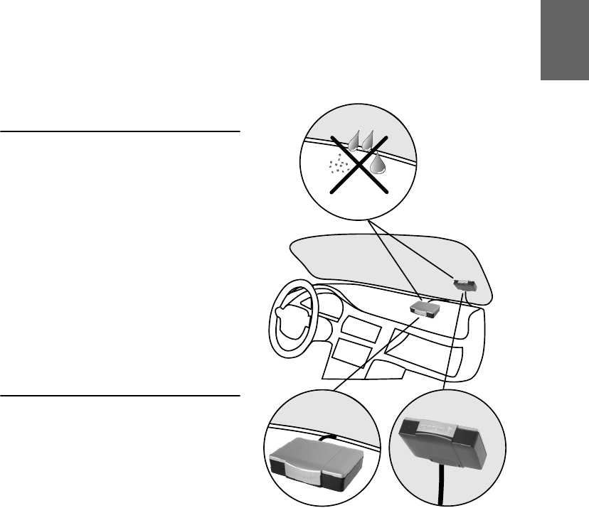
Mounting the TomTom LINK 300
13
EN
Mounting the
TomTom LINK
300
TomTom LINK 300 comes with an integrated
GSM antenna and an integrated GPS antenna.
• TomTom LINK 300 must be placed
unobstructed by metal objects and with the
top side having clear view of the sky.
• The device must not interfere with clear
vision for the driver.
• Tinted metallized windshields or those with
integrated filament heating may obstruct
the GPS reception.
• Place the unit on the dashboard or on the
windshield with min. 2 inches distance to
the vehicle chassis, so that optimal GSM
transmission and GPS reception is
ensured.
• The unit must be placed on an oil free, dry
and clean surface. Extreme temperature
changes/differences can affect the
adhesive property of the strips.
• Optimally find a place with a distance
bigger than 12 inch to the TomTom
navigation device.
The TomTom LINK 300 can be affixed to the
windshield or the dashboard with the two
adhesive strips. For information about a
hidden installation such as in the glove
compartment, see Alternative Mounting on
page 18.
Use the two adhesive strips to affix TomTom
LINK 300 to the dashboard (grey strips) or the
windshield (transparent strips). Follow the
safety instructions in this document.
OIL
OIL
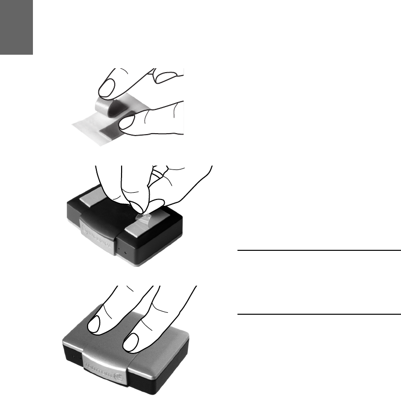
Mounting the TomTom LINK 300
14
EN
1. Choose a flat surface for accurate
positioning of the unit.
2. Clean the surface with the provided
cleaning tissue, so that the surface is oil
free, dry and clean.
3. Remove the protective film from one side
of the strips.
4. For dashboard mounting (see figure) stick
the strips to the bottom side. For
windshield mounting stick the strips to the
top side.
5. Remove the protective films from the other
side of both strips.
6. Place the unit with the adhesive strips on
the prepared surface. Press it gently for a
few seconds until it sticks.
Note: The full strength of the strips will be reached
after approx. 72 hours depending on the
temperature.
At 65F: 20min=65% / 1h=90%;
At 149F: 20min=90% / 1h=100%;
At 50F: 20min=20% / 1h=30%.
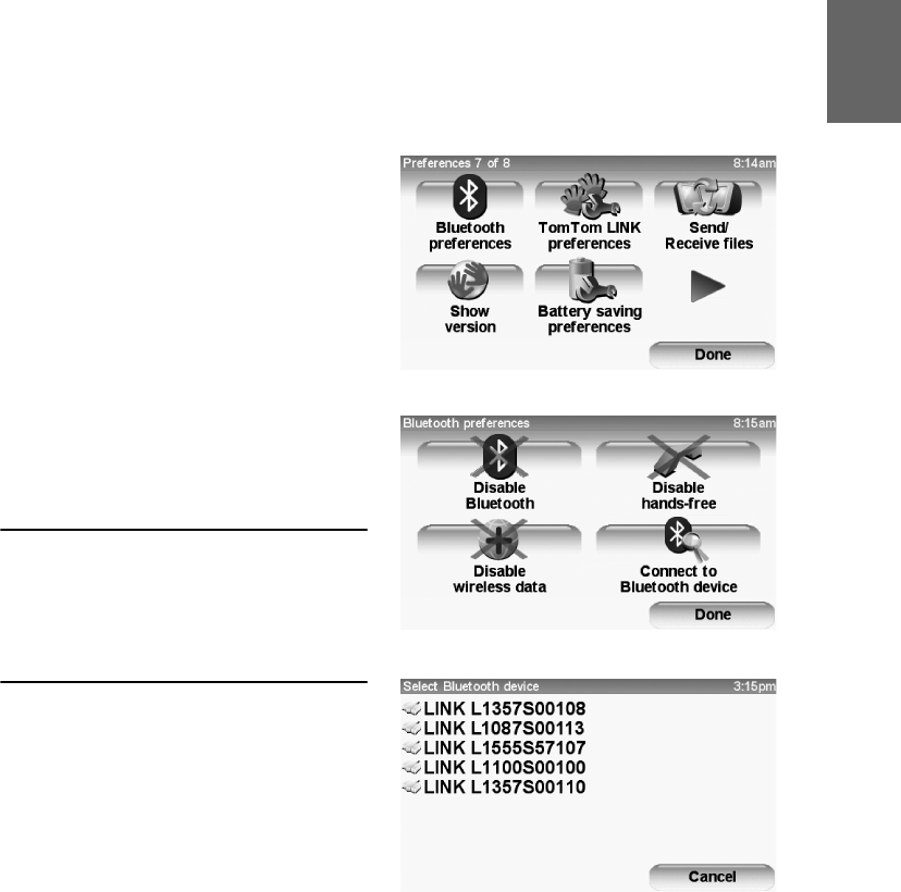
Connecting to navigation device & WEBFLEET
15
EN
Connecting to
navigation de-
vice & WEB-
FLEET
Connect your TomTom LINK 300 to your
TomTom navigation device to fully enjoy the
benefits of Connected Navigation.
1. Make sure that the TomTom LINK 300 is
connected to power and has GPRS
connection.
2. Switch on the navigation device.
3. Tap the screen to bring up the main menu.
4. Tap Change preferences.
5. Tap Bluetooth® preferences. If this menu
item is not displayed tap Show all menu
options first.
6. Tap Connect to Bluetooth® device.
The navigation device starts searching for
Bluetooth® devices:
If your navigation device finds more than one
Bluetooth® device, it shows you a list of the available
devices - please continue with step 7.
If your navigation device finds only one TomTom
LINK 300, continue with step 8.
7. Select your TomTom LINK 300 from the
list. The name starts with ’LINK’ followed
by the serial number of your TomTom LINK
300. The serial number is shown on the
outside of the box.
8. Enter the Activation Code indicated in your
TomTom WEBFLEET contract
confirmation.
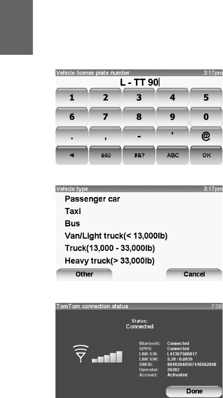
Connecting to navigation device & WEBFLEET
16
EN
9. Enter the identification information of the
vehicle correctly.
10.Select the appropriate vehicle type.
If you have properly connected the two
devices, the connection will be established
automatically. Additional menu items will
appear on your navigation device. On the
driving view of your navigation device the two
red crossed arrows must not be displayed.
You can always check the connection status
between the two devices by tapping
Connection status under TomTom LINK
preferences on your navigation device.
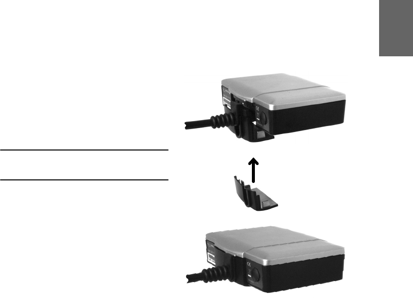
Closing the TomTom LINK 300
17
EN
Closing the
TomTom LINK
300
After you have successfully tested the
operation of the TomTom LINK 300 (see
Testing operation on page 12) and connected
it to the TomTom navigation device and
TomTom WEBFLEET (see Connecting to
navigation device & WEBFLEET on page 15),
you can now close the TomTom LINK 300 with
the plastic seal.
IMPORTANT: Once you have closed the TomTom
LINK 300 with the plastic seal, the device cannot be
opened again without damaging the seal.
For this, slide the plastic seal over the plug of
the power cable into the housing and press
gently until it engages.
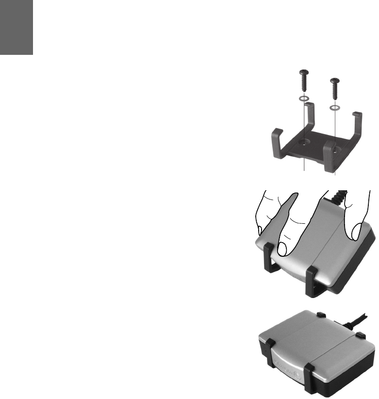
EN
Alternative Mounting
18
Alternati
ve
Mount-
ing Using the holder
You can also choose to mount the TomTom
LINK 300 using the holder. The holder can be
affixed either with the the two self-tapping
screws or with the adhesive strips. To use the
self-tapping screws, see the description
below. To use the adhesive strips please, see
Mounting the TomTom LINK 300 on page 13.
Follow the safety instructions in this
document.
1. Choose a flat surface for TomTom LINK
300.
Remember, when TomTom LINK 300 is in
the holder, it must have a clear view of the
sky.
2. Insert the two screws into the
corresponding holes in the holder.
3. Tighten the screws.
4. Carefully place the TomTom LINK 300 in
the holder until it clicks into place.

EN
Alternative Mounting
19
Mounting external GPS antenna
If you install the TomTom LINK 300 in a place
where it is not visible, so that it does not have
a clear view of the sky, you need to use the
TomTom WORK external GPS antenna
accessory (part number 9L09.001) which
comes with an integrated magnet and an
adhesive pad. The TomTom WORK external
GPS antenna is not part of the standard
TomTom LINK 300 product package.
Important!
• Only use the GPS antenna from TomTom
WORK, or the GPS performance will be
poor or will not work at all.
• Tinted windshields or those with integrated
filament heating may prevent good GPS
reception. In this case, place the GPS
antenna in the rear window or on the
outside of the vehicle.
• The magnet of the antenna will remain
attached to the outside of the car at speeds
of up to 108 M/h.
• Install the GPS antenna in a place where it
has a clear view of the sky and is
unobstructed by metal objects.
• The GPS antenna must be placed with the
adhesive pad on an oil free, dry and clean
surface.
•Extreme temperature changes / differences
can affect the adhesive property of the pad.
• To ensure proper GSM/GPRS reception
choose a place where the top side of the
TomTom LINK 300 is unobstructed by
metal objects.
EN
Alternative Mounting
20
1. Remove the rubber cap from the GPS
antenna connector.
2. Insert the plug of the GPS antenna into the
GPS antenna connector on the TomTom
LINK 300.
3. Prepare a smooth, clean, oil free and dry
surface in the windshield.
4. Attach the antenna to the prepared surface
so that the top side has clear view of the
sky. Either locate a smooth metal surface or
use the extra adhesive pad.
OIL
OIL

Diagnostics
21
EN
Diagnostics Monitoring operation
Monitor the operation of TomTom LINK 300 according to the table below.
Troubleshooting
Find solutions for malfunctions with the help of the LED and the table below.
LED mode
OFF Unit is in Standby mode
1sec on, 100ms off, 100ms on,
100ms off
Waiting for GPRS
1sec on, 100ms off Waiting for GPS
ON Normal operation (GPS and GPRS are available)
4sec off, 100ms on Ignition is off (unit is not yet in Standby mode)
Rapidly flashing: 500ms on,
500ms off
System error (see Reset TomTom LINK 300 on
page 23)
LED is active when ignition is
turned on and is off when ignition
is turned off
PWR+ wire is connected to ignition and the IGN wire
is connected to power (see Connecting to power on
page 11)
LED is off when ignition is either
turned on or off
Unit is not connected to the power supply (see
Connecting to power on page 11)
LED is neither constantly off nor off
with occasional periods (100ms) on
when ignition is turned off
IGN wire and the PWR+ wire are both connected to
power. (see Connecting to power on page 11)
LED shows that the device is
waiting for GPRS for longer than 10
minutes after turning on the
ignition
SIM Card may not be inserted correctly
GSM reception may be obstructed by metal objects
(see Mounting the TomTom LINK 300 on page 13)

Diagnostics
22
EN
Support
If you cannot find the answer to your question with the help of the tables above please contact
the TomTom WORK support team via the support form on our website
www.tomtomwork.com/us/company/support-contact.xml
LED is 1sec on, 100ms off for
longer than 10 minutes after
turning on the ignition
GPS reception may be obstructed, check whether you
have clear view of the sky
GPS antenna might not be connected properly (in
case of a hidden installation), check the connection to
the external GPS antenna and its position. It must be
the original TomTom WORK GPS antenna. (see
Alternative Mounting on page 18)
Reset TomTom LINK 300
23
EN
Reset TomTom
LINK 300
If the TomTom LINK 300 does not operate
properly or signals a system error (see
Diagnostics on page 21) you may need to
reset the unit. Only reset the TomTom LINK
300 after you have made sure you have carried
out all previously described steps without
success.
To reset the TomTom LINK 300 press the reset
button with a thin pointed object until it clicks
and keep it pressed for 5 seconds. The unit
reboots immediately after releasing the reset
button.

Technical data
24
EN
Technical data
Dimensions Body 3.3 x 2.6 x 0.9 in. / Holder 2.2 x 2.6 x 1.2 in
Weight Body: 3.4 oz / Holder: 0.4 oz
Material Body and holder: Injection molded plastic PC/ABS
Protection class IP 20
Supply voltage 12 V / 24 V (min. 9 V to max. 30 V)
Current
consumption
(average values)
At 14 V: typically < 50 mA
At 28 V: typically < 30 mA
Standby: typically < 1 mA
During data transmission
14V < 180mA
28V < 100mA
Fuse protection Operating voltage 9 - 30 V with 2 A / fast blow*
Ignition with 2 A / fast blow*
* Mini Fuse Fast-Acting 2A (Littlefuse Ord.No. 297 002) and
Mini Fuse Easy-Crimp In-Line Fuseholder (Littlefuse Ord.No. 153002)
Temperature -22°F to +158°F operation (for GSM module operation: Temperatures outside the
range -4°F to +67°F might slightly deviate from ETSI specifications.)
-40°F to 176°F storage
GSM Integrated GSM antenna and GSM module
Quadband GSM 850 / 900 / 1800 / 1900
GPS Integrated GPS antenna and GPS receiver
BluetoothTM Integrated BluetoothTM (class 2) for connection to TomTom navigation device
Ignition input To be connected to the ignition clamp to switch on/off device together with
ignition
Digital input 1 input switchable to supply voltage
GPS antenna
connector for
external GPS
antenna
(optional accessory)
SMB (male) - (antenna - female)
Supply voltage range 3 V to 5 V
Minimum antenna gain at 3 V: 20 dB
Maximum antenna gain: 40 dB
Maximum noise rating: 1.5 dB
Addendum
69
Ad-
den
du
m
Federal Communications Commission (FCC)
Statement
FCC ID: S4LLINK3002
You are cautioned that changes or modifications not
expressly approved by the part responsible for compliance
could void the user’s authority to operate the equipment.
This equipment has been tested and found to comply with the
limits for a Class B digital device, pursuant to part 15 of the
FCC rules. These limits are designed to provide reasonable
protection against harmful interference in a residential
installation. This equipment generates, uses and can radiate
radio frequency energy and, if not installed and used in
accordance with the instructions, may cause harmful
interference to radio communications. However, there is no
guarantee that interference will not occur in a particular
installation. If this equipment does cause harmful interference
to radio or television reception, which can be determined by
turning the equipment off and on, the user is encouraged to
try to correct the interference by one or more of the following
measures:
• Reorient or relocate the receiving antenna.
• Increase the separation between the equipment and
receiver.
• Connect the equipment into an outlet on a circuit different
from that to which the receiver is connected.
• Consult the dealer or an experienced radio/TV technician
for help.
Operation is subject to the following two conditions:
(1) this device may not cause interference and
(2) this device must accept any interference, including
interference that may cause undesired operation of the
device.
FCC RF Radiation Exposure Statement:
(1) This Transmitter must not be co-located or operating in
conjunction with any other antenna or transmitter.
(2) This equipment complies with FCC RF radiation exposure
limits set forth for an uncontrolled environment. This
equipment should be installed and operated with a minimum
distance of 20 centimeters between the radiator and your
body.
IC Declaration of Conformity
IC: 5767A-LINK3002
Operation is subject to the following two conditions:
(1) this device may not cause interference and
(2) this device must accept any interference, including
interference that may cause undesired operation of the
device.
This Category II radiocommunication device complies with
Industry Canada Standard RSS-310.
Ce dispositif de radiocommunication de catégorie II respecte
la norme CNR-310 d’Industrie Canada.
This Class B digital apparatus complies with Canadian ICES-
003.
Cet appareil numérique de la classe B est conforme à la norme
NMB-003 du Canada.
Responsible party in North America
TomTom, Inc., 150 Baker Avenue, Concord, MA 01742, Tel:
866 459 3499
Limited Warranty
© 2008 TomTom International BV, The Netherlands. Our
limited warranty applies to this product. You can review this
limited warranty at http://www.tomtomwork.com/us/
company/termsconditions.xml.