Tong Lung Metal Industry PT2C ELECTRONIC LEVERSET User Manual
Tong Lung Metal Industry Co.,Ltd. ELECTRONIC LEVERSET
User Manual
CARD
CARD
card
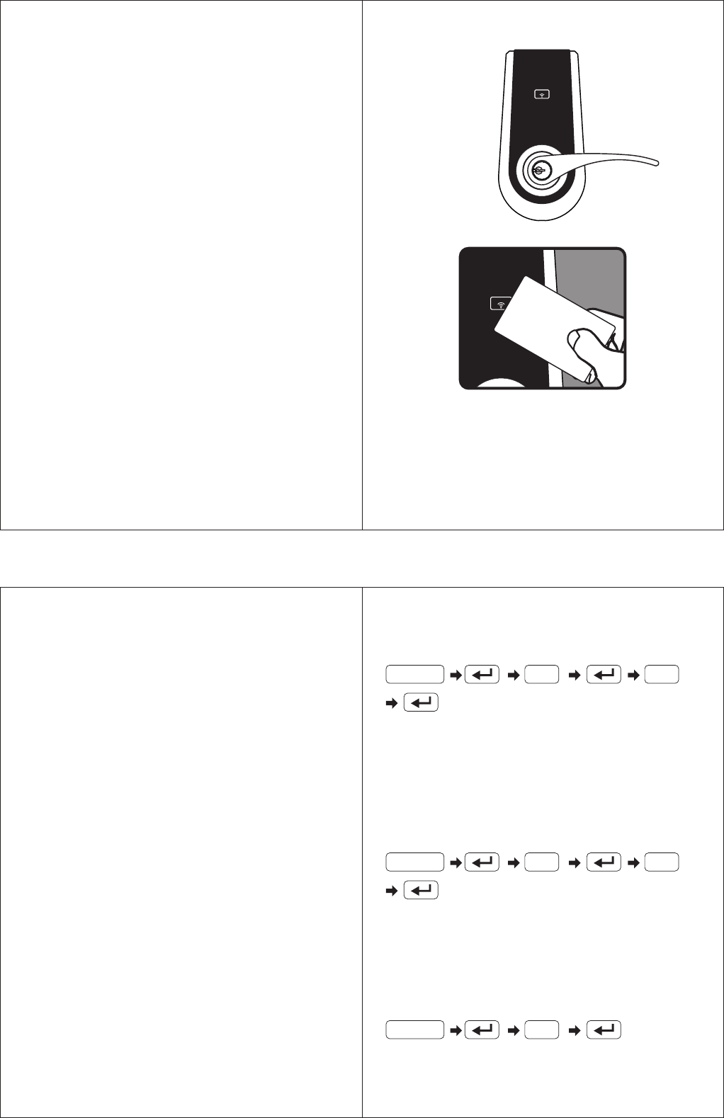
Instruction : After the setup is complete, place the card close
to the sensor (when it beeps once, the registration is complete).
The number “1” above represents the order of the card.
If the card to be registered is the third card, enter the number
“3”, and so on. A maximum of 6 cards can be registered.
They can be registered individually or consecutively.
13 1
2. Voiding designated cards
Instruction : The number “1” above represents the order of
the card. To void the cards, please enter the order of the card.
For example, if the third card is to be voided, enter “3”, and
so on. The cards may be voided individually or consecutively.
3. Voiding all cards at the same time
14 1
15
Instruction : When it beeps twice, all cards have been voided.
SETUP
1. Register the card
1-1 All cards have been registered in the factory.
1-2 The master password must be entered for the registration.
The cards may be registered individually or consecutively
with a maximum of 6 cards.
2. Void designated card
2-1 The master password is required to void the card.
Voided cards may be reused again after registration.
2-2 The cards may be voided individually or consecutively.
3. Void all cards at the same time
3-1 The master password is required to void the cards.
3-2 All cards may be voided at the same time. The voided
cards may be reuse again after registration.
ELECTRONIC KEYPAD LOCK
INSTRUCTION MANUAL
FOR PROXIMITY CARD
Notice : The changes or modifications not expressly
approved by the party responsible for compliance could
void the user's authority to operate the equipment.
IMPORTANT NOTE : To comply with the FCC RF exposure
compliance requirements, no change to the antenna or
the device is permitted.
Any change to the antenna or the device could result
in the device exceeding the RF exposure requirements
and void user's authority to operate the device.
This device complies with Part 15 of the FCC Rules.
Operation is subject to the following two conditions :
(1) this device may not cause harmful interference, and
(2) this device must accept any interference received,
including interference that may cause undesired
operation.
REGISTRATION
1. Registering the cards
Enter PC
Enter PC
Enter PC
45 40 35
1-3/4" 1-9/16" 1-3/8" 2"
51
120x165(mm)
Product :
Purchase Date :
DIGITAL TOUCHPAD LEVER LOCK
Limited Warranty Statements
1. Warranty
The manufacturer warrants the Product to be free
from defects in material and workmanship for a period of 12 months
from the original date of purchase.
If you discover a defect in the Product covered by this warranty, we will repair or
replace the item at our option using new or refurbished components.
2. Exclusions
This warranty covers defects in manufacturing discovered while using the
Products as recommended by The manufacturer rather than occurred by the act
of God, and damages caused by misuse, abuse, and unauthorized modification.
3. Limited of Liability
The manufacturer will not be held liable for incidental or consequential losses or
damages to any act of God.
4. Reminder
Service requirement shall subject to the presentation of this warranty card
and defective parts to the manufacturer.
The warranty card will not be reissued if lost.
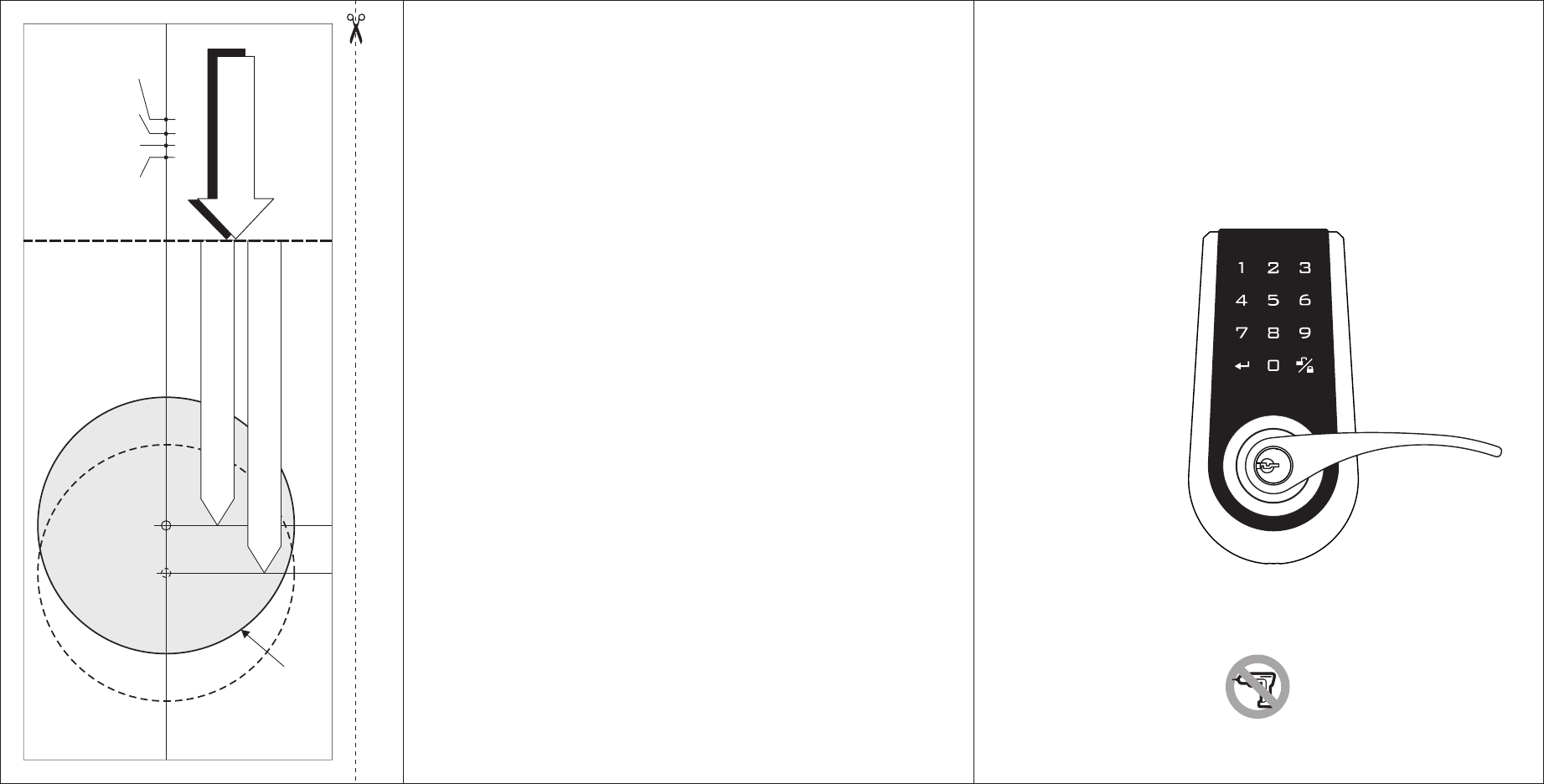
TEMPLATE
Mark Ø1" (25.4mm) hole at
center of door edge.
Ø ( )2-1/8" 54mm
Fit here on door edge
FOR ( ) 2-3/4” 70mm BACKSET
FOR ( ) 2-3/8” 60mm BACKSET
USER MANUAL
Attention : Please do not use the "electronic" screwdriver for installation.
ELECTRONIC
KEYPAD LOCK
This device complies with Part 15 of the FCC Rules.
Operation is subject to the following two conditions :
(1) this device may not cause harmful interference, and
(2) this device must accept any interference received, including interference
that may cause undesired operation.

■
˙
˙
˙
■
■
■
˙
˙
˙
˙
˙
˙
˙
˙
˙
˙
˙
˙
˙
˙
˙
˙
■
■
■
■
Installation Instructions ..................................P.1
Replace the old lock with the new one
Install the new lock on the new door
Starting the installation ..................................P.4
Operation Interface .........................................P.7
Specifications and Functions ........................P.8
Code Setup .....................................................P.11
Notifications ...................................................P.11
Function Setup ..............................................P.12
Troubleshooting ............................................P.14
Indentifying the door handing
Power supply
Low battery indication
Keypad light indication
Audio indication
Programming Code (PC)
User Code (UC)
Delete individual user code
Delete all user codes at once
Invalidate user codes temporarily
Create the one-time user code
Restore default PC & UC
Unlock
Lock
Automatic lock
Password protection function
Backlit function
Table of Contents
P.1
P.1
P.2
P.8
P.8
P.8
P.8
P.8
P.9
P.9
P.9
P.9
P.9
P.9
P.10
P.10
P.10
P.10
P.10
1
2
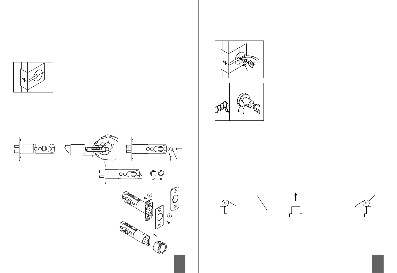
The distance between the edge of the door to the center of
the hole is the latch backset. The adjustable latch provides
two choices of backsets 2-3/8" (60mm) and 2-3/4" (70mm).
Change the backset for the latch according to the illustration.
For adjustments please refer to the following illustrations.
Note : The correct direction for the
cam is shown as the circle on
the left side.
ac
b
Latch face plate
Prior to installation, please make sure that the face
plate is appropriate for the latch.
Drive-in latch
Installation of the round face plate
Replace the old lock with the new one
To replace the old lock with this product on the same door, please confirm the
backset for the latch and the specifications for the face plate match. Please also
refer to the following instructions to adjust the backset and face plate to match the
existing door's specifications.
Install new lock on the new door
To install this product on a new door, please go through the
following steps to drill the hole.
Check that the lever direction meets the door handing. If not, please switch the
levers by following steps.
■Installation Instructions
a. The illustration shows a backset of ( ).
b. Pull the cam all the way to the right, to adjust backset to 2-3/4" (70mm).
c. To restore back to 2-3/8" (60mm), push the adjustable sleeve all the way to
the left.
2-3/8" 60mm
Replace the face plate
1. Use the slotted screwdriver to pry open the
face plate and the lock body.
2. Install the appropriate face plate onto the latch
body.
Align the round face plate to the head of the latch,
and lock it into position.
Mark The Door With Template
Select the height and backset as desired on the door
face ; use the TEMPLATE as an indication to mark the
center of the circle on the door face and the center of
the door edge.
Drill Holes
Using the marks as a guide to drill a hole Ø2-1/8"
(54mm) through the door face for the lockset, then
a hole of Ø1" (25.4mm) for latch.
Identify Door Handing
Face the door from outside, the door is left handed if the hinge is on the left-hand
side of the door, whereas the door is right handed if the hinge is on the right-hand
side of the door.
Interior
Exterior
Door Hinge
(Left Handed) (Right Handed)
Before installing this product, please confirm the door opening
direction to make sure that the lever is installed in the correct
direction.
3
c
a
b
4
a b c
a b c d
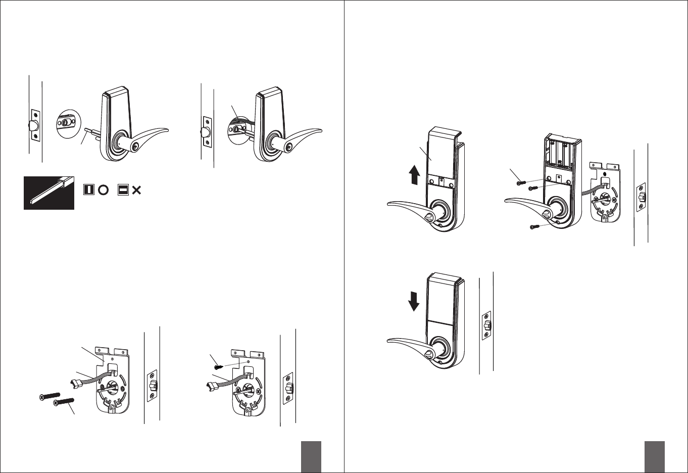
■Start the installation
1. Install latch
a. Insert the latch and lay the faceplate against the door edge.
Use a pencil to mark its perimeter, then take out the latch.
b. Chisel out the portion you've marked with pencil for about 5/32" (4mm) deep.
Score the area within the borders as clearly and precisely as possible.
Ensure the plate can fit flush with the door edge surface.
c. Insert the latch and tighten it with screws.
Be sure the holes for through-bolts (next to the adjustable cam) are horizontally
aligned.
d. It is not necessary to chisel the door edge for the faceplate installation if you use
the drive-in latch.
You may install it into the edge bore directly, but be sure the bevel should face
the outside assembly.
a. Half-close the door to lay the latchbolt against the door frame.
Mark the position of faceplate as an indication.
Place the strike against the door frame and mark its perimeter.
Make sure the center of strike is perfectly aligned with the center of faceplate.
b. Drill a ø1" (25.4mm) hole with 1/2" (13mm) depth on the center of strike outline.
Then use the chisel to scrape out the door frame for 1/16" (1.6mm) deep within
the traced outline.
Make sure to chisel deep enough to allow the strike to lay flush with the frame
surface.
c. Insert the strike and tighten it with screws.
Note : please use “tapping screws” for a metal door.
2. Install strike
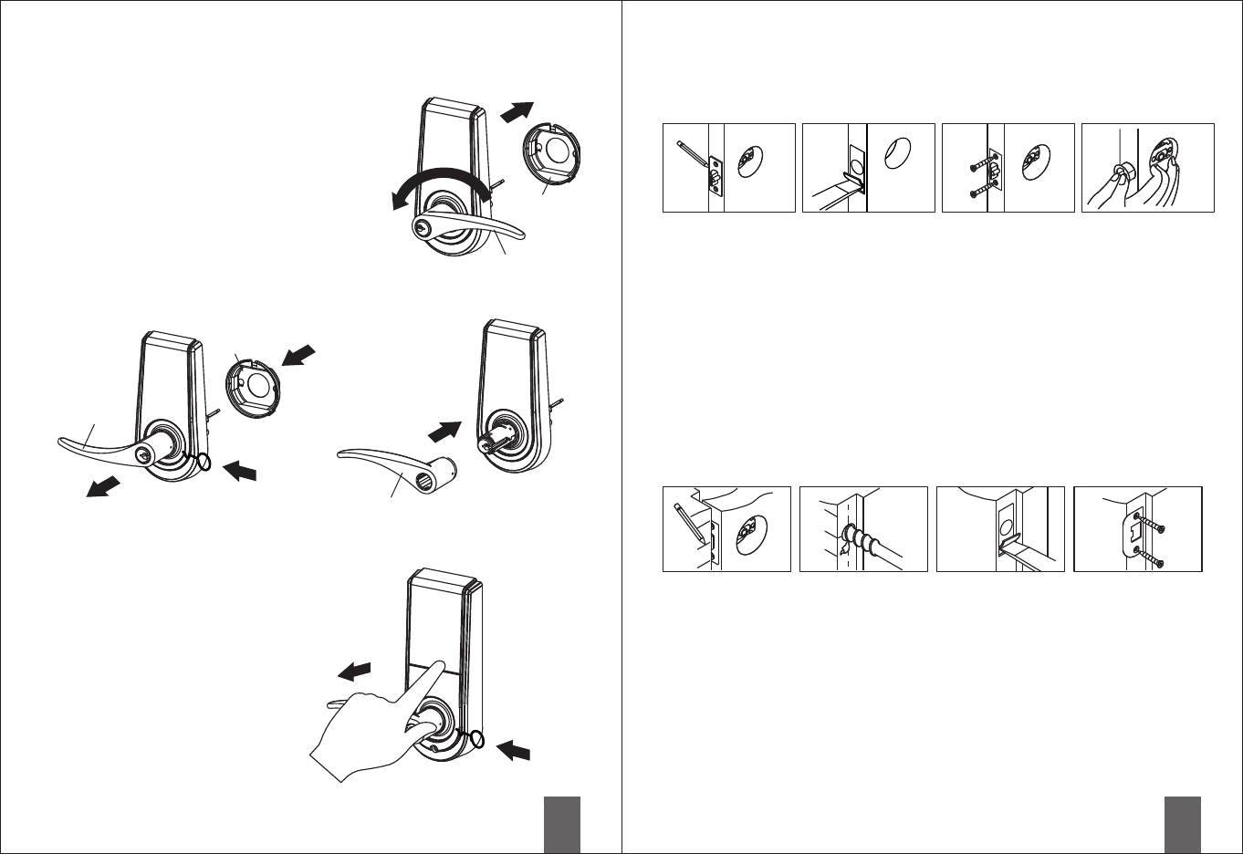
Change Lever Handing
a. Make sure that the lock is unlocked.
(The spindle is perpendicular.) Remove the
protection sleeve of the exterior lock unit.
Rotate the exterior lever by 180 degrees and
return the protection sleeve to its original position.
b. Insert the dismantle tool into the hole on the
neck of the exterior lever and press down,
and pull the lever out at the same time. From the
interior, just remove the lever and switch the
interior and exterior levers.
c. Push in and fasten the lever. Make sure that the
lever is correctly in place, and test the lock by
turning it to make sure it's functioning properly.
Protection
sleeve
Protection
sleeve
Exterior lever
Exterior lever
Interior lever
Remove the interior lever
Use the thumb and index finger to push against the
lock body while holding and pulling the lever back.
Meanwhile, insert the dismantle tool into the hole
on the side of the lever, press down, and the
lever can be pulled out.
5
a b
6
b
c
a
3. Install the exterior lock body
a. Fit the spindle through the square cam of the latch.
b. Fit the cable through the cross bore above the latch.
vertically
Spindle
Cable
The spindle must be vertical.
4. Install the interior mounting plate
a. Pass the cable through the cable hole on top of the interior plate. Then fasten the
interior plate with screws.
b. Examine whether the exterior lock unit and the interior plate are tilted. If so,
please loosen the screws for adjustment, and re-fasten the screws.
c. Wood screws or self-tapping screws may be used if needed.
(Wood screws are used for wooden doors, and self-tapping screws are used for
metal doors to increase bonding.)
Interior plate
Cable Cable
Fasten screws
Wood screws or
self-tapping
screws
5. Install the interior lock body
a. Push the battery cover upward.
c. Install 4 AA Alkaline batteries and close the battery cover. Installation is complete.
b. Connect the interior and exterior cables. Align the interior lock unit to the spindle
and push it in (the turn-piece is horizontal). When the interior lock unit is flush
with the door, fasten with screws.
If the interior lock body cannot be flush with the door, please push the cable into
the cross bore.
Installation
screws
Battery
cover
7
8
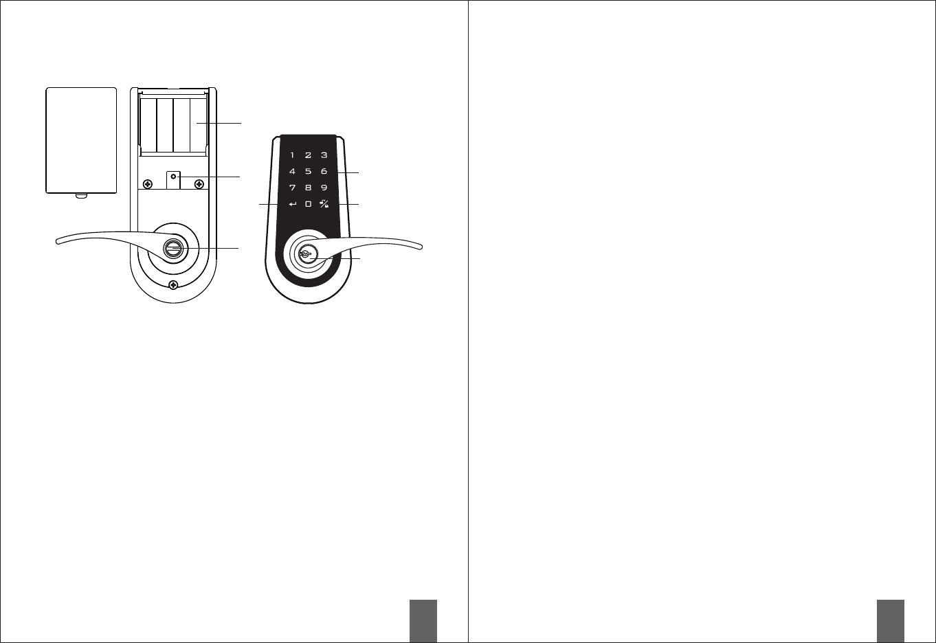
Confirm button
For function setup.
Number buttons
To enter user codes. Each code
must be 4-10 digits long.
To be locked and unlocked with
the key.
Battery cover
Push it upward and outward to
replace the batteries.
Cylinder
Uses 4 AA Alkaline batteries.
Indication light
When the light is lit continuously, it
means the unit is in operation.
When it's blinking, it means low
battery and the batteries need to
be replaced.
Lock and unlock from the interior.
Lock/unlock button
Lock and unlock from the exterior.
Battery holder
Turn-piece
■Specifications and Functions
1. Power supply
If the password is entered incorrectly more than 5 times, the system will initiate its
protective mode and stop functioning.
5. Programming Code (PC)
-1 The default programming code is “0000”. It is recommended that the user
change the programming code during initial installation.
5-2 There is only one programming code and is
5-3 The programming code cannot be used to unlock the door.
5-4 The programming code
5-5 The programming code can be changed anytime as needed.
DC6V, 4 AA, 1.5V Alkaline batteries. (not included)
2. Low battery indication
2-1 During operation, if the red light on the battery cover blinks and 10 short beeps
are heard, it means that the battery is low. The batteries need to be replaced
immediately.
2-2 All settings will remain active and won't change or disappear even if the
battery is down.
2-3 When the batteries are fully drained, the system can still be locked or unlocked
manually with the key.
3. Keypad light indication
4. Audio indication
4-1 1 short beep means the operation is normal.
4-2 2 long beeps mean the setting is correct.
4-3 3 short beeps mean operational error.
4-4 3 long beeps mean the default password has been restored.
4-5 5 short beeps mean password operational error. The system will initiate the
protective mode and stop functioning.
4-6 10 short beeps mean the battery is low.
5
used to set all functions.
must be 4-10 digits in length.
■Operational interface

9
10
6. User Code (UC)
6-1 The default user code is “1234”. During initial installation, delete the default user
code, and then set the new user code.
6-2 A total of 6 user codes can be saved.
6-3 The user code can only be used to unlock the door and
6-4 The user code
6-5 The user code can be deleted or added at anytime as needed.
7-1 The same user code can be reset after being
deleted.
7-2 The programming code is needed to delete
8. Delete all user codes
8-1 The original user codes can be reset again.
8-2 After deleting all user codes, the automatic lock and the button lockup
functions set previously will automatically be disabled. The
user code
8-3 The programming code is required to delete
9. Temporarily user code
9-1 This will temporarily disable all user codes. The automatic lockup and keypad
lockup functions that were set previously will automatically be disabled. A key
must be used to lock and unlock the door.
9-2 To restore the code function and other electronic functions, repeat the steps for
“Temporarily user code”.
10. one-time user code
10-1 After the one-time user code is entered and used, it is and won't be
able to open the door again.
10-2 The same one-time user code can be set repeatedly.
10-3 The programming code is needed
to set other functions.
must be 4-10 digits in length.
User codes can be deleted individually.
individual codes.
All user codes can be deleted at once.
door can only be locked
or unlocked with a key. The original functions will be restored once the
is set.
all user codes.
disable
disable
Create
disabled
for setup.
7. Delete individual user code
11. Restore the default PC & UC
to delete
12. Unlock
a registered
12-2 To unlock with the keypad
1. Place the hand within 2 cm of the keypad or press any key once to light up the
keypad.
2. 4 numbers will appear on the keypad. Press them in any order.
3. Enter the user code.
13. Lock
The door can be locked from
the inside
14. Automatic lockup
14-1 The timer (10-99 seconds) of automatic lockup can be set up by the user as
needed. (The default timer is 30 seconds after the system is unlocked.)
14-2 To disable the automatic lockup, please repeat the steps for “Automatic lockup”.
15. Code protection
If the user code is entered incorrectly over 5 times, the system will initiate the
protective function and disable the keypad for 45 seconds.
16. Backlight
When the hand is within 2 cm of the keypad, the backlight will light up for about 5
seconds, making it easy to operate lockset in the dark.
Use this function when forgetting the programming code or all settings.
12-1 The door can be unlocked by entering user code or the key from
outside, or pressing the lever down / turning the knob from inside.
4. Press the button.
When the light for the key goes out, the system is unlocked.
When the keypad lights up, the user may press the keypad, press button or use
the key and automatic lockup function to lock the door.
by turning the interior turn-piece.
11
12
■Code setup
All setup should be done when the system is unlocked.
Turn keypack backlight on by approaching your hand or
pressing a button, then proceed with setup.
1. During initial installation, it is recommended to change the default
programming code (0000), delete the default user code (1234), and add
the new personal user code prior to setting up other functions.
2. Two long beeps indicate that the input is correct.
When the keypad blinks three times with three short beeps, the input is
incorrect.
3. During the function setup, if it takes longer than 6 seconds to finish any
step, the system will automatically leave the program.
4. This product can be operated with the keypad or key.
5. Please refer to the instructions for function setup.
■Notification
1. Alkaline batteries are recommended to maintain stable and prolonged
power.
2. Do not mix the alkaline batteries with regular zinc-carbon batteries
and avoid mixing batteries of different brands.
3. Do not use any chemicals or add any lubricants when cleaning the lock, to
avoid damaging the panel and coating.
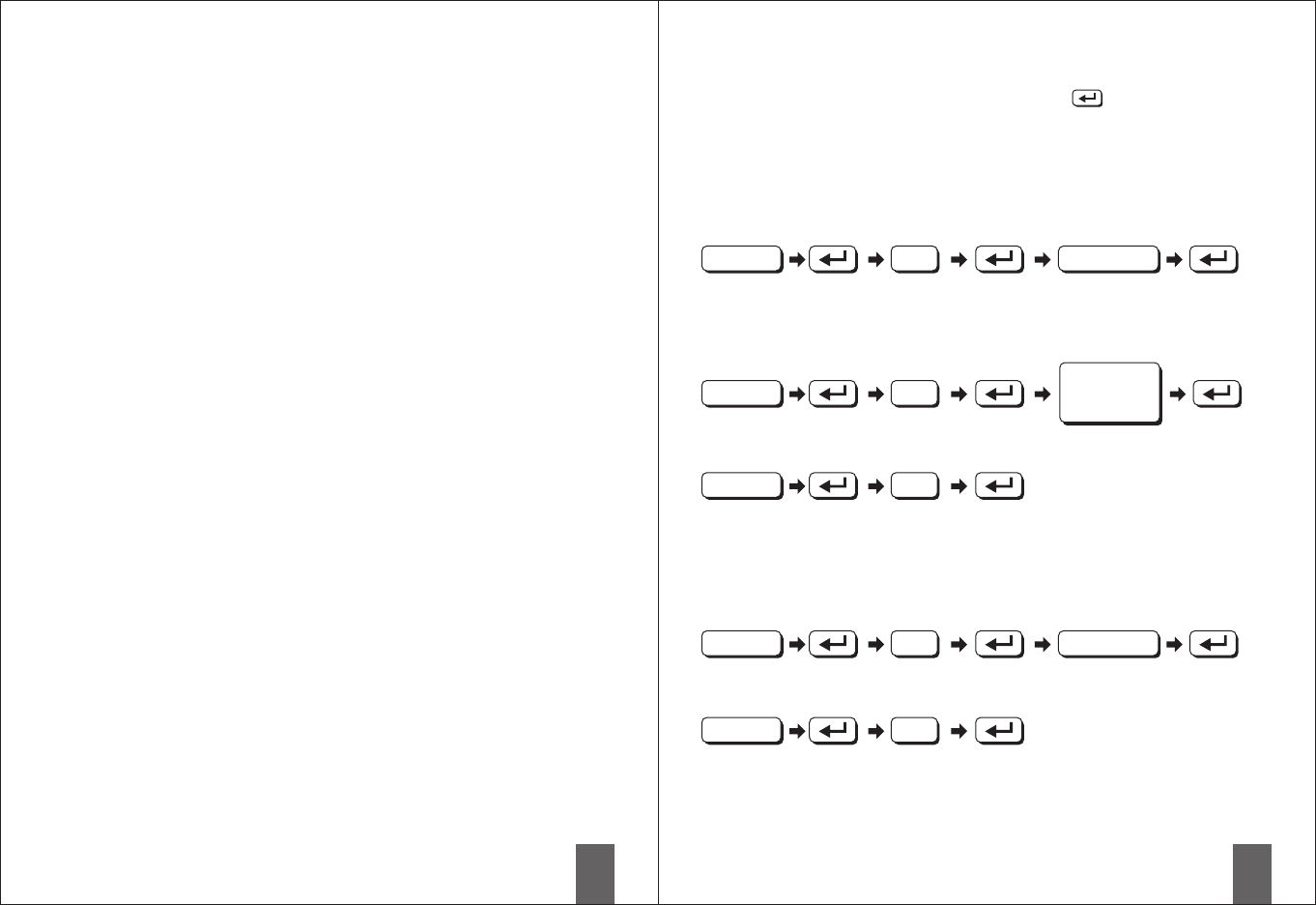
■Function setup
Add new user code
Instruction : A total of 6 user codes with a combination of 4 to 10 digits can be
set up.
Delete individual user code
The UC to
be deleted
Delete all user codes
Instruction : When all user codes are deleted and no new user code is set up, all
electronic lockup functions will be disabled. (The electronic functions
will be restored when a new user code is set.) During this time, the
door must be locked or unlocked manually with a key.
Change programming code
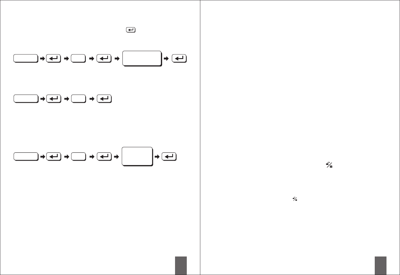
Automatic lockup
Instruction : The default setup for the automatic lockup timer is 30 seconds.
To modify the timer for the automatic lockup, please refer to the
instructions for “Automatic lockup timer”. To cancel the automatic
lockup, please repeat the setup procedure for “Automatic lockup”.
Enter PC New UC
1
2
3
4
5
■
■
PC (Programming code)
UC (User code)
Confirm button
Enter PC
Enter PC
Enter PC
Enter PC
New PC
13
14
■Troubleshooting
Scenario 1
After the installation is complete and the batteries are in
place, none of the buttons are responsive.
(No sound, and no backlight)
Cause : Issues with batteries or the wiring.
Solution : Replace the batteries or make sure the batteries are installed
correctly. Please check whether the cable from the interior lock
unit is connected correctly.
Scenario 2
the programming code while
, the error message after pressing the
confirm button.
(The light blinks three times with three short beeps.)
Cause : Function setup locked.
Solution : Unlock the door by turning the turn-piece from the interior lock
unit or with a key from the exterior.
When entering setup of other
functions appears
with the door
Temporarily user codesdisable
Use one-time user code
Instruction : When all user codes are temporarily all electronic functions will
be temporarily as well. The door must be locked or unlocked
manually with the key. To restore user code functions, please
repeat the setup process for “Temporarily user code”.
disabled,
disabled
disable
Enter
new UC
Restore factory default
Instruction : After removing the batteries, touch the keypads for three seconds and
re-install the batteries.
When the numbers 2, 5, 8, 0 are displayed on the keypad, press the
four numbers in any order until all numbers disappear.
8
9
Instruction : the timer can be set from 10 to 99 seconds.
Automatic lockup timer
6
Scenario 3
The door will not lock after pressing the button because
the lever was turned before the motor had finished operating.
Cause : The lever or the knob is turned too early while the motor is not yet
operating.
Solution : Wait for the end of the motor operating sound(the keypad light is
off), and then press the button again to execute the lockup
function.
■
■
PC (Programming code)
UC (User code)
Confirm button
Enter PC
Enter PC
Enter PC
Enter a two-digit
number (10~99)
Instruction : Once this user code is entered and used, it and unable
to open the door again. However, the same one-time user code can
be set again.
is disabled