Top Victory Electronics 92P2-FBT LCD TV User Manual
Top Victory Electronics (Taiwan) Co Ltd LCD TV
UserManual.wiki
>
Top Victory Electronics
>
92P2-FBT User Manual
>
User Manual Part 2
Contents
1.
User Manual Part 1
2.
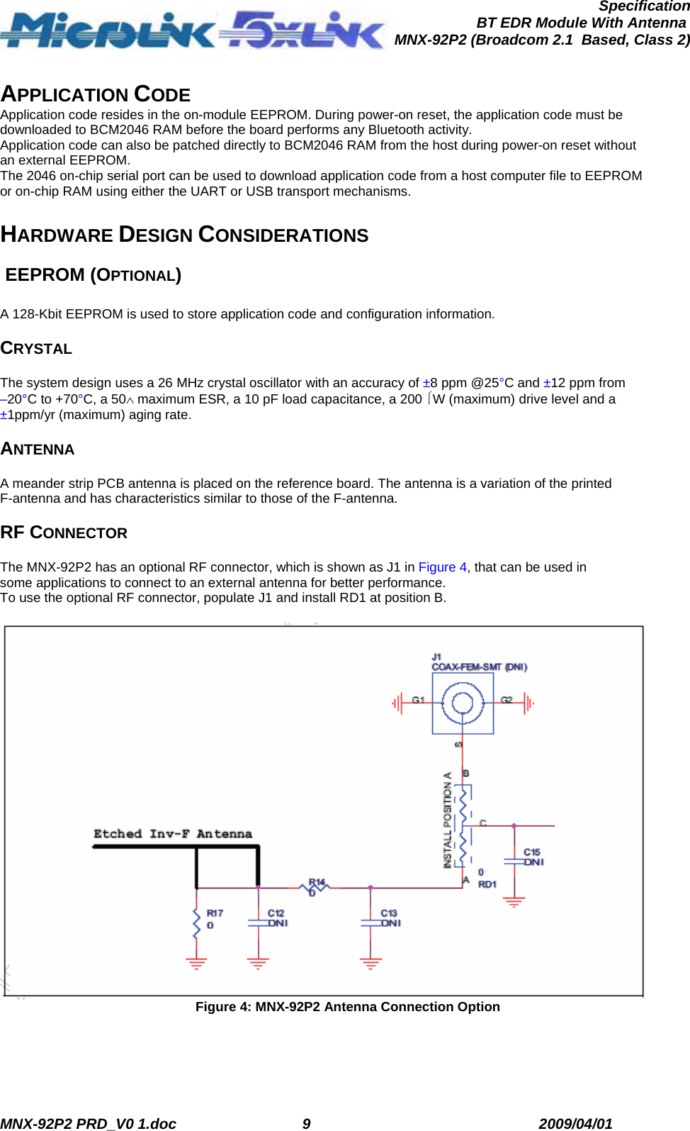
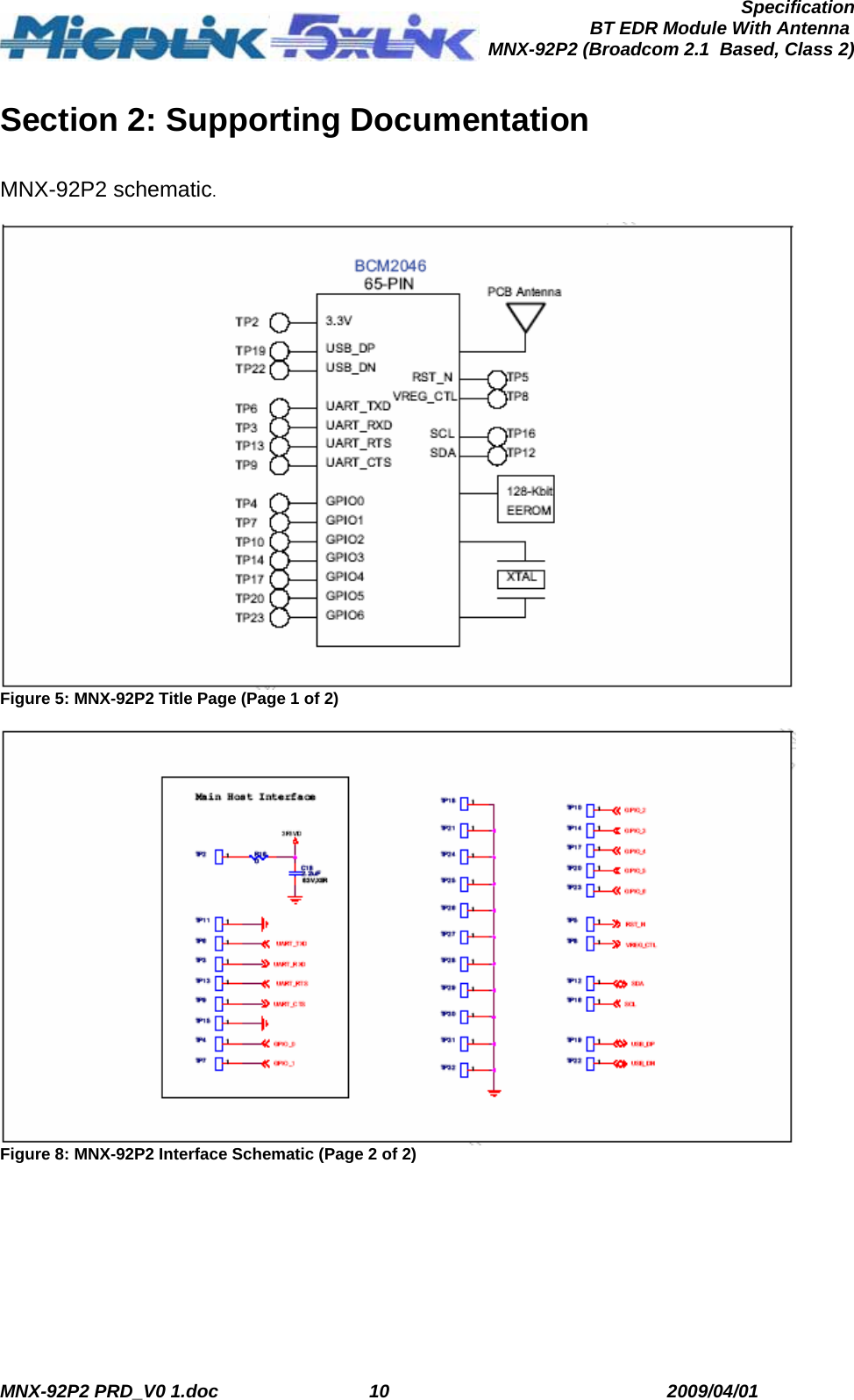
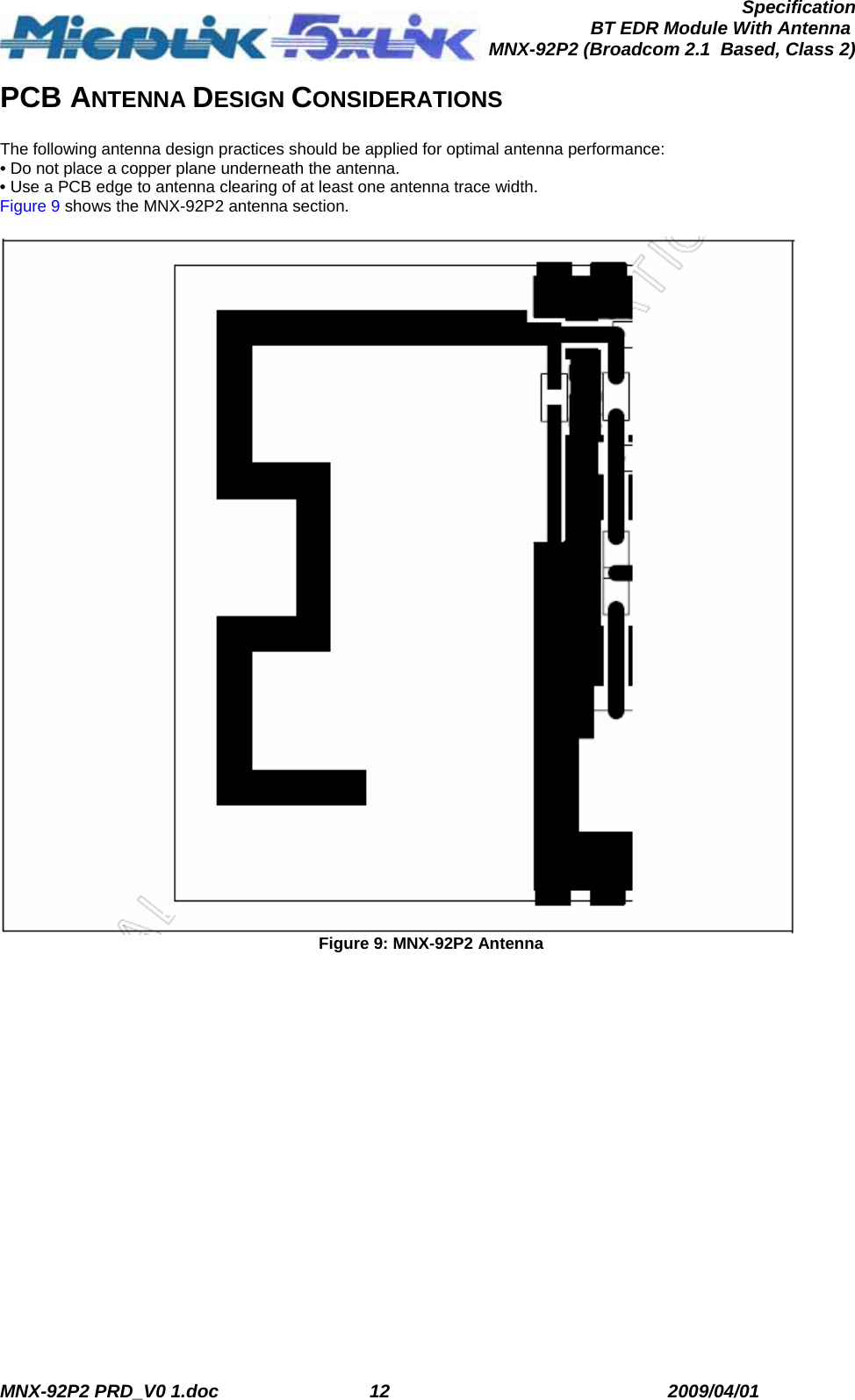
User Manual Part 2
User Manual Part 2
Navigation menu
Upload a User Manual
Namespaces
Wiki Guide
HTML
PDF
Info
Views
User Manual
Discussion / Help
Navigation