Top Victory Electronics 92P2-FBT LCD TV User Manual
Top Victory Electronics (Taiwan) Co Ltd LCD TV
Contents
- 1. User Manual Part 1
- 2. User Manual Part 2
User Manual Part 2
MNX-92P2 PRD_V0 1.doc 1 2009/04/01
Specification
BT EDR Module With Antenna
MNX-92P2 (Broadcom 2.1 Based, Class 2)
Specification
MNX-92P2
Bluetooth
Embedded Module
With Antenna
(Broadcom Based, Class 2)

MNX-92P2 PRD_V0 1.doc 2 2009/04/01
Specification
BT EDR Module With Antenna
MNX-92P2 (Broadcom 2.1 Based, Class 2)
Revision History
Rev. Date Author Reason for Changes
0.1 Apr.1, 2009 Jester Lee z First release

MNX-92P2 PRD_V0 1.doc 3 2009/04/01
Specification
BT EDR Module With Antenna
MNX-92P2 (Broadcom 2.1 Based, Class 2)
Table of Content
Section 1: Overview........................................................................................................................................4
Features ..................................................................................................................................................4
SUMMARY OF BENEFITS......................................................................................................................4
FUNCTIONAL DESCRIPTION ................................................................................................................6
PHYSICAL DESCRIPTION .....................................................................................................................7
Section 2: Supporting Documentation.....................................................................................................10

MNX-92P2 PRD_V0 1.doc 4 2009/04/01
Specification
BT EDR Module With Antenna
MNX-92P2 (Broadcom 2.1 Based, Class 2)
Section 1: Overview
INTRODUCTION
The MNX-92P2 is a Bluetooth® embedded module based on the BCM2046 Bluetooth 2.1
specification-compliant stand-alone baseband processor with an integrated 2.4 GHz transceiver. It is fully
compliant with the Bluetooth radio specification and incorporates new modulation schemes to support
enhanced data rates (EDRs) of 2 Mbps and 3 Mbps. The MNX-92P2 module supports both UART
and Universal Serial Bus (USB) version 2.0 full-speed interfaces, and is fully compatible with the HCI interface
specification. The module includes EEPROM, a crystal, and a Printed Circuit Board (PCB) antenna.
Features
The module supports the following features:
• A Bluetooth 2.1 compliant embedded USB module with the following features:
- Secure Simple Pairing (SSP)
- Link Supervision Time Out (LSTO)
- Encryption Pause Resume (EPR)
- Enhance Inquiry Response (EIR)
- Sniff Subrating (SSR)
- Erroneous Data (ED)
- Packet Boundary Flag (PBF)
• A Programmable collaborative coexistence interface
• Class 1 output power capability
• Class 2 RF maximum output power specification of 4 dBm
• Full piconet and scatternet operation
• EDR rates of 2 MBps and 3 MBps
• A high-speed UART interface
• A USB 2.0 full-speed compliant interface
• Built-in Low Power Oscillator (LPO) clock or operation using an external LPO clock
• Full support for power-saving modes.
• Advanced Audio Distribution Profile (A2DP)
• Upgradeable firmware through an EEPROM download
• A PCB antenna
SUMMARY OF BENEFITS
The MNX-92P2 delivers the following benefits:
• A complete Bluetooth system implementation with the addition of very few external components because
of the high level of integration within the BCM2046.
• A high-performance PCB antenna that makes the MNX-92P2 module a complete Bluetooth
system for a digital TV, set-top box, Blu-ray disc player, or other embedded application.
• Built-in firmware that adheres to the Bluetooth human interface device profile
The MNX-92P2 also comes with software support which includes:
• A firmware development kit
• A personal computer interface for product development
MNX-92P2 PRD_V0 1.doc 5 2009/04/01
Specification
BT EDR Module With Antenna
MNX-92P2 (Broadcom 2.1 Based, Class 2)
APPLICATION EXAMPLES
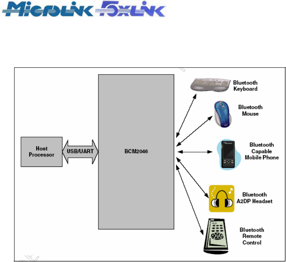
Figure 1 showsexample Bluetooth applications for the MNX-92P2
Figure 1: Example MNX-92P2 Bluetooth System Applications
MNX-92P2 PRD_V0 1.doc 6 2009/04/01
Specification
BT EDR Module With Antenna
MNX-92P2 (Broadcom 2.1 Based, Class 2)
FUNCTIONAL DESCRIPTION
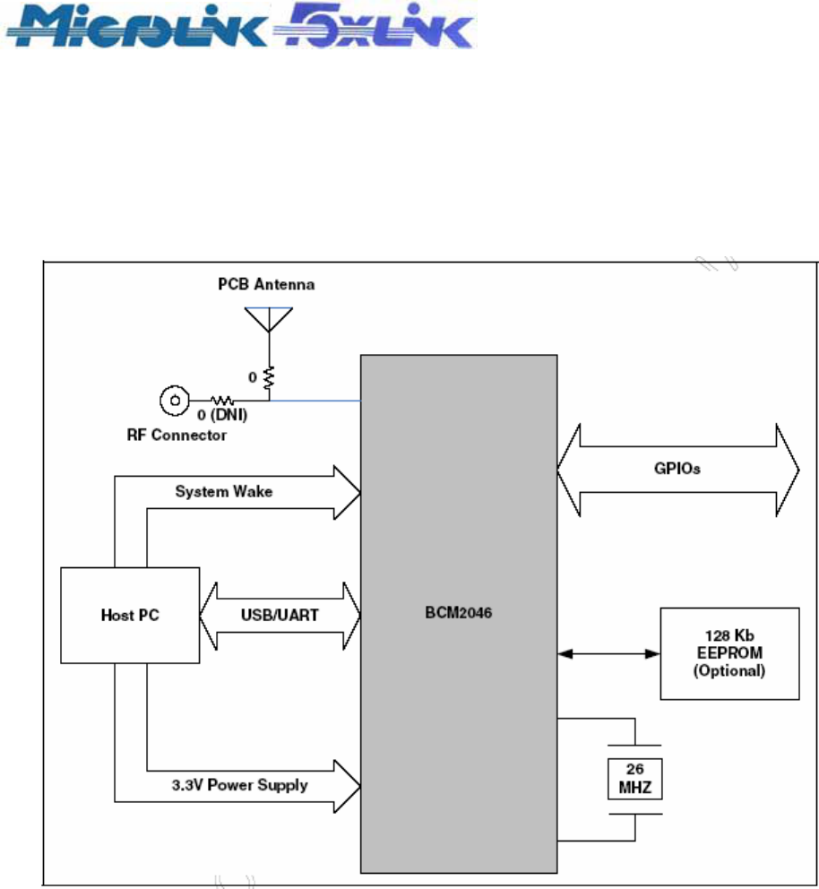
The primary component on the module is the Broadcom® BCM2046, which is a Bluetooth 2.1 compliant,
single-chip device. The baseband and radio have been implemented in standard digital CMOS. The block
diagram of the module is shown in Figure 2.
Figure 2: MNX-92P2 Block Diagram
The BCM2046 employs an integrated ARM7TDMIS™ 32-bit RISC processor with an embedded ICE-RT and
JTAG interface unit. The microprocessor executes software in all layers from the link control layer to the HCI
layer. The microprocessor includes 256 KB of program storage and boot code ROM and 48 KB of data
scratchpad and patch code RAM. The BCM2046 baseband section performs all of the time critical functions
required for high-performance Bluetooth operations.
The radio incorporates the complete receive and transmit paths, including the PLL, VCO, LNA, PA,
upconverter, downconverter, modulator, demodulator, and channel select filtering.
MNX-92P2 PRD_V0 1.doc 7 2009/04/01
Specification
BT EDR Module With Antenna
MNX-92P2 (Broadcom 2.1 Based, Class 2)
PHYSICAL DESCRIPTION
MODULE PINOUT
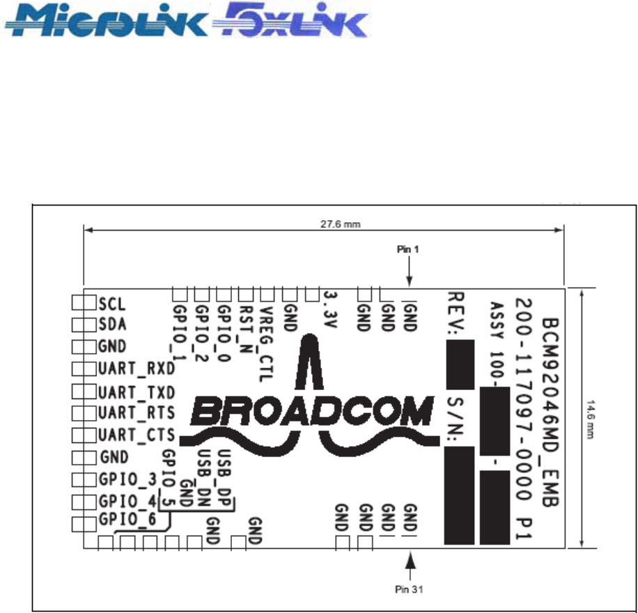
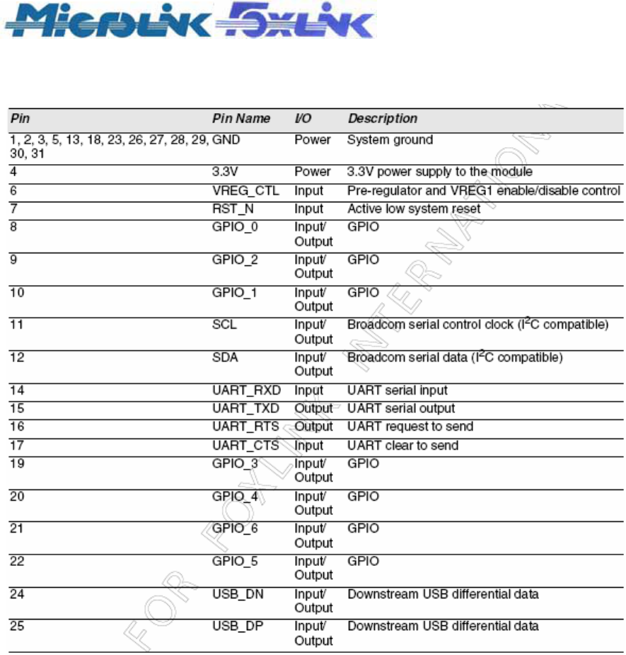
The MNX-92P2 is a 27.6 mm × 14.6 mm FR4 PCB with a maximum thickness of 0.925 mm (36.4 mil)
and 31 pads located around the perimeter. Figure 3 shows the module pinout diagram.
Figure 3 : MNX-92P2 Pinout
MNX-92P2 PRD_V0 1.doc 8 2009/04/01
Specification
BT EDR Module With Antenna
MNX-92P2 (Broadcom 2.1 Based, Class 2)
MODULE PINOUT DESCRIPTION
Table 1 shows the MNX-92P2 pinout description.
MNX-92P2 PRD_V0 1.doc 9 2009/04/01
Specification
BT EDR Module With Antenna
MNX-92P2 (Broadcom 2.1 Based, Class 2)
APPLICATION CODE
Application code resides in the on-module EEPROM. During power-on reset, the application code must be
downloaded to BCM2046 RAM before the board performs any Bluetooth activity.
Application code can also be patched directly to BCM2046 RAM from the host during power-on reset without
an external EEPROM.
The 2046 on-chip serial port can be used to download application code from a host computer file to EEPROM
or on-chip RAM using either the UART or USB transport mechanisms.
HARDWARE DESIGN CONSIDERATIONS
EEPROM (OPTIONAL)
A 128-Kbit EEPROM is used to store application code and configuration information.
CRYSTAL
The system design uses a 26 MHz crystal oscillator with an accuracy of ±8 ppm @25°C and ±12 ppm from
–20°C to +70°C, a 50∧ maximum ESR, a 10 pF load capacitance, a 200 ⎧W (maximum) drive level and a
±1ppm/yr (maximum) aging rate.
ANTENNA
A meander strip PCB antenna is placed on the reference board. The antenna is a variation of the printed
F-antenna and has characteristics similar to those of the F-antenna.
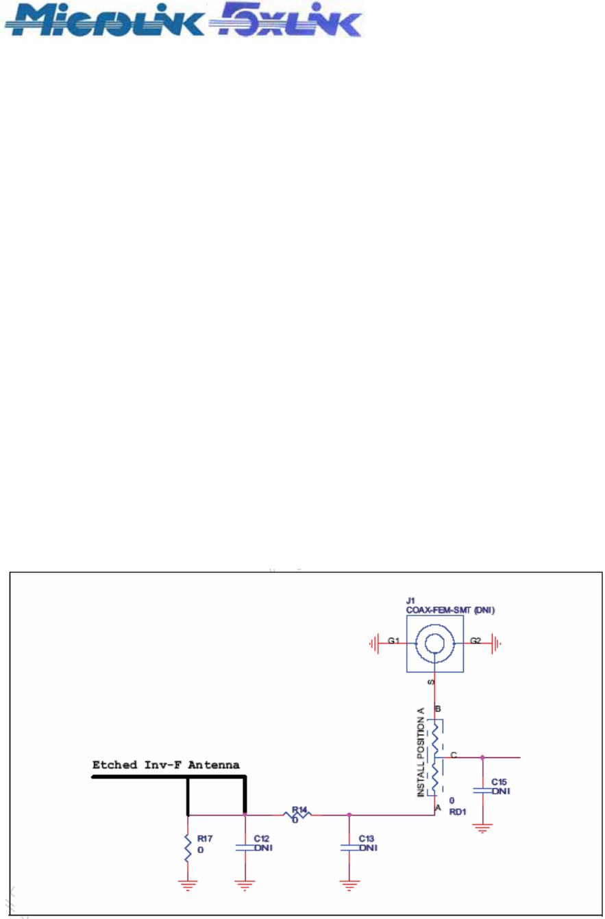
RF CONNECTOR
The MNX-92P2 has an optional RF connector, which is shown as J1 in Figure 4, that can be used in
some applications to connect to an external antenna for better performance.
To use the optional RF connector, populate J1 and install RD1 at position B.
Figure 4: MNX-92P2 Antenna Connection Option
MNX-92P2 PRD_V0 1.doc 10 2009/04/01
Specification
BT EDR Module With Antenna
MNX-92P2 (Broadcom 2.1 Based, Class 2)
Section 2: Supporting Documentation
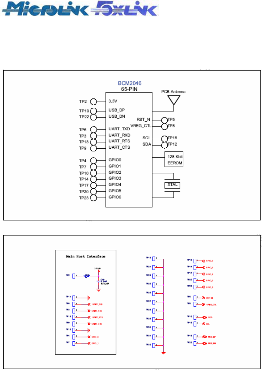
MNX-92P2 schematic.
Figure 5: MNX-92P2 Title Page (Page 1 of 2)
Figure 8: MNX-92P2 Interface Schematic (Page 2 of 2)

MNX-92P2 PRD_V0 1.doc 11 2009/04/01
Specification
BT EDR Module With Antenna
MNX-92P2 (Broadcom 2.1 Based, Class 2)
USB/UART CONFIGURATIONS
USB-ONLY CONFIGURATION
Do the following for the USB-only configuration:
• Install R1, R6, R7, R8 and do not install R2.
• Either pull up or float UART_CTS_N (pin C8). It is internally pulled up.
• Connect VDDUSB (pin G8), VBATT (pin A2), and VREG_CTL (pin B3) to the system 3.3V. If VREG_CTL
is connected to a different power source, the delay between VREG_CTL and VBATT during power-up may
cause a leakage current to flow through the USB_DN pad.
UART-ONLY CONFIGURATION
Do the following for the UART-only configuration:
• Install R2 and do not install R1, R6, R7, R8.
• (Recommended) Ground VDD_USB (pin G8). USB_DP (pin H7) and USB_DN (pin J8) can be either
grounded or left floating.
MNX-92P2 PRD_V0 1.doc 12 2009/04/01
Specification
BT EDR Module With Antenna
MNX-92P2 (Broadcom 2.1 Based, Class 2)
PCB ANTENNA DESIGN CONSIDERATIONS
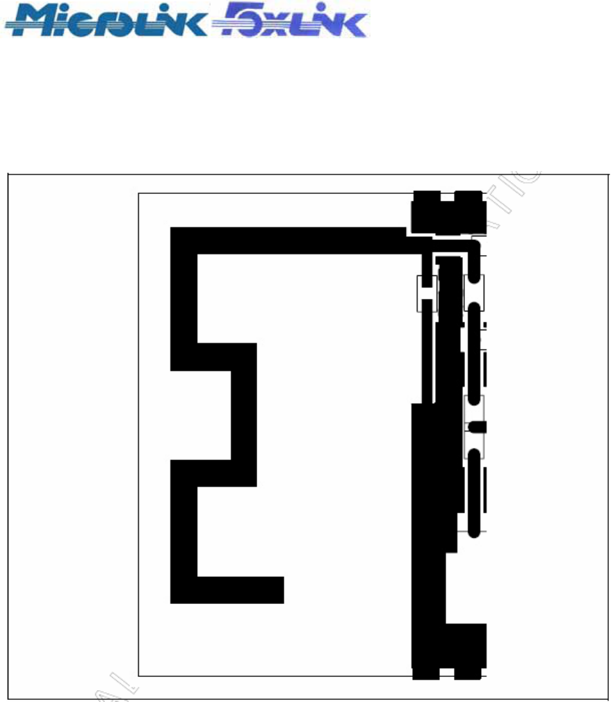
The following antenna design practices should be applied for optimal antenna performance:
• Do not place a copper plane underneath the antenna.
• Use a PCB edge to antenna clearing of at least one antenna trace width.
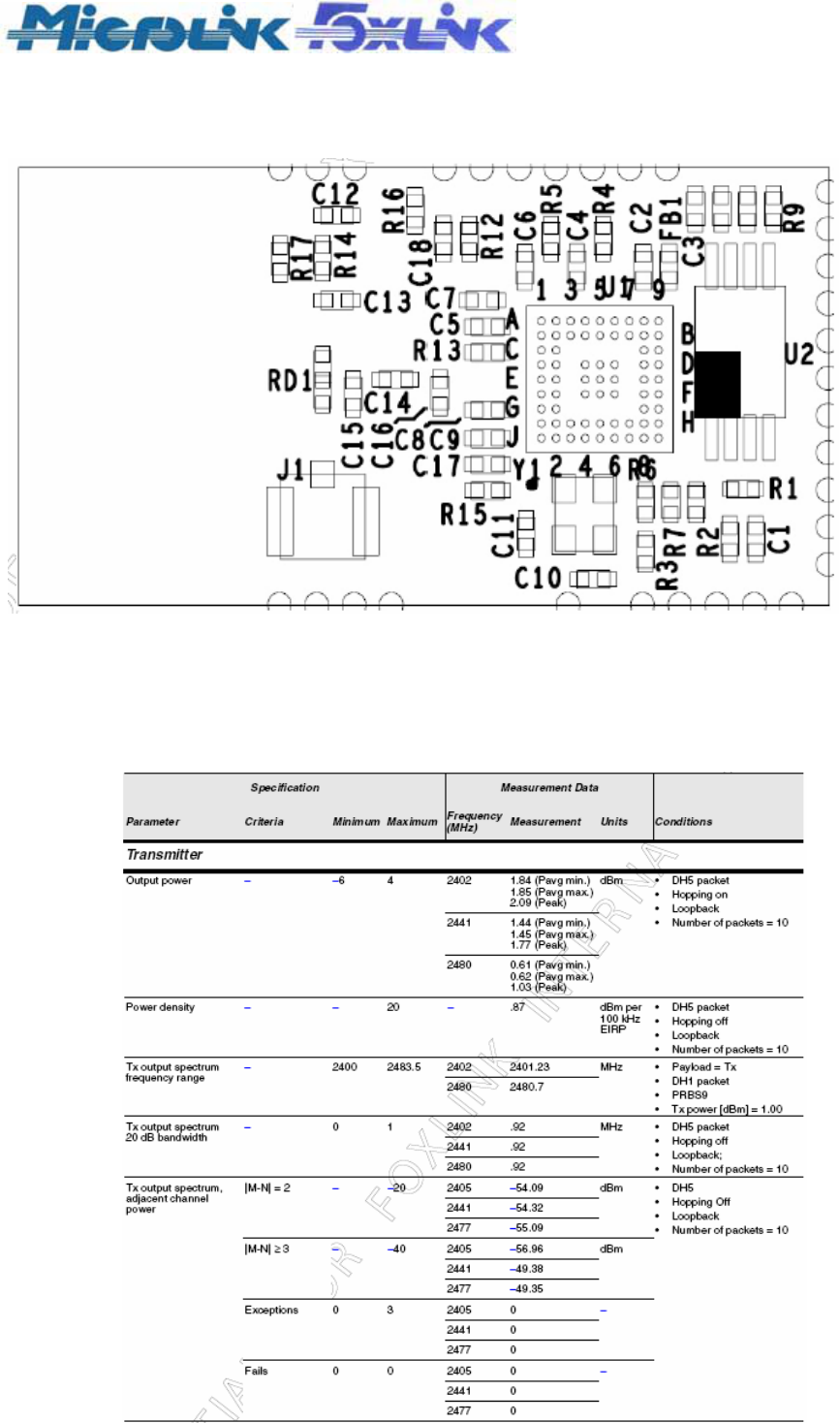
Figure 9 shows the MNX-92P2 antenna section.
Figure 9: MNX-92P2 Antenna
MNX-92P2 PRD_V0 1.doc 13 2009/04/01
Specification
BT EDR Module With Antenna
MNX-92P2 (Broadcom 2.1 Based, Class 2)
PCB LAYOUT
COMPONENT PLACEMENT
Figure 11: MNX-92P2 Component Placement
MODULE RF SPECIFICATIONS AND MEASUREMENTS
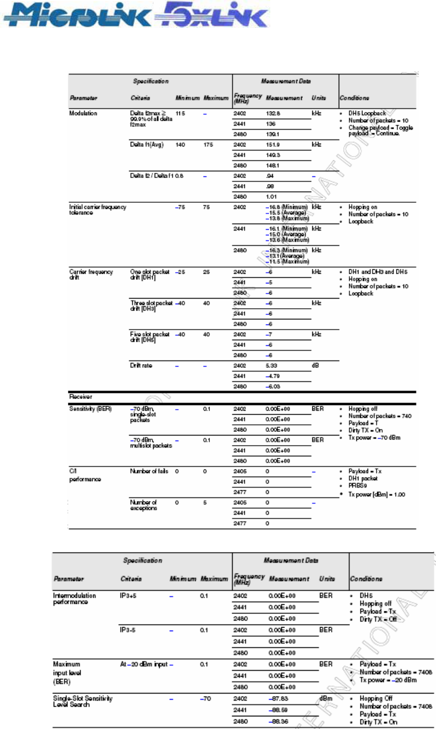
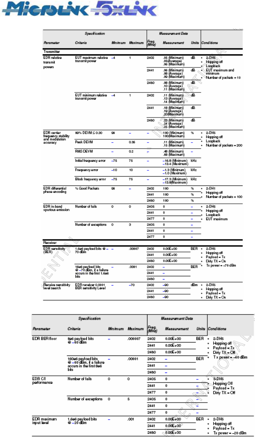
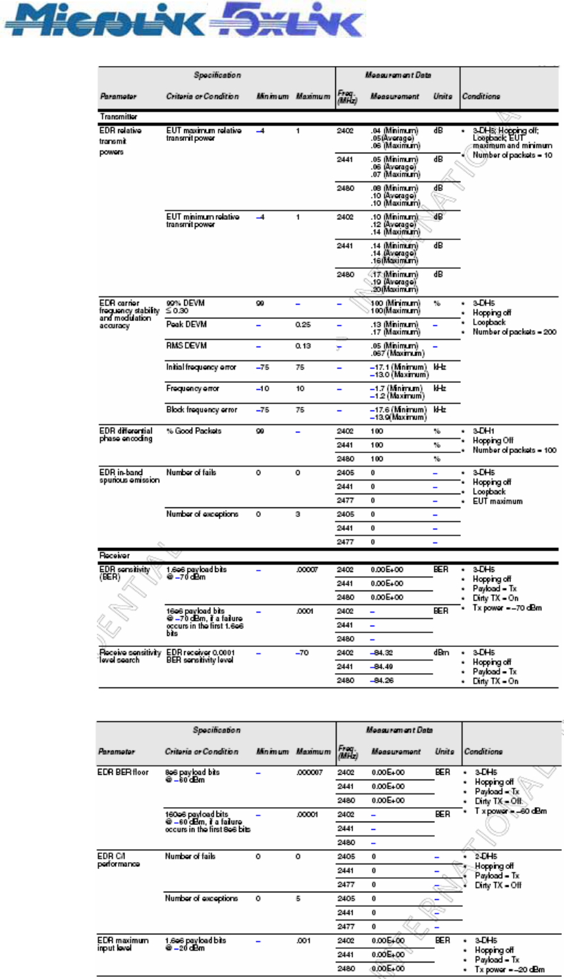
Table 3, Table 4 on page 19, and Table 5 on page 21 show the Class 2 RF specifications and measurements
as referenced to the module’s RF input/output port without the PCB antenna (that is, all measurements are
conducted not radiated).
Table 3: Module Class 2 GFSK RF Specification (T = 25° C)
MNX-92P2 PRD_V0 1.doc 14 2009/04/01
Specification
BT EDR Module With Antenna
MNX-92P2 (Broadcom 2.1 Based, Class 2)
Table 3: Module Class 2 GFSK RF Specification (T = 25° C) (Cont.)
Table 3: Module Class 2 GFSK RF Specification (T = 25° C) (Cont.)
MNX-92P2 PRD_V0 1.doc 15 2009/04/01
Specification
BT EDR Module With Antenna
MNX-92P2 (Broadcom 2.1 Based, Class 2)
Table 4: Module Class 2 EDR RF 2 MBPS Specification (T = 25° C)
Table 4: Module Class 2 EDR RF 2 MBPS Specification (T = 25° C) (Cont.)
MNX-92P2 PRD_V0 1.doc 16 2009/04/01
Specification
BT EDR Module With Antenna
MNX-92P2 (Broadcom 2.1 Based, Class 2)
Table 5: Module Class 2 EDR RF 3MBPS Specification (T = 25° C)
Table 5: Module Class 2 EDR RF 3MBPS Specification (T = 25° C) (Cont.)