Topcon America 050902 GR 3, 01-050901-22 User Manual Installation Manual
Topcon America Corporation GR 3, 01-050901-22 Installation Manual
UserManual.wiki
>
Topcon America
>
050902 User Manual
>
Installation Manual
Contents
1.
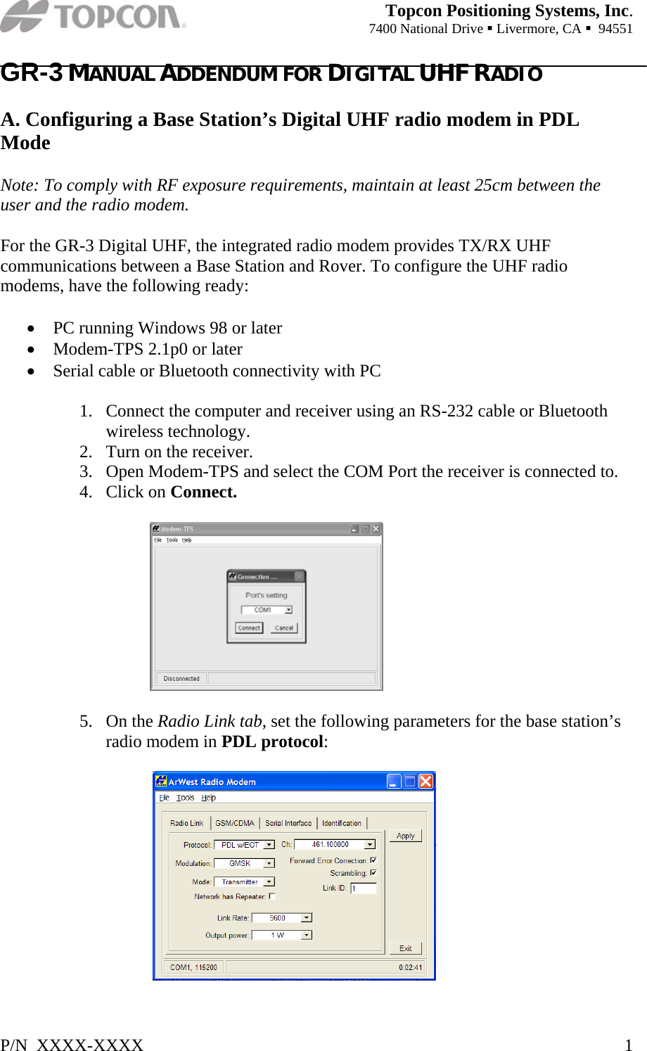
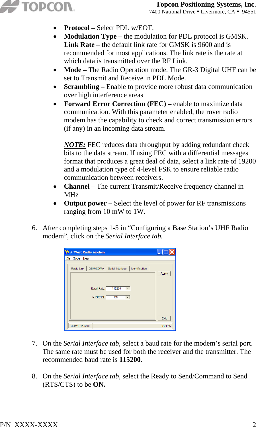
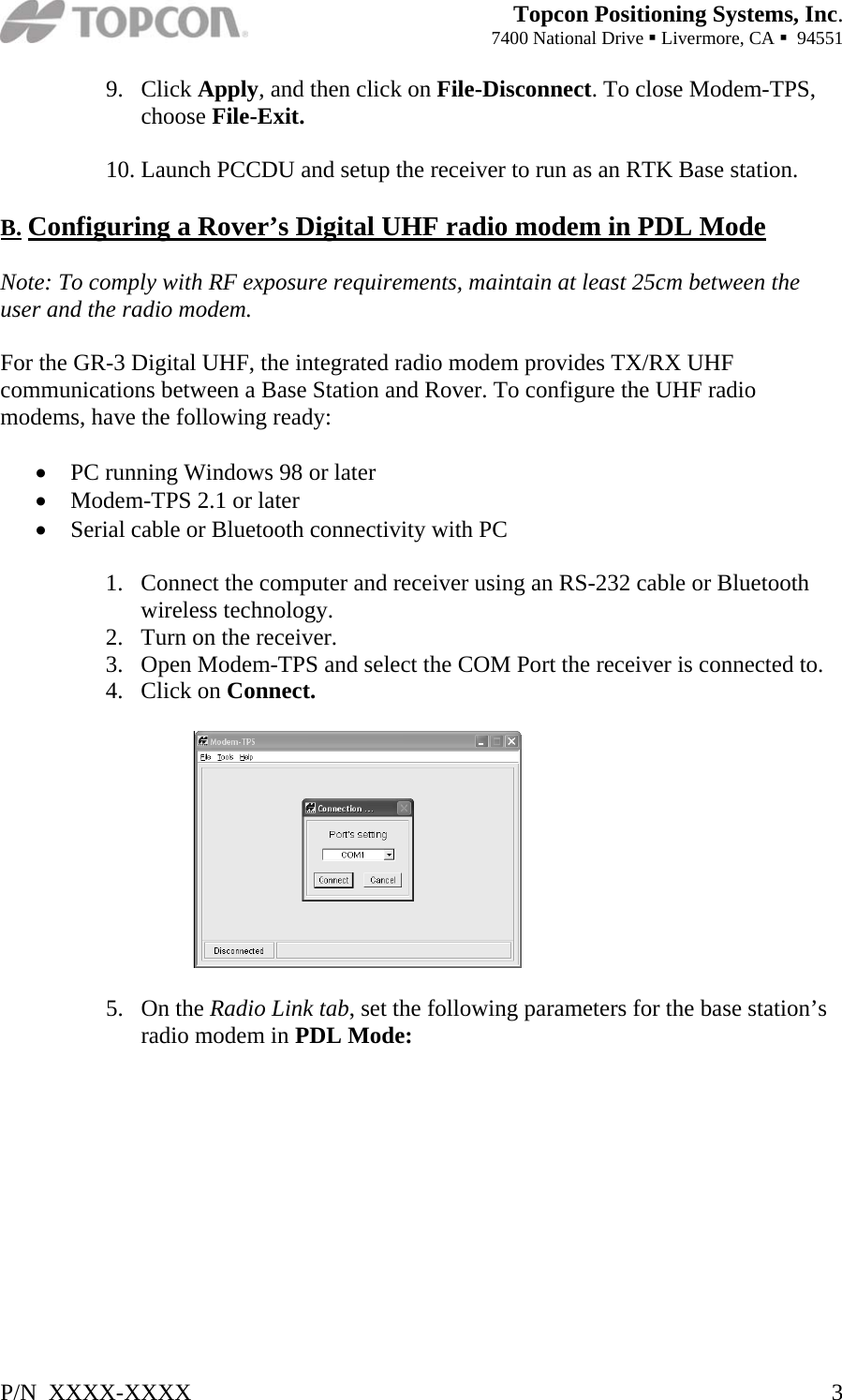
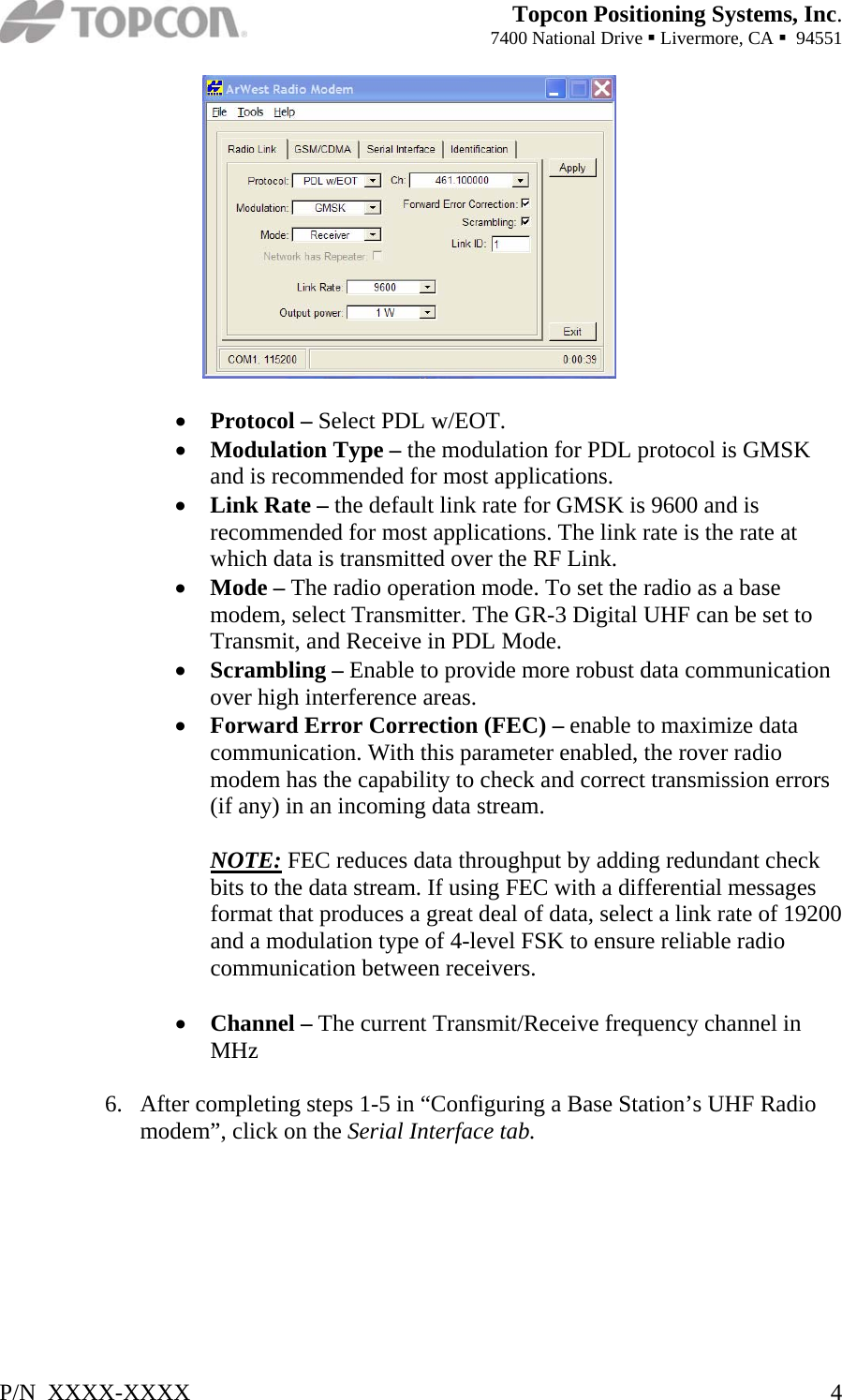
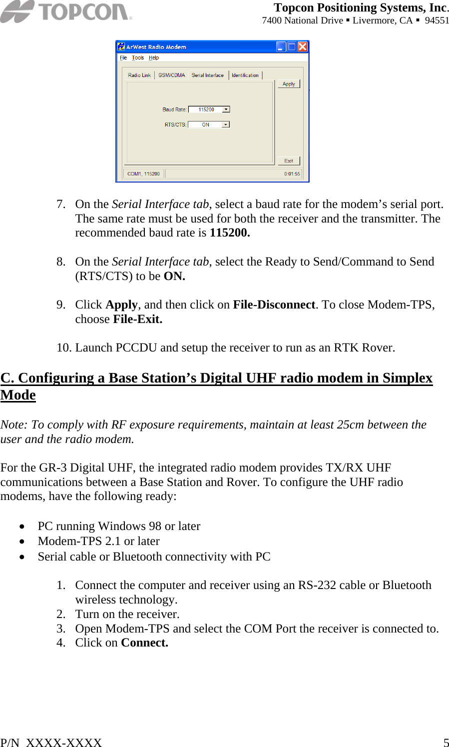
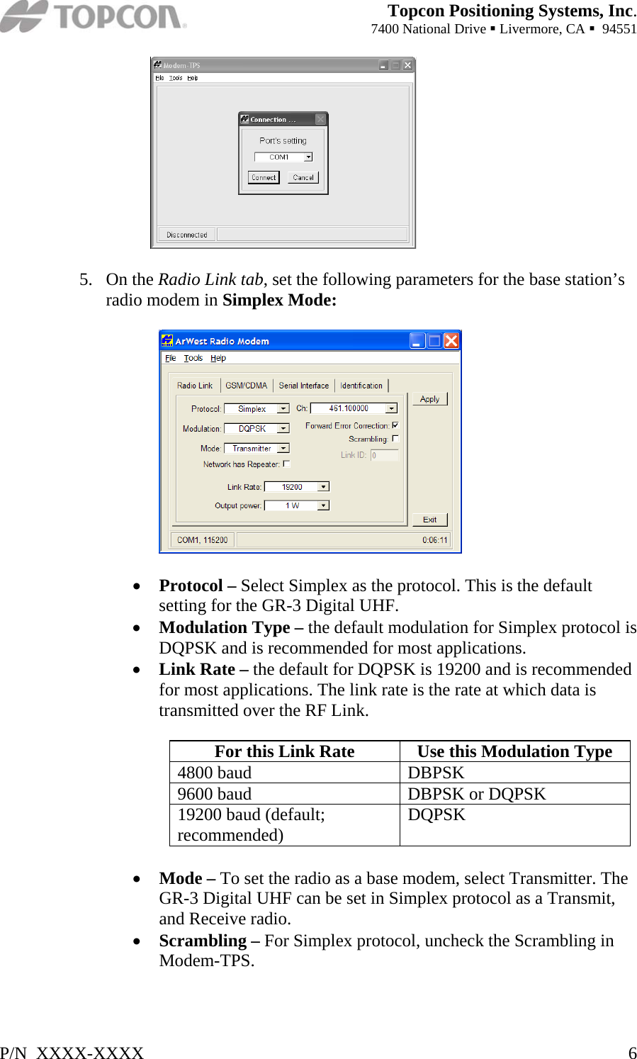
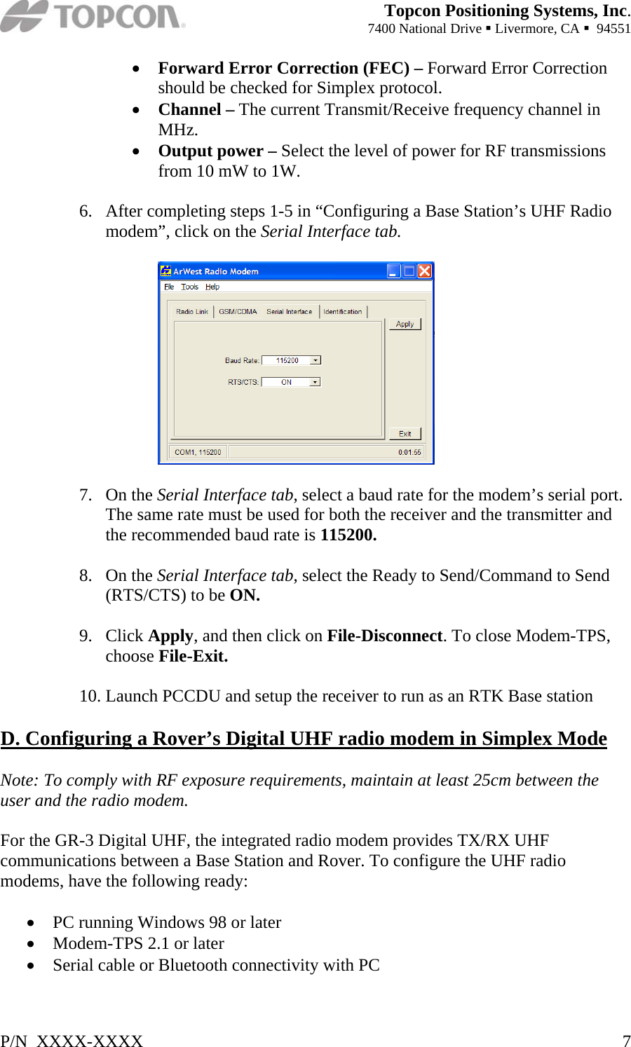
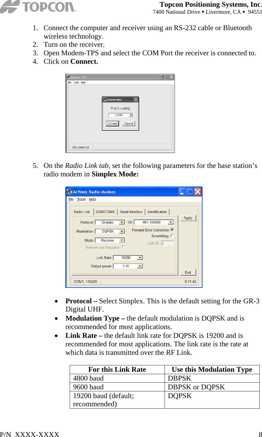
Installation Manual
2.
Users Manual
Installation Manual
Navigation menu
Upload a User Manual
Namespaces
Wiki Guide
HTML
PDF
Info
Views
User Manual
Discussion / Help
Navigation