Topcon America 050902 GR 3, 01-050901-22 User Manual Installation Manual
Topcon America Corporation GR 3, 01-050901-22 Installation Manual
Contents
- 1. Installation Manual
- 2. Users Manual
Installation Manual
Topcon Positioning Systems, Inc.
7400 National Drive Livermore, CA 94551
P/N XXXX-XXXX 1
GR-3 MANUAL ADDENDUM FOR DIGITAL UHF RADIO
A. Configuring a Base Station’s Digital UHF radio modem in PDL
Mode
Note: To comply with RF exposure requirements, maintain at least 25cm between the
user and the radio modem.
For the GR-3 Digital UHF, the integrated radio modem provides TX/RX UHF
communications between a Base Station and Rover. To configure the UHF radio
modems, have the following ready:
• PC running Windows 98 or later
• Modem-TPS 2.1p0 or later
• Serial cable or Bluetooth connectivity with PC
1. Connect the computer and receiver using an RS-232 cable or Bluetooth
wireless technology.
2. Turn on the receiver.
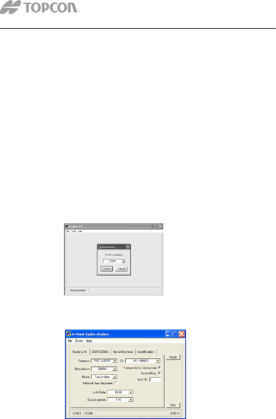
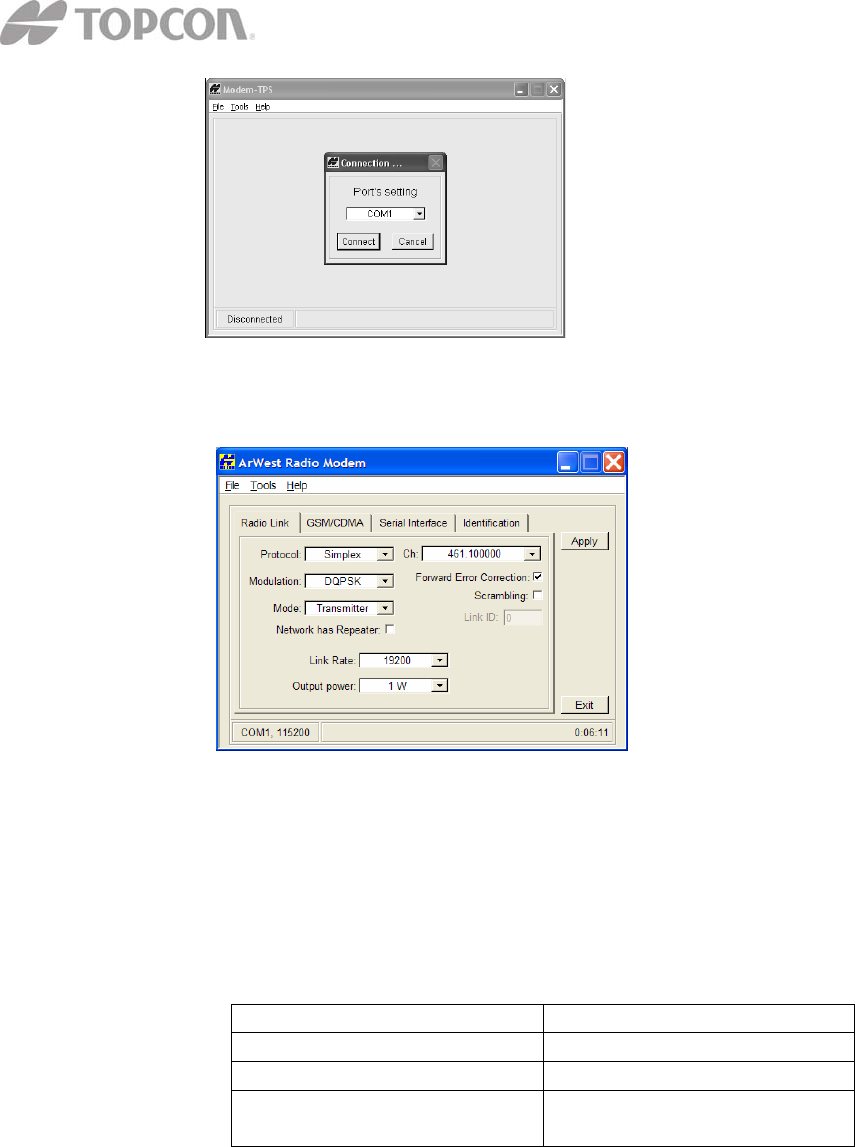
3. Open Modem-TPS and select the COM Port the receiver is connected to.
4. Click on Connect.
5. On the Radio Link tab, set the following parameters for the base station’s
radio modem in PDL protocol:
Topcon Positioning Systems, Inc.
7400 National Drive Livermore, CA 94551
P/N XXXX-XXXX 2
• Protocol – Select PDL w/EOT.
• Modulation Type – the modulation for PDL protocol is GMSK.
Link Rate – the default link rate for GMSK is 9600 and is
recommended for most applications. The link rate is the rate at
which data is transmitted over the RF Link.
• Mode – The Radio Operation mode. The GR-3 Digital UHF can be
set to Transmit and Receive in PDL Mode.
• Scrambling – Enable to provide more robust data communication
over high interference areas
• Forward Error Correction (FEC) – enable to maximize data
communication. With this parameter enabled, the rover radio
modem has the capability to check and correct transmission errors
(if any) in an incoming data stream.
NOTE: FEC reduces data throughput by adding redundant check
bits to the data stream. If using FEC with a differential messages
format that produces a great deal of data, select a link rate of 19200
and a modulation type of 4-level FSK to ensure reliable radio
communication between receivers.
• Channel – The current Transmit/Receive frequency channel in
MHz
• Output power – Select the level of power for RF transmissions
ranging from 10 mW to 1W.
6. After completing steps 1-5 in “Configuring a Base Station’s UHF Radio
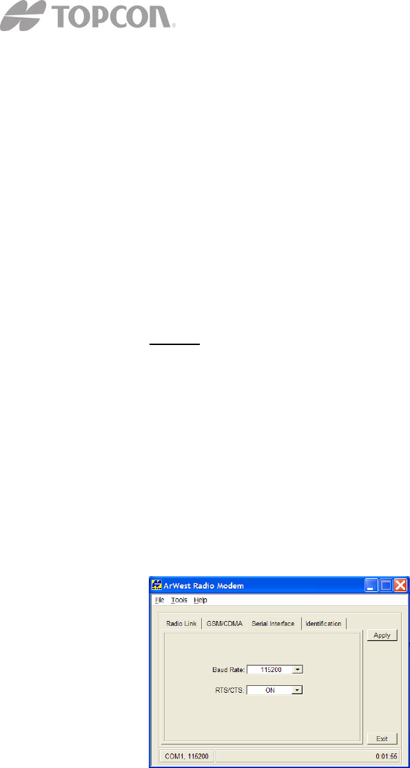
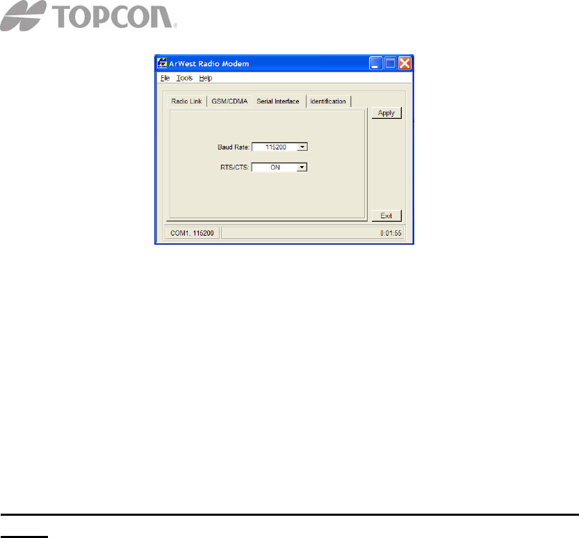
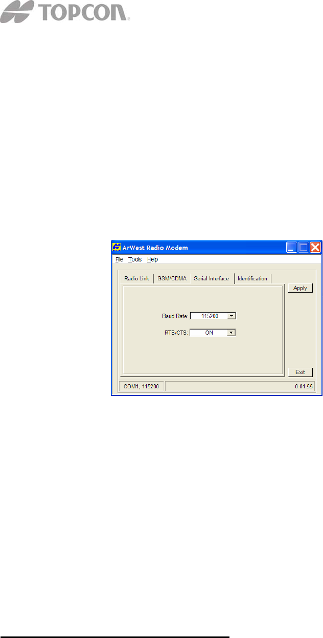
modem”, click on the Serial Interface tab.
7. On the Serial Interface tab, select a baud rate for the modem’s serial port.
The same rate must be used for both the receiver and the transmitter. The
recommended baud rate is 115200.
8. On the Serial Interface tab, select the Ready to Send/Command to Send
(RTS/CTS) to be ON.
Topcon Positioning Systems, Inc.
7400 National Drive Livermore, CA 94551
P/N XXXX-XXXX 3
9. Click Apply, and then click on File-Disconnect. To close Modem-TPS,
choose File-Exit.
10. Launch PCCDU and setup the receiver to run as an RTK Base station.
B. Configuring a Rover’s Digital UHF radio modem in PDL Mode
Note: To comply with RF exposure requirements, maintain at least 25cm between the
user and the radio modem.
For the GR-3 Digital UHF, the integrated radio modem provides TX/RX UHF
communications between a Base Station and Rover. To configure the UHF radio
modems, have the following ready:
• PC running Windows 98 or later
• Modem-TPS 2.1 or later
• Serial cable or Bluetooth connectivity with PC
1. Connect the computer and receiver using an RS-232 cable or Bluetooth
wireless technology.
2. Turn on the receiver.
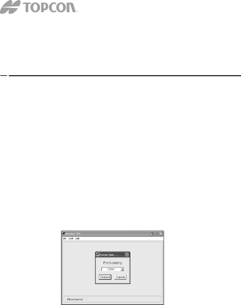
3. Open Modem-TPS and select the COM Port the receiver is connected to.
4. Click on Connect.
5. On the Radio Link tab, set the following parameters for the base station’s
radio modem in PDL Mode:
Topcon Positioning Systems, Inc.
7400 National Drive Livermore, CA 94551
P/N XXXX-XXXX 4
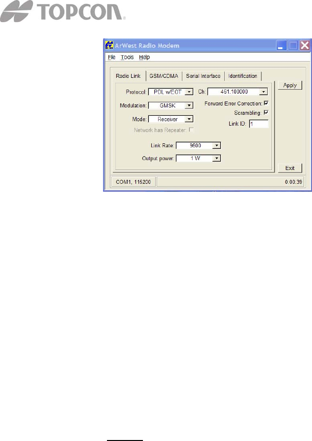
• Protocol – Select PDL w/EOT.
• Modulation Type – the modulation for PDL protocol is GMSK
and is recommended for most applications.
• Link Rate – the default link rate for GMSK is 9600 and is
recommended for most applications. The link rate is the rate at
which data is transmitted over the RF Link.
• Mode – The radio operation mode. To set the radio as a base
modem, select Transmitter. The GR-3 Digital UHF can be set to
Transmit, and Receive in PDL Mode.
• Scrambling – Enable to provide more robust data communication
over high interference areas.
• Forward Error Correction (FEC) – enable to maximize data
communication. With this parameter enabled, the rover radio
modem has the capability to check and correct transmission errors
(if any) in an incoming data stream.
NOTE: FEC reduces data throughput by adding redundant check
bits to the data stream. If using FEC with a differential messages
format that produces a great deal of data, select a link rate of 19200
and a modulation type of 4-level FSK to ensure reliable radio
communication between receivers.
• Channel – The current Transmit/Receive frequency channel in
MHz
6. After completing steps 1-5 in “Configuring a Base Station’s UHF Radio
modem”, click on the Serial Interface tab.
Topcon Positioning Systems, Inc.
7400 National Drive Livermore, CA 94551
P/N XXXX-XXXX 5
7. On the Serial Interface tab, select a baud rate for the modem’s serial port.
The same rate must be used for both the receiver and the transmitter. The
recommended baud rate is 115200.
8. On the Serial Interface tab, select the Ready to Send/Command to Send
(RTS/CTS) to be ON.
9. Click Apply, and then click on File-Disconnect. To close Modem-TPS,
choose File-Exit.
10. Launch PCCDU and setup the receiver to run as an RTK Rover.
C. Configuring a Base Station’s Digital UHF radio modem in Simplex
Mode
Note: To comply with RF exposure requirements, maintain at least 25cm between the
user and the radio modem.
For the GR-3 Digital UHF, the integrated radio modem provides TX/RX UHF
communications between a Base Station and Rover. To configure the UHF radio
modems, have the following ready:
• PC running Windows 98 or later
• Modem-TPS 2.1 or later
• Serial cable or Bluetooth connectivity with PC
1. Connect the computer and receiver using an RS-232 cable or Bluetooth
wireless technology.
2. Turn on the receiver.
3. Open Modem-TPS and select the COM Port the receiver is connected to.
4. Click on Connect.
Topcon Positioning Systems, Inc.
7400 National Drive Livermore, CA 94551
P/N XXXX-XXXX 6
5. On the Radio Link tab, set the following parameters for the base station’s
radio modem in Simplex Mode:
• Protocol – Select Simplex as the protocol. This is the default
setting for the GR-3 Digital UHF.
• Modulation Type – the default modulation for Simplex protocol is
DQPSK and is recommended for most applications.
• Link Rate – the default for DQPSK is 19200 and is recommended
for most applications. The link rate is the rate at which data is
transmitted over the RF Link.
For this Link Rate Use this Modulation Type
4800 baud DBPSK
9600 baud DBPSK or DQPSK
19200 baud (default;
recommended) DQPSK
• Mode – To set the radio as a base modem, select Transmitter. The
GR-3 Digital UHF can be set in Simplex protocol as a Transmit,
and Receive radio.
• Scrambling – For Simplex protocol, uncheck the Scrambling in
Modem-TPS.
Topcon Positioning Systems, Inc.
7400 National Drive Livermore, CA 94551
P/N XXXX-XXXX 7
• Forward Error Correction (FEC) – Forward Error Correction
should be checked for Simplex protocol.
• Channel – The current Transmit/Receive frequency channel in
MHz.
• Output power – Select the level of power for RF transmissions
from 10 mW to 1W.
6. After completing steps 1-5 in “Configuring a Base Station’s UHF Radio
modem”, click on the Serial Interface tab.
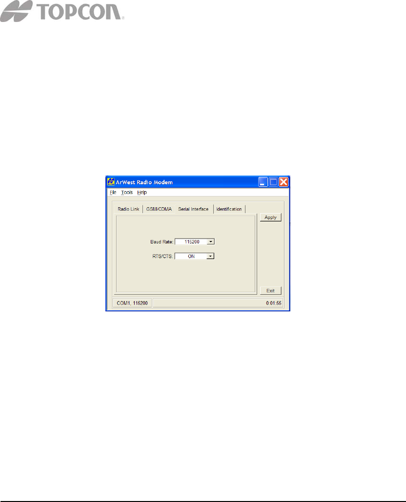
7. On the Serial Interface tab, select a baud rate for the modem’s serial port.
The same rate must be used for both the receiver and the transmitter and
the recommended baud rate is 115200.
8. On the Serial Interface tab, select the Ready to Send/Command to Send
(RTS/CTS) to be ON.
9. Click Apply, and then click on File-Disconnect. To close Modem-TPS,
choose File-Exit.
10. Launch PCCDU and setup the receiver to run as an RTK Base station
D. Configuring a Rover’s Digital UHF radio modem in Simplex Mode
Note: To comply with RF exposure requirements, maintain at least 25cm between the
user and the radio modem.
For the GR-3 Digital UHF, the integrated radio modem provides TX/RX UHF
communications between a Base Station and Rover. To configure the UHF radio
modems, have the following ready:
• PC running Windows 98 or later
• Modem-TPS 2.1 or later
• Serial cable or Bluetooth connectivity with PC
Topcon Positioning Systems, Inc.
7400 National Drive Livermore, CA 94551
P/N XXXX-XXXX 8
1. Connect the computer and receiver using an RS-232 cable or Bluetooth
wireless technology.
2. Turn on the receiver.
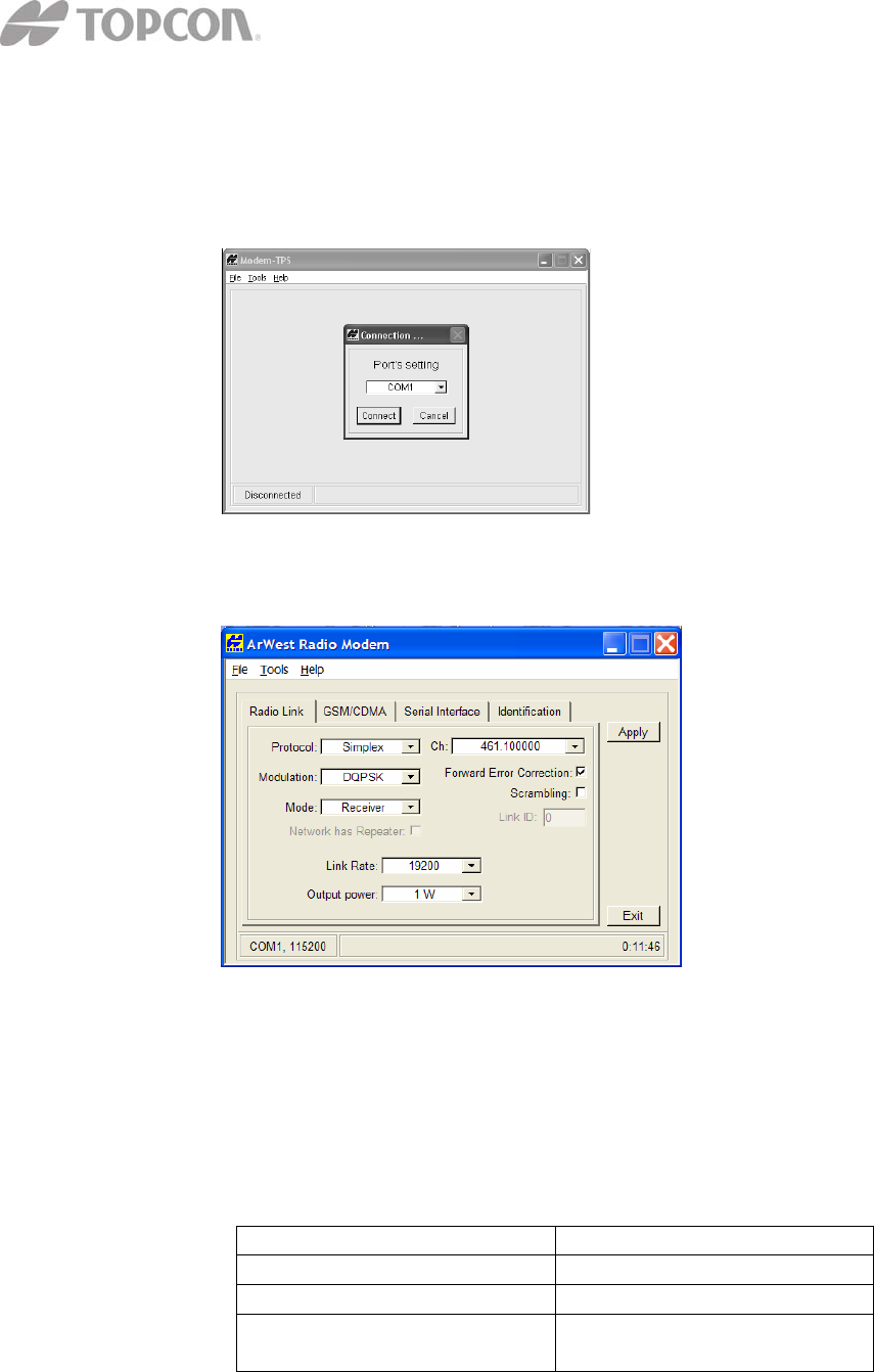
3. Open Modem-TPS and select the COM Port the receiver is connected to.
4. Click on Connect.
5. On the Radio Link tab, set the following parameters for the base station’s
radio modem in Simplex Mode:
• Protocol – Select Simplex. This is the default setting for the GR-3
Digital UHF.
• Modulation Type – the default modulation is DQPSK and is
recommended for most applications.
• Link Rate – the default link rate for DQPSK is 19200 and is
recommended for most applications. The link rate is the rate at
which data is transmitted over the RF Link.
For this Link Rate Use this Modulation Type
4800 baud DBPSK
9600 baud DBPSK or DQPSK
19200 baud (default;
recommended) DQPSK
Topcon Positioning Systems, Inc.
7400 National Drive Livermore, CA 94551
P/N XXXX-XXXX 9
• Mode – To set the radio as a base modem, select Transmitter. The
GR-3 Digital UHF in Simplex mode can be set as a Transmitter
and Receiver.
• Scrambling – For Simplex protocol, disable the scrambling in
Modem-TPS.
Forward Error Correction (FEC) – For Simplex protocol,
enable FEC in Modem-TPS.
• Channel – The current Transmit/Receive frequency channel in
MHz
6. After completing steps 1-5 in “Configuring a Base Station’s UHF Radio
modem”, click on the Serial Interface tab.
7. On the Serial Interface tab, select a baud rate for the modem’s serial port.
The same rate must be used for both the receiver and the transmitter and
the recommended baud rate is 115200.
8. On the Serial Interface tab, select the Ready to Send/Command to Send
(RTS/CTS) to be ON.
9. Click Apply, then click on File-Disconnect. To close Modem-TPS,
choose File-Exit.
10. Launch PCCDU and setup the receiver to run as an RTK Rover.
E. Configuring a GSM Radio Modem
Note: To comply with RF exposure requirements, maintain at least 25cm between the
user and the radio modem.
Topcon Positioning Systems, Inc.
7400 National Drive Livermore, CA 94551
P/N XXXX-XXXX 10
For the GR-3 Digital UHF, the integrated radio modem with a Wavecom GSM Module
provides TX/RX GSM communications between a Base Station and Rover, or
communications with a GPS network using IP based connections. To configure the GSM
modems, have the following ready:
• PC running Windows 98 or later
• Modem-TPS 2.1 or later
• Serial cable or Bluetooth connectivity with PC
1. Connect the computer and receiver using an RS-232 cable or Bluetooth
wireless technology.
2. Turn on the receiver.
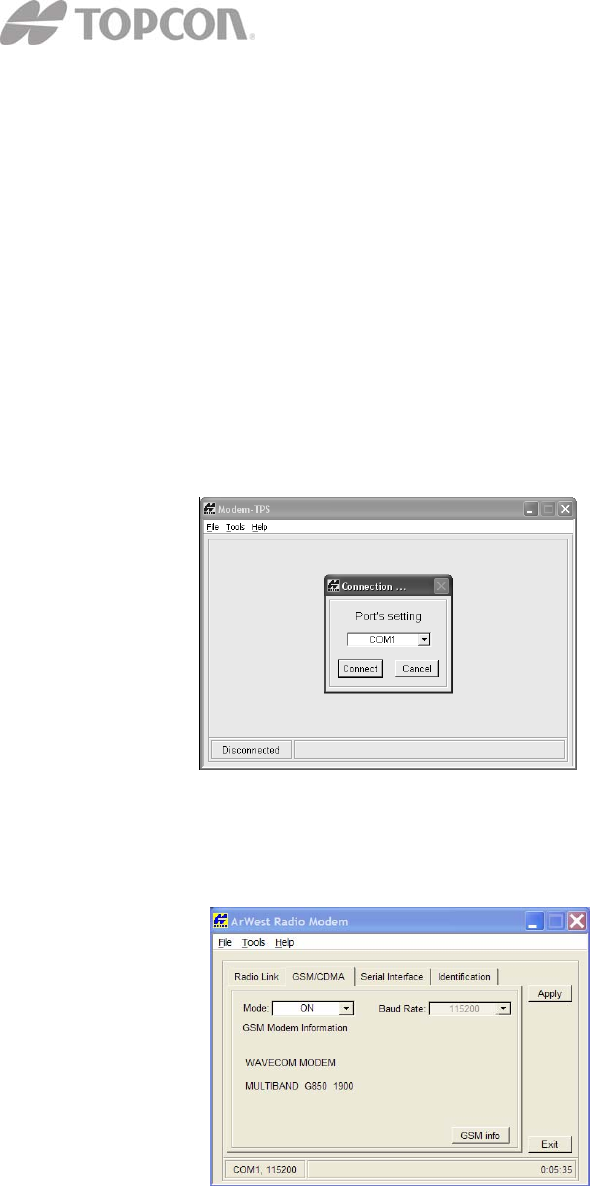
3. Open Modem-TPS and select the COM Port the receiver is connected to.
4. Click on Connect.
5. Once connected select the GSM/CDMA tab in Modem-TPS.
6. Select the Mode as ON and click Apply to enable the GSM Module.
7. The Wavecom GSM modem can either be in the US GSM band (GSM
850/1900 MHz as in the image above) or the European GSM band
(900/1800 MHz). To view the GSM modem information, click on GSM
Info. Click on Quit to return to the GSM tab.
Topcon Positioning Systems, Inc.
7400 National Drive Livermore, CA 94551
P/N XXXX-XXXX 11
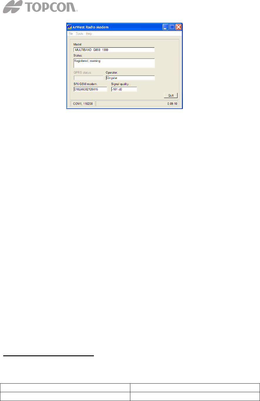
• Signal quality is a reading of the strength of the GSM signal. The
lower the number – the closer to zero 0 – the better the signal
quality. The minimum signal cutoff is -111 dB.
• The Operator is the service provider on the SIM card inserted into
the GR-3 Digital UHF
• The Model shows the model of the Wavecom module and the
GSM band that it uses.
• The S/N GSM modem reports the electronic serial number of the
Wavecom GSM module inside the GR-3 Digital UHF.
• The status shows whether the SIM card inserted into the GR-3 is
registered on the service provider’s network. It will report one of
three things.
o Registered, home network
o Registered, roaming
o Not registered
Note: As long as the SIM card is registered, it will work even
though it may be roaming.
8. On the Serial Interface tab, select a baud rate for the modem’s serial port.
For the Wavecom GSM modem in the GR-3 digital UHF, this must be set
to 115200.
9. Click Apply, and then click File-Disconnect.
10. If needed, launch PC-CDU and setup the receiver to run as an RTK Base
station.
F. Troubleshooting Guide
Receiver Problems
Problem Solution
The RX/TX LED is flashing green on my • The base has been set into Receiver

Topcon Positioning Systems, Inc.
7400 National Drive Livermore, CA 94551
P/N XXXX-XXXX 12
base receiver mode, not transmit mode. Change
this using the data collector
software or Modem-TPS.
• The base is set into GSM mode.
Change this using data collector
software or Modem-TPS.
I have no radio link between base and rover
and the Rx/TX LED is flashing green on
the rover.
• The LED indicates that the receiver
is set into Receive mode; however
no radio link has been established
• Check to make sure that the base
receiver is powered on
• Check to make sure that the base
and rover receivers are on the same
channel.
• Check to make sure the rover is not
set into GSM mode.
I have no radio link between base and rover
and the rover RX/TX LED is solid green
• The LED indicates that the rover
has established radio link with the
base receiver, however it is not
receiving RTK Corrections.
• Check to make sure that the base is
tracking enough satellites.
• Check to make sure that the base is
transmitting via a radio scanner or
by setting up the base receiver with
PC-CDU or application software.
The RX/TX LED is flashing red on my
receiver
• A fault condition has been detected.
• Check the radio modem’s antenna
to see if it is undamaged.
• Check to see if the radio antenna is
connected properly and securely
Internal Digital UHF Modem Specifications
General Specifications
Parameter Specification
Operating Frequency Range
country/region/purpose dependent 410-470 MHz
Modulation Techniques GMSK, 4-level FSK, DBPSK, DQPSK,
D8PSK, and 16QAM
Channel Spacing 12.5 kHz/25 kHz
Transmission Rates at 25 kHz spacing • DBPSK/GMSK – 9600 bps
• DQPSK/4FSK – 19200 bps
• D8PSK – 28800 bps

Topcon Positioning Systems, Inc.
7400 National Drive Livermore, CA 94551
P/N XXXX-XXXX 13
• D16QAM – 38400 bps
Transmission Rates at 12.5 kHz spacing • DBPSK/GMSK – 4800 bps
• DQPSK/4FSK – 9600 bps
• D8PSK – 14400 bps
• D16QAM – 19200 bps
Data Speed of Serial Interface Max 115200 bps
Forward Error Correction Available
Scrambling Available
Communication Mode Half-Duplex
Digital UHF Transmitter Specifications
Parameter Specification
Output Power 0.01 W (+10dBm), 0.02 W (+13 dBm),
0.05 W (+17 dBm), 0.1 W (+20 dBm),
0.25W (+24 dBm), 0.5 W (+27 dBm), 1W
(+30 dBm)
Nominal Output Impedance 50 Ohms 2.0:1 VSWR
Output Power Control Accuracy + 1dB (at normal test condition)
+2.0 dB and -3.0 dB (under extreme test
condition0
Digital UHF Receiver Specifications
Parameter Specification
Receiver Sensitivity for DBPSK (@ BER
<1x10⁻⁴ , over temperature -30°C to +60°C -115 dBm for 25 kHz Channel Spacing
-116 dBm for 12.5 kHz Channel Spacing
Adjacent Channel Selectivity -70 dB for 25 kHz Channel Spacing
-60 dB for 12.5 kHz Channel Spacing
Nominal Output Impedance 50 Ohms 2.0:1 VSWR
Output Power Control Accuracy + 1dB (at normal test condition)
+2.0 dB and -3.0 dB (under extreme test
condition0