Topcon America 090531 GNSS Receiver User Manual Introduction
Topcon America Corporation GNSS Receiver Introduction
UserManual.wiki
>
Topcon America
>
090531 User Manual
>
Manual 1
Contents
1.
Manual 1
2.
Manual 2
Manual 1
Navigation menu
Upload a User Manual
Namespaces
Wiki Guide
HTML
PDF
Info
Views
User Manual
Discussion / Help
Navigation
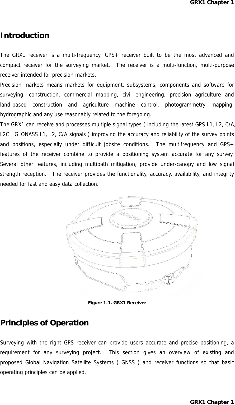
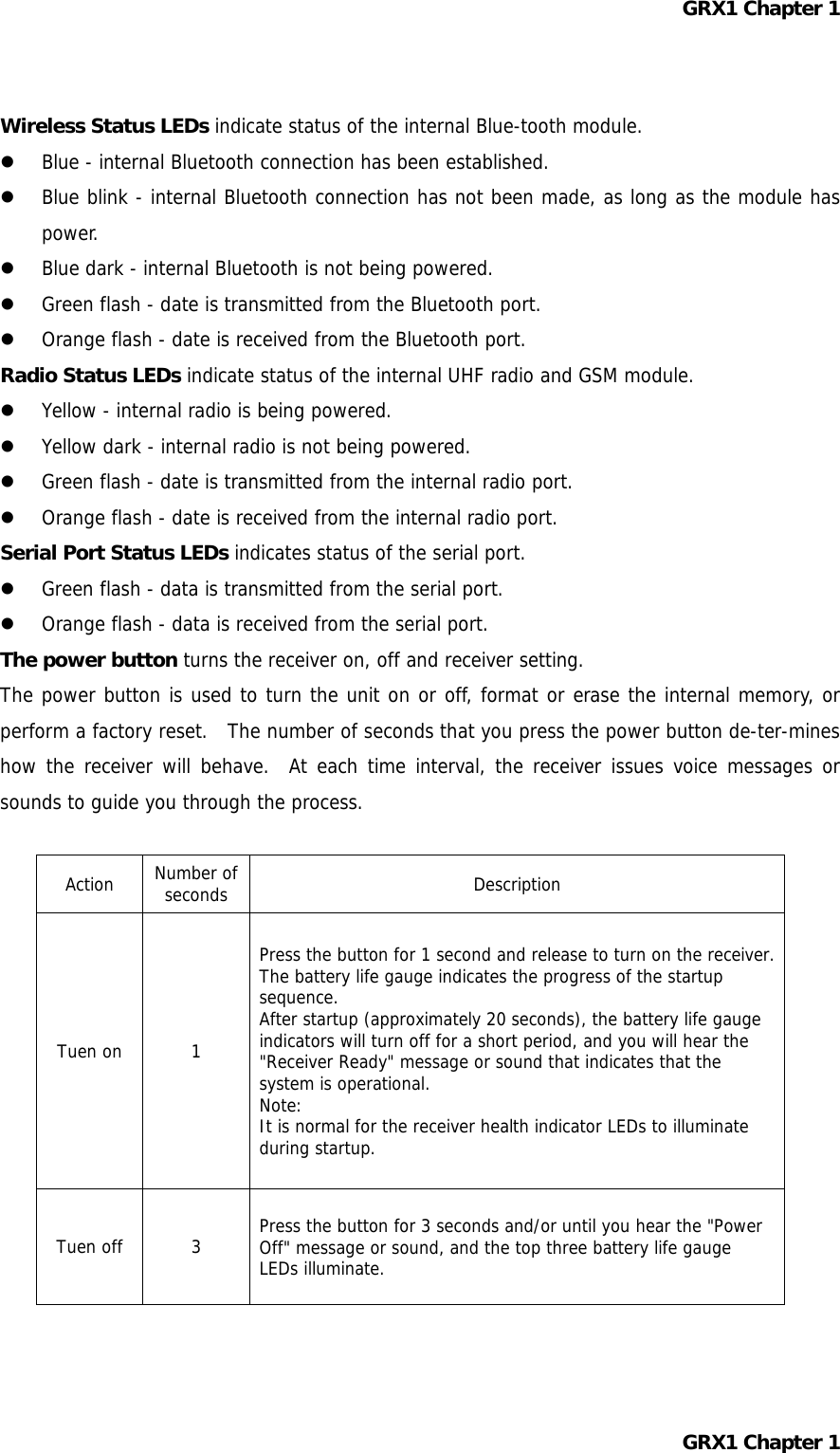
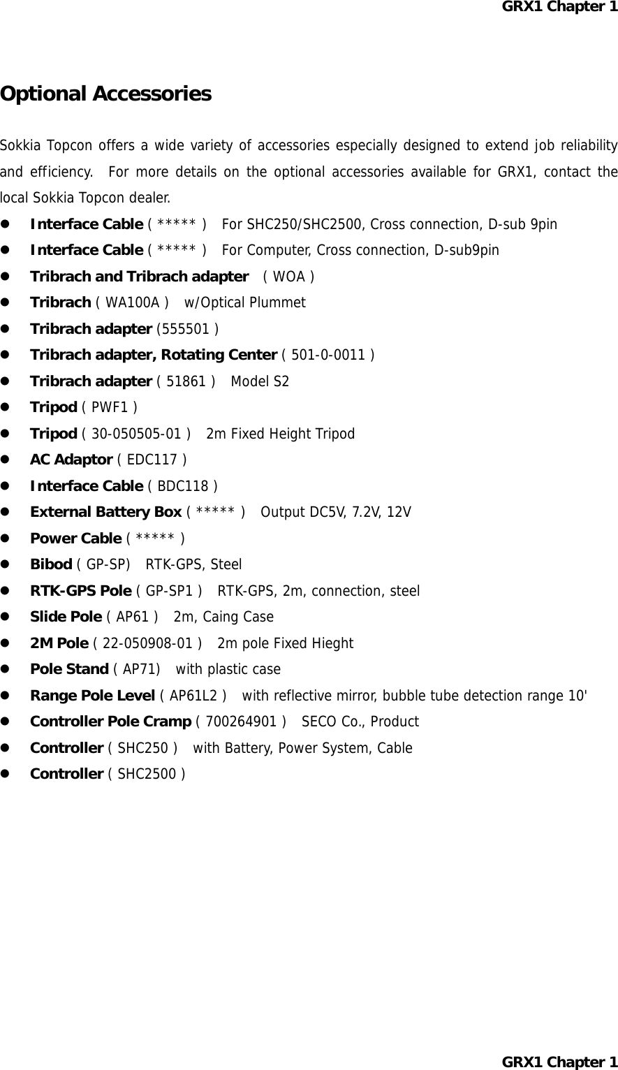
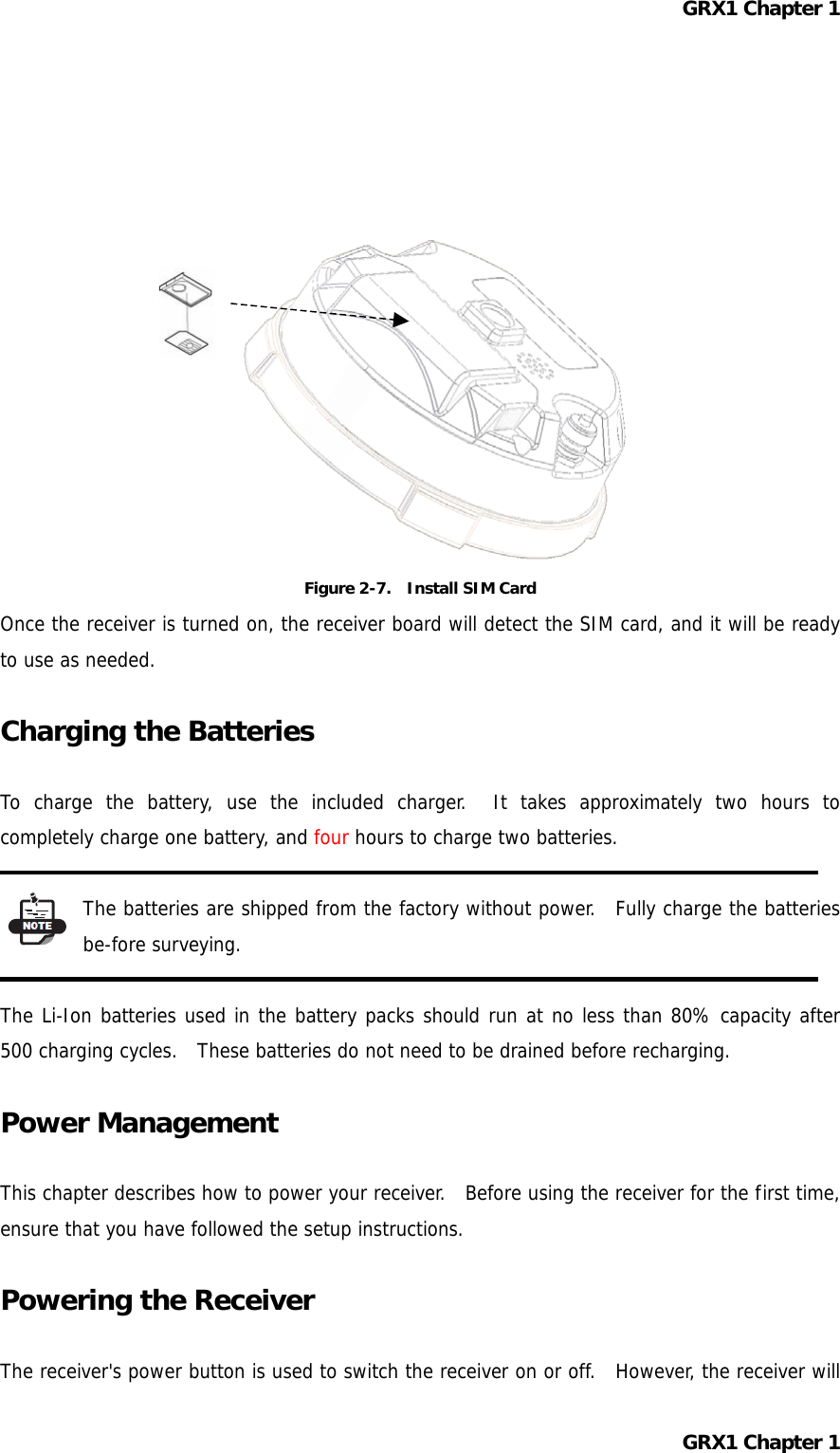
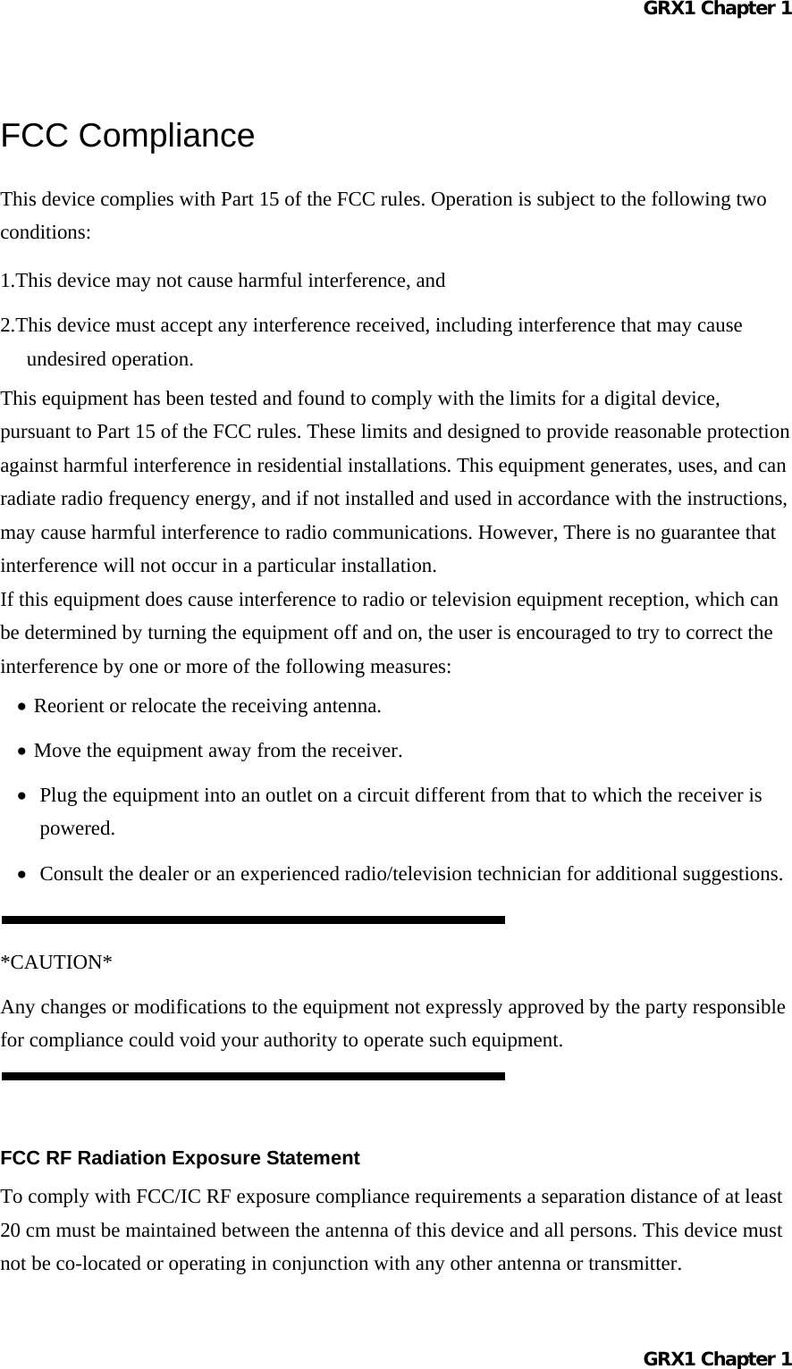
![GRX1 Chapter 1 Cables The GRX1 package includes standard communication cables for configuring the receiver. Table 1-3 lists the cables included in the GRX1 package. Table 1 -3. GRX1 Package Cables Cable Description Cable Illustration Serial Cable Connects the receiver to an external device ( controller or computer data transfer and receiver configuration. Body of connector back. p/n xx-xxxxxx-xx Other Accessories Battery ( BDC58 ) Li-ion Battery [ 4300mAh,7.2V DC ]. Power system - without Power Cable ( CDC68 ) Battery BDC58 [ about 150min ] × 2、AC100V [ without AC power cable、CDC68-11 include ] Power Cable ( EDC113/A/B/C/D/E ) CDC68 to AC consent. It is chosen by every country. Quick release ( 086-0-0001 ) Measuring Tape ( 405-0-0013 ) 3.7m HI ( Calibrated ) SD Card FAT16、2GB industrial CD-ROM include Manual PDF and Config Tool Carrying Case For more details on the accessories and package options available for the GRX1, contact the local Sokkia Topcon dealer. GRX1 Chapter 1](https://usermanual.wiki/Topcon-America/090531.Manual-1/User-Guide-1291723-Page-12.png)
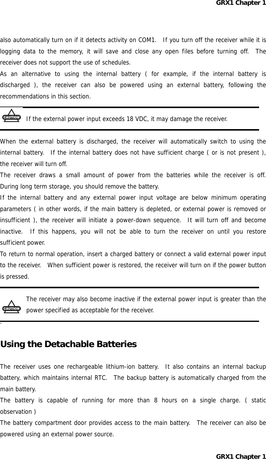
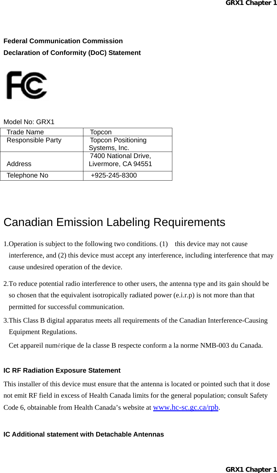
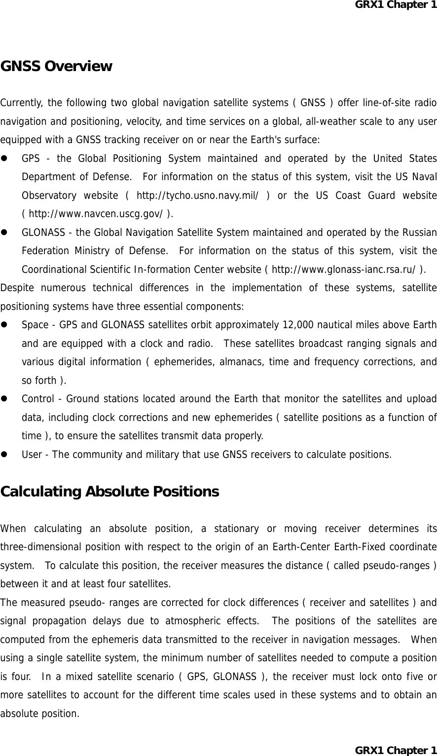
![GRX1 Chapter 1 Declaration of Conformity with Regard to the R&TTE Directive 1999/5/EC Česky [Czech] (Topcon Positioning Systems, Inc.) tímto prohlašuje, že tento (GRX1) je ve shodě se základními požadavky a dalšími příslušnými ustanoveními směrnice 1999/5/ES. Dansk [Danish] Undertegnede (Topcon Positioning Systems, Inc.) erklærer herved, at følgende udstyr (GRX1) overholder de væsentlige krav og øvrige relevante krav i direktiv 1999/5/EF. Deutsch [German] Hiermit erklärt (Topcon Positioning Systems, Inc.) dass sich das Gerät (GRX1) in Übereinstimmung mit den grundlegenden Anforderungen und den übrigen einschlägigen Bestimmungen der Richtlinie 1999/5/EG befindet. Eesti [Estonian] Käesolevaga kinnitab (Topcon Positioning Systems, Inc.) seadme (GRX1) vastavust direktiivi 1999/5/EÜ põhinõuetele ja nimetatud direktiivist tulenevatele teistele asjakohastele sätetele. English Hereby, (Topcon Positioning Systems, Inc.) declares that this (GRX1) is in compliance with the essential requirements and other relevant provisions of Directive 1999/5/EC. Español [Spanish] Por medio de la presente (Topcon Positioning Systems, Inc.) declara que el (GRX1) cumple con los requisitos esenciales y cualesquiera otras disposiciones aplicables o exigibles de la Directiva 1999/5/CE. Ελληνική [Greek] ΜΕ ΤΗΝ ΠΑΡΟΥΣΑ (Topcon Positioning Systems, Inc.) ΔΗΛΩΝΕΙ ΟΤΙ (GRX1) ΣΥΜΜΟΡΦΩΝΕΤΑΙ ΠΡΟΣ ΤΙΣ ΟΥΣΙΩΔΕΙΣ ΑΠΑΙΤΗΣΕΙΣ ΚΑΙ ΤΙΣ ΛΟΙΠΕΣ ΣΧΕΤΙΚΕΣ ΔΙΑΤΑΞΕΙΣ ΤΗΣ ΟΔΗΓΙΑΣ 1999/5/ΕΚ. Français [French] Par la présente (Topcon Positioning Systems, Inc.) déclare que l'appareil (GRX1) est conforme aux exigences essentielles et aux autres dispositions pertinentes de la directive 1999/5/CE. Italiano [Italian] Con la presente (Topcon Positioning Systems, Inc.) dichiara che questo (GRX1) è conforme ai requisiti essenziali ed alle altre disposizioni pertinenti stabilite dalla direttiva 1999/5/CE. Ar šo (Topcon Positioning Systems, Inc.) deklarē, Latviski GRX1 Chapter 1](https://usermanual.wiki/Topcon-America/090531.Manual-1/User-Guide-1291723-Page-28.png)
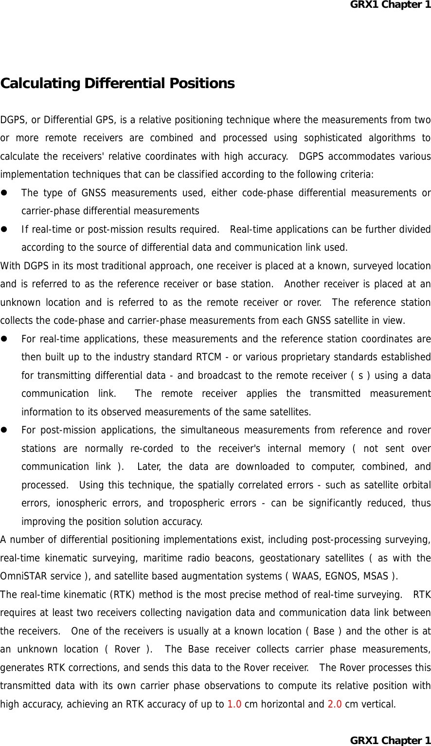
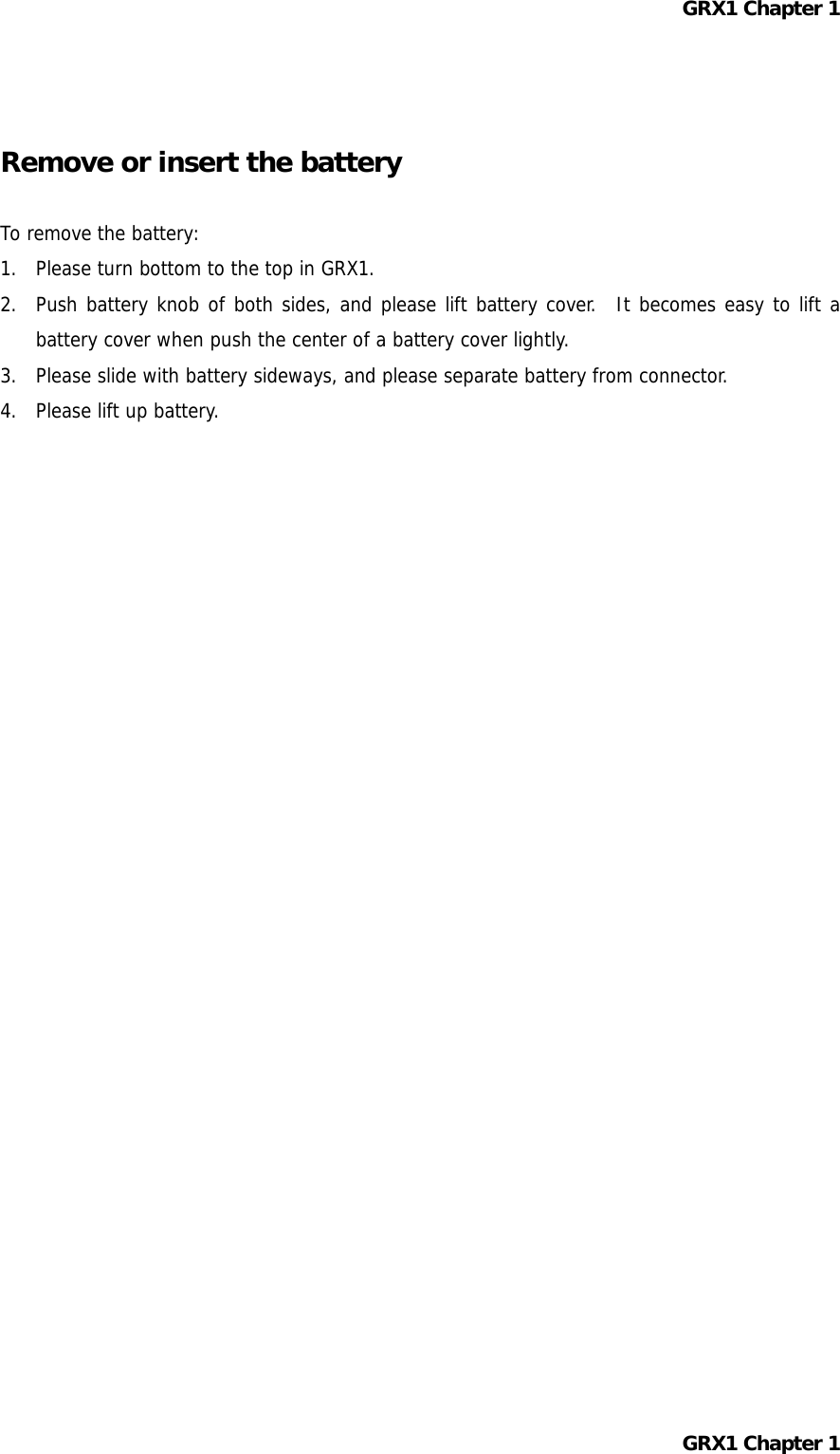
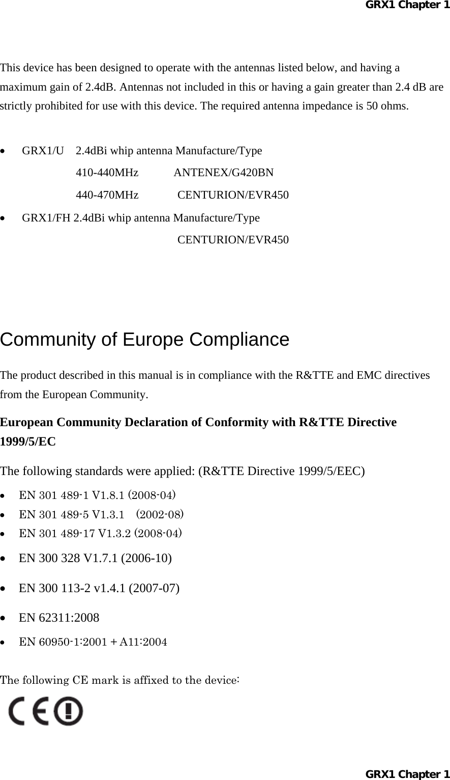
![GRX1 Chapter 1 [Latvian] ka (GRX1) atbilst Direktīvas 1999/5/EK būtiskajām prasībām un citiem ar to saistītajiem noteikumiem. Šiuo (Topcon Positioning Systems, Inc.) deklaruoja, kad šis (GRX1) atitinka esminius reikalavimus ir kitas 1999/5/EB Direktyvos nuostatas. Lietuvių [Lithuanian] Hierbij verklaart (Topcon Positioning Systems, Inc.) dat het toestel (GRX1) in overeenstemming is met de essentiële eisen en de andere relevante bepalingen van richtlijn 1999/5/EG. Nederlands [Dutch] Hawnhekk, (Topcon Positioning Systems, Inc.) , jiddikjara li dan (GRX1) jikkonforma mal-ħtiġijiet essenzjali u ma provvedimenti oħrajn relevanti li hemm fid-Dirrettiva 1999/5/EC. Malti [Maltese] Alulírott, (Topcon Positioning Systems, Inc.) nyilatkozom, hogy a (GRX1) megfelel a vonatkozó alapvetõ követelményeknek és az 1999/5/EC irányelv egyéb elõírásainak. Magyar [Hungarian] Niniejszym, (Topcon Positioning Systems, Inc.) , deklaruję, że (GRX1) spełnia wymagania zasadnicze oraz stosowne postanowienia zawarte Dyrektywie 1999/5/EC. Polski [Polish] (Topcon Positioning Systems, Inc.) declara que este (GRX1) está conforme com os requisitos essenciais e outras disposições da Directiva 1999/5/CE. Português [Portuguese] (Topcon Positioning Systems, Inc.) izjavlja, da je ta (GRX1) v skladu z bistvenimi zahtevami in ostalimi relevantnimi določili direktive 1999/5/ES. Slovensko [Slovenian] (Topcon Positioning Systems, Inc.) týmto vyhlasuje, že (GRX1) spĺňa základné požiadavky a všetky príslušné ustanovenia Smernice 1999/5/ES. Slovensky [Slovak] (Topcon Positioning Systems, Inc.) vakuuttaa täten että (GRX1) tyyppinen laite on direktiivin 1999/5/EY oleellisten vaatimusten ja sitä koskevien direktiivin muiden ehtojen mukainen. Suomi [Finnish] Härmed intygar (Topcon Positioning Systems, Inc.) att denna (GRX1) står I överensstämmelse med de väsentliga egenskapskrav och övriga relevanta bestämmelser som framgår av direktiv 1999/5/EG. Svenska [Swedish] GRX1 Chapter 1](https://usermanual.wiki/Topcon-America/090531.Manual-1/User-Guide-1291723-Page-29.png)