Topcon America 090531 GNSS Receiver User Manual Introduction
Topcon America Corporation GNSS Receiver Introduction
Contents
- 1. Manual 1
- 2. Manual 2
Manual 1
GRX1 Chapter 1
Introduction
The GRX1 receiver is a multi-frequency, GPS+ receiver built to be the most advanced and
compact receiver for the surveying market. The receiver is a multi-function, multi-purpose
receiver intended for precision markets.
Precision markets means markets for equipment, subsystems, components and software for
surveying, construction, commercial mapping, civil engineering, precision agriculture and
land-based construction and agriculture machine control, photogrammetry mapping,
hydrographic and any use reasonably related to the foregoing.
The GRX1 can receive and processes multiple signal types ( including the latest GPS L1, L2, C/A,
L2C GLONASS L1, L2, C/A signals ) improving the accuracy and reliability of the survey points
and positions, especially under difficult jobsite conditions. The multifrequency and GPS+
features of the receiver combine to provide a positioning system accurate for any survey.
Several other features, including multipath mitigation, provide under-canopy and low signal
strength reception. The receiver provides the functionality, accuracy, availability, and integrity
needed for fast and easy data collection.
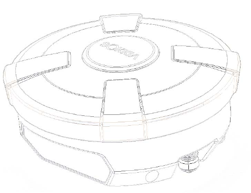
Figure 1-1. GRX1 Receiver
Principles of Operation
Surveying with the right GPS receiver can provide users accurate and precise positioning, a
requirement for any surveying project. This section gives an overview of existing and
proposed Global Navigation Satellite Systems ( GNSS ) and receiver functions so that basic
operating principles can be applied.
GRX1 Chapter 1
GRX1 Chapter 1
GNSS Overview
Currently, the following two global navigation satellite systems ( GNSS ) offer line-of-site radio
navigation and positioning, velocity, and time services on a global, all-weather scale to any user
equipped with a GNSS tracking receiver on or near the Earth's surface:
GPS - the Global Positioning System maintained and operated by the United States
Department of Defense. For information on the status of this system, visit the US Naval
Observatory website ( http://tycho.usno.navy.mil/ ) or the US Coast Guard website
( http://www.navcen.uscg.gov/ ).
GLONASS - the Global Navigation Satellite System maintained and operated by the Russian
Federation Ministry of Defense. For information on the status of this system, visit the
Coordinational Scientific In-formation Center website ( http://www.glonass-ianc.rsa.ru/ ).
Despite numerous technical differences in the implementation of these systems, satellite
positioning systems have three essential components:
Space - GPS and GLONASS satellites orbit approximately 12,000 nautical miles above Earth
and are equipped with a clock and radio. These satellites broadcast ranging signals and
various digital information ( ephemerides, almanacs, time and frequency corrections, and
so forth ).
Control - Ground stations located around the Earth that monitor the satellites and upload
data, including clock corrections and new ephemerides ( satellite positions as a function of
time ), to ensure the satellites transmit data properly.
User - The community and military that use GNSS receivers to calculate positions.
Calculating Absolute Positions
When calculating an absolute position, a stationary or moving receiver determines its
three-dimensional position with respect to the origin of an Earth-Center Earth-Fixed coordinate
system. To calculate this position, the receiver measures the distance ( called pseudo-ranges )
between it and at least four satellites.
The measured pseudo- ranges are corrected for clock differences ( receiver and satellites ) and
signal propagation delays due to atmospheric effects. The positions of the satellites are
computed from the ephemeris data transmitted to the receiver in navigation messages. When
using a single satellite system, the minimum number of satellites needed to compute a position
is four. In a mixed satellite scenario ( GPS, GLONASS ), the receiver must lock onto five or
more satellites to account for the different time scales used in these systems and to obtain an
absolute position.
GRX1 Chapter 1
GRX1 Chapter 1
Calculating Differential Positions
DGPS, or Differential GPS, is a relative positioning technique where the measurements from two
or more remote receivers are combined and processed using sophisticated algorithms to
calculate the receivers' relative coordinates with high accuracy. DGPS accommodates various
implementation techniques that can be classified according to the following criteria:
The type of GNSS measurements used, either code-phase differential measurements or
carrier-phase differential measurements
If real-time or post-mission results required. Real-time applications can be further divided
according to the source of differential data and communication link used.
With DGPS in its most traditional approach, one receiver is placed at a known, surveyed location
and is referred to as the reference receiver or base station. Another receiver is placed at an
unknown location and is referred to as the remote receiver or rover. The reference station
collects the code-phase and carrier-phase measurements from each GNSS satellite in view.
For real-time applications, these measurements and the reference station coordinates are
then built up to the industry standard RTCM - or various proprietary standards established
for transmitting differential data - and broadcast to the remote receiver ( s ) using a data
communication link. The remote receiver applies the transmitted measurement
information to its observed measurements of the same satellites.
For post-mission applications, the simultaneous measurements from reference and rover
stations are normally re-corded to the receiver's internal memory ( not sent over
communication link ). Later, the data are downloaded to computer, combined, and
processed. Using this technique, the spatially correlated errors - such as satellite orbital
errors, ionospheric errors, and tropospheric errors - can be significantly reduced, thus
improving the position solution accuracy.
A number of differential positioning implementations exist, including post-processing surveying,
real-time kinematic surveying, maritime radio beacons, geostationary satellites ( as with the
OmniSTAR service ), and satellite based augmentation systems ( WAAS, EGNOS, MSAS ).
The real-time kinematic (RTK) method is the most precise method of real-time surveying. RTK
requires at least two receivers collecting navigation data and communication data link between
the receivers. One of the receivers is usually at a known location ( Base ) and the other is at
an unknown location ( Rover ). The Base receiver collects carrier phase measurements,
generates RTK corrections, and sends this data to the Rover receiver. The Rover processes this
transmitted data with its own carrier phase observations to compute its relative position with
high accuracy, achieving an RTK accuracy of up to 1.0 cm horizontal and 2.0 cm vertical.
GRX1 Chapter 1
GRX1 Chapter 1
Essential Components for Quality Surveying
Achieving quality position results requires the following elements:
Accuracy - The accuracy of a position primarily depends upon the satellite geometry
( Geometric Dilution of Precision, or GDOP ) and the measurement (ranging) errors.
Differential positioning ( DGPS and RTK ) strongly mitigates atmospheric and orbital
errors, and counteracts Selective Availability ( SA ) signals the US Department of
Defense transmits with GPS signals.
The more satellites in view, the stronger the signal, the lower the DOP number, the
higher positioning accuracy.
Availability - The availability of satellites affects the calculation of valid positions. The
more visible satellites available, the more valid and accurate the position. Natural and
man-made objects can block, interrupt, and distort signals, lowering the number of
available satellites and adversely affecting signal reception.
Integrity - Fault tolerance allows a position to have greater integrity, increasing accuracy.
Several factors combine to provide fault tolerance, including:
Receiver Autonomous Integrity Monitoring ( RAIM ) detects faulty GNSS satellites and
removes them from the position calculation.
Five or more visible satellites for only GPS or only GLONASS; six or more satellites
for mixed scenario
Satellite Based Augmentation Systems ( WAAS, EGNOS, and so on ) creates and
transmit, along with DGPS corrections, data integrity information ( for example,
satellite health warnings ).
Current ephemerides and almanacs.
Conclusion
This overview simply outlines the basics of satellite positioning. For more detailed information,
visit the Sokkia Topcon website.
Receiver Overview
When power is turned on and the receiver self-test completes, the receiver's 72 channels
initialize and begin tracking visible satellites. Each of the receiver's channels can be used to
track any one of the GPS or GALILEO signals. The number of channels available allows the
receiver to track all visible global positioning satellites at any time and location.
GRX1 Chapter 1
GRX1 Chapter 1
An internal GPS+ antenna equipped with a low noise amplifier ( LNA ) and the receiver's radio
frequency ( RF ) device are connected with a co-axial cable. The wide-band signal received is
down-converted, filtered, digitized, and assigned to different channels. The receiver processor
controls the process of signal tracking.
Once the signal is locked in the channel, it is demodulated and necessary signal parameters
( carrier and code phases ) are measured. Also, broadcast navigation data are retrieved from
the navigation frame.
After the receiver locks on to four or more satellites, its absolute position in WGS-84 and the
time offset between the receiver clock and GPS time are computed. This information and the
measurement data can be stored in the optional SD card and downloaded later onto a computer,
then processed using a post-processing software package. When the receiver operates in RTK
mode, raw data measurements can also be recorded into the receiver's internal memory. This
allows the operator to double check real-time results obtained in the field.
Depending on your options, capabilities of the receiver include:
Satellite based augmentation systems ( WAAS, EGNOS, and so forth ).
Adjustable phase locked loop ( PLL ) and delay lock loop ( DLL ) parameters
Dual- or multi-frequency modes, including static, kinematic, real-time kinematic ( RTK ),
and differential GPS ( DGPS ) survey modes ( DGPS modes include static, kinematic, and
RTK )
Auto data logging
Setting different mask angles
Setting different survey parameters
Static or dynamic modes
Getting Acquainted
The GRX1 is a 72-channel GPS receiver, which includes the following:
External, detachable batteries
One data ports
Interface for controlling and viewing data logging
External memory card slot
Internal radio modem
Bluetooth wireless technology module
Optional GSM/GPRS module
Optional CDMA module ( only with the Digital UHF radio modem )
GRX1 Chapter 1
GRX1 Chapter 1
Batteries
The GRX1 receiver comes equipped with one detachable, re-chargeable batteries ( Figure 1-2 )
for powering the receiver.
Figure 1-2. GRX1 Batteries
Please use CDC68 as battery charging cradle.
It takes approximately four hours to completely charge one battery, and eight hours to charge
two batteries. ( In BDC58 use )
GRX1 Receiver
The GRX1 receiver's advanced design reduces the number of cables required for operation,
allowing for more reliable and efficient surveying. The casing allocates space for one
removable, rechargeable batteries, SD and SIM card slots, a Bluetooth wireless technology
module and a radio modem communications board.
The GRX1 comes in one of the following configura-tions:
with an FH915 Plus TX/RX/RP radio modem and a GSM/GPRS module
with a 1W Digital UHF TX/RX radio modem, depending on the country
with a Digital UHF radio modem and a GSM/GPRS module
with a Digital UHF TX/RX radio modem and a CDMA module
Other features include one data ports, a power port, and a MINTER for viewing status and
controlling data input/output.
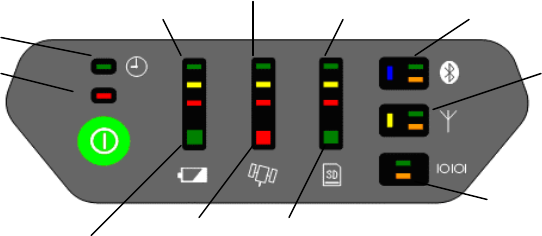
MINTER
The MINTER is the receiver's minimum interface used to dis-play and control data input and
GRX1 Chapter 1
GRX1 Chapter 1
output ( Figure 1-5 ).
Figure 1-5. GRX1 MINTER
Serial Port Status
Radio Status
Battery Status Position Status
Scheduler
A
vailable Power Bar
Satellite Tracking Bar
Memory Capacity Bar
Receiver Health
Wireless Status
File Statius
Available Power Bar indicates battery remaining or voltage.
Green - indicate greater than 50%.
Yellow - indicate greater than 25%.
Red - indicate greater than 10%.
Red blink - indicate less than 10%.
Battery Status LEDs indicates an available battery and the usage condition.
Green - only battery is available.
Red - only external power is available.
Umber - battery and external power are available.
Satellite Tracking Bar indicate number of satellites tracked.
Green - indicate greater than 8 satellites.
Yellow - indicate 6 or 7 satellites.
Red - indicate 4 or 5 satellites.
Red blink - indicate 3, 2, 1 or 0 satellites.
Position Status LEDs indicate current type position computed.
Green - Integer RTK or Fixed RTK.
Umber - DGPS or Float RTK.
Red - Single
Memory Capacity Bar indicate a percentage of available space in the memory.
Green - indicate greater than 50%.
Yellow - indicate greater than 25%.
Red - indicate greater than 10%.
Red blink - indicate greater than 0%.
File Status LEDs indicate status of current file.
Green - file is opened.
Umber blink - writing are done on the file.
( light out ) - file is not opened or there is no memory card in slot.
GRX1 Chapter 1

GRX1 Chapter 1
Wireless Status LEDs indicate status of the internal Blue-tooth module.
Blue - internal Bluetooth connection has been established.
Blue blink - internal Bluetooth connection has not been made, as long as the module has
power.
Blue dark - internal Bluetooth is not being powered.
Green flash - date is transmitted from the Bluetooth port.
Orange flash - date is received from the Bluetooth port.
Radio Status LEDs indicate status of the internal UHF radio and GSM module.
Yellow - internal radio is being powered.
Yellow dark - internal radio is not being powered.
Green flash - date is transmitted from the internal radio port.
Orange flash - date is received from the internal radio port.
Serial Port Status LEDs indicates status of the serial port.
Green flash - data is transmitted from the serial port.
Orange flash - data is received from the serial port.
The power button turns the receiver on, off and receiver setting.
The power button is used to turn the unit on or off, format or erase the internal memory, or
perform a factory reset. The number of seconds that you press the power button de-ter-mines
how the receiver will behave. At each time interval, the receiver issues voice messages or
sounds to guide you through the process.
Action Number of
seconds Description
Tuen on 1
Press the button for 1 second and release to turn on the receiver.
The battery life gauge indicates the progress of the startup
sequence.
After startup (approximately 20 seconds), the battery life gauge
indicators will turn off for a short period, and you will hear the
"Receiver Ready" message or sound that indicates that the
system is operational.
Note:
It is normal for the receiver health indicator LEDs to illuminate
during startup.
Tuen off 3 Press the button for 3 seconds and/or until you hear the "Power
Off" message or sound, and the top three battery life gauge
LEDs illuminate.
GRX1 Chapter 1
GRX1 Chapter 1
Factory
reset 10
With the receiver on, press the button for 1 0 seconds until you
hear the "Factory Reset" message or sound and the top three
LEDs on the battery life, satellite tracking, and memory gauges
illuminate.
Release the button to reset all stored parameters on the receiver
to their default values.
Note:
This action is irreversible.
Erase
memory 20
With the receiver on, press the button for 20 seconds until you
hear the "Delete Files" message or sound and the top three LEDs
on the memory gauge illuminate.
Release the button to delete all the files from the memory.
Note:
This action is irreversible.
If you are unsure about whether you want to delete all the files,
hold the button longer than 25 seconds, so that the receiver
simply returns to normal operation.
To delete individual files from the memory, use a data collector
or SOKKIA TOPCON software on your PC.
Disregard 25
When you hold the button longer than 25 seconds and you hear
the "Continue Operation" message or sound, no action will be
taken, and the receiver will return to normal operation.
The receiver will not turn off, the data files will not be erased,
and the settings will not revert to factory settings.
Data and Power Ports
The GRX1 has the following three ports (Figure 1-6):
Serial - rimmed in blue; used for communication between the receiver and an external
device. The body of the connector on the corresponding cable is blue.
Power - rimmed in red; used to connect the receiver to an external power source. The
body of the connector on the corresponding cable is red.
Figure 1-6. GRX1 Ports
GRX1 Chapter 1
GRX1 Chapter 1
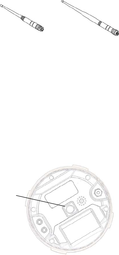
External Radio Antenna Connector
The UHF and SS antennas connect to the external antenna connector under the GRX1 housing
( Figure 1-7 ). Both modem antenna types include support for a GSM modem.
The modem antenna depends on the type of modem in-stalled in the receiver:
UHF: Uses a BNC RF connection and comes in three versions: 410-440MHz ( p/n
30-070003-01 ) and 440-470MHz ( p/n 30-050503-01 ).
Spread Spectrum: Uses a reverse polarity TNC RF connection and comes in one version:
( p/n 30-030012-01 ).
Figure 1-7. Modem Antennas
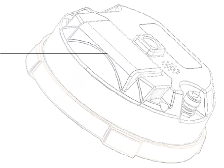
Connector
The bottom connector ( Figure 1-8 ) connects the receiver to either a standard 5/8''thread
pole/adapter or the quick disconnect ( see "The quick disconnect adapter" on page 1-22 for
details ).
Bottom Connector
for Standard Setups
Figure 1-8. GRX1 Quick Connector
GRX1 Chapter 1
GRX1 Chapter 1
SD/MMC and SIM Card Slots
The SD and SIM card slots reside under the batteries near the base of the dome.
The SD card slot is located to the left of the MINTER inside the battery pocket ( Figure 1-9 )
and connects an optional SD card to the receiver board to provide memory. Once installed, the
SD card usually remains inside the receiver. The data that resides on the SD card can be
accessed via the serial port, or Bluetooth wireless technology. A secure digital card can be
purchased at a local computer supply store.
The SIM card slot is located to the inside the battery pocket and allows a standard SIM card
to be installed in the receiver. Once installed, the SIM card provides a unique identification for
the receiver's GSM module and enables the receiver's GSM functionality based on the
subscribed ser-vices ( the receiver board accesses the GSM module which accesses the SIM
card ). The SIM card usually remains inside the receiver. The GSM module with the SIM card
installed can be accessed via Modem-TPS for configuration purposes. A SIM card can be
purchased from a local cellular provider.
Card Slot
SD and SIM
Figure 1-9. GRX1 Card Slot Example
GRX1 Chapter 1
GRX1 Chapter 1
Cables
The GRX1 package includes standard communication cables for configuring the receiver. Table
1-3 lists the cables included in the GRX1 package.
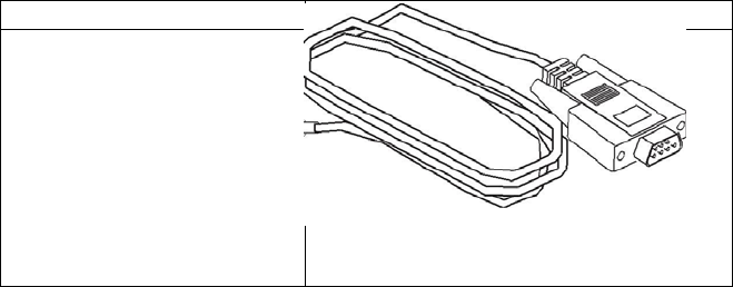
Table 1 -3. GRX1 Package Cables
Cable Description Cable Illustration
Serial Cable
Connects the receiver to an
external device ( controller
or computer data transfer
and receiver configuration.
Body of connector back.
p/n xx-xxxxxx-xx
Other Accessories
Battery ( BDC58 ) Li-ion Battery [ 4300mAh,7.2V DC ].
Power system - without Power Cable ( CDC68 ) Battery BDC58 [ about 150min ] ×
2、AC100V [ without AC power cable、CDC68-11 include ]
Power Cable ( EDC113/A/B/C/D/E ) CDC68 to AC consent. It is chosen by every
country.
Quick release ( 086-0-0001 )
Measuring Tape ( 405-0-0013 ) 3.7m HI ( Calibrated )
SD Card FAT16、2GB industrial
CD-ROM include Manual PDF and Config Tool
Carrying Case
For more details on the accessories and package options available for the GRX1, contact the
local Sokkia Topcon dealer.
GRX1 Chapter 1
GRX1 Chapter 1
Optional Accessories
Sokkia Topcon offers a wide variety of accessories especially designed to extend job reliability
and efficiency. For more details on the optional accessories available for GRX1, contact the
local Sokkia Topcon dealer.
Interface Cable ( ***** ) For SHC250/SHC2500, Cross connection, D-sub 9pin
Interface Cable ( ***** ) For Computer, Cross connection, D-sub9pin
Tribrach and Tribrach adapter ( WOA )
Tribrach ( WA100A ) w/Optical Plummet
Tribrach adapter (555501 )
Tribrach adapter, Rotating Center ( 501-0-0011 )
Tribrach adapter ( 51861 ) Model S2
Tripod ( PWF1 )
Tripod ( 30-050505-01 ) 2m Fixed Height Tripod
AC Adaptor ( EDC117 )
Interface Cable ( BDC118 )
External Battery Box ( ***** ) Output DC5V, 7.2V, 12V
Power Cable ( ***** )
Bibod ( GP-SP) RTK-GPS, Steel
RTK-GPS Pole ( GP-SP1 ) RTK-GPS, 2m, connection, steel
Slide Pole ( AP61 ) 2m, Caing Case
2M Pole ( 22-050908-01 ) 2m pole Fixed Hieght
Pole Stand ( AP71) with plastic case
Range Pole Level ( AP61L2 ) with reflective mirror, bubble tube detection range 10'
Controller Pole Cramp ( 700264901 ) SECO Co., Product
Controller ( SHC250 ) with Battery, Power System, Cable
Controller ( SHC2500 )
GRX1 Chapter 1
GRX1 Chapter 1
Option Authorization File (OAF)
Sokkia Topcon issues an Option Authorization File ( OAF ) to enable the specific options that
customers purchase. An Option Authorization File allows customers to customize and
configure the receiver according to particular needs, thus only purchasing those options
needed.
Typically, all receivers ship with a temporary OAF that allows it to be used for a predetermined
period of time. When the receiver is purchased, a new OAF permanently activates purchased
options. Receiver options remain intact when clearing the NVRAM or resetting the receiver.
The OAF enables the following kinds of functions. For a complete list of available options and
details, visit the Sokkia Topcon website or consult a Sokkia Topcon dealer.
Type of signal ( standard L1; optional L2, L5 GPS, GLONASS )
Update rate standard 1Hz ( optional 5, 10, or 20Hz )
RTK at 1Hz, 5Hz, 10Hz, and 20Hz
RTCM/CMRInput/Output
Advanced multipath reduction
Wide Area Augmentation System ( WAAS )
Receiver Autonomous Integrity Monitoring ( RAIM )
GRX1 Chapter 1
GRX1 Chapter 1
Pre-survey Preparation
Before beginning to survey with the GRX1 receiver, the follow-ing software needs to be installed
and configurations need to be applied:
Install receiver configuration software See
"Installing Sokkia Topcon Software" on page 2-2.
Optional: install SD card and/or SIM card
See "Installing the Optional SD and SIM Cards" on page
2-7. Charge the batteries
See "Charging the Batteries" on page 2-9.
Enable power source settings ( either attached or external )
See "Power Management" on page 2-11 and "Power-ing the Receiver" on page 2-14.
Configure the Bluetooth wireless technology module
See "Bluetooth Module Configuration" on page 2-23.
Collect almanacs and ephemerides ( after first-time configuration activities as described in
Chapter 3 )
See "Collecting Almanacs and Ephemerides" on page 2-26.
This chapter also discusses connecting batteries to the receiver, connecting the receiver and a
computer, and powering the receiver using different sources.
Installing Sokkia Topcon Software
The Sokkia Topcon GPS+ CD includes the following software programs used for configuring and
maintaining the receiver. This soft-ware is also available on the Sokkia Topcon website to
registered users.
PC-CDU Lite ver. 2.1.15 or newer
Modem-TPS ver. 2.2p2 or newer
BTCONF ver. 1.3 or newer
FLoader ver 1.0.07 or newer
If installing the program ( s ) from the GPS+ CD, insert the CD into the computer's CD-ROM
drive.
If downloading the program ( s ) from the website, extract the program's files into a folder on
the hard drive.
The following sections describe installing this software, and other sections throughout the
manual describe using this software with the receiver.
GRX1 Chapter 1
GRX1 Chapter 1
Installing PC-CDU
PC-CDU is a comprehensive Windows software product designed for controlling GPS+ receivers
developed by Sokkia Topcon. PC-CDU uses the GPS Receiver Interface Language ( GRIL ) to
configure various receiver settings and diagnose receiver performance.
The PC-CDU software exists in two versions: a full-functionality version called PC-CDU MS and
a reduced-functionality version called PC-CDU Lite. PC-CDU Lite is available for free on the
Sokkia Topcon website ( www.sokkia.co.jp ) or the GPS+ CD.
Computer requirements for PC-CDU are: Windows98 or newer and an RS-232C or Bluetooth
capable. Use PC-CDU version 2.1.15 or newer to correctly configure the receiver.
Refer to the PC-CDU Reference Manual for full details on installing and using PC-CDU.
To Install PC-CDU:
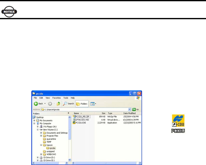
1. Create a PC-CDU folder on the hard drive, and place the compressed PC-CDU zip file
( retrieved from either the website or the GPS+ CD ) in this folder.
2. Navigate to the PC-CDU folder, and double-click the PC-CDU_MS zip file.
3. Extract the PCCDU.EXE and associated *.dll file to the PC-CDU folder ( Figure 2-1 ).
4. Optionally, create a shortcut on the computer's desktop for quick access to PC-CDU ( Figure
2-1 ).
Figure 2-1. Extract Program and Create Shortcut
To uninstall PC-CDU, navigate to the location of the *.exe file. Select the file, and press
Delete.
Installing Modem-TPS
Modem-TPS is a configuration program for the radio modem board inside the receiver.
GRX1 Chapter 1
GRX1 Chapter 1
Modem-TPS is available from the Sokkia Topcon website ( www.sokkia.co.jp ) or on the GPS+
CD.
Computer requirements for Modem-TPS are: Windows98 or newer and an RS-232C port or
Bluetooth wireless technology. Use Modem- TPS version 2.2p2 or newer to correctly configure
the receiver.
To install Modem-TPS:
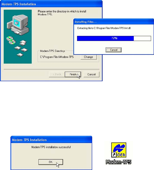
1. Navigate to the location of the Modem-TPS program, and double-click the Setup.exe icon.
2. Keep the default installation location or select a new location. Click Finish ( Figure 2-2 ).
Figure 2-2. Select Modem-TPS Installation Location and Install
3. Click OK to complete the installation ( Figure 2-3 ).
4. Optionally, create a shortcut on the computer's desktop for quick access to Modem-TPS
( Figure 2-3 )
Figure 2-3. Installation Complete and Shortcut
To uninstall Modem-TPS, use the Start menu on the computer:
1. Click Start Programs Modem-TPS UninstallModem-TPS, and click Yes at the prompt.
2. Click OK when the uninstall completes.
Installing BTCONF
BTCONF is a configuration program for the Bluetooth wireless technology module inside the
receiver. BTCONF is available from the Sokkia Topcon website ( www.sokkia.co.jp ) or on the
GPS+ CD.
Computer requirements for BTCONF are: Windows98 or newer and an RS-232C port or
GRX1 Chapter 1
GRX1 Chapter 1
Bluetooth wireless technology. Use BTCONF version 1.3 or newer to correctly configure the
receiver.
To install BTCONF:
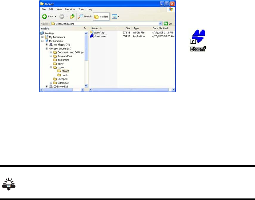
1. Create a BTCONF folder on the hard drive, and place the compressed BTCONF zip file
( retrieved from either the website or the GPS+ CD ) in this folder.
2. Navigate to the BTCONF folder, and double-click the BTCONF zip file.
3. Extract the btconf.exe to the BTCONF folder.
4. Create a shortcut on the computer's desktop for quick access to BTCONF ( Figure 2-4 ).
Figure 2-4. Extract Program and Create Shortcut
To uninstall BTCONF, navigate to the location of the *.exe file. Select the file, and press
Delete.
Each time BTCONF runs and configures the Bluetooth module, BTCONF saves the settings in a
file ( btconf.ini ). BTCONF automatically updates the file each time changes are made to the
Bluetooth module's settings.
To maintain unique Bluetooth module settings for different purposes, keep copies of
BTCONF in separate folders.
Installing FLoader
FLoader is a firmware loading program for the power board, GPS module, and modem board
inside the receiver. FLoader is available from the Sokkia Topcon website ( www.sokkia.co.jp )
or on the GPS+ CD.
Computer requirements for FLoader are: Windows98 or newer and an RS-232C port or
Bluetooth wireless technology. Use FLoader version 1.0.07 or newer to correctly configure the
receiver.
GRX1 Chapter 1
GRX1 Chapter 1
To install FLoader:
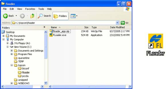
1. Create an FLoader folder on the hard drive and place the compressed FLoader zip file
( retrieved from either the website or the GPS+ CD ) in this folder.
2. Navigate to the FLoader folder, and double-click the zip file.
3. Extract the FLoader.exe file to the FLoader folder ( Figure 2-5 ).
4. Optionally, create a shortcut on the computer's desk-top for quick access to FLoader (Figure
2-5).
Figure 2-5. Extract Program and Create Shortcut
To uninstall FLoader, navigate to the location of the *.exe file, select the file, and press Delete
Installing the Optional SD and SIM Cards
Behind each detachable battery is a slot for the optional SD card or the optional SIM card. The
SD card provides memory space in which to save logged data; the SIM card provides
telephony communication for data transfer between two GSM-capable receivers. The SD card
can be purchased at a local computer store; the SIM card can be purchased at a local cellular
phone supply store. The receiver currently supports an SD card with up to 2GB ( FAT16
format ) capacity.
Once installed, the card ( s ) generally remains installed. The card can then be accessed via
the receiver board using a data port or Bluetooth wireless technology.
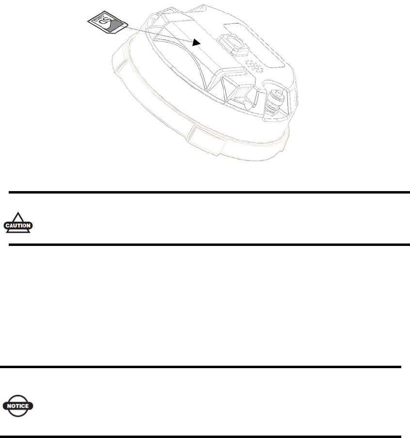
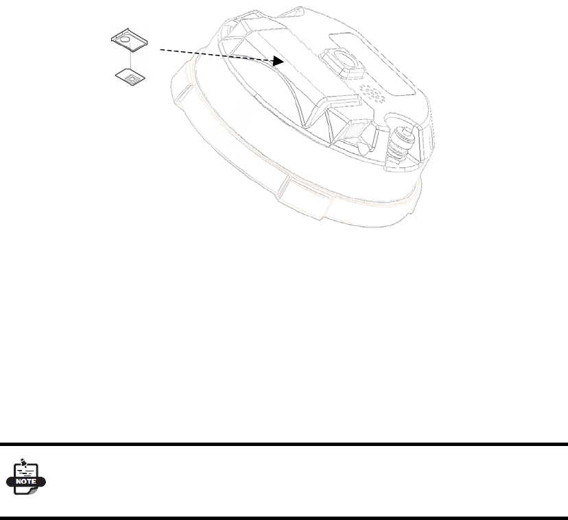
To install the SD card ( Figure 2-6 ):
1. Ensure the receiver is turned off.
2. Remove the battery.
3. Carefully insert the SD card, label side down, into the SD card slot located at the top of the
battery pocket.
GRX1 Chapter 1
GRX1 Chapter 1
Figure 2-6. Install SD Card
Do not remove the card if the receiver is powered on. Damage to data may result
from improper removal of the card.
Once the receiver is turned on, the receiver board will detect the SD card, and it will be ready
to use as needed.
To install the SIM card ( Figure 2-7 ):
The SIM card must support Circuit Switched Data to communicate directly between receivers.
The SIM card must have GPRS or EDGE support to communicate with a GPS Network IP
ad-dress.
For direct communication between Base and Rover receivers, you must install a SIM
card with a Circuit Switch Data plan and have subscriptions to the same service
provider for proper data communication.
1. Ensure the receiver is turned off.
2. Remove the battery.
3. If needed, snap the SIM card into its holder.
4. Carefully insert the holder, label side down, into the SIM card slot located at the top of the
battery pocket.
GRX1 Chapter 1
GRX1 Chapter 1
Figure 2-7. Install SIM Card
Once the receiver is turned on, the receiver board will detect the SIM card, and it will be ready
to use as needed.
Charging the Batteries
To charge the battery, use the included charger. It takes approximately two hours to
completely charge one battery, and four hours to charge two batteries.
The batteries are shipped from the factory without power. Fully charge the batteries
be-fore surveying.
The Li-Ion batteries used in the battery packs should run at no less than 80% capacity after
500 charging cycles. These batteries do not need to be drained before recharging.
Power Management
This chapter describes how to power your receiver. Before using the receiver for the first time,
ensure that you have followed the setup instructions.
Powering the Receiver
The receiver's power button is used to switch the receiver on or off. However, the receiver will
GRX1 Chapter 1

GRX1 Chapter 1
also automatically turn on if it detects activity on COM1. If you turn off the receiver while it is
logging data to the memory, it will save and close any open files before turning off. The
receiver does not support the use of schedules.
As an alternative to using the internal battery ( for example, if the internal battery is
discharged ), the receiver can also be powered using an external battery, following the
recommendations in this section.
If the external power input exceeds 18 VDC, it may damage the receiver.
When the external battery is discharged, the receiver will automatically switch to using the
internal battery. If the internal battery does not have sufficient charge ( or is not present ),
the receiver will turn off.
The receiver draws a small amount of power from the batteries while the receiver is off.
During long term storage, you should remove the battery.
If the internal battery and any external power input voltage are below minimum operating
parameters ( in other words, if the main battery is depleted, or external power is removed or
insufficient ), the receiver will initiate a power-down sequence. It will turn off and become
inactive. If this happens, you will not be able to turn the receiver on until you restore
sufficient power.
To return to normal operation, insert a charged battery or connect a valid external power input
to the receiver. When sufficient power is restored, the receiver will turn on if the power button
is pressed.
The receiver may also become inactive if the external power input is greater than the
power specified as acceptable for the receiver.
.
Using the Detachable Batteries
The receiver uses one rechargeable lithium-ion battery. It also contains an internal backup
battery, which maintains internal RTC. The backup battery is automatically charged from the
main battery.
The battery is capable of running for more than 8 hours on a single charge. ( static
observation )
The battery compartment door provides access to the main battery. The receiver can also be
powered using an external power source.
GRX1 Chapter 1
GRX1 Chapter 1
Remove or insert the battery
To remove the battery:
1. Please turn bottom to the top in GRX1.
2. Push battery knob of both sides, and please lift battery cover. It becomes easy to lift a
battery cover when push the center of a battery cover lightly.
3. Please slide with battery sideways, and please separate battery from connector.
4. Please lift up battery.
GRX1 Chapter 1

GRX1 Chapter 1
Regulatory Information
The following sections provide information on this product’s compliance with government
regulations for use.
UHF Radio Usage
*NOTICE*
Using a UHF radio requires a license. Operating a UHF radio without a license may result in
fines or other penalties. Be sure you comply with all local laws before operating a UHF radio.
Contact your local authorities (such as, the FCC in the United States) for details.
Surveying in RTK mode has made UHF the most popular choice for communications between
Base and Rover receivers. Know the strengths and weaknesses of this technology to get the best
use out of your receiver. The quality and strength of the UHF signals translates into range for
UHF communications.
1. The system’s range will greatly depend on the local conditions. Topography, local
communications and even meteorological conditions play a major role in the possible range
of RTK communications. If needed, use a scanner to find clear channels.
2. The system’s range will increase by adjusting the Base station’s antenna using the following
methods.
• Ensure the Base radio has a fully charged battery.
• Use directional antennas and/or repeaters to increase your system’s range. Directional
antennas concentrate the signal power within a more narrow direction, significantly
increasing the range of your system.
• Check the TPS accessory line for items to raise the Base radio.
GRX1 Chapter 1

GRX1 Chapter 1
FCC Compliance
This device complies with Part 15 of the FCC rules. Operation is subject to the following two
conditions:
1.This device may not cause harmful interference, and
2.This device must accept any interference received, including interference that may cause
undesired operation.
This equipment has been tested and found to comply with the limits for a digital device,
pursuant to Part 15 of the FCC rules. These limits and designed to provide reasonable protection
against harmful interference in residential installations. This equipment generates, uses, and can
radiate radio frequency energy, and if not installed and used in accordance with the instructions,
may cause harmful interference to radio communications. However, There is no guarantee that
interference will not occur in a particular installation.
If this equipment does cause interference to radio or television equipment reception, which can
be determined by turning the equipment off and on, the user is encouraged to try to correct the
interference by one or more of the following measures:
• Reorient or relocate the receiving antenna.
• Move the equipment away from the receiver.
• Plug the equipment into an outlet on a circuit different from that to which the receiver is
powered.
• Consult the dealer or an experienced radio/television technician for additional suggestions.
*CAUTION*
Any changes or modifications to the equipment not expressly approved by the party responsible
for compliance could void your authority to operate such equipment.
FCC RF Radiation Exposure Statement
To comply with FCC/IC RF exposure compliance requirements a separation distance of at least
20 cm must be maintained between the antenna of this device and all persons. This device must
not be co-located or operating in conjunction with any other antenna or transmitter.
GRX1 Chapter 1

GRX1 Chapter 1
Federal Communication Commission
Declaration of Conformity (DoC) Statement
Model No: GRX1
Trade Name Topcon
Responsible Party Topcon Positioning
Systems, Inc.
Address 7400 National Drive,
Livermore, CA 94551
Telephone No +925-245-8300
Canadian Emission Labeling Requirements
1.Operation is subject to the following two conditions. (1) this device may not cause
interference, and (2) this device must accept any interference, including interference that may
cause undesired operation of the device.
2.To reduce potential radio interference to other users, the antenna type and its gain should be
so chosen that the equivalent isotropically radiated power (e.i.r.p) is not more than that
permitted for successful communication.
3.This Class B digital apparatus meets all requirements of the Canadian Interference-Causing
Equipment Regulations.
Cet appareil numérique de la classe B respecte conform a la norme NMB-003 du Canada.
IC RF Radiation Exposure Statement
This installer of this device must ensure that the antenna is located or pointed such that it dose
not emit RF field in excess of Health Canada limits for the general population; consult Safety
Code 6, obtainable from Health Canada’s website at www.hc-sc.gc.ca/rpb.
IC Additional statement with Detachable Antennas
GRX1 Chapter 1

GRX1 Chapter 1
This device has been designed to operate with the antennas listed below, and having a
maximum gain of 2.4dB. Antennas not included in this or having a gain greater than 2.4 dB are
strictly prohibited for use with this device. The required antenna impedance is 50 ohms.
• GRX1/U 2.4dBi whip antenna Manufacture/Type
410-440MHz ANTENEX/G420BN
440-470MHz CENTURION/EVR450
• GRX1/FH 2.4dBi whip antenna Manufacture/Type
CENTURION/EVR450
Community of Europe Compliance
The product described in this manual is in compliance with the R&TTE and EMC directives
from the European Community.
European Community Declaration of Conformity with R&TTE Directive
1999/5/EC
The following standards were applied: (R&TTE Directive 1999/5/EEC)
• EN 301 489-1 V1.8.1 (2008-04)
• EN 301 489-5 V1.3.1 (2002-08)
• EN 301 489-17 V1.3.2 (2008-04)
• EN 300 328 V1.7.1 (2006-10)
• EN 300 113-2 v1.4.1 (2007-07)
• EN 62311:2008
• EN 60950-1:2001 + A11:2004
The following CE mark is affixed to the device:
GRX1 Chapter 1
GRX1 Chapter 1
Declaration of Conformity with Regard to the R&TTE Directive 1999/5/EC
Česky [Czech] (Topcon Positioning Systems, Inc.) tímto
prohlašuje, že tento (GRX1) je ve shodě se
základními požadavky a dalšími příslušnými
ustanoveními směrnice 1999/5/ES.
Dansk
[Danish]
Undertegnede (Topcon Positioning Systems, Inc.)
erklærer herved, at følgende udstyr (GRX1)
overholder de væsentlige krav og øvrige relevante
krav i direktiv 1999/5/EF.
Deutsch
[German]
Hiermit erklärt (Topcon Positioning Systems, Inc.)
dass sich das Gerät (GRX1) in Übereinstimmung
mit den grundlegenden Anforderungen und den
übrigen einschlägigen Bestimmungen der Richtlinie
1999/5/EG befindet.
Eesti
[Estonian]
Käesolevaga kinnitab (Topcon Positioning Systems,
Inc.) seadme (GRX1) vastavust direktiivi
1999/5/EÜ põhinõuetele ja nimetatud direktiivist
tulenevatele teistele asjakohastele sätetele.
English Hereby, (Topcon Positioning Systems, Inc.)
declares that this (GRX1) is in compliance with the
essential requirements and other relevant
provisions of Directive 1999/5/EC.
Español
[Spanish]
Por medio de la presente (Topcon Positioning
Systems, Inc.) declara que el (GRX1) cumple
con los requisitos esenciales y cualesquiera otras
disposiciones aplicables o exigibles de la Directiva
1999/5/CE.
Ελληνική
[Greek]
ΜΕ ΤΗΝ ΠΑΡΟΥΣΑ (Topcon Positioning Systems,
Inc.) ΔΗΛΩΝΕΙ ΟΤΙ (GRX1) ΣΥΜΜΟΡΦΩΝΕΤΑΙ
ΠΡΟΣ ΤΙΣ ΟΥΣΙΩΔΕΙΣ ΑΠΑΙΤΗΣΕΙΣ ΚΑΙ ΤΙΣ ΛΟΙΠΕΣ
ΣΧΕΤΙΚΕΣ ΔΙΑΤΑΞΕΙΣ ΤΗΣ ΟΔΗΓΙΑΣ 1999/5/ΕΚ.
Français
[French]
Par la présente (Topcon Positioning Systems, Inc.)
déclare que l'appareil (GRX1) est conforme aux
exigences essentielles et aux autres dispositions
pertinentes de la directive 1999/5/CE.
Italiano
[Italian]
Con la presente (Topcon Positioning Systems, Inc.)
dichiara che questo (GRX1) è conforme ai requisiti
essenziali ed alle altre disposizioni pertinenti
stabilite dalla direttiva 1999/5/CE.
Ar
šo
(
T
opco
n P
os
i
t
i
o
nin
g
Syste
m
s,
In
c
.
)
de
kl
a
r
ē,
Latviski
GRX1 Chapter 1
GRX1 Chapter 1
[Latvian] ka (GRX1) atbilst Direktīvas 1999/5/EK
būtiskajām prasībām un citiem ar to saistītajiem
noteikumiem.
Šiuo (Topcon Positioning Systems, Inc.)
deklaruoja, kad šis (GRX1) atitinka esminius
reikalavimus ir kitas 1999/5/EB Direktyvos
nuostatas.
Lietuvių
[Lithuanian]
Hierbij verklaart (Topcon Positioning Systems, Inc.)
dat het toestel (GRX1) in overeenstemming is met
de essentiële eisen en de andere relevante
bepalingen van richtlijn 1999/5/EG.
Nederlands
[Dutch]
Hawnhekk, (Topcon Positioning Systems, Inc.) ,
jiddikjara li dan (GRX1) jikkonforma mal-ħtiġijiet
essenzjali u ma provvedimenti oħrajn relevanti li
hemm fid-Dirrettiva 1999/5/EC.
Malti [Maltese]
Alulírott, (Topcon Positioning Systems, Inc.)
nyilatkozom, hogy a (GRX1) megfelel a vonatkozó
alapvetõ követelményeknek és az 1999/5/EC
irányelv egyéb elõírásainak.
Magyar
[Hungarian]
Niniejszym, (Topcon Positioning Systems, Inc.) ,
deklaruję, że (GRX1) spełnia wymagania
zasadnicze oraz stosowne postanowienia zawarte
Dyrektywie 1999/5/EC.
Polski [Polish]
(Topcon Positioning Systems, Inc.) declara que
este (GRX1) está conforme com os requisitos
essenciais e outras disposições da Directiva
1999/5/CE.
Português
[Portuguese]
(Topcon Positioning Systems, Inc.) izjavlja, da je
ta (GRX1) v skladu z bistvenimi zahtevami in
ostalimi relevantnimi določili direktive 1999/5/ES.
Slovensko
[Slovenian]
(Topcon Positioning Systems, Inc.) týmto
vyhlasuje, že (GRX1) spĺňa základné požiadavky a
všetky príslušné ustanovenia Smernice 1999/5/ES.
Slovensky
[Slovak]
(Topcon Positioning Systems, Inc.) vakuuttaa
täten että (GRX1) tyyppinen laite on direktiivin
1999/5/EY oleellisten vaatimusten ja sitä koskevien
direktiivin muiden ehtojen mukainen.
Suomi
[Finnish]
Härmed intygar (Topcon Positioning Systems, Inc.)
att denna (GRX1) står I överensstämmelse med
de väsentliga egenskapskrav och övriga relevanta
bestämmelser som framgår av direktiv 1999/5/EG.
Svenska
[Swedish]
GRX1 Chapter 1
GRX1 Chapter 1
WEEE Directive
Following information is for EU-member states only:
The use of the symbol indicates that this product may not be treated as household waste. By
ensuring this product is disposed of correctly, you will help prevent potential negative
consequences for the environment and human health, which could otherwise be caused by
inappropriate waste handling of this product. For more detailed information about the take-back
and recycling of this product, please contact your supplier where you purchased the product or
consult.
GRX1 Chapter 1