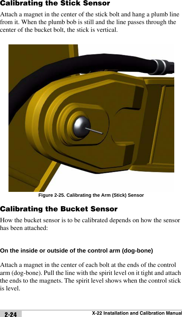
Topcon America 5434 Wireless Excavator System User Manual X 22 Installation and Calibration Manual
Topcon America Corporation Wireless Excavator System X 22 Installation and Calibration Manual
Contents
- 1. Users Manual
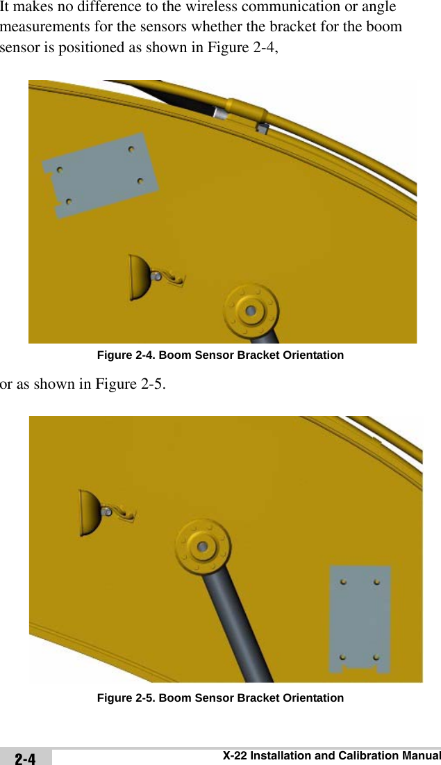
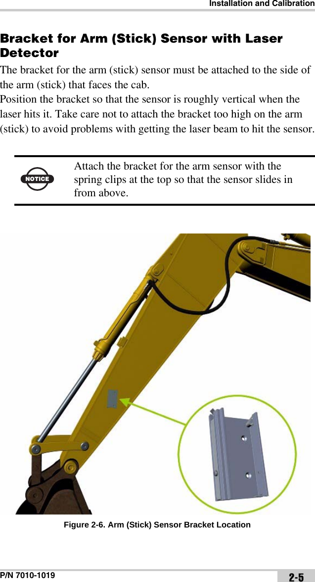
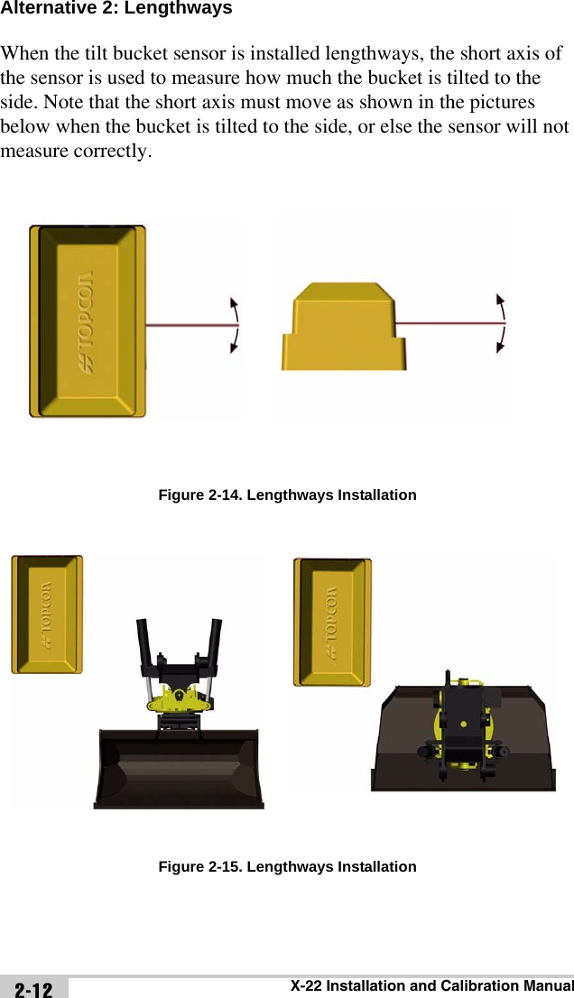
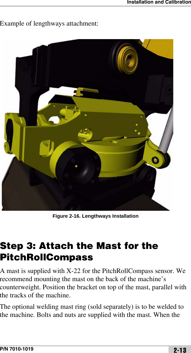
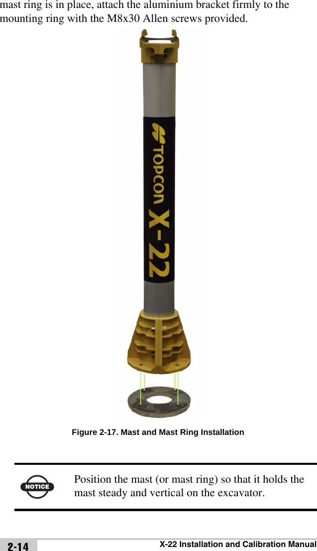
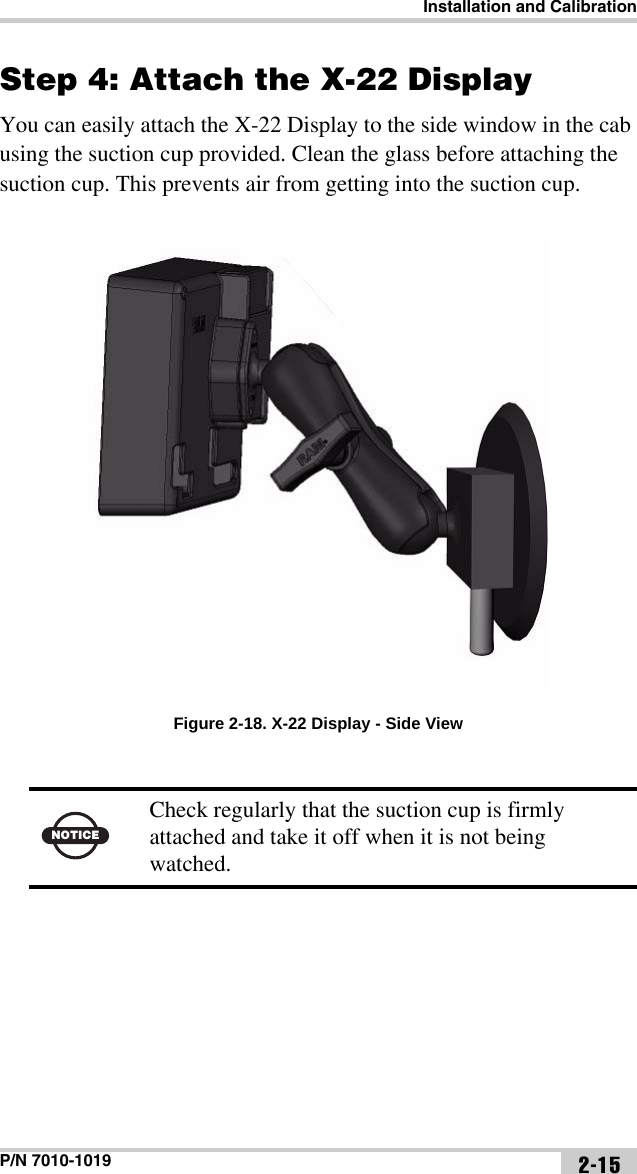
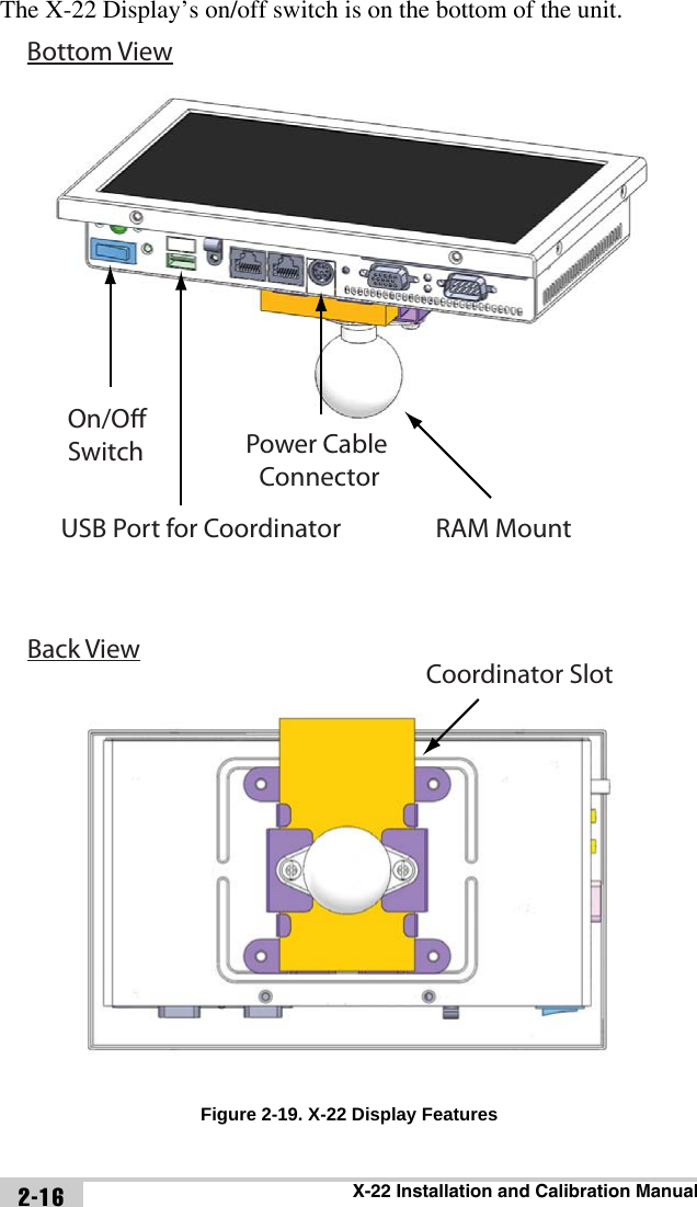
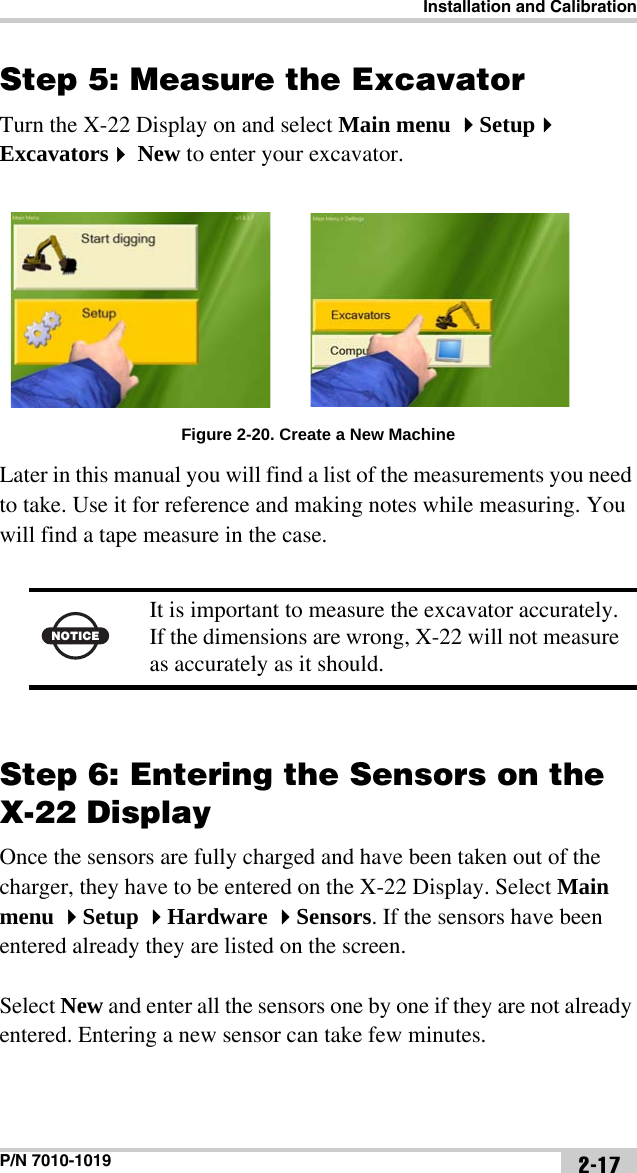
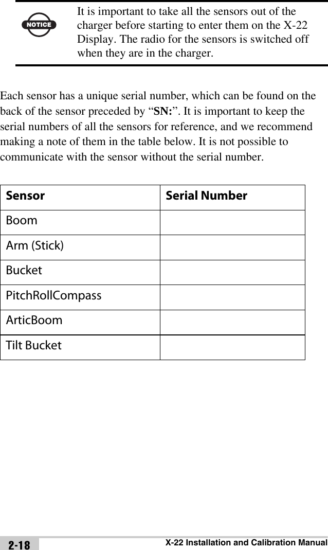
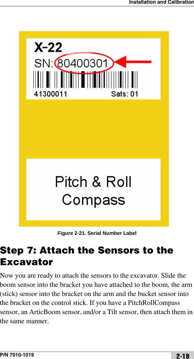
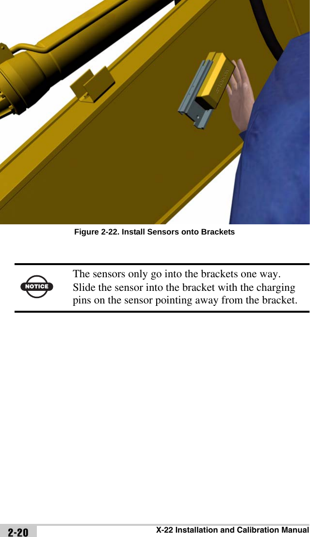
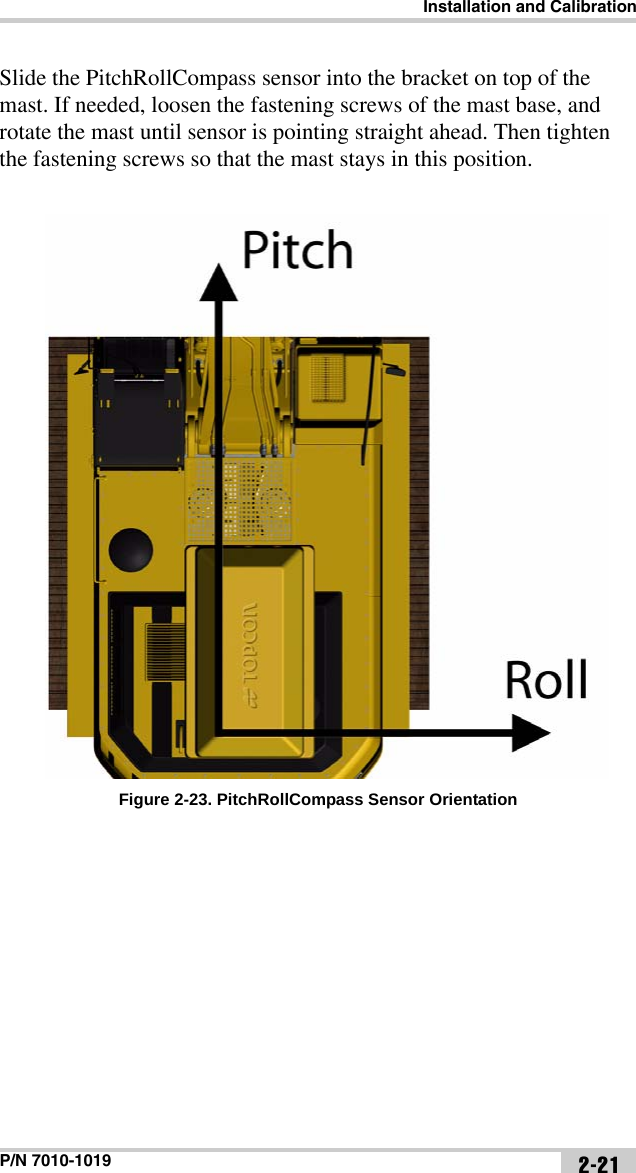
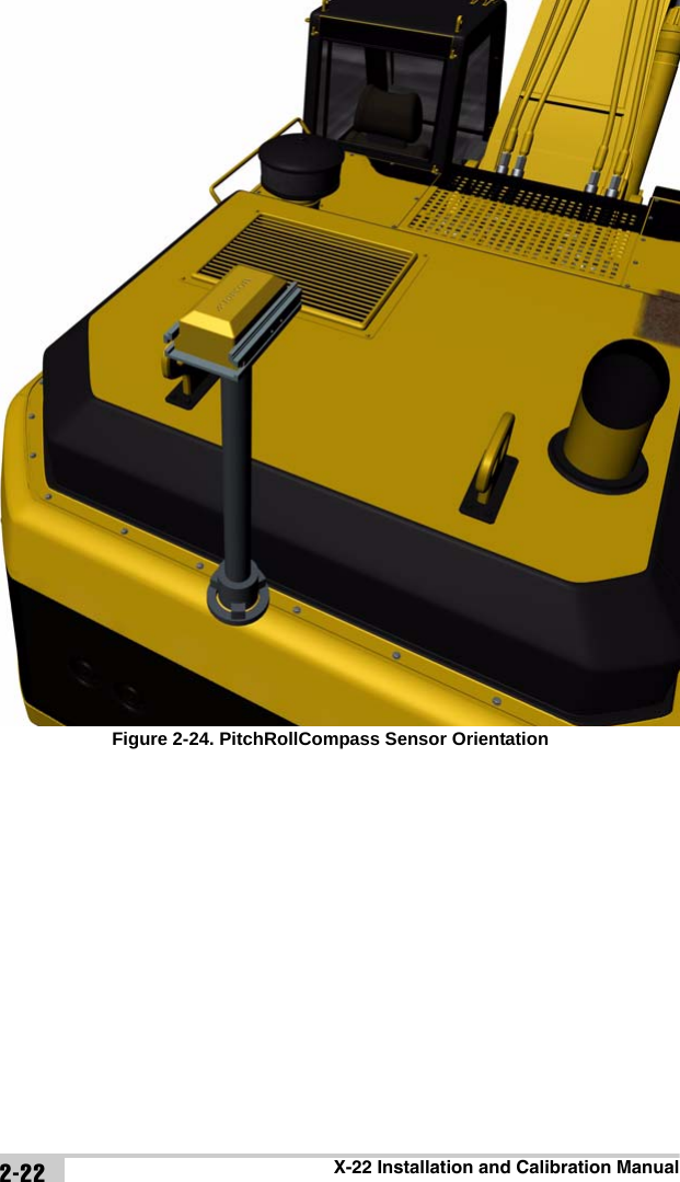
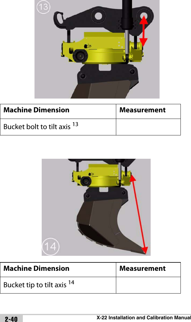
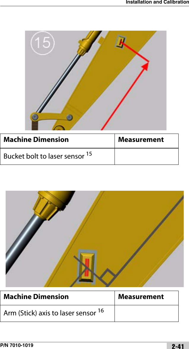
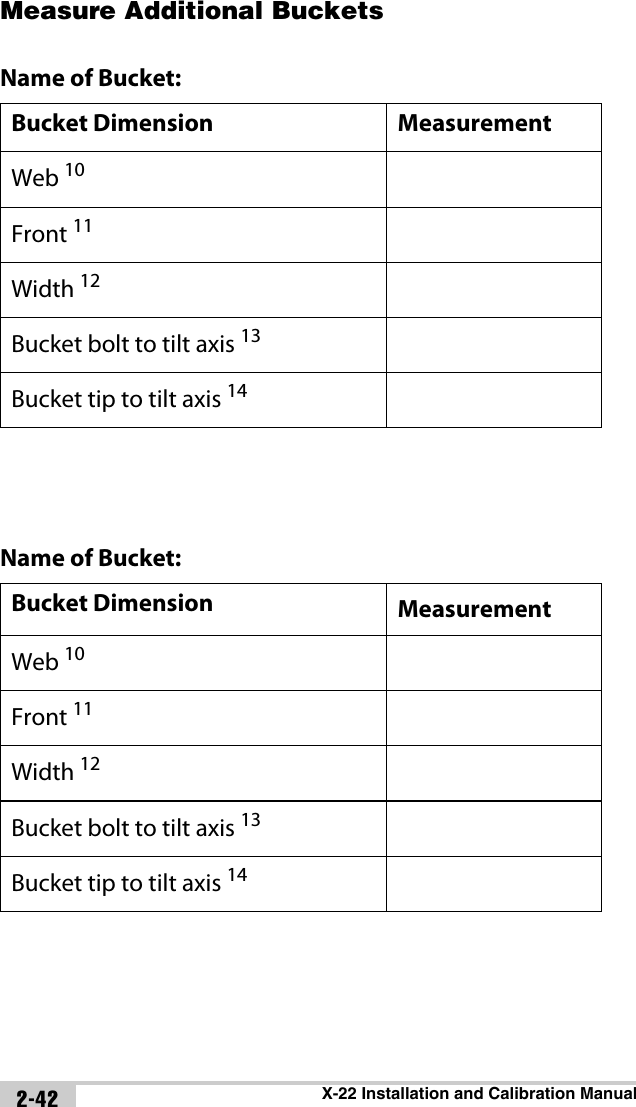
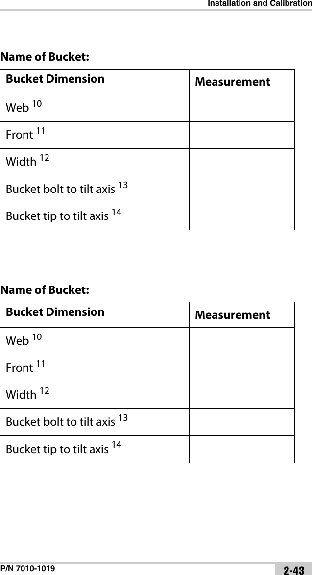
- 2. Installation Manual
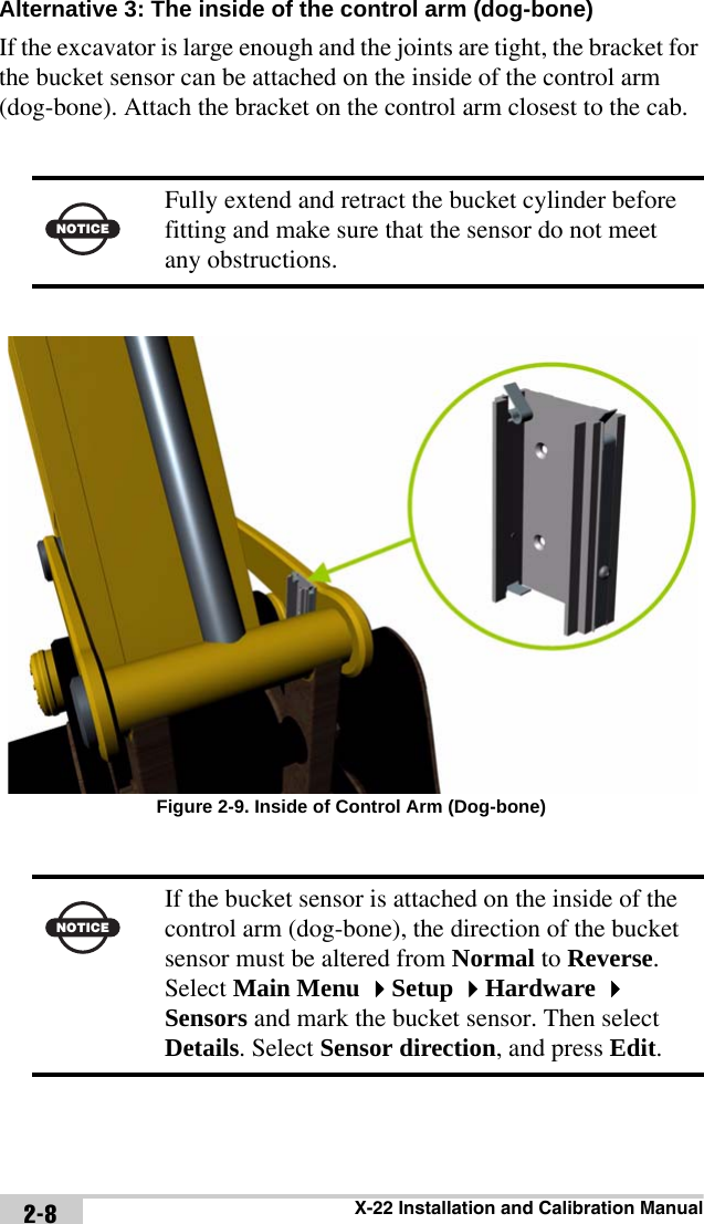
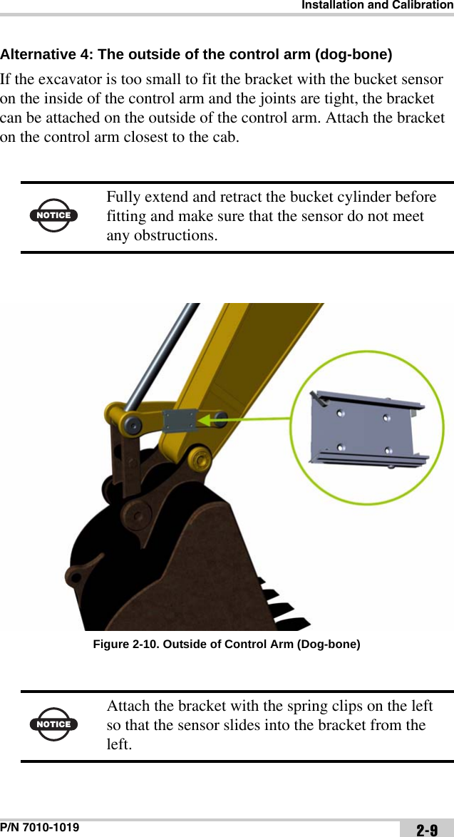
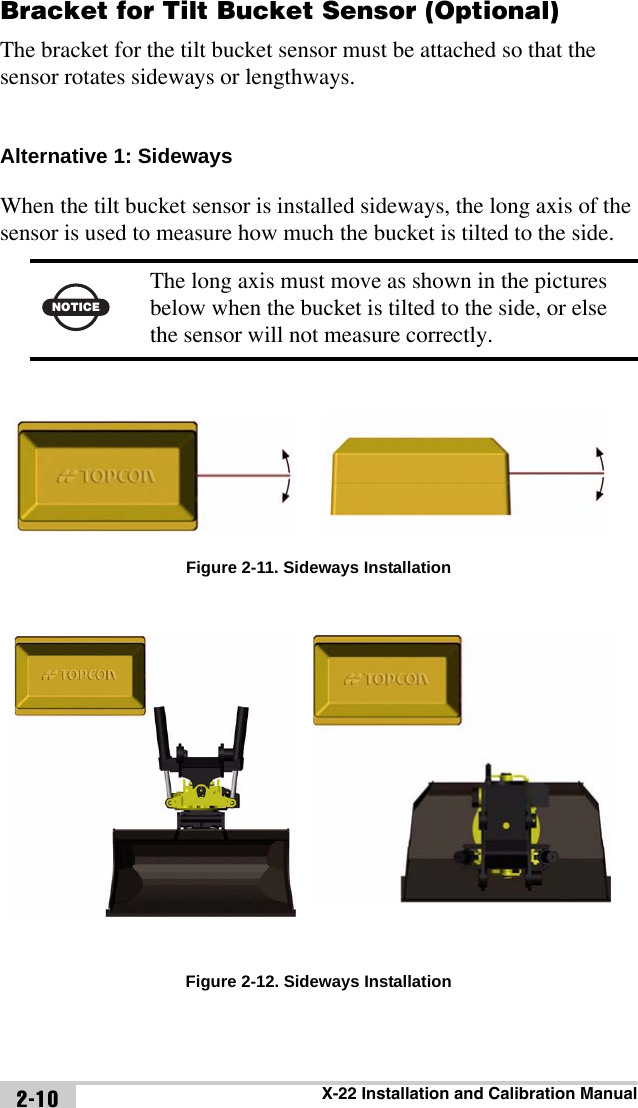
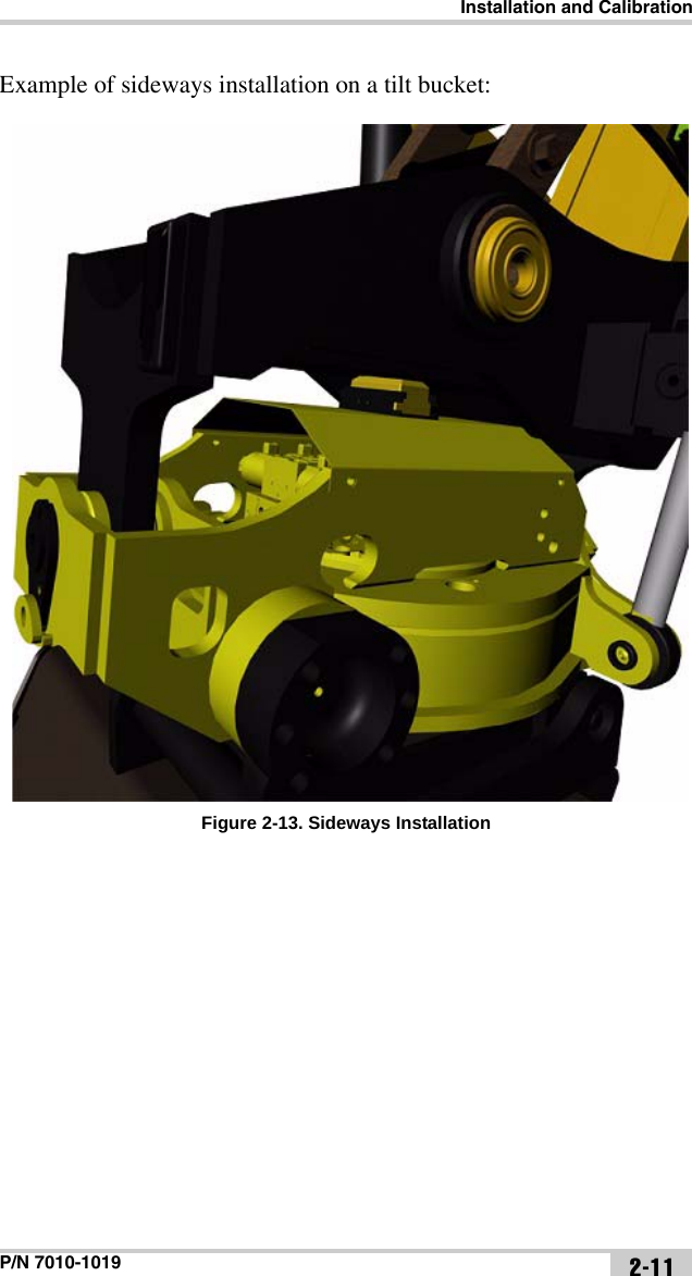
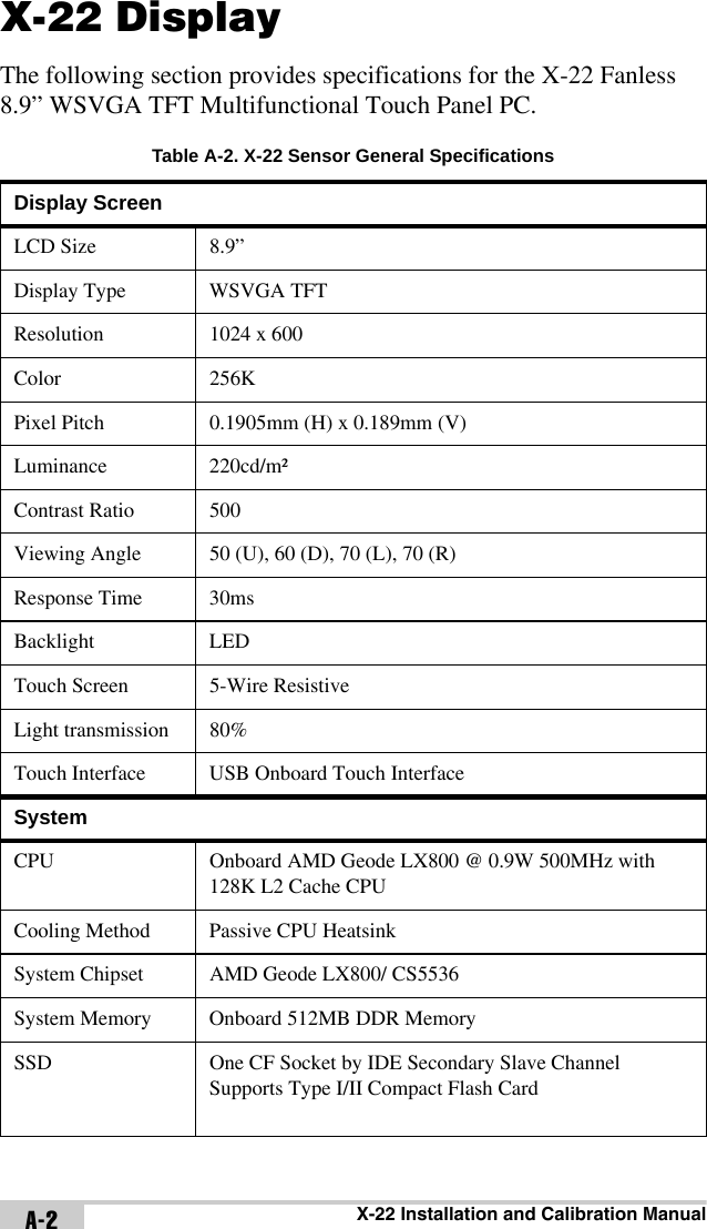
Installation Manual


 tímto prohlašuje, že tento (HiPer II) je ve shod se základními požadavky a dalšími píslušnými ustanoveními smrnice 1999/5/ES.Dansk [Danish] Undertegnede (Topcon) erklærer herved, at følgende udstyr (HiPer II) overholder de væsentlige krav og øvrige relevante krav i direktiv 1999/5/EF.Deutsch [German] Hiermit erklärt (Topcon) dass sich das Gerät (HiPer II) in Übereinstimmung mit den grundlegenden Anforderungen und den übrigen einschlägigen Bestimmungen der Richtlinie 1999/5/EG befindet.Eesti [Estonian] Käesolevaga kinnitab (Topcon) seadme (HiPer II) vastavust direktiivi 1999/5/EÜ põhinõuetele ja nimetatud direktiivist tulenevatele teistele asjakohastele sätetele.English Hereby, (Topcon) declares that this (HiPer II) is in compliance with the essential requirements and other relevant provisions of Directive 1999/5/EC.Español [Spanish] Por medio de la presente (Topcon) declara que el (HiPer II) cumple con los requisitos esenciales y cualesquiera otras disposiciones aplicables o exigibles de la Directiva 1999/5/CE. [Greek] Français [French] Par la présente (Topcon) déclare que l'appareil (HiPer II) est conforme aux exigences essentielles et aux autres dispositions pertinentes de la directive 1999/5/CE.csdadeeteneselfr](https://usermanual.wiki/Topcon-America/5434.Installation-Manual/User-Guide-1539681-Page-70.png)
![P/N 7010-1019 C-7Italiano [Italian] Con la presente (Topcon) dichiara che questo (HiPer II) è conforme ai requisiti essenziali ed alle altre disposizioni pertinenti stabilite dalla direttiva 1999/5/CE.Latviski [Latvian] Ar šo (Topcon) deklar, ka (HiPer II) atbilst Direktvas 1999/5/EK btiskajm prasbm un citiem ar to saisttajiem noteikumiem.Lietuvi [Lithuanian] Šiuo (Topcon) deklaruoja, kad šis (HiPer II) atitinka esminius reikalavimus ir kitas 1999/5/EB Direktyvos nuostatas.Nederlands [Dutch] Hierbij verklaart (Topcon) dat het toestel (HiPer II) in overeenstemming is met de essentiële eisen en de andere relevante bepalingen van richtlijn 1999/5/EG.Malti [Maltese] Hawnhekk, (Topcon) , jiddikjara li dan (HiPer II) jikkonforma mal-tiijiet essenzjali u ma provvedimenti orajn relevanti li hemm fid-Dirrettiva 1999/5/EC.Magyar [Hungarian] Alulírott, (Topcon) nyilatkozom, hogy a (HiPer II) megfelel a vonatkozó alapvetõ követelményeknek és az 1999/5/EC irányelv egyéb elõírásainak.Polski [Polish] Niniejszym, (Topcon) , deklaruj, e (HiPer II) spenia wymagania zasadnicze oraz stosowne postanowienia zawarte Dyrektywie 1999/5/EC.Português [Portugues](Topcon) declara que este (HiPer II) está conforme com os requisitos essenciais e outras disposições da Directiva 1999/5/CE.Slovensko [Slovenian](Topcon) izjavlja, da je ta (HiPer II) v skladu z bistvenimi zahtevami in ostalimi relevantnimi doloili direktive 1999/5/ES.Slovensy [Slovak](Topcon) týmto vyhlasuje, že (HiPer II) spa základné požiadavky a všetky príslušné ustanovenia Smernice 1999/5/ES.itlalinlmthuplptslda](https://usermanual.wiki/Topcon-America/5434.Installation-Manual/User-Guide-1539681-Page-71.png)
 vakuuttaa täten että (HiPer II) tyyppinen laite on direktiivin 1999/5/EY oleellisten vaatimusten ja sitä koskevien direktiivin muiden ehtojen mukainen.Svenska [Swedish] Härmed intygar (Topcon) att denna (HiPer II) står I överensstämmelse med de väsentliga egenskapskrav och övriga relevanta bestämmelser som framgår av direktiv 1999/5/EG.fisv](https://usermanual.wiki/Topcon-America/5434.Installation-Manual/User-Guide-1539681-Page-72.png)