Topcon America 5434 Wireless Excavator System User Manual X 22 Installation and Calibration Manual
Topcon America Corporation Wireless Excavator System X 22 Installation and Calibration Manual
Contents
- 1. Users Manual
- 2. Installation Manual
Installation Manual

8
)NSTALLATIONAND#ALIBRATION-ANUAL
$%XCAVATOR)NDICATE3YSTEM

POSITIONING SYSTEMS
X-22
Excavator Indicate System
Installation and Calibration
Manual
Part Number 7010-1019
Rev A
©Copyright Topcon Positioning Systems, Inc.
June, 2011
All contents in this manual are copyrighted by Topcon. All rights reserved.
The information contained herein may not be used, accessed, copied, stored,
displayed, sold, modified, published, distributed, or otherwise reproduced
without express written consent from Topcon.
ECO#4152
Terms and Conditions
Thank you for buying this Topcon product. This manual has been prepared to assist
you with the care and operation of the product and its use is subject to these Terms
and Conditions and those more fully set forth in the Operator’s/User’s Manual.
Usage and Safety
This product is designed for use by professionals. Always use safety precautions
when operating this or any Topcon product.
Copyrights
All information contained in this Manual is the intellectual property of, and
copyrighted material of TPS. All rights are reserved. You may not use, access, copy,
store, display, create derivative works of, sell, modify, publish, distribute, or allow
any third party access to, any graphics, content, information or data in this Manual
without TPS’ express written consent and may only use such information for the care
and operation of your Product. The information and data in this Manual are a valuable
asset of TPS and are developed by the expenditure of considerable work, time and
money, and are the result of original selection, coordination and arrangement by TPS.
Trademarks
X-22, Topcon, and Topcon Positioning Systems are trademarks or registered
trademarks of TPS.
Other product and company names mentioned herein may be trademarks of their
respective owners.
Disclaimer of Warranty
EXCEPT FOR SUCH WARRANTIES AND LICENSES PROVIDED WITH THE PRODUCT,
THIS MANUAL AND THE PRODUCT ARE PROVIDED “AS-IS”. TOPCON AND ITS
DISTRIBUTORS SHALL NOT BE LIABLE FOR TECHNICAL OR EDITORIAL ERRORS OR
OMISSIONS CONTAINED HEREIN; NOR FOR INCIDENTAL OR CONSEQUENTIAL
DAMAGES RESULTING FROM THE FURNISHING, PERFORMANCE OR USE OF THIS
MATERIAL OR THE PRODUCT.
Please see the Operator’s/User’s Manual for detailed information on warranties and
the license agreement which may apply to the Product.
License Agreement
Use of any computer programs or software supplied by Topcon or downloaded from
the Topcon website in connection with the Product implies acceptance of the Terms
and Conditions here and in the Operator’s/User’s Manual.
Please see the Operator’s/User’s Manual for detailed information on warranties and
the license agreement which may apply to the Product.

P/N 7010-1019
TOC
i
Table of Contents
Chapter 1
Introduction .......................................................... 1-1
System Components ........................................................ 1-1
Chapter 2
Installation and Calibration ................................. 2-1
Getting Started ................................................................. 2-1
Step 1: Charge the Sensors ........................................ 2-1
Step 2: Attach the Brackets ....................................... 2-2
Bracket for Boom Sensor ................................... 2-2
Bracket for Arm (Stick) Sensor with
Laser Detector ................................................. 2-5
Bracket for Bucket Sensor .................................. 2-6
Bracket for Tilt Bucket Sensor (Optional) ......... 2-10
Step 3: Attach the Mast for the PitchRollCompass ... 2-13
Step 4: Attach the X-22 Display ............................... 2-15
Step 5: Measure the Excavator .................................. 2-17
Step 6: Entering the Sensors on the X-22 Display .... 2-17
Step 7: Attach the Sensors to the Excavator ............. 2-19
Step 8: Calibrate the Sensors ..................................... 2-23
Calibrating the Boom Sensor .............................. 2-23
Calibrating the ArticBoom Sensor (Optional) .... 2-23
Calibrating the PitchRollCompass ...................... 2-23
Calibrating the Stick Sensor ............................... 2-24
Calibrating the Bucket Sensor ............................ 2-24
Calibrating the Tilt Bucket Sensor (Optional) .... 2-25
Step 9: Measure and Calibrate the Buckets ............... 2-25
Finding Your Way Around the Software ......................... 2-26
Tracking .................................................................... 2-26
Wizards ..................................................................... 2-26
How to Return to the Main Menu ............................. 2-27
Before You Start to Dig ................................................... 2-28

Table of Contents
X22 Installation and Calibration Manual
ii
Check that X-22 is Measuring Correctly ................... 2-28
Backup ....................................................................... 2-28
Applications ............................................................... 2-28
Arm (Stick) Sensor with Laser Detector ................... 2-29
Handling Damaged Sensors ....................................... 2-29
Important Information On Use ......................................... 2-30
Charger ...................................................................... 2-30
Sensors ....................................................................... 2-31
X-22 Display and Power Supply ............................... 2-32
Machine and Bucket Measurements ................................ 2-32
Measure Additional Buckets ............................... 2-42
Chapter 3
Troubleshooting .................................................. 3-1
Appendix A
Specifications ...................................................... A-1
X-22 Sensor ...................................................................... A-1
WEEE Directive ............................................................... A-2
Appendix B
Safety Warnings ................................................... B-1
General Warnings ............................................................. B-1
Sensor Warnings .............................................................. B-2
Usage Warnings ............................................................... B-3
Appendix C
Warranty Terms ................................................... C-1
P/N 7010-1019
Chapter 1
1-1
Introduction
Congratulations on your new X-22 System.
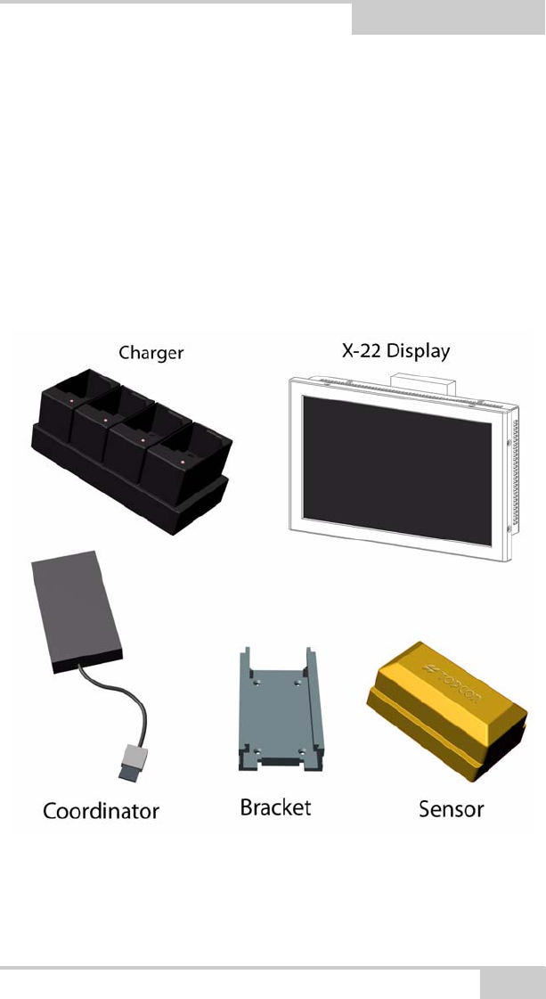
System Components
Measuring and installation equipment is also available separately (not
shown).

X-22 Installation and Calibration Manual
Notes:
1-2

P/N 7010-1019
Chapter 2
2-1
Installation and
Calibration
Getting Started
Before you can start using your X-22 System for excavation, you
need to set it up. Read on to find out how to install X-22 on your
excavator in nine simple steps.
Step 1: Charge the Sensors
The first thing you must do is charge the sensors for several hours
(i.e. overnight). The charger’s LEDs may briefly turn on and off as
the sensors go through their charging cycle. This is normal. Leave the
sensors on the charger to ensure a full charge. If the batteries are
completely flat, it takes around 12 hours to charge them fully. Make
sure the contacts on the charger and the sensors are free of debris
before charging.
Figure 2-1. Battery Charger
X-22 Installation and Calibration Manual
2-2
Step 2: Attach the Brackets
Attach the aluminum brackets using the self-tapping screws provided.
The drill and bit for the screws are also included. The drill is 4.6 mm
and the screws Taptite M5x10 have a recessed head.
A weld plates can be purchased separately, if drilling is not possible.
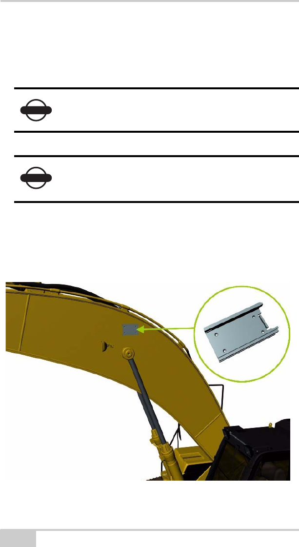
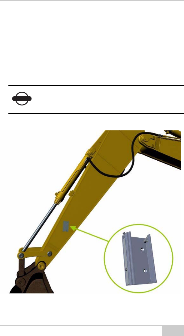
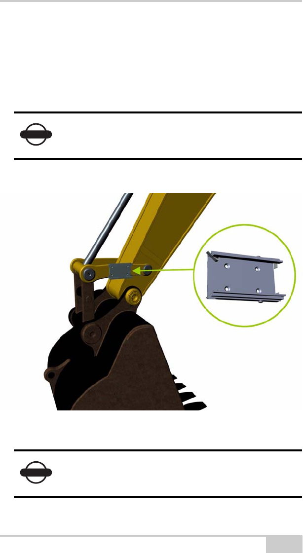
Bracket for Boom Sensor
The bracket for the boom sensor must be attached to the side of the
boom that faces the cab.
Figure 2-2. Boom Sensor Bracket Location
NOTICE
Rub a little grease or oil onto the screws before
screwing them in.
NOTICE
When determining the location of the sensor
brackets, make sure you allow room to install and
uninstall the sensors onto the brackets.
Installation and Calibration
P/N 7010-1019 2-3
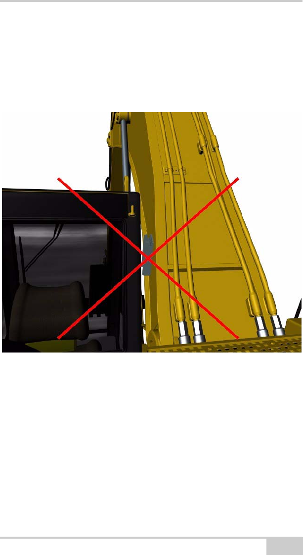
The bracket for the boom sensor must be attached to a face of the
boom that does not slant in relation to the boom bolt. The following
picture shows how the boom is widest down by the boom bolt and
gets narrower towards the center. The bracket must not therefore be
attached in this area.
Figure 2-3. Do Not Install Bracket on Slanted Area of Boom
The bracket for the ArticBoom sensor should be attached to the
articulated (extended) boom, if the machine has one, in the same way.
X-22 Installation and Calibration Manual
2-4
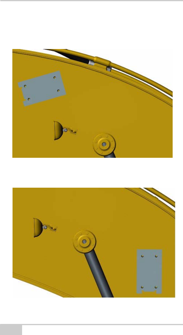
It makes no difference to the wireless communication or angle
measurements for the sensors whether the bracket for the boom
sensor is positioned as shown in Figure 2-4,
Figure 2-4. Boom Sensor Bracket Orientation
or as shown in Figure 2-5.
Figure 2-5. Boom Sensor Bracket Orientation
Installation and Calibration
P/N 7010-1019 2-5
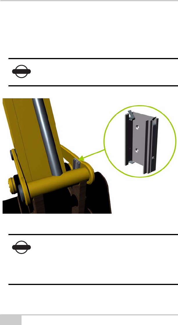
Bracket for Arm (Stick) Sensor with Laser
Detector
The bracket for the arm (stick) sensor must be attached to the side of
the arm (stick) that faces the cab.
Position the bracket so that the sensor is roughly vertical when the
laser hits it. Take care not to attach the bracket too high on the arm
(stick) to avoid problems with getting the laser beam to hit the sensor.
Figure 2-6. Arm (Stick) Sensor Bracket Location
NOTICE
Attach the bracket for the arm sensor with the
spring clips at the top so that the sensor slides in
from above.
X-22 Installation and Calibration Manual
2-6
Bracket for Bucket Sensor
The best place to attach the bracket for the bucket sensor depends on
the size of the excavator and if the joints are tight or loose.
It is easiest to make X-22 measure accurately if the bucket sensor is
attached directly on the bucket/quick coupler. This is especially the
case if the joints are loose.
Alternative 1: The inside of the quick coupler/bucket
If the excavator is large enough, the bracket for the bucket sensor can
be attached on the inside of the quick coupler/bucket. Attach the
bracket on the part of the quick coupler/bucket closest to the cab.
Figure 2-7. Quick Coupler/Bucket Bracket Location - Inside
NOTICE
Fully extend and retract the bucket cylinder before
fitting and make sure that the bracket and the sensor
do not meet any obstructions.
Installation and Calibration
P/N 7010-1019 2-7
Alternative 2: The outside of the quick coupler/bucket
The bracket for the bucket sensor can also be attached on the outside
of the quick coupler / bucket. Attach the bracket on the part of the
quick coupler/bucket closest to the cab.
Figure 2-8. Quick Coupler/Bucket Bracket Location - Outside
NOTICE
If the bucket sensor is attached on the inside of the
quick coupler/bucket, the sensor direction of the
bucket sensor must be changed from Normal to
Reverse. Select Main Menu Setup
Hardware Sensors and mark the bucket
sensor. Then select Details. Select Sensor
direction and press Edit.
X-22 Installation and Calibration Manual
2-8
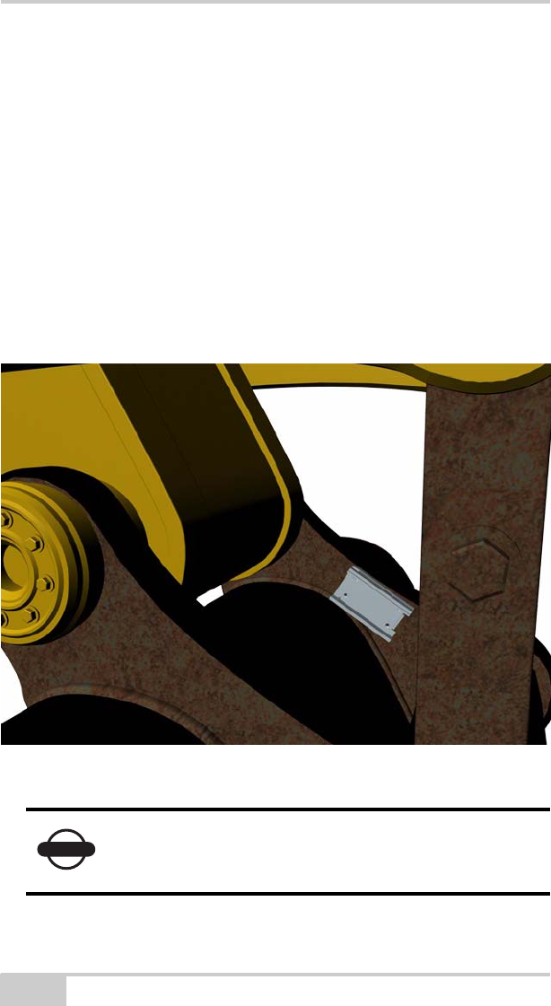
Alternative 3: The inside of the control arm (dog-bone)
If the excavator is large enough and the joints are tight, the bracket for
the bucket sensor can be attached on the inside of the control arm
(dog-bone). Attach the bracket on the control arm closest to the cab.
Figure 2-9. Inside of Control Arm (Dog-bone)
NOTICE
Fully extend and retract the bucket cylinder before
fitting and make sure that the sensor do not meet
any obstructions.
NOTICE
If the bucket sensor is attached on the inside of the
control arm (dog-bone), the direction of the bucket
sensor must be altered from Normal to Reverse.
Select Main Menu Setup Hardware
Sensors and mark the bucket sensor. Then select
Details. Select Sensor direction, and press Edit.
Installation and Calibration
P/N 7010-1019 2-9
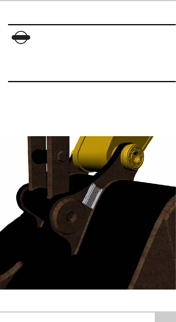
Alternative 4: The outside of the control arm (dog-bone)
If the excavator is too small to fit the bracket with the bucket sensor
on the inside of the control arm and the joints are tight, the bracket
can be attached on the outside of the control arm. Attach the bracket
on the control arm closest to the cab.
Figure 2-10. Outside of Control Arm (Dog-bone)
NOTICE
Fully extend and retract the bucket cylinder before
fitting and make sure that the sensor do not meet
any obstructions.
NOTICE
Attach the bracket with the spring clips on the left
so that the sensor slides into the bracket from the
left.
X-22 Installation and Calibration Manual
2-10
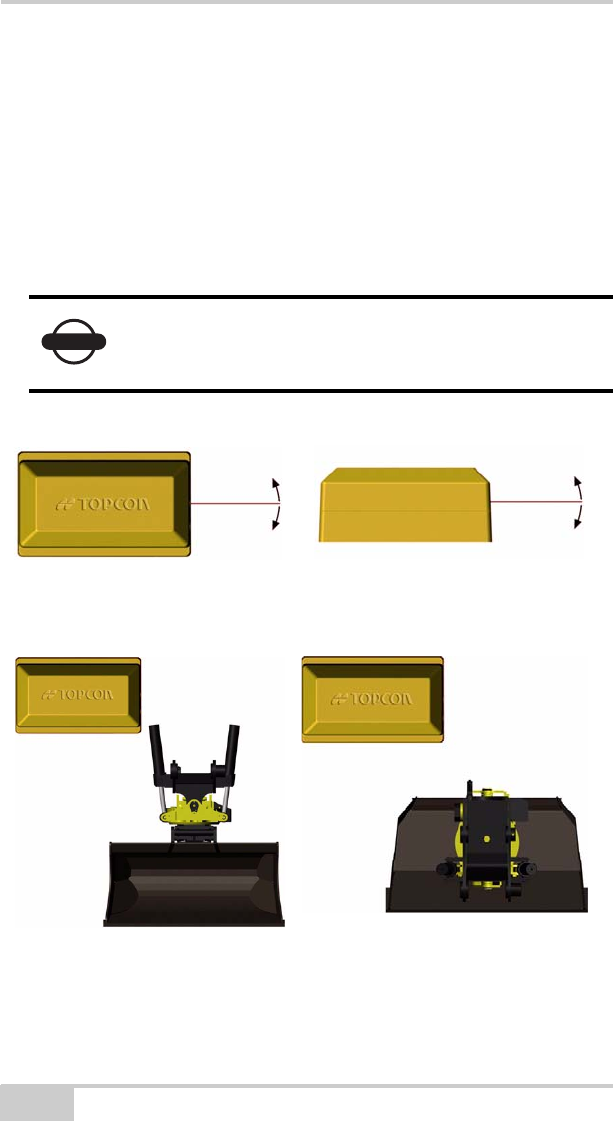
Bracket for Tilt Bucket Sensor (Optional)
The bracket for the tilt bucket sensor must be attached so that the
sensor rotates sideways or lengthways.
Alternative 1: Sideways
When the tilt bucket sensor is installed sideways, the long axis of the
sensor is used to measure how much the bucket is tilted to the side.
Figure 2-11. Sideways Installation
Figure 2-12. Sideways Installation
NOTICE
The long axis must move as shown in the pictures
below when the bucket is tilted to the side, or else
the sensor will not measure correctly.
Installation and Calibration
P/N 7010-1019 2-11
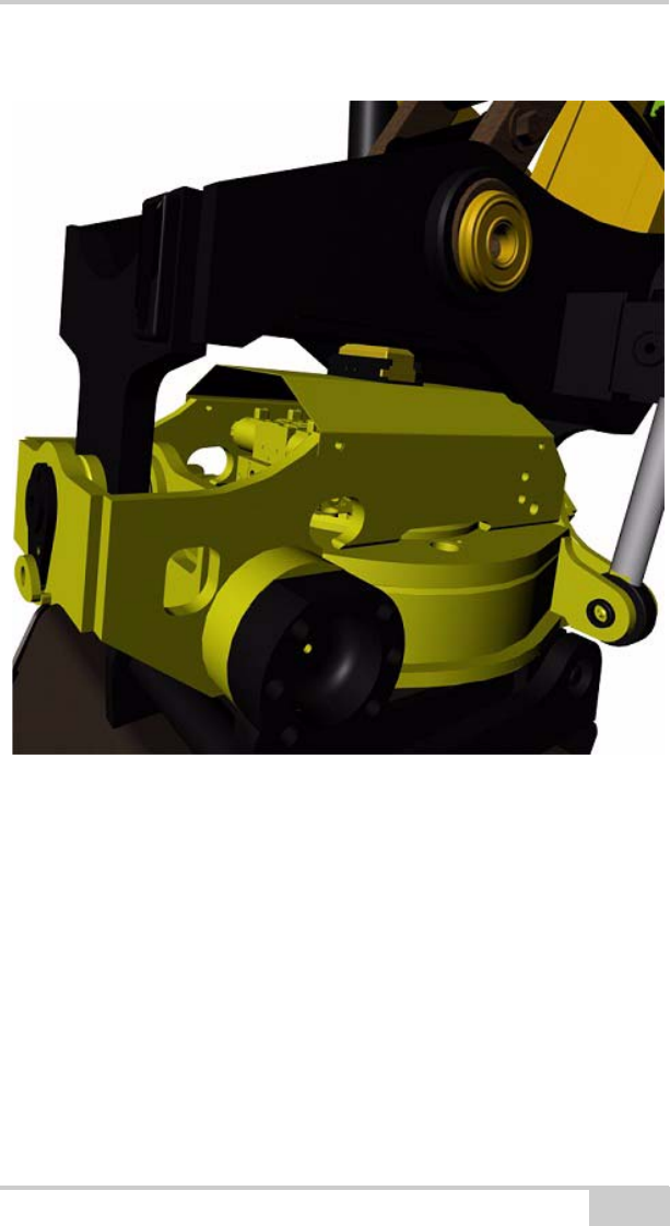
Example of sideways installation on a tilt bucket:
Figure 2-13. Sideways Installation
X-22 Installation and Calibration Manual
2-12
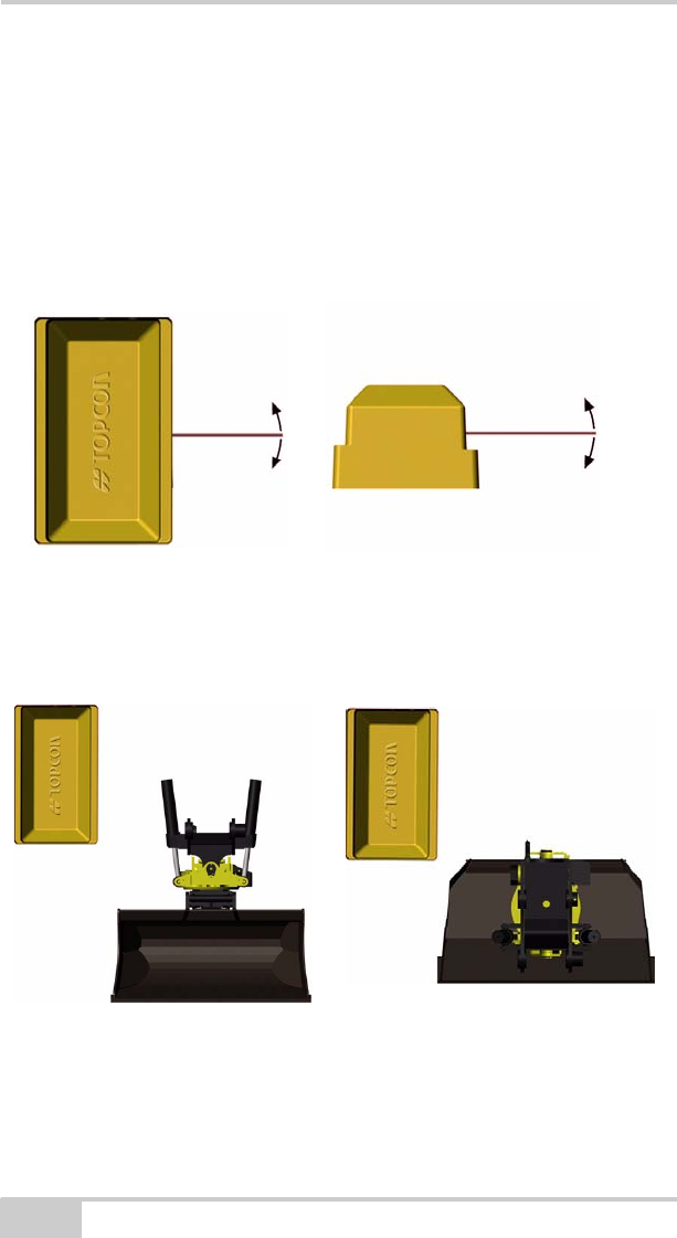
Alternative 2: Lengthways
When the tilt bucket sensor is installed lengthways, the short axis of
the sensor is used to measure how much the bucket is tilted to the
side. Note that the short axis must move as shown in the pictures
below when the bucket is tilted to the side, or else the sensor will not
measure correctly.
Figure 2-14. Lengthways Installation
Figure 2-15. Lengthways Installation
Installation and Calibration
P/N 7010-1019 2-13
Example of lengthways attachment:
Figure 2-16. Lengthways Installation
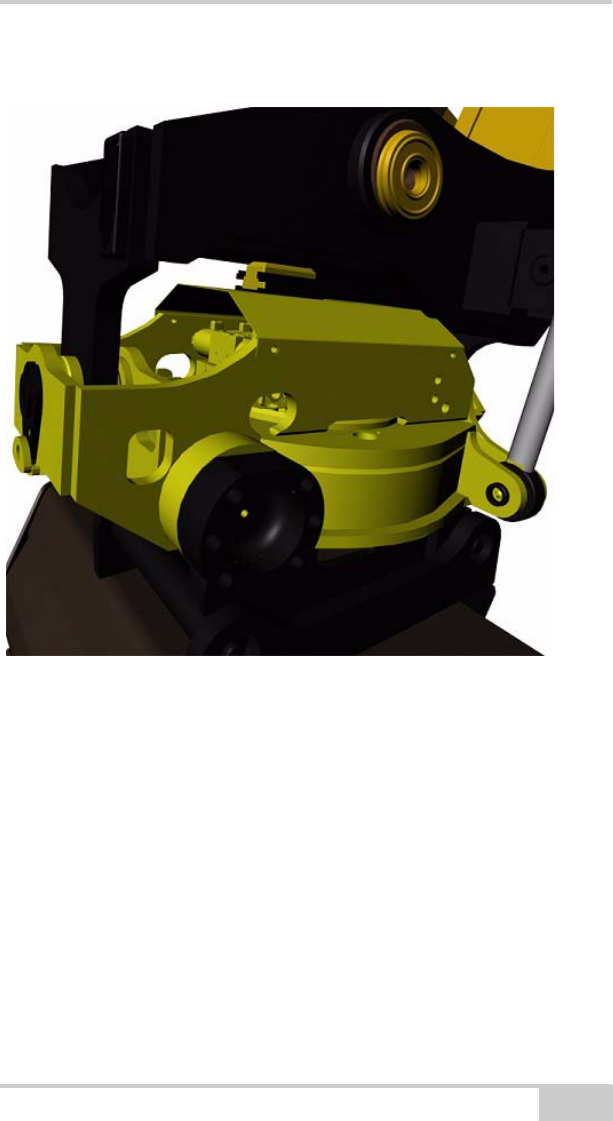
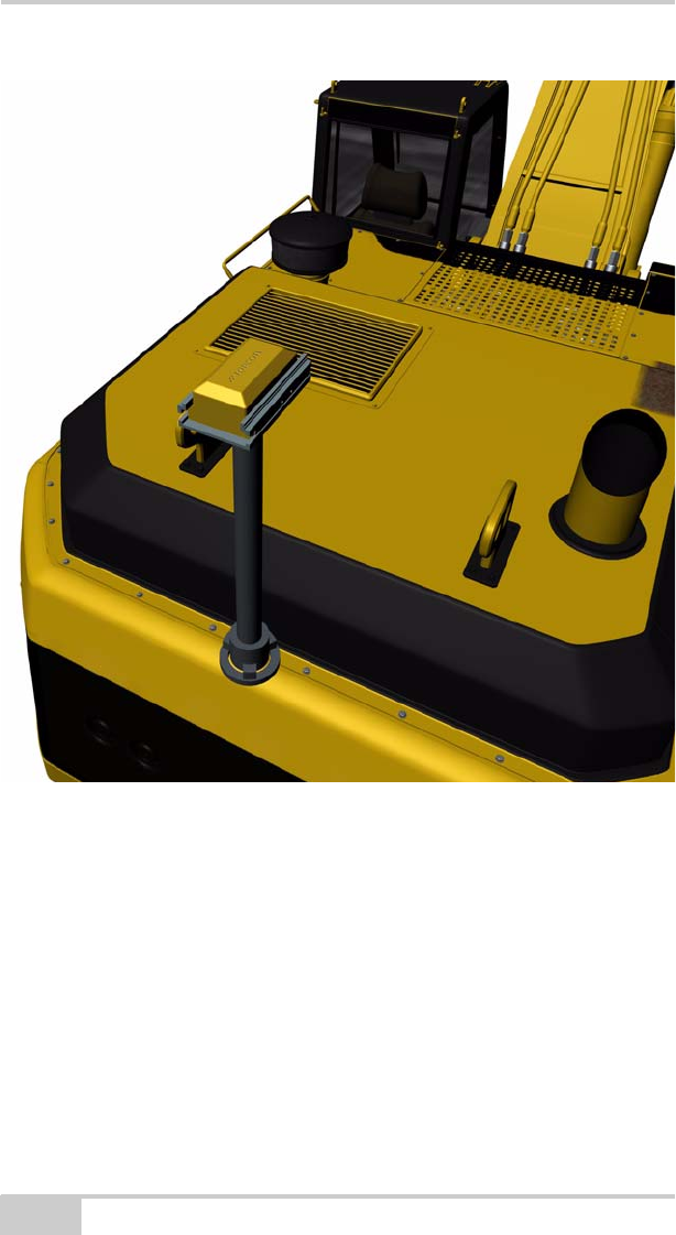
Step 3: Attach the Mast for the
PitchRollCompass
A mast is supplied with X-22 for the PitchRollCompass sensor. We
recommend mounting the mast on the back of the machine’s
counterweight. Position the bracket on top of the mast, parallel with
the tracks of the machine.
The optional welding mast ring (sold separately) is to be welded to
the machine. Bolts and nuts are supplied with the mast. When the
X-22 Installation and Calibration Manual
2-14
mast ring is in place, attach the aluminium bracket firmly to the
mounting ring with the M8x30 Allen screws provided.
Figure 2-17. Mast and Mast Ring Installation
NOTICE
Position the mast (or mast ring) so that it holds the
mast steady and vertical on the excavator.
Installation and Calibration
P/N 7010-1019 2-15
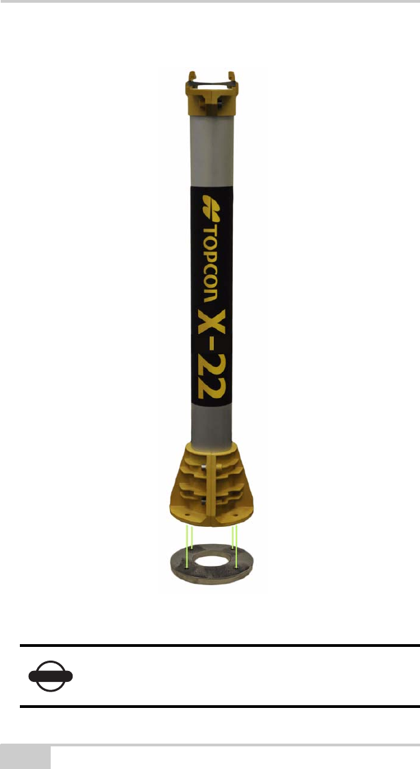
Step 4: Attach the X-22 Display
You can easily attach the X-22 Display to the side window in the cab
using the suction cup provided. Clean the glass before attaching the
suction cup. This prevents air from getting into the suction cup.
Figure 2-18. X-22 Display - Side View
NOTICE
Check regularly that the suction cup is firmly
attached and take it off when it is not being
watched.
X-22 Installation and Calibration Manual
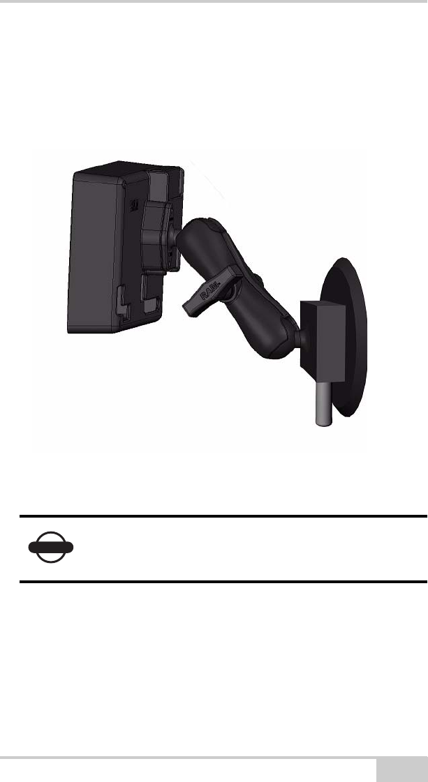
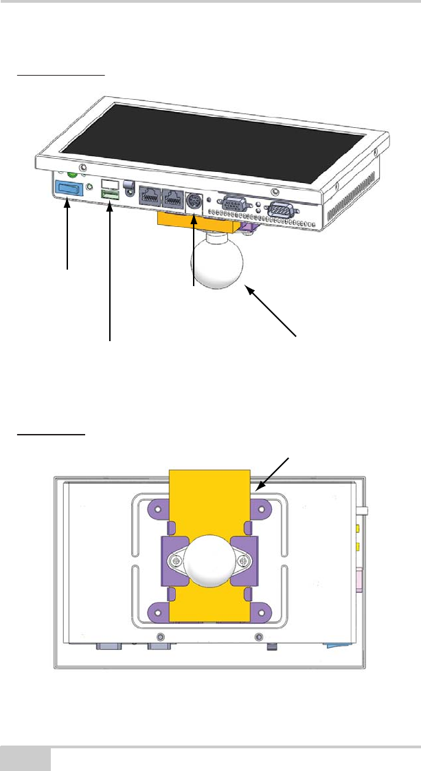
2-16
The X-22 Display’s on/off switch is on the bottom of the unit.
Figure 2-19. X-22 Display Features
On/O
Switch
USB Port for Coordinator
Power Cable
Connector
RAM Mount
Coordinator Slot
Bottom View
Back View
Installation and Calibration
P/N 7010-1019 2-17
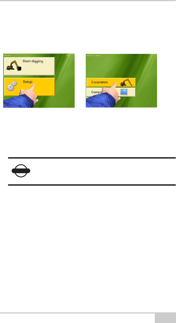
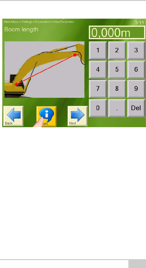
Step 5: Measure the Excavator
Turn the X-22 Display on and select Main menu Setup
Excavators New to enter your excavator.
Figure 2-20. Create a New Machine
Later in this manual you will find a list of the measurements you need
to take. Use it for reference and making notes while measuring. You
will find a tape measure in the case.
Step 6: Entering the Sensors on the
X-22 Display
Once the sensors are fully charged and have been taken out of the
charger, they have to be entered on the X-22 Display. Select Main
menu Setup Hardware Sensors. If the sensors have been
entered already they are listed on the screen.
Select New and enter all the sensors one by one if they are not already
entered. Entering a new sensor can take few minutes.
NOTICE
It is important to measure the excavator accurately.
If the dimensions are wrong, X-22 will not measure
as accurately as it should.
X-22 Installation and Calibration Manual
2-18
Each sensor has a unique serial number, which can be found on the
back of the sensor preceded by “SN:”. It is important to keep the
serial numbers of all the sensors for reference, and we recommend
making a note of them in the table below. It is not possible to
communicate with the sensor without the serial number.
NOTICE
It is important to take all the sensors out of the
charger before starting to enter them on the X-22
Display. The radio for the sensors is switched off
when they are in the charger.
Sensor Serial Number
Boom
Arm (Stick)
Bucket
PitchRollCompass
ArticBoom
Tilt Bucket

Installation and Calibration
P/N 7010-1019 2-19
Figure 2-21. Serial Number Label
Step 7: Attach the Sensors to the
Excavator
Now you are ready to attach the sensors to the excavator. Slide the
boom sensor into the bracket you have attached to the boom, the arm
(stick) sensor into the bracket on the arm and the bucket sensor into
the bracket on the control stick. If you have a PitchRollCompass
sensor, an ArticBoom sensor, and/or a Tilt sensor, then attach them in
the same manner.

X-22 Installation and Calibration Manual
2-20
Figure 2-22. Install Sensors onto Brackets
NOTICE
The sensors only go into the brackets one way.
Slide the sensor into the bracket with the charging
pins on the sensor pointing away from the bracket.
Installation and Calibration
P/N 7010-1019 2-21
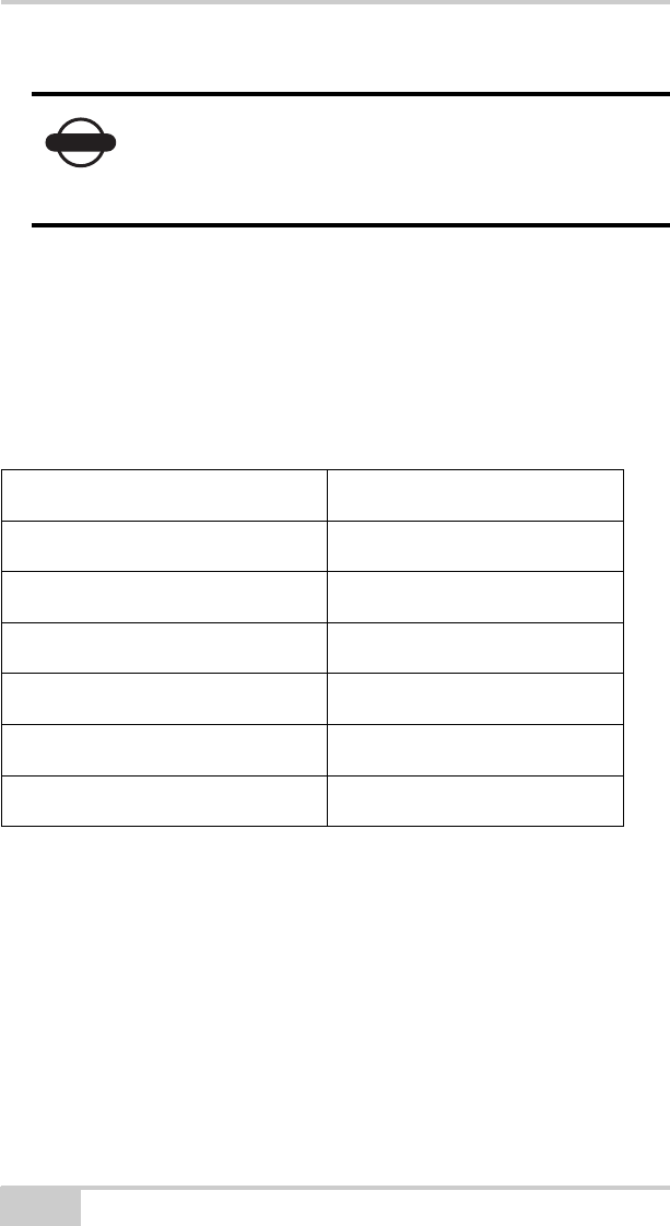
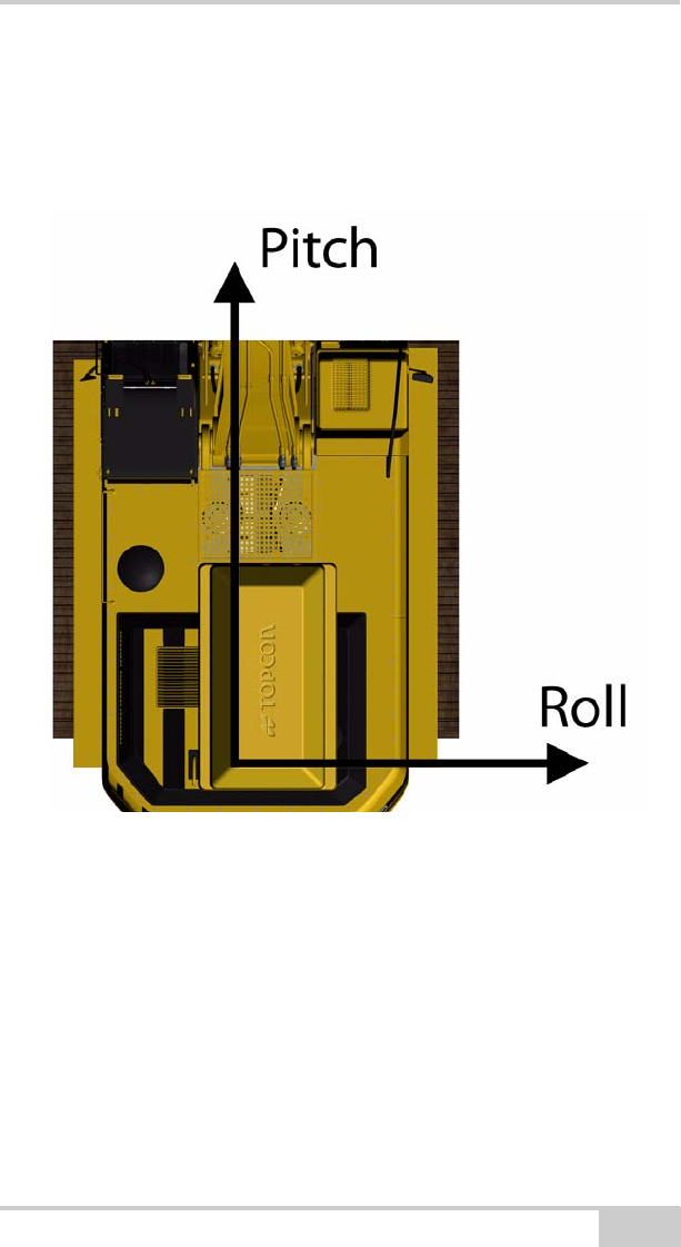
Slide the PitchRollCompass sensor into the bracket on top of the
mast. If needed, loosen the fastening screws of the mast base, and
rotate the mast until sensor is pointing straight ahead. Then tighten
the fastening screws so that the mast stays in this position.
Figure 2-23. PitchRollCompass Sensor Orientation
X-22 Installation and Calibration Manual
2-22
Figure 2-24. PitchRollCompass Sensor Orientation

Installation and Calibration
P/N 7010-1019 2-23
Step 8: Calibrate the Sensors
The sensors should now be in position on the excavator. Press Start
digging in the Main Menu and you are asked to calibrate the sensors.
Follow the on-screen instructions.
Calibrating the Boom Sensor
Attach one magnet in the center of the boom bolt and another in the
center of the stick bolt. Then thread the line through the spirit level,
pull it tight, and secure the ends to the magnets. When the spirit level
is level, the boom is level.
Calibrating the ArticBoom Sensor (Optional)
If the excavator has an articulated (extended) boom, the boom sensor
is calibrated by positioning the boom vertically, and the ArticBoom
sensor is calibrated by positioning the articulated boom horizontally.
Calibrating the PitchRollCompass
Park the excavator on a horizontal surface and position the
superstructure so that it is parallel to the tracks, following the on-
screen instructions.
Then rotate the superstructure slowly.
NOTICE
It is important to calibrate the sensors accurately. If
calibration is not done correctly, X-22 will not
measure as accurately as it should.
The most accurate sensor calibration is achieved by
using a rotating laser, theodolite or a total station
instead of the spirit level and plumb line provided.
X-22 Installation and Calibration Manual
2-24
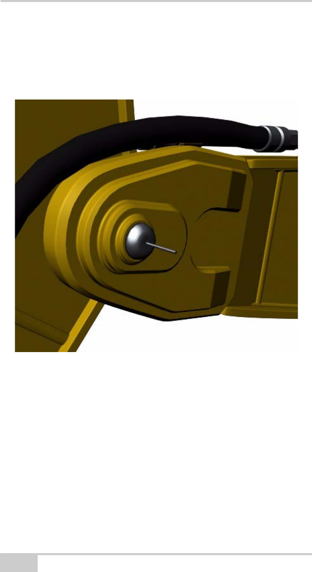
Calibrating the Stick Sensor
Attach a magnet in the center of the stick bolt and hang a plumb line
from it. When the plumb bob is still and the line passes through the
center of the bucket bolt, the stick is vertical.
Figure 2-25. Calibrating the Arm (Stick) Sensor
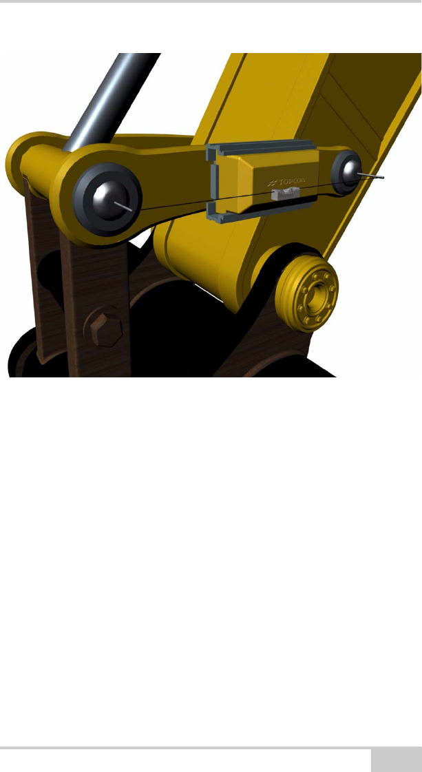
Calibrating the Bucket Sensor
How the bucket sensor is to be calibrated depends on how the sensor
has been attached:
On the inside or outside of the control arm (dog-bone)
Attach a magnet in the center of each bolt at the ends of the control
arm (dog-bone). Pull the line with the spirit level on it tight and attach
the ends to the magnets. The spirit level shows when the control stick
is level.
Installation and Calibration
P/N 7010-1019 2-25
Figure 2-26. Calibrate Control Arm (Dog-bone) Sensor
Directly on the quick coupler / bucket
If the bucket sensor has been attached directly on the quick coupler /
bucket, the sensor is calibrated by positioning the bucket vertically.
Calibrating the Tilt Bucket Sensor (Optional)
If the excavator has a tilt bucket, the tilt bucket sensor is calibrated by
positioning the tilt bucket horizontally. Follow the on-screen
instructions.
Step 9: Measure and Calibrate the
Buckets
The final step is to measure and enter the excavator’s buckets.

X-22 Installation and Calibration Manual
2-26
To enter the excavator’s buckets, select Main Menu Setup
BucketsNew.
Each bucket also has to be calibrated. Follow the instructions on the
X-22 Display.
The bucket teeth/blade can be worn down and become shorter with
time. In this case the bucket radius should be measured again and the
bucket recalibrated.
Finding Your Way Around the
Software
Buttons and lists that are displayed on screen can both be pressed.
Tracking
You can see where you are in the software right at the top of each
screen. If, for example, you press Setup in the Main Menu followed
by Excavators, Main menu > Setup > Excavators is displayed at the
top of the screen.
Wizards
When you press New to enter a new excavator, a new bucket or a new
sensor, a wizard starts up and guides you through everything you
have to do. You can see how far you have progressed in the wizard in
the top right-hand corner of the screen.
NOTICE
It is important to measure the buckets accurately. If
the dimensions are wrong, X-22 will not measure as
accurately as it should.

Installation and Calibration
P/N 7010-1019 2-27
Wizards also start up when you select the type of digging work.
How to Return to the Main Menu
To return to the previous menu, press the Back button
in the bottom left-hand corner, as shown in Figure 2-27. If you are
following a wizard, you can also go back a step by pressing Back
button. If you press Back several times, you ultimately return to the
Main Menu.
Figure 2-27. Press the Bottom Left Button to Return to Main Menu
NOTICE
Refer to the X-22 User’s Manual for more
information on using the X-22 software.

X-22 Installation and Calibration Manual
2-28
Before You Start to Dig
Check that X-22 is Measuring
Correctly
Once you have X-22 ready for digging work, we recommend
checking that the system is measuring as accurately as it should. This
can be done by running through the verification routine. The first time
you press Start digging in the Main Menu, you are asked to verify
the calibration. Otherwise, you can start the verification routine from
the menu in the digging window by pressing CheckVerify.
If the system is not measuring as accurately as it should, a dimension
or calibration value is probably wrong. In the menu in the digging
window, press Check Troubleshooting, X-22 helps you identify
the problem and rectify it.
Backup
Once you have checked that X-22 is measuring correctly, we
recommend making a backup copy of all the data you have entered on
the X-22 Display.
1. Plug a USB memory stick into the X-22 Display.
2. Select Main Menu Setup Hardware Computer
Backup/ImportBackup.
3. Press Start backup to save the measurements for all excavator(s)
and bucket(s), sensor serial numbers, etc. to the memory stick.
Applications
You can perform a wide range of digging work with X-22. In the user
manual, you will find an overview of the different types of work and
how X-22 can be used.

Installation and Calibration
P/N 7010-1019 2-29
Arm (Stick) Sensor with Laser
Detector
You should be aware that the laser detector of the arm (stick) sensor
has some limitations. It is designed for rotary lasers with laser diodes
of 1mW or more, and 630nm wavelength (visible red light). It cannot
be guaranteed that the laser detector will work with other rotary
lasers, nor if the sun shines directly onto it.
If you are unable to get the laser detector of the stick sensor to work
properly, you can use a machine detector instead. Do the following:
1. Attach the machine detector next to the stick sensor. Mark its
position so that you can attach it on the exact same place if you
have to take it off again.
2. Measure the center of the machine detector just like you did with
the stick sensor.
3. Select Main MenuSetupHardwareSensors.
4. Select Stick with laser, and press Details. The two
measurements specifying the center of the laser detector are at the
bottom of the list displayed on the screen. Edit and enter the
measurements of the machine detector instead.
5. Continue to dig and use the machine detector to reference instead
of the laser detector of the stick sensor. Make sure that “Laser” is
selected as “Reference” of the project you are working on, and
reference when the laser beam hits the center of the machine
detector.
Handling Damaged Sensors
There is a powerful lithium battery in every sensor. It is just inside the
cover bearing the serial number, so it is well protected by the sensor
housing and the aluminium bracket when the sensor is on the
excavator.
If in spite of this a sensor is seriously damaged, be careful. If a sensor
is so badly damaged that the lithium battery is punctured or squashed,
there might be a risk of explosion, fire or injury.
Damaged sensors are special waste and must be handled accordingly.
X-22 Installation and Calibration Manual
2-30
Important Information On Use
This section describes how the equipment should be handled. If the
guidelines are not followed, there might be a risk of explosion, fire,
injury or damage to the equipment.
Charger
The charger is for indoor use only. Avoid moisture. Batteries charge
faster at lower temperatures, but the sensors must never be charged at
temperatures below 0°C (32°F).
Operating temperature 0°C to +35°C
35°F to +95°F
Not waterproof
For indoor use only
NOTICE
Never put wet sensors in the charger.
NOTICE
Make sure the contacts on the sensors and the
charger are free of debris before charging.
Installation and Calibration
P/N 7010-1019 2-31
Sensors
The sensors are waterproof, but are not designed for digging in water.
The wireless connection does not work in water either, so remove the
bucket sensor and stick sensor if you intend to dig in water.
Operating temperature -20°C to +60°C
-4°F to +140°F
Charging temperature +5°C to +35°C
-41°F to +95°F
Storage temperature -20°C to +35°C
-4°F to +95°F
Operating time approx. 4 weeks on one charge
NOTICE
Never expose the sensors to temperatures above
100°C (212°F), or there might be a risk of
explosion.
NOTICE
Take the sensors off when using a pick hammer.

X-22 Installation and Calibration Manual
2-32
X-22 Display and Power Supply
The kit contains a power cable for the X-22 Display with a cigarette
lighter plug, which can be used for both 12V and 24V supply.
Machine and Bucket
Measurements
On the next several pages there are pictures illustrating all excavator
and bucket measurements that must be taken. Refer to these pictures
and make a note of the dimensions beside them while taking the
measurements.
You will find more pictures showing each measurement in greater
detail on the X-22 Display, if you press Details as shown in
Figure 2-28 on page 2-33. We recommend looking through the
pictures on the X-22 Display first and familiarizing yourself with the
various measurements before starting to measure.
Operating temperature 0°C to +50°C
35°F to +122
Storage temperature -20°C to +70°C
35°F to +158°F
Not waterproof
Installation and Calibration
P/N 7010-1019 2-33
Figure 2-28. Entering Measurements
X-22 Installation and Calibration Manual
2-34
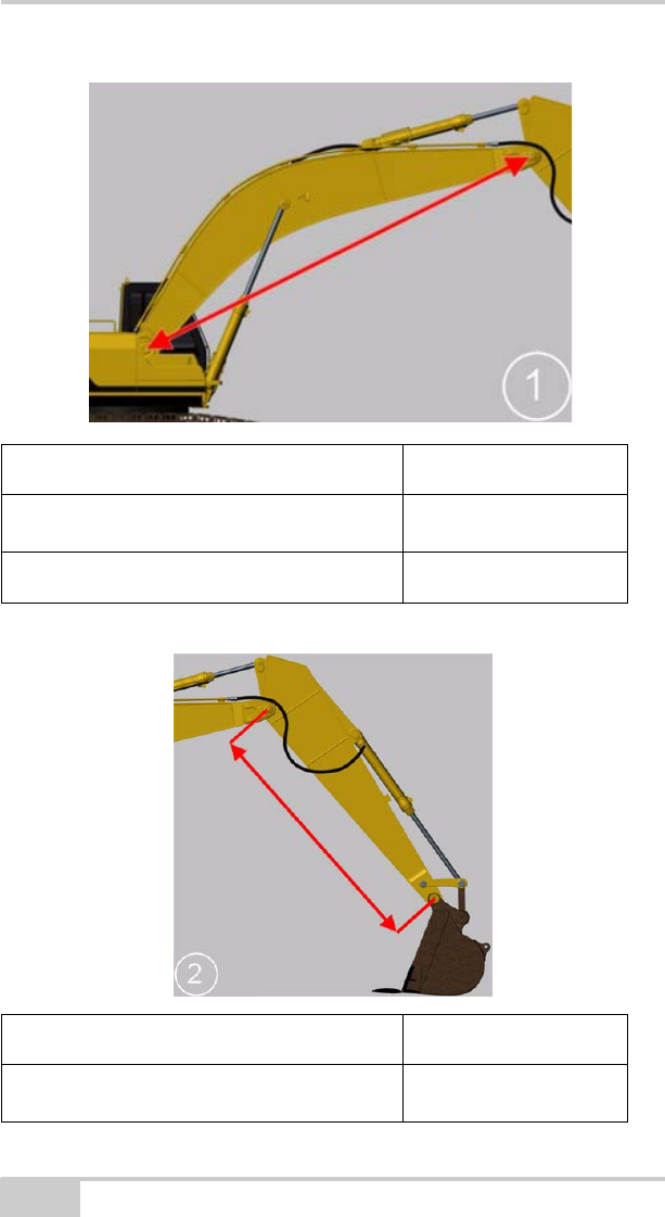
Machine Dimension Measurement
Boom 1
Articulated boom
Machine Dimension Measurement
Arm (Stick) 2
Installation and Calibration
P/N 7010-1019 2-35
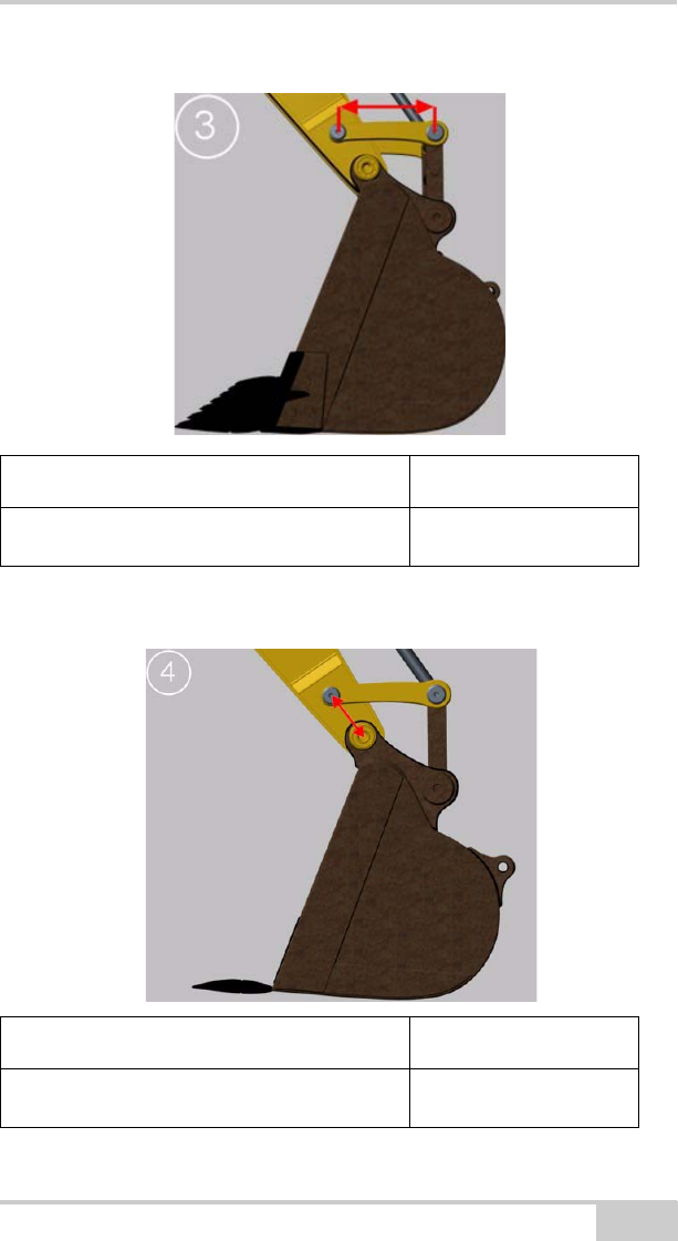
Machine Dimension Measurement
Control Arm (Dog-bone)3
Machine Dimension Measurement
Bucket bolt to control arm bolt 4

X-22 Installation and Calibration Manual
2-36
Machine Dimension Measurement
Arm (Stick) axis to
control arm (dog-bone) bolt 5
Machine Dimension Measurement
Link 6

Installation and Calibration
P/N 7010-1019 2-37
Machine Dimension Measurement
Roll length 7
Machine Dimension Measurement
Height to boom pin 8

X-22 Installation and Calibration Manual
2-38
Machine Dimension Measurement
Pitch length 9
Machine Dimension Measurement
Bucket Web 10

Installation and Calibration
P/N 7010-1019 2-39
Machine Dimension Measurement
Bucket Front 11
Machine Dimension Measurement
Bucket Width 12
X-22 Installation and Calibration Manual
2-40
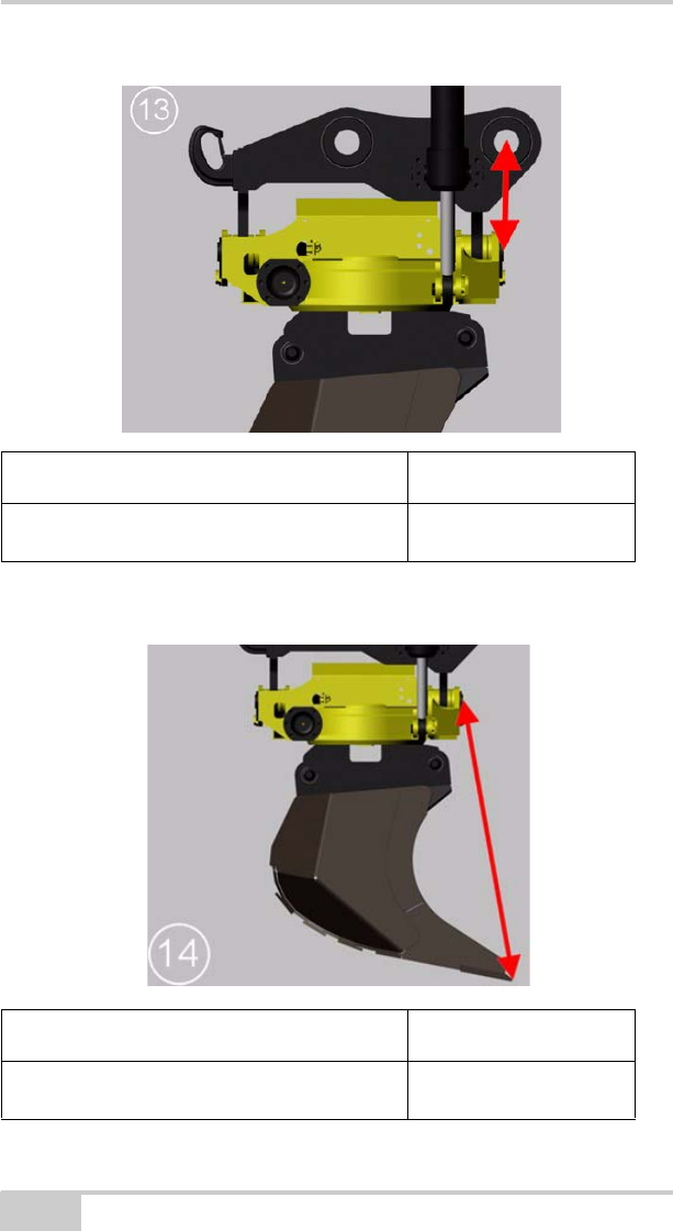
Machine Dimension Measurement
Bucket bolt to tilt axis 13
Machine Dimension Measurement
Bucket tip to tilt axis 14
Installation and Calibration
P/N 7010-1019 2-41
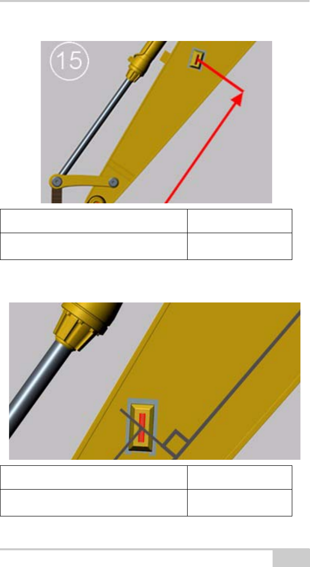
Machine Dimension Measurement
Bucket bolt to laser sensor 15
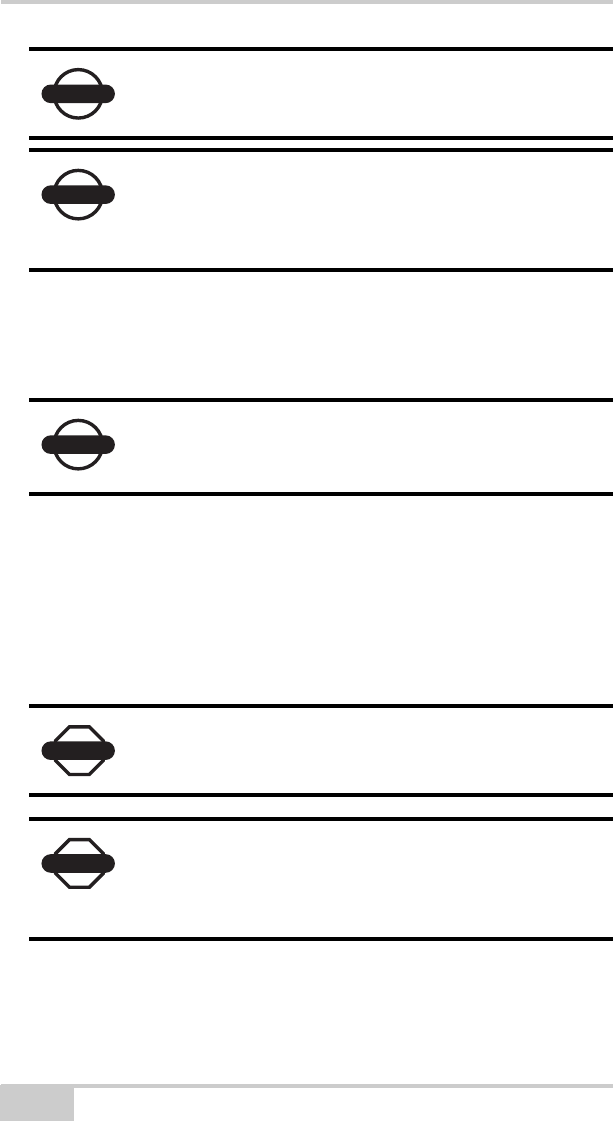
Machine Dimension Measurement
Arm (Stick) axis to laser sensor 16

X-22 Installation and Calibration Manual
2-42
Measure Additional Buckets
Name of Bucket:
Bucket Dimension Measurement
Web 10
Front 11
Width 12
Bucket bolt to tilt axis 13
Bucket tip to tilt axis 14
Name of Bucket:
Bucket Dimension Measurement
Web 10
Front 11
Width 12
Bucket bolt to tilt axis 13
Bucket tip to tilt axis 14

Installation and Calibration
P/N 7010-1019 2-43
Name of Bucket:
Bucket Dimension Measurement
Web 10
Front 11
Width 12
Bucket bolt to tilt axis 13
Bucket tip to tilt axis 14
Name of Bucket:
Bucket Dimension Measurement
Web 10
Front 11
Width 12
Bucket bolt to tilt axis 13
Bucket tip to tilt axis 14

X-22 Installation and Calibration Manual
Notes:
2-44

P/N 7010-1019
Chapter 3
3-1
Troubleshooting
In this section you will find answers to the following questions:
The X-22 Display is not responding, what should I do?....... page 3-1
The sensors are not responding, what should I do?...............page 3-1
A sensor is damaged, what should I do?..............................page 3-1
How do I recalibrate a sensor?...........................................page 3-1
The system is not measuring accurately, what should I do?..page 3-2
The compass is measuring incorrectly, what should I do?.....page 3-2
The laser sensor is not working, what should I do?...............page 3-2
The X-22 Display is not responding, what
should I do?
Most X-22 problems can be solved by turning the X-22 Display off
and on.
The sensors are not responding, what should I
do?
If you are having problems making contact with the sensors, proceed
as follows: Turn the X-22 Display off and put all the sensors in the
charger for a few minutes. The sensors will then be reset while they
are being charged. Take all the sensors out of the charger and turn the
X-22 Display back on.
A sensor is damaged, what should I do?
You can obtain a new sensor by contacting your dealer. Delete the
damaged sensor from the X-22 Display before entering the new one.

X-22 Installation and Calibration Manual
3-2
How do I recalibrate a sensor?
If you have already calibrated the sensors and want to recalibrate one,
proceed as follows: Select Main menu Setup Hardware
Sensors and highlight the sensor you want to calibrate. Select
Details. Then select Calibrated and press Change.
The system is not measuring accurately, what
should I do?
If the system is not measuring accurately, a dimension or calibration
value is probably wrong. Select Verify from the menu in the
digging window, and press Troubleshooting. X-22 will then help you
identify the problem and rectify it. Follow the on-screen instructions.
The compass is measuring incorrectly, what
should I do?
The compass in the PitchRollCompass sensor is magnetic and has to
be calibrated in order to measure correctly.
Therefore try recalibrating the compass to see if this helps. Select
Main Menu Setup Hardware Sensors
PitchRollCompass Details. Then select Calibrated, and press
Change.
If you want to check how well the compass is calibrated, you can
select Main MenuSetupHardwareSensors
PitchRollCompassVerify. When the machine is stationary and the
superstructure is rotated, the compass measurements should ideally
form a perfect circle with the center at the origin.
In certain special circumstances the magnetic compass can be
disrupted so much that it should not be used. In this situation the
heading on the screen can change even if the machine is at a complete
standstill.
If this happens, the compass should be turned off. Select Main menu
Setup Hardware Sensors and highlight the
PitchRollCompass sensor. Select “Details”. Then select “Compass
on” and press “Change”. All the software functions that use the

Troubleshooting
P/N 7010-1019 3-3
heading measurements from the compass will now disappear and you
will have to keep track of the heading yourself.
In situations where there are large fluctuations in the magnetic field
around the machine all the time, the compass calibration will not be
able to compensate for the disturbances. An example of such a
situation is if the machine is close to a railway line that is in use:
Trains are surrounded by a strong magnetic field, which will badly
disrupt the compass measurements whenever a train goes past. In this
case the heading displayed on the screen could change even if the
machine is at a complete standstill.
Working in the vicinity of high-voltage cables can also cause
problems for the magnetic compass.
The laser sensor is not working, what should I
do?
The laser sensor may have problems detecting the laser beam in
strong sunlight, particularly if the sun is shining straight into the
photoelectric cell. If this happens, the amount of sunlight hitting the
cell will have to be reduced by turning the sensor away from the sun,
for example.
If the laser sensor is exposed to strobe lighting, a rotating flashing
light or the like, the sensor may be misled into thinking that it has
detected the laser.
If the laser sensor does not respond to the laser beam at all, even at
close range, the photoelectric cell has probably been damaged. In this
case you will have to contact your dealer to have the sensor replaced.

X-22 Installation and Calibration Manual
Notes:
3-4

P/N 7010-1019 A-1
Specifications
X-22 Sensor
The following section provides specifications for the X-22 Sensor.
Table A-1. X-22 Sensor General Specifications
General Details
Enclosure Xenoy CL 100 Polycarbonate
Resistant to hydraulic fluids, diesel and UV exposure
IP67
Color Topcon Yellow
Dimensions W: 112 mm x H: 48 mm x D: 68 mm
W: 4.4 in. x H: 1.89 in. x D: 2.68 in.
Weight 230g (standard sensor)
0.5 lbs.
Battery Operating time: Up to four weeks with normal use
Material: Lithium-ion polymer
Nominal capacity: 5600mAh
Charging time: Overnight
Expected battery life: Beyond 3 years
Operating
temperature
-20°C to +60°C
-4°F to +140°F
Charging
temperature
+5°C to +35°C
-41°F to +95°F
Storage temperature -20°C to +35°C
-4°F to +95°F
Radio Range: Over 50m (164 ft) line-of-sight
Frequency: 2.4 GHz license-free ISM-band
Proprietary packet radio protocol
Connectors 2 charging pins (6V DC input, no polarity)

X-22 Installation and Calibration Manual
A-2
X-22 Display
The following section provides specifications for the X-22 Fanless
8.9” WSVGA TFT Multifunctional Touch Panel PC.
Table A-2. X-22 Sensor General Specifications
Display Screen
LCD Size 8.9”
Display Type WSVGA TFT
Resolution 1024 x 600
Color 256K
Pixel Pitch 0.1905mm (H) x 0.189mm (V)
Luminance 220cd/m²
Contrast Ratio 500
Viewing Angle 50 (U), 60 (D), 70 (L), 70 (R)
Response Time 30ms
Backlight LED
Touch Screen 5-Wire Resistive
Light transmission 80%
Touch Interface USB Onboard Touch Interface
System
CPU Onboard AMD Geode LX800 @ 0.9W 500MHz with
128K L2 Cache CPU
Cooling Method Passive CPU Heatsink
System Chipset AMD Geode LX800/ CS5536
System Memory Onboard 512MB DDR Memory
SSD One CF Socket by IDE Secondary Slave Channel
Supports Type I/II Compact Flash Card

P/N 7010-1019 A-3
Rear Panel I/O
Serial Port 1 x RS-232, 1 x RS-232 or Optional RS-422/ 485
Ethernet 2 x RJ-45 (Realtek RTL8101L LAN)
WIFI Optional USB WiFi 802.11 b/g (Occupies One USB Port)
VGA 1 x DB-15
Audio Line-out, Mic-in
USB 2 x USB 2.0
Mouse & K/B 1 x PS/2 Keyboard Connector
Environment & Mechanical
Color Front Panel Black; Rear Panel Black
Mounting Wall/ Stand/ VESA 75mm x 75mm
Power Input 100 ~ 250Vdc/ 47 ~ 63Hz
Power Output +12Vdc/ 5A (60W)
Operating
Temperature
-10°C ~ 60°C
14°F to +140°F
Storage
Temperature
-20°C ~ 70°C
-4°F to +158°F
Relative Humidity 10% to 95% @ 40°C, Non-condensing
Dimension W: 225mm x H: 139mm x D: 38.9mm
W: 8.86 in. x H: 5.47 in. x D: 1.53 in.
Weight 1.26Kgs (2.78 lbs.)
Table A-2. X-22 Sensor General Specifications (Continued)

X-22 Installation and Calibration Manual
Notes:
A-4

P/N 7010-1019
Appendix B
B-1
Safety Warnings
General Warnings
1. Read and become familiar with the machine manufacturer’s
operating instructions, including safety information, before
installing or using your Topcon equipment.
2. Use extreme caution on the jobsite. Working around heavy
construction equipment can be dangerous.
3. DO NOT attach system brackets while the machine is running.
4. DO NOT allow any X-22 system component to limit the visibility
of the operator.
5. Use Ty-wraps, to keep hoses and wires secured and away from
possible wear or pinch points.
6. Use eye protection whenever welding, cutting, or grinding is
being done on the machine.
7. Protect yourself at all times, and wear protective clothing, when
working on or near hydraulic lines. Avoid direct exposure to your
eyes when using laser control.
8. Use appropriate welding precautions and practices when welding.
After welding, all paint all affected areas with a rust inhibitor.
CAUTION
DO NOT stare into the laser beam or view the beam
directly with optical equipment.
WARNING
DO NOT weld near hydraulic lines or on any
equipment when in operation.
X-22 Installation and Calibration Manual
B-2
9. To prevent vandalism or theft, do not leave removable Topcon
components on the machine at night. Remove the components
each evening and store appropriately in the carrying case.
10. Keep the carrying case dry at all times.
If moisture does enter the carrying case, leave it open and allow it
to thoroughly dry before storing any components.
Sensor Warnings
NOTICE
Disconnect all Topcon system electrical cables
prior to welding on the machine.
NOTICE
All mounting bracket welds must be secure and
strong to prevent sensor equipment from vibrating
excessively or from becoming detached at the weld
during operation.
NOTICE
DO NOT allow moisture to get inside the case.
Moisture trapped in the case can adversely affect
components.
DANGER
Never attempt to open the X-22 sensors! Lithium-
Ion batteries can be dangerous if mishandled!
DANGER
Do not incinerate or heat battery pack above 212
degrees fahrenheit (100 degrees celsius). Excessive
heat can cause serious damage and possible
explosion.
P/N 7010-1019 B-3
Usage Warnings
WARNING
Tampering with the batteries by end users or non-
factory authorized technicians will void the
battery’s warranty.
• Do not attempt to open the sensors.
• Do not disassemble the sensor.
• Do not charge in conditions different than
specified.
• Do not use other than the specified battery
charger.
• Do not short circuit.
• Do not crush or modify.
CAUTION
If this product has been dropped, altered,
transported or shipped without proper packaging, or
otherwise treated without care, erroneous
measurements may occur.
The owner should periodically test this product to
ensure it provides accurate measurements.
Inform Topcon immediately if this product does not
function properly.
CAUTION
Only allow authorized Topcon warranty service
centers to service or repair this product.

X-22 Installation and Calibration Manual
Notes:
B-4

P/N 7010-1019
Appendix C
C-1
Regulatory Information
The following sections provide information on this product’s
compliance with government regulations for use.
FCC Compliance
This device complies with Part 15 of the FCC rules. Operation is
subject to the following two conditions:
1. This device may not cause harmful interference, and
2. This device must accept any interference received, including
interference that may cause undesired operation.
This equipment has been tested and found to comply with the limits
for a digital device, pursuant to Part 15 of the FCC rules. These limits
are designed to provide reasonable protection against harmful
interference in residential installations. This equipment generates,
uses, and can radiate radio frequency energy, and if not installed and
used in accordance with the instructions, may cause harmful
interference to radio communications. However, there is no guarantee
that interference will not occur in a particular installation.
If this equipment does cause interference to radio or television
equipment reception, which can be determined by turning the
equipment off and on, you are encouraged to try to correct the
interference by one or more of the following measures:
• Reorient or relocate the receiving antenna.
• Move the equipment away from the receiver.
• Plug the equipment into an outlet on a circuit different from that
to which the receiver is powered.
• Consult the dealer or an experienced radio/television technician
for additional suggestions.

X-22 Installation and Calibration Manual
C-2
FCC Compliance
This equipment complies with FCC radiation exposure limits set forth
for uncontrolled equipment and meets the FCC radio frequency (RF)
Exposure Guidelines in Supplement C to OET65. This equipment has
very low levels of RF energy that it deemed to comply without
maximum permissive exposure evaluation (MPE). But it is desirable
that it should be installed and operated with at least 20cm and more
between the radiator and person’s body (excluding extremities:
hands, wrists, feet and ankles). This device complies with Part 15 of
the FCC rules. Operation is subject to the following two conditions:
1. This device may not cause harmful interference, and
2. This device must accept any interference received, including
interference that may cause undesired operation.
This equipment has been tested and found to comply with the limits
for a digital device, pursuant to Part 15 of the FCC rules. These limits
are designed to provide reasonable protection against harmful
interference in residential installations. This equipment generates,
uses, and can radiate radio frequency energy, and if not installed and
used in accordance with the instructions, may cause harmful
interference to radio communications. However, there is no guarantee
that interference will not occur in a particular installation.
If this equipment does cause interference to radio or television
equipment reception, which can be determined by turning the
equipment off and on, the user is encouraged to try to correct the
interference by one or more of the following measures:
• Reorient or relocate the receiving antenna.
• Move the equipment away from the receiver.
CAUTION
Any changes or modifications to the equipment not
expressly approved by the party responsible for
compliance could void your authority to operate
such equipment.

P/N 7010-1019 C-3
• Plug the equipment into an outlet on a circuit different from that
to which the receiver is powered.
• Consult the dealer or an experienced radio/television technician
for additional suggestions.
Federal Communication Commission
Declaration of Conformity (DoC) Statement
Model No: HiPer II
CAUTION
Any changes or modifications to the equipment not
expressly approved by the party responsible for
compliance could void your authority to operate
such equipment.
Trade Name Topcon
Responsible Party Topcon Positioning
Systems, Inc.
Address
7400 National Drive,
Livermore, CA 94550
Telephone No +925-245-8300

X-22 Installation and Calibration Manual
C-4
Canadian Emission Labeling
Requirements
This equipment complies with IC radiation exposure limits set forth
for uncontrolled equipment and meets RSS-102 of the IC radio
frequency (RF) Exposure rules. This equipment has very low levels
of RF energy that it deemed to comply without maximum permissive
exposure evaluation (MPE). But it is desirable that it should be
installed and operated with at least 20cm and more between the
radiator and person’s body (excluding extremities: hands, wrists, feet
and ankles).
1. Operation is subject to the following two conditions: (1) this
device may not cause interference, and (2) this device must
accept any interference, including interference that may cause
undesired operation of the device.
2. To reduce potential radio interference to other users, the antenna
type and its gain should be so chosen that the equivalent
isotropically radiated power (e.i.r.p.) is not more than that
permitted for successful communication.
3. This Class B digital apparatus meets all requirements of the
Canadian Interference-Causing Equipment Regulations.
Cet appareil numérique de la classe B respecte conform a la norme
NMB-003 du Canada.
IC RF Radiation Exposure Statement
This installer of this device must ensure that the antenna is located or
pointed such that it dose not emit RF field in excess of Health Canada
limits for the general population; consult Safety Code 6, obtainable
from Health Canada’s website at www.hc-sc.gc.ca/rpb.

P/N 7010-1019 C-5
Community of Europe
Compliance
The product described in this manual is in compliance with the
R&TTE and EMC directives from the European Community.
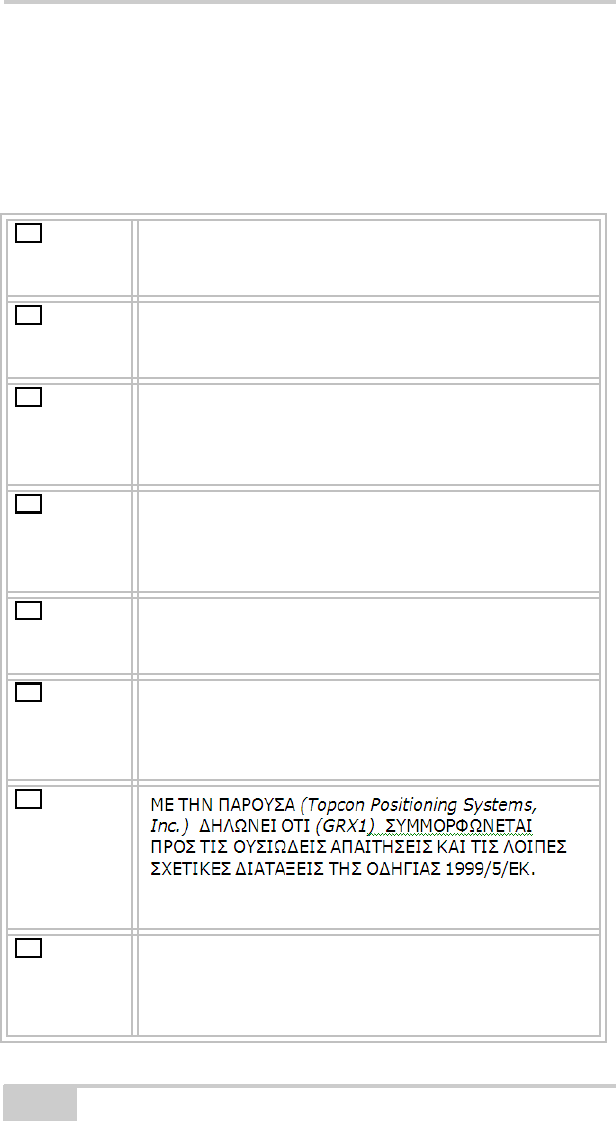
European Community Declaration of
Conformity with R&TTE Directive 1999/5/EC
The following standards were applied: (R&TTE Directive 1999/5/EEC)
• EN 301 489-1 V1.8.1 (2008-04)
• EN 301 489-17 V1.3.2 (2008-04)
• EN 300 328 V1.7.1 (2006-10)
• EN 60950-1:2001 + A11:2004
The following CE mark is affixed to the device:
X-22 Installation and Calibration Manual
C-6
Declaration of Conformity with
Regard to the R&TTE Directive
1999/5/EC
esky
[Czech]
(Topcon) tímto prohlašuje, že tento (HiPer II) je ve
shod se základními požadavky a dalšími píslušnými
ustanoveními smrnice 1999/5/ES.
Dansk
[Danish] Undertegnede (Topcon) erklærer herved, at
følgende udstyr (HiPer II) overholder de væsentlige
krav og øvrige relevante krav i direktiv 1999/5/EF.
Deutsch
[German] Hiermit erklärt (Topcon) dass sich das Gerät (HiPer
II) in Übereinstimmung mit den grundlegenden
Anforderungen und den übrigen einschlägigen
Bestimmungen der Richtlinie 1999/5/EG befindet.
Eesti
[Estonian] Käesolevaga kinnitab (Topcon) seadme (HiPer II)
vastavust direktiivi 1999/5/EÜ põhinõuetele ja
nimetatud direktiivist tulenevatele teistele
asjakohastele sätetele.
English Hereby, (Topcon) declares that this (HiPer II) is in
compliance with the essential requirements and
other relevant provisions of Directive 1999/5/EC.
Español
[Spanish] Por medio de la presente (Topcon) declara que el
(HiPer II) cumple con los requisitos esenciales y
cualesquiera otras disposiciones aplicables o
exigibles de la Directiva 1999/5/CE.
[Greek]
Français
[French] Par la présente (Topcon) déclare que l'appareil
(HiPer II) est conforme aux exigences essentielles
et aux autres dispositions pertinentes de la directive
1999/5/CE.
cs
da
de
et
en
es
el
fr
P/N 7010-1019 C-7
Italiano
[Italian] Con la presente (Topcon) dichiara che questo
(HiPer II) è conforme ai requisiti essenziali ed alle
altre disposizioni pertinenti stabilite dalla direttiva
1999/5/CE.
Latviski
[Latvian] Ar šo (Topcon) deklar, ka (HiPer II) atbilst
Direktvas 1999/5/EK btiskajm prasbm un citiem ar
to saisttajiem noteikumiem.
Lietuvi
[Lithuanian] Šiuo (Topcon) deklaruoja, kad šis (HiPer II)
atitinka esminius reikalavimus ir kitas 1999/5/EB
Direktyvos nuostatas.
Nederlan
ds [Dutch] Hierbij verklaart (Topcon) dat het toestel (HiPer II)
in overeenstemming is met de essentiële eisen en
de andere relevante bepalingen van richtlijn 1999/
5/EG.
Malti
[Maltese] Hawnhekk, (Topcon) , jiddikjara li dan (HiPer II)
jikkonforma mal-tiijiet essenzjali u ma
provvedimenti orajn relevanti li hemm fid-Dirrettiva
1999/5/EC.
Magyar
[Hungarian] Alulírott, (Topcon) nyilatkozom, hogy a (HiPer II)
megfelel a vonatkozó alapvetõ követelményeknek
és az 1999/5/EC irányelv egyéb elõírásainak.
Polski
[Polish] Niniejszym, (Topcon) , deklaruj, e (HiPer II)
spenia wymagania zasadnicze oraz stosowne
postanowienia zawarte Dyrektywie 1999/5/EC.
Portuguê
s
[Portugues]
(Topcon) declara que este (HiPer II) está conforme
com os requisitos essenciais e outras disposições da
Directiva 1999/5/CE.
Slovensk
o
[Slovenian]
(Topcon) izjavlja, da je ta (HiPer II) v skladu z
bistvenimi zahtevami in ostalimi relevantnimi doloili
direktive 1999/5/ES.
Slovensy
[Slovak]
(Topcon) týmto vyhlasuje, že (HiPer II) spa
základné požiadavky a všetky príslušné ustanovenia
Smernice 1999/5/ES.
it
la
li
nl
mt
hu
pl
pt
sl
da

X-22 Installation and Calibration Manual
C-8
WEEE Directive
Following information is for EU-member states only:
The use of the symbol below indicates that this product may not be
treated as household waste. By ensuring this product is disposed of
correctly, to help prevent potential negative consequences for the
environment and human health, which could otherwise be caused by
inappropriate waste handling of this product. For more detailed
information about the take-back and recycling of this product, please
contact a supplier where you purchased the product or consult.
Suomi
[Finnish]
(Topcon) vakuuttaa täten että (HiPer II) tyyppinen
laite on direktiivin 1999/5/EY oleellisten
vaatimusten ja sitä koskevien direktiivin muiden
ehtojen mukainen.
Svenska
[Swedish] Härmed intygar (Topcon) att denna (HiPer II) står
I överensstämmelse med de väsentliga
egenskapskrav och övriga relevanta bestämmelser
som framgår av direktiv 1999/5/EG.
fi
sv

P/N 7010-1019
Appendix D
D-1
Warranty Terms
TPS laser and electronic positioning equipment are guaranteed
against defective material and workmanship under normal use and
application consistent with this Manual. The equipment is guaranteed
for the period indicated, on the warranty card accompanying the
product, starting from the date that the product is sold to the original
purchaser by TPS’ Authorized Dealers.1
During the warranty period, TPS will, at its option, repair or replace
this product at no additional charge. Repair parts and replacement
products will be furnished on an exchange basis and will be either
reconditioned or new. This limited warranty does not include service
to repair damage to the product resulting from an accident, disaster,
misuses, abuse or modification of the product.
Warranty service may be obtained from an authorized TPS warranty
service dealer. If this product is delivered by mail, purchaser agrees to
insure the product or assume the risk of loss or damage in transit, to
prepay shipping charges to the warranty service location and to use
the original shipping container or equivalent. A letter should
accompany the package furnishing a description of the problem and/
or defect.
The purchaser’s sole remedy shall be replacement as provided above.
In no event shall TPS be liable for any damages or other claim
including any claim for lost profits, lost savings or other incidental or
consequential damages arising out of the use of, or inability to use,
the product.
1. The warranty against defects in a Topcon battery, charger, or cable is 90
days.

X22 Installation and Calibration Manual
Notes:
D-2

Topcon Positioning Systems, Inc.
7400 National Drive, Livermore, CA 94550
800∙443∙4567 www.topconpositioning.com
ISO 9001:2000
FM 68448
X-22 Installation and Calibration Manual
P/N: 7010-1019 Rev A 06/11
©2011 Topcon Positioning Systems, Inc. All rights reserved. No unauthorized duplication.