Topcon America 5434 Wireless Excavator System User Manual X 22 User s Manual
Topcon America Corporation Wireless Excavator System X 22 User s Manual
Contents
- 1. Users Manual
- 2. Installation Manual
Users Manual

8
5SERlS-ANUAL
$%XCAVATOR)NDICATE3YSTEM

POSITIONING SYSTEMS
X-22
Excavator Indicate System
User’s Manual
Part Number 7010-1020
Rev A
©Copyright Topcon Positioning Systems, Inc.
June, 2011
All contents in this manual are copyrighted by Topcon. All rights reserved.
The information contained herein may not be used, accessed, copied, stored,
displayed, sold, modified, published, distributed, or otherwise reproduced
without express written consent from Topcon.
ECO#4152

P/N 7010-1020
TOC
i
Table of Contents
Chapter 1
Introduction .......................................................... 1-1
Operating Principle .......................................................... 1-1
Updating the Software ..................................................... 1-2
How to Update the Software ..................................... 1-2
Chapter 2
Getting Acquainted .............................................. 2-1
The Digging Window ...................................................... 2-1
Target ball ................................................................. 2-2
Bucket Height ............................................................ 2-2
Top View of Machine ............................................... 2-3
Bucket View .............................................................. 2-4
Length ....................................................................... 2-5
Side View of Machine ............................................... 2-5
Digging Window Buttons ......................................... 2-6
Menu ................................................................... 2-6
Reference ............................................................ 2-6
Swap Point .......................................................... 2-7
Length Referencing ............................................ 2-7
Measure .............................................................. 2-7
Verify .................................................................. 2-7
Work/Project ....................................................... 2-8
Graphical Settings ............................................... 2-8
Types of Work/Projects .................................................... 2-9
Flat Plane ................................................................... 2-10
Single Slope .............................................................. 2-11
Dual Slope ................................................................. 2-12
Trench ....................................................................... 2-13
Profile ........................................................................ 2-14
Channel ..................................................................... 2-15
Embankment ............................................................. 2-16

Table of Contents
X-22 User’s Manual
ii
Bucket-defined ........................................................... 2-17
Chapter 3
X-22 Setup ............................................................ 3-1
Work/Project Settings ....................................................... 3-1
Reference Height ....................................................... 3-1
Gradient/Slope in Lengthways Direction .................. 3-2
Gradient/Slope to the Side ......................................... 3-2
Direction of Slope ...................................................... 3-2
Referencing ...................................................................... 3-2
Referencing with Benchmark .................................... 3-3
Referencing with Laser .............................................. 3-4
Digging Slopes ................................................................. 3-6
Moving the Undercarriage ................................................ 3-8
Option 1: New Reference .......................................... 3-8
Option 2: Retain the Same Height ............................. 3-8
Option 3: Swap Point Function .................................. 3-9
Graphical Settings ........................................................... 3-9
Measurement Point of Bucket ................................... 3-10
Visible Elements ................................................. 3-10
Brightness of Digging Window .......................... 3-10
Angular Difference for Bucket Warning ............. 3-10
Working Area ...................................................... 3-10
Focus ................................................................... 3-11
Color Warning ..................................................... 3-11
Size of Excavator ................................................ 3-11
Position of Excavator .......................................... 3-11
Appearance of Excavator .................................... 3-11
Sound Settings ........................................................... 3-12
Height alarm ........................................................ 3-12
Using the Compass ........................................................... 3-12
Speed of Sensors .............................................................. 3-13
Sensitivity .................................................................. 3-13
Damping .................................................................... 3-14
Chapter 4
Troubleshooting .................................................. 4-1

Table of Contents
P/N 7010-1020 iii
Appendix A
Specifications ....................................................... A-1
X-22 Sensor ..................................................................... A-1
Appendix B
Safety Warnings ................................................... B-1
General Warnings ............................................................ B-1
Sensor Warnings .............................................................. B-2
Usage Warnings ............................................................... B-3
Appendix C
Regulatory Information ........................................ C-1
FCC Compliance ............................................................. C-1
Community of Europe Compliance ................................. C-2
WEEE Directive .............................................................. C-2
Appendix D
Warranty Terms .................................................... D-1

Table of Contents
X-22 User’s Manual
Notes:
iv

P/N 7010-1020
Preface
ix
Preface
Thank you for purchasing your Topcon X-22 2D Excavator Indicate
System, product or accessory (the “Product”). The materials available
in this manual (the “Manual”) have been prepared by Topcon
Positioning Systems, Inc. (“TPS”) for owners of Topcon products.
This Manual is designed to assist owners with the use of software (the
“Software”) to be used with the Product and its use is subject to these
terms and conditions (the “Terms and Conditions”).
Terms and Conditions
USE This product is designed to be used by a professional. The user
should have a good knowledge of the safe use of the product and
implement the types of safety procedures recommended by the local
government protection agency for both private use and commercial
job sites.
COPYRIGHT All information contained in this Manual is the
intellectual property of, and copyrighted material of TPS. All rights
are reserved. You may not use, access, copy, store, display, create
derivative works of, sell, modify, publish, distribute, or allow any
third party access to, any graphics, content, information or data in this
Manual without TPS’ express written consent and may only use such
information for the care and operation of your product. The
information and data in this Manual are a valuable asset of TPS and
are developed by the expenditure of considerable work, time and
money, and are the result of original selection, coordination and
arrangement by TPS.
NOTICE
Please read these Terms and Conditions carefully.

Preface
X-22 User’s Manual
x
TRADEMARKS Topcon®, X-22™, and Topcon Positioning
Systems™ are trademarks or registered trademarks of TPS. Other
product and company names mentioned herein may be trademarks of
their respective owners.
DISCLAIMER OF WARRANTY EXCEPT FOR ANY
WARRANTIES IN AN APPENDIX OR A WARRANTY CARD
ACCOMPANYING THE PRODUCT, THIS MANUAL AND THE
PRODUCT ARE PROVIDED “AS-IS.” THERE ARE NO OTHER
WARRANTIES. TPS DISCLAIMS ANY IMPLIED WARRANTY
OF MERCHANTABILITY OR FITNESS FOR ANY
PARTICULAR USE OR PURPOSE. TPS AND ITS
DISTRIBUTORS SHALL NOT BE LIABLE FOR TECHNICAL OR
EDITORIAL ERRORS OR OMISSIONS CONTAINED HEREIN;
NOR FOR INCIDENTAL OR CONSEQUENTIAL DAMAGES
RESULTING FROM THE FURNISHING, PERFORMANCE OR
USE OF THIS MATERIAL OR THE PRODUCT. SUCH
DISCLAIMED DAMAGES INCLUDE BUT ARE NOT LIMITED
TO LOSS OF TIME, LOSS OR DESTRUCTION OF DATA, LOSS
OF PROFIT, SAVINGS OR REVENUE, OR LOSS OF THE
PRODUCT’S USE. IN ADDITION TPS IS NOT RESPONSIBLE
OR LIABLE FOR DAMAGES OR COSTS INCURRED IN
CONNECTION WITH OBTAINING SUBSTITUTE PRODUCTS
OR SOFTWARE, CLAIMS BY OTHERS, INCONVENIENCE, OR
ANY OTHER COSTS. IN ANY EVENT, TPS SHALL HAVE NO
LIABILITY FOR DAMAGES OR OTHERWISE TO YOU OR ANY
OTHER PERSON OR ENTITY IN EXCESS OF THE PURCHASE
PRICE FOR THE PRODUCT.
LICENSE AGREEMENT Use of any computer programs or software
supplied by TPS or downloaded from a TPS website (the “Software”)
in connection with the computer constitutes acceptance of these
Terms and Conditions in this Manual and an agreement to abide by
these Terms and Conditions. The user is granted a personal, non-
exclusive, non-transferable license to use such Software under the
terms stated herein and in any case only with a single system or single
computer. You may not assign or transfer the Software or this license
without the express written consent of TPS. This license is effective
until terminated. You may terminate the license at any time by

Terms and Conditions
P/N 7010-1020 xi
destroying the Software and Manual. TPS may terminate the license
if you fail to comply with any of the Terms or Conditions. You agree
to destroy the Software and manual upon termination of your use of
the computer. All ownership, copyright and other intellectual
property rights in and to the Software belong to TPS. If these license
terms are not acceptable, return any unused software and manual.
CONFIDENTIALITY This Manual, its contents and the Software
(collectively, the “Confidential Information”) are the confidential and
proprietary information of TPS. You agree to treat TPS’ Confidential
Information with a degree of care no less stringent that the degree of
care you would use in safeguarding your own most valuable trade
secrets. Nothing in this paragraph shall restrict you from disclosing
Confidential Information to your employees as may be necessary or
appropriate to operate or care for the product. Such employees must
also keep the Confidentiality Information confidential. In the event you
become legally compelled to disclose any of the Confidential
Information, you shall give TPS immediate notice so that it may seek a
protective order or other appropriate remedy.
WEBSITE; OTHER STATEMENTS No statement contained at the
TPS website (or any other website) or in any other advertisements or
TPS literature or made by an employee or independent contractor of
TPS modifies these Terms and Conditions (including the Software
license, warranty and limitation of liability).
SAFETY Improper use of the product can lead to injury to persons or
property and/or malfunction of the product. The product should only
be repaired by authorized TPS warranty service centers. Users should
review and heed the safety warnings in an Appendix.
MISCELLANEOUS The above Terms and Conditions may be
amended, modified, superseded, or canceled, at any time by TPS. The
above Terms and Conditions will be governed by, and construed in
accordance with, the laws of the State of California, without reference
to conflict of laws.
Preface
X-22 User’s Manual
xii
Manual Conventions
This manual uses the following conventions:
Example Description
FileExit Tap the File menu and tap Exit.
Enter Indicates the button or key labeled Enter.
Topo Indicates the name of a dialog box or screen.
Notes Indicates a field on a dialog box or screen, or a tab
within a dialog box or screen.
TIP
Supplementary information that can help you
configure, maintain, or set up a system.
NOTICE
Supplementary information that can have an affect
on system operation, system performance,
measurements, personal safety.

Introduction
P/N 7010-1020 1-1
Introduction
Congratulations on your new X-22 System. You are now ready for
quicker, safer and more accurate work with your new workmate, X-
22.
This manual contains descriptions of the user interface and ideas for
working with the X-22 System. But don’t let this limit your use of X-
22. X-22 can almost certainly be used in ways we have not thought of
or described in this manual.
When on site, you are the expert – all we have done is offer you the
best workmate an excavator driver could wish for.
Enjoy your work!
Operating Principle
The X-22 software was designed to give you all necessary
information for the current job, just by glancing at the screen. Some
of the information, such as the height alarm, is also provided by X-22
in the form of sound signals.
To give you this information X-22 needs your help. To get started,
you first have to tell X-22 what type of work or project you intend to
carry out. You then tell X-22 where this work is to be done by
referencing.
With this complete, the excavator is able to sit with its undercarriage
in one place while you dig and swing the superstructure to your
heart's content. X-22 has complete control over where the machine is
in relation to the project.
If the undercarriage moves, for instance, because you have transferred
to a new location, you must tell X-22 this by referencing again. Once
referencing is complete, continue digging, and X-22 continues to
make the right measurements.
This is how daily work proceeds, and in this way X-22 helps you by
displaying the excavator in terms of work, height, length, slope and
X-22 User’s Manual
1-2
whatever else you need to carry out your work to a centimeter’s
precision.
Updating the Software
You can see which version of the software you have in the top right-
hand corner of the Main Menu (e.g. “v1.6.0.1”).
You can also check if you have the latest version by visiting
www.topconpositioning.com
How to Update the Software
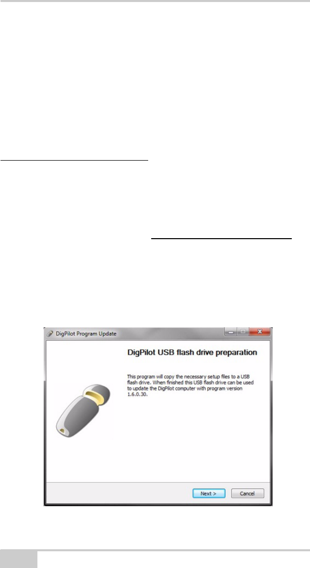
1. To download the “X-22_Update.exe” program onto your
computer, laptop or workstation using Windows, click the link to
the latest program version on www.topconpositioning.com .
Contact your dealer if you have not been given a username and
password.
2. Insert a USB flash drive into the computer.
3. Run the “X-22_Update.exe” program.
4. Click Next.
Figure 1-1. Updating the X-22 Software.
Introduction
P/N 7010-1020 1-3
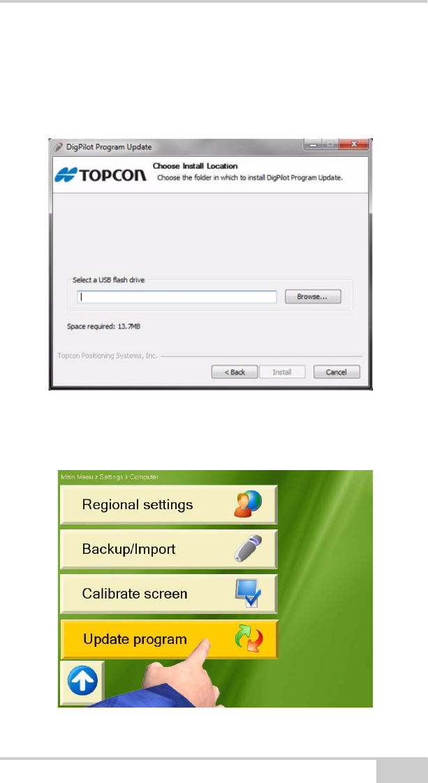
5. Click Browse..., and select the location of USB flash drive. Then,
click Install to allow the program to copy the necessary files to
the USB flash drive, after it checks for enough free space.
When the program is finished, you have the option of reading the
release notes.
Figure 1-2. Updating the X-22 Software.
6. Plug the memory stick into the X-22 Display, and select Main
menu Setup Hardware Computer Update software.
Figure 1-3. Updating the X-22 Software.

X-22 User’s Manual
Notes:
1-4
P/N 7010-1020
Chapter 2
2-1
Getting Acquainted
The following chapter describes the basic features of the X-22
excavator indicate system software.
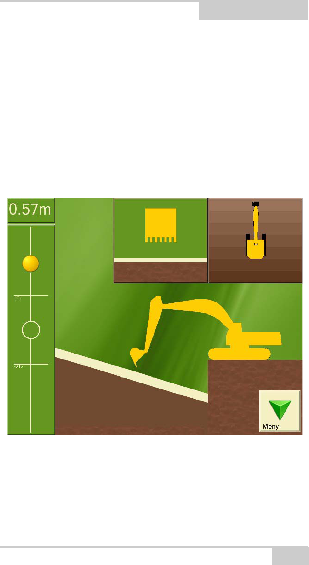
The Digging Window
Figure 2-1. Digging Window
In the Digging Window, you will find all the information you need
for digging. You can also choose what you would like to see
displayed for optimal adaptation of the screen to you and your needs.
This chapter describes what you will see in the Digging Window and
how you can use it.
X-22 User’s Manual
2-2
Target ball
On the left side of the Digging Window (Figure 2-1 on page 2-1) you
will see the Target Ball . This functions as a zoom. As the
bucket tip approaches the digging depth, the ball begins to move.
When the Target Ball is in the center of the circle, the bucket tip is
exactly at the desired digging depth. The two horizontal lines show
the working area.
Bucket Height
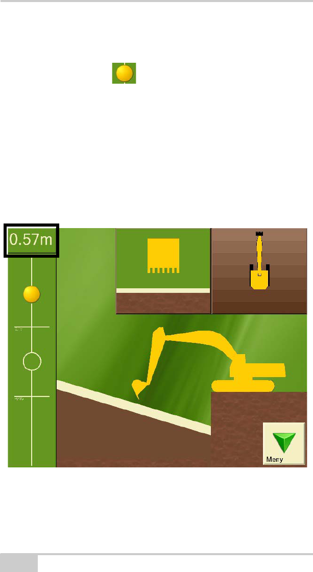
The top left-hand corner of the Digging Window (Figure 2-2)shows
the vertical distance from the measurement point on the bucket tip to
the entered digging depth.
Figure 2-2. Bucket Height
X-22 User’s Manual
2-4
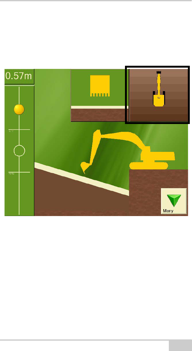
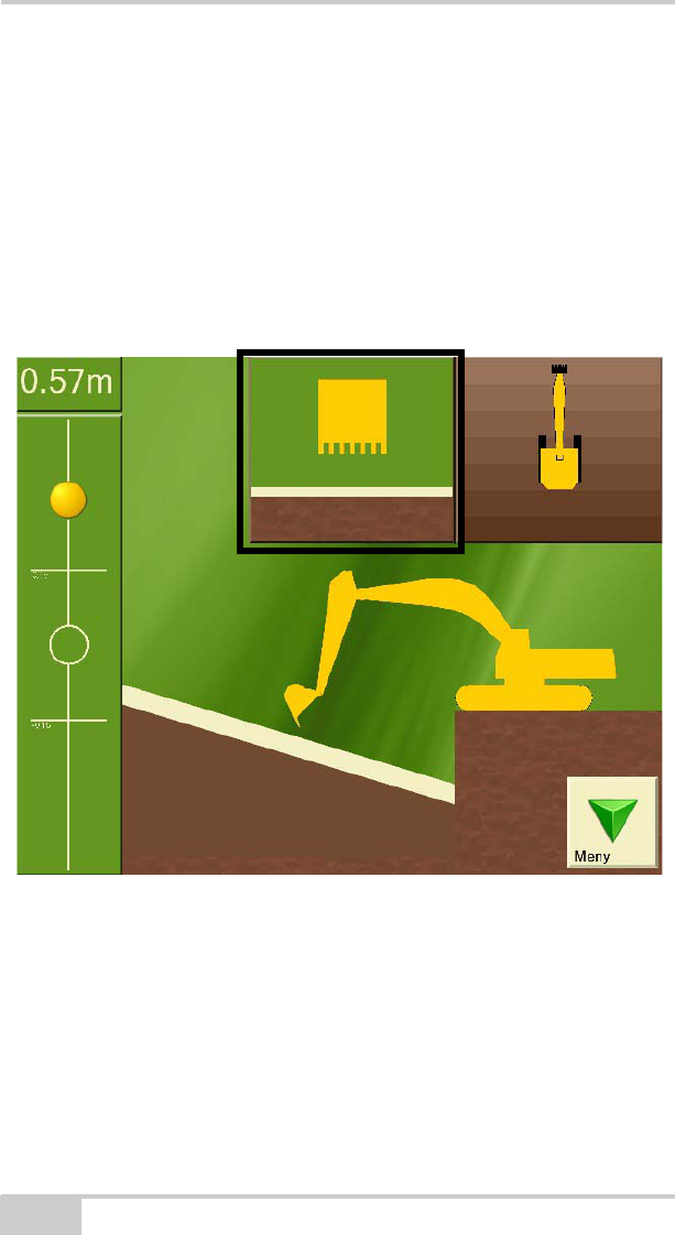
Bucket View
In the top center of the Digging Window (Figure 2-4) the bucket is
displayed as viewed from the driver’s cab with the project below.
This window is particularly useful if you have a tilt bucket and tilt
sensor. It shows both the tilt angle on the bucket and the gradient/
slope of the project perpendicular (90 degrees) to the direction of the
boom. The bucket in the window can also change color to show that
the tilt angle on the bucket is too small, too large or correct for the
project.
Figure 2-4. Bucket View
Getting Acquainted
P/N 7010-1020 2-5
Length
You can also bring up the length from a given point to the bucket tip.
The length will be shown in yellow text under the bucket height.
Length is a separate referencing system which measures the
horizontal distance from the length referencing point to the bucket tip.
The distance is measured with respect to the circle center on the
undercarriage, so that the measured length does not alter as the
superstructure swings around.
This can be very useful when laying pipes for example. Press
Graphics and then choose Visible elements to turn on length
referencing.
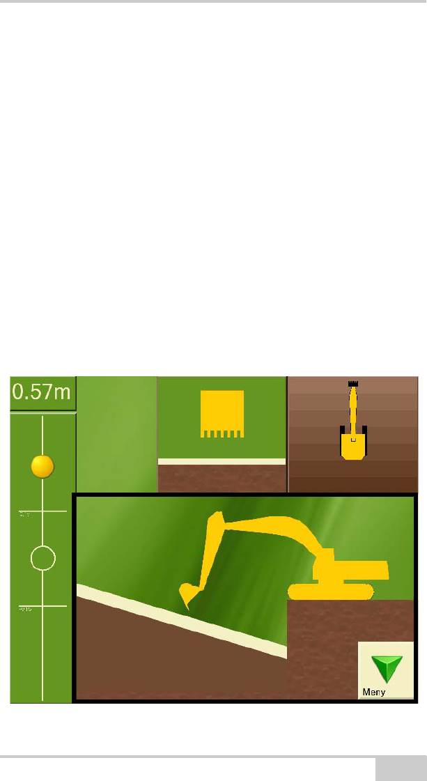
Side View of Machine
Being able to see the excavator from the side during the project is
probably the most important function for you as driver, and is
therefore the main focus in the Digging Window.
Figure 2-5. Side View
X-22 User’s Manual
2-6
Digging Window Buttons
The menu in the Digging Window has a large number of functions
that are just a click away.
Menu
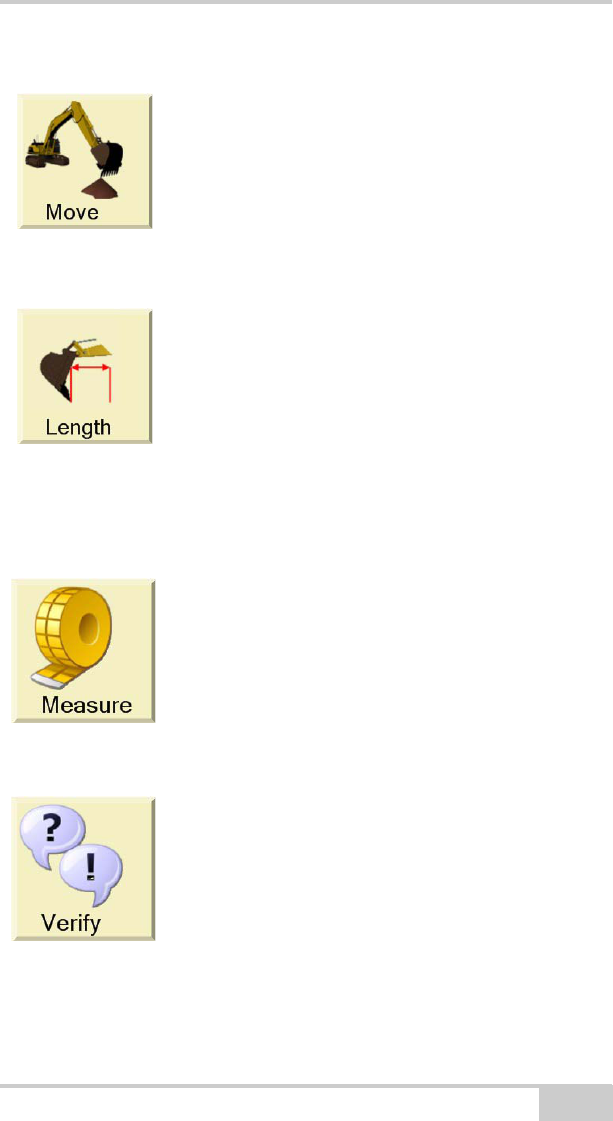
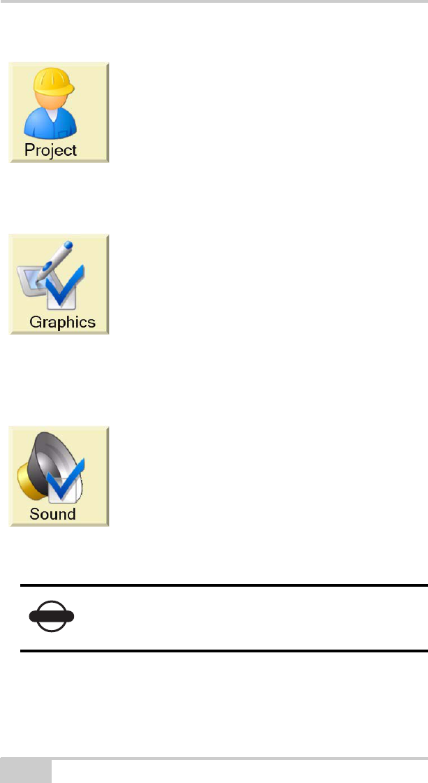
Reference
Benchmark
Laser
Press the reference button to perform a new reference, and follow the
on-screen instructions.
This button opens and closes the Menu.
If you have chosen benchmark as your
referencing method, the reference button will
show the image of a bucket.
If you have chosen laser as your referencing
method, the reference button will show the
image of a laser.
Getting Acquainted
P/N 7010-1020 2-7
Swap Point
Length Referencing
Measure
Verify
Press this button (Move) to use the swap point
function and follow the on-screen instructions.
Place the bucket tip on the reference point and
press this button to start measuring the
horizontal distance from the reference point to
the bucket tip.
This button only appears on the Menu when
length referencing is turned on. Press Graphics
and then choose Visible elements to turn on
length referencing.
Place the bucket tip on the reference point and
press this button to start measuring length,
height, distance and gradient/slope from the
reference point. Press the button once more to
return to the project you are working on.
Pressing this button gives you access to a
procedure which lets you verify whether X-22 is
measuring accurately or not.
If it is not doing so, you can also press Verify,
and select Troubleshooting to identify and
correct any errors.
X-22 User’s Manual
2-8
Work/Project
Graphical Settings
Sound Settings
Press this button to view and alter settings on the
project you are working on. If you wish to start a
new project, this can also be done here.
By pressing this button you can change what is
displayed in the Digging Window and how it is
displayed.
Press this button to change when X-22 will give
a sound signal during digging. The settings for
the height alarm are also located here.
NOTICE
The sound integrated in X-22 is very quiet. External
beeper with a loud sound can be purchased from
your dealer.

Getting Acquainted
P/N 7010-1020 2-9
Types of Work/Projects
X-22 allows you to select the following types of work:
• Flat plane
•Single slope
•Dual slope
•Trench
• Profile
• Channel
• Embankment
• Bucket-defined slope
The type of work is also called a project. The following sections
contain a description of the different projects and what settings need
to be entered.
X-22 User’s Manual
2-10
Flat Plane
Figure 2-6. Flat Plane Surface
A flat plane is a horizontal surface without gradient in any direction.
This means you only need to set two things in X-22:
• The referencing method
• The reference height (vertical distance from reference point to
digging depth)
NOTICE
In flat-plane digging the Digging Window does not
show the machine from above. On a flat plane the
vertical distance from the bucket tip to the digging
depth is the same whatever direction the
superstructure is facing.
Getting Acquainted
P/N 7010-1020 2-11
Single Slope
Figure 2-7. Single Slope Surface
A single slope is a surface with a gradient in one defined direction. In
X-22 you must set the following to work on single slopes:
• The referencing method
• The reference height (vertical distance from reference point to
digging depth)
• The gradient/slope
• Direction of gradient/slope (if compass is turned on)
X-22 User’s Manual
2-12
Dual Slope
Figure 2-8. Dual Slope Surface
A dual slope is a surface with a gradient both lengthways and
sideways. In X-22 you must set the following to work on dual slopes:
• The referencing method
• The reference height (vertical distance from reference point to
digging depth)
• Gradient/slope in lengthways direction
• Gradient/slope to the side
• Direction of gradient/slope in lengthways direction (if compass is
turned on)
NOTE
If you enter the sideways gradient as zero, the
project will be the same as a single slope.
Getting Acquainted
P/N 7010-1020 2-13
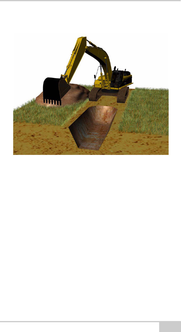
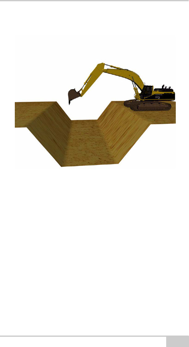
Trench
Figure 2-9. Trench
A trench is a single slope of limited width. The limitation lies in the
width of the trench base and the walls sloping up from the base. A
trench has the following settings:
• The referencing method
• The reference height (vertical distance from reference point to
trench bottom)
• Gradient/slope in lengthways direction
• Width of trench
• Gradient/slope of trench walls
• Direction of gradient/slope in lengthways direction (if compass is
turned on)
X-22 User’s Manual
2-14
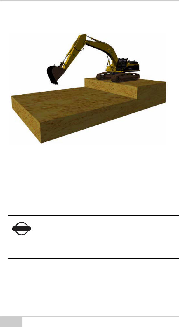
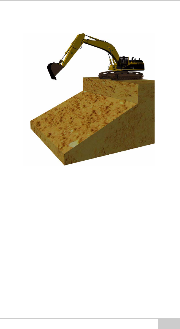
Profile
Figure 2-10. Profile
A profile consists of two horizontal surfaces of different height with a
single slope between them. In X-22 you must set the following to
work on a profile:
• The referencing method
• The reference height (vertical distance from reference point to
digging depth)
• Gradient/slope in lengthways direction
• Height from starting point to base of profile
• Direction of gradient/slope in lengthways direction (if compass is
turned on)
Getting Acquainted
P/N 7010-1020 2-15
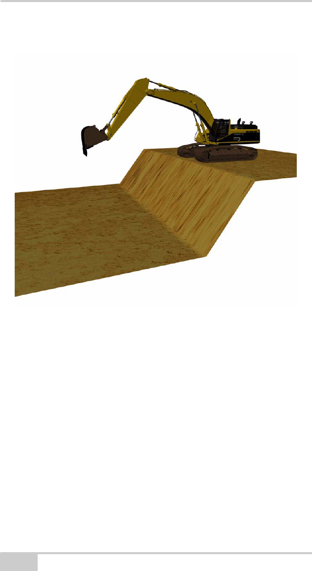
Channel
Figure 2-11. Channel Surface
A channel consists of three horizontal surfaces with single slopes
between them as shown on the illustration opposite, and has the same
gradient on both sides of the channel base. With a channel the
following settings must be entered:
• The referencing method
• The reference height (vertical distance from reference point to
digging depth)
• Gradient/slope in lengthways direction
• Length of channel base
• Height from starting point to base of channel
• Direction of gradient/slope in lengthways direction (if compass is
turned on)

X-22 User’s Manual
2-16
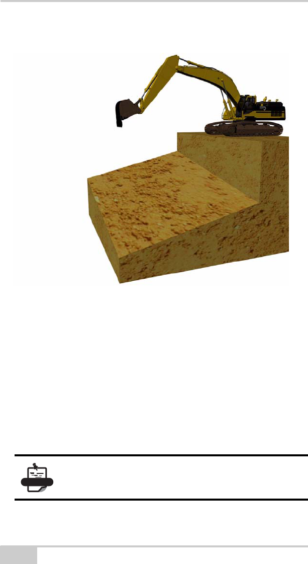
Embankment
Figure 2-12. Embankment Surface
An embankment consists of three horizontal surfaces with single
slopes between them as shown on the illustration opposite, and has
the same gradient on both sides of the embankment top. With an
embankment the following settings must be entered:
• The referencing method
• The reference height (vertical distance from reference point to
digging depth)
• Gradient/slope in lengthways direction
• Length of top of embankment
• Height from starting point to top of embankment
• Direction of gradient/slope in lengthways direction (if compass is
turned on)
Getting Acquainted
P/N 7010-1020 2-17
Bucket-defined
Figure 2-13. Bucket-defined Single Slope Surface
Bucket-defined is used to indicate a single slope using the bucket tip.
This can be useful, for instance when forming a single slope up to the
foundations of a garage.
By referencing the bucket tip to two different points, X-22 will
calculate the gradient, direction of gradient and digging depth and
store these settings in the same way as for a single slope.
NOTICE
Do not rotate the superstructure until you have
referenced both points.

X-22 User’s Manual
Notes:
2-18

P/N 7010-1020
Chapter 3
3-1
X-22 Setup
The following chapter describes how to setup the X-22 software.
Work/Project Settings
Many of the settings entered are the same for the different projects.
Selecting a new project in X-22 guides you through the setup
procedure for these settings using images and text.
This chapter also gives a detailed description of the most important
project settings.
Reference Height
The reference height is the vertical distance from the reference to the
digging depth. If you use a rotating laser for referencing, the laser
plane will be the reference and if you use the bucket tip for
referencing, the benchmark you place the bucket tip on will be the
reference.
You can use the reference height actively when working on a project.
Say you have set the reference height to 1.0 m and have finished
levelling out a site foundation. If your next task is to lay 10
centimeters of crushed stones on the foundation base, you can change
NOTICE
Notice that the reference height will be positive if
the digging height lies below the reference. A
reference height of 1.0 m (3.28 ft.) will thus result
in a digging depth of 1.0 m (3.28 ft.) below the
reference.

X-22 User’s Manual
3-2
the reference height to 0.9 m and use X-22 to check that the layer of
crushed stones has the correct height/thickness.
If you have been given the heights as elevations and have benchmarks
at a particular elevation, you can use X-22’s integral calculator to
work out the reference height.
Gradient/Slope in Lengthways
Direction
This is the gradient in the direction of the boom when Direction of
slope is entered.
Gradient/Slope to the Side
This applies only to Dual slope and is the gradient perpendicular (90
degrees) to the lengthways direction. For all other projects, the
gradient/slope to the side is zero.
Direction of Slope
This is the lengthways direction of the slope and is indicated by
pointing the boom in the lengthways direction of the slope. When you
press OK on the screen, X-22 stores this direction using the compass.
Referencing
X-22 always knows where the bucket tip is in relation to the rotation
center of the undercarriage, but in order to know where the rotation
center and thus the bucket tip is in relation to the project, X-22 must
be referenced. This is done with a benchmark or a rotating laser.
NOTICE
If the excavator is standing in loose material, the
machine may creep. X-22 will not notice this and
you should therefore re-reference if the machine is
creeping a great deal.
X-22 Setup
P/N 7010-1020 3-3
Once you have created a new project you are automatically invited to
reference when you go into the Digging Window. To perform a new
reference, press Reference in the Digging Window menu.
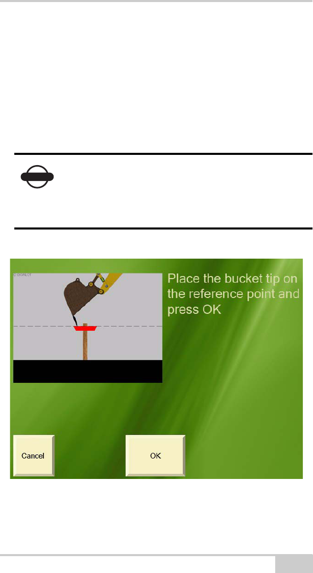
Referencing with Benchmark
A benchmark is a point with a known height in relation to the digging
depth of your current project.
Figure 3-1. Benchmark Reference
Place the bucket tip on the benchmark, and press OK.
NOTICE
If you have chosen Profile, Channel or
Embankment, the benchmark must also have a
known position in relation to the project. See the
screen images for the current project for further
details.
X-22 User’s Manual
3-4
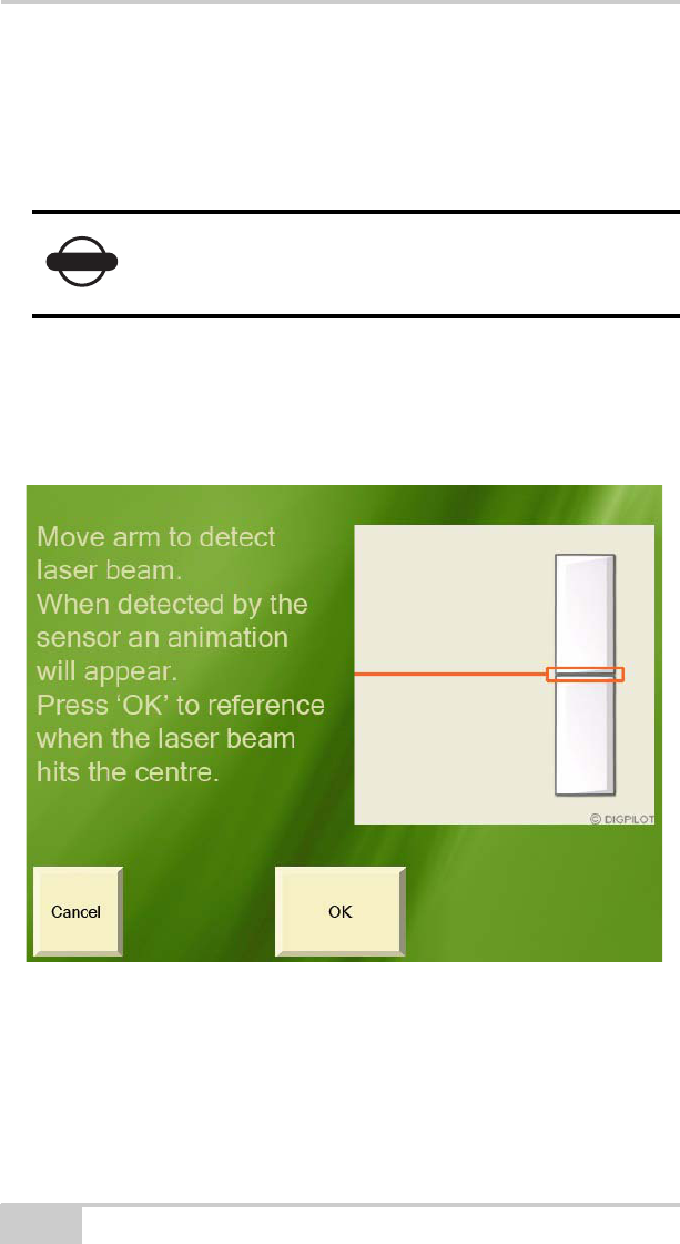
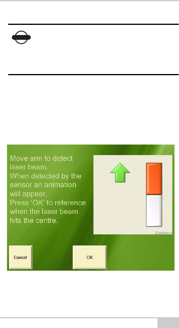
Referencing with Laser
X-22 can also be referenced by detecting the laser ray from a rotating
laser with the laser receiver on the arm sensor.
During referencing, the screen will show where the laser ray has hit
the laser receiver.
Figure 3-2. Laser Reference
Press OK when the laser ray touches the center point.
NOTICE
The laser must be set with exactly the same
gradient/slope and direction as entered for the
project in X-22.
X-22 Setup
P/N 7010-1020 3-5
To find the laser plane as quickly as possible, you can first move the
arm relatively quickly through the area you expect to find the laser
ray in, while simultaneously watching the screen for a hit. When the
laser ray hits its target, go back to the correct height and adjust until
the laser ray touches the center.
Figure 3-3. Laser Reference
NOTICE
The advantage of a rotating laser is that it can cover
large areas with very high accuracy. You avoid
having to use many benchmarks and avoid the risk
of losing accuracy when moving the excavator.
Contact your dealer for offers of X-22 quality
lasers.

X-22 User’s Manual
3-6
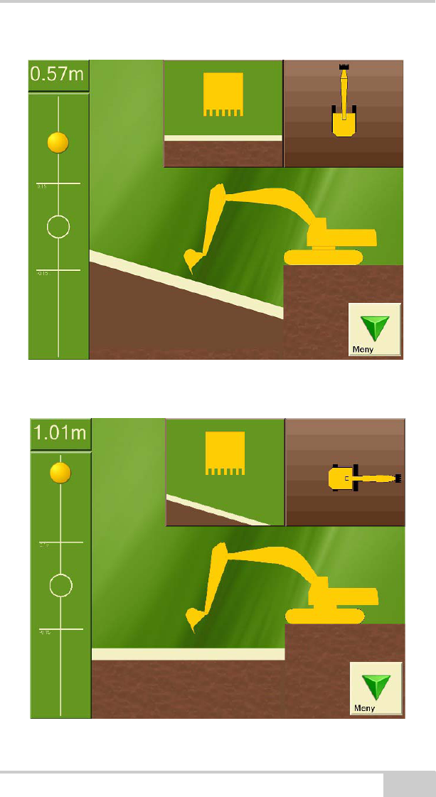
Digging Slopes
All projects except Flat plane include surfaces with a slope.
The gradient/slope is entered in X-22 as a percentage (%), unless
Bucket-defined project is selected. If the gradient/slope has been
specified as a ratio (e.g. 1:8) or in degrees (e.g. 12.5) you can use X-
22’s integral calculator to translate these values into percentages.
Enter the direction of the slope by pointing the boom in the
lengthways direction of the slope.
This is illustrated by a single slope in Figure 3-4 on page 3-7. In this
image, the superstructure is in line with a single slope of 30%
gradient.
In Figure 3-5 on page 3-7, the superstructure has rotated through 90
degrees. As can be seen from the images, the gradient/slope in the
boom direction displayed under the machine changes from 30% to
0% (zero).
NOTICE
A slope has the gradient you entered, in the
lengthways direction entered. Using its compass, X-
22 constantly calculates the gradient in the boom
direction as the superstructure swings around. This
applies to all projects with a slope.
X-22 Setup
P/N 7010-1020 3-7
Figure 3-4. Example of 30% Single Slope in Digging Window
Figure 3-5. Example of 0% Single Slope in Digging Window

X-22 User’s Manual
3-8
Moving the Undercarriage
When you have referenced and finished digging at the point where
the undercarriage is standing and need to move to a new location, you
will need to inform X-22. The following describes three ways you can
do this.
Option 1: New Reference
After moving the undercarriage to a new position you can re-
reference to a benchmark or laser plane.
Option 2: Retain the Same Height
If you have been digging down to the desired depth, you can continue
referencing this digging depth instead of the benchmark or laser plane
you started with. You can do this be altering the reference height in
the project to zero, selecting benchmark as the referencing method
and then referencing the bucket tip on the excavated area after
moving the machine.
X-22 Setup
P/N 7010-1020 3-9
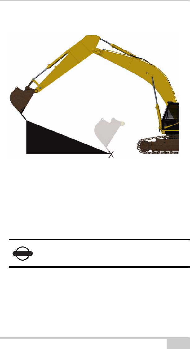
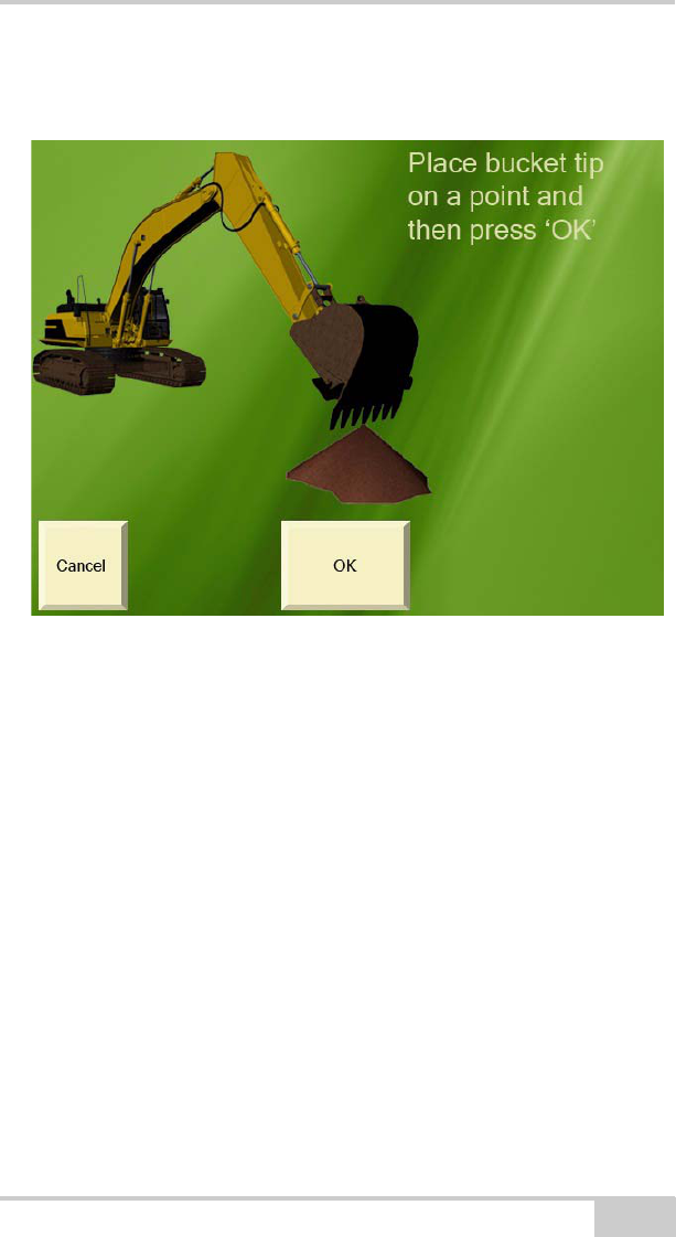
Option 3: Swap Point Function
Figure 3-6. Swap Point Function
The swap point function is available for projects Flat plane, Single
slope and Dual slope. Before you move the undercarriage, place the
bucket tip on a point which can also be reached from the place you
will be moving the undercarriage to. Press “OK” on the screen. Move
the undercarriage and position the bucket tip on the same point. Press
“OK” on the screen again.
Graphical Settings
By pressing Graphics you access a menu on which you can choose
the appearance of the Digging Window in order to adapt it optimally
to you and your needs at any time.

X-22 User’s Manual
3-10
Measurement Point of Bucket
Here you can choose whether to use the middle of the bucket tip, or
the left or right bucket tip as reference point.
Visible Elements
Here you can select which elements are to be shown in the Digging
Window.
Brightness of Digging Window
X-22 has a so-called transreflective screen to give you the best
possible picture when sunlight is directly on the screen. If it is dark
outside and you find the light from the screen too bright, you can dim
it here. Note that it takes approx. 10 seconds to open the Digging
Window while the screen is being dimmed.
Angular Difference for Bucket Warning
You can use this function if you have a tilting bucket and tilting
sensor. In the window showing the bucket from the driver’s cab, the
color of the bucket will change to show that the sideways angle of the
bucket blade is too large, too small or correct for the project. Here
you can enter how large an angular difference you will accept before
the bucket changes colour.
Working Area
The size of the working area determines when the target ball will start
to move and when the “Color warning” will be given. By increasing
the size of the working area you make the target ball less sensitive.
NOTICE
The bucket measurement point is used everywhere
in X-22 where you are asked to use the bucket tip.

X-22 Setup
P/N 7010-1020 3-11
Focus
Here you can choose whether you want the excavator undercarriage
to be stationary while you work or if you want the bucket to remain
stationary while the rest of the excavator and the project move
around.
Color Warning
Here you can select whether X-22 will give you a color warning when
the measurement point on the bucket tip is above or below the
indicated working area. You can choose between a color change on
the background to the screen, to the whole excavator or just the
bucket.
Size of Excavator
Here you can select how much space the excavator will take up on the
screen by increasing or reducing its size.
Position of Excavator
Here you can move the excavator around the screen.
Appearance of Excavator
Here you can select how the excavator will look from the side.
Change the appearance to a small machine if you have a small
excavator with the boom fixed in front of the driver's cab.
NOTICE
If X-22 is correctly installed, it will measure to an
accuracy of one centimeter on a normal excavator.
The size of the working area will not affect
measurement accuracy.
X-22 User’s Manual
3-12
Sound Settings
Sound signals can be a useful aid in addition to the screen display.
Here you can decide whether you want a sound signal when the
measurement point on the bucket tip is in or under the working area.
The height alarm also has a sound signal.
Height Alarm
The height alarm will warn you if the top of the arm or bucket is over
a certain height above the underside of the tracks. To turn the height
alarm on, you need to enter two extra excavator dimensions and
indicate the alarm height.
Using the Compass
In order to make full use of X-22 when excavating sloping projects, it
is essential that the compass gives an accurate measurement. It is
therefore important that the compass is well calibrated.
However, sometimes the compass may not give an accurate reading
even when the undercarriage is level. The greater the gradient/slope
in the project, the greater the error in bucket height will be if the
compass is measuring incorrectly.
NOTICE
Note that the height alarm is indicated in relation to
the underside of the excavator tracks and not in
relation to the project.
NOTICE
Note that the compass is at its most accurate when
the undercarriage is horizontal.

X-22 Setup
P/N 7010-1020 3-13
When excavating across large slopes you should therefore consider
turning off the compass and keeping track of the direction yourself.
You can turn off the compass by selecting Main menu Setup
Hardware Sensors and marking the PitchRollCompass sensor.
Select Details. Then select Compass on and press Change.
Speed of Sensors
Excavators may vibrate a great deal or very little, depending on rpm,
size, age, make etc. and this will affect the sensors’ angular
measurements. X-22 has been designed to ensure the sensors give the
optimum in stable, quick and accurate angular measurements in all
types of excavators.
It is therefore possible to alter the sensitivity and damping of the
sensors for the best possible match with your excavator. At the
factory the sensors are set with the aim of being stable when the
excavator is stationary, but reacting immediately when the machine
moves.
To make changes to this, select Main Menu Setup Hardware
Sensors, and press Sensitivity.
Sensitivity
Sensitivity indicates how strong the vibrations in the excavator must
be before X-22 interprets this as a movement of the machine.
By increasing the sensitivity, smaller vibrations in the machine may
be interpreted as a movement of the machine.
Reducing the sensitivity means that it will take larger vibrations to be
interpreted as a movement of the machine.

X-22 User’s Manual
3-14
Damping
Damping indicates how much the angular measurements will be
filtered when the excavator is stationary. Filtering makes the angular
measurements stable and accurate despite vibrations.
By increasing the damping, X-22 will react more slowly to small and
limited movements in the machine.
By reducing the damping, X-22 will react more quickly to small and
limited movements in the machine.
Damping is set high at the factory and can thus be probably adjusted
downwards.

P/N 7010-1020
Chapter 4
4-1
Troubleshooting
In this section you will find answers to the following questions:
The X-22 Display is not responding, what should I do?......... page 4-1
The sensors are not responding, what should I do?................page 4-1
A sensor is damaged, what should I do?...............................page 4-1
How do I recalibrate a sensor?..............................................page 4-1
The system is not measuring accurately, what should I do?....page 4-2
The compass is measuring incorrectly, what should I do?......page 4-2
The laser sensor is not working, what should I do?...............page 4-2
The X-22 Display is not responding, what
should I do?
Most X-22 problems can be solved by turning the X-22 Display off
and on.
The sensors are not responding, what should I
do?
If you are having problems making contact with the sensors, proceed
as follows: Turn the X-22 Display off and put all the sensors in the
charger for a few minutes. The sensors will then be reset while they
are being charged. Take all the sensors out of the charger and turn the
X-22 Display back on.
A sensor is damaged, what should I do?
You can obtain a new sensor by contacting your dealer. Delete the
damaged sensor from the X-22 Display before entering the new one.

X-22 User’s Manual
4-2
How do I recalibrate a sensor?
If you have already calibrated the sensors and want to recalibrate one,
proceed as follows: Select Main menu Setup Hardware
Sensors and highlight the sensor you want to calibrate. Select
Details. Then select Calibrated and press Change.
The system is not measuring accurately, what
should I do?
If the system is not measuring accurately, a dimension or calibration
value is probably wrong. Select Verify from the menu in the
Digging Window, and press Troubleshooting. X-22 will then help
you identify the problem and rectify it. Follow the on-screen
instructions.
The compass is measuring incorrectly, what
should I do?
The compass in the PitchRollCompass sensor is magnetic and has to
be calibrated in order to measure correctly.
Therefore try recalibrating the compass to see if this helps. Select
Main Menu Setup Hardware Sensors
PitchRollCompass Details. Then select Calibrated, and press
Change.
If you want to check how well the compass is calibrated, you can
select Main MenuSetupHardwareSensors
PitchRollCompassVerify. When the machine is stationary and the
superstructure is rotated, the compass measurements should ideally
form a perfect circle with the center at the origin.
In certain special circumstances the magnetic compass can be
disrupted so much that it should not be used. In this situation the
heading on the screen can change even if the machine is at a complete
standstill.
If this happens, the compass should be turned off. Select Main menu
Setup Hardware Sensors and highlight the
PitchRollCompass sensor. Select “Details”. Then select “Compass

Troubleshooting
P/N 7010-1020 4-3
on” and press “Change”. All the software functions that use the
heading measurements from the compass will now disappear and you
will have to keep track of the heading yourself.
In situations where there are large fluctuations in the magnetic field
around the machine all the time, the compass calibration will not be
able to compensate for the disturbances. An example of such a
situation is if the machine is close to a railway line that is in use:
Trains are surrounded by a strong magnetic field, which will badly
disrupt the compass measurements whenever a train goes past. In this
case the heading displayed on the screen could change even if the
machine is at a complete standstill.
Working in the vicinity of high-voltage cables can also cause
problems for the magnetic compass.
The laser sensor is not working, what should I
do?
The laser sensor may have problems detecting the laser beam in
strong sunlight, particularly if the sun is shining straight into the
photoelectric cell. If this happens, the amount of sunlight hitting the
cell will have to be reduced by turning the sensor away from the sun,
for example.
If the laser sensor is exposed to strobe lighting, a rotating flashing
light or the like, the sensor may be misled into thinking that it has
detected the laser.
If the laser sensor does not respond to the laser beam at all, even at
close range, the photoelectric cell has probably been damaged. In this
case you will have to contact your dealer to have the sensor replaced.

X-22 User’s Manual
Notes:
4-4

P/N 7010-1020
Appendix A
A-1
Specifications
X-22 Sensor
The following section provides specifications for the X-22 Sensor.
Table A-1. X-22 Sensor General Specifications
General Details
Enclosure Xenoy CL 100 Polycarbonate
Resistant to hydraulic fluids, diesel and UV exposure
IP67
Color Topcon Yellow
Dimensions W: 112 mm x H: 48 mm x D: 68 mm
W: 4.4 in. x H: 1.89 in. x D: 2.68 in.
Weight 230g (standard sensor)
0.5 lbs.
Battery Operating time: Up to four weeks with normal use
Material: Lithium-ion polymer
Nominal capacity: 5600mAh
Charging time: Overnight
Expected battery life: Beyond 3 years
Operating
temperature
-20°C to +60°C
-4°F to +140°F
Charging
temperature
+5°C to +35°C
-41°F to +95°F
Storage temperature -20°C to +35°C
-4°F to +95°F
Radio Range: Over 50m (164 ft) line-of-sight
Frequency: 2.4 GHz license-free ISM-band
Proprietary packet radio protocol

X-22 User’s Manual
A-2
X-22 Display
The following section provides specifications for the X-22 Fanless
8.9” WSVGA TFT Multifunctional Touch Panel PC.
Connectors 2 charging pins (6V DC input, no polarity)
Table A-2. X-22 Sensor General Specifications
Display Screen
LCD Size 8.9”
Display Type WSVGA TFT
Resolution 1024 x 600
Color 256K
Pixel Pitch 0.1905mm (H) x 0.189mm (V)
Luminance 220cd/m²
Contrast Ratio 500
Viewing Angle 50 (U), 60 (D), 70 (L), 70 (R)
Response Time 30ms
Backlight LED
Touch Screen 5-Wire Resistive
Light transmission 80%
Touch Interface USB Onboard Touch Interface
System
CPU Onboard AMD Geode LX800 @ 0.9W 500MHz with
128K L2 Cache CPU
Cooling Method Passive CPU Heatsink
System Chipset AMD Geode LX800/ CS5536
Table A-1. X-22 Sensor General Specifications (Continued)

P/N 7010-1020 A-3
System Memory Onboard 512MB DDR Memory
SSD One CF Socket by IDE Secondary Slave Channel
Supports Type I/II Compact Flash Card
Rear Panel I/O
Serial Port 1 x RS-232, 1 x RS-232 or Optional RS-422/ 485
Ethernet 2 x RJ-45 (Realtek RTL8101L LAN)
WIFI Optional USB WiFi 802.11 b/g (Occupies One USB Port)
VGA 1 x DB-15
Audio Line-out, Mic-in
USB 2 x USB 2.0
Mouse & K/B 1 x PS/2 Keyboard Connector
Environment & Mechanical
Color Front Panel Black; Rear Panel Black
Mounting Wall/ Stand/ VESA 75mm x 75mm
Power Input 100 ~ 250Vdc/ 47 ~ 63Hz
Power Output +12Vdc/ 5A (60W)
Operating
Temperature
-10°C ~ 60°C
14°F to +140°F
Storage
Temperature
-20°C ~ 70°C
-4°F to +158°F
Relative Humidity 10% to 95% @ 40°C, Non-condensing
Dimension W: 225mm x H: 139mm x D: 38.9mm
W: 8.86 in. x H: 5.47 in. x D: 1.53 in.
Weight 1.26Kgs (2.78 lbs.)
Table A-2. X-22 Sensor General Specifications (Continued)

X-22 User’s Manual
A-4

P/N 7010-1020
Appendix B
B-1
Safety Warnings
General Warnings
1. Read and become familiar with the machine manufacturer’s
operating instructions, including safety information, before
installing or using your Topcon equipment.
2. Use extreme caution on the jobsite. Working around heavy
construction equipment can be dangerous.
3. DO NOT attach system brackets while the machine is running.
4. DO NOT allow any X-22 system component to limit the visibility
of the operator.
5. Use Ty-wraps, to keep hoses and wires secured and away from
possible wear or pinch points.
6. Use eye protection whenever welding, cutting, or grinding is
being done on the machine.
7. Protect yourself at all times, and wear protective clothing, when
working on or near hydraulic lines. Avoid direct exposure to your
eyes when using laser control.
8. Use appropriate welding precautions and practices when welding.
After welding, all paint all affected areas with a rust inhibitor.
CAUTION
DO NOT stare into the laser beam or view the beam
directly with optical equipment.
WARNING
DO NOT weld near hydraulic lines or on any
equipment when in operation.
X-22 User’s Manual
B-2
9. To prevent vandalism or theft, do not leave removable Topcon
components on the machine at night. Remove the components
each evening and store appropriately in the carrying case.
10. Keep the carrying case dry at all times.
If moisture does enter the carrying case, leave it open and allow it
to thoroughly dry before storing any components.
NOTICE
Disconnect all Topcon system electrical cables
prior to welding on the machine.
NOTICE
All mounting bracket welds must be secure and
strong to prevent sensor equipment from vibrating
excessively or from becoming detached at the weld
during operation.
NOTICE
DO NOT allow moisture to get inside the case.
Moisture trapped in the case can adversely affect
components.
P/N 7010-1020 B-3
Sensor Warnings
DANGER
Never attempt to open the X-22 sensors! Lithium-
Ion batteries can be dangerous if mishandled!
DANGER
Do not incinerate or heat battery pack above 212
degrees fahrenheit (100 degrees celsius). Excessive
heat can cause serious damage and possible
explosion.
WARNING
Tampering with the batteries by end users or non-
factory authorized technicians will void the
battery’s warranty.
• Do not attempt to open the sensors.
• Do not disassemble the sensor.
• Do not charge in conditions different than
specified.
• Do not use other than the specified battery
charger.
• Do not short circuit.
• Do not crush or modify.
X-22 User’s Manual
B-4
Usage Warnings
CAUTION
If this product has been dropped, altered,
transported or shipped without proper packaging, or
otherwise treated without care, erroneous
measurements may occur.
The owner should periodically test this product to
ensure it provides accurate measurements.
Inform Topcon immediately if this product does not
function properly.
CAUTION
Only allow authorized Topcon warranty service
centers to service or repair this product.

P/N 7010-1020
Appendix C
C-1
Regulatory Information
The following sections provide information on this product’s
compliance with government regulations for use.
FCC Compliance
This device complies with Part 15 of the FCC rules. Operation is
subject to the following two conditions:
1. This device may not cause harmful interference, and
2. This device must accept any interference received, including
interference that may cause undesired operation.
This equipment has been tested and found to comply with the limits
for a digital device, pursuant to Part 15 of the FCC rules. These limits
are designed to provide reasonable protection against harmful
interference in residential installations. This equipment generates,
uses, and can radiate radio frequency energy, and if not installed and
used in accordance with the instructions, may cause harmful
interference to radio communications. However, there is no guarantee
that interference will not occur in a particular installation.
If this equipment does cause interference to radio or television
equipment reception, which can be determined by turning the
equipment off and on, you are encouraged to try to correct the
interference by one or more of the following measures:
• Reorient or relocate the receiving antenna.
• Move the equipment away from the receiver.
• Plug the equipment into an outlet on a circuit different from that
to which the receiver is powered.
• Consult the dealer or an experienced radio/television technician
for additional suggestions.

X-22 User’s Manual
C-2
FCC Compliance
This equipment complies with FCC radiation exposure limits set forth
for uncontrolled equipment and meets the FCC radio frequency (RF)
Exposure Guidelines in Supplement C to OET65. This equipment has
very low levels of RF energy that it deemed to comply without
maximum permissive exposure evaluation (MPE). But it is desirable
that it should be installed and operated with at least 20cm and more
between the radiator and person’s body (excluding extremities:
hands, wrists, feet and ankles). This device complies with Part 15 of
the FCC rules. Operation is subject to the following two conditions:
1. This device may not cause harmful interference, and
2. This device must accept any interference received, including
interference that may cause undesired operation.
This equipment has been tested and found to comply with the limits
for a digital device, pursuant to Part 15 of the FCC rules. These limits
are designed to provide reasonable protection against harmful
interference in residential installations. This equipment generates,
uses, and can radiate radio frequency energy, and if not installed and
used in accordance with the instructions, may cause harmful
interference to radio communications. However, there is no guarantee
that interference will not occur in a particular installation.
If this equipment does cause interference to radio or television
equipment reception, which can be determined by turning the
equipment off and on, the user is encouraged to try to correct the
interference by one or more of the following measures:
• Reorient or relocate the receiving antenna.
• Move the equipment away from the receiver.
CAUTION
Any changes or modifications to the equipment not
expressly approved by the party responsible for
compliance could void your authority to operate
such equipment.

P/N 7010-1020 C-3
• Plug the equipment into an outlet on a circuit different from that
to which the receiver is powered.
• Consult the dealer or an experienced radio/television technician
for additional suggestions.
Federal Communication Commission
Declaration of Conformity (DoC) Statement
Model No: HiPer II
CAUTION
Any changes or modifications to the equipment not
expressly approved by the party responsible for
compliance could void your authority to operate
such equipment.
Trade Name Topcon
Responsible Party Topcon Positioning
Systems, Inc.
Address
7400 National Drive,
Livermore, CA 94550
Telephone No +925-245-8300

X-22 User’s Manual
C-4
Canadian Emission Labeling
Requirements
This equipment complies with IC radiation exposure limits set forth
for uncontrolled equipment and meets RSS-102 of the IC radio
frequency (RF) Exposure rules. This equipment has very low levels
of RF energy that it deemed to comply without maximum permissive
exposure evaluation (MPE). But it is desirable that it should be
installed and operated with at least 20cm and more between the
radiator and person’s body (excluding extremities: hands, wrists, feet
and ankles).
1. Operation is subject to the following two conditions: (1) this
device may not cause interference, and (2) this device must
accept any interference, including interference that may cause
undesired operation of the device.
2. To reduce potential radio interference to other users, the antenna
type and its gain should be so chosen that the equivalent
isotropically radiated power (e.i.r.p.) is not more than that
permitted for successful communication.
3. This Class B digital apparatus meets all requirements of the
Canadian Interference-Causing Equipment Regulations.
Cet appareil numérique de la classe B respecte conform a la norme
NMB-003 du Canada.
IC RF Radiation Exposure Statement
This installer of this device must ensure that the antenna is located or
pointed such that it dose not emit RF field in excess of Health Canada
limits for the general population; consult Safety Code 6, obtainable
from Health Canada’s website at www.hc-sc.gc.ca/rpb.
P/N 7010-1020 C-5
Community of Europe
Compliance
The product described in this manual is in compliance with the
R&TTE and EMC directives from the European Community.
European Community Declaration of
Conformity with R&TTE Directive 1999/5/EC
The following standards were applied: (R&TTE Directive 1999/5/EEC)
• EN 301 489-1 V1.8.1 (2008-04)
• EN 301 489-17 V1.3.2 (2008-04)
• EN 300 328 V1.7.1 (2006-10)
• EN 60950-1:2001 + A11:2004
The following CE mark is affixed to the device:
X-22 User’s Manual
C-6
Declaration of Conformity with
Regard to the R&TTE Directive
1999/5/EC
esky
[Czech]
(Topcon) tímto prohlašuje, že tento (HiPer II) je ve
shod se základními požadavky a dalšími píslušnými
ustanoveními smrnice 1999/5/ES.
Dansk
[Danish]
Undertegnede (Topcon) erklærer herved, at
følgende udstyr (HiPer II) overholder de væsentlige
krav og øvrige relevante krav i direktiv 1999/5/EF.
Deutsch
[German]
Hiermit erklärt (Topcon) dass sich das Gerät (HiPer
II) in Übereinstimmung mit den grundlegenden
Anforderungen und den übrigen einschlägigen
Bestimmungen der Richtlinie 1999/5/EG befindet.
Eesti
[Estonian]
Käesolevaga kinnitab (Topcon) seadme (HiPer II)
vastavust direktiivi 1999/5/EÜ põhinõuetele ja
nimetatud direktiivist tulenevatele teistele
asjakohastele sätetele.
English Hereby, (Topcon) declares that this (HiPer II) is in
compliance with the essential requirements and
other relevant provisions of Directive 1999/5/EC.
Español
[Spanish]
Por medio de la presente (Topcon) declara que el
(HiPer II) cumple con los requisitos esenciales y
cualesquiera otras disposiciones aplicables o
exigibles de la Directiva 1999/5/CE.
[Greek]
Français
[French]
Par la présente (Topcon) déclare que l'appareil
(HiPer II) est conforme aux exigences essentielles
et aux autres dispositions pertinentes de la directive
1999/5/CE.
cs
da
de
et
en
es
el
fr
P/N 7010-1020 C-7
Italiano
[Italian]
Con la presente (Topcon) dichiara che questo
(HiPer II) è conforme ai requisiti essenziali ed alle
altre disposizioni pertinenti stabilite dalla direttiva
1999/5/CE.
Latviski
[Latvian]
Ar šo (Topcon) deklar, ka (HiPer II) atbilst
Direktvas 1999/5/EK btiskajm prasbm un citiem ar
to saisttajiem noteikumiem.
Lietuvi
[Lithuanian]
Šiuo (Topcon) deklaruoja, kad šis (HiPer II)
atitinka esminius reikalavimus ir kitas 1999/5/EB
Direktyvos nuostatas.
Nederlan
ds [Dutch]
Hierbij verklaart (Topcon) dat het toestel (HiPer II)
in overeenstemming is met de essentiële eisen en
de andere relevante bepalingen van richtlijn 1999/
5/EG.
Malti
[Maltese]
Hawnhekk, (Topcon) , jiddikjara li dan (HiPer II)
jikkonforma mal-tiijiet essenzjali u ma
provvedimenti orajn relevanti li hemm fid-Dirrettiva
1999/5/EC.
Magyar
[Hungarian]
Alulírott, (Topcon) nyilatkozom, hogy a (HiPer II)
megfelel a vonatkozó alapvetõ követelményeknek
és az 1999/5/EC irányelv egyéb elõírásainak.
Polski
[Polish]
Niniejszym, (Topcon) , deklaruj, e (HiPer II)
spenia wymagania zasadnicze oraz stosowne
postanowienia zawarte Dyrektywie 1999/5/EC.
Portuguê
s
[Portugues]
(Topcon) declara que este (HiPer II) está conforme
com os requisitos essenciais e outras disposições da
Directiva 1999/5/CE.
Slovensk
o
[Slovenian]
(Topcon) izjavlja, da je ta (HiPer II) v skladu z
bistvenimi zahtevami in ostalimi relevantnimi doloili
direktive 1999/5/ES.
Slovensy
[Slovak]
(Topcon) týmto vyhlasuje, že (HiPer II) spa
základné požiadavky a všetky príslušné ustanovenia
Smernice 1999/5/ES.
it
la
li
nl
mt
hu
pl
pt
sl
da
X-22 User’s Manual
C-8
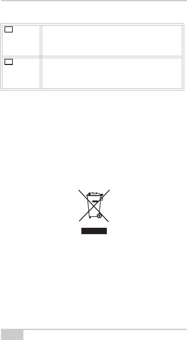
WEEE Directive
Following information is for EU-member states only:
The use of the symbol below indicates that this product may not be
treated as household waste. By ensuring this product is disposed of
correctly, to help prevent potential negative consequences for the
environment and human health, which could otherwise be caused by
inappropriate waste handling of this product. For more detailed
information about the take-back and recycling of this product, please
contact a supplier where you purchased the product or consult.
Suomi
[Finnish]
(Topcon) vakuuttaa täten että (HiPer II) tyyppinen
laite on direktiivin 1999/5/EY oleellisten
vaatimusten ja sitä koskevien direktiivin muiden
ehtojen mukainen.
Svenska
[Swedish]
Härmed intygar (Topcon) att denna (HiPer II) står
I överensstämmelse med de väsentliga
egenskapskrav och övriga relevanta bestämmelser
som framgår av direktiv 1999/5/EG.
fi
sv

P/N 7010-1020
Appendix D
D-1
Warranty Terms
TPS laser and electronic positioning equipment are guaranteed
against defective material and workmanship under normal use and
application consistent with this Manual. The equipment is guaranteed
for the period indicated, on the warranty card accompanying the
product, starting from the date that the product is sold to the original
purchaser by TPS’ Authorized Dealers.1
During the warranty period, TPS will, at its option, repair or replace
this product at no additional charge. Repair parts and replacement
products will be furnished on an exchange basis and will be either
reconditioned or new. This limited warranty does not include service
to repair damage to the product resulting from an accident, disaster,
misuses, abuse or modification of the product.
Warranty service may be obtained from an authorized TPS warranty
service dealer. If this product is delivered by mail, purchaser agrees to
insure the product or assume the risk of loss or damage in transit, to
prepay shipping charges to the warranty service location and to use
the original shipping container or equivalent. A letter should
accompany the package furnishing a description of the problem and/
or defect.
The purchaser’s sole remedy shall be replacement as provided above.
In no event shall TPS be liable for any damages or other claim
including any claim for lost profits, lost savings or other incidental or
consequential damages arising out of the use of, or inability to use,
the product.
1. The warranty against defects in a Topcon battery, charger, or cable is 90
days.

X-22 User’s Manual
Notes:
D-2

Topcon Positioning Systems, Inc.
7400 National Drive, Livermore, CA 94550
800∙443∙4567 www.topconpositioning.com
ISO 9001:2000
FM 68448
X-22 User’s Manual
P/N: 7010-1020 Rev A 06/11
©2011 Topcon Positioning Systems, Inc. All rights reserved. No unauthorized duplication.