Topcon America 80501WL GNSS RECEIVER SYSTEM User Manual GRS func 081117
Topcon America Corporation GNSS RECEIVER SYSTEM GRS func 081117
Contents
- 1. Users Manual 1
- 2. Users Manual 2
- 3. Users Manual 3
Users Manual 1

DRAFAFT Chapter 1
1
Introduction
The GRS receiver is a single-frequency, GPS+GLONASS L1 L2receiver and hand-held controller built to be the
most advanced, compact, and portable receiver for the GIS surveying market. An integrated electronic compass and
digital camera make the GRS an all-purpose, GIS field mapping unit.
The GRS receiver is a multi-function, multi-purpose receiver intended for precision markets. Precision markets
means markets for equipment, subsystems, components and software for surveying, construction, commercial
mapping, civil engineering, precision agriculture and land-based construction and agriculture machine control,
photogrammetry mapping, hydrographic and any use reasonably related to the foregoing.
The GRS provides the functionality, accuracy, availability, and integrity needed for fast and easy data collection.
Principles of Operation
Surveying with the right GPS receiver can provide users accurate and precise positioning, a requirement for any
surveying project.
This section gives an overview of existing and proposed Global Navigation Satellite Systems (GNSS) and receiver
functions to help you understand and apply basic operating principles, allowing you to get the most out of your
receiver.
GNSS Overview
Currently, the following three global navigation satellite systems (GNSS) offer line-of-site radio navigation and
positioning, velocity, and time services on a global, all-weather, 24-hour scale to any user equipped with a GNSS
tracking receiver on or near the Earth’s surface:
• GPS – the Global Positioning System maintained and operated by the United States Department of Defense. For
information on the status of this system, visit the US Naval Observatory website (http://tycho.usno.navy.mil/) or
the US Coast Guard website (http://www.navcen.uscg.gov/).
• GLONASS – the Global Navigation Satellite System maintained and operated by the Russian Federation
Ministry of Defense. For information on the status of this system, visit the Ministry of Defense website
(http://www.glonass-center.ru/frame_e.html).
• GALILEO – an upcoming global positioning system maintained and operated by Galileo Industries, a joint
venture of several European space agencies working closely with the European Space Agency. Unlike GPS and
GLONASS, this is a civil endeavor and is currently in the development and validation stage. For information on
the status of this system, visit the Galileo Industries website (http://www.galileo-industries.net).
Despite numerous technical differences in the implementation of these systems, satellite positioning systems have
three essential components:
• Space – GPS, GLONASS, and GALILEO satellites orbit approximately 12,000 nautical miles above Earth and
are equipped with a clock and radio. These satellites broadcast digital information (ephemerides, almanacs,
time&frequency corrections, etc.).
• Control – Ground stations located around the Earth that monitor the satellites and upload data, including clock
corrections and new ephemerides (satellite positions as a function of time), to ensure the satellites transmit data
properly.

Introduction
GRS Operator’s Manual
2
• User – The community and military that use GNSS receivers and the corresponding satellites to calculate
positions.
Calculating Absolute Positions
When calculating an absolute position, a stationary or moving receiver determines its three-dimensional position
with respect to the origin of an Earth-Center Earth-Fixed coordinate system. To calculate this position, the receiver
measures the distance (called pseudo-ranges) between it and at least four satellites. The measured pseudo-ranges are
corrected for clock differences (receiver and satellites) and signal propagation delays due to atmospheric effects.
The positions of the satellites are computed from the ephemeris data transmitted to the receiver in navigation
messages. When using a single satellite system, the minimum number of satellites needed to compute a position is
four. In a mixed satellite scenario (GPS, GLONASS, GALILEO), the receiver must lock onto at least five satellites
to obtain an absolute position.
To provide fault tolerance using only GPS or only GLONASS, the receiver must lock onto a fifth satellite. Six
satellites will provide fault tolerance in mixed scenarios.
Calculating Differential Positions
DGPS, or Differential GPS, typically uses the measurements from two or more remote receivers to calculate the
difference (corrections) between measurements, thus providing more accurate position solutions.
With DGPS, one receiver is placed at a known, surveyed location and is referred to as the reference receiver or base
station. Another receiver is placed at an unknown, location and is referred to as the remote receiver or rover. The
reference station collects the range measurements from each GPS satellite in view and forms the differences
(corrections) between the calculated distance to the satellites and the measured pseudo-ranges to the satellites.
These corrections are then built up to the industry standard (RTCM or various proprietary standards) established for
transmitting differential corrections and broadcast to the remote receiver(s) using a data communication link. The
remote receiver applies the transmitted DGPS corrections to its range measurements of the same satellites.
Using this technique, the spatially correlated errors—such as satellite orbital errors, ionospheric errors, and
tropospheric errors—can be significantly reduced, thus improving the position solution accuracy of the GPS.
A number of differential positioning implementations exist, including post-processing surveying, real-time
kinematic surveying, maritime radio beacons, geostationary satellites (as with the OmniSTAR service), and the
wide area augmentation system (WAAS) service.
The real-time kinematic (RTK) method is the most precise method of real-time surveying. RTK requires at least two
receivers collecting navigation data and communication data link between the receivers. One of the receivers is
usually at a known location (Base) and the other is at an unknown location (Rover). The Base receiver collects
carrier phase measurements, generates RTK corrections, and sends this data to the Rover receiver. The Rover
processes this transmitted data with its own carrier phase observations to compute its relative position with high
accuracy, achieving an RTK accuracy of up to 1 cm horizontal and 1.5 cm vertical.
Essential Components for Quality Surveying
Achieving quality position results requires the following elements:
• Accuracy – The accuracy of a position primarily depends upon the satellite geometry (Geometric Dilution of
Precision, or GDOP) and the measurement (ranging) errors.
– Differential positioning (DGPS and RTK) strongly mitigates atmospheric and orbital errors, and
counteracts Selective Availability (SA) signals the US Department of Defense transmits with GPS signals.
– The more satellites in view, the stronger the signal, the lower the DOP number, the higher positioning
accuracy.

3
• Availability – The availability of satellites affects the calculation of valid positions. The more visible satellites
available, the more valid and accurate the position. Natural and man-made objects can block, interrupt, and
distort signals, lowering the number of available satellites and adversely affecting signal reception.
• Integrity – Fault tolerance allows a position to have greater integrity, increasing accuracy. Several factors
combine to provide fault tolerance, including:
– Receiver Autonomous Integrity Monitoring (RAIM) detects faulty GPS and GLONASS satellites and
removes them from the position calculation.
– Five or more visible satellites for only GPS or only GLONASS; six or more satellites for mixed scenarios.
– Wide Area Augmentation Systems (WAAS, EGNOS, etc.) creates and transmit, along with DGPS
corrections, data integrity information (for example, satellite health warnings).
– Current ephemerides and almanacs.
Conclusion
This overview simply outlines the basics of satellite positioning. For more detailed information, visit the TPS
website.
GRS Overview
The GRS is a fully integrated hand-held controller and GPS+ receiver. Included in the system is an electronic
compass and digital camera.
The hand-held controller component of the GRS
includes the Windows® Mobile operating system and color LCD touch screen. Integrated Bluetooth® /Cell phone
modem (option)wireless technology allows this system to be a cable-free controller/receiver for maximum
portability. The rugged casing is durable and built for rugged use.
As a field controller, the GRS can run a full suite of field software for working with total stations and RTK GPS
systems.
The GPS+ receiver component of the GRS
can receive and process GPS+GLONASS L1/L2 signals improving the accuracy of your survey points and positions.
The GPS+ features of the receiver combine to provide a positioning system accurate for any survey. Several other
features, including multipath mitigation, provide under-canopy and low signal strength reception.
When power is turned on and the receiver self-test completes, the receiver’s 50 channels initialize and begin
tracking visible satellites. Each of the receiver’s channels can be used to track any one of the GPS or GLONASS
signals. The number of channels available allows the receiver to track all visible GPS satellites at any time and
location.
An internal GPS antenna equipped with a low noise amplifier (LNA) and the receiver’s radio frequency (RF) device
are connected with a coaxial cable. The wide-band signal received is down-converted, filtered, digitized, and
assigned to different channels. The receiver processor controls the process of signal tracking.
Once the signal is locked in the channel, it is demodulated and necessary signal parameters (carrier and code phases)
are measured. Also, broadcast navigation data are retrieved from the navigation frame.
After the receiver locks on to four or more satellites, it is possible to solve the so-called “absolute positioning
problem” and compute the receiver’s coordinates (in WGS-84) and the time offset between the receiver clock and
GPS time. All this information can be stored in the the optional SD card and internal flash memory, then processed
using a post-processing software package.
Capabilities of the GRS receiver include:

Introduction
GRS Operator’s Manual
4
Backup
Battery
Battery
Serial
Number
• Multipath reduction
• Wide area augmentation system (WAAS)
• Single-frequency static, kinematic, and differential GPS (DGPS) survey modes
• Setting different mask angles
• Setting different survey parameters
The integrated 1.3 megapixel camera
is used taking pictures of surveyed objects or survey sites.
Getting Acquainted with the GRS
The GRS is an integrated field controller and 50-channel GPS receiver with an internal electronic compass and
digital camera. USB and serial ports, along with Bluetooth®/cell phone modem wireless technology provide
communication paths with other devices. An external GPS antenna connector allows an optional PG-A5 antenna to
be connected for centimeter-level surveys.
The standard GRS package contains the following items:
• GRS integrated receiver/controller activated for GPS L1/L2 signals
• Handstrap and soft case
• USB cable and power converter/adapter cable
For more details on accessories and options available for the GRS, contact your local Topcon dealer.
Rechargeable and Backup Batteries
The GRS comes equipped with a rechargeable battery (GRS-1 Battery) for powering the unit. The battery can be
charged in the unit or in an optional battery charger. A backup battery is also located in the battery pocket and the
unit’s serial number is located under the battery.
The battery provides seven hours of operation, depending on the mode of the receiver. Under normal conditions, the
backup battery provides eight to ten years of power backup for data and system integrity.
Figure 1-2. GRS Battery
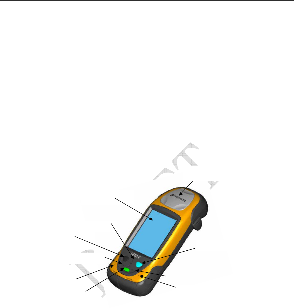
GRS Front
The front of the GRSis the primary interface with its components and installed software.
• The internal GPS antenna detects signals from GPS+ satellites and sends them to the GPS receiver board for
processing.
5
• The display screen and touch panel provides a graphical and tactile user interface for the unit.
• The power button turns the receiver on and off.
• The ESC (escape) button exits from the current screen or function.
• The ENT (enter) button applies settings, numerical values, and records points (depending on the settings of
internal software). Pressing this button for one second activates the controller’s Windows Start menu.
• The Bluetooth/Wireless LAN LED indicates the level of activity at the Bluetooth wireless technology module:
– Solid blue light: the Bluetooth module is on and a connection has been established.
– Blink red light:the Wireless LAN is on
– Red, blue led blinks alternately Bluetooth and Wireless LAN are ON
– No light: the both modules are off.
• The charging LED indicates the level of charge in the battery:
– Green: battery has a full charge.
– Red: battery is charging.
– Red blink: charging error.
Figure 1-3. GRS Front
Internal GPS
Antenna Cover
Display and Touch
screen
Escape Button
Enter Button
Power Button
Charging LED
Speaker
MicroPhone
Cell Phone Modem LED
Bluetooth /Wireless LAN LED
Introduction
GRS Operator’s Manual
6
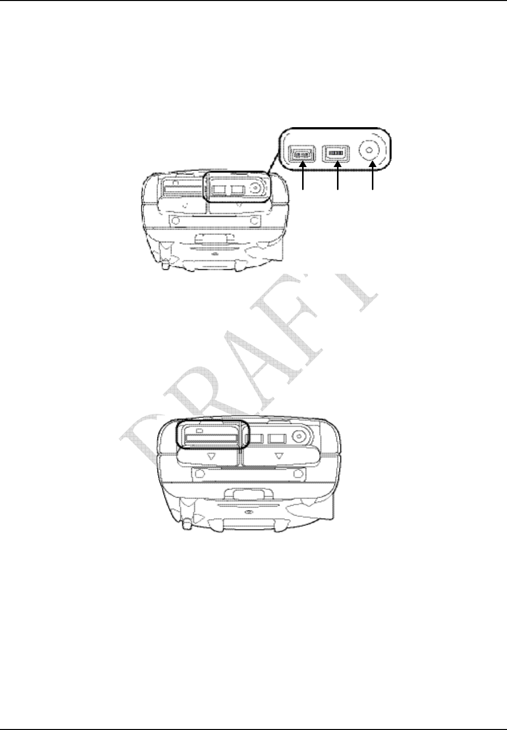
USB Serial
(port A) Power
GRS Ports
The GRS has the following three ports:
• USB – used for high-speed connection to a computer via ActiveSync.
• Serial – used for communication between the internal GPS module (port A of the module) and an external
device.Power – used to connect the GRS to an external power source. This port can also be used to charge the
batteries.
Figure 1-5. GRS Ports
SD Card Slot
The SD (secure digital) slot provides extended memory for the controller (SD Card Slot). The data that resides on
the SD card can be accessed via the USB or serial port, or Bluetooth wireless technology. A secure digital card can
be purchased at your local computer supply store. Located above the card slot is the software reset button for
restarting the operating system if software is not responding.
Figure 1-6. SD Card Slot
SD Card Slot
So
f
tware Reset
Button
7
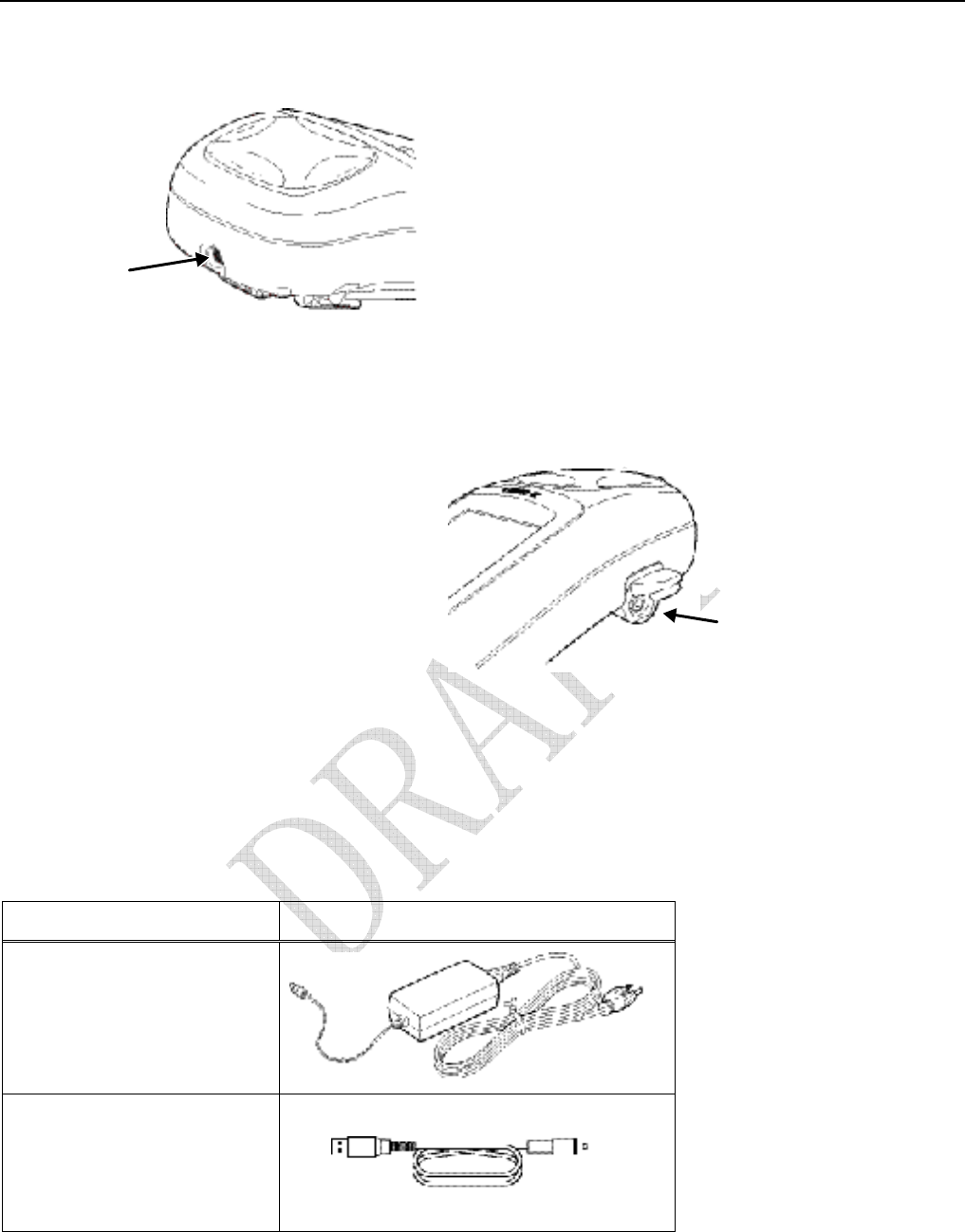
Integrated Camera
The integrated 1.3 megapixel camera can be used for taking pictures.
Camera
Figure 1-7. GRS Camera
External GPS Antenna Connector
The external GPS antenna connector allows an optional external antenna to be connected to the controller for
post-process survey applications.
External GPS
Antenna
Connector
Figure 1-8. GRS External GPS Antenna Connector
System Cables
The GRS package includes standard communication and power cables for communicating with the GRS and
providing a power source. GRS Package Cables lists the cables included in the standard GRS package.
Table 1-1. GRS Package Cables
Cable Description Cable Illustration
AC Power cable and adapter
Connects the GRS to a grounded
outlet.
USB cable
Connects the GRS to an external
device (controller or computer) for
high-speed data transfer and receiver
configuration.
Introduction
GRS Operator’s Manual
8
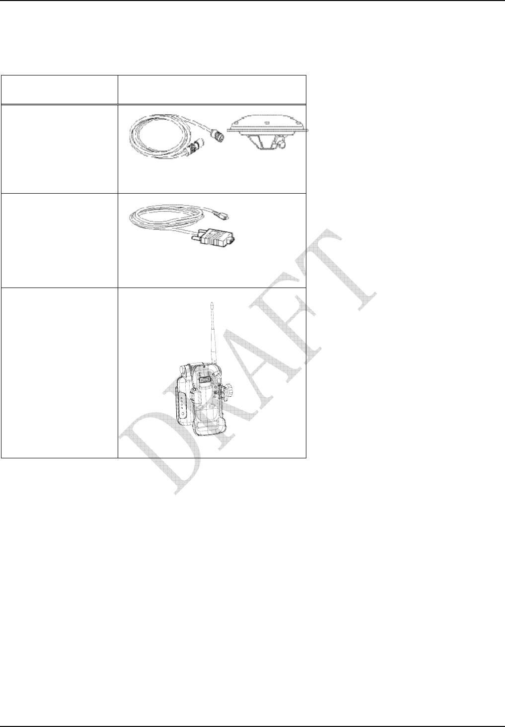
Optional Accessories
Table 1-2. GRS Op gives a brief list of optional accessories that can be used
with the GRS. Contact your dealer to purchase optional accessories. GRS
Optional Accessories
Accessory Illustration
External GPS Antenna and
Cable
Connecting an external
PG-A1 GPS antenna increases
the range of the GRS.
Serial cable
Connects the GRS to an
external device (controller or
computer) for data transfer and
receiver configuration.
NOTE:A ferrite core is
attached to this cable.
Radio Modem Holder