Topcon America 80501WL GNSS RECEIVER SYSTEM User Manual GRS SPEC 081021
Topcon America Corporation GNSS RECEIVER SYSTEM GRS SPEC 081021
Contents
- 1. Users Manual 1
- 2. Users Manual 2
- 3. Users Manual 3
Users Manual 2

DRAFT
Appendix B
P/N 7010-0752
1
Specifications
This TPS product is a 50-channel GPS receiver integrated with an internal computer and Windows
Mobile6.0 operating system with touch screen, a digital camera, a Bluetooth® wireless technology
module, celler module(option),an electronic compass, and an SD card slot. The portable design and
product integration allows this device to be a fully-functional, productive tool at any job.
Performance specifications assume a minimum of 6
GPS satellites above 15 degrees in elevation and
adherence to the procedures recommended in this
manual.
In areas of high multipath, during periods of large
PDOP, and during periods of increased ionospheric
activity, performance may degrade.
Use robust checking procedures in areas of extreme
multipath or under dense foliage.

Specifications
GRS Operator’s Manual
2
GRS Specifications
The following sections provide specifications for the GRS and its internal components.
General Details
GRS General Specifications table lists the receiver’s general specifications.
Table B-1. GRS General Specifications
Physical
Enclosure ABS
Color Topcon Yellow
and Topcon Grey
Dimensions D: 213 x W: 93 x H: 46mm
Weight 0.77 kg
Antenna Internal
Battery Internal, rechargeable/replaceable
Backup, replaceable
Controller Integrated; uses Windows Mobile 6.0 operating system
Keys (buttons) Three keys:
Power – On/Off
ENT – applies settings, numerical values, and records points; shows
Windows Start menu
ESC – exits from the current screen or function
LEDs Three LEDs:
Bluetooth – indicates Bluetooth wireless technology connection status
Power – indicates charge level
Cell Phone modem-connection status
Environment
Operating
temperature
-20 C° to +50 C° with batteries
-10 C° to +50 C° using camera
Storage
temperature
-30 C° to +60 C° with batteries
Waterproof IP66 at closing all connector caps.
Power
Internal battery Li-ion, 2500 mAh, 7.4 V
; repeatable
P/N 7010-0752
3
Operating time
(Back light OFF,
L1 GPS mode)
No less than 3.5 hours with GPS and cell phone use.
No less than 5 hours with GPS use.
No less than 8 hours without GPS and cell phone.
Supply from Holder (without Radio modem operates)
No less than 10 hours with GPS and cell phone use.
External power 1 port
Contact Pin: From the battery Holder.
Input voltage 12 V DC (for charge battery)
Consumption 5.3W while in simultaneous use of WM, GPS and GSM
Battery charger Connect the AC adaptor to charge the power port.
Available run charge when connected to a portable external power source.
Charging time 5 hours for full charge. (Use standard accessory AC/DC adaptor)
On-board Backup battery for timekeeping; replaceable button-type battery; 8–10 years
normal operation
Connectors and Slot
Serial port 1 port for communication with the GMS+ board (port A); small connector
USB port 1 port for Windows CE; type B mini ver 1.1; connect to PC using
ActiveSync
External power port 1 port; DC Jack type A; for connecting the AC adaptor or external battery
External antenna
connector Lemo FLS.00.250 connector
3VDC output to external antenna
SD card slot 1 slot for memory storage and I/O
Contact Pins
(To Holder and
Cable)
These are contact 12 pins on the back of GRS.
TX, RX, RTS, CTS (GPS port-D), PPS, EVENT, LoBAT,
HolderDetc, GMSXDetec, PW, GND, Spare
GPS board Port-D: 232C level
Bound rate: 460800, 230400, 115200(Default), 57600,
38400, 19200, 9600, 4800, 2400, 1200, 600, 300
Length: 7,8(Default)
Stop bit: 1(Default), 2
Parity: None (Default), Odd, Even
Power Pin (For only Radio/Battery holder.)
Specifications
GRS Operator’s Manual
4
Communication
Serial port Port A of GPS+ board
Baud rate = 460800, 230400, 115200, 2400, 1200, 600, 300
Flow control = RTC/CTS
Length= 7, 8 (default)
Stop bit= 1 (default, 2
Parity= None (default), Odd, Even
Bluetooth Version: Bluetooth standard 1.2; Class 2; Profile: SPP, DUP
Multiple connection capability (4 ports)
Wireless LAN 802.11b/g
USB Version 1.1
Windows Mobile6.0
Processor Intel PXA320
Processor speed 806MHz
Operating System Microsoft Windows Mobile 6.0
Digital Camera
Pixel 2.0M (UXGA...1600x1200)
Sensor element 1/4 inches color C-MOS sensor
Compass
Type Magnet resistive sensor
Accuracy ±10 divisions
LCD Display
Size 640x480 VGA (portrait) 3.7 inch color TFT transmissive type
Backlight LED
Touch screen Resistive touch screen; passive
Audio
P/N 7010-0752
5
Speaker Mono
Microphone Mono
Memory
Internal memory DDR2 SDRAM 256MB
External memory Via SD card slot
GPS Details
GPS Board Specifications lists the GPS board’s general specifications.
Table B-2. GPS Board Specifications
Tracking Specifications
Tracked Signals GPS/GLONASS L1/L2 C/A Code & Carrier, GPS L2C
SBAS (WAAS/EGNOS/MSAS)
Receiver Type G - GPS L1
GD – GPS L1/L2
GGD - GPS/GLONASS L1/L2
Standard Channels 72 channels
Cold Start
Warm Start
Reacquisition
< 30 sec
< 10 sec
< 1 sec
Survey Accuracy
Static L1 (1Sigma)
H: 3mm + 0.8ppm (x baseline length)
V: 4mm + 1.0ppm (x baseline length)
L1+L2:
H: 3mm + 0.5ppm (x baseline length)
V: 5mm + 0.5ppm (x baseline length)
PP Kinematic L1: (1Sigma)
H: 10mm + 1ppm (x baseline length)
V: 15mm + 1ppm (x baseline length)
DGPS Real time/Post processing: 0.5m (1Sigma)
RTK (1Sigma)
H: 10mm + 1ppm
V: 15mm + 1ppm
Specifications
GRS Operator’s Manual
6
Other (GPS)
Real time data
format
RTCM 2.3, 3.0; CMR, CMR+; TPS
NMEA NMEA 2.2, 2.3, 3.0
Output rate Up to 10Hz
Connector Specifications
The GRS has one antenna connector for radio transmission/reception and three port connectors for
power and data upload/download.
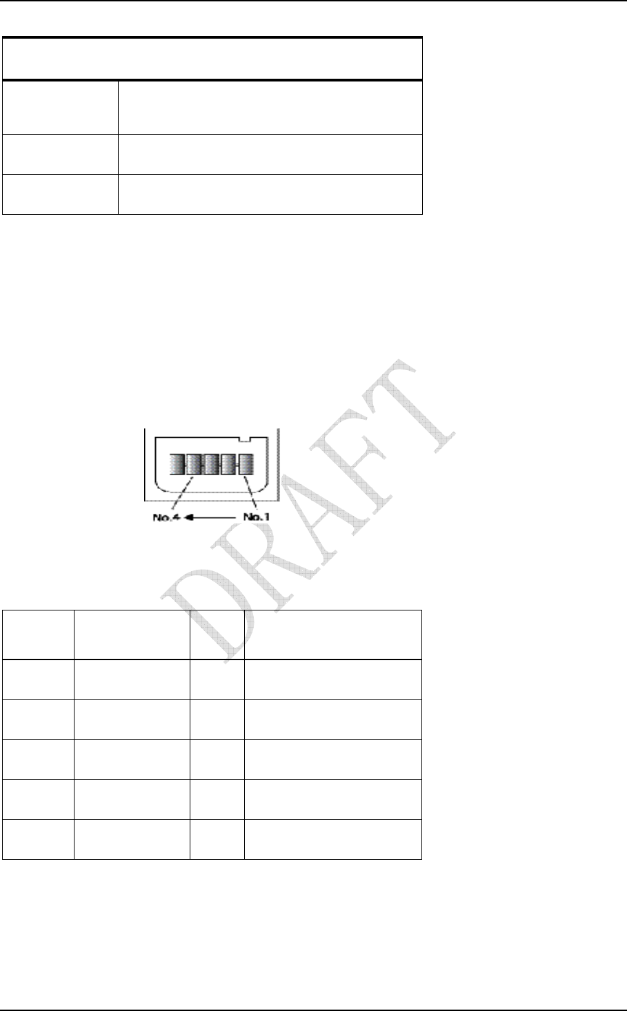
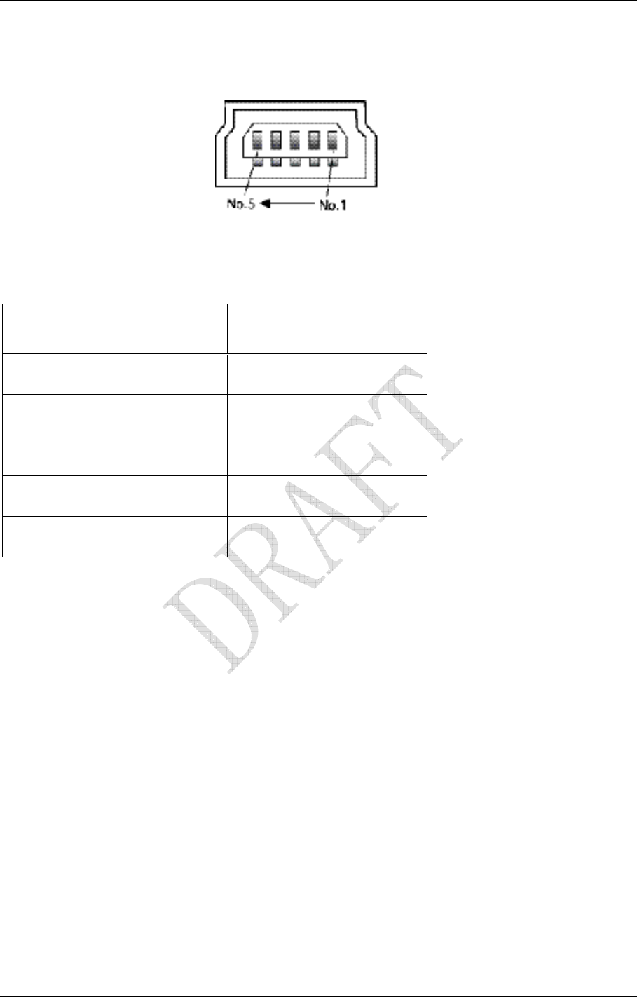
Serial Connector
The serial connector (Serial RS23) is a sealed receptacle, 5 pin, port. This connector is configured as
port A of the internal GPS receiver.
Figure B-1. Serial RS232 Connector
Serial Pin Specifications gives the serial port’s pin specifications.
Table B-3. Serial Pin Specifications
Number Signal Name Dir Details
1 TXD O Clear to send
2 RXD I Request to send
3 GND - Signal ground
4 GND - Signal ground
5 Not used
P/N 7010-0752
7
USB Connector
Rimmed in yellow, the USB connector is a sealed receptacle, 4 pin TPS cable connector (USB
Connector ).
Figure B-2. USB Connector for GGD Options
USB Specifications gives the USB connector specifications.
Table B-4. USB Specifications
Number Signal Name Dir Details
1 VDD P Bus power input
2 V- I/O Data minus
3 V+ I/O Data plus
4 Not used
GND - Ground