Topcon America 841221 Spread Spectrum Transmitter User Manual UsersManual GMS 2Pro
Topcon America Corporation Spread Spectrum Transmitter UsersManual GMS 2Pro
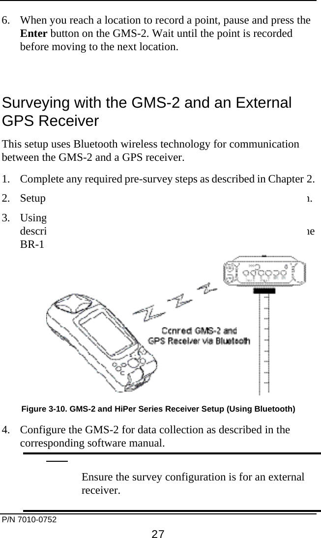
UserManual.wiki
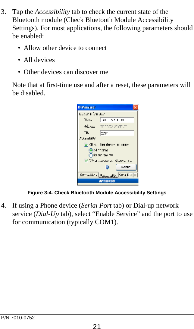
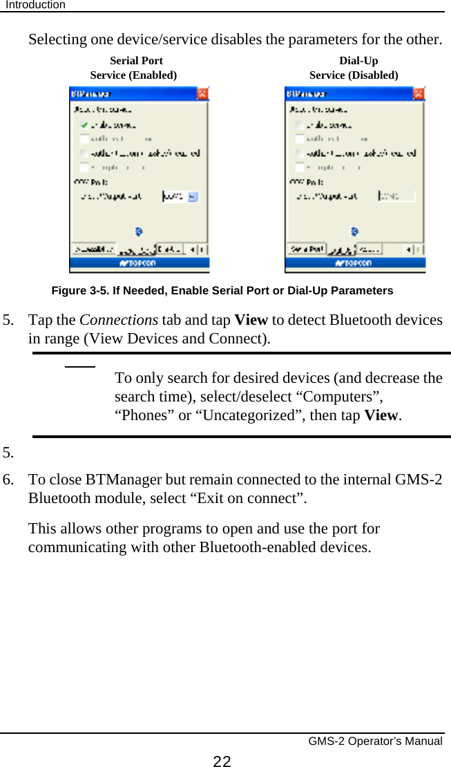
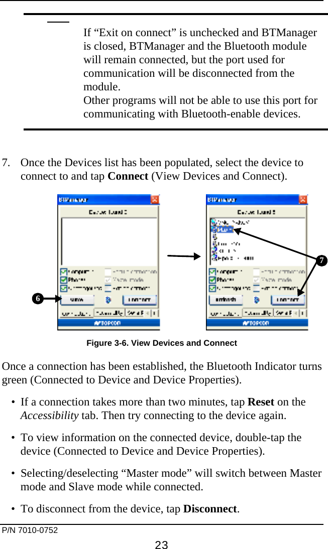
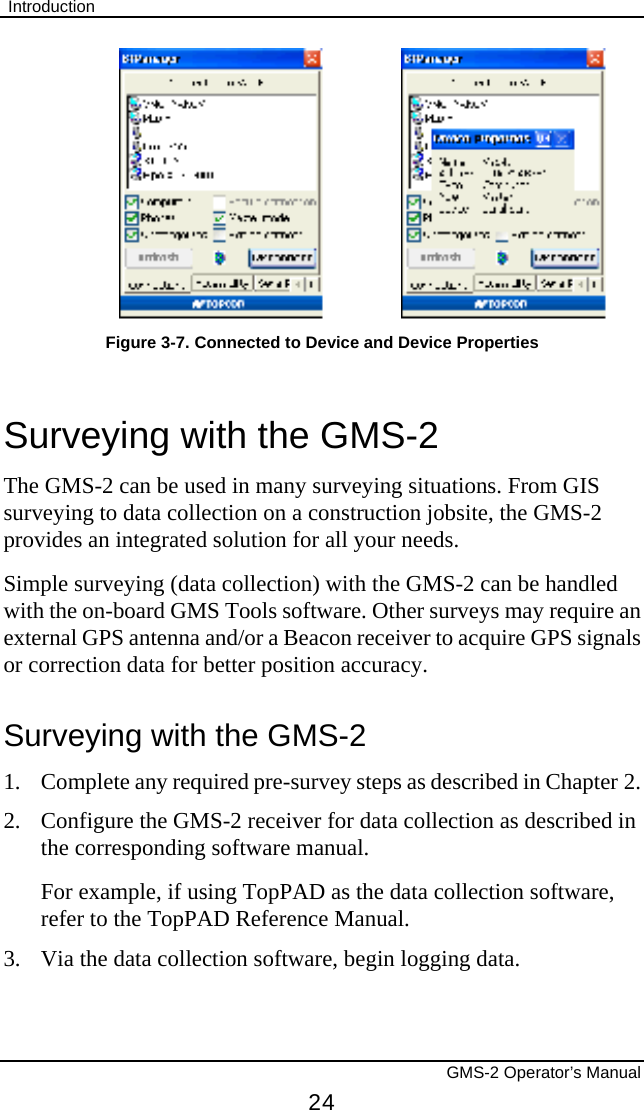
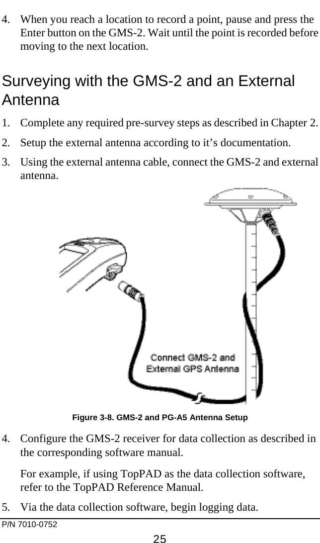
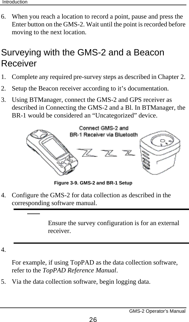
>
Topcon America
>
841221 User Manual
User Manual
Navigation menu
Upload a User Manual
Namespaces
Wiki Guide
HTML
PDF
Info
Views
User Manual
Discussion / Help
Navigation