Topcon America 841221 Spread Spectrum Transmitter User Manual UsersManual GMS 2Pro
Topcon America Corporation Spread Spectrum Transmitter UsersManual GMS 2Pro
User Manual

DRAFAFT
P/N 7010-0752
1
Introduction
The GMS-2Pro receiver is a single-frequency, GPS+GLONASS L1
receiver and hand-held controller built to be the most advanced,
compact, and portable receiver for the GIS surveying market. An
integrated electronic compass and digital camera make the GMS-2Pro
an all-purpose, GIS field mapping unit.
The GMS-2Pro receiver is a multi-function, multi-purpose receiver
intended for precision markets. Precision markets means markets for
equipment, subsystems, components and software for surveying,
construction, commercial mapping, civil engineering, precision
agriculture and land-based construction and agriculture machine
control, photogrammetry mapping, hydrographic and any use
reasonably related to the foregoing.
The GMS-2Pro provides the functionality, accuracy, availability, and
integrity needed for fast and easy data collection.
Principles of Operation
Surveying with the right GPS receiver can provide users accurate and
precise positioning, a requirement for any surveying project.
This section gives an overview of existing and proposed Global
Navigation Satellite Systems (GNSS) and receiver functions to help
you understand and apply basic operating principles, allowing you to
get the most out of your receiver.
GNSS Overview
Currently, the following three global navigation satellite systems
(GNSS) offer line-of-site radio navigation and positioning, velocity,

Introduction
GMS-2 Operator’s Manual
2
and time services on a global, all-weather, 24-hour scale to any user
equipped with a GNSS tracking receiver on or near the Earth’s
surface:
• GPS – the Global Positioning System maintained and operated by
the United States Department of Defense. For information on the
status of this system, visit the US Naval Observatory website
(http://tycho.usno.navy.mil/) or the US Coast Guard website
(http://www.navcen.uscg.gov/).
• GLONASS – the Global Navigation Satellite System maintained
and operated by the Russian Federation Ministry of Defense. For
information on the status of this system, visit the Ministry of
Defense website (http://www.glonass-center.ru/frame_e.html).
• GALILEO – an upcoming global positioning system maintained
and operated by Galileo Industries, a joint venture of several
European space agencies working closely with the European
Space Agency. Unlike GPS and GLONASS, this is a civil
endeavor and is currently in the development and validation stage.
For information on the status of this system, visit the Galileo
Industries website (http://www.galileo-industries.net).
Despite numerous technical differences in the implementation of
these systems, satellite positioning systems have three essential
components:
• Space – GPS, GLONASS, and GALILEO satellites orbit
approximately 12,000 nautical miles above Earth and are
equipped with a clock and radio. These satellites broadcast digital
information (ephemerides, almanacs, time&frequency corrections,
etc.).
• Control – Ground stations located around the Earth that monitor
the satellites and upload data, including clock corrections and new

P/N 7010-0752
3
ephemerides (satellite positions as a function of time), to ensure
the satellites transmit data properly.
• User – The community and military that use GNSS receivers and
the corresponding satellites to calculate positions.
Calculating Absolute Positions
When calculating an absolute position, a stationary or moving
receiver determines its three-dimensional position with respect to the
origin of an Earth-Center Earth-Fixed coordinate system. To calculate
this position, the receiver measures the distance (called
pseudo-ranges) between it and at least four satellites. The measured
pseudo-ranges are corrected for clock differences (receiver and
satellites) and signal propagation delays due to atmospheric effects.
The positions of the satellites are computed from the ephemeris data
transmitted to the receiver in navigation messages. When using a
single satellite system, the minimum number of satellites needed to
compute a position is four. In a mixed satellite scenario (GPS,
GLONASS, GALILEO), the receiver must lock onto at least five
satellites to obtain an absolute position.
To provide fault tolerance using only GPS or only GLONASS, the
receiver must lock onto a fifth satellite. Six satellites will provide fault
tolerance in mixed scenarios.
Calculating Differential Positions
DGPS, or Differential GPS, typically uses the measurements from two
or more remote receivers to calculate the difference (corrections)
between measurements, thus providing more accurate position
solutions.
With DGPS, one receiver is placed at a known, surveyed location and
is referred to as the reference receiver or base station. Another
receiver is placed at an unknown, location and is referred to as the
remote receiver or rover. The reference station collects the range

Introduction
GMS-2 Operator’s Manual
4
measurements from each GPS satellite in view and forms the
differences (corrections) between the calculated distance to the
satellites and the measured pseudo-ranges to the satellites.
These corrections are then built up to the industry standard (RTCM or
various proprietary standards) established for transmitting differential
corrections and broadcast to the remote receiver(s) using a data
communication link. The remote receiver applies the transmitted
DGPS corrections to its range measurements of the same satellites.
Using this technique, the spatially correlated errors—such as satellite
orbital errors, ionospheric errors, and tropospheric errors—can be
significantly reduced, thus improving the position solution accuracy
of the GPS.
A number of differential positioning implementations exist, including
post-processing surveying, real-time kinematic surveying, maritime
radio beacons, geostationary satellites (as with the OmniSTAR
service), and the wide area augmentation system (WAAS) service.
The real-time kinematic (RTK) method is the most precise method of
real-time surveying. RTK requires at least two receivers collecting
navigation data and communication data link between the receivers.
One of the receivers is usually at a known location (Base) and the
other is at an unknown location (Rover). The Base receiver collects
carrier phase measurements, generates RTK corrections, and sends
this data to the Rover receiver. The Rover processes this transmitted
data with its own carrier phase observations to compute its relative
position with high accuracy, achieving an RTK accuracy of up to 1 cm
horizontal and 1.5 cm vertical.
Essential Components for Quality Surveying
Achieving quality position results requires the following elements:
• Accuracy – The accuracy of a position primarily depends upon the
satellite geometry (Geometric Dilution of Precision, or GDOP)
and the measurement (ranging) errors.

P/N 7010-0752
5
– Differential positioning (DGPS and RTK) strongly mitigates
atmospheric and orbital errors, and counteracts Selective
Availability (SA) signals the US Department of Defense
transmits with GPS signals.
– The more satellites in view, the stronger the signal, the lower
the DOP number, the higher positioning accuracy.
• Availability – The availability of satellites affects the calculation
of valid positions. The more visible satellites available, the more
valid and accurate the position. Natural and man-made objects can
block, interrupt, and distort signals, lowering the number of
available satellites and adversely affecting signal reception.
• Integrity – Fault tolerance allows a position to have greater
integrity, increasing accuracy. Several factors combine to provide
fault tolerance, including:
– Receiver Autonomous Integrity Monitoring (RAIM) detects
faulty GPS and GLONASS satellites and removes them from
the position calculation.
– Five or more visible satellites for only GPS or only
GLONASS; six or more satellites for mixed scenarios.
– Wide Area Augmentation Systems (WAAS, EGNOS, etc.)
creates and transmit, along with DGPS corrections, data
integrity information (for example, satellite health warnings).
– Current ephemerides and almanacs.
Conclusion
This overview simply outlines the basics of satellite positioning. For
more detailed information, visit the TPS website.
GMS-2Pro Overview
The GMS-2 is a fully integrated hand-held controller and GPS+
receiver. Included in the system is an electronic compass and digital
camera.

Introduction
GMS-2 Operator’s Manual
6
The hand-held controller component of the GMS-2Pro
includes the Windows® CE operating system and color LCD touch
screen. Integrated Bluetooth® wireless technology allows this system
to be a cable-free controller/receiver for maximum portability. The
rugged casing is durable and built for rugged use.
As a field controller, the GMS-2Pro can run a full suite of field
software for working with total stations and RTK GPS systems.
The GPS+ receiver component of the GMS-2
can receive and process GPS+GLONASS L1 signals improving the
accuracy of your survey points and positions. The GPS+ features of
the receiver combine to provide a positioning system accurate for any
survey. Several other features, including multipath mitigation, provide
under-canopy and low signal strength reception.
When power is turned on and the receiver self-test completes, the
receiver’s 50 channels initialize and begin tracking visible satellites.
Each of the receiver’s channels can be used to track any one of the
GPS or GLONASS signals. The number of channels available allows
the receiver to track all visible GPS satellites at any time and location.
An internal GPS antenna equipped with a low noise amplifier (LNA)
and the receiver’s radio frequency (RF) device are connected with a
coaxial cable. The wide-band signal received is down-converted,
filtered, digitized, and assigned to different channels. The receiver
processor controls the process of signal tracking.
Once the signal is locked in the channel, it is demodulated and
necessary signal parameters (carrier and code phases) are measured.
Also, broadcast navigation data are retrieved from the navigation
frame.
After the receiver locks on to four or more satellites, it is possible to
solve the so-called “absolute positioning problem” and compute the
receiver’s coordinates (in WGS-84) and the time offset between the

P/N 7010-0752
7
receiver clock and GPS time. All this information can be stored in the
the optional SD card and internal flash memory, then processed using
a post-processing software package.
Capabilities of the GMS-2Pro receiver include:
• Multipath reduction
• Wide area augmentation system (WAAS)
• Single-frequency static, kinematic, and differential GPS (DGPS)
survey modes
• Setting different mask angles
• Setting different survey parameters
The integrated 1.3 megapixel camera
is used taking pictures of surveyed objects or survey sites.
Getting Acquainted with the GMS-2Pro
The GMS-2Pro is an integrated field controller and 50-channel GPS
receiver with an internal electronic compass and digital camera. USB
and serial ports, along with Bluetooth® wireless technology provide
communication paths with other devices. An external GPS antenna
connector allows an optional PG-A5 antenna to be connected for
centimeter-level surveys.
The standard GMS-2Pro package contains the following items:
• GMS-2Pro integrated receiver/controller activated for GPS L1
signals
• Handstrap and soft case
• USB cable and power converter/adapter cable
• BTManager and GMS Tools factory-installed software
Introduction
GMS-2 Operator’s Manual
8
For more details on accessories and options available for the GMS-2,
contact your local Topcon dealer.
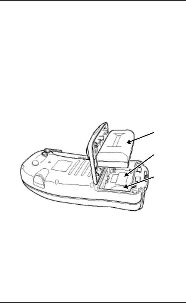
Rechargeable and Backup Batteries
The GMS-2 comes equipped with a rechargeable battery (GMS-2Pro
Battery) for powering the unit. The battery can be charged in the unit
or in an optional battery charger. A backup battery is also located in
the battery pocket and the unit’s serial number is located under the
battery.
The battery provides seven hours of operation, depending on the mode
of the receiver. Under normal conditions, the backup battery provides
eight to ten years of power backup for data and system integrity.
Backup
Battery
Battery
Serial
Number
Figure 1-2. GMS-2Pro Battery
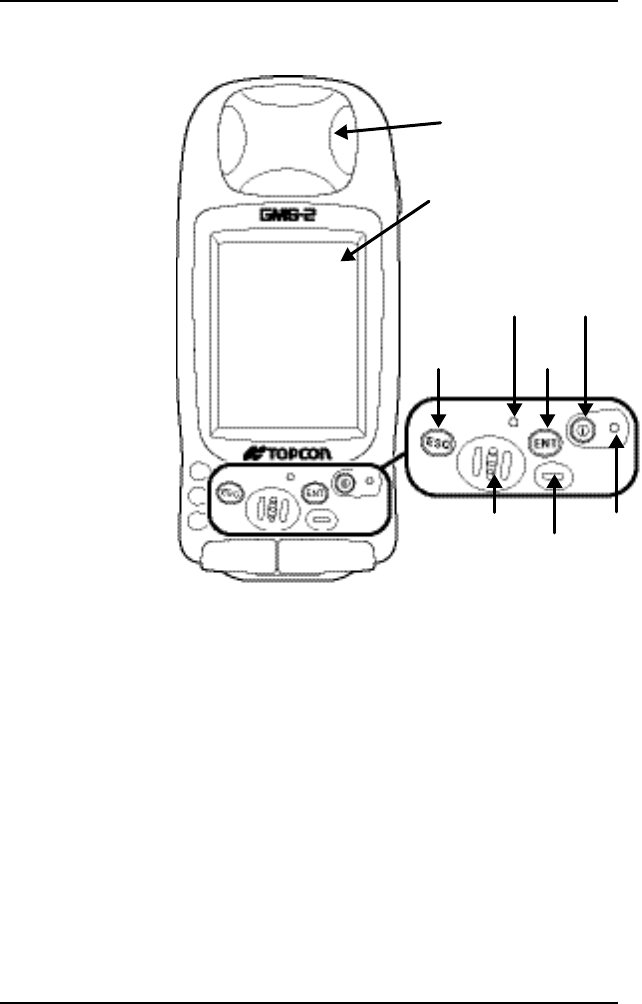
GMS-2Pro Front
The front of the GMS-2Prois the primary interface with its
components and installed software.
• The internal GPS antenna detects signals from GPS+ satellites
and sends them to the GPS receiver board for processing.

P/N 7010-0752
9
• The display screen and touch panel provides a graphical and
tactile user interface for the unit.
• The power button turns the receiver on and off.
• The ESC (escape) button exits from the current screen or
function.
• The ENT (enter) button applies settings, numerical values, and
records points (depending on the settings of internal software).
Pressing this button for one second activates the controller’s
Windows Start menu.
• The Bluetooth LED indicates the level of activity at the
Bluetooth wireless technology module:
– Solid blue light: the module is on and a connection has been
established.
– No light: the module is off.
• The charging LED indicates the level of charge in the battery:
– Green: battery has a full charge.
– Red: battery is charging.
Introduction
GMS-2 Operator’s Manual
10
– Red blink: charging error.
Escape
Button
SpeakerMicrophone
Charging LED
Enter
Button
Power
Button
Bluetooth
LED
Display and
Touch Screen
Internal GPS
Antenna Cover
Figure 1-3. GMS-2 Front
GMS-2Pro Back
The back of the GMS-2Pro holds the stylus used for tapping on the
display screen. An elastic strap provides comfortable security while
using the GMS-2Pro. A cover accesses the rechargeable battery and
P/N 7010-0752
11
backup battery.
Stylus Battery Cover
Hand
Strap
Hook
Hand
Strap
Hook
Battery
Cover
Latch
Figure 1-4. GMS-2 Back
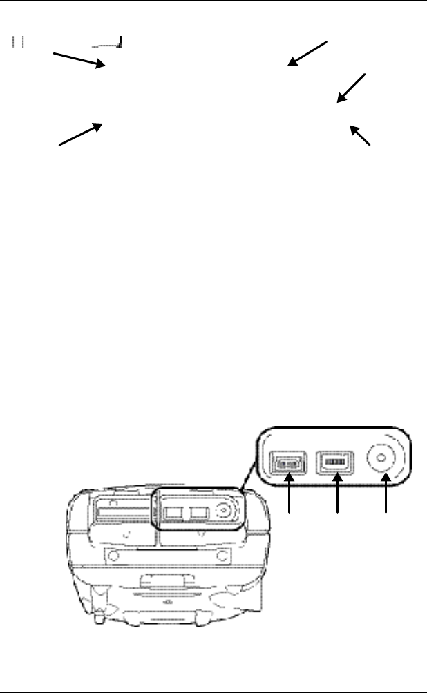
GMS-2Pro Ports
The GMS-2 has the following three ports:
• USB – used for high-speed connection to a computer via
ActiveSync.
• Serial – used for communication between the internal GPS
module (port A of the module) and an external device.
• Power – used to connect the GMS-2Pro to an external power
source. This port can also be used to charge the batteries.
USB Serial
(port A) Power
Figure 1-5. GMS-2 Ports
Introduction
GMS-2 Operator’s Manual
12
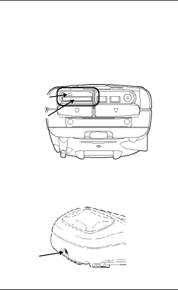
SD Card Slot
The SD (secure digital) slot provides extended memory for the
controller (SD Card Slot). The data that resides on the SD card can be
accessed via the USB or serial port, or Bluetooth wireless technology.
A secure digital card can be purchased at your local computer supply
store.
Located above the card slot is the software reset button for restarting
the operating system if software is not responding.
SD Card Slot
Sof tware Reset
Button
Figure 1-6. SD Card Slot
Integrated Camera
The integrated 1.3 megapixel camera can be used for taking pictures.
Camera
P/N 7010-0752
13
Figure 1-7. GMS-2 Camera
External GPS Antenna Connector
The external GPS antenna connector allows an optional external
antenna to be connected to the controller for post-process survey
applications.
External GPS
Antenna
Connector
Figure 1-8. GMS-2 External GPS Antenna Connector
System Cables
The GMS-2 package includes standard communication and power
cables for communicating with the GMS-2Pro and providing a power
source. GMS-2 Package Cables lists the cables included in the
standard GMS-2 package.
Table 1-1. GMS-2 Package Cables
Cable Description Cable Illustration
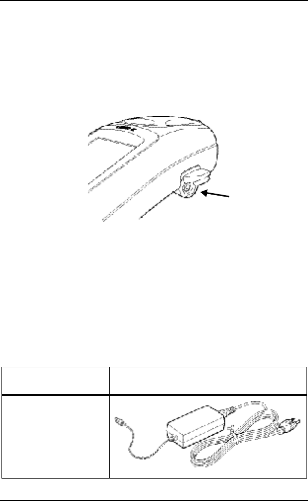
AC Power cable and
adapter
Connects the GMS-2Pro to
a grounded outlet.
Cable p/n 22-041002-01
Adapter p/n 14-008078-01
Introduction
GMS-2 Operator’s Manual
14
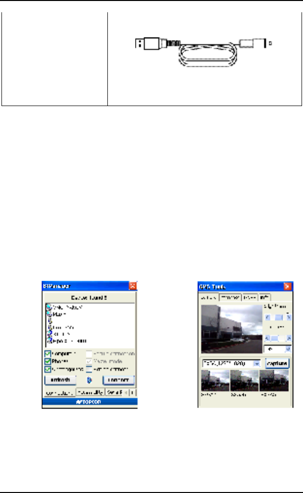
USB cable
Connects the GMS-2 to an
external device (controller
or computer) for high-speed
data transfer and receiver
configuration.
p/n 14-008081-01
GMS-2Pro Software
The GMS-2 comes with the following factory-installed software:
• BTManager – a utility that manages and controls the Bluetooth
module inside the GMS-2Pro. BTManager connects the
GMS-2Pro and other Bluetooth-enabled devices.
• GMS Tools – a utility that manages and controls the camera,
compass, and GNSS settings.
Figure 1-9. BT Manager and GMS Tools
P/N 7010-0752
15
Optional Accessories
GMS-2 Op gives a brief list of optional accessories that can be used
with the GMS-2Pro. Contact your dealer to purchase optional
accessories.
Table 1-2. GMS-2 Optional Accessories
Accessory Illustration
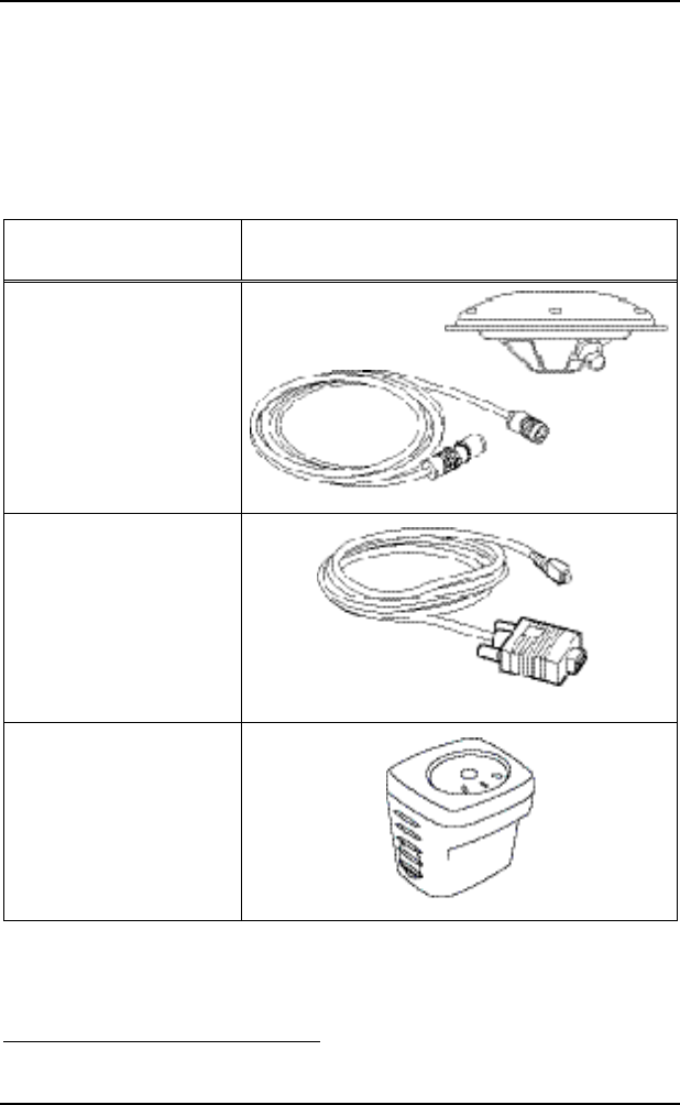
External GPS Antenna
and Cable
Connecting an external
PG-A5 GPS antenna
increases the range of the
GMS-2Pro.
PG-A5 p/n 01-844201-07
Cable p/n 14-008079-01
Serial cable
Connects the GMS-2Pro to
an external device
(controller or computer) for
data transfer and receiver
configuration.
p/n 14-008080-01
BR-11
The BR-1 is a receiver that
detect signals from local
Beacon stations. When
connected to the GMS-2Pro,
it provides correction data.
1As of the printing of this manual, the BR-1 is an upcoming Topcon
product.
Introduction
GMS-2 Operator’s Manual
16
Optional Software
TopSURV GIS and
TopPAD are GIS surveying
software that can enhance
and expand typical surveys
with GMS-2Pro.
TopP AD
TopSUR V GIS
For more details on other accessories and package options available
for the GMS-2Pro, contact your local Topcon dealer.
Option Authorization File (OAF)
Topcon Positioning Systems issues an Option Authorization File
(OAF) to enable the specific options that customers purchase. An
Option Authorization File allows customers to customize and
configure the receiver according to particular needs, thus only
purchasing those options needed.
Typically, all receivers ship with a temporary OAF that allows it to be
used for a predetermined period of time. When the receiver is
purchased, a new OAF permanently activates desired, purchased

P/N 7010-0752
17
options. Receiver options remain intact when clearing the NVRAM or
resetting the receiver.
The OAF enables the following functions. For a complete list of
available options and details, visit the TPS website or consult your
TPS dealer.
• Type of signal (standard GPS L1; optional GLONASS L1)
• Update rate 1Hz (standard) (optional 5 or 10Hz)
• RTCM Input/Output (standard)
• Advanced multipath reduction (standard)
• Wide Area Augmentation System (WAAS) (standard)
Introduction
GMS-2 Operator’s Manual
18
Using the GMS-2
The GMS-2 can be used as a stand-alone, L1 GPS+ receiver, or with
other devices. When installing software or performing file transfers,
the USB cable of Bluetooth module connects the GMS-2 to a
computer for in-office processing. For increased surveying accuracy,
a connected external GPS antenna or external receiver allows other
signals (such as L2 or Beacon) to be recorded.
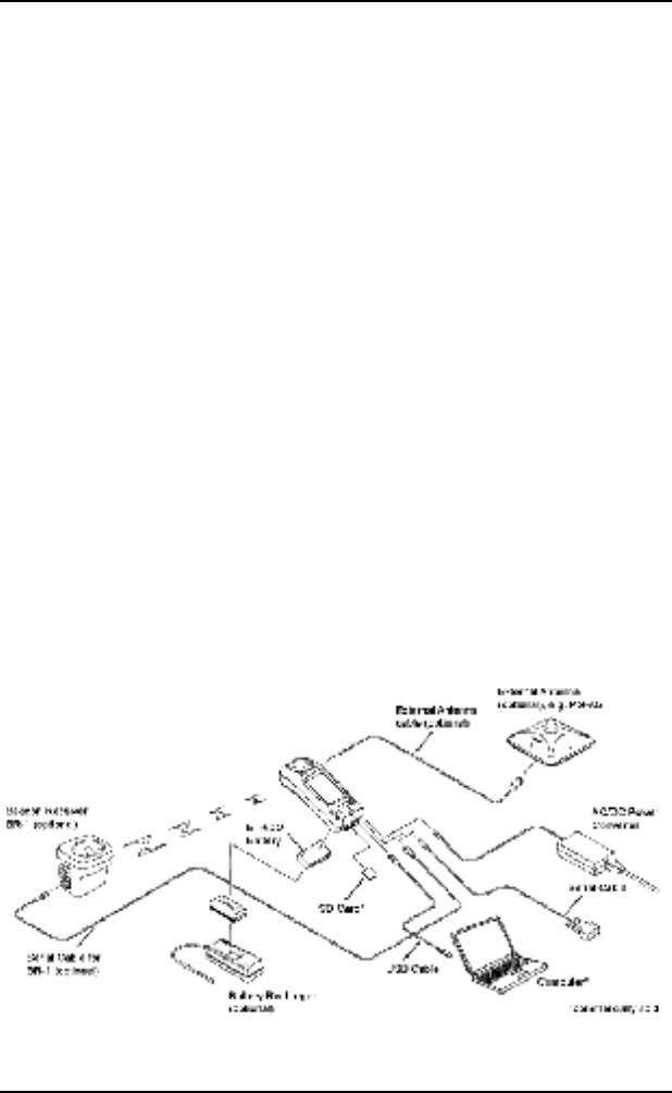
Connecting the GMS-2 with Other
Devices
The GMS-2 provides direct connection to devices with serial or USB
port, devices that support Bluetooth wireless technology, an external
GPS antenna (PG-A5), and receivers that provide correction
information. The various devices are optional and can be purchased
from your local Topcon dealer, or at a commercial retail store for
commercially sold products (such as the SD card).
P/N 7010-0752
19
Figure 3-1. GMS-2 System Connections
Connecting the GMS-2 and a Computer
Connecting the GMS-2 and a computer allows software to be installed
onto the controller and data to be uploaded from the controller to a
computer.
When connecting the GMS-2 and a computer, Microsoft ActiveSync
must be installed on the computer. See “Installing Microsoft
ActiveSync” on page 2-7 for details.
For a Bluetooth connection, see Connecting the
GMS-2 and a Bl for details.
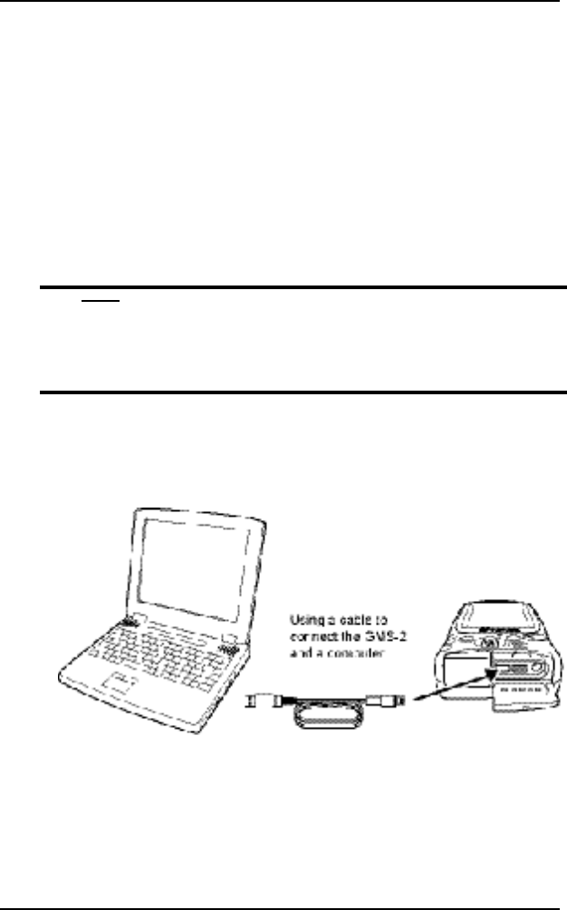
1. Connect the GMS-2 and the computer using the USB or serial
cable, or Bluetooth wireless technology.
Figure 3-2. Connect GMS-2 and Computer (USB) Using Cable
2. When ActiveSync on the computer prompts to set up a partnership,
select “No” and click Next.
Introduction
GMS-2 Operator’s Manual
20
3. Once the connection has been established, click the “Explorer”
icon on the ActiveSync screen to view data on the GMS-2
compact flash card.
Connecting the GMS-2 and a Bluetooth
Device
BTManager is a utility that connects the GMS-2 with available
Bluetooth devices for communication purposes. BTManager manages
and controls the Bluetooth module inside the GMS-2.
1. If needed, check the device to ensure Bluetooth communication is
supported.
2. On the GMS-2 control panel, double-tap the BTManager icon.
When BTManager starts, it immediately begins scanning GMS-2
ports to use for establishing a connection with the internal
Bluetooth module (the Bluetooth indicator will be red).
Once a connection has been established, the Bluetooth indicator
will turn white (BTManager Connected with GMS-2 Port).
Bluetooth
Indicator
Figure 3-3. BTManager Connected with GMS-2 Port
P/N 7010-0752
21
3. Tap the Accessibility tab to check the current state of the
Bluetooth module (Check Bluetooth Module Accessibility
Settings). For most applications, the following parameters should
be enabled:
• Allow other device to connect
• All devices
• Other devices can discover me
Note that at first-time use and after a reset, these parameters will
be disabled.
Figure 3-4. Check Bluetooth Module Accessibility Settings
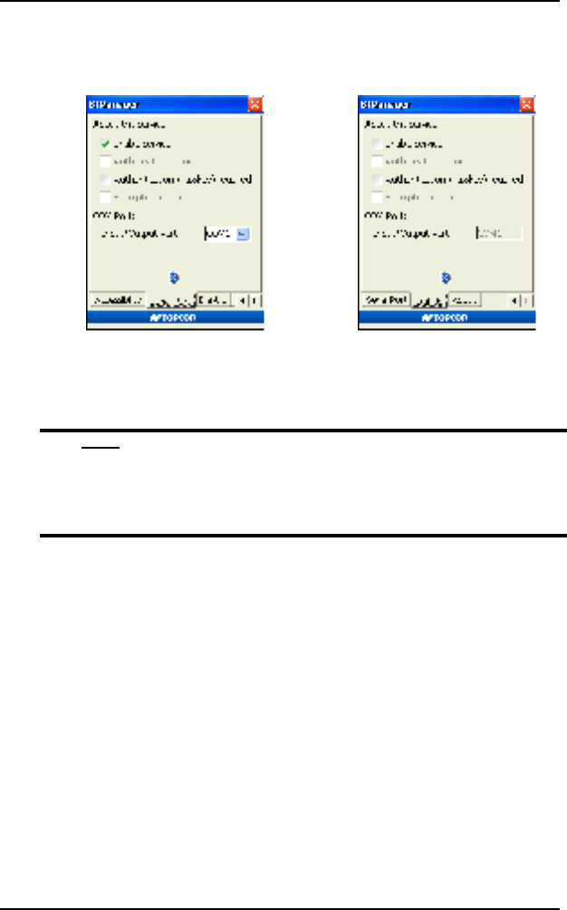
4. If using a Phone device (Serial Port tab) or Dial-up network
service (Dial-Up tab), select “Enable Service” and the port to use
for communication (typically COM1).
Introduction
GMS-2 Operator’s Manual
22
Selecting one device/service disables the parameters for the other.
Serial Port
Service (Enabled) Dial-Up
Service (Disabled)
Figure 3-5. If Needed, Enable Serial Port or Dial-Up Parameters
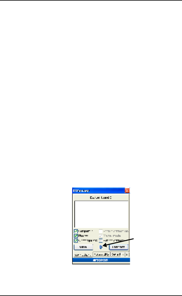
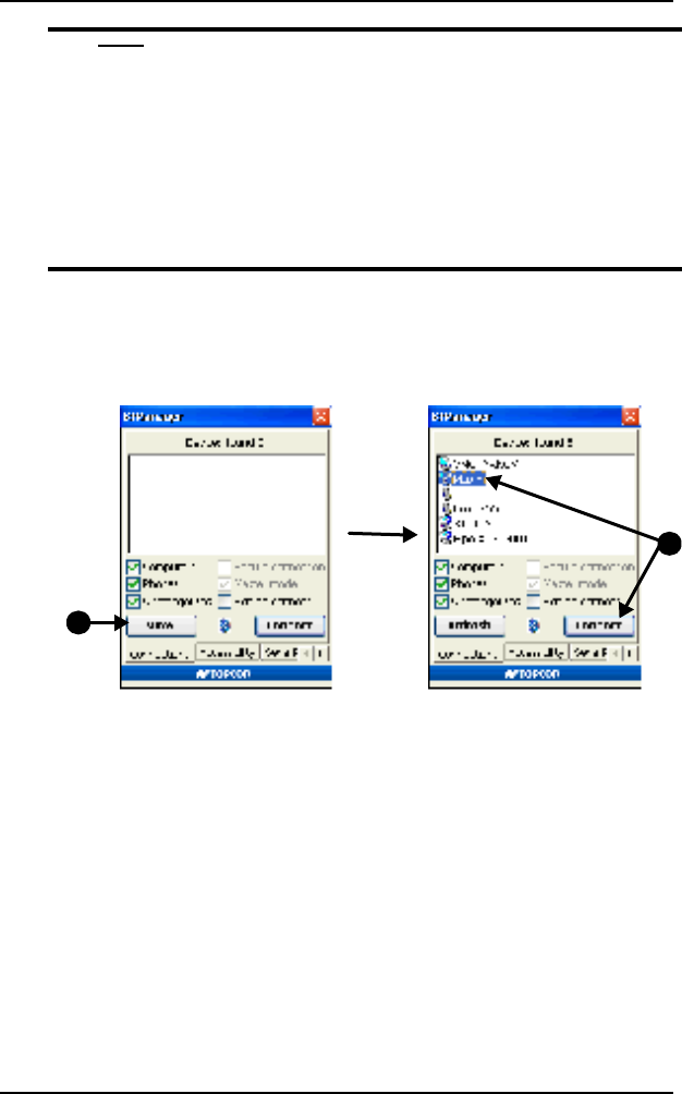
5. Tap the Connections tab and tap View to detect Bluetooth devices
in range (View Devices and Connect).
To only search for desired devices (and decrease the
search time), select/deselect “Computers”,
“Phones” or “Uncategorized”, then tap View.
5.
6. To close BTManager but remain connected to the internal GMS-2
Bluetooth module, select “Exit on connect”.
This allows other programs to open and use the port for
communicating with other Bluetooth-enabled devices.
P/N 7010-0752
23
If “Exit on connect” is unchecked and BTManager
is closed, BTManager and the Bluetooth module
will remain connected, but the port used for
communication will be disconnected from the
module.
Other programs will not be able to use this port for
communicating with Bluetooth-enable devices.
7. Once the Devices list has been populated, select the device to
connect to and tap Connect (View Devices and Connect).
6
7
Figure 3-6. View Devices and Connect
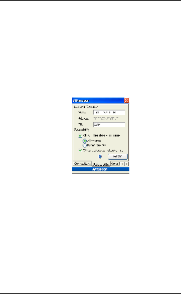
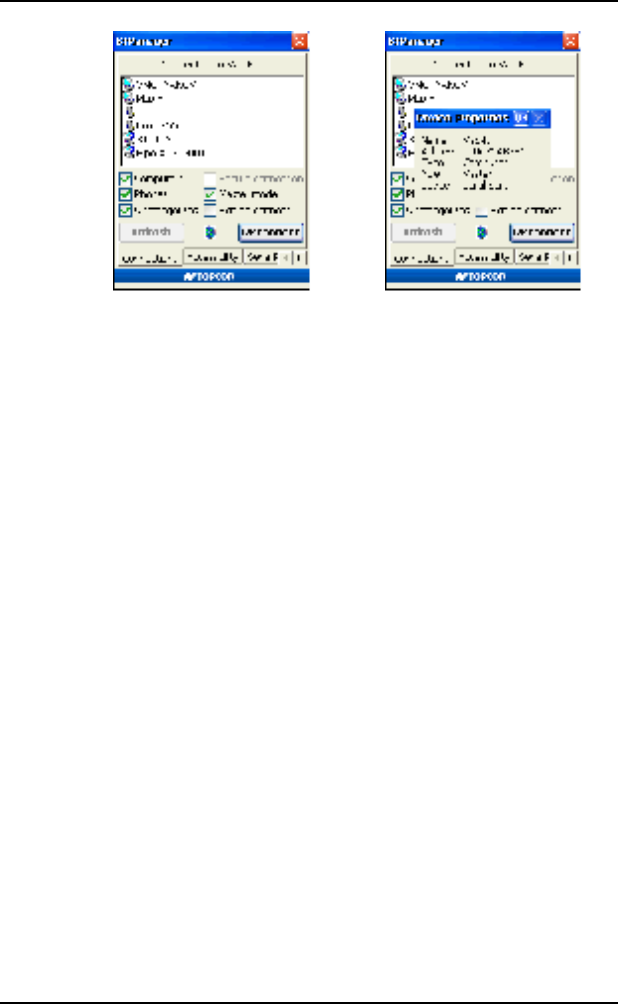
Once a connection has been established, the Bluetooth Indicator turns
green (Connected to Device and Device Properties).
• If a connection takes more than two minutes, tap Reset on the
Accessibility tab. Then try connecting to the device again.
• To view information on the connected device, double-tap the
device (Connected to Device and Device Properties).
• Selecting/deselecting “Master mode” will switch between Master
mode and Slave mode while connected.
• To disconnect from the device, tap Disconnect.
Introduction
GMS-2 Operator’s Manual
24
Figure 3-7. Connected to Device and Device Properties
Surveying with the GMS-2
The GMS-2 can be used in many surveying situations. From GIS
surveying to data collection on a construction jobsite, the GMS-2
provides an integrated solution for all your needs.
Simple surveying (data collection) with the GMS-2 can be handled
with the on-board GMS Tools software. Other surveys may require an
external GPS antenna and/or a Beacon receiver to acquire GPS signals
or correction data for better position accuracy.
Surveying with the GMS-2
1. Complete any required pre-survey steps as described in Chapter 2.
2. Configure the GMS-2 receiver for data collection as described in
the corresponding software manual.
For example, if using TopPAD as the data collection software,
refer to the TopPAD Reference Manual.
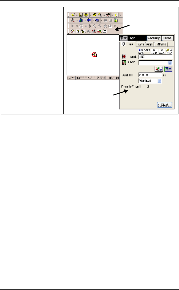
3. Via the data collection software, begin logging data.
P/N 7010-0752
25
4. When you reach a location to record a point, pause and press the
Enter button on the GMS-2. Wait until the point is recorded before
moving to the next location.
Surveying with the GMS-2 and an External
Antenna
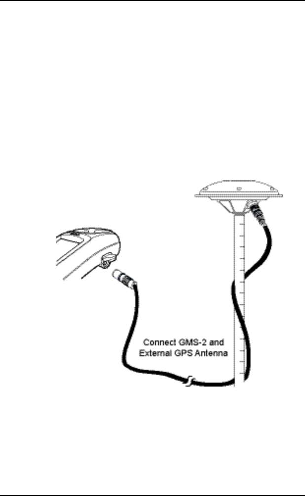
1. Complete any required pre-survey steps as described in Chapter 2.
2. Setup the external antenna according to it’s documentation.
3. Using the external antenna cable, connect the GMS-2 and external
antenna.
Figure 3-8. GMS-2 and PG-A5 Antenna Setup
4. Configure the GMS-2 receiver for data collection as described in
the corresponding software manual.
For example, if using TopPAD as the data collection software,
refer to the TopPAD Reference Manual.
5. Via the data collection software, begin logging data.
Introduction
GMS-2 Operator’s Manual
26
6. When you reach a location to record a point, pause and press the
Enter button on the GMS-2. Wait until the point is recorded before
moving to the next location.
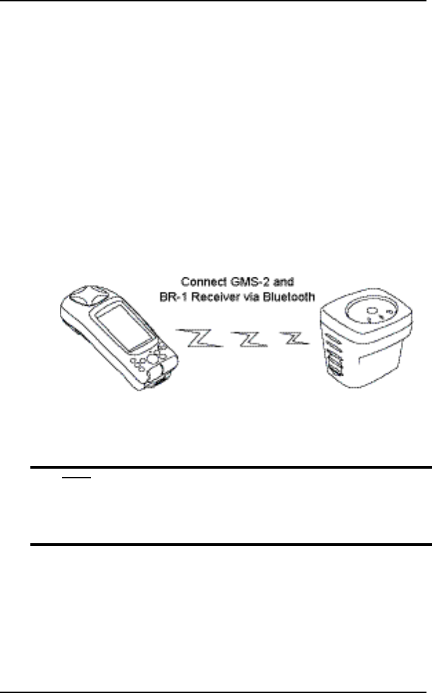
Surveying with the GMS-2 and a Beacon
Receiver
1. Complete any required pre-survey steps as described in Chapter 2.
2. Setup the Beacon receiver according to it’s documentation.
3. Using BTManager, connect the GMS-2 and GPS receiver as
described in Connecting the GMS-2 and a Bl. In BTManager, the
BR-1 would be considered an “Uncategorized” device.
Figure 3-9. GMS-2 and BR-1 Setup
4. Configure the GMS-2 for data collection as described in the
corresponding software manual.
Ensure the survey configuration is for an external
receiver.
4.
For example, if using TopPAD as the data collection software,
refer to the TopPAD Reference Manual.
5. Via the data collection software, begin logging data.
P/N 7010-0752
27
6. When you reach a location to record a point, pause and press the
Enter button on the GMS-2. Wait until the point is recorded
before moving to the next location.
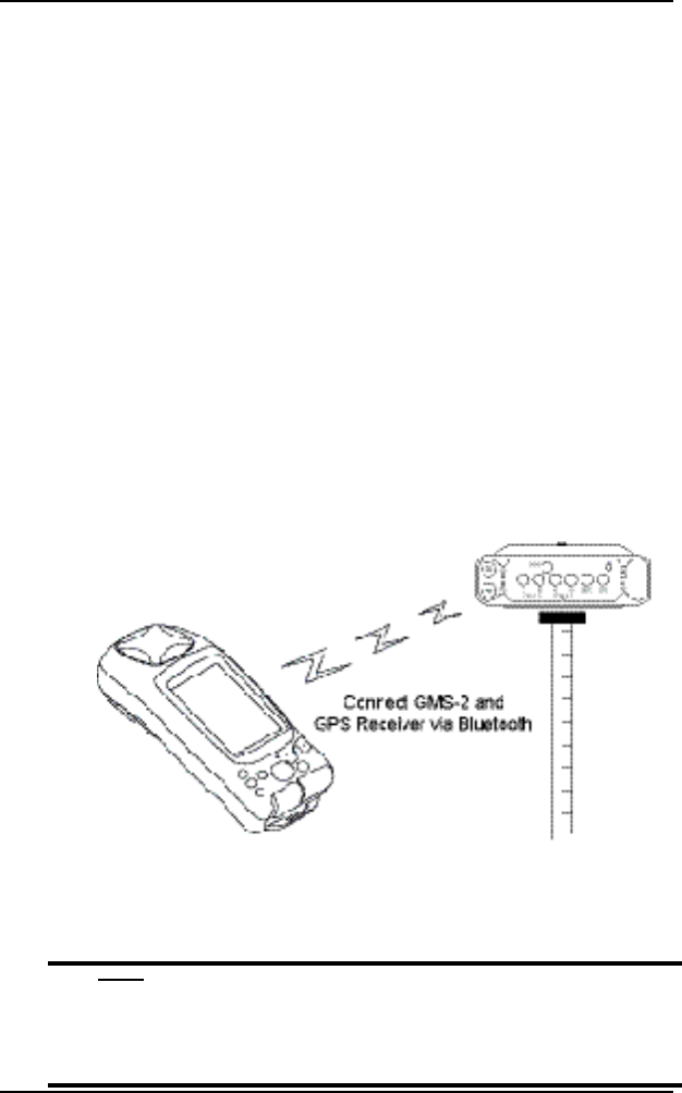
Surveying with the GMS-2 and an External
GPS Receiver
This setup uses Bluetooth wireless technology for communication
between the GMS-2 and a GPS receiver.
1. Complete any required pre-survey steps as described in Chapter 2.
2. Setup the external GPS receiver according to it’s documentation.
3. Using BTManager, connect the GMS-2 and GPS receiver as
described in Connecting the GMS-2 and a Bl. In BTManager, the
BR-1 would be considered an “Uncategorized” device.
Figure 3-10. GMS-2 and HiPer Series Receiver Setup (Using Bluetooth)
4. Configure the GMS-2 for data collection as described in the
corresponding software manual.
Ensure the survey configuration is for an external
receiver.

Introduction
GMS-2 Operator’s Manual
28
4.
For example, if using TopSURV as the data collection software,
refer to the TopSURV Reference Manual.
5. Via the data collection software, begin logging data.
6. When you reach a location to record a point, pause and press the
Enter button on the GMS-2. Wait until the point is recorded
before moving to the next location.
Backing up Windows CE RAM Data
The Windows CE RAM data stores such items as collected/saved data,
registry information, and installed programs. Performing a regular
backup of this data will ensure efficient and continued use of the
GMS-2. RAM data will be lost in the following situations:
• Losing battery power through draining the battery or removing
the battery.
The Windows CE RAM has a separate backup,
rechargeable battery. This battery will power the
RAM for five minutes after removing the primary
battery.
•
• Performing a hardware reset.
• Upgrading the operating system.
When backing up RAM data, data is stored on the internal flash
memory in a “Backup” directory.
1. On the main screen of the GMS-2, tap StartControl
PanelSystemBackup.

P/N 7010-0752
29
2. On the RAM Backup screen, tap RAM data backup. The backup
to the Flash memory will begin.
• If desired, turn on “Ram data will be backed up...” to
automatically back up RAM data as the GMS-2 shuts down.
• Leave “Data restoration after hard reset” on to recover data
after a hardware reset. Data will be restored after a hard reset
and power cycle.
If desired, turn it off (data will not be restored).
3. When the backup completes, tap OK.
Note the following conditions of a backup and restoration cycle:
• If the Flash memory does not have enough space to store a RAM
backup, the backup will be incomplete.
• After upgrading the OS, some items may not be fully restored.

Introduction
GMS-2 Operator’s Manual
30
Regulatory
Information
The following sections provide information on this product’s
compliance with government regulations for use.
FCC Compliance
This device complies with Part 15 of the FCC rules. Operation is
subject to the following two conditions:
(1) this device may not cause interference, and
(2) this device must accept any interference, including interference
that may cause undesired operation of this device.
This equipment complies with FCC radiation exposure limits set forth
for uncontrolled equipment and meets the FCC radio frequency (RF)
Exposure Guidelines in Supplement C to OET65. This equipment has
very low levels of RF energy that it deemed to comply without
maximum permissive exposure evaluation (MPE). But it is desirable
that it should be installed and operated with at least 20cm and more
between the radiator and person’s body (excluding extremities: hands,
wrists, feet and legs).
This transmitter must not be co-located or operated in conjunction
with any other antenna or transmitter.

P/N 7010-0752
31
Any changes or modifications to the equipment not
expressly approved by the party responsible for
compliance could void your authority to operate
such equipment.
Canadian Emission Labeling
Requirements
1. This device complies with Part 15 of FCC Rules and RSS-Gen of
IC Rules.) Operation is subject to the following two conditions:
(1) this device may not cause interference, and (2) this device
must accept any interference, including interference that may
cause undesired operation of this device.
2. This equipment complies with IC radiation exposure limits set
forth for uncontrolled equipment and meets RSS-102 of the IC
radio frequency (RF) Exposure rules. This equipment has very
low levels of RF energy that it deemed to comply without
maximum permissive exposure evaluation (MPE). But it is
desirable that it should be installed and operated with at least
20cm and more between the radiator and person’s body
(excluding extremities: hands, wrists, feet and legs).
3. This Class B digital apparatus meets all requirements of the
Canadian Interference-Causing Equipment Regulations.
Cet appareil numŽrique de la classe B respecte conform a la norme
NMB-003 du Canada.
FCC WARNING

Introduction
GMS-2 Operator’s Manual
32
Community of Europe Compliance
The product described in this manual is in compliance with the
R&TTE and EMC directives from the European Community.
WEEE Directive
Following information is for EU-member states only:
The use of the symbol indicates that this product may not be treated as
household waste. By ensuring this product is disposed of correctly,
you will help prevent potential negative consequences for the
environment and human health, which could otherwise be caused by
inappropriate waste handling of this product. For more detailed
information about the take-back and recycling of this product, please
contact your supplier where you purchased the product or consult.