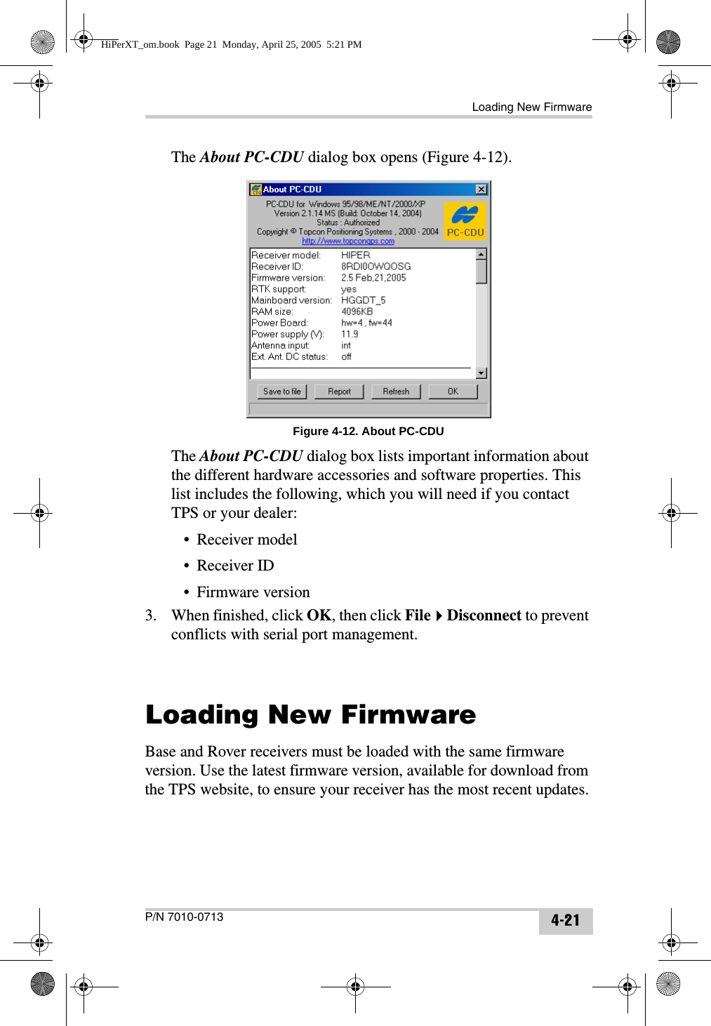
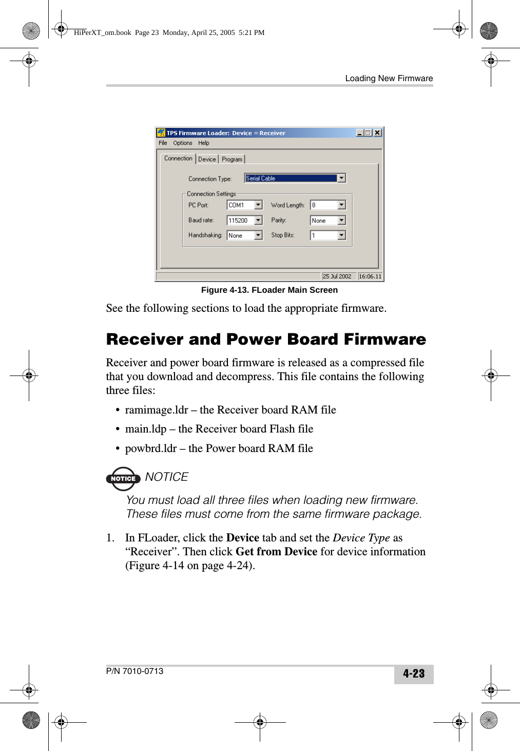
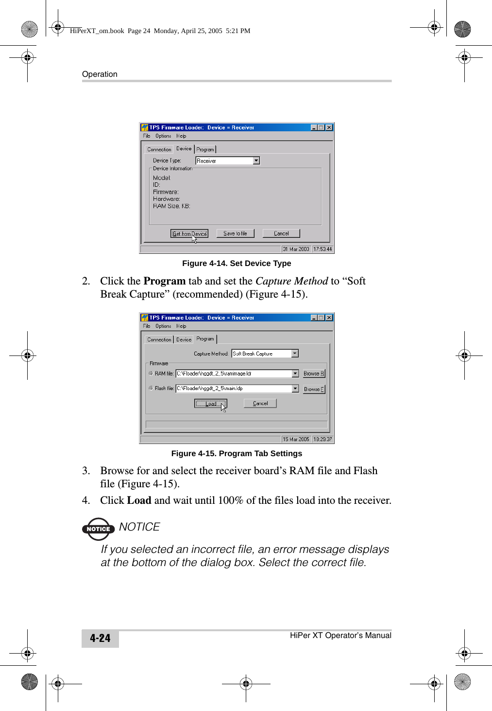
Topcon America 860801 GPS Survey Receiver User Manual HiPerXT om
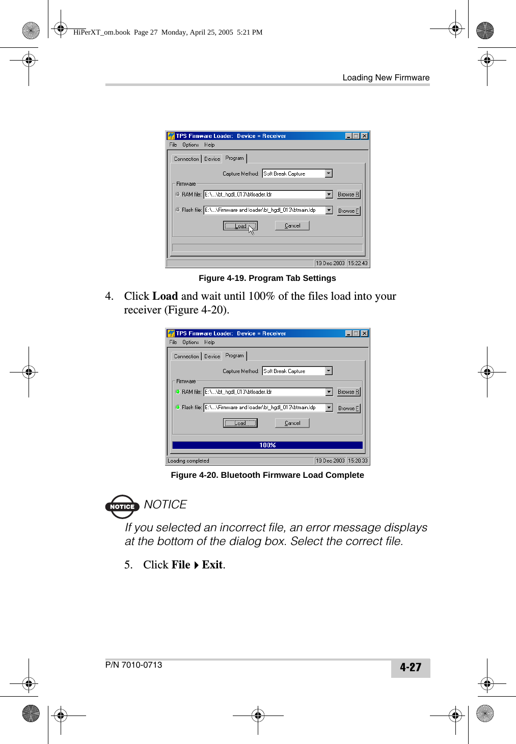
Topcon America Corporation GPS Survey Receiver HiPerXT om
UserManual.wiki
>
Topcon America
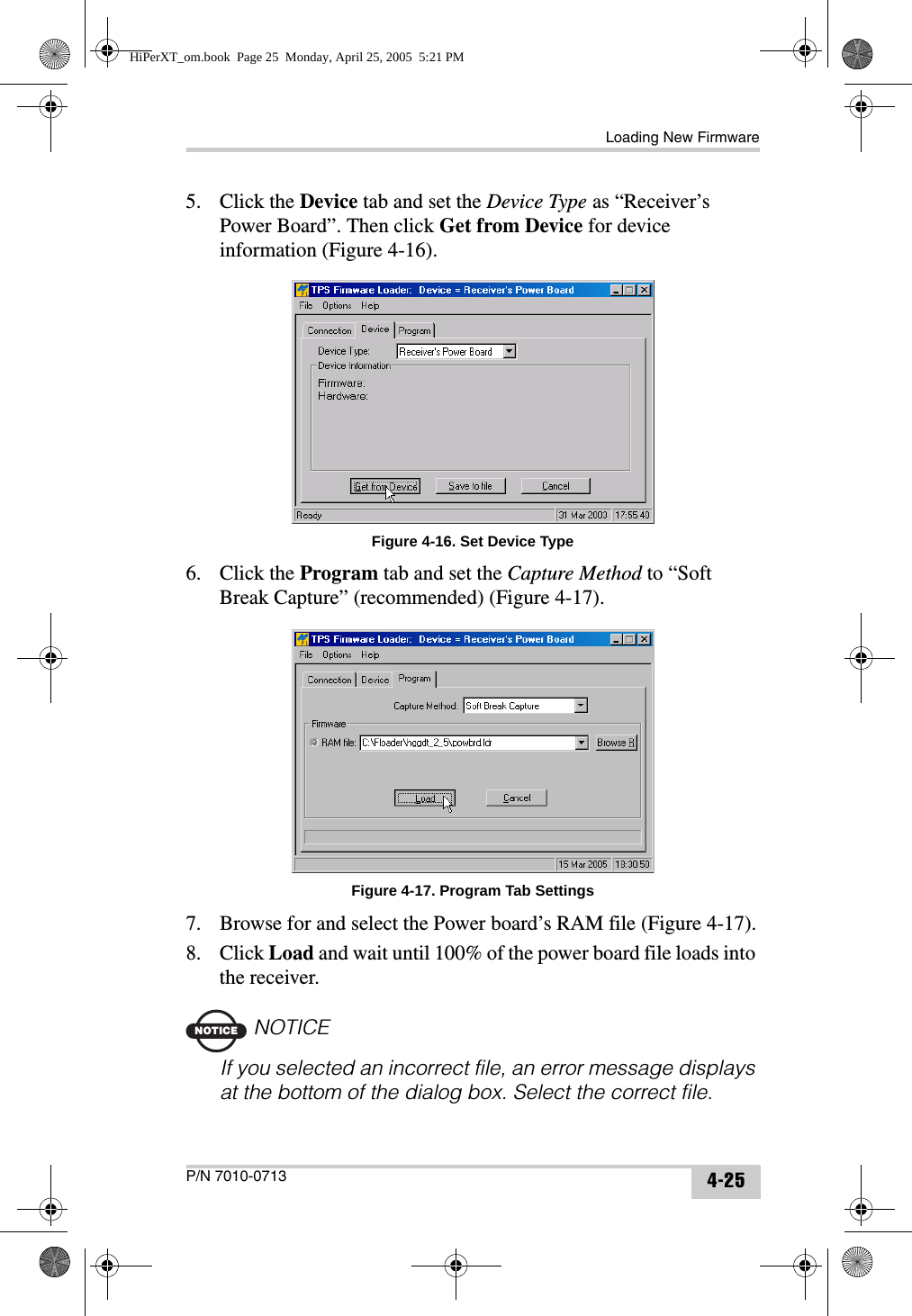
>
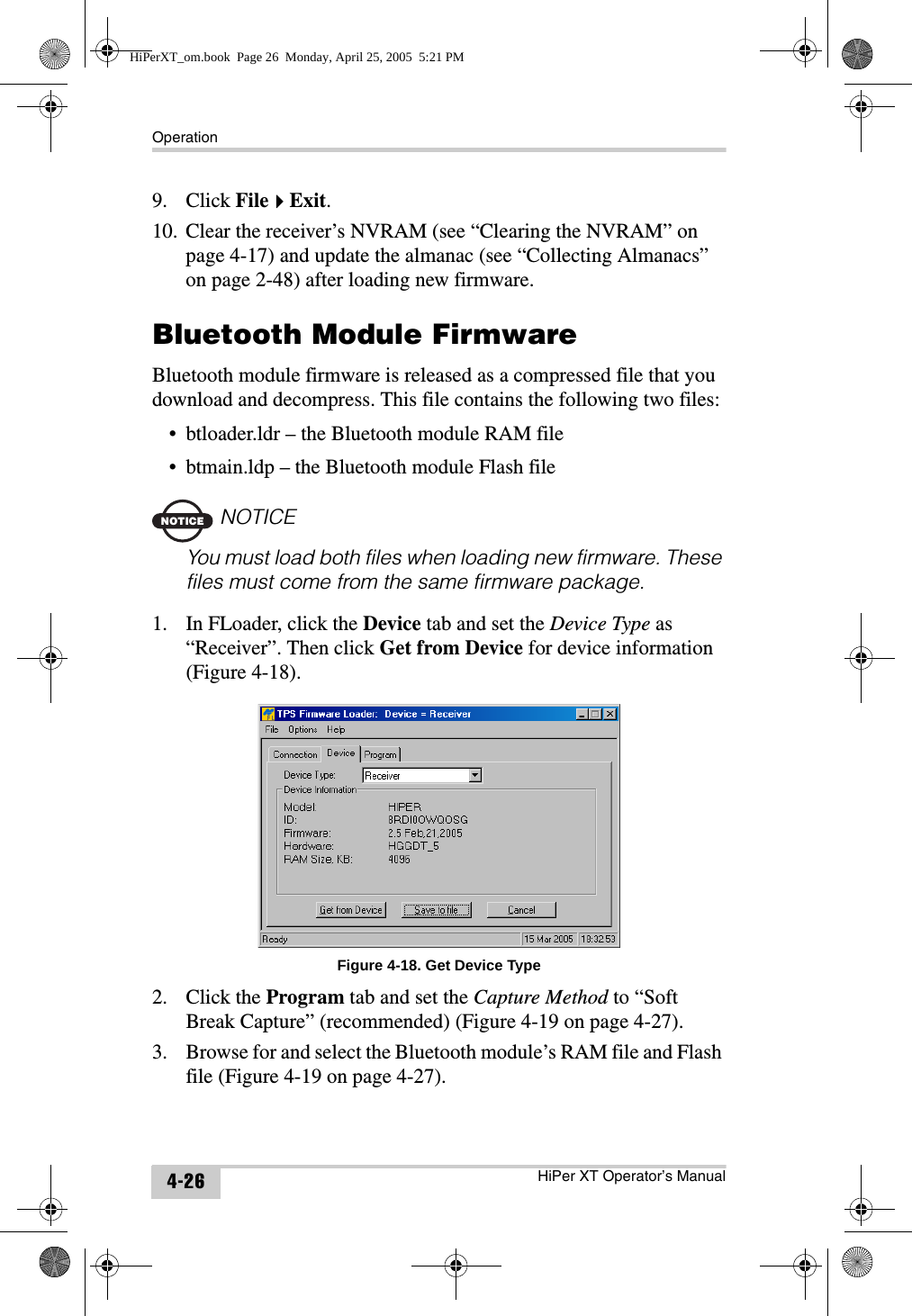
860801 User Manual
>
User manual part 2
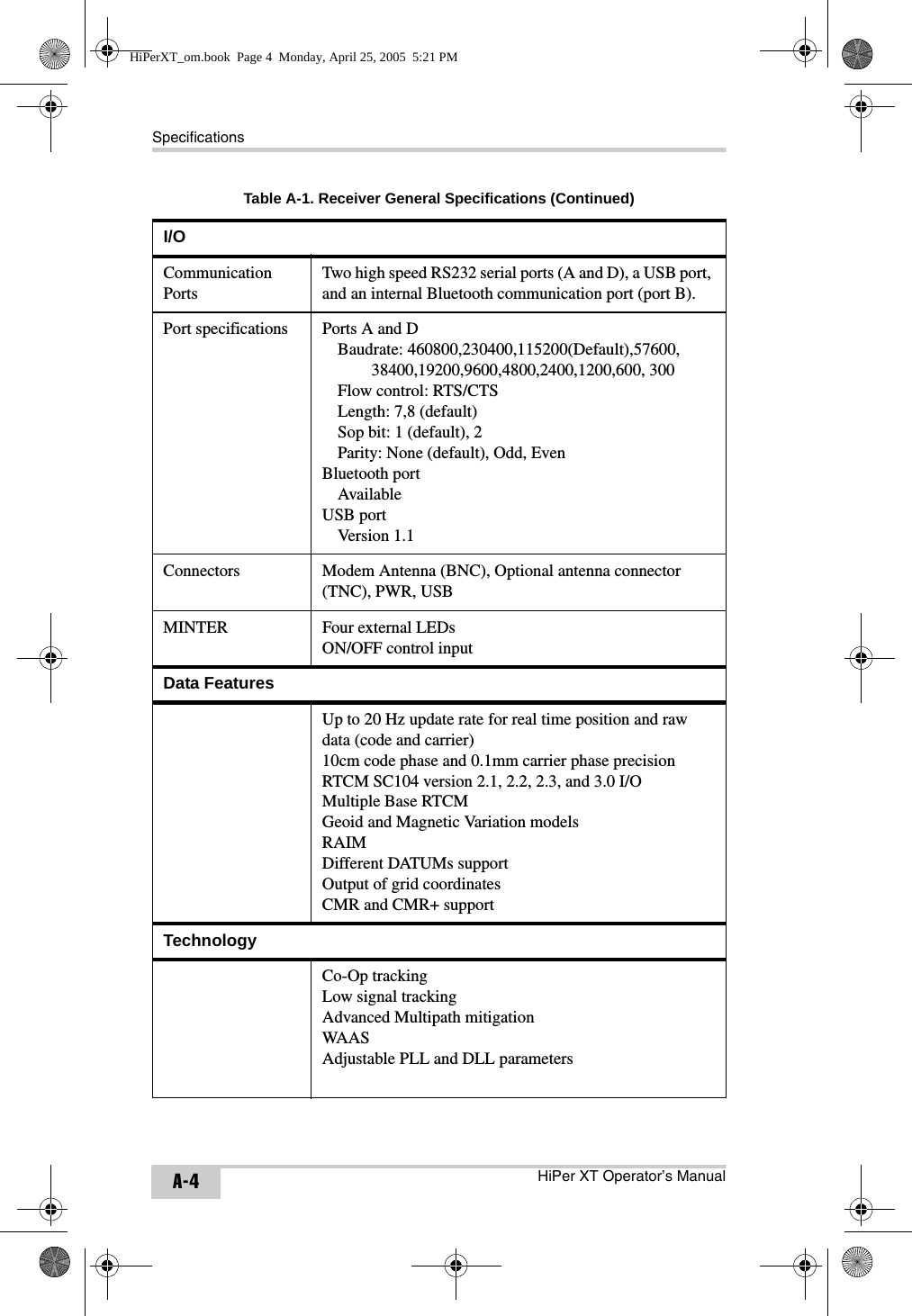
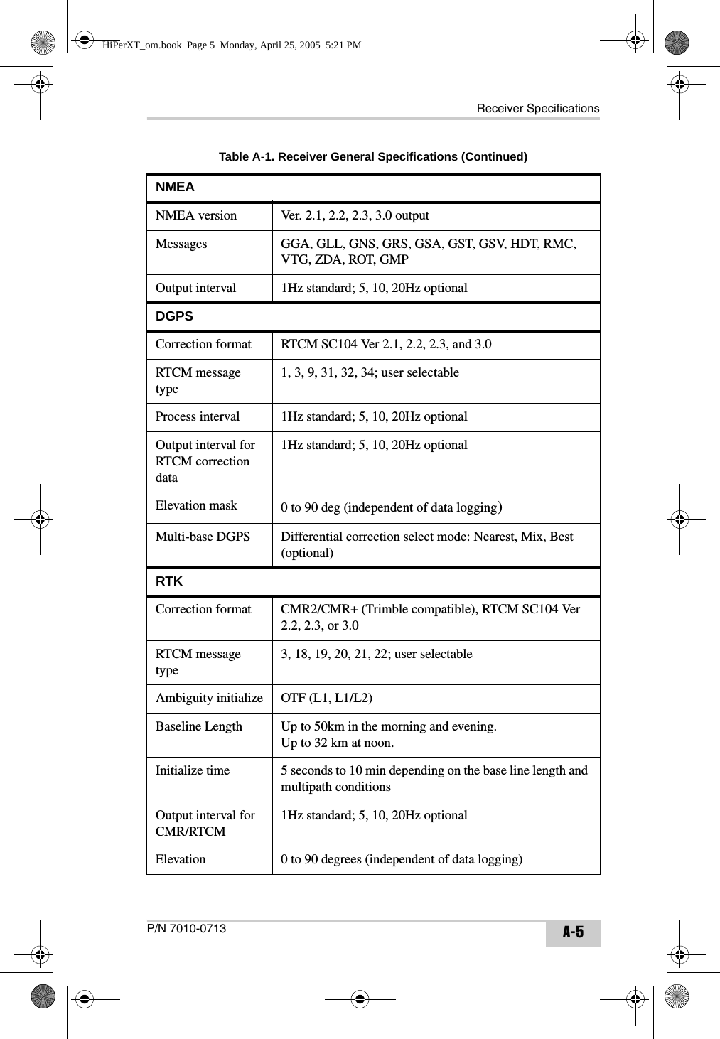
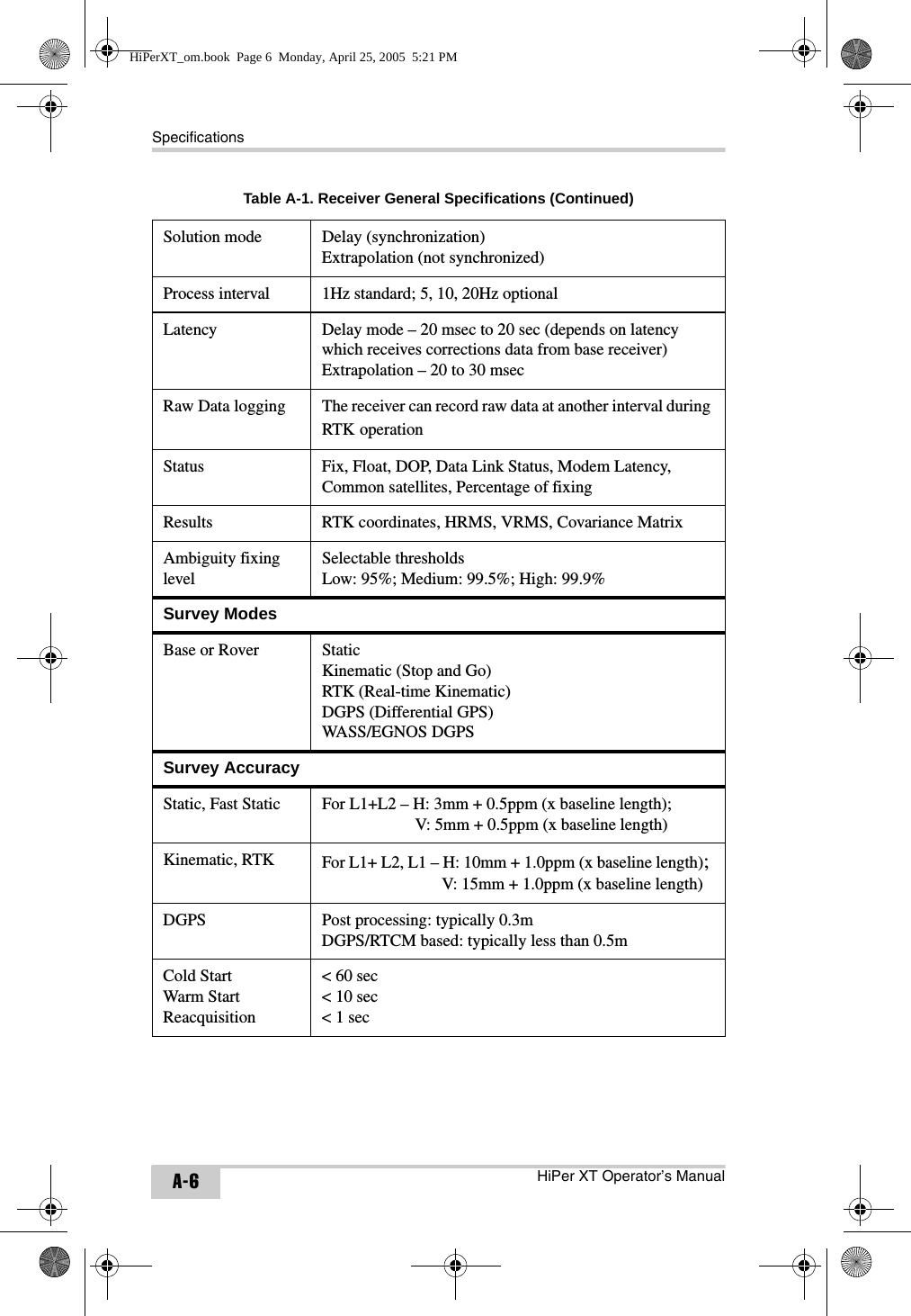
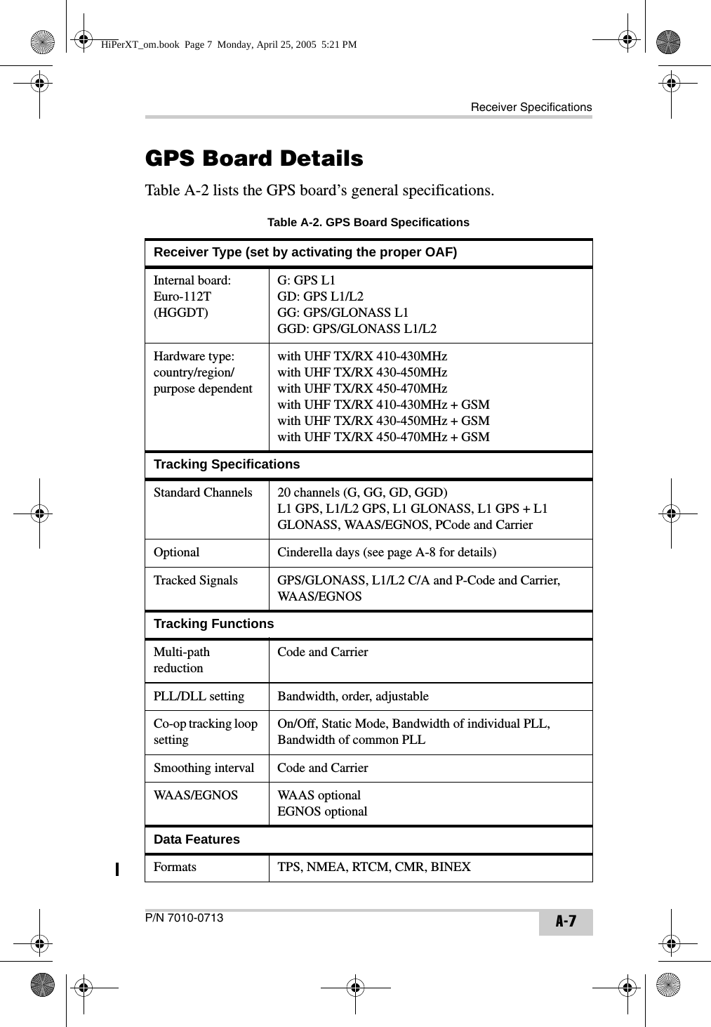
Contents
1.
User manual part 1
2.
User manual part 2
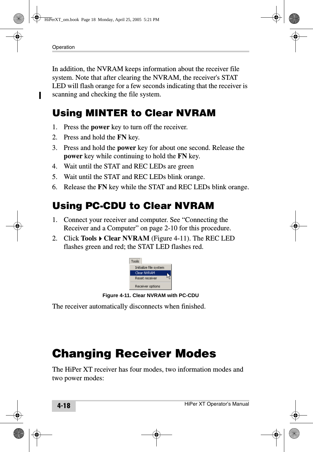
User manual part 2
Navigation menu
Upload a User Manual
Namespaces
Wiki Guide
HTML
PDF
Info
Views
User Manual
Discussion / Help
Navigation