Topcon America 860801 GPS Survey Receiver User Manual HiPerXT om
Topcon America Corporation GPS Survey Receiver HiPerXT om
Contents
- 1. User manual part 1
- 2. User manual part 2
User manual part 2

P/N 7010-0713
Chapter 4
4-1
Operation
This chapter describes standard receiver operating procedures:
•Using the MINTER
• Downloading receiver files to a computer
• Deleting files from the receiver
• Checking and loading OAFs
• Managing receiver memory
• Clearing the NVRAM
• Changing receiver modes
• Checking and loading firmware
Topcon receivers are built to operate independent of the receiver type.
Any minor exceptions for the HiPer XT are noted.
HiPerXT_om.book Page 1 Monday, April 25, 2005 5:21 PM

Operation
HiPer XT Operator’s Manual
4-2
Using the MINTER
The MINTER (Figure 4-1) is Topcon’s Minimum INTERface used to
display and control data input and output, and is the same for all
HiPer family receivers.
Figure 4-1. MINTER
Power Key
Pressing the power key turns the receiver on and off.
Status LED
• When the receiver is on and no satellites are tracked, the STAT
LED will blink red.
• When satellites are tracked, the STAT LED will produce one
blink for each tracked satellite (green for GPS, orange for
GLONASS).
Power Button Reset BATT
(battery LED)
RX
(modem status LED)
STAT (status LED)
FN (function/recording button)
REC (recording LED)
HiPerXT_om.book Page 2 Monday, April 25, 2005 5:21 PM

Using the MINTER
P/N 7010-0713 4-3
Reset Key
Pressing and holding the reset key for about one second causes:
• a hard reset of the receiver.
• the receiver to leave Zero Power Mode and return to Normal
Mode.
NOTICE
NOTICE
Only use this procedure if the receiver does not respond to
commands or does not charge the internal batteries (is in
Zero Power Mode).
FN Key and Record LED
Table 4-1 on page 4-5 summarizes FN key functions and REC LED
statuses. See “FN Key Mode parameter” on page 2-23 for information
on setting FN key modes.
• Pressing the FN key for less than one second switches the
receiver between different information modes (normal and
extended information), or between static and dynamic post-
processing modes, depending on the receiver's configuration.
During the first second of pressing the FN key, the REC LED is
orange.
• Pressing and holding the FN key for more than one and less than
five seconds will start/stop data recording.
During data recording the REC LED is green.
If the REC LED is red, the receiver has run out of memory, has a
hardware problem, or contains an improper OAF (see “Option
Authorization File (OAF)” on page 1-16 for more information on
OAFs).
• The REC LED blinks green each time data is written to the
internal receiver’s memory.
You set the data recording time interval using PC-CDU. See
“Recording Interval parameter” on page 2-20 for information on
setting this function.
HiPerXT_om.book Page 3 Monday, April 25, 2005 5:21 PM

Operation
HiPer XT Operator’s Manual
4-4
Each time you turn off or on data recording, either a new file
opens or data appends to a particular file. See “Always Append to
the File parameter” on page 2-21 and “Files Creation Mode
parameter” on page 2-21 for information on setting this function.
• Pressing and holding the FN key for more than five and less than
eight seconds will turn the baud rate of serial port A to 9600.
After about five seconds of pressing the FN key, the REC LED
becomes red. Release the FN key while the REC LED is red
(during the next three seconds).
Pressing and holding the FN key for more than eight seconds has
no impact.
• After loading new firmware or clearing the receiver’s NVRAM,
the receiver checks its internal file system.
During this operation, the REC LED flashes orange, and the file
system is not accessible for CDU (control display unit)
applications or for data recording. This operation may require
from fractions of a second to several minutes, depending on the
circumstances and the amount of internal memory.
HiPerXT_om.book Page 4 Monday, April 25, 2005 5:21 PM

Using the MINTER
P/N 7010-0713 4-5
Table 4-1. FN Key Functions and REC LED Status
FN Key REC LED Status
When data recording is off, and the FN key is...
Not pressed
No light No data recording.
Orange blink Internal file system test in progress.
Red No free memory; hardware problem
with data recording.
Pressed for < 1
second
If FN key mode is “LED blink mode switch”
Orange Release to change information mode.
If FN key mode is “Occupation mode switch”
Orange No function.
Pressed for 1–5
seconds
If FN key mode is “LED blink mode switch”
Green Release to start data recording (post-
processing occupation mode undefined).
If FN key mode is “Occupation mode switch”
Green Release to start recording (Kinematic or
Static post-processing occupation mode)
Pressed for 5–8
seconds
Red Release to turn serial port A baud rate to
9600 bps.
Pressed for > 8
seconds
No light No function.
HiPerXT_om.book Page 5 Monday, April 25, 2005 5:21 PM

Operation
HiPer XT Operator’s Manual
4-6
When data recording is on, and the FN key is...
Not pressed
Red No free memory; hardware problem
with data recording.
If FN key mode is “LED blink mode switch”
Green Data recording started (post-processing
occupation mode undefined).
If FN key mode is Occupation mode switch
Green Data recording started (Kinematic post-
processing occupation mode).
Orange Data recording started (Static post-
processing occupation mode).
Pressed for < 1
second
If FN key mode is “LED blink mode switch”
Orange Release to change information mode.
If FN key mode is “Occupation mode switch”
Orange Release to toggle between Static and
Kinematic post-processing modes.
Pressed for 1–5
seconds
No light Release to stop data recording.
Pressed for 5–8
seconds
Red Release to turn serial port A baud rate to
9600 bps.
Pressed for > 8
seconds
No light No function (data recording still on).
Table 4-1. FN Key Functions and REC LED Status (Continued)
FN Key REC LED Status
HiPerXT_om.book Page 6 Monday, April 25, 2005 5:21 PM

Using the MINTER
P/N 7010-0713 4-7
Battery LED
The color of the BATT LED indicates the level of internal battery
charge in the HiPer XT:
• Green – indicates greater than 85% charge.
• Orange – indicates an intermediate charge.
• Red – indicates less than 15% charge.
The pattern of blinks of the BATT LED also indicates the source of
power.
• Solid light – an external power supply is used and the batteries are
not being charged.
• Blinking once a second – the batteries are being charged.
• Blinking once every five seconds – the HiPer XT uses the internal
batteries for power.
• Not blinking – the receiver is in Zero Power Mode or the internal
batteries are completely discharged and no external power is
connected.
NOTICE
NOTICE
When the internal batteries have completely discharged
and no external power is connected, the receiver will go
into Zero Power Mode to prevent the batteries from over
discharging.
HiPerXT_om.book Page 7 Monday, April 25, 2005 5:21 PM

Operation
HiPer XT Operator’s Manual
4-8
Modem LED
The color of the TX/RX modem LED indicates if the modem has
power, is receiving signals, or is turned off.
For the UHF modem:
• No light – modem is turned off
• Solid Red – the modem is in transmitter mode; the modem is
transmitting data.
• Red flashes plus Green flashes – the modem is in command
mode. This mode allows the operator to send/query commands to/
from the modem.
• Solid Green – the modem is in receiver mode.
• Solid Orange (Red and Green) – the modem is receiving data.
• Red flashes – a fault condition has been detected. Check the
condition of the radio modem’s antenna to ensure it is
undamaged, and is connected properly and securely. Also make
sure that there are no conduction objects near the antenna
location.
For the GSM modem:
• Solid Orange (Red and Green) – the modem is initializing.
• Green flashes – the modem is on, registered on the network, and
is waiting for incoming calls (Slave mode).
• Solid Red – a connection has been established.
• Green flashes – the modem is in direct control mode (Daisy
Chain).
• Orange flashes – an error has occurred (initialization error, wrong
PIN code, etc.).
HiPerXT_om.book Page 8 Monday, April 25, 2005 5:21 PM

Using the MINTER
P/N 7010-0713 4-9
Information Modes
The receiver has two information modes: Normal and Extended
Information Mode (EIM).
Normal
In normal mode, the STAT LED indicates the number of tracked
satellites and the position’s computation status.
Extended Information Mode (EIM)
Extended Information Mode (EIM) is used for receiver testing
purposes. In this mode, the receiver continues to work as usual, but
the STAT LED indicates “extended” information using a delimiter.
The Delimiter is a distinguishable double-blink that shows the overall
status of tests performed in EIM. The LED color for delimiter is
calculated from the colors of other LED blinks, and will be one of the
following colors when the tests complete:
• Orange – at least one blink is orange.
• Red – no orange blink and at least one red blink.
• Green – all other cases.
The delimiter double-blink is followed by six LED blinks
corresponding to six receiver tests, where each blink indicates the
following information:
Blink 1. Sufficient data for position computation.
Blink 2. GPS S/N ratios are good (Table 4-2 on page 4-10).
Blink 3. GLONASS S/N ratios are good (Table 4-2 on page 4-
10).
Blink 4. Oscillator’s frequency offset is less than three ppm.
Blink 5. Oscillator's Allan Variance is better than 2.7e-10.
Blink 6. Continuous tracking time is more than 15 minutes.
HiPerXT_om.book Page 9 Monday, April 25, 2005 5:21 PM

Operation
HiPer XT Operator’s Manual
4-10
The color of the blink indicates that information for test is unavailable
(orange), the receiver passed the test (green), or the receiver failed the
test (red).
1. To switch to EIM, press and quickly release (within one second)
the FN key on the MINTER.
2. Watch for the delimiter double-blink. With good receiver,
antenna, and observation conditions, all blinks should be green
within 15 minutes of powering on.
• Green – ok
• Orange – wait
• Red – some tests failed
3. To switch back to normal mode, press the FN key.
Downloading Files to a
Computer
When your survey finishes, you can download survey files to a
computer for storage, post-processing, or backup. Also, the receiver
memory holds a finite amount of files and information, so
downloading the files prevents files from being lost.
You should download files as soon as possible after collecting data at
the jobsite. PC-CDU provides a File Manager to download files to
your computer and delete files from the receiver.
1. Connect your receiver and computer. See “Connecting the
Receiver and a Computer” on page 2-10 for this procedure.
Table 4-2. Signal-to-Noise (S/N) “Good” Ratios
CA/L1 P/L1 P/L2
GPS513939
GLONASS 51 49 40
HiPerXT_om.book Page 10 Monday, April 25, 2005 5:21 PM
Downloading Files to a Computer
P/N 7010-0713 4-11
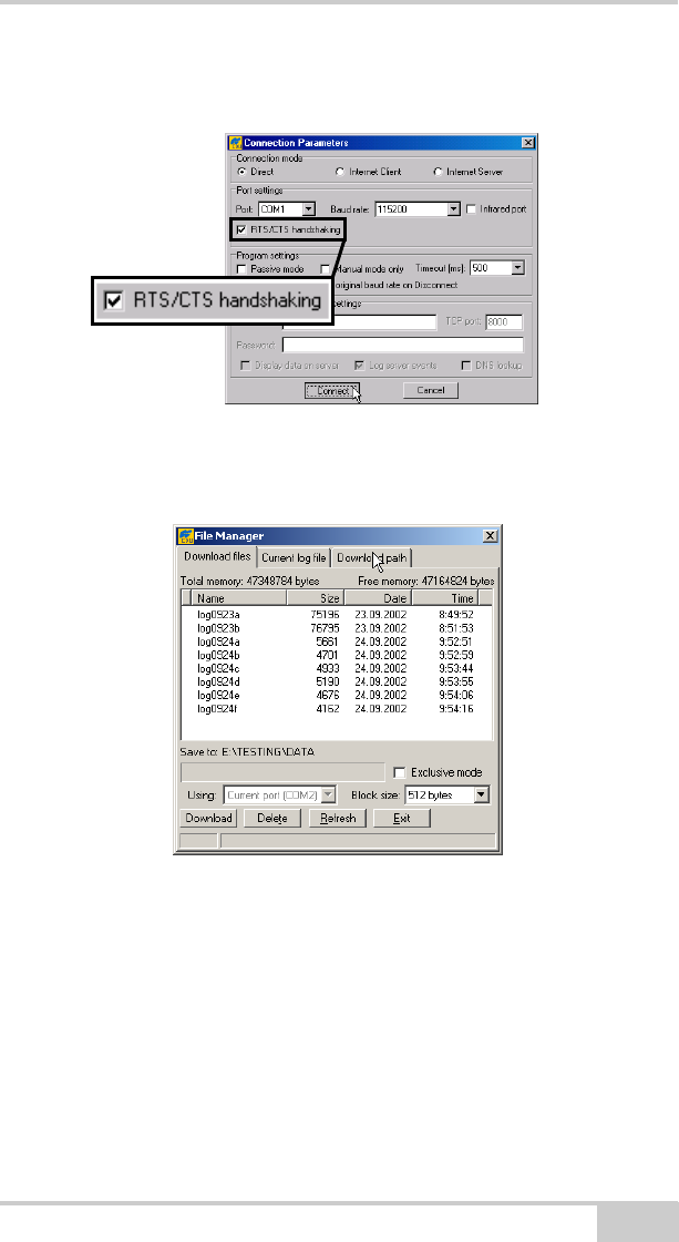
2. On the Connection Parameters dialog box, enable RTS/CTS
handshaking and click Connect (Figure 4-2).
Figure 4-2. Connection Parameters – RTS/CTS Handshaking
3. Click FileFile Manager, then click the Download path tab on
the File Manager dialog box (Figure 4-3).
Figure 4-3. Find Files to Download
4. Navigate to or create (using the Create button) the folder in
which to download and store files.
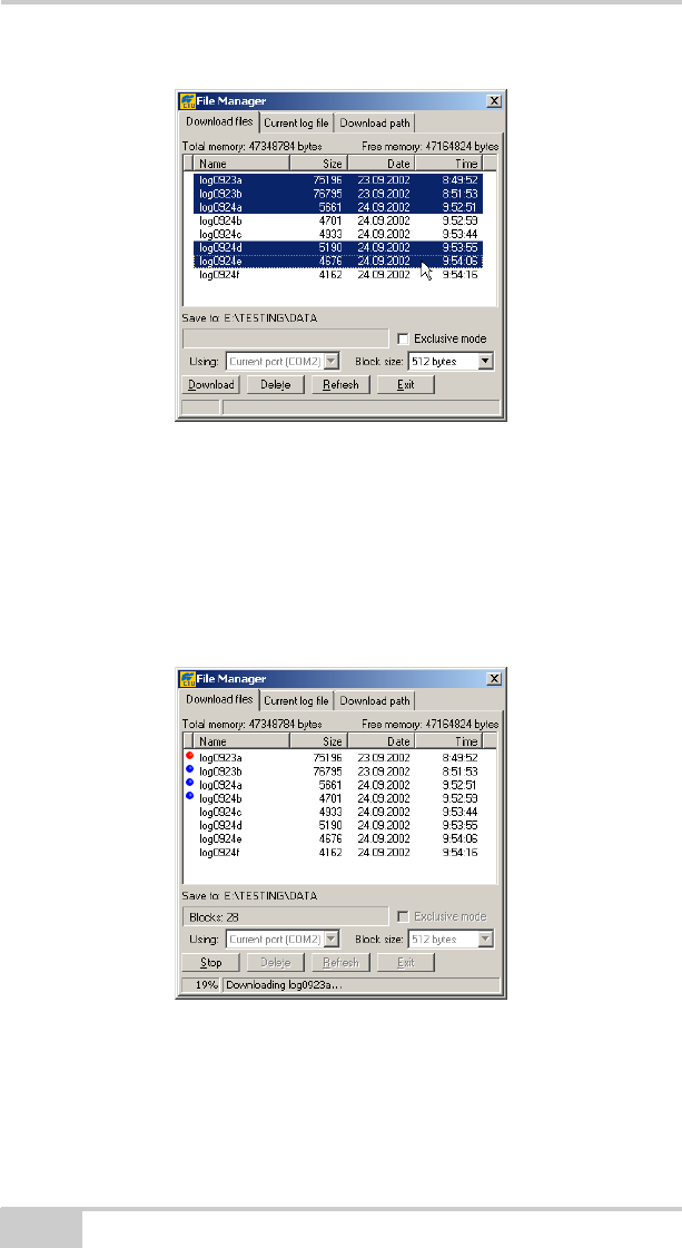
5. Click the Download files tab and select the file(s) to download
(Figure 4-4 on page 4-12).
To select multiple files, hold down the shift key and click on non-
sequential files to select several files at once; or, hold down the
Ctrl key and click on individual files.
HiPerXT_om.book Page 11 Monday, April 25, 2005 5:21 PM
Operation
HiPer XT Operator’s Manual
4-12
Figure 4-4. Download Files
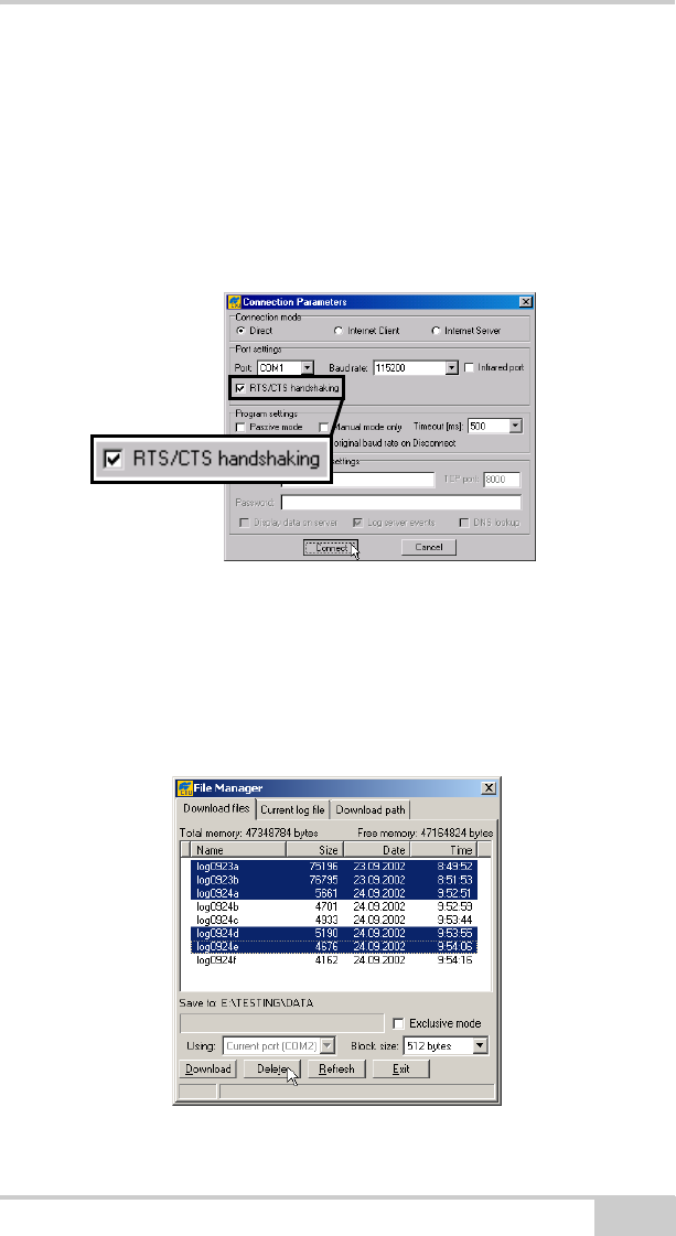
6. Click the Download button. During the download, status
indicators display next to each file (Figure 4-5).
• Blue indicator – file in queue for downloading.
• Red indicator – file currently downloading.
• Green indicator – file has successfully downloaded.
Figure 4-5. Download Files – Status Indicators
7. Click Exit on the File Manager dialog box.
8. Continue with other operations. Or, click FileDisconnect, then
FileExit to quit PC-CDU.
HiPerXT_om.book Page 12 Monday, April 25, 2005 5:21 PM
Deleting Files
P/N 7010-0713 4-13
Deleting Files
Use the following steps to delete files from your receiver.
1. Connect your receiver and computer. See “Connecting the
Receiver and a Computer” on page 2-10 for this procedure.
2. On the Connection Parameters dialog box, enable RTS/CTS
handshaking (Figure 4-6).
Figure 4-6. Connection Parameters – RTS/CTS Handshaking
3. Click FileFile Manager and select the file(s) to delete on the
Download files tab (Figure 4-7).
To select multiple files, hold down the shift key and click on non-
sequential files to select several files at once; or hold down the
Ctrl key and click on individual files.
Figure 4-7. Delete Files
HiPerXT_om.book Page 13 Monday, April 25, 2005 5:21 PM
Operation
HiPer XT Operator’s Manual
4-14
4. Click Delete (Figure 4-7 on page 4-13).
5. Click Ye s at the delete files confirmation dialog box. PC-CDU
deletes the selected files.
6. Click Exit on the File Manager screen.
7. Continue with other operations. Or Click FileDisconnect, then
FileExit to quit PC-CDU.
Checking Receiver Options
TIP TIP
For a complete list of options and their details, visit the
Topcon website.
You can check the status of your receiver’s options, and load any new
OAFs, using the RS232 cable, a computer, and PC-CDU. Refer to the
PC-CDU User’s Manual for a more complete description of the
PC-CDU software.
1. Connect your receiver and computer. See “Connecting the
Receiver and a Computer” on page 2-10 for this procedure.
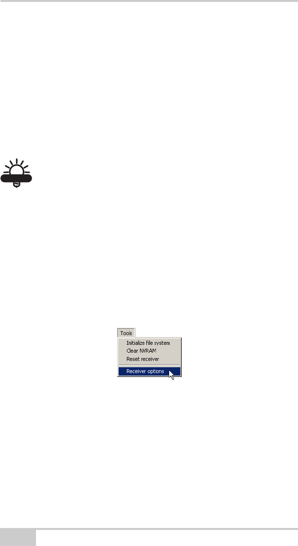
2. Click ToolsReceiver Options (Figure 4-8).
Figure 4-8. Open Receiver Options
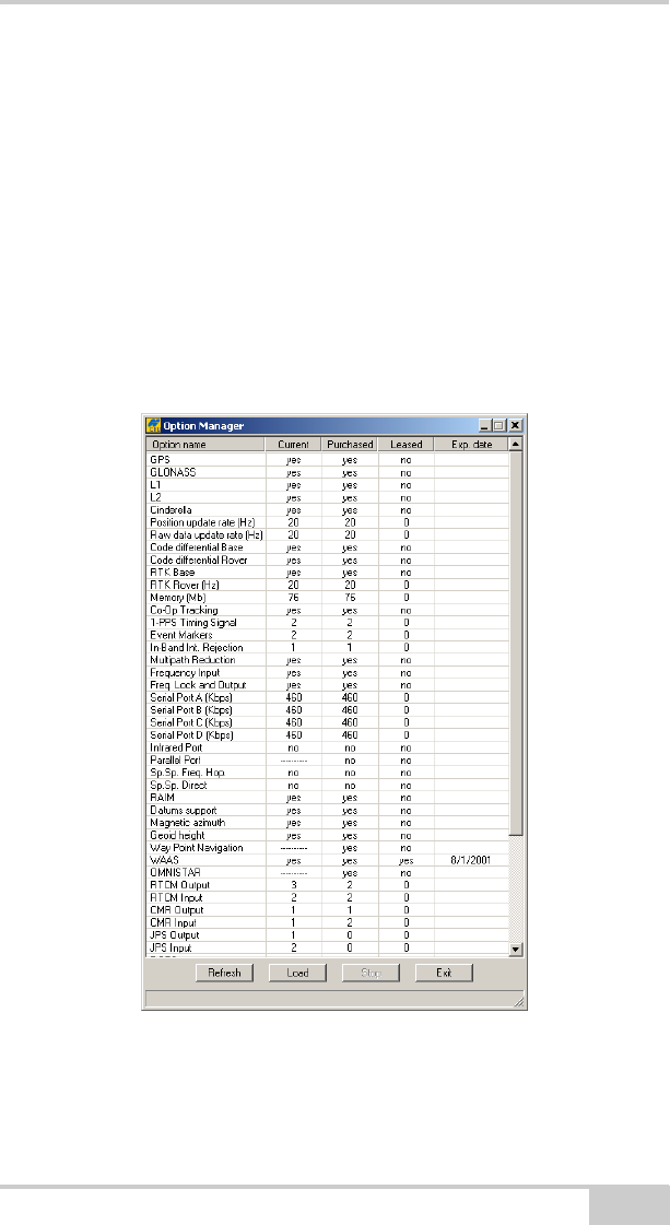
The Options Manager dialog box (Figure 4-9 on page 4-15)
contains the following information:
• Option name – a name/description of the option
• Current – the current status of the option
• Purchased – if the option is purchased or not
• Leased – if the option is leased or not
HiPerXT_om.book Page 14 Monday, April 25, 2005 5:21 PM
Checking Receiver Options
P/N 7010-0713 4-15
• Expiration date – the date the option will be disabled, if
applicable
Since Options can be both purchased and leased, the “Current”
status of the option displays the currently effective value. Option
values can be:
• -1 or “-----” – the firmware version does not support this
option.
• 0 – the receiver option is disabled.
• positive integer – the option is enabled.
• yes or no – the option is either enabled or disabled.
Figure 4-9. Option Manager
3. When finished, click Exit on the Option Manager screen, then
click FileDisconnect to prevent conflicts with serial port
management.
HiPerXT_om.book Page 15 Monday, April 25, 2005 5:21 PM
Operation
HiPer XT Operator’s Manual
4-16
Loading OAFs
Topcon Positioning System dealers provide customers with OAF
files. For any OAF related questions, E-mail TPS at
options@topconps.com. Please have your receiver ID number
available (see “Checking Firmware Version” on page 4-20).
1. To load a new OAF, follow steps one and two in “Checking
Receiver Options” on page 4-14.
2. Click Load at the bottom of the Option Manager dialog box (see
Figure 4-9 on page 4-15).
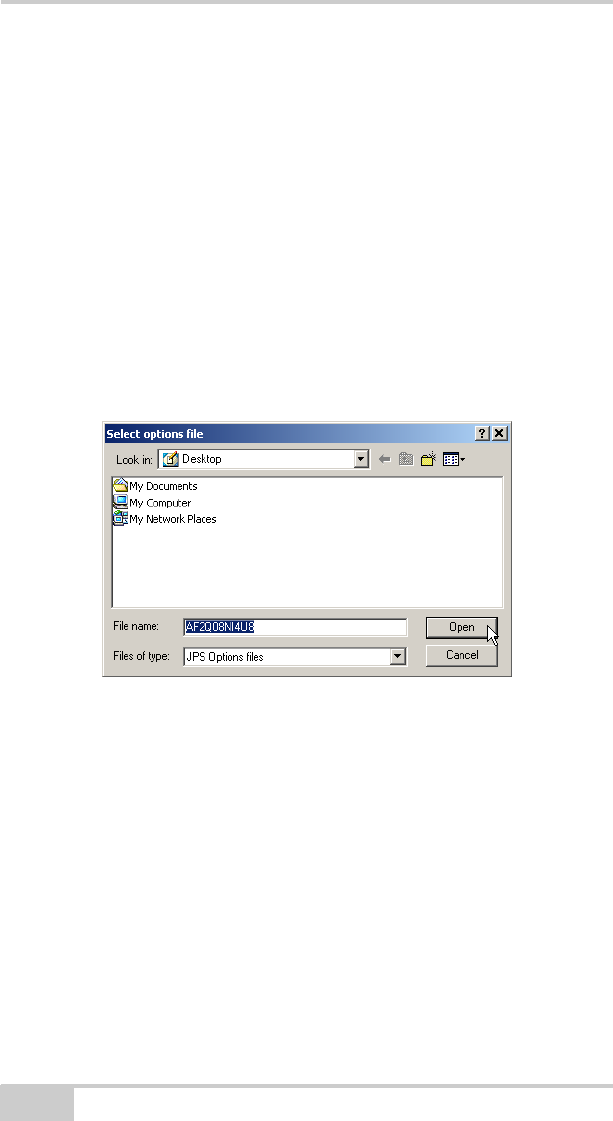
3. Navigate to the location of the new Option Authorization File.
OAFs have .jpo or .tpo extensions and are unique to each receiver
(Figure 4-10).
Figure 4-10. Load OAF
4. Select the appropriate file and click Open (Figure 4-10). The new
receiver option loads onto the receiver and the Option Manager
table updates.
5. When finished, click Exit on the Option Manager dialog box,
then click FileDisconnect to prevent conflicts with serial port
management.
HiPerXT_om.book Page 16 Monday, April 25, 2005 5:21 PM

Managing Receiver Memory
P/N 7010-0713 4-17
Managing Receiver Memory
When using the receiver in static or dynamic applications, you may
need to know the amount of memory the receiver’s log file occupies.
The specific memory size depends on the type of data being recorded.
Use the formulas below to compute the approximate size of the
receiver’s log files. These equations are based on the default set of
messages.
• SS – the estimated size of one epoch of raw data in the receiver’s
log file (expressed in bytes).
• N – the number of observed satellites per epoch.
When recording only L1 data:
SS = 183 + 22*N
When recording L1 and L2 data:
SS = 230 + 44*N
Clearing the NVRAM
The receiver’s Non-Volatile Random Access Memory (NVRAM)
holds data required for satellite tracking, such as ephemeris data and
receiver position. The NVRAM also keeps the current receiver’s
settings, such as active antenna input, elevation masks and recording
interval, and information about the receiver’s internal file system.
Even though clearing the NVRAM is not a common (nor normally a
recommended) operation, there are times when clearing the NVRAM
can eliminate communication or tracking problems. Clearing the
NVRAM in your receiver can be interpreted as a “soft boot” in your
computer.
After clearing the NVRAM, your receiver will require some time to
collect new ephemerides and almanacs (around 15 minutes).
Clearing the NVRAM of your receiver will not delete any files
already recorded in your HiPer XT’s memory. However, it will reset
your receiver to factory default values.
HiPerXT_om.book Page 17 Monday, April 25, 2005 5:21 PM

Operation
HiPer XT Operator’s Manual
4-18
In addition, the NVRAM keeps information about the receiver file
system. Note that after clearing the NVRAM, the receiver's STAT
LED will flash orange for a few seconds indicating that the receiver is
scanning and checking the file system.
Using MINTER to Clear NVRAM
1. Press the power key to turn off the receiver.
2. Press and hold the FN key.
3. Press and hold the power key for about one second. Release the
power key while continuing to hold the FN key.
4. Wait until the STAT and REC LEDs are green
5. Wait until the STAT and REC LEDs blink orange.
6. Release the FN key while the STAT and REC LEDs blink orange.
Using PC-CDU to Clear NVRAM
1. Connect your receiver and computer. See “Connecting the
Receiver and a Computer” on page 2-10 for this procedure.
2. Click ToolsClear NVRAM (Figure 4-11). The REC LED
flashes green and red; the STAT LED flashes red.
Figure 4-11. Clear NVRAM with PC-CDU
The receiver automatically disconnects when finished.
Changing Receiver Modes
The HiPer XT receiver has four modes, two information modes and
two power modes:
HiPerXT_om.book Page 18 Monday, April 25, 2005 5:21 PM

Changing Receiver Modes
P/N 7010-0713 4-19
• Normal Mode
• Extended Information Mode
• Sleep Mode
•Zero Power Mode
See “Information Modes” on page 4-9 for a description of Normal
Mode and Extended Information Mode.
Sleep Mode
In sleep mode, the power board and Bluetooth module will continue
to draw power from the batteries, causing the batteries to drain over
time. Put the receiver in Zero Power Mode to prevent this (see “Zero
Power Mode” on page 4-19). Follow these steps to put the HiPer XT
into sleep mode.
1. Turn on your receiver.
2. Press and hold the receiver’s power key for more than four
seconds and less than eight seconds.
3. Release the power key when both the REC and STAT LEDs
become orange. The receiver enters Sleep Mode.
4. Any activity on the RS232 port will turn the receiver on.
NOTICE
NOTICE
If you press and hold the power key for more than 14
seconds, it will be ignored. This protects receiver operation
against stuck keys.
Zero Power Mode
When your receiver is off, even in Sleep Mode, the power board will
continue to draw power from the batteries. This means that if you
fully charge your receiver, turn it off and store it, the receiver will
drain its battery power in less than two months. To stop the power
HiPerXT_om.book Page 19 Monday, April 25, 2005 5:21 PM

Operation
HiPer XT Operator’s Manual
4-20
board from draining the batteries, you can put your receiver in Zero
Power Mode.
1. Turn on your receiver.
2. Press and hold the power key for more than 8 seconds, but less
than 14 seconds.
3. Release the power key when both LEDs become red. When the
LEDs turn off, your receiver will be in Zero Power Mode.
4. Press the Reset key for about one second to return to Normal
mode.
NOTICE
NOTICE
When the internal batteries have completely discharged
and no external power is connected, the receiver will go
into Zero Power Mode automatically to prevent the
batteries from over discharging.
Checking Firmware Version
Use PC-CDU to check the firmware version of the receiver.
1. Connect the receiver and a computer. See “Connecting the
Receiver and a Computer” on page 2-10 for this procedure.
2. Click HelpAbout.
HiPerXT_om.book Page 20 Monday, April 25, 2005 5:21 PM
Loading New Firmware
P/N 7010-0713 4-21
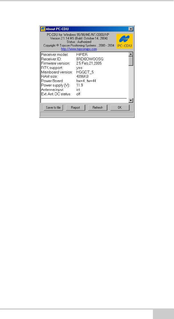
The About PC-CDU dialog box opens (Figure 4-12).
Figure 4-12. About PC-CDU
The About PC-CDU dialog box lists important information about
the different hardware accessories and software properties. This
list includes the following, which you will need if you contact
TPS or your dealer:
• Receiver model
• Receiver ID
• Firmware version
3. When finished, click OK, then click FileDisconnect to prevent
conflicts with serial port management.
Loading New Firmware
Base and Rover receivers must be loaded with the same firmware
version. Use the latest firmware version, available for download from
the TPS website, to ensure your receiver has the most recent updates.
HiPerXT_om.book Page 21 Monday, April 25, 2005 5:21 PM

Operation
HiPer XT Operator’s Manual
4-22
NOTICE
NOTICE
The HiPer XT receiver should be loaded with firmware
version 2.5 or newer.
CAUTION
CAUTION
Do not use firmware versions 2.4 or older.
The receiver board and power board must be loaded with firmware
from the same package. The Bluetooth module’s firmware is
independent of the receiver card and power board, and has a different
firmware package.
The receiver uses FLoader, a Windows®-based utility, to load
firmware onto the receiver and power boards. You can download
FLoader to your computer from the TPS website. For more
information, refer to the FLoader User’s Manual, also available on
the TPS website.
1. Download and install FLoader, if applicable.
2. Download the new firmware package to your computer.
3. Connect your receiver and computer. See “Connecting the
Receiver and a Computer” on page 2-10 for this procedure.
4. Activate FLoader.
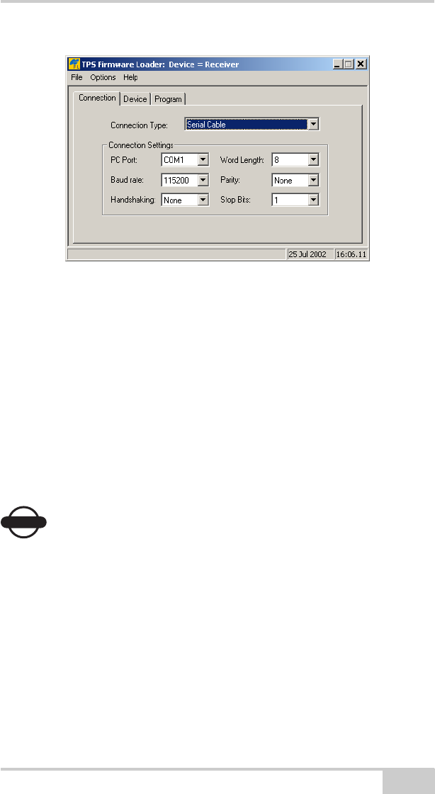
5. On the Connection tab, select the COM port on your computer
that connects with your receiver and select its speed (usually
115200) (Figure 4-13 on page 4-23).
HiPerXT_om.book Page 22 Monday, April 25, 2005 5:21 PM
Loading New Firmware
P/N 7010-0713 4-23
Figure 4-13. FLoader Main Screen
See the following sections to load the appropriate firmware.
Receiver and Power Board Firmware
Receiver and power board firmware is released as a compressed file
that you download and decompress. This file contains the following
three files:
• ramimage.ldr – the Receiver board RAM file
• main.ldp – the Receiver board Flash file
• powbrd.ldr – the Power board RAM file
NOTICE
NOTICE
You must load all three files when loading new firmware.
These files must come from the same firmware package.
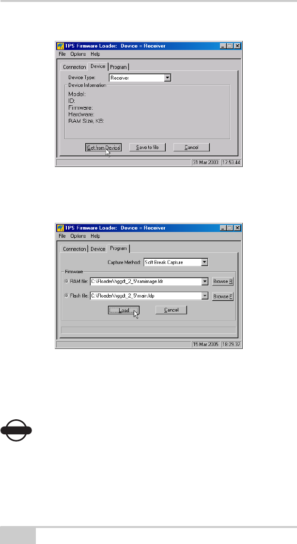
1. In FLoader, click the Device tab and set the Device Type as
“Receiver”. Then click Get from Device for device information
(Figure 4-14 on page 4-24).
HiPerXT_om.book Page 23 Monday, April 25, 2005 5:21 PM
Operation
HiPer XT Operator’s Manual
4-24
Figure 4-14. Set Device Type
2. Click the Program tab and set the Capture Method to “Soft
Break Capture” (recommended) (Figure 4-15).
Figure 4-15. Program Tab Settings
3. Browse for and select the receiver board’s RAM file and Flash
file (Figure 4-15).
4. Click Load and wait until 100% of the files load into the receiver.
NOTICE
NOTICE
If you selected an incorrect file, an error message displays
at the bottom of the dialog box. Select the correct file.
HiPerXT_om.book Page 24 Monday, April 25, 2005 5:21 PM
Loading New Firmware
P/N 7010-0713 4-25
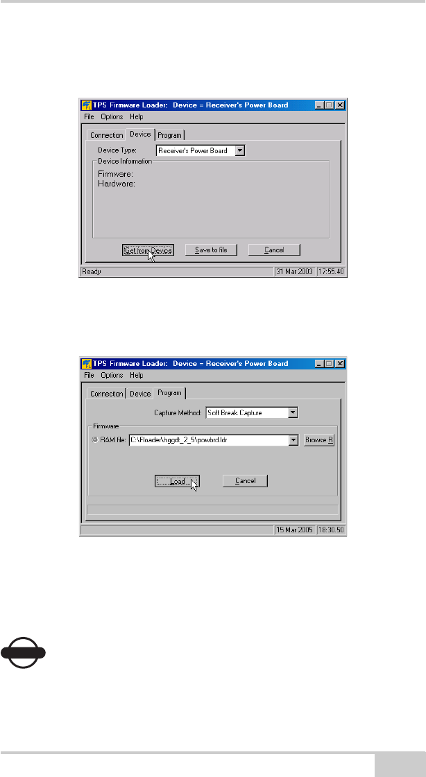
5. Click the Device tab and set the Device Type as “Receiver’s
Power Board”. Then click Get from Device for device
information (Figure 4-16).
Figure 4-16. Set Device Type
6. Click the Program tab and set the Capture Method to “Soft
Break Capture” (recommended) (Figure 4-17).
Figure 4-17. Program Tab Settings
7. Browse for and select the Power board’s RAM file (Figure 4-17).
8. Click Load and wait until 100% of the power board file loads into
the receiver.
NOTICE
NOTICE
If you selected an incorrect file, an error message displays
at the bottom of the dialog box. Select the correct file.
HiPerXT_om.book Page 25 Monday, April 25, 2005 5:21 PM
Operation
HiPer XT Operator’s Manual
4-26
9. Click FileExit.
10. Clear the receiver’s NVRAM (see “Clearing the NVRAM” on
page 4-17) and update the almanac (see “Collecting Almanacs”
on page 2-48) after loading new firmware.
Bluetooth Module Firmware
Bluetooth module firmware is released as a compressed file that you
download and decompress. This file contains the following two files:
• btloader.ldr – the Bluetooth module RAM file
• btmain.ldp – the Bluetooth module Flash file
NOTICE
NOTICE
You must load both files when loading new firmware. These
files must come from the same firmware package.
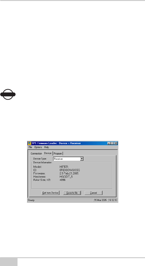
1. In FLoader, click the Device tab and set the Device Type as
“Receiver”. Then click Get from Device for device information
(Figure 4-18).
Figure 4-18. Get Device Type
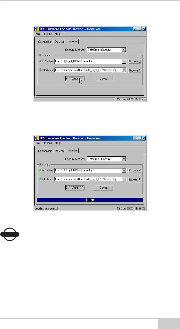
2. Click the Program tab and set the Capture Method to “Soft
Break Capture” (recommended) (Figure 4-19 on page 4-27).
3. Browse for and select the Bluetooth module’s RAM file and Flash
file (Figure 4-19 on page 4-27).
HiPerXT_om.book Page 26 Monday, April 25, 2005 5:21 PM
Loading New Firmware
P/N 7010-0713 4-27
Figure 4-19. Program Tab Settings
4. Click Load and wait until 100% of the files load into your
receiver (Figure 4-20).
Figure 4-20. Bluetooth Firmware Load Complete
NOTICE
NOTICE
If you selected an incorrect file, an error message displays
at the bottom of the dialog box. Select the correct file.
5. Click FileExit.
HiPerXT_om.book Page 27 Monday, April 25, 2005 5:21 PM

Operation
HiPer XT Operator’s Manual
Notes:
4-28
HiPerXT_om.book Page 28 Monday, April 25, 2005 5:21 PM

P/N 7010-0713
Chapter 5
5-1
Troubleshooting
In general, as long as you follow the maintenance and safety
instructions provided in this manual, you should have few problems
with your receiver. This chapter will help you diagnose and solve
some common problems you may encounter with your receiver.
WARNING
WARNING
Do not attempt to repair equipment yourself. Doing so
will void your warranty and may damage the hardware.
Check This First!
Before contacting TPS Customer support about any problems with
the receiver, try the following:
• First, check all external receiver connections carefully to ensure
correct and secure connections.
• Second, double check for worn or defective cables.
• Next, see the sections below for more specific solutions.
If the problem persists, try the following:
• Reset the receiver using PC-CDU (ToolsReset receiver).
• Restore default settings using PC-CDU (Configuration
Receiver, then click Set all parameters to defaults).
• Clear the NVRAM (see “Clearing the NVRAM” on page 4-17).
• Initialize the file system (click ToolsInitialize file system).
This will erase all files inside the receiver.
HiPerXT_om.book Page 1 Monday, April 25, 2005 5:21 PM
Troubleshooting
HiPer XT Operator’s Manual
5-2
Power Problems
All receivers are preset in the factory as “Auto Mode” for both the
power and charger. If you want to check these settings, use the
following procedure:
1. Connect your receiver and computer and run PC-CDU (see
“Connecting the Receiver and a Computer” on page 2-10).
2. Once connected, click ConfigurationReceiver.
3. On the General tab, view the Power and Charger fields. These
fields should be set to “Auto”. If not, change them to Auto and
click Apply.
TIP TIP
Clearing the NVRAM will also return the receiver to Auto
Mode (see “Clearing the NVRAM” on page 4-17).
Problem
The receiver does not power up.
Causes Solutions
The receiver may be in
Zero Power Mode.
Press the Reset key.
If no external power
source used, batteries
may be discharged.
Connect a fully charged external power
source and retry. See “Powering the
Receiver” on page 2-2.
The receiver has an
external power source,
but internal batteries
are discharged.
Charge the batteries overnight. See
“Powering the Receiver” on page 2-2.
The receiver may have
a defective charger or
defective internal
batteries.
If after charging your internal batteries
overnight, and your receiver is not
powering, contact TPS Customer Support
for advice.
HiPerXT_om.book Page 2 Monday, April 25, 2005 5:21 PM

Receiver Problems
P/N 7010-0713 5-3
Receiver Problems
The following are some of the most commonly encountered receiver
problems.
Problem
The receiver cannot establish a connection to a computer or external
controller.
Causes Solutions
The cable is not
properly plugged in.
• Check that the cable connector is
attached to the correct serial port.
• Unplug the cable, then securely and
properly reconnect it to the receiver.
• See “External Components” on
page 1-13 and “Connector
Specifications” on page A-11 for
information on the receiver’s connectors.
The cable is damaged Use an undamaged cable. Contact your
Dealer to replace the cable.
The receiver port used
for connection is not in
Command mode.
1. Connect your receiver and a computer
using a free port (see “Connecting the
Receiver and a Computer” on
page 2-10) and start PC-CDU.
2. Click ConfigurationReceiver
Ports.
3. Change the Input for the serial port
used for connection to Command.
Problem
The receiver does not lock on to satellites for a long period of time.
Causes Solutions
The receiver stores an
old almanac.
• Update the almanac.
• See “Collecting Almanacs” on
page 2-48.
HiPerXT_om.book Page 3 Monday, April 25, 2005 5:21 PM

Troubleshooting
HiPer XT Operator’s Manual
5-4
Problem
The receiver tracks too few satellites.
Causes Solutions
The elevation mask
value is too high (e.g.,
above 15 degrees).
• Lower the elevation mask.
• See page 2-20 for information on setting
the elevation mask.
The survey is
conducted near
obstructions (tree
canopy, tall buildings,
etc.).
• Check that the Multipath Reduction
boxes have been enabled.
1. Connect your receiver and a
computer and start PC-CDU. See
“Connecting the Receiver and a
Computer” on page 2-10.
2. Click Configuration
AdvancedMultipath
Reduction and enable the two
boxes.
• Move to an area free of obstructions, if
applicable.
Problem
The receiver cannot obtain Code Differential and/or RTK solutions.
Causes Solutions
Incorrect Base
coordinates entered.
Specify the correct coordinates for the Base
station using PC-CDU or other suitable
field data collection software.
The receiver is not
configured as a Base or
Rover.
• If the receiver should function as a Base,
ensure it has the proper configuration.
See “Surveying with the Receiver” on
page 3-5 for further information.
• If the receiver should function as a
Rover, ensure it has the proper
configuration. See “Surveying with the
Receiver” on page 3-5 for further
information.
HiPerXT_om.book Page 4 Monday, April 25, 2005 5:21 PM

Receiver Problems
P/N 7010-0713 5-5
The corresponding
receiver options may
be disabled or expired.
• See “Checking Receiver Options” on
page 4-14 for details on how to check
current options.
• Enable or prolong the validity of the
corresponding receiver options by
ordering a new OAF with the desired
options activated.
There are not enough
common satellites. In
order to obtain a fixed
solution, the Base and
Rover should track at
least five common
satellites.
• Ensure that both the Rover and Base
receivers use the same, and updated,
almanac. See “Collecting Almanacs” on
page 2-48.
• Check the elevation masks of the Rover
and Base receivers; they should be the
same. See page 2-20 for information on
setting the elevation mask.
Poor satellite geometry
(PDOP/GDOP values
are too high).
Conduct your survey when PDOP values
are low.
The elevation mask is
above 15 degrees.
• Lower the elevation mask.
• See page 2-20 for information on setting
the elevation mask.
The receiver and the
antenna have a poor
connection.
• Ensure the cable is undamaged.
• Check the cable connector attachment to
the receiver. Remove and reattach the
cable connector to ensure a secure
connection.
The Base and Rover
modems are set to
different radio
channels.
Set the Base and Rover receivers to the
same radio channel.
HiPerXT_om.book Page 5 Monday, April 25, 2005 5:21 PM

Troubleshooting
HiPer XT Operator’s Manual
5-6
A discrepancy exists
between the
differential standards
used at the Base and
Rover receivers.
Ensure the Base and Rover receivers use
the same corrections input/output format:
1. Connect your receiver and a
computer and start PC-CDU. See
“Connecting the Receiver and a
Computer” on page 2-10.
2. Click ConfigurationReceiver
Ports and set the same input/output
format for both receivers.
The specified link rate
is not compatible with
the link rates the
modem supports.
The link rate is the rate
at which data transmits
over the RF link.
• Change the link rate to that which your
modem supports. See the modem’s
manual for link rate support information.
The specified baud rate
is not compatible with
the baud rates the
modem supports.
The baud rate is the
rate at which the
receiver transmits
differential messages
to the modem and vice
versa.
• Change the baud rate to that which your
modem supports. See the modem’s
manual for baud rate support
information.
The modem battery is
low.
• Attach an external power source to the
receiver. See “External Batteries” on
page 2-3.
• See “Powering the Receiver” on
page 2-2.
The distance between
Base and Rover is too
far.
• Close the distance between the Base and
Rover.
• Use repeaters to increase radio coverage.
HiPerXT_om.book Page 6 Monday, April 25, 2005 5:21 PM

Bluetooth Problems
P/N 7010-0713 5-7
Bluetooth Problems
The following are some of the most commonly encountered error
messages. BTCONF reports the error messages in the status bar.
Problem
The receiver does not start data logging.
Causes Solutions
The receiver has no
free space for files.
• Download receiver files to a computer (if
needed) and delete files (see
“Downloading Files to a Computer” on
page 4-10 and “Deleting Files” on
page 4-13).
• Use the AFRM feature. See “Automatic
File Rotation Mode (AFRM)
parameters” on page 2-21.
The receiver has
already logged 512
files into the internal
memory.
• Delete unnecessary files (see “Deleting
Files” on page 4-13).
• Use the AFRM feature. See “Automatic
File Rotation Mode (AFRM)
parameters” on page 2-21.
Error Message
Can’t find receiver.
Causes Solutions
The receiver is turned
off.
Ensure the receiver has power and is turned
on.
If using a cable, the
cable’s connectors are
improperly attached.
• Check that the cable connector is
attached to the correct serial port.
• Unplug the cable, then securely and
properly reconnect it to the receiver.
If using a cable, the
cable is damaged.
• Use an undamaged cable.
• Contact your Dealer to purchase a new
cable.
HiPerXT_om.book Page 7 Monday, April 25, 2005 5:21 PM

Troubleshooting
HiPer XT Operator’s Manual
5-8
The COM port the
receiver is attached to
differs from the one
selected in BTCONF.
Ensure that the RS232 cable is attached to
the COM port specified in the BTCONF
communication port drop-down list. See
“Bluetooth Module Configuration” on
page 2-43 for details.
The receiver port used
for connection is not in
Command mode.
1. Connect your receiver and a computer
using a free port (see “Connecting the
Receiver and a Computer” on
page 2-10) and start PC-CDU.
2. Click ConfigurationReceiver
Ports.
3. Change the Input for the serial port
used for connection to Command.
The settings for Port B
may have been
changed.
• The settings for Port B are: 115200 baud
rate, 8 data bits, 1 stop bit, no parity, and
no handshaking.
• Try enabling RTS/CTS handshaking for
Port B. Do not change other settings.
The corresponding
receiver options may
be disabled or expired.
• See “Checking Receiver Options” on
page 4-14 for details.
• Enable, or prolong, the corresponding
receiver options. Contact your dealer to
order an OAF with desired receiver
options.
Error Message
Can’t find Bluetooth.
Causes Solution
The receiver’s Slot 3 is
turned off.
1. See “Establishing an RS232 Cable
Connection” on page 2-12 to connect
the computer and receiver.
2. Click ConfigurationReceiver
General.
3. In the Turn on/off Slots area, enable the
Slot 3 (B) check box.
HiPerXT_om.book Page 8 Monday, April 25, 2005 5:21 PM

Bluetooth Problems
P/N 7010-0713 5-9
The Bluetooth module
is linked with another
device.
Close the connection with the device, then
connect to your receiver.
The Bluetooth
module’s processor is
overloaded.
1. Put your receiver in Zero Power Mode.
See “Zero Power Mode” on page 4-19
for details.
2. Press and hold the Reset key for about
one second to return the receiver to
normal mode.
3. Re-connect to the Bluetooth module.
The receiver does not
have a Bluetooth
module.
Contact your dealer to purchase a
Bluetooth enabled receiver.
Error Message
Open COM# port failed: Access is denied.
Causes Solution
Another application
uses the computer port
dedicated for
connection
• Close the application, then re-connect.
• Connect the receiver via another, unused
computer port.
Problem
After searching for available devices, none are discovered.
Causes Solution
The receiver is not
receiving power.
• Check that the receiver is getting power
and is turned on.
• Check that the power cable is attached to
the port marked “PWR”.
• Unplug the cable, then securely and
properly reconnect it to the receiver.
• If the power cable is damaged, contact
your Dealer to purchase a new cable.
HiPerXT_om.book Page 9 Monday, April 25, 2005 5:21 PM

Troubleshooting
HiPer XT Operator’s Manual
5-10
The receiver’s Slot 3 is
turned off.
1. Connect your receiver and a computer
using an RS232 cable (see
“Establishing an RS232 Cable
Connection” on page 2-12).
2. Click ConfigurationReceiver
General.
3. In the Turn on/off Slots area, enable the
Slot 3 (B) check box.
The devices may be
out of acceptable radio
range.
• Verify that your devices are within
acceptable radio range.
• Move the devices within radio range.
Problem
Can see the icon for the receiver’s Bluetooth module on the
computer screen, but cannot connect to it.
Causes Solution
Device security
settings probably
differ.
• Make sure your Bluetooth enabled
devices use the same security settings.
• See “Bluetooth Module Configuration”
on page 2-43, specifically Figure 2-31 on
Figure 2-31 for details on changing
security settings.
Bluetooth module
settings may have
changed.
1. If you changed settings for your
Bluetooth module, remove it from the
list of discovered Bluetooth devices
using the Bluetooth manager program
(supplied with the device used to
manage the receiver).
2. Repeat the search.
HiPerXT_om.book Page 10 Monday, April 25, 2005 5:21 PM

Radio Modem Problems
P/N 7010-0713 5-11
Radio Modem Problems
The following are some of the most commonly encountered radio
modem problems.
Problem
For UHF modems: RX LED flashes red.
Causes Solutions
A fault condition has
been detected.
• Check that the radio modem’s antenna is
undamaged. Contact your dealer to
replace the antenna.
• Check that the radio modem’s antenna is
securely and properly connected to the
antenna connector on the radome.
• Move the antenna/receiver away from
conducting objects (such as, large metal
objects).
The cable is damaged. • Use an undamaged cable.
• Contact your Dealer to replace the cable.
Problem
For GSM modems: RX LED flashes orange.
Causes Solutions
The Rover uses the
wrong PIN code, or no
PIN code was selected.
1. In TopSURV, click JobConfig
Survey.
2. Click the “...” (continue) button and
press Next to navigate to the Rover
Radio configuration screen.
3. Press Configure GSM.
4. Select the PIN of the Base Station and
press OK.
HiPerXT_om.book Page 11 Monday, April 25, 2005 5:21 PM

Troubleshooting
HiPer XT Operator’s Manual
5-12
Obtaining Technical Support
If the troubleshooting hints and tips in this Operator’s Manual fail to
remedy the problem, contact TPS Customer Support.
Before contacting TPS Customer support about any problems with
the receiver, try the following:
• Reset the receiver using PC-CDU (ToolsReset receiver).
• Restore factory default settings using PC-CDU (click
ConfigurationReceiver, then Set all parameters to defaults).
• Clear the NVRAM (see “Clearing the NVRAM” on page 4-17).
• Initialize the file system (click ToolsInitialize file system; this
will erase all files inside the receiver).
Phone
To get in contact with TPS Customer Support by phone, call
1-866-4TOPCON (1-866-486-7266).
An initialization error
has occurred.
• Check that the radio modem’s antenna is
undamaged. Contact your dealer to
replace the antenna.
• Check that the radio modem’s antenna is
securely and properly connected to the
antenna connector on the radome.
Anything else?? •
HiPerXT_om.book Page 12 Monday, April 25, 2005 5:21 PM

Obtaining Technical Support
P/N 7010-0713 5-13
E-mail
To get in contact with TPS Customer Support by e-mail, use the
following electronic mail addresses.
If in doubt about which e-mail address to use for your particular
question, please send it to support@topcon.com.
Website
The Topcon Positioning Systems website provides current
information about Topcon’s line of products. The support area of the
website provides access to frequently asked questions, configuration
procedures, manuals, e-mail support, etc.
To access the TPS website home page, use:
www.topconpositioning.com
To visit the support area, use:
www.topcongps.com/support/
Table 5-1. Technical Support E-mail
For Questions Related To... Use...
Hardware (receivers, antennas, firmware) hardware@topcon.com
GPS+ and 3DMC psg@topcon.com
OAF options@topcon.com
RTK rtk@topcon.com
PC-CDU pccdu@topcon.com
HiPerXT_om.book Page 13 Monday, April 25, 2005 5:21 PM

Troubleshooting
HiPer XT Operator’s Manual
Notes:
5-14
HiPerXT_om.book Page 14 Monday, April 25, 2005 5:21 PM

P/N 7010-0713
Appendix A
A-1
Specifications
This TPS product is a 20-channel GPS receiver with an internal TPS
UHF radio modem, a Bluetooth® wireless technology module, an
optional GMS module, and a rugged aluminum housing complete
with MINTER and cable connectors.
NOTICE
NOTICE
Performance specifications assume a minimum of 6 GPS
satellites above 15 degrees in elevation and adherence to
the procedures recommended in this manual.
NOTICE
NOTICE
In areas of high multipath, during periods of large PDOP,
and during periods of increased ionospheric activity,
performance may degrade.
NOTICE
NOTICE
Use robust checking procedures in areas of extreme
multipath or under dense foliage.
HiPerXT_om.book Page 1 Monday, April 25, 2005 5:21 PM

Specifications
HiPer XT Operator’s Manual
A-2
Receiver Specifications
The following sections provide specifications for the receiver and its
internal components.
General Details
Table A-1 table lists the receiver’s general specifications.
Table A-1. Receiver General Specifications
Physical
Enclosure Aluminum extrusion, rainproof
Color Topcon Yellow and Topcon Grey
Dimensions W:158.5 x H:113 x D:173 mm
Weight ?? kg
Antenna Internal
Battery Two internal
Controller External
Mounting 5/8-11
Seals Silicon (molding in Color)
Keys Three keys:
Power – On/Off
Function (FN) – start/stop data logging; switch
information mode.
Reset – receiver hardware reset
LEDs Four LEDs:
STAT – satellite and receiver status
REC – record and data status
BATT – battery status
RX – modem status
Environment
Operating
temperature
-?? C° to +?? C° with batteries
HiPerXT_om.book Page 2 Monday, April 25, 2005 5:21 PM

Receiver Specifications
P/N 7010-0713 A-3
Storage temperature -20 C° to +35 C° with batteries
Humidity 95%
Power
Internal battery Li-ion, 4000 mAh, 7.4 V
Not removable
Battery size 132 x 35 x 18 (mm)
Battery weight 165 g (1 battery)
Number of built-in
batteries
2 batteries
Operating time With TX mode ON (2W):
~??
With TX mode ON (1W):
~??
With RX mode ON:
~??
With radio OFF:
~??
External power 1 port
Input voltage 6 to 28 V DC (for work)
9 to 28 V DC (for charge battery)
Maximum Charge Current <=2 Amp
Consumption ~?? W in TX mode (2W)
~?? W in TX mode (1W)
~?? W in RX mode
~?? W with radio off
Battery charge Connect the AC adaptor to charge the internal battery.
Available run charge when connected to external battery.
Charging time ~8 hours for full charge
~7 hours for 90% charge
On-board Backup battery for timekeeping and almanac data storage;
10 years minimum operation
Table A-1. Receiver General Specifications (Continued)
HiPerXT_om.book Page 3 Monday, April 25, 2005 5:21 PM

Specifications
HiPer XT Operator’s Manual
A-4
I/O
Communication
Ports
Two high speed RS232 serial ports (A and D), a USB port,
and an internal Bluetooth communication port (port B).
Port specifications Ports A and D
Baudrate: 460800,230400,115200(Default),57600,
38400,19200,9600,4800,2400,1200,600, 300
Flow control: RTS/CTS
Length: 7,8 (default)
Sop bit: 1 (default), 2
Parity: None (default), Odd, Even
Bluetooth port
Available
USB port
Version 1.1
Connectors Modem Antenna (BNC), Optional antenna connector
(TNC), PWR, USB
MINTER Four external LEDs
ON/OFF control input
Data Features
Up to 20 Hz update rate for real time position and raw
data (code and carrier)
10cm code phase and 0.1mm carrier phase precision
RTCM SC104 version 2.1, 2.2, 2.3, and 3.0 I/O
Multiple Base RTCM
Geoid and Magnetic Variation models
RAIM
Different DATUMs support
Output of grid coordinates
CMR and CMR+ support
Technology
Co-Op tracking
Low signal tracking
Advanced Multipath mitigation
WA A S
Adjustable PLL and DLL parameters
Table A-1. Receiver General Specifications (Continued)
HiPerXT_om.book Page 4 Monday, April 25, 2005 5:21 PM

Receiver Specifications
P/N 7010-0713 A-5
NMEA
NMEA version Ver. 2.1, 2.2, 2.3, 3.0 output
Messages GGA, GLL, GNS, GRS, GSA, GST, GSV, HDT, RMC,
VTG, ZDA, ROT, GMP
Output interval 1Hz standard; 5, 10, 20Hz optional
DGPS
Correction format RTCM SC104 Ver 2.1, 2.2, 2.3, and 3.0
RTCM message
type
1, 3, 9, 31, 32, 34; user selectable
Process interval 1Hz standard; 5, 10, 20Hz optional
Output interval for
RTCM correction
data
1Hz standard; 5, 10, 20Hz optional
Elevation mask 0 to 90 deg (independent of data logging)
Multi-base DGPS Differential correction select mode: Nearest, Mix, Best
(optional)
RTK
Correction format CMR2/CMR+ (Trimble compatible), RTCM SC104 Ver
2.2, 2.3, or 3.0
RTCM message
type
3, 18, 19, 20, 21, 22; user selectable
Ambiguity initialize OTF (L1, L1/L2)
Baseline Length Up to 50km in the morning and evening.
Up to 32 km at noon.
Initialize time 5 seconds to 10 min depending on the base line length and
multipath conditions
Output interval for
CMR/RTCM
1Hz standard; 5, 10, 20Hz optional
Elevation 0 to 90 degrees (independent of data logging)
Table A-1. Receiver General Specifications (Continued)
HiPerXT_om.book Page 5 Monday, April 25, 2005 5:21 PM

Specifications
HiPer XT Operator’s Manual
A-6
Solution mode Delay (synchronization)
Extrapolation (not synchronized)
Process interval 1Hz standard; 5, 10, 20Hz optional
Latency Delay mode – 20 msec to 20 sec (depends on latency
which receives corrections data from base receiver)
Extrapolation – 20 to 30 msec
Raw Data logging The receiver can record raw data at another interval during
RTK operation
Status Fix, Float, DOP, Data Link Status, Modem Latency,
Common satellites, Percentage of fixing
Results RTK coordinates, HRMS, VRMS, Covariance Matrix
Ambiguity fixing
level
Selectable thresholds
Low: 95%; Medium: 99.5%; High: 99.9%
Survey Modes
Base or Rover Static
Kinematic (Stop and Go)
RTK (Real-time Kinematic)
DGPS (Differential GPS)
WASS/EGNOS DGPS
Survey Accuracy
Static, Fast Static For L1+L2 – H: 3mm + 0.5ppm (x baseline length);
V: 5mm + 0.5ppm (x baseline length)
Kinematic, RTK For L1+ L2, L1 – H: 10mm + 1.0ppm (x baseline length);
V: 15mm + 1.0ppm (x baseline length)
DGPS Post processing: typically 0.3m
DGPS/RTCM based: typically less than 0.5m
Cold Start
Warm Start
Reacquisition
< 60 sec
< 10 sec
< 1 sec
Table A-1. Receiver General Specifications (Continued)
HiPerXT_om.book Page 6 Monday, April 25, 2005 5:21 PM

Receiver Specifications
P/N 7010-0713 A-7
GPS Board Details
Table A-2 lists the GPS board’s general specifications.
Table A-2. GPS Board Specifications
Receiver Type (set by activating the proper OAF)
Internal board:
Euro-112T
(HGGDT)
G: GPS L1
GD: GPS L1/L2
GG: GPS/GLONASS L1
GGD: GPS/GLONASS L1/L2
Hardware type:
country/region/
purpose dependent
with UHF TX/RX 410-430MHz
with UHF TX/RX 430-450MHz
with UHF TX/RX 450-470MHz
with UHF TX/RX 410-430MHz + GSM
with UHF TX/RX 430-450MHz + GSM
with UHF TX/RX 450-470MHz + GSM
Tracking Specifications
Standard Channels 20 channels (G, GG, GD, GGD)
L1 GPS, L1/L2 GPS, L1 GLONASS, L1 GPS + L1
GLONASS, WAAS/EGNOS, PCode and Carrier
Optional Cinderella days (see page A-8 for details)
Tracked Signals GPS/GLONASS, L1/L2 C/A and P-Code and Carrier,
WAAS/EGNOS
Tracking Functions
Multi-path
reduction
Code and Carrier
PLL/DLL setting Bandwidth, order, adjustable
Co-op tracking loop
setting
On/Off, Static Mode, Bandwidth of individual PLL,
Bandwidth of common PLL
Smoothing interval Code and Carrier
WAAS/EGNOS WAAS optional
EGNOS optional
Data Features
Formats TPS, NMEA, RTCM, CMR, BINEX
HiPerXT_om.book Page 7 Monday, April 25, 2005 5:21 PM

Specifications
HiPer XT Operator’s Manual
A-8
Cinderella days is an option that turns a single frequency, GPS
receiver into a dual-frequency, GPS+GLONASS receiver for 24 hours
every other Tuesday at GPS midnight. Refer to Topcon’s website for
more information and specific Cinderella day dates.
Bluetooth Module Details
Table A-3 lists the Bluetooth wireless technology module’s general
specifications.
Features Up to 20 Hz update rate for real time position and raw
data (code and carrier)
10cm code phase and 0.1mm carrier phase precision
RTCM SC104 version 2.1, 2.2, 2.3, and 3.0 I/O
Multiple Base RTCM
Geoid and Magnetic Variation models
RAIM
Different DATUMs support
Output of grid coordinates
CMR and CMR+ support
Memory
Internal Memory Compact flash card (not removable)
Capacity Standard – 0 MB
Optional – 1 to 128 MB
Logging Time 53 hours (8 MB, 15sec, L1/L2, 7 satellites)
Logging Interval 0.05 to 86400 seconds, depending on purchased options
Table A-3. Bluetooth Module Specifications
Type Class 2
Service classes Miscellaneous
Supported profiles LM, L2CAP, SDP, PPP
Frequency Country
Code
North America and Europe
Table A-2. GPS Board Specifications (Continued)
HiPerXT_om.book Page 8 Monday, April 25, 2005 5:21 PM

Receiver Specifications
P/N 7010-0713 A-9
Internal TPS UHF Modem Details
Table A-4 lists the internal TPS UHF modem’s general specifications.
Table A-4. Internal TPS UHF Modem Specifications
General
Frequency Range
country/region/
purpose dependent
410 MHz to 430 MHz
430 MHz to 450 MHz
450 MHz to 470 MHz
Channel spacing 12.5 kHz / 25 kHz
Frequency
reference
2.5 ppm
Carrier Power
Stability
+ 1 dB / -2 dB
Data Speed of
Serial interface
Max 38400 bps
Transmission Rate 19200 or 9600 bps (Four-level FSK)
9600 or 4800 bps (GMSK)
Transmission
Protocols
Packet switched, fast asynchronous
Forward Error
Correction(FEC)
Modulation Gaussian Minimum Shift Keying (GMSK) with BT of 0.3,
0.5 (4800, 9600 bps link rate);
Four-level FSK (9600, 19200 bps link rate)
Communication
Mode
Half-Duplex
Serial port Two RS232 (Data and Command)
Transmitter (TX)
Carrier power 0.01 W(+10 dBm), 0.02W (+13 dBm), 0.05 W(+17 dBm),
0.1 W(+20 dBm), 0.25 W (+24 dBm), 0.5 W (+27 dBm),
1 W (+30dBm), 2W (+33dBm)
Carrier power
stability
+2dB / -3 dB
HiPerXT_om.book Page 9 Monday, April 25, 2005 5:21 PM

Specifications
HiPer XT Operator’s Manual
A-10
Optional GSM/GPRS Module Details
Table A-5 lists the internal TPS UHF modem’s general specifications.
Receiver (RX)
Sensitivity -116...-110 dBm (BER<10 E-3)
Adjacent channel
selectivity
>-60 dB @ 12.5 kHz
>-70 dB @ 25 kHz
Table A-5. GSM/GPRS Module Specifications
Operating systems EGSM: 900/1800 MHz;
GSM: 850/1900 MHz;
TX power 0.6 W (850 MHz); 2 W (900 MHz); 1 W (1800/1900
MHz);
GPRS Multi-slot class 8 (4 down; 1 up);
Max BR 85.6 Kbps;
Class B GSM 07.10 multiplexing protocol;
Coding scheme CS1-CS4;
CSD Max BR 14.4 Kbps;
SMS MO/MT Text and PDU modes;
Cell broadcast;
Table A-4. Internal TPS UHF Modem Specifications (Continued)
HiPerXT_om.book Page 10 Monday, April 25, 2005 5:21 PM
Connector Specifications
P/N 7010-0713 A-11
Connector Specifications
The following sections list HiPer XT connector details.
Radio (Modem) RF Connector
The TPS UHF modem connector type (Table A-6) is a BNC female
RF connector.
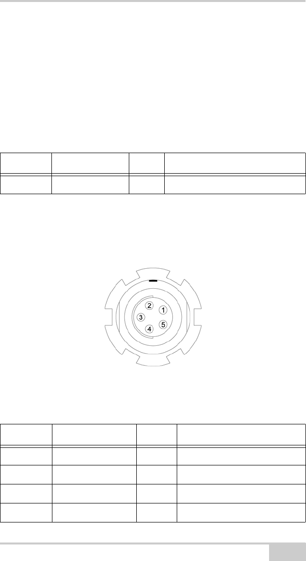
Power Connector
The power connector (Figure A-1) is a sealed receptacle, 5 pin, ODU
part number G80F1C-T05QF00-0000.
Figure A-1. Power Connector
Table A-7 gives power connector specifications.
Table A-6. UHF Modem Connector Specifications
Type Signal Name Dir Details
BNC Modem I/O I/O RF output from modem antenna
Table A-7. Power Connector Specifications
Number Signal Name Dir Details
1 Power_INP P 6 to 28 volts DC input
2 Power_INP P 6 to 28 volts DC input
3 Power_GND P Ground, power return
4 Power_GND P Ground, power return
HiPerXT_om.book Page 11 Monday, April 25, 2005 5:21 PM
Specifications
HiPer XT Operator’s Manual
A-12
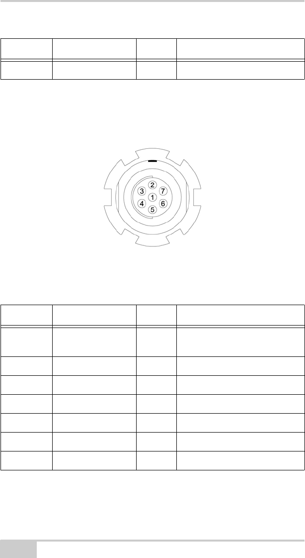
Serial C-RS232 Connector
For ports A and D. The RS232 connectors (Figure A-2) are sealed
receptacle, 7 pin, ODU part number G80F1C-T07QC00-0000.
Figure A-2. RS232 Connector
Table A-8 gives the RS232 cable connector specifications.
5 Not used
Table A-8. RS232 Connector Specifications
Number Signal Name Dir Details
1 Power_OUT P Power Output
(Supplied Voltage)
2 GND - Signal ground
3 CTS I Clear to send
4 RTS O Request to send
5 RXD I Receive data
6 TXD O Transmit data
7 Not used
Table A-7. Power Connector Specifications (Continued)
Number Signal Name Dir Details
HiPerXT_om.book Page 12 Monday, April 25, 2005 5:21 PM
Connector Specifications
P/N 7010-0713 A-13
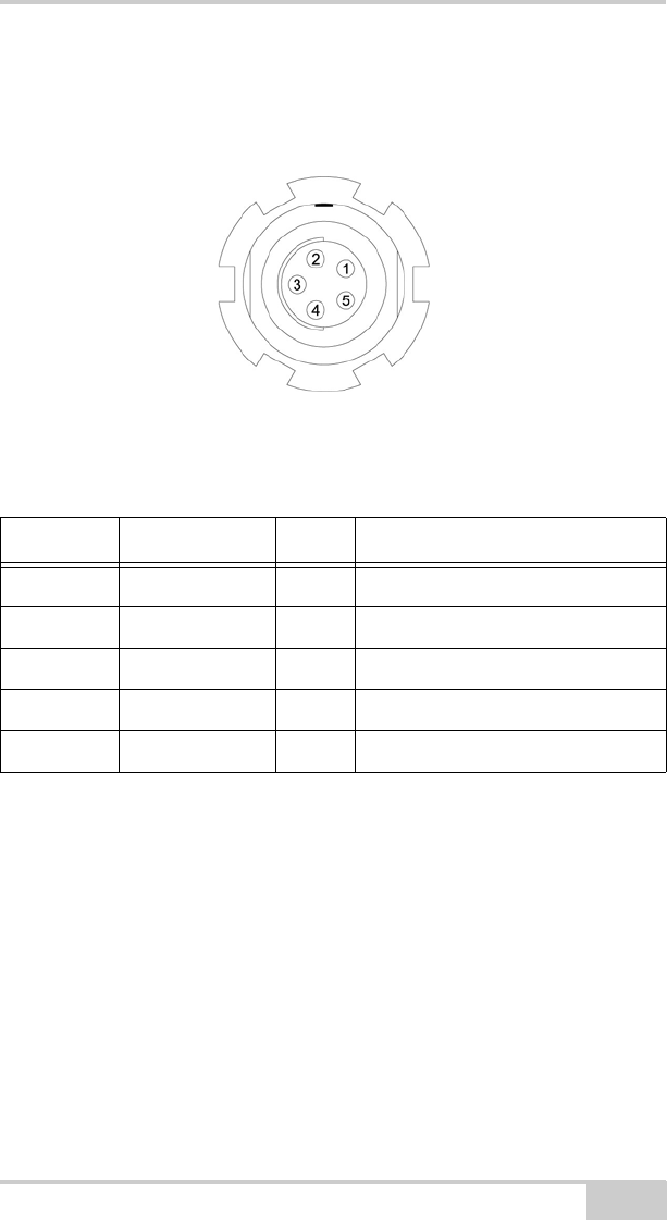
USB Connector
The USB connector is a sealed receptacle, 5 pin TPS cable connector
(Figure A-3).
Figure A-3. USB Connector for GGD Options
Table A-9 gives the USB connector specifications.
Table A-9. USB Specifications
Number Signal Name Dir Details
1 Not used
2 USB_PWR P Bus power input
3 GND - Ground
4 USB D+ I/O Data plus
5 USB D- I/O Data minus
HiPerXT_om.book Page 13 Monday, April 25, 2005 5:21 PM

Specifications
HiPer XT Operator’s Manual
A-14
HiPerXT_om.book Page 14 Monday, April 25, 2005 5:21 PM

P/N 7010-0713
Appendix B
B-1
Safety Warnings
General Warnings
NOTICE
NOTICE
To comply with RF exposure requirements, maintain at
least 25cm between the user and the GSM radio modem.
WARNING
WARNING
TPS receivers are designed for survey and survey
related uses (that is, surveying coordinates, distances,
angles and depths, and recording such
measurements). This product should never be used:
– Without the user thoroughly understanding this
manual.
– After disabling safety systems or altering the
product.
– With unauthorized accessories.
– Without proper safeguards at the survey site.
– Contrary to applicable laws, rules, and regulations.
DANGER
DANGER
TPS RECEIVERS SHOULD NEVER BE USED IN DANGEROUS
ENVIRONMENTS. USE IN RAIN OR SNOW FOR A LIMITED PERIOD
IS PERMITTED.
HiPerXT_om.book Page 1 Monday, April 25, 2005 5:21 PM

Safety Warnings
HiPer XT Operator’s Manual
B-2
Internal Battery Pack
Warnings
DANGER
DANGER
NEVER ATTEMPT TO OPEN THE RECEIVER’S CASING OR
REPLACE THE BATTERIES! LITHIUM-ION BATTERIES CAN BE
DANGEROUS IF MISHANDLED!
DANGER
DANGER
DO NOT INCINERATE OR HEAT BATTERY PACK ABOVE 212
DEGREES FAHRENHEIT (100 DEGREES CELSIUS). EXCESSIVE
HEAT CAN CAUSE SERIOUS DAMAGE AND POSSIBLE
EXPLOSION.
WARNING
WARNING
Tampering with the internal batteries by end users or
non-factory authorized technicians will void the
receiver’s warranty.
– Do not attempt to open the battery pack or replace it.
– Do not disassemble the battery pack.
– Do not charge in conditions different than specified.
– Do not use other than the specified battery charger.
– Do not short circuit.
– Do not crush or modify.
HiPerXT_om.book Page 2 Monday, April 25, 2005 5:21 PM

Usage Warnings
P/N 7010-0713 B-3
Usage Warnings
CAUTION
CAUTION
If this product has been dropped, altered, transported
or shipped without proper packaging, or otherwise
treated without care, erroneous measurements may
occur.
The owner should periodically test this product to
ensure it provides accurate measurements.
Inform TPS immediately if this product does not
function properly.
CAUTION
CAUTION
Only allow authorized TPS warranty service centers to
service or repair this product.
HiPerXT_om.book Page 3 Monday, April 25, 2005 5:21 PM

Safety Warnings
HiPer XT Operator’s Manual
Notes:
B-4
HiPerXT_om.book Page 4 Monday, April 25, 2005 5:21 PM

P/N 7010-0713
Appendix C
C-1
UHF Radio Usage
NOTICE
NOTICE
Many countries require a license for radio users (such as
the United States). Be sure you comply with all local laws
while operating a UHF radio.
Surveying in RTK mode has made UHF the most popular choice for
communications between Base and Rover receivers. Know the
strengths and weaknesses of this technology to get the best use out of
your receiver.
The quality and strength of the UHF signals translates into range for
UHF communications.
1. The system’s range will greatly depend on the local conditions.
Topography, local communications and even meteorological
conditions play a major role in the possible range of RTK
communications.
If needed, use a scanner to find clear channels for
communication.
2. Your system’s range will increase by adjusting the antenna of
your Base station in one of the following ways.
• Ensure the Base radio has a fully charged battery.
• Use directional antennas and/or repeaters to increase your
system’s range. Directional antennas concentrate the signal
power within a more narrow direction, significantly
increasing the range of your system.
• Check out the TPS accessory line for various items to raise
your Base radio.
HiPerXT_om.book Page 1 Monday, April 25, 2005 5:21 PM

UHF Radio Usage
HiPer XT Operator’s Manual
Notes:
C-2
HiPerXT_om.book Page 2 Monday, April 25, 2005 5:21 PM

P/N 7010-0713
Appendix D
D-1
Warranty Terms
TPS laser and electronic positioning equipment are guaranteed
against defective material and workmanship under normal use and
application consistent with this Manual. The equipment is guaranteed
for the period indicated, on the warranty card accompanying the
product, starting from the date that the product is sold to the original
purchaser by TPS’ Authorized Dealers.1
During the warranty period, TPS will, at its option, repair or replace
this product at no additional charge. Repair parts and replacement
products will be furnished on an exchange basis and will be either
reconditioned or new. This limited warranty does not include service
to repair damage to the product resulting from an accident, disaster,
misuses, abuse or modification of the product.
Warranty service may be obtained from an authorized TPS warranty
service dealer. If this product is delivered by mail, purchaser agrees to
insure the product or assume the risk of loss or damage in transit, to
prepay shipping charges to the warranty service location and to use
the original shipping container or equivalent. A letter should
accompany the package furnishing a description of the problem and/
or defect.
The purchaser’s sole remedy shall be replacement as provided above.
In no event shall TPS be liable for any damages or other claim
including any claim for lost profits, lost savings or other incidental or
consequential damages arising out of the use of, or inability to use,
the product.
1. The warranty against defects in Topcon battery, charger, or cable is 90
days.
HiPerXT_om.book Page 1 Monday, April 25, 2005 5:21 PM

Warranty Terms
HiPer XT Operator’s Manual
Notes:
D-2
HiPerXT_om.book Page 2 Monday, April 25, 2005 5:21 PM

P/N 7010-0713
Index
Index
P/N 7010-0713 Index
Index
A
AFRM 2-21, 5-7
Almanac 2-48
and NVRAM 4-17
broadcast data 1-4
collecting 2-48
ephemerides 1-4
update 4-26, 5-3
Always append to file 2-21
Antenna 1-5, 1-10
See also External antenna
See also Internal antenna
cable 1-7
offsets 3-2
radio modem 5-11, 5-12
setup 3-1
internal 3-2
Antenna reference point 3-2
See also ARP
ARP 1-13, 3-2
Automatic file rotation mode 2-21
B
Back panel 1-16
Base station
configuration 3-5–3-7
setup 3-8, 3-9
BATT LED 2-10
blink pattern 2-10, 4-7
green 4-7
orange 4-7
red 4-7
Battery 1-12
charger 1-8, 1-13, 2-4
status 2-10
Baud rate
See Set baud rate
Bluetooth 1-10, 2-11
configuration 2-43
port B settings 2-11, 5-8
security 2-46
unable to connect 2-12
Bluetooth connection parameters 2-13
Bluetooth module file 4-26
BTCONF 2-43
uninstall 2-43
C
Cables 1-7
part numbers 1-7
power supply-to-outlet 1-7
receiver-to-SAE 1-7
RS232 1-7
serial 1-7
Change baud rate 4-4
See also Set baud rate
Charge internal batteries 2-9
Check firmware version 4-20
Checking OAFs 4-14
Clear NVRAM 4-17, 4-26
w/ MINTER 4-18
w/ PC-CDU 4-18
Collecting data 3-4
Components 1-10, 1-13
back panel 1-16
front panel 1-14
Configure
See also Survey configuration
Bluetooth module 2-43
GSM module 1-11
MINTER 2-19
power 2-5
receiver 2-15
HiPerXT_om.book Page 1 Monday, April 25, 2005 5:21 PM

Index
HiPer XT Operator’s Manual
Index
UHF modem 2-27
using PC-CDU 2-15
Connect receiver to computer
unable to connect 2-12
using Bluetooth 2-11
using PC-CDU 2-13
using RS232 cable 2-12, 2-43
using USB cable 2-12
Customer support 5-12
D
Data recording auto-start 2-23
Delete files 4-13–4-14
Differential corrections
LQ field 3-16
Disconnect 2-28
Download
BTCONF 2-43
files 4-10–4-12
firmware 4-21–4-26, 4-26–4-27
FLoader 4-22
indicators 4-12
OAF 4-16
Dual frequency 1-2
E
EIM 4-9–4-10
LED blink indications 4-10
Elevation mask 2-20
External components 1-13
External power 2-3, 2-4
F
File creation mode 2-21
File name prefix 2-16, 2-21
Files
Bluetooth module 4-26
delete 4-13–4-14
download 4-10–4-12
flash 4-23, 4-24, 4-26
power board 4-23, 4-25
RAM 4-23, 4-24, 4-26
select 4-11
Firmware
check version 4-20
files 4-23, 4-26
load 4-21–4-26, 4-26–4-27
Flash file 4-23, 4-24, 4-26
FLoader 1-8, 4-22
FN key 4-3
change baud rate 4-4
data recording 4-3
information modes 4-3
FN key mode 2-23
See also FN key
G
GSM 1-11
phone number 1-11
service plan 1-11
GSM modem
RX LED 4-8
GSM module 1-11
GSM usage 2-27, 2-34, 2-40, 2-41, 3-
5, B-1
I
Information mode
See also Receiver modes
EIM 4-9
extended 4-9
normal 4-9
sleep 4-19
STAT LED 4-9
zero power 4-19
Initial data collection dynamic mode 2-
23
Install
BTCONF 2-43
FLoader 4-22
OAF 4-16
USB driver 2-10
Internal antenna 1-10, 1-13
offset 3-2
setup 3-2
Internal batteries 2-2
HiPerXT_om.book Page 2 Monday, April 25, 2005 5:21 PM

Index
P/N 7010-0713 Index
charge 2-9
status 2-10
Internal components 1-10
K
Kinematic survey 3-8
See also Stop and Go survey
L
LED
BATT 4-7
REC 4-3
RX 4-8
STAT 4-2
Literature 1-9
Load firmware 4-21–4-26, 4-26–4-27
LQ field 3-16
M
Manuals 1-9
online 1-9
Memory 4-17
size of log files 4-17
Minimum INTERface
See MINTER
MINTER 1-14
configuration 2-19
functions 2-18
parameters 2-19, 2-20–2-23
using 4-2
Modem
antenna connector 1-13
Modem configuration 2-25–??
Modem LED
See RX LED
Modem-TPS 1-8, 2-25
disconnect 2-28
uninstall 2-26
version requirements 2-25
N
Normal mode 4-9
NVRAM 1-4, 4-17
clear 4-17, 4-26
w/ MINTER 4-18
w/ PC-CDU 4-18
O
OAF 1-16
check 4-14
load 4-16
Offsets 3-2
horizontal 3-3
internal antenna 3-2
vertical 3-3
Option authorized files
See OAF
P
Package contents
cables 1-7
literature 1-9
power supply/charger 1-8
RTK 1-6
software 1-8
Part number
cables 1-7
power supply/charger 1-8
PC-CDU 1-8, 2-15
configuration 2-15–2-18, 2-19–
2-24
manage power 2-5–2-8
save settings 2-15
Power 2-2
board 1-11
charger 2-4
external 2-3
internal 2-2
management 2-5, 2-5–2-8
Power board file 4-23, 4-25
Power supply/charger 1-8
R
Radio configuration 2-25–??
software 1-8
HiPerXT_om.book Page 3 Monday, April 25, 2005 5:21 PM

Index
HiPer XT Operator’s Manual
Index
RAM file 4-23, 4-24, 4-26
Range C-1
Real-time kinematic 1-2
See also RTK 1-2
REC LED 4-3
green 4-3
orange 4-3
red 4-3, 4-4
Receiver modes 4-18
See also EIM
See also Normal Mode
extended 4-9–4-10
sleep mode 4-19
zero power 4-19
Receiver setup 3-2
Recording interval 2-20
Reset key 4-3
Rover
kinematic setup 3-8–3-9
RTK setup 3-13–3-15
RS232 connection parameters 2-13
RTK 1-2, 3-9
base station setup 3-9
package contents 1-6
rover setup 3-13
RX LED 4-8
and red flashes 5-11, 5-12
blink pattern 4-8
green 4-8
GSM modem 4-8
no light 4-8
orange 4-8
UHF modem 4-8
S
Security parameters 2-46
Serial number 3-6
Set baud rate
115200 2-11, 2-14, 4-22, 5-8
38400 3-12, 3-15
9600 4-4
SHMM 1-15, 1-16, 3-2
Slant height measure mark
See SHMM
Sleep mode 4-19
Software 1-8
FLoader 1-8, 4-21, 4-22
Modem-TPS 1-8
PC-CDU 1-8, 2-15–2-18, 2-19–
2-24
Pinnacle 1-8
radio configuration 1-8
TopSURV 1-9
Start/stop data recording 4-3
STAT LED 4-2, 4-9
blink pattern 4-2, 4-9–4-10
EIM 4-9
green 4-2
orange 4-2
red 4-2
Static survey 3-5–3-7
configuration 3-6
MINTER parameters 3-6
Stop and Go survey 3-8
configuration 3-8
Survey configuration
static 3-6
stop and go 3-8
Surveying
kinematic 3-8
RTK 3-9
static 3-5–3-7
stop and go 3-8
Switch information modes 4-3
System range C-1
T
Test 1-5, 4-9, B-3
EIM 4-9–4-10
TopSURV 1-9
Turn on/off 2-5
U
UHF modem
RX LED 4-8
UHF modem configuration 2-27–??
UHF usage C-1
HiPerXT_om.book Page 4 Monday, April 25, 2005 5:21 PM

Index
P/N 7010-0713 Index
Unable to connect 2-12
Uninstall
BTCONF 2-43
Modem-TPS 2-26
USB connection parameters 2-14
USB driver 2-10
W
Warnings B-1
battery pack B-2
general B-1
usage B-3
Z
Zero power mode 4-19
reset key 4-3
HiPerXT_om.book Page 5 Monday, April 25, 2005 5:21 PM

HiPer XT Operator’s Manual
Notes:
Index
HiPerXT_om.book Page 6 Monday, April 25, 2005 5:21 PM

Notes
Notes:
HiPerXT_om.book Page 1 Monday, April 25, 2005 5:21 PM

Notes
Notes:
HiPerXT_om.book Page 2 Monday, April 25, 2005 5:21 PM