Tornado 9SYLTX2-1 Radio Control of Models at Amusement Arcades User Manual Installation Manual
Tornado International Limited Radio Control of Models at Amusement Arcades Installation Manual
Tornado >
Contents
- 1. User Manual
- 2. Installation Manual
Installation Manual
1N00-511 Genesis 80cm Boat Installation Manual - Export v1.0 08/03
©Tornado International Ltd. 2003 -1- Confidential
Genesis
80cm Boat
1N00-511 Installation Manual

1N00-511 Genesis 80cm Boat Installation Manual - Export v1.0 08/03
©Tornado International Ltd. 2003 -2- Confidential
Company Information.
Telephone Fax
Technical Help +44(0)121-773-1827 (0)121-772-6056 Ask for
Technical
Help
Parts & Accessories +44(0)121-773-1827 (0)121-772-6056 Ask for the
Parts Dept
Unit Sales +44(0)121-773-1827 (0)121-772-6056 Katie
Roberts
Comments: +44(0)121-773-1827 Stuart Bland
Addresses:
Head Office, Sales Office & Production
Tornado International Ltd
Unit 28 Green Lane Industrial Estate
Second Avenue
Birmingham
B9 5QP
England
Tel: +44(0)121-773-1827
Fax: +44(0)121-772-6056
A Member of the Tornado International Leisure Group
1N00-511 Genesis 80cm Boat Installation Manual - Export v1.0 08/03
©Tornado International Ltd. 2003 -3- Confidential
Conventions used in this Manual
For clarity the following conventions are used in this manual:
Paragraph Heading
Meaning
Tip!
Information which will assist in the operation
of the product
Note!
Information which is important for the correct
operation of the product.
Caution!
Information which is
VITAL
to avoid injury to
persons or damage to the product.
Warning!
Information which is
VITAL
to avoid serious
injury to personnel or the public.
Please take note of the information in shaded areas. If you have any
questions with regard to the correct installation or operation of the product
please contact Tornado International Ltd.
Important – Please Read This!
This manual is provided in good faith and is believed to be accurate. Because
Tornado International have no control over the manner in which the product is
used, users should satisfy themselves that any information or instruction
contained in this manual is appropriate for the conditions under which the
product is being installed and operated.
In the interest of product development, Tornado International reserves the
right to alter or modify the product as necessary.

1N00-511 Genesis 80cm Boat Installation Manual - Export v1.0 08/03
©Tornado International Ltd. 2003 -4- Confidential
On Delivery
Before Opening Crates
1. Check the number of crates delivered agrees with the number on the
shipping documents.
2. Inspect the crates for damage. If any damage is visible note the crate
number, and the position and extent of the damage. If the crates are not to
be opened immediately, the shipping company should be notified as soon
as possible. If the crates are to be opened at this time, wait until the
product is inspected for damage.
3. The crates should be moved to a position close to the operating area
before opening.
4. The crates should be opened carefully, the contents removed and the
quantities checked against the shipping notes. A product identification
chart can be found at Appendix A. If any damage was noted on the outside
of the crates, the product next to the damage should be inspected
carefully. Any damage should be notified to the shipping company as soon
as the product is unpacked. Any shortage should be notified to Tornado
International Ltd. in writing (letter, fax or e-mail) as soon as possible and in
any event not later than 5 days after receipt.

1N00-511 Genesis 80cm Boat Installation Manual - Export v1.0 08/03
©Tornado International Ltd. 2003 -5- Confidential
Before Installation
All equipment (except UK) designed to operate off mains voltage supply (100v
to 240v) is supplied without a connecting plug. Ensure that the required
number of plugs are available before starting the installation.
Caution!
Check that the supply voltage matches the voltage setting on the front of the
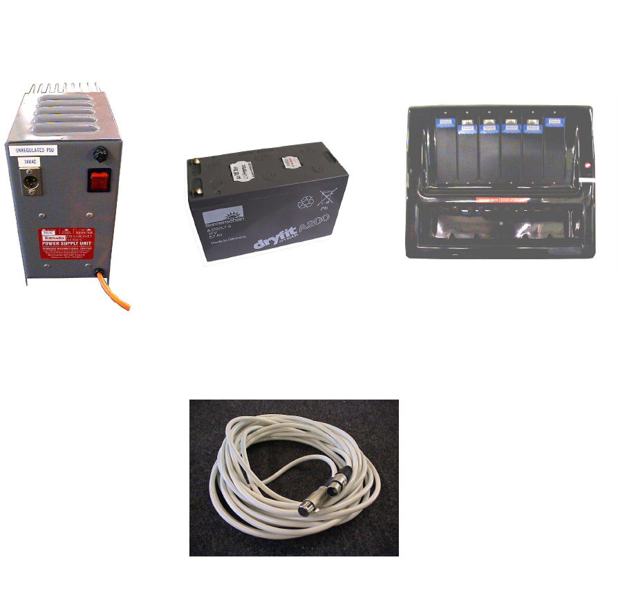
PSU and Charger cases. (Dia. 5 & 6)
Tools & Items Required: (These are not supplied with the unit)
Small flat screwdriver
Medium flat screwdriver
Medium cross point screwdriver
Power drill
8mm drill bit
51mm hole cutter
10mm socket and ratchet
¼ whitworth socket (or adjustable spanner)
Soldering Iron
Staple Gun or 3mm cable clips
7mm cable clips
10off each coin/token used
Setting Out the Equipment:
1. Before starting the installation place the consoles on the floor in the
position they are to be mounted. The consoles may be mounted either
indoors or outside. Console number “1” should be on the left with the
consoles running in numerical order to the right.
2. Place the Power Supply Unit (PSU) in the position it will be used. The rear
of the PSU has a large aluminium heat sink. It is important that the PSU is
positioned so that there is an uninterrupted flow of cool air over the heat
sink.
Caution!
The PSU must be mounted indoors and in such a position that the public
do not have access to it. It must be protected from water.
3. Place the chargers in the position they will be used. The top and bottom of
the charger case has vents to provide cooling. It is important that the
chargers are positioned so that there is an uninterrupted flow of cool air
over the vents. Caution!
The chargers must be mounted indoors and in such a position that the
public do not have access to them. They must be protected from water.
4. Check that the PSU and charger mains cables will reach the electric
supply sockets.
5. Lay out the 24V PSU cable and check that it is long enough to reach from
the master console to the PSU.

1N00-511 Genesis 80cm Boat Installation Manual - Export v1.0 08/03
©Tornado International Ltd. 2003 -6- Confidential
Note!
The PSU cable must not be lengthened without consulting Tornado
International Ltd.
Tip!
The master console can be identified by an additional door to the right of
the coin acceptor door. It is usually number 4 or 6. It is the console with
the transmitter inside.
6. If you have more than one console open the console door (the key is in the
spares pack) and locate the console cable coiled up inside. Check that the
cables from all additional consoles reach the console connection sockets
inside the master console.
When you have satisfied yourself that all of the units are suitably positioned
the installation can begin.
1N00-511 Genesis 80cm Boat Installation Manual - Export v1.0 08/03
©Tornado International Ltd. 2003 -7- Confidential
The Installation
The Consoles:
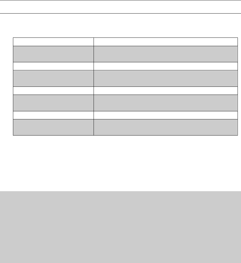
The consoles are usually mounted on a fence or low wall. The lip (See Dia. 3)
at the top of the console serves to locate the console on the top of the wall or
fence and assists in the mounting process. The lip may be removed if required
by marking a line along the top of the console and cutting along the line with a
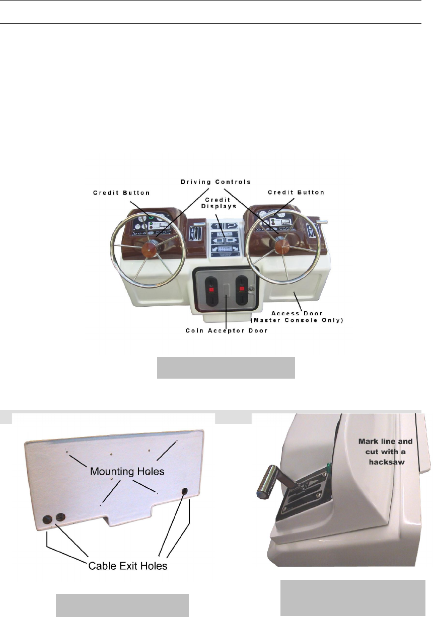
hacksaw. There are 4 mounting holes in the back of the console and large
cable holes on the back and underside of the console to route the console
connection cables. (See Dia. 2)
Dia. 1 – Console
Dia. 2 – Console
Rear
Dia. 3 – To Remove Lip
(If required)
1N00-511 Genesis 80cm Boat Installation Manual - Export v1.0 08/03
©Tornado International Ltd. 2003 -8- Confidential
Caution!
Whenever possible use the predrilled mounting holes in the rear of the
console (See Dia. 2). If this is not possible, alternative holes may be drilled in
the back of the console only after checking that there are no items or
electronics inside the console, in the area to be drilled. Any damage caused
by not following this instruction is the responsibility of the installer.
1. With the coin acceptor door open the console should be placed in the
chosen position on the wall or fence to which it is to be fixed.
2. The position of the mounting holes (and cable holes if required) should be
marked on the wall or fence using a scribe or pencil from inside the
console.
3. The console can then be removed and using an 8mm drill bit, the four
mounting holes can be drilled in the wall or fence. Any required cable
holes can then be drilled in the wall or fence,
using a 51mm hole saw.
4. Locate the console mounting bolts and position
the bolts with one washer under the head through
the wall or fence from the model operating side.
5. Prepare four washers and wing nuts. With a
helper holding the bolts in place, lift the console
into position and locate it onto the mounting bolts.
Fit a washer and wing nut to each bolt and
tighten securely.
6. Repeat for each console.
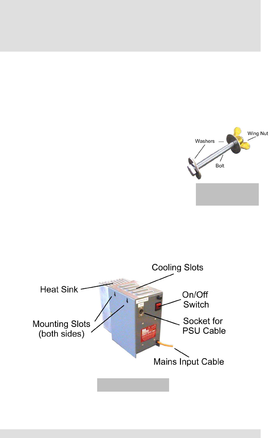
The Power Supply Unit:
The PSU (See Dia. 5) can either be stood on a shelf or hung on a wall using
the slots in the sides of the case. The rear of the PSU has a large aluminium
heat sink. It is important that the PSU is positioned so that there is an
uninterrupted flow of cool air over the heat sink.
Caution!
Dia. 4 - Console
Mounting Bolt
Dia. 5 – The PSU
1N00-511 Genesis 80cm Boat Installation Manual - Export v1.0 08/03
©Tornado International Ltd. 2003 -9- Confidential
The PSU must be mounted indoors and in such a position that the public do
not have access to it. It must be protected from water.
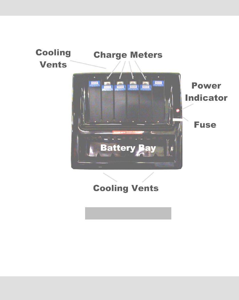
The Chargers:
The chargers (See Dia. 6) must be mounted on a wall using the slots in the
rear of the case. The top and bottom of the charger case has vents to provide
cooling. It is important that the chargers are positioned so that there is an
uninterrupted flow of cool air over the vents.
Caution!
The chargers must be mounted indoors and in such a position that the public
do not have access to them. They must be protected from water.
The chargers should now be connected to the electric supply. The batteries
are fully charged when the unit is dispatched from the factory, however if the
unit has been in transit for some time it might be prudent to charge the
batteries whilst the rest of the installation is carried out. See the section “The
Battery Chargers” in the operation manual for how to charge the batteries.
Dia. 6 – The Charger
1N00-511 Genesis 80cm Boat Installation Manual - Export v1.0 08/03
©Tornado International Ltd. 2003 -10- Confidential
Routing the Console Cables:
Each console has a grey cable coiled inside the console on the side nearest
the master console. Each of these has to be routed out of the console and into
the master console. The cables should be supported using 8mm cable clips
every 30cm.
1. Open the coin acceptor door and locate the console cable.
2. Uncoil the cable and feed the plug out of the console using one of the
large holes in the back or bottom as required.
3. Route the cable to the master console and fit the plug into the correct
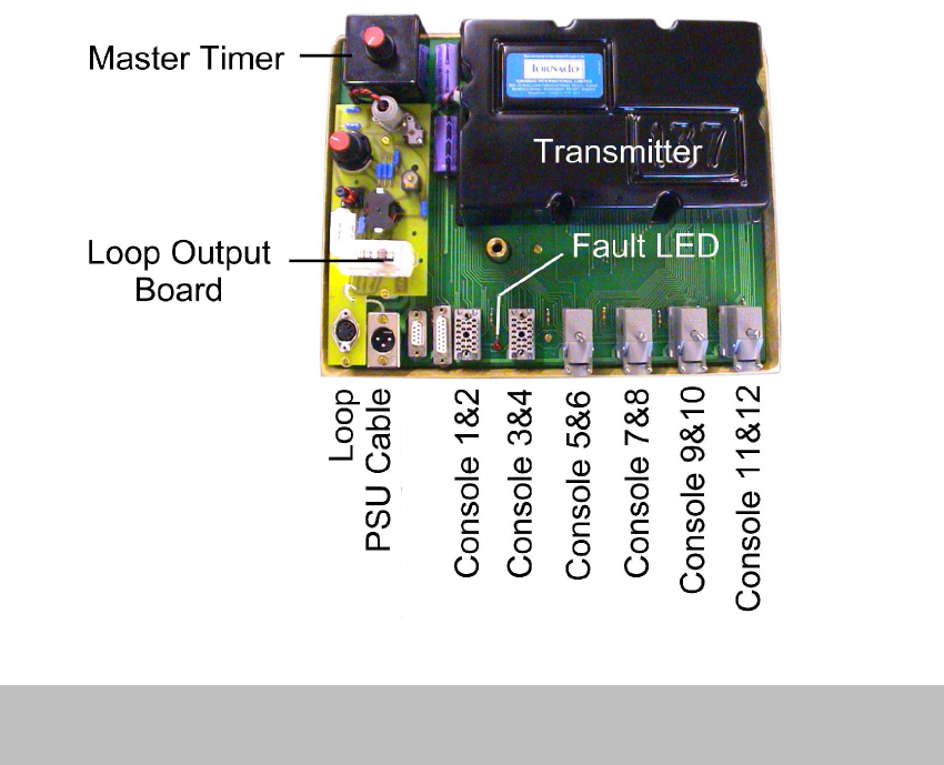
numbered socket on the transmitter motherboard (See Dia. 7) (The socket
numbers are on the transmitter motherboard cover). Do not fix the cables
in position at this time.
4. Repeat the routing for all console cables. It should be noted that the cable
for the master console is fitted at the factory. All of the console cables are
the same length so some surplus will remain for consoles close to the
master console.
5. Leaving a small loop of cable in the master console, fix the cables in
position starting at the master console and working toward the standard
console(s).
6. Coil up any excess cable and place it inside the standard console to one
side, ensuring that the coil of cable does not interfere with the operation of
any of the console controls.
Dia. 7 – The Transmitter Mother Board showing the Master Console Connection Sockets
(Inside the access door of the master console)

1N00-511 Genesis 80cm Boat Installation Manual - Export v1.0 08/03
©Tornado International Ltd. 2003 -11- Confidential
7. Repeat the cable fixing for any other consoles.
Note!
When you have finished connecting all of the supplied consoles check to
ensure all of the master console connection sockets have either a console
connected or a dummy plug installed.
Routing the PSU cable:
The PSU cable has to be routed from the master console to the PSU. This
cable carries the 24v ac produced by the PSU to the consoles.
Note!
The PSU cable must not be lengthened without consulting Tornado
International Ltd.
1. Plug the PSU cable into the 24v socket in the master console. (See Dia. 7)
2. Route the cable from the master console to the PSU.
3. Starting at the master console fix the cable in place using 8mm cable clips.
4. Coil any excess cable next to the PSU.
5. Plug the PSU mains supply input cable into an outlet of the correct voltage
(See Dia. 5).
6. Check that the PSU is turned off. (The neon indicator is off.)
7. Connect the cable to the PSU.
Do not turn on the PSU at this time.
The Loop:
The loop is the aerial used by the transmitter (TX) to send the control signal to
the models. We use a loop type aerial because it concentrates the available
transmitter power into the operating area for better interference rejection. The
loop wire will be found with the spares pack. If required any wire of at least the
same cross sectional area can be used. The loop forms a complete loop
starting at the loop plug in the master console (See Dia. 7), running around
the perimeter of the model operating area and ending back at the loop plug in
the master console (See Dia. 8).
1N00-511 Genesis 80cm Boat Installation Manual - Export v1.0 08/03
©Tornado International Ltd. 2003 -12- Confidential
1. Locate the loop wire and leaving 3M excess, attach the wire to the model
retaining wall at a convenient point below the master console. The loop
wire may be run on the outside of the retaining wall or on the inside.
2. Fix the wire around the operating area using staples or cable clips every
300mm. Choose a position and height that does not cause the models to
rub against the wire, and is not easily seen by the public.
3. The wire should be run around the area to finish at the point you started.
Leave 3M and cut the wire. The remaining wire
should be retained for any future use.
4. Route the two lengths of wire to the loop socket in
the master console and cut them to a convenient
length so that they reach the socket (See Dia. 7).
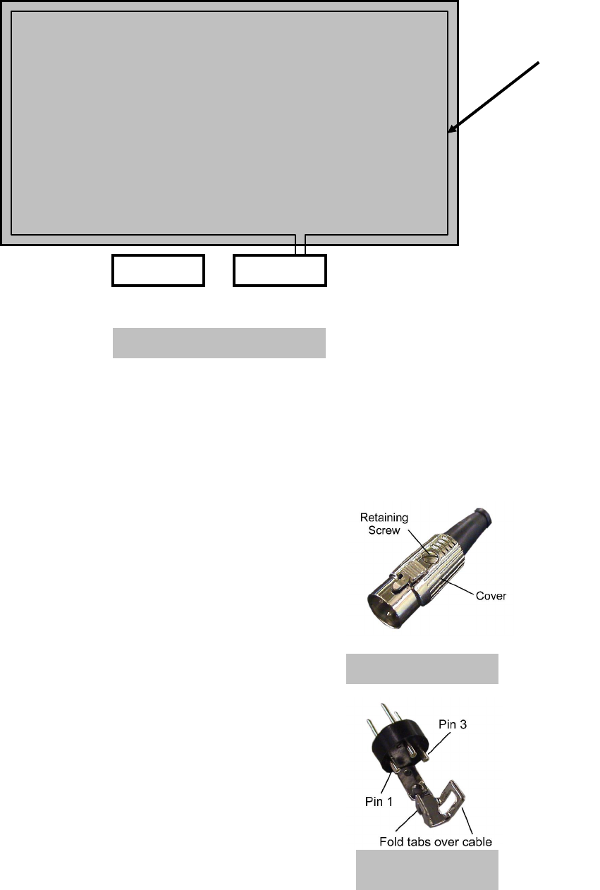
5. Locate the loop plug in the spares pack (2 are
supplied), remove the retaining screw and cover
(See Dia. 9).
6. Slide the cover over the two wires, strip 5mm of the
outer covering from each wire and solder one to pin
number 1 and the other to pin number 3. It does not
matter which wire goes to which pin (See Dia. 10).
7. Ensure that there are no stray strands of wire to
short across the pins and that the solder joints are
good.
8. Re-assemble the cover onto the plug and refit the
screw.
9. Fit the loop plug into the loop socket in the master
console (See Dia. 7).
Model Operating Area
Master Console
Loop Aerial
Dia. 8 – The Loop Aerial
Dia. 9 – Loop Plug
Dia. 10 – Inside the
Loop Plug
1N00-511 Genesis 80cm Boat Installation Manual - Export v1.0 08/03
©Tornado International Ltd. 2003 -13- Confidential
The Models:
The models should be handled with care. They are designed to be as robust
as possible within the constraints of their size.
1. Carefully unpack the models and place them near their driving positions.
Tip! Use spare packing material to protect the underside of the hulls.
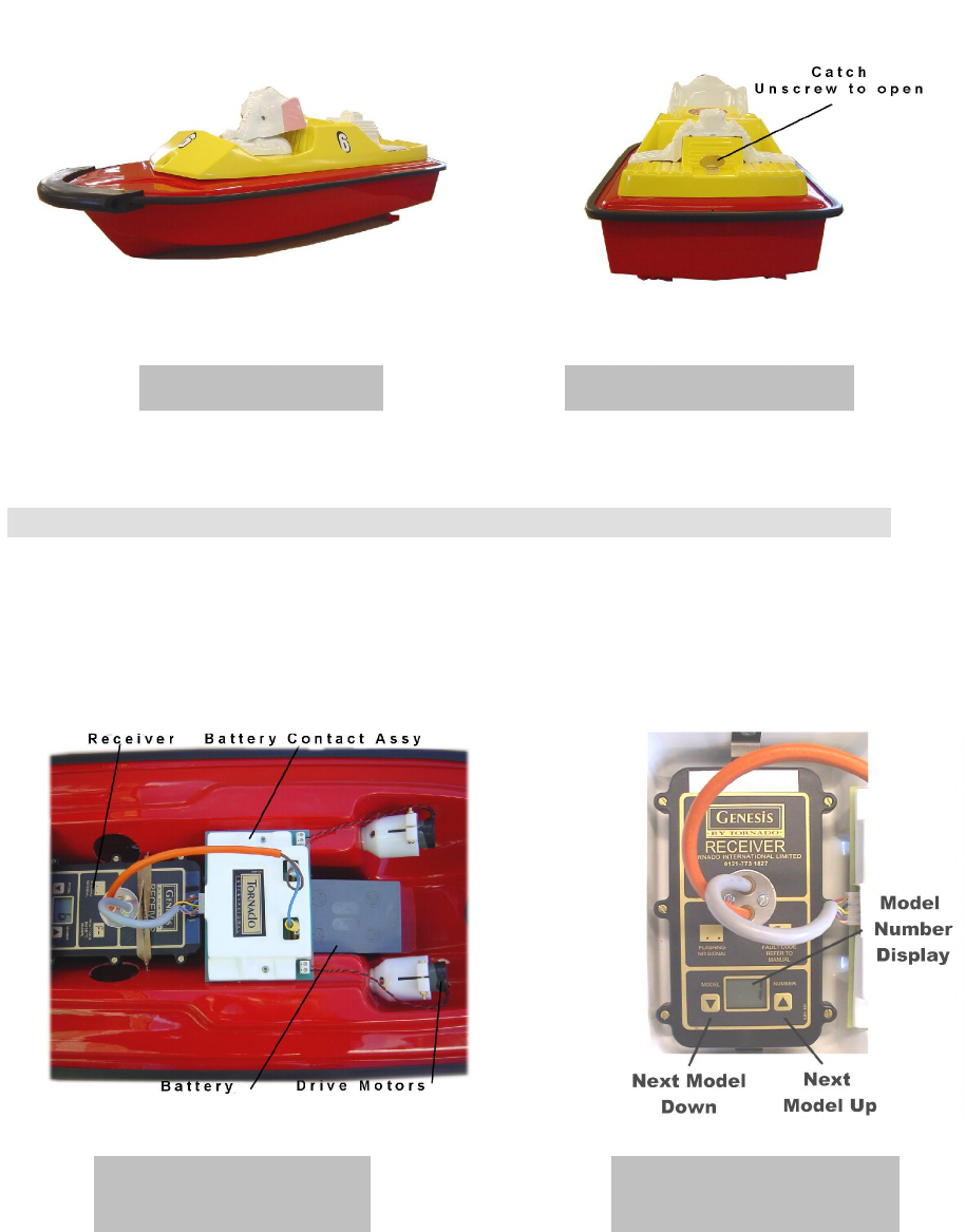
2. Remove the top of the model by rotating the catch, then gently slide the
top forward to release the front catch (See Dia. 12).
Do not connect the battery to the model at this time.
Dia. 11 – The Model Dia. 12 – The Top Catch
Dia. 13 – The Model
Interior
Dia. 14 – The Receiver in
Position in the Boat
1N00-511 Genesis 80cm Boat Installation Manual - Export v1.0 08/03
©Tornado International Ltd. 2003 -14- Confidential
Power Up & Testing
All of the stages described in “The Installation” should be completed before
these instructions are followed. The power to the unit will be turned on and the
primary functions of the unit will be tested manually. This will allow the unit to
be entered into service. The test procedures will duplicate some of the tests
carried out at the factory prior to shipment. All aspects of every unit’s
operation are tested as the last stage of production. If you encounter any
problems please check to ensure you have carried out the installation
correctly. If you still have a problem please make a note of the exact nature of
the fault, all of the symptoms and the serial number of the unit. Then
telephone the Tornado International Ltd technical helpline.
Power Up & Testing:
1. Turn on the PSU (See Dia. 5).
Before the manual test can begin the loop aerial will have to be tuned. Follow
the instructions in the following section “Tuning the Loop”.
Tuning the Loop:
For a transmitter (TX) to work correctly the aerial needs to be a specific
length, which depends on the frequency used for transmission. As the
transmission frequency is fixed but the length of the aerial (loop) varies
depending on the perimeter of the operating area, we have to provide a
system to “match” the length of the loop to the transmitter. The device to
achieve this is called the “Loop Output Board” and is housed to the left of the
transmitter in the master console (See Dia. 7 & 15). The operation of adjusting
the Loop Output Board to achieve an aerial match is called “Tuning the Loop”
Caution!
Failure to tune the loop correctly will lead to
overheating of the receivers in the models and
may lead to failure of the transmitter. These
items are of high value and any failures caused
by not following these instructions are the
responsibility of the installer.
The following instructions are important. Please
read and thoroughly understand them before
proceeding. If you are at all unsure then
telephone the Tornado International Ltd technical
help line.
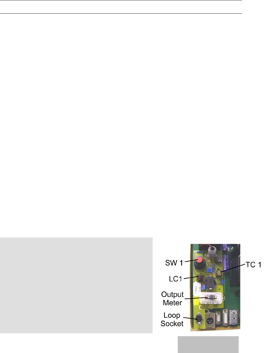
1. Remove the cover from the transmitter
motherboard.
2. Locate the adjusters SW1 & TC1 (Dia. 15).
3. Check that the loop plug is securely connected to the loop socket.
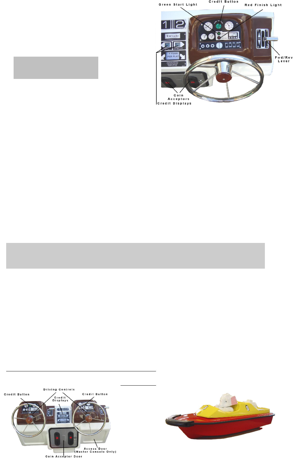
4. Check that every playing position has a red light showing and that each
credit display is showing “0” (See Dia. 16).
Dia. 15
Loop Output Board

1N00-511 Genesis 80cm Boat Installation Manual - Export v1.0 08/03
©Tornado International Ltd. 2003 -15- Confidential
5. Check that the fault LED in the master console (See Dia. 7) is not on. If it
is, check to ensure that every console socket has a plug connected.
6. Rotate SW1 fully anti-clockwise and observing the loop output meter select
each clockwise position in turn, noting the loop output meter reading at
each position.
Note: If the loop output meter should read over 10 during this procedure
adjust LC1 to return the needle to 5. Please read the note and instructions
below before doing this.
7. Select the position of SW1 corresponding to the highest reading and note
that reading.
8. Using a screwdriver, rotate TC1 through 3600 and note the action of the
loop meter. If when rotating TC1 through one complete revolution, the loop
meter does not raise above the reading obtained at stage 6, rotate SW1
one position anti-clockwise and again continue from step 8.
9. When rotating TC1 through one complete revolution the loop meter should
show 2 positions when the meter is at its highest.
10. Rotate TC1 to obtain the highest reading on the loop meter.
11. To check if the loop is tuned correctly move TC1 a quarter of a turn in each
direction. The loop meter reading should fall in both cases. Re-adjust TC1
to give the highest reading.
The next operation is carried out to adjust the loop output meter to read 8.
This is to provide a datum reading for any future evaluation of transmitter
performance.
Note!
It should be understood that although the reading of the loop output meter is
being adjusted during this operation, the actual output of the transmitter and
the loop tuning is not being affected in any way. The only thing that is being
changed is the coupling of the output meter to the transmitter.
It is important that this is understood and that this operation is only carried out
during installation or replacement/re-siting of the loop. The core of LC1 is
made of carbon. It is very brittle so adjust it with care.
1. Locate LC1 (See Dia. 15).
2. Using a small screwdriver carefully rotate LC1 to adjust the loop meter to
give a reading of 8.
1N00-511 Genesis 80cm Boat Installation Manual - Export v1.0 08/03
©Tornado International Ltd. 2003 -16- Confidential
Continuation of Installation Test:
1. Check that the red finish lights on all of the consoles are turned on (See
Dia. 16).
2. Turn the playtime control on the master timer to maximum (fully clockwise)
(See Dia. 7).
3. Open all of the cash doors.
4. Observing the credit displays introduce enough coins/tokens to purchase
one play. The credit display should show “1” and the green credit button
should flash. Repeat for each playing position.
5. Press the green credit button, the credit display should now show “0” the
credit button stops flashing and turns on, the red finish light should turn to
green. Repeat for each playing position.
6. At the end of the set time a sounder will be heard and the green play light
will return to red.
7. Insert a battery into each model. (See Dia. 13)
Caution!
Lift the rear of the model as the battery is slid into position to allow the
propellers to rotate.
8. Again introduce enough coins/tokens to purchase one play into playing
position “1”. The credit display should show “1” and the green credit button
should flash. Press the green credit button to trigger the game. Check that
the red finish light has turned to green.
9. Place model number 1 on the water. Move the forward/reverse stick to
forward. The model should move forward. Turn left and right to check that
the model responds correctly. Repeat for reverse. At the end of the play
period the green play light will turn to red and control will be removed from
the playing position.
10. Repeat the test for each model.
The unit is now ready for use.
Appendix A
Dia. 16 – The Playing
Position
1N00-511 Genesis 80cm Boat Installation Manual - Export v1.0 08/03
©Tornado International Ltd. 2003 -17- Confidential
Console
Model
PSU Cable
PSU Battery
Battery
Charger
(Style of tops may vary)