Toro 5010 H Rm5010h 0 User Manual To The 86212508 B1f8 4e00 8800 Fde94b2fc51b
User Manual: Toro 5010-H to the manual
Open the PDF directly: View PDF ![]() .
.
Page Count: 335 [warning: Documents this large are best viewed by clicking the View PDF Link!]
- Preface
- Table Of Contents
- Table Of Contents (Continued)
- 1 - Safety
- 2 - Product Records and Maintenance
- 3 - Kubota Diesel Engine
- Kubota Workshop Manual, 05-E4B Series
- 4 - Hydraulic System
- Table of Contents
- Specifications
- General Information
- Hydraulic Schematic
- Hydraulic Flow Diagrams
- Special Tools
- Troubleshooting
- Testing
- Traction Circuit Relief Valve (R3) and (R4) Pressure Test
- Traction Circuit Charge Pressure Test
- Gear Pump (P2) Flow Test
- Front Wheel Motor Efficiency Test
- Piston (Traction) Pump Flow Test
- Lift Relief Valve (SVRV) Pressure Test
- Gear Pump (P1) Flow Test
- Lift Cylinder Internal Leakage Test
- Steering Relief Valve (R10) Pressure Test
- Steering Cylinder Internal Leakage Test
- Service and Repairs
- General Precautions for Removing and Installing Hydraulic System Components
- Check Hydraulic Lines and Hoses
- Flush Hydraulic System
- Filtering Closed- Loop Traction Circuit
- Hydraulic System Start- up
- Hydraulic Reservoir
- Piston (Traction) Pump Control Assembly
- Hydraulic Pump Assembly
- Piston (Traction) Pump Service
- Gear Pump Service
- Hydraulic Pump Drive Shaft
- Hydraulic Pump Drive Shaft Cross and Bearing Service
- Front Wheel Motors
- Front Wheel Motor Service
- Rear Wheel Motors (Machines with Optional CrossTrax Kit)
- Rear Wheel Motor Service (Machines with Optional CrossTrax Kit)
- Control Manifold Cartridge Valve Service
- Lift Control Manifold
- Lift Control Manifold Service
- CrossTrax AWD Manifold
- CrossTrax AWD Manifold Service
- Lift Cylinders
- Lift Cylinder Service
- Steering Control Valve
- Steering Control Valve Service
- Steering Cylinder
- Steering Cylinder Service
- Hydraulic Oil Cooler
- Sauer-Danfoss LPV Closed Circuit Axial Piston Pumps Repair Manual
- Sauer-Danfoss LPV Closed Circuit Axial Piston Pumps Service Instructions
- Eaton Delta Motors Parts and Repair Manual
- Parker Torqmotor Service Procedure (TC, TB, TE, TJ, TF, TG, TH, and TL Series)
- Sauer-Danfoss Steering Unit Type OSPM Service Manual
- 5 - Electrical System
- Table of Contents
- General Information
- Electrical System Operation
- Special Tools
- InfoCenter Display
- Troubleshooting
- Electrical System Quick Checks
- Adjustments
- Component Testing
- Ignition Switch
- 12 VDC System Fuses
- 48 VDC System Fuses
- Engine Speed Switch
- Reel Engage/Disengage Switch
- Headlight Switch
- Seat Switch
- Parking Brake Switch
- Traction Neutral Switch
- Cutting Unit Down Limit Switch
- Joystick Raise and Lower Switches
- Mow/Transport Switch
- Main Power, Glow and 48 VDC Logic Relays
- Start Relay
- Main Contactor
- Toro Electronic Controller (TEC)
- Fusible Link Harness
- Diode Assembly
- 48 VDC System Protection Diode
- Location ID Module
- Cutting Reel Motor
- CAN- bus Termination Resistors
- Hydraulic Solenoid Valve Coil
- Temperature Sender
- Oil Pressure Switch
- Fuel Actuator
- Fuel Sender
- Fuel Pump
- Service and Repairs
- 6 - Chassis
- 7 - Cutting Units
- Table of Contents
- Specifications
- General Information
- Special Tools
- Factors That Can Affect Cutting Performance
- Set Up and Adjustments
- Service and Repairs
- Cutting Reel Motor
- Backlapping
- Bedbar Assembly
- Bedknife Replacement and Grinding
- Bedbar Adjuster Service
- Cutting Reel Assembly Removal and Installation
- Cutting Reel Assembly Service
- Preparing Reel for Grinding
- Front Roller
- Rear Roller
- Roller Service
- Rear Roller Brush (Optional)
- Rear Roller Brush Drive System (Optional)
- 8 - Groomer
- 9 - Foldout Drawings
Part No. 15212SL
Service Manual
ReelmasterR5010- H
Preface
The purpose of this publication is to provide the service
technician with information for troubleshooting, testing
and repair of major systems and components on the
Reelmaster 5010- H (Hybrid).
REFER TO THE TRACTION UNIT AND CUTTING
UNIT OPERATOR’S MANUALS FOR OPERATING,
MAINTENANCE AND ADJUSTMENT INSTRUC-
TIONS. Space is provided in Chapter 2 of this book to
insert the Operator’s Manuals and Parts Catalogs for
your machine. Additional copies of the Operator’s
Manual and Parts Catalog are available on the internet
at www.Toro.com.
The Toro Company reserves the right to change product
specifications or this publication without notice.
This safety symbol means DANGER, WARNING,
or CAUTION, PERSONAL SAFETY INSTRUC-
TION. When you see this symbol, carefully read
the instructions that follow. Failure to obey the
instructions may result in personal injury.
NOTE: ANOTE will give general information about the
correct operation, maintenance, service, testing or re-
pair of the machine.
IMPORTANT: The IMPORTANT notice will give im-
portant instructions which must be followed to pre-
vent damage to systems or components on the
machine.
EThe Toro Company - 2015
Reelmaster 5010- H
This page is intentionally blank.

Reelmaster 5010- H
Table Of Contents
Chapter 1 - Safety
Safety Instructions 1 - 2..........................
Jacking Instructions 1 - 5.........................
Safety and Instruction Decals 1 - 6................
Chapter 2 - Product Records and Maintenance
Product Records 2 - 1...........................
Maintenance 2 - 1...............................
Equivalents and Conversions 2 - 2................
Torque Specifications 2 - 3.......................
Chapter 3 - Kubota Diesel Engine
Specifications 3 - 2..............................
General Information 3 - 3........................
Service and Repairs 3 - 4........................
KUBOTA WORKSHOP MANUAL, DIESEL ENGINE,
05- E4B SERIES
Chapter 4 - Hydraulic System
Specifications 4 - 2..............................
General Information 4 - 3........................
Hydraulic Schematic 4 - 10.......................
Hydraulic Flow Diagrams 4 - 12...................
Special Tools 4 - 20.............................
Troubleshooting 4 - 25...........................
Testing 4 - 30...................................
Service and Repairs 4 - 52.......................
SAUER- DANFOSS LPV CLOSED CIRCUIT AXIAL
PISTON PUMPS REPAIR MANUAL
SAUER- DANFOSS LPV CLOSED CIRCUIT AXIAL
PISTON PUMPS SERVICE INSTRUCTIONS
EATON DELTA MOTORS PARTS AND REPAIR
MANUAL
PARKER TORQMOTORTM SERVICE PROCEDURE
(TC, TB, TE, TJ, TF, TG, TH AND TL SERIES)
SAUER- DANFOSS STEERING UNIT TYPE OSPM
SERVICE MANUAL
Chapter 5 - Electrical System
General Information 5 - 2........................
Electrical System Operation 5 - 4.................
Special Tools 5 - 6..............................
InfoCenter Display 5 - 10.........................
Troubleshooting 5 - 18...........................
Electrical System Quick Checks 5 - 40.............
Adjustments 5 - 42..............................
Component Testing 5 - 46........................
Service and Repairs 5 - 77.......................
Chapter 6 - Chassis
Specifications 6 - 2..............................
General Information 6 - 2........................
Special Tools 6 - 3..............................
Service and Repairs 6 - 4........................
Chapter 7 - Cutting Units
Specifications 7 - 2..............................
General Information 7 - 3........................
Special Tools 7 - 4..............................
Factors That Can Affect Cutting Performance 7 - 8..
Set- Up and Adjustments 7 - 12...................
Service and Repairs 7 - 14.......................
SafetyProduct Records
and Maintenance
Cutting Electrical
System
Hydraulic
System Kubota Diesel
Engine
Chassis
Units
Reelmaster 5010- H
This page is intentionally blank.

Reelmaster 5010- H
Table Of Contents (Continued)
Chapter 8 - Groomer
General Information 8 - 2........................
Special Tools 8 - 3..............................
Grooming Performance 8 - 4.....................
Troubleshooting 8 - 5............................
Adjustments 8 - 7...............................
Service and Repairs 8 - 8........................
Chapter 9 - Foldout Drawings
Electrical Drawing Designations 9 - 2..............
Hydraulic Schematic 9 - 3........................
Electrical Schematic 9 - 4........................
Wire Harness Drawings 9 - 6.....................
GroomerFoldout
Drawings
Reelmaster 5010- H
This page is intentionally blank.

Reelmaster 5010- H Page 1 - 1 Safety
Chapter 1
Safety
Table of Contents
SAFETY INSTRUCTIONS 2......................
Before Operating 2............................
While Operating 3.............................
Maintenance and Service 4....................
JACKING INSTRUCTIONS 5.....................
SAFETY AND INSTRUCTION DECALS 6..........
Safety

Reelmaster 5010- HPage 1 - 2Safety
Safety Instructions
Reelmaster machines meet or exceed safety standard
specifications when weights are installed according to
information in the Traction Unit Operator’s Manual. Al-
though hazard control and accident prevention are par-
tially dependent upon the design and configuration of
the machine, these factors are also dependent upon the
awareness, concern and proper training of the person-
nel involved in the operation, transport, maintenance
and storage of the machine. Improper use or mainte-
nance of the machine can result in injury or death. To re-
duce the potential for injury or death, comply with the
following safety instructions.
To reduce the potential for injury or death, com-
ply with the following safety instructions.
WARNING
Before Operating
1. Review and understand the contents of the Opera-
tor’s Manuals and Operator Training DVD before start-
ing and operating the machine. Become familiar with the
controls and know how to stop the machine and engine
quickly. Additional copies of the Operator’s Manual are
available on the internet at www.Toro.com.
2. Keep all shields, safety devices and decals in place.
If a shield, safety device or decal is defective, illegible
or damaged, repair or replace it before operating the
machine. Also tighten any loose nuts, bolts or screws to
ensure machine is in safe operating condition.
3. Assure interlock switches are adjusted correctly so
engine cannot be started unless traction pedal is in
NEUTRAL and Enable/Disable switch is OFF (dis-
abled).
4. Since fuel is flammable, handle it carefully:
A. Store fuel in containers specifically designed for
this purpose.
B. Do not remove machine fuel tank cap while en-
gine is hot or running.
C. Do not smoke while handling fuel.
D. Fill fuel tank outdoors and only to within an inch of
the top of the tank, not the filler neck. Do not overfill.
E. Replace fuel tank and fuel container caps secure-
ly after refueling machine.
F. If fuel is spilled, do not attempt to start the engine
but move the machine away from the area of spill-
age. Avoid creating any source of ignition until fuel
vapors have dissipated. Wipe up any spilled fuel.

Reelmaster 5010- H Page 1 - 3 Safety
While Operating
1. Sit on the seat when starting and operating the ma-
chine.
2. Before starting the engine:
A. Apply the parking brake.
B. Make sure the traction pedal is in NEUTRAL, the
Enable/Disable switch is in the disabled position and
the engine speed switch is in the mid- speed posi-
tion.
C. Turn the ignition switch to the ON/PREHEAT po-
sition to energize the glow plugs. After allowing the
glow plugs to preheat, turn the switch to the START
position. Release the switch to the ON/PREHEAT
position when the engine starts.
D. After engine is started, release parking brake and
keep foot off traction pedal. Machine must not move.
If movement is evident, the traction pedal linkage is
adjusted incorrectly; therefore, shut engine off and
adjust traction pedal linkage until machine does not
move when traction pedal is released (see Traction
Unit Operator’s Manual).
3. Do not run engine in a confined area without ade-
quate ventilation. Exhaust fumes are hazardous and
could possibly be deadly.
4. Do not touch engine, radiator, exhaust system or hy-
draulic components while engine is running or soon after
it is stopped. These areas could be hot enough to cause
burns.
5. Before getting off the seat:
A. Ensure that traction pedal is in NEUTRAL.
B. Lower and disengage cutting units. Wait for all
movement to stop.
C. Apply parking brake.
D. Move the engine speed switch to the low idle po-
sition and allow the engine to reach low idle speed.
E. Stop engine and remove key from ignition switch.
6. Anytime the machine is parked (short or long term),
the cutting units should be lowered to the ground. This
relieves pressure from the hydraulic lift circuit and elimi-
nates the risk of the cutting units unexpectedly lowering
to the ground.
7. Do not park on slopes unless wheels are chocked or
blocked.
Safety

Reelmaster 5010- HPage 1 - 4Safety
Maintenance and Service
1. Before servicing or making adjustments, lower cut-
ting units, apply parking brake, stop engine and remove
key from the ignition switch.
2. Make sure machine is in safe operating condition by
keeping all nuts, bolts and screws tight.
3. Never store the machine or fuel container inside
where there is an open flame, such as near a water heat-
er or furnace.
4. Make sure all hydraulic line connectors are tight, and
all hydraulic hoses and lines are in good condition be-
fore applying pressure to the hydraulic system.
5. Keep body and hands away from pin hole leaks in hy-
draulic lines that eject high pressure hydraulic fluid. Use
cardboard or paper to find hydraulic leaks. Hydraulic
fluid escaping under pressure can penetrate skin and
cause injury. Fluid accidentally injected into the skin
must be surgically removed within a few hours by a doc-
tor familiar with this form of injury or gangrene may re-
sult.
6. Before disconnecting or performing any work on the
hydraulic system, all pressure in the system must be re-
lieved by using all of the hydraulic controls with the en-
gine not running (see Relieving Hydraulic Pressure in
the General Information section of Chapter 4 - Hydrau-
lic System).
7. Use care when checking or servicing the cutting
units. Wear appropriate gloves and use caution when
servicing them.
8. To reduce potential fire hazard, keep engine area
free of excessive grease, grass, leaves and dirt. Clean
protective screen on machine frequently.
9. If engine must be running to perform maintenance or
to make an adjustment, keep hands, feet, clothing and
other parts of the body away from the cutting units and
other moving parts. Keep bystanders away.
10.To assure safety and accuracy, check maximum en-
gine speed.
11. Shut engine off before checking or adding oil to the
engine crankcase.
12.Disconnect 12 VDC battery located at the rear of the
machine before servicing the machine. Disconnect neg-
ative battery cable first and positive cable last. If battery
voltage is required for troubleshooting or test proce-
dures, temporarily connect the battery. Reconnect posi-
tive battery cable first and negative cable last.
13.Before installing, removing or working on 48 VDC
system components (e.g. cutting units, motor/genera-
tor), separate system components from the 48 VDC bat-
tery pack by unplugging the 48 VDC battery disconnect
(see 48 VDC Battery Disconnect in the General Infor-
mation section of Chapter 5 - Electrical System). Plug
the connector back in before operating the machine.
14.Battery acid is poisonous and can cause burns.
Avoid contact with skin, eyes and clothing. Protect your
face, eyes and clothing when working with a battery.
15.Battery gases can explode. Keep cigarettes, sparks
and flames away from the battery.
16.When changing tires, attachments or performing
other service, use correct jacks, hoists and supports.
Make sure machine is parked on a solid level floor such
as a concrete floor. Prior to raising the machine, remove
any attachments that may interfere with the safe and
proper raising of the machine. Always chock or block
wheels. Use jack stands or appropriate load holding de-
vices to support the raised machine. If the machine is
not properly supported, the machine may move or fall,
which may result in personal injury (see Jacking Instruc-
tions in this section).
17.If major repairs are ever needed or assistance is de-
sired, contact an Authorized Toro Distributor.
18.When welding on machine, disconnect battery
cables to prevent damage to machine electronic equip-
ment. Disconnect negative battery cable first and posi-
tive cable last. Also, disconnect wire harness connector
from the TEC controller and disconnect the terminal
connector from the alternator. Attach welder ground
cable no more than two (2) feet (0.6 meters) from the
welding location.
19.Make sure to dispose of potentially harmful waste
(e.g. fuel, oil, engine coolant, filters, batteries) in an en-
vironmentally safe manner. Follow all local codes and
regulations when recycling or disposing of waste.
20.At the time of manufacture, the machine conformed
to the safety standards for riding mowers. To assure op-
timum performance and continued safety certification of
the machine, use genuine Toro replacement parts and
accessories. Replacement parts and accessories made
by other manufacturers may result in non-conformance
with the safety standards, and the warranty may be
voided.
Reelmaster 5010- H Page 1 - 5 Safety
Jacking Instructions
When changing tires, attachments or perform-
ing other service, use correct hoists, jacks and
jack stands. Make sure machine is parked on a
solid, level surface such as a concrete floor.
Prior to raising machine, remove any attach-
ments that may interfere with the safe and prop-
er raising of the machine. Always chock or
block wheels. Use jack stands or other ap-
propriate load holding devices to support the
raised machine. If the machine is not properly
supported, the machine may move or fall,
which may result in personal injury.
CAUTION
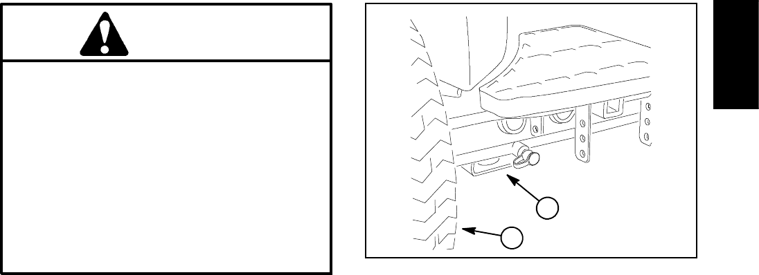
Front End Jacking (Fig. 1)
1. Apply parking brake and chock both rear tires to pre-
vent the machine from moving.
2. Position jack securely below the rectangular pad un-
der the frame axle tube, just to the inside of the front
wheel.
3. Jack front of machine off the ground.
4. Position jack stands under the frame as close to the
raised wheel as possible to support the machine.
Rear End Jacking
1. Apply parking brake and chock both front tires to pre-
vent the machine from moving.
2. Place jack securely at the center of the rear axle un-
der the axle pivot bracket. Jack rear of machine off the
ground.
3. To support the raised machine, position jack stands
under the frame rail next to the axle support bracket.
Figure 1
1. Front wheel 2. Front jacking point
1
2
Safety
Reelmaster 5010- HPage 1 - 6Safety
Safety and Instruction Decals
Numerous safety and instruction decals are affixed to
the traction unit and the cutting units of your Reelmaster.
If any decal becomes illegible or damaged, install a new
decal. Part numbers for decals are listed in your Part
Catalogs. Order replacement decals from your Autho-
rized Toro Distributor.

Reelmaster 5010- H Page 2 - 1 Product Records and Maintenance
Chapter 2
Product Records and Maintenance
Table of Contents
PRODUCT RECORDS 1.........................
MAINTENANCE 1..............................
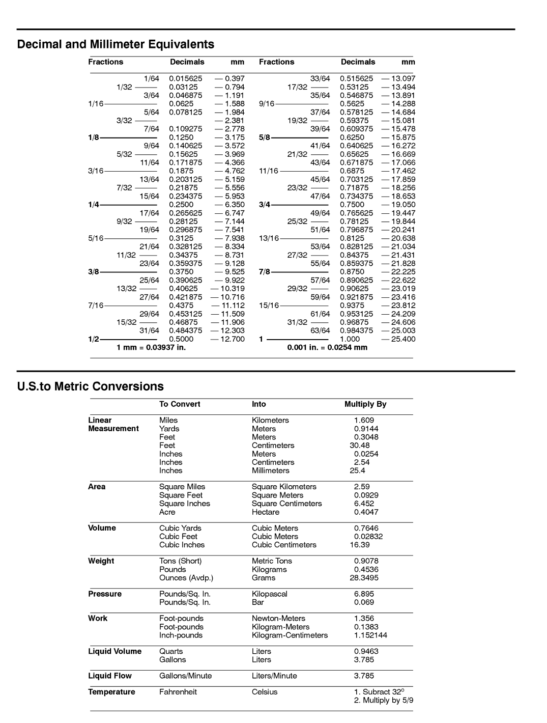
EQUIVALENTS AND CONVERSIONS 2...........
Decimal and Millimeter Equivalents 2............
U.S. to Metric Conversions 2...................
TORQUE SPECIFICATIONS 3...................
Fastener Identification 3.......................
Using a Torque Wrench with an Offset Wrench 3..
Standard Torque for Dry, Zinc Plated and
Steel Fasteners (Inch Series) 4...............
Standard Torque for Dry, Zinc Plated and
Steel Fasteners (Metric Series) 5..............
Other Torque Specifications 6..................
Conversion Factors 6.........................
Product Records
Insert Operator’s Manual and Parts Catalog for your
Reelmaster at the end of this chapter. Refer to Opera-
tor’s Manual for recommended maintenance intervals.
Additionally, insert Installation Instructions, Operator’s
Manuals and Parts Catalogs for any accessories that
have been installed on your Reelmaster at the end of
this section.
Maintenance
Maintenance procedures and recommended service in-
tervals for your Reelmaster are covered in the Opera-
tor’s Manual. Refer to that publication when performing
regular equipment maintenance. Several maintenance
procedures have break- in intervals identified in the Op-
erator’s Manual. Refer to the Engine Operator’s Manual
for additional engine specific maintenance procedures.
Product Records
and Maintenance
0.09375
Reelmaster 5010- HPage 2 - 2Product Records and Maintenance
Equivalents and Conversions
Reelmaster 5010- H Page 2 - 3 Product Records and Maintenance
Torque Specifications
Recommended fastener torque values are listed in the
following tables. For critical applications, as determined
by Toro, either the recommended torque or a torque that
is unique to the application is clearly identified and spe-
cified in this Service Manual.
These Torque Specifications for the installation and
tightening of fasteners shall apply to all fasteners which
do not have a specific requirement identified in this Ser-
vice Manual. The following factors shall be considered
when applying torque: cleanliness of the fastener, use
of a thread sealant (e.g. Loctite), degree of lubrication
on the fastener, presence of a prevailing torque feature
(e.g. Nylock nut), hardness of the surface underneath
the fastener’s head or similar condition which affects the
installation.
As noted in the following tables, torque values should be
reduced by 25% for lubricated fasteners to achieve
the similar stress as a dry fastener. Torque values may
also have to be reduced when the fastener is threaded
into aluminum or brass. The specific torque value
should be determined based on the aluminum or brass
material strength, fastener size, length of thread en-
gagement, etc.
The standard method of verifying torque shall be per-
formed by marking a line on the fastener (head or nut)
and mating part, then back off fastener 1/4 of a turn.
Measure the torque required to tighten the fastener until
the lines match up.
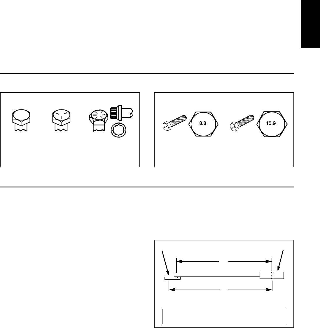
Fastener Identification
Figure 1
Grade 1 Grade 5 Grade 8
Inch Series Bolts and Screws
Figure 2
Class 8.8 Class 10.9
Metric Bolts and Screws
Using a Torque Wrench with an Offset Wrench
Use of an offset wrench (e.g. crowfoot wrench) will affect
torque wrench calibration due to the effective change of
torque wrench length. When using a torque wrench with
an offset wrench, multiply the listed torque recommen-
dation by the calculated torque conversion factor (Fig.
3) to determine proper tightening torque. Tightening
torque when using a torque wrench with an offset
wrench will be lower than the listed torque recommen-
dation.
Example: Themeasuredeffectivelengthofthetorque
wrench (distance from the center of the handle to the
center of the square drive) is 18”.
Themeasuredeffectivelengthofthetorquewrenchwith
the offset wrench installed (distance from the center of
the handle to the center of the offset wrench) is 19”.
Thecalculatedtorqueconversionfactorforthistorque
wrench with this offset wrench would be 18 / 19 = 0.947.
If the listed torque recommendation for a fastener is
from 76 to 94 ft- lb, the proper torque when using this
torque wrench with an offset wrench would be from 72
to 89 ft- lb.
Figure 3
(effective length of
torque wrench)
TORQUE CONVERSION FACTOR = A / B
A
B
(effective length of torque
Torque wrenchOffset wrench
wrench + offset wrench)
Product Records
and Maintenance

Reelmaster 5010- HPage 2 - 4Product Records and Maintenance
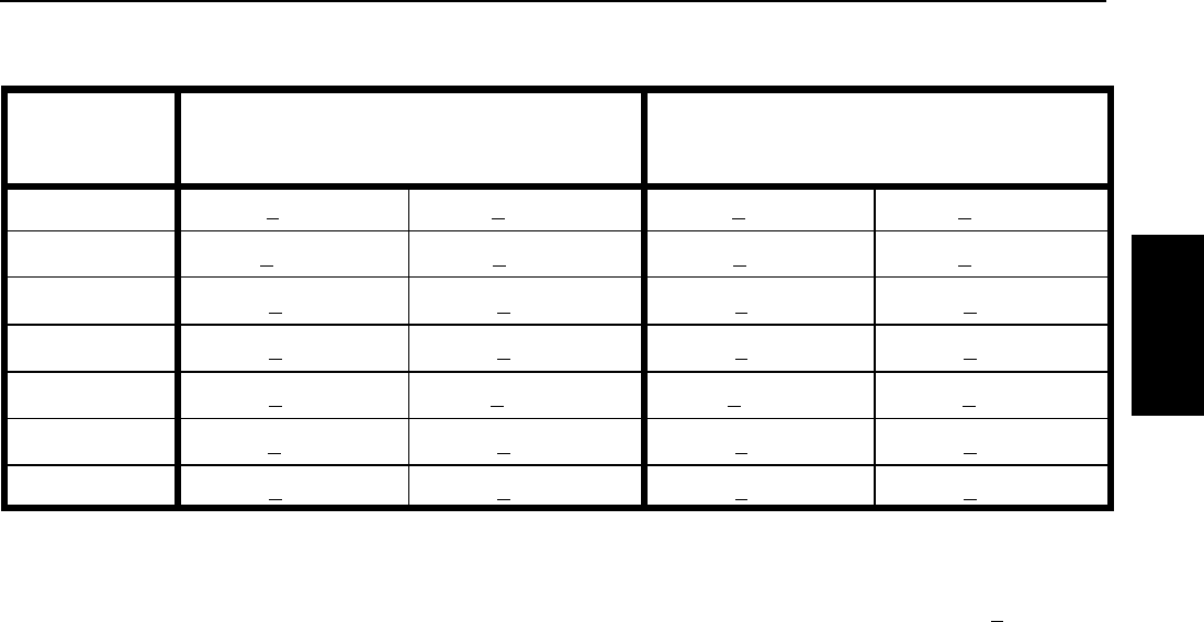
Standard Torque for Dry, Zinc Plated and Steel Fasteners (Inch Series)
Thread Size
Grade 1, 5 &
8withThin
Height Nuts
SAE Grade 1 Bolts, Screws, Studs &
Sems with Regular Height Nuts
(SAE J995 Grade 2 or Stronger Nuts)
SAE Grade 5 Bolts, Screws, Studs &
Sems with Regular Height Nuts
(SAE J995 Grade 2 or Stronger Nuts)
SAE Grade 8 Bolts, Screws, Studs &
Sems with Regular Height Nuts
(SAE J995 Grade 5 or Stronger Nuts)
in- lb in- lb N-cm in- lb N-cm in- lb N-cm
#6- 32UNC
10 + 213 + 2147 + 23
15 + 2169 + 23 23 + 3262 + 34
#6- 40UNF 17 + 2192 + 23 25 + 3282 + 34
#8- 32UNC
13 + 225 + 5282 + 30
29 + 3328 + 34 41 + 5463 + 56
#8- 36UNF 31 + 4350 + 45 43 + 5486 + 56
# 10 - 24 UNC
18 + 230 + 5339 + 56
42 + 5475 + 56 60 + 6678 + 68
#10- 32UNF 48 + 5542 + 56 68 + 7768 + 79
1/4 - 20 UNC 48 + 753 + 7599 + 79 100 + 10 1130 + 113 140 + 15 1582 + 169
1/4 - 28 UNF 53 + 765 + 10 734 + 113 115 + 12 1299 + 136 160 + 17 1808 + 192
5/16 - 18 UNC 115 + 15 105 + 15 1186 + 169 200 + 25 2260 + 282 300 + 30 3390 + 339
5/16 - 24 UNF 138 + 17 128 + 17 1446 + 192 225 + 25 2542 + 282 325 + 33 3672 + 373
ft- lb ft- lb N-m ft- lb N-m ft- lb N-m
3/8 - 16 UNC 16 + 216 + 222 + 330 + 341 + 443 + 558 + 7
3/8 - 24 UNF 17 + 218 + 224 + 335 + 447 + 550 + 668 + 8
7/16 - 14 UNC 27 + 327 + 337 + 450 + 568 + 770 + 795 + 9
7/16 - 20 UNF 29 + 329 + 339 + 455 + 675 + 877 + 8104 + 11
1/2 - 13 UNC 30 + 348 + 765 + 975 + 8102 + 11 105 + 11 142 + 15
1/2 - 20 UNF 32 + 453 + 772 + 985 + 9115 + 12 120 + 12 163 + 16
5/8 - 11 UNC 65 + 10 88 + 12 119 + 16 150 + 15 203 + 20 210 + 21 285 + 28
5/8 - 18 UNF 75 + 10 95 + 15 129 + 20 170 + 18 230 + 24 240 + 24 325 + 33
3/4 - 10 UNC 93 + 12 140 + 20 190 + 27 265 + 27 359 + 37 375 + 38 508 + 52
3/4 - 16 UNF 115 + 15 165 + 25 224 + 34 300 + 30 407 + 41 420 + 43 569 + 58
7/8 - 9 UNC 140 + 20 225 + 25 305 + 34 430 + 45 583 + 61 600 + 60 813 + 81
7/8 - 14 UNF 155 + 25 260 + 30 353 + 41 475 + 48 644 + 65 667 + 66 904 + 89
NOTE: Reduce torque values listed in the table above
by 25% for lubricated fasteners. Lubricated fasteners
are defined as threads coated with a lubricant such as
engine oil or thread sealant such as Loctite.
NOTE: Torque values may have to be reduced when
installing fasteners into threaded aluminum or brass.
The specific torque value should be determined based
on the fastener size, the aluminum or base material
strength, length of thread engagement, etc.
NOTE: The nominal torque values listed above for
Grade 5 and 8 fasteners are based on 75% of the mini-
mum proof load specified in SAE J429. The tolerance is
approximately + 10% of the nominal torque value. Thin
height nuts include jam nuts.
Reelmaster 5010- H Page 2 - 5 Product Records and Maintenance
Standard Torque for Dry, Zinc Plated and Steel Fasteners (Metric Series)
Thread Size
Class 8.8 Bolts, Screws and Studs with
Regular Height Nuts
(Class 8 or Stronger Nuts)
Class 10.9 Bolts, Screws and Studs with
Regular Height Nuts
(Class 10 or Stronger Nuts)
M5 X 0.8 57 + 6in-lb 644 + 68 N- cm 78 + 8in-lb 881 + 90 N- cm
M6 X 1.0 96 + 10 in- lb 1085 + 113 N- cm 133 + 14 in- lb 1503 + 158 N- cm
M8 X 1.25 19 + 2ft-lb 26 + 3N-m 28 + 3ft-lb 38 + 4N-m
M10 X 1.5 38 + 4ft-lb 52 + 5N-m 54 + 6ft-lb 73 + 8N-m
M12 X 1.75 66 + 7ft-lb 90 + 10 N- m 93 + 10 ft- lb 126 + 14 N- m
M16 X 2.0 166 + 17 ft- lb 225 + 23 N- m 229 + 23 ft- lb 310 + 31 N- m
M20 X 2.5 325 + 33 ft- lb 440 + 45 N- m 450 + 46 ft- lb 610 + 62 N- m
NOTE: Reduce torque values listed in the table above
by 25% for lubricated fasteners. Lubricated fasteners
are defined as threads coated with a lubricant such as
engine oil or thread sealant such as Loctite.
NOTE: Torque values may have to be reduced when
installing fasteners into threaded aluminum or brass.
The specific torque value should be determined based
on the fastener size, the aluminum or base material
strength, length of thread engagement, etc.
NOTE: The nominal torque values listed above are
based on 75% of the minimum proof load specified in
SAE J1199. The tolerance is approximately + 10% of the
nominal torque value.
Product Records
and Maintenance
Reelmaster 5010- HPage 2 - 6Product Records and Maintenance
Other Torque Specifications
SAE Grade 8 Steel Set Screws
Thread Size
Recommended Torque
Square Head Hex Socket
1/4 - 20 UNC 140 + 20 in- lb 73 + 12 in- lb
5/16 - 18 UNC 215 + 35 in- lb 145 + 20 in- lb
3/8 - 16 UNC 35 + 10 ft- lb 18 + 3ft-lb
1/2 - 13 UNC 75 + 15 ft- lb 50 + 10 ft- lb
Thread Cutting Screws
(Zinc Plated Steel)
Type 1, Type 23 or Type F
Thread Size Baseline Torque*
No. 6 - 32 UNC 20 + 5in-lb
No. 8 - 32 UNC 30 + 5in-lb
No. 10 - 24 UNC 38 + 7in-lb
1/4 - 20 UNC 85 + 15 in- lb
5/16 - 18 UNC 110 + 20 in- lb
3/8 - 16 UNC 200 + 100 in- lb
Wheel Bolts and Lug Nuts
Thread Size Recommended Torque**
7/16 - 20 UNF
Grade 5
65 + 10 ft- lb 88 + 14 N- m
1/2 - 20 UNF
Grade 5
80 + 10 ft- lb 108 + 14 N- m
M12 X 1.25
Class 8.8
80 + 10 ft- lb 108 + 14 N- m
M12 X 1.5
Class 8.8
80 + 10 ft- lb 108 + 14 N- m
** For steel wheels and non- lubricated fasteners.
Thread Cutting Screws
(Zinc Plated Steel)
Thread
Size
Threads per Inch
Baseline Torque*
Type A Type B
No. 6 18 20 20 + 5in-lb
No. 8 15 18 30 + 5in-lb
No. 10 12 16 38 + 7in-lb
No. 12 11 14 85 + 15 in- lb
* Hole size, material strength, material thickness and fin-
ish must be considered when determining specific
torque values. All torque values are based on non- lubri-
cated fasteners.
Conversion Factors
in-lbX11.2985=N-cm N-cmX0.08851=in-lb
ft- lb X 1.3558 = N- m N- m X 0.7376 = ft- lb

Reelmaster 5010- H Page 3 - 1 Kubota Diesel Engine
Chapter 3
Kubota Diesel Engine
Table of Contents
SPECIFICATIONS 2............................
GENERAL INFORMATION 3.....................
Traction Unit Operator’s Manual 3...............
Kubota Workshop Manual 3....................
48 VDC Battery Disconnect 3...................
SERVICE AND REPAIRS 4......................
Air Cleaner Assembly 4........................
Exhaust System 6............................
Fuel System 8................................
Radiator Assembly 10.........................
Engine 14....................................
Engine Bellhousing Assembly 18................
KUBOTA WORKSHOP MANUAL, DIESEL ENGINE,
05- E4B SERIES
Kubota Diesel
Engine

Reelmaster 5010- HPage 3 - 2Kubota Diesel Engine
Specifications
Item Description
Make / Designation Kubota Model D1105- E4B: 4- Cycle, 3 Cylinder,
Water Cooled, Tier 4 Diesel Engine
Number of Cylinders 3
Bore x Stroke 3.07” x 3.09” (78 mm x 78.4 mm)
Total Displacement 68.5 in3(1123 cc)
Firing Order 1 (fan end) - 2 - 3 (flywheel end)
Direction of Rotation Counterclockwise (viewed from flywheel)
Fuel Diesel or Biodiesel (up to B20) Fuel with
Low or Ultra Low Sulfur Content
Fuel Injection Pump Bosch MD Type Mini Pump
Injection Nozzles Mini Nozzle (DNOPD)
Fuel Tank Capacity 14 U.S. Gallons (53 Liters)
Governor All Speed Mechanical
Low Idle Speed (no load) 1400 RPM
High Idle Speed (no load) 3000 RPM
Engine Oil API CH- 4, CI- 4 or higher
Engine Oil Viscosity See Traction Unit Operator’s Manual
Oil Pump Gear Driven Trochoid Type
Crankcase Oil Capacity 3.5 U.S. Quarts (3.3 Liters) with Filter
Cooling System Capacity (including reserve tank) 5.5 U.S. Quarts (5.2 Liters)
Starter 12 VDC 1.4 KW
Alternator/Regulator 12 VDC 40 Amp
Dry Weight (approximate) 205 lb. (93 kg)
NOTE: The Kubota engine used in your Reelmaster is
equipped with a mechanical governor as listed above.
During normal machine operation however, engine
speed control is electronically managed by the machine
TEC controller, the 48 VDC motor/generator controller
and the engine mounted fuel actuator. These three (3)
machine components determine engine/generator
speed during use and modify fuel settings at the fuel ac-
tuator as necessary to maintain appropriate engine
speed based on load.
Reelmaster 5010- H Page 3 - 3 Kubota Diesel Engine
General Information
This Chapter gives information about specifications,
troubleshooting, testing and repair of the Kubota diesel
engine used in Reelmaster 5010- H machines.
Most repairs and adjustments require tools which are
commonly available in many service shops. The use of
some specialized test equipment is explained in the en-
gine Kubota Workshop Manual included at the end of
this chapter. However, the cost of the test equipment
and the specialized nature of some repairs may dictate
that the work be done at an engine repair facility.
Service and repair parts for Kubota diesel engines are
supplied through your local Toro Distributor. If an engine
parts list is not available, be sure to provide your distrib-
utor with the Toro model and serial number.
Traction Unit Operator’s Manual
The Traction Unit Operator’s Manual provides informa-
tion regarding the operation, general maintenance and
maintenance intervals for the Kubota diesel engine that
powers your Reelmaster machine. The Kubota Operat-
or’s Manual includes information specific to the engine
used in your Reelmaster. Refer to these publications for
additional information when servicing the machine.
Kubota Workshop Manual
The engine that powers your Reelmaster machine is a
Kubota model D1105- E4B (Tier 4 compliant). The Kub-
ota Workshop Manual, Diesel Engine, 05- E4B Series is
available for this engine. Make sure that the correct en-
gine manual is used when servicing the engine on your
Reelmaster.
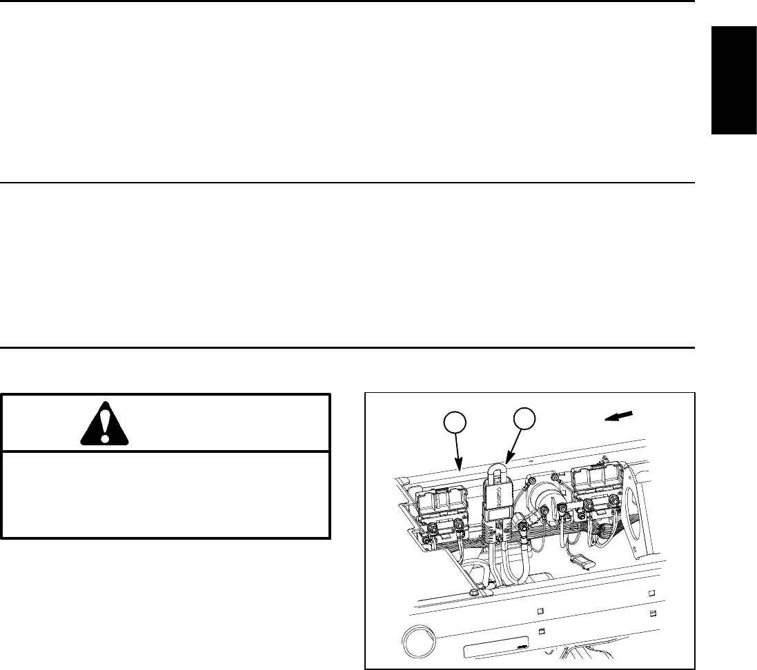
48 VDC Battery Disconnect
CAUTION
Before installing, removing or servicing compo-
nents in the 48 VDC system (e.g. cutting unit mo-
tors, motor/generator), separate the 48 VDC bat-
tery disconnect. This will prevent unexpected
operation of 48 VDC system components.
The 48 VDC battery disconnect is attached to the right
frame rail under the operator seat (Fig. 1). Unplug the
disconnect to make sure that 48 VDC components do
not operate unexpectedly. Apply dielectric grease to the
contact surfaces of the battery disconnect and plug the
battery disconnect back in after service to the 48 VDC
system is completed.
1. RH frame rail 2. 48V battery disconnect
Figure 1
2
1FRONT
Kubota Diesel
Engine
Reelmaster 5010- HPage 3 - 4Kubota Diesel Engine
Service and Repairs
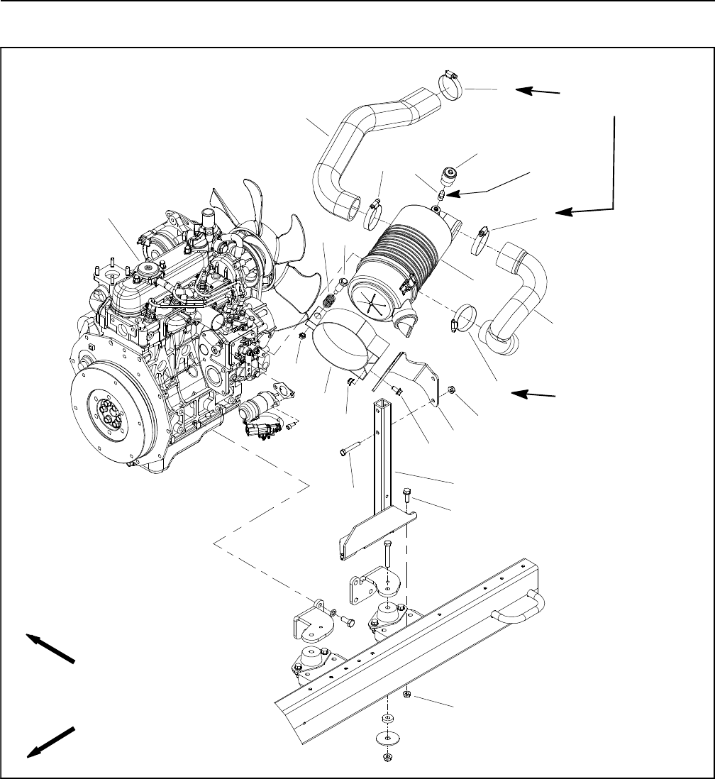
Air Cleaner Assembly
Figure 2
1. Diesel engine
2. Air cleaner assembly
3. Hose clamp (4 used)
4. Air intake hose
5. Air intake hose
6. Service indicator
7. Indicator adapter
8. Shoulder bolt
9. Nut
10. Compression spring
11. Air cleaner mounting band
12. Flange nut (6 used)
13. Flange head screw (2 used)
14. Cap screw (2 used)
15. Flange head screw (2 used)
16. Air cleaner bracket
17. Air cleaner stand
FRONT
RIGHT
Thread
Sealant
30 to 40 in- lb
(3.4 to 4.5 N- m)
2
3
6
8
9
10
11
13
1
5
7
12
14
15
16
17
4
3
3
3
12
12
30 to 40 in- lb
(3.4 to 4.5 N- m)
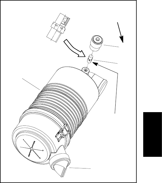
Reelmaster 5010- H Page 3 - 5 Kubota Diesel Engine
Removal (Fig. 2)
1. Park machine on a level surface, lower cutting units,
stop engine, engage parking brake and remove key
from the ignition switch. Raise and support hood.
2. Remove air cleaner components as needed using
Figure 2 as a guide.
3. See Traction Unit Operator’s Manual for air cleaner
service and maintenance procedures.
Installation (Fig. 2)
IMPORTANT: Any leaks in the air filter system will
allow dirt into engine and will cause serious engine
damage. Make sure that all air cleaner components
are in good condition and are properly secured dur-
ing assembly.
1. Assemble air cleaner system using Figure 2 as a
guide.
A. If service indicator (item 6 in Fig. 2) and adapter
(item 7 in Fig. 2) were removed from air cleaner
housing, apply thread sealant to adapter threads be-
fore installing adapter and indicator to housing.
Install adapter so that grooves in adapter hex and
adapter filter element are installed toward service in-
dicator (shown in Fig. 3). Torque indicator from 12 to
15 in- lb (1.4 to 1.6 N- m).
B. Make sure that evacuator valve on air cleaner as-
sembly is pointed down after assembly.
C. Torque hose clamps from 30 to 40 in- lb (3.4 to
4.5 N- m).
2. After air cleaner has been properly installed, lower
and secure hood.
Figure 3
1. Air cleaner assembly
2. Service indicator
3. Indicator adapter
4. Evacuator valve
12 to 15 in- lb
(1.4 to 1.6 N- m)
3
1
2
4
Thread
Sealant
Kubota Diesel
Engine
Reelmaster 5010- HPage 3 - 6Kubota Diesel Engine
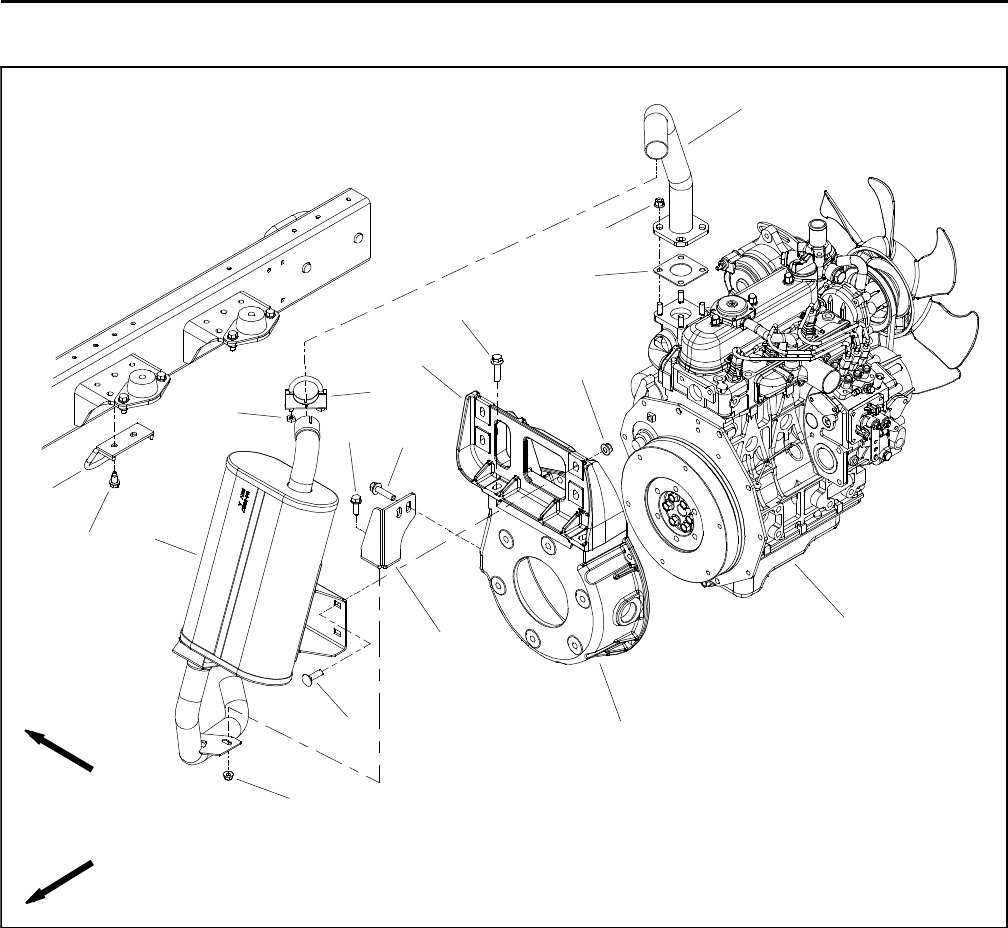
Exhaust System
Figure 4
1. Diesel engine
2. Exhaust muffler
3. Clamp
4. Hex nut (2 used)
5. Flange nut (4 used)
6. Carriage bolt (4 used)
7. Bellhousing
8. Tailpipe bracket
9. Flange head screw
10. Flange nut
11. Exhaust header
12. Flange nut (4 used)
13. Exhaust gasket
14. Flange head screw (6 used)
15. Muffler guard
16. Washer head screw (2 used)
17. Muffler bracket
2
3
6
8
9
10
11
13
1
5
7
12
14
15
16
4
14
17
FRONT
RIGHT
Reelmaster 5010- H Page 3 - 7 Kubota Diesel Engine
Removal (Fig. 4)
CAUTION
The muffler and exhaust pipe may be hot. To
avoid possible burns, allow the engine and ex-
haust system to cool before working on the ex-
haust system.
1. Raise and support hood to gain access to exhaust
system. Allow engine and exhaust system to cool before
doing any disassembly of exhaust system components.
2. Remove exhaust system components from the en-
gine as necessary using Figure 4 as a guide. Discard ex-
haust gasket (item 13) if exhaust header (item 11) was
removed.
Installation (Fig. 4)
IMPORTANT: If exhaust studs were removed from
engine cylinder head, thoroughly clean threads in
head and apply Loctite #277 (or equivalent) to stud
threads before installing studs into head.
NOTE: Make sure that all exhaust system flanges and
sealing surfaces are free of debris or damage that may
prevent a tight seal.
1. Install new exhaust gasket (item 13) if gasket was
removed. Do not use any type of gasket sealant on gas-
ket or flange surfaces.
2. Install all removed exhaust system components us-
ing Figure 4 as a guide. Hand tighten exhaust system
fasteners and after all exhaust system components
have been installed, fully tighten the fasteners as shown
in Figure 5:
A. Tighten flange head screws that secure muffler
bracket to engine bellhousing.
B. Tighten carriage screws and flange nuts that se-
cure exhaust muffler to muffler bracket.
C. Tighten flange nuts that secure exhaust header
to engine exhaust manifold.
D. Tighten clamp that secures exhaust muffler to ex-
haust header.
E. Tighten flange head screw and flange nut that se-
cures exhaust muffler to tailpipe bracket.
F. Tighten flange head screws that secure tailpipe
bracket to engine bellhousing.
3. Adjust muffler guard (item 15) on frame so there is
⅜” (9.5 mm) clearance between exhaust tailpipe and
guard in all directions.
4. After all exhaust components have been installed,
lower and secure hood.
Figure 5
B
A
C
D
E
F
Kubota Diesel
Engine
Reelmaster 5010- HPage 3 - 8Kubota Diesel Engine
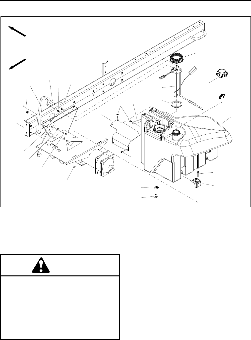
Fuel System
Figure 6
1. Fuel tank
2. Fuel tank cap
3. Screw (7 used)
4. Strap
5. Sender cover
6. Hose clamp
7. Fuel supply hose
8. Hose clamp
9. Fuel return hose
10. Clamp (2 used)
11. Flange head screw (2 used)
12. Flange nut (3 used)
13. Draincock
14. Hose clamp
15. Cap screw
16. Flat washer
17. Bumper
18. Fuel sender cap
19. Fuel sender
20. Gasket
FRONT
RIGHT
3
6
8
9
10
11
13
5
7
16
18
20
12
2
1
4
3
12
14
15
17
19
DANGER
Because diesel fuel is flammable, use caution
when storing or handling it. Do not smoke while
filling the fuel tank. Do not fill fuel tank while en-
gine is running, when engine is hot or when ma-
chine is in an enclosed area. Always fill fuel tank
outside and wipe up any spilled diesel fuel be-
fore starting the engine. Store fuel in a clean,
safety- approved container and keep container
cap in place. Use diesel fuel for the engine only;
not for any other purpose.
Check Fuel Lines and Connections
Check fuel lines and connections periodically as recom-
mended in the Traction Unit Operator’s Manual. Check
lines for deterioration, damage, leakage or loose con-
nections. Replace fuel hoses, clamps and connections
as necessary.
Drain and Clean Fuel Tank
Drain and clean the fuel tank periodically as recom-
mended in the Traction Unit Operator’s Manual. Also,
drain and clean the fuel tank if the fuel system becomes
contaminated or if the machine is to be stored for an ex-
tended period.
Reelmaster 5010- H Page 3 - 9 Kubota Diesel Engine
IMPORTANT: Follow all local codes and regula-
tions when recycling or disposing waste fuel.
To clean fuel tank, flush tank out with clean diesel fuel.
Make sure tank is free of all contaminates and debris.
Priming the Fuel System
The fuel system needs to be primed before starting the
engine for the first time, after running out of fuel or after
fuel system maintenance (e.g. draining the filter/water
separator, replacing a fuel hose). To prime the fuel sys-
tem, make sure that the fuel tank has fuel in it. Then, turn
the ignition key to the RUN position for ten (10) to fifteen
(15) seconds which allows the fuel pump to prime the
fuel system. DO NOT use the engine starter motor to
crank the engine in order to prime the fuel system.
Fuel Tank Removal (Fig. 6)
1. Park machine on a level surface, lower cutting units,
stop engine, engage parking brake and remove key
from the ignition switch.
2. Place drain pan under fuel tank. Make sure that drain
pan is large enough to hold fuel tank contents (see
Specifications in this chapter).
3. Open draincock on bottom of fuel tank and allow tank
to fully drain. Close draincock.
4. Disconnect wire harness connection from the fuel
sender (item 19).
NOTE: Before removing fuel hoses from tank fittings,
label hoses for assembly purposes.
IMPORTANT: To prevent damage to fuel hoses, nu-
merous cable ties are used to secure hoses to ma-
chine components. Take note of all cable ties that
are removed from machine during fuel tank removal
so they can be properly replaced during tank in-
stallation.
5. Loosen hose clamps and carefully disconnect sup-
ply (item 7) and return (item 9) fuel hoses from fittings
on the top of the fuel sender.
6. Remove fuel tank using Figure 6 as a guide.
IMPORTANT: If fuel sender is removed from fuel
tank, note orientation of fittings for assembly pur-
poses (Fig. 7).
Fuel Tank Installation (Fig. 6)
1. Install fuel tank to frame using Figure 6 as a guide.
Secure fuel hoses with cable ties as noted during fuel
tank removal.
A. If fuel sender was removed from fuel tank, make
sure that fuel fittings on sender are orientated at 90o
from right side of tank as shown in Figure 7. Also, to
prevent damage to fuel sender during assembly,
make sure that fuel sender does not turn as sender
cap is tightened.
2. Correctly connect supply (item 7) and return (item 9)
fuel hoses to fittings on the top of the fuel sender. Secure
fuel hoses with hose clamps.
3. Secure wire harness connector to fuel sender.
4. Make sure that fuel tank draincock is closed. Fill fuel
tank with clean fuel.
5. Prime the fuel system (see above).
6. Before returning machine to operation, make sure
that no fuel leaks exist.
Figure 7
1. Fuel sender
2. Fuel supply fitting
3. Fuel return fitting
3
12
90o
FRONT
Kubota Diesel
Engine
Reelmaster 5010- HPage 3 - 10Kubota Diesel Engine
Radiator Assembly
Figure 8
1. Coolant reservoir
2. Hose clamp (3 used)
3. Hose
4. Foam seal (2 used)
5. Oil cooler
6. Hose
7. Hose clamp (4 used)
8. Foam seal (2 used)
9. Radiator cap
10. Flange nut (14 used)
11. Rear screen
12. Foam seal
13. Spacer (5 used)
14. Flange head screw (5 used)
15. Air intake screen
16. Draincock
17. Foam seal (2 used)
18. Radiator
19. Radiator frame
20. Reservoir bracket
21. Reservoir bracket
22. Upper radiator hose
23. Lower radiator hose
24. Fan shroud
25. Flange head screw
26. Lock nut
27. Flange head screw (9 used)
28. Foam seal (2 used)
29. Foam seal (2 used)
30. Mount plate (2 used)
31. Washer head screw (6 used)
FRONT
RIGHT
30 to 40 in- lb
(3.4 to 4.5 N- m)
2
3
8
9
10
1
5
16
17
18
19
20
4
21
23
24
25
26
27
11
15
6
12
13 14
28
29
2
10
2
10
7
722
30
31
Reelmaster 5010- H Page 3 - 11 Kubota Diesel Engine
Removal (Fig. 8)
1. Park machine on a level surface, lower cutting
decks, stop engine, apply parking brake and remove
key from the ignition switch.
2. Unlatch rear screen, lift screen from hinges and re-
move screen from machine.
3. Remove 12 volt battery from rear of machine to ease
oil cooler removal (see 12 VDC Battery Service in the
Service and Repairs section of Chapter 5 - Electrical
System).
4. Rotate clamps that secure oil cooler to radiator
frame. Carefully lift and remove oil cooler from radiator
frame. Position and support oil cooler away from the ra-
diator.
5. Raise and support the hood.
CAUTION
Do not open radiator cap or drain coolant if the
radiator or engine is hot. Pressurized, hot cool-
ant can escape and cause burns.
Ethylene- glycol antifreeze is poisonous. Dis-
pose of coolant properly, or store it in a properly
labeled container away from children and pets.
6. Drain radiator into a suitable container either by us-
ing the draincock (item 16) on the left side of the radiator
or by disconnecting the lower radiator hose from the ra-
diator. Make sure that drain container is large enough to
hold cooling system contents (see Specifications in this
Chapter).
IMPORTANT: Follow all local codes and regula-
tions when recycling or disposing engine coolant.
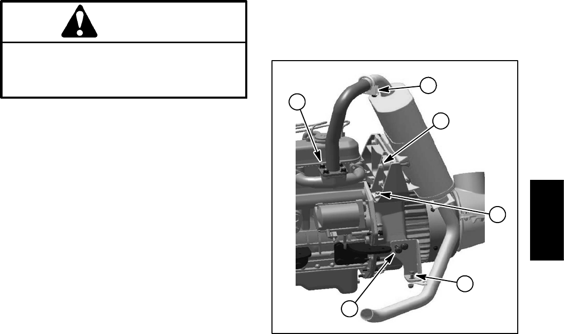
7. Disconnect air cleaner and motor/generator intake
hoses from fan shroud (Fig. 9).
8. Disconnect radiator hoses (upper and lower) from
the radiator.
9. At rear of radiator frame, carefully cut the upright
foam seals (item 4) at the junction of the radiator frame
and the machine frame. This will allow the radiator frame
to be removed from the machine without removing the
foam seal from the radiator and machine frames.
10.Remove six (6) washer head screws (item 31) that
secure the radiator frame (item 19) to the frame.
11. Carefully raise radiator assembly (radiator, fan
shroud, coolant reservoir and radiator frame) from the
machine.
Figure 9
1. Fan shroud
2. Air cleaner intake hose
3. Hose clamp
4. Generator intake hose
5. Hose clamp
2
3
1
4
5
FRONT
RIGHT
30 to 40 in- lb
(3.4 to 4.5 N- m)
30 to 40 in- lb
(3.4 to 4.5 N- m)
12.Plug radiator and hose openings to prevent contami-
nation.
13.Disassemble radiator assembly as needed using
Figure 8 as a guide.
Installation (Fig. 8)
1. Inspect all foam seals placed between radiator, fan
shroud and radiator frame. Replace damaged foam
seals.
2. Remove plugs placed in radiator and hose openings
during the removal procedure.
3. Install all removed components to radiator frame us-
ing Figure 8 as a guide.
4. Carefully lower radiator assembly with radiator, fan
shroud, coolant reservoir and radiator frame to the ma-
chine frame.
5. Secure the radiator frame (item 19) to the frame with
six (6) washer head screws (item 31).
6. Make sure that at least 0.250” (6.4 mm) clearance
exists at all points between fan shroud opening and fan.
7. Connect upper and lower radiator hoses to radiator
and secure with hose clamps. Torque hose clamps from
30 to 40 in- lb (3.4 to 4.5 N- m).
Kubota Diesel
Engine
Reelmaster 5010- HPage 3 - 12Kubota Diesel Engine
8. Connect air cleaner and motor/generator intake
hoses to fan shroud and secure with hose clamps (Fig.
9). Torque hose clamps from 30 to 40 in- lb (3.4 to 4.5
N- m).
9. Make sure radiator draincock is closed (threaded out
fully).
10.Fill radiator and coolant reservoir with coolant.
11. Lower and secure hood.
12.Carefully position and install oil cooler to radiator
frame. Rotate clamps to secure oil cooler to radiator
frame.
13.Install 12 volt battery (see 12 VDC Battery Service
in the Service and Repairs section of Chapter 5 - Electri-
cal System).
14.Install and latch rear screen.

Reelmaster 5010- H Page 3 - 13 Kubota Diesel Engine
This page is intentionally blank.
Kubota Diesel
Engine
Reelmaster 5010- HPage 3 - 14Kubota Diesel Engine
Engine
Figure 10
FRONT
RIGHT
1. Diesel engine
2. Cap screw (12 used)
3. Flange head screw (4 used)
4. Snubbing washer (4 used)
5. Cap screw (4 used)
6. Flange nut (8 used)
7. Flange nut (8 used)
8. Spacer (4 used)
9. Lock washer (12 used)
10. Engine mount (2 used)
11. RH engine mount
12. Exhaust gasket
13. Bellhousing
14. Flange nut (4 used)
15. Tailpipe bracket
16. Service indicator
17. Air cleaner assembly
18. Air intake hose
19. Air intake hose
20. Air cleaner bracket
21. Air cleaner stand
22. Hose clamp (4 used)
23. Indicator adapter
24. Muffler bracket
25. Exhaust header
26. Exhaust muffler
27. Clamp
28. Flange head screw (2 used)
29. Nut
30. Air cleaner mounting band
31. Cap screw (2 used)
32. Compression spring
33. Muffler guard
34. Washer head screw (2 used)
35. Temperature sender
36. Socket head screw (2 used)
37. Fuel actuator
38. LH engine mount
39. Extension spring
40. Throttle spring bracket
41. Cap screw
42. Cap screw
43. Fuel actuator gasket
44. Flange head screw (6 used)
45. Carriage bolt (4 used)
46. Shoulder bolt
Thread
Sealant
2
36
8
9
10
11
13
1
5
7
12
14
15
16
17
18
19
20
4
21
22
23
24
25
26
27
28
29
30
31
32
33
34
35
36
37
38
39
40
44
44
45
22
22
22
7
6
3
7
41
42
43 7
46
34 to 42 ft- lb
(47to56N-m)
30 to 40 in- lb
(3.4 to 4.5 N- m)
Reelmaster 5010- H Page 3 - 15 Kubota Diesel Engine
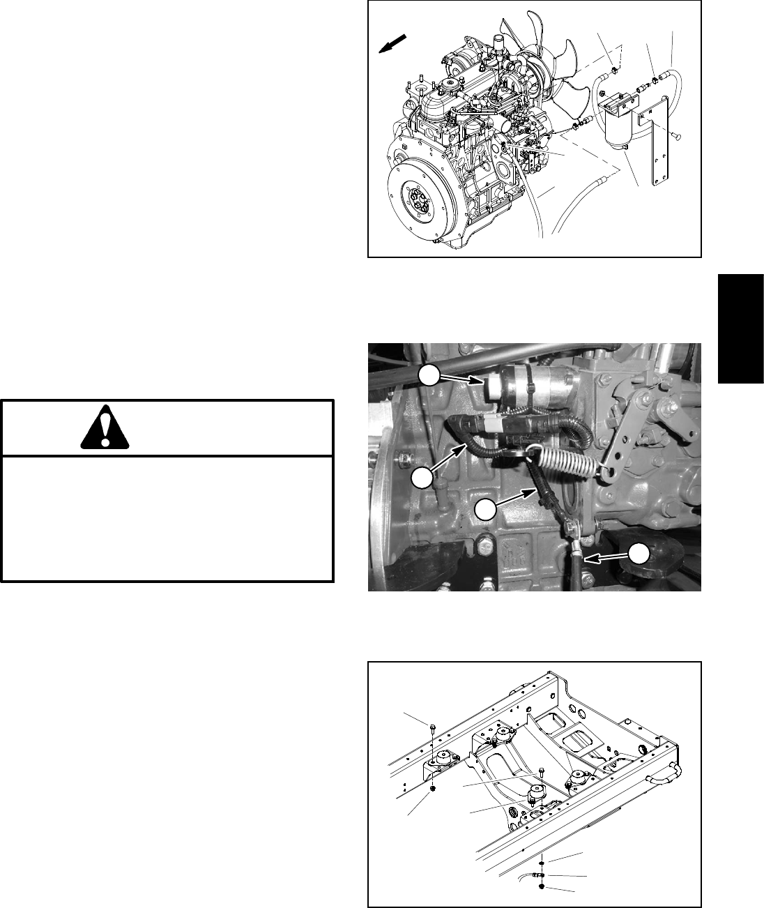
Engine Removal (Fig. 10)
1. Park machine on a level surface, lower cutting units,
stop engine and remove key from the ignition switch.
Chock wheels to keep the machine from moving.
2. Disconnect negative (- ) and then positive (+) battery
cables from the 12 volt battery at the rear of the machine
(see 12 VDC Battery Service in the Service and Repairs
section of Chapter 5 - Electrical System).
3. Open and support hood.
4. Separate system components from the 48 VDC bat-
tery pack by unplugging the 48 VDC battery disconnect.
(see 48 VDC Battery Disconnect in the General Infor-
mation section of this chapter). This will prevent unex-
pected 48 VDC system component operation.
5. Remove air cleaner from machine (see Air Cleaner
Assembly in this section).
6. Remove exhaust muffler from machine (see Ex-
haust System in this section).
CAUTION
Do not open radiator cap or drain coolant if the
radiator or engine is hot. Pressurized, hot cool-
ant can escape and cause burns.
Ethylene- glycol antifreeze is poisonous. Dis-
pose of coolant properly, or store it in a properly
labeled container away from children and pets.
7. Drain radiator into a suitable container either by us-
ing the draincock on the left side of the radiator or by dis-
connecting the lower radiator hose from the radiator.
Make sure that drain container is large enough to hold
cooling system contents (see Specifications in this
Chapter).
IMPORTANT: Follow all local codes and regula-
tions when recycling or disposing engine coolant.
8. Disconnect hoses from engine:
A. Loosen clamps and remove upper and lower ra-
diator hoses from the engine.
B. Disconnect fuel supply and return hoses from en-
gine (Fig. 11).
C. Plug disconnected hoses and engine openings to
prevent leakage and contamination. Position discon-
nected hoses away from engine.
Figure 11
1. Fuel supply hose
2. Hose clamp
3. Fuel return hose
4. Hose clamp
5. Separator
FRONT 2
3
1
5
4
2
Figure 12
1. Fuel actuator
2. Fuel actuator connector
3. Wire harness ground
4. Negative battery cable
1
4
3
2
Figure 13
1. Engine mount (4 used)
2. Screw (2 per mount)
3. Nut (2 per mount)
4. Lock washer
5. Ground cable
1
2
4
5
3
2
3
Kubota Diesel
Engine
Reelmaster 5010- HPage 3 - 16Kubota Diesel Engine
9. Disconnect hydraulic pump drive shaft from 48 VDC
motor/generator (see Hydraulic Pump Drive Shaft in the
Service and Repairs section of Chapter 4 - Hydraulic
System). Position and support drive shaft away from
motor/generator and engine.
IMPORTANT: To prevent damage to electrical wire
harness, numerous cable ties are used to secure
harness to machine components. Take note of all
cable ties that are removed from machine during
engine removal so they can be properly replaced
during engine installation.
10.Note location of cable ties used to secure wire har-
ness to the machine for assembly purposes. Disconnect
wires and/or electrical connections from the following
engine electrical components:
A. The wire harness connectors from the alternator,
temperature sender, oil pressure switch, starter mo-
tor solenoid and fuel actuator.
B. The wire harness ring terminals from the alterna-
tor and glow plug bus.
C. The positive battery cable and fusible link har-
ness from the engine starter motor.
D. The negative battery cable and wire harness
ground at the engine block under the fuel actuator
(Fig. 12).
E. The wire harness connector from the 48 VDC
motor/generator assembly.
CAUTION
Make sure that hoist or lift used to remove en-
gine assembly can properly support engine and
attached components. Engine assembly weighs
approximately 280 pounds (127 kg).
11. Connect suitable lift or hoist to the lift brackets on
each end of the engine cylinder head.
12.Remove flange nuts, rebound washers, spacers and
cap screws that secure the engine mount brackets to
the engine mounts.
CAUTION
One person should operate hoist or lift while a
second person guides the engine out of the ma-
chine.
IMPORTANT: Make sure to not damage the engine,
fuel hoses, hydraulic lines, electrical harness, ra-
diator or other parts while removing the engine.
13.Carefully raise engine from machine moving it to-
ward the front of the machine and away from radiator as-
sembly.
14.If necessary, remove engine mount brackets from
engine.
15.If necessary, remove engine mounts from machine
frame (Fig. 13). Note that front engine mount on left side
of machine has the negative battery cable ground con-
nection secured with one of the mount bolts. If removed,
make sure to locate lock washer that should be installed
between the cable connection and the frame.
16.If necessary, remove 48 VDC motor/generator from
engine (see 48 VDC Motor/Generator Assembly in the
Service and Repairs section of Chapter 5 - Electrical
System).
Engine Installation (Fig. 10)
1. Locate machine on a level surface with cutting units
lowered and key removed from the ignition switch.
Chock wheels to keep the machine from moving.
2. Make sure that all parts removed from the engine
during maintenance or rebuilding are installed to the en-
gine.
3. If engine mount brackets were removed from the en-
gine, secure brackets to engine with lock washers and
cap screws. Torque cap screws from 34 to 42 ft- lb (47
to 56 N- m).
4. If removed, install 48 VDC motor/generator and bell-
housing assembly to engine (see 48 VDC Motor/Gener-
ator Assembly in the Service and Repairs section of
Chapter 5 - Electrical System).
5. If removed, secure engine mounts to frame machine
frame (Fig. 13). Make sure that negative battery cable
ground connection is secured with lock washer between
the cable connection and the frame if front engine mount
on left side of machine was removed.
6. Connect suitable lift or hoist to the engine lift brack-
ets.

Reelmaster 5010- H Page 3 - 17 Kubota Diesel Engine
CAUTION
One person should operate lift or hoist while a
second person guides the engine into the ma-
chine.
IMPORTANT: Make sure to not damage the engine,
fuel hoses, hydraulic lines, electrical harness, ra-
diator or other parts while installing the engine.
7. Carefully lower engine to the mounts secured to the
machine frame. Make sure fastener holes of the engine
mount brackets are aligned with the holes in the engine
mounts.
8. Insert cap screw down through each engine mount
bracket and mount. Place spacer, snubbing washer and
then flange nut on four (4) cap screws. Tighten fasteners
to secure engine to engine mounts.
9. Connect hydraulic pump drive shaft to motor/gener-
ator output shaft (see Hydraulic Pump Drive Shaft in the
Service and Repairs section of Chapter 4 - Hydraulic
System).
10.Connect all wire harness connectors to correct en-
gine components. Secure wire harness to the machine
with cable ties in locations noted during engine removal.
11. Remove plugs installed in fuel and coolant hoses
and engine openings during disassembly. Connect
hoses to the engine:
A. Connect fuel supply and fuel return hoses to en-
gine fittings (Fig. 11). Secure fuel hoses with hose
clamps.
B. Connect upper and lower radiator hoses to the
engine. Secure hoses with hose clamps. Torque
hose clamps from 30 to 40 in- lb (3.4 to 4.5 N- m).
12.Install air cleaner (see Air Cleaner Assembly in this
section).
13.Install exhaust muffler to machine (see Exhaust Sys-
tem in this section). Make sure that exhaust tube has ⅜”
(9.5 mm) clearance with guard in all directions after as-
sembly.
14.Make sure radiator draincock is closed (threaded out
fully). Fill radiator and coolant reservoir with coolant.
15.Check engine oil level and adjust if needed.
16.Check and adjust oil level in hydraulic reservoir as
needed.
17.Plug the 48 VDC battery disconnect back in.
18.Close and secure hood.
19.Connect positive (+) and then negative (- ) battery
cables to the 12 volt battery (see 12 VDC Battery Ser-
vice in the Service and Repairs section of Chapter 5 -
Electrical System).
20.Prime the fuel system (see Fuel System in this sec-
tion).
21.Start engine and operate hydraulic controls to prop-
erly fill hydraulic system (see Charge Hydraulic System
in the Service and Repairs section of Chapter 4 - Hy-
draulic System).
Kubota Diesel
Engine
Reelmaster 5010- HPage 3 - 18Kubota Diesel Engine
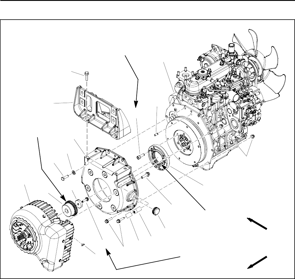
Engine Bellhousing Assembly
Figure 14
1. Diesel engine
2. Motor/generator assembly
3. Flange head screw
4. Collar
5. Coupler hub
6. Woodruff key
7. Bellhousing
8. Cap screw (2 used)
9. Flat washer (2 used)
10. Flange head screw (7 used)
11. Flange nut (2 used)
12. R- clamp (for generator wire harness)
13. Clamp (for fuel return hose)
14. Caplug
15. Flange head screw (6 used)
16. Dowel pin (2 used)
17. Coupler flange
18. Socket head screw (3 used)
19. Muffler bracket
20. Flange head screw (4 used)
3
9
10
11
54
13
2
6
8
1
7
12
14
15
16
17
18
19
20
FRONT
RIGHT
50 to 60 ft- lb
(68to81N-m)
25 to 31 ft- lb
(34to42N-m)
Antiseize
Lubricant
Antiseize
Lubricant
The 48 VDC motor/generator is attached to the engine
bellhousing with six (6) flange head screws. Access to
these screws requires the bellhousing and motor/gener-
ator to be removed from the engine as an assembly. For
recommended procedures to remove the bellhousing
and motor/generator assembly from the engine, see 48
VDC Motor/Generator Assembly in the Service and Re-
pairs section of Chapter 5 - Electrical System.

Reelmaster 5010- H Hydraulic SystemPage 4 - 1
Chapter 4
Hydraulic System
Table of Contents
SPECIFICATIONS 2............................
GENERAL INFORMATION 3.....................
Traction Unit Operator’s Manual 3..............
48 VDC Battery Disconnect 3..................
Check Hydraulic Fluid 3.......................
Towing Traction Unit 4.........................
Hydraulic Hoses 4............................
Hydraulic Hose and Tube Installation 5..........
Hydraulic Fitting Installation 6..................
Relieving Hydraulic System Pressure 8..........
Traction Circuit Component Failure 8............
HYDRAULIC SCHEMATIC 10....................
HYDRAULIC FLOW DIAGRAMS 12...............
Traction Circuit 12............................
Lift Circuit: Raise Cutting Units 14...............
Lift Circuit: Lower Cutting Units 16..............
Steering Circuit 18............................
SPECIAL TOOLS 20............................
TROUBLESHOOTING 25........................
General Hydraulic System Problems 25..........
Traction Circuit Problems 26...................
Lift Circuit Problems 27........................
Steering Circuit Problems 28...................
TESTING 30...................................
Traction Circuit Relief Valve (R3) and (R4)
Pressure Test 32............................
Traction Circuit Charge Pressure Test 34.........
Gear Pump (P2) Flow Test 36..................
Front Wheel Motor Efficiency Test 38............
Piston (Traction) Pump Flow Test 40............
Lift Relief Valve (SVRV) Pressure Test 42........
Gear Pump (P1) Flow Test 44..................
Lift Cylinder Internal Leakage Test 46............
Steering Relief Valve (R10) Pressure Test 48.....
Steering Cylinder Internal Leakage Test 50.......
SERVICE AND REPAIRS 52.....................
General Precautions for Removing and Installing
Hydraulic System Components 52.............
Check Hydraulic Lines and Hoses 53............
Flush Hydraulic System 54.....................
Filtering Closed- Loop Traction Circuit 55........
Hydraulic System Start- up 56..................
Hydraulic Reservoir 58........................
Piston (Traction) Pump Control Assembly 60.....
Hydraulic Pump Assembly 62..................
Piston (Traction) Pump Service 66..............
Gear Pump Service 68........................
Hydraulic Pump Drive Shaft 70.................
Hydraulic Pump Drive Shaft Cross and
Bearing Service 72..........................
Front Wheel Motors 74........................
Front Wheel Motor Service 76
..................
Rear Wheel Motors (Machines with Optional
CrossTraxTM Kit) 78.........................
Rear Wheel Motor Service (Machines with Optional
CrossTraxTM Kit) 80.........................
Control Manifold Cartridge Valve Service 81......
Lift Control Manifold 82........................
Lift Control Manifold Service 84.................
CrossTraxTM AWD Manifold (Machines with
Optional CrossTraxTM Kit) 86.................
CrossTraxTM AWD Manifold Service (Machines
with Optional CrossTraxTM Kit) 88.............
Lift Cylinders 90..............................
Lift Cylinder Service 92........................
Steering Control Valve 94......................
Steering Control Valve Service 96...............
Steering Cylinder 98..........................
Steering Cylinder Service 100..................
Hydraulic Oil Cooler 102.......................
SAUER- DANFOSS LPV CLOSED CIRCUIT AXIAL
PISTON PUMPS REPAIR MANUAL
SAUER- DANFOSS LPV CLOSED CIRCUIT AXIAL
PISTON PUMPS SERVICE INSTRUCTIONS
EATON DELTA MOTORS PARTS AND REPAIR
MANUAL
PARKER TORQMOTORTM SERVICE PROCEDURE
(TC, TB, TE, TJ, TF, TG, TH AND TL SERIES)
SAUER- DANFOSS STEERING UNIT TYPE OSPM
SERVICE MANUAL
Hydraulic
System

Reelmaster 5010- HHydraulic System Page 4 - 2
Specifications
Item Description
Piston (Traction) Pump Closed Circuit Axial Piston Design
Maximum Pump Displacement (per revolution) 2.14 Cubic Inches (35 cc)
Gear Pump 2 Section, Positive Displacement Gear Type Pump
Section P1 Displacement (per revolution) (all models) 0.24 Cubic Inches (3.96 cc)
Section P2 Displacement (per revolution) (all models) 0.40 Cubic Inches (6.61 cc)
Charge Circuit Relief (R5) Pressure 200PSI(14bar)
Traction Circuit Relief Pressure: Forward (R3) and Reverse (R4) 3625 PSI (250 bar)
Front Wheel Motors Geroler Motor
Displacement (per revolution) 24.7 in3(405 cc)
Rear Wheel Motors (if equipped) Rotor Motor
Displacement (per revolution) 19.0 in3(310 cc)
Steering Valve Hydrostatic Steering Unit, Open Center
Displacement (per revolution) 6.1 in3(100 cc)
Steering Circuit Relief (R10) Pressure 1000 PSI (70 bar)
Lift Circuit Relief (SVRV) Pressure 2000 PSI (138 bar)
Lift Circuit Lower Relief (R7) Pressure 500PSI(35bar)
Hydraulic Filter (Steering Circuit) Spin- on Cartridge Type with 25 PSI (1.7 bar) Relief in Adapter
Hydraulic Oil See Traction Unit Operator’s Manual
Hydraulic Reservoir Capacity 11 U.S. Gallons (41.6 L)
Reelmaster 5010- H Hydraulic SystemPage 4 - 3
General Information
Traction Unit Operator’s Manual
The Traction Unit Operator’s Manual provides informa-
tion regarding the operation, general maintenance and
maintenance intervals for your Reelmaster machine.
Refer to that publication for additional information when
servicing the machine.
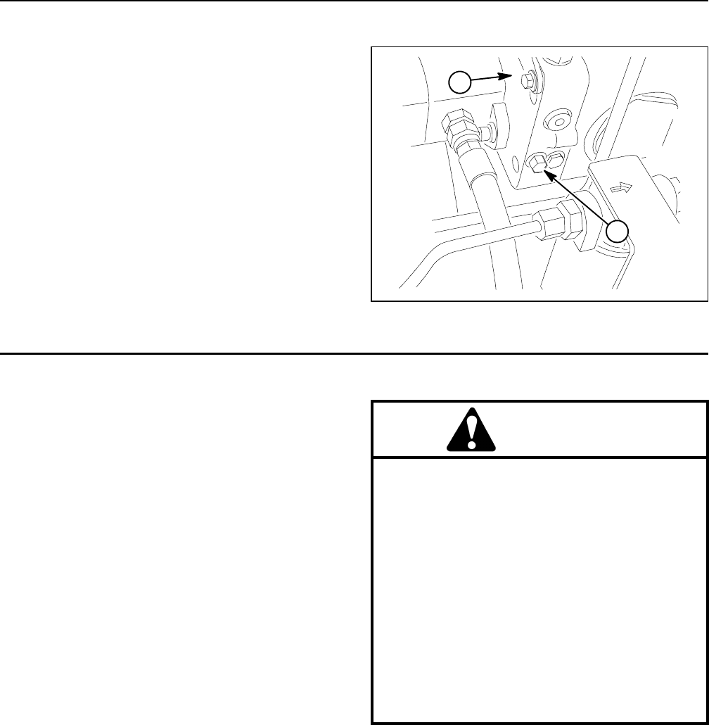
48 VDC Battery Disconnect
CAUTION
Before installing, removing or servicing compo-
nents in the 48 VDC system (e.g. cutting unit mo-
tors, motor/generator), separate the 48 VDC bat-
tery disconnect. This will prevent unexpected
operation of 48 VDC system components.
The 48 VDC battery disconnect is attached to the right
frame rail under the operator seat (Fig. 1). Unplug the
disconnect to make sure that 48 VDC components do
not operate unexpectedly. Apply dielectric grease to the
contact surfaces of the battery disconnect and plug the
battery disconnect back in after service to the 48 VDC
system is completed.
1. RH frame rail 2. 48V battery disconnect
Figure 1
2
1
FRONT
Check Hydraulic Fluid
The hydraulic system on Reelmaster 5010- H machines
is designed to operate on high quality hydraulic fluid.
The hydraulic system reservoir holds approximately 11
gallons (41.6 liters) of hydraulic fluid. Check level of hy-
draulic fluid daily. See Traction Unit Operator’s Manu-
al for fluid level checking procedure and hydraulic oil
recommendations.
Figure 2
1. Hydraulic reservoir 2. Cap with dipstick
1
2
Hydraulic
System
Reelmaster 5010- HHydraulic System Page 4 - 4
Towing Traction Unit
IMPORTANT: If towing limits are exceeded, severe
damage to the piston (traction) pump may occur.
If it becomes necessary to tow or push the machine, tow
or push at a speed below 3 mph (4.8 kph), and for a very
short distance. If the machine needs to be moved a con-
siderable distance, machine should be transported on a
trailer. The piston (traction)pumpisequippedwithaby-
pass valve that needs to be loosened for towing or push-
ing (Fig. 3). See Traction Unit Operator’s Manual for
Towing Procedures.
1. Piston (traction) pump 2. Bypass valve
Figure 3
2
1
Hydraulic Hoses
Hydraulic hoses are subject to extreme conditions such
as pressure differentials during operation and exposure
to weather, sun, chemicals, very warm storage condi-
tions or mishandling during operation and maintenance.
These conditions can cause hose damage and deterio-
ration. Some hoses are more susceptible to these
conditions than others. Inspect all machine hydraulic
hoses frequently for signs of deterioration or damage:
Hard, cracked, cut, abraded, charred, leaking or
otherwise damaged hose.
Kinked, crushed, flattened or twisted hose.
Blistered, soft, degraded or loose hose cover.
Cracked, damaged or badly corroded hose fittings.
When replacing a hydraulic hose, be sure that the hose
is straight (not twisted) before tightening the fittings.
This can be done by observing the imprint (layline) on
the hose. Use two wrenches when tightening a hose;
hold the hose straight with one wrench and tighten the
hose swivel nut onto the fitting with the second wrench
(see Hydraulic Hose and Tube Installation in this sec-
tion). If the hose has an elbow at one end, tighten the
swivel nut on that end before tightening the nut on the
straight end of the hose.
For additional hydraulic hose information, refer to Toro
Service Training Book, Hydraulic Hose Servicing (Part
Number 94813SL).
WARNING
Before disconnecting or performing any work on
hydraulic system, relieve all pressure in system
(see Relieving Hydraulic System Pressure in this
section).
Keep body and hands away from pin hole leaks or
nozzles that eject hydraulic fluid under high
pressure. Use paper or cardboard, not hands, to
search for leaks. Hydraulic fluid escaping under
pressure can have sufficient force to penetrate
the skin and cause serious injury. If fluid is in-
jected into the skin, it must be surgically re-
moved within a few hours by a doctor familiar
with this type of injury. Gangrene may result from
such an injury.
Reelmaster 5010- H Hydraulic SystemPage 4 - 5
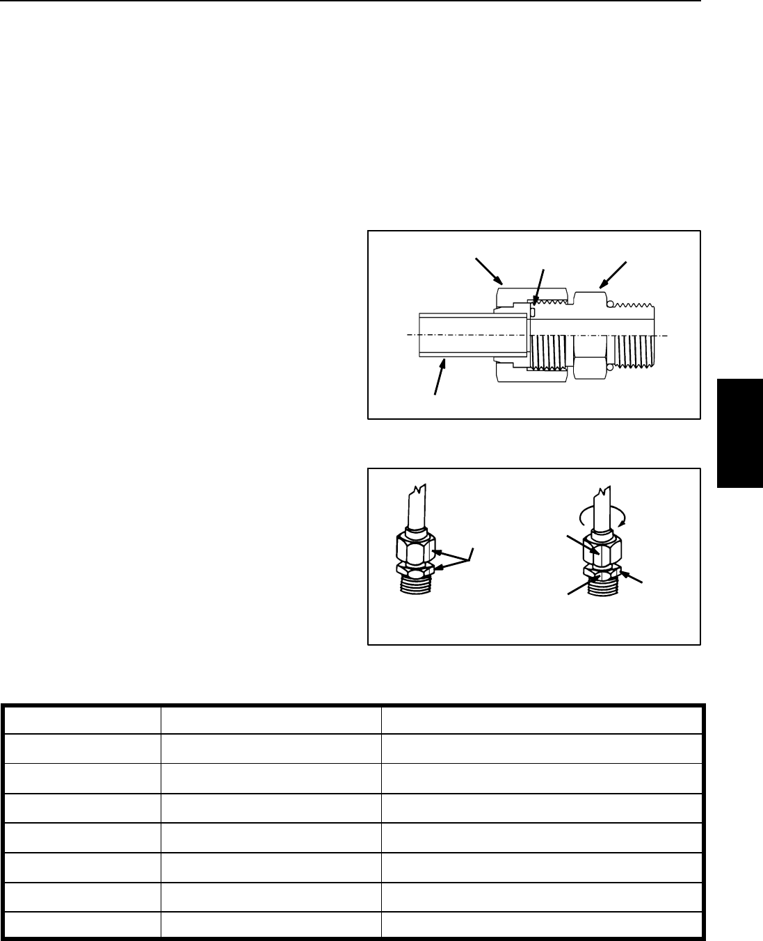
Hydraulic Hose and Tube Installation (O- Ring Face Seal Fitting)
1. Make sure threads and sealing surfaces of the hose/
tube and the fitting are free of burrs, nicks, scratches or
any foreign material.
2. As a preventative measure against leakage, it is rec-
ommended that the face seal O- ring be replaced any
time the connection is opened. Make sure the O- ring is
installed and properly seated in the fitting groove. Lightly
lubricate the O- ring with clean hydraulic oil.
3. Place the hose/tube against the fitting body so that
the flat face of the hose/tube sleeve fully contacts the O-
ring in the fitting.
4. Thread the swivel nut onto the fitting by hand. While
holding the hose/tube with a wrench, use a torque
wrench to tighten the swivel nut to the recommended
installation torque shown in Figure 6. This tightening
process will require the use of an offset wrench (e.g.
crowfoot wrench). Use of an offset wrench will affect
torque wrench calibration due to the effective length
change of the torque wrench. Tightening torque when
usingatorquewrenchwithanoffsetwrenchwillbelower
than the listed installation torque (see Using a Torque
Wrench with an Offset Wrench in the Torque Specifica-
tions section of Chapter 2 - Product Records and Main-
tenance).
5. If a torque wrench is not available or if space at the
swivel nut prevents use of a torque wrench, an alternate
method of assembly is the Flats From Wrench Resist-
ance (F.F.W.R.) method (Fig. 2).
A. Using a wrench, tighten the swivel nut onto the fit-
ting until light wrench resistance is reached (approxi-
mately 30 in- lb).
B. Mark the swivel nut and fitting body. Hold the
hose/tube with a wrench to prevent it from turning.
C. Useasecondwrenchtotightenthenuttothecor-
rect Flats From Wrench Resistance (F.F.W.R.). The
markings on the nut and fitting body will verify that the
connection has been properly tightened.
S i z e F. F. W. R .
4 (1/4 in. nominal hose or tubing) 1/2 to 3/4
6 (3/8 in.) 1/2 to 3/4
8 (1/2 in.) 1/2 to 3/4
10 (5/8 in.) 1/2 to 3/4
12 (3/4 in.) 1/3 to 1/2
16 (1 in.) 1/3 to 1/2
Figure 4
O-ring Fitting Body
Swivel Nut
Tube or Hose
Figure 5
Final
AT WRENCH RESISTANCE
Position
Mark Nut
and Fitting
Initial
Position
Extend Line
AFTER TIGHTENING
Body
Fitting Dash Size Hose/Tube Side Thread Size Installation Torque
49/16 - 18 18 to 22 ft- lb (25 to 29 N- m)
611/16 - 16 27 to 33 ft- lb (37 to 44 N- m)
813/16 - 16 37 to 47 ft- lb (51 to 63 N- m)
10 1- 14 60 to 74 ft- lb (82 to 100 N- m)
12 13/16- 12 85 to 105 ft- lb (116 to 142 N- m)
16 17/16- 12 110to136ft-lb(150to184N-m)
20 1 11/16 - 12 140 to 172 ft- lb (190 to 233 N- m)
Figure 6
Hydraulic
System
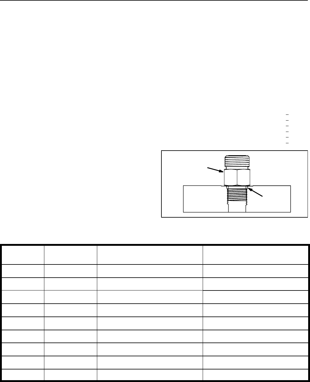
Reelmaster 5010- HHydraulic System Page 4 - 6
Hydraulic Fitting Installation (SAE Straight Thread O- Ring Fitting into Component Port)
Non- Adjustable Fitting (Fig. 7)
1. Make sure all threads and sealing surfaces of fitting
and component port are free of burrs, nicks, scratches
or any foreign material.
2. As a preventative measure against leakage, it is rec-
ommended that the O- ring be replaced any time the
connection is opened.
3. Lightly lubricate the O- ring with clean hydraulic oil.
Fitting threads should be clean with no lubricant applied.
IMPORTANT: Before installing fitting into port, de-
termine port material. If fittingistobeinstalledinto
an aluminum port, installation torque is reduced.
4. Install the fitting into the port. Then, use a torque
wrench and socket to tighten the fitting to the recom-
mended installation torque shown in Figure 8.
NOTE: Useofanoffsetwrench(e.g.crowfootwrench)
will affect torque wrench calibration due to the effective
length change of the torque wrench. Tightening torque
when using a torque wrench with an offset wrench will
be less than the recommended installation torque. See
UsingaTorqueWrenchwithanOffsetWrenchinthe
Torque Specifications section of Chapter 2 - Product
Records and Maintenance to determine necessary con-
version information.
5. If a torque wrench is not available, or if space at the
port prevents use of a torque wrench, an alternate meth-
od of assembly is the Flats From Finger Tight (F.F.F.T.)
method.
A. Install the fitting into the port and tighten it down
full length until finger tight.
B. If port material is steel, tighten the fitting to the
listed F.F.F.T. If port material is aluminum, tighten fit-
ting to 60% of listed F.F.F.T.
Si ze F. F.F. T.
4 (1/4 in. nominal hose or tubing) 1.00 + 0.25
6 (3/8 in.) 1.50 + 0.25
8 (1/2 in.) 1.50 + 0.25
10 (5/8 in.) 1.50 + 0.25
12 (3/4 in.) 1.50 + 0.25
16 (1 in.) 1.50 + 0.25
Figure 7
O-ring
Fitting
Fitting
Dash Size
Fitting Port Side
Thread Size
Installation Torque Into
Steel Port
Installation Torque Into
Aluminum Port
47/16 - 20 15 to 19 ft- lb (21 to 25 N- m) 9to11ft-lb(13to15N-m)
51/2 - 20 18 to 22 ft- lb (25 to 29 N- m) 11 to 15 ft- lb (15 to 20 N- m)
69/16 - 18 34 to 42 ft- lb (47 to 56 N- m) 20 to 26 ft- lb (28 to 35 N- m)
83/4 - 16 58 to 72 ft- lb (79 to 97 N- m) 35 to 43 ft- lb (48 to 58 N- m)
10 7/8 - 14 99 to 121 ft- lb (135 to 164 N- m) 60 to 74 ft- lb (82 to 100 N- m)
12 11/16- 12 134to164ft-lb(182to222N-m) 81to99ft-lb(110to134N-m)
14 13/16- 12 160to196ft-lb(217to265N-m) 96 to 118 ft- lb (131 to 160 N- m)
16 15/16- 12 202to248ft-lb(274to336N-m) 121to149ft-lb(165to202N-m)
20 15/8- 12 247to303ft-lb(335to410N-m) 149to183ft-lb(202to248N-m)
Figure 8
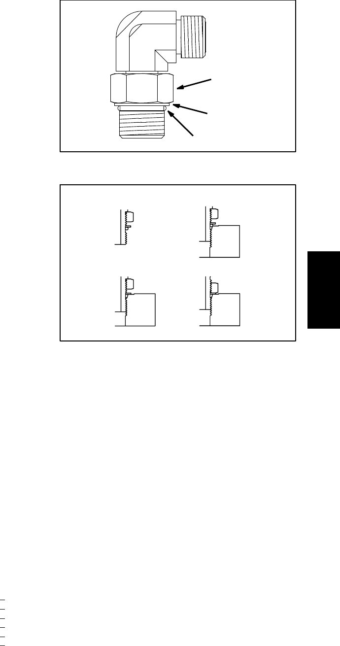
Reelmaster 5010- H Hydraulic SystemPage 4 - 7
Adjustable Fitting (Fig. 9)
1. Make sure all threads and sealing surfaces of fitting
and component port are free of burrs, nicks, scratches
or any foreign material.
2. As a preventative measure against leakage, it is rec-
ommended that the O- ring be replaced any time the
connection is opened.
3. Lightly lubricate the O- ring with clean hydraulic oil.
Fitting threads should be clean with no lubricant applied.
4. Turn back the lock nut as far as possible. Make sure
the back up washer is not loose and is pushed up as far
aspossible(Step1inFigure10).
IMPORTANT: Before installing fitting into port, de-
termine port material. If fitting is to be installed into
an aluminum port, installation torque is reduced.
5. Install the fitting into the port and tighten finger tight
until the washer contacts the face of the port (Step 2 in
Figure 10). Make sure that the fitting does not bottom in
the port during installation.
6. To put the fitting in the desired position, unscrew it by
the required amount to align fitting with incoming hose
or tube, but no more than one full turn (Step 3 in Figure
10).
7. Hold the fitting in the desired position with a wrench
and use a torque wrench to tighten the lock nut to the
recommended installation torque shown in Figure 8.
This tightening process will require the use of an offset
wrench (e.g. crowfoot wrench). Use of an offset wrench
will affect torque wrench calibration due to the effective
length change of the torque wrench. Tightening torque
when using a torque wrench with an offset wrench will
be lower than the listed installation torque (see Using a
TorqueWrenchwithanOffsetWrenchintheTorque
Specifications section of Chapter 2 - Product Records
and Maintenance).
8. If a torque wrench is not available, or if space at the
port prevents use of a torque wrench, an alternate meth-
od of assembly is the Flats From Finger Tight (F.F.F.T.)
method. Hold the fitting in the desired position with a
wrench and, if port material is steel, tighten the lock nut
withasecondwrenchtothelistedF.F.F.T.(Step4inFig-
ure 10). If port material is aluminum, tighten fitting to
60% of listed F.F.F.T.
Si ze F. F.F. T.
4 (1/4 in. nominal hose or tubing) 1.00 + 0.25
6(3/8in.) 1.50+0.25
8(1/2in.) 1.50+0.25
10 (5/8 in.) 1.50 + 0.25
12 (3/4 in.) 1.50 + 0.25
16 (1 in.) 1.50 + 0.25
Figure 9
Lock Nut
Back- up Washer
O-ring
Figure 10
Step 3Step 1
Step 2 Step 4
Hydraulic
System

Reelmaster 5010- HHydraulic System Page 4 - 8
Relieving Hydraulic System Pressure
Before disconnecting or performing any work on the hy-
draulic system, all pressure in the hydraulic system
must be relieved. Park machine on a level surface, lower
cutting units fully, stop engine and engage parking
brake.
To relieve hydraulic pressure in lift circuit, start engine
and fully lower the cutting units. Turn key switch to OFF
and remove key from the ignition switch.
To relieve hydraulic pressure in traction circuit, stop en-
gine and move traction pedal to both forward and re-
verse directions.
To relieve hydraulic pressure in steering circuit, stop en-
gine and rotate steering wheel in both directions.
Traction Circuit Component Failure
The traction circuit on Reelmaster 5010- H series ma-
chines is a closed loop system that includes the piston
(traction) pump and two (2) front wheel motors (four (4)
wheel motors on machines equipped with optional
CrossTraxTM AWD kit). If a component in the traction cir-
cuit should fail, debris and contamination from the failed
component will circulate throughout the traction circuit.
This contamination can damage other components in
the circuit so it must be removed to prevent additional
component failure.
The recommended method of removing traction circuit
contamination would be to temporarily install the Toro
high flow hydraulic filter (see Special Tools in this chap-
ter) into the circuit. This filter should be used when con-
necting hydraulic test gauges in order to test traction
circuit components or after replacing a failed traction cir-
cuit component (e.g. traction (piston) pump or wheel
motor). The filter will ensure that contaminates are re-
moved from the closed loop and thus, do not cause addi-
tional component damage.
Once the Toro high flow hydraulic filter kit has been
placed in the circuit, raise and support the machine with
all wheels off the ground. Then, operate the traction cir-
cuit to allow oil flow throughout the circuit. The filter will
remove contamination from the traction circuit during
operation. Because the Toro high flow filter is bi- direc-
tional, the traction circuit can be operated in both the for-
ward and reverse direction. The filter should be
removed from the machine after contamination has
been removed from the traction circuit. See Filtering
Closed- Loop Traction Circuit in the Service and Repairs
section of this chapter for additional information on us-
ing the Toro high flow hydraulic filter.
The alternative to using the Toro high flow hydraulic filter
kitafteratractioncircuitcomponentfailurewouldbeto
disassemble, drain and thoroughly clean all compo-
nents, hydraulic tubes and hydraulic hoses in the trac-
tion circuit. If any debris remains in the traction circuit
and the machine is operated, the debris can cause addi-
tional circuit component failure.
NOTE: The piston (traction) pump case drain could al-
low traction circuit contamination to contaminate other
hydraulic circuits on the machine.

Reelmaster 5010- H Hydraulic SystemPage 4 - 9
This page is intentionally blank.
Hydraulic
System
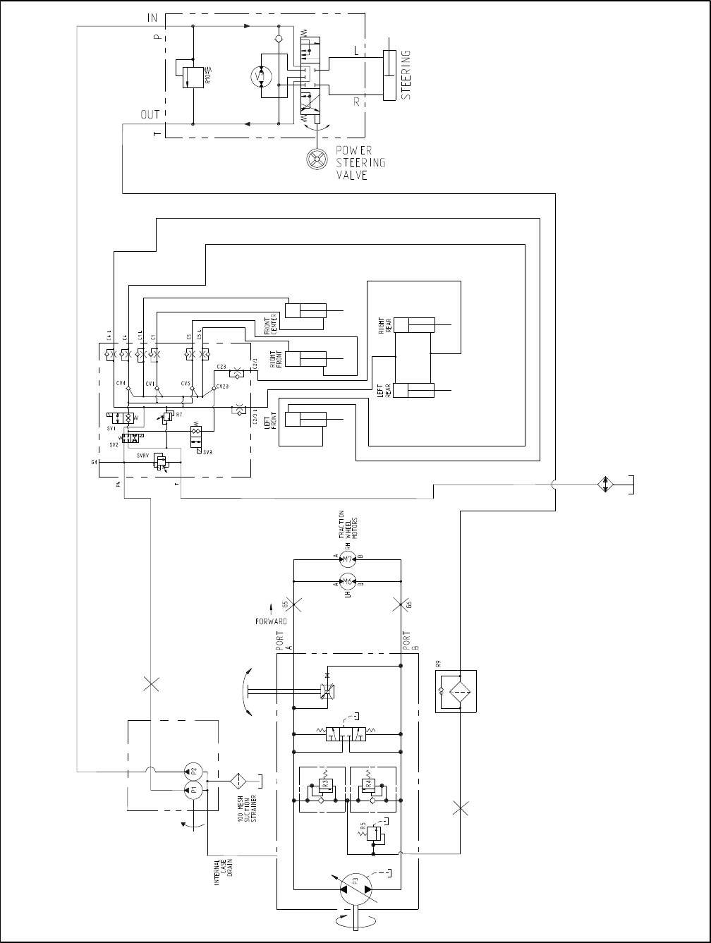
Reelmaster 5010- HHydraulic System Page 4 - 10
Hydraulic Schematic
NOTE: A larger hydraulic schematic is
included in Chapter 9 - Foldout Drawings
LIFT
CONTROL
MANIFOLD

Reelmaster 5010- H Hydraulic SystemPage 4 - 11
This page is intentionally blank.
Hydraulic
System
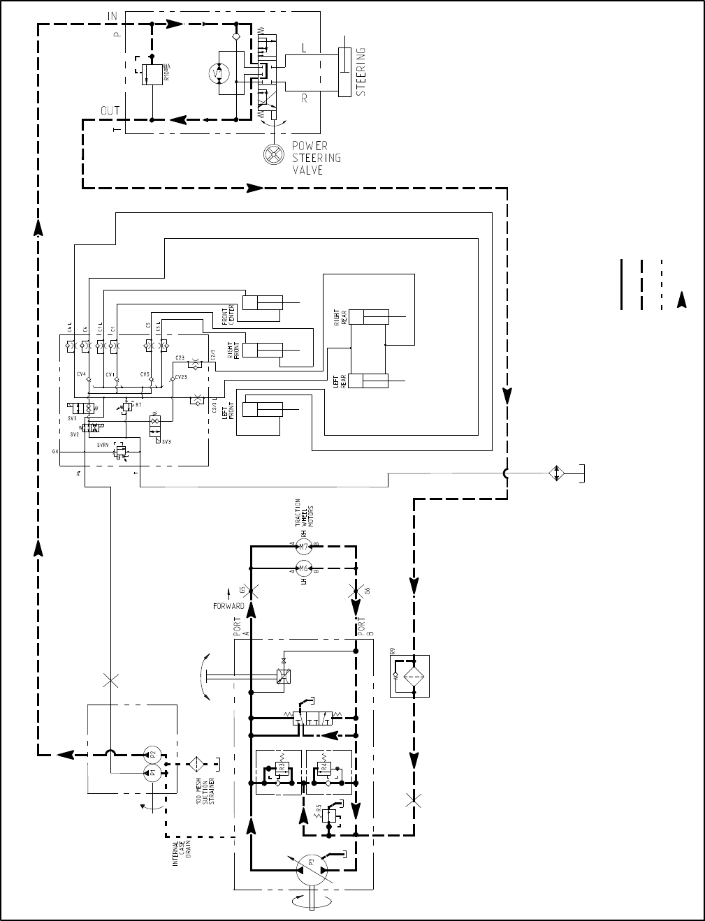
Reelmaster 5010- HHydraulic System Page 4 - 12
Hydraulic Flow Diagrams
Figure 11
Working Pressure
Low Pressure (Charge)
Return or Suction
Flow
Traction Circuit (Forward Shown)
Reelmaster 5010- H
LIFT
CONTROL
MANIFOLD
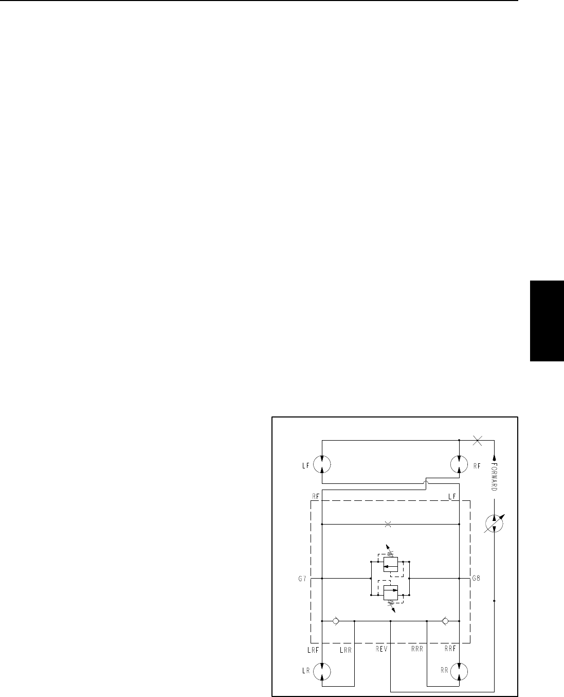
Reelmaster 5010- H Hydraulic SystemPage 4 - 13
Traction Circuit
The hydraulic traction circuit consists of a variable dis-
placement piston pump (P3) connected in a closed loop,
parallel circuit to two (2) orbital roller vane wheel motors.
The piston (traction) pump input shaft is rotated by a
drive shaft connected to the motor/generator shaft that
is driven by the engine flywheel.
Traction circuit pressure (forward and reverse) can be
measured at test ports located in the hydraulic tubes
that connect the front wheel motors.
NOTE: In high load traction situations, the 48 VDC mo-
tor/generator may automatically assist the engine to
maintain piston (traction) pump input speed.
Forward Direction (Fig. 11)
Pushing the top of the traction pedal angles the piston
(traction) pump swash plate to create a flow of oil. This
oil flow is directed to the wheel motors via hydraulic
hoses and tubes to drive the wheels in the forward direc-
tion. Forward traction pressure is limited to 3625 PSI
(250 bar) by the forward traction relief valve (R3) located
in the piston (traction) pump.
Oil flowing from the wheel motors returns to the variable
displacement pump and is continuously pumped
through the traction circuit as long as the traction pedal
is pushed.
The angle of the swash plate determines pump flow and
ultimately traction speed. When the traction pedal is de-
pressed a small amount, a small swash plate rotation re-
sults in low pump output and lower traction speed. When
the traction pedal is depressed fully, the pump swash
plate rotates fully to provide maximum pump output and
traction speed.
Gear pump section (P2) supplies oil flow for the steering
circuit and also provides a constant supply of charge oil
totheclosedlooptractioncircuit. This charge oil pro-
vides lubrication for traction circuit components and also
replenishes traction circuit oil that is lost due to internal
leakage in the traction circuit.
The hydraulic reservoir provides fluid for the gear pump
(P2) through the suction hose. Charge pump flow is di-
rected to the low pressure side of the closed loop trac-
tion circuit. Charge pressure is limited by the charge
relief valve (R5) located in the piston (traction) pump.
Thechargereliefpressureis200PSI(14bar).
The piston pump (P3) includes a flushing valve that
bleeds off a small amount of hydraulic fluid for cooling
of the closed loop traction circuit. The charge system re-
plenishes oil that is bled from the traction circuit by the
flushing valve.
Reverse Direction
The traction circuit operates essentially the same in re-
verse as it does in the forward direction. However, the
flow through the circuit is reversed. Pushing the bottom
of the traction pedal rotates the piston (traction) pump
swash plate to create a flow of oil. This oil is directed to
the wheel motors to drive the wheels in the reverse
direction. Reverse traction pressure is limited to 3625
PSI (250 bar) by the reverse traction relief valve (R4) lo-
cated in the piston (traction) pump.
Oil flowing from the wheel motors returns to the piston
(traction) pump and is continuously pumped through the
closed loop traction circuit as long as the traction pedal
is pushed.
The charge circuit and flushing valve function the same
in reverse as they do in the forward direction.
CrossTraxTM AWD (Optional)
On machines equipped with the optional CrossTraxTM
AWD kit, four (4) wheel motors are used (Fig. 12). Piston
(traction) pump flow is directed to the front tires and the
opposite rear tires to maximize traction. To reduce tire
scuffing when turning, traction system pressure is
equalized in the AWD manifold with an orifice and a bi-
directional relief valve. Check valves in the AWD man-
ifold allow the rear wheel motors to over run during tight
turns.
Figure 12
G5
CrossTrax AWD Hydraulic Schematic
TM
Hydraulic
System
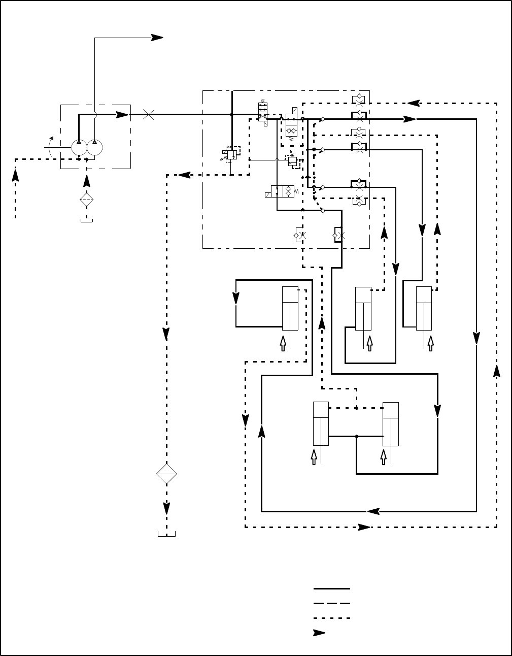
Reelmaster 5010- HHydraulic System Page 4 - 14
Figure 13
Working Pressure
Low Pressure (Charge)
Return or Suction
Flow
Lift Circuit: Raise Cutting Units
Reelmaster 5010- H
T
C4
P4
C5
C1
C2/3C2/3 L
LEFT
FRONT
RIGHT
FRONT
FRONT
CENTER
REAR
C4 L
C5 L
C1 L
REAR
LEFT RIGHT
G4
SV3
SV1
SV2
R7
SVRV
CV4
CV1
CV5
CV23
LIFT
CONTROL
MANIFOLD
100 MESH
SUCTION
STRAINER
CASE
DRAIN
P1 P2
INTERNAL
PUMP (P3)
TO STEERING
&CHARGE
CIRCUIT

Reelmaster 5010- H Hydraulic SystemPage 4 - 15
Lift Circuit: Raise Cutting Units
A two section gear pump is coupled to the piston (trac-
tion) pump. Gear pump section (P1) supplies hydraulic
flow to the lift control manifold and ultimately for the lift
cylinders. The hydraulic reservoir provides fluid for the
gear pump through the suction hose. Lift circuit pressure
is limited to 2000 PSI (138 bar) by a solenoid relief valve
(SVRV) located in the lift control manifold.
The lift control manifold includes four (4) electrically op-
erated solenoid valves. Valve (SVRV) is used to direct
gear pump flow to the lift cylinders when energized or
bypass pump flow back to the reservoir when de- ener-
gized. Valve (SV2) is used to direct oil flow to retract the
lift cylinders when energized or extend them when de-
energized. Valve (SV1) allows hydraulic flow to the front
lift cylinders when energized. Valve (SV3) allows hy-
draulic flow to the rear lift cylinders when energized.
Lift circuit pressure can be monitored at lift control man-
ifold port G4.
The TEC controller uses inputs from various machine
switches to determine when lift manifold solenoid valves
(SV1, SV2, SV3 and SVRV) are to be energized. The
TEC also provides a partial raise position of the front out-
side cutting units.
During conditions of not raising or lowering the cutting
units (joystick in the neutral (center) position), all four (4)
lift manifold solenoid valves (SV1, SV2, SV3 and SVRV)
are de- energized. Hydraulic flow from gear pump sec-
tion (P1) by- passes the lift cylinders to the oil cooler and
then to the hydraulic reservoir.
Raise Cutting Units (Fig. 13)
When the joystick is moved to the raise position, sole-
noid valve (SVRV) energizes along with solenoid valves
(SV1), (SV2) and (SV3). The energized solenoid valves
direct gear pump section P4 oil flow to the rod end of the
lift cylinders. Hydraulic pressure against the rod side of
the cylinders causes the shafts to retract, and raises the
cutting units. Fixed orifices in the lift control manifold
(C1L, C4L, C5L and C23L) control the lifting speed by
providing a restriction for the return flow from the lift cyl-
inders.
When the joystick is returned to the neutral (center)
position, the lift manifold solenoid valves are de- ener-
gized and the lift cylinders (and cutting units) are held in
the raised position. Piloted check valves in the lift control
manifold (CV1, CV4, CV5 and CV23) prevent the lift cyl-
inders (and cutting units) from dropping after they have
been raised.
Hydraulic
System
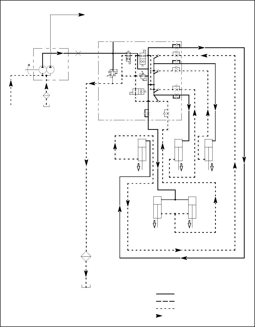
Reelmaster 5010- HHydraulic System Page 4 - 16
Figure 14
Working Pressure
Low Pressure (Charge)
Return or Suction
Flow
Lift Circuit: Lower Cutting Units
Reelmaster 5010- H
T
C4
P4
C5
C1
C2/3
C2/3 L
LEFT
FRONT
RIGHT
FRONT
FRONT
CENTER
REAR
C4 L
C5 L
C1 L
REAR
LEFT RIGHT
G4
SV3
SV1
SV2
R7
SVRV
CV4
CV1
CV5
CV23
LIFT
CONTROL
MANIFOLD
100 MESH
SUCTION
STRAINER
CASE
DRAIN
P1 P2
INTERNAL
PUMP (P3)
TO STEERING
& CHARGE
CIRCUIT
PISTON

Reelmaster 5010- H Hydraulic SystemPage 4 - 17
Lift Circuit: Lower Cutting Units
A two section gear pump is coupled to the piston (trac-
tion) pump. Gear pump section (P1) supplies hydraulic
flow to the lift control manifold and ultimately for the lift
cylinders. The hydraulic reservoir provides fluid for the
gear pump through the suction hose. Lift circuit pressure
is limited to 2000 PSI (138 bar) by a solenoid relief valve
(SVRV) located in the lift control manifold.
The lift control manifold includes four (4) electrically op-
erated solenoid valves. Valve (SVRV) is used to direct
gear pump flow to the lift cylinders when energized or
bypass pump flow back to the reservoir when de- ener-
gized. Valve (SV2) is used to direct oil flow to retract the
lift cylinders when energized or extend them when de-
energized. Valve (SV1) allows hydraulic flow to the front
lift cylinders when energized. Valve (SV3) allows hy-
draulic flow to the rear lift cylinders when energized.
Lift circuit pressure can be monitored at lift control man-
ifold port G4.
The TEC controller uses inputs from various machine
switches to determine when lift manifold solenoid valves
(SV1, SV2, SV3 and SVRV) are to be energized. The
TEC also provides a partial raise position of the front out-
side cutting units.
During conditions of not raising or lowering the cutting
units (joystick in the neutral (center) position), all four (4)
lift manifold solenoid valves (SV1, SV2, SV3 and SVRV)
are de- energized. Hydraulic flow from gear pump sec-
tion (P1) by- passes the lift cylinders to the oil cooler and
then to the hydraulic reservoir.
Lower Cutting Units (Fig. 14)
When the joystick is moved to the lower position, sole-
noid valve (SVRV) energizes along with solenoid valves
(SV1) and (SV3). Solenoid valve (SV2) is in its normally
de-energized position, and directs oil flow to the piston
end of the lift cylinders. Hydraulic pressure against the
piston side of the cylinder causes the shafts to extend,
and lower the cutting units. The piloted check valves in
the lift control manifold (CV1, CV4, CV5 and CV23) are
shifted by hydraulic pressure to allow return flow from
the extending lift cylinders. Fixed orifices in the lift con-
trol manifold (C1, C4, C5 and C23) control the lowering
speedbyprovidingarestriction for the return flow from
the lift cylinders.
Because cutting unit weight assists in extending the lift
cylinders when lowering the cutting units, less hydraulic
pressure is necessary during the cutting unit lowering
operation. Lift circuit lower relief valve (R7) allows lift cir-
cuit pressure to be limited to 500 PSI (35 bar) while low-
ering the cutting units.
NOTE: Adjustment of lift circuit lower relief valve (R7)
is not recommended.
When the joystick is returned to the neutral (center)
position, the solenoid valves are de- energized and the
lift cylinders (and cutting units) are held in the lowered
position.
Hydraulic
System
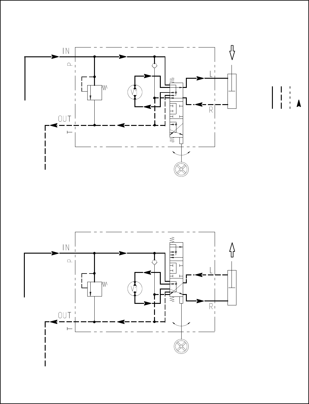
Reelmaster 5010- HHydraulic System Page 4 - 18
Figure 15
Working Pressure
Low Pressure (Charge)
Return or Suction
Flow
Steering Circuit
Reelmaster 5010- H
STEERING
CYLINDER
PISTON
MOVEMENT
STEERING
CYLINDER
PISTON
MOVEMENT
STEERING
VALVE
R10 R10
FROM PUMP (P2) FROM PUMP (P2)
TO TRACTION
CHARGE CIRCUIT
TO TRACTION
CHARGE CIRCUIT
LEFT TURN
RIGHT TURN
CONTROL
STEERING
VALVE
CONTROL

Reelmaster 5010- H Hydraulic SystemPage 4 - 19
Steering Circuit
A two section gear pump is coupled to the piston (trac-
tion) pump. Gear pump section P2 supplies hydraulic
flow to the steering control valve and for the traction
charge circuit. The hydraulic reservoir provides fluid for
the gear pump through the suction hose. Steering circuit
pressure is limited to 1000 PSI (70 bar) by a relief valve
(R10) located in the steering control.
With the steering wheel in the neutral position and the
engine running, flow enters the steering control valve at
the P port and goes through the steering control spool
valve, by- passing the rotary meter (V1) and steering
cylinder. Flow leaves the control valve through the T port
to the hydraulic oil filter and traction charge circuit.
Left Turn (Fig. 15)
When a left turn is made with the engine running, the
turning of the steering wheel positions the steering con-
trol spool valve so that flow is directed through the bot-
tom of the spool. Flow entering the steering control valve
at the P port goes through the spool and is routed to two
places. First, most of the flow through the valve is by-
passed out the T port back to the hydraulic oil filter and
traction charge circuit. Second, the remainder of the
flow is drawn through the rotary meter (V1) and out the
L port. Pressure contracts the steering cylinder piston
for a left turn. The rotary meter ensures that the oil flow
to the steering cylinder is proportional to the amount of
turning on the steering wheel. Fluid leaving the steering
cylinder flows back through the steering control spool
valve and then out of the steering control valve through
theTportandtotheoilfilterandtractionchargecircuit.
The steering control valve returns to the neutral position
when turning is completed.
Right Turn (Fig. 15)
When a right turn is made with the engine running, the
turning of the steering wheel positions the steering con-
trol spool valve so that flow is directed through the top
of the spool. Flow entering the steering control valve at
the P port goes through the spool and is routed to two
places. As in a left turn, most of the flow through the
valve is by- passed out the T port back to the hydraulic
oil filter and traction charge circuit. Also like a left turn,
the remainder of the flow is drawn through rotary meter
(V1) but goes out port R. Pressure extends the steering
cylinder piston for a right turn. The rotary meter ensures
that the oil flow to the steering cylinder is proportional to
the amount of the turning on the steering wheel. Fluid
leaving the steering cylinder flows back through the
steering control spool valve then through the T port and
to the oil filter and traction charge circuit.
The steering control valve returns to the neutral position
when turning is completed.
Hydraulic
System
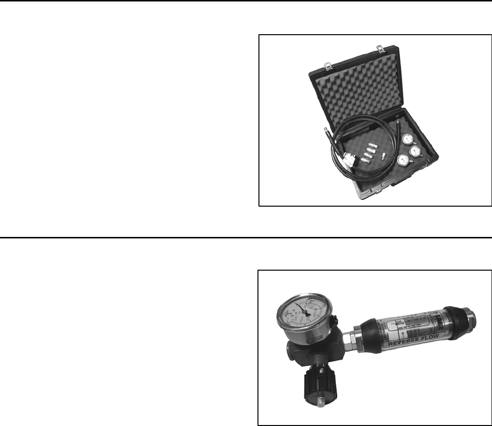
Reelmaster 5010- HHydraulic System Page 4 - 20
Special Tools
Order these special tools from your Toro Distributor.
Hydraulic Pressure Test Kit
Toro Part Number: TOR47009
Use to take various pressure readings for diagnostic
tests. Quick disconnect fittings provided attach directly
to mating fittings on machine test ports without tools. A
high pressure hose is provided for remote readings.
Contains one each: 1000 PSI (70 bar), 5000 PSI (350
bar) and 10000 PSI (700 bar) gauges. Use gauges as
recommended in the Testing section of this chapter.
Figure 16
15 GPM Hydraulic Tester Kit (Pressure and Flow)
Toro Part Number: TOR214678
Use to test hydraulic circuits and components for flow
and pressure capacities as recommended in the Testing
section of this chapter. This tester includes the following:
1. INLET HOSE: Hose connected from the system cir-
cuit to the inlet side of the hydraulic tester.
2. LOAD VALVE: A simulated working load is created
in the circuit by turning the valve to restrict flow.
3. PRESSURE GAUGE: Glycerine filled 0 to 5000 PSI
gauge to provide operating circuit pressure.
4. FLOW METER: This meter measures actual oil flow
in the operating circuit with a gauge rated from 1 to 15
GPM(5to55LPM).
5. OUTLET HOSE: A hose from the outlet side of the
hydraulic tester connects to the hydraulic system circuit.
6. FITTINGS: An assortment of hydraulic fittings are in-
cluded with this kit.
Figure 17
Reelmaster 5010- H Hydraulic SystemPage 4 - 21
40 GPM Hydraulic Tester (Pressure and Flow)
Toro Part Number: AT40002
Use to test hydraulic circuits and components for flow
and pressure capacities as recommended in the Testing
section of this chapter. This tester includes the following:
1. LOAD VALVE: A simulated working load is created
in the circuit by turning the valve to restrict flow.
2. PRESSURE GAUGE: Glycerine filled 0 to 5000 PSI
gauge to provide operating circuit pressure.
3. FLOW METER: This meter measures actual oil flow
intheoperatingcircuitwithagaugeratedfrom4to40
GPM (20 to 150 LPM).
NOTE: This tester does not include hydraulic hoses
(see Hydraulic Hose Kit TOR6007 below).
Figure 18
Hydraulic Hose Kit
Toro Part Number: TOR6007
This kit includes hydraulic fittings and hoses needed to
connect 40 GPM hydraulic tester (AT40002) or high flow
hydraulic filter kit (TOR6011) to machine hydraulic trac-
tion system components.
Figure 19
Hydraulic
System
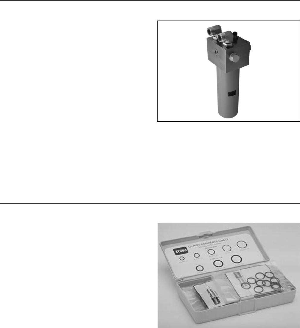
Reelmaster 5010- HHydraulic System Page 4 - 22
High Flow Hydraulic Filter Kit
Toro Part Number: TOR6011
The high flow hydraulic filter kit is designed with large
flow (40 GPM/150 LPM) and high pressure (5000
PSI/345 bar) capabilities. This kit provides for bi- direc-
tional filtration which prevents filtered debris from being
allowed back into the circuit regardless of flow direction.
If a component failure occurs in the closed loop traction
circuit, contamination from the failed part will remain in
the circuit until removed. When connecting hydraulic
test gauges in order to test traction circuit components
or after replacing a failed traction circuit component (e.g.
piston pump or wheel motor), the high flow hydraulic fil-
ter can be installed in the traction circuit. The filter will
ensure that contaminates are removed from the closed
loop and thus, do not cause additional component dam-
age.
NOTE: This kit does not include hydraulic hoses (see
Hydraulic Hose Kit TOR6007 above).
NOTE: Replacement filter element is Toro part number
TOR6012. Filter element cannister tightening torque is
25 ft- lb (34 N- m).
Figure 20
O-Ring Kit
Toro Part Number: 117- 2727
The O- ring kit includes O- rings in a variety of sizes for
face seal and port seal hydraulic connections. It is rec-
ommended that O- rings be replaced whenever a hy-
draulic connection is loosened.
Figure 21
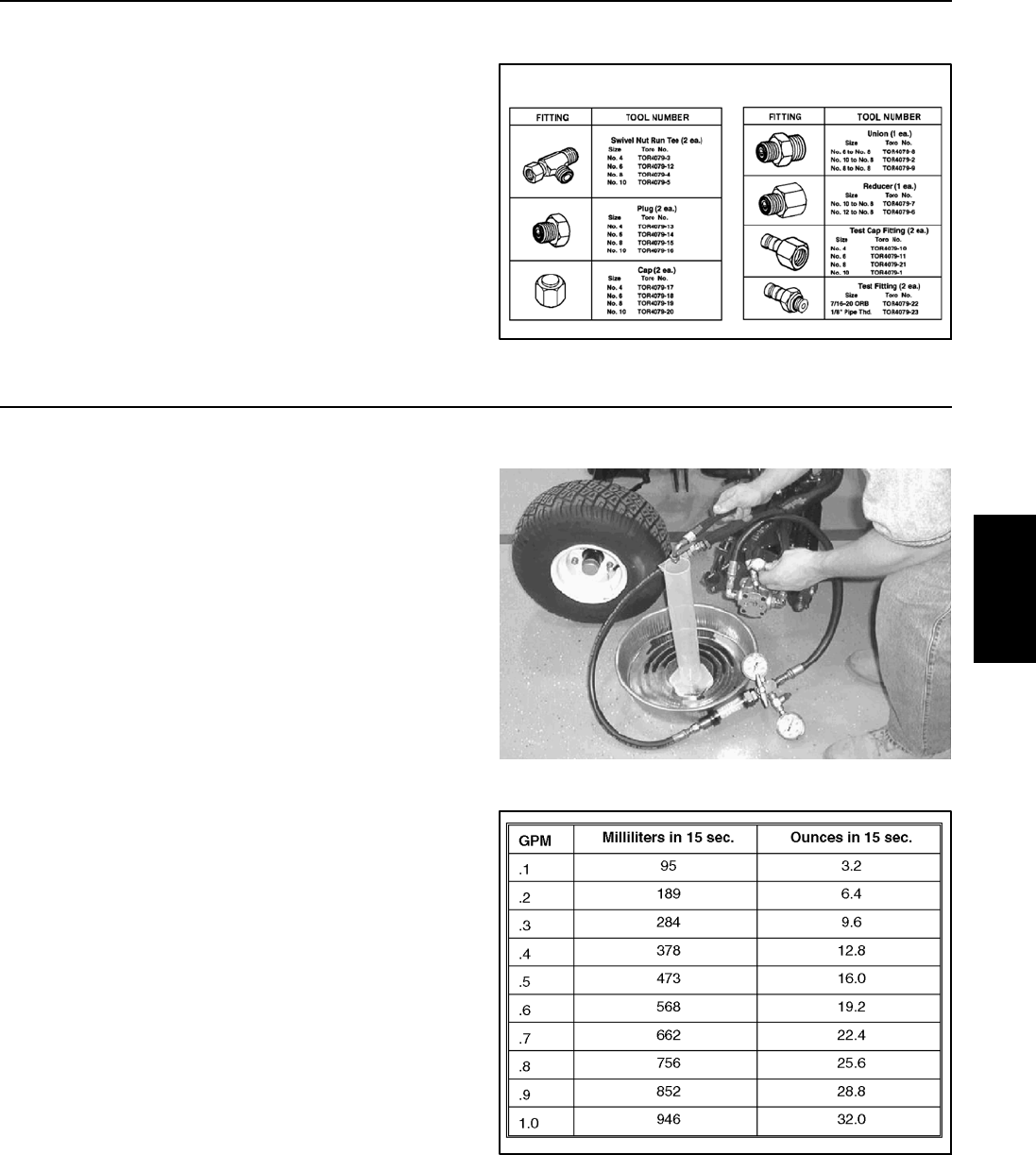
Reelmaster 5010- H Hydraulic SystemPage 4 - 23
Hydraulic Test Fitting Kit
Toro Part Number: TOR4079
This kit includes a variety of O- ring face seal fittings to
enable the connection of test gauges into the system.
The kit includes: tee’s, unions, reducers, plugs, caps
and male test fittings.
Figure 22
TORO TEST FITTING KIT (TOR4079)
Measuring Container
Toro Part Number: TOR4077
Use this graduated container for doing hydraulic motor
efficiency testing (motors with case drain lines only).
Measure efficiency of a hydraulic motor by restricting the
outlet flow from the motor and measuring leakage from
the case drain line while the motor is pressurized by the
hydraulic system.
The table in Figure 24 provides gallons per minute
(GPM) conversion for measured milliliter or ounce motor
case drain leakage.
Figure 23
Figure 24
Hydraulic
System
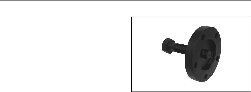
Reelmaster 5010- HHydraulic System Page 4 - 24
Wheel Hub Puller
The wheel hub puller allows safe removal of the wheel
hub from the wheel motor shaft.
Toro Part Number: TOR6004
Figure 25

Reelmaster 5010- H Hydraulic SystemPage 4 - 25
Troubleshooting
The cause of an improperly functioning hydraulic sys-
tem is best diagnosed with the use of proper testing
equipment and a thorough understanding of the com-
plete hydraulic system.
A hydraulic system with an excessive increase in heat
or noise has a potential for failure. Should either of these
conditions be noticed, immediately stop the machine,
turn off the engine, locate the cause of the trouble and
correct it before allowing the machine to be used again.
Continued use of an improperly functioning hydraulic
system could lead to extensive hydraulic component
damage.
The charts that follow contain information to assist in
troubleshooting. There may possibly be more than one
cause for a machine malfunction.
Refer to the Testing section of this chapter for precau-
tions and specific hydraulic test procedures.
General Hydraulic System Problems
Problem Possible Cause
Hydraulic oil leaks from machine Fitting(s), hose(s) or tube(s) is (are) loose or damaged.
O- ring(s) or seal(s) is (are) missing or damaged.
Foaming hydraulic fluid Oil level in hydraulic reservoir is low.
Hydraulic system has wrong kind of oil.
Pump suction line has an air leak.
Hydraulic system operates hot Traction system pressure is high due to excessive load or brake
dragging or binding.
Oil level in hydraulic reservoir is low.
Hydraulic oil is contaminated or too light.
Engine speed is too low.
Engine fan is not operating properly.
Oil cooler is damaged or plugged. Air flow through oil cooler is ob-
structed.
Hydraulic oil filter is plugged.
Charge pressure is low.
Piston (traction) pump bypass valve is open or faulty.
Piston (traction) pump check valve is not seating or is damaged.
Wheel motor(s) and/or piston (traction) pump are worn or damaged
(NOTE: If a traction circuit component has internal wear or dam-
age, it is possible that other traction components are also dam-
aged).
Hydraulic
System

Reelmaster 5010- HHydraulic System Page 4 - 26
Traction Circuit Problems
Problem Possible Cause
Neutral is difficult to find or unit oper-
ates in one direction only
Traction control linkage is misadjusted, disconnected, binding or
damaged.
Piston (traction) pump check relief valve is not seating or is dam-
aged (NOTE: Piston (traction) pump check relief valves for forward
and reverse are identical and can be reversed for testing pur-
poses).
Piston (traction) pump is worn or damaged.
Traction response is sluggish Charge pressure is low.
Hydraulic oil is very cold.
Parking brake is dragging or binding.
Piston (traction) pump bypass valve is not seated.
Flushing valve in piston (traction) pump is not seating or is dam-
aged.
Piston (traction) pump charge relief valve is not seating or is dam-
aged.
Piston (traction) pump check relief valve is not seating or is dam-
aged (NOTE: Check relief valves for forward and reverse are iden-
tical and can be reversed for testing purposes).
Piston (traction) pump is worn or damaged.
No traction in either direction Parking brake is dragging or binding.
Traction control linkage is misadjusted, disconnected, binding or
damaged.
Oil level in hydraulic reservoir is low (other hydraulic systems af-
fected as well).
Piston (traction) pump bypass valve is loosened.
Flushing valve in piston (traction) pump is not seating or is dam-
aged.
Piston (traction) pump check valve is not seating or is damaged.
Charge pressure is low.
Wheel motor(s) and/or piston (traction) pump are worn or damaged
(NOTE: If a traction circuit component has internal wear or dam-
age, it is possible that other traction components are also dam-
aged).
Single wheel motor turns while un-
loaded, but slows down or stops
when load is applied
Wheel motor is worn or damaged.
(NOTE: If a traction circuit component has internal wear or dam-
age, it is possible that other traction components are also dam-
aged)

Reelmaster 5010- H Hydraulic SystemPage 4 - 27
Traction Circuit Problems (Continued)
Problem Possible Cause
Wheel motor will not turn Brakes are binding.
Wheel motor is worn or damaged.
(NOTE: If a traction circuit component has internal wear or dam-
age, it is possible that other traction components are also dam-
aged)
Lift Circuit Problems
Problem Possible Cause
Single cutting unit lifts slowly or not
at all
Affected cutting unit has excessive debris buildup.
Lift arm or lift cylinder for the affected cutting unit is binding.
Pilot piston in lift control manifold for the affected cutting unit is
stuck or damaged.
Lift cylinder for the affected cutting unit leaks internally.
Flow control orifice in lift control manifold for the affected cutting
unit is plugged or damaged.
Cutting units raise, but will not re-
main in the raised position
(NOTE: Lift cylinders and control
manifold check valves cannot pro-
vide an absolutely perfect seal. The
cutting units will eventually lower if
left in the raised position)
Lift cylinder leaks internally.
Lift control manifold check valve(s) (CV1, CV4, CV5 and CV23)
and solenoid valve (SV1 and SV3) leaks.
Pilot piston in lift control manifold is stuck and is preventing check
valve from seating.
None of the cutting units will raise or
lower
Oil level in hydraulic reservoir is low (other hydraulic systems af-
fected as well).
Cutting units are in the backlap position (NOTE: Operator advisory
should be displayed on InfoCenter Display).
Solenoid valve SVRV on lift control manifold is faulty.
An electrical problem exists that prevents SVRV solenoid coil on
the lift control manifold from being energized (see Troubleshooting
in Chapter 5 - Electrical System).
Gear pump section for lift/lower function (P1) is worn or damaged.
Hydraulic
System

Reelmaster 5010- HHydraulic System Page 4 - 28
Lift Circuit Problems (Continued)
Problem Possible Cause
None of the front cutting units will
raise or lower but the rear cutting
units will raise and lower
Solenoid valve SV1 on lift control manifold is faulty.
An electrical problem exists that prevents SV1 solenoid coil on the
lift control manifold from being energized (see Troubleshooting in
Chapter 5 - Electrical System).
Neither of the rear cutting units will
raise or lower but the front cutting
units will raise and lower
Solenoid valve SV3 on lift control manifold is faulty.
An electrical problem exists that prevents SV3 solenoid coil on the
lift control manifold from being energized (see Troubleshooting in
Chapter 5 - Electrical System).
Flow control orifice in lift control manifold for the rear cutting units
(C23 or C23L) is plugged or damaged.
Check valve in lift control manifold for the rear cutting units (CV23)
is stuck or damaged.
Single cutting unit lowers very slowly
or not at all
Lift arm or lift cylinder for the affected cutting unit is binding.
Lift cylinder for the affected cutting unit is damaged.
Flow control orifice in lift control manifold for the affected cutting
unit is plugged or damaged.
Check valve in lift control manifold (CV1, CV4, CV5 and CV23) is
stuck or damaged.
Steering Circuit Problems
Problem Possible Cause
Steering inoperative or sluggish Steering components (e.g. tie rods, steering cylinder ends) are
worn or binding.
Steering cylinder is binding.
Oil level in hydraulic reservoir is low (other hydraulic systems af-
fected as well).
Steering relief valve (R10) in steering control valve is stuck or dam-
aged.
Steering cylinder leaks internally.
Steering control valve is worn or damaged.
Internal gear pump drive coupler is damaged.
Gear pump section (P2) is worn or damaged (NOTE: A worn or
damaged gear pump section (P2) will also affect the traction
(charge) circuit).

Reelmaster 5010- H Hydraulic SystemPage 4 - 29
This page is intentionally blank.
Hydraulic
System
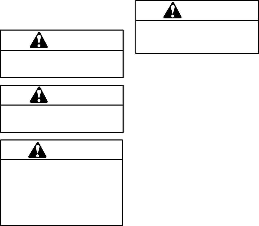
Reelmaster 5010- HHydraulic System Page 4 - 30
Testing
The most effective method for isolating problems in the
hydraulic system is by using hydraulic test equipment
such as pressure gauges and flow meters in the circuits
during various operational checks (see the Special
Tools section in this chapter).
Before Performing Hydraulic Tests
IMPORTANT: All obvious areas such as oil supply,
oil filter, binding linkages, loose fasteners or im-
proper adjustments must be checked before as-
suming that a hydraulic component is the source of
a hydraulic system problem.
Precautions for Hydraulic Testing
CAUTION
Failure to use gauges with expected pressure
(psi) rating as listed in test procedures could re-
sult in damage to the gauge and possible person-
al injury from leaking hot oil.
CAUTION
All testing should be performed by two (2)
people. One person should be in the seat to oper-
ate the machine and the other should monitor
test equipment and record test results.
WARNING
Keep body and hands away from pin hole leaks
or nozzles that eject hydraulic fluid under high
pressure. Do not use hands to search for leaks;
use paper or cardboard. Hydraulic fluid escap-
ing under pressure can have sufficient force to
penetrate the skin and cause serious injury. If
fluid is injected into the skin, it must be surgical-
ly removed within a few hours by a doctor famil-
iar with this type of injury. Gangrene may result
from such an injury.
1. Clean machine thoroughly before disconnecting or
disassembling any hydraulic components. Always keep
in mind the need for cleanliness when working on hy-
draulic equipment. Contamination can cause excessive
wear or binding of hydraulic components.
2. Review all test steps before starting the test proce-
dure.
3. Before testing, check all control linkages for improp-
er adjustment, binding or broken parts.
4. All hydraulic tests should be made with the hydraulic
oil at normal operating temperature. Operate the ma-
chine under load for at least ten (10) minutes before per-
forming hydraulic tests.
WARNING
Before disconnecting or performing any work
on the hydraulic system, all pressure in the sys-
tem must be relieved. See Relieving Hydraulic
System Pressure in the General Information sec-
tion.
5. Put metal caps or plugs on any hydraulic lines left
open or exposed during testing or component removal.
6. When using hydraulic tester (pressure and flow), the
inlet and the outlet hoses must be properly connected
and not reversed to prevent damage to the hydraulic
tester or components.
7. Install hydraulic fittings finger tight and far enough to
make sure that they are not cross- threaded before tight-
eningthemwithawrench.
8. Position tester hoses to prevent rotating machine
parts from contacting and damaging the hoses or tester.
9. After connecting test equipment, check oil level in
the hydraulic reservoir to make sure that oil level is cor-
rect.
10.When using hydraulic tester (pressure and flow),
open tester load valve completely before starting engine
to minimize the possibility of damaging components.
11. The engine must be in good operating condition. Use
a phototac when performing a hydraulic test. Engine
speed can affect the accuracy of the tester readings.
Check actual speed of the pump when performing hy-
draulic flow tests.
12.After hydraulic test procedures have been com-
pleted, check oil level in the hydraulic reservoir to make
sure that oil level is correct.

Reelmaster 5010- H Hydraulic SystemPage 4 - 31
Which Hydraulic Tests Are Necessary?
Before beginning any hydraulic test, identify if the prob-
lem is related to the traction circuit, lift circuit or steering
circuit. Once the faulty system has been identified, per-
form tests that relate to that circuit.
1. If a traction circuit problem exists, consider perform-
ing one or more of the following tests: Traction Circuit
Relief Valve (R3) and (R4) Pressure, Traction Circuit
Charge Pressure, Gear Pump (P2) Flow, Front Wheel
Motor Efficiency and/or Piston (Traction) Pump Flow
Tests.
2. If a lift circuit problem exists, consider performing
one or more of the following tests: Lift Relief Valve
(SVRV) Pressure, Gear Pump (P1) Flow and/or Lift Cyl-
inder Internal Leakage Tests.
3. If a steering circuit problem exists, consider perform-
ing one or more of the following tests: Steering Relief
Valve (R10) Pressure, Steering Cylinder Internal Leak-
age and/or Gear Pump (P2) Flow Tests.
Hydraulic
System
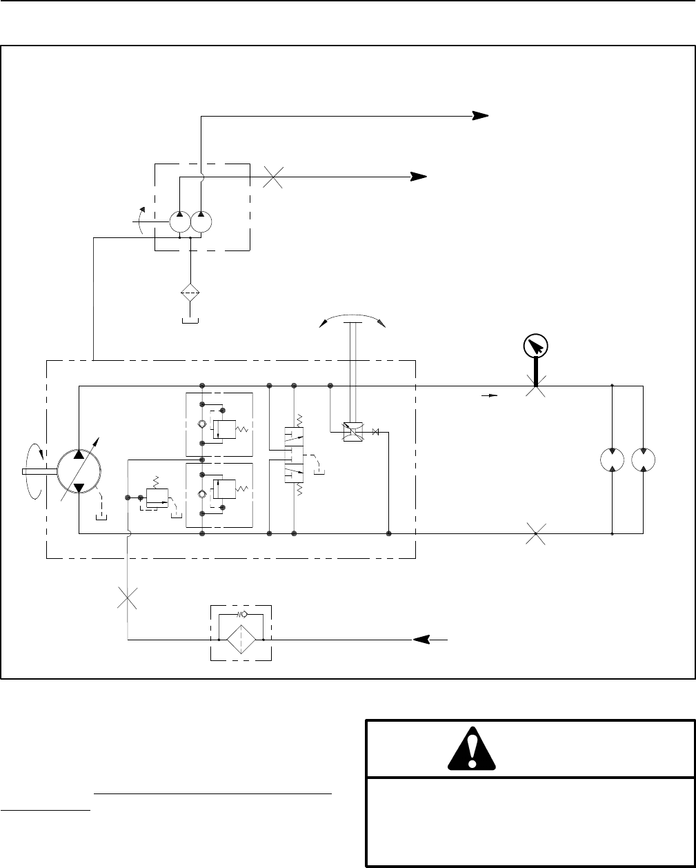
Reelmaster 5010- HHydraulic System Page 4 - 32
Traction Circuit Relief Valve (R3) and (R4) Pressure Test
Figure 26
FORWARD
M7
M6
FROM STEERING CONTROL VALVE
R9
INTERNAL
CASE
DRAIN
TRACTION
WHEEL
MOTORS
G5
G6
B
R5 R4
R3
A
B
A
B
LH RH
A
P3
TO LIFT CONTROL MANIFOLD
TO STEERING CONTROL VALVE AND CHARGE CIRCUIT
PRESSURE
GAUGE
FORWARD (R3) RELIEF
VALVE TEST SHOWN
100 MESH
SUCTION
STRAINER
P1 P2
TO LIFT CONTROL MANIFOLD
TO STEERING CONTROL VALVE AND CHARGE CIRCUIT
Thetractioncircuitreliefpressuretestshouldbeper-
formed to make sure that forward and reverse traction
circuit relief pressures are correct.
Procedure for Traction Circuit Relief Valve (R3) and
(R4) Pressure Test
1. Drive machine to an open area. Park machine on a
level surface with the cutting units lowered and disen-
gaged. Make sure engine is off. Apply the parking brake.
2. Read Precautions For Hydraulic Testing at the be-
ginning of this section.
CAUTION
Before opening hydraulic system, operate all hy-
draulic controls to relieve system pressure and
avoid injury from pressurized hydraulic oil. See
Relieving Hydraulic System Pressure in the Gen-
eral Information section of this chapter.
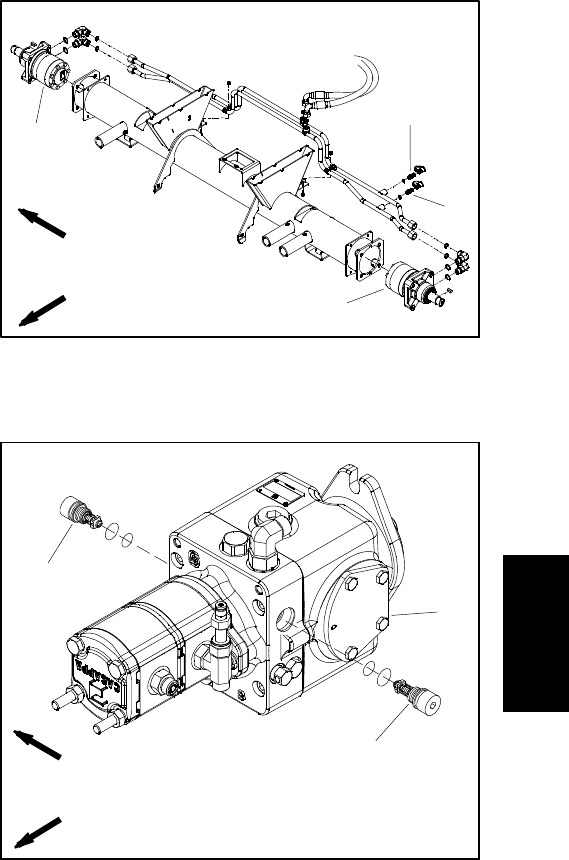
Reelmaster 5010- H Hydraulic SystemPage 4 - 33
NOTE: If machine is equipped with optional
CrossTraxTM AWD, reverse relief pressure test ports
are located on CrossTraxTM hydraulic manifold.
3. Thoroughly clean traction circuit test port on hydrau-
lic tube for direction to be checked (Fig. 27). Connect a
5000 PSI (350 bar) pressure gauge to test port.
4. After installing tester, start engine and run at low idle
speed. Check for any hydraulic leakage from test con-
nections and correct before proceeding with test.
5. Make sure hydraulic oil is at normal operating tem-
perature by operating the machine under load for
approximately ten (10) minutes.
6. Sit on seat and increase engine speed to high idle
speed (3000 RPM).
7. Apply brakes and slowly depress the traction pedal
in the direction to be tested (forward or reverse). While
pushing traction pedal down, carefully watch the pres-
sure gauge needle. As the traction relief valve lifts, the
gauge needle will momentarily stop. Traction system
pressure as the relief valve opens should be:
Approximately 3625 PSI (250 bar) in both forward
(R3) and reverse (R4)
NOTE: If traction pedal continues to be pressed after
the relief valve has opened, system pressure may in-
crease higher than relief pressure.
8. When relief pressure has been identified, release
traction pedal, stop engine and record test results.
NOTE: Forward (R3) and reverse (R4) relief valves are
identical. Relief valves can be switched in piston (trac-
tion)pumptohelpinidentifyingafaultyreliefvalve.
9. If traction pressure problem occurs in one direction
only, interchange the relief valves in the piston (traction)
pump (Fig. 28) to see if the problem changes to the other
direction. Clean or replace valves as necessary. These
cartridge type valves are factory set, and are not adjust-
able. If traction relief pressure is low and relief valves are
in good condition, piston (traction) pump and/or wheel
motors should be suspected of wear and inefficiency.
10.After testing is completed, make sure that engine is
stopped and then relieve hydraulic system pressure
(See Relieving Hydraulic System Pressure in the Gen-
eral Information section of this chapter). Remove pres-
sure gauge from machine and install dust cap to test
port.
1. RH wheel motor
2. LH wheel motor
3. Forward test port
4. Reverse test port
Figure 27
FRONT
RIGHT
2WD MACHINE SHOWN
2
3
4
1
1. Piston (traction) pump
2. Reverse relief valve (R4)
3. Forward relief valve (R3)
Figure 28
2
3
1
FRONT
RIGHT
Hydraulic
System
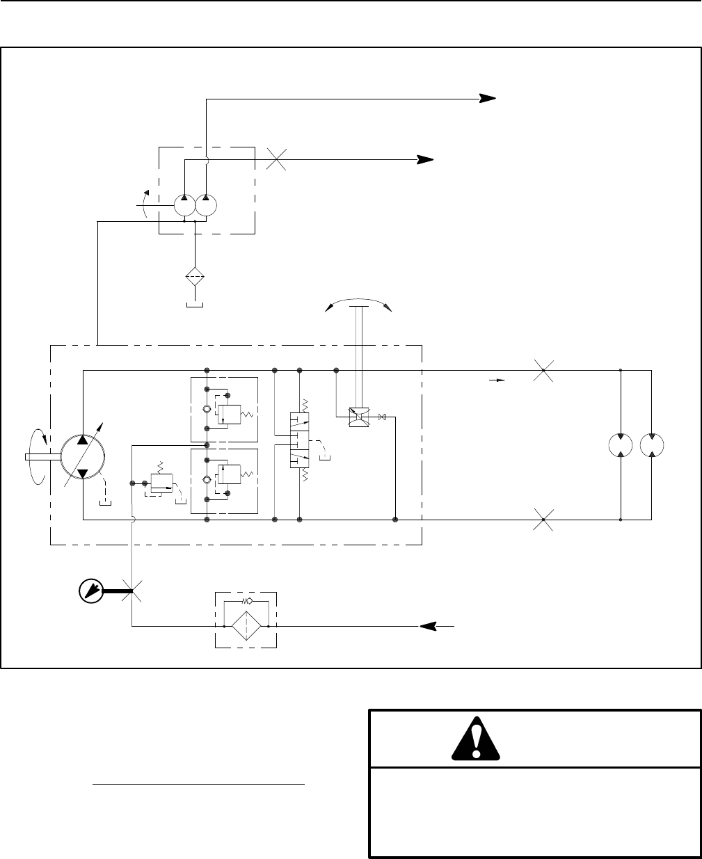
Reelmaster 5010- HHydraulic System Page 4 - 34
Traction Circuit Charge Pressure Test
Figure 29
FORWARD
M7
M6
FROM STEERING CONTROL VALVE
R9
INTERNAL
CASE
DRAIN
TRACTION
WHEEL
MOTORS
G5
G6
B
R5 R4
R3
A
B
A
B
LH RH
A
P3
TO LIFT CONTROL MANIFOLD
TO STEERING CONTROL VALVE AND CHARGE CIRCUIT
PRESSURE
GAUGE
100 MESH
SUCTION
STRAINER
P1 P2
TO LIFT CONTROL MANIFOLD
TO STEERING CONTROL VALVE AND CHARGE CIRCUIT
The traction circuit charge pressure test should be per-
formed to make sure that the traction charge circuit is
functioning correctly.
Procedure for Traction Circuit Charge Pressure Test
1. Parkmachineonalevelsurfacewiththecuttingunits
lowered and disengaged. Make sure engine is off. Apply
the parking brake.
2. Read Precautions For Hydraulic Testing in this sec-
tion.
3. Raise and support operator seat to allow access to
hydraulic pump assembly.
CAUTION
Before opening hydraulic system, operate all hy-
draulic controls to relieve system pressure and
avoid injury from pressurized hydraulic oil. See
Relieving Hydraulic System Pressure in the Gen-
eral Information section of this chapter.
4. Thoroughly clean test port on hydraulic tube be-
tween piston (traction) pump and oil filter (Fig. 30). Con-
nect a 1000 PSI (70 bar) pressure gauge to test port.
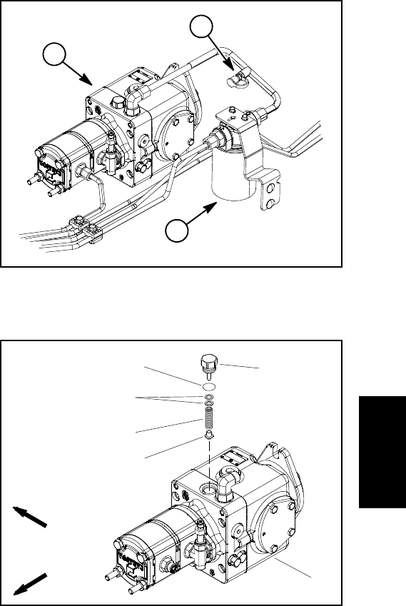
Reelmaster 5010- H Hydraulic SystemPage 4 - 35
5. Start engine and run at idle speed. Check for any hy-
draulic leakage from test connections and correct be-
fore proceeding with test.
6. Make sure hydraulic oil is at normal operating tem-
perature by operating the machine under load for
approximately ten (10) minutes.
7. Make sure that traction pedal is in neutral, the steer-
ing wheel is stationary and parking brake is engaged.
8. Increase engine speed to high idle speed (3000
RPM) and monitor pressure gauge to determine no load
charge pressure. Record test results.
GAUGE READING TO BE approximately 200 to
250 PSI (13.8 to 17.2 bar)
9. Next, determine charge pressure under traction load
by operating the machine in a direct forward and reverse
direction (not steering). Make sure that engine is run-
ning at full speed (3000 RPM). Apply the brakes and
press the traction pedal in the forward direction and then
to reverse while monitoring the pressure gauge. Stop
engine and record test results.
GAUGE READING TO BE approximately 150 to
250 PSI (13.8 to 17.2 bar)
10.Compare measured charge pressure from step 8
with pressure from step 9:
A. If charge pressure is good under no load (step 8),
but drops below specification when under traction
load (step 9), the piston (traction) pump should be
suspected of wear and inefficiency. When the pump
is worn or damaged, the charge system is not able to
replenish lost traction circuit oil due to excessive
leakage in the worn pump.
B. If there is no charge pressure, or pressure is low,
check for restriction in gear pump intake line. Inspect
charge relief valve and valve seat in the piston (trac-
tion) pump (see Piston (Traction) Pump Service in
the Service and Repairs section of this chapter).
Also, consider a worn or damaged gear pump sec-
tion (P2) (see Gear Pump Flow Test in this section).
NOTE: If gear pump (P2) is worn or damaged, both
charge circuit and steering circuit will be affected.
11.After charge pressure testing is completed, make
sure that engine is not running and then relieve hydrau-
lic system pressure (See Relieving Hydraulic System
Pressure in the General Information section of this
chapter). Remove pressure gauge from test port and in-
stall dust cap to test port.
12.Lower and secure operator seat.
1. Piston (traction) pump
2. Oil filter
3. Test fitting
Figure 30
1
3
2
1. Piston (traction) pump
2. Plug
3. O- ring
4. Shim kit
5. Spring
6. Charge relief poppet
Figure 31
FRONT
RIGHT
2
3
4
1
5
6
Hydraulic
System
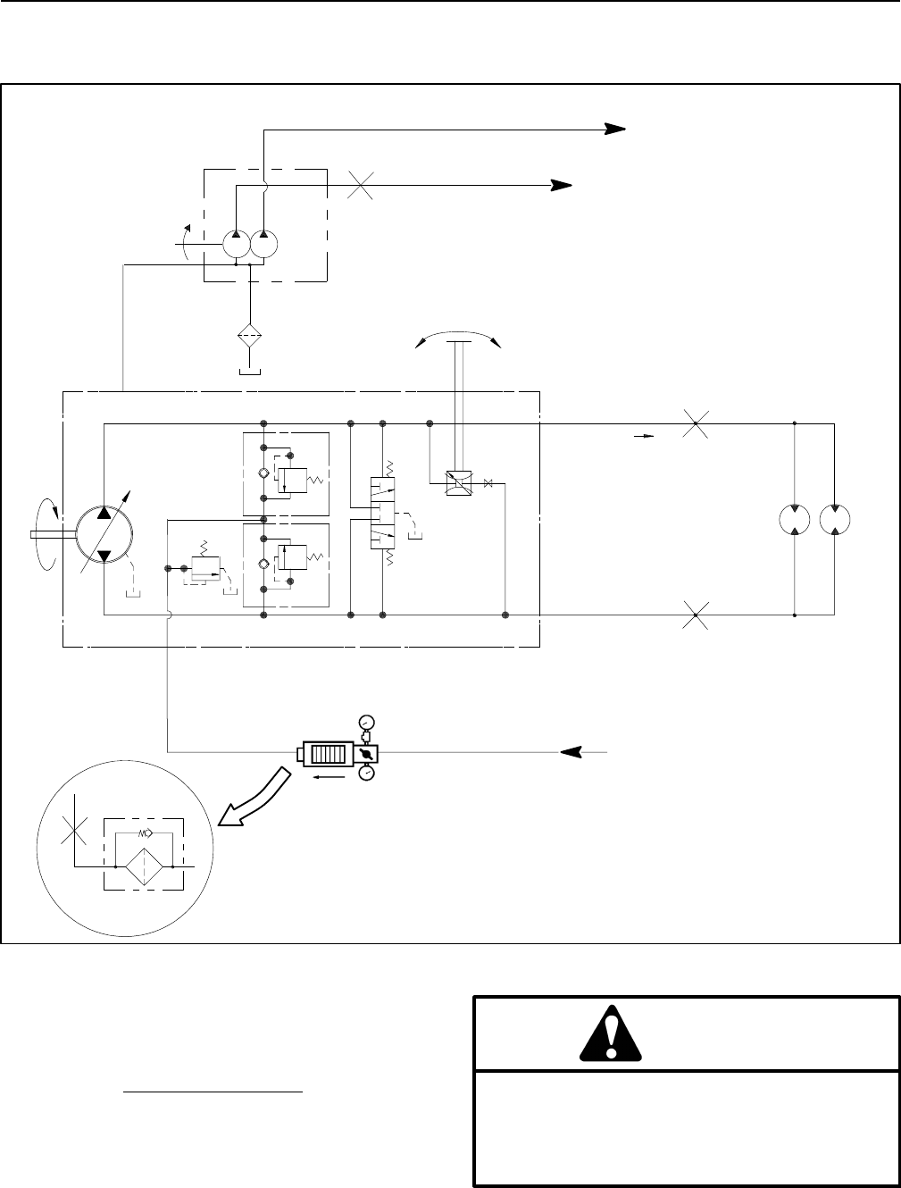
Reelmaster 5010- HHydraulic System Page 4 - 36
Gear Pump (P2) Flow Test
(Using Tester with Pressure Gauges and Flow Meter)
Figure 32
FORWARD
M7
M6
FROM STEERING CONTROL VALVE
R9
INTERNAL
CASE
DRAIN
TRACTION
WHEEL
MOTORS
G5
G6
B
R5 R4
R3
A
B
A
B
LH RH
A
P3
TESTER
OIL FILTER
REMOVED
AND TUBE
TO LIFT CONTROL MANIFOLD
TO STEERING CONTROL VALVE AND CHARGE CIRCUIT
100 MESH
SUCTION
STRAINER
P1 P2
The gear pump (P2) flow test should be performed to
make sure that the traction charge circuit and steering
circuit have adequate hydraulic flow.
Procedure for Gear Pump (P2) Flow Test
1. Parkmachineonalevelsurfacewiththecuttingunits
lowered and disengaged. Make sure engine is off. Apply
the parking brake.
2. Read Precautions For Hydraulic Testing in this sec-
tion.
CAUTION
Before opening hydraulic system, operate all hy-
draulic controls to relieve system pressure and
avoid injury from pressurized hydraulic oil. See
Relieving Hydraulic System Pressure in the Gen-
eral Information section of this chapter.
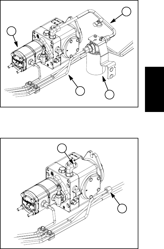
Reelmaster 5010- H Hydraulic SystemPage 4 - 37
3. Raise and prop operator seat to allow access to hy-
draulic pump assembly.
4. Thoroughly clean the ends of the hydraulic tubes
connected to the oil filter and piston pump inlets (Fig.
33). Disconnect hydraulic tubes from oil filter inlet and
piston pump inlet. Remove two (2) flange head screws
that secure oil filter adapter to frame. Remove oil filter
assembly and hydraulic tube from machine.
IMPORTANT: Make sure that the oil flow indicator
arrow on the flow meter is showing that the oil will
flow from the hydraulic tube, through the tester and
into the piston (traction) pump.
5. Install tester with pressure gauge and flow meter in
place of the removed oil filter assembly and hydraulic
tube (Fig. 34). Connect tester inlet hose to the hydraulic
tube. Connect the tester outlet hose to the piston (trac-
tion) pump fitting. Make sure the flow control valve on
tester is fully open.
6. Make sure that the traction pedal is in neutral, the
steering wheel is stationary and the parking brake is en-
gaged.
7. Start engine and run at idle speed. Check for any hy-
draulic leakage from test connections and correct be-
fore proceeding with test.
8. Make sure hydraulic oil is at normal operating tem-
perature by operating the machine under load for
approximately ten (10) minutes.
9. Increase engine speed to high idle speed (3000
RPM). Use InfoCenter Display to verify that engine
speed is correct.
IMPORTANT: The gear pump is a positive displace-
ment type. If pump flow is completely restricted or
stopped, damage to the pump, tester or other com-
ponents could occur.
10.While watching tester pressure gauge, slowly close
the tester flow control valve until 800PSI(55bar)is ob-
tained on gauge.
FLOW TESTER READING TO BE: Apumpingood
condition should have a flow of approximately 4.7
GPM (17.8 LPM) at 800 PSI (55 bar).
11. Open the tester flow control valve, stop engine and
record test results.
12.If flow is less than 4GPM(15.1LPM)or a pressure
of 800 PSI (55 bar) cannot be obtained, consider that a
gear pump problem exists. Check for restriction in pump
intake line. If intake is not restricted, remove gear pump
and repair or replace pump as necessary (see Hydraulic
Pump Assembly and Gear Pump Service in the Service
and Repairs section of this chapter).
NOTE: If the flow from gear pump (P2) is low, the opera-
tion of both the charge circuit and the steering circuit will
be affected.
13.After testing is completed, make sure that engine is
stopped, then relieve hydraulic system pressure (See
Relieving Hydraulic System Pressure in the General In-
formation section of this chapter). Remove hydraulic
tester from hydraulic tube and pump fitting. Install oil fil-
ter assembly and then connect removed hydraulic tube
to oil filter and piston pump fitting.
14.Lower and secure operator seat.
1. Hydraulic tube
2. Oil filter
3. Hydraulic tube
4. Gear Pump (P2)
Figure 33
3
2
4
1
1. Tester inlet connection 2. Tester outlet connection
Figure 34
2
1
Hydraulic
System
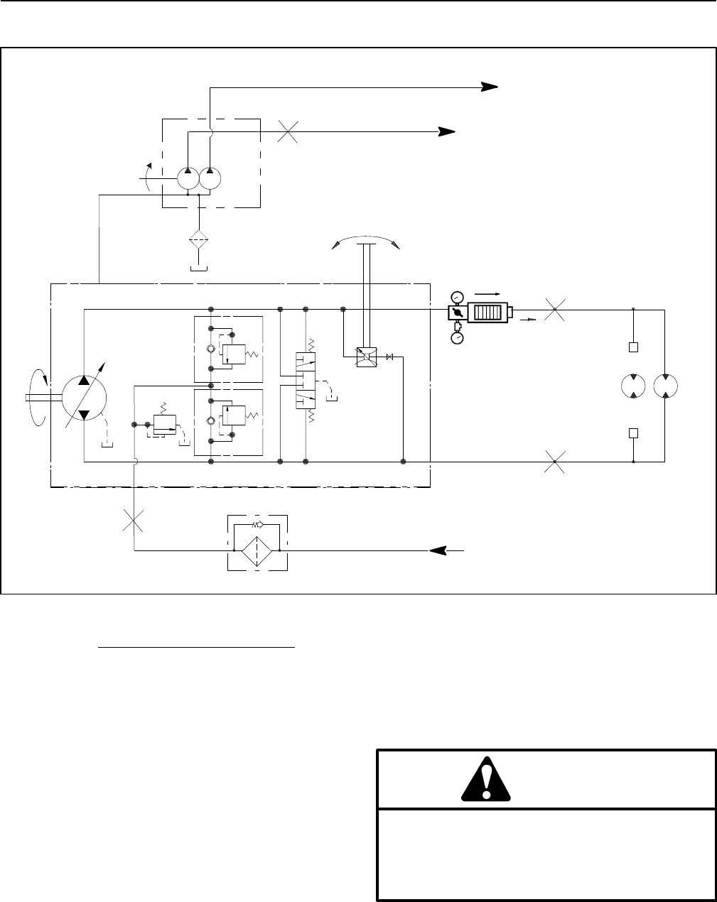
Reelmaster 5010- HHydraulic System Page 4 - 38
Front Wheel Motor Efficiency Test
Figure 35
FORWARD
M7
M6
FROM STEERING CONTROL VALVE
R9
INTERNAL
CASE
DRAIN
TRACTION
WHEEL
MOTORS
G5
G6
B
R5 R4
R3
A
B
A
B
LH RH
A
P3
TESTER
CAP
CAP
RH FRONT WHEEL
MOTOR EFFICIENCY
TEST SHOWN
TO LIFT CONTROL MANIFOLD
TO STEERING CONTROL VALVE AND CHARGE CIRCUIT
100 MESH
SUCTION
STRAINER
P1 P2
Procedure for Front Wheel Motor Efficiency Test
NOTE: Over a period of time, a wheel motor can wear
internally. A worn motor may by- pass oil causing the
motor to be less efficient. Eventually, enough oil loss will
cause the wheel motor to stall under heavy load condi-
tions. Continued operation with a worn, inefficient motor
can generate excessive heat, cause damage to seals
and other components in the hydraulic system and af-
fect overall machine performance.
IMPORTANT: Refer to Traction Circuit Component
Failure in the General Information section for infor-
mation regarding the importance of removing con-
tamination from the traction circuit.
NOTE: This test procedure includes steps to test both
front wheel efficiency together before testing individual
wheel motors.
1. Make sure that traction pedal is adjusted to the neu-
tral position (see Traction Unit Operator’s Manual).
2. Drive machine to an open area. Park machine on a
level surface with the cutting units lowered and disen-
gaged. Make sure engine is off.
3. Read Precautions For Hydraulic Testing in this sec-
tion.
CAUTION
Before opening hydraulic system, operate all hy-
draulic controls to relieve system pressure and
avoid injury from pressurized hydraulic oil. See
Relieving Hydraulic System Pressure in the Gen-
eral Information section of this chapter.
4. Attach a heavy chain to the rear of the machine frame
and an immovable object to prevent the machine from
moving during testing.
5. Chock front wheels to prevent wheel rotation.
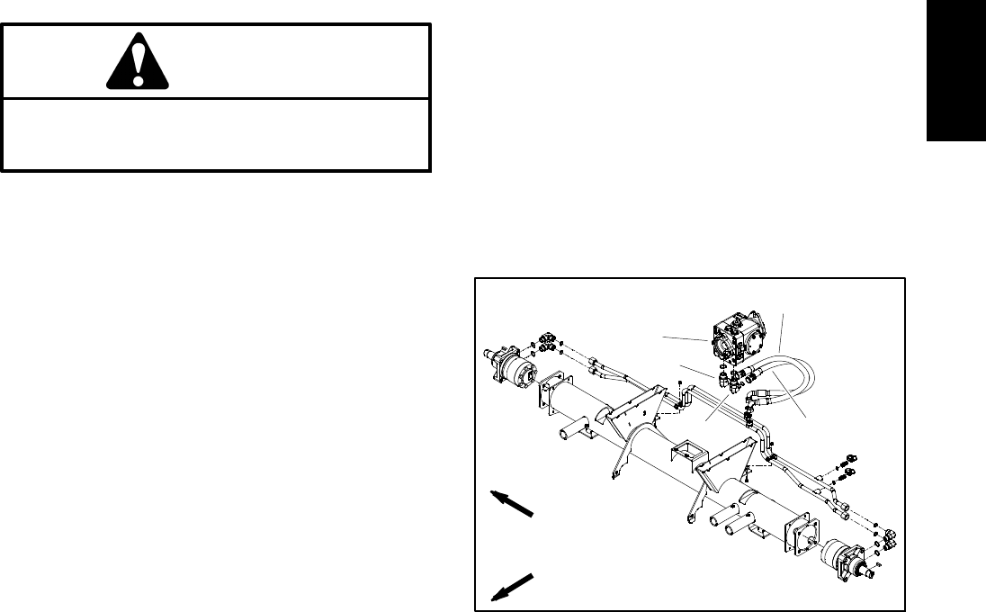
Reelmaster 5010- H Hydraulic SystemPage 4 - 39
NOTE: If machine is equipped with optional
CrossTraxTM AWD, jack up and support the rear wheels
off the ground to allow flow through the rear wheel mo-
tors.
6. Thoroughly clean junction of hydraulic hose and
right side elbow fitting on bottom of piston (traction)
pump (Fig. 36). Disconnect hose from piston (traction)
pump fitting.
IMPORTANT: Make sure that the oil flow indicator
arrow on the flow meter is showing that the oil will
flow from the pump, through the tester and into the
hydraulic hose.
7. Install tester with pressure gauges and flow meter in
series with the piston (traction) pump and the discon-
nected hose. Make sure the tester flow control valve
is fully open.
8. Start engine and increase engine speed to high idle
speed (3000 RPM). Make sure hydraulic oil is at normal
operating temperature by operating the machine under
load for approximately ten (10) minutes.
CAUTION
Use extreme caution when performing test. The
front tires on the ground will be trying to move
the machine forward.
9. Fully apply the brakes to prevent the front wheels
from rotating and slowly push traction pedal in forward
direction until 1000 PSI is displayed on the tester pres-
sure gauge.
10.Combined front wheel motor internal leakage will be
shown on flow meter in GPM (LPM).
11.Release traction pedal, release brake pedal, shut
engine off, rotate both front wheels and retest. Testing
of wheel motor leakage in three (3) different wheel posi-
tions will provide the most accurate test results. Record
measured front wheel motor internal leakage for all
three (3) wheel positions.
12.If combined leakage for the front wheel motors is
less than 1.5 GPM (5.7 LPM), consider that the front
wheel motors are in good condition. If combined leak-
age for the front wheel motors is more than 1.5 GPM
(5.7 LPM), one or both of the motors may be faulty. Indi-
vidual front wheel motor testing is necessary.
13.To test individual front wheel motors:
A. Remove front wheel from wheel motor that is not
being tested. Remove wheel shield to allow access
to hydraulic tubes and fittings on wheel motor. Re-
move fasteners that secure front hydraulic tube r-
clamps to frame.
B. On the front wheel motor that is not being tested,
thoroughly clean junction of both hydraulic tubes and
wheel motor fittings. Disconnect both hydraulic lines
from wheel motor that is not being tested. Install a
steel cap on disconnected hydraulic lines and wheel
motor fittings.
C. Use the procedure described in steps 8 to 10
above to identify individual front wheel motor leak-
age. Individual motor internal leakage will be shown
on flow meter in GPM (LPM). Flow should be less
than 1.5 GPM (5.7 LPM) for the tested wheel motor.
If leakage for the tested motor is more than 1.5 GPM
(5.7 LPM), the tested motor is faulty.
D. If other front wheel motor requires testing, com-
plete steps A, B and C for remaining wheel motor.
14.After testing is completed, stop engine and then re-
lieve hydraulic system pressure (See Relieving Hydrau-
lic System Pressure in the General Information section
of this chapter). Disconnect tester from hydraulic fitting
and hose. Connect hose to pump elbow fitting. Remove
caps from hydraulic tubes and reconnect tubes to wheel
motor. Secure hydraulic tubes to machine with r- clamps
and removed fasteners. Install wheel shield and
wheel(s) (see Wheels in the Service and Repairs sec-
tion of Chapter 6 - Chassis).
1. Piston (traction) pump
2. RH elbow fitting
3. Hyd hose (forward)
4. LH elbow fitting
5. Hyd hose (reverse)
Figure 36
FRONT
RIGHT
2WD MACHINE SHOWN
1
4
3
2
5
Hydraulic
System
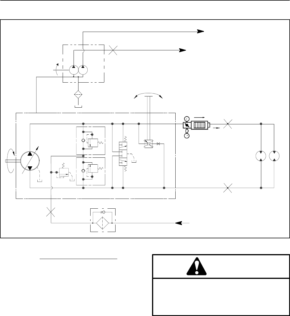
Reelmaster 5010- HHydraulic System Page 4 - 40
Piston (Traction) Pump Flow Test (Using Tester with Flow Meter and Pressure Gauge)
Figure 37
FORWARD
M7
M6
FROM STEERING CONTROL VALVE
R9
INTERNAL
CASE
DRAIN
TRACTION
WHEEL
MOTORS
G5
G6
B
R5 R4
R3
A
B
A
B
LH RH
A
P3
TESTER
TO LIFT CONTROL MANIFOLD
TO STEERING CONTROL VALVE AND CHARGE CIRCUIT
100 MESH
SUCTION
STRAINER
P1 P2
Procedure for Piston (Traction) Pump Flow Test
This test measures piston (traction) pump output (flow).
During this test, pump load is created at the flow meter
using the adjustable load valve on the tester.
IMPORTANT: Traction circuit flow for your Reel-
master is approximately 30 GPM (113.5 LPM). Use 40
GPM Hydraulic Tester #AT40002 (pressure and flow)
for this test (see Special Tools in this chapter).
1. Parkmachineonalevelsurfacewiththecuttingunits
lowered and disengaged. Make sure engine is off. Apply
the parking brake. Make sure mow speed limiter is in the
transport position to allow full movement of traction ped-
al.
2. Read Precautions For Hydraulic Testing in this sec-
tion.
CAUTION
Before opening hydraulic system, operate all hy-
draulic controls to relieve system pressure and
avoid injury from pressurized hydraulic oil. See
Relieving Hydraulic System Pressure in the Gen-
eral Information section of this chapter.
3. Make sure that traction pedal is adjusted to the neu-
tral position. Also, ensure that piston (traction) pump is
at full stroke when traction pedal is pushed into fully for-
ward position.
4. Raise and support machine so all wheels are off the
ground (see Jacking Instructions in Chapter 1 - Safety).
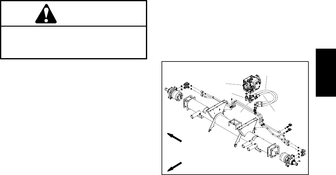
Reelmaster 5010- H Hydraulic SystemPage 4 - 41
5. Thoroughly clean junction of hydraulic hose and
right side fitting on bottom of piston (traction) pump (Fig.
38). Disconnect hose from right side pump fitting.
IMPORTANT: Make sure that the oil flow indicator
arrow on the flow meter is showing that the oil will
flow from the pump, through the tester and into the
disconnected hydraulic hose.
6. Install tester with pressure gauge and flow meter in
series between piston pump fitting and disconnected
hosetoallowflowfrompistonpumptotester.Usehy-
draulic hose kit (see Special Tools in this chapter) to con-
nect tester to machine. Make sure that fitting and hose
connections are properly tightened. Also, make sure the
flow control valve on tester is fully open.
CAUTION
Drive wheels will be off the ground and rotating
during this test. Make sure machine is supported
so it will not move and accidentally fall to prevent
injuring anyone near the machine.
7. Start engine and run at idle speed. Check for any hy-
draulic leakage from tester and hose connections. Cor-
rect any leaks before proceeding.
8. Increase engine speed to high idle speed (3000
RPM). Make sure hydraulic oil is at normal operating
temperature by operating the machine under load for
approximately ten (10) minutes. Make sure the hydrau-
lic reservoir is full.
9. Slowly push traction pedal to fully forward position.
Keep pedal fully depressed in the forward position dur-
ing the flow test.
10.Have second person watch pressure gauge on test-
er carefully while slowly closing the tester flow control
valve until 1000 PSI (69 bar) is obtained. Verify with the
InfoCenter Display that the engine speed is still 3000
RPM.
11. Observe flow gauge. For a piston pump in good con-
dition, flow indication should be approximately 26 GPM
(98 LPM).
12.Openflowcontrolvalveontester,releasetraction
pedal to the neutral position and shut off engine. Record
test results.
13.If measured flow is less than 23 GPM (87 LPM),con-
sider the following:
A. The piston (traction) pump swash plate is not be-
ing rotated fully (e.g. traction pedal linkage may need
adjustment, mow speed limiter is not in the transport
position).
B. The piston (traction) pump needs to be repaired
or replaced as necessary.
C. Make necessary repairs before performing addi-
tional hydraulic tests on the traction system.
14.When testing is complete, disconnect tester and
hose kit from pump fitting and machine hydraulic hose.
Reconnect hose to pump fitting.
1. Piston (traction) pump
2. RH elbow fitting
3. Hyd hose (forward)
4. LH elbow fitting
5. Hyd hose (reverse)
Figure 38
FRONT
RIGHT
2WD MACHINE SHOWN
1
4
3
2
5
Hydraulic
System
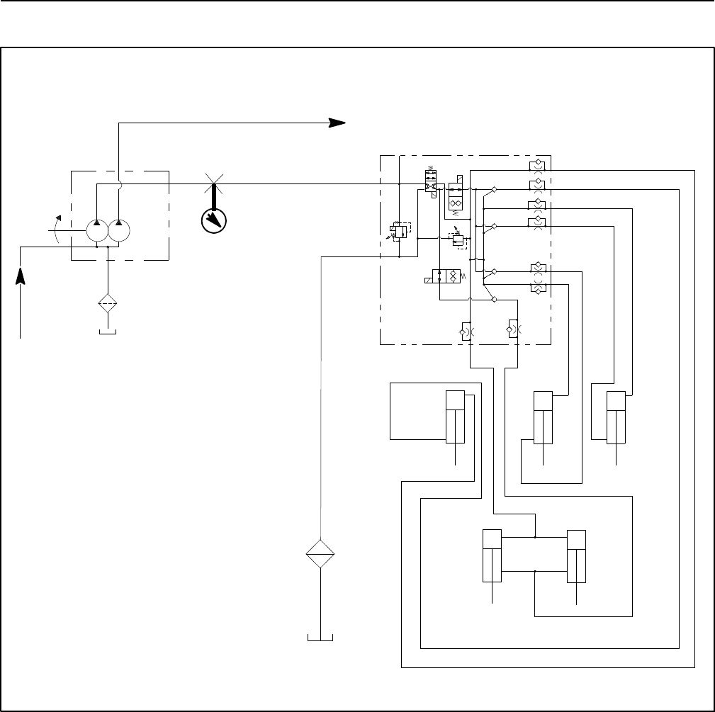
Reelmaster 5010- HHydraulic System Page 4 - 42
Lift Relief Valve (SVRV) Pressure Test
Figure 39
T
C4
P4
C5
C1
C2/3
C2/3 L
LEFT
FRONT
RIGHT
FRONT
FRONT
CENTER
REAR
C4 L
C5 L
C1 L
REAR
LEFT RIGHT
INTERNAL
CASE
DRAIN
G4
SV3
SV1
SV2
R7
SVRV
CV4
CV1
CV5
CV23
PUMP (P3)
PRESSURE
GAUGE
LIFT
CONTROL
MANIFOLD
TO STEERING CONTROL VALVE AND CHARGE CIRCUIT
100 MESH
SUCTION
STRAINER
P1 P2
PISTON
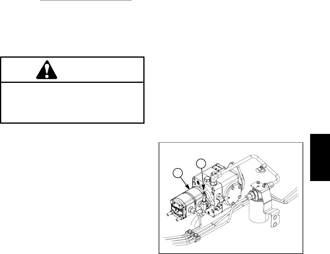
Reelmaster 5010- H Hydraulic SystemPage 4 - 43
The lift relief valve (SVRV) pressure test should be per-
formed to make sure that the lift circuit relief pressure is
correct.
Procedure for Lift Relief Valve (SVRV) Pressure Test
1. Parkmachineonalevelsurfacewiththecuttingunits
lowered and disengaged. Make sure engine is off. Apply
the parking brake.
2. Read Precautions For Hydraulic Testing in this sec-
tion.
CAUTION
Before opening hydraulic system, operate all hy-
draulic controls to relieve system pressure and
avoid injury from pressurized hydraulic oil. See
Relieving Hydraulic System Pressure in the Gen-
eral Information section of this chapter.
3. Raise and support operator seat to allow access to
hydraulic pump assembly.
4. Thoroughly clean test port attached to tee fitting on
1st gear pump section (P1) (Fig. 40). Connect a 5000
PSI (350 bar) pressure gauge to test port.
5. After installing pressure gauge to test port, start en-
gine and run at low idle speed. Check for any hydraulic
leakage from test connections and correct before pro-
ceeding with test.
6. Increase engine speed to high idle speed (3000
RPM). Make sure hydraulic oil is at normal operating
temperature by operating the machine under load for
approximately ten (10) minutes.
IMPORTANT: Do not allow circuit pressure to ex-
ceed 2500 PSI (172 bar).
IMPORTANT: While performing this test, hold lower
mow/raise lever in the raise position only long
enough to get a system pressure reading. Holding
the lever in raise for an extended period may dam-
age system components.
7. Make sure that reel engage/disengage switch is OFF
and then pull lower mow/raise lever rearward (raise po-
sition) to pressurize lift circuit. While holding lever rear-
ward, watch pressure gauge carefully. As the cutting
units raise fully and the lift relief valve lifts, system pres-
sure should be:
Approximately 2000 PSI (138 bar)
8. Once relief pressure has been determined, return
the lower mow/raise lever to the neutral position and
stop the engine.
9. If measured pressure is incorrect, remove solenoid
relief valve (SVRV) in lift control manifold and clean or
replace valve (see Lift Control Manifold Service in the
Service and Repairs section of this chapter). Also, if
pressure is low, check for restriction in gear pump suc-
tion hose. Internal lift cylinder leakage in one or more
cylinders would also cause low lift circuit pressure (see
Lift Cylinder Internal Leakage Test in this section). Gear
pump section (P1) could also be suspected of wear,
damage or inefficiency (see Gear Pump (P1) Flow Test
in this section).
10.After lift relief valve pressure testing is completed,
make sure that engine is stopped, then relieve hydraulic
system pressure (See Relieving Hydraulic System
Pressure in the General Information section of this
chapter). Disconnect pressure gauge from test port at
gear pump and install dust cap to test port.
11. Lower and secure operator seat.
1. 1st gear pump section 2. Test port
Figure 40
2
1
Hydraulic
System
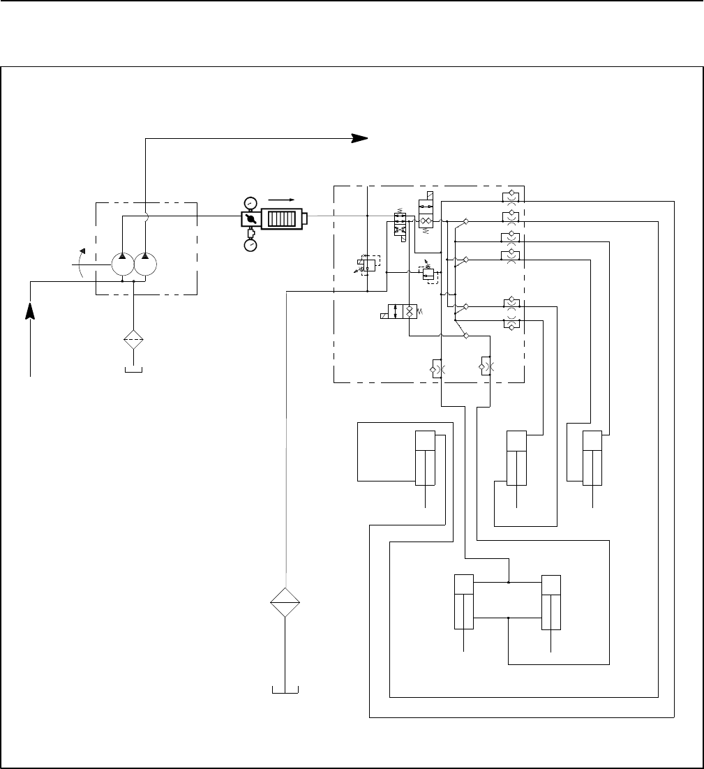
Reelmaster 5010- HHydraulic System Page 4 - 44
Gear Pump (P1) Flow Test
(Using Tester with Pressure Gauges and Flow Meter)
Figure 41
T
C4
P4
C5
C1
C2/3C2/3 L
LEFT
FRONT
RIGHT
FRONT
FRONT
CENTER
REAR
C4 L
C5 L
C1 L
REAR
LEFT RIGHT
G4
SV3
SV1
SV2
R7
SVRV
CV4
CV1
CV5
CV23
TESTER
(NOT ENERGIZED)
LIFT
CONTROL
MANIFOLD
TO STEERING CONTROL VALVE AND CHARGE CIRCUIT
100 MESH
SUCTION
STRAINER
P1 P2
INTERNAL
CASE
DRAIN
PUMP (P3)
PISTON
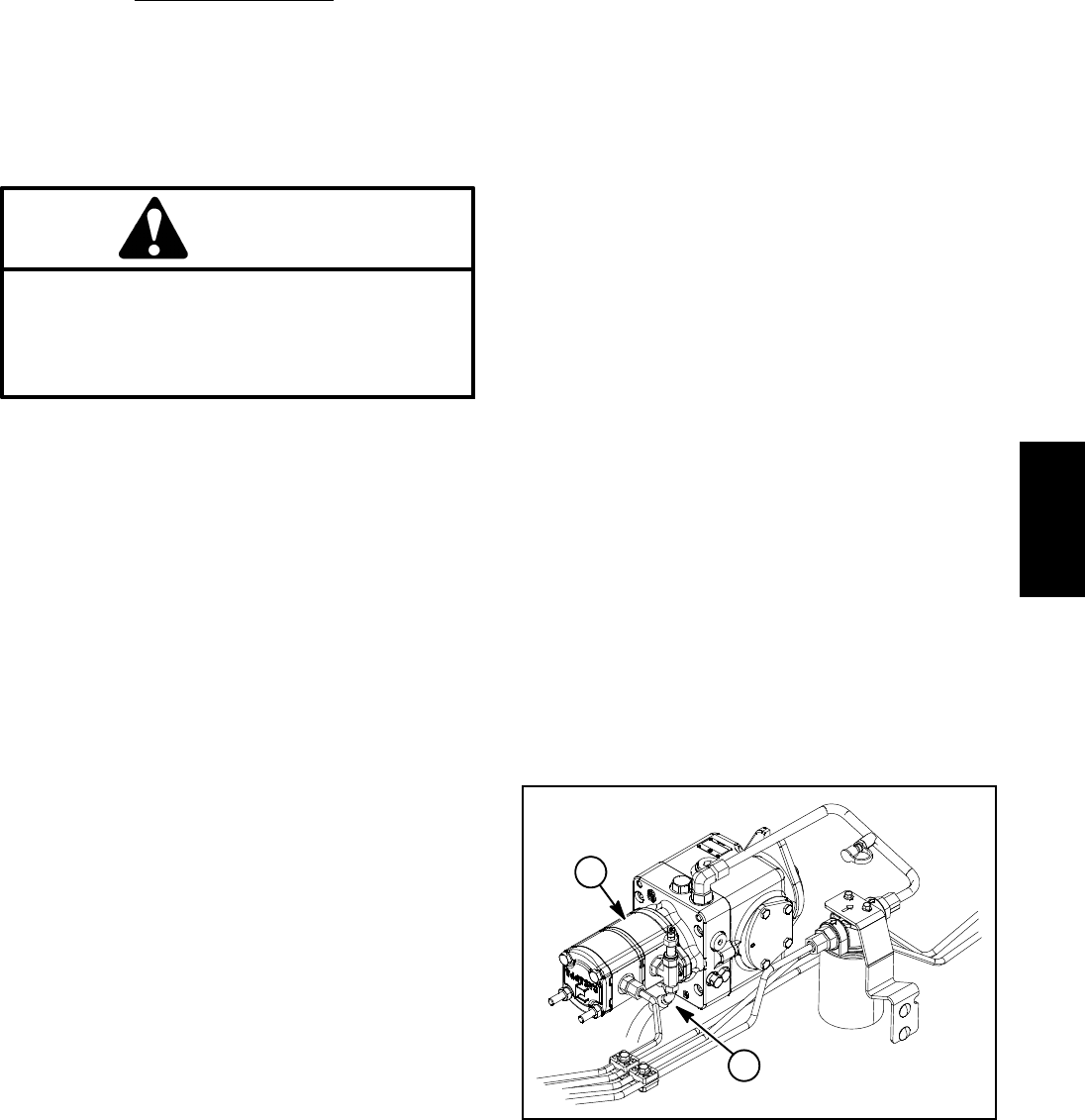
Reelmaster 5010- H Hydraulic SystemPage 4 - 45
The gear pump section (P1) flow test should be per-
formed to make sure that the cutting unit lift circuit has
adequate hydraulic flow.
Procedure for Gear Pump (P1) Flow Test
1. Parkmachineonalevelsurfacewiththecuttingunits
lowered and disengaged. Make sure engine is off. Apply
the parking brake.
2. Read Precautions For Hydraulic Testing in this sec-
tion.
CAUTION
Before opening hydraulic system, operate all hy-
draulic controls to relieve system pressure and
avoid injury from pressurized hydraulic oil. See
Relieving Hydraulic System Pressure in the Gen-
eral Information section of this chapter.
3. Raise and prop operator seat to allow access to hy-
draulic pump assembly.
4. Thoroughly clean junction of hydraulic hose and tee
fitting on left side of 1st gear pump section (Fig. 42). Dis-
connect hose from left side pump fitting.
IMPORTANT: Make sure that the oil flow indicator
arrow on the flow meter is showing that the oil will
flow from the 1st pump section (P1), through the
tester and to the hydraulic hose.
5. Install tester with pressure gauge and flow meter be-
tween gear pump fitting and disconnected hose to allow
flow from gear pump section to tester. Connect tester in-
let hose to the pump fitting. Connect the tester outlet
hose to the disconnected hydraulic hose. Make sure
the flow control valve on tester is fully open.
6. Make sure that the traction pedal is in neutral and the
parking brake is engaged.
7. Start engine and run at idle speed. Check for any hy-
draulic leakage from test connections and correct be-
fore proceeding with test.
8. Make sure hydraulic oil is at normal operating tem-
perature by operating the machine under load for
approximately ten (10) minutes.
9. Increase engine speed to high idle speed (3000
RPM). Use the InfoCenter Display to verify that engine
speed is correct.
IMPORTANT: The gear pump is a positive displace-
ment type. If pump flow is completely restricted or
stopped, damage to the pump, tester or other com-
ponents could occur.
10.While carefully watching pressure gauge on tester,
slowly close the tester flow control valve until 1000 PSI
(69 bar) is obtained on gauge. Make sure that engine
speed is still correct.
FLOW TESTER READING TO BE: A pump in good
condition should have a flow of approximately 3
GPM (11.4 LPM) at 1000 PSI (69 bar).
11. Once the gear pump flow has been determined,
open the tester flow control valve, stop engine and re-
cord test results.
12.Ifflowislessthan2.5 GPM (9.6 LPM) or a pressure
of 1000 PSI (69 bar) cannot be obtained, consider that
a gear pump problem exists. Check for restriction in
gear pump suction hose. If intake is not restricted, re-
move gear pump and repair or replace pump as neces-
sary (see Hydraulic Pump Assembly and Gear Pump
Service in the Service and Repairs section of this chap-
ter).
NOTE: If the flow from the 1st gear pump section (P1)
is low, the operation of all lift cylinders will be affected.
13.After testing is completed, make sure that engine is
stopped, then relieve hydraulic system pressure (See
Relieving Hydraulic System Pressure in the General In-
formation section of this chapter). Disconnect tester
from gear pump tee fitting and hydraulic hose. Recon-
nect machine hose to pump fitting.
14.Lower and secure operator seat.
1. 1st gear pump section 2. Hydraulic hose
Figure 42
2
1
Hydraulic
System
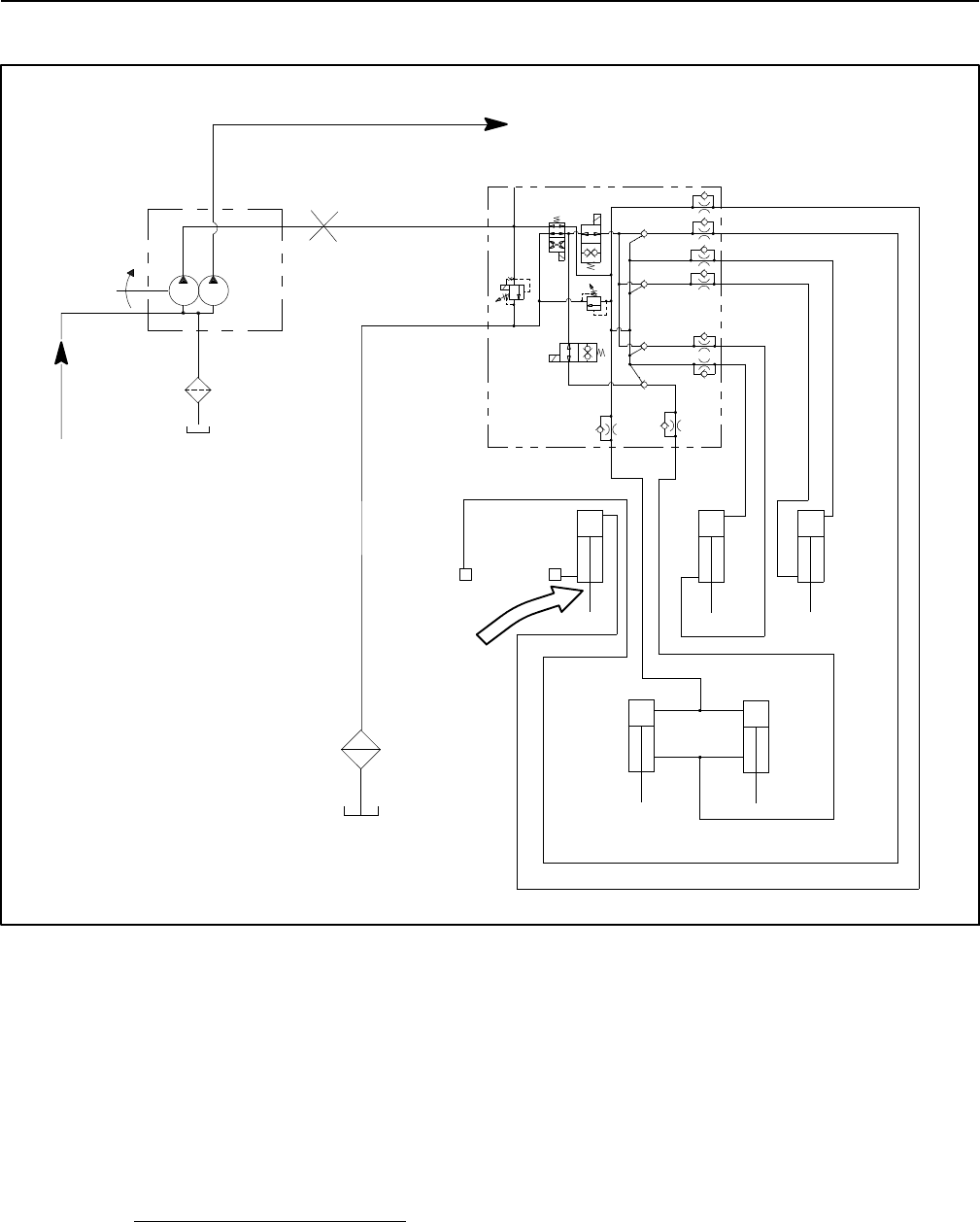
Reelmaster 5010- HHydraulic System Page 4 - 46
Lift Cylinder Internal Leakage Test
Figure 43
T
C4
P4
C5
C1
C2/3C2/3 L
LEFT
FRONT
RIGHT
FRONT
FRONT
CENTER
REAR
C4 L
C5 L
C1 L
REAR
LEFT RIGHT
G4
SV3
SV1
SV2
R7
SVRV
CV4
CV1
CV5
CV23
CHECK FOR
CYLINDER
(PARTIALLY
RAISED)
LEFT FRONT (#5) LIFT CYLINDER TEST SHOWN
PLUG
LIFT
CONTROL
MANIFOLD
CAP
EXTENDING
TO STEERING CONTROL VALVE AND CHARGE CIRCUIT
100 MESH
SUCTION
STRAINER
P1 P2
INTERNAL
CASE
DRAIN
PUMP (P3)
PISTON
The lift cylinder internal leakage test should be per-
formed if a cutting unit raise and lower problem is identi-
fied. This test will determine if a lift cylinder is faulty.
NOTE: Cutting unit raise/lower circuit operation will be
affected by lift cylinder binding, extra weight on the cut-
ting units and/or binding of lift components. Make sure
that these items are checked before proceeding with lift
cylinder internal leakage test.
Procedure for Lift Cylinder Internal Leakage Test:
1. Parkmachineonalevelsurfacewiththecuttingunits
disengaged and in the turn- around position. Turn the
engine off and apply the parking brake.
2. Read Precautions For Hydraulic Testing in this sec-
tion.
3. For the lift cylinder that is to be tested, use a jack to
raise the lift arm slightly. This will remove the load from
the lift cylinder and relieve lift cylinder hydraulic pres-
sure. Leave the jack under the lift arm to support the lift
arm and to prevent the lift arm from lowering.
NOTE: If either of the rear lift cylinders is being tested,
both rear lift arms need to be supported.
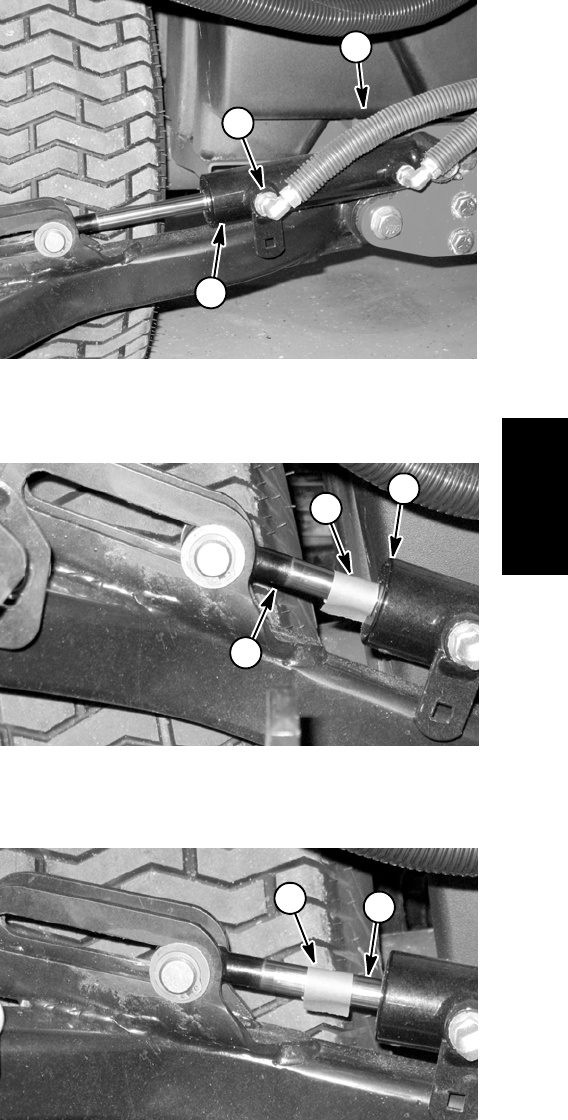
Reelmaster 5010- H Hydraulic SystemPage 4 - 47
4. Thoroughly clean the area around the end of the hy-
draulic hose at the rod end of the lift cylinder for the sup-
ported lift arm. Disconnect the hydraulic hose from the
lift cylinder rod end fitting (Fig. 44).
IMPORTANT: When capping lift cylinder fitting and
hydraulic hose end, use a steel cap and plug to en-
sure that fluid leakage will not occur. Plastic plugs
will not hold hydraulic pressure that will be devel-
oped during this test procedure.
5. Place a steel cap on the open lift cylinder fitting to
seal the lift cylinder. Also, install a steel plug in the open
end of the disconnected hose to prevent leakage or con-
tamination.
6. Slowly lower the jack and remove it from under the
lift arm. The cutting unit should settle slightly and then
be supported by the capped lift cylinder.
7. Mark the position of the lift cylinder rod at the lift cylin-
der head with a piece of tape (Fig. 45).
8. Leave the machine parked for two (2) hours and
monitor the lift cylinder. The weight of the cutting unit
may cause the lift cylinder to gradually extend. Use the
tape location to determine lift cylinder rod movement
(Fig. 46).
A. If lift cylinder rod movement is less than 1.250”
(31.7 mm) after two (2) hours, make sure that the cut-
ting unit has not settled to the ground. If the cutting
unit is still suspended after two (2) hours and lift cylin-
der rod movement is less than 1.250” (31.7 mm),
consider that the lift cylinder is in good condition. A
cylinder in good, usable condition will show minimal
movement.
B. Rod movement in excess of 1.250” (31.7 mm) af-
ter two (2) hours indicates that the lift cylinder may
have internal seal damage or excessive wear. Re-
move and inspect the lift cylinder (see Lift Cylinder
and Lift Cylinder Service in the Service and Repairs
section of this chapter).
9. Once lift cylinder condition has been determined,
use a jack to raise the lift arm slightly which will remove
the load from the lift cylinder. Allow the jack to support
the lift arm and to prevent it from lowering. Remove the
capfromthecylinderfittingandtheplugfromthehy-
draulic hose. Connect the hydraulic hose to the lift cylin-
der fitting.
10.Remove jack from under the lift arm. Start engine
and operate lift cylinders through several up and down
cycles. Stop the engine and check for any hydraulic
leakage.
11. If needed, repeat steps 3 through 9 for other lift cylin-
ders.
12.After lift cylinder testing is completed, check oil level
in hydraulic reservoir and adjust as necessary.
1. Lift cylinder (#5 shown)
2. Cylinder rod end fitting
3. Hydraulic hose
Figure 44
3
2
1
1. Lift cylinder rod
2. Lift cylinder head
3. Tape (initial position)
Figure 45
2
1
3
1. Tape (after 2 hours) 2. Cylinder rod movement
Figure 46
2
1
Hydraulic
System
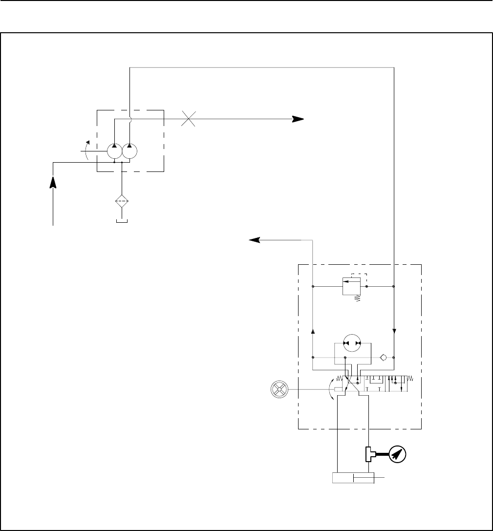
Reelmaster 5010- HHydraulic System Page 4 - 48
Steering Relief Valve (R10) Pressure Test
Figure 47
STEERING WHEEL TURNED
FOR RIGHT TURN
OUT IN
V1
RL
STEERING
R10
TP
CYLINDER
CONTROL
STEERING
VALVE
PRESSURE
GAUGE
MANIFOLD
TO LIFT CONTROL
TO TRACTION
CHARGE CIRCUIT
100 MESH
SUCTION
STRAINER
P1 P2
INTERNAL
CASE
DRAIN
PUMP (P3)
PISTON
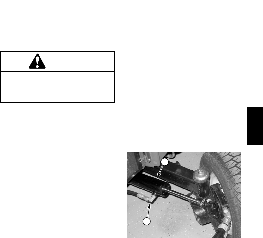
Reelmaster 5010- H Hydraulic SystemPage 4 - 49
The steering relief valve (R10) pressure test should be
performed to make sure that the steering circuit relief
pressure is correct.
Procedure for Steering Relief Valve (R10) Pressure
Test:
1. Parkmachineonalevelsurfacewiththecuttingunits
lowered and disengaged. Make sure engine is off. Apply
the parking brake.
2. Read Precautions For Hydraulic Testing in this sec-
tion.
CAUTION
Before opening hydraulic system, operate all hy-
draulic controls to relieve system pressure and
avoid injury from pressurized hydraulic oil. See
Relieving Hydraulic System Pressure in the Gen-
eral Information section of this chapter.
3. Thoroughly clean the area around the hydraulic hose
at the rod end of the steering cylinder (Fig. 48).
4. Remove hydraulic hose from the fitting on the rod
end of the steering cylinder.
5. Install a tee fitting between the disconnected hydrau-
lic hose and the steering cylinder fitting. Install a 5000
PSI (350 bar) pressure gauge to the tee fitting.
6. After installing pressure gauge, start engine and run
at idle speed. Check for any hydraulic leakage from test
connections and correct before proceeding with test.
7. Make sure hydraulic oil is at normal operating tem-
perature by operating the machine under load for
approximately ten (10) minutes.
8. Increase engine speed to high idle speed (3000
RPM).
IMPORTANT: Hold steering wheel at full lock only
long enough to get a system pressure reading.
Holding the steering wheel against the stop for an
extended period may damage the steering control
valve.
IMPORTANT: As steering wheel is turned, make
sure that pressure gauge is not contacted by any
machine parts.
9. Watch pressure gauge carefully while turning the
steering wheel for a left hand turn (counter- clockwise)
and holding.
10.System pressure should be approximately 1000 PSI
(69 bar) as the relief valve lifts. After determining relief
pressure, return steering wheel to the neutral position.
11. Shut off engine. Record test results.
12.If specification is not met, repair or replace steering
control valve (relief valve in steering control valve is not
replaceable). Gear pump section (P2) could also be
suspected of wear, damage or inefficiency (see Gear
Pump (P2) Flow Test in this section).
NOTE: If the flow from the 2nd gear pump section (P2)
is low, the traction charge circuit and steering circuit will
both be affected.
13.After steering relief valve testing is completed, make
sure that engine is stopped, then relieve hydraulic sys-
tem pressure (See Relieving Hydraulic System Pres-
sure in the General Information section of this chapter).
Remove tee fitting and pressure gauge from hydraulic
hose and steering cylinder. Reconnect hydraulic hose to
steering cylinder fitting.
1. Steering cylinder 2. Rod end fitting
Figure 48
1
2
Hydraulic
System
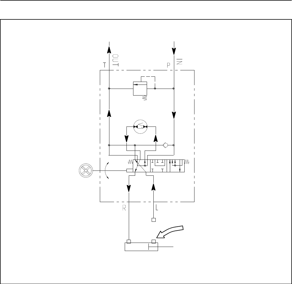
Reelmaster 5010- HHydraulic System Page 4 - 50
Steering Cylinder Internal Leakage Test
Figure 49
STEERING
CYLINDER
STEERING
CONTROL
VALVE
(FULLY EXTENDED)
LOOK FOR LEAKAGE
PLUG
STEERING WHEEL
TURNED FOR
RIGHT TURN
R10
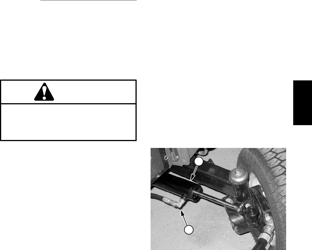
Reelmaster 5010- H Hydraulic SystemPage 4 - 51
The steering cylinder internal leakage test should be
performed if a steering problem is identified. This test
will determine if the steering cylinder is faulty.
NOTE: Steering circuit operation will be affected by
rear tire pressure, steering cylinder binding, extra
weight on the vehicle and/or binding of rear axle steering
components. Make sure that these items are checked
before proceeding with steering cylinder internal leak-
age test.
Procedure for Steering Cylinder Internal Leakage
Test:
1. Make sure hydraulic oil is at normal operating tem-
perature by operating the machine under load for
approximately ten (10) minutes.
2. Parkmachineonalevelsurfacewiththecuttingunits
lowered and disengaged. Make sure engine is off. Apply
the parking brake.
3. Read Precautions For Hydraulic Testing.
CAUTION
Before opening hydraulic system, operate all hy-
draulic controls to relieve system pressure and
avoid injury from pressurized hydraulic oil. See
Relieving Hydraulic System Pressure in the Gen-
eral Information section of this chapter.
4. Turn the steering wheel for a right turn (clockwise) so
the steering cylinder rod is fully extended.
5. Thoroughly clean the area around the hydraulic hose
at the rod end of the steering cylinder (Fig. 50).
6. Place a drain pan under the steering cylinder. Re-
move hydraulic hose from the fitting on the rod end of the
steering cylinder. Plug the end of the hose.
IMPORTANT: When capping hydraulic hose end,
use a steel cap to ensure that fluid leakage will not
occur. Plastic plugs will not hold hydraulic pressure
that may be developed during this test procedure.
7. Install a steel plug in the open end of the discon-
nected hose to prevent leakage or contamination.
8. Remove all hydraulic oil from drain pan. Make sure
that empty drain pan remains under the open fitting of
the steering cylinder.
9. With the engine off, continue turning the steering
wheel for a right turn (clockwise) with the steering cylin-
der fully extended. Observe the open fitting on the steer-
ing cylinder as the wheel is turned. If oil comes out of the
fitting while turning the steering wheel to the right, the
steering cylinder has internal leakage and must be re-
paired or replaced (see Steering Cylinder and Steering
Cylinder Service in the Service and Repairs section of
this chapter). Check drain pan for any evidence of oil
that would indicate cylinder leakage.
10.When testing is completed, remove plug from the hy-
draulic hose. Reconnect hose to the steering cylinder fit-
ting.
11. If a steering problem exists and the steering cylinder
tested acceptably, the steering control valve requires
service (see Steering Control Valve and Steering Con-
trol Valve Service in the Service and Repairs section of
this chapter). Gear pump section (P2) could also be sus-
pected of wear, damage or inefficiency (see Gear Pump
(P2) Flow Test in this section).
NOTE: If the flow from the 2nd gear pump section (P2)
is low, the traction charge circuit and steering circuit will
both be affected.
12.Check oil level in hydraulic reservoir and adjust if
needed.
1. Steering cylinder 2. Rod end fitting
Figure 50
1
2
Hydraulic
System

Reelmaster 5010- HHydraulic System Page 4 - 52
Service and Repairs
General Precautions for Removing and Installing Hydraulic System Components
Before Repair or Replacement of Components
1. Before removing any parts from the hydraulic sys-
tem, park machine on a level surface, lower cutting
units, engage parking brake and stop engine. Remove
key from the ignition switch.
2. Thoroughly clean machine before disconnecting, re-
moving or disassembling any hydraulic components.
Make sure hydraulic components, hose connections
and fittings are thoroughly cleaned. Always keep in mind
the need for cleanliness when working on hydraulic
components.
CAUTION
Before loosening any hydraulic component, op-
erate all hydraulic controls to relieve system
pressure and avoid injury from pressurized hy-
draulic oil. See Relieving Hydraulic System Pres-
sure in the General Information section of this
chapter.
3. Operate all hydraulic controls to relieve system pres-
sure before loosening any hydraulic connection (see
Relieving Hydraulic System Pressure in the General In-
formation section of this chapter).
4. Put caps or plugs on any hydraulic lines, hydraulic fit-
tings or components left open or exposed to prevent
contamination.
5. Before disconnecting hydraulic lines or hoses, place
labels to ensure proper installation after repairs are
completed.
6. Note the position of hydraulic fittings (especially el-
bow fittings) on hydraulic components before removing
the fittings. Mark parts if necessary to make sure that fit-
tings will be aligned properly when reinstalling hydraulic
hoses and tubes.
After Repair or Replacement of Components
1. If component failure is severe or hydraulic system is
contaminated, flush hydraulic system (see Flush Hy-
draulic System in this section).
2. Lubricate O- rings and seals with clean hydraulic oil
before installing hydraulic components.
3. Make sure all caps or plugs are removed from hy-
draulic tubes, hydraulic fittings and components before
reconnecting.
4. Use proper tightening methods when installing hy-
draulic hoses and fittings (see Hydraulic Hose and Tube
Installation and Hydraulic Fitting Installation in the Gen-
eral Information section of this chapter).
5. After repairs, check control linkages and cables for
proper adjustment, binding or broken parts.
6. After disconnecting or replacing any hydraulic com-
ponents, operate machine functions slowly until air is
out of system (see Hydraulic System Start Up in this sec-
tion).
7. Check for hydraulic oil leaks. If any leaks are discov-
ered, shut off engine and correct leaks before continuing
machine operation.
8. After performing any hydraulic repairs, check oil lev-
el in hydraulic reservoir and add correct oil if necessary.

Reelmaster 5010- H Hydraulic SystemPage 4 - 53
Check Hydraulic Lines and Hoses
Keep body and hands away from pin hole leaks
or nozzles that eject hydraulic fluid under high
pressure. Use paper or cardboard, not hands, to
search for leaks. Hydraulic fluid escaping under
pressure can have sufficient force to penetrate
the skin and cause serious injury. If fluid is in-
jected into the skin, it must be surgically re-
moved within a few hours by a doctor familiar
with this type of injury. Gangrene may result from
such an injury.
CAUTION
Check hydraulic lines and hoses daily for leaks, kinked
lines, loose mounting supports, wear, loose fittings,
weather deterioration and chemical deterioration. Make
all necessary repairs before operating the machine.
Hydraulic
System

Reelmaster 5010- HHydraulic System Page 4 - 54
Flush Hydraulic System
IMPORTANT: Flush the hydraulic system any time
there is a severe component failure or the system is
contaminated. Contaminated oil appears milky or
black or contains metal particles.
1. Park machine on a level surface. Lower cutting units,
stop engine, engage parking brake and remove key
from ignition switch.
2. Drain hydraulic reservoir.
3. Clean area around the mounting area of the hydrau-
lic filter. Remove and discard hydraulic filter.
4. Drain entire hydraulic system. Drain all hoses, tubes
and components while the system is warm. Flush hoses
and tubes to remove any contamination.
IMPORTANT: Follow all local codes and regulations
when recycling or disposing hydraulic fluid and oil
filter.
IMPORTANT: If a failure occurred in the traction cir-
cuit, traction circuit component disassembly and
thorough cleaning may be required to remove con-
taminates from the traction circuit. Because the
traction circuit is a closed loop, any contamination
will remain in the circuit and can cause additional
component damage unless it is removed.
5. Make sure the mounting surface of the hydraulic filter
is clean. Apply clean hydraulic oil to gasket on new filter.
Screw filter onto filter head until gasket contacts mount-
ing plate, then tighten filter an additional 1/2 turn.
IMPORTANT: Use only hydraulic fluids specified in
Traction Unit Operator’s Manual. Other fluids could
cause system damage.
6. Fill hydraulic reservoir with new hydraulic oil to prop-
er level.
7. Disconnect wire harness connector from the fuel ac-
tuator to prevent the engine from starting.
8. Make sure traction pedal is in neutral and the PTO
switch is OFF. Turn ignition key switch to start; engage
starter for ten (10) seconds to prime hydraulic pumps.
Wait sixty (60) seconds to allow the starter motor and
starter solenoid to cool. Repeat this step again.
9. Connect wire harness connector to the fuel actuator
to allow engine to start.
10.Start engine and let it idle at low speed for a minimum
of two (2) minutes.
11. Increase engine speed to high idle for minimum of
one (1) minute under no load.
12.Rotate steering wheel in both directions several
times. Raise and lower cutting units several times.
13.Shut off engine and check for hydraulic oil leaks.
Check oil level in hydraulic reservoir and add correct oil
if necessary.
14.Operate the machine for two (2) hours under normal
operating conditions.
15.Check condition of hydraulic oil. If the fluid shows any
signs of contamination, repeat steps 1 through 14 again.
16.Resume normal operation and follow recommended
maintenance intervals.
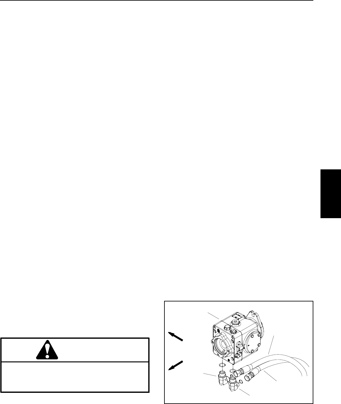
Reelmaster 5010- H Hydraulic SystemPage 4 - 55
Filtering Closed- Loop Traction Circuit
Filtering of a closed- loop hydraulic system after a major
component failure (e.g. traction (piston) pump or wheel
motor) is a requirement to prevent debris from transmit-
ting throughout the system. If a closed- loop hydraulic
system filtering tool is not used to ensure system cleanli-
ness, repeat failures, as well as subsequent damage to
other hydraulic components in the affected system, will
occur. To effectively remove contamination from
closed-looptractioncircuit,useoftheTorohighflowhy-
draulic filter and hydraulic hose kits are recommended
(see Special Tools in this chapter).
1. Parkmachineonalevelsurfacewithenginestopped
and key removed from ignition switch.
2. Raise and support machine so all wheels are off the
ground (see Jacking Instructions in Chapter 1 - Safety).
NOTE: If wheel motor was replaced, install high flow fil-
ter to the inlet of the new motor instead of to the piston
pump fitting. This will prevent system contamination
from entering and damaging the new wheel motor.
3. Thoroughly clean junction of hydraulic hose and left
side elbow fitting on bottom of piston (traction) pump
(Fig. 51). Disconnect hose from left side pump fitting.
4. Connect Toro high flow hydraulic filter in series be-
tween piston (traction) pump fitting and disconnected
hose. Use hydraulic hose kit (see Special Tools in this
chapter) to connect filter to machine. Make sure that fit-
ting and hose connections are properly tightened.
IMPORTANT: Use only hydraulic fluids specified in
Operator’s Manual. Other fluids could cause system
damage.
5. After installing high flow filter to machine, check and
fill hydraulic reservoir with new hydraulic oil as required.
6. Start engine and run at idle speed. Check for any hy-
draulic leakage from filter and hose connections. Cor-
rect any leaks before proceeding.
CAUTION
All wheels will be off the ground and rotating dur-
ing this procedure. Make sure machine is well
supported so it will not move and accidentally
fall to prevent injuring anyone around machine.
IMPORTANT: While engaging the traction circuit,
monitor the indicator on the high flow hydraulic fil-
ter. If the indicator should show red, either reduce
pressure on the traction pedal or reduce engine
speed to decrease hydraulic flow through the filter.
7. With engine running at low idle speed, slowly move
the traction pedal to the forward direction to allow flow
through the traction circuit and high flow filter. Keep trac-
tion circuit engaged for five (5) minutes while gradually
increasing both forward pressure on traction pedal and
engine speed. Monitor filter indicator to make sure that
green color is showing during operation.
8. With engine running at high idle speed and traction
pedal moved to the forward direction, periodically apply
brakes to increase pressure in traction circuit. While
monitoring filter indicator, continue this process for an
additional five (5) minutes.
IMPORTANT: If using a filter that is not the Toro high
flow filter that is bi- directional, do not press the
traction pedal in the reverse direction. If flow is re-
versed when using a filter that is not bi- directional,
debris from the filter will re- enter the traction cir-
cuit.
9. With engine running at high idle speed, alternately
move traction pedal from forward to reverse. While mon-
itoring filter indicator, continue this process for an addi-
tional five (5) minutes.
10.Shut engine off and remove key from ignition switch.
11. Remove high flow hydraulic filter and hydraulic hose
kit from machine. Connect hydraulic hose to left side pis-
ton (traction) pump fitting. Make sure to properly tighten
hose (see Hydraulic Hose and Tube Installation in the
General Information section of this chapter).
12.Lower machine to ground.
13.Check oil level in hydraulic reservoir and add correct
oil if necessary.
1. Piston (traction) pump
2. RH elbow fitting
3. Hyd hose (forward)
4. LH elbow fitting
5. Hyd hose (reverse)
Figure 51
FRONT
RIGHT
2
3
1
4
5
Hydraulic
System

Reelmaster 5010- HHydraulic System Page 4 - 56
Hydraulic System Start- up
NOTE: When initially starting the hydraulic system with
new or rebuilt components such as pumps, wheel mo-
tors or lift cylinders, it is important that this start- up pro-
cedure be used. This procedure reduces the chance of
damaging the system or its components from not purg-
ing the system of air.
1. After the hydraulic system components have been
properly installed and if the piston (traction) pump was
rebuilt or replaced, make sure piston (traction) pump
housing is at least half full of clean hydraulic oil.
2. Make sure all hydraulic connections and lines are se-
cured tightly.
3. Drain, flush and refill hydraulic system and change
hydraulic oil filter if component failure was severe or sys-
tem is contaminated (see Flush Hydraulic System in this
section).
4. Make sure hydraulic reservoir is full. Add correct oil
if necessary.
5. Check control linkage for proper adjustment, binding
or broken parts.
6. Disconnect electrical connector to the engine fuel
actuator to prevent the engine from starting.
7. Make sure traction pedal is in neutral and the PTO
switch is OFF. Turn ignition key switch to start; engage
starter for ten (10) seconds to prime hydraulic pumps.
Wait sixty (60) seconds to allow the starter motor and
starter solenoid to cool. Repeat this step again.
8. Connect fuel actuator to allow engine to start.
9. Make sure traction pedal is in neutral and the PTO
switch is OFF. Start engine and run it at low idle. The
charge pump should pick up oil and fill the hydraulic sys-
tem. If there is no indication of fill in thirty (30) seconds,
stop the engine and determine the cause.
10.If the piston (traction) pump was replaced or rebuilt,
run the traction unit so the wheels turn slowly for ten (10)
minutes.
11. Operate the traction unit (including steering and cut-
ting unit lift/lower) by gradually increasing the work load
to full over a ten (10) minute period.
12.Stop the machine. Check oil level in hydraulic reser-
voir and add correct oil if necessary. Check hydraulic
components for leaks and tighten any loose connec-
tions.

Reelmaster 5010- H Hydraulic SystemPage 4 - 57
This page is intentionally blank.
Hydraulic
System
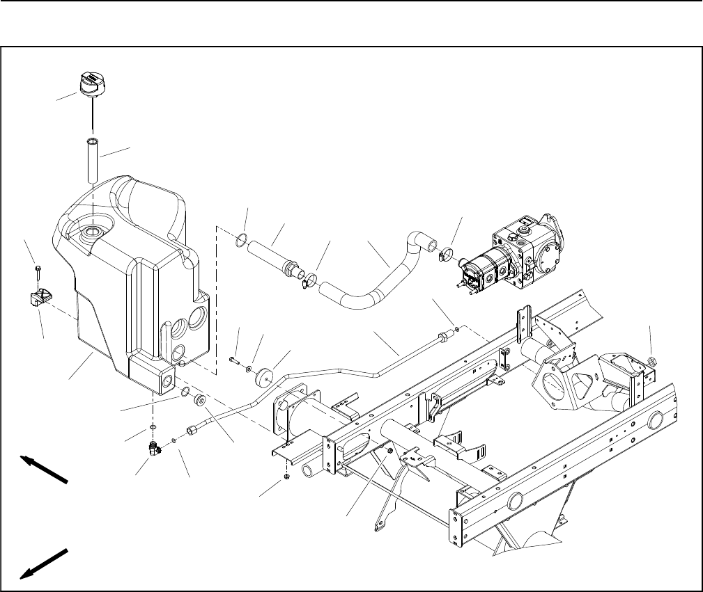
Reelmaster 5010- HHydraulic System Page 4 - 58
Hydraulic Reservoir
1. Suction strainer
2. Hydraulic reservoir
3. Recess bumper
4. Clamp (2 used)
5. Suction hose
6. Hose clamp (2 used)
7. Reservoir cap
8. Washer head screw (2 used)
9. Flange nut (3 used)
10. Cap screw
11. Flat washer
12. Filter screen
13. Hydraulic tube
14. O- ring
15. 90o hydraulic fitting
16. O- ring
17. SAE #16 plug
18. O- ring
19. Bulkhead nut
20. O- ring
Figure 52
FRONT
RIGHT
2
3
6
8
9
10 11 13
1
5
7
12
14
15 16
17
18
19
20
4
6
9
16

Reelmaster 5010- H Hydraulic SystemPage 4 - 59
Removal (Fig. 52)
1. Thoroughly clean hydraulic hose ends and fittings on
hydraulic reservoir to prevent hydraulic system contami-
nation.
2. Drain hydraulic oil from reservoir.
3. Disconnect hydraulic lines from fittings on the reser-
voir. Allow hydraulic lines to drain into a suitable contain-
er. Plug or cap openings of reservoir and hydraulic lines
to prevent leakage or contamination.
4. Remove hydraulic reservoir using Figure 52 as a
guide.
5. Remove suction strainer (item 1) from reservoir. Dis-
card O- ring.
6. If hydraulic fitting (item 15) is to be removed from re-
servoir, mark fitting orientation to allow correct assem-
bly. Remove fitting from reservoir and discard O- ring.
Inspection (Fig. 52)
1. Clean hydraulic reservoir and suction strainer with
solvent.
2. Inspect hydraulic reservoir for leaks, cracks or other
damage.
Installation (Fig. 52)
1. If fitting (item 15) was removed from reservoir, lubri-
cate and place new O- ring onto fitting. Install fitting into
reservoir opening using marks made during the removal
process to properly orientate fitting. Tighten fitting (see
Hydraulic Fitting Installation in the General Information
section of this chapter).
2. Lubricate new suction strainer O- ring and install
onto strainer. Thread suction strainer into hydraulic res-
ervoir until finger tight. Then, using a wrench, turn strain-
er into reservoir port 1- 1/2 to 2 full turns beyond finger
tight.
3. Position hydraulic reservoir to machine. Make sure
that recess bumper (item 3) on right side of frame is in-
serted into recess in reservoir.
4. Secure reservoir to frame with two (2) clamps (item
4), washer head screws (item 8) and flange nuts (item
9).
5. Remove plugs and caps placed in hoses and fittings
during the removal process.
6. Install and secure hydraulic lines to fittings on hy-
draulic reservoir (see Hydraulic Hose and Tube Installa-
tion in the General Information section of this chapter).
7. Fill hydraulic reservoir with new hydraulic fluid.
8. Operate machine. Check hydraulic lines and fittings
for leaks. Tighten any loose connections. Check hydrau-
lic oil level in reservoir and adjust if necessary.
Hydraulic
System
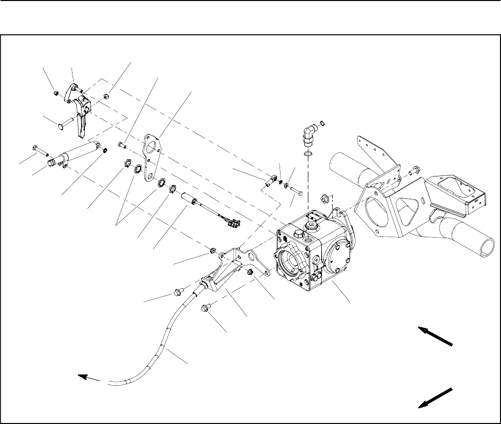
Reelmaster 5010- HHydraulic System Page 4 - 60
Piston (Traction) Pump Control Assembly
1. Flange head screw (2 used)
2. Piston (traction) pump
3. Lever damper
4. Flange nut
5. Pump plate
6. Cap screw (3 used)
7. Carriage screw
8. Lock nut
9. Pump lever
10. Flat washer
11. Flange nut
12. Lock nut
13. Cap screw
14. Cap screw
15. Traction cable bracket
16. Cable rod end
17. Traction neutral switch
18. Traction control cable
19. Flat washer
20. Flat washer
21. Jam nut (2 used)
22. Lock washer (2 used)
Figure 53
2
3
6
8
9
10
11
13
1
5
7
12
14
15
16
17
18
19 20
4
21
22
1
21
FRONT
RIGHT
TO TRACTION
PEDAL
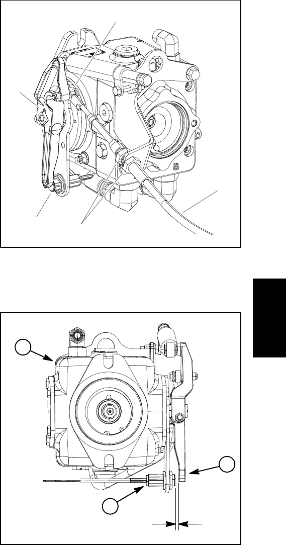
Reelmaster 5010- H Hydraulic SystemPage 4 - 61
Disassembly (Fig. 53)
1. Park the machine on a level surface, engage parking
brake, lower cutting units and stop engine. Remove key
from the ignition switch.
2. Remove components from piston (traction) pump
control assembly as needed using Figures 53 and 54 as
guides.
Assembly (Fig. 53)
IMPORTANT: To prevent traction neutral switch
(item 17) damage, make sure that no pump control
components contact switch through entire piston
(traction) pump control arm movement.
1. Install removed components to piston (traction)
pump control assembly using Figures 53 and 54 as
guides along with the following:
A. If traction neutral switch (item 17) was removed
from pump plate, adjust location of switch so that
there is from 0.094” to 0.100” (2.4 to 2.5 mm) clear-
ance between the head of neutral switch and the pis-
ton (traction) pump lever (Refer to Traction Neutral
Switch in the Adjustments section of Chapter 5 -
Electrical System for additional neutral switch infor-
mation).
2. After piston (traction) pump control assembly has
been installed, make sure that the piston pump is ad-
justed for the neutral position so that the machine does
not move or creep when the traction pedal is in neutral
(see Traction Unit Operator’s Manual).
1. Pump lever
2. Traction neutral switch
3. Traction control cable
4. Cable jam nut
5. Cable rod end
Figure 54
1
5
3
24
Figure 55
1. Piston pump
2. Pump lever
3. Traction neutral switch
2
1
3
0.094” to 0.100”
(2.4 to 2.5 mm)
Hydraulic
System
Reelmaster 5010- HHydraulic System Page 4 - 62
Hydraulic Pump Assembly
1. Gear pump assembly
2. O- ring
3. O- ring
4. Flat washer (4 used)
5. O- ring
6. Hydraulic fitting
7. Piston (traction) pump assembly
8. Socket head screw (2 used)
9. Lock washer (2 used)
10. Lock nut (2 used)
11. Flange nut (2 used)
12. Carriage screw (2 used)
13. Hydraulic tube
14. Hydraulic fitting
15. O- ring
16. Pump support bracket
17. Hydraulic tee fitting
18. Hydraulic test fitting
19. Dust cap
20. Hydraulic hose
21. Hose clamp
22. Hydraulic (suction) hose
23. O- ring
24. 90ohydraulic fitting (2 used)
25. O- ring
26. Hydraulic hose (2 used)
27. Flange head screw (2 used)
28. Flange nut (2 used)
29. Hydraulic tube
30. O- ring
31. 90ohydraulic fitting
32. O- ring
33. Engine bellhousing
34. 48 VDC motor/generator
35. Pump drive shaft
36. Cap screw (2 used)
37. Flange nut (2 used)
38. Hood saddle
Figure 56
FRONT
RIGHT
Antiseize
Lubricant
2
3
6
8
9
10
11
1
5
12
14
15
16
17
18
19
4
4
2
13
7
20
21
22
23
24
25
26
27
28
29
30
26
31
32
3
33
34
36
37
35
38
NOTE: Piston (traction) pump and gear pump should
be removed from machine as an assembly. Once re-
moved from machine, pumps can be separated for nec-
essary service.
Reelmaster 5010- H Hydraulic SystemPage 4 - 63
Removal (Fig. 56)
1. Park the machine on a level surface, engage parking
brake, lower cutting units and stop engine. Remove key
from the ignition switch.
2. Raise and support hood and operator seat. Lift hood
saddle from frame brackets and remove from machine.
3. Read the General Precautions for Removing and
Installing Hydraulic System Components at the begin-
ning of the Service and Repairs section of this chapter.
CAUTION
Before opening hydraulic system, operate all hy-
draulic controls to relieve system pressure and
avoid injury from pressurized hydraulic oil. See
Relieving Hydraulic System Pressure in the Gen-
eral Information section of this chapter.
4. To prevent contamination of the hydraulic system,
thoroughly clean piston (traction) and gear pump as-
sembly and all hydraulic connections.
5. Label hydraulic hoses to assist in assembly. Discon-
nect all hydraulic hoses and tubes from fittings on the
piston (traction) and gear pump assembly. Allow hy-
draulic lines to drain into a suitable container. Plug or
cap openings of pumps and lines to prevent contamina-
tion.
6. Remove two (2) cap screws (item 36) and flange nuts
(item 37) that secure pump drive shaft to piston (trac-
tion) pump input shaft.
7. Disconnect traction control cable from piston (trac-
tion) pump (see Piston (Traction) Pump Control Assem-
bly in this section). Carefully position traction control
cable away from piston pump.
8. Disconnect wire harness electrical connector from
traction neutral switch on piston pump control assembly
and position harness away from pump assembly.
IMPORTANT: Dry weight of pump assembly is ap-
proximately 68 pounds (31 kg).
9. Connect a lift or hoist to hole in traction cable bracket
on piston pump to support pump assembly and for pump
removal.
10.Loosen and remove two (2) carriage screws (item
12) and flange nuts (item 11) that secure pump support
bracket to frame.
11.Remove two (2) flange screws (item 27) and flange
nuts (item 28) that secure piston (traction) pump flange
to machine frame.
1. Piston (traction) pump
2. Gear pump
3. Traction cable bracket
Figure 57
21
3
1. Piston pump case drain 2. Gear pump suction port
Figure 58
after gear pump is removed.
drain and gear pump suction port
install plugs in piston pump case
To prevent draining the pumps,
Remove plugs before installing
gear pump to piston pump.
2
1
IMPORTANT: Make sure to not damage machine
components while removing the pump assembly.
12.Carefully lift pump assembly from the machine.
Place assembly on suitable workbench.
NOTE: A case drain exists in the piston (traction) pump
and a suction port is near the input shaft of the gear
pump (Fig. 58). When the gear pump is removed from
the piston pump, plug piston pump case drain hole to
prevent draining the piston pump.
Hydraulic
System
Reelmaster 5010- HHydraulic System Page 4 - 64
13.Remove two (2) socket head screws, lock washers
and flat washers that secure gear pump to piston (trac-
tion) pump. Remove gear pump from piston (traction)
pump. Locate and discard O- ring (item 15) from be-
tween pumps.
14.If necessary, remove hydraulic fittings from pumps.
Note orientation of fittings for assembly purposes.
15.Remove and discard all O- rings from removed hy-
draulic lines and fittings.
16.If necessary, remove two (2) lock nuts (item 10) that
secure pump support bracket (item 16) to gear pump.
Remove bracket and two (2) flat washers (item 4) from
gear pump.
Installation (Fig. 56)
1. If fittings were removed from pump assembly, lightly
lubricate new fitting O- rings with clean hydraulic oil.
Install fittings with O- rings to the pump assembly (see
Hydraulic Fitting Installation in the General Information
section of this chapter). Orientate fittings as noted dur-
ing removal.
2. If pump support bracket (item 16) was removed from
gear pump, fit flat washers and bracket to gear pump
and secure with two (2) lock nuts.
IMPORTANT: A case drain exists in the piston (trac-
tion) pump and a suction port is near the input shaft
of the gear pump (Fig. 58). Before the gear pump is
installed to the piston pump, make sure that plugs
placed in either of these ports are removed. Failure
to remove plugs will cause excessive pressure in
the piston pump and damage seals. Also, before se-
curing gear pump to piston pump, fill piston pump
housing with clean hydraulic oil through case drain
hole.
3. Remove plugs that were placed in piston pump case
drain and gear pump suction port. Fill piston pump hous-
ing with new hydraulic oil through case drain hole.
4. Lubricate and position new O- ring (item 15) be-
tween pumps. Position gear pump to piston (traction)
pump and secure with two (2) socket head screws, lock
washers and flat washers.
IMPORTANT: Make sure to not damage machine
components while installing the pump assembly.
5. Carefully lower pump assembly to machine frame.
Align piston pump input shaft to pump drive shaft and
slide pump assembly to machine frame.
6. Secure pump assembly to machine frame with two
(2) flange screws and flange nuts.
7. Secure pump support bracket to inside of frame
bracket with two (2) carriage screws (item 12) and
flange nuts (item 11).
8. Install hydraulic hoses to fittings on pump assembly
in positions noted during removal (see Hydraulic Hose
and Tube Installation in the General Information section
of this chapter).
9. Connect machine wire harness electrical connector
to traction neutral switch on piston pump control assem-
bly.
10.Position traction control cable to piston (traction)
pump. Secure cable to pump lever and cable bracket
(see Piston (Traction) Pump Control Assembly in this
section).
11. Secure pump drive shaft to piston (traction) pump in-
put shaft with two (2) cap screws (item 36) and flange
nuts (item 37).
12.Install hood saddle onto frame brackets. Lower and
secure hood and operator seat.
13.Check oil level in hydraulic reservoir and add correct
oil if necessary.
14.Follow hydraulic system start- up procedures (see
Hydraulic System Start- up in this section).
15.Check traction drive for neutral and traction neutral
switch operation. Adjust if necessary.

Reelmaster 5010- H Hydraulic SystemPage 4 - 65
This page is intentionally blank.
Hydraulic
System
Reelmaster 5010- HHydraulic System Page 4 - 66
Piston (Traction) Pump Service
1. Piston (traction) pump housing
2. Auxiliary shaft
3. Retaining ring
4. Ball bearing
5. Retaining ring
6. Seal
7. Backup washer
8. Bearing (2 used)
9. O- ring
10. Trunnion cover
11. Screw (4 used)
12. Plug (2 used)
13. O- ring
14. Seal
15. Trunnion cover
16. Screw (4 used)
17. Spring
18. Charge relief poppet
19. Seal kit
20. Relief valve (forward)
21. Screw (4 used)
22. Coupling
23. End cap
24. Seal kit
25. Seal nut
26. Pin
27. Swashplate
28. Thrust plate
29. Shim kit
30. O- ring
31. Charge relief plug
32. Retaining ring
33. Bearing
34. Neutral return arm
35. Neutral return pivot
36. Spring
37. Cylinder block kit
38. Valve plate
39. Slotted pin
40. End cap gasket
41. Seal kit
42. Relief valve (reverse)
43. Needle bearing
44. Loop flushing spool
45. Spring
46. Plug
47. O- ring
48. Bypass valve
Figure 59
9
6
7
3
4
1
5
2
8
10
12
11
14
13
15
16
25
26
27
28
26
5
8
9
32 33
34
35
37
38
36
39
40
41
42
43
44 45
47
48
46
24
23
22
18 17
21
20
29 30
19
31
12
13
NOTE: For piston (traction) pump repair information,
see the Sauer- Danfoss LPV Closed Circuit Axial Piston
Pumps Repair Manual and Service Instructions at the
end of this chapter.
IMPORTANT: If a piston (traction) pump failure oc-
curred, refer to Traction Circuit Component Failure
in the General Information section for information
regarding the importance of removing contamina-
tion from the traction circuit.

Reelmaster 5010- H Hydraulic SystemPage 4 - 67
This page is intentionally blank.
Hydraulic
System
Reelmaster 5010- HHydraulic System Page 4 - 68
Gear Pump Service
1. Front cover
2. Dowel pin (4 used)
3. Square section seal (4 used)
4. Back- up seal (4 used)
5. Pressure seal (4 used)
6. Thrust plate (4 used)
7. Drive shaft
8. Driven gear
9. Body
10. Flange
11. Splined connecting shaft
12. Drive gear
13. Driven gear
14. Body
15. Dowel pin (2 used)
16. Rear cover
17. Washer (4 used)
18. Stud bolt (2 used)
19. Nut (2 used)
20. Cap screw (2 used)
Figure 60
33 ft- lb
(45 N- m)
4
1
2
9
10 11
8
5
67
12
3
13
14
17
18
15
16
19
20
Disassembly (Fig. 60)
NOTE: The gear pump must be replaced as a complete
assembly. Individual gears, housings and thrust plates
are not available separately. Disassemble gear pump
for cleaning, inspection and seal replacement only.
IMPORTANT: Keep bodies, gears and thrust plates
for each pump section together; do not mix parts
between pump sections.
1. Plug pump ports and thoroughly clean exterior of
pump with cleaning solvent. Make sure work area is
clean.
2. Use a marker to make a diagonal line across the
gear pump for assembly purposes (Fig. 61).
IMPORTANT: Use caution when clamping gear
pump in a vise to avoid distorting any pump compo-
nents.
3. Secure the front cover of the pump in a vise with the
drive shaft pointing down.
4. Loosen the two (2) cap screws and two (2) nuts that
secure pump assembly.
5. Remove pump from vise and remove loosened fas-
teners.
6. Support the pump assembly and gently tap the pump
case with a soft face hammer to loosen the pump sec-
tions. Be careful to not drop parts or disengage gear
mesh.
Reelmaster 5010- H Hydraulic SystemPage 4 - 69
IMPORTANT: Mark the relative positions of the gear
teeth and the thrust plates so they can be reassem-
bled in the same position. Do not touch the gear sur-
faces as residue on hands may be corrosive to gear
finish.
7. Remove the thrust plates and seals from each pump
section. Before removing each gear set, apply marking
dye to mating teeth to retain ”timing”. Pump efficiency
may be affected if the teeth are not installed in the same
position during assembly. Keep the parts for each pump
section together; do not mix parts between sections.
8. Clean all gear pump parts. Check all components for
burrs, scoring, nicks and other damage.
9. Replace the entire pump assembly if component
parts are excessively worn or scored.
Assembly (Fig. 60)
1. Apply clean hydraulic oil to all parts before assem-
bling.
NOTE: Pressure and back- up seals fit in grooves ma-
chined into thrust plates. Square section seals fit in
grooves machined in body faces.
2. Assemble pump sections starting at front cover end.
Apply grease or petroleum jelly to new section seals to
hold them in position during gear pump assembly.
3. After pump has been assembled, tighten cap screws
and nuts by hand.
4. Place a small amount of clean hydraulic fluid into the
inlet of the gear pump and rotate the drive shaft away
from the inlet one revolution. Protect the shaft if using pli-
ers for turning the shaft. If any binding is noted, disas-
semble the pump and check for assembly problems.
5. Tighten the cap screws and nuts evenly in a crossing
patterntoatorqueof33 ft- lb (45 N- m).
Figure 61
DIAGONAL LINE
Hydraulic
System
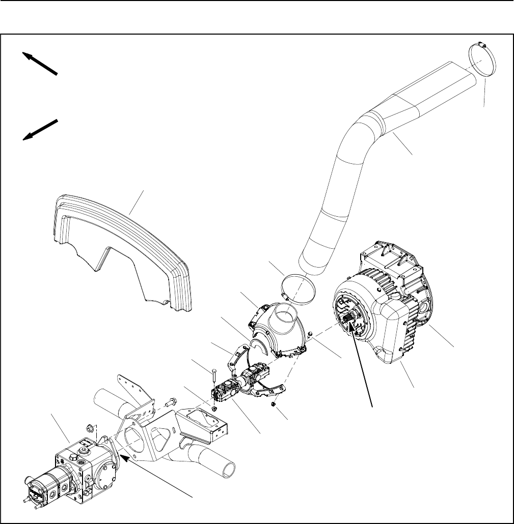
Reelmaster 5010- HHydraulic System Page 4 - 70
Hydraulic Pump Drive Shaft
1. Hood saddle
2. Air intake hose
3. Hose clamp (2 used)
4. Flange head screw (4 used)
5. Flange nut (4 used)
6. Upper intake shroud
7. Lower intake shroud
8. Brush seal (2 used)
9. 48 VDC motor/generator assembly
10. Engine bellhousing
11. Hydraulic pump assembly
12. Drive shaft assembly
13. Cap screw (4 used)
14. Flange nut (4 used)
Figure 62
FRONT
RIGHT
Antiseize
Lubricant
1
2
3
6
8
9
10
11
13
5
7
12
14
4
3
Antiseize
Lubricant
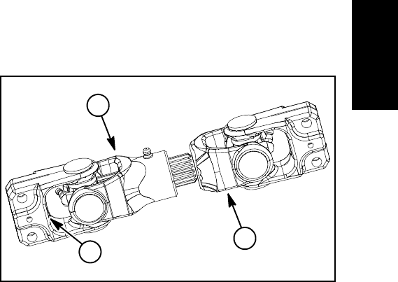
Reelmaster 5010- H Hydraulic SystemPage 4 - 71
Removal (Fig. 62)
1. Park the machine on a level surface, engage parking
brake, lower cutting units and stop engine. Remove key
from the ignition switch.
2. Raise and support hood and operator seat. Lift hood
saddle (item 1) from frame brackets and remove from
machine.
3. Loosen hose clamp that secures air intake hose
(item 2) to upper intake shroud. Carefully slide intake
hose from upper shroud.
4. Remove intake shrouds (items 6 and 7) and brush
seals (item 8) from machine.
A. Remove four (4) flange head screws (item 4) and
flange nuts (item 5) that secure upper and lower in-
take shrouds.
B. Separate tabs on upper shroud from slots on low-
er shroud. Remove shrouds and brush seals from
machine.
C. Note location of four (4) compression limiter
spacers in the upper shroud mounting holes.
5. Remove cap screws (item 13) and flange nuts (item
14) that secure drive shaft yokes to hydraulic pump input
shaft and motor/generator output shaft.
6. Slide drive shaft yokes from hydraulic pump and mo-
tor/generator shafts and remove drive shaft assembly
from machine.
Installation (Fig. 62)
1. Apply antiseize lubricant to hydraulic pump input
shaft and motor/generator output shaft.
2. Position drive shaft assembly to hydraulic pump and
motor/generator shafts. The drive shaft male yoke
should be installed onto motor/generator shaft (Fig. 63).
Position female yoke fully onto pump shaft so the shaft
end is flush with the inside of the yoke flange.
3. Secure drive shaft yokes to pump and motor/genera-
tor shafts with two (2) cap screws (item 5) and flange
nuts (item 9).
4. Lubricate drive shaft grease fittings.
5. Secure intake shrouds (items 6 and 7) and brush
seals (item 8) to machine.
A. Make sure that four (4) compression limiter spac-
ers are placed in the mounting holes in the upper in-
take shroud.
B. Position intake shrouds and brush seals around
drive shaft. Make sure that brush seals fit in grooves
of shrouds and grooves in shrouds fit onto flange on
motor/generator cover. Insert upper shroud tabs into
lower shroud openings.
C. Secure upper and lower intake shrouds with four
(4) flange head screws (item 4) and flange nuts (item
5).
6. Carefully slide intake hose (item 2) onto upper
shroud and secure in place with hose clamp.
7. Install hood saddle (item 1) onto frame brackets.
Lower and secure hood and operator seat.
1. Male yoke (generator)
2. Female yoke (pump)
3. Inside of flange
Figure 63
2
1
3
Hydraulic
System
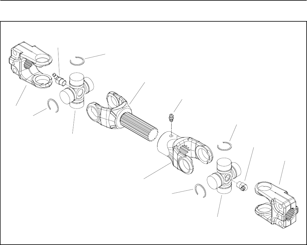
Reelmaster 5010- HHydraulic System Page 4 - 72
Hydraulic Pump Drive Shaft Cross and Bearing Service
1. End yoke (motor/generator)
2. Grease fitting (2 used)
3. Snap ring (4 per cross and bearing)
4. Cross and bearing assembly
5. Shaft yoke (male)
6. Grease fitting
7. Telescoping yoke (female)
8. End yoke (piston pump)
Figure 64
2
3
6
1
5
7
42
3
3
3
4
8

Reelmaster 5010- H Hydraulic SystemPage 4 - 73
Disassembly (Fig. 64)
1. Remove hydraulic pump drive shaft from vehicle
(see Hydraulic Pump Drive Shaft in this section).
IMPORTANT: When placing yoke in vise, clamp
lightly on the solid part of the yoke to prevent yoke
damage. Also, the use of a vise with soft jaws is rec-
ommended.
2. Lightly clamp drive shaft yoke in vise. Use two screw-
drivers to remove snap rings that secure bearings at the
inside of each yoke. Remove yoke from vise.
IMPORTANT: Yokes must be supported when re-
moving and installing bearings to prevent damage.
3. Use a press to remove cross and bearings from
yokes:
A. Place a small socket against one bearing and a
large socket against the yoke on the opposite side.
B. While supporting the large socket, apply pres-
sure on small socket to partially push the opposite
bearing into the large socket.
C. Remove yoke from press, grasp partially re-
moved bearing and tap on yoke to completely re-
move the bearing.
D. Repeat process for remaining bearings.
4. Thoroughly clean and inspect all components.
Assembly (Fig. 64)
1. To install new cross and bearings:
A. Apply a coating of grease to bearing bores of end
yoke and shaft yoke. Also, apply grease to bearings
and seal of bearing assembly. Make sure that all
bearing rollers are properly seated in bearing cage.
B. Press one bearing partially into yoke.
IMPORTANT: Take care when installing cross
into bearing to avoid damaging bearing seal.
C. Carefully insert cross into bearing and yoke.
D. Hold cross in alignment and press bearing in until
it hits the yoke.
E. Carefully place second bearing into yoke bore
and onto cross shaft. Press bearing into yoke.
F. Install snap rings to bearings to secure bearings
in place.
G. Repeat procedure for other yoke.
H. Grease cross until grease comes out of all four (4)
bearing cups.
2. Make sure that assembled joint moves without bind-
ing. Slight binding can usually be eliminated by lightly
rapping the yoke lugs with a soft faced hammer. If bind-
ing continues, disassemble joint to identify source of
binding.
3. Install hydraulic pump drive shaft to vehicle (see Hy-
draulic Pump Drive Shaft in this section).
Hydraulic
System
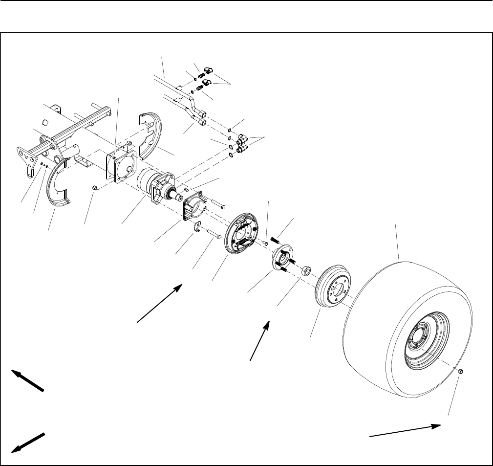
Reelmaster 5010- HHydraulic System Page 4 - 74
Front Wheel Motors
1. Wheel motor (LH shown)
2. Lug nut (5 used per wheel)
3. Hub
4. Wheel stud (5 used per wheel)
5. Wheel assembly
6. Brake drum
7. Front wheel shield (2 used)
8. Cap screw (2 used per shield)
9. Flat washer (2 used per shield)
10. Lock nut (2 used per shield)
11. Rear wheel shield (LH shown)
12. Lock nut
13. Square key
14. Brake assembly (LH shown)
15. Cap screw (4 used per brake assy)
16. Cap screw (4 used per motor)
17. Spring clip (LH shown)
18. Lock nut (4 used per motor)
19. Brake adapter
20. O- ring
21. 90ohydraulic fitting
22. O- ring
23. Hydraulic tube
24. Hydraulic tube
25. Dust cap
26. Test fitting
27. O- ring
Figure 65
FRONT
RIGHT
70 to 90 ft- lb
(95 to 122 N- m)
2
3
1
45
6
8
9
10
11
13
7
12
14
15
16
17
18
19
25
27
26
21
20
22
26
23
24
80 to 100 ft- lb
(109 to 135 N- m)
(428 to 522 N- m)
315 to 385 ft- lb

Reelmaster 5010- H Hydraulic SystemPage 4 - 75
Removal (Fig. 65)
1. Park the machine on a level surface, lower the cut-
ting units and stop the engine. Remove the key from the
ignition switch.
2. Chock rear wheels to prevent machine from moving
or shifting.
3. Read the General Precautions for Removing and
Installing Hydraulic System Components at the begin-
ning of the Service and Repairs section of this chapter.
4. Remove front wheel, brake drum, wheel hub and
brake assembly from machine (see Brake Service in the
Service and Repairs section of Chapter 6 - Chassis).
CAUTION
Before opening hydraulic system, operate all hy-
draulic controls to relieve system pressure and
avoid injury from pressurized hydraulic oil. See
Relieving Hydraulic System Pressure in the Gen-
eral Information section of this chapter.
5. Thoroughly clean hydraulic tube ends and fittings on
wheel motor to prevent hydraulic system contamination.
6. Label hydraulic connections at wheel motor for as-
sembly purposes.
7. Disconnect hydraulic tubes from fittings on wheel
motor. Allow tubes to drain into a suitable container.
8. Put caps or plugs on disconnected tubes and fittings
to prevent contamination.
NOTE: Right and left front wheel motors are the same
basic design with some minor differences. The left side
wheel motor can be identified by the machined groove
on the end of the output shaft. If both motors are re-
moved from the machine, label motors for assembly
purposes.
9. Support wheel motor to prevent it from falling. Re-
move four (4) lock nuts from cap screws that secure mo-
tor and brake adapter to frame.
10.Note location of spring clip (item 17) for assembly
purposes. Remove four (4) cap screws and brake
adapter from wheel motor and frame.
11. Remove wheel motor from machine.
12.If hydraulic fittings are to be removed from wheel mo-
tor, mark fitting orientation to allow correct assembly.
Remove fittings from motor and discard O- rings.
Installation (Fig. 65)
1. If fittings were removed from wheel motor, lubricate
and place new O- rings to fittings. Install fittings into mo-
tor ports using marks made during the removal process
to properly orientate fittings (see Hydraulic Fitting Instal-
lation in the General Information section of this chapter).
2. Position wheel motor and brake adapter to frame. In-
stall spring clip (item 17) and four (4) cap screws to
wheel motor and frame. Make sure that spring clip is po-
sitioned as noted during disassembly.
3. Install and tighten four (4) lock nuts onto cap screws
to secure motor and brake bracket to frame. Torque lock
nuts from 80 to 100 ft- lb (109 to 135 N- m).
4. Remove caps and plugs from disconnected hydrau-
lic tubes and fittings.
5. Lubricate and position new O- rings to fittings on
wheel motor. Use labels placed during the removal pro-
cess to properly install and secure hydraulic tubes to
wheel motor fittings (see Hydraulic Hose and Tube In-
stallation in the General Information section of this chap-
ter)
6. Install brake assembly, wheel hub, brake drum and
front wheel to machine (see Brake Service in the Service
and Repairs section of Chapter 6 - Chassis).
7. Make sure that wheel hub lock nut (item 12) is tight-
ened from 315to385ft-lb(428to522N-m)and wheel
lug nuts are tightened from 70 to 90 ft- lb (95 to 122
N-m).
8. Check and adjust oil level in hydraulic reservoir.
IMPORTANT: If a wheel motor failure occurred, refer
to Traction Circuit Component Failure in the Gener-
al Information section for information regarding the
importance of removing contamination from the
traction circuit.
9. Operate machine functions slowly until air is out of
system (see Charge Hydraulic System in this section).
Hydraulic
System
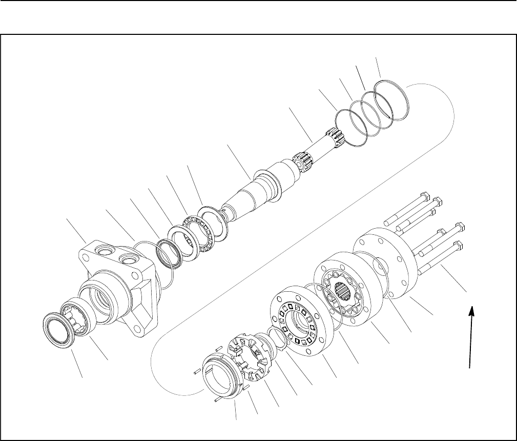
Reelmaster 5010- HHydraulic System Page 4 - 76
Front Wheel Motor Service
1. Cap screw (7 used)
2. End cap
3. O- ring (3 used)
4. Geroler assembly
5. Valve plate
6. Thrust bearing
7. Bearing
8. Valve
9. Dowel pin (4 used)
10. Balancing ring
11. Valve spring
12. Back- up ring
13. O- ring
14. Drive
15. Output shaft
16. Bearing race (2 used)
17. Thrust bearing
18. Shaft seal
19. Housing
20. Bearing
21. Grease seal
Figure 66
(61to75N-m)
45 to 55 ft- lb
2
3
6
8
9
10
11
13
1
5
7
12
14
15
16
17
18
19
20
4
21
3
3
12
16
NOTE: The front wheel motors are Eaton Delta motors
of the same basic design with minor differences. The
right side motor has a reverse timed manifold to allow
correct rotation direction for forward and reverse. The
left side wheel motor can be identified by the machined
groove on the end of the output shaft.
NOTE: For front wheel motor repair procedures, see
the Eaton Delta Motors Parts and Repair Manual at the
end of this chapter.
IMPORTANT: If a wheel motor failure occurred, refer
to Traction Circuit Component Failure in the Gener-
al Information section for information regarding the
importance of removing contamination from the
traction circuit.

Reelmaster 5010- H Hydraulic SystemPage 4 - 77
This page is intentionally blank.
Hydraulic
System
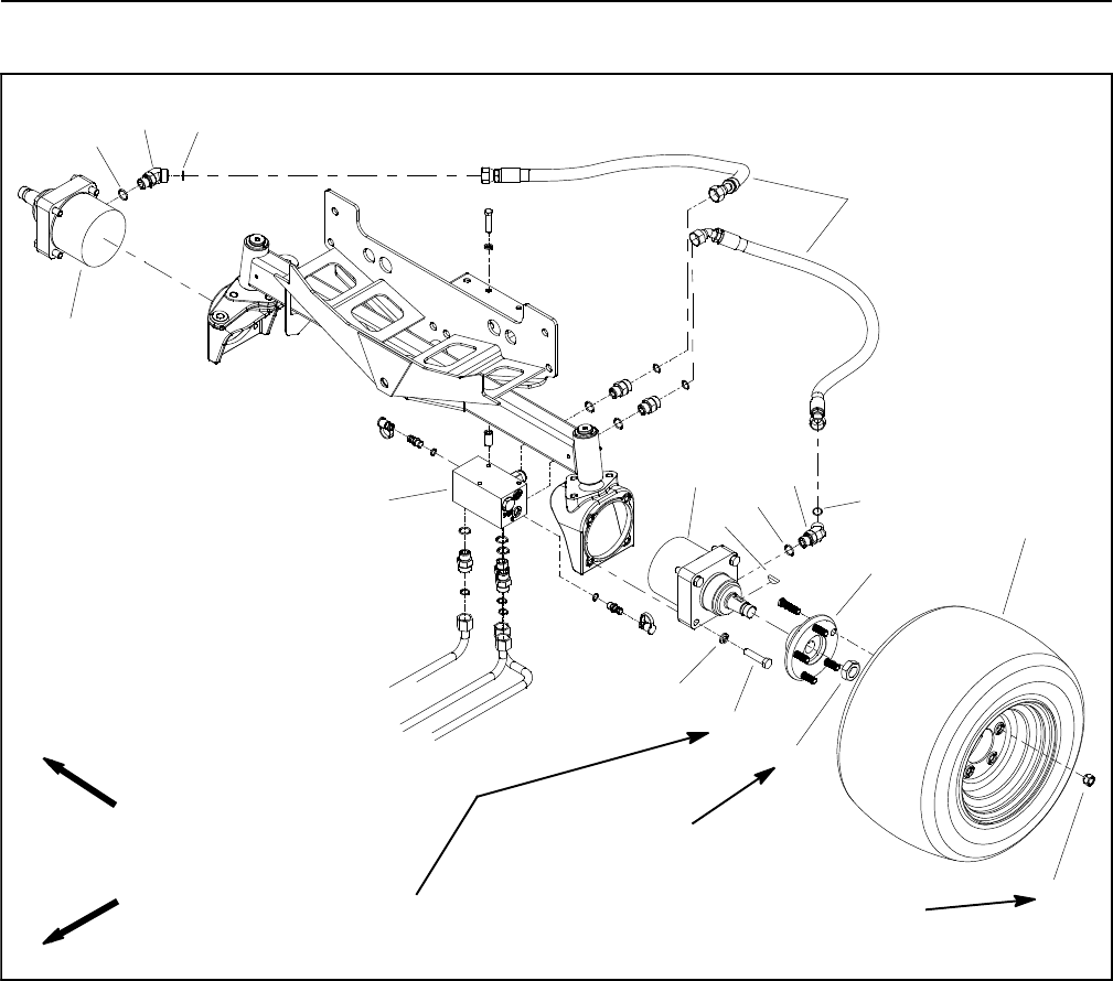
Reelmaster 5010- HHydraulic System Page 4 - 78
Rear Wheel Motors (Machines with Optional CrossTraxTM Kit)
1. Lug nut (5 used per wheel)
2. Rear wheel assembly
3. Wheel hub assembly
4. Lock nut
5. Woodruff key
6. 45ohydraulic fitting (2 per motor)
7. O- ring
8. O- ring
9. Hydraulic hose (4 used)
10. Cap screw (4 per motor)
11. Lock washer (4 per motor)
12. LH rear wheel motor
13. RH rear wheel motor
14. CrossTraxTM control manifold
Figure 67
2
3
6
8
9
10
11
13
1
5
7
12
14
4
68
7
70 to 90 ft- lb
(95 to 122 N- m)
(367 to 447 N- m)
270 to 330 ft- lb
FRONT
RIGHT
70 to 80 ft- lb
(95 to 108 N- m)
Removal (Fig. 67)
1. Park the machine on a level surface, lower the cut-
ting units and stop the engine. Remove the key from the
ignition switch.
2. Chock rear wheels to prevent machine from moving
or shifting.
3. Read the General Precautions for Removing and
Installing Hydraulic System Components at the begin-
ning of the Service and Repairs section of this chapter.
4. Loosen, but do not remove, lock nut (item 4) from
rear wheel motor shaft.
5. Remove rear wheel from machine (see Wheels in
the Service and Repairs section of Chapter 6 - Chas-
sis).

Reelmaster 5010- H Hydraulic SystemPage 4 - 79
6. Remove wheel hub from rear wheel motor:
IMPORTANT: DO NOT hit wheel hub, puller or wheel
motor with a hammer during wheel hub removal or
installation. Hammering may cause damage to the
wheel motor.
A. Make sure that lock nut (item 4) on wheel motor
shaft is loose. Use hub puller (see Special Tools in
this chapter) to loosen wheel hub from wheel motor
shaft.
B. Remove lock nut and wheel hub from wheel mo-
tor shaft. Locate and retrieve woodruff key (item 5).
CAUTION
Before opening hydraulic system, operate all hy-
draulic controls to relieve system pressure and
avoid injury from pressurized hydraulic oil. See
Relieving Hydraulic System Pressure in the Gen-
eral Information section of this chapter.
7. Thoroughly clean hydraulic hose ends and fittings on
wheel motor to prevent hydraulic system contamination.
8. Label hydraulic connections at wheel motor for as-
sembly purposes.
9. Disconnect hydraulic hoses from fittings on wheel
motor. Allow hoses to drain into a suitable container.
10.Put caps or plugs on disconnected hoses and fittings
to prevent contamination.
NOTE: Right and left rear wheel motors are the same
basic design with some minor differences. The left side
wheel motor is identified with a yellow dot on the motor
housing near the B port. If both motors are removed
from the machine, label motors for assembly purposes.
11.Support wheel motor to prevent it from falling. Re-
move four (4) cap screws and lock washers that secure
motor to housing.
12.Remove rear wheel motor from machine.
13.If hydraulic fittings are to be removed from wheel mo-
tor, mark fitting orientation to allow correct assembly.
Remove fittings from motor and discard O- rings.
Installation (Fig. 67)
1. If fittings were removed from wheel motor, lubricate
and place new O- rings to fittings. Install fittings into mo-
tor ports using marks made during the removal process
to properly orientate fittings (see Hydraulic Fitting Instal-
lation in the General Information section of this chapter).
2. Position rear wheel motor to housing. Secure wheel
motor to housing with four (4) cap screws and lock wash-
ers. Torque cap screws from 70 to 80 ft- lb (95 to 108
N-m).
3. Remove caps and plugs from disconnected hydrau-
lic hoses and fittings.
4. Lubricate and position new O- rings to fittings on
wheel motor. Use labels placed during the removal pro-
cess to properly install and secure hydraulic hoses to
wheel motor fittings (see Hydraulic Hose and Tube In-
stallation in the General Information section of this chap-
ter)
IMPORTANT: Before wheel hub is installed, thor-
oughly clean tapers of wheel hub and wheel motor
shaft. Make sure that tapers are free of grease, oil
and dirt. DO NOT use antiseize lubricant when
installing wheel hub.
5. Install woodruff key (item 5) and then wheel hub
(item 3) to wheel motor shaft. Secure wheel hub to the
wheel motor shaft with lock nut (item 4).
6. Install rear wheel to machine (see Wheels in the Ser-
vice and Repairs section of Chapter 6 - Chassis).
7. Make sure that wheel hub lock nut (item 5) is tight-
ened from 270to330ft-lb(367to447N-m)and wheel
lug nuts are tightened from 70 to 90 ft- lb (95 to 122
N-m).
8. Check and adjust oil level in hydraulic reservoir.
IMPORTANT: If a rear wheel motor failure occurred,
refer to Traction Circuit Component Failure in the
General Information section for information regard-
ing the importance of removing contamination from
the traction circuit.
9. Operate machine functions slowly until air is out of
system (see Charge Hydraulic System in this section).
Hydraulic
System
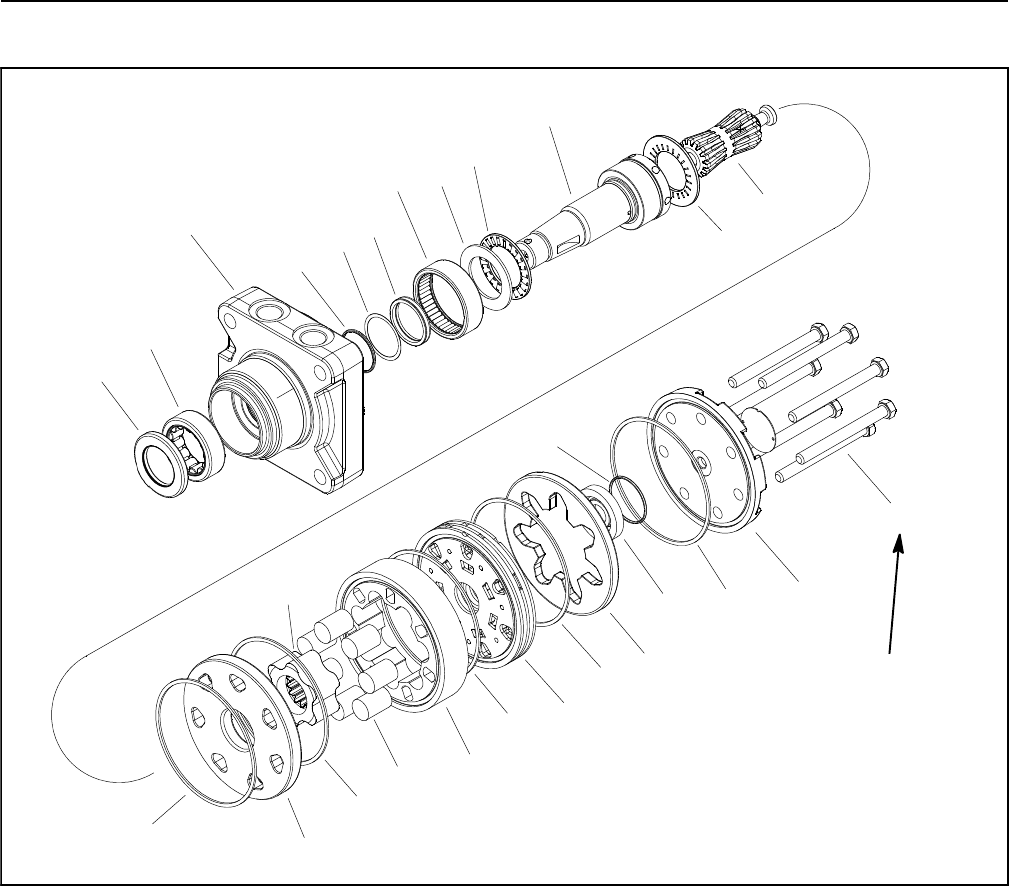
Reelmaster 5010- HHydraulic System Page 4 - 80
Rear Wheel Motor Service (Machines with Optional CrossTraxTM Kit)
1. Cap screw (7 used)
2. End cover
3. Body seal (5 used)
4. Commutator ring
5. Commutator
6. Commutator ring
7. Manifold
8. Stator
9. Vane (7 used)
10. Rotor
11. Wear plate
12. Drive link
13. Thrust bearing
14. Coupling shaft
15. Thrust bearing
16. Thrust washer
17. Inner bearing
18. Shaft seal
19. Back- up washer
20. Back- up ring
21. Housing
22. Outer bearing
23. Dirt and water seal
Figure 68
(61 to 75 N- m)
45 to 55 ft- lb
4
3
1
2
9
10
11
8
5
6
7
12
3
3
3
3
13
14
15
16
17
18
19
20
21
22
23
NOTE: The rear wheel motors used on machines with
the optional CrossTraxTM Kit are Parker TorqmotorTM
motors of the same basic design with minor differences.
The right side motor has a reverse timed manifold to al-
low correct rotation direction for forward and reverse.
The left side wheel motor is identified with a yellow dot
on the motor housing near the B port.
NOTE: For Parker wheel motor repair procedures, see
the Parker TorqmotorTM Service Procedure (TC, TB,
TE, TJ, TF, TG, TH and TL Series) at the end of this
chapter.
IMPORTANT: If a wheel motor failure occurred, refer
to Traction Circuit Component Failure in the Gener-
al Information section for information regarding the
importance of removing contamination from the
traction circuit.
Reelmaster 5010- H Hydraulic SystemPage 4 - 81
Control Manifold Cartridge Valve Service
1. Make sure the control manifold is clean before re-
moving the cartridge valve from the control manifold.
2. If cartridge valve is solenoid operated, remove nut
securing solenoid coil to the cartridge valve. Carefully
slidecoiloffthevalve.
IMPORTANT: Use care when handling the cartridge
valve. Slight bending or distortion of the stem tube
can cause binding and malfunction. When remov-
ing cartridge valve from manifold, make sure that
deep well socket fully engages the valve base.
3. Remove cartridge valve from manifold using a deep
socket wrench. Note correct location for O- rings, seal-
ing rings and backup rings. Remove seal kit from car-
tridge valve and discard removed seals.
4. Visually inspect the port in the manifold for damage
to the sealing surfaces, damaged threads and contami-
nation.
5. Visually inspect cartridge valve for damaged sealing
surfaces and contamination.
A. Contamination may cause valves to stick or hang
up. Contamination can become lodged in small valve
orifices or seal areas causing malfunction.
B. If valve sealing surfaces appear pitted or dam-
aged, the hydraulic system may be overheating or
there may be water in the system.
CAUTION
Use eye protection such as goggles when using
compressed air for cleaning manifold compo-
nents.
6. Clean cartridge valve using clean mineral spirits.
Submerge valve in clean mineral spirits to flush out con-
tamination. Particles as fine as talcum powder can affect
the operation of high pressure hydraulic valves. If car-
tridge design allows, use a wood or plastic probe to push
the internal spool in and out 20 to 30 times to flush out
contamination. Be extremely careful to not damage car-
tridge. Use compressed air for cleaning.
7. Install the cartridge valve into the manifold:
A. Lubricate new seal kit components with clean hy-
draulic oil and install on valve. The O- rings, sealing
rings and backup rings must be arranged properly on
the cartridge valve for proper operation and sealing.
B. Dip assembled cartridge into clean hydraulic oil.
IMPORTANT: Use care when handling the valve
cartridge. Slight bending or distortion of the
stem tube can cause binding and malfunction.
When installing cartridge valve into manifold,
make sure that deep well socket fully engages
the valve base.
C. Thread cartridge valve carefully into manifold
port by hand until the top O- ring is met. The valve
should go into manifold port easily without binding.
D.Torquecartridgevalveusingadeepsocket
wrench to value identified in control manifold illustra-
tion.
8. If cartridge valve is solenoid operated, carefully
install solenoid coil to the cartridge valve. Secure coil to
valve with nut and torque nut to 60 in- lb (6.8 N- m).
9. If problems still exist after assembly, remove valve
and clean again or replace valve.
Hydraulic
System
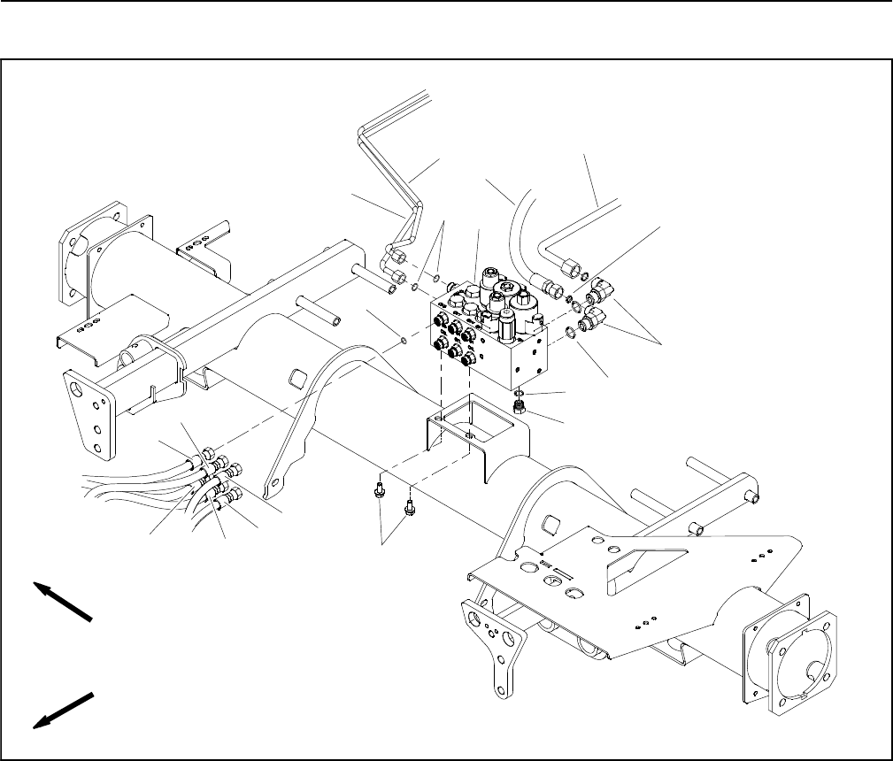
Reelmaster 5010- HHydraulic System Page 4 - 82
Lift Control Manifold
1. Lift control manifold
2. Flange head screw
3. O- ring
4. Hydraulic hose
5. Hydraulic hose
6. Hydraulic hose
7. Hydraulic hose
8. Hydraulic hose
9. Hydraulic hose
10. Hydraulic tube
11. Hydraulic tube
12. O- ring
13. O- ring
14. 90ohydraulic fitting (2 used)
15. O- ring
16. Hydraulic tube
17. Hydraulic hose
18. Plug
19. O- ring
Figure 69
FRONT
RIGHT
2
3
6
8
9
10
11
13
1
5
7
12
14
15
16
17
4
18
19
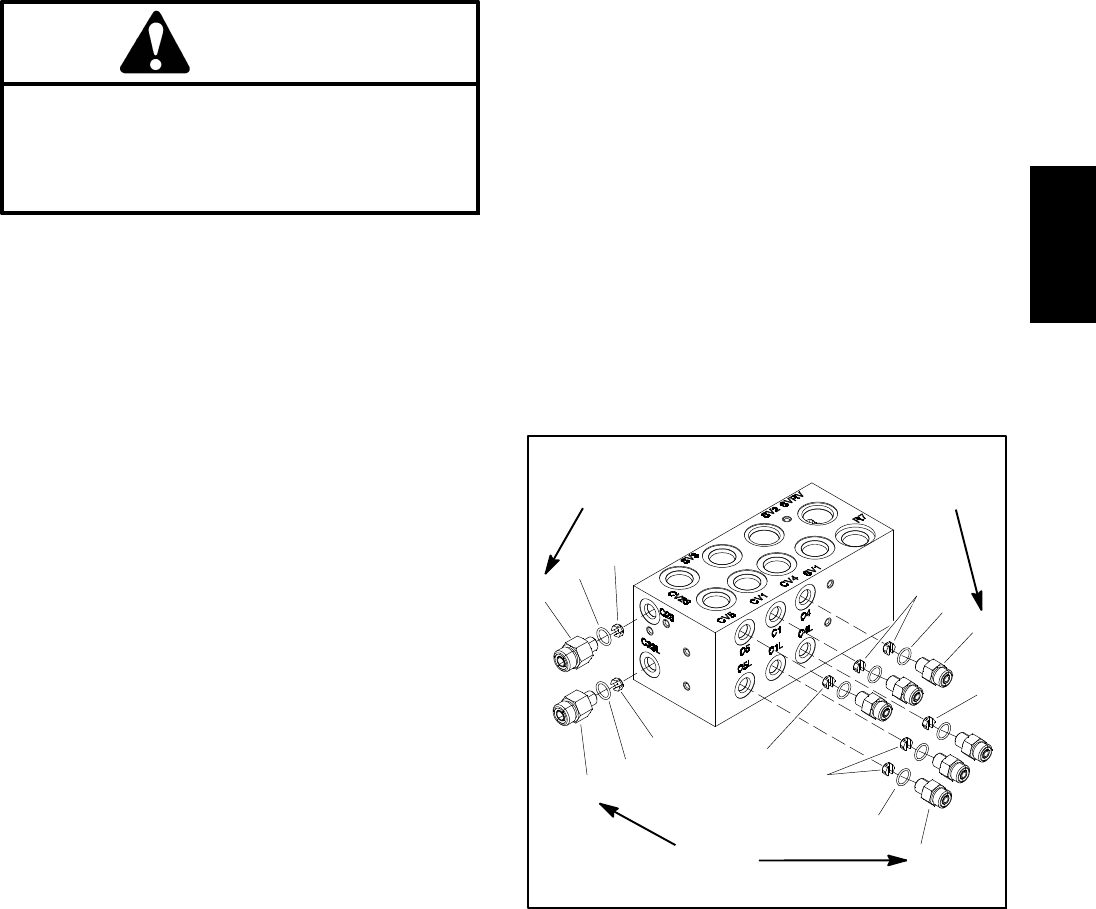
Reelmaster 5010- H Hydraulic SystemPage 4 - 83
Removal (Fig. 69)
1. Park the machine on a level surface, engage parking
brake, lower cutting units and stop engine. Remove key
from the ignition switch.
2. Read the General Precautions for Removing and
Installing Hydraulic System Components at the begin-
ning of the Service and Repairs section of this chapter.
3. Locate hydraulic lift control manifold that is attached
to frame bracket under the front platform.
4. Label all hydraulic connections for assembly pur-
poses. Thoroughly clean hydraulic connections prior to
loosening hydraulic lines.
CAUTION
Before opening hydraulic system, operate all hy-
draulic controls to relieve system pressure and
avoid injury from pressurized hydraulic oil. See
Relieving Hydraulic System Pressure in the Gen-
eral Information section of this chapter.
5. Disconnect hydraulic hoses and tubes from fittings in
manifold. Allow lines to drain into a suitable container.
Remove and discard O- rings.
6. Put caps or plugs on disconnected hydraulic lines
and fittings to prevent contamination.
7. Label all solenoid coil wire harness leads for as-
sembly purposes. Unplug wire harness leads from sole-
noid coils on manifold.
8. Remove two (2) flange head screws that secure
manifold to machine frame.
9. Remove lift control manifold from machine.
IMPORTANT: A flow control orifice is placed be-
neath several hydraulic fittings on the lift control
manifold (Fig. 70). The lift manifold uses three (3)
different orifice sizes. If fittings are removed from
manifold and an orifice is in the manifold port, make
sure to remove orifice and label its position for as-
sembly purposes.
10.If necessary, remove hydraulic fittings from manifold.
Discard any removed O- rings. Locate, retrieve and la-
bel orifice from manifold ports (if equipped).
Installation (Fig. 69)
1. If fittings were removed from manifold:
A. Lubricate new O- rings with clean hydraulic oil.
Install lubricated O- rings on fittings.
IMPORTANT: When installing orifice in manifold
(Fig. 70), make sure that orifice is flat in the base
of the fitting cavity. Manifold damage is possible
if the orifice is cocked in the cavity.
B. For manifold ports with orifice, place correct ori-
fice in port with the orifice slot facing out.
C. Install fittings into manifold (see Hydraulic Fitting
Installation in the General Information section of this
chapter). Torque fittings to torque values identified in
Figure 70.
2. Position lift control manifold to frame. Install two (2)
flange head screws but do not fully tighten.
3. Remove caps and plugs from hydraulic lines and fit-
tings.
4. Lubricate and install new O- ring(s) on manifold fit-
tings. Connect and tighten hydraulic lines to hydraulic
manifold fittings (see Hydraulic Hose and Tube Installa-
tion in the General Information section of this chapter)
5. Secure hydraulic manifold to frame by tightening two
(2) flange head screws.
6. Connect wire harness leads to solenoid coils on
manifold using labels placed during removal.
7. Check oil level in hydraulic reservoir and add correct
oil if necessary.
8. Follow Hydraulic System Start- up procedures (see
Hydraulic System Start- up in this section).
1. Fitting (2 used)
2. O- ring
3. Orifice (0.046)
4. Orifice (0.028)
5. Fitting (6 used)
6. Orifice (0.055)
Figure 70
4
1
2
5
3
1
2
3
4
2
2
6
6
5
(14 N- m)
10 ft- lb
(14 N- m)
10 ft- lb
(14 N- m)
10 ft- lb
Hydraulic
System
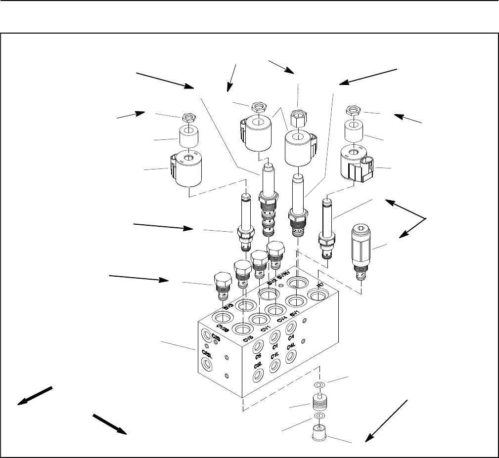
Reelmaster 5010- HHydraulic System Page 4 - 84
Lift Control Manifold Service
1. Lift control manifold
2. Check valve (4 used)
3. Solenoid valve (SV3)
4. Solenoid coil (2 used)
5. Solenoid coil spacer (2 used)
6. Nut (3 used)
7. Solenoid valve (SV2)
8. Solenoid coil (2 used)
9. Nut
10. Solenoid relief valve (SVRV)
11. Solenoid valve (SV1)
12. Relief valve (R7)
13. O- ring
14. Pilot piston (4 used)
15. O- ring
16. Hex plug (4 used)
Figure 71
FRONT
RIGHT
4
3
1
2
9
10
11
8
5
6
7
12
4
5
6
6
13
14
15
16
(33 N- m)
25 ft- lb
(27 N- m)
20 ft- lb
(27 N- m)
20 ft- lb
(101 N- m)
75 ft- lb
(27 N- m)
20 ft- lb
(33 N- m)
25 ft- lb
60 in- lb
(6.7 N- m)
60 in- lb
(6.7 N- m)
60 in- lb
(6.7 N- m)
NOTE: The ports on the lift control manifold are marked
for easy identification of components. Example: P4 is
the gear pump connection port and SV2 is the location
for solenoid valve SV2 (see Hydraulic Schematic to
identify the function of the hydraulic lines and cartridge
valves at each port location).
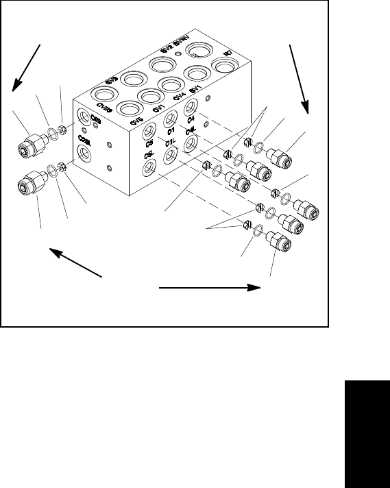
Reelmaster 5010- H Hydraulic SystemPage 4 - 85
For lift control manifold service procedures, see Control
Manifold Cartridge Valve Service in this section. Refer
to Figure 71 for cartridge valve installation torque. Refer
to Figures 71 and 72 for hydraulic fitting installation
torque values.
NOTE: Solenoid valves SV1 and SV2 on the lift control
manifold use a coil spacer between the solenoid coil and
nut.
NOTE: Adjustment of Relief Valve (R7) is NOT recom-
mended.
IMPORTANT: A flow control orifice is placed be-
neath several of the hydraulic fittings on the lift con-
trol manifold (Fig. 72). The lift manifold uses three
(3) different orifice sizes. If a fitting is removed from
the lift control manifold and an orifice is in the man-
ifold port, make sure to remove orifice and label its
position for assembly purposes.
IMPORTANT: When installing orifice in manifold
(Fig. 72), make sure that orifice is flat in the base of
the fitting cavity. Manifold damage is possible if the
orifice is cocked in the cavity.
1. Fitting (2 used)
2. O- ring
3. Orifice (0.046)
4. Orifice (0.028)
5. Fitting (6 used)
6. Orifice (0.055)
Figure 72
4
1
2
5
3
1
2
3
4
2
2
6
6
5
(14 N- m)
10 ft- lb
(14 N- m)
10 ft- lb
(14 N- m)
10 ft- lb
Hydraulic
System
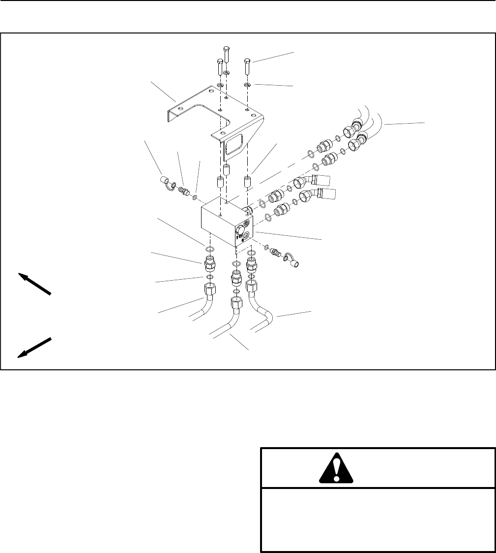
Reelmaster 5010- HHydraulic System Page 4 - 86
CrossTraxTM AWD Manifold (Machines with Optional CrossTraxTM Kit)
1. CrossTrax AWD manifold
2. Hydraulic tube
3. Hydraulic tube
4. Hydraulic tube
5. O- ring
6. Hydraulic fitting (7 used)
7. O- ring
8. Dust cap (2 used)
9. Diagnostic fitting (2 used)
10. O- ring
11. Cap screw (3 used)
12. Lock washer (3 used)
13. Spacer (3 used)
14. Hydraulic hose (4 used)
15. Frame bracket
Figure 73
FRONT
RIGHT 4
3
1
2
910
11
8
5
6
7
12
13
14
15
Removal (Fig. 73)
1. Park the machine on a level surface, engage parking
brake, lower cutting units and stop engine. Remove key
from the ignition switch.
2. Read the General Precautions for Removing and
Installing Hydraulic System Components at the begin-
ning of the Service and Repairs section of this chapter.
3. Locate CrossTraxTM AWD manifold that is attached
tobracketatrearofframe.
4. Label all hydraulic connections for assembly pur-
poses. Thoroughly clean hydraulic connections prior to
loosening hydraulic lines.
CAUTION
Before opening hydraulic system, operate all hy-
draulic controls to relieve system pressure and
avoid injury from pressurized hydraulic oil. See
Relieving Hydraulic System Pressure in the Gen-
eral Information section of this chapter.
5. Disconnect hydraulic hoses and tubes from fittings in
manifold. Allow lines to drain into a suitable container.
Remove and discard O- rings.

Reelmaster 5010- H Hydraulic SystemPage 4 - 87
6. Put caps or plugs on disconnected lines and fittings
to prevent contamination.
7. Support manifold to prevent it from falling. Remove
three (3) cap screws and lock washers that secure man-
ifold to machine frame. Locate and retrieve three (3)
spacers from between frame bracket and manifold.
8. Remove AWD manifold from machine.
9. If necessary, remove hydraulic fittings from manifold.
Discard any removed O- rings.
Installation (Fig. 73)
1. If fittings were removed from AWD manifold, lubri-
cate and place new O- rings to fittings. Install fittings into
manifold (see Hydraulic Fitting Installation in the Gener-
al Information section of this chapter).
2. Position manifold and three (3) spacers to frame
bracket. Install three (3) lock washers and cap screws
but do not fully tighten.
3. Remove caps and plugs from disconnected hy-
draulic lines and fittings.
4. Lubricate and install new O- ring(s) on manifold fit-
tings. Connect hydraulic lines to hydraulic manifold fit-
tings. Properly tighten all connections (see Hydraulic
Hose and Tube Installation in the General Information
section of this chapter).
5. Secure AWD manifold to frame by tightening three
(3) cap screws.
6. Check oil level in hydraulic reservoir and add correct
oil if necessary.
7. Follow hydraulic system start- up procedures (see
Hydraulic System Start- up in this section).
Hydraulic
System
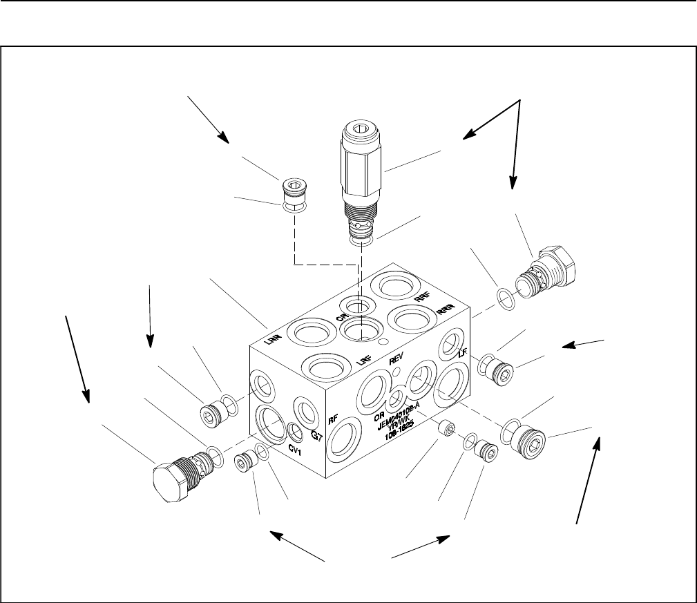
Reelmaster 5010- HHydraulic System Page 4 - 88
CrossTraxTM AWD Manifold Service (Machines with Optional CrossTraxTM Kit)
1. CrossTrax AWD manifold
2. O- ring
3. Plug (NWD #6)
4. Seal kit
5. Check valve
6. Plug (NWD #4)
7. O- ring
8. Orifice (.040)
9. Plug (NWD #8)
10. O- ring
11. Seal kit
12. Bi- Directional relief valve
Figure 74
4
3
1
2
9
10
11
8
5
6
7
12
2
2
3
3
4
5
6
7
(33 N- m)
25 ft- lb
(33 N- m)
25 ft- lb
120 in- lb
(13.5 N- m)
(62 N- m)
46 ft- lb
220 in- lb
(24.8 N- m)
220 in- lb
(24.8 N- m)
220 in- lb
(24.8 N- m)
For CrossTraxTM AWD control manifold service proce-
dures, see Control Manifold Cartridge Valve Service in
this section. Refer to Figure 74 for cartridge valve and
plug installation torque.
NOTE: Adjustment of bi- directional relief valve (item
12) is NOT recommended.

Reelmaster 5010- H Hydraulic SystemPage 4 - 89
This page is intentionally blank.
Hydraulic
System
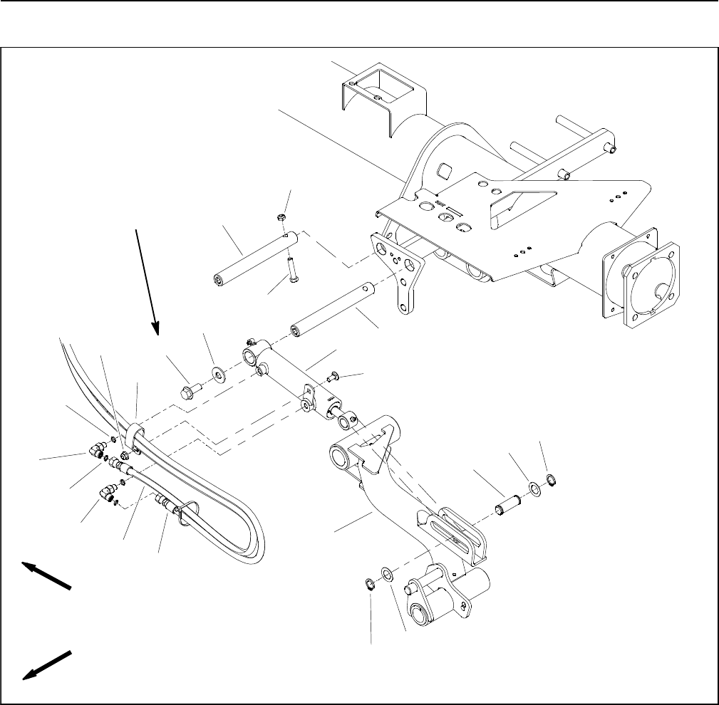
Reelmaster 5010- HHydraulic System Page 4 - 90
Lift Cylinders
1. Lift cylinder
2. Cylinder pin
3. Flange head screw
4. Lift arm (#4 shown)
5. Flat washer
6. Hydraulic hose
7. O- ring
8. 90ohydraulic fitting
9. O- ring
10. Hydraulic hose
11. Retaining ring
12. Thrust washer
13. Cylinder slide pin
14. Carriage screw
15. Flange nut
16. R- clamp
17. Cap screw
18. Lock nut
Figure 75
FRONT
RIGHT
77 to 93 ft- lb
(105 to 126 N- m) 2
3
6
8
9
10
11
13
1
5
7
12
14
15
16
17
18
4
8
11
12
2
Medium strength
Threadlocker
NOTE: The procedure for lift cylinder removal and
installation is the same for all Reelmaster 5010- H lift cyl-
inders. Figure 75 shows the lift cylinder for the #4 cutting
unit (left front).

Reelmaster 5010- H Hydraulic SystemPage 4 - 91
Removal (Fig. 75)
1. Park the machine on a level surface, engage the
parking brake, lower the cutting units and stop the en-
gine. Remove the key from the ignition switch.
2. To prevent unexpected cutting unit operation, dis-
connect the cutting units from the electrical power sup-
ply by unplugging the 48 VDC battery disconnect (see
48 VDC Battery Disconnect in the General Information
section of this chapter).
3. Read the General Precautions for Removing and
Installing Hydraulic System Components at the begin-
ning of the Service and Repairs section of this chapter.
4. Label all hydraulic connections for assembly pur-
poses. Thoroughly clean hydraulic connections prior to
loosening hydraulic lines from lift cylinder.
5. If lift cylinder for outside front cutting units (#4 or #5)
is being removed, remove flange nut and carriage screw
that secure the hydraulic hose R- clamp to lift cylinder.
CAUTION
Before opening hydraulic system, operate all hy-
draulic controls to relieve system pressure and
avoid injury from pressurized hydraulic oil. See
Relieving Hydraulic System Pressure in the Gen-
eral Information section of this chapter.
WARNING
Make sure that cutting units are fully lowered be-
fore loosening hydraulic lines from lift cylinders.
If cutting units are not fully lowered as hydraulic
lines are loosened, the cutting units may drop
unexpectedly.
6. Disconnect hydraulic hoses from fittings in lift cylin-
der that is to be removed. Allow hoses to drain into a suit-
able container. Remove and discard O- rings.
7. Put caps or plugs on disconnected hoses and fittings
to prevent contamination.
8. Remove one retaining ring (item 11) and thrust wash-
er (item 12) from the cylinder slide pin (item 13) that se-
cures lift cylinder to lift arm. Pull slide pin from the lift
cylinder and lift arm. Locate and retrieve second thrust
washer.
9. Remove flange head screw (item 3) and flat washer
(item 5) that retain lift cylinder to cylinder pin.
10.Slide lift cylinder from cylinder pin and remove from
machine.
11. If hydraulic fittings are to be removed from lift cylin-
der, mark fitting orientation to allow correct assembly.
Remove fittings from lift cylinder and discard O- rings.
Installation (Fig. 75)
1. If hydraulic fittings were removed from lift cylinder, lu-
bricate new O- rings, position O- rings to fittings and
install fittings into lift cylinder ports (see Hydraulic Fitting
Installation in the General Information section of this
chapter). Make sure that fittings are orientated correctly.
2. Position lift cylinder to the frame with the barrel end
up.
3. Slide lift cylinder clevis onto cylinder pin.
4. Apply medium strength threadlocker to threads of
flange head screw (item 3). Secure cylinder with flange
head screw (item 3) and flat washer (item 5). Torque
screw from 77 to 93 ft- lb (105 to 126 N- m).
5. Align lift cylinder to lift arm mounting slot. Slide cylin-
der slide pin (item 13) with retaining ring (item 12) and
thrust washer (item 12) through the lift arm and lift cylin-
der. Install second thrust washer on pin and secure with
second retaining ring.
6. Remove caps and plugs from disconnected hoses
and fittings.
7. Coat new O- rings lightly with clean hydraulic oil,
install new O- rings and connect hydraulic hoses to fit-
tings on lift cylinder. Tighten hose connections (see Hy-
draulic Hose and Tube Installation in the General
Information section of this chapter).
8. Check oil level in hydraulic reservoir and add correct
oil if necessary.
9. Lubricate lift cylinder grease fittings.
10.Plug the cutting unit power disconnect connector
back in before operating the machine.
11. Follow hydraulic system start- up procedures (see
Hydraulic System Start- up in this section).
Hydraulic
System
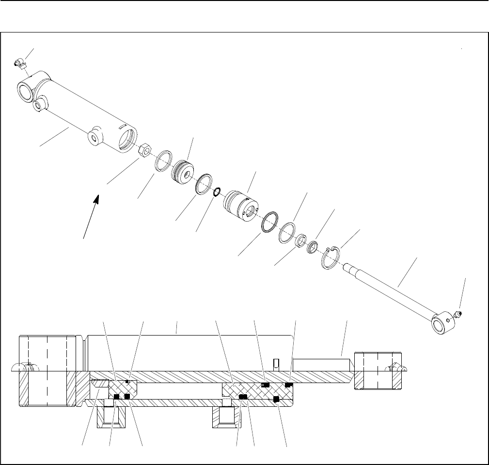
Reelmaster 5010- HHydraulic System Page 4 - 92
Lift Cylinder Service
1. Grease fitting
2. Shaft
3. Dust seal
4. Head
5. BS seal
6. Retaining ring
7. Back up washer
8. O- ring
9. Piston
10. Wear ring
11. BP seal
12. O- ring
13. Lock nut
14. Barrel
15. Grease fitting
Figure 76
2
3
4
5
6
9
8
7
1
10
11
14
12
13
2345
6
9
8710 11
1412
13
15
40 ft- lb
(54 N- m)
NOTE: The front, outside lift cylinders are longer with
more stroke than the other lift cylinders which are identi-
cal. Service procedures for all lift cylinders used on Re-
elmaster 5010- H machines are the same.
Disassembly (Fig. 76)
1. Remove oil from lift cylinder into a drain pan by slowly
pumping the cylinder shaft. Plug both ports and clean
the outside of the cylinder.
IMPORTANT: Prevent damage when clamping the
lift cylinder into a vise; clamp on the clevis end of
the barrel ONLY.
2. Mount lift cylinder securely in a vise by clamping on
the clevis end of the barrel. Use of a vise with soft jaws
is recommended.

Reelmaster 5010- H Hydraulic SystemPage 4 - 93
3. Using a spanner wrench, rotate head clockwise until
the edge of the retaining ring appears in the barrel open-
ing. Insert a screwdriver under the beveled edge of the
retaining ring to start the retaining ring through the open-
ing.Rotatetheheadcounter-clockwisetoremovere-
taining ring from barrel and head.
4. Remove plugs from ports. Extract shaft, head and
piston by carefully twisting and pulling on the shaft.
IMPORTANT: Do not clamp vise jaws against the
shaft surface. Clamp on the clevis ONLY.
5. Mount shaft securely in a vise by clamping on the cle-
vis of the shaft. Remove lock nut and piston from the
shaft. Carefully slide head off the shaft.
6. Taking care to not scratch or damage the piston, re-
move wear ring, BP seal and O- ring from the piston.
7. Taking care to not scratch or damage the head, re-
move O- ring, back- up washer, dust seal and BS seal
from the head.
8. Discard removed seals and O- rings.
Inspection
CAUTION
Use eye protection such as goggles when using
compressed air to clean lift cylinder compo-
nents.
1. Wash all lift cylinder components in solvent. Dry
parts with compressed air.
2. Inspect internal surface of barrel for deep scratches,
out- of- roundness and bending.
3. Inspect head, shaft and piston for excessive pitting,
scoring and wear.
4. Replace lift cylinder if internal components are found
to be worn or damaged.
Assembly (Fig. 76)
1. Make sure all lift cylinder parts are clean before as-
sembly.
2. Coat new O- rings, back- up washer and other seals
with clean hydraulic oil.
A. Carefully install wear ring, BP seal and O- ring to
the piston.
B. Carefully install back- up washer, O- ring, dust
seal and BS seal to the head.
IMPORTANT: Do not clamp vise jaws against the
shaft surface. Clamp on the clevis ONLY.
3. Mount shaft securely in a vise by clamping on the cle-
vis of the shaft.
A. Coat shaft with clean hydraulic oil.
B. Slideheadassemblyontotheshaft.
C. Install piston assembly onto the shaft and secure
with lock nut. Torque lock nut 40 ft- lb (54 N- m).
D. Remove shaft assembly from the vise.
IMPORTANT: Prevent damage when clamping the
hydraulic cylinder into a vise; clamp on the clevis
end of the barrel ONLY.
4. Mount barrel securely in a vise by clamping on the
clevis end of the barrel.
IMPORTANT: When installing the head into the bar-
rel, pay careful attention to the retaining ring slot in
the barrel to insure that the piston and head seals do
not lodge in the slot.
5. Coat all internal parts with a light coat of clean hy-
draulic oil. Slide piston, shaft and head assembly into
the barrel being careful not to damage the seals.
6. Secure head in barrel by installing retaining ring.
A. Align retaining ring hole in the head with the ac-
cess slot in the barrel.
B. Insert the retaining ring hook into the hole and ro-
tate head clockwise until the retaining ring is com-
pletely pulled into the barrel and the ring ends are
covered.
Hydraulic
System
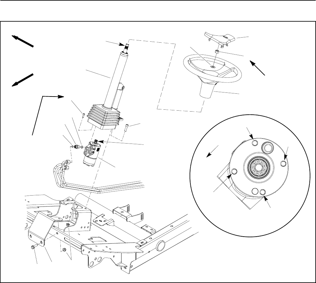
Reelmaster 5010- HHydraulic System Page 4 - 94
Steering Control Valve
1. Steering control valve
2. Flange head screw (2 used)
3. Socket head screw (4 used)
4. Steering wheel
5. Flat washer
6. Lock nut
7. Steering wheel cover
8. Steering column
9. Socket head screw (4 used)
10. O- ring
11. Hydraulic fitting (4 used)
12. O- ring
13. Steeringcolumnbrace
14. Flange nut (6 used)
Figure 77
FRONT
RIGHT
20 to 26 ft lb
(28 to 35 N- m)
Antiseize
Lubricant
4
3
1
9
10
11
8
5
6
7
12
213 14
7to10ft-lb
(9.5 to 13.5 N- m)
Antiseize
Lubricant
1st
2nd
3rd
4th
FRONT
Tightening
Sequence
(Item 9)
Removal (Fig. 77)
1. Park the machine on a level surface, engage the
parking brake, lower the cutting units and stop the en-
gine. Remove the key from the ignition switch.
2. Remove fasteners that secure shroud to front of ma-
chine (Fig. 78). Remove shroud from machine to allow
access to steering control valve. Locate and retrieve two
(2) rubber bushings and spacers.
3. Slide rubber bellows up from bottom of steering col-
umn. Support steering column to prevent it from falling.
4. Loosen and remove four (4) flange head screws and
flange nuts that secure steering column brace (item 13)
to machine. Remove brace.
5. Read the General Precautions for Removing and
Installing Hydraulic System Components at the begin-
ning of the Service and Repairs section of this chapter.
6. Label all hydraulic connections for assembly pur-
poses. Note port designations on steering control valve
(Fig. 79). Thoroughly clean hydraulic connections prior
to loosening hydraulic lines.
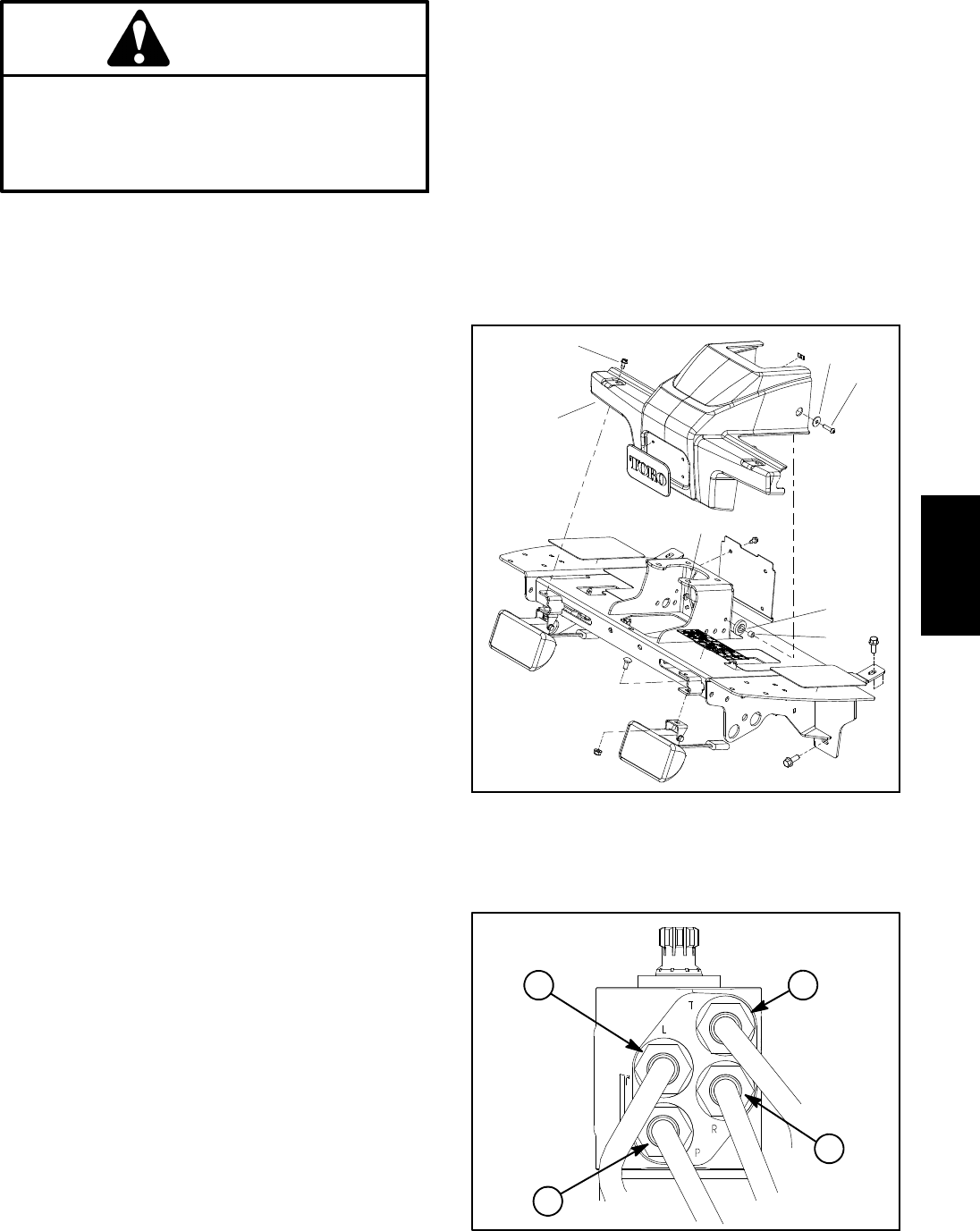
Reelmaster 5010- H Hydraulic SystemPage 4 - 95
CAUTION
Before opening hydraulic system, operate all hy-
draulic controls to relieve system pressure and
avoid injury from pressurized hydraulic oil. See
Relieving Hydraulic System Pressure in the Gen-
eral Information section of this chapter.
7. Disconnect hydraulic lines from steering control
valve. Allow lines to drain into a suitable container.
8. Put caps or plugs on disconnected lines and fittings
to prevent contamination.
9. Remove two (2) socket head screws and flange nuts
that secure steering column to machine.
10.Remove steering column assembly with steering
control valve attached from machine.
11.Loosen and remove four (4) socket head screws that
secure steering control valve to steering column.
12.Remove steering control valve from steering col-
umn.
13.If necessary, remove fittings and O- rings from steer-
ing control valve. Discard all removed O- rings.
Installation (Fig. 77)
1. If fittings were removed, lubricate new O- rings with
clean hydraulic oil and install fittings to steering control
valve (see Hydraulic Fitting Installation in the General
Information section of this chapter).
2. Apply antiseize lubricant to splines of steering con-
trol valve shaft.
3. Slide steering control valve shaft into steering col-
umn universal joint. Position control valve with ports to-
ward front of machine. Secure steering control valve to
steering column with four (4) socket head screws. Hand
tighten screws in the sequence shown in Figure 77.
Then, using the same sequence, torque screws from 7
to 10 ft- lb (9.5 to 13.5 N- m).
4. Position steering column assembly to machine. Se-
cure steering column in place with two (2) socket head
screws and flange nuts at rear two mounting holes.
5. Remove caps and plugs from disconnected lines
and fittings.
6. Lubricate new O- rings and connect hydraulic lines
to fittings on steering control valve. Tighten connections
(see Hydraulic Hose and Tube Installation in the Gener-
al Information section of this chapter).
7. Position steering column brace (item 13) to machine
and secure with four (4) flange head screws and flange
nuts.
8. Slide rubber bellows to bottom of steering column.
9. Place rubber bushings and spacers into holes of
shroud (Fig. 78). Position shroud in place and secure
with removed fasteners.
10.Check oil level in hydraulic reservoir and add correct
oil if necessary.
11. Follow Hydraulic System Start- up procedures (see
Hydraulic System Start- up in this section).
1. Shroud
2. Screw (2 used)
3. Flat washer (2 used)
4. Phillips screw (2 used)
5. Lock nut (2 used)
6. Rubber bushing (2 used
)
7. Spacer (2 used)
Figure 78
4
3
1
2
5
6
7
Figure 79
T
L
P
R
Hydraulic
System
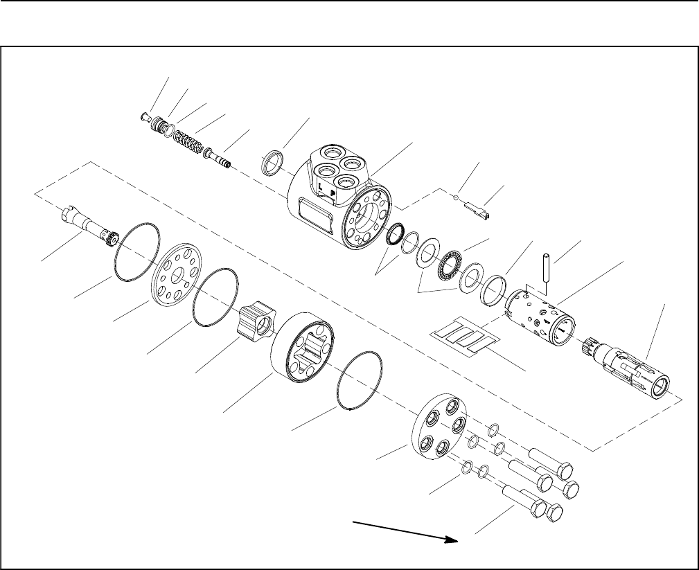
Reelmaster 5010- HHydraulic System Page 4 - 96
Steering Control Valve Service
1. Screw (5 used)
2. O- ring (5 used)
3. End cover
4. O- ring
5. Outer gearwheel
6. Inner gearwheel
7. Distributor plate
8. O- ring
9. Cardan shaft
10. Spool
11. Sleeve
12. Cross pin
13. Spring set
14. Ring
15. Thrust washer
16. Bearing
17. Shaft seal
18. Ball stop
19. Check ball
20. Housing
21. Dust seal ring
22. Relief valve
23. Spring
24. O- ring
25. Plug
26. Plug
Figure 80
2
3
4
5
6
1
9
8
7
10
11
14 12
13
4
15
16
17
18
19
20
21
24
25
22
23
26
20 to 24 ft- lb
(27to33N-m)
NOTE: For repair of the steering control valve, see the
Sauer- Danfoss Steering Unit Type OSPM Service
Manual at the end of this chapter.

Reelmaster 5010- H Hydraulic SystemPage 4 - 97
This page is intentionally blank.
Hydraulic
System
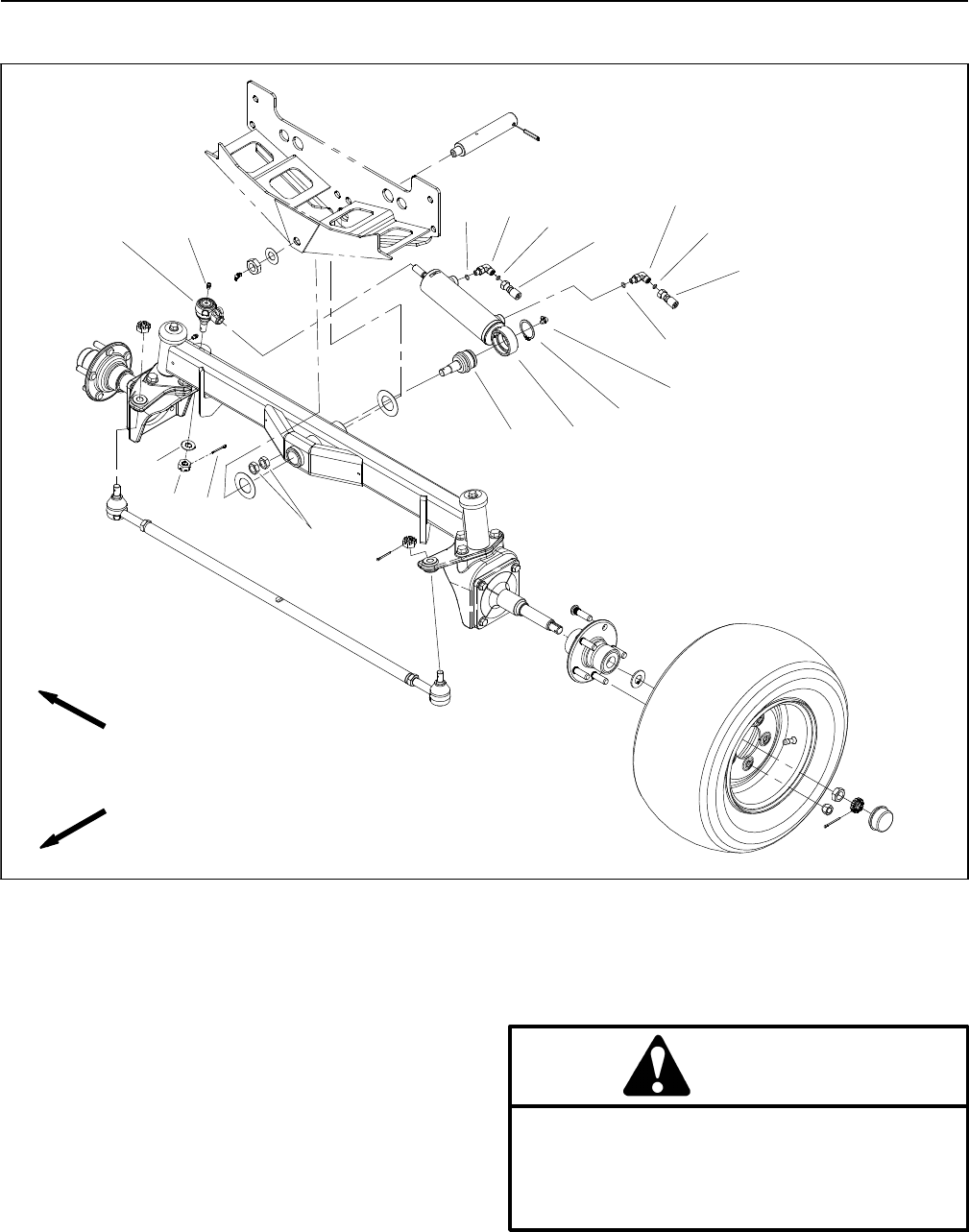
Reelmaster 5010- HHydraulic System Page 4 - 98
Steering Cylinder
1. Steering cylinder
2. Retaining ring
3. Grease fitting
4. Hydraulic hose
5. O- ring
6. 90ohydraulic fitting
7. O- ring
8. Hydraulic hose
9. Grease fitting
10. Ball joint
11. Jam nut
12. Cotter pin
13. Slotted hex nut
14. Washer
15. Ball joint
Figure 81
FRONT
RIGHT
9
10
11
4
3
7
13
2
12
8
67
14
1
5
56
15
Removal (Fig. 81)
1. Park the machine on a level surface, engage the
parking brake, lower the cutting units and stop the en-
gine. Remove the key from the ignition switch.
2. Read the General Precautions for Removing and
Installing Hydraulic System Components at the begin-
ning of the Service and Repairs section of this chapter.
CAUTION
Before opening hydraulic system, operate all hy-
draulic controls to relieve system pressure and
avoid injury from pressurized hydraulic oil. See
Relieving Hydraulic System Pressure in the Gen-
eral Information section of this chapter.
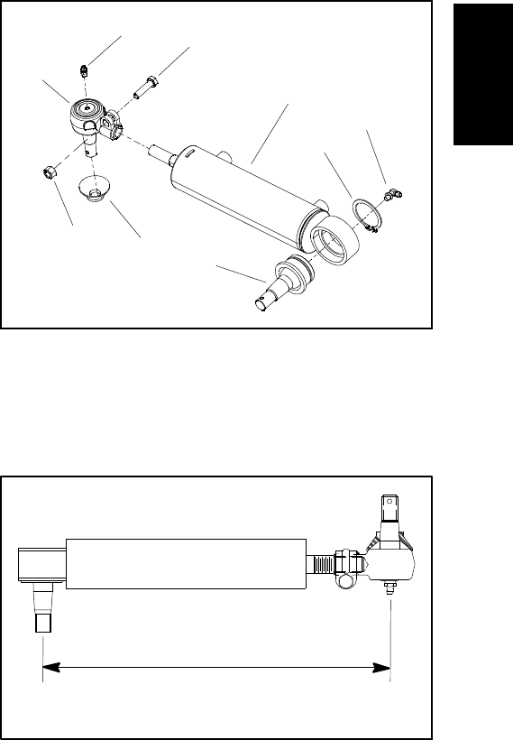
Reelmaster 5010- H Hydraulic SystemPage 4 - 99
3. Label all hydraulic connections for assembly pur-
poses. Thoroughly clean hydraulic hose ends prior to
disconnecting hoses from the steering cylinder.
4. Disconnect hydraulic hoses from fittings in steering
cylinder.
5. Put caps or plugs on disconnected hoses and fittings
to prevent contamination.
6. Remove two (2) jam nuts (item 11) that secure steer-
ing cylinder to axle. Remove cotter pin (item 12), washer
(item 14) and slotted hex nut (item 13) that secure steer-
ing cylinder to RH drag link.
7. Separate ball joints from axle assembly and remove
steering cylinder from machine.
8. If necessary, remove ball joints from steering cylin-
der barrel and shaft (Fig. 82). If ball joint is to be removed
from cylinder shaft, fully retract cylinder shaft and mea-
sure center to center length to ease installation of ball
joint onto cylinder shaft (Fig. 83).
9. If hydraulic fittings are to be removed from steering
cylinder, mark fitting orientation to allow correct assem-
bly. Remove fittings from steering cylinder and discard
O- rings.
Installation (Fig. 81)
1. If hydraulic fittings were removed from steering cylin-
der, lubricate new O- rings with clean hydraulic oil, posi-
tion O- rings to fittings and install fittings into steering
cylinder ports (see Hydraulic Fitting Installation in the
General Information section of this chapter). Make sure
that fittings are orientated correctly.
2. If removed, press ball joint into barrel and secure with
retaining ring. Make sure that retaining ring is fully seat-
ed in groove in steering cylinder barrel.
3. If ball joint was removed from cylinder shaft, fully re-
tract cylinder shaft and thread ball joint onto shaft so that
center to center length is as measured during removal
process. Tighten clamp bolt and nut.
4. Thoroughly clean tapers on ball joints and axle as-
sembly.
5. Position steering cylinder to machine.
6. Secure steering cylinder to axle with jam nuts (item
11). Tighten first jam nut and then, while holding first jam
nut with wrench, tighten second jam nut.
7. Secure steering cylinder to RH drag link with washer
(item 14) and slotted hex nut (item 13). Install cotter pin
(item 12).
8. Remove caps and plugs from hydraulic hoses and
fittings.
9. Lubricate and install new O- rings on steering cylin-
der fittings. Correctly connect hydraulic hoses to steer-
ing cylinder fittings (see Hydraulic Hose and Tube
Installation in the General Information section of this
chapter).
10.Check oil level in hydraulic reservoir and add correct
oil if necessary.
11. Lubricate cylinder ball joint grease fittings.
12.Follow Hydraulic System Start- up procedures (see
Hydraulic System Start- up in this section).
13.Check that steering cylinder does not contact the
axle or frame as cylinder moves from fully retracted to
fully extended. Also, check that distance between the
drag links and steering stops are equal on both sides of
the machine. If necessary, adjust location of ball joint on
cylinder shaft.
1. Steering cylinder
2. Ball joint
3. Retaining ring
4. Grease fitting
5. Ball joint
6. Hex nut
7. Cap screw
8. Seal
9. Grease fitting
Figure 82
1
2
3
4
5
6
7
8
9
Figure 83
MEASURE CENTER TO CENTER LENGTH
FOR ASSEMBLY PURPOSES
Hydraulic
System
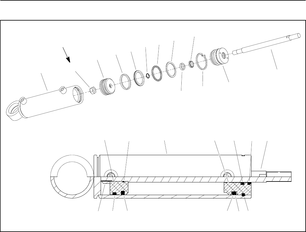
Reelmaster 5010- HHydraulic System Page 4 - 100
Steering Cylinder Service
1. Shaft
2. Dust seal
3. BP seal
4. Head
5. Retaining ring
6. Back- up ring
7. O- ring
8. O- ring
9. Piston
10. BS seal
11. Barrel
12. Wear ring
13. Lock nut
Figure 84
4
6
98
7
11
35
21
12
13
10
40 ft- lb
(54 N- m)
2
4
6
1
9
87
10
11 13
3
5
12
Disassembly (Fig. 84)
1. Remove oil from steering cylinder into a drain pan by
slowly pumping the cylinder shaft. Plug both ports and
clean the outside of the cylinder.
IMPORTANT: Prevent damage when clamping the
steering cylinder into a vise; clamp on the clevis end
of the barrel ONLY.
2. Mount steering cylinder securely in a vise by clamp-
ing on the clevis end of the barrel. Use of a vise with soft
jaws is recommended.
3. Using a spanner wrench, rotate head clockwise until
the edge of the retaining ring appears in the barrel open-
ing. Insert a screwdriver under the beveled edge of the
retaining ring to start the retaining ring through the open-
ing. Rotate the head counter- clockwise to remove re-
taining ring from barrel and head.
4. Remove plugs from ports. Extract shaft, head and
piston by carefully twisting and pulling on the shaft.
IMPORTANT: To prevent shaft damage, do not
clamp shaft surface in a vise.
5. Using a wrench on shaft flats to prevent shaft from
rotating, remove lock nut.
6. Carefully slide piston and then head from shaft.
7. Taking care to not scratch or damage the piston, re-
move wear ring, BP seal and O- ring from the piston.
8. Taking care to not scratch or damage the head, re-
move O- ring, back- up ring, dust seal and BS seal from
the head.
9. Discard removed seals and O- rings.

Reelmaster 5010- H Hydraulic SystemPage 4 - 101
Inspection
CAUTION
Use eye protection such as goggles when using
compressed air to clean steering cylinder com-
ponents.
1. Wash all cylinder components in solvent. Dry parts
with compressed air.
2. Inspect internal surface of barrel for deep scratches,
out- of- roundness and bending. Replace if worn or
damaged.
3. Inspect head, shaft and piston for excessive pitting,
scoring and wear. Replace any worn or damaged parts.
Assembly (Fig. 84)
1. Make sure all cylinder parts are clean before as-
sembly.
2. Coat new O- rings, back- up ring and other seals with
clean hydraulic oil.
A. Carefully install O- ring, BP seal and wear ring to
the piston.
B. Carefully install back- up ring, O- ring, BS seal
and dust seal to the head.
3. Coat shaft with clean hydraulic oil. Slide head and
piston onto the shaft.
IMPORTANT: To prevent shaft damage, do not
clamp shaft surface in a vise.
4. Using a wrench on shaft flats to prevent shaft from
rotating, install lock nut. Torque lock nut 40 ft- lb (54
N-m).
IMPORTANT: Prevent damage when clamping the
steering cylinder into a vise; clamp on the clevis end
of the barrel ONLY.
5. Mount barrel securely in a vise by clamping on the
clevis end of the barrel.
IMPORTANT: When installing the head into the bar-
rel, pay careful attention to the retaining ring slot in
the barrel to insure that the piston and head seals do
not lodge in the slot.
6. Coat all internal parts with a light coat of clean hy-
draulic oil. Slide piston, shaft and head assembly into
the barrel being careful not to damage the seals.
7. Secure head in barrel by installing retaining ring.
A. Align retaining ring hole in the head with the ac-
cess slot in the barrel.
B. Insert the retaining ring hook into the hole and ro-
tate head clockwise until the retaining ring is com-
pletely pulled into the barrel and the ring ends are
covered.
Hydraulic
System
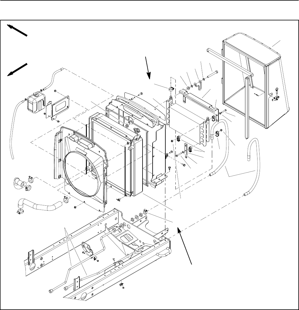
Reelmaster 5010- HHydraulic System Page 4 - 102
Hydraulic Oil Cooler
Figure 85
1. Oil cooler
2. Hose clamp (4 used)
3. Hydraulic hose (2 used)
4. Radiator
5. Cooler clamp (16 used)
6. Flat washer (8 used)
7. Cap screw (4 used)
8. Flange nut (10 used)
9. Top cooler bracket
10. Cap screw (2 used)
11. Washer (4 used)
12. Clamp (2 used)
13. Flange nut (4 used)
14. Cooler mount plate (2 used)
15. Cap screw (4 used)
16. Rear screen
17. Hydraulic tube (2 used)
FRONT
RIGHT
30 to 40 in- lb
(3.4 to 4.5 N- m)
3
17
11
2
1
13
14
15
11
16
7
9
2
13
10
6
12
4
5
5
5
8
8
6
30 to 40 in- lb
(3.4 to 4.5 N- m)

Reelmaster 5010- H Hydraulic SystemPage 4 - 103
Removal (Fig. 85)
1. Park machine on a level surface, lower cutting units,
stop engine, engage parking brake and remove key
from the ignition switch.
2. Unlatch and open the rear screen.
3. Remove battery to ease oil cooler removal (see 12
Volt Battery Service in the Service and Repairs section
of Chapter 5 - Electrical System).
4. Label all oil cooler hydraulic connections for as-
sembly purposes. Thoroughly clean hydraulic connec-
tions prior to loosening hydraulic hoses at oil cooler.
5. Loosen hose clamps that secure hydraulic hoses to
oil cooler fittings. Remove hoses from oil cooler. Allow
hoses to drain into a suitable container.
6. Rotate clamps that secure oil cooler to radiator
frame.
7. Carefully remove oil cooler from machine.
8. If necessary, remove clamps and brackets from oil
coolerusingFigure85asaguide.
Inspection
1. Back flush oil cooler with cleaning solvent. After cool-
er is clean, make sure all solvent is drained from the
cooler.
CAUTION
Use eye protection such as goggles when using
compressed air to clean the oil cooler.
2. Dry inside of oil cooler using compressed air in the
opposite direction of oil flow.
3. Plug both ends of oil cooler. Clean exterior of cooler.
Make sure oil cooler fins are clear of dirt and debris.
4. The oil cooler should be free of corrosion, cracked
tubes or excessive pitting of tubes.
Installation (Fig. 85)
1. If removed, install clamps and brackets to oil cooler
usingFigure85asaguide.
2. Position oil cooler to radiator and secure with
clamps.
3. Install hydraulic hoses to oil cooler fittings and se-
cure with hose clamps.
4. Install battery (see 12 Volt Battery Service in the Ser-
vice and Repairs section of Chapter 5 - Electrical Sys-
tem).
5. Close and secure rear screen.
6. Check oil level in hydraulic reservoir and add correct
oil if necessary.
Hydraulic
System
Reelmaster 5010- HHydraulic System Page 4 - 104
This page is intentionally blank.

Reelmaster 5010- H Page 5 - 1 Electrical System
Chapter 5
Electrical System
Table of Contents
GENERAL INFORMATION 2.....................
Operator’s Manual 2..........................
Electrical Drawings 2..........................
48 VDC Battery Disconnect 2..................
Toro Electronic Controller (TEC) 3..............
CAN- bus Communications 3...................
ELECTRICAL SYSTEM OPERATION 4............
12 VDC System Operation 4...................
48 VDC System Operation 5...................
SPECIAL TOOLS 6.............................
INFOCENTER DISPLAY 10......................
Splash Screen 10.............................
Main Information Screens 11...................
Access Protected Display Screens 12...........
Main Menu Screen 13.........................
Faults Screen 13.............................
Service Screen 14............................
Diagnostics Screen 15.........................
Settings Screen 16............................
About Screen 17..............................
TROUBLESHOOTING 18........................
Operator Advisories 18........................
Fault Codes 20...............................
Starting Problems 35..........................
General Run and Transport Problems 37.........
Cutting Unit Operating Problems 38.............
ELECTRICAL SYSTEM QUICK CHECKS 40.......
12 VDC Battery Test (Open Circuit Test) 40......
Engine Charging System Test 40...............
Glow Plug System Test 40.....................
Check Operation of Interlock Switches 41........
ADJUSTMENTS 42.............................
Traction Neutral Switch 42.....................
Parking Brake Switch 43.......................
Cutting Unit Down Limit Switch 44..............
Mow/Transport Switch 45......................
COMPONENT TESTING 46......................
Ignition Switch 46.............................
12 VDC System Fuses 47......................
48 VDC System Fuses 48......................
Engine Speed Switch 49.......................
Reel Engage/Disengage Switch 50..............
Headlight Switch 51...........................
Seat Switch 52...............................
Parking Brake Switch 53.......................
Traction Neutral Switch 54.....................
Cutting Unit Down Limit Switch 55..............
Joystick Raise and Lower Switches 56...........
Mow/Transport Switch 57......................
Main Power, Glow and 48 VDC Logic Relays 58..
Start Relay 60
................................
Main Contactor 61............................
Toro Electronic Controller (TEC) 62.............
Fusible Link Harness 64.......................
Diode Assembly 65...........................
48 VDC System Protection Diode 66............
Location ID Module 67.........................
Cutting Reel Motor 68.........................
CAN- bus Termination Resistors 69.............
Hydraulic Solenoid Valve Coil 70................
Temperature Sender 71........................
Oil Pressure Switch 72........................
Fuel Actuator 73..............................
Fuel Sender 74...............................
Fuel Pump 76................................
SERVICE AND REPAIRS 77.....................
Hydraulic Solenoid Valve Coils 77...............
12 VDC Battery Service 78.....................
48 VDC Battery Pack Service (Cutting Reel
and Motor/Generator Systems) 82.............
48 VDC Electrical Power Connections 86........
Cutting Reel Motor 88.........................
Cutting Reel Motor Service 90..................
Motor/Generator Assembly 92..................
Motor/Generator Assembly Service 96...........
Electrical
System
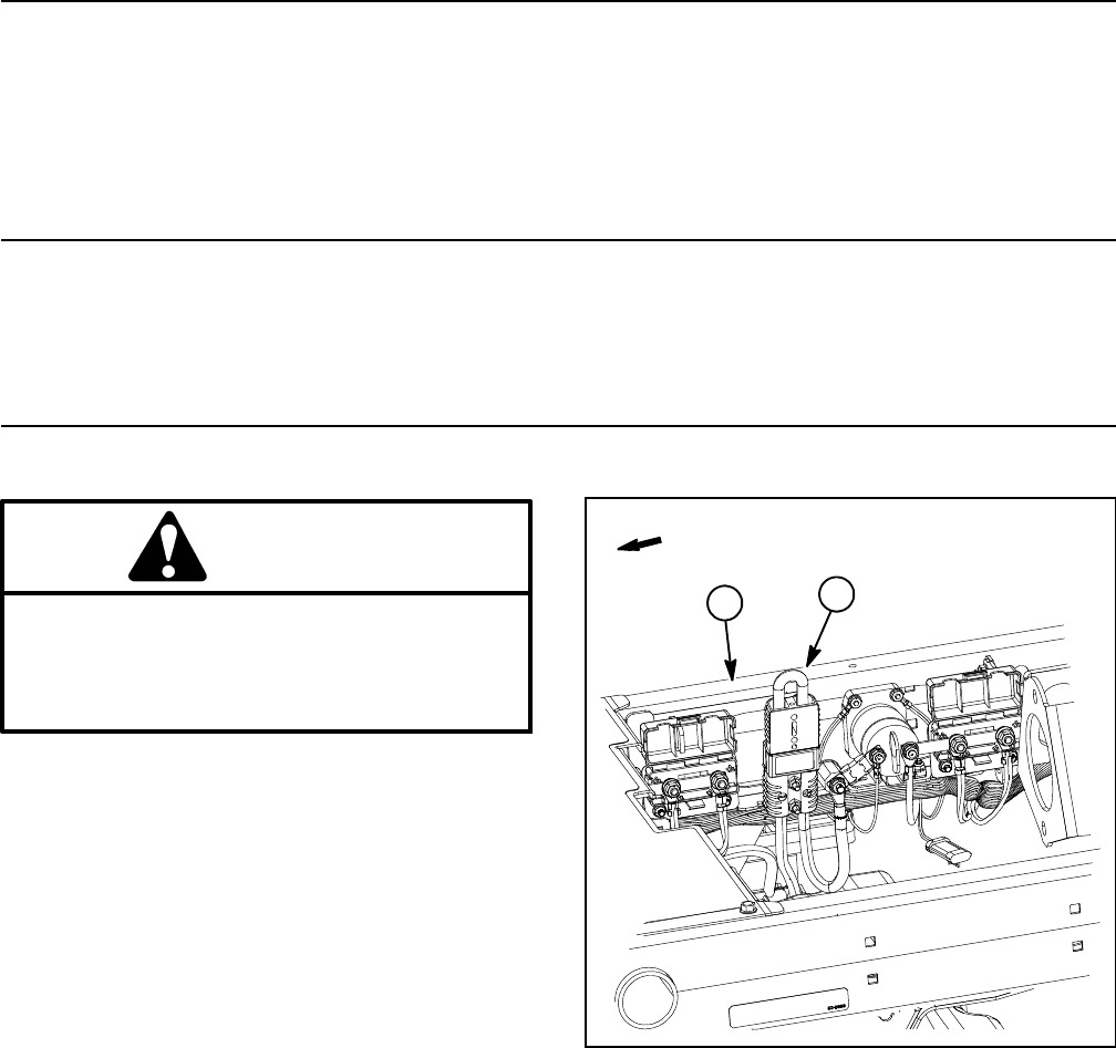
Reelmaster 5010- HPage 5 - 2Electrical System
General Information
Operator’s Manual
The Operator’s Manual provides information regarding
the operation, general maintenance and maintenance
intervals for your Reelmaster machine. Refer to that
publication for additional information when servicing the
machine.
Electrical Drawings
The electrical schematic and wire harness drawings for
Reelmaster 5010- H machines are located in Chapter 9
- Foldout Drawings.
48 VDC Battery Disconnect
CAUTION
Before installing, removing or servicing compo-
nents in the 48 VDC system (e.g. cutting unit mo-
tors, motor/generator), separate the 48 VDC bat-
tery disconnect. This will prevent unexpected
operation of 48 VDC system components.
The 48 VDC battery disconnect is attached to the right
frame rail under the operator seat (Fig. 1). Unplug the
disconnect to make sure that 48 VDC components do
not operate unexpectedly. Apply dielectric grease to the
contact surfaces of the battery disconnect and plug the
battery disconnect back in after service to the 48 VDC
system is completed.
1. RH frame rail 2. 48V battery disconnect
Figure 1
2
1
FRONT
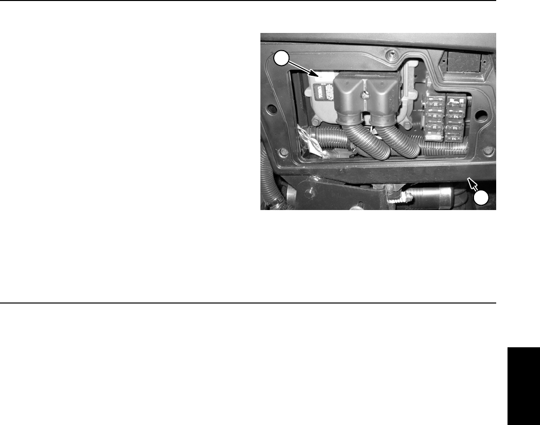
Reelmaster 5010- H Page 5 - 3 Electrical System
Toro Electronic Controller (TEC)
Reelmaster 5010- H machines use a Toro Electronic
Controller (TEC) to manage machine electrical func-
tions. The controller is microprocessor controlled that
senses the condition of various switches and sensors
(inputs). The controller then directs electrical power to
control appropriate machine functions (outputs) based
on the input state. Communication between the TEC
controller, the InfoCenter Display, the cutting unit motors
and the motor/generator is provided by a CAN- bus sys-
tem. The status of inputs to the TEC controller as well as
outputs from the TEC controller can be monitored with
the InfoCenter Display.
The TEC controller is located behind the access panel
on the outside of the control arm (Fig. 2).
IMPORTANT: To prevent machine electrical system
damage while welding on the machine, disconnect
the battery cables from the batteries, disconnect the
wire harness connectors from the Toro Electronic
Controller and disconnect the terminal connector
from the alternator.
1. Control arm 2. TEC controller
Figure 2
1
2
CAN- bus Communications
System communication between electrical components
on Reelmaster 5010- H machines is accomplished on
two (2) CAN- bus communication systems. These
CAN- bus systems reduce the number of electrical com-
ponents and connections used on the machine and al-
low the number of wires in the wire harness to be
reduced. The integration of machine electrical functions
also allows the InfoCenter Display to assist with electri-
cal system diagnostics.
One of these CAN- bus systems allows TEC controller
communication between machine 12 VDC components
(e.g. engine components, InfoCenter display). The sec-
ond CAN- bus system provides necessary control for
the electric cutting reels system (motor/generator, cut-
ting reel motors). An isolation module is included in the
machine electrical system to allow communication be-
tween the two systems while maintaining ground isola-
tion for the 48 VDC system.
CAN identifies the Controller Area Networks that is used
on the Reelmaster. Two (2) specially designed, twisted
wires form the bus for both of the networks used on the
Hybrid machines. These wires provide the data path-
ways between machine components. The engineering
term for these two (2) wires are CAN- high and CAN-
low. At the ends of the twisted pair of bus wires are 120
ohm termination resistors. The bus wires for the 12 VDC
circuitsareblack/whiteandred/whiteandthebuswires
for the 48 VDC circuits are green and yellow.
Each of the components that is controlled by the CAN-
bus link needs only four (4) wires to operate and commu-
nicate to the system: CAN High, CAN Low, B+ (power)
and ground. The CAN- bus needs the ignition switch ON
input for the TEC, InfoCenter Display, motor/generator
and cutting unit motors to be activated.
IMPORTANT: The termination resistors at the ends
of the bus wires are required for proper electrical
system operation.
Electrical
System

Reelmaster 5010- HPage 5 - 4Electrical System
Electrical System Operation
Reelmaster 5010- H machines use two (2) separate
electrical systems. Most machine functions operate on
a typical 12 VDC system. The second system exists to
operate the electric cutting reels and is a 48 VDC electri-
cal system. Basic information about the two systems is
included below.
12 VDC System Operation
Engine electrical components, machine operation
switches, hydraulic solenoid coils, the machine Toro
electronic controller (TEC) and the InfoCenter display
are all included in the 12 VDC system on Reelmaster
5010- H machines. A 12 volt battery at the rear of the
machine and the engine alternator provide system elec-
trical power. Circuit protection for the 12 VDC system in-
cludes two (2) fuse blocks, an inline TEC logic fuse and
several fusible links.
12 VDC system communication between the TEC con-
troller, InfoCenter display and the motor/generator is ac-
complished on a CAN- bus communication system. Two
(2) specially designed, twisted wires form the bus for this
network. The bus wires for the 12 VDC circuits are black/
white and red/white.
Information about electrical components in the 12 VDC
system is included in the Component Testing and Ser-
vice and Repairs sections of this chapter.

Reelmaster 5010- H Page 5 - 5 Electrical System
48 VDC System Operation
The Reelmaster 5010- H 48 VDC system includes a 48
VDC battery pack, an engine driven motor/generator as-
sembly, five (5) cutting reel motors, a main contactor
used to energize the system and additional circuit con-
trol components. Circuit protection for the 48 VDC sys-
tem includes five (5) fuses in a single fuse block, an
inline system logic fuse and a system Maxi- fuse.
The battery pack is composed of four (4) 12 VDC sealed
batteries connected in series to achieve the necessary
48 VDC system voltage. The batteries are absorbed
glass mat (AGM), valve regulated lead acid batteries
that are maintenance free.
IMPORTANT: When connecting the battery pack in
the 48 VDC system, make sure that battery polarity
is carefully checked. System damage can occur if
batteries are not connected correctly.
The motor/generator is a 48 VDC, air cooled, brushless,
permanent magnet device. The motor/generator has its
own integral invertor and on- board controller. The Info-
Center Display can be used to monitor motor/generator
activity during machine operation.
The five (5) cutting reel motors are identical 48 VDC,
brushless, permanent magnet motors. Each motor has
its own integral invertor and on- board controller. The In-
foCenter Display can be used to monitor the speed and
current draw for the five (5) cutting unit motors during
machine operation.
The main contactor exists in the 48 VDC system to con-
nect the 48 VDC battery pack with the motor/generator
and reel motor controllers. The motor/generator control-
ler determines when the main contactor is engaged.
Control for the components in the 48 VDC system is
handled by integral controllers in the motor/generator
and reel motors along with direction from the machine
TEC controller via the CAN- bus system. Since the TEC
controller (12 VDC component) sends and receives in-
formation with the motor/generator and reel motors (48
VDC components), the CAN- bus circuit needs to com-
municate with both systems. The isolation module is in-
cluded in the system to allow effective machine
communication while keeping the two electrical systems
isolated. Also, the location ID module exists to identify
the location of the five (5) cutting reel motors. This allows
such machine features as starting the rear cutting units
slightly later than the front cutting units.
The 48 VDC system is an isolated system so the vehicle
frame is not used for any ground connections in this sys-
tem. A 48 VDC battery disconnect is included on the ma-
chine which should be used to disconnect 48 VDC
system components from the electrical power supply to
prevent unexpected component operation when per-
forming service.
Information about electrical components in the 48 VDC
system is included in the Component Testing and Ser-
vice and Repairs sections of this chapter.
PowerMatchTM System
The PowerMatchTM system allows the Reelmaster
5010- H to control 48 VDC motor/generator operation so
that changing load conditions can be handled by the ma-
chine automatically.
In typical, lighter load conditions (e.g. mowing on flat
ground), engine output provides sufficient power to
drive the motor/generator and hydraulic pump package.
In this situation, the motor/generator keeps the 48 VDC
battery pack fully charged and the cutting reel motors
operational.
In moderate load conditions (e.g. mowing on intermedi-
ate slopes), the motor/generator transfers some or all of
its load from the engine. In these conditions, the cutting
reel motors can be driven exclusively by the battery pack
if needed. With the motor/generator load reduced or
possibly inactive, the engine maintains hydraulic trac-
tion performance while the battery pack assists in keep-
ing the reels running at the proper set speed.
If load conditions demand maximum performance (e.g.
mowing on severe inclines), the battery pack can be
used to power both the cutting unit motors and the mo-
tor/generator. The battery powered motor/generator as-
sists the engine in maintaining traction performance and
the battery pack keeps the reels running at the proper
set speed.
Electrical
System
Reelmaster 5010- HPage 5 - 6Electrical System
Special Tools
Order Special Tools from your Toro Distributor.
Digital Multimeter
The multimeter can test electrical components and cir-
cuits for current, resistance or voltage. Obtain this tool
locally.
NOTE: Toro recommends the use of a DIGITAL Volt-
Ohm- Amp multimeter when testing electrical circuits.
The high impedance (internal resistance) of a digital me-
ter in the voltage mode will make sure that excess cur-
rent is not allowed through the meter. This excess
current could cause damage to circuits not designed to
carry it.
Figure 3
Battery Terminal Protector
Toro Part Number: 107- 0392
Aerosol spray that should be used on battery terminals,
ring terminals and fork terminals to reduce corrosion
problems. Apply terminal protector to the connection af-
ter the battery cable, ring terminal or fork terminal has
been secured.
Figure 4
Dielectric Gel
Toro Part Number: 107- 0342
Dielectricgelshouldbeusedtopreventcorrosionofun-
sealed connection terminals. To ensure complete coat-
ing of terminals, liberally apply gel to both component
and wire harness connector, plug connector to compo-
nent, unplug connector, reapply gel to both surfaces and
reconnect harness connector to component. Connec-
tors should be thoroughly packed with gel for effective
results.
Do not use dielectric gel on sealed connection terminals
as the gel can unseat connector seals during assembly. Figure 5
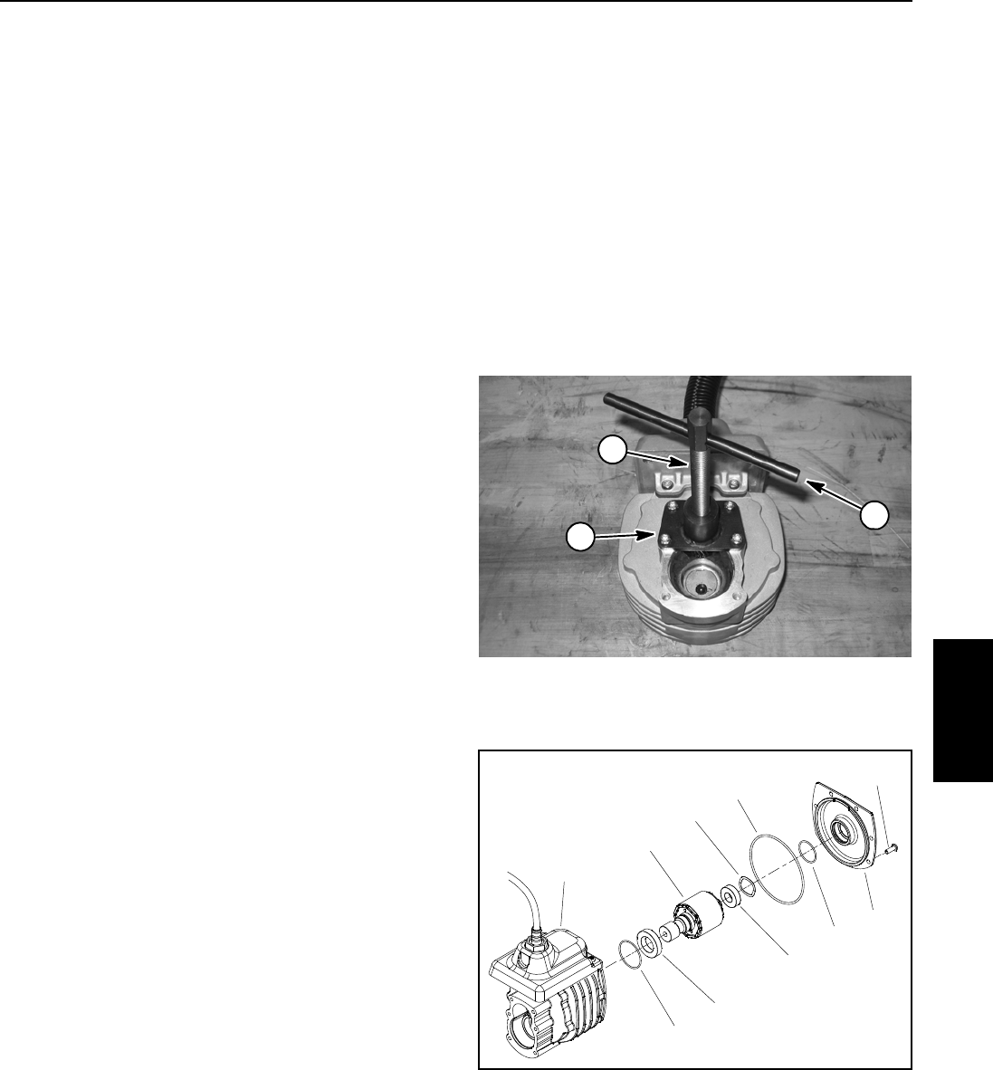
Reelmaster 5010- H Page 5 - 7 Electrical System
Cutting Reel Motor Rotor Tool Set
Toro Part Number: 127- 2574 (for both 5” and 7” cutting
unit motors)
The rotor tool set for the cutting reel motor is required to
remove and install the rotor from the reel motor housing.
Tool set includes puller hub, threaded shaft, handle and
four (4) screws (Fig. 6).
NOTE: Toro part number TOR6028 can be used to ser-
vice cutting unit motors on 5” cutting units and is also
used on other Toro products. TOR6028 will not work on
7” cutting unit motors.
NOTE: For cutting reel motor service procedures, see
Cutting Reel Motor Service in the Service and Repairs
section of this chapter.
IMPORTANT: When working on the cutting reel mo-
tor, use a clean work space with a non- metal sur-
face. The cutting reel rotor includes very powerful
magnets.
Cutting Reel Motor Rotor Removal
1. Remove gearbox cover and output gear from motor
assembly (see Cutting Reel Motor Service in the Ser-
vice and Repairs section of this chapter).
2. Remove screws that secure motor cover. Do not re-
move cover from motor assembly because it will be re-
moved with reel motor rotor during rotor removal.
3. Secure tool set base plate to motor housing with four
(4) of the cover screws.
4. Install threaded shaft into base plate.
IMPORTANT: The rotor magnets are very powerful
and can cause the rotor to shift position very rapidly
during removal. Be cautious during rotor removal to
prevent component damage or personal injury.
5. Turn threaded shaft with handle to remove rotor and
motor cover from motor housing. Support rotor to pre-
vent it from falling from housing during removal.
6. Leave threaded shaft installed in same position in
base plate for rotor installation purposes.
Cutting Reel Motor Rotor Installation
1. Secure tool set base plate to motor housing with four
(4) of the cover screws.
2. Make sure that threaded shaft is installed into base
plate so that the end of the threaded shaft prevents the
rotor body from entering the motor housing.
IMPORTANT: The rotor magnets are very powerful
and can cause the rotor to shift position very rapidly
during installation. Be cautious during rotor instal-
lation to prevent component damage or personal in-
jury.
3. While guiding rotor into motor housing, slowly rotate
threaded shaft to allow the rotor to be drawn into the
housing. Once rotor is fully installed into housing, re-
move tool set from motor housing.
Figure 6
1. Puller hub
2. Threaded shaft
3. Handle
1
2
3
1. Screw (6 used)
2. Motor cover
3. O- ring
4. O- ring
5. Wave washer
6. Bearing
7. Rotor
8. Bearing
9. O- ring
10. Housing assembly
Figure 7
7
5
6
8
3
9
2
41
10
Electrical
System
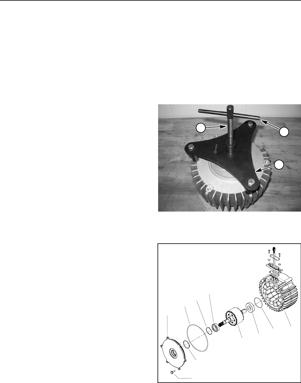
Reelmaster 5010- HPage 5 - 8Electrical System
Generator Rotor Tool Set
Toro Part Number: TOR6029
The generator rotor tool set is required to remove and
install the rotor from the motor/generator housing. Tool
set includes base plate, threaded shaft and handle (Fig.
8).
NOTE: For motor/generator service procedures, see
Motor/Generator Assembly Service in the Service and
Repairs section of this chapter.
IMPORTANT: When working on the motor/genera-
tor, use a clean work space with a non- metal sur-
face. The motor/generator rotor includes very
powerful magnets.
Motor/Generator Rotor Removal (Fig. 9)
1. Remove screws that secure motor/generator cover.
Do not remove cover from motor/generator assembly
because it will be removed with motor/generator rotor
during rotor removal.
2. Secure tool set base plate to motor/generator hous-
ing with three (3) 3/8” - 16 X 3” cap screws.
IMPORTANT: To prevent damage to motor/genera-
tor rotor shaft threads, position a thick washer or
spacer on end of the rotor shaft when using tool set.
3. Position thick washer or spacer on the end of the mo-
tor/generator rotor shaft. Install threaded shaft into base
plate and against washer or spacer on rotor shaft.
IMPORTANT: The rotor magnets are very powerful
and can cause the rotor to shift position very rapidly
during removal. Be cautious during rotor removal to
prevent component damage or personal injury.
4. Turn threaded shaft with handle to remove motor/
generator rotor and cover from motor/generator hous-
ing. Support rotor to prevent it from falling during
removal.
5. Leave threaded shaft installed in same position in
tool base plate for rotor installation purposes.
Motor/Generator Rotor Installation (Fig. 9)
1. Secure tool set base plate to motor/generator hous-
ing with three (3) 3/8” - 16 X 3” cap screws.
2. Make sure that threaded shaft is installed into tool
base plate so that the end of the threaded shaft prevents
rotor body from entering the motor/generator housing.
IMPORTANT: The rotor magnets are very powerful
and can cause the rotor to shift position very rapidly
during installation. Be cautious during rotor instal-
lation to prevent component damage or personal in-
jury.
3. While guiding rotor into motor/generator housing,
slowly rotate threaded shaft to allow the rotor to be
drawn into the housing. Once rotor is fully installed into
housing, remove special tool set from motor/generator
housing.
1. Base plate
2. Threaded shaft
3. Handle
Figure 8
1
23
1. Housing/stator assembly
2. O- ring
3. Bearing
4. Rotor assembly
5. Bearing
6. Wave washer
7. O- ring
8. O- ring
9. Cover
10. Flange screw (6 used)
Figure 9
2
3
6
8
9
10
1
5
7
4
Reelmaster 5010- H Page 5 - 9 Electrical System
Battery Hydrometer
Use the battery hydrometer when measuring specific
gravity of battery electrolyte in the machine 12 VDC bat-
tery. Obtain this tool locally.
NOTE: A battery hydrometer is not usable for the bat-
teries in the Reelmaster 5010- H 48 VDC battery sys-
tem. These batteries are valve regulated, sealed lead
acid batteries that are maintenance free with no provi-
sion for checking or adjusting electrolyte level. Figure 10
Plastic Plug
Toro Part Number: 2410- 30 (for 5 inch reels)
94- 2703 (for 7 inch reels)
This cap is used for placement into the cutting unit side
plate when the cutting reel motor is removed. It prevents
dirt and debris from entering the cutting reel bearing
area.
Figure 11
Electrical
System
Reelmaster 5010- HPage 5 - 10Electrical System
InfoCenter Display
The InfoCenter Display used on your Reelmaster is a
LCD device that is located on the console. The InfoCent-
er provides information for the machine operator during
machine operation, provides electrical system diagnos-
tic assistance for technicians and allows inputs for ad-
justable machine settings.
Power for the InfoCenter is available when energized by
the main power relay (ignition switch in the ON/PRE-
HEAT or START position). CAN- bus systems involving
the machine TEC controller, the InfoCenter, the motor/
generator and the cutting unit motors are used to pro-
vide necessary machine communication for InfoCenter
operation.
NOTE: Icons that are used on the InfoCenter display
are identified in the Traction Unit Operator’s Manual.
Splash Screen
The InfoCenter splash screen (Fig. 12) is displayed
when the ignition switch is initially turned to the ON/
PREHEAT or START position. The splash screens allow
basic machine information to be reviewed by the operat-
or. After the splash screens has been on the InfoCenter
for several seconds, the main information screen will be
displayed on the InfoCenter.
The splash screen can be used to identify machine 12
VDC battery voltage, hourmeter reading, fuel tank level
and whether the glow plugs are energized.
1. 12 VDC battery voltage
2. Hour meter
3. Fuel gauge
4. Glow plugs energized
5. Right button
6. Middle button
7. Menu/back button
Figure 12
12.6V
2
95.2
T
4
1
765
3

Reelmaster 5010- H Page 5 - 11 Electrical System
Main Information Screens
The two (2) InfoCenter main information screens (Figs.
13 and 14) are displayed after the initial splash screen
has been displayed for several seconds. During normal
machine operation, the main information screens
provide machine information for the operator. Toggling
between the main information screens is done by press-
ing the right button on the InfoCenter.
The main information screens can be used to monitor
engine coolant temperature, fuel tank level, 48 VDC bat-
tery voltage, engine RPM, motor/generator temperature
and traction speed range. The screens will also identify
if the parking brake is applied or if the cutting decks are
engaged.
The main information screens will also display arrows
whenever the cutting deck sections are either raising
(up arrows) or lowering (down arrows).
If controls are not selected properly to allow certain ma-
chine operations, the InfoCenter indicator light will illu-
minate and an advisory will be displayed on the
InfoCenter Display (see Advisories in the Troubleshoot-
ing section of this chapter). Typically, an advisory can be
eliminated with a change in controls by the operator.
If an electrical machine fault occurs during machine op-
eration, the InfoCenter indicator light will blink to notify
the operator. Accessing the fault log is described below
in Faults Screen.
The main menu and additional information screens can
be accessed from the InfoCenter main information
screen by pressing and releasing the menu/back button
(left button) on the display. Information on the main
menu and menu item screens is included below.
1. Parking brake applied
2. Traction speed range
3. Coolant temperature
4. Indicator light
5. Fuel gauge
6. Right button
7. Middle button
8. Menu/back button
Figure 13
100
170 240
P
4
N
5
876
3
2
1
1. Engine RPM
2. Coolant temperature
3. Indicator light
4. Generator temperature
5. 48 VDC battery voltage
6. Right button
7. Middle button
8. Menu/back button
Figure 14
3
4
52.3V
1400 RPM
120
190 260
100
170 240
876
5
2
1
Electrical
System
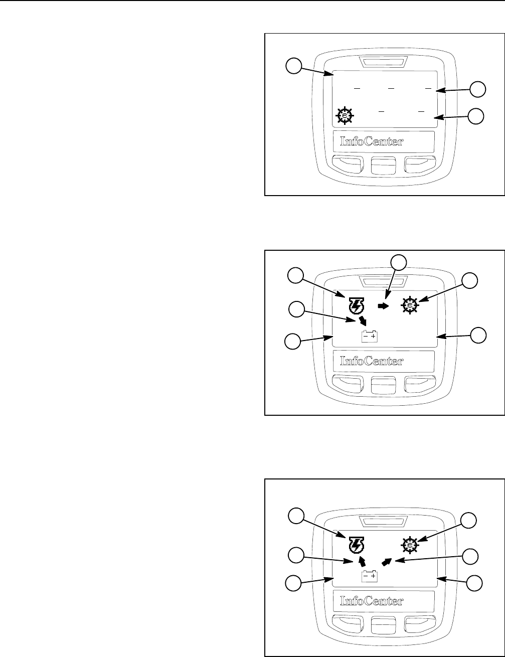
Reelmaster 5010- HPage 5 - 12Electrical System
Access Protected Display Screens
The protected display screens are available on the Info-
Center to view the electrical status of the 48 VDC power
circuit. The protected display screens can be viewed af-
ter the Protected Menus are available by entering the
machine PIN (see Settings Screen in this section). Tog-
gling between the protected display screens is done by
pressing the middle button on the InfoCenter when they
are active.
The eReel Info screen (Fig. 15) displays the speed and
current draw for the five (5) individual cutting unit mo-
tors.
In typical, lighter load conditions (e.g. mowing on flat
ground), engine output provides sufficient power to
drive the motor/generator and hydraulic pump package.
In this situation, the motor/generator keeps the 48 VDC
battery pack fully charged and the cutting reel motors
operational (Fig. 16).
In moderate load conditions (e.g. mowing on intermedi-
ate slopes), the 48 VDC battery system can be used to
power the cutting reel motors and the motor/generator
load is reduced or removed from the engine. With the
motor/generator inactive, the engine maintains traction
performance while the batteries keep the reels running
at the set speed.
If load conditions demand maximum machine perfor-
mance (e.g. mowing on severe inclines), the battery
pack can be used to power both the cutting unit motors
and the motor/generator (Fig. 17). The battery powered
motor/generator assists the engine in maintaining trac-
tion performance and the battery pack keeps the reels
running at the proper set speed.
1. Reel information screen
2. Front motors
3. Rear motors
Figure 15
eReel Info
13A
1600 n
min
13A
1600 n
min
13A
1600 n
min
13A
1600 n
min
13A
1600 n
min
1
3
2
1. 48V battery pack status
2. Motor/generator
3. Reel motor circuit
4. Engine RPM
5. Energy flow
Figure 16
5A
55.0 V 3000 RPM
1
2
4
3
5
5
Figure 17
-80A
46.0 2850 RPM
1
2
4
3
1. 48V battery pack status
2. Motor/generator
3. Reel motor circuit
4. Engine RPM
5. Energy flow
5
5
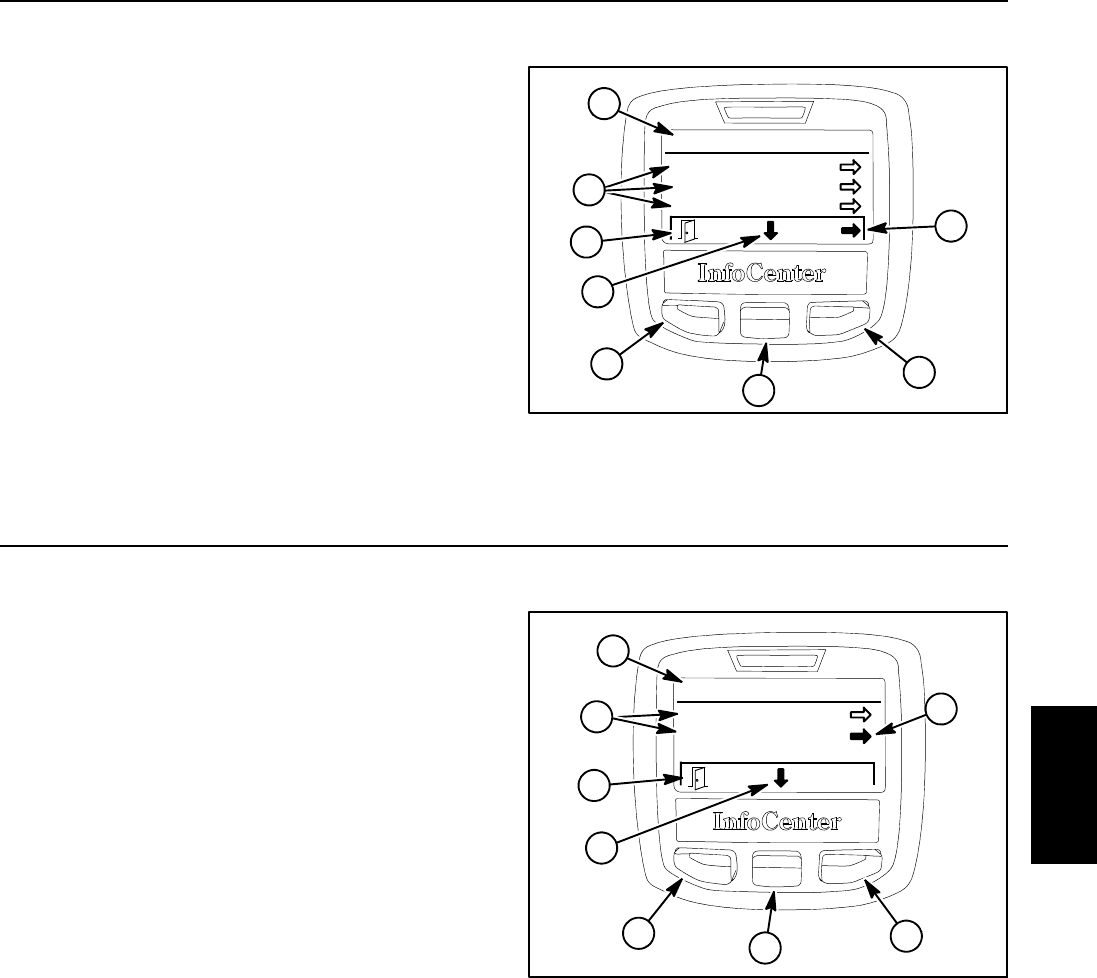
Reelmaster 5010- H Page 5 - 13 Electrical System
Main Menu Screen
The main menu screen can be accessed from the Info-
Center main information by pressing and releasing the
menu/back button (left button) on the display twice.
Once at the main menu screen (Fig. 18), navigation to
the five (5) different menu items can occur. Pressing the
move to menu item button (middle button) allows a dif-
ferent menu item to be highlighted. Selection of the high-
lighted item is completed by pressing the choose menu
item button (right button).
The main menu items include faults, service, diagnos-
tics, settings and about. These menu items are de-
scribed below.
To return to the main information screen from the main
menu screen, press the back button (left button).
1. Main menu
2. Menu items
3. Move to menu items
4. Choose menu item
5. Back button
Figure 18
Main Menu
Faults
Service
Diagnostics
2
4
4
3
5
3
5
1
Faults Screen
The faults screen (Fig. 19) will list all machine electrical
faults that have occurred since the faults were last
cleared from the InfoCenter. The faults will be identified
by a fault number and when the fault occurred. Faults
that might occur on the machine are listed in Fault
Codes in the Troubleshooting section of this chapter.
After entry of the PIN code (see Protected Menus in the
Settings Screen of this section), the InfoCenter fault log
can be cleared by selecting the clear system faults menu
item in the faults screen. The cleared faults will be re-
moved from the InfoCenter list but will be retained in the
TEC controller memory.
If a fault occurs during machine use, there may be a
change in machine functionality due to the fault. Should
there be machine operation issues due to a fault, a first
step to remedy the issue would be to disengage the cut-
ting units, release the traction pedal, wait for the ma-
chinetostopmoving,turnthe ignition switch OFF and
allow all machine functions to stop. Then, attempt to re-
start the machine to see if operation has returned to nor-
mal. Some faults will be reset during the restart and will
then allow normal function. If a fault continues to occur,
further system evaluation and possible component re-
pair or replacement will be necessary.
To return to the main menu screen from the faults
screen, press the back button (left button).
1. Fault menu
2. Fault items
3. Move to menu items
4. Choose menu item
5. Back button
Figure 19
Faults
Cleared @ -27.6Ago
5
#39 -13.3Ago
1
2
3
534
4
Electrical
System
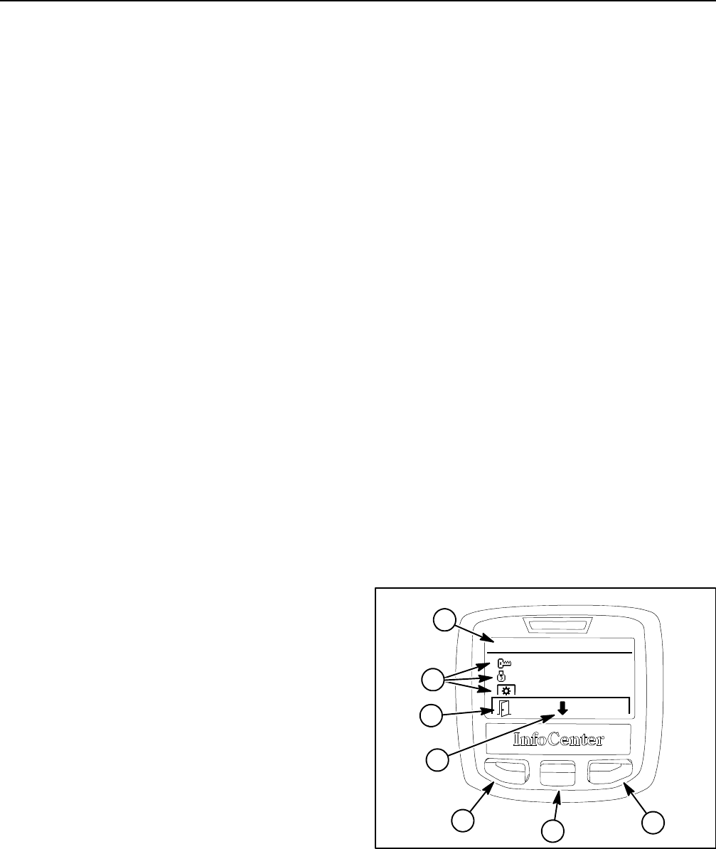
Reelmaster 5010- HPage 5 - 14Electrical System
Service Screen
The service screen (Fig. 20) contains machine opera-
tional information including hours, counts, reset defaults
and cutting unit backlap engage. Values listed for these
service menu items cannot be changed. If the machine
PIN has been entered to allow access to protected menu
items in the settings screen, the protected service menu
items will be listed and available in the service screen.
NOTE: If the protected menu items are available, PIN
will be shown in the upper right corner of the InfoCenter
display.
The options listed for hours include the following:
DKey On identifies the number of hours that the igni-
tion switch has been in the ON/PREHEAT position.
DMachine Run identifies the number of hours that the
engine has been running.
DPTO On identifies the number of hours that the ma-
chine has been operated with the cutting units engaged.
DFront Cutting Units in Backlap identifies the num-
ber of hours that the front cutting units have been oper-
ated in the backlap position.
DRear Cutting Units in Backlap identifies the num-
ber of hours that the rear cutting units have been oper-
ated in the backlap position.
DTransport Speed identifies the number of hours that
the machine has been operated in transport speed.
DService Due identifies the number of hours before
the next scheduled maintenance is due. The service
due hours listed on the InfoCenter will decrease as the
machine is used. The service due hours can be reset af-
ter maintenance is performed.
The options listed for counts include the following:
DStarts identifies the number of times that the engine
has been started.
DPTO identifies the number of times that the engage/
disengage switch has been engaged.
DFront Cutting Units in Backlap identifies the num-
ber of times that the front cutting units have been oper-
ated in the backlap position.
DRear Cutting Units in Backlap identifies the num-
ber of times that the rear cutting units have been oper-
ated in the backlap position.
DEngine Coolant Caution identifies the number of
times that engine coolant temperature was elevated.
DEngine Coolant Excessive identifies the number of
times that excessive engine coolant temperature
caused the engine to stop.
DBattery kW- H identifies the total electrical energy
(in kilowatt hours) that has been provided by the 48 VDC
battery pack. The battery kW- H listed on the InfoCenter
will increase as the machine is used. The battery kW- H
can be reset when needed (e.g. battery pack is re-
placed).
The reset defaults service screen option allows ma-
chine settings to be returned to factory defaults.
The front cutting units backlap service screen option
allowsthefrontcuttingunitstobeplacedinbacklap.
The rear cutting units backlap service screen option
allows the rear cutting units to be placed in backlap.
IMPORTANT: If the backlap function is not returned
to the OFF setting after backlapping, the cutting
units will not raise or function properly.
To reset the service due hours or battery kW- H count,
access the protected menu so that PIN is shown on Info-
Center display. The protected menu items for resetting
the service due hours and battery kW- H count will be
available on the InfoCenter.
To return to the main menu screen from the service
screen, press the back button (left button).
1. Service menu
2. Service items
3. Move to menu items
4. Choose menu item
5. Back button
Figure 20
Hours
:
Run:
:
38.9 Hours
36.8 Hours
13.9 Hours
534
5
2
3
1
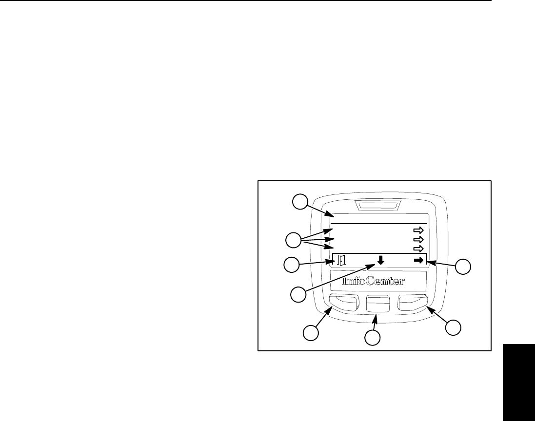
Reelmaster 5010- H Page 5 - 15 Electrical System
Diagnostics Screen
The diagnostics screen (Fig. 21) lists the various states
of machine electrical components. The diagnostics
screen should be used to check operation of machine
controls and to verify that switches and circuit wiring are
functioning correctly.
For each of the diagnostics screen items, inputs, qualifi-
ers and outputs are identified. The diagnostics screen
includes the following:
DCutting Units identifies machine requirements to al-
low the cutting units to raise and lower. Inputs indicate
the state of the joystick raise and lower switches and the
position of the ignition switch. Qualifiers include whether
the engine is running and the seat is occupied, that the
traction system is in the LOW range speed and inputs
are OK to lower and raise. Identified outputs consist of
SV1, SV2, SV3 and SVRV solenoid coils.
DHi/Low Range identifies machine requirements to
allow LOW (mow) or HI (transport) speed range to be
engaged. Inputs indicate the state of the mow/transport
switch. Qualifiers identify the position of the seat switch,
whether the cutting units are raised and the position of
the engage/disengage (PTO) switch. There are no out-
puts from the TEC controller for the Hi/Low range func-
tion.
DPTO identifies machine requirements to allow the
cutting units to be engaged. Inputs indicate the state of
the PTO (engage/disengage) switch. Qualifiers identify
whether LOW speed range is selected, if the engine is
running, if the seat is occupied, if the engine tempera-
ture is not excessive and if the cutting units are lowered.
Outputs indicate that the rear cutting units and/or the
front cutting units are engaged.
DEngine Start identifies whether necessary TEC out-
puts exists to allow the engine to start and run. Inputs in-
dicate the state of the ignition switch (ON and START).
Qualifiers identify whether the joystick is in the neutral
position (neither lower nor raise engaged), that the PTO
(engage/disengage) switch is OFF, if the traction pedal
is in neutral and if the seat is occupied or parking brake
is applied. Outputs indicate that the fuel actuator is ener-
gized and, when the ignition switch is in the START posi-
tion, that the start output is energized.
DBacklap identifies machine requirements to allow
the cutting unit backlap process to be engaged. Inputs
indicate the state of the backlap settings (ON or OFF
from Service menu screen) and the PTO status (ON or
OFF). Qualifiers identify that the parking brake is ap-
plied, the mow/transport lever is in the MOW position,
the cutting units are lowered and that the engine is run-
ning. Outputs indicate whether the front and/or the rear
cutting units are in the backlap mode.
To return to the main menu screen from the diagnostics
screen, press the back button (left button).
1. Diagnostics menu
2. Diagnostics items
3. Move to menu items
4. Choose menu item
5. Back button
Figure 21
Diagnostics
Cutting Units
Hi/Low Range
PTO
53
4
5
2
3
4
1
Electrical
System
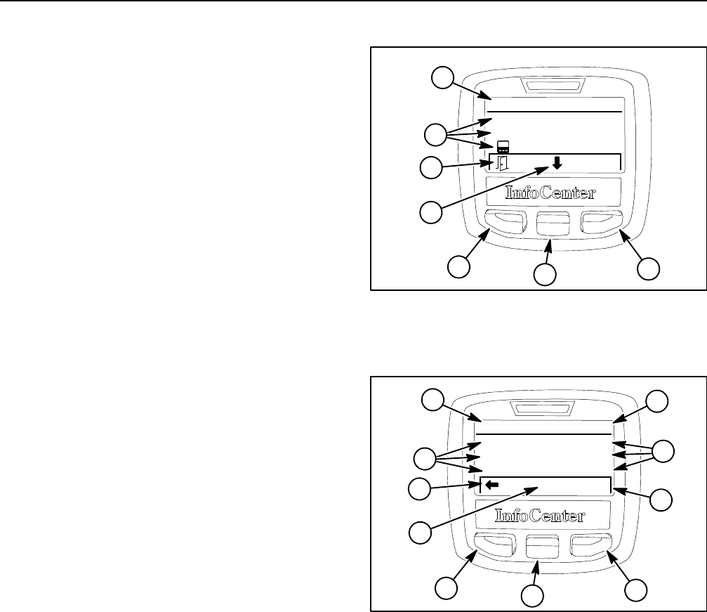
Reelmaster 5010- HPage 5 - 16Electrical System
Settings Screen
The settings screen identifies the InfoCenter units (En-
glish or Metric) and language. The settings screen also
allows the operator to customize the backlight (bright-
ness) and contrast settings for the InfoCenter display.
If either the backlight (brightness) or contrast items are
selected, the middle button (- ) or right button (+) can be
used to change the display settings.
The settings screen includes the current setting for
backlapping speed (B’lap RPM) for the front (F) and
rear (R) cutting units. Backlapping speed can be adjust-
ed by selecting either the front or rear cutting units and
using the right button on the InfoCenter to modify the
speed.
Protected menus allows the machine PIN to be en-
tered so that hidden machine settings screen items can
be viewed and modified. Protected menu items include
protect settings, auto idle, blade count, mow speed,
height of cut (HOC), front reel RPM, rear reel RPM and
economy mode.
To allow access to the protected menu items when pro-
tected settings is ON (see Protected settings below),
enter the four (4) digit pin PIN using the middle and right
InfoCenter buttons. After PIN has been entered, a check
mark should be visible above middle InfoCenter button.
Press middle button and the InfoCenter display screen
should indicate “PIN” in the upper right hand corner if the
correct PIN number was entered. The protected menu
items should be available in the settings menu and can
be changed as long as the ignition switch remains in
RUN and “PIN” is displayed on the InfoCenter.
NOTE: The initial PIN will either be 1234 or 0000. If the
PIN has been changed and is forgotten, a temporary
PIN can be obtained from your Toro distributor.
To change the machine PIN, access the protected menu
items by entering the current PIN. The InfoCenter dis-
play screen should indicate “PIN” in the upper right hand
corner after the current PIN number is entered. Select
the protected menu item again and note that “Edit PIN”
is indicated on InfoCenter display screen. A new PIN
can be entered and then saved.
Protected settings allows the settings for auto idle,
blade count, mow speed, height of cut (HOC), front reel
RPM, rear reel RPM and economy mode to be hidden
so they cannot be changed unless the PIN is entered. If
the protect settings is ON, these settings will not be seen
when using the InfoCenter until the protected menus is
selected and the machine PIN is entered. If protect set-
tings is OFF (default setting), settings for these func-
tions will be visible on the InfoCenter and can be
adjusted by the operator at any time.
1. Settings menu
2. Settings items
3. Move to menu items
4. Change menu item
5. Back button
Figure 22
Settings
Units:
Language:
Backlight:
English
English
40%
+/-
3
534
5
2
1
Figure 23
1. Settings menu
2. Settings items
3. Current settings
4. Increase setting
5. Decrease setting
6. Back button
7. PIN activated
Settings
Auto Idle:
Blade Count:
Mow Speed:
-
5
1
4
645
6
2
+
20s
5
6.0 mph
PIN
7
3
Auto Idle causes the engine speed to decrease to low
idle after the machine has not been in use for the set time
delay in seconds. Auto idle can be adjusted to 8, 10, 15,
20 or 30 seconds or the auto idle feature can be turned
OFF. Engine speed automatically returns to the previ-
ously set speed when either the traction pedal is moved
from neutral or the joystick is moved to either raise or
lower.
Blade Count identifies the number of blades on the cut-
ting units installed on the machine. This information is
used by machine controllers to determine cutting unit
reel speed.
Mow Speed identifiesthetractionspeedtobeused
when in LOW (mow) speed. This information is used by
machine controllers to determine cutting unit reel speed.
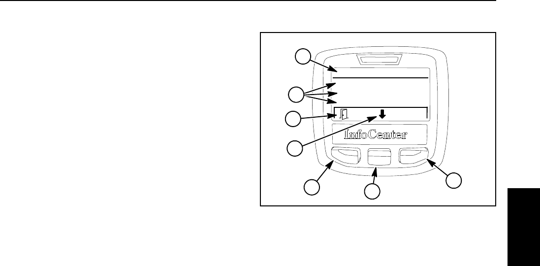
Reelmaster 5010- H Page 5 - 17 Electrical System
Height of Cut (HOC) identifies the setting for cutting
unit height of cut. This information is used by machine
controllers to determine cutting unit reel speed.
FReelRPMdisplays the front reel speed that has been
determined by the machine controllers based on en-
tered information for blade count, mow speed and HOC.
Front reel speed can also be manually adjusted.
RReelRPMdisplays the rear reel speed that has been
determined by the machine controllers based on en-
tered information for blade count, mow speed and HOC.
Rear reel speed can also be manually adjusted.
Economy Mode displays whether the machine has the
economy mode feature ON or OFF. When in economy
mode with the mow/transport lever in the MOW position,
the engine speed is lowered to reduce noise and fuel
consumption. When in economy mode with the mow/
transport lever in the TRANSPORT position, engine
speed is not lowered.
To return to the main menu screen from the settings
screen, press the back button (left button).
About Screen
The about screen (Fig. 24) identifies the machine model
number, machine serial number and software revisions
for the TEC controller. If the machine PIN has been en-
teredtoallowprotectedmenu items to be visible, the
about screen will also identify software revisions for the
cutting unit and motor/generator controller and list the
CAN- bus status.
To return to the main menu screen from the about
screen, press the back button (left button).
Figure 24
About
Model:
SN:
S/W Rev:
03674
315000153
122- 0059B
1
53
4
5
2
1. About menu
2. About items
3. Move to menu items
4. Choose menu item
5. Back button
3
Electrical
System
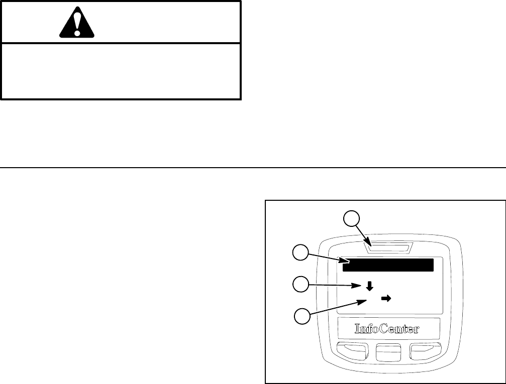
Reelmaster 5010- HPage 5 - 18Electrical System
Troubleshooting
CAUTION
Remove all jewelry, especially rings and
watches, before doing any electrical trouble-
shooting or testing. Disconnect the battery
cables unless the test requires battery voltage.
For effective troubleshooting and repairs, there must be
a good understanding of the electrical circuits and com-
ponents used on this machine (see Chapter 9 - Foldout
Drawings).
If the machine has any interlock switches by- passed,
they must be reconnected for proper troubleshooting
and safety.
NOTE: Use the InfoCenter Display to test TEC con-
troller inputs and outputs when troubleshooting an elec-
trical problem on your Reelmaster (see InfoCenter
Display in this chapter).
Operator Advisories
If controls are not selected properly to allow certain ma-
chine operations, the InfoCenter indicator light will illu-
minate and an advisory will be displayed on the
InfoCenter Display. Typically, an advisory can be elimin-
ated with a change in controls by the operator.
Advisory numbers, descriptions and reason for advi-
sories are listed in the table on the next page. Some ad-
visories can be caused by several machine settings.
NOTE: Icons that are used on the InfoCenter display
are identified in the Traction Unit Operator’s Manual.
1. Indicator light
2. Advisory number
3. Advisory description
4. Reason for advisory
Figure 25
3Denied
LH
1
ADVISORY #162
2
4

Reelmaster 5010- H Page 5 - 19 Electrical System
Advisory
Number
Advisory Description Possible Reason for Advisory
160 Start Denied Neither seat occupied nor parking brake
applied
Traction pedal is NOT in neutral position
Wait to start until system functions have been
initialized
Joystick is in RAISE position
Joystick is in LOWER position
Reel engage/disengage switch is in engaged
position
161 Mow Denied No operator in seat
Engine coolant temperature is excessive
Low voltage in 48 VDC battery pack
162 Lowered Denied Mow stop lever is in TRANSPORT position
163 Backlap Denied Traction pedal is not in neutral position
Mow stop lever is in TRANSPORT position
Engine coolant temperature is excessive
Parking brake is NOT applied
Reel engage/disengage switch is NOT in
engaged position
Cutting units are NOT fully lowered
169 Engine Shutdown No operator in seat
Parking brake IS applied
Engine coolant temperature is excessive
Engine oil pressure is low
170 Recycle Keyswitch (ignition switch) Engine starter motor has been engaged for 30
seconds
173 Master Address Claim
175 Check Reel Speed Settings Check that reel speed settings are correct for
cutting units on machine
176 Reel Speed Changed Identifies that reel speed has been changed
177 Reel Speed Changed Out Of Range
178 Low 48 VDC Battery Heavy 48 VDC battery pack use has
decreased battery pack charge
Electrical
System
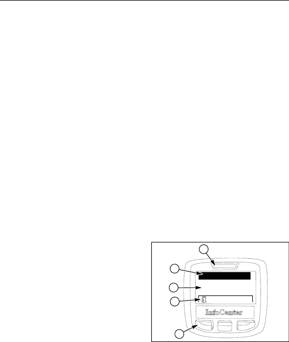
Reelmaster 5010- HPage 5 - 20Electrical System
Fault Codes
The InfoCenter Display will identify electrical system
malfunctions (faults) if they occur. Should a fault occur
during machine operation, the InfoCenter indicator light
will illuminate and the fault will be displayed on the Info-
Center Display (Fig. 26).
The InfoCenter display faults screen will list all machine
electrical faults that have occurred since the faults were
last cleared from the InfoCenter. The faults will be identi-
fied by a fault number and when the fault occurred.
Fault codes, fault descriptions and recommended ser-
vice suggestions for fault codes are listed in the table on
the following pages.
NOTE: Icons that are used on the InfoCenter display
are identified in the Traction Unit Operator’s Manual.
NOTE: Fault codes identify electrical problems that typ-
ically will prevent normal machine operation. For fault
codes that identify problems with TEC controller inputs
(e.g. switches, sensors), use the InfoCenter Display to
check the different switch positions before removing or
replacing the component. Fault codes that identify prob-
lems with TEC controller outputs (e.g. solenoid coils)
might involve issues with the wire harness or the actual
output device.
Using Fault Codes
If an electrical fault is identified by the machine con-
trollers (TEC, motor/generator, cutting unit motors), the
InfoCenter display will identify the fault code number
and when the fault occurred. An electrical fault can
cause disruption in how the machine functions but in
some instances, the fault may occur with little, if any,
change in machine operation. The following sugges-
tions should be considered when using fault codes that
are displayed.
SIf a fault code is displayed on the InfoCenter and ma-
chine operation remains normal, continue to use the
machine. The fault code number can be retrieved in the
future by using the InfoCenter faults screen.
SIf a fault code is displayed on the InfoCenter and ma-
chine operation has changed, move the machine to a
level surface, disengage the cutting units and turn the ig-
nition switch to the OFF position. Leave switch in the
OFF position for thirty (30) seconds and then restart the
machine. During this system reboot process, the ma-
chine controllers often can reset electrical components
to allow normal machine operation. Assuming that the
fault code is no longer displayed, continue to use the
machine. The fault code number can be retrieved in the
future by using the InfoCenter faults screen.
SThere is the possibility that an electrical issue can re-
sult with several fault codes being generated. For exam-
ple, a broken wire or faulty fuse would prevent operation
of a cutting unit motor and multiple fault codes could be
displayed. Reviewing the fault code descriptions should
suggest possible causes for the circuit problem. Using
the electrical schematic and electrical wire harness
drawings will also help in problem diagnosis.
SThe InfoCenter will display fault code numbers as an
indication that the machine electrical system has experi-
enced an abnormal change that might be very minor re-
sulting in no change of machine operation or more
severe which could prevent machine use. Use fault
codes in conjunction with noting what machine opera-
tions have changed, when did the change occur and
whether the problem occurs all the time or is intermittent
to help identify the source of a machine problem.
SThe InfoCenter faults screen can be used to list all ma-
chine electrical faults that have occurred since the faults
were last cleared from the InfoCenter. If a fault that is list-
ed on the InfoCenter faults screen occurred at some
point in the distant past and has not reoccurred, that fault
is likely not causing a current machine problem. Recur-
ring faults may indicate a problem with a particular circuit
or component.
SWhen machine electrical issues occur and fault codes
have been displayed on the InfoCenter display, consider
contacting your Toro Distributor for additional assis-
tance.
1. Indicator light
2. Fault number
3. Fault description
4. Back button
Figure 26
348V Devices Offline
1
FAULT #28
2
4
4

Reelmaster 5010- H Page 5 - 21 Electrical System
Fault Code Fault Description Service Suggestions
1Excessive engine coolant temperature (above
105oC) caused PTO to disengage
Check radiator and screen for debris buildup
Check engine cooling fan and drive belt
Check engine coolant level
2Excessive engine coolant temperature (above
115oC) caused engine to stop
Check radiator and screen for debris buildup
Check engine cooling fan and drive belt
Check engine coolant level
3One of the TEC output fuses (7.5 Amp) is
faulty
Check TEC output fuses
4 IPE voltage is low indicating that TEC fuses or
TEC controller is faulty
Check TEC fuses
Consider that TEC controller is faulty
5Main power relay is faulty Check main power relay and circuit wiring
6Ignition switch was held in the START position
for more than thirty (30) seconds or the ignition
switch is faulty
Cycle ignition switch
Check fuel level in fuel tank
Check ignition switch and circuit wiring
Check fuel actuator and fuel pump
7TEC software needs to be reprogrammed Contact Toro Distributor for reprogramming
assistance
8Engine alternator charging is too high Check engine alternator
9Engine alternator charging is too low Check alternator drive belt
Check engine alternator and circuit wiring
13 Ignition switch is faulty Check ignition switch and circuit wiring
15 Engine speed switch is faulty Check control arm engine speed switch and
circuit wiring
16 Engine alternator is faulty Check engine alternator and circuit wiring
17 48 VDC logic relay current is excessive Check 48V logic relay and circuit wiring
19 Engine coolant temperature sensor circuit has
open or short
Check engine coolant sensor and circuit wiring
21 ID Module is faulty Unplug cutting unit motors one at a time to find
a possible faulty cutting unit motor
Check ID module and circuit wiring
24 Joystick raise and lower switches closed at
same time
Check joystick switches and circuit wiring
26 TEC output current to energize start relay is
excessive
Check start relay and circuit wiring
27 TEC output current to fuel pump is excessive Check fuel pump and circuit wiring
Electrical
System

Reelmaster 5010- HPage 5 - 22Electrical System
Fault Code Fault Description Service Suggestions
28 48 VDC devices (motor/generator and all cut-
ting reel motors) are all off- line
Make sure that 48 VDC battery disconnect is
securely plugged in
Check 10A logic relay fuse
Check 48 VDC master fuse (250A maxi fuse)
Check 48 VDC battery system voltage
Check 48 VDC logic relay and circuit wiring
Check isolation module and circuit wiring
Check CAN- bus termination resistors and cir-
cuit wiring
29 48 VDC system (motor/generator and all cut-
ting reel motors) is under voltage
Check 48 VDC battery voltage
Check 48 VDC battery connections
Check internal motor/generator connections
Consider that motor/generator is faulty
30 48 VDC system (motor/generator and all cut-
ting reel motors) is over voltage
Check 48 VDC battery voltage
If engine is running when fault occurred, check
internal motor/generator connections
Consider that motor/generator is faulty
31 48 VDC system (motor/generator and all cut-
ting reel motors) logic voltage are all excessive
Check 48 VDC battery voltage
If engine is running when fault occurred, check
internal motor/generator connections
Consider that motor/generator is faulty
32 Cutting unit fault Contact Toro distributor for cutting unit service
assistance
33 Motor/generator fault Contact Toro distributor for motor/generator
service assistance
34 Master (TEC controller) fault Contact Toro distributor for TEC service assis-
tance
37 TEC output current to energize glow relay is
excessive
Check glow relay and circuit wiring
38 CAN- bus fault for #1 cutting reel motor Check CAN- bus connection to #1 motor
Verify battery power exists at #1 motor
Check CAN- bus termination resistors
39 CAN- bus fault for #2 cutting reel motor Check CAN- bus connection to #2 motor
Verify battery power exists at #2 motor
Check CAN- bus termination resistors
40 CAN- bus fault for #3 cutting reel motor Check CAN- bus connection to #3 motor
Verify battery power exists at #3 motor
Check CAN- bus termination resistors
41 CAN- bus fault for #4 cutting reel motor Check CAN- bus connection to #4 motor
Verify battery power exists at #4 motor
Check CAN- bus termination resistors
42 CAN- bus fault for #5 cutting reel motor Check CAN- bus connection to #5 motor
Verify battery power exists at #5 motor
Check CAN- bus termination resistors

Reelmaster 5010- H Page 5 - 23 Electrical System
Fault Code Fault Description Service Suggestions
43 CAN- bus fault for motor/generator Check CAN- bus connection to
motor/generator
Verify battery power exists at motor/generator
Check CAN- bus termination resistors
44 CAN- bus fault for InfoCenter Check CAN- bus connection to InfoCenter
Display
Verify battery power exists at InfoCenter
Display
Check CAN- bus termination resistors
45 Software version incompatible with #1 cutting
reel motor
Contact Toro distributor to update software
46 Software version incompatible with #2 cutting
reel motor
Contact Toro distributor to update software
47 Software version incompatible with #3 cutting
reel motor
Contact Toro distributor to update software
48 Software version incompatible with #4 cutting
reel motor
Contact Toro distributor to update software
49 Software version incompatible with #5 cutting
reel motor
Contact Toro distributor to update software
50 Software version incompatible with
motor/generator
Contact Toro distributor to update software
51 Software version incompatible with InfoCenter Contact Toro distributor to update software
52 Software version incompatible within entire
system
Contact Toro distributor to update software
53 TEC output current for hydraulic solenoid coil
SV1 is excessive
Check lift manifold solenoid coil SV1 and cir-
cuit wiring
54 TEC output current for hydraulic solenoid coil
SV2 is excessive
Check lift manifold solenoid coil SV2 and cir-
cuit wiring
55 TEC output current for hydraulic solenoid coil
SV3 is excessive
Check lift manifold solenoid coil SV3 and cir-
cuit wiring
56 TEC output current for hydraulic solenoid coil
SVRV is excessive
Check lift manifold solenoid coil SVRV and cir-
cuit wiring
57 Cutting unit motor sizes (5” and 7”) are mixed Check that all 5 cutting unit motors are for the
same size cutting unit on the machine
58 Current sensor fault in motor/generator
controller
Motor/generator controller is faulty if this fault
continues to occur (generator motor should
be OK)
59 Line contactor - open fault Check main contactor and circuit wiring
Replace main contactor if faulty
60 Line contactor - closed fault Check main contactor and circuit wiring
Replace main contactor if faulty
61 Line contactor - over current Motor/generator is faulty if this fault continues
to occur
62 Fault latch - phase OC Motor/generator is faulty if this fault continues
to occur
Electrical
System

Reelmaster 5010- HPage 5 - 24Electrical System
Fault Code Fault Description Service Suggestions
63 48 VDC pre- charge fault Disconnect one cutting reel motor at a time
until the fault is no longer active to identify
faulty motor
NOTE: If cutting reel motor is faulty, additional
fault codes will likely be displayed
64 Motor/generator temperature sensor fault If this fault continues to occur, consider that
motor/generator may be faulty
65 Motorstalledon#1cuttingunit Check #1 cutting unit for excessive rotating
resistance
Check #1 cutting unit bedknife adjustment and
reel condition
Check #1 cutting unit motor for excessive ro-
tating resistance
Check that #1 cutting unit motor can rotate
without load
Replace #1 cutting unit motor if above items do
not identify problem and issue is not resolved
66 Motorstalledon#2cuttingunit Check #2 cutting unit for excessive rotating
resistance
Check #2 cutting unit bedknife adjustment and
reel condition
Check #2 cutting unit motor for excessive ro-
tating resistance
Check that #2 cutting unit motor can rotate
without load
Replace #2 cutting unit motor if above items do
not identify problem and issue is not resolved
67 Motorstalledon#3cuttingunit Check #3 cutting unit for excessive rotating
resistance
Check #3 cutting unit bedknife adjustment and
reel condition
Check #3 cutting unit motor for excessive ro-
tating resistance
Check that #3 cutting unit motor can rotate
without load
Replace #3 cutting unit motor if above items do
not identify problem and issue is not resolved

Reelmaster 5010- H Page 5 - 25 Electrical System
Fault Code Fault Description Service Suggestions
68 Motorstalledon#4cuttingunit Check #4 cutting unit for excessive rotating
resistance
Check #4 cutting unit bedknife adjustment and
reel condition
Check #4 cutting unit motor for excessive ro-
tating resistance
Check that #4 cutting unit motor can rotate
without load
Replace #4 cutting unit motor if above items do
not identify problem and issue is not resolved
69 Motorstalledon#5cuttingunit Check #5 cutting unit for excessive rotating
resistance
Check #5 cutting unit bedknife adjustment and
reel condition
Check #5 cutting unit motor for excessive ro-
tating resistance
Check that #5 cutting unit motor can rotate
without load
Replace #5 cutting unit motor if above items do
not identify problem and issue is not resolved
70 High temperature warning for #1 cutting unit Let machine cool to lower cutting unit motor
temperature
Open the rear discharge of the cutting unit
Reduce reel speed if possible
Reduce mow speed if possible
If fault does not seem to be related to cutting
load conditions, check 48 VDC ground for #1
cutting unit motor
Consider replacement of #1 cutting unit motor
if this fault continues to occur
NOTE: A faulty sensor will not cause this fault
71 High temperature warning for #2 cutting unit Let machine cool to lower cutting unit motor
temperature
Open the rear discharge of the cutting unit
Reduce reel speed if possible
Reduce mow speed if possible
If fault does not seem to be related to cutting
load conditions, check 48 VDC ground for #2
cutting unit motor
Consider replacement of #2 cutting unit motor
if this fault continues to occur
NOTE: A faulty sensor will not cause this fault
Electrical
System

Reelmaster 5010- HPage 5 - 26Electrical System
Fault Code Fault Description Service Suggestions
72 High temperature warning for #3 cutting unit Let machine cool to lower cutting unit motor
temperature
Open the rear discharge of the cutting unit
Reduce reel speed if possible
Reduce mow speed if possible
If fault does not seem to be related to cutting
load conditions, check 48 VDC ground for #3
cutting unit motor
Consider replacement of #3 cutting unit motor
if this fault continues to occur
NOTE: A faulty sensor will not cause this fault
73 High temperature warning for #4 cutting unit Let machine cool to lower cutting unit motor
temperature
Open the rear discharge of the cutting unit
Reduce reel speed if possible
Reduce mow speed if possible
If fault does not seem to be related to cutting
load conditions, check 48 VDC ground for #4
cutting unit motor
Consider replacement of #4 cutting unit motor
if this fault continues to occur
NOTE: A faulty sensor will not cause this fault
74 High temperature warning for #5 cutting unit Let machine cool to lower cutting unit motor
temperature
Open the rear discharge of the cutting unit
Reduce reel speed if possible
Reduce mow speed if possible
If fault does not seem to be related to cutting
load conditions, check 48 VDC ground for #5
cutting unit motor
Consider replacement of #5 cutting unit motor
if this fault continues to occur
NOTE: A faulty sensor will not cause this fault

Reelmaster 5010- H Page 5 - 27 Electrical System
Fault Code Fault Description Service Suggestions
75 High temperature warning for motor/generator Make sure that hood screen is clean
Check that air intake to motor/generator is not
restricted or blocked and that air is moving
through intake when engine is running
Check for motor/generator cooling fin debris
obstruction
Let machine cool to lower motor/generator
temperature
Reduce cutting system load by reducing reel
speed, reducing mow speed or by opening the
rear discharge of the cutting unit
If this fault continues to occur when the ma-
chine is not at full operating temperature,
consider that the motor/generator is faulty
NOTE: A faulty sensor will not cause this fault
76 System voltage under 32 VDC has disabled #1
cutting unit
Check logic power connection to #1 cutting
unit
If this fault is displayed for more than one
cutting unit, check 48 VDC battery voltage
when engine is OFF and also check 48 VDC
logic relay and circuit wiring
If 48 VDC battery voltage is correct when en-
gine is OFF but drops when engine is ON, con-
sider that motor/generator is faulty
77 System voltage under 32 VDC has disabled #2
cutting unit
Check logic power connection to #2 cutting
unit
If this fault is displayed for more than one
cutting unit, check 48 VDC battery voltage
when engine is OFF and also check 48 VDC
logic relay and circuit wiring
If 48 VDC battery voltage is correct when en-
gine is OFF but drops when engine is ON, con-
sider that motor/generator is faulty
78 System voltage under 32 VDC has disabled #3
cutting unit
Check logic power connection to #3 cutting
unit
If this fault is displayed for more than one
cutting unit, check 48 VDC battery voltage
when engine is OFF and also check 48 VDC
logic relay and circuit wiring
If 48 VDC battery voltage is correct when en-
gine is OFF but drops when engine is ON, con-
sider that motor/generator is faulty
Electrical
System

Reelmaster 5010- HPage 5 - 28Electrical System
Fault Code Fault Description Service Suggestions
79 System voltage under 32 VDC has disabled #4
cutting unit
Check logic power connection to #4 cutting
unit
If this fault is displayed for more than one
cutting unit, check 48 VDC battery voltage
when engine is OFF and also check 48 VDC
logic relay and circuit wiring
If 48 VDC battery voltage is correct when en-
gine is OFF but drops when engine is ON, con-
sider that motor/generator is faulty
80 System voltage under 32 VDC has disabled #5
cutting unit
Check logic power connection to #5 cutting
unit
If this fault is displayed for more than one
cutting unit, check 48 VDC battery voltage
when engine is OFF and also check 48 VDC
logic relay and circuit wiring
If 48 VDC battery voltage is correct when en-
gine is OFF but drops when engine is ON, con-
sider that motor/generator is faulty
81 System voltage under 36 VDC has disabled
motor/generator
Check logic power connection to motor/gener-
ator
If this fault is also displayed for cutting unit(s),
check 48 VDC battery voltage when engine is
OFF and also check 48 VDC logic relay and
circuit wiring
If 48 VDC battery voltage is correct when en-
gine is OFF but drops when engine is ON, con-
sider that motor/generator is faulty
82 Logic voltage over 67.5 VDC has disabled #1
cutting unit
If multiple cutting units are reporting this fault,
check 48 VDC batteries and motor/generator
operation
If 48 VDC batteries are at correct voltage with
engine OFF, consider connections between
motor/generator and motor/generator con-
troller are loose or faulty
If TEC controller has lost communication with
motor/generator, engine speed will not be
controllable and this fault may be displayed
NOTE: If all 48 VDC components (motor/gen-
erator and cutting unit motors) generate this
fault, system fault 31 will be displayed on the
InfoCenter

Reelmaster 5010- H Page 5 - 29 Electrical System
Fault Code Fault Description Service Suggestions
83 Logic voltage over 67.5 VDC has disabled #2
cutting unit
If multiple cutting units are reporting this fault,
check 48 VDC batteries and motor/generator
operation
If 48 VDC batteries are at correct voltage with
engine OFF, consider connections between
motor/generator and motor/generator con-
troller are loose or faulty
If TEC controller has lost communication with
motor/generator, engine speed will not be
controllable and this fault may be displayed
NOTE: If all 48 VDC components (motor/gen-
erator and cutting unit motors) have this fault,
system fault 31 will be displayed on the Info-
Center
84 Logic voltage over 67.5 VDC has disabled #3
cutting unit
If multiple cutting units are reporting this fault,
check 48 VDC batteries and motor/generator
operation
If 48 VDC batteries are at correct voltage with
engine OFF, consider connections between
motor/generator and motor/generator
controller are loose or faulty
If TEC controller has lost communication with
motor/generator, engine speed will not be
controllable and this fault may be displayed
NOTE: If all 48 VDC components (motor/gen-
erator and cutting unit motors) generate this
fault, system fault 31 will be displayed on the
InfoCenter
85 Logic voltage over 67.5 VDC has disabled #4
cutting unit
If multiple cutting units are reporting this fault,
check 48 VDC batteries and motor/generator
operation
If 48 VDC batteries are at correct voltage with
engine OFF, consider connections between
motor/generator and motor/generator
controller are loose or faulty
If TEC controller has lost communication with
motor/generator, engine speed will not be
controllable and this fault may be displayed
NOTE: If all 48 VDC components (motor/gen-
erator and cutting unit motors) have this fault,
system fault 31 will be displayed on the Info-
Center
Electrical
System

Reelmaster 5010- HPage 5 - 30Electrical System
Fault Code Fault Description Service Suggestions
86 Logic voltage over 67.5 VDC has disabled #5
cutting unit
If multiple cutting units are reporting this fault,
check 48 VDC batteries and motor/generator
operation
If 48 VDC batteries are at correct voltage with
engine OFF, consider connections between
motor/generator and motor/generator
controller are loose or faulty
If TEC controller has lost communication with
motor/generator, engine speed will not be
controllable and this fault may be displayed
NOTE: If all 48V components (motor/generator
and cutting unit motors) have this fault, system
fault 31 will be displayed on the InfoCenter
87 Logic voltage over 65 VDC has disabled
motor/generator
If 48 VDC batteries are at correct voltage with
engine OFF, consider connections between
motor/generator and motor/generator
controller are loose or faulty
NOTE: If all 48V components (motor/generator
and cutting unit motors) have this fault, system
fault 31 will be displayed on the InfoCenter
88 System bus voltage under 32 VDC has
disabled #1 cutting unit (main contactor is
engaged)
Check 35A reel motor fuse for #1 cutting unit
Check the 2 pin 48 VDC bus connector for the
#1 cutting unit
NOTE: If all 48V components (motor/generator
and cutting unit motors) have this fault, system
fault 29 will be displayed on the InfoCenter
89 System bus voltage under 32 VDC has
disabled #2 cutting unit (main contactor is
engaged)
Check 35A reel motor fuse for #2 cutting unit
Check the 2 pin 48 VDC bus connector for the
#2 cutting unit
NOTE: If all 48V components (motor/generator
and cutting unit motors) have this fault, system
fault 29 will be displayed on the InfoCenter
90 System bus voltage under 32 VDC has
disabled #3 cutting unit (main contactor is
engaged)
Check 35A reel motor fuse for #3 cutting unit
Check the 2 pin 48 VDC bus connector for the
#3 cutting unit
NOTE: If all 48V components (motor/generator
and cutting unit motors) have this fault, system
fault 29 will be displayed on the InfoCenter
91 System bus voltage under 32 VDC has
disabled #4 cutting unit (main contactor is
engaged)
Check 35A reel motor fuse for #4 cutting unit
Check the 2 pin 48 VDC bus connector for the
#4 cutting unit
NOTE: If all 48V components (motor/generator
and cutting unit motors) have this fault, system
fault 29 will be displayed on the InfoCenter
92 System bus voltage under 32 VDC has
disabled #5 cutting unit (main contactor is
engaged)
Check 35A reel motor fuse for #5 cutting unit
Check the 2 pin 48 VDC bus connector for the
#5 cutting unit
NOTE: If all 48V components (motor/generator
and cutting unit motors) have this fault, system
fault 29 will be displayed on the InfoCenter

Reelmaster 5010- H Page 5 - 31 Electrical System
Fault Code Fault Description Service Suggestions
93 System bus voltage under 36 VDC has
disabled motor/generator (main contactor is
engaged)
Check to see if a pre- charge fault (fault 63)
has occurred
Check that main contactor is functional
Check the motor/generator connections
NOTE: If all 48 VDC components (motor/gen-
erator and cutting unit motors) have this fault,
system fault 29 will be displayed on the Info-
Center
94 System bus voltage over 67.5 VDC has
disabled #1 cutting unit
If multiple cutting units are reporting this fault,
check 48 VDC batteries and motor/generator
operation
If 48 VDC batteries are at correct voltage with
engine OFF, consider connections between
motor/generator and motor/generator
controller are loose or faulty
If TEC controller has lost communication with
motor/generator, engine speed will not be
controllable and this fault may be displayed
NOTE: If all 48 VDC components (motor/gen-
erator and cutting unit motors) have this fault,
system fault 30 will be displayed on the Info-
Center
95 System bus voltage over 67.5 VDC has
disabled #2 cutting unit
If multiple cutting units are reporting this fault,
check 48 VDC batteries and motor/generator
operation
If 48 VDC batteries are at correct voltage with
engine OFF, consider connections between
motor/generator and motor/generator
controller are loose or faulty
If TEC controller has lost communication with
motor/generator, engine speed will not be
controllable and this fault may be displayed
NOTE: If all 48V components (motor/generator
and cutting unit motors) have this fault, system
fault 30 will be displayed on the InfoCenter
96 System bus voltage over 67.5 VDC has
disabled #3 cutting unit
If multiple cutting units are reporting this fault,
check 48 VDC batteries and motor/generator
operation
If 48 VDC batteries are at correct voltage with
engine OFF, consider connections between
motor/generator and motor/generator
controller are loose or faulty
If TEC controller has lost communication with
motor/generator, engine speed will not be
controllable and this fault may be displayed
NOTE: If all 48V components (motor/generator
and cutting unit motors) have this fault, system
fault 30 will be displayed on the InfoCenter
Electrical
System

Reelmaster 5010- HPage 5 - 32Electrical System
Fault Code Fault Description Service Suggestions
97 System bus voltage over 67.5 VDC has
disabled #4 cutting unit
If multiple cutting units are reporting this fault,
check 48 VDC batteries and motor/generator
operation
If 48 VDC batteries are at correct voltage with
engine OFF, consider connections between
motor/generator and motor/generator
controller are loose or faulty
If TEC controller has lost communication with
motor/generator, engine speed will not be
controllable and this fault may be displayed
NOTE: If all 48V components (motor/generator
and cutting unit motors) have this fault, system
fault 30 will be displayed on the InfoCenter
98 System bus voltage over 67.5 VDC has
disabled #5 cutting unit
If multiple cutting units are reporting this fault,
check 48 VDC batteries and motor/generator
operation
If 48 VDC batteries are at correct voltage with
engine OFF, consider connections between
motor/generator and motor/generator
controller are loose or faulty
If TEC controller has lost communication with
motor/generator, engine speed will not be
controllable and this fault may be displayed
NOTE: If all 48V components (motor/generator
and cutting unit motors) have this fault, system
fault 30 will be displayed on the InfoCenter
99 System bus voltage over 65 VDC has disabled
motor/generator
If 48 VDC batteries are at correct voltage with
engine OFF, consider connections between
motor/generator and motor/generator
controller are loose or faulty
NOTE: If all 48V components (motor/generator
and cutting unit motors) have this fault, system
fault 30 will be displayed on the InfoCenter
100 Excessive system current has disabled #1
cutting unit
#1 cutting unit motor is likely faulty if this fault
continues to occur
101 Excessive system current has disabled #2
cutting unit
#2 cutting unit motor is likely faulty if this fault
continues to occur
102 Excessive system current has disabled #3
cutting unit
#3 cutting unit motor is likely faulty if this fault
continues to occur
103 Excessive system current has disabled #4
cutting unit
#4 cutting unit motor is likely faulty if this fault
continues to occur
104 Excessive system current has disabled #5
cutting unit
#5 cutting unit motor is likely faulty if this fault
continues to occur
105 Excessive system current has disabled
motor/generator
Motor/generator is likely faulty if this fault
continues to occur
106 Excessive voltage occurred at internal motor
regulator for #1 cutting unit
#1 cutting unit motor is likely faulty if this fault
continues to occur
107 Excessive voltage occurred at internal motor
regulator for #2 cutting unit
#2 cutting unit motor is likely faulty if this fault
continues to occur

Reelmaster 5010- H Page 5 - 33 Electrical System
Fault Code Fault Description Service Suggestions
108 Excessive voltage occurred at internal motor
regulator for #3 cutting unit
#3 cutting unit motor is likely faulty if this fault
continues to occur
109 Excessive voltage occurred at internal motor
regulator for #4 cutting unit
#4 cutting unit motor is likely faulty if this fault
continues to occur
110 Excessive voltage occurred at internal motor
regulator for #5 cutting unit
#5 cutting unit motor is likely faulty if this fault
continues to occur
111 Excessive voltage occurred at internal motor/
generator regulator and disabled
motor/generator
Motor/generator is likely faulty if this fault
continues to occur
112 Insufficient voltage occurred at internal motor
regulator for #1 cutting unit and disabled motor
Check electrical connections to #1 cutting unit
motor
If fault occurs for multiple cutting unit motors,
check 48 VDC logic relay and circuit wiring
Check 48 VDC battery system cables for
proper connections
Consider that #1 cutting unit motor is faulty
113 Insufficient voltage occurred at internal motor
regulator for #2 cutting unit and disabled motor
Check electrical connections to #2 cutting unit
motor
If fault occurs for multiple cutting unit motors,
check 48 VDC logic relay and circuit wiring
Check 48 VDC battery system cables for
proper connections
Consider that #2 cutting unit motor is faulty
114 Insufficient voltage occurred at internal motor
regulator for #3 cutting unit and disabled motor
Check electrical connections to #3 cutting unit
motor
If fault occurs for multiple cutting unit motors,
check 48 VDC logic relay and circuit wiring
Check 48 VDC battery system cables for
proper connections
Consider that #3 cutting unit motor is faulty
115 Insufficient voltage occurred at internal motor
regulator for #4 cutting unit and disabled motor
Check electrical connections to #4 cutting unit
motor
If fault occurs for multiple cutting unit motors,
check 48 VDC logic relay and circuit wiring
Check 48 VDC battery system cables for
proper connections
Consider that #4 cutting unit motor is faulty
116 Insufficient voltage occurred at internal motor
regulator for #5 cutting unit and disabled motor
Check electrical connections to #5 cutting unit
motor
If fault occurs for multiple cutting unit motors,
check 48 VDC logic relay and circuit wiring
Check 48 VDC battery system cables for
proper connections
Consider that #5 cutting unit motor is faulty
Electrical
System

Reelmaster 5010- HPage 5 - 34Electrical System
Fault Code Fault Description Service Suggestions
117 Insufficient voltage occurred at internal motor/
generator regulator and disabled motor/
generator
Check electrical connections to
motor/generator
If fault occurs for multiple cutting unit motors
and motor/generator, check 48 VDC logic relay
and circuit wiring
Check 48 VDC battery system cables for
proper connections
Consider that motor/generator is faulty
123 Excessive motor/generator speed Engine speed is incorrect which causes the
motor/generator to overspeed
124 Hall effect sensors in #1 cutting unit motor are
providing different feedback
#1 cutting unit motor is likely faulty if this fault
continues to occur
125 Hall effect sensors in #2 cutting unit motor are
providing different feedback
#2 cutting unit motor is likely faulty if this fault
continues to occur
126 Hall effect sensors in #3 cutting unit motor are
providing different feedback
#3 cutting unit motor is likely faulty if this fault
continues to occur
127 Hall effect sensors in #4 cutting unit motor are
providing different feedback
#4 cutting unit motor is likely faulty if this fault
continues to occur
128 Hall effect sensors in #5 cutting unit motor are
providing different feedback
#5 cutting unit motor is likely faulty if this fault
continues to occur
129 Hall effect sensors in motor/generator are pro-
viding different feedback
Motor/generator is likely faulty if this fault
continues to occur
NOTE: If engine speed is erratic when this
fault is displayed, the motor/generator will
likelyneedtobereplaced

Reelmaster 5010- H Page 5 - 35 Electrical System
Starting Problems
Problem Possible Causes
All electrical power is dead, including InfoCenter
Display.
12 VDC battery is discharged.
Ignition switch or circuit wiring is faulty.
Fusible link harness at the engine starter motor is
faulty.
12 VDC battery cables are loose or corroded.
Main fuse (15 amp) to the ignition switch is faulty.
Starter solenoid clicks, but starter will not crank.
NOTE: If the starter solenoid clicks, the problem is not
in the interlock circuit.
12 VDC battery is discharged.
12 VDC battery cables are loose or corroded.
Ground cable is loose or corroded.
Wiring at the starter motor is faulty.
Starter solenoid or starter motor is faulty.
Engine starts, but stops when the ignition switch is
released from the START position.
Engine fuel actuator or circuit wiring is faulty.
Engine or fuel system is malfunctioning (see Chapter 3
- Kubota Diesel Engine).
Engine cranks, but does not start.
NOTE: After 30 seconds of engine cranking, the TEC
controller output to the engine starter motor will de- ener-
gize even if the ignition switch is kept in the START posi-
tion. This is designed to prevent overheating of the
starter motor.
Engine and/or fuel may be too cold.
Fuel tank is empty.
Glow plugs, glow plug relay or circuit wiring is faulty.
Engine fuel actuator or circuit wiring is faulty.
Engine fuel filter is clogged.
Engine or fuel system is malfunctioning (see Chapter 3
- Kubota Diesel Engine).
Engine cranks, but should not, when the traction pedal
is depressed.
Traction neutral switch is out of adjustment.
Traction neutral switch or circuit wiring is faulty.
Electrical
System

Reelmaster 5010- HPage 5 - 36Electrical System
Starting Problems (Continued)
Problem Possible Causes
Nothing happens when start attempt is made.
InfoCenter Display operates with the ignition switch in
RUN.
NOTE: If machine controls are not in the correct position
to start the engine (e.g. the traction pedal is pressed), an
advisory message may be displayed on the InfoCenter
Display.
Traction pedal is not in neutral position.
Operator seat is unoccupied OR the parking brake is
not applied.
Cutting units are engaged (reel engage/disengage
switch is ON).
Thejoystickisnotinthe center position.
Traction neutral switch is out of adjustment.
Traction neutral switch or circuit wiring is faulty.
Seat switch or circuit wiring is faulty.
Parking brake switch or circuit wiring is faulty.
Joystick switch (raise or lower position) is faulty.
Ignition switch or circuit wiring is faulty.
Start relay or circuit wiring is faulty.
Main power relay or circuit wiring is faulty (headlights
and powerpoint inoperative as well).
TEC controller fuses are faulty.
Fusible link at battery is open.
Wiring to start circuit components is loose, corroded or
damaged (see electrical drawings in Chapter 9 -
Foldout Drawings).
Temperature sender or circuit wiring is faulty.
Starter solenoid or starter motor is faulty.
TEC controller is faulty.

Reelmaster 5010- H Page 5 - 37 Electrical System
General Run and Transport Problems
Problem Possible Causes
Engine continues to run, but should not, when the
ignition switch is turned off.
Engine fuel actuator or circuit wiring is faulty.
Ignition switch or circuit wiring is faulty.
Main power relay or circuit wiring is faulty.
Engine continues to run, but should not, when the
traction pedal is engaged with no operator in the seat.
Seat switch or circuit wiring is faulty.
TEC controller fuses are faulty.
Traction neutral switch is out of adjustment.
Traction neutral switch or circuit wiring is faulty.
TEC controller is faulty.
The engine stops during operation, but is able to
restart.
NOTE: If excessive coolant temperature or low engine
oil pressure causes engine shutdown, the operator can
restart the engine to allow the machine to be moved a
short distance. After a restart in this condition, the engine
will run for approximately ten (10) seconds before the en-
gine shuts down again unless engine temperature has
decreased or oil pressure issue has been resolved.
Parking brake is engaged.
Operator is raising from the seat (seat switch not fully
depressed).
Seat switch or circuit wiring is faulty.
Temperature sender or circuit wiring is faulty.
Ignition switch or circuit wiring is faulty.
The engine kills when the traction pedal is depressed.
NOTE: If machine controls are not in the correct position
for operating the machine (e.g. the parking brake is en-
gaged), an advisory message may be displayed on the
InfoCenter Display.
Parking brake is engaged.
Operator is not fully depressing the seat switch.
TEC controller fuses are faulty.
Seat switch or circuit wiring is faulty.
TEC controller fuses are faulty.
TEC controller is faulty.
12 VDC battery does not charge. Wiring to alternator or other charging circuit
components is loose, corroded or damaged (see
Electrical Schematic and Wire Harness Drawings in
Chapter 9 - Foldout Drawings).
Alternator belt is loose or damaged.
12 VDC battery cables are loose or corroded.
Fusible link harness at the engine starter motor is
faulty.
Alternator is faulty.
12 VDC battery is faulty.
Electrical
System

Reelmaster 5010- HPage 5 - 38Electrical System
Cutting Unit Operating Problems
Problem Possible Causes
The cutting units remain engaged, but should not, with
no operator in the seat.
Seat switch or circuit wiring is faulty.
TEC controller is faulty.
Cutting units run, but should not, when raised. Cutting
units shut off with reel engage/disengage switch.
Cutting unit down limit switch or circuit wiring is faulty.
TEC controller is faulty.
Cutting units run, but should not, when raised. Cutting
units do not shut off with reel engage/disengage
switch.
Both the cutting unit down limit switch (or circuit wiring)
and reel engage/disengage switch switch (or circuit
wiring) are faulty.
TEC controller is faulty.
None of the cutting units operate in either direction
(mow or backlap). Cutting units are able to raise and
lower.
NOTE: If machine controls are not in the correct position
to engage the cutting units, an advisory message may be
displayedontheInfoCenterDisplay.
Reel engage/disengage switch is in the OFF position.
Mow stop lever is not in the MOW position.
Operator seat is unoccupied.
The 48 VDC battery disconnect is unplugged or
damaged.
Logic or Maxi fuse for 48 VDC system is faulty.
High engine coolant temperature has disabled cutting
unit operation.
Seat switch or circuit wiring is faulty.
Reel engage/disengage switch or circuit wiring is
faulty.
Cutting unit down limit switch or circuit wiring is faulty.
Mow/transport switch or circuit wiring is faulty.
Temperature sender or circuit wiring is faulty.
Cutting units run, but should not, when lowered with
joystick and reel engage/disengage switch in the OFF
position.
The reel engage/disengage switch or circuit wiring is
faulty.
TEC controller is faulty.
Individual cutting unit does not operate in either
direction (mow or backlap). Other cutting units operate.
All cutting units are able to raise and lower.
Fuse for affected cutting unit motor is faulty.
Electrical connections to affected cutting unit motor are
loose or faulty.
Problem exists with affected cutting unit (see Chapter 7
- Cutting Units).
Cutting unit motor is damaged. NOTE: If appropriate,
transfer a suspected damaged motor to another cutting
unit. If problem follows the motor, motor needs repair or
replacement.

Reelmaster 5010- H Page 5 - 39 Electrical System
Cutting Unit Operating Problems (Continued)
Problem Possible Causes
Thecuttingunitsdonotrunwhenplacedinthe
backlap direction.
The parking brake is not applied.
Reel engage/disengage switch is in the OFF position.
High engine coolant temperature has disabled cutting
unit operation.
The joystick is not in the center position.
Cuttingunitsarenotfullyloweredtoground.
Cutting unit down limit switch or circuit wiring is faulty.
None of the cutting units will lower.
NOTE: If machine controls are not in the correct position
to lower the cutting units, an advisory message may be
displayed on the InfoCenter Display.
Mow stop lever is in the TRANSPORT position.
Lower/mow switch on joystick or circuit wiring is faulty.
Mow/transport switch or circuit wiring is faulty.
Hydraulic lift manifold solenoid SVRV or circuit wiring
is faulty.
Hydraulic lift manifold solenoid SV2 or circuit wiring is
faulty.
A hydraulic problem exists (see Troubleshooting
section of Chapter 4 - Hydraulic System).
None of the cutting units will raise. Cutting circuit is in the backlap position.
Raise switch on joystick or circuit wiring is faulty.
Hydraulic lift manifold solenoid SVRV or circuit wiring
is faulty.
Hydraulic lift manifold solenoid SV2 or circuit wiring is
faulty.
A hydraulic problem exists (see Troubleshooting
section of Chapter 4 - Hydraulic System).
Front cutting units will not raise or lower, but the rear
cutting units will raise and lower.
Hydraulic lift manifold solenoid SV1 or circuit wiring is
faulty.
A hydraulic problem exists (see Troubleshooting
section of Chapter 4 - Hydraulic System).
The rear cutting units will not raise or lower, but the
front cutting units will raise and lower.
Hydraulic lift manifold solenoid SV3 or circuit wiring is
faulty.
A hydraulic problem exists (see Troubleshooting
section of Chapter 4 - Hydraulic System).
One cutting unit (either front or rear) will not raise or
lower, but all other cutting units will raise and lower.
Binding of lift cylinder or lift components for affected
cutting unit exists.
A hydraulic problem exists (see Troubleshooting
section of Chapter 4 - Hydraulic System).
Electrical
System

Reelmaster 5010- HPage 5 - 40Electrical System
Electrical System Quick Checks
12 VDC Battery Test (Open Circuit Test)
Use a digital multimeter to measure the battery voltage.
Remove battery cover to access the battery at the rear
of the machine. Set the multimeter to the DC volts set-
ting. The battery should be at a temperature of 60oto
100oF(16
oto 38oC). The ignition switch should be in
the OFF position and all accessories turned off. Connect
the positive (+) multimeter lead to the positive battery
post and the negative (- ) multimeter lead to the negative
battery post. Record the battery voltage.
NOTE: This test provides a relative condition of the bat-
tery. Load testing of the battery will provide additional
andmoreaccurateinformation(seeBatteryServicein
the Service and Repairs section of this chapter).
Voltage Measured Battery Charge Level
12.68 volts or above Fully charged (100%)
12.45 volts 75% charged
12.24 volts 50% charged
12.06 volts 25% charged
11.89 volts or below 0% charged
Engine Charging System Test
This is a simple test used to determine if the engine
charging system is functioning. It will tell you if the charg-
ing system has an output, but not its capacity.
Remove battery cover to access the battery at the rear
of the machine. Use a digital multimeter set to DC volts.
Connect the positive (+) multimeter lead to the positive
battery post and the negative (- ) multimeter lead to the
negative battery post. Keep the test leads connected to
the battery posts and record the initial battery voltage.
NOTE: Upon starting the engine, the battery voltage
will drop and then should increase once the engine is
running.
NOTE: Depending upon the condition of the battery
charge and battery temperature, the battery voltage will
increase at different rates as the battery charges.
Start the engine and run at high idle (3000 RPM). Allow
the battery to charge for at least three (3) minutes. Re-
cord the battery voltage.
After running the engine for at least three (3) minutes,
battery voltage should be at least 0.50 volt higher than
initial battery voltage.
An example of a charging system that is functioning:
At least 0.50 volt over initial battery voltage.
Initial Battery Voltage =12.30V
Battery Voltage after 3 Minute Charge =12.95V
Difference = +0.65 V
Glow Plug System Test
This is a fast, simple test that can help to determine the
integrity and operation of your Reelmaster 5010- H glow
plug system. The test should be run anytime hard start-
ing (cold engine) is encountered on a diesel engine
equippedwithaglowplugsystem.
Use a digital multimeter and/or inductive Ammeter (AC/
DC Current Transducer). Properly connect the ammeter
to the digital multimeter (refer to manufacturer’s instruc-
tions) and set the multimeter to the correct scale. With
the ignition switch in the OFF position, place the
ammeter pickup around the main glow plug power sup-
ply wire and read the meter prior to activating the glow
plug system. Adjust the meter to read zero (if applica-
ble). Activate the glow plug system by turning the igni-
tion switch to ON/PREHEAT and record the multimeter
results.
The Reelmaster 5010- H glow plug system should have
a reading of approximately 27 Amps total (9 Amps per
glow plug). If low current reading is observed during the
test, one (or more) glow plugs is faulty.

Reelmaster 5010- H Page 5 - 41 Electrical System
Check Operation of Interlock Switches
CAUTION
The interlock switches are for the protection of
the operator and bystanders and to ensure cor-
rect operation of the machine. Do not bypass or
disconnect switches. Check the operation of the
interlock switches daily for proper operation. Re-
place any malfunctioning switches before oper-
ating the machine.
Interlock switch operation is described in the Traction
Unit Operator’s Manual. Your Reelmaster is equipped
with an Toro Electronic Controller (TEC) which monitors
interlock switch operation. Information on the TEC is de-
scribed in the Traction Unit Operator’s Manual and in the
Component Testing section of this Chapter.
The interlock system used on your Reelmaster includes
the seat switch, the traction neutral switch, the parking
brake switch, the cutting unit down limit switch, the mow/
transport switch and the cutting reel engage/disengage
switch. Testing of individual interlock switches is in-
cluded in the Component Testing section of this Chap-
ter.
NOTE: Use the InfoCenter Display to test TEC con-
troller inputs and outputs before further troubleshooting
of an electrical problem on your Reelmaster. Inputs and
outputs can be tested using the InfoCenter Diagnostic
menu (see InfoCenter Display in this chapter).
Electrical
System
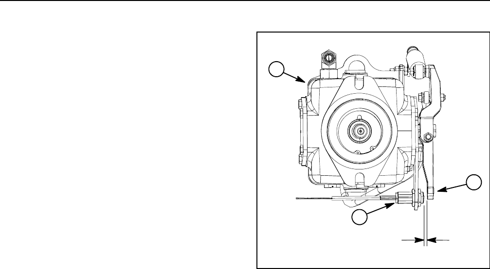
Reelmaster 5010- HPage 5 - 42Electrical System
Adjustments
Traction Neutral Switch
The traction neutral switch is a normally open proximity
switch that closes when the traction pedal is in the neu-
tral position. The switch mounts to a bracket on the trac-
tion pump. The sensing element for the traction neutral
switch is the traction pump lever that is secured to the
pump control arm (Fig. 27).
Adjustment
1. Before adjusting the traction neutral switch, check
and adjust traction system neutral position (refer to
Traction Unit Operator’s Manual).
IMPORTANT: To prevent traction neutral switch
damage, make sure that no components contact
switch through entire traction pump control arm
movement.
2. When the traction lever is in the neutral position, the
clearance between the head of traction neutral switch
and the traction lever bracket should be from 0.094” to
0.100” (2.4 to 2.5 mm).
3. If clearance is incorrect, loosen jam nuts that secure
neutral switch to pump bracket. Position switch with jam
nuts to allow correct clearance between switch and trac-
tion lever bracket. Jam nuts should be torqued from 162
to198in-lb(18.4to22.4N-m). After jam nuts are tight-
ened, make sure that clearance has not changed.
4. After adjustment to the traction neutral switch, use
the InfoCenter Display to verify that traction neutral
switch and circuit wiring are functioning correctly (see
Diagnostics Screen (Engine Run item) in the InfoCenter
Display section of this chapter).
1. Traction pump
2. Traction pump lever
3. Traction neutral switch
Figure 27
2
1
3
0.094” to 0.100”
(2.4 to 2.5 mm)
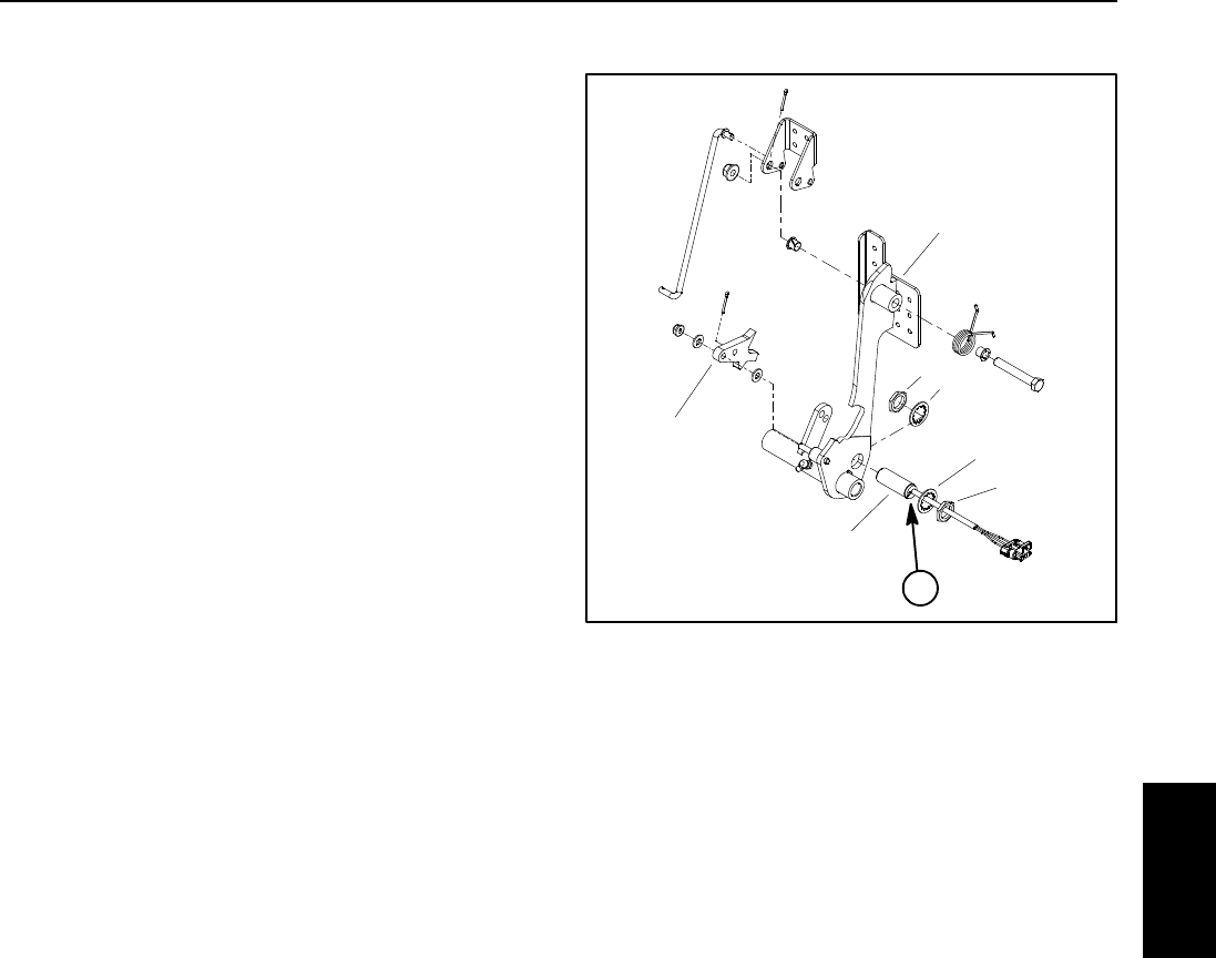
Reelmaster 5010- H Page 5 - 43 Electrical System
Parking Brake Switch
The parking brake switch is a normally open proximity
switch. The parking brake switch is attached to the bot-
tom of the brake pedal (Fig. 28).
When the parking brake is not applied, the parking brake
detent is positioned near the target end of the parking
brake switch so the switch is closed. The parking brake
detent is moved away from the switch when the parking
brake is applied causing the switch to open.
Adjustment
The distance between the parking brake switch and the
tab on the parking brake detent should be from 0.094”
to 0.100” (2.4 to 2.5 mm) when the parking brake is not
applied. If distance is incorrect, loosen jam nuts that se-
cure brake switch to brake pedal. Position switch with
jam nuts to allow correct clearance between switch and
brake detent tab. Jam nuts should be torqued from 162
to198in-lb(18.4to22.4N-m). After jam nuts are tight-
ened, make sure that clearance has not changed.
After adjustment to the parking brake switch, use the In-
foCenter Display to verify that brake switch and circuit
wiring are functioning correctly (see Diagnostics Screen
(Engine Run item) in the InfoCenter Display section of
this chapter).
1. Parking brake switch
2. Lock washer (2 used)
3. Jam nut (2 used)
4. Parking brake detent
5. Brake pedal
6. Switch LED location
Figure 28
2
3
4
5
1
2
3
6
Electrical
System
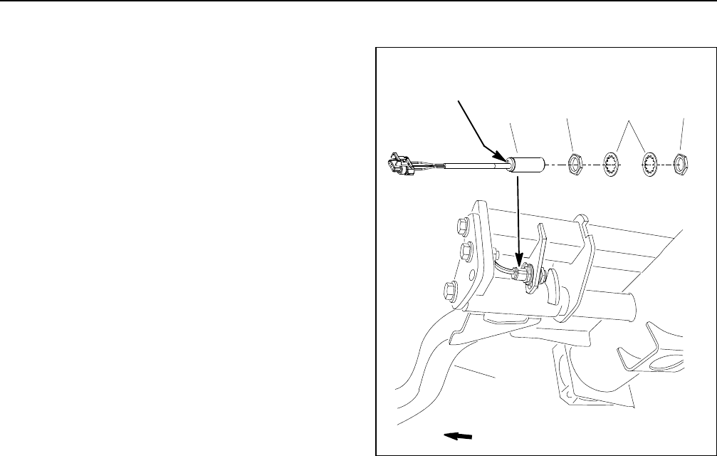
Reelmaster 5010- HPage 5 - 44Electrical System
Cutting Unit Down Limit Switch
The cutting unit down limit switch is a normally open
proximity switch that closes when the front, outside cut-
ting units are in the turn- around position. The down limit
switch is attached to a frame bracket inside the front,
right lift arm pivot tube. A bracket on the front, right lift
arm acts as the sensing plate for the down limit switch
(Fig. 29).
Adjustment
The down limit switch should be secured to the switch
bracket at the midpoint of the bracket mounting slots.
NOTE: The vertical location of the down limit switch on
the switch bracket will determine the turn- around posi-
tion of the front, outside cutting units (cutting units #4
and #5). Raising the switch on the bracket will allow a
lower turn- around position of the cutting units. Lowering
the switch on the bracket will allow a higher turn- around
position of the cutting units.
The distance between the down limit switch and the
sensing plate on lift arm should be from 0.094” to 0.100”
(2.4 to 2.5 mm). If distance is incorrect, loosen jam nuts
that secure down limit switch to machine frame. Position
switch with jam nuts to allow correct clearance between
switch and sensing plate. Jam nuts should be torqued
from 162 to 198 in- lb (18.4 to 22.4 N- m). After jam nuts
are tightened, make sure that clearance has not
changed.
After adjustment to the down limit switch, use the Info-
Center Display (see Diagnostics Screen (PTO item) in
the InfoCenter Display section of this chapter) to verify
that down limit switch and circuit wiring are functioning
correctly.
1. Down limit switch
2. Lock washer
3. Jam nut
4. Lift arm
Figure 29
LED Location
FRONT
2
3
13
4
Switch

Reelmaster 5010- H Page 5 - 45 Electrical System
Mow/Transport Switch
The mow/transport switch is a normally closed proximity
switch that is attached to the bottom of the floor platform
(Fig. 30).
When the mow stop lever is in the MOW position, the tab
on the mow stop lever is positioned away from the target
end of the mow/transport switch so the switch is closed.
The tab on the mow stop lever is moved next to the mow/
transport switch when the mow stop lever is in the
TRANSPORTpositioncausingtheswitchtoopen.
Adjustment
The distance between the mow/transport switch and the
tab on the mow stop lever should be from 0.094” to
0.100” (2.4 to 2.5 mm) when the mow stop lever is in the
TRANSPORT position. If distance is incorrect, loosen
jam nuts that secure brake switch to frame bracket.
Position switch with jam nuts to allow correct clearance
between switch and mow stop lever. Jam nuts should be
torqued from 162 to 198 in- lb (18.4 to 22.4 N- m).After
jam nuts are tightened, make sure that clearance has
not changed and that mow stop lever does not contact
switch as it is moved between positions.
After adjustment to the mow/transport switch, use the
InfoCenter Display to verify that mow/transport switch
and circuit wiring are functioning correctly (see Diag-
nostics Screen (Hi/Low Range item) in the InfoCenter
Display section of this chapter).
1. Traction pedal
2. Mow stop lever
3. Mow/transport switch
4. Lever tab
5. Lock washer (2 used)
6. Jam nut (2 used)
Figure 30
2
1
3
FRONT
LED location
3
65
4
Electrical
System
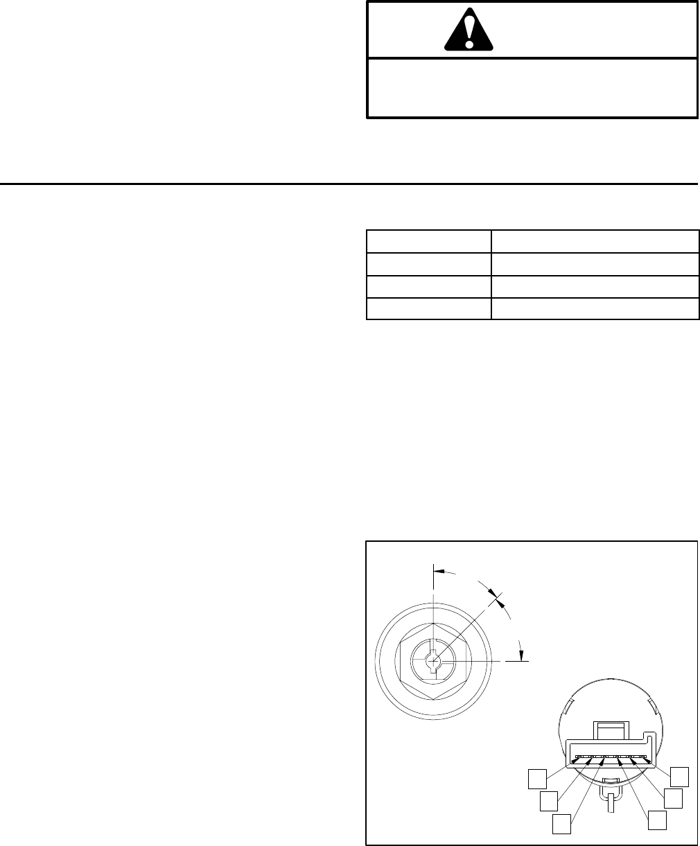
Reelmaster 5010- HPage 5 - 46Electrical System
Component Testing
For accurate resistance and/or continuity checks, elec-
trically disconnect the component being tested from the
circuit (e.g. unplug the ignition switch connector before
doing a continuity check of the switch).
NOTE: Electrical troubleshooting of any 12 volt power
connection can be performed through voltage drop tests
without disconnecting the component.
NOTE: Use the InfoCenter display to test TEC con-
troller inputs and outputs before further troubleshooting
of an electrical problem on your Reelmaster. Inputs and
outputs can be tested using the InfoCenter Diagnostic
menu (see InfoCenter Display in this chapter).
NOTE: See the Kubota Workshop Manual, Diesel En-
gine, 05- E4B Series for engine electrical component re-
pair information.
CAUTION
When testing electrical components for continu-
ity with a multimeter (ohms setting), make sure
that power to the circuit has been disconnected.
Ignition Switch
The ignition (key) switch has three (3) positions (OFF,
ON/PREHEAT and START). The switch is mounted on
the control console. The Toro Electronic Controller
(TEC) monitors the operation of the ignition switch.
Testing
NOTE: Before disconnecting the ignition switch for
testing, the switch and its circuit wiring should be tested
as a TEC input with the InfoCenter Display (see Diag-
nostics Screen (Engine Start item) in the InfoCenter Dis-
play section of this chapter). If the InfoCenter Display
verifies that the ignition switch and circuit wiring are
functioning correctly, no further switch testing is neces-
sary. If the InfoCenter Display determines that the igni-
tion switch and circuit wiring are not functioning
correctly, proceed with ignition switch testing using the
following steps.
1. Park the machine on a level surface, engage the
parking brake, lower the cutting units and stop the en-
gine. Remove the key from the ignition switch.
2. Remove outside control arm cover to gain access to
ignition switch (see Control Arm in the Service and Re-
pairs section of Chapter 6 - Chassis).
3. Disconnect wire harness connector from the ignition
switch.
4. With the use of a multimeter (ohms setting), the
switch functions may be tested to determine whether
continuity exists between the various terminals for each
ignition switch position. The ignition switch terminals are
marked as shown in Figure 31. The circuitry of this
switch is shown in the chart below. Verify continuity be-
tween switch terminals.
POSITION CIRCUIT
OFF NONE
ON/PREHEAT B+I+A, X+Y
START B+I+S
5. Replace ignition switch if testing determines that the
switch is faulty.
6. If ignition switch tests correctly and circuit problem
still exists, check wire harness (see Electrical Schemat-
ic and Circuit Drawings in Chapter 9 - Foldout Draw-
ings).
7. After ignition switch testing is complete, connect wire
harness connector to the ignition switch. Install control
arm cover to machine (see Control Arm in the Service
and Repairs section of Chapter 6 - Chassis).
Figure 31
S
B
I
A
Y
X
45
45
ON/PREHEAT
START
OFF
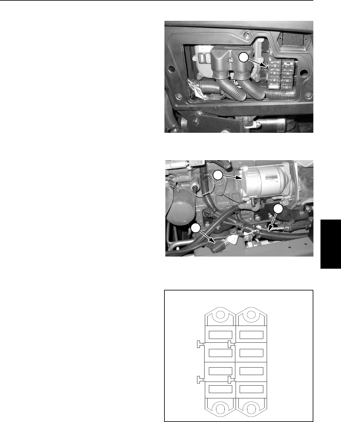
Reelmaster 5010- H Page 5 - 47 Electrical System
12 VDC System Fuses
The fuse block is located behind the control arm access
cover (Fig. 32).
In addition to the 12 VDC fuses in the fuse block, a 2
Amp fuse is included in the wire harness to protect the
logic power circuit for the TEC controller. This fuse re-
sides in a fuse holder near the engine starter motor and
issecuredtothewireharnesswithacabletie(Fig.33).
Identification and Function
The fuses are held in the fuse block. Use Figure 34 to
identify each individual fuse and its correct amperage.
Fuses for your Reelmaster have the following function:
Left Fuse 1 (15 Amp): Protects main and starter cir-
cuit power supply.
Left Fuse 2 (10 Amp): Protects main power supply.
Left Fuse 3 (10 Amp): Protects power supply for
headlights.
Left Fuse 4 (10 Amp): Protects power supply for
power point.
Right Fuse 1 (7.5 Amp): Protects power supply for
TEC controller outputs.
Right Fuse 2 (7.5 Amp): Protects power supply for
TEC controller outputs.
Right Fuse 3 (7.5 Amp): Protects power supply for
TEC controller outputs.
Right Fuse 4: Available for 20 Amp fuse used with
optional power operator seat.
Fuse Testing
1. Make sure that ignition switch is in the OFF position
and key is removed from ignition switch.
2. Remove control arm access cover to locate fuses.
3. Remove fuse(s) from the fuse block for testing. Fuse
should have continuity between fuse terminals.
4. After fuse testing is completed, install control arm ac-
cess cover.
1. Fuse block
Figure 32
1
1. Fuse
2. Main wire harness
3. Starter motor
Figure 33
2
1
3
Figure 34
7.5A
4
3
2
1
10A
10A
10A
15A
LEFT RIGHT
4
3
2
1
7.5A
7.5A
Electrical
System
Reelmaster 5010- HPage 5 - 48Electrical System
48 VDC System Fuses
Several fuses are used in the 48 VDC system (motor/
generator and cutting unit motors) for circuit protection.
Fuse Identification and Function
35 Amp Reel Motor Fuses: Protect the 48 VDC
power supply circuits for the electric reel motors. The
reel motor fuses are located in a fuse holder behind
the hood saddle under the hood (Fig. 35).
10 Amp Logic Relay Fuse: Protects the 48 VDC
logic circuit for the motor/generator and main contac-
tor, The logic relay fuse is located in an in- line fuse
holder attached near the reel motor fuse holder (Fig.
35).
250 Amp Maxi Fuse: Protects main 48 VDC power
supply. The 250 amp fuse is connected to the isolator
terminal and the main contactor behind the 48 VDC
battery disconnect attached to the right side frame
rail (Fig. 36).
Fuse Testing
1. Make sure that ignition switch is in the OFF position
and key is removed from ignition switch.
2. To prevent unexpected 48 VDC system component
operation, unplug the 48 VDC battery disconnect (see
48 VDC Battery Disconnect in the General Information
section of this chapter).
3. Locate and remove fuse(s) for testing. Fuse should
have continuity between fuse terminals. Replace fuse if
testing determines that it is faulty.
4. After fuse testing is completed, install removed cov-
ers and plug the 48 VDC battery disconnect into the
socket.
1. Hood saddle
2. Reel motor fuses
3. Logic relay fuse
Figure 35
21
3
1. RH frame rail
2. 48V battery disconnect
3. 250A fuse
4. Main contactor
Figure 36
2
1
FRONT
4
3
Reelmaster 5010- H Page 5 - 49 Electrical System
Engine Speed Switch
The engine speed switch is a momentary switch that is
used as an input for the TEC controller to raise or lower
the engine speed. When the switch is depressed and
held in the forward position, the engine speed will in-
crease. Conversely, when the rear of the switch is de-
pressed, engine speed will decrease. The engine speed
switch is located on the control arm (Fig. 37).
Testing
1. Park the machine on a level surface, engage the
parking brake, lower the cutting units and stop the en-
gine. Remove the key from the ignition switch.
2. Disassemble control arm to gain access to engine
speedswitch(seeControlArmintheServiceandRe-
pairs section of Chapter 6 - Chassis).
3. Disconnect wire harness connector from the engine
speed switch.
4. The speed switch terminals are marked as shown in
Figure 38. The circuit logic of the switch is shown in the
chart below. With the use of a multimeter (ohms setting),
the switch functions may be tested to determine whether
continuity exists between the various terminals for each
position. Verify continuity between switch terminals. Re-
place switch if testing identifies that switch is faulty.
SWITCH
POSITION
CLOSED
CIRCUITS
OPEN
CIRCUITS
FRONT OF
SWITCH
PRESSED
2+3
5+6
2+1
5+4
NEUTRAL NONE ALL
REAR OF
SWITCH
PRESSED
2+1
5+4
2+3
5+6
5. If speed switch tests correctly and circuit problem still
exists, check circuit wire harness (see Electrical
Schematic and Wire Harness Drawings in Chapter 9 -
Foldout Drawings).
6. After testing is completed, connect wire harness
connector to the switch.
7. Assemble control arm (see Control Arm in the Ser-
vice and Repairs section of Chapter 6 - Chassis).
1. Console arm 2. Engine speed switch
Figure 37
2
1
Figure 38
BACK OF SWITCH
NOTE: Reel engine speed switch terminals 4, 5 and 6
are not used on Reelmaster 5010- H machines.
Electrical
System
Reelmaster 5010- HPage 5 - 50Electrical System
Reel Engage/Disengage Switch
The reel engage/disengage switch is used to allow the
cutting units to operate. An indicator light on the switch
identifies when the engage/disengage switch is en-
gaged. The reel engage/disengage switch is mounted
on the control panel (Fig. 39). The Toro Electronic Con-
troller (TEC) monitors the operation of the reel engage/
disengage switch.
NOTE: To raise or lower the cutting units, the operator
seat has to be occupied. Also, to lower the cutting units,
thetractionspeedhastobeinLOW(mow)range.
Testing
NOTE: Before disconnecting the reel engage/disen-
gage switch for testing, the switch and its circuit wiring
should be tested as a TEC input with the InfoCenter Dis-
play (see Diagnostics Screen (PTO item) in the InfoCen-
ter Display section of this chapter). If the InfoCenter
Display verifies that the engage/disengage switch and
circuit wiring are functioning correctly, no further switch
testing is necessary. If the InfoCenter Display deter-
mines that the engage/disengage switch and circuit wir-
ing are not functioning correctly, proceed with
engage/disengage switch testing using the following
steps.
1. Park the machine on a level surface, engage the
parking brake, lower the cutting units and stop the en-
gine. Remove the key from the ignition switch.
2. Remove control arm covers to gain access to en-
gage/disengage switch (see Control Arm in the Service
and Repairs section of Chapter 6 - Chassis).
3. Disconnect wire harness connector from the en-
gage/disengage switch.
4. With the use of a multimeter (ohms setting), the
switch functions can be tested to determine whether
continuity exists between the various terminals for each
switch position. The reel engage/disengage switch ter-
minals are marked as shown in Figure 40. The circuitry
of this switch is shown in the chart below. Verify continu-
ity between switch terminals.
SWITCH
POSITION
NORMAL
CIRCUITS
OTHER
CIRCUITS
ON 2+3 5+6
OFF 2+1 5+4
5. Replace reel engage/disengage switch if testing de-
termines that it is faulty.
6. If engage/disengage switch tests correctly and cir-
cuit problem still exists, check circuit wire harness (see
Electrical Schematic and Circuit Drawings in Chapter 9
- Foldout Drawings).
7. After reel engage/disengage switch testing is com-
pleted, connect wire harness connector to the reel en-
gage/disengage switch. Install control arm cover to
machine (see Control Arm in the Service and Repairs
section of Chapter 6 - Chassis).
Figure 39
1
2
1. Console arm 2. Reel switch
Figure 40
BACK OF SWITCH
NOTE: Reel engage/disengage switch terminals 1 and
4 are not used on Reelmaster 5010- H machines.
Reelmaster 5010- H Page 5 - 51 Electrical System
Headlight Switch
The headlight switch allows the headlights to be turned
on and off. This rocker switch is located on the operator
side of the control arm (Fig. 41).
NOTE: The Toro Electronic Controller (TEC) does not
monitor the operation of the headlight switch.
Testing
1. Park the machine on a level surface, engage the
parking brake, lower the cutting units and stop the en-
gine. Remove the key from the ignition switch.
2. Remove inside control arm cover to gain access to
headlight switch (see Control Arm in the Service and Re-
pairs section of Chapter 6 - Chassis).
3. Disconnect wire harness connector from the head-
light switch.
4. With the use of a multimeter (ohms setting), the
headlight switch functions may be tested to determine
whether continuity exists between the various terminals
foreachswitchposition.Theswitchterminalsare
marked as shown in Figure 42. The circuitry of the head-
light switch is shown in the chart below. Verify continuity
between switch terminals.
SWITCH
POSITION
NORMAL
CIRCUITS
OTHER
CIRCUITS
ON 2+3 5+6
OFF 2+1 5+4
5. Replace headlight switch if testing determines that it
is faulty.
6. When headlight switch testing is complete, connect
wire harness connector to the switch. Install control arm
cover to machine (see Control Arm in the Service and
Repairs section of Chapter 6 - Chassis).
1. Console arm 2. Headlight switch
Figure 41
1
2
Figure 42
BACK OF SWITCH
NOTE: Headlight switch terminals 1, 4, 5 and 6 are not
used on Reelmaster 5010- H machines.
Electrical
System
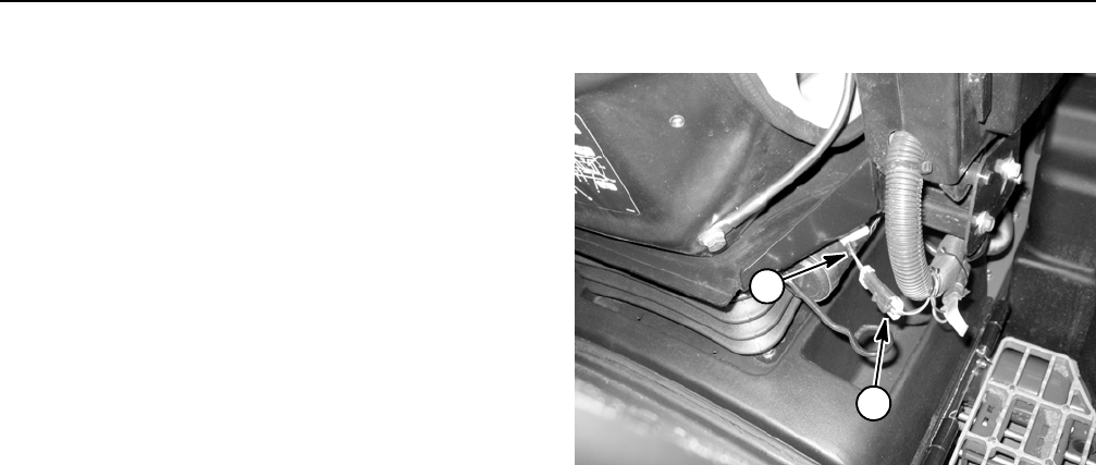
Reelmaster 5010- HPage 5 - 52Electrical System
Seat Switch
The seat switch is normally open and closes when the
operator seat is occupied. If the traction system or reel
engage/disengage switch is engaged when the opera-
tor raises out of the seat, the engine will stop. The seat
switch is located directly under the operator seat. The
Toro Electronic Controller (TEC) monitors the operation
of the seat switch.
Testing
NOTE: Before disconnecting the seat switch for test-
ing,theswitchanditscircuitwiringshouldbetestedas
a TEC input with the InfoCenter Display (see Diagnos-
tics Screen (PTO item) in the InfoCenter Display section
of this chapter). If the InfoCenter Display verifies that the
seat switch and circuit wiring are functioning correctly,
no further switch testing is necessary. If the InfoCenter
Display determines that the seat switch and circuit wir-
ing are not functioning correctly, proceed with seat
switch testing using the following steps.
1. Park the machine on a level surface, engage the
parking brake, lower the cutting units and stop the en-
gine. Remove the key from the ignition switch.
2. Disconnect wire harness connector from the seat
switch electrical lead near the manual tube under the
operator seat (Fig. 43).
3. Check the continuity of the switch by connecting a
multimeter (ohms setting) across the switch connector
terminals.
4. With no pressure on the seat, there should be no
continuity between the seat switch terminals.
5. Press directly onto the seat switch through the seat
cushion. There should be continuity between the seat
switch terminals as the seat cushion approaches the
bottom of its travel.
6. If testing determines that seat switch is faulty, re-
place switch (see Operator Seat in the Service and Re-
pairs section of Chapter 6 - Chassis).
7. If the seat switch tests correctly and a circuit problem
still exists, check circuit wire harness (see Electrical
Schematic and Wire Harness Drawings in Chapter 9 -
Foldout Drawings).
8. When seat switch testing is complete, connect wire
harness connector to the seat switch electrical lead.
1. Seat switch lead 2. Electrical connector
Figure 43
1
2
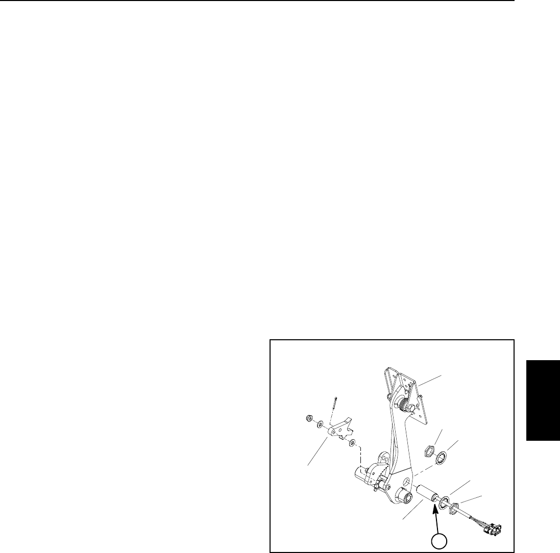
Reelmaster 5010- H Page 5 - 53 Electrical System
Parking Brake Switch
The parking brake switch is a normally open proximity
switch. The parking brake switch is attached to the bot-
tom of the brake pedal (Fig. 44). The Toro Electronic
Controller (TEC) monitors the operation of the parking
brake switch.
When the parking brake is not applied, the parking brake
detent is positioned near the target end of the parking
brake switch so the switch is closed. The parking brake
detent is moved away from the switch when the parking
brake is applied causing the switch to open.
Testing
NOTE: Before disconnecting the parking brake switch
for testing, the switch and its circuit wiring should be
tested as a TEC controller input with the InfoCenter Dis-
play (see Diagnostics Screen (Backlap item) in the Info-
Center Display section of this chapter). If the InfoCenter
Display verifies that the parking brake switch and circuit
wiring are functioning correctly, no further brake switch
testing is necessary. If the InfoCenter Display deter-
mines that the parking brake switch and circuit wiring
are not functioning correctly, proceed with parking
brake switch testing using the following steps.
1. Park the machine on a level surface, engage the
parking brake, lower the cutting units and stop the en-
gine.
2. Turn ignition switch to the ON/PREHEAT position (do
not start engine) and check LED on cable end of parking
brake switch.
A. Switch LED should be illuminated when the
parking brake is released (brake not applied).
B. Switch LED should not be illuminated when the
parking brake pedal is depressed (brake applied).
3. If the parking brake switch LED did not function cor-
rectly:
A. Make sure that parking brake switch is properly
adjusted (see Parking Brake Switch in the Adjust-
ments section of this chapter). If necessary, adjust
switchandreturntostep2above.
B. Make sure ignition switch is OFF and disconnect
the parking brake switch connector from the ma-
chinewireharness.
C. Using a multimeter, verify that the machine wire
harness connector terminal for black wire is closed
(continuity) to ground.
D. Turn ignition switch to the ON/PREHEAT position
(do not start engine) and verify with a multimeter that
machine wire harness connector terminal for parking
brake switch pink wire has system voltage (12 VDC)
present.
E. Turn ignition switch to the OFF position.
F. If black wire is closed to ground, pink wire has
system voltage present and switch LED did not func-
tion, replace parking brake switch. Adjust switch dur-
inginstallation(seeParkingBrakeSwitchinthe
Adjustments section of this chapter).
4. If the parking brake switch tests correctly and a cir-
cuit problem still exists, check circuit wire harness (see
Electrical Schematic and Wire Harness Drawings in
Chapter 9 - Foldout Drawings).
5. Make sure that wire harness electrical connector is
connected to the parking brake switch.
1. Parking brake switch
2. Lock washer (2 used)
3. Jam nut (2 used)
4. Parking brake detent
5. Brake pedal
6. Switch LED location
Figure 44
6
2
3
4
5
1
2
3
Electrical
System
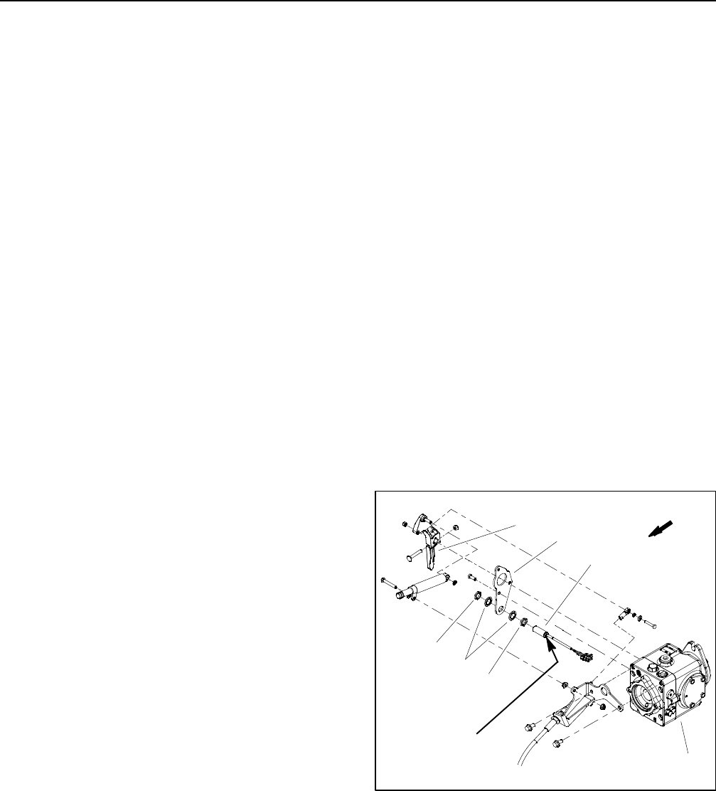
Reelmaster 5010- HPage 5 - 54Electrical System
Traction Neutral Switch
The traction neutral switch is a normally open proximity
switch that closes when the traction pedal is in the neu-
tral position. The switch mounts to the pump plate on the
piston (traction) pump. The sensing element for the trac-
tion neutral switch is the traction pump lever that is se-
cured to the pump control arm (Fig. 45). The Toro
Electronic Controller (TEC) monitors the operation of
the traction neutral switch.
Testing
NOTE: Before disconnecting the traction neutral switch
for testing, the switch and its circuit wiring should be
tested as a TEC controller input with the InfoCenter Dis-
play (see Diagnostics Screen (Engine Start item) in the
InfoCenter Display section of this chapter). If the Info-
Center Display verifies that the traction neutral switch
and circuit wiring are functioning correctly, no further
neutral switch testing is necessary. If the InfoCenter Dis-
play determines that the traction neutral switch and cir-
cuit wiring are not functioning correctly, proceed with
neutral switch testing using the following steps.
1. Park the machine on a level surface, engage the
parking brake, lower the cutting units and stop the en-
gine.
2. Tilt operator seat to gain access to traction neutral
switch.
3. Turn ignition switch to the ON/PREHEAT position (do
not start engine) and check LED on cable end of traction
neutral switch.
A. Switch LED should be illuminated when the trac-
tion pedal is in the neutral position.
B. Switch LED should not be illuminated when the
traction pedal is in either the forward or reverse posi-
tion.
4. If the neutral switch LED did not function correctly:
A. Make sure that traction neutral switch is properly
adjusted (see Traction Neutral Switch in the Adjust-
ments section of this chapter). If necessary, adjust
switchandreturntostep3above.
B. Make sure ignition switch is OFF and disconnect
the traction neutral switch connector from the ma-
chine wire harness.
C. Using a multimeter, verify that the machine wire
harness connector terminal for black wire is closed
(continuity) to ground.
D. Turn ignition switch to the ON/PREHEAT position
(do not start engine) and verify with a multimeter that
machine wire harness connector terminal for neutral
switch pink wire has system voltage (12 VDC) pres-
ent.
E. Turn ignition switch to the OFF position.
F. If black wire is closed to ground, pink wire has
system voltage present and switch LED did not func-
tion, replace traction neutral switch. Adjust switch
during installation (see Traction Neutral Switch in the
Adjustments section of this chapter).
5. If the traction neutral switch tests correctly and a cir-
cuit problem still exists, check circuit wire harness (see
Electrical Schematic and Wire Harness Drawings in
Chapter 9 - Foldout Drawings).
6. Make sure that wire harness electrical connector is
connected to the traction neutral switch. Lower operator
seat.
Figure 45
FRONT
1. Piston (traction) pump
2. Traction neutral switch
3. Traction pump lever
4. Pump plate
5. Jam nut (2 used)
6. Lock washer (2 used)
LED location
2
3
4
5
1
6
5
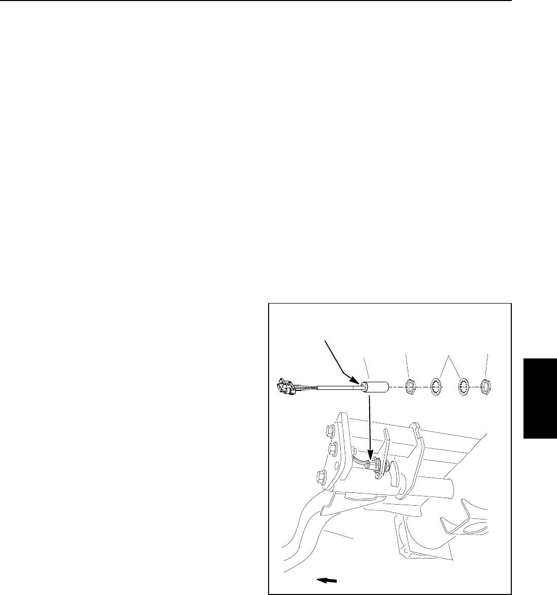
Reelmaster 5010- H Page 5 - 55 Electrical System
Cutting Unit Down Limit Switch
The cutting unit down limit switch is a normally open
proximity switch that closes when the front, outside cut-
ting units are in the turn- around position. The down limit
switch is attached to a frame bracket inside the front,
right lift arm pivot tube. A bracket on the front, right lift
arm acts as the sensing plate for the down limit switch
(Fig. 46). The Toro Electronic Controller (TEC) monitors
the operation of the cutting unit down limit switch.
Testing
NOTE: Before disconnecting the cutting unit down limit
switch for testing, the switch and its circuit wiring should
be tested as a TEC controller input with the InfoCenter
Display (see Diagnostics Screen (Backlap item) in the
InfoCenter Display section of this chapter). If the Info-
Center Display verifies that the down limit switch and cir-
cuit wiring are functioning correctly, no further down limit
switch testing is necessary. If the InfoCenter Display de-
termines that the down limit switch and circuit wiring are
not functioning correctly, proceed with down limit switch
testing using the following steps.
1. Park the machine on a level surface, engage the
parking brake, lower the cutting units and stop the en-
gine.
2. Test cutting unit down limit switch as follows:
A. Turn ignition switch to the ON position (do not
start engine) and check LED on cable end of down
limit switch.
B. LED should be illuminated when the cutting units
are lowered. LED should not be illuminated when
the cutting units are raised to the turn around posi-
tion.
3. If the cutting unit down limit switch LED did not func-
tion correctly:
A. Make sure that down limit switch is properly ad-
justed (see Cutting Unit Down Limit Switch in the Ad-
justments section of this chapter). If necessary,
adjust switch and return to step 2 above.
B. Make sure ignition switch is OFF and disconnect
the down limit switch connector from the machine
wire harness.
C. Using a multimeter, verify that the machine wire
harness connector terminal for black wire is closed
(continuity) to ground.
D. Turn ignition switch to the ON/PREHEAT position
(do not start engine) and verify with a multimeter that
machine wire harness connector terminal for down
limit switch pink wire has system voltage (12 VDC)
present.
E. Turn ignition switch to the OFF position.
F. If black wire is closed to ground, pink wire has
system voltage present and switch LED did not func-
tion, replace cutting unit down limit switch. Adjust
switch during installation (see Cutting Unit Down
Limit Switch in the Adjustments section of this chap-
ter).
4. If the down limit switch tests correctly and a circuit
problem still exists, check circuit wire harness (see Elec-
trical Schematic and Wire Harness Drawings in Chapter
9 - Foldout Drawings).
5. Make sure that wire harness electrical connector is
connected to the down limit switch after testing.
1. Down limit switch
2. Lock washer
3. Jam nut
4. Lift arm
Figure 46
LED Location
FRONT
2
3
13
4
Switch
Electrical
System
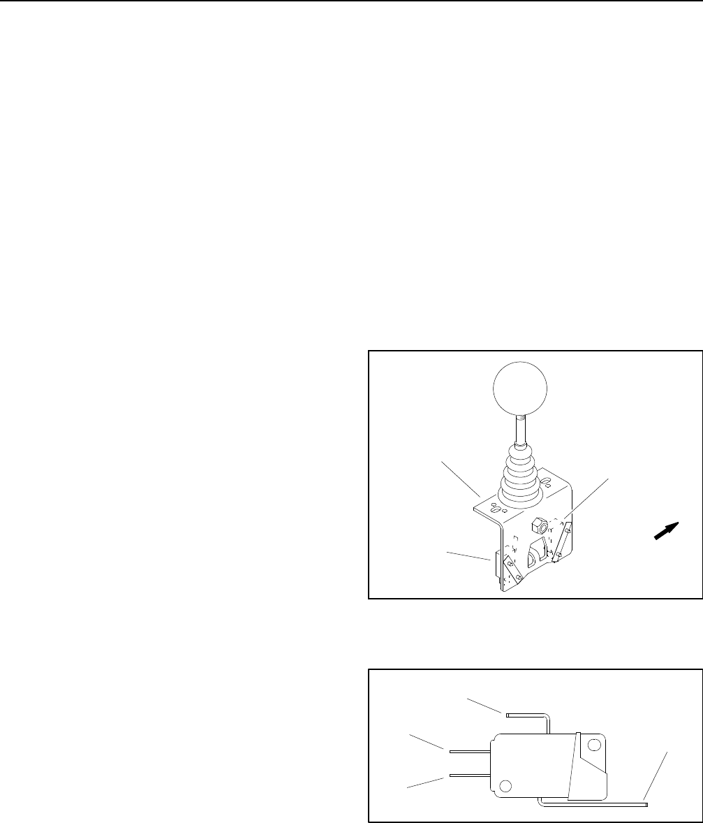
Reelmaster 5010- HPage 5 - 56Electrical System
Joystick Raise and Lower Switches
Two (2) micro switches for the joystick are located on the
lower mow/raise lever that is attached to the control arm.
The rear switch on the control is used to lower (and en-
gage) the cutting units and the front switch to raise (and
disengage) them. A normally open contact in the switch
closes when the joystick is positioned to either lower or
raise the cutting units. Each switch has an electrical con-
nector to make sure the normally closed contact on the
switch is not used. The raise switch has pink/blue and
black harness wires connected to it and the lower switch
has orange/white and black harness wires connected to
it. The Toro Electronic Controller (TEC) monitors the op-
eration of the joystick switches.
NOTE: To raise or lower the deck sections, the operator
seat has to be occupied. Also, to lower the cutting deck
sections, the traction speed has to be in LOW (mow)
range.
Testing
NOTE: Before disconnecting the joystick switches for
testing, the switches and their circuit wiring should be
tested as a TEC controller input with the InfoCenter Dis-
play (see Diagnostics Screen (Cutting Units item) in the
InfoCenter Display in this chapter). If the InfoCenter Dis-
play verifies that the joystick switches and circuit wiring
are functioning correctly, no further switch testing is nec-
essary. If the InfoCenter Display determines that either
joystick switch and circuit wiring are not functioning cor-
rectly, proceed with testing procedure
1. Park the machine on a level surface, engage the
parking brake, lower the cutting units and stop the en-
gine. Remove the key from the ignition switch.
2. Remove control arm covers to gain access to joys-
tick switches (see Control Arm in the Service and Re-
pairs section of Chapter 6 - Chassis).
3. Disconnect wire harness electrical connector from
theraiseorlowerswitchthatistobetested(Fig.47).
4. Connect a multimeter (ohms setting) across the nor-
mally open (NO) and common terminals of the switch
(Fig. 48).
5. With the joystick in the neutral (center) position,
there should be no continuity across the switch termi-
nals.
6. Move and hold the joystick to activate the switch be-
ing tested. There should be continuity across the switch
terminals.
7. If testing determines that joystick switch is faulty, re-
place switch.
8. If the joystick switch tests correctly and a circuit prob-
lem still exists, check wire harness (see Electrical Sche-
matic and Circuit Drawings in Chapter 9 - Foldout
Drawings).
9. After switch testing is completed, connect wire har-
ness electrical connector to the joystick switch.
10.Install control arm covers to machine (see Control
Arm in the Service and Repairs section of Chapter 6 -
Chassis).
1. Lower mow/raise lever
2. Raise switch
3. Lower switch
Figure 47
FRONT
1
2
3
1. Common terminal
2. NO terminal
3. NC terminal
4. Switch lever
Figure 48
1
2
3
4

Reelmaster 5010- H Page 5 - 57 Electrical System
Mow/Transport Switch
The mow/transport switch is a normally closed proximity
switch that opens when the mow stop lever is placed in
the transport position. The sensing plate for the mow/
transport switch is the mow stop lever (Fig. 49). The Toro
Electronic Controller (TEC) monitors the operation of
the mow/transport switch.
Testing
NOTE: Before disconnecting the mow/transport switch
for testing, the switch and its circuit wiring should be
tested as a TEC controller input with the InfoCenter Dis-
play (see Diagnostics Screen (Hi/Low Range item) in
the InfoCenter Display section of this chapter). If the In-
foCenter Display verifies that the mow/transport switch
and circuit wiring are functioning correctly, no further
mow/transport switch testing is necessary. If the Info-
Center Display determines that the mow/transport
switch and circuit wiring are not functioning correctly,
proceed with mow/transport switch testing using the fol-
lowing steps.
1. Park the machine on a level surface, engage the
parking brake, lower the cutting units and stop the en-
gine.
2. Test mow/transport switch as follows:
A. Turn ignition switch to the ON position (do not
start engine) and check LED on cable end of mow/
transport switch.
B. LED should be illuminated when the mow stop
lever is in the mow position. LED should not be illu-
minated when the mow stop lever is in the transport
position.
3. If the mow/transport switch LED did not function cor-
rectly:
A. Make sure that mow/transport switch is properly
adjusted (see Mow/Transport Switch in the Adjust-
ments section of this chapter). If necessary, adjust
switchandreturntostep2above.
B. Make sure ignition switch is OFF and disconnect
the mow/transport switch connector from the ma-
chinewireharness.
C. Using a multimeter, verify that the machine wire
harness connector terminal for black wire is closed
(continuity) to ground.
D. Turn ignition switch to the ON/PREHEAT position
(do not start engine) and verify with a multimeter that
machine wire harness connector terminal for mow/
transport switch pink wire has system voltage (12
VDC) present.
E. Turn ignition switch to the OFF position.
F. If black wire is closed to ground, pink wire has
system voltage present and switch LED did not func-
tion, replace mow/transport switch. Adjust switch
during installation (see Mow/Transport Switch in the
Adjustments section of this chapter).
4. If the mow/transport switch tests correctly and a cir-
cuit problem still exists, check wire harness (see Electri-
cal Schematic and Wire Harness Drawings in Chapter
9 - Foldout Drawings).
5. Make sure that wire harness electrical connector is
connected to the mow/transport switch after testing.
1. Traction pedal
2. Mow stop lever
3. Mow/transport switch
4. Lock washer (2 used)
5. Jam nut (2 used)
Figure 49
2
1
3
FRONT
LED location34
5
Electrical
System
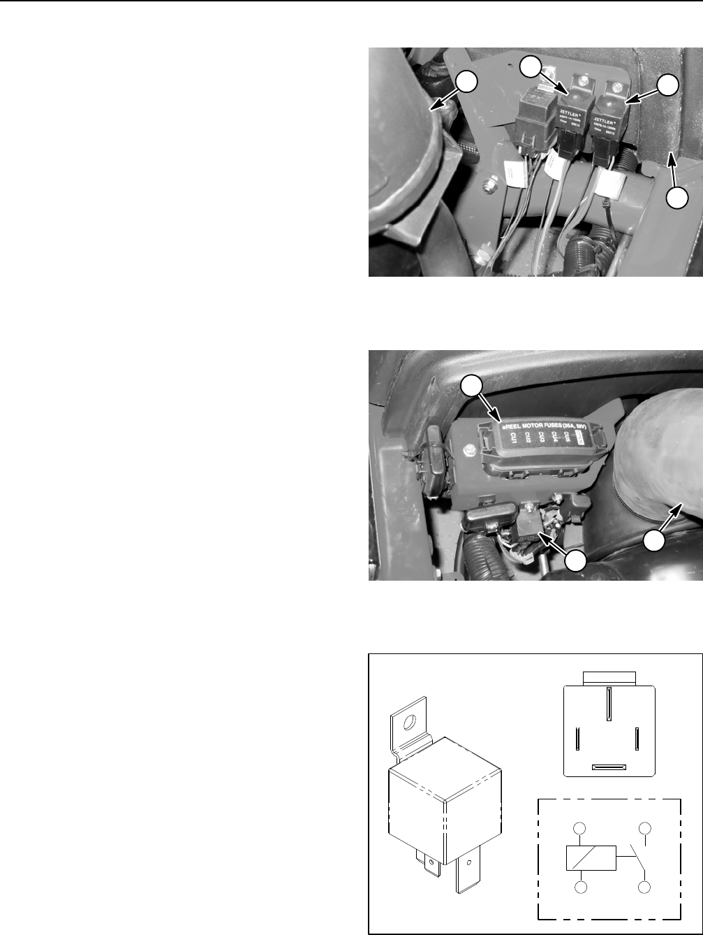
Reelmaster 5010- HPage 5 - 58Electrical System
Main Power, Glow and 48 VDC Logic Relays
Your Reelmaster uses three (3) identical electrical re-
lays that have four (4) terminals. The main power and
glow relays are attached to a frame bracket under the
hood near the engine exhaust muffler (Fig. 50). The 48
VDC logic relay is attached to a frame bracket under the
hood behind the reel motor fuse block (Fig. 51). A tag
near the relay harness connector identifies each relay.
The main power relay is used to provide current to the
TEC controller, headlights, power point and optional
electric equipment. When the ignition switch is in the
ON/PREHEAT or START position, the main power relay
is energized. A fault code will be displayed on the Info-
Center Display if the main power relay or circuit wiring
is faulty.
The glow relay is used to provide current to the engine
glow plugs when energized by the TEC controller. The
TEC controls and monitors the operation of the glow
relay. The glow relay and its circuit wiring should be
tested as a TEC output with the InfoCenter Display be-
fore disconnecting and testing the relay (see InfoCenter
Display in this chapter). A fault code may be displayed
on the InfoCenter Display if the glow relay or circuit
wiring is faulty.
The 48 VDC logic relay is used to provide 48 VDC logic
power to the motor/generator and reel motor controllers.
It also supplies power to the main contactor in the elec-
tric reel circuit. This relay is energized by an output from
the TEC controller.
Testing
1. Park the machine on a level surface, engage the
parking brake, lower the cutting units and stop the en-
gine. Remove the key from the ignition switch.
2. Open hood to gain access to relays.
3. Locate relay and disconnect the machine wire har-
ness connector from the relay. If main power or glow re-
lay are to be removed, remove hood saddle from
machine for easier access to start relay. Remove relay
from machine for easier testing.
NOTE: Prior to taking small resistance readings with a
digital multimeter, short the meter test leads together.
The meter will display a small resistance value (usually
0.5 ohms or less). This resistance is due to the internal
resistance of the meter and test leads. Subtract this val-
ue from from the measured value of the component you
are testing.
4. Verify coil resistance between terminals 85 and 86
with a multimeter (ohms setting) (Fig. 52). Resistance
should be approximately 72 ohms.
1. Exhaust muffler
2. Main power relay
3. Glow relay
4. Hood saddle
Figure 50
13
2
4
1. 48 VDC logic relay
2. Reel motor fuses
3. Generator air intake
Figure 51
2
3
1
Figure 52
86 87
85 30
85 86
87
30

Reelmaster 5010- H Page 5 - 59 Electrical System
5. Connect multimeter (ohms setting) leads to relay ter-
minals 30 and 87. Ground terminal 86 and apply +12
VDC to terminal 85. The relay should have continuity be-
tween terminals 30 and 87 as +12 VDC is applied to ter-
minal 85. The relay should not have continuity between
terminals 30 and 87 as +12 VDC is removed from termi-
nal 85.
6. When relay testing is complete, disconnect voltage
and multimeter leads from the relay terminals.
7. Replace relay if testing determines that it is faulty.
8. Secure relay to machine and connect machine wire
harness connector to relay. Install hood saddle to ma-
chine if it was removed. Lower and secure hood.
Electrical
System
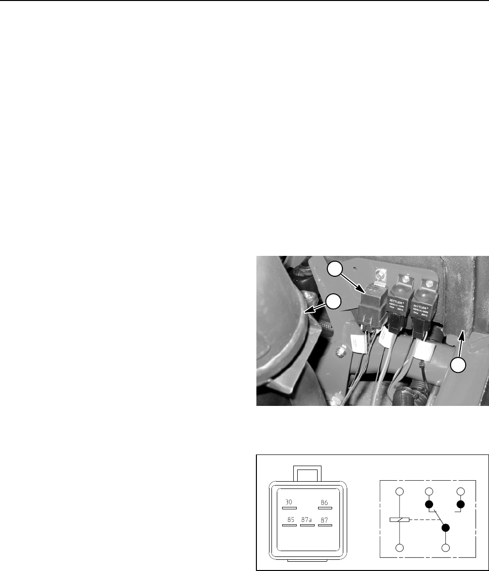
Reelmaster 5010- HPage 5 - 60Electrical System
Start Relay
The start relay is used in the engine starting circuit.
When energized by the TEC controller, the start relay
provides a current path to energize the engine starter
solenoid. The start relay has five (5) terminals and is at-
tached to a frame bracket under the hood near the en-
gine exhaust muffler (Fig. 53). Relays can be identified
byatagonthewireharness.
Testing
NOTE: The start relay should be tested as a TEC con-
troller output with the InfoCenter Display before discon-
necting and testing the relay (see Diagnostics Screen
(Engine Start item) in the InfoCenter Display section of
this chapter). The InfoCenter Display will identify if the
TEC output to the start relay exists when machine con-
trols are in the correct position. If the TEC controller out-
put exists for the start relay but the relay is not
functioning correctly, suspect a failed start relay or an
open in the start relay circuit.
1. Park the machine on a level surface, engage the
parking brake, lower the cutting units and stop the en-
gine. Remove the key from the ignition switch.
2. Open hood to gain access to start relay. Remove
hood saddle from machine for easier access to start
relay.
3. Locate start relay and disconnect the machine wire
harness connector from the relay. Remove relay from
machine for easier testing.
NOTE: Prior to taking small resistance readings with a
digital multimeter, short the meter test leads together.
The meter will display a small resistance value (usually
0.5 ohms or less). This resistance is due to the internal
resistance of the meter and test leads. Subtract this val-
ue from the measured value of the component you are
testing.
4. Using a multimeter (ohms setting), measure coil re-
sistance between terminals 85 and 86 (Fig. 54). Resist-
ance should be between 70 and 90 ohms.
5. Connect multimeter (ohms setting) leads to relay ter-
minals 30 and 87. Ground terminal 86 and apply +12
VDC to terminal 85. The relay should have continuity be-
tween terminals 30 and 87 as +12 VDC is applied to ter-
minal 85. The relay should not have continuity between
terminals 30 and 87 as +12 VDC is removed from termi-
nal 85.
6. Disconnect voltage from terminal 85 and multimeter
lead from terminal 87.
7. Connect multimeter (ohms setting) leads to relay ter-
minals 30 and 87A. Apply +12 VDC to terminal 85. The
relay should not have continuity between terminals 30
and 87A as +12 VDC is applied to terminal 85. The relay
should have continuity between terminals 30 and 87A
as +12 VDC is removed from terminal 85.
8. When testing is complete, disconnect voltage and
multimeter leads from the relay terminals.
9. Replace start relay if testing determines that it is
faulty.
10.Secure start relay to machine and connect machine
wire harness connector to relay. Install hood saddle to
machine. Lower and secure hood.
Figure 53
1. Exhaust muffler
2. Start relay
3. Hood saddle
2
1
3
Figure 54
86
85
87A 87
30
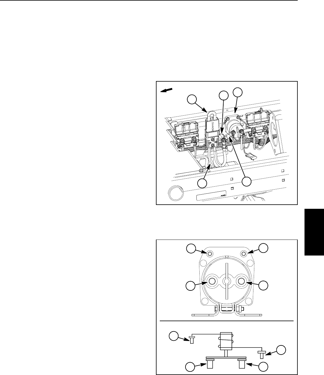
Reelmaster 5010- H Page 5 - 61 Electrical System
Main Contactor
The main contactor provides current to the 48 VDC sys-
tem circuits (e.g. motor/generator, reel motors). When
the ignition switch is ON, the 48 VDC logic relay is ener-
gized by the TEC controller which allows the main con-
tactor to be energized if allowed by the motor/generator
controller. The main contactor is attached to the right
side frame rail under the operator seat (Fig. 55).
NOTE: If electrical problems exist with the main contac-
tor, a fault may have occurred that would be indicated by
a fault code on the InfoCenter Display. Before consider-
ing that main contactor service work is necessary, check
for any existing fault codes that indicate problems with
the contactor.
Testing
1. Park the machine on a level surface, engage the
parking brake, lower the cutting units and stop the en-
gine. Remove the key from the ignition switch.
2. Raise operator seat to access main contactor.
3. Separate system components from the 48 VDC bat-
tery pack by unplugging the 48 VDC battery disconnect.
(see 48 VDC Battery Disconnect in the General Informa-
tion section of this chapter). This will prevent unex-
pected 48 VDC system component operation.
4. Remove cover from main contactor (not shown).
5. Disconnect all wire harness electrical connections
from contactor. Note wire connector locations on con-
tactor for reassembly purposes.
6. Using jumper wires, apply 48 VDC directly across the
contactor coil posts (Fig. 56). The contactor should click
as the coil is energized. With the contactor coil ener-
gized, resistance across the main contact posts should
be less than 1 ohm.
7. Remove voltage from contactor coil posts. The con-
tactor should click as the coil is de- energized. With the
contactor coil not energized, resistance across the main
contact posts should be infinite ohms.
8. With no voltage applied to contactor posts, measure
resistance across the contactor coil posts (Fig. 56). The
resistance should be approximately 126 ohms.
9. Replace main contactor if testing determines that it
is faulty.
10.Connect electrical connections to main contactor
(Fig. 56). Torque nuts that secure connections to con-
tactor main contact posts from 40 to 50 in- lb (4.6 to 5.6
N-m) and nuts that secure connections to contactor coil
posts to 20 in- lb (2.2 N- m).
11. Plug the 48 VDC battery disconnect back into the
socket. Lower and secure operator seat.
Figure 55
2
35
4
1. Main contactor
2. Positive battery cable
3. 48V battery disconnect
4. Fuse (250A / 58V)
5. Isolator
1
FRONT
Figure 56
1. Main contact posts 2. Contactor coil posts
1
1
2
2
WIRING
DIAGRAM
2
2
1
1
CONTACTOR
Electrical
System
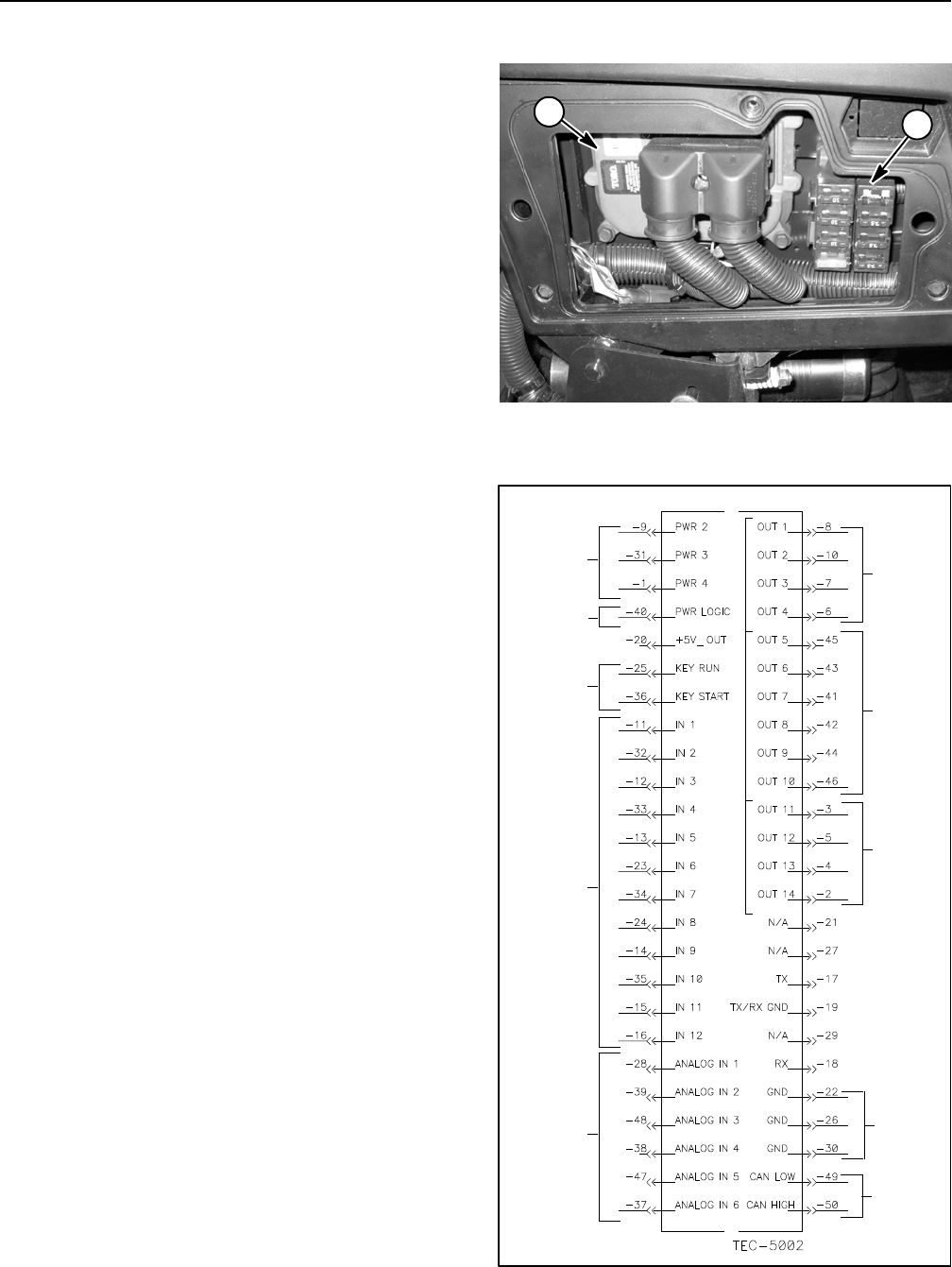
Reelmaster 5010- HPage 5 - 62Electrical System
Toro Electronic Controller (TEC)
Reelmaster 5010- H machines use a Toro Electronic
Controller (TEC) to control electrical system operation.
The TEC controller senses the condition of various
switches (inputs) and directs power output to allow cer-
tain machine functions. The TEC is attached to the con-
trol arm behind the access panel on the outside of the
control arm (Fig. 57).
Logic power is provided to the controller as long as the
battery cables are connected to the battery. A 2 Amp
fuse (fuse F4) provides circuit protection for this logic
power to the controller.
Inputs from the ignition, neutral, parking brake, reel en-
gage/disengage, seat, mow/transport, joystick lower/
raise, reels down limit, engine speed, engine
temperature sender and engine oil pressure switches
are all monitored by the TEC controller.
Current output to the lift circuit hydraulic valve solenoid
coils, engine components (glow plug relay, start relay,
fuel pump and fuel actuator) and reel circuit 48 VDC log-
ic relay are controlled based on the inputs received by
the TEC controller. Circuit protection for TEC outputs is
provided by three (3) 7.5 Amp fuses (fuse locations
F2- 1, F2- 2 and F2- 3).
The InfoCenter Display should be used when checking
inputs and outputs of the TEC used on your Reelmaster.
If the TEC detects a malfunction in any of the controlled
circuits, the InfoCenter Display can also be used to iden-
tify the fault (see InfoCenter Display in this chapter).
The diagram in Figure 58 depicts the connection termi-
nal functions for the TEC controller. Note that electrical
power for controller outputs is provided through three (3)
connections (PWR 2, PWR 3 and PWR 4) each pro-
tected with a 7.5 amp fuse. A fifty (50) pin wire harness
connector attaches to the controller. The connector pins
are identified in the diagram in Figure 58. The layout of
the wire harness connector that plugs into the TEC con-
troller is shown in Fig. 59.
IMPORTANT: When testing for wire harness con-
tinuity at the connector for the TEC controller, take
care to not damage the connector pins with multi-
meter test leads. If connector pins are enlarged or
damaged during testing, connector repair will be
necessary for proper machine operation.
The machine electrical schematic and wire harness
drawings in Chapter 10 - Foldout Drawings can be used
to identify possible circuit problems between the con-
troller and the input/output devices (e.g. switches and
solenoid coils).
1. TEC controller 2. Fuse block
Figure 57
12
Figure 58
12V POWER
(7.5A FUSES)
12V LOGIC
IGNITION
SWITCH
INPUTS
DIGITAL
INPUTS
(OPEN/
ANALOG
INPUTS
POWER
(2 AMP FUSE)
CLOSED)
(VARIABLE)
CAN BUS
OUTPUTS
(PWR2)
GROUND
OUTPUTS
(PWR3)
OUTPUTS
(PWR4)
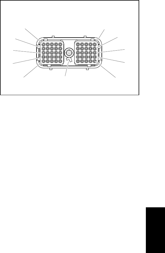
Reelmaster 5010- H Page 5 - 63 Electrical System
Because of the solid state circuitry built into the TEC
controller, there is no method to test it directly. The TEC
may be damaged if an attempt is made to test it with an
electrical test device, such as a digital multimeter.
IMPORTANT: Before performing welding on the ma-
chine, disconnect both positive and negative bat-
tery cables from the battery, disconnect both wire
harness connectors from the TEC controller and
disconnect the terminal connector from the alterna-
tor to prevent damage to the electrical system.
Figure 59
WIRE HARNESS CONNECTOR FOR
TEC CONTROLLER
11
1
21
31
41
10
50
40
30
20
POSITION
NOTE TAB
Electrical
System
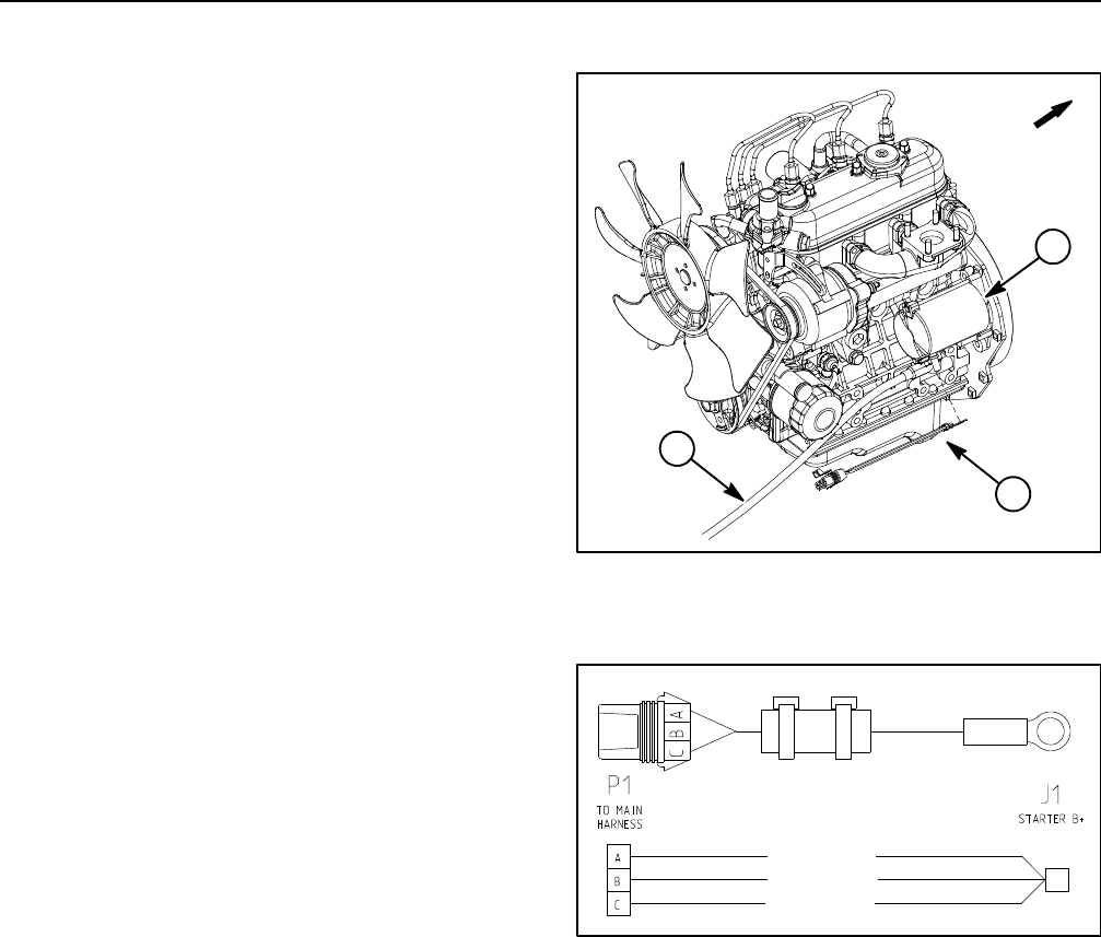
Reelmaster 5010- HPage 5 - 64Electrical System
Fusible Link Harness
The Reelmaster 5010- H uses three (3) fusible links for
circuit protection. These fusible links are located in a
harness that connects the starter B+ terminal to the
main wire harness (Fig. 60). If any of these links should
fail, current to the protected circuit will cease. Refer to
wire harness drawings in Chapter 9 - Foldout Drawings
for additional fusible link information.
Testing
1. Park the machine on a level surface, engage the
parking brake, lower the cutting units and stop the en-
gine. Remove the key from the ignition switch.
2. Disconnect negative battery cable from battery at
rear of machine. Then disconnect positive cable from
battery (see Battery Service in the Service and Repairs
section of this chapter).
3. Locate and unplug fusible link connector P1 from
platform wire harness.
4. Use a multimeter to make sure that continuity exists
between each terminal pin in connector P1 and connec-
tor J1 at the starter (Fig. 61). If any of the fusible links are
open, replace the fusible link harness.
5. After testing is complete, make sure that fusible link
harness connectors are securely attached to starter and
machine wire harness.
6. Connect positive battery cable to battery terminal
first and then connect negative cable to battery.
1. Starter motor
2. Fusible link harness
3. Positive battery cable
Figure 60
2
1
3
FRONT
Figure 61
FUSIBLE LINK
FUSIBLE LINK
FUSIBLE LINK
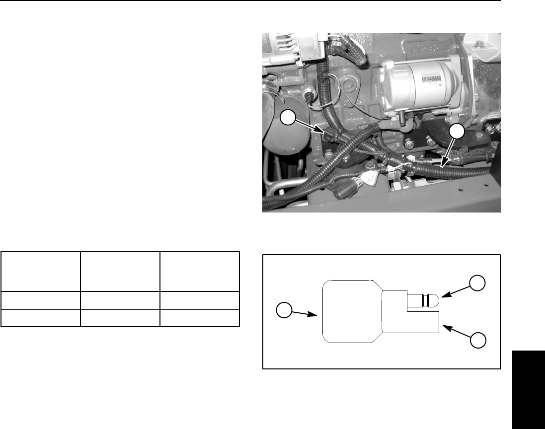
Reelmaster 5010- H Page 5 - 65 Electrical System
Diode Assembly
A diode assembly is used in the Reelmaster main wire
harness (Fig. 62). The diode is used for circuit protection
from voltage spikes that occur when the starter solenoid
is de- energized.
Testing
1. Park the machine on a level surface, engage the
parking brake, lower the cutting units and stop the en-
gine. Remove the key from the ignition switch.
2. Locate diode assembly near alternator on engine
and remove cable tie that secures diode to wire harness.
Unplug the diode from the wire harness for testing.
3. The diode (Fig. 63) can be tested using a digital
multimeter (diode test or ohms setting) and the table be-
low.
Multimeter
Red Lead (+)
on Terminal
Multimeter
Black Lead (- )
on Terminal
Continuity
Female Male YES
Male Female NO
4. If testing determines that diode is faulty, replace
diode assembly.
5. After diode testing is complete, make sure that diode
is fully installed into wire harness connector and se-
cured to harness with cable tie.
1. Main wire harness 2. Diode assembly
Figure 62
1
2
Figure 63
1. Diode
2. Male terminal
3. Female terminal
1
2
3
Electrical
System
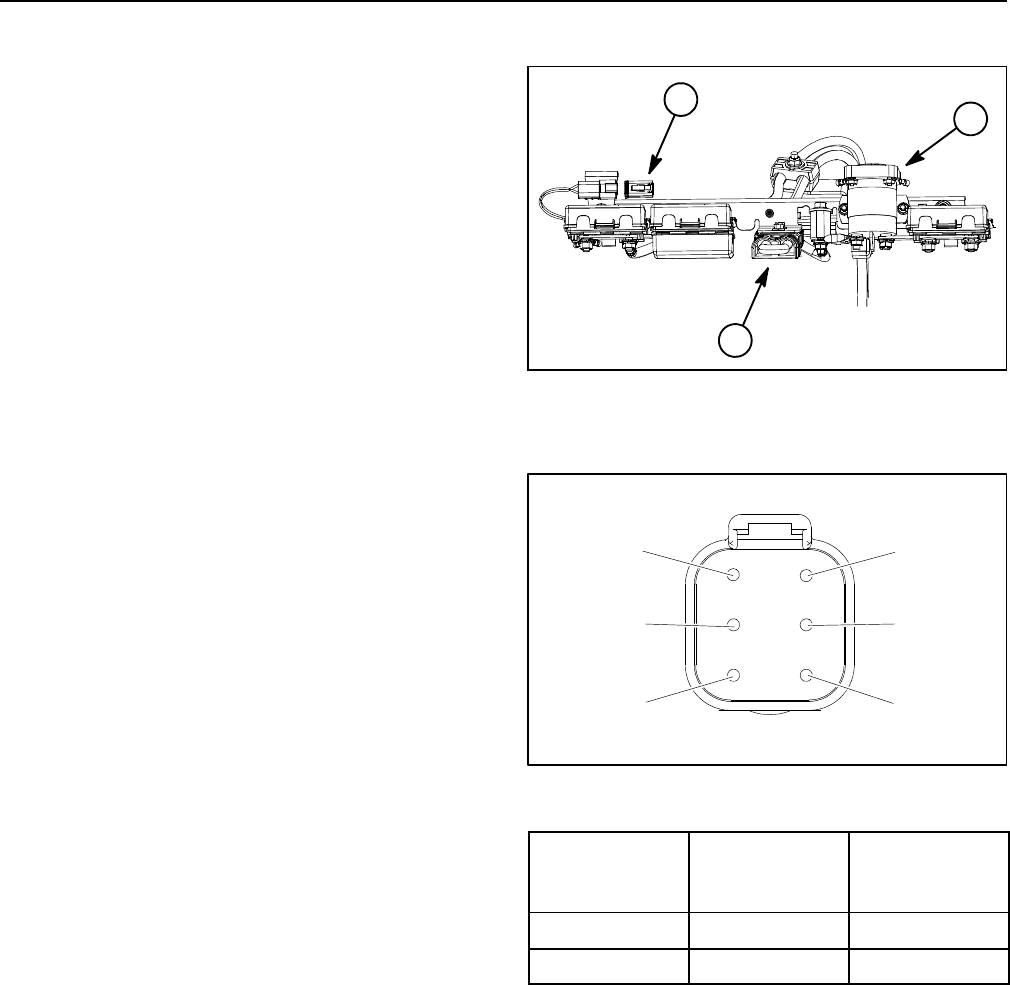
Reelmaster 5010- HPage 5 - 66Electrical System
48 VDC System Protection Diode
The Reelmaster 5010- H 48 VDC system includes a
diode that is used for circuit protection from voltage
spikes when the main contactor is de- energized. The
diode plugs into the main wire harness near the 48 VDC
battery disconnect and main contactor under the opera-
tor seat (Fig. 64).
Protection Diode Testing
1. Park the machine on a level surface, engage the
parking brake, lower the cutting units and stop the en-
gine. Remove the key from the ignition switch.
2. Raise operator seat.
3. Separate system components from the 48 VDC bat-
tery pack by unplugging the 48 VDC battery disconnect.
(see 48 VDC Battery Disconnect in the General Informa-
tion section of this chapter). This will prevent unex-
pected 48 VDC system component operation.
4. Locate protection diode near 48 VDC battery discon-
nect and unplug the diode from the wire harness for test-
ing.
5. The protection diode (Fig. 65) can be tested using a
digital multimeter (diode test or ohms setting) and the
table to the right. Replace the protection diode if testing
determines that it is faulty.
NOTE: Protection diode terminals 2, 3, 4 and 5 are not
used on Reelmaster 5010- H machines.
6. After testing is complete, make sure that protection
diode is fully installed into wire harness connector.
7. Plug the 48 VDC battery disconnect back into the
socket. Lower and secure operator seat.
1. Protection diode
2. 48V battery disconnect
3. Main contactor
Figure 64
1
2
3
Figure 65
6
5
4
2
3
1
Multimeter
Red Lead (+)
on Terminal
Multimeter
Black Lead (- )
on Terminal
Continuity
6 1 YES
1 6 NO
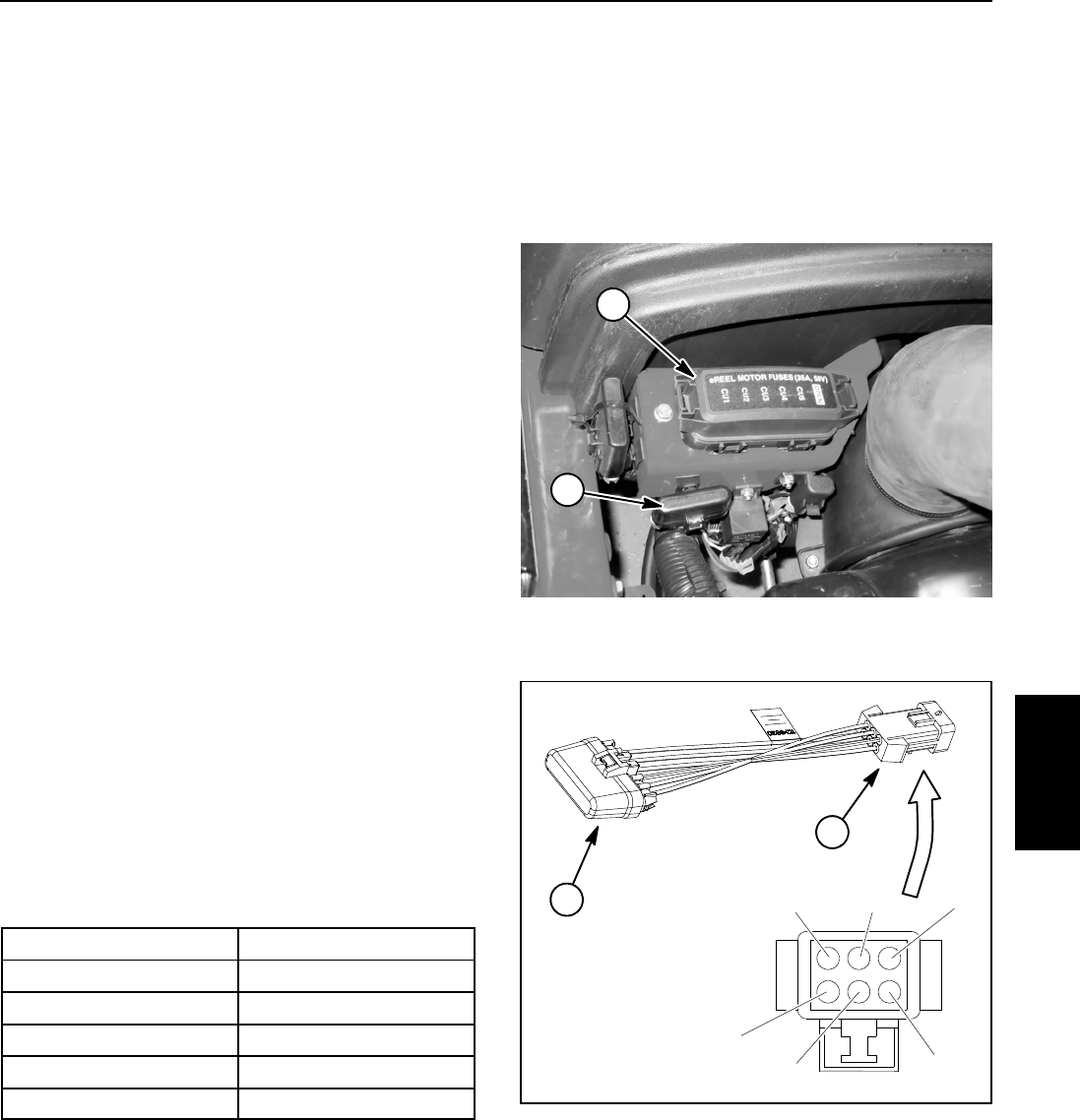
Reelmaster 5010- H Page 5 - 67 Electrical System
Location ID Module
The location ID module exists in the 48 VDC electrical
circuit to identify the location of the five (5) cutting reel
motors. This module allows such machine features as
starting and stopping the rear cutting units slightly later
than the front cutting units. The location module plugs
into the main wire harness near the 48 VDC fuse block
(Fig. 66).
NOTE: If electrical problems exist with the location ID
module, a fault may have occurred that would be indi-
cated by a fault code on the InfoCenter Display. Before
considering that location ID module service work is nec-
essary, check for any existing fault codes that indicate
problems with the module.
Testing
1. Park machine on level surface, lower cutting units,
stop engine, apply parking brake and remove key from
ignition switch.
2. Raise and support operator seat and hood.
3. Separate system components from the 48 VDC bat-
tery pack by unplugging the 48 VDC battery disconnect
(see 48 VDC Battery Disconnect in the General Informa-
tion section of this chapter). This will prevent unex-
pected cutting unit operation.
4. Locate location ID module secured to the frame near
the 48 VDC fuse block (Fig. 66).
5. Carefully unplug main wire harness connector from
location ID module connector.
6. Using a multimeter, measure resistances between
module connector terminals as follows (Fig. 67):
Connector Terminals Resistance
AandF 15 K ohms
BandF 10 K ohms
CandF 6.2 K ohms
DandF 3.9 K ohms
EandF 1.6 K ohms
7. Replace ID module if testing determines that it is
faulty.
NOTE: Do not attempt to remove cover of location ID
module. There are no replaceable parts under cover.
8. After testing is completed, secure main wire harness
connector to location ID module connector.
9. Plug the 48 VDC battery disconnect back into the
socket.
10.Lower and secure operator seat and hood.
1. Location ID module 2. 48 VDC fuse block
Figure 66
2
1
Figure 67
AB
C
D
EF
1. Location ID module 2. ID module connector
1
2
Electrical
System
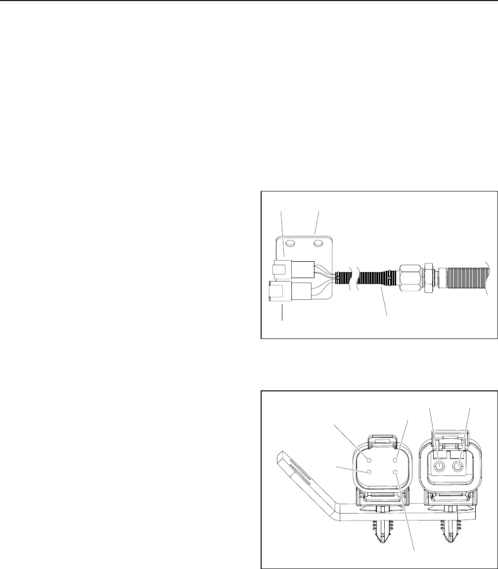
Reelmaster 5010- HPage 5 - 68Electrical System
Cutting Reel Motor
The five (5) cutting reel motors are identical 48 VDC,
brushless, permanent magnet motors. Each motor has
its own integral invertor and on- board controller. The In-
foCenter Display can be used to monitor the speed and
current draw for the five (5) cutting unit motors during
machine operation. Also, if a problem exists with any
cutting reel motor, a fault may have occurred that would
be indicated by a fault code on the InfoCenter Display.
Because the cutting reel motors used on the Reelmaster
5010- H are the same motors, motors from different cut-
ting units can be exchanged. If the problem follows a
motor to the new cutting unit, the motor is likely the is-
sue. If the problem remains with the cutting unit, the is-
sue is likely due to the cutting unit or electrical
components or wiring to that cutting unit.
NOTE: Before considering that cutting reel motor ser-
vice work is necessary, check for any existing fault
codes that indicate problems with a reel motor (see
Fault Codes in the Troubleshooting section of this chap-
ter). If a cutting reel motor is faulty, there will likely be nu-
merous fault codes that are listed by the InfoCenter
display.
Testing
1. Park machine on level surface, lower cutting units,
stop engine, apply parking brake and remove key from
ignition switch.
2. Separate system components from the 48 VDC bat-
tery pack by unplugging the 48 VDC battery disconnect
(see 48 VDC Battery Disconnect in the General Informa-
tion section of this chapter). This will prevent unex-
pected cutting unit operation.
3. Locate cutting reel motor cable electrical connec-
tions at machine wire harness for motor that is to be test-
ed.
IMPORTANT: When disconnecting reel motor cable
connectors, take care to not damage the cable or
connectors. The reel motor cable is not available as
a separate replacement part.
4. Carefully disconnect two (2) reel motor cable con-
nectors from machine wire harness (Fig. 68).
5. Using a multimeter, measure resistance between 48
VDC ground terminal (black wire) in the 2 wire connector
and location ID terminal (blue wire) in 4 wire connector
(Fig. 69). Resistance should be approximately 18.8
K- ohms.
6. If measured resistance is incorrect, consider that the
cutting reel motor is faulty.
NOTE: If cutting reel motor removal, installation, disas-
sembly or assembly information is needed, see Cutting
Reel Motor and Cutting Reel Motor Service in the Ser-
vice and Repairs section of this chapter.
7. After testing is completed, secure two (2) reel motor
cable connectors to machine wire harness connectors.
8. Plug the 48 VDC battery disconnect back into the
socket.
1. Cable from motor
2. 4 wire connector
3. 2 wire connector
4. Connector plate
Figure 68
2
31
4
1. 48 VDC ground (black)
2. 48 VDC power (red)
3. Location ID (blue)
4. 48 VDC logic (white)
5. CAN- bus (green)
6. CAN- bus (yellow)
Figure 69
2
3
1
4
5
6
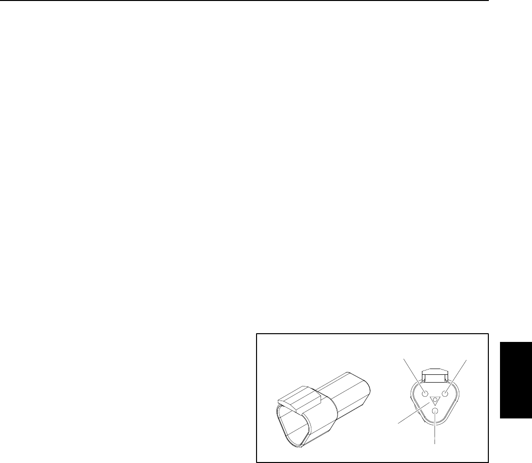
Reelmaster 5010- H Page 5 - 69 Electrical System
CAN- bus Termination Resistors
System communication between electrical components
on Reelmaster 5010- H machines is accomplished on
two (2) CAN- bus communication systems: one for the
12 VDC system and one for the 48 VDC system. Two (2)
specially designed, twisted cables form the bus for both
of the networks used on the 5010- H machines. These
wires provide the data pathways between machine elec-
trical components. At the ends of the twisted pair of bus
cables are 120 ohm termination resistors.
The twisted pair of bus wires for the 12 VDC circuits are
black/white and red/white. The twisted pair of bus wires
for the 48 VDC circuits are green and yellow.
The two (2) termination resistors for the 12 VDC electri-
cal circuits have the following locations:
A. In the control arm next to the operator seat.
B. Near the wire harness connectors for the #3 (right
rear) cutting unit motor on the right side of the ma-
chine.
The two (2) termination resistors for the 48 VDC electri-
cal circuits have the following locations:
A. Near the wire harness connectors for the #1 (front
center) cutting unit motor under the footrest at the
front of the machine.
B. Near the 48 VDC reel motor fuse holder behind
the hood saddle under the hood.
NOTE: Refer to the Electrical Schematics and Wire
Harness Drawings in Chapter 9 - Foldout Drawings for
additional information on termination resistor locations
and wire connections.
IMPORTANT: The termination resistors at the ends
of the bus cables are required for proper electrical
system operation.
Termination Resistor Test
The termination resistors (Fig. 70) can be individually
tested using a digital multimeter (ohms setting). Locate
resistor and remove cable tie that secures resistor to
wire harness. Unplug the resistor from the wire harness
for testing.
NOTE: The insulator wedge in the termination resistor
is blue for identification purposes. There also is a center
keyway to prevent the termination resistor from plugging
into the wrong wire harness connector.
Use a digital multimeter (ohms setting) to measure the
resistance value for the termination resistor. There
should be 120 ohms resistance between terminals A
and B. Refer to Fig. 70 to determine terminal locations.
Terminal C is not used on Reelmaster 5010- H ma-
chines.
If testing determines that termination resistor is faulty,
replace resistor.
After testing is complete, make sure that termination re-
sistor is fully installed into wire harness connector and
securedtowireharnesswithcabletie.
Figure 70
Termination A
B
C
Resistor
Keyway
Electrical
System
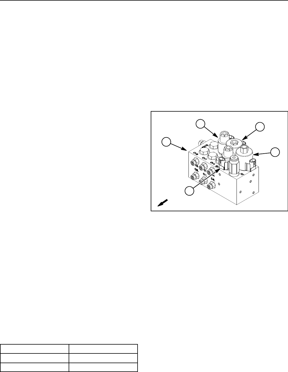
Reelmaster 5010- HPage 5 - 70Electrical System
Hydraulic Solenoid Valve Coil
The Reelmaster hydraulic lift control manifold includes
four (4) solenoid valves for system control (Fig. 71).
When the solenoid coils are energized, hydraulic valve
shift occurs to control hydraulic flow. Testing of the coils
canbedonewiththecoilinstalled on the hydraulic valve.
NOTE: If electrical problems exist with a solenoid valve
coil, a fault may have occurred that would be indicated
by a fault code on the InfoCenter Display. Before consid-
ering that solenoid valve coil service work is necessary,
check for any existing fault codes that indicate problems
withacoil.
Testing
NOTE: A solenoid valve coils should be tested as a
TEC controller output with the InfoCenter Display before
disconnecting and testing the coil (see Diagnostics
Screen (PTO item) in the InfoCenter Display section of
this chapter). The InfoCenter Display will identify if the
TEC output to the solenoid coil exists when machine
controls are in the correct position. If the TEC controller
output exists for a solenoid coil but the coil is not func-
tioning correctly, suspect a failed coil or an open in the
solenoid valve coil circuit.
1. Park machine on level surface, lower cutting units,
stop engine, apply parking brake and remove key from
ignition switch.
2. Access to the lift control manifold can be obtained by
removing the operator floor plate.
3. Disconnect wire harness electrical connector from
hydraulic solenoid valve coil that is to be tested (Fig. 71).
NOTE: Prior to taking small resistance readings with a
digital multimeter, short the meter test leads together.
The meter may display a small resistance value (usually
0.5 ohms or less). This resistance is due to the internal
resistance of the meter and test leads. Subtract this val-
ue from from the measured value of the component you
are testing.
4. Using a multimeter (ohms setting), measure resis-
tance between the two connector terminals on the sole-
noid valve coil. The resistance for the solenoid coils is
identified below:
Solenoid Valve Coil Resistance
SV1 and SV3 8.7 ohms
SV2 and SVRV 7.1 ohms
5. If solenoid coil resistance is incorrect, replace sole-
noid coil (see Hydraulic Solenoid Valve Coil in the Ser-
vice and Repairs section of this chapter).
NOTE: Solenoid valve coils SV2 and SVRV on the lift
control manifold are identical. The remaining two lift
manifold coils (SV1 and SV3) are identical. To assist in
troubleshooting, identical coils can be exchanged. If the
problem follows the exchanged coil, an electrical prob-
lem likely exists. If the problem remains unchanged,
something other than the solenoid coil is the problem
source (e.g. switch, circuit wiring, hydraulic problem).
6. After testing the coils, connect wire harness electri-
cal connector to the solenoid valve coil.
7. Install operator floor plate.
1. Lift manifold
2. SV3 solenoid
3. SV2 solenoid
4. SVRV solenoid
5. SV1 solenoid
Figure 71
4
1
3
5
2
FRONT
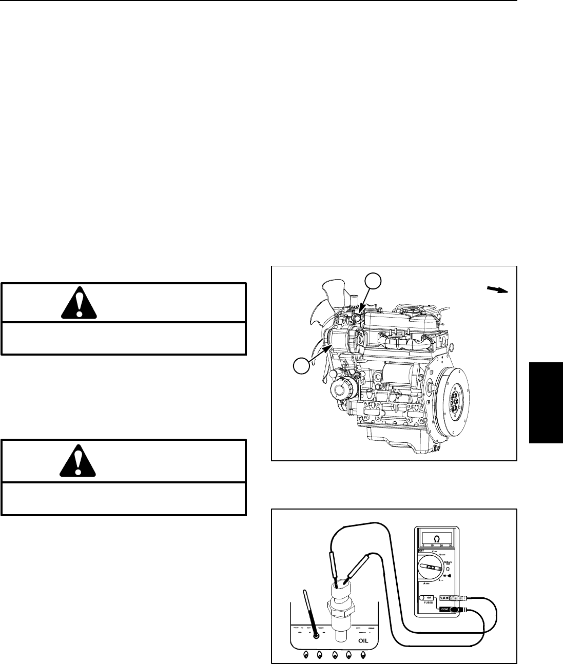
Reelmaster 5010- H Page 5 - 71 Electrical System
Temperature Sender
The temperature sender is located near the alternator
on the water flange attached to the engine cylinder head
(Fig. 72). The Toro Electronic Controller (TEC) monitors
the operation of the temperature sender.
The resistance of the temperature sender reduces as
the engine coolant temperature increases. The chang-
ing resistance of the temperature sender is used as an
analog input to the TEC controller to indicate engine
coolant temperature during machine operation.
Temperature Sender Test
1. Park the machine on a level surface, engage the
parking brake, lower the cutting units and stop the en-
gine. Remove the key from the ignition switch. Open
hoodtogainaccesstoengine.
2. Locate temperature sender on engine and discon-
nect wire harness connector from sender.
CAUTION
Make sure engine is cool before removing the
temperature sender from engine.
3. Lower coolant level in the engine and remove the
temperature sender from water flange.
4. Put sender in a container of oil with a thermometer
and slowly heat the oil (Fig. 73).
CAUTION
Handle the hot oil with extreme care to prevent
personal injury or fire.
NOTE: Prior to taking resistance readings with a digital
multi meter, short the meter test leads together. The me-
ter will display a small resistance value (usually 0.5
ohms or less) due to the internal resistance of the meter
and test leads. Subtract this value from from the mea-
sured value of the component you are testing.
5. Check resistance of the sender with a multimeter
(ohms setting) as the oil temperature increases.
A. The meter should indicate from 11.4 to 13.6 ohms
at 68oF(20
oC).
B. The meter should indicate from 2.3 to 2.6 ohms at
140oF(60
oC).
C. The meter should indicate from 0.6 to 0.7 ohms at
212 oF(100
oC).
6. Replace temperature sender if specifications are not
met.
7. Install temperature sender to the water flange.
A. Clean threads of water flange and temperature
sender thoroughly. Apply thread sealant to the
threads of the sender.
B. Screw sender into the water flange until it is finger
tight. Then, tighten sender an additional 2 to 3 full
turns.
C. Connect wire harness connector to sender.
8. Fill engine cooling system. Close and secure hood.
Figure 72
1. Temperature sender 2. Alternator
2
1FRONT
Figure 73
Electrical
System
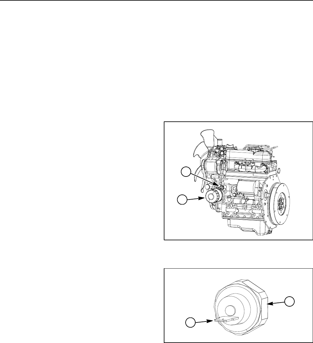
Reelmaster 5010- HPage 5 - 72Electrical System
Oil Pressure Switch
The engine oil pressure switch is a normally closed
switch that opens with pressure during normal engine
operation. The oil pressure switch is located on the en-
gine near the oil filter (Fig.74). The Toro Electronic Con-
troller (TEC) monitors the operation of the oil pressure
switch.
The oil pressure switch should open at approximately 8
PSI (0.56 kg/cm2).
If low engine oil pressure allows the oil pressure switch
to close during engine operation and the TEC controller
detects a low oil pressure input for ten (10) seconds, the
engine will be shut off by the controller. The operator will
see an advisory (advisory #169) on the InfoCenter dis-
play explaining that low engine oil pressure has caused
the engine shutdown.
NOTE: A faulty oil pressure switch or faulty wiring to the
oil pressure switch could cause a closed circuit that
would lead to engine shutdown with an InfoCenter dis-
play identifying Advisory #169.
Testing
1. Park the machine on a level surface, engage the
parking brake, lower the cutting units and stop the en-
gine. Remove the key from the ignition switch.
2. Raise and support hood. Locate oil pressure switch
on engine and disconnect the wire harness connector
from the switch.
3. Use a digital multimeter to measure continuity be-
tween the oil pressure switch terminal and the switch
base (ground connection) (Fig. 75).
A. With the engine not running, the oil pressure
switch should be closed so there should be continu-
ity between the switch terminal and the switch base
(0 ohms).
B. With the engine running, the oil pressure switch
should be open so there should not be continuity
between the switch terminal and the switch base (in-
finite ohms).
4. Replace the oil pressure switch if testing determines
that the switch is defective.
5. If testing of oil pressure switch determines that
switch operation is normal and the InfoCenter display is
identifying low engine oil as the cause of engine shut-
down, check for faulty wire in the oil pressure switch cir-
cuit.
6. After testing is completed, connect the wire harness
connector to the oil pressure switch. Lower and secure
hood.
NOTE: Refer to Kubota Workshop Manual, Diesel En-
gine, 05- E4B Series for information regarding engine
lubrication system and testing.
Figure 74
1. Oil pressure switch 2. Oil filter
2
1
1. Switch terminal 2. Switch base
Figure 75
2
1
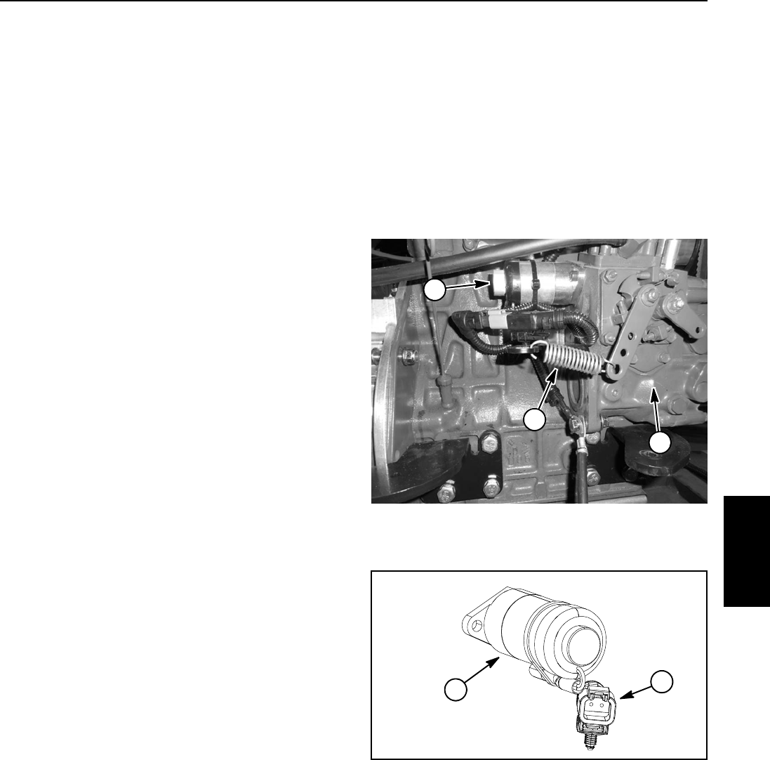
Reelmaster 5010- H Page 5 - 73 Electrical System
Fuel Actuator
The fuel actuator used on your Reelmaster must be en-
ergized by the TEC controller for the diesel engine to
run. The actuator is mounted to the injection pump on
theengine(Fig.76).
The fuel actuator and TEC controller work together to
maintain engine speed by adjusting the fuel delivery to
the engine. A sensor in the motor/generator provides
the generator/engine speed to the TEC controller via the
CAN- bus. If there is a change in engine speed (e.g. load
conditions change, engine speed switch pressed by op-
erator), the TEC controller modifies the electrical output
to the actuator which adjusts fuel as required to maintain
engine speed.
The TEC controller monitors the operation of the fuel ac-
tuator. If the TEC controller detected a fuel actuator
problem during engine operation, the InfoCenter Dis-
play can be used to identify the fault (see Fault Codes
in the Troubleshooting section in this chapter).
NOTE: If a problem with the fuel actuator or circuit
wiring exists, the extension spring attached to the actua-
tor bracket and engine speed control lever will cause the
engine to run at high idle (3150 RPM) with the engine
mechanical governor maintaining engine speed. In this
situation, the control arm mounted engine speed switch
will not change engine speed and a fault code should be
displayed on the InfoCenter Display.
Testing
1. Park the machine on a level surface, engage the
parking brake, lower the cutting units and stop the en-
gine. Remove the key from the ignition switch. Open
hoodtogainaccesstoengine.
2. Locate fuel actuator and disconnect wire harness
connector from fuel actuator.
NOTE: The fuel actuator may be tested in place or
removed from the engine for testing.
3. If the actuator is removed from the engine, make
sure that the actuator plunger moves freely and is free
of dirt, debris and corrosion.
NOTE: Prior to taking small resistance readings with a
digital multimeter, short the test leads together. The me-
ter will display a small resistance value (usually 0.5
ohms or less). This resistance is due to the internal re-
sistance of the meter and test leads. Subtract this value
from the measured value of the component you are test-
ing.
4. Using a multimeter (ohms setting), measure resis-
tance between the two terminals in the fuel actuator con-
nector. Resistance should be from 5.0 to 5.5 ohms.
5. If actuator coil resistance is incorrect, replace fuel
actuator.
6. When testing is complete, connect wire harness con-
nector to the fuel actuator.
7. Lower and secure hood.
1. Injection pump
2. Fuel actuator
3. Extension spring
Figure 76
1
2
3
1. Fuel actuator 2. Actuator connector
Figure 77
12
Electrical
System
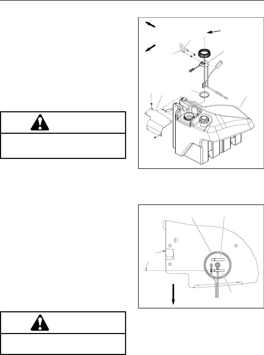
Reelmaster 5010- HPage 5 - 74Electrical System
Fuel Sender
The fuel sender is a variable resistance device that al-
lows the InfoCenter display to show level of the fuel tank.
The fuel sender is located in the fuel tank (Fig. 78).
Testing
1. Park the machine on a level surface, engage the
parking brake, lower the cutting units and stop the en-
gine. Remove the key from the ignition switch.
2. Remove screws that secure sender cover to fuel
tank. Lift cover from tank.
3. Disconnect the wire harness connector from the fuel
sender.
CAUTION
When testing circuit wiring and fuel sender,
make sure wire connections are secure before
turning ignition switch to ON to prevent an explo-
sion or fire from sparks.
4. To test the circuit wiring and InfoCenter fuel gauge,
use a jumper wire to connect the two (2) terminals in the
wire harness connector. Make sure that jumper wire
connections are secure. Turn the ignition switch to the
ON/PREHEAT position. InfoCenter display should indi-
cate a full fuel tank if circuit wiring and InfoCenter are
working correctly. Turn ignition switch OFF and continue
testing fuel sender if circuit wiring and InfoCenter are ac-
ceptable.
5. Loosen hose clamps and carefully disconnect sup-
ply and return fuel hoses from fittings on the top of the
fuel sender.
IMPORTANT: Before removing fuel sender from
tank, note orientation of fuel sender fittings for as-
sembly purposes (Fig. 79).
6. Carefully remove fuel sender cap that secures the fu-
el sender in the fuel tank.
7. Raise fuel sender and gasket from the fuel tank.
Clean all fuel from the sender.
CAUTION
Make sure fuel sender is completely dry (no fuel
on it) before testing. Perform test away from the
tank to prevent an explosion or fire from sparks.
Figure 78
1. Fuel gauge sender
2. Fuel sender cap
3. Gasket
4. Fuel supply hose
5. Fuel return hose
6. Fuel tank
7. Screw (5 used)
8. Sender cover
175 to 200 in- lb
(20to22N-m)
1
2
36
4
5
78
FRONT
RIGHT
Figure 79
1. Fuel sender
2. Fuel supply fitting
3. Fuel return fitting
3
12
90o
FRONT
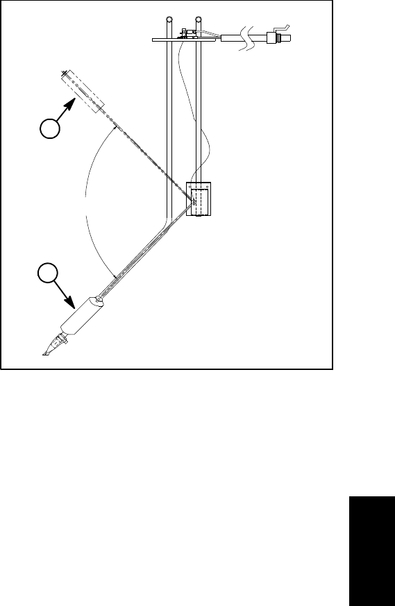
Reelmaster 5010- H Page 5 - 75 Electrical System
8. Use a multimeter to check resistance of the fuel
sender across the two (2) sender terminals (Fig. 80).
A. Resistance with the float in the full position (com-
pletely up) should be from 5 to 8 ohms.
B. Resistance with the float in the empty position
(completely down) should be from 89 to 95 ohms.
9. Replace fuel sender if testing determines that it is
faulty.
10.After testing, install sender into fuel tank and secure
with gasket and fuel sender cap. Make sure that fuel fit-
tings on sender are orientated at 90ofrom right side of
tank as shown in Figure 79. Also, to prevent damage to
fuel sender during assembly, make sure that fuel sender
does not turn as sender cap is tightened.
11.Install fuel hoses to fittings on sender and secure
with hose clamps. Connect fuel sender connector to
wire harness.
12.Secure sender cover to fuel tank with removed
screws. Figure 80
1. Sender full position 2. Sender empty position
1
2
90o
Electrical
System
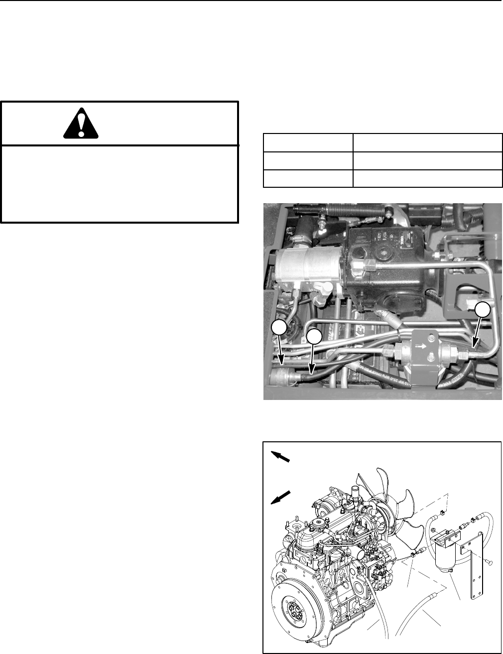
Reelmaster 5010- HPage 5 - 76Electrical System
Fuel Pump
The Reelmaster electric fuel pump is attached to the in-
side of the left side frame rail near the fuel tank (Fig. 81).
IMPORTANT: When testing fuel pump, make sure
that pump is not operated without fuel.
DANGER
Because diesel fuel is flammable, use caution
when handling it. Do not smoke while testing the
fuel pump. Do not test fuel pump while engine is
hot. Make sure that there is adequate ventilation
when testing. Always wipe up any spilled fuel be-
fore starting the engine.
Fuel Pump Capacity Test
1. Park the machine on a level surface, engage the
parking brake, lower the cutting units and stop the en-
gine. Remove the key from the ignition switch. Raise op-
erator seat and hood.
2. Disconnect wire harness electrical connector from
the engine fuel actuator to prevent the engine from start-
ing (see Fuel Actuator in this section).
3. Disconnect fuel hose (pump discharge) from the
fuel/water separator inlet fitting (Fig. 82).
4. Make sure fuel hoses attached to the fuel pump, fuel
filter and fuel tank suction tube screen are free of ob-
structions.
5. Place disconnected hose into a large, graduated cyl-
inder large enough to collect 1 quart (0.95 liter).
IMPORTANT: When testing the fuel pump, DO NOT
turn ignition switch to START.
6. Collect fuel in the graduated cylinder by turning igni-
tion switch to the ON/PREHEAT position. Allow pump to
run for fifteen (15) seconds, then return ignition switch
to OFF.
7. The amount of fuel collected in the graduated cylin-
der should be approximately 16 fl oz (475 ml) after fif-
teen (15) seconds.
8. Replace fuel pump if testing proves it to be faulty.
9. When testing is complete, install fuel hose to the fuel/
water separator. Make sure to secure fuel hose with
hose clamp.
10.Connect wire harness electrical connector to the en-
gine fuel actuator.
11. Bleed the fuel system.
12.Lower and secure operator seat and hood.
Fuel Pump Specifications
Pump Capacity 64 fl oz/min (1.9 liters/min)
Pressure 7PSI(48.3kPa)
Current Draw 2.0 amp
Figure 81
1. Fuel pump 2. Pump discharge hose
12
2
Figure 82
1. Fuel hose (from pump)
2. Hose clamp
3. Fuel/water separator
4. Fuel return hose
FRONT
RIGHT
2
3
1
4
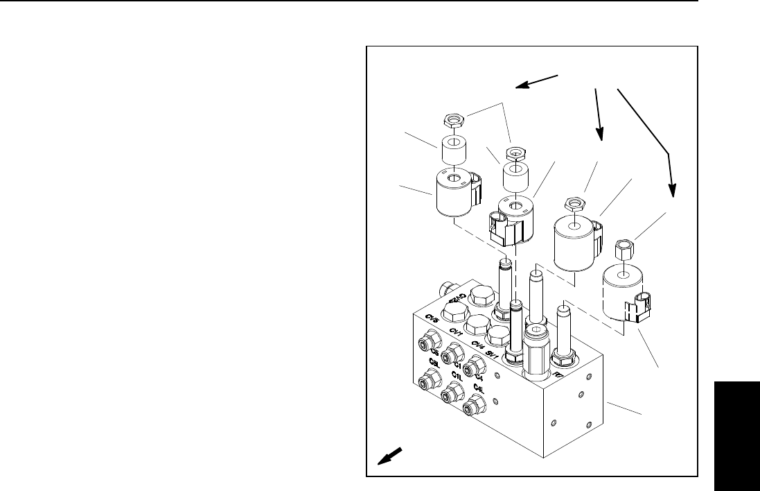
Reelmaster 5010- H Page 5 - 77 Electrical System
Service and Repairs
NOTE: See the Kubota Workshop Manual, Diesel En-
gine, 05- E4B Series for engine electrical component re-
pair information.
Hydraulic Solenoid Valve Coils
A hydraulic solenoid valve coil on the lift control manifold
(Fig. 83) can be replaced without opening the hydraulic
system.
Removal
1. Park machine on a level surface, lower cutting units,
stop engine and engage parking brake. Remove key
from ignition switch.
2. The lift control manifold is attached to a frame brack-
et under the operator floor plate. Access to the lift control
manifold can be obtained by removing the floor plate.
Refer to Figure 83 for solenoid coil locations on the lift
control manifold.
3. Disconnect the wire harness electrical connector
from the solenoid valve coil to be replaced.
4. Remove the nut from the hydraulic valve.
5. If equipped (SV1 and SV3 on lift control manifold), re-
move coil spacer from hydraulic valve.
6. Slide the solenoid coil from the valve.
7. Clean any corrosion or dirt from the valve.
Installation
1. Slide new coil assembly onto the hydraulic valve.
2. If equipped (SV1 and SV3 on lift control manifold),
slide coil spacer onto hydraulic valve.
3. Install the nut onto the valve and torque nut 60 in- lb
(6.7 N- m) (do not over tighten).
4. Connect the machine wire harness connector to the
solenoid coil.
1. Lift control manifold
2. Solenoid coil SVRV
3. Nut
4. Solenoid coil SV2
5. Nut
6. Solenoid coil SV1
7. Coil spacer
8. Solenoid coil SV3
Figure 83
1
2
3
4
5
5
6
7
7
8
FRONT
60 in- lb
(6.7 N- m)
Electrical
System
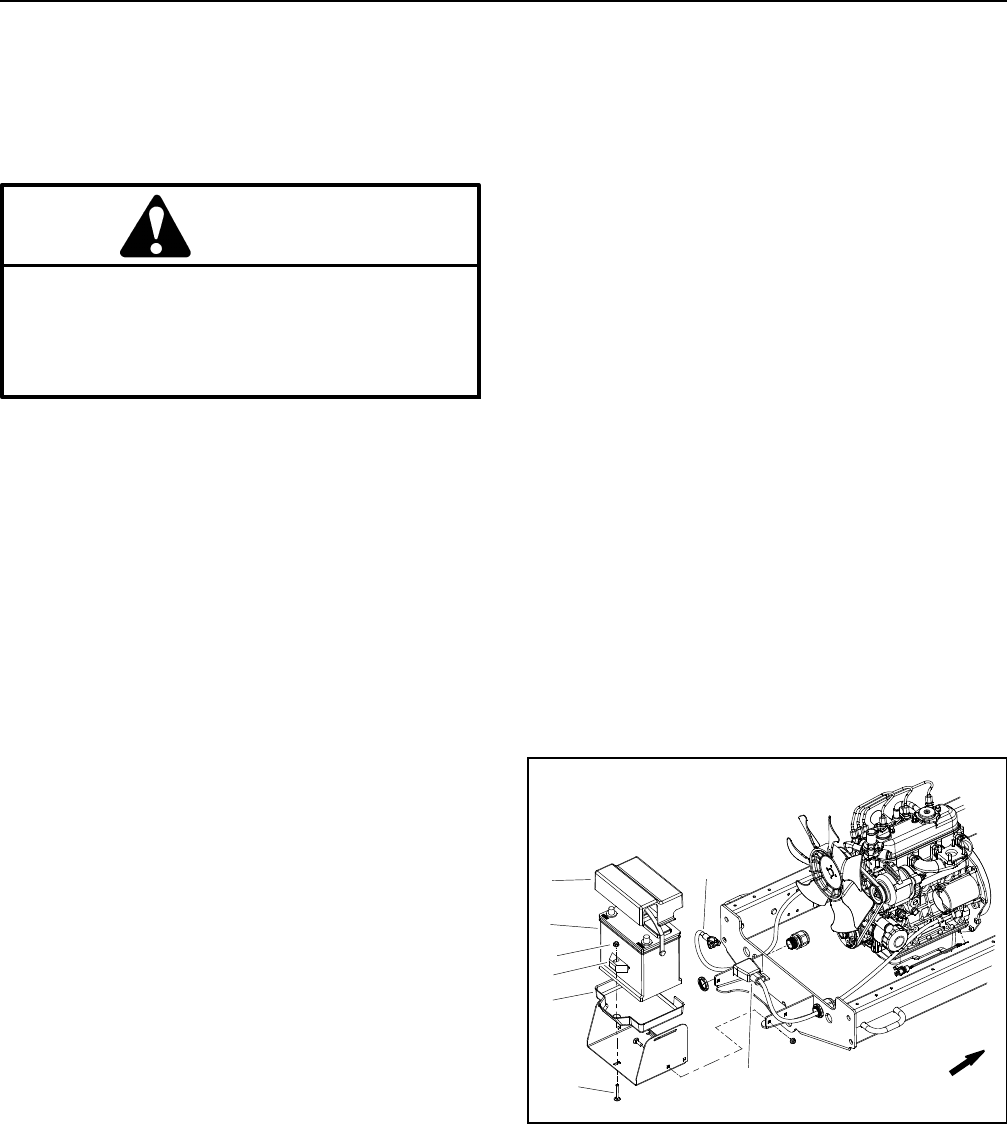
Reelmaster 5010- HPage 5 - 78Electrical System
12 VDC Battery Service
The battery is the heart of the 12 VDC electrical system.
With regular and proper service, battery life can be ex-
tended. Additionally, battery and electrical component
failure can be prevented.
CAUTION
When working with batteries, use extreme cau-
tion to avoid splashing or spilling electrolyte.
Electrolyte can destroy clothing and burn skin or
eyes. Always wear safety goggles and a face
shield when working with batteries.
Battery Specifications
BCI Group Size 55
585 CCA at 0oF(-18
oC)
95 minutes reserve capacity at 80oF(27
oC)
Electrolyte Specific Gravity
Fully charged: 1.265 corrected to 80oF(27
oC)
Discharged: less than 1.240
Removal and Installation (Fig. 84)
1. Park machine on level surface, lower cutting units,
stop engine, apply parking brake and remove key from
ignition switch.
2. Open screen at rear of machine and remove battery
cover to access battery.
3. Loosen and remove negative cable from battery. Af-
ter negative cable is removed, loosen and remove posi-
tive cable.
4. Loosen flange nut that secures battery retainer.
5. Carefully remove battery from machine.
6. Install battery in reverse order making sure to con-
nect and tighten positive cable to battery before con-
necting negative cable.
NOTE: Before connecting the negative (ground) cable
to the battery, connect a digital multimeter (set to DC
Amps) between the negative battery post and the nega-
tive (ground) cable connector. The reading should be
less than 0.1 Amp. If the reading is 0.1 Amp or more, the
machine’s electrical system should be tested for short
circuits or faulty components and repaired.
7. Coat battery posts and cable connectors with Battery
Terminal Protector (Toro Part No. 107- 0392) or petro-
leum jelly to prevent corrosion.
8. Install battery cover. Close and secure screen.
Battery Inspection and Maintenance
1. Check battery for cracks. Replace battery if cracked
or leaking.
2. Check battery terminal posts for corrosion. Use wire
brush to clean corrosion from posts.
IMPORTANT: Before cleaning the battery, tape or
block vent holes to the filler caps and make sure the
caps are on tightly.
3. Check for signs of wetness or leakage on the top of
the battery which might indicate a loose or missing filler
cap, overcharging, loose terminal post or overfilling.
Also, check battery case for dirt and oil. Clean the bat-
tery with a solution of baking soda and water, then rinse
it with clean water.
4. Check that the cover seal is not broken away. Re-
place the battery if the seal is broken or leaking.
5. If the battery electrolyte is accessible, check the
electrolyte level in each cell. If the level is below the tops
of the plates in any cell, fill all cells with distilled water
between the minimum and maximum fill lines. Do not fill
cells above the fill line. Charge at 15 to 25 Amps for fif-
teen (15) minutes to allow sufficient mixing of the elec-
trolyte.
1. 12 VDC battery
2. Battery tray
3. Retainer
4. Flange nut
5. Carriage screw
6. Negative battery cable
7. Positive battery cable
8. Battery cover
Figure 84
FRONT
2
3
6
8
1
57
4
Reelmaster 5010- H Page 5 - 79 Electrical System
Battery Storage
If the machine will be stored for more than thirty (30)
days:
1. Charge battery fully before storing the machine (see
Battery Service in this section).
2. Either remove battery from machine and store on a
shelf or leave battery on the machine. If the battery is
stored on the machine, leave battery cables disconnect-
ed.
3. Store battery in a cool atmosphere to avoid quick de-
terioration of the battery charge.
4. To help prevent the battery from freezing during stor-
age, make sure it is fully charged (see Battery Service
in this section).
Battery Testing
1. Perform a high- discharge test with an adjustable
load tester. This is one of the most reliable means of test-
ing a battery as it simulates the cold- cranking test. A
commercial battery load tester is required to perform
this test.
CAUTION
Follow the manufacturer’s instructions when us-
ing a battery load tester.
A. Check the voltage across the battery terminals
prior to testing the battery. If the voltage is less than
12.4 VDC, charge the battery before performing a
load test.
B. If the battery has recently been charged, use a
battery load tester following the manufacturer’s in-
structions to apply a 150 Amp load for fifteen (15)
seconds. This step will remove the surface charge.
C. Make sure battery terminals are free of corrosion.
D. Estimate the internal temperature of the battery
to the nearest 10 degrees F.
E. Connect a battery load tester to the battery termi-
nals following the manufacturer’s instructions. Con-
nect a digital multimeter to the battery terminals.
F. Apply a test load of 270 Amps (one half the crank-
ing performance rating of the battery) to the battery
for fifteen (15) seconds.
G. Take a battery voltage reading at fifteen (15) se-
conds, then remove the load.
H. Using the table in the column to the right, deter-
mine the minimum voltage for the battery tempera-
ture reading. If the test voltage is below the minimum
voltage for the battery temperature, replace the bat-
tery. If the test voltage is at or above the minimum,
return the battery to service.
Minimum
Voltage
Battery
Temperature
9.6 70oF (and up) 21oC(andup)
9.5 60oF16oC
9.4 50oF10oC
9.3 40oF 4oC
9.1 30oF-1
oC
8.9 20oF-7
oC
8.7 10oF-12
oC
8.5 0oF-18
oC
2. If the battery electrolyte is accessible, the specific
gravity of the electrolyte can be used to determine the
battery condition.
IMPORTANT: Make sure the area around the cells is
clean before opening the battery caps.
A. Measure the specific gravity of each cell with a
hydrometer. Draw electrolyte in and out of the
hydrometer barrel prior to taking a reading to warm-
upthehydrometer.Atthesametimetakethetem-
perature of the cell.
B. Temperature correct each cell reading. For each
10oF(5.5
oC) above 80oF (26.7oC) add 0.004 to the
specific gravity reading. For each 10oF(5.5
oC) be-
low 80oF (26.7oC) subtract 0.004 from the specific
gravity reading.
Example: Cell Temperature 100oF
Cell Gravity 1.245
100oF minus 80oF equals 20oF
(37.7oC minus 26.7oC equals 11.0oC)
20oF multiply by 0.004/10oF equals 0.008
(11oC multiply by 0.004/5.5oC equals 0.008)
ADD (conversion above) 0.008
Correctionto80
oF(26.7oC) 1.253
C. If the difference between the highest and lowest
cell specific gravity is 0.050 or greater or the lowest
cell specific gravity is less than 1.225, charge the bat-
tery. Charge at the recommended rate and time giv-
en in Battery Charging or until all cells specific
gravity is 1.225 or greater with the difference in spe-
cific gravity between the highest and lowest cell less
than 0.050. If these charging conditions can not be
met, replace the battery.
Electrical
System
Reelmaster 5010- HPage 5 - 80Electrical System
Battery Charging
To minimize possible damage to the battery and allow
the battery to be fully charged, the slow charging meth-
od is presented here. This charging method can be ac-
complished with a constant current battery charger
which is readily available.
CAUTION
Follow the manufacturer’s instructions when us-
ing a battery charger.
NOTE: Using specific gravity of the battery electrolyte
is the most accurate method of determining battery
condition.
1. Determine the battery charge level from either its
open circuit voltage or electrolyte specific gravity (if
electrolyte is accessible).
Battery Charge
Level
Open Circuit
Voltage
Specific
Gravity
100% 12.6 1.265
75% 12.4 1.225
50% 12.2 1.190
25% 12.0 1.155
0% 11.8 1.120
2. Determine the charging time and rate using the bat-
tery charger manufacturer’s instructions or the following
table.
Battery
Reserve
Capacity
(Minutes)
Battery Charge Level
(Percent of Fully Charged)
75% 50% 25% 0%
80 or less 3.8 hrs
@
3Amps
7.5 hrs
@
3Amps
11.3 hrs
@
3Amps
15 hrs
@
3Amps
81 to 125 5.3 hrs
@
4Amps
10.5 hrs
@
4Amps
15.8 hrs
@
4Amps
21 hrs
@
4Amps
126 to
170
5.5 hrs
@
5Amps
11 hrs
@
5Amps
16.5 hrs
@
5Amps
22 hrs
@
5Amps
171 to
250
5.8 hrs
@
6Amps
11.5 hrs
@
6Amps
17.3 hrs
@
6Amps
23 hrs
@
6Amps
above
250
6hrs
@10
Amps
12 hrs
@10
Amps
18 hrs
@10
Amps
24 hrs
@10
Amps
CAUTION
Do not charge a frozen battery because it can ex-
plode and cause injury. Let the battery warm to
60oF(16
oC) before connecting to a charger.
Charge the battery in a well- ventilated place to
dissipate gases produced from charging. These
gases are explosive; keep open flame and elec-
trical spark away from the battery. Do not smoke.
Nausea may result if the gases are inhaled. Un-
plug the charger from the electrical outlet before
connecting or disconnecting the charger leads
from the battery posts.
3. Following the battery charger manufacturer’s
instructions, connect the charger cables to the battery.
Make sure a good connection is made.
4. Charge the battery following the battery charger
manufacturer’s instructions.
5. While charging, occasionally check the battery. If the
electrolyte is violently gassing or spewing or if the bat-
tery case feels hot to the touch, the charging rate must
be lowered or temporarily stopped.
6. Determine if battery is fully charged before removing
battery from charger. Either of the following procedures
canbeused:
A. Continue charging and reduce charging rate as
needed until a two (2) hour period results in no in-
crease in voltage. Open circuit voltage should be ap-
proximately 12.6 volts for a fully charged battery.
B. If the battery electrolyte is accessible, three (3)
hours prior to the end of the charging, measure the
specific gravity of a battery cell once per hour. The
battery is fully charged when the cells are gassing
freely at a low charging rate and there is less than a
0.003 change in specific gravity for three (3) consec-
utive readings.

Reelmaster 5010- H Page 5 - 81 Electrical System
This page is intentionally blank.
Electrical
System
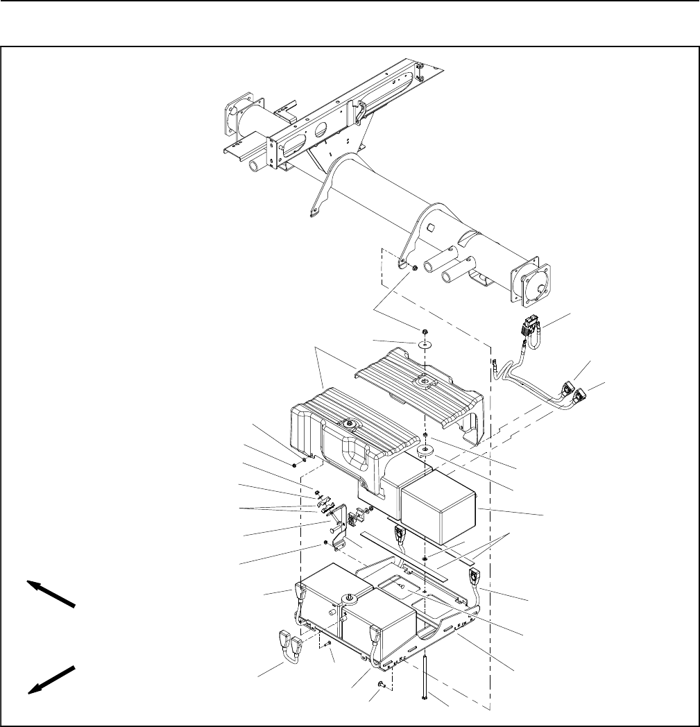
Reelmaster 5010- HPage 5 - 82Electrical System
48 VDC Battery Pack Service (Cutting Reel and Motor/Generator Systems)
1. Battery (4 used)
2. Battery tray
3. Push nut (2 used)
4. Carriage screw (2 used)
5. Flange nut (6 used)
6. Carriage bolt (4 used)
7. Flange nut (2 used)
8. Battery cover (2 used)
9. Hex nut (2 used)
10. Flat washer (2 used)
11. Carriage screw (2 used)
12. Flat washer (2 used)
13. Battery disconnect connector
14. Negative battery cable
15. Battery cable (2 used)
16. Battery jumper cable
17. Foam strip (4 used)
18. Clamp (4 used)
19. Batteryholddown(2used)
20. Cable bracket
21. Carriage bolt (2 used)
22. Flat washer (4 used)
23. Flange nut (6 used)
24. Carriage screw (4 used)
25. Positive battery cable
Figure 85
FRONT
RIGHT
2
3
6
8
9
10
11
13
1
7
12
14
15
16
17
18
19
20
4
21
22
23
24
25
23
15
15
5
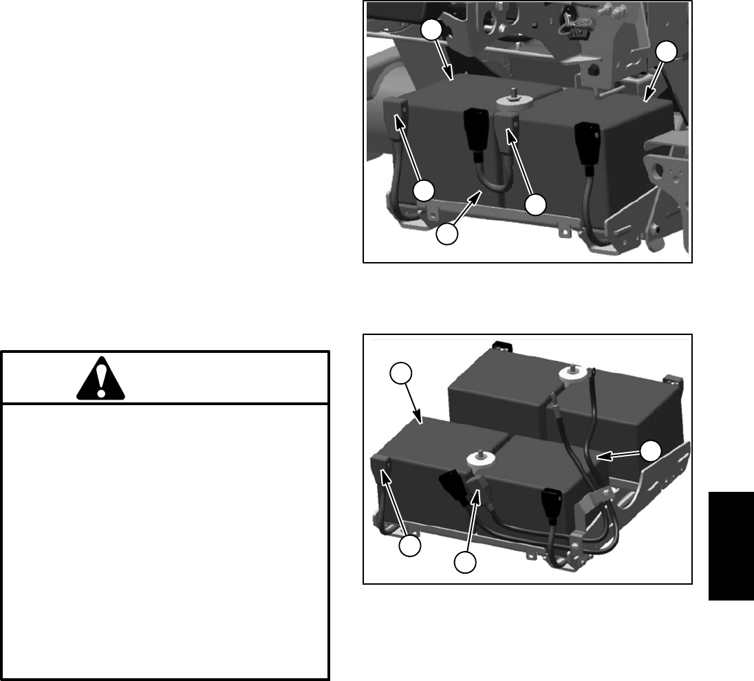
Reelmaster 5010- H Page 5 - 83 Electrical System
The 48 volt battery pack used in the Reelmaster 5010- H
electric reel drive system is composed of four (4) 12 volt
batteries that are connected in series. The batteries are
absorbed glass mat (AGM), valve regulated batteries
that are maintenance free with no provision for checking
or adjusting electrolyte level. The batteries are equipped
with a low pressure venting system designed to release
excess gas pressure and then automatically reseal. A
low self discharge rate prevents deterioration of battery
performance during non- use or storage.
Before performing any service on the batteries in the 48
VDC system, disconnect the 48 VDC system compo-
nents from the electrical power supply by separating the
48 VDC battery disconnect (see 48 VDC Battery Discon-
nect in the General Information section of this chapter).
This will prevent unexpected system operation.
Battery Specifications
Battery capacity 53 AH
650 CCA at 0oF(-18
oC)
WARNING
POTENTIAL HAZARD:
The battery terminals, metal tools and metal ve-
hicle parts could short together.
WHAT CAN HAPPEN:
Sparks can cause battery gasses to explode.
Damaged cables could short against metal ve-
hicle parts and cause sparks.
HOW TO AVOID THE HAZARD:
When removing or installing the batteries, do
not allow the battery terminals to short against
metal parts of the vehicle.
Do not allow metal tools or metal vehicle parts to
short between the battery terminals or battery
cables.
Always keep the battery retainers in place to
protect and secure the batteries.
48 VDC Battery Pack Removal (Fig. 85)
1. Park machine on level surface, lower cutting units,
stop engine, apply parking brake and remove key from
ignition switch.
2. Separate system components from the 48 VDC bat-
tery pack by unplugging the 48 VDC battery disconnect.
(see 48 VDC Battery Disconnect in the General Informa-
tion section of this chapter). This will prevent unex-
pected 48 VDC system component operation.
3. Remove battery covers to gain access to batteries.
1. RH front battery
2. LH front battery
3. Positive terminal
4. Jumper cable
Figure 86
1
2
3
3
4
1. LH rear battery
2. RH rear battery
3. Positive terminal
Figure 87
1
2
3
3
4. Carefully remove battery jumper cable (item 16) from
front batteries to open battery circuit. Do not allow tools
or vehicle components to complete the battery circuit
during cable removal.
5. Remove remaining cables from battery terminals.
Position battery cables away from battery terminals.
6. Remove hex nut and battery hold down that secure
batteries to battery tray.
7. Carefully remove batteries from battery tray and ma-
chine.
8. If battery cable removal is needed, note routing of ca-
bles for installation purposes before removing cables
from machine.
9. Inspect foam strips on battery tray. Replace strips if
damaged.
Electrical
System
Reelmaster 5010- HPage 5 - 84Electrical System
48 VDC Battery Pack Installation (Fig. 85)
1. Make sure that the 48 VDC battery disconnect is sep-
arated to prevent unexpected 48 VDC system compo-
nent operation (see 48 VDC Battery Disconnect in the
General Information section of this chapter).
2. Make sure the battery tray is clean and repainted if
necessary. Make sure battery cables, battery terminals
and all hold down fasteners are in good condition.
3. If battery cables were removed, install cables in posi-
tions noted during disassembly. If cables were removed
from rear batteries, make sure that cables are correctly
routed through clamps and secured with removed fas-
teners.
4. Place batteries onto battery tray in machine.
5. Secure each battery with battery hold down and hex
nut.
IMPORTANT: When connecting the battery pack in
the 48 volt system, make sure that battery polarity
is carefully checked. Damage to fuses or other sys-
tem components can occur if batteries are not con-
nected correctly.
6. Install all of the battery cables except the battery
jumper cable (item 16). Make sure that cables are con-
nected to correct battery terminal noting battery polarity
as shown in Figures 86 and 87. Torque nuts on battery
cable clamps from 50 to 70 in- lb (5.7 to 7.9 N- m).
7. Carefully install battery jumper cable (item 16) to
front batteries. Do not allow tools or vehicle components
to complete the battery circuit during cable installation.
Torque nuts on battery jumper cable clamps from 50 to
70 in- lb (5.7 to 7.9 N- m).
8. Apply Toro battery terminal protector (see Special
Tools in this chapter) to all battery posts and cable con-
nectors to reduce corrosion after cable connections are
made. Make sure that terminal boots are positioned
over all cable connections.
9. Install battery covers.
10.Plug the 48 VDC battery disconnect back into the
socket before operating the machine.
48 VDC Battery Pack Service
Clean the battery pack with clean water and a towel. Do
not use solvents or chemicals to clean the battery pack.
When testing batteries in the battery pack of your Reel-
master, it is important to test all four (4) individual batter-
ies. Proper performance of the machine depends on all
batteries being in good condition. Testing will determine
if one (or more) of the batteries needs to be replaced.
A simple battery test can be done using a multimeter to
perform a voltage test of each of the batteries in the bat-
tery pack. Measure the battery voltage with the multime-
ter and record battery voltage. The measured voltage
can be used to determine battery state of charge. If the
voltage of any of the batteries varies by more than 10%,
it indicates a problem with the battery that has the lower
voltage.
If the battery pack system voltage drops below 50 VDC
due to storage, age or malfunction, battery inspection
and/or charging may be necessary. The batteries
should be individually charged with a 12 VDC charger
rated for operation with absorbed glass mat (AGM),
valve regulated lead acid batteries. Charge the batteries
following the battery charger manufacturer’s instruc-
tions. Maximum charge voltage should be limited to 14.8
VDC. Operation of the machine will also charge the bat-
teriesinthe48VDCsystem.
A battery load tester can be used to test individual bat-
teries. Many locally available battery load testers do not,
however, have any adjustment on the load that is put on
the battery. Results received from using load testers
should follow the recommendations of the load tester
manufacturer.
48 VDC Battery Pack Storage
There are no special procedures or precautions for bat-
tery storage less than six (6) months. Batteries should
be disconnected from all potential load sources during
storage. Recommended storage temperatures should
be between 50oFand77
oF(10
oCto25
oC). Storage at
elevated temperatures will result in accelerated rates of
self discharge. Make sure that batteries are fully
charged prior to storage. If battery pack is stored in a dis-
charged state, battery performance and life will be di-
minished.
During storage, battery charging is recommended
whenever voltage of an individual battery drops below
12.7 VDC.

Reelmaster 5010- H Page 5 - 85 Electrical System
This page is intentionally blank.
Electrical
System
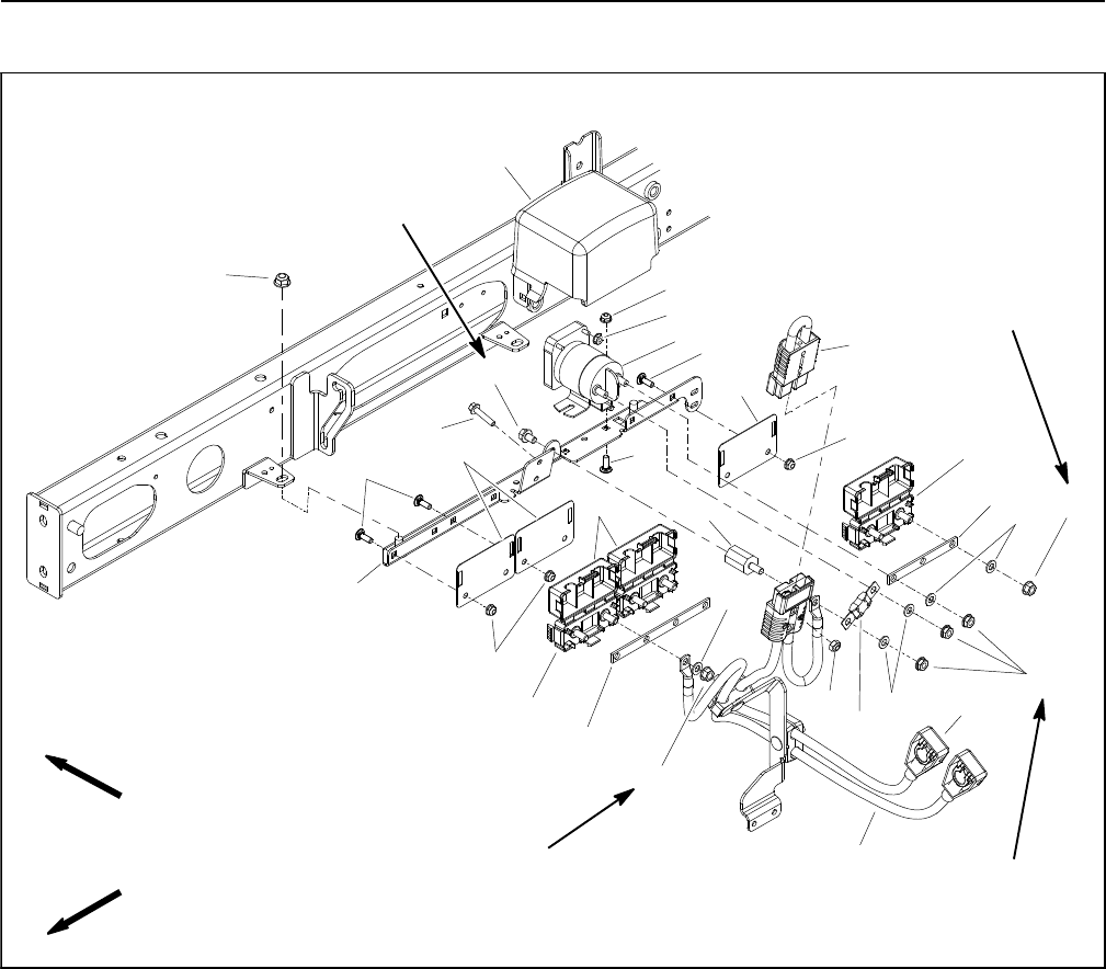
Reelmaster 5010- HPage 5 - 86Electrical System
48 VDC Electrical Power Connections
1. Bracket
2. Main contactor
3. Holder bracket (3 used)
4. Jumper strap holder (3 used)
5. Jumper strap (positive connections)
6. Isolator
7. Flange head screw
8. Flat washer (9 used)
9. Flange nut (3 used)
10. Nut (2 used)
11. Flange nut (6 used)
12. Contactor cover
13. Jumper strap (ground connections)
14. 250 amp fuse
15. Flange head screw (2 used)
16. 48 VDC battery disconnect
17. Lock nut (2 used)
18. Flange nut (2 used)
19. Carriage screw (8 used)
20. Flange nut (8 used)
21. Positive battery cable
22. Negative battery cable
Figure 88
FRONT
RIGHT
2
3
6
8
9
10
11
13
1
5
7
12
14
15
16
17
18
19
20
4
4
19
8
811
4
3
20
19
20
22
21
9to13ft-lb
(13to17N-m)
40 to 50 in- lb
(4.6 to 5.6 N- m)
40 to 50 in- lb
(4.6 to 5.6 N- m)
9to13ft-lb
(13 to 17 N- m)
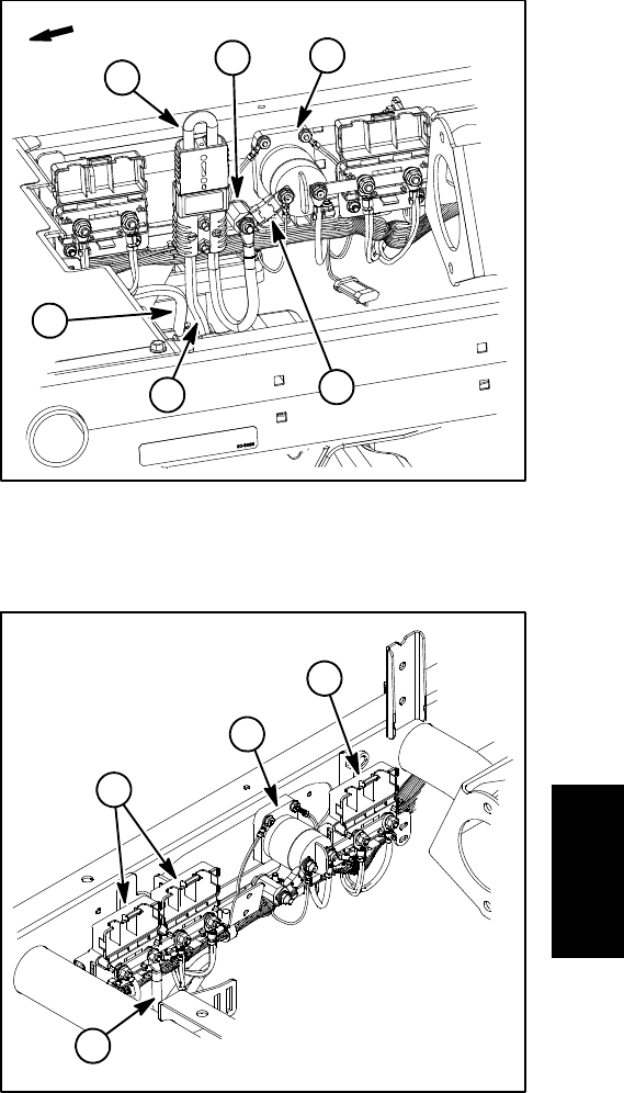
Reelmaster 5010- H Page 5 - 87 Electrical System
Disassembly
1. Park machine on level surface, lower cutting units,
stop engine, apply parking brake and remove key from
ignition switch.
2. Separate system components from the 48 VDC bat-
tery pack by unplugging the 48 VDC battery disconnect.
(see 48 VDC Battery Disconnect in the General Informa-
tion section of this chapter). This will prevent unex-
pected 48 VDC system component operation.
3. Raise and support operator seat to access 48 VDC
power connections. If front jumper strap holders for
ground (negative) connections are to be accessed, re-
move operator floor plate from frame.
4. Label all wire connector locations for assembly pur-
poses.
5. Disconnect electrical connections and remove com-
ponents as needed using Figures 88, 89 and 90 as
guides.
Assembly
1. Install all removed components and electrical con-
nections as needed using Figures 88, 89 and 90 as
guides. Use torque specifications identified in Figure 88
when installing fasteners.
2. Apply Toro battery terminal protector (see Special
Tools in this chapter) to all cable connectors to reduce
corrosion after cable connections are made. Make sure
that terminal boots and connection covers are posi-
tioned over all cable connections.
3. If operator floor plate was removed, secure floor
platetoframewithremovedfasteners.
4. Plug the 48 VDC battery disconnect back into the
socket when all electrical components have been in-
stalledtomachine.
5. Lower and secure operator seat.
Figure 89
1. Main contactor
2. Positive battery cable
3. 48V battery disconnect
4. Negative battery cable
5. Isolator
6. Fuse (250A / 58V)
FRONT
2
35
6
1
4
1. Main contactor
2. Positive connections
3. Ground connections
4. Neg battery cable
Figure 90
2
1
4
3
Electrical
System
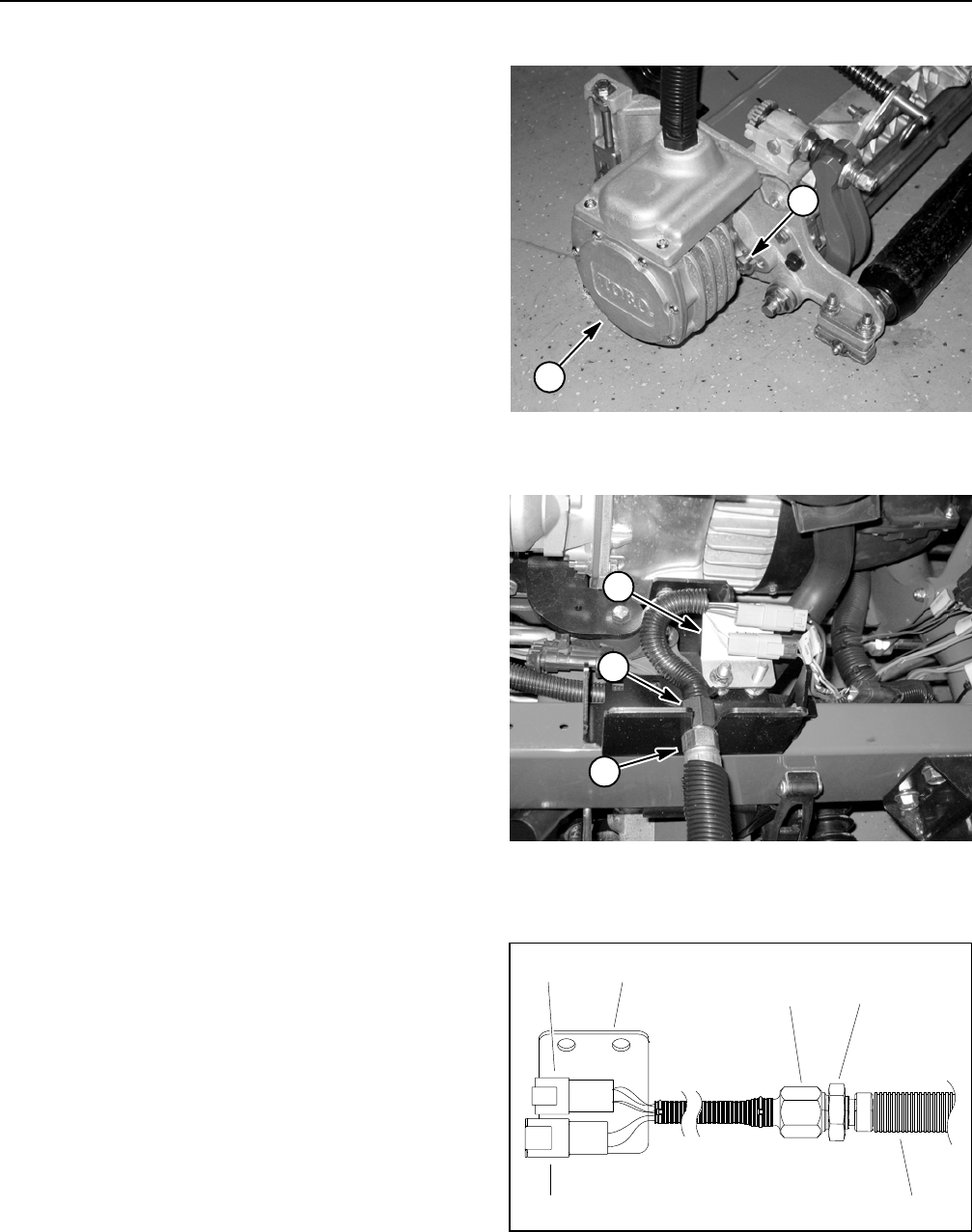
Reelmaster 5010- HPage 5 - 88Electrical System
Cutting Reel Motor
NOTE: If electrical problems exist with a cutting reel
motor, a fault may have occurred that would be indicated
by a fault code on the InfoCenter Display. Before consid-
ering that reel motor service work is necessary, check
for any existing fault codes that indicate problems with
a reel motor (see Fault Codes in the Troubleshooting
section of this chapter).
IMPORTANT: When performing service or mainte-
nance on the cutting reel motors, take care to not
damage the motors or electrical connections.
Removal
1. Park machine on level surface, lower cutting units,
stop engine, apply parking brake and remove key from
ignition switch.
2. Separate system components from the 48 VDC bat-
tery pack by unplugging the 48 VDC battery disconnect.
(see 48 VDC Battery Disconnect in the General Informa-
tion section of this chapter). This will prevent unex-
pected 48 VDC system component operation.
IMPORTANT: When removing cutting reel motor,
take care to not damage the cable. The cable is not
available as a replacement part.
3. Remove cutting reel motor from cutting unit (Fig. 91):
A. Loosen two (2) cap screws that secure the cutting
reel motor to the cutting unit side plate.
B. Rotate motor clockwise to disengage motor
flange from cap screws and remove motor from cut-
ting unit. Position and support reel motor away from
cutting unit.
4. Remove O- ring from flange of motor and discard
O- ring.
5. Inspect cutting reel threaded insert splines for wear.
Replace inserts if necessary (see Cutting Reel Assem-
bly in the Service and Repairs section of Chapter 7 Cut-
ting Units).
6. The cutting unit side plates have threaded inserts at
the locations used for the cap screws that secure the
reel motor. Check the condition of the threaded inserts
and replace inserts if damage is found. Inserts should be
torqued from 35 to 40 ft- lb (48 to 54 N- m) during instal-
lation.
7. Place protective plastic cap (see Special Tools in this
chapter) into the hole in the cutting unit side plate to pre-
vent debris entry into reel bearing area.
1. Cutting reel motor 2. Cap screw
Figure 91
1
2
1. Bulkhead nut
2. Bulkhead fitting
3. Connector plate
Figure 92
1
2
3
1. Cable from motor
2. Bulkhead nut
3. Bulkhead fitting
4. 4 wire connector
5. 2 wire connector
6. Connector plate
Figure 93
23
15
46
Reelmaster 5010- H Page 5 - 89 Electrical System
8. If cutting reel motor is to be removed from machine,
disconnect reel motor cable from machine wire harness
(Figs. 92 and 93):
A. Locate reel motor cable electrical connections at
machine wire harness for motor that is to be re-
moved.
B. Disconnect two (2) motor cable connectors from
machine wire harness.
C. Remove flange nut that secures reel motor cable
connector plate to machine frame and separate mo-
tor cable from machine.
D. Locate and loosen bulkhead nut that secures reel
motor cable to bulkhead bracket on machine. Sepa-
rate cable from bracket.
9. Remove cutting reel motor with attached cable from
machine.
Installation
NOTE: Refer to Figure 94 for correct placement of cut-
ting unit reel motors and weights.
1. Install new O- ring to flange of cutting unit motor.
Coat spline shaft of the reel motor with No. 2 multipur-
pose lithium base grease.
2. Remove protective plastic cap from the hole in the
cutting unit side plate.
3. Make sure that the two (2) cap screws for the cutting
reel motor are installed into the cutting unit side plate
with approximately 1/2 inch (12.7 mm) of threads ex-
posed on each screw.
4. Secure cutting reel motor to cutting unit (Fig. 91):
A. Rotate the motor clockwise so the motor flanges
clear the cap screws in the cutting unit side plates.
Align reel motor shaft splines with cutting reel insert
splines. Slide motor shaft into cutting reel threaded
insert. Make sure that cable is on the upper side of
the motor after installation.
B. Rotate the motor counterclockwise until the mo-
tor flanges are encircling the cap screws in the cut-
ting unit side plates. Tighten two (2) cap screws to
secure cutting reel motor to cutting unit.
5. If cutting reel motor was removed from machine,
connect reel motor cable to machine wire harness (Fig.
93):
A. Connect two (2) reel motor cable connectors to
machine wire harness.
B. Position reel motor cable connector plate to ma-
chine frame and secure with flange nut.
C. Position reel motor cable to bulkhead bracket on
machine and tighten bulkhead nut.
6. Lubricate grease fitting on cutting unit side plate that
includes reel motor.
7. After completing installation of all cutting unit motors,
plug the 48 VDC battery disconnect back into the socket.
1. Reel motor location 2. Weight location
Figure 94
FRONT
4 1 5
32
12
Electrical
System
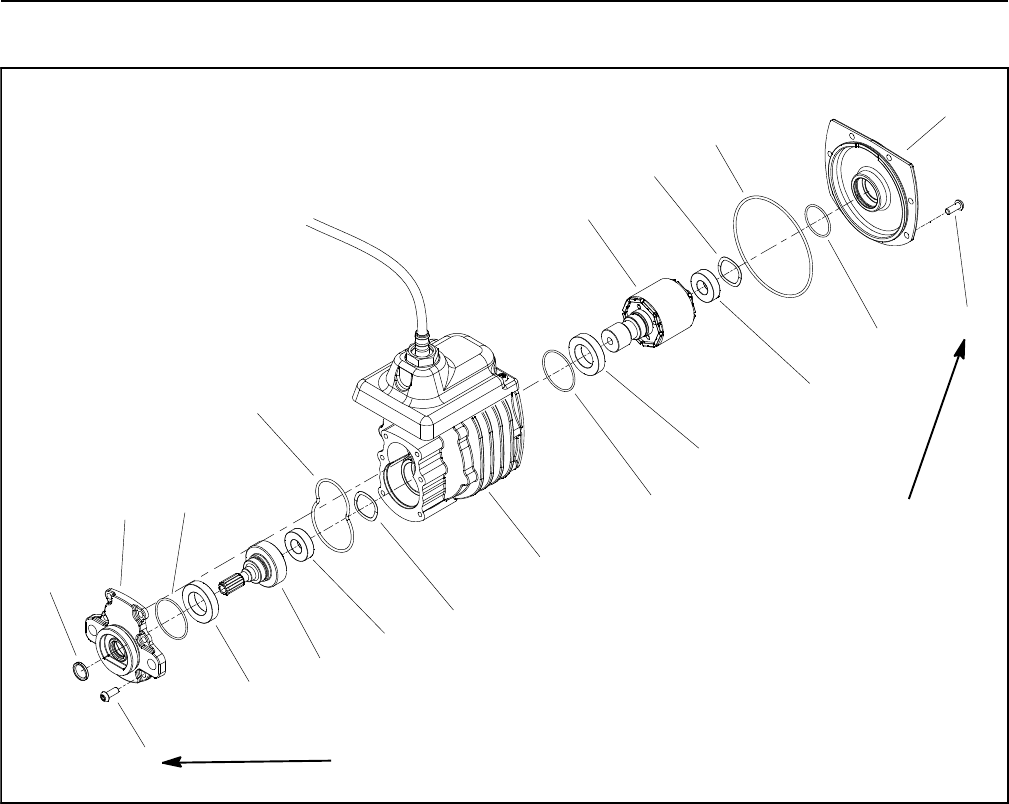
Reelmaster 5010- HPage 5 - 90Electrical System
Cutting Reel Motor Service
1. Torx head screw (12 used)
2. Motor cover
3. O- ring
4. Wave washer (2 used)
5. Bearing (2 used)
6. Rotor
7. Bearing (2 used)
8. O- ring (2 used)
9. Housing/controller/cable assembly
10. O- ring
11. Output gear
12. Gearbox cover
13. Shaft seal
14. O- ring
Figure 95
5
7
7
5
6
11
8
1
4
3
10
8
9
12
14
13
2
4
1
70 to 80 in- lb
(8 to 9 N- m)
70 to 80 in- lb
(8 to 9 N- m)
NOTE: If motor housing, controller or cable damage oc-
curs, cutting reel motor replacement is necessary.
These components are not available separately.
IMPORTANT: When working on the cutting reel mo-
tor, use a clean work space with a non- metal sur-
face. The reel motor rotor includes very powerful
magnets that can cause the rotor to move unexpect-
edly if working on a metal surface. Also, any metallic
debris that gets attracted to the rotor can damage
the motor after assembly.
Disassembly (Fig. 95)
1. Remove six (6) torx head screws that secure gear-
box cover (item 12) to front of motor housing.
2. Carefully slide gearbox cover from front of motor.
3. Remove and discard O- rings (items 8 and 10) from
gearbox cover.
4. Slide output gear assembly (items 5, 11 and 7) from
motor housing. Remove wave washer (item 4).
5. Remove six (6) torx head screws that secure motor
cover (item 2) to rear of motor housing. Leave cover on
rotor shaft.
IMPORTANT: The rotor magnets are very powerful
and can cause the rotor to shift position very rapidly
during removal. Use cutting reel motor rotor tool set
(see Special Tools in this chapter) to remove rotor.
Be cautious during rotor removal to prevent compo-
nent damage or personal injury.
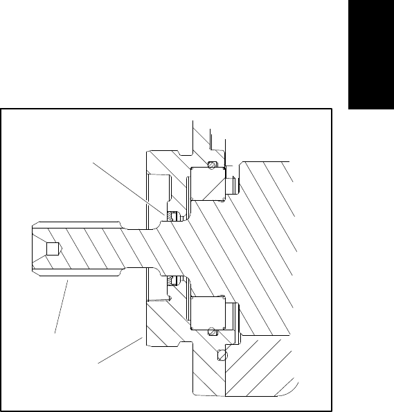
Reelmaster 5010- H Page 5 - 91 Electrical System
6. Use cutting reel motor rotor tool set (see Special
Tools in this chapter) to carefully remove rotor assembly
(items 5, 6 and 7) and motor cover (item 2) from motor
housing.
7. Remove motor cover and wave washer (item 4) from
rotor assembly. Remove and discard O- rings (items 14
and 3) from cover.
8. Remove and discard O- ring (item 8) from motor
housing.
IMPORTANT: Make sure to not damage the gearbox
cover counter bore when removing the shaft seal
from the cover.
9. Carefully remove shaft seal from gearbox cover. Dis-
card removed seal.
10.If necessary, remove bearings from output gear
(item 11) and rotor (item 6). Discard bearings if removed.
11.Inspect grease in output gear area of motor housing.
If grease is clean and not contaminated, it can remain in
housing. If grease is contaminated, clean grease from
housing and replace with 15 ml of NLGI grade 00 grease
during motor assembly.
12.Inspect cutting reel motor components for wear or
damage. Replace components or cutting unit motor as-
sembly if necessary.
Assembly (Fig. 95)
1. Make sure that motor components are cleaned be-
fore assembly.
2. If bearings were removed from output gear (item 11)
or rotor (item 6) install new bearings. Make sure that
bearings are fully pressed onto shafts.
3. Lubricate new inner O- ring (item 8) with dielectric lu-
bricant (see Special Tools in this chapter) and install O-
ring into groove in motor housing.
IMPORTANT: The rotor magnets are very powerful
and can cause the rotor to shift position very rapidly
during installation. Use cutting reel motor rotor tool
set (see Special Tools in this chapter) to remove ro-
tor. Be cautious during rotor installation to prevent
component damage or personal injury.
4. Use cutting reel motor rotor tool set (see Special
Tools in this chapter) to carefully install rotor assembly
(items 5, 6 and 7) into motor housing.
5. Lubricate new O- rings (items 14 and 3) with dielec-
tric lubricant (see Special Tools in this chapter) and
install O- rings to grooves in motor cover. Place wave
washer (item 4) in cover.
6. Carefully slide motor cover onto rotor until it contacts
motor housing. Secure cover with six (6) torx head
screws.
7. Make sure that rotor rotates without binding before
continuing with motor assembly.
8. Place wave washer (item 4) into housing bore for out-
put gear bearing.
9. Make sure that output gear area of motor housing
has clean grease remaining in housing. If grease was
cleaned from housing, install 15 ml of new NLGI grade
00 grease into housing during motor assembly.
10.Slide output gear assembly (items 5, 11 and 7) into
front of housing. Make sure that output gear teeth mesh
with rotor gear.
11. Install shaft seal (item 13) into gearbox cover. Press
shaft seal into front cover until it is flush with the cover
surface. Shaft seal should have the seal lip toward the
inside of the motor (Fig. 96).
12.Lubricate new O- rings (items 8 and 10) with dielec-
tric lubricant (see Special Tools in this chapter) and
install O- rings to grooves in gearbox cover.
IMPORTANT: Make sure to not damage the shaft
seal when installing the gearbox cover.
13.Carefully slide gearbox cover onto output gear shaft
until it contacts motor housing. Secure cover with six (6)
torx head screws.
14.Torque all torx screws (item 1) on gearbox cover and
motor cover from 70to80in-lb(8to9N-m).
1. Output gear
2. Gearbox cover
3. Shaft seal
Figure 96
3
2
1
Electrical
System
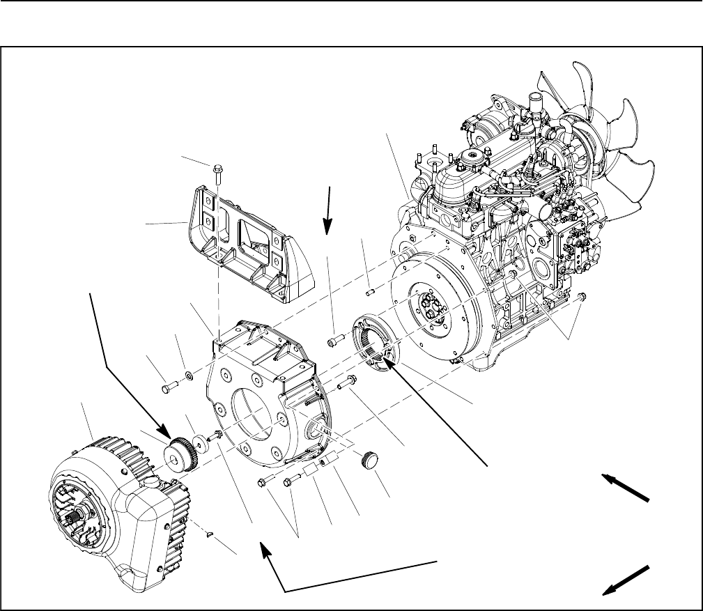
Reelmaster 5010- HPage 5 - 92Electrical System
Motor/Generator Assembly
Figure 97
1. Diesel engine
2. Motor/generator assembly
3. Flange head screw
4. Collar
5. Coupler hub
6. Woodruff key
7. Engine bellhousing
8. Cap screw (2 used)
9. Flat washer (2 used)
10. Flange head screw (7 used)
11. Flange nut (2 used)
12. R- clamp (for generator wire harness)
13. Clamp (for fuel return hose)
14. Caplug
15. Flange head screw (6 used)
16. Dowel pin (2 used)
17. Coupler flange
18. Socket head screw (3 used)
19. Muffler bracket
20. Flange head screw (4 used)
3
9
10
11
5
4
13
2
6
8
1
7
12
14
15
16
17
18
19
20
FRONT
RIGHT
50 to 60 ft- lb
(68to81N-m)
25 to 31 ft- lb
(34to42N-m)
Antiseize
Lubricant
Antiseize
Lubricant
NOTE: If electrical problems exist with the motor/gen-
erator assembly, a fault should have occurred that would
be indicated by a fault code on the InfoCenter Display.
Before considering that motor/generator service work is
necessary, check for any existing fault codes that indi-
cate problems with the motor/generator (see Fault
Codes in the Troubleshooting section of this chapter).
NOTE: The 48 VDC motor/generator is secured to the
engine bellhousing with six (6) flange head screws. Ac-
cess to these screws requires the bellhousing and mo-
tor/generator to be removed from the engine as an
assembly before removing the motor/generator from the
bellhousing.
Removal (Fig. 97)
1. Park machine on a level surface, lower cutting units,
stop engine, apply parking brake and remove key from
ignition switch.
2. Separate system components from the 48 VDC bat-
tery pack by unplugging the 48 VDC battery disconnect.
(see 48 VDC Battery Disconnect in the General Informa-
tion section of this chapter). This will prevent unex-
pected 48 VDC system component operation.
3. Raise and support hood and operator seat.
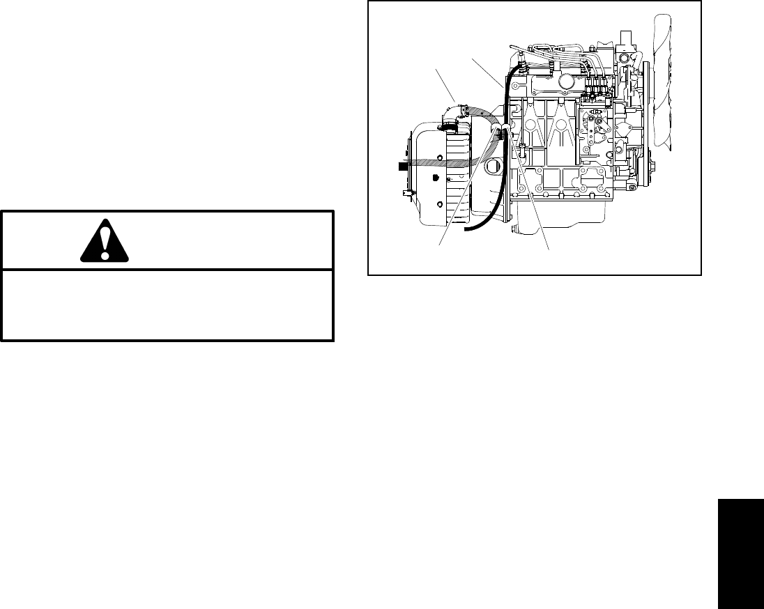
Reelmaster 5010- H Page 5 - 93 Electrical System
4. Disconnect hydraulic pump drive shaft from 48 VDC
motor/generator output shaft (see Hydraulic Pump
Drive Shaft in the Service and Repairs section of Chap-
ter 4 - Hydraulic System). Position drive shaft away from
engine.
5. Remove exhaust muffler from machine (see Exhaust
System in the Service and Repairs section of Chapter 3
- Kubota Diesel Engine).
6. Disconnect wire harness connector from motor/gen-
erator assembly.
CAUTION
Support motor/generator and bellhousing as-
sembly when removing it to prevent it from fal-
ling and causing personal injury. Assembly
weighs approximately 69 pounds (31 kg).
7. For assembly purposes, note locations of r- clamps
on bellhousing (Fig. 98). Support motor/generator and
bellhousing to prevent the assembly from falling or shift-
ing.
8. Remove fasteners that secure bellhousing to engine
plate. Position r- clamps with wire harness and fuel re-
turn hose away from bellhousing.
IMPORTANT: Make sure to not damage the motor/
generator, fuel lines, hydraulic hoses, electrical har-
ness, control cables or other parts while removing
the motor/generator and bellhousing assembly.
9. Carefully move motor/generator and bellhousing as-
sembly away from engine so that motor/generator cou-
pler hub (item 5) slides out of flywheel coupler flange
(item 17). Once motor/generator coupler is removed
from flange, lift motor/generator and bellhousing as-
sembly from machine.
10.Note location of two (2) dowel pins (item 16) in en-
gine plate for assembly purposes.
11.Remove six (6) flange head screws that secure mo-
tor/generator to bellhousing. Remove motor/generator
from bellhousing.
12.If necessary, remove flange head screw and spacer
that secure motor/generator coupler hub to motor/gen-
erator input shaft. Use suitable puller to remove coupler
hub from motor/generator shaft. Locate and retrieve
woodruff key from motor/generator shaft.
1. Generator connector
2. R- clamp
3. Fuel return hose
4. R- clamp
Figure 98
3
2
1
4
Installation (Fig. 97)
1. If removed, install coupler hub to motor/generator in-
put shaft:
IMPORTANT: Before coupler hub is installed to
motor/generator input shaft, thoroughly clean
tapers of coupler hub and motor/generator input
shaft. Make sure that tapers are free of grease, oil
and dirt. DO NOT use antiseize lubricant when
installing coupler hub.
A. Thoroughly clean tapers on motor/generator in-
put shaft and coupler hub bore.
B. Place woodruff key in motor/generator shaft slot
and then install the coupler hub onto the shaft.
C. Secure coupler hub to motor/generator shaft with
collar and flange head screw. Torque screw from 25
to 31 ft- lb (34 to 42 N- m).
2. Position motor/generator to bellhousing and secure
with six (6) flange head screws. Torque screws from 50
to 60 ft- lb (68 to 81 N- m).
3. Apply antiseize lubricant to splines of coupler hub on
motor/generator shaft and coupler flange on flywheel.
4. Make sure that dowel pins (item 16) are properly po-
sitioned in bellhousing.
Electrical
System

Reelmaster 5010- HPage 5 - 94Electrical System
CAUTION
Support motor/generator and bellhousing as-
sembly when installing it to prevent it from falling
and causing personal injury. Assembly weighs
approximately 69 pounds (31 kg).
IMPORTANT: Make sure to not damage the motor/
generator, fuel lines, hydraulic hoses, electrical har-
ness, control cables or other parts while installing
the motor/generator and bellhousing assembly.
5. Lower motor/generator and bellhousing assembly
toward engine, engage motor/generator coupler hub
(item 5) into flywheel coupler flange (item 17) and slide
bellhousing to engine plate.
6. Secure bellhousing to engine plate with removed
fasteners. Make sure that r- clamps are in locations not-
ed during disassembly (Fig. 98). R- clamp that secures
motor/generator wire harness connection should cover
redtapeonharness.
7. Connect wire harness connector to motor/generator
assembly.
8. Connect hydraulic pump drive shaft to motor/gener-
ator output shaft (see Hydraulic Pump Drive Shaft in the
Service and Repairs section of Chapter 4 - Hydraulic
System). Make sure that air intake shroud fits properly
to motor/generator cover and also that air intake hose is
securedtointakeshroud.
9. Install exhaust muffler to machine (see Exhaust Sys-
tem in the Service and Repairs section of Chapter 3 -
Kubota Diesel Engine).
10.After completing installation of the motor/generator
assembly, plug the 48 VDC battery disconnect back into
the socket.
11. Lower and secure hood and operator seat.

Reelmaster 5010- H Page 5 - 95 Electrical System
This page is intentionally blank.
Electrical
System
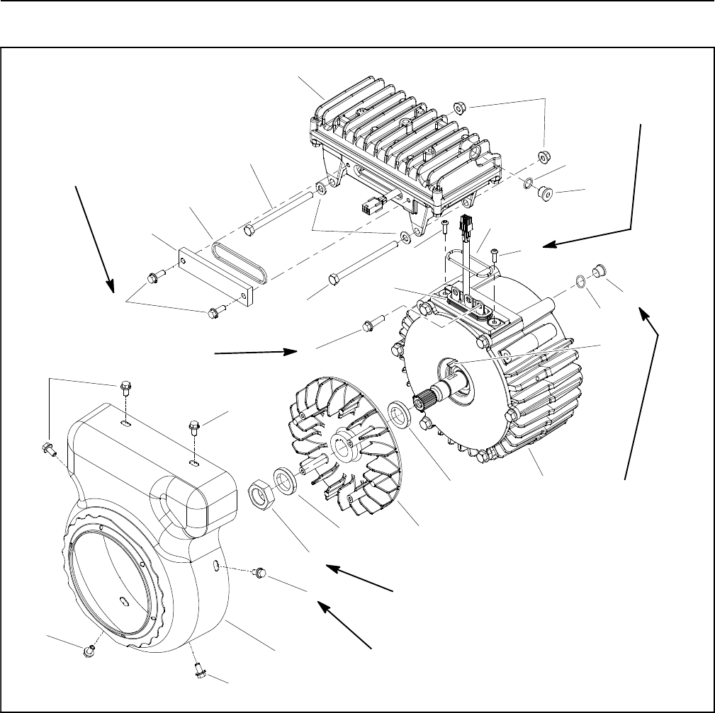
Reelmaster 5010- HPage 5 - 96Electrical System
Motor/Generator Assembly Service
1. Controller assembly
2. Motor/generator assembly
3. Motor/generator cover
4. Flange head screw (3 used)
5. Washer head screw (6 used)
6. Washer head screw (2 used)
7. Access cover
8. Cover gasket
9. Flat washer (2 used)
10. Flange nut (2 used)
11. Cap screw (2 used)
12. Plug (2 used)
13. O- ring
14. Button head screw (2 used)
15. O- ring
16. Woodruff key
17. Motor/generator fan
18. Spacer (2 used)
19. Nut
20. Isolator
Figure 99
70 to 80 in- lb
(8.0 to 9.0 N- m)
75 in- lb
(8.5 N- m)
70 to 80 in- lb
(8.0 to 9.0 N- m)
20 to 26 ft- lb
(28 to 35 N- m)
35 to 45 in- lb
(4.0 to 5.0 N- m)
8
11
13
1
7
12
14
15
16
17
18
4
19
3
5
611
5
9
10
14
18
5
2
5
5
12
13
20
95 to 105 ft- lb
(129 to 142 N- m)
IMPORTANT: When working on the motor/genera-
tor, use a clean work space with a non- metal sur-
face. The motor/generator rotor includes very
powerful magnets that can cause the rotor to move
unexpectedly if working on a metal surface. Also,
any metallic debris that gets attracted to the rotor
can damage the motor/generator after assembly.
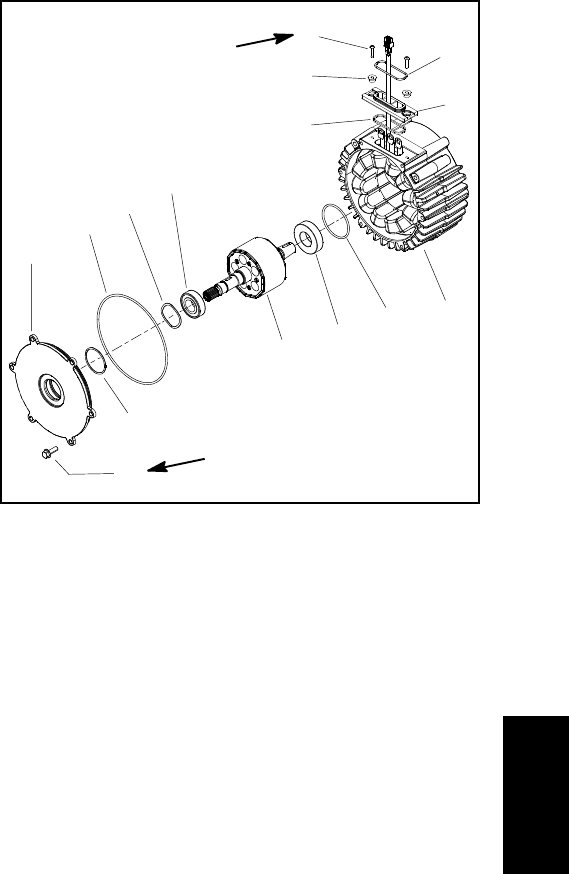
Reelmaster 5010- H Page 5 - 97 Electrical System
Disassembly (Fig. 99)
1. Remove motor/generator cover (item 3) from motor/
generator assembly.
2. Remove access cover (item 7) and cover gasket
from controller. Discard cover gasket.
3. Carefully remove motor/generator and controller
harness connectors from controller opening. Note posi-
tion of connectors and wire harnesses for assembly pur-
poses. Unplug connectors.
4. Remove three (3) flange head screws (item 4) that
secure motor/generator stator conductors to controller
connectors.
5. Remove cap screws (item 11), flat washers (item 9)
and flange nuts (item 10) that secure controller to motor/
generator assembly. Lift controller from motor/genera-
tor. Remove and discard O- ring (item 15).
NOTE: If controller (item 1) damage exists, controller
replacement is necessary. Internal controller compo-
nents are not available separately.
6. Remove nut (item 19) that secures fan to motor/gen-
erator shaft.
7. Remove motor/generator fan and two (2) spacers
from motor/generator shaft. Locate and retrieve
woodruff key.
8. Remove internal motor/generator assembly compo-
nents (Fig. 100):
A. Remove six (6) flange head screws that secure
cover to housing. Leave cover on rotor shaft.
IMPORTANT: The rotor magnets are very power-
ful and can cause the rotor to shift position very
rapidly during removal. Use generator rotor tool
set (see Special Tools in this chapter) to remove
rotor. Be cautious during rotor removal to pre-
vent component damage or personal injury.
B. Use generator rotor tool set (see Special Tools in
this chapter) to carefully remove rotor assembly in-
cluding cover from housing. Follow removal proce-
dure listed in Special Tool section.
C. Remove cover from rotor assembly. Remove O-
rings and wave washer from cover. Discard O- rings.
D. Remove and discard O- ring from housing groove
in bearing bore.
E. If necessary, remove bearings from rotor. Discard
bearings if removed.
F. If necessary, remove isolator from housing as-
sembly.
1. Housing/stator assembly
2. O- ring
3. Bearing
4. Rotor assembly
5. Bearing
6. Wave washer
7. O- ring
8. O- ring
9. Cover
10. Flange screw (6 used)
11. Screw (2 used)
12. O- ring
13. Spacer (2 used)
14. Isolator
15. Gasket
Figure 100
170 to 190 in- lb
(19.3 to 21.4 N- m)
2
3
6
8
9
10
1
5
7
4
11 12
13
14
15
35 to 45 in- lb
(4.0 to 5.0 N- m)
9. Inspect rotor assembly for wear or damage. Also, in-
spect motor/generator housing/stator assembly for evi-
dence of damage.
NOTE: If motor/generator housing/stator damage ex-
ists, motor/generator assembly replacement is neces-
sary. The motor/generator housing and stator are not
available separately.
Assembly (Fig. 99)
1. Make sure that all motor/generator components are
cleaned before assembly.
2. Install internal motor/generator assembly compo-
nents (Fig. 100):
A. If bearings were removed from rotor assembly,
install new bearings onto rotor shaft. Make sure that
new bearings are fully pressed onto rotor shaft.
B. If isolator was removed, lubricate new gasket
with dielectric lubricant (see Special Tools in this
chapter) and install to isolator. Fit isolator to housing
assembly making sure that stator conductors and
stator harness are correctly positioned in isolator.
Secure isolator with spacers and screws. Torque
screws from 35 to 45 in- lb (4.0 to 5.0 N- m).
Electrical
System
Reelmaster 5010- HPage 5 - 98Electrical System
C. Lubricate new O- ring (item 2) with dielectric lubri-
cant (see Special Tools in this chapter) and install
into groove in housing bearing bore.
IMPORTANT: The rotor magnets are very power-
ful and can cause the rotor to shift position very
rapidly during installation. Use generator rotor
tool set (see Special Tools in this chapter) to in-
stall rotor. Be cautious during rotor installation
to prevent component damage or personal inju-
ry.
D. Use generator rotor tool set (see Special Tools in
this chapter) to carefully install rotor assembly into
housing. Make sure that rotor bearing is fully seated
in housing.
E. Lubricate new O- rings (items 7 and 8) with di-
electric lubricant (see Special Tools in this chapter)
and install O- rings into grooves in cover. Place wave
washer in cover bearing bore.
F. Install cover to housing and secure with six (6)
flange head screws. Torque screws from 170 to 190
in- lb (19.3 to 21.4 N- m).
G. Make sure that rotor rotates before continuing
with motor/generator assembly.
3. Install motor/generator fan:
A. Position woodruff key (item 16) into slot on rotor
shaft.
B. Slide spacer, motor/generator fan and then sec-
ond spacer onto motor/generator shaft.
C. Secure fan to motor/generator shaft with nut
(item 19). Torque nut from 95 to 105 ft- lb (129 to
142 N- m).
4. Lubricate new O- ring with dielectric lubricant (see
Special Tools in this chapter) and install into groove on
isolator.
5. Install controller onto motor/generator:
A. Lower controller onto motor/generator and route
both controller and motor/generator harness con-
nectors out opening in controller.
IMPORTANT: When securing stator conductors
to controller connectors, make sure that flange
head screws do not pinch electrical harnesses.
B. Loosely install three (3) flange head screws (item
4) that secure motor/generator stator conductors to
controller connectors. Make sure that controller and
motor/generator harnesses are positioned away
from the screws.
C. Secure controller with cap screws (item 11), flat
washers (item 9) and flange nuts (item 10).
D. Torque three (3) flange head screws (item 4) to 75
in-lb(8.5 N-m).
E. Pack controller harness connector with dielectric
lubricant (see Special Tools in this chapter). Plug
motor/generator connector into controller connector.
Insert harnesses and connectors to the right side of
the three (3) terminals in the controller.
6. Lubricate new cover gasket (item 8) with dielectric lu-
bricant (see Special Tools in this chapter). Install gasket
into groove in access cover (item 7) and then install cov-
er to controller. Secure cover with two (2) washer head
screws. Torque screws from 70 to 80 in- lb (8.0 to 9.0
N-m).
7. Install motor/generator cover (item 3) to motor/gen-
erator assembly and secure with washer head screws.
Torque screws from 70 to 80 in- lb (8.0 to 9.0 N- m).

Reelmaster 5010- H Page 6 - 1 Chassis
Chapter 6
Chassis
Table of Contents
SPECIFICATIONS 2............................
GENERAL INFORMATION 2.....................
Traction Unit Operator’s Manual 2..............
48 VDC Battery Disconnect 2..................
SPECIAL TOOLS 3.............................
SERVICE AND REPAIRS 4......................
Wheels 4....................................
Steering Column 6............................
Brake Service 8..............................
Rear Wheel Bearings (2 Wheel Drive) 12........
Rear Axle 14.................................
Rear Axle Service 16..........................
Control Arm 18...............................
Operator Seat 20.............................
Mechanical Seat Suspension 22................
FrontLiftArms 24.............................
Rear Lift Arms 26.............................
Hood 30.....................................
Chassis
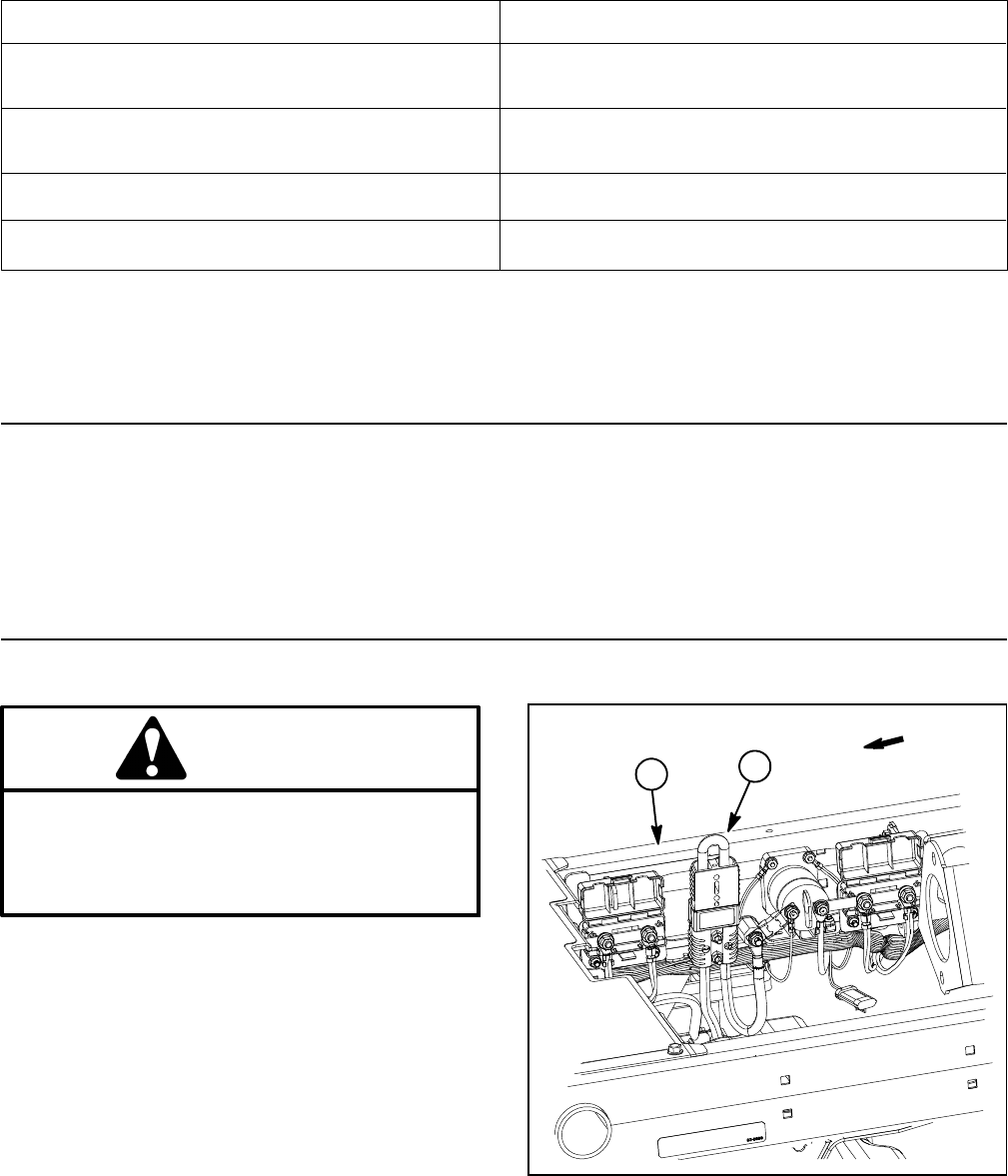
Reelmaster 5010- HPage 6 - 2Chassis
Specifications
Item Description
Front Tire Pressure 12 to 15 PSI (83 to 103 kPa)
(26.5 x 14.0 - 12, 4 ply, tubeless)
Rear Tire Pressure 12 to 15 PSI (83 to 103 kPa)
(20 x 12.0 - 10, 4 ply, tubeless)
Wheel Lug Nut Torque 70 to 90 ft- lb (95 to 122 N- m)
Wheel Motor/Wheel Hub Lock Nut Torque 315 to 385 ft- lb (428 to 522 N- m)
General Information
Traction Unit Operator’s Manual
The Traction Unit Operator’s Manual provides informa-
tion regarding the operation, general maintenance and
maintenance intervals for your Reelmaster machine.
Refer to that publication for additional information when
servicing the machine.
48 VDC Battery Disconnect
CAUTION
Before installing, removing or servicing compo-
nents in the 48 VDC system (e.g. cutting unit mo-
tors, motor/generator), separate the 48 VDC bat-
tery disconnect. This will prevent unexpected
operation of 48 VDC system components.
The 48 VDC battery disconnect is attached to the right
frame rail under the operator seat (Fig. 1). Unplug the
disconnect to make sure that 48 VDC components do
not operate unexpectedly. Apply dielectric grease to the
contact surfaces of the battery disconnect and plug the
battery disconnect back in after service to the 48 VDC
system is completed.
1. RH frame rail 2. 48V battery disconnect
Figure 1
2
1
FRONT
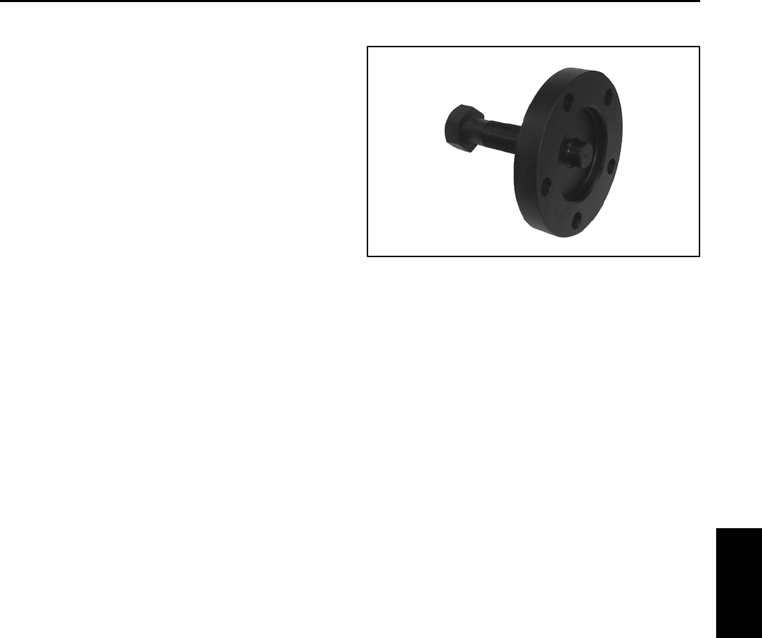
Reelmaster 5010- H Page 6 - 3 Chassis
Special Tools
Order Toro special tools from your Toro Distributor.
Wheel Hub Puller
The wheel hub puller allows safe removal of the front
wheel hub from the wheel motor shaft. If machine is
equipped with optional CrossTraxTM Kit, this wheel hub
puller is needed for removing rear wheel hub from the
rear wheel motor.
Toro Part Number: TOR6004
Figure 2
Chassis
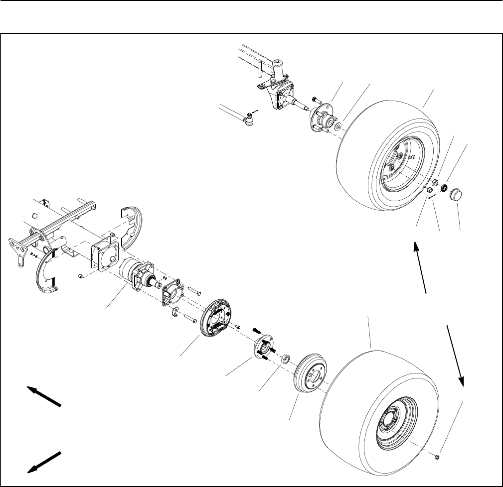
Reelmaster 5010- HPage 6 - 4Chassis
Service and Repairs
Wheels
1. Front wheel motor
2. Brake assembly
3. Front wheel hub
4. Lock nut
5. Brake drum
6. Front wheel
7. Lug nut (5 used per wheel)
8. Rear wheel hub
9. Spindle washer
10. Rear wheel
11. Jam nut
12. Retainer
13. Cotter pin
14. Dust cap
Figure 3
FRONT
RIGHT
70 to 90 ft- lb
(95 to 122 N- m)
2
3
1
4
5
6
7
8910
11
12
13 14
7
2 WHEEL DRIVE AXLES SHOWN
Reelmaster 5010- H Page 6 - 5 Chassis
Removal (Fig. 3)
1. Park machine on a level surface, lower cutting units,
stop engine, engage parking brake and remove key
from the ignition switch.
2. Chock wheels to prevent machine from shifting.
3. Loosen, but do not remove, wheel lug nuts.
When changing tires, attachments or perform-
ing other service, use correct hoists, jacks and
jack stands. Make sure machine is parked on a
solid, level surface such as a concrete floor.
Prior to raising machine, remove any attach-
ments that may interfere with the safe and prop-
er raising of the machine. Always chock or
block wheels. Use jack stands or other ap-
propriate load holding devices to support the
raised machine. If the machine is not properly
supported, the machine may move or fall, which
may result in personal injury.
CAUTION
4. Using a jack, raise machine so wheel is off ground
(see Jacking Instructions in Chapter 1 - Safety). Sup-
port machine with jack stands.
5. Remove wheel lug nuts and then remove wheel from
machine.
Installation (Fig. 3)
1. Install wheel and secure with five (5) wheel lug nuts.
2. Lower machine to ground.
WARNING
Failure to maintain proper wheel lug nut torque
could result in failure or loss of wheel and may
result in personal injury.
3. Torque wheel lug nuts evenly in a crossing pattern
from 70 to 90 ft- lb (95 to 122 N- m).
Chassis
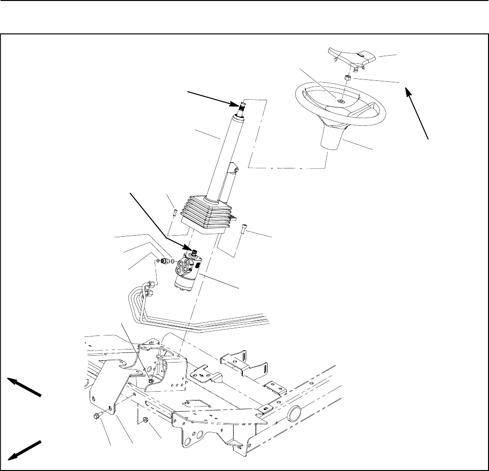
Reelmaster 5010- HPage 6 - 6Chassis
Steering Column
1. Steering column
2. Steering wheel
3. Steering wheel cover
4. Lock nut
5. Flat washer
6. Socket head screw (4 used)
7. Steering control valve
8. Column brace
9. Flange nut (6 used)
10. Flange head screw (2 used)
11. Socket head screw (4 used)
12. O- ring
13. Hydraulic fitting (4 used)
14. O- ring
Figure 4
FRONT
RIGHT
1
13
14
10
11
5
9
2
3
12
9
7
4
6
8
20 to 26 ft- lb
(28 to 35 N- m)
Antiseize
Lubricant
Antiseize
Lubricant
Removal (Fig. 4)
1. Park the machine on a level surface, engage the
parking brake, lower the cutting units and stop the en-
gine. Remove the key from the ignition switch.
2. Remove cover from steering wheel by carefully pry-
ing up on one of the cover spokes.
3. Remove lock nut and flat washer that secure steer-
ing wheel to steering column.
4. Use a suitable puller to remove steering wheel from
steering column.
5. Remove platform shroud from machine to allow ac-
cess to steering column fasteners (Fig. 5).
A. Remove cover plate from platform.
B. Remove fasteners that secure platform shroud to
machine and remove platform shroud
C. Retrieve two (2) rubber bushings and spacers.
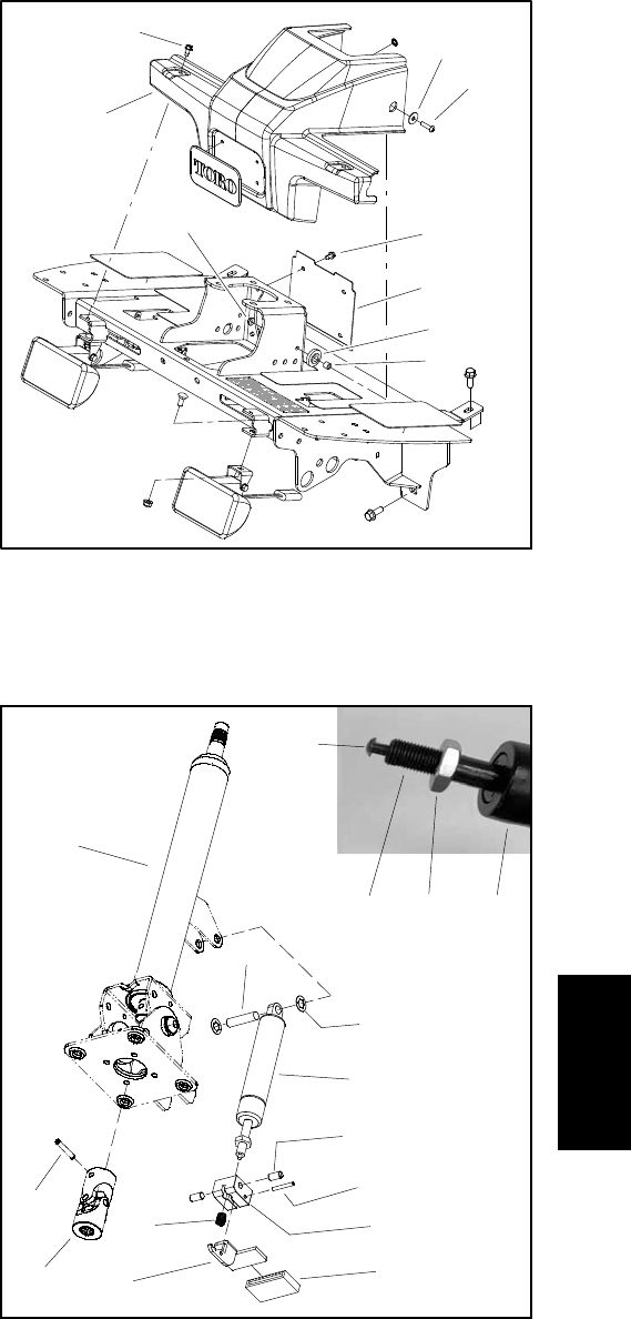
Reelmaster 5010- H Page 6 - 7 Chassis
6. Slide rubber bellows up steering column to allow ac-
cess to fasteners that secure steering column to ma-
chine.
7. Support steering control valve to prevent it from shift-
ing during steering column removal.
8. Loosen and remove four (4) socket head screws
(item 6) that secure steering control valve to steering
column.
9. Loosen and remove four (4) socket head screws
(item 11) and flange nuts (item 9) that secure steering
column to machine.
10.Slide steering column assembly from steering con-
trol valve and machine.
11.Disassemble steering column assembly as needed
using Figure 6 as a guide.
Installation (Fig. 4)
1. Assemble steering column using Figure 6 as a guide.
Afterassembly,makesurethatreleasepinonendofcyl-
inder shaft is positioned against the pedal. Jam nut on
cylinder shaft can be used to adjust location of release
pin.
2. Apply antiseize lubricant to input shaft of steering
control valve.
3. Slide steering column onto steering control valve.
Secure steering column in place with four (4) socket
head screws (item 11) and flange nuts (item 9).
4. Secure steering control valve to steering column with
four (4) socket head screws (item 6).
5. Slide rubber bellows to bottom of steering column.
6. Place rubber bushings and spacers into holes of
platform shroud (Fig. 5). Position platform shroud in
place and secure with removed fasteners.
7. Thoroughly clean tapered surfaces of steering wheel
and steering column.
8. Apply antiseize lubricant to splines of steering col-
umn taking care to keep antiseize lubricant from column
taper. Slide steering wheel onto steering column.
9. Secure steering wheel to steering column with flat
washer and lock nut. Torque hex nut from 20 to 26 ft- lb
(28to35N-m).
10.Install steering wheel cover to steering wheel.
1. Washer (2 used)
2. Screw (2 used)
3. Screw (6 used)
4. Platform shroud
5. Lock nut (2 used)
6. Cover plate
7. Bushing (2 used)
8. Spacer (2 used)
Figure 5
3
4
1
2
53
6
7
8
Figure 6
1. Steering column
2. Pin
3. Universal joint
4. Pin
5. Lock washer (2 used)
6. Cylinder
7. Bolt (2 used)
8. Pin
9. Pedal block
10. Pedal cover
11. Pedal
12. Spring
13. Release pin
14. Cylinder shaft
15. Jam nut
2
3
4
5
6
1
7
8
9
10
12
11
6
13
14 15
Chassis
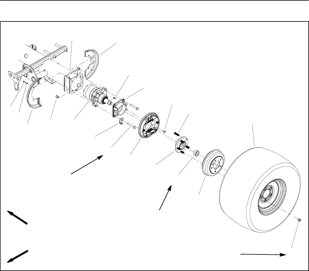
Reelmaster 5010- HPage 6 - 8Chassis
Brake Service
1. Wheel motor (LH shown)
2. Lug nut (5 used per wheel)
3. Wheel hub
4. Wheel stud (5 used per wheel)
5. Wheel assembly
6. Brake drum
7. Front wheel shield (2 used)
8. Cap screw (2 used per shield)
9. Flat washer (2 used per shield)
10. Lock nut (2 used per shield)
11. Rear wheel shield (LH shown)
12. Lock nut
13. Square key
14. Brake assembly (LH shown)
15. Cap screw (4 used per brake assy)
16. Cap screw (4 used per motor)
17. Spring clip (LH shown)
18. Lock nut (4 used per motor)
19. Brake adapter
Figure 7
(428 to 522 N- m)
315 to 385 ft- lb
FRONT
RIGHT
70 to 90 ft- lb
(95 to 122 N- m) 2
3
1
4
5
6
8
9
10 11
13
7
12
14
15
16
17
18
19
80 to 100 ft- lb
(109 to 135 N- m)
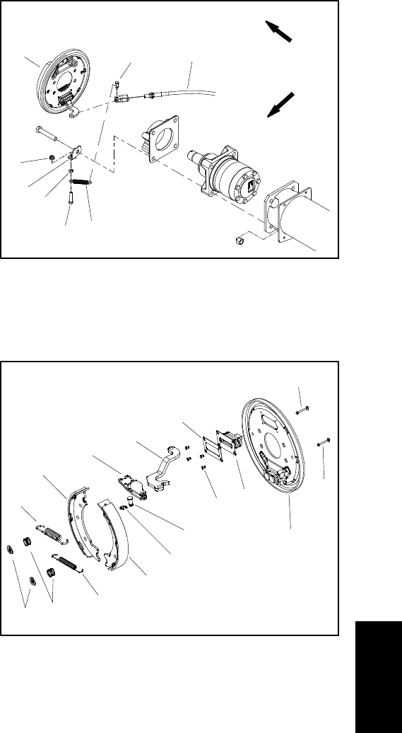
Reelmaster 5010- H Page 6 - 9 Chassis
Removal (Fig. 7)
1. Park the machine on a level surface, lower the cut-
ting units and stop the engine. Remove the key from the
ignition switch.
2. Chock wheels to prevent machine from shifting.
3. Loosen, but do not remove, lock nut (item 12) from
wheel motor shaft.
4. Remove front wheel assembly (see Wheels in this
section). Make sure to support raised machine with ap-
propriate jack stands.
5. Make sure parking brake is disengaged.
NOTE: Clevis pin that secures brake cable to brake ac-
tuator lever is secured with extension spring (shown in
Fig. 8).
6. Remove extension spring from clevis pin that se-
cures brake cable to brake actuator lever (Fig. 8). Re-
move clevis pin and position brake cable away from
brake actuator lever.
7. Remove brake drum.
IMPORTANT: DO NOT hit wheel hub, puller or wheel
motor with a hammer during wheel hub removal or
installation. Hammering may cause damage to the
wheel motor.
8. Make sure that lock nut on wheel motor shaft is
loose. Use hub puller (see Special Tools in this chapter)
to loosen wheel hub from wheel motor shaft.
9. Remove lock nut and wheel hub from wheel motor
shaft. Locate and retrieve square key.
NOTE: If desired, the complete brake assembly can be
removed from the machine for disassembly (see step
12).
10.Remove upper and lower shoe springs from brake
shoes.
11.Remove shoe hold down cups and hold down
springs. Remove brake shoes and hold down pins from
backing plate.
12.If necessary, remove brake backing plate from ma-
chine by loosening and removing four (4) cap screws
that secure backing plate to brake adapter.
Installation (Fig. 7)
1. Remove rust and debris from all brake parts with a
wire brush prior to installation. Clean all parts. Inspect
brake shoe contact surfaces of the brake drum for ex-
cessive wear. Replace any worn or damaged brake
parts.
1. Brake assembly
2. Clevis pin
3. Spring clip
4. Flange nut
5. Jam nut
6. Cap screw
7. Extension spring
8. Brake cable
Figure 8
FRONT
RIGHT
2
3
6
8
1
5
7
4
RH BRAKE ASSEMBLY SHOWN
1. Backing plate
2. Rivet (4 used)
3. Clevis pin
4. Retaining ring
5. Brake shoe
6. Lower shoe spring
7. Hold down spring
8. Hold down cup
9. Upper shoe spring
10. Brake actuator
11. Actuator lever
12. Back- up plate
13. Boot
14. Hold down pin
Figure 9
10
2
31
4
5
6
8
9
7
5
11
12
13
14
14
RH BRAKE ASSEMBLY SHOWN
2. If backing plate was removed from machine, secure
backing plate to brake adapter with four (4) cap screws.
3. Lightly lubricate brake shoe pivot points with general
purpose grease.
4. Position one brake shoe to the backing plate. Install
brake hold down pin and secure with hold down spring
and cup. Repeat for second brake shoe.
5. Install upper and lower shoe springs to brake shoes.
Make sure that brake shoes are properly positioned to
pivot and actuator points.
Chassis

Reelmaster 5010- HPage 6 - 10Chassis
IMPORTANT: Before wheel hub is installed, thor-
oughly clean tapers of wheel hub and wheel motor
shaft. Make sure that tapers are free of grease, oil
and dirt. DO NOT use antiseize lubricant when
installing wheel hub.
6. Mount square key in the wheel motor shaft, then
install the wheel hub onto the wheel motor shaft.
7. Secure wheel hub onto the wheel motor shaft with
lock nut (item 12).
8. Install brake drum.
9. Position brake cable end to brake actuator lever (Fig.
8). Secure brake cable clevis to brake actuator lever with
clevis pin and extension spring.
10.Install front wheel assembly (see Wheels in this sec-
tion).
11. Check and adjust brakes.
12.Lower machine to ground.
13.Torque wheel lug nuts evenly in a crossing pattern
from 70 to 90 ft- lb (95 to 122 N- m). Torque lock nut
(item 12) that secures wheel hub from 315 to 385 ft- lb
(428 to 522 N- m).
CAUTION
After servicing the brakes, always check the
brakes in a wide open, level area that is free of
other persons and obstructions.

Reelmaster 5010- H Page 6 - 11 Chassis
This page is intentionally blank.
Chassis
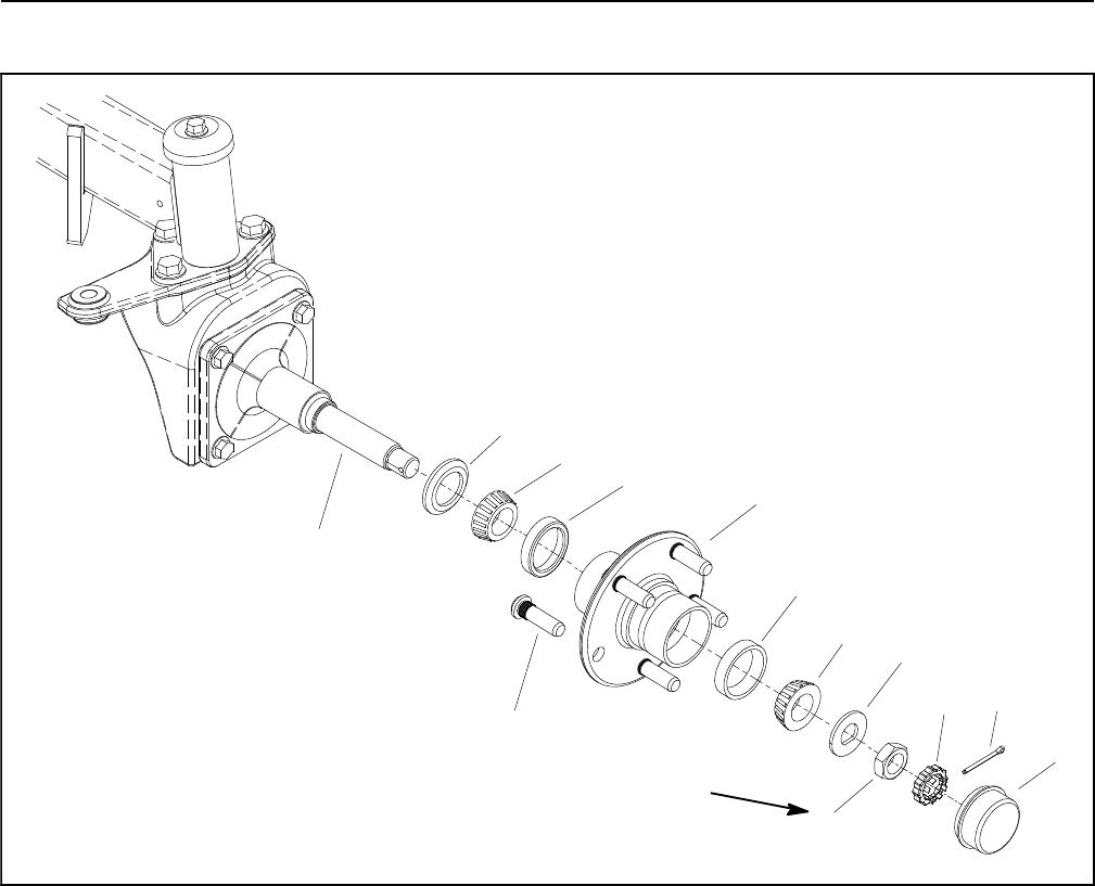
Reelmaster 5010- HPage 6 - 12Chassis
Rear Wheel Bearings (2 Wheel Drive)
1. Dust cap
2. Cotter pin
3. Retainer
4. Jam nut
5. Spindle washer
6. Bearing cone
7. Bearing cup
8. Wheel hub
9. Seal
10. Spindle
11. Wheel stud (5 used)
Figure 10
1
32
8
4
5
7
6
6
10
9
7
11
See text for
tightening
procedure

Reelmaster 5010- H Page 6 - 13 Chassis
Disassembly (Fig. 10)
1. Chock front wheels to prevent machine from shifting.
2. Remove rear wheel (see Wheels in this section).
Make sure to support machine with jack stands.
3. Remove the dust cap from the wheel hub.
4. Remove the cotter pin, retainer, jam nut and spindle
washer. Slide the wheel hub from the spindle shaft.
5. Pull the seal out of the wheel hub. Discard seal.
6. Remove the bearing cones from both sides of the
wheel hub. Clean the bearings in solvent. Make sure the
bearings are in good operating condition. Clean the in-
side of the wheel hub. Check the bearing cups for wear,
pitting or other damage. Replace worn or damaged
parts.
Assembly (Fig. 10)
1. If bearing cups were removed from the wheel hub,
press new cups into the hub until they seat against the
shoulder of the hub.
IMPORTANT: The lip of the seal must be toward the
bearing. The seal should be pressed in so it is flush
with the end of the wheel hub.
2. Pack both bearings with grease. Install one bearing
into the bearing cup on inboard side of the wheel hub.
Lubricate the inside of a new seal and press it into the
wheel hub with the seal lip toward the bearing.
3. Fill wheel hub cavity between bearings approximate-
ly 50% full of grease. Position remaining bearing into the
outer bearing cup.
4. Slide the wheel hub assembly onto the spindle shaft
and secure it in place with the spindle washer and jam
nut. DO NOT fully tighten the nut or install the cotter pin.
5. While rotating the wheel hub by hand, torque the jam
nutfrom75to100in-lb(8.5to11.3N-m)tosetthebear-
ings. Then, loosen the nut until the hub has endplay.
6. While rotating the wheel hub by hand, torque the jam
nut from 15 to 20 in-lb (1.7 to 2.3 N- m). After tightening,
make sure that the wheel hub does not have any free
play.
7. Install retainer with slot aligned to cotter pin hole in
spindle. Install cotter pin.
8. Fill dust cap approximately 50% full of grease. Install
dust cap.
9. Install rear wheel (see Wheels in this section).
10.Lower machine to ground.
11. Torque lug nuts evenly in a crossing pattern from 70
to 90 ft- lb (95 to 122 N- m).
Chassis
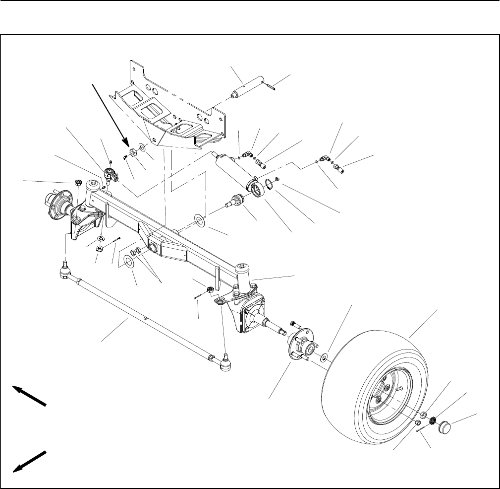
Reelmaster 5010- HPage 6 - 14Chassis
Rear Axle
1. Lug nut (5 used per wheel)
2. Rear axle assembly
3. Dust cap
4. Hydraulic fitting
5. Tie rod
6. Axle pivot pin
7. Thrust washer
8. Roll pin
9. Thrust washer
10. Jam nut
11. Grease fitting
12. Tab washer
13. Wheel hub assembly
14. Grease fitting
15. O- ring
16. Jam nut
17. Nut retainer
18. Hydraulic hose
19. O- ring
20. Cotter pin
21. Steering cylinder
22. Ball joint
23. Ball joint
24. Retaining ring
25. Jam nut
26. Wheel assembly
27. Grease fitting
28. Slotted hex nut
29. Slotted hex nut
30. Washer
31. Hydraulic hose
Figure 11
FRONT
RIGHT
9
10
11
22 4
29
15
3
20
30
20
7
27 19
13
2
12
8
6
23
21
24
18
7
14
16
17
120
26
5
25
27
28
415
19
90 to 120 ft- lb
(123 to 162 N- m)
28
31

Reelmaster 5010- H Page 6 - 15 Chassis
Removal (Fig. 11)
1. Park machine on a level surface, lower cutting units,
stop engine, engage parking brake and remove key
from the ignition switch.
2. Chock front wheels to prevent machine from shifting.
3. Thoroughly clean hydraulic hose ends and fittings on
steering cylinder to prevent hydraulic system contami-
nation.
NOTE: To ease assembly, label hydraulic hoses to
show their correct position on the steering cylinder.
4. Disconnect the hydraulic hoses from the steering
cylinder. Put caps or plugs on all fittings and hoses to
prevent contamination.
5. Remove the jam nut (item 10) and thrust washer
(item 9) that secure the axle pivot pin (item 6) to the
frame.
6. Jack up the machine (just ahead of the rear wheels)
until clearance exists to allow rear axle removal. Sup-
port the machine with jack stands or appropriate load
holding device to prevent it from falling.
7. Support rear axle to prevent it from falling.
8. Pull the axle pivot pin from frame and rear axle. This
will release the rear axle and thrust washers (item 7)
from the frame. Carefully pull the entire axle and wheel
assembly out from under the machine.
Installation (Fig. 11)
1. Thoroughly clean the rear axle pivot pin. Inspect the
pin for wear or damage and replace if necessary.
2. Position the rear axle assembly to the frame. Install
thrust washer (item 7) between each side of axle and
frame. Raise axle assembly to frame and slide pivot pin
through frame, thrust washers and axle. Make sure that
roll pin on pivot pin is positioned in frame reliefs.
3. Install thrust washer (item 9) and jam nut (item 10)
onto pivot pin. Torque jam nut (item 10) from 90 to 120
ft- lb (123 to 162 N- m). Make sure that axle can still piv-
ot freely after jam nut is tightened.
4. Lower the machine to the ground.
5. Correctly install the hydraulic hoses to the steering
cylinder.
6. Check oil level in hydraulic reservoir.
7. Lubricate the rear axle pivot bushings through the
grease fitting on the axle pivot pin.
8. Operate machine and check steering cylinder hy-
draulic connections for leaks.
Chassis
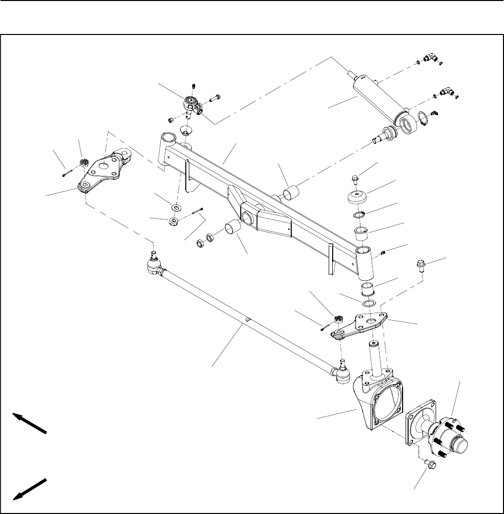
Reelmaster 5010- HPage 6 - 16Chassis
Rear Axle Service
1. Rear axle
2. Housing (2 used)
3. RH drag link
4. Tie rod assembly
5. Pivot bushing (2 used)
6. Grease fitting (2 used)
7. Flange bushing (4 used)
8. Flange head screw (7 used per side)
9. LH drag link
10. Hub and spindle assembly (2 used)
11. Retaining ring
12. Spindle cap
13. Flange head screw
14. Thrust washer
15. Cotter pin
16. Slotted hex nut
17. Steering cylinder
18. Ball joint
19. Washer
20. Slotted hex nut
21. Cotter pin
Figure 12
FRONT
RIGHT
2
311
13
1
12
15
16
4
6
8
9
10
5
7
14
5
7
8
16
15
17
18
19
20
21

Reelmaster 5010- H Page 6 - 17 Chassis
Axle Pivot Bushings (Fig. 12)
Therearaxlemustbeheldinplacesnuglybytheaxle
pivot pin. Excessive movement of the axle, which is
characterized by erratic steering, might indicate worn
axle pivot bushings (item 5). To correct the problem, re-
place the bushings.
1. Remove rear axle from machine (see Rear Axle in
this section).
2. Use a bushing removal tool to extract both axle pivot
bushings from the rear axle pivot tube. Take care to not
damage bore of pivot tube during bushing removal.
Clean the inside of the tube to remove all dirt and foreign
material.
3. Apply grease to the inside and outside of the new
bushings. Use an arbor press to install the bushings into
the front and back of the rear axle pivot tube. Bushings
must be flush with the axle tube after installation.
4. Install rear axle to machine (see Rear Axle in this
section).
Rear Axle Housing Bushings (Fig. 12)
The rear axle housing shafts (item 2) must fit snugly in
the rear axle. Excessive movement of the housing shaft
in the axle might indicate that the flange bushings (item
7) are worn and must be replaced.
1. Remove rear axle from machine (see Rear Axle in
this section).
2. Remove cotter pin and slotted hex nut that secure
the tie rod end to the drag link. Separate the tie rod end
from the drag link.
3. If right side housing is being removed from axle, re-
move cotter pin, washer and slotted hex nut that secure
steering cylinder ball joint (item 18) to RH drag link. Sep-
arate steering cylinder from drag link.
4. Remove the flange head screw (item 12), spindle
cap (item 13) and retaining ring (item 11) that secure the
housing shaft into the rear axle tube. Slide the housing
and wheel assembly out of the axle tube to expose the
flange bushings. Locate and retrieve thrust washer
(item 14) from housing shaft.
5. Use a bushing removal tool to extract both flange
bushings (item 7) from the axle tube. Take care to not
damage the bore of the axle tube. Clean the inside of the
axle tube to remove all dirt or foreign material.
6. Apply grease to the inside and outside of the new
flange bushings. Use an arbor press to install the bush-
ings into the top and bottom of the axle tube. Press bush-
ings into tube until flange shoulder bottoms on tube.
7. Thoroughly clean the housing shaft. Inspect the
shaft for wear and replace if worn or damaged.
8. Install thrust washer (item 14) onto the housing shaft
and slide the shaft up through the rear axle tube. Hold
the housing shaft and wheel assembly in place and
install the retaining ring (item 11) onto the housing shaft.
Make sure that retaining ring is fully seated into housing
shaft groove after installation.
9. Install the spindle cap (item 13) and flange head
screw (item 12).
10.Connect the tie rod end to the drag link with slotted
hex nut and cotter pin.
11. If separated, secure steering cylinder ball joint to RH
drag link with slotted hex nut, washer and cotter pin.
12.Install rear axle to machine (see Rear Axle in this
section).
13.Lubricate the steering spindles through the grease
fittings on the rear axle.
14.Check rear wheel toe- in (see Traction Unit Opera-
tor’s Manual).
15.After all adjustments have been made, make sure
that no contact is made between any machine compon-
ents as the wheels are moved from lock to lock. Adjust
if necessary.
Chassis
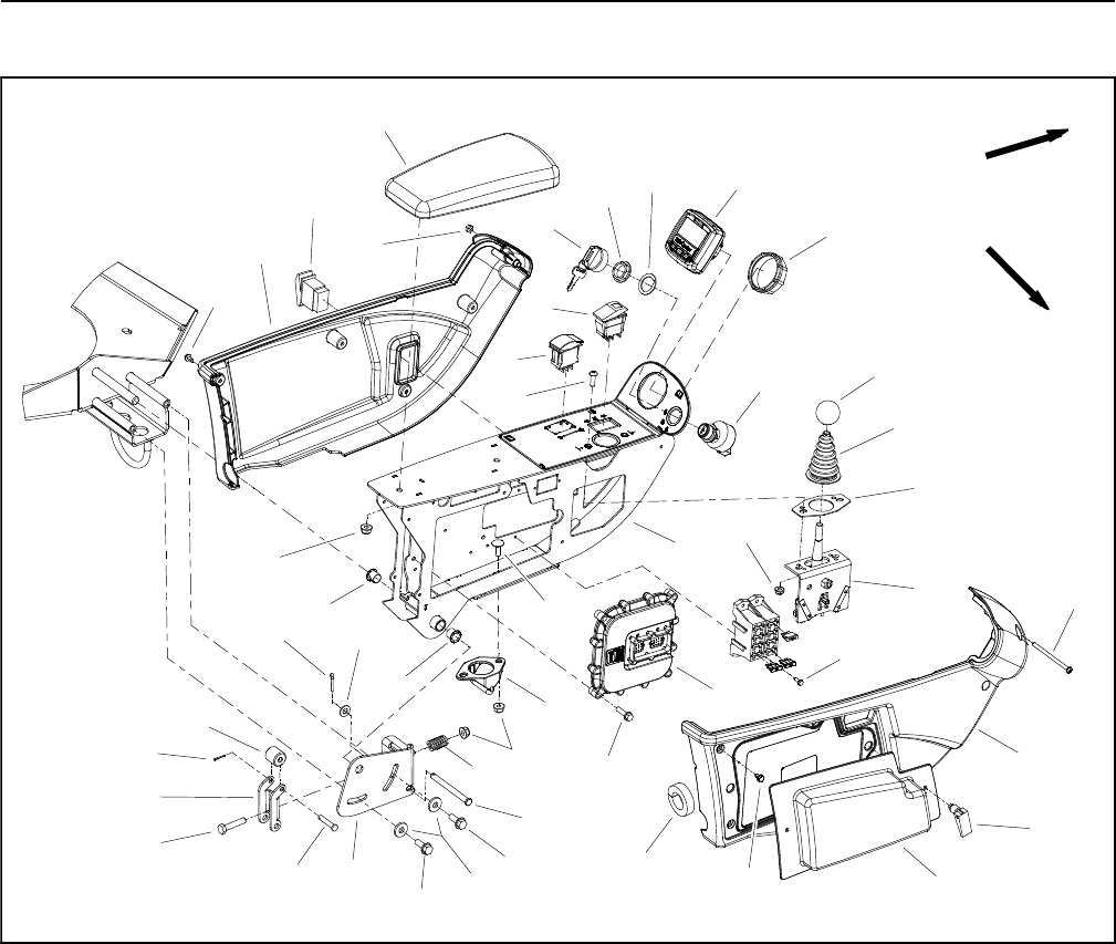
Reelmaster 5010- HPage 6 - 18Chassis
Control Arm
1. Control arm frame
2. InfoCenter display
3. Headlight switch
4. Reel engage/disengage switch
5. Screw (4 used)
6. Carriage screw (2 used)
7. Latch
8. Joystick assembly
9. Flange nut (2 used)
10. Screw (2 used)
11. Swell latch (2 used)
12. Washer head screw (10 used)
13. Bushing (2 used)
14. Flange nut (5 used)
15. RH control arm cover
16. LH control arm cover
17. Knob
18. Boot
19. Boot plate
20. Ignition switch
21. Engine speed switch
22. Cotter pin
23. Lock nut
24. Key set
25. Mounting nut
26. Backup washer
27. Flat washer
28. Screw
29. Access cover
30. Spacer
31. TEC controller
32. Washer head screw (4 used)
33. Arm rest
34. Foam seal
35. Compression spring
36. Clevis pin
37. Screw (2 used)
38. Flat washer (2 used)
39. Retainer bracket
40. Clevis pin
41. Cap screw
42. Latch
43. Cotter pin
44. Nut
Figure 13
FRONT
RIGHT
2
3
6
8
9
10
11
13
1
5
7
12
14
15
16
17
18
19
20
4
21
23
24
25 26
28
29
31
32
33
34
35
36
37
38
39
40
41
42
43
30
27
22
13
14
37
12
44
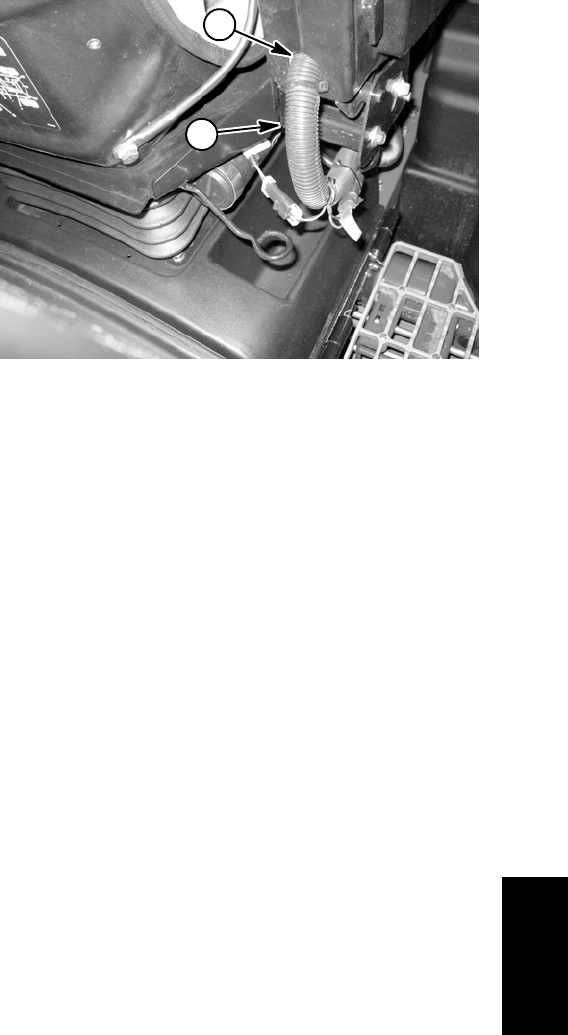
Reelmaster 5010- H Page 6 - 19 Chassis
Disassembly (Fig. 13)
1. Park machine on a level surface, lower cutting units,
stop engine and engage parking brake. Remove key
from ignition switch.
2. Loosen latches and remove access cover from out-
side of control arm.
3. At front of control arm, remove screw (item 28) and
lock nut (item 23) that secure control arm covers to each
other.
4. Remove five (5) washer head screws (item 12) that
secure each cover to control arm.
5. Remove control arm covers from machine. As LH
control arm cover (item 16) is removed from control arm,
unplug wire harness connector from headlight switch.
6. Remove electrical components from control arm as
needed using Figure 13 as a guide.
Assembly (Fig. 13)
1. Install all removed electrical components to control
arm using Figure 13 as a guide.
2. Position covers to control arm. As LH cover (item 16)
is placed, plug wire harness connector to headlight
switch. Also, make sure that wire harness is routed cor-
rectly through cover openings (shown in Fig. 14).
3. Secure each cover to control arm with five (5) washer
head screws (item 12). Install screw (item 28) and lock
nut (item 23) to secure covers at front of control arm.
4. Install access cover to outside of control arm.
1. Wire harness 2. Harness foam seal
Figure 14
1
2
Chassis
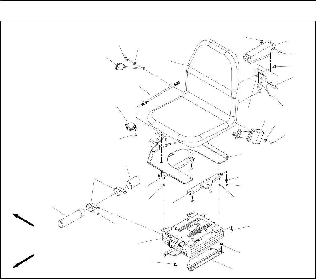
Reelmaster 5010- HPage 6 - 20Chassis
Operator Seat
1. Operator seat
2. Seat base
3. Seat adjuster w/latch
4. Flat washer (4 used)
5. Seat switch harness
6. Seat switch
7. Washer head screw (2 used)
8. Armrest bracket
9. Spacer
10. Armrest
11. Cap screw
12. Flange nut
13. Flat washer (4 used)
14. Flange head screw (3 used)
15. Socket head screw (4 used)
16. Seat adjuster
17. Flat washer
18. Seat bracket (2 used)
19. Cap screw (4 used)
20. Housing cap
21. R- clamp (2 used)
22. Manual housing
23. Seat belt buckle
24. Flange nut (4 used)
25. Seat suspension
26. Flange head screw (4 used)
27. Cap screw (2 used)
28. Lock washer (2 used)
29. Seat belt
Figure 15
15
4
16
1
2
7
6
12 10
11
14
9
17 8
3
5
13
20
24
25
22
23
19
18
24
FRONT
RIGHT
21
26
27
28
29
27 28
13
IMPORTANT: The operator seat, seat base and con-
trol arm assembly are attached to the machine with
the same fasteners. Make sure to support the seat
base and control arm to prevent them from shifting
when removing the seat. Damage to control arm
electrical components and control arm wiring har-
ness can occur if the seat base and control arm are
not properly supported during seat removal.
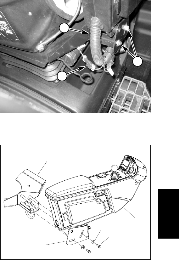
Reelmaster 5010- H Page 6 - 21 Chassis
Removal (Fig. 15)
1. Park machine on a level surface, lower cutting units,
stop engine, engage parking brake and remove key
from the ignition switch.
2. Disconnect negative battery cable from 12 volt bat-
teryatrearofmachine(see12VoltBatteryServiceinthe
Service and Repairs section of Chapter 5 - Electrical
System).
3. Disconnect seat switch electrical connector from
wire harness (Fig. 16).
4. Remove two (2) flange head screws and flat washers
that secure retainer bracket assembly and control arm
assembly to seat base (Fig. 17). Remove retainer brack-
et assembly.
IMPORTANT: Take care to not damage the electrical
wire harness when removing seat and control arm
assembly from machine.
5. Carefully slide control arm assembly from seat base.
Make sure that two (2) bushings remain in pivot of con-
trol arm assembly. Position and support control arm as-
sembly to allow seat removal.
6. Remove four (4) socket head screws (item 15) and
flat washers (item 4) that secure seat and seat base to
seat adjusters. Note location of fasteners for assembly
purposes.
7. Support seat base to keep it positioned on seat ad-
justers.
8. Remove operator seat from seat base and seat ad-
justers. Note location of fasteners for assembly purpos-
es.
Installation (Fig. 15)
1. Position seat and seat base to seat adjusters. Use
forward set of mounting holes in bottom of seat when
aligning seat with seat base and adjusters.
2. Secure seat and seat base to seat adjusters with four
(4) flat washers (item 4) and socket head screws (item
15).
IMPORTANT: Take care to not damage electrical
wire harness when installing control arm assembly
to machine.
3. Make sure that two (2) bushings are positioned in
control arm pivot area. Carefully slide control arm as-
sembly onto seat base post.
4. Position retainer bracket assembly to control arm
and secure with two (2) flange head screws and flat
washers (Fig. 17).
5. Connect seat switch electrical connector to wire har-
ness.
6. Connect negative battery cable to 12 volt battery at
rear of machine (see 12 Volt Battery Service in the Ser-
vice and Repairs section of Chapter 5 - Electrical Sys-
tem).
1. Seat switch lead
2. Wire harness
3. Flange screw
Figure 16
1
2
3
1. Seat base
2. Control arm assembly
3. Flange screw (2 used)
4. Flat washer (2 used)
5. Retainer bracket assy
Figure 17
1
2
3
4
5
Chassis
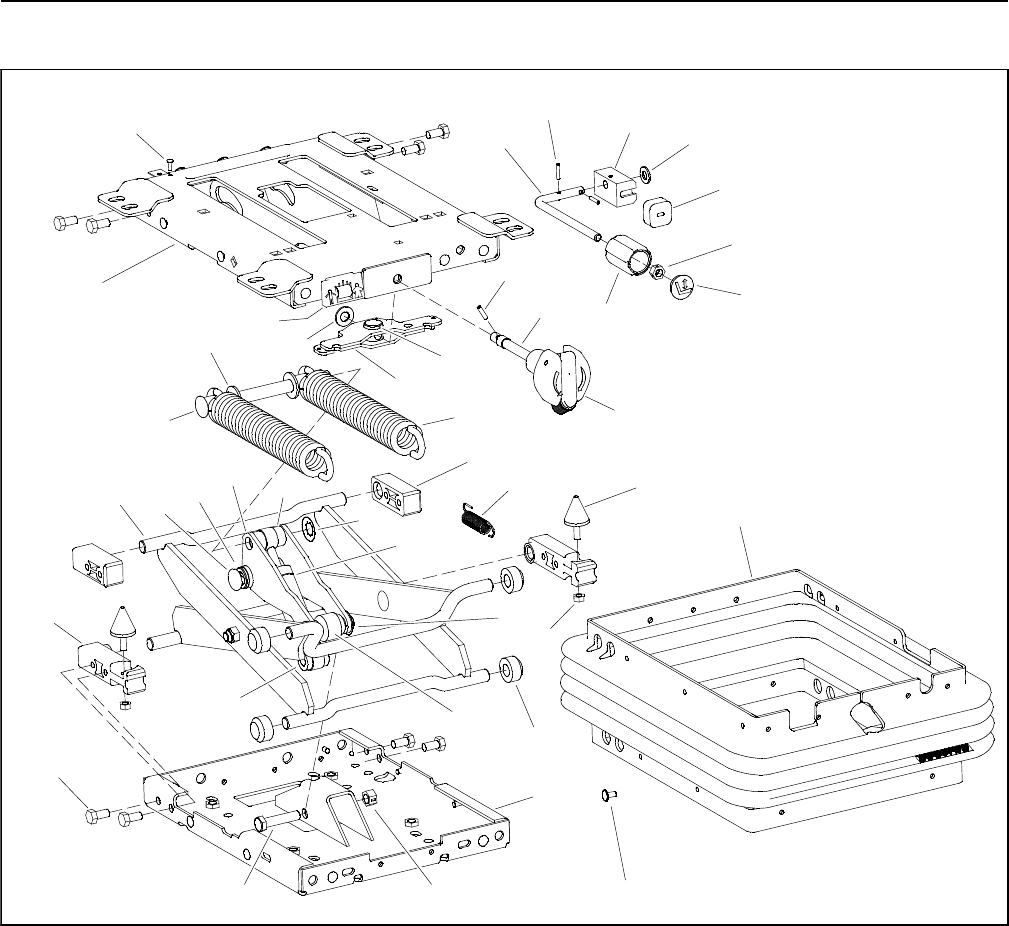
Reelmaster 5010- HPage 6 - 22Chassis
Mechanical Seat Suspension
1. Upper housing
2. Weight adjust knob
3. Lower housing
4. Scissor assembly
5. Lock nut
6. Weight adjuster
7. Drive arm
8. Extension spring (2 used)
9. Roller guide
10. Weight adjust knob
11. Cap
12. Suspension boot
13. Pivot block (2 used)
14. Damper
15. Lower shock bolt
16. Upper shock bushing (2 used)
17. Lower shock bushing (2 used)
18. Stop bumper
19. Height adjust rod
20. Lock nut
21. Stop bumper (2 used)
22. Bearing tube (2 used)
23. Spring shaft
24. Pivot pin
25. Roller pin
26. Spring bushing (2 used)
27. Shaftblock(2used)
28. Weight adjust spacer
29. Weight indicator assembly
30. Weight adjust nut
31. Rivet
32. Roller (4 used)
33. Extension spring
34. Bumper
35. Hex nut (2 used)
36. Retainer (3 used)
37. Flat washer
38. Flat washer
39. Thread forming screw (8 used)
40. Roll pin (2 used)
41. Roll pin
42. Clip (20 used)
Figure 18
5
4
7
6
1
9
11
8
3
2
10
12
13
14
15
16
17
18
19
20
21
24
25
22
23
26
27
28
29
30
31
32
33
34
35
36
37
38
39
40
41
42
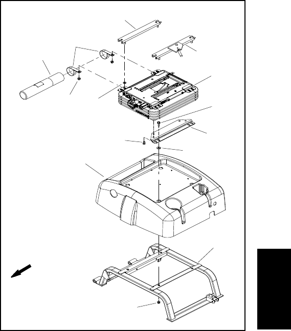
Reelmaster 5010- H Page 6 - 23 Chassis
IMPORTANT: When removing the seat suspension,
make sure to support the control arm to prevent
damage to the control arm electrical components
and control arm wiring harness.
Removal (Figs. 18 and 19)
1. Park machine on a level surface, lower cutting units,
stop engine, engage parking brake and remove key
from the ignition switch.
2. Disconnect negative battery cable from 12 VDC bat-
tery (see 12 Volt Battery Service in the Service and Re-
pairs section of Chapter 5 - Electrical System).
3. Remove seat from machine(seeOperatorSeatin
this section).
IMPORTANT: Take care to not damage the electrical
harness when removing seat suspension from ma-
chine.
4. Tilt and support seat frame to allow access to seat
suspension fasteners.
5. Support seat suspension to prevent it from falling.
Remove four (4) flange head screws (item 8 in Figure
19) and flange nuts (item 5 in Figure 19) that secure seat
suspension with attached seat brackets to seat base.
6. Remove seat suspension assembly from machine.
Locate and retrieve four (4) spacers (item 7 in Figure 19)
from between seat suspension assembly and seat
base.
7. Remove seat suspension components as needed
using Figures 18 and 19 as guides.
Installation (Figs. 18 and 19)
1. Install all removed seat suspension components us-
ingFigures18and19asguides.
A. If seat adjusters (items 12 or 13 in Figure 19) were
removed from seat suspension, install adjuster studs
in rear set of holes in the suspension. Also, make
sure that washer (item 9 in Figure 19) is placed be-
tween seat adjuster and suspension.
IMPORTANT: Take care to not damage the electrical
harness when installing seat suspension to ma-
chine.
2. Position seatbase cover and four (4) spacers (item
7 in Figure 19) to seat base.
3. Position seat suspension with attached seat brack-
ets to seat base. Use rear set of mounting holes in seat
brackets when aligning seat suspension assembly with
seat base. Secure with four (4) flange head screws (item
8 in Figure 19) and flange nuts (item 5 in Figure 19).
4. Install seat to machine (see Operator Seat in this
section). Make sure to connect wire harness electrical
connector to the seat switch.
5. Connect negative battery cable to 12 VDC battery
(see 12 Volt Battery Service in the Service and Repairs
section of Chapter 5 - Electrical System).
1. Seat suspension
2. Seat bracket (2 used)
3. Screw (4 used)
4. Seat base
5. Flange nut (8 used)
6. Seatbase cover
7. Spacer (4 used)
8. Flange screw (4 used)
9. Flat washer (4 used)
10. Manual tube
11. R - clamp (2 used)
12. Seat adjuster
13. Seat adjuster w/latch
Figure 19
1
2
4
3
5
67
8
FRONT
59
10
11
12
13
Chassis
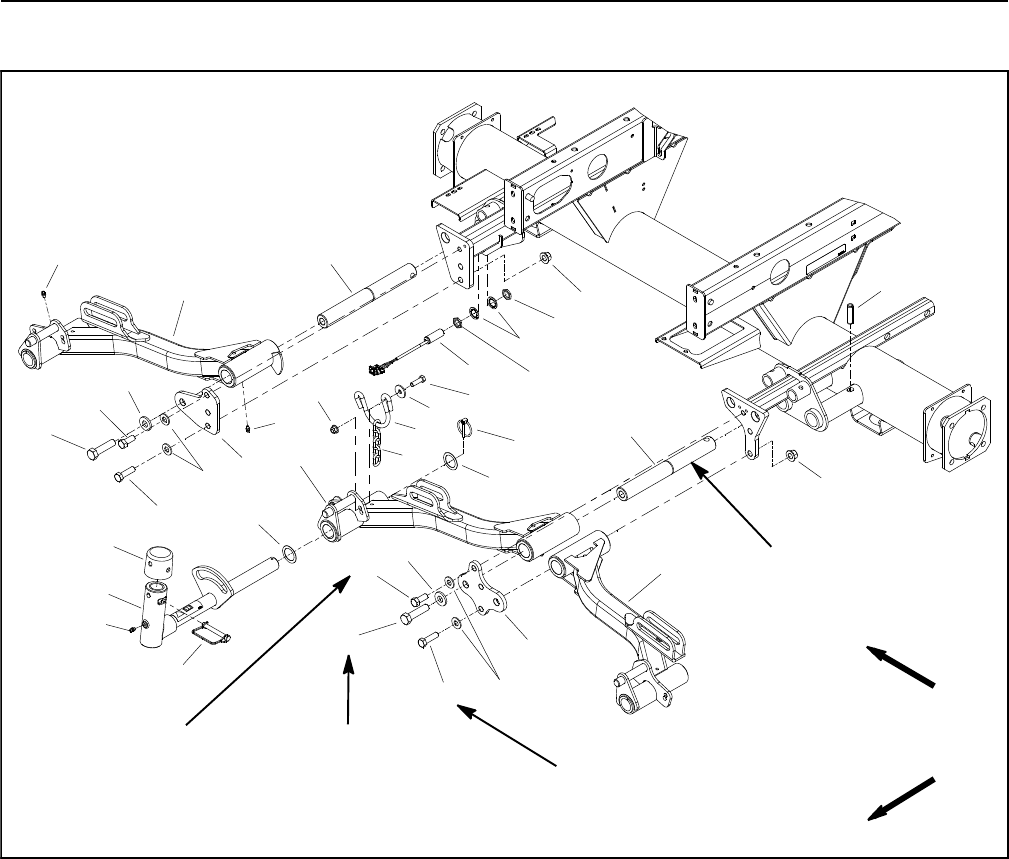
Reelmaster 5010- HPage 6 - 24Chassis
Front Lift Arms
1. #1 lift arm
2. #4 lift arm
3. #5 lift arm
4. Lift arm pivot shaft (3 used)
5. Roll pin (3 used)
6. Lock nut (4 used)
7. Cap screw (4 used)
8. Bridge plate
9. Cap screw (1 used per lift arm)
10. Chain hoop (3 used)
11. Washer (2 used per chain hoop)
12. Cap screw (2 used per chain hoop)
13. Pivot yoke (3 used)
14. Lynch pin (3 used)
15. Thrust washer (2 used per yoke)
16. Grease fitting
17. Bridge plate
18. Snapper pin (1 used per lift arm)
19. Cap (1 used per lift arm)
20. Thrust washer (6 used)
21. Cap screw (2 used)
22. Chain (3 used)
23. Up limit switch
24. Flange nut (2 used per chain hoop)
25. Flat washer (1 used per lift arm)
26. Jam nut (2 used)
27. Lock washer (2 used)
Figure 20
FRONT
RIGHT
75 to 95 ft- lb
(102 to 128 N- m)
135 to 165 ft- lb
(184 to 223 N- m)
2
3
6
8
910
11
13
1
5
7
12
14
15
16
17
18
19
20
4
21
22
23
24
25 26
27
16
21 25
9
720
15
4
6
16
26
Threadlocker
Medium Strength
Threadlocker
Medium Strength
75 to 95 ft- lb
(102 to 128 N- m)
Threadlocker
Medium Strength
Lubricant
Antiseize
Removal (Fig. 20)
1. Park machine on a level surface, lower cutting units,
stop engine, engage parking brake and remove key
from the ignition switch.
2. Remove cutting unit from front lift arm to be removed.
3. Remove one retaining ring (item 3 in Fig. 21) and
thrust washer (item 4 in Fig. 21) from the cylinder slide
pin (item 5 in Fig. 21) that secures lift cylinder to lift arm.
Pull slide pin from the lift cylinder and lift arm. Locate and
retrieve second thrust washer.
4. Pivot lift cylinder rod end away from lift arm.
5. Remove lynch pin (item 14) and slide pivot yoke as-
sembly from lift arm. Locate and retrieve two (2) thrust
washers (item 15).
6. Remove fasteners that secure bridge plate (item 8 or
17) to machine.
7. Slide front lift arm from lift arm pivot shaft.
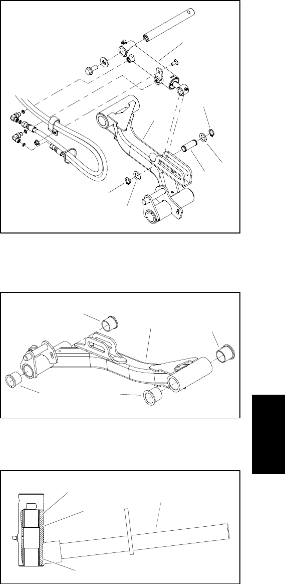
Reelmaster 5010- H Page 6 - 25 Chassis
8. Inspect bushings in lift arm and pivot yoke for wear
or damage. If necessary, replace bushings (Figs. 22 and
23).
A. Use bushing removal tool to extract bushings
from the lift arm or pivot yoke. Take care to not dam-
age the bore.
B. Clean the inside of the bore to remove any dirt or
foreign material.
C. Apply grease to the inside and outside of the new
bushings.
D. Use an arbor press to install the bushings into lift
arm or pivot yoke. Lift arm bushings should be
pressed until bushing flange is against lift arm bore.
The upper pivot yoke bushing should be pressed ful-
ly to the shoulder in the pivot yoke bore. The lower
pivot yoke bushing should be flush with the yoke
tube.
9. Check lift arm pivot shaft (item 4) for wear or dam-
age. If necessary, remove roll pin (item 5) that secures
pivot shaft to frame and remove pivot shaft. Discard re-
moved roll pin.
Installation (Fig. 20)
1. If lift arm pivot shaft (item 4) was removed from
frame, apply antiseize lubricant to portion of pivot shaft
that is in frame bore. Slide pivot shaft into frame and se-
cure with new roll pin (item 5).
2. Slide front lift arm onto pivot shaft.
3. Apply medium strength threadlocker to threads of
cap screws (items 7, 9 and 21) that secure bridge plate
(items 8 and 17). Secure lift arm to machine with bridge
plate. Torque cap screws that secure bridge plate to
torque values identified in Figure 20.
4. Position thrust washer (item 15) onto pivot yoke shaft
and then slide pivot yoke into lift arm bushings. Place
second thrust washer on pivot yoke shaft and secure
with lynch pin (item 14).
5. Align lift cylinder to lift arm mounting slot (Fig. 21).
Slide cylinder slide pin (item 5 in Fig. 21) with retaining
ring (item 3 in Fig. 21) and thrust washer (item 4 in Fig.
21) through the lift arm and lift cylinder. Install second
thrust washer on pin and secure with second retaining
ring.
6. Mount cutting unit to lift arm.
7. Lubricate grease fittings on lift arm, pivot yoke and lift
cylinder.
8. Check operation of lift arm up limit switch and adjust
if necessary (see Up Limit Switch in Components sec-
tion of Chapter 6 - Electrical System).
1. Lift arm (#4 shown)
2. Lift cylinder
3. Retaining ring
4. Thrust washer
5. Cylinder slide pin
Figure 21
4
3
2
3
4
5
1
1. Lift arm (#5 shown)
2. Lift arm bushing
3. Pivot yoke bushing
Figure 22
2
1
3
2
3
1. Pivot yoke
2. Upper bushing
3. Pivot yoke shoulder
4. Lower bushing
Figure 23
1
2
3
4
Chassis
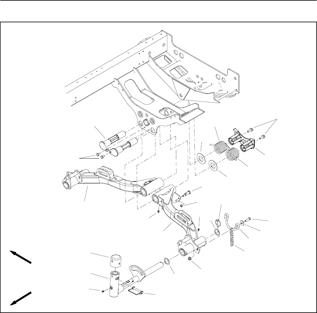
Reelmaster 5010- HPage 6 - 26Chassis
Rear Lift Arms
1. Housing
2. #2 lift arm
3. #3 lift arm
4. Washer (2 used per chain hoop)
5. Washer (2 used)
6. Flange head screw (2 used)
7. Shoulder stud (6 used)
8. Grease fitting
9. Pivot shaft (2 used)
10. Washer head screw (1 used per shaft)
11. Pivot yoke (2 used)
12. Lynch pin (2 used)
13. Thrust washer (2 used per yoke)
14. RH torsion spring
15. LH torsion spring
16. Snapper pin (1 used per yoke)
17. Cap (1 used per yoke)
18. Chain hoop (2 used)
19. Lock nut (6 used)
20. Cap screw (2 used per chain hoop)
21. Flange nut (2 used per chain hoop)
22. Chain (2 used)
Figure 24
FRONT
RIGHT
2
3
8
10
11
13
1
7
12
16
17
18
19
20
4
21
22
14
15
5
13
6
5
9
8
8
Removal (Fig. 24)
1. Park machine on a level surface, lower cutting units,
stop engine, engage parking brake and remove key
from the ignition switch.
2. Remove cutting unit from rear lift arm that is to be re-
moved.
3. Remove one retaining ring (item 3 in Fig. 25) and
thrust washer (item 4 in Fig. 25) from the cylinder pin
(item 5 in Fig. 25) that secures lift cylinder to lift arm. Pull
cylinder pin from the lift cylinder and lift arm. Locate and
retrieve second thrust washer.
4. Pivot lift cylinder rod end away from lift arm.
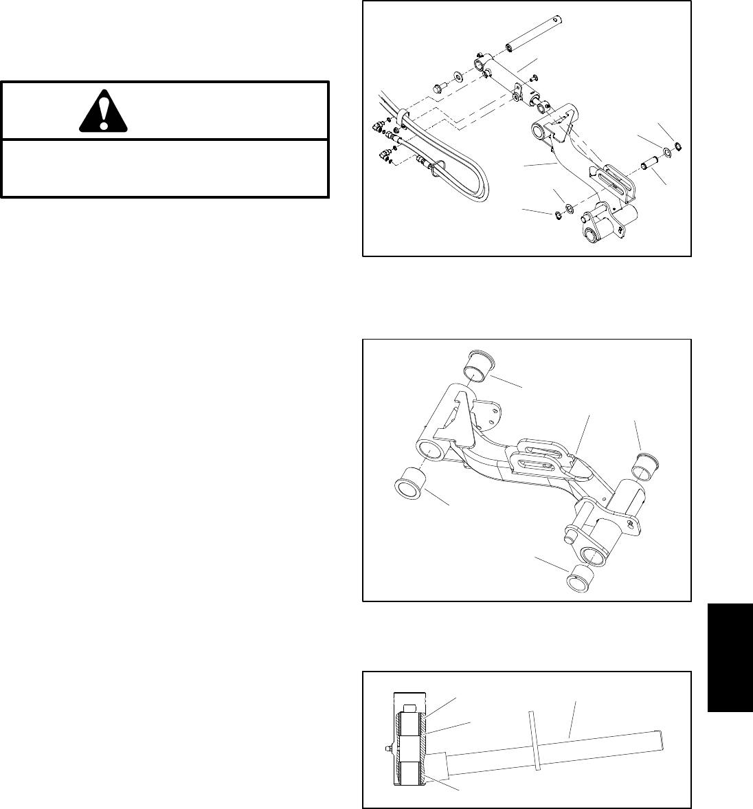
Reelmaster 5010- H Page 6 - 27 Chassis
5. Remove lynch pin (item 12) and rear thrust washer
(item 13) from rear of pivot yoke. Slide pivot yoke as-
sembly from lift arm. Locate and retrieve front thrust
washer (item 13).
CAUTION
Be careful when removing tension from the tor-
sion spring on the rear lift arms. The spring is un-
der heavy load and may cause personal injury.
6. Remove tension from both torsion springs (items 14
and 15) on rear of lift arm pivot shaft.
A. Note on which shoulder stud (item 7) the torsion
spring end is attached for assembly purposes.
B. Insert nut driver or small piece of pipe onto the
end of the torsion spring that is secured to the shoul-
der stud.
C. Push down and rearward on the spring end to un-
hook the spring from the shouldered stud (item 7).
7. Remove two (2) flange head screws (item 6) that se-
cure housing (item 1) to machine. Remove housing, tor-
sion springs (items 14 and 15) and two (2) washers (item
5).
8. Remove washer head screw (item 10) that secures
pivot shaft (item 9) to frame.
9. Support rear lift arm to prevent it from falling. Slide
pivot shaft from frame and lift arm. Remove rear lift arm.
10.Inspect pivot shaft and replace if worn or damaged.
11.Inspect bushings in lift arm and pivot yoke for wear
or damage. If necessary, replace bushings (Figs. 26 and
27).
A. Use bushing removal tool to extract both bush-
ings from the lift arm or pivot yoke. Take care to not
damage the bore.
B. Clean the inside of the bore to remove any dirt or
foreign material.
C. Apply grease to the inside and outside of the new
bushings.
D. Use an arbor press to install the bushings into lift
arm or pivot yoke. Lift arm bushings should be
pressed until bushing flange is against lift arm bore.
The upper pivot yoke bushing should be pressed ful-
ly to the shoulder in the pivot yoke bore. The lower
pivot yoke bushing should be flush with the yoke
tube.
Figure 25
4
3
2
3
4
5
1
1. Lift arm (#2 shown)
2. Lift cylinder
3. Retaining ring
4. Thrust washer
5. Cylinder pin
1. Rear lift arm (#2 shown)
2. Pivot yoke bushing
3. Lift arm bushing
Figure 26
2
1
3
2
3
1. Pivot yoke
2. Upper bushing
3. Pivot yoke shoulder
4. Lower bushing
Figure 27
1
2
3
4
Chassis
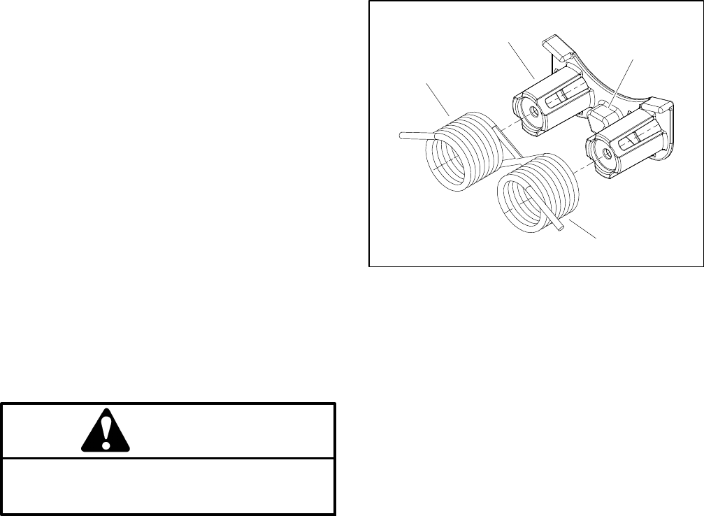
Reelmaster 5010- HPage 6 - 28Chassis
Installation (Fig. 24)
1. Position rear lift arm to frame and slide pivot shaft
through frame bosses and lift arm. Secure shaft with
washer head screw (item 10).
2. Place washer (item 5) over rear of each pivot shaft.
3. Place torsions springs (items 14 and 15) onto hous-
ing (item 1). Position long leg of springs forward and
pointing out from top of spring. Short leg of springs
should be against stop on housing (Fig. 28).
4. Position housing (item 1) to lift arm pivot shafts and
secure with two (2) flange head screws (item 6). Make
sure that washers (item 5) remain on ends of pivot shafts
and short end of torsion springs are against stop on
housing.
5. Align lift cylinder rod end to lift arm mounting slot.
Slide cylinder pin (item 5 in Fig. 25) with retaining ring
(item 3 in Fig. 25) and thrust washer (item 4 in Fig. 25)
through the lift cylinder and lift arm. Install second thrust
washer on pin and secure with second retaining ring.
CAUTION
Be careful when applying tension to the torsion
spring on the rear lift arms. The spring is under
heavy load and may cause personal injury.
6. Apply tension to torsion springs.
A. Insert nut driver or small piece of pipe onto the
long leg of the torsion spring on the rear of the lift arm
pivot pin.
B. Push down and forward on the spring end to hook
the spring to the stop bolt on the lift arm.
7. Mount cutting unit to lift arm.
8. Lubricate grease fittings on lift arm, pivot yoke and lift
cylinder.
1. Housing
2. Housing stop
3. RH torsion spring
4. LH torsion spring
Figure 28
1
2
3
4

Reelmaster 5010- H Page 6 - 29 Chassis
This page is intentionally blank.
Chassis
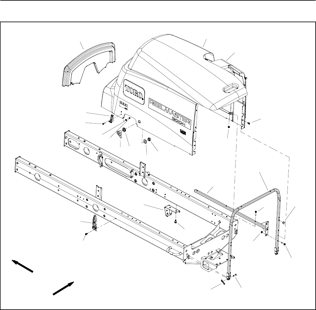
Reelmaster 5010- HPage 6 - 30Chassis
Hood
1. Sealed foam
2. Hood saddle
3. Hood
4. Catch (2 used)
5. Rubber latch (2 used)
6. Tube
7. Bow tie pin (2 used)
8. Deflector bracket (2 used)
9. Tube (2 used)
10. Washer head screw (8 used)
11. Flange head screw (10 used)
12. Flange nut (10 used)
13. Washer head screw (4 used)
14. Flat washer (4 used)
15. Lock nut (4 used)
16. Yoke pin (2 used)
17. Rubber bumper (2 used)
18. Latch
19. Washer head screw (4 used)
20. Grommet
21. Hex nut
22. Spacer
Figure 29
23
6
8
9
10
11
13
1
5
7
12
14 15
16
17
18
19
20
4
21
22
11
10
12
FRONT
RIGHT

Reelmaster 5010- H Page 6 - 31 Chassis
Removal (Fig. 29)
1. Park the machine on a level surface, lower the cut-
ting units and stop the engine. Remove the key from the
ignition switch.
2. Unlatch hood.
3. Remove bow tie pin (item 7) and yoke pin (item 16)
to allow hood removal.
4. Lift hood assembly from machine.
5. Remove hood components as necessary using Fig-
ure29asaguide.
6. Check condition of all seals on hood. Replace dam-
aged or missing seals.
Installation (Fig. 29)
1. Install all removed hood components using Figure
29 as a guide.
2. Position hood assembly to machine and slide tube
ends onto frame brackets.
3. Install yoke pin (item 16) and secure with bow tie pin
(item 7).
4. Latch hood.
Chassis
Reelmaster 5010- HPage 6 - 32Chassis
This page is intentionally blank.

Reelmaster 5010- H Cutting Units
Page 7 - 1
Chapter 7
Cutting Units
Table of Contents
SPECIFICATIONS 2............................
GENERAL INFORMATION 3.....................
Cutting Unit Operator’s Manual 3...............
48 VDC Battery Disconnect 3..................
SPECIAL TOOLS 4.............................
FACTORS THAT CAN AFFECT CUTTING
PERFORMANCE 8............................
SET UP AND ADJUSTMENTS 12.................
Characteristics 12.............................
Leveling Rear Roller 13........................
SERVICE AND REPAIRS 14.....................
Cutting Reel Motor 14.........................
Backlapping 15...............................
Bedbar Assembly 16..........................
Bedknife Replacement and Grinding 18..........
Bedbar Adjuster Service 20....................
Cutting Reel Assembly Removal and Installation 22
Reel Assembly Removal 22..................
Reel Assembly Installation 24................
Cutting Reel Assembly Service 26..............
Preparing Reel for Grinding 28.................
Front Roller 30...............................
Rear Roller 31................................
Roller Service 32.............................
Rear Roller Brush (Optional) 34.................
Rear Roller Brush Drive System (Optional) 36....
Cutting
Units
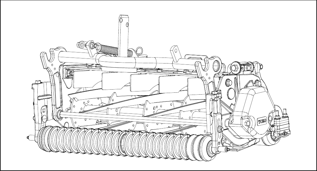
Reelmaster 5010- H
Cutting Units Page 7 - 2
Specifications
Figure 1
Frame Construction: Precision machined die cast alu-
minum cross member with two (2) bolt- on aluminum
side plates.
Reel Construction: Reels are 22 inches (55.9 cm.) in
length and are available in 5 inch (12.7 cm) and 7 inch
(17.8 cm) diameters. High strength, low alloy steel
blades are thru hardened and impact resistant. 5 inch
and7inchreelsareavailableinboth8and11bladecon-
figurations.
Reel Bearings: Two (2) sealed, stainless steel ball
bearings support the reel shaft with inboard spacer for
protection.
Reel Drive: The reel weldment shaft is a 1 5/16 inch
(33.3 mm) diameter tube with LH and RH drive inserts
threaded into both ends. The drive inserts for 5 inch re-
els have an internal eight (8) tooth spline. The drive in-
serts for 7 inch reels have an internal nine (9) tooth
spline.
Height- of- Cut (HOC): Cutting height is adjusted on
the front roller by two (2) vertical screws. Effective HOC
may vary depending on turf conditions, type of bedknife,
roller type and installed attachments.
Bedknife: Replaceable, tool steel EdgeMaxTM bedknife
is fastened to a machined cast iron bedbar with eight (8)
screws. Optional bedknives are available.
Bedknife Adjustment: Dual screw assemblies allow
for precise bedknife adjustment. Adjustment detents
correspond to bedknife movement for each indexed po-
sition as follows:
0.0007 inch (0.018 mm) for 5 inch reel
0.0009 inch (0.022 mm) for 7 inch reel
Front and Rear Rollers: Greaseable through- shaft
front and rear rollers are used with these cutting units.
All rollers use the same heavy duty, stainless steel ball
bearings and seal package.
Cutting Unit Weight (without end weight):
8 Blade, 5 inch reel 90 lb. (41 kg)
11 Blade, 5 inch reel 93 lb. (42 kg)
8 Blade, 7 inch reel 118lb.(54kg)
11 Blade, 7 inch reel 121lb.(55kg)
Options: Refer to Cutting Unit Operator’s Manual for
available options for your Reelmaster cutting unit.
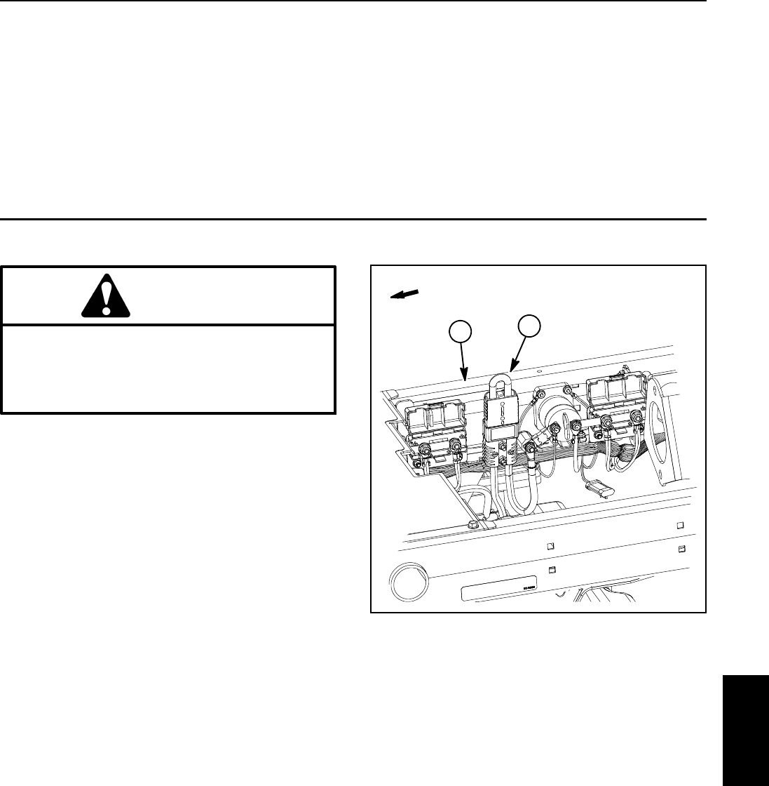
Reelmaster 5010- H Cutting Units
Page 7 - 3
General Information
Cutting Unit Operator’s Manual
The Cutting Unit Operator’s Manual provides informa-
tion regarding the operation, general maintenance and
maintenance intervals for the cutting units on your Reel-
master machine. Additionally, if optional kits have been
installed on the cutting units (e.g. groomer, rear roller
brush), the installation instructions for the kit includes
set- up and operation information. Refer to those publi-
cations for additional information when servicing the
cutting units.
48 VDC Battery Disconnect
CAUTION
Before installing, removing or servicing compo-
nents in the 48 VDC system (e.g. cutting unit mo-
tors, motor/generator), separate the 48 VDC bat-
tery disconnect. This will prevent unexpected
operation of 48 VDC system components.
The 48 VDC battery disconnect is attached to the right
frame rail under the operator seat (Fig. 2). Unplug the
disconnect to make sure that 48 VDC components do
not operate unexpectedly. Apply dielectric grease to the
contact surfaces of the battery disconnect and plug the
battery disconnect back in after service to the 48 VDC
system is completed.
1. RH frame rail 2. 48V battery disconnect
Figure 2
2
1
FRONT
Cutting
Units
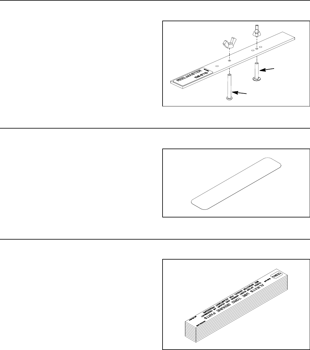
Reelmaster 5010- H
Cutting Units Page 7 - 4
Special Tools
Order special tools for your Reelmaster from your Toro
Distributor. Some tools may have been supplied with
yourmachineorareavailableasToroparts.
Gauge Bar Assembly
Toro Part Number: 108- 6715
Use gauge bar to verify height- of- cut adjustment. Also
used for adjustment of optional groomer.
Figure 3
Used for Height- of-
Cut adjustment
groomer
adjustment
Used for
Cutting Reel Shim
Toro Part Number: 125- 5611
The cutting reel shim (0.002”) is used to help parallel the
bedknife and cutting reel.
Figure 4
Cutting Performance Paper
Toro Part Number: 125- 5610
Cutting performance paper is used to test the cutting
reel performance after adjusting the reel to bedknife
clearance. 10 packs (30 strips per pack) of cutting per-
formance paper are included in this part number.
Figure 5
Reelmaster 5010- H Cutting Units
Page 7 - 5
Bedknife Screw Tool
Toro Part Number: TOR510880
This screwdriver- type bit is made to fit Toro bedknife at-
tachingscrews.Usethisbitwithatorquewrenchtose-
cure the bedknife to the bedbar.
IMPORTANT: To prevent damage to the bedbar, DO
NOT use an air or manual impact wrench with this
tool.
Figure 6
Handle Assembly
Toro Part Number: 29- 9100
For applying lapping compound to cutting units while
keeping hands a safe distance from the rotating reel.
Components for the handle assembly are available indi-
vidually as follows:
Brush 36- 4310
Handle 29- 9080
Handle cap 2410- 18 Figure 7
Cutting Unit Kickstand
Toro Part Number: 119- 8010- 03
The cutting unit kickstand is used to prop up the rear of
the cutting unit during service. Use of this tool stabilizes
the cutting unit and prevents the bedbar adjusting
screws from resting on the work surface.
Figure 8
Cutting
Units
Reelmaster 5010- H
Cutting Units Page 7 - 6
Spline Insert Tool
Toro Part Number: TOR4112 (8toothfor5inchreels)
TOR4074 (9toothfor7inchreels)
Use spline insert tool for rotating cutting reel when motor
is removed. Also use this tool for installation of threaded
inserts into cutting reel shaft.
Figure 9
Rear Roller Bearing and Seal Installation Tools
Toro Part Number: 115- 0803
This tool kit is used to assemble the cutting unit rollers.
Tools in this kit are also available individually as follows:
115- 0852 Inner Seal Tool
115- 0853 Bearing/Outer Seal Tool
107- 8133 Bearing Installation Washer
Figure 10
Inner Seal
Tool
Bearing/Outer Seal
Bearing Installation
Washer
Tool
Plastic Plug
Toro Part Number: 2410- 30 (for5inchreels)
94- 2703 (for7inchreels)
This cap is used for placement into the cutting unit side
plate when the cutting reel motor is removed. It prevents
dirt and debris from entering the cutting reel bearing
area.
Figure 11
Reelmaster 5010- H Cutting Units
Page 7 - 7
Pulley Alignment Tool
Toro Part Number: 114- 5446
Use pulley alignment tool to verify alignment of groomer
and/or rear roller brush drive and driven pulleys.
Figure 12
Diameter/Circumference Measuring Tape
Toro Part Number: TOR6023
Spring steel measuring tape for accurately measuring
the circumference and outside diameter of cutting reel
and other spherical components. Tape calibration is in
fixed inch readings (no adjustments).
Figure 13
Turf Evaluator Tool
Toro Model Number: 04399
Many turf discrepancies are subtle and require closer
examination. In these instances, the Turf Evaluator
grass viewing tool is helpful. It can assist turf managers
and service technicians in determining causes for poor
reel mower performance and in comparing the effective
height- of- cut of one mowed surface to another. This
toolshouldbeusedwiththeToroGuidetoEvaluation
Reel Mower Performance and Using the TurfEvaluator
(Toro part no. 97931SL)
Figure 14
Cutting
Units

Reelmaster 5010- H
Cutting Units Page 7 - 8
Factors That Can Affect Cutting Performance
There are a number of factors that can contribute to un-
satisfactory quality of cut, some of which may be turf
conditions. Turf conditions such as excessive thatch,
“sponginess” or attempting to cut off too much grass
height may not always be overcome by adjusting the
cutting unit. It is important to remember that the lower
the height- of- cut, the more critical these factors are.
Refer to the Cutting Unit’s Operator’s Manual for de-
tailed cutting unit adjustment procedures. For cutting
unit repair information, refer to the Service and Repairs
section of this chapter.
NOTE: For additional information regarding cutting unit
troubleshooting, see Aftercut Appearance Trouble-
shooting Aid (Toro part no. 00076SL).
Factor Possible Problem/Correction
Tire pressure Check tire pressure of all traction unit tires. Adjust tire
pressure as necessary.
Engine speed For best cutting performance and appearance, engine
should be run at maximum governed speed during
machine operation (use InfoCenter Display to check
engine speed).
Reel speed All cutting reels must rotate at the same speed (within
100 rpm) (use InfoCenter Display to check reel speed).
All cutting units must have equal bedknife to reel and
height- of- cut adjustments.
Make sure that reel speed selection is correct (use
InfoCenter Display to check and adjust reel speed).
Reel bearing condition Check reel bearings for wear and replace if necessary.
See Reel Assembly in the Service and Repairs section
of this chapter.
Bedknife to reel adjustment Check bedknife to reel contact daily. The bedknife
must have light contact across the entire reel. No
contact will dull the cutting edges. Excessive contact
accelerates wear of both edges. Quality of cut is
adversely affected by both conditions (see Bedknife to
Reel Adjustment in the Cutting Unit Operator’s
Manual).

Reelmaster 5010- H Cutting Units
Page 7 - 9
Factor Possible Problem/Correction
Reel and bedknife sharpness
NOTE: After grinding the reel and/or bedknife, check
the reel to bedknife contact again after cutting two (2)
fairways. During this initial use, any burrs will be
removed from reel and bedknife which may create
improper reel to bedknife clearance and thus
accelerate wear. This practice of re- checking the reel
to bedknife contact after grinding will extend the
longevity of the sharpness of the edge of the reel and
the bedknife.
A reel and/or bedknife that has rounded cutting edges
or “rifling” (grooved or wavy appearance) cannot be
corrected by tightening the bedknife to reel contact.
Grind cutting reel to remove taper and/or rifling. Grind
bedknife to sharpen and/or remove rifling.
The most common cause of rifling is bedknife to reel
contact that is too tight.
Dull cutting edges must be corrected by grinding the
bedknife and cutting reel (see Preparing Reel for
Grinding in the Service and Repairs section of this
chapter).
A new bedknife must be ground flat (within 0.002”)
after installation to the bedbar. Backlapping may
be required to properly mate the reel and bedknife
after installation into the cutting unit.
NOTE: On cutting units equipped with optional
bedknives, slightly dull cutting edges may be corrected
by backlapping (see Backlapping in the Service and
Repairs section of this chapter).
Rear roller adjustment Adjust the rear roller brackets to correct position
depending on the height- of- cut range and
aggressiveness of cut that is desired.
See Rear Roller Adjustment in the Cutting Unit
Operator’s Manual.
Height- of- cut “Effective” or actual height- of- cut depends on the
cutting unit weight and turf conditions. Effective
height- of- cut will be different from the bench set
height- of- cut.
See Height- of- Cut Adjustment in the Cutting Unit
Operator’s Manual.
Proper bedknife selection for height- of- cut desired If the bedknife is incorrect for effective height- of- cut,
poor quality of cut will result.
See Cutting Unit Operator’s Manual for bedknife
options.
Stability of bedbar Make sure bedbar pivot bolts are seated securely.
Check condition of the bushings in the side plates.
See Bedbar Removal and Installation in the Service
and Repairs section of this chapter.
Number of reel blades Use correct number of reel blades for clip frequency
and optimum height- of- cut range.
Refer to Clip Chart in Traction Unit Operator’s Manual.
Cutting
Units

Reelmaster 5010- H
Cutting Units Page 7 - 10
Factor Possible Problem/Correction
Cutting unit alignment and carrier frame ground
following
Check carrier frames and lift arms for damage, binding
conditions or bushing wear. Repair if necessary.
Roller condition and roller type Make sure rollers rotate freely. Repair roller bearings
as necessary.
See Roller Service in the Service and Repairs section
of this chapter.
Refer to Cutting Unit Operator’s Manual for roller
options.
Turf compensation spring adjustment Refer to Traction Unit Operator’s Manual for
adjustment procedure.
Rear lift arm counterbalance spring adjustment Refer to Traction Unit Operator’s Manual for
adjustment procedure.
Cutting unit accessories A variety of cutting unit accessories are available that
can be used to enhance aftercut appearance. Refer to
Cutting Unit Operator’s Manual for a listing of available
accessories.

Reelmaster 5010- H Cutting Units
Page 7 - 11
This page is intentionally blank.
Cutting
Units

Reelmaster 5010- H
Cutting Units Page 7 - 12
Set Up and Adjustments
Characteristics
CAUTION
Never install or work on the cutting units or lift
arms with the engine running. Always stop en-
gine and remove key first.
Also, before installing, removing or working on
the cutting units, disconnect the cutting units
from the electrical power supply by separating
the 48 VDC battery disconnect (see 48 VDC Bat-
tery Disconnect in the General Information sec-
tion of this chapter).
The dual knob bedknife- to- reel adjustment system in-
corporated in this cutting unit simplifies the adjustment
procedure needed to deliver optimum mowing perfor-
mance. The precise adjustment possible with this de-
sign gives the necessary control to provide a continual
self- sharpening action. This feature maintains sharp
cutting edges, assures good quality of cut and greatly
reduces the need for routine backlapping.
In addition, the rear roller positioning system allows for
various height-of-cut ranges and aggressiveness of cut
selections.
If a cutting unit is determined to be out of adjustment,
complete the following procedures in the specified order
to adjust the cutting unit properly.
1. Adjust the bedknife parallel to the reel.
2. Determine desired height- of- cut range and install
rear roller mounting shim(s) accordingly.
3. Adjust the height- of- cut.
See Cutting Unit Operator’s Manual for cutting unit ad-
justment procedures for your Reelmaster.
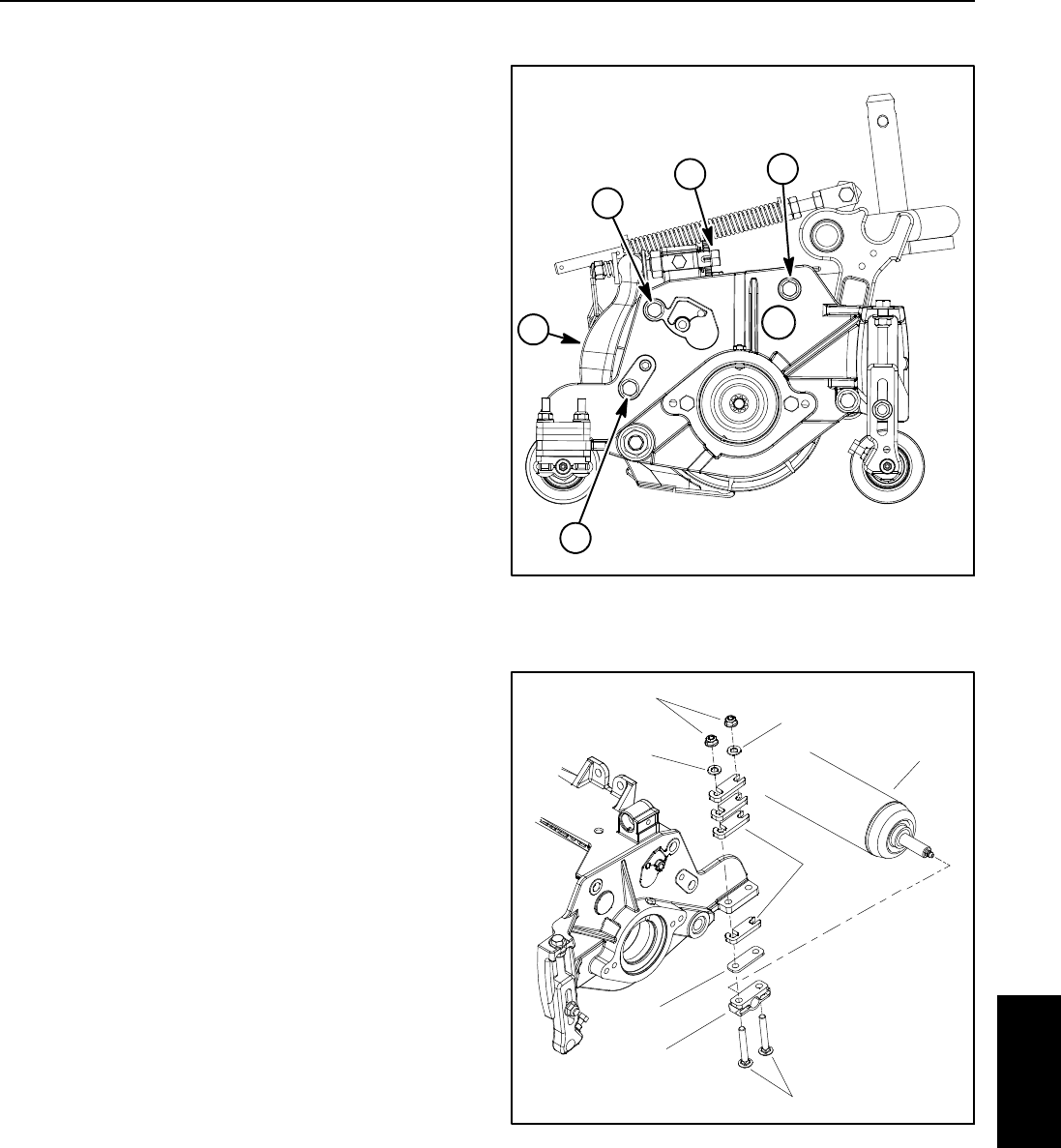
Reelmaster 5010- H Cutting Units
Page 7 - 13
Leveling Rear Roller
The precision machined components of the cutting unit
frame keep the rear roller and cutting reel in alignment
(parallel). If the side plates are disassembled or as the
cutting reel wears, a limited amount of side plate adjust-
ment is possible to make sure that the cutting unit is
properly aligned.
1. Place the assembled cutting unit on a surface plate.
2. Make sure that bedknife is properly adjusted to cut-
ting reel.
3. Using the surface plate, check if rear roller is level to
cutting reel by using a 0.005” (0.13 mm) shim at each
end of rear roller. If the shim will pass under the roller at
one end but not the other, a frame adjustment should be
made.
NOTE: Cutting units with 5” diameter reel use two (2)
shoulder bolts to secure side plates to frame. Cutting
units with 7” diameter reel use three (3) shoulder bolts
to secure side plates to frame.
4. Loosen, but do not remove, shoulder bolts that se-
curethesideplatetotheframeoppositethesidethatis
not level (Fig. 15).
5. Adjust the position of the side plate to parallel the
rear roller and cutting reel. Then, tighten the shoulder
bolts to a torque from 27 to 33 ft- lb (37 to 44 N- m).
6. After tightening the side plate, recheck the rear roller.
If necessary, loosen and adjust second side plate.
7. If rear roller is still not level after adjusting both side
plates, check to see if cutting reel is tapered (see Pre-
paring Reel for Grinding in the Service and Repairs sec-
tion of this chapter). If cutting reel is not tapered and rear
roller is not level, a 0.010” shim (part number 107- 4001)
is available to allow additional rear roller adjustment.
The shim would be used on one side of the rear roller
and should be installed between the rear roller bracket
and roller shim (Fig. 16).
8. After leveling rear roller, complete cutting unit set- up
and adjustment sequence.
1. Bedbar
2. Bedbar adjuster
3. Shoulder bolt
Figure 15
Cutting Unit with 7” Reel Shown
2
3
1
3
3
1. Rear roller assembly
2. Rear roller bracket
3. Carriage screw
4. Flange nut
5. Washer
6. Roller shim
7. 0.010” shim (if needed)
Figure 16
1
2
3
4
5
6
5
7
Cutting
Units
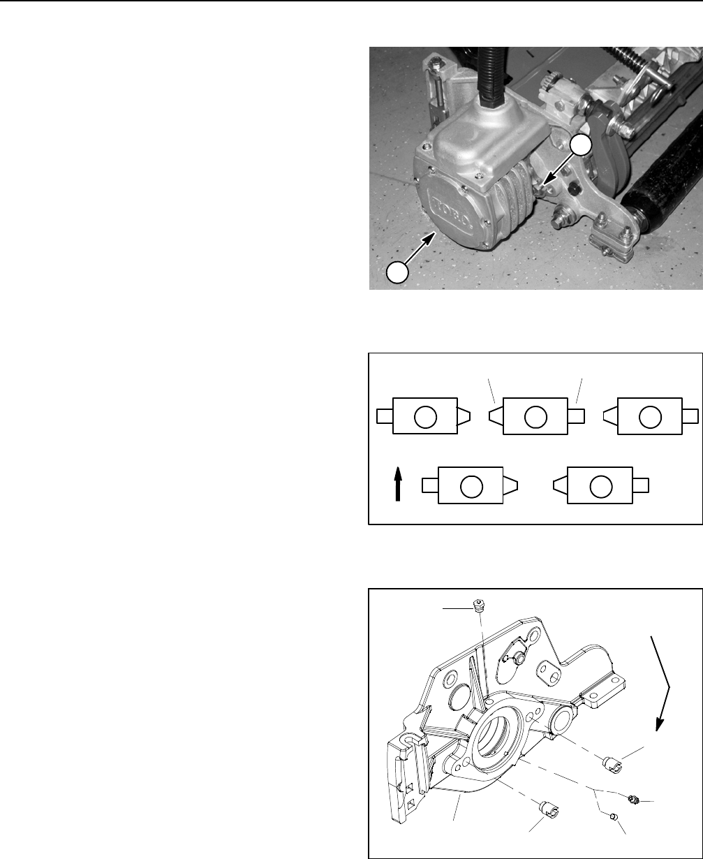
Reelmaster 5010- H
Cutting Units Page 7 - 14
Service and Repairs
Cutting Reel Motor
NOTE: If electrical problems exist with a cutting reel
motor, a fault should have occurred that would be indi-
cated by a fault code on the InfoCenter Display. Before
considering that reel motor service work is necessary,
check for any existing fault codes that indicate problems
withareelmotor.
IMPORTANT: When performing service or mainte-
nance on the cutting reel motors, take care to not
damage the motors or electrical connections.
For information on removal, installation and service of
the cutting unit motors, see Cutting Reel Motor and Cut-
ting Reel Motor Service in the Service and Repairs sec-
tion of Chapter 5 - Electrical System.
The cutting unit side plates (Fig. 19) have threaded in-
serts at the locations used for the cap screws that secure
the reel motor. Check the condition of the threaded in-
serts whenever the cutting reel motor is removed and re-
place inserts if damage is found. Inserts should be
torqued from 35 to 40 ft- lb (48 to 54 N- m) during instal-
lation.
For proper lubrication of the reel motor splines, a grease
fitting (item 3 in Fig. 19) must be installed in the cutting
unit side plate on the reel motor side of the cutting unit.
On the non- drive side plate, a set screw (item 4 in Fig.
19) should be installed so that it is flush with the side
plate surface.
NOTE: RefertoFigure18forcorrectplacementofcut-
ting unit reel motors and weights.
1. Cutting reel motor 2. Cap screw (2 used)
Figure 17
1
2
1. Reel motor location 2. Weight location
Figure 18
FRONT
4 1 5
32
12
1. Side plate (LH shown)
2. Threaded insert
3. Grease fitting
4. Set screw
5. Relief fitting
Figure 19
2
3
1
5
4
2
35 to 40 ft- lb
(48to54N-m)
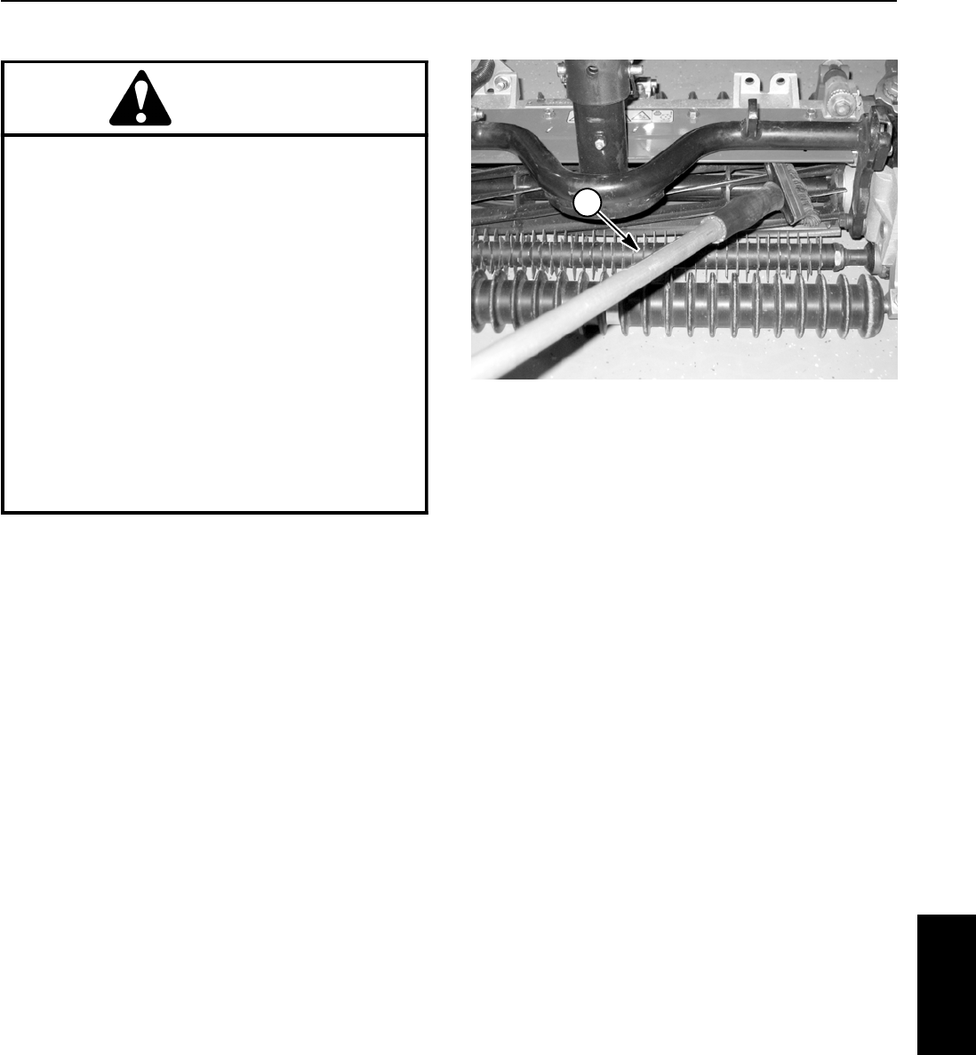
Reelmaster 5010- H Cutting Units
Page 7 - 15
Backlapping
DANGER
TO AVOID PERSONAL INJURY OR DEATH:
DNever place hands or feet in the reel area
while the engine is running or if the 48 VDC bat-
tery pack is connected. Disconnect the cutting
units from the electrical power supply by sepa-
rating the 48 VDC battery disconnect (see 48 VDC
Battery Disconnect in the General Information
section of this chapter).
DWhile backlapping, the reels may stall and
then restart.
DDo not attempt to restart reels by hand or foot.
DDo not adjust reels while the engine is
running or if the 48 VDC battery pack is connect-
ed.
DIf a reel stalls, stop engine and separate the 48
VDC battery disconnect before attempting to
clear the reel.
NOTE: Instructions and procedures on backlapping
are available in the Traction Unit Operator’s Manual and
theToroGeneralServiceTrainingBook,ReelMower
Basics (part no. 09168SL).
1. Long handle brush
Figure 20
1
Cutting
Units
Reelmaster 5010- H
Cutting Units Page 7 - 16
Bedbar Assembly
1. Bedbar assembly
2. Flange bushing (2 used)
3. Plastic washer (4 used)
4. Metal washer (2 used)
5. Bedbar pivot bolt (2 used)
6. Lock nut (2 used)
7. Lock nut (2 used)
8. Compression spring (2 used)
9. Washer (2 used)
10. Bedbar adjuster screw (2 used)
11. Cutting unit frame
12. RH side plate
13. Cutting reel assembly
14. LH side plate
Figure 21
7” CUTTING REEL SHOWN
FRONT
RIGHT
Antiseize
Lubricant
23
6
8
9
10
11
13
1
5
7
12
14
4
3
Bedbar Removal (Fig. 21)
1. Position machine on a clean and level surface, lower
cutting units, stop engine, engage parking brake and re-
move key from the ignition switch.
2. To prevent unexpected reel motor operation, discon-
nect motors from the electrical power supply by unplug-
ging the 48 VDC battery disconnect (see 48 VDC
Battery Disconnect in the General Information section of
this chapter).
3. Remove the cutting unit from the machine. Use the
cutting unit kickstand to support the cutting unit (see
Special Tools in this chapter).
4. Loosen the lock nuts (item 7) on the end of each bed-
bar adjuster assembly until washer (item 9) is loose.
5. Loosen the lock nuts (item 6) on each bedbar pivot
bolt (item 5).
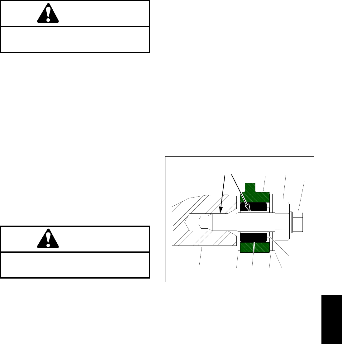
Reelmaster 5010- H Cutting Units
Page 7 - 17
6. Remove two (2) bedbar pivot bolts (item 5), two (2)
metal washers (item 4) and four (4) plastic washers
(item 3) from the cutting unit side plates.
CAUTION
Contact with the reel, bedknife or other cutting
unit parts can result in personal injury. Use
heavy gloves when handling the bedbar.
7. Remove bedbar assembly from cutting unit.
8. Inspect flange bushings (item 2) and rubber bush-
ings in side plates for wear or damage. Remove bush-
ings and replace if necessary.
Bedbar Installation (Fig. 21)
1. If rubber bushing was removed from either cutting
unit side plate, install a new bushing. The bushing
should be installed flush with the inside of the side plate
(Fig. 22).
2. If removed, install the flange bushings (item 2) with
flange facing outward. Apply antiseize lubricant to inside
of flange bushing.
3. Apply antiseize lubricant to the bedbar threads and
the shoulder area of each bedbar pivot bolt.
4. Slide one metal washer (item 4) and one plastic
washer (item 3) onto each bedbar pivot bolt.
CAUTION
Contact with the reel, bedknife or other cutting
unit parts can result in personal injury. Use
heavy gloves when handling the bedbar.
5. Position bedbar into cutting unit. Make sure that the
top of each bedbar arm is between washer (item 9) and
adjuster screw flange (item 10).
6. Position a plastic washer (item 3) between bedbar
and each cutting unit side plate (Fig. 22).
7. Install the bedbar pivot bolt assemblies. Make sure
that plastic washers are not caught on the threads of the
pivot bolts. Tighten each bedbar pivot bolt from 27 to 33
ft- lbs (37 to 44 N- m).
8. Tighten both lock nuts (item 6) until outside metal
washer just stops rotating. Do not over tighten the lock
nuts as this can distort the side plates and affect reel
bearing adjustment. The plastic washer between the
bedbar and side plate should be loose.
9. Tighten the lock nut (item 7) on each bedbar adjuster
assembly until the adjuster spring is fully compressed,
then loosen lock nut 1/2 turn.
10.Adjust cutting unit (see Cutting Unit Operator’s
Manual).
11. Install cutting unit to machine.
12.Plug the 48 VDC battery disconnect back in before
operating the machine.
1. Cutting unit sideplate
2. Rubber bushing
3. Flange bushing
4. Washer (plastic)
5. Washer (metal)
6. Bedbar
7. Bedbar pivot bolt
8. Lock nut
Figure 22
1
2
3
4
6
7
8
5
4
Antiseize
Lubricant
Cutting
Units
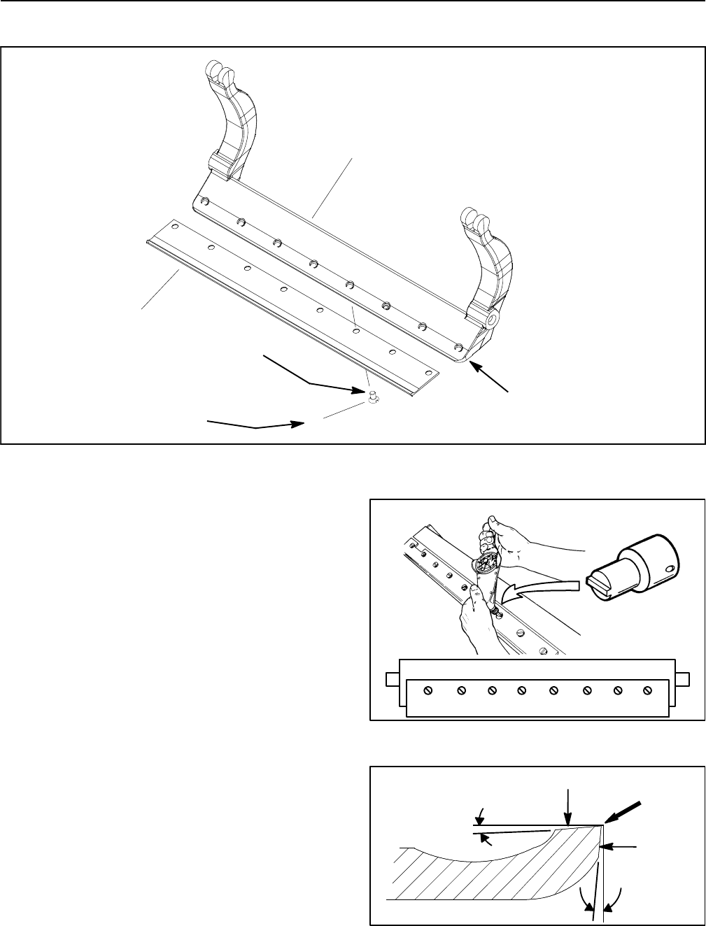
Reelmaster 5010- H
Cutting Units Page 7 - 18
Bedknife Replacement and Grinding
1. Screw (8 used) 2. Bedbar 3. Bedknife
Figure 23
v
1
2
3
Antiseize
Lubricant
200 to 250 in- lb
(23to28N-m)
Lightly Oil
Bedbar Surface
Bedknife Removal
1. Remove bedbar from cutting unit (see Bedbar As-
sembly in this section).
2. Remove screws from bedbar using a socket wrench
and bedknife screw tool (see Special Tools in this chap-
ter). Discard screws. Remove bedknife from the bedbar
(Fig. 23).
Bedknife Installation
1. Use scraper to remove all rust, scale and corrosion
from bedbar surface. Lightly oil bedbar surface before
installing bedknife.
2. Make sure that screw threads in bedbar
(5/16- 18UNC- 2A) are clean. Apply antiseize lubricant
to the threads of new screws. Take care to keep anti-
seize lubricant from taper on screw heads.
IMPORTANT: Do not use an impact wrench to tight-
en screws into the bedbar.
3. Use new screws to secure bedknife to bedbar. Install
all screws but do not tighten fully. Then, using a torque
wrench and bedknife screw tool, torque screws from
200 to 250 in- lb (23 to 28 N- m).Useatorquingpattern
working from the center toward each end of the bedknife
(Fig. 24).
Figure 24
12468357
Figure 25
Top Angle
Front Angle
To p F a c e
Front
Face
Remove
Burr
Reelmaster 5010- H Cutting Units
Page 7 - 19
4. After installing bedknife to bedbar, grind bedknife.
Bedknife Grinding
Since there can be variations in the mounting surface of
the bedbar, a new bedknife will not be perfectly flat after
it is installed to the bedbar. Because of this, it is neces-
sary to grind a new bedknife after installing it to the bed-
bar. Follow the existing angle that was ground into the
bedknife and grind only enough to make sure the top
surface of the bedknife is true (Fig. 25).
IMPORTANT: When grinding the bedknife, be care-
ful to not overheat the bedknife. Remove small
amounts of material with each pass of the grinder.
Also, clean and dress grinding stone often during
the grinding process.
1. Use Cutting Unit Operator’s Manual, Toro General
Service Training Book, Reel Mower Basics (part no.
09168SL) and grinder manufacturer’s instructions for
bedknife grinding information.
2. After grinding bedknife, check lead- in chamfer on
bedknife (see Cutting Unit Operator’s Manual).
3. After bedknife grinding is complete, install bedbar to
cutting unit (see Bedbar Assembly in this section).
NOTE: After grinding the reel and/or bedknife, check
the reel to bedknife contact again after cutting two (2)
fairways. During this initial use, any burrs will be re-
moved from reel and bedknife which may create improp-
er reel to bedknife clearance and thus accelerate wear.
This practice of re- checking the reel to bedknife contact
after grinding will extend the longevity of the sharpness
of the edge of the reel and the bedknife.
Bedknife Grinding Specifications (see Fig. 25)
Bedknife Top Angle 10o
Bedknife Front Angle 5o
Extended Bedknife Front Angle 10o
1. Bedknife 2. Lead- in chamfer
Figure 26
0.060”
(1.5 mm)
0.250”
(6.4 mm)
1
2
Cutting
Units
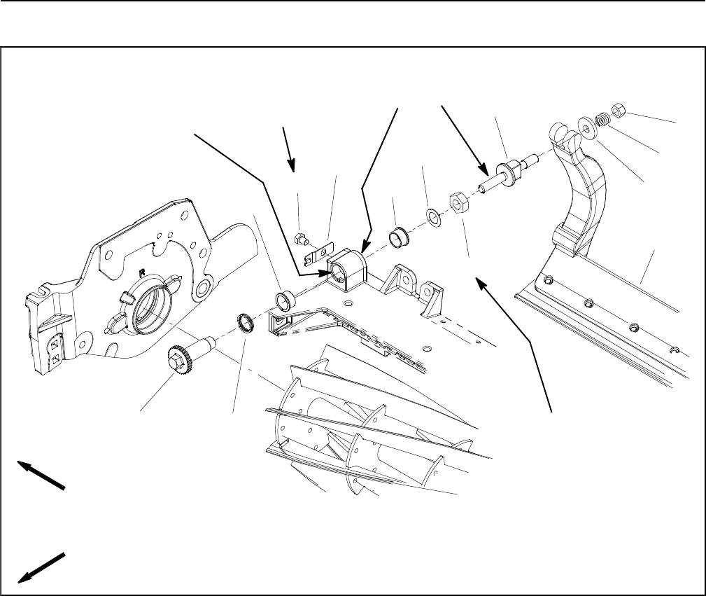
Reelmaster 5010- H
Cutting Units Page 7 - 20
Bedbar Adjuster Service
Figure 27
1. Bedbar assembly
2. Compression spring
3. Lock nut
4. Bedbar adjuster screw
5. Keyed flange bushing (2 used)
6. Cap screw
7. Detent
8. Flat washer
9. Lock nut
10. Bedbar adjuster shaft
11. Wave washer
12. Washer
FRONT
RIGHT
14 to 16 ft- lb
(19to21N-m)
Antiseize
Lubricant
1
2
11
3
4
5
6
78
9
10
12
5
15 to 20 ft- lb
(21to27N-m)
Antiseize
Lubricant

Reelmaster 5010- H Cutting Units
Page 7 - 21
Removal (Fig. 27)
1. Remove lock nut (item 3), compression spring (item
2) and washer (item 12) from bedbar adjuster screw
(item 4).
2. Remove bedbar (see Bedbar Assembly in this sec-
tion).
NOTE: Inside threads in bedbar adjuster shaft (item 10)
are left- hand threads.
3. Unscrew bedbar adjuster screw (item 4) from the
bedbar adjuster shaft (item 10).
4. Remove bedbar adjuster shaft (item 10) from cutting
unit frame:
A. Remove lock nut and flat washer from adjuster
shaft.
B. Slide adjuster shaft and wave washer from cut-
ting unit frame.
5. Inspect keyed flange bushings (item 5) in cutting unit
frame and remove if necessary.
6. If detent (item 7) is damaged, remove it from cutting
unit side plate by removing the cap screw (item 6).
Installation (Fig. 27)
1. If detent (item 7) was removed, secure detent to cut-
ting unit side plate with cap screw. Torque cap screw
from 14 to 16 ft- lb (19 to 21 N- m).
2. If keyed flange bushings (item 5) were removed from
cutting unit frame, apply antiseize lubrication to bushing
bore in cutting unit frame. Align key on bushing to slot in
frame and slide bushing into frame.
3. Install bedbar adjuster shaft (item 10) to cutting unit
frame:
A. Slide wave washer onto bedbar adjuster shaft
andthenslideadjustershaftintokeyedflangebush-
ing in cutting unit frame.
B. Secure adjuster shaft with flat washer and lock
nut. Tighten lock nut to shoulder of adjuster shaft and
then torque lock nut from 15 to 20 ft- lb (21 to 27
N-m).
NOTE: Inside threads in bedbar adjuster shaft (item 10)
are left- hand threads.
4. Apply antiseize lubricant to threads of bedbar adjust-
er screw (item 4) that fit into bedbar adjuster shaft (item
10). Thread bedbar adjuster screw into adjuster shaft.
5. Install bedbar (see Bedbar Assembly in this section).
6. Install washer (item 12), compression spring (item 2)
and lock nut (item 3) onto bedbar adjuster screw. Tight-
en the lock nut on each bedbar adjuster assembly until
the compression spring is fully compressed, then loosen
lock nut 1/2 turn.
7. Adjust cutting unit (see Cutting Unit Operator’s
Manual).
Cutting
Units
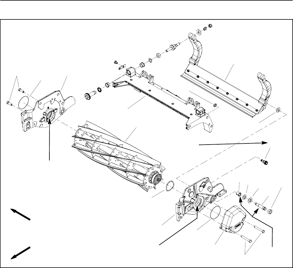
Reelmaster 5010- H
Cutting Units Page 7 - 22
Cutting Reel Assembly Removal and Installation
1. Bedbar assembly
2. Cutting unit frame
3. Flange bushing (2 used)
4. Plastic washer (4 used)
5. Metal washer (2 used)
6. Bedbar pivot bolt (2 used)
7. Lock nut (2 used)
8. RH side plate
9. LH side plate
10. Weight
11. Cap screw (2 used)
12. O- ring
13. Cutting reel assembly
14. Wire spring
15. Flange nut (3 used per side plate)
16. Shoulder bolt (3 used per side plate)
17. Cap screw (2 used)
18. O- ring
Figure 28
Antiseize
Lubricant
FRONT
RIGHT
7” CUTTING REEL SHOWN
2
3
6
8
9
10
11
13
1
57
12
14
15
16
17
18
4
4
27 to 33 ft- lb
(37to44N-m)
Antiseize
Lubricant
Antiseize
Lubricant
NOTE: This section provides the procedure for remov-
ing and installing the cutting reel assembly (cutting reel,
spline inserts, seals and bearings) from the cutting unit.
Refer to Reel Assembly Service later in this section for
information on replacing cutting reel seals and bearings.
NOTE: Removal of the cutting reel requires removal of
the left side plate (item 9) from the cutting unit frame.
The right side plate (item 8) does not have to be re-
moved from the frame.
Reel Assembly Removal (Fig. 28)
1. Position machine on a clean and level surface, lower
cutting units, stop engine, engage parking brake and re-
move key from the ignition switch.
2. To prevent unexpected reel motor operation, discon-
nect motors from the electrical power supply by unplug-
ging the 48 VDC battery disconnect (see 48 VDC
Battery Disconnect in the General Information section of
this chapter).
3. Remove the cutting unit from the machine and place
it on a flat work area.
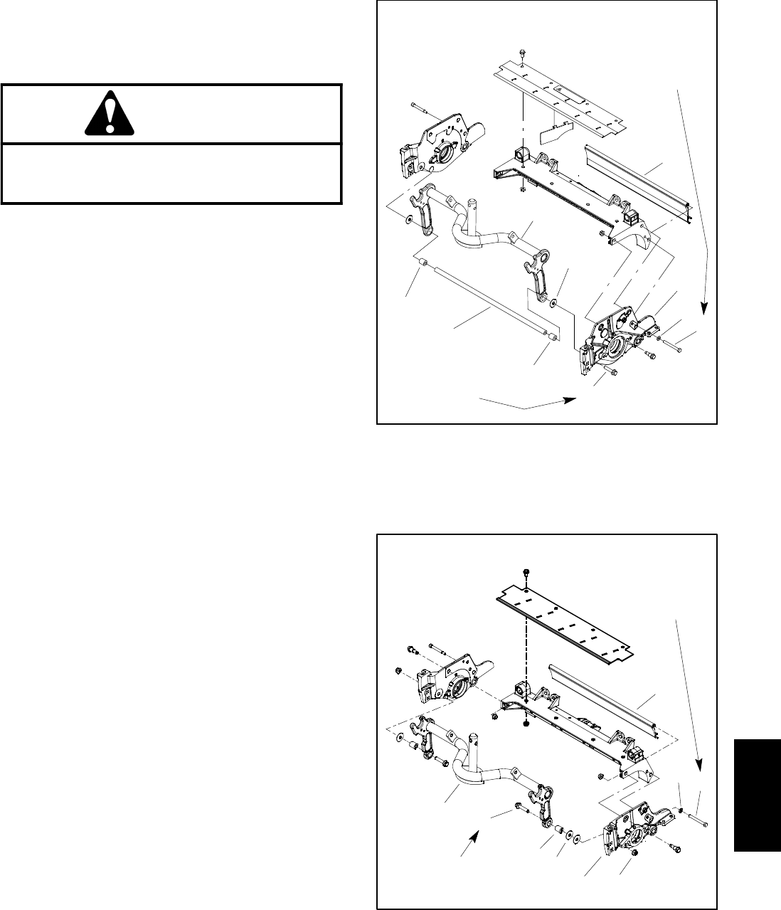
Reelmaster 5010- H Cutting Units
Page 7 - 23
4. If cutting unit is equipped with a weight on LH side
plate, remove the two (2) flange nuts securing the
weight to the side plate and remove weight from the cut-
ting unit. Remove and discard O- ring from weight.
CAUTION
Contact with the reel, bedknife or other cutting
unit parts can result in personal injury. Use
heavy gloves when removing the cutting reel.
5. If cutting unit is equipped with an optional groomer or
rear roller brush, remove components for those options
from left hand side plate of cutting unit. See Service and
Repairs section of Chapter 9 - Groomer for information
on groomer disassembly. See Rear Roller Brush and
Rear Roller Brush Drive System in the Service and Re-
pairs section of this chapter for information on rear roller
brush disassembly.
6. Remove the bedbar pivot bolt and washers from the
LH side plate. Note location of plastic and steel washers
for assembly purposes (see Bedbar Assembly in this
section).
7. Loosen fasteners that secure front and rear rollers to
LH side plate (see Front Roller and Rear Roller in this
section).
8. Remove cap screw and flat washer that secure rear
grass shield to LH side plate (Fig. 29 for 7” cutting units
or Fig. 30 for 5” cutting unit).
9. Remove fasteners that secure frame spacer, wash-
er(s) and carrier frame to LH side plate (Fig. 29 for 7” cut-
ting units or Fig. 30 for 5” cutting unit). Note the number
of washers that exist between LH side plate and carrier
frame for assembly purposes.
10.Support cutting reel to keep it from shifting or falling.
NOTE: Side plates on 5” cutting reel attach to cutting
unit frame with two (2) shoulder bolts and flange nuts.
Side plates on 7” cutting reel use three (3) shoulder bolts
and flange nuts.
11. Remove shoulder bolts (item 8) and flange nuts (item
24) that secure the LH side plate to cutting unit frame.
12.Carefully remove the LH side plate from the reel
shaft, rollers, bedbar, carrier frame and cutting unit
frame. Locate and remove flat wire spring (item 14 in
Fig. 28).
13.Carefully slide the cutting reel assembly from the RH
side plate.
14.Inspect and service cutting reel assembly (see Cut-
ting Reel Assembly Service in this section).
1. Carrier frame
2. Washer
3. Support tube
4. Frame spacer
5. Flat washer
6. Cap screw
7. Flange head screw
8. Rear grass shield
9. LH side plate
Figure 29
1
3
2
6
8
4
7
5
27 to 33 ft- lb
(37 to 44 N- m)
Loctite #242
9
4
7” CUTTING REEL
15 to 19 ft- lb
(20 to 25 N- m)
Lubricant
Antiseize
1. Carrier frame
2. Washer
3. Frame spacer
4. Flange head screw
5. Flange nut
6. LH side plate
7. Rear grass shield
8. Flat washer
9. Cap screw
Figure 30
1
32
6
8
7
5
9
4
27 to 33 ft- lb
(37 to 44 N- m)
15 to 19 ft- lb
(20to25N-m)
Lubricant
Antiseize
5” CUTTING REEL
Cutting
Units

Reelmaster 5010- H
Cutting Units Page 7 - 24
Reel Assembly Installation (Fig. 28)
1. Thoroughly clean side plates and other cutting unit
components. Inspect side plates for wear or damage
and replace if needed.
CAUTION
Contact with the reel, bedknife or other cutting
unit parts can result in personal injury. Use
heavy gloves when installing the cutting reel.
2. Position the cutting unit on a flat work area. The roll-
ers, bedbar, carrier frame and cutting unit frame should
be attached to RH side plate.
3. Apply a thin coat of antiseize lubricant to outside of
bearings on cutting reel.
4. Carefully slide the cutting reel assembly into the RH
side plate. Make sure that bearing is fully seated into
side plate.
5. Slide the LH side plate onto the cutting reel assem-
bly, front roller and rear roller. Make sure that reel end
in RH side plate does not shift in position.
6. Install shoulder bolts (item 8) and flange nuts (item
24) that secure the LH side plate to the cutting unit
frame. Torque the shoulder bolts from 27 to 33 ft-lbs (37
to 44 N- m).
7. Secure carrier frame to LH side plate:
A. For 7” cutting unit (Fig. 29), apply Loctite #242 (or
equivalent) to threads of flange head screw that se-
cures support tube, frame spacer, removed wash-
er(s) and carrier frame to LH side plate. Install screw
and torque screw from 27 to 33 ft-lbs (37 to 44
N-m).
B. For 5” cutting unit (Fig. 30), secure carrier frame,
frame spacer and removed washer(s) to LH side
plate with flange head screw and flange nut. Torque
screw from 27 to 33 ft-lbs (37 to 44 N- m).
C. After tightening flange head screw, check the
clearance between the carrier frame and side plate.
If clearance is more than 0.065” (1.7 mm), remove
flange head screw and position additional washer(s)
between carrier frame and side plate so that clear-
ance is less than 0.065” (1.7 mm). Make sure that the
carrier frame pivots freely after assembly.
8. Apply antiseize lubricant to threads of cap screw that
secures rear grass shield to LH side plate (Fig. 29 for 7”
cutting units or Fig. 30 for 5” cutting unit). Install cap
screw and flat washer to secure rear grass shield to LH
side plate. Torque screw from 15 to 19 ft-lbs (20 to 25
N-m).
9. Secure the bedbar assembly to LH side plate (see
Bedbar Assembly in this section).
10.Secure front and rear rollers to LH side plate (see
Front Roller and Rear Roller in this section).
11. Adjust cutting unit (see Cutting Unit Operator’s
Manual).
NOTE: The parallel position of the rear roller to the cut-
ting reel is controlled by the precision machined frame
and side plates of the cutting unit. If necessary, the cut-
ting unit side plates can be loosened and a slight adjust-
ment can be made to parallel the rear roller with the
cutting reel (see Leveling Rear Roller in the Set- Up and
Adjustments section of this Chapter).
12.If cutting unit is equipped with optional groomer or
rear roller brush, install components for those options to
left hand side plate of cutting unit. See Service and Re-
pairs section of Chapter 9 - Groomer for information on
groomer assembly. See Rear Roller Brush and Rear
Roller Brush Drive System in the Service and Repairs
section of this chapter for information on rear roller
brush assembly.
13.Secure weight to cutting unit side plate with two (2)
cap screws. Torque screws from 27 to 33 ft-lbs (37 to
44 N- m).
14.Lubricate cutting unit grease fitting until grease
purges from relief valve in side plate with motor. Initial
greasing may require several pumps of a hand grease
gun.
15.Install cutting unit to the machine.
16.Plug the 48 VDC battery disconnect back in before
operating the machine.

Reelmaster 5010- H Cutting Units
Page 7 - 25
This page is intentionally blank.
Cutting
Units
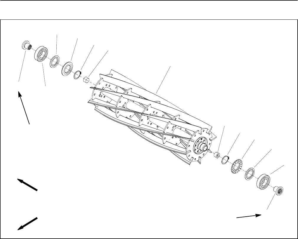
Reelmaster 5010- H
Cutting Units Page 7 - 26
Cutting Reel Assembly Service
1. Cutting reel
2. Threaded insert (RH thread)
3. Bearing
4. Flocked seal
5. Special washer
6. Retaining ring
7. Reel shaft plug
8. Threaded insert (LH thread)
Figure 31
85 to 95 ft- lb
(115 to 128 N- m)
85 to 95 ft- lb
(115 to 128 N- m)
Loctite #242
Loctite #242
3
2
6
5
4
1
FRONT
RIGHT
(Right Hand Threads)
(Left Hand Threads)
7
8
3
4
7
6
5
Disassembly of Cutting Reel (Fig. 31)
1. Remove threaded inserts (items 2 and 8) from cut-
ting reel. The threaded insert with the groove on the face
has LH threads and is in end of reel shaft identified with
a groove that is just inside of reel spider (Fig. 32). Use
correct spline insert tool for insert removal (see Special
Tools in this chapter).
2. Slide bearings (item 3) from reel shaft.
3. Note orientation of flocked seals (item 4) for assem-
bly purposes (flocked (red) side orientated toward bear-
ing location). Remove flocked seals from reel shaft.
4. Note orientation of special washers (item 5) for as-
sembly purposes (flat side toward bearing location).
Carefully drive special washers from reel shaft.
5. If necessary, remove reel shaft plugs (item 7) from
reel shaft.
6. Discard removed components and replace during
cutting reel assembly.
Inspection of Cutting Reel (Fig. 31)
1. Check the threaded inserts for excessive wear or
distortion. Replace inserts if damage is evident.
2. Inspect the reel shaft as follows. If reel damage is de-
tected, replace reel.
A. Check the reel shaft for bending and distortion by
placing the shaft ends in V- blocks.
B. Check the reel blades for bending or cracking.
C. Check the service limit of the reel diameter (see
Preparing a Reel for Grinding in this section).
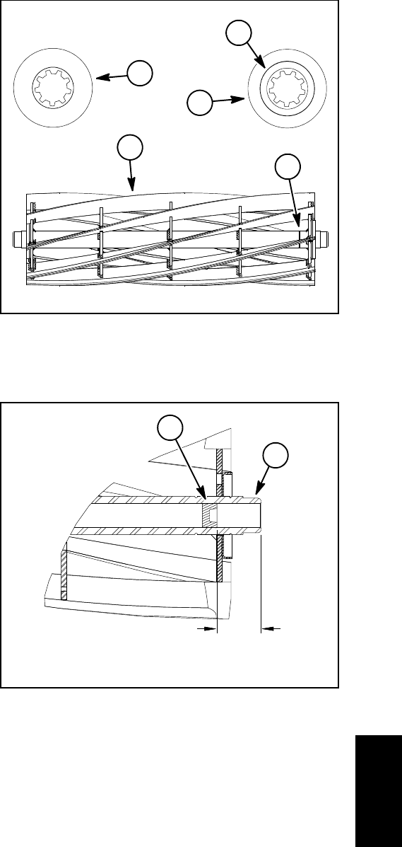
Reelmaster 5010- H Cutting Units
Page 7 - 27
Assembly of Cutting Reel (Fig. 31)
1. If removed, install new reel shaft plugs into cutting
reel shaft. Plugs should be recessed into reel shaft from
1.370” to 1.630” (34.8 to 41.4 mm) (Fig. 33).
2. Install two (2) new retaining rings onto cutting reel
shaft. Make sure that the retaining rings are fully seated
into the grooves on the shaft.
3. Carefully drive special washers onto reel shaft with
beveled side of washers toward reel (flat side toward
bearing location). Installed washers should be tight
against retaining ring and should not wobble as the reel
is rotated.
IMPORTANT: The flocked seal should be installed
so the flocked (red) side of the seal is toward the
bearing location.
4. Slide flocked seals (flocked (red) side orientated to-
ward bearing location) and bearings fully onto reel shaft.
Flocked seals and bearings should bottom on reel shaft
shoulder.
NOTE: The threaded insert with the groove on the face
has LH threads and should be installed in end of reel
shaft identified with a groove that is just inside of reel spi-
der (Fig. 32).
5. Clean threads of threaded inserts and cutting reel
shaft. Apply Loctite #242 (or equivalent) to threads of in-
serts, thread inserts into reel shaft and torque from 85
to 95 ft-lb (115 to 128 N- m). Use correct spline insert
tool for insert installation (see Special Tools in this chap-
ter).
6. Fill threaded insert splines with high temp Mobil
XHP- 222 grease or equivalent.
1. Cutting reel
2. Reel shaft groove
3. Insert with LH threads
4. Groove on face
5. Insert with RH threads
Figure 32
2
1
5
3
4
1. Cutting reel shaft 2. Reel shaft plug
Figure 33
1.370” to 1.630”
(34.8 to 41.4 mm)
2
1
Cutting
Units
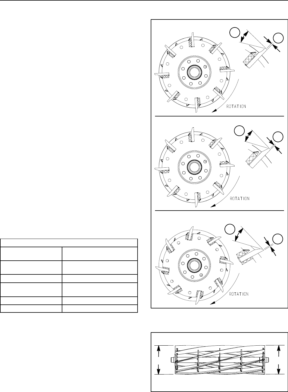
Reelmaster 5010- H
Cutting Units Page 7 - 28
Preparing Reel for Grinding
Three (3) types of cutting reel designs are used in cutting
units for Reelmaster 5010- H machines: scalloped radi-
al reel, tapered radial reel and tapered forward swept
reel. The different types of individual reel blades are
shown in Figure 34. The radial reel designs have blades
that are placed in line with the center of the reel shaft.
The rear of the blades either have a scalloped relief or
a tapered relief. The forward swept reel have blades that
have a slight forward slant. The rear of the forward swept
reel blades have a tapered relief.
Before grinding a reel, make sure to identify the type of
reel design to make sure that grinding is correctly done.
NOTE: Before grinding a cutting reel, make sure that all
cutting unit components are in good condition. Depend-
ing on type of grinder used, faulty cutting unit compo-
nents can affect grinding results.
NOTE: When grinding, be careful to not overheat the
cutting reel blades. Remove small amounts of material
with each pass of the grinder.
Follow reel grinder manufacturer’s instructions to grind
cutting reel to Toro specifications (see Reel Grinding
Specifications chart below). Additional reel grinding in-
formation can be found in your Cutting Unit Operator’s
Manual and the Toro General Service Training Book,
Reel Mower Basics (part no. 09168SL).
After completing the reel grinding process, adjust cut-
ting unit (see Cutting Unit Operator’s Manual).
Reel Grinding Specifications
Reel Diameter (New) 5.060in(128.5mm)for5”reel
7.060in(179.3mm)for7”reel
Service Limit -
Reel Diameter
4.500 in (114 mm) for 5”reel
6.600 in (168 mm) for 7” reel
Reel Shaft Diameter (OD) 1.313in(33.3mm)
Service Limit -
Reel Diameter Taper
0.010 in (0.25 mm) for both
5” and 7” reel (Fig. 35)
BladeLandWidth 0.050 to 0.060 in (1.3 to 1.5 mm)
Blade Relief Angle 30o+/- 5o
NOTE: Relief grind of cutting reel blades is necessary
when blade land width exceeds 0.120” (3 mm).
NOTE: After grinding the reel and/or bedknife, check
the reel to bedknife contact again after cutting two (2)
fairways. During this initial use, any burrs will be re-
moved from reel and bedknife which may create improp-
er reel to bedknife clearance and thus accelerate wear.
This practice of re- checking the reel to bedknife contact
after grinding will extend the longevity of the sharpness
of the edge of the reel and the bedknife.
Figure 34
SCALLOPED RADIAL REEL
2
1
2
1
TAPERED RADIAL REEL
2
1
TAPERED FORWARD SWEPT REEL
1. Blade land width 2. Blade relief angle
Figure 35
D2
D1
Reel Diameter Taper = D1 - D2

Reelmaster 5010- H Cutting Units
Page 7 - 29
This page is intentionally blank.
Cutting
Units
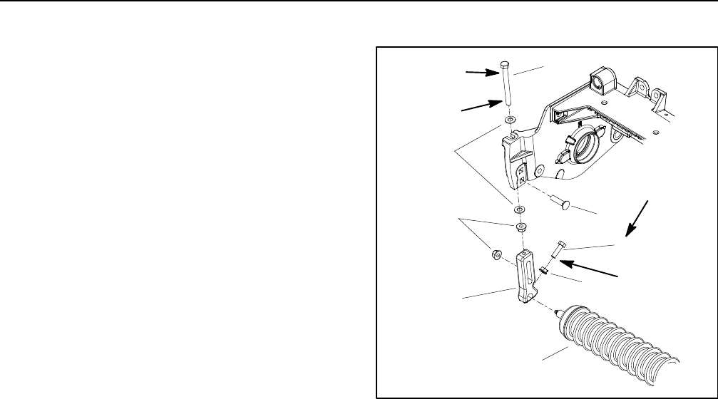
Reelmaster 5010- H
Cutting Units Page 7 - 30
Front Roller
Removal (Fig. 36)
1. Position machine on a clean and level surface, lower
cutting units, stop engine, engage parking brake and re-
move key from the ignition switch.
2. Remove the cutting unit from the machine and place
on a level working surface. Use cutting unit kickstand
(see Special Tools in this chapter) to raise front roller
from work surface.
3. Loosen flange nut and cap screw securing the front
roller shaft to each front height- of- cut (roller) bracket.
4. On one of the height- of- cut (roller) brackets:
A. Remove flange lock nut and carriage screw that
secure bracket to the cuttingunitsideplate.
B. Remove the height- of- cut (roller) bracket from
the cutting unit.
5. Slide the front roller assembly from the remaining
height- of- cut (roller) bracket on the cutting unit.
6. If necessary, remove the second height- of- cut (roll-
er) bracket from the cutting unit.
Installation (Fig. 36)
1. Place cutting unit on a level working surface and use
cutting unit kickstand (see Special Tools in this chapter)
to support cutting unit.
2. Inspect condition of cap screws (item 1) in both
height- of- cut (roller) brackets. Replace cap screw(s) if
necessary:
A. Place two (2) flat washers on cap screw and
thread flange lock nut onto cap screw to a position
0.750” (19 mm) from screw head.
B. Apply antiseize lubricant to cap screw threads
that will extend into height- of- cut (roller) bracket.
C. Thread cap screw into bracket.
NOTE: When assembling height- of- cut (roller) brack-
ets to side plate, make sure that cap screw head and one
washer are above adjustment flange on side plate and
second washer and flange lock nut are below flange.
3. If both front height- of- cut (roller) brackets were re-
moved from cutting unit side plate, position one of the
brackets to side plate. Secure bracket to side plate with
carriage screw and flange lock nut.
1. Cap screw
2. Flat washer
3. Flange lock nut
4. HOC (roller) bracket
5. Carriage screw
6. Cap screw
7. Flange nut
8. Front roller assembly
Figure 36
1
2
3
4
5
6
7
8
15 to 19 ft- lb
(20 to 26 N- m)
Antiseize
Lubricant
Loctite #242
Loctite #242
4. Slide front roller shaft into bracket attached to the
cutting unit. Slide second height- of- cut (roller) bracket
onto the other end of roller shaft. Secure second bracket
to cutting unit side plate with carriage screw and flange
nut.
5. Apply Loctite #242 (or equivalent) to exposed
threads of cap screw (item 1) between flange of side
plate and position of flange lock nut (item 3) on cap
screw. Tighten flange lock nut on cap screw and then
loosen nut 1/4 to 1/2 turn. Cap screw should rotate freely
with little (if any) endplay after lock nut installation.
6. Apply Loctite #242 (or equivalent) to threads of two
(2) cap screws (item 6). Center front roller to the cutting
reel and secure in place with two (2) cap screws. Torque
cap screws from 15 to 19 ft- lb (20 to 26 N- m).Secure
cap screws with flange nuts.
7. Lubricate front roller grease fittings.
8. Adjust cutting unit (see Cutting Unit Operator’s
Manual).
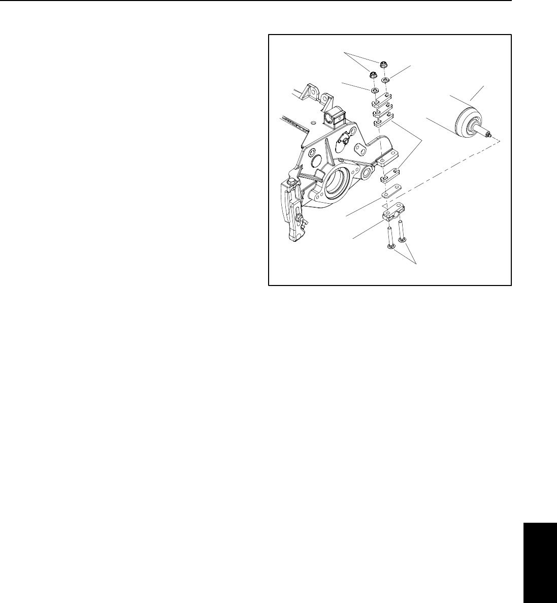
Reelmaster 5010- H Cutting Units
Page 7 - 31
Rear Roller
Removal (Fig. 37)
1. Position machine on a clean and level surface, lower
cutting units, stop engine, engage parking brake and re-
move key from the ignition switch.
2. Remove the cutting unit from the machine and place
onalevelworkingsurface.Place support blocks under
bedbar to raise rear roller from work surface.
3. Loosen two (2) flange nuts that secure the rear roller
shaft to each rear roller bracket.
4. On one of the rear roller brackets:
NOTE: On cutting units equipped with optional High
Height of Cut Kit, there will be additional roller shims
installed between rear roller bracket and cutting unit
side plate.
A. Remove flange nuts, washers and carriage
screws that secure rear roller bracket and roller
shims to the cutting unit side plate.
B. Remove the roller bracket and roller shims from
the rear roller and cutting unit.
5. Slide the rear roller assembly from the remaining
rear roller bracket on the cutting unit.
6. If necessary, remove the second rear roller bracket
and roller shims from the cutting unit.
Installation (Fig. 37)
1. Place cutting unit on a level working surface.
NOTE: Refer to Cutting Unit Operator’s Manual for
number of roller shims required for various height of cut
settings.
NOTE: A 0.010” shim (part number 107- 4001) is avail-
able to allow for leveling of the rear roller (see Leveling
Rear Roller in the Set- up and Adjustments section of
this chapter). If necessary, this shim would be used on
one side of the rear roller and should be installed be-
tween the rear roller bracket and roller shim.
2. If both rear roller brackets were removed from cutting
unit side plate, position brackets and roller shims to one
of the side plates. Install two (2) carriage screws and
flange nuts to retain bracket in position. Do not fully tight-
en flange nuts.
1. Rear roller assembly
2. Rear roller bracket
3. Carriage screw
4. Flange nut
5. Washer
6. Roller shim
7. 0.010” shim (if needed)
Figure 37
1
2
3
4
5
6
5
7
3. Slide rear roller shaft into the rear roller bracket at-
tached to the cutting unit. Slide second rear roller brack-
et onto the other end of roller shaft. Secure second roller
bracket and shims to cutting unit side plate with two (2)
carriage screws, washers and flange nuts. Do not fully
tighten flange nuts.
4. Center rear roller to the cutting reel and secure in
place by tightening four (4) flange nuts.
5. Lubricate rear roller grease fittings.
6. Adjust cutting unit (see Cutting Unit Operator’s
Manual).
Cutting
Units
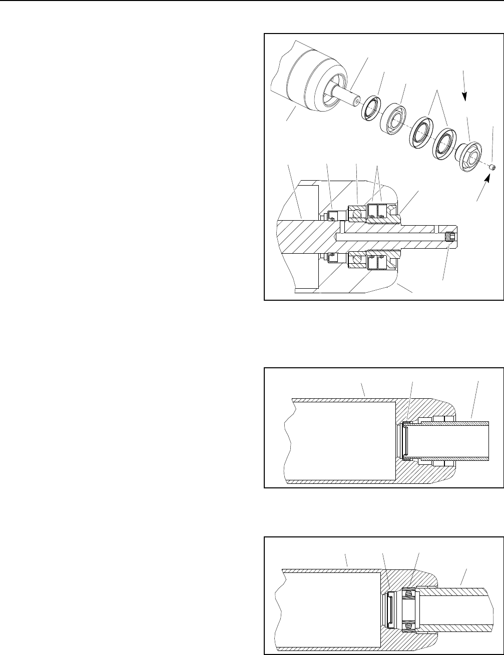
Reelmaster 5010- H
Cutting Units Page 7 - 32
Roller Service
Disassembly (Fig. 38)
1. Remove bearing lock nut from each end of roller
shaft.
2. Loosely secure roller assembly in bench vise and
lightly tap one end of roller shaft until outer seals and
bearing are removed from opposite end of roller tube.
Remove second set of outer seals and bearing from roll-
er tube by tapping on opposite end of shaft. Remove
shaft from roller tube.
3. Carefully remove inner seal from both ends of roller
tube taking care to not damage tube surfaces.
4. Discard removed seals and bearings.
5. Clean roller shaft and all surfaces on the inside of the
roller tube. Inspect components for wear or damage.
Also, carefully inspect seating surface and threads of
bearing lock nuts. Replace all damaged components.
Assembly (Fig. 38)
1. Install inner seals into roller tube making sure that
seal lip (and garter spring) faces end of tube. Use inner
seal tool (see Special Tools in this chapter) and soft face
hammer to fully seat seals against roller shoulder (Fig.
39). Apply a small amount of grease around the lip of
both inner seals after installation.
IMPORTANT: During assembly process, frequently
check that bearings rotate freely and do not bind. If
any binding is detected, consider component re-
moval and reinstallation.
2. Install new bearing and outer seals into one end of
roller tube:
A. Position a new bearing into one end of roller tube.
Use bearing/outer seal tool (see Special Tools in this
chapter) with a soft face hammer to fully seat bearing
against roller shoulder (Fig. 40). After bearing instal-
lation, make sure that it rotates freely with no binding.
B. Apply a small amount of grease around the lip of
both outer seals.
C. Install first outer seal into roller tube making sure
that seal lip (and garter spring) faces end of tube.
Use bearing/outer seal tool (see Special Tools in this
chapter) and soft face hammer to lightly seat seal
against roller shoulder (Fig. 41). Make sure that
bearing still freely rotates after seal installation.
D. Using the same process, install second outer
seal making sure to not crush the installed outer seal.
Again, make sure that bearing still freely rotates.
1. Roller tube
2. Roller shaft
3. Inner seal
4. Bearing
5. Outer seal
6. Bearing lock nut
7. Set screw
Figure 38
6
3
5
4
2
17
6
35
4
2
17
50 to 60 ft- lb
(68to81N-m)
Loctite #242
1. Roller tube
2. Inner seal
3. Inner seal tool
Figure 39
321
1. Roller tube
2. Inner seal
3. Bearing
4. Bearing/outer seal tool
Figure 40
321
4
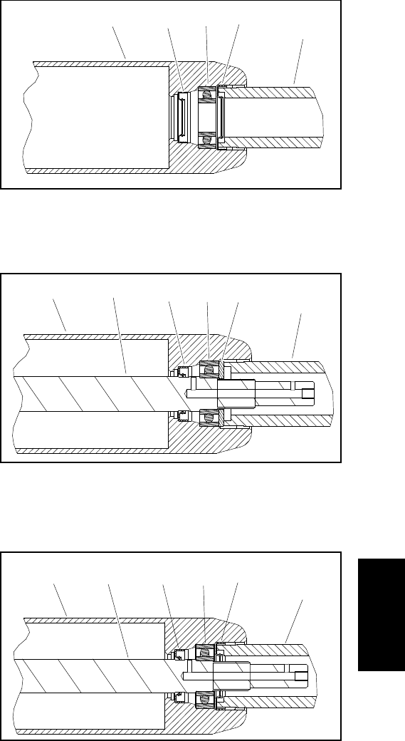
Reelmaster 5010- H Cutting Units
Page 7 - 33
3. From the roller tube end with only the inner seal
installed, carefully install the roller shaft into the roller
tube. Make sure that seals are not damaged as shaft is
installed.
4. Install new bearing and outer seals into second end
of roller tube:
A. Position a second new bearing to roller shaft and
tube. Position washer (see Special Tools in this
chapter) on bearing to allow pressing on both inner
and outer bearing races simultaneously.
B. Use washer and bearing/outer seal tool (see
Special Tools in this chapter)withasoftfacehammer
to fully seat bearing (Fig. 42). After bearing installa-
tion, make sure that shaft freely rotates and that no
binding is detected. If necessary, lightly tap bearing
and/or shaft ends to align shaft and bearings. Re-
move washer from roller.
C. Apply a small amount of grease around the lip of
both outer seals.
D. Carefully install first outersealintorollertube
making sure that seal lip (and garter spring) faces
end of tube. Use bearing/outer seal tool (see Special
Tools in this chapter) and soft face hammer to lightly
seat seal (Fig. 43). Make sure that shaft and bear-
ings still freely rotate after seal installation.
E. Using the same process, install second outer
seal making sure to not crush the installed outer seal.
Again, make sure that shaft and bearings still freely
rotate.
IMPORTANT: Make sure that all grease is removed
from shaft threads to prevent bearing lock nut loos-
ening.
5. Thoroughly clean threads on both ends of roller
shaft.
NOTE: If original bearing lock nut(s) are being used,
apply Loctite #242 (or equivalent) to threads of lock
nut(s).
6. Install bearing lock nut onto each end of the roller
shaft. Make sure that outer seals are not damaged dur-
ing nut installation. Torque lock nuts from 50 to 60 ft- lb
(68to81N-m).
7. If set screw was removed from either end of roller
shaft, apply Loctite #242 (or equivalent) to threads of re-
moved set screw and install into roller shaft. Tighten set
screw until it bottoms in shaft and is recessed in shaft.
IMPORTANT: When roller assembly is installed to
cutting deck, make sure that grease groove in each
roller mount aligns with the grease hole in each end
of roller shaft.
NOTE: After roller is installed to cutting deck, lubricate
roller grease fittings, rotate roller to properly distribute
grease in bearings and clean excess grease from roller
ends. A properly assembled roller should rotate with
less than 5 in- lbs (0.68 N- m) resistance.
1. Roller tube
2. Inner seal
3. Bearing
4. Outer seal
5. Bearing/outer seal tool
Figure 41
34
2
1
5
1. Roller tube
2. Roller shaft
3. Inner seal
4. Bearing
5. Washer
6. Bearing/outer seal tool
Figure 42
34
2
156
1. Roller tube
2. Roller shaft
3. Inner seal
4. Bearing
5. Outer seal
6. Bearing/outer seal tool
Figure 43
34
2
15
6
Cutting
Units
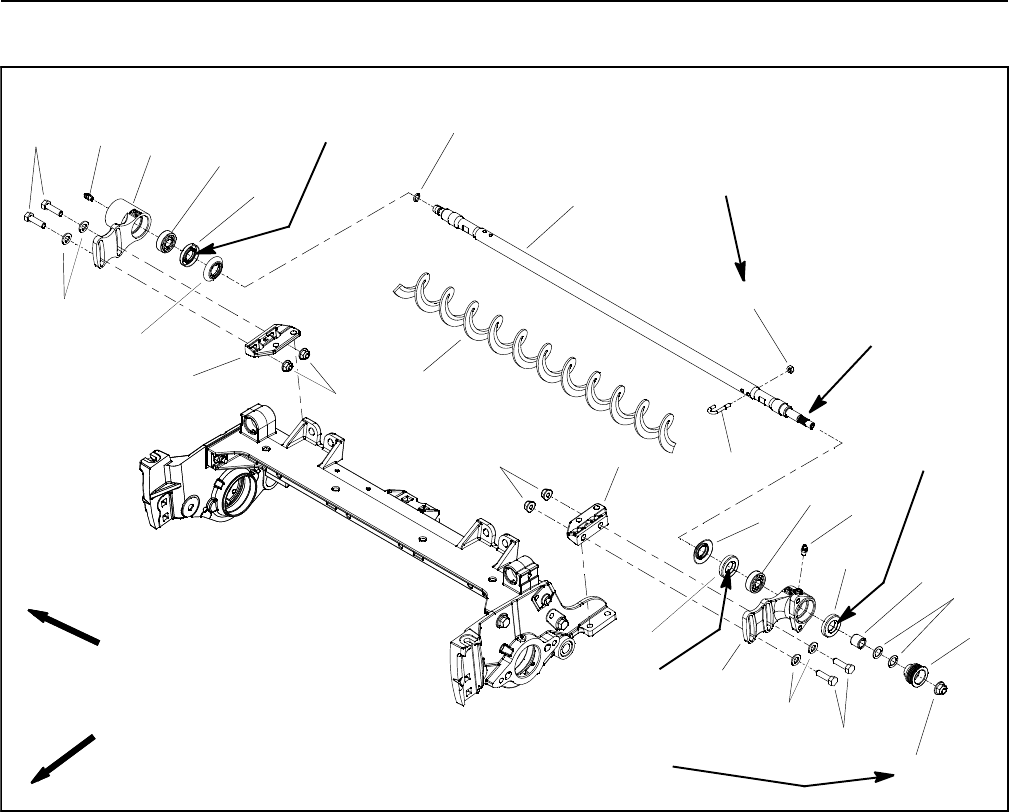
Reelmaster 5010- H
Cutting Units Page 7 - 34
Rear Roller Brush (Optional)
1. Brush bearing housing (non- drive)
2. Brush bearing housing (drive)
3. O- ring
4. Roller brush shaft
5. Flange nut (4 used)
6. Mounting bracket (2 used)
7. Excluder seal (2 used)
8. Flat washer (4 used)
9. Cap screw (4 used)
10. Spacer
11. Flat washer (for pulley alignment)
12. Driven pulley
13. Flange nut
14. Roller brush
15. Lock nut
16. J- bolt (2 used)
17. Grease fitting
18. Grease seal
19. Ball bearing
20. Grease fitting
21. Grease seal
22. Ball bearing
Figure 44
v
Antiseize
Lubricant
FRONT
RIGHT
FRONT
RIGHT
20 to 25 in- lb
(2.3 to 2.8 N- m)
27 to 33 ft- lb
(37to44N-m)
Grease
Seal Lip 2
3
6
8
9
10 11
13
1
5
7
12
14
18
16
17
18
19
20
4
21
22
5
8
9
7
6
15
Grease
Seal Lip
Grease
Seal Lip
NOTE: Drive components for the rear roller brush are
located on the opposite side of the cutting unit from the
cutting reel motor. Figure 44 shows components used
when the brush drive is on the left side of the cutting unit.
NOTE: The Installation Instructions for the rear roller
brush kit has detailed information regarding assembly
and adjustment. Use those Instructions along with this
Service Manual when servicing the rear roller brush.
Disassembly (Fig. 44)
1. Position machine on a clean and level surface, lower
cutting units, stop engine, engage parking brake and re-
move key from the ignition switch.
2. To prevent unexpected reel motor operation, discon-
nect motors from the electrical power supply by unplug-
ging the 48 VDC battery disconnect (see 48 VDC
Battery Disconnect in the General Information section of
this chapter).
3. To remove roller brush from brush shaft:
A. Remove the non- drive brush bearing housing
(item 1) from cutting unit.
B. Slide excluder seal from roller brush shaft.
C. Remove lock nut and J- bolt from both ends of the
brush.
D. While rotating brush, slide brush from the shaft.
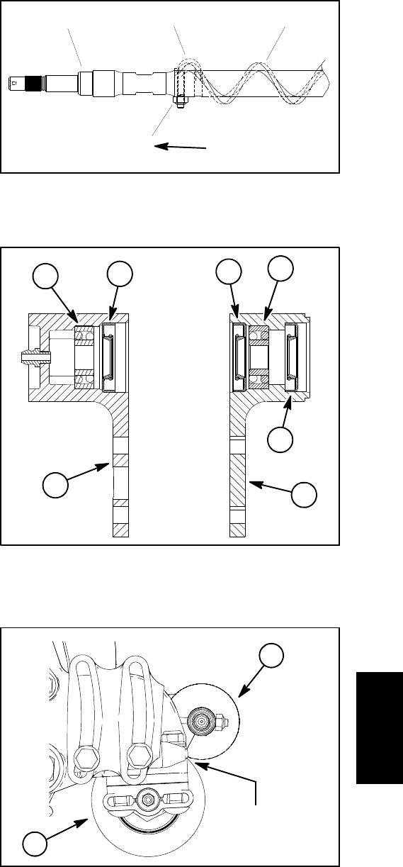
Reelmaster 5010- H Cutting Units
Page 7 - 35
4. Disassemble roller brush components as necessary
using Figures 44 as a guide. If drive brush bearing hous-
ing (item 2) or driven pulley (item 12) need to be re-
moved, brush cover and drive belt removal will be
necessary (see Rear Roller Brush Drive System in this
section).
Assembly (Fig. 44)
1. If seals or bearings were removed from brush bear-
ing housings, install new components noting proper ori-
entation as shown in Figure 46.
A. Pack bearings with high temp Mobil XHP- 222
grease (or equivalent) before installation.
B. Press bearing into bearing housing so that bear-
ing contacts shoulder in housing bore.
C. Install grease seals so that seal lips are posi-
tioned toward the brush location as shown in Fig. 46.
Press seals into housing so that seal contacts bore
shoulder.
2. If roller brush was removed from roller shaft, slide
brush onto shaft while rotating brush. Secure brush to
shaft with two (2) J- bolts and lock nuts. Make sure that
theJ-boltsareinstalledwiththethreadedportiononthe
outside of the brush (Fig. 45). Torque lock nuts from 20
to 25 in- lb (2.3 to 2.8 N- m).
3. Assemble roller brush components using Figure 44
as a guide noting the following items:
A. Apply coating of grease to lips of grease seals in
brush bearing housing before inserting brush shaft
into housing.
B. If driven pulley (item 12) was removed from roller
brush shaft, apply antiseize lubricant to splines of
pulley bore and slide pulley onto shaft. Install and
tighten flange nut until pulley is seated onto shaft and
then torque flange nut from 27 to 33 ft- lb (37 to 44
N-m).Usea½wrench on roller brush shaft flats to
prevent shaft from rotating when tightening nut.
C. Position excluder seals on brush shaft so that
seals just touch bearing housings.
D. If driven pulley (item 12) was removed, check and
adjust alignment of drive and driven pulleys (see
Rear Roller Brush Drive System in this section).
4. Check that brush is parallel to rear roller with 0.060”
(1.5 mm) clearance to light contact with rear roller (Fig.
47). If contact is incorrect, brush operation will be ad-
versely affected.
5. Lubricate grease fittings on brush housings until
grease purges past inboard seals. Wipe excess grease
from seals and fittings.
6. Once all rear roller brush service is completed, plug
the 48 VDC battery disconnect back in before operating
the machine.
1. Roller brush shaft
2. J- bolt
3. Roller brush
4. Lock nut
Figure 45
123
420 to 25 in- lb
(2.3 to 2.8 N- m)
1. Bearing
2. Inner grease seal
3. Outer grease seal
4. Housing (non- driven)
5. Housing (driven)
Figure 46
1
4
2
3
1
5
2
1. Rear roller brush 2. Rear roller
Figure 47
2
1
0.060” (1.5 mm)
Clearance to
Light Contact
Cutting
Units
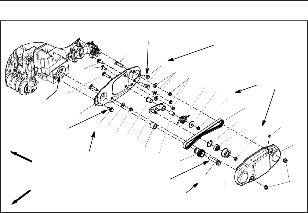
Reelmaster 5010- H
Cutting Units Page 7 - 36
Rear Roller Brush Drive System (Optional)
1. Carriage screw (2 used)
2. Carriage screw (3 used)
3. Brush plate
4. Cap screw (2 used)
5. Flat washer (4 used)
6. Lock nut (6 used)
7. Idler arm
8. Idler spacer
9. Idler spring
10. Pivot washer
11. Drive belt
12. Idler pulley
13. Retaining ring
14. Bearing
15. Shoulder screw
16. Flange head screw
17. Drive pulley
18. Spacer
19. Flange bushing
20. Cover
21. Flange nut (2 used)
22. Set screw (top of cover only)
Figure 48
v
FRONT
RIGHT
10 to 15 ft- lb
(14to20N-m)
35 to 40 ft- lb
(48to54N-m)
2
3
6
8
910
11
13
15
7
12
14
15
16
17
18
19 20
4
6
6
2
5
6
21
15 to 19 ft- lb
(20to25N-m)
Loctite #242
22
Loctite #242
15 to 19 ft- lb
(20to25N-m)
Loctite #242
Grease
Grommet ID
NOTE: Drive components for the rear roller brush are
located on the opposite side of the cutting unit from the
cutting reel motor. Figure 44 shows components used
when the brush drive is on the left side of the cutting unit.
NOTE: The Installation Instructions for the rear roller
brush kit has detailed information regarding assembly
and adjustment. Use those Instructions along with this
Service Manual when servicing the rear roller brush.
Disassembly (Fig. 48)
1. Position machine on a clean and level surface, lower
cutting units, stop engine, engage parking brake and re-
move key from the ignition switch.
2. To prevent unexpected reel motor operation, discon-
nect motors from the electrical power supply by unplug-
ging the 48 VDC battery disconnect (see 48 VDC
Battery Disconnect in the General Information section of
this chapter).
3. Remove cover (item 20) to access rear roller brush
drive components.
4. Remove roller brush drive components as neces-
saryusingFigure48asaguide.
5. Remove roller brush drive shaft if needed (Fig. 49):
A. Remove socket head screws that secure drive
housing to cutting unit side plate and remove hous-
ing from cutting unit.
IMPORTANT: If rear roller brush drive is on left
side of cutting unit, drive shaft has left hand
threads and can be identified by a groove on the
flange. If the rear roller brush drive is on right
side of cutting unit, drive shaft has right hand
threads and does not have a groove on the flange
(Fig. 50).
B. Loosen and remove drive shaft from cutting reel.
Reelmaster 5010- H Cutting Units
Page 7 - 37
Assembly (Fig. 48)
1. Install drive shaft if it was removed (Fig. 49):
IMPORTANT: If rear roller brush drive is on left
side of cutting unit, drive shaft has left hand
threads and can be identified by a groove on the
flange. If the rear roller brush drive is on right
side of cutting unit, drive shaft has right hand
threads and does not have a groove on the flange
(Fig. 50).
A. Apply Loctite #242 (or equivalent) to threads of
drive shaft. Thread drive shaft into cutting reel and
torque from 85 to 95 ft- lb (115 to 128 N- m).
B. Make sure that O- ring is placed on inner flange of
drive housing.
C. Position housing to cutting unit side plate and se-
cure to cutting unit with two (2) socket head screws.
D. Make sure that grommet groove is correctly seat-
ed on flange in drive housing bore.
2. Assemble roller brush components using Figure 48
as a guide.
A. During assembly, apply Loctite #242 (or equiva-
lent) to threads of fasteners and torque fasteners as
shown in Figure 48.
B. Apply a light coating of grease to inner diameter
of the grommet in drive bearing housing before in-
stalling brush plate.
C. Brushplateshouldbeinstalledsothatidlerpulley
assembly is toward the bottom of the plate. Also, the
shoulder bolt (item 15) should not clamp the brush
plate to the drive housing during assembly.
D. When installing drive pulley (item 17), make sure
that tabs on pulley engage slot in drive shaft.
E. Idler arm (item 7) should be free to rotate after as-
sembly to brush plate. Make sure that idler spring is
installed so that it can rotate the idler arm and pulley
and apply tension to the drive belt.
F. After drive belt installation, make sure that the
ribs on the belt are properly seated in the grooves of
both the drive and driven pulleys and that the belt is in
the center of the idler pulley.
1. Drive housing
2. Drive shaft
3. O- ring
4. Socket head screw
5. Grommet
Figure 49
1
2
3
4
5
4
NOTE: 5” CUTTING UNIT SHOWN
85 to 95 ft- lb
(115 to 128 N- m)
Loctite #242
Figure 50
Drive Shaft
With RH Threads
(No Groove)
Drive Shaft
With LH Threads
(With Groove)
1. Driven pulley
2. Drive pulley
3. Straight edge
Figure 51
2
1
3
Cutting
Units
Reelmaster 5010- H
Cutting Units Page 7 - 38
3. After assembly (including drive belt installation),
check alignment of pulleys with a straight edge placed
along the outer face of the drive pulley (Fig. 51).
A. The outer faces of the drive and driven pulleys
(not the idler pulley) should be in- line within 0.030”
(0.76 mm).
B. If necessary to align pulleys, remove driven
pulley from brush shaft and add or remove flat wash-
er(s) until drive and driven pulleys are correctly
aligned (Fig. 52).
C. If driven pulley was removed from roller brush
shaft, apply antiseize lubricant to splines of pulley
bore and slide pulley onto shaft. Install and tighten
flange nut until pulley is seated onto shaft and then
torque flange nut from 27 to 33 ft- lb (37 to 44 N- m).
Use a ½wrench on roller brush shaft flats to prevent
shaft from rotating when tightening nut.
4. Check that brush is parallel to rear roller with 0.060”
(1.5 mm) clearance to light contact with rear roller. If con-
tact is incorrect, brush operation will be adversely affect-
ed.
5. Install cover (item 20).There should not be a set
screw installed in the bottom of the cover.
6. Lubricate grease fittings on brush housings until
grease purges past inboard seals. Wipe excess grease
from seals and fittings.
7. Once all rear roller brush service is completed, plug
the 48 VDC battery disconnect back in before operating
the machine.
1. Flange nut
2. Driven pulley
3. Flat washer
4. Roller brush shaft
Figure 52
1
2
3
4
Antiseize
Lubricant
27 to 33 ft- lb
(37 to 44 N- m)

Reelmaster 5010- H GroomerPage 8 - 1
Chapter 8
Groomer
Table of Contents
GENERAL INFORMATION 2.....................
Groomer Kit Installation Instructions 2...........
48 VDC Battery Disconnect 2..................
SPECIAL TOOLS 3.............................
GROOMING PERFORMANCE 4..................
TROUBLESHOOTING 5.........................
Groomer Reel Mechanical Problems 5...........
ADJUSTMENTS 7..............................
Groomer Height/Depth Adjustment 7............
SERVICE AND REPAIRS 8......................
Groomer Drive Assembly 8....................
Groomer Reel and Groomer Plate Assembly 10...
Groomer Reel Service 14......................
Height Adjuster Assembly 16...................
Groomer
Reelmaster 5010- HGroomer Page 8 - 2
General Information
Groomer Kit Installation Instructions
The groomer kit installation instructions provides infor-
mation regarding the installation, set- up and operation
of the optional groomer on your Reelmaster machine.
Refer to this publication for additional information when
servicing the groomer.
48 VDC Battery Disconnect
CAUTION
Before installing, removing or servicing compo-
nents in the 48 VDC system (e.g. cutting unit mo-
tors, motor/generator), separate the 48 VDC bat-
tery disconnect. This will prevent unexpected
operation of 48 VDC system components.
The 48 VDC battery disconnect is attached to the right
frame rail under the operator seat (Fig. 1). Unplug the
disconnect to make sure that 48 VDC components do
not operate unexpectedly. Apply dielectric grease to the
contact surfaces of the battery disconnect and plug the
battery disconnect back in after service to the 48 VDC
system is completed.
1. RH frame rail 2. 48V battery disconnect
Figure 1
2
1
FRONT
Reelmaster 5010- H GroomerPage 8 - 3
Special Tools
Order Special Tools from your Toro Distributor. Some
tools may have been supplied with your machine or are
available as Toro parts.
Spline Insert Tool
Toro Part Number: TOR4112 (8 tooth for 5 inch reels)
TOR4074 (9 tooth for 7 inch reels)
Use spline insert tool for rotating cutting reel when motor
is removed. Also use this tool for installation of threaded
inserts into cutting reel shaft.
Figure 2
Pulley Alignment Tool
Toro Part Number: 114- 5446
Use pulley alignment tool to verify alignment of groomer
drive and driven pulleys.
Figure 3
Gauge Bar Assembly
Toro Part Number: 108- 6715
Use gauge bar to verify height- of- cut adjustment. Also
used for adjustment of optional groomer.
Figure 4
Used for Height- of-
Cut adjustment
groomer
adjustment
Used for
Groomer
Reelmaster 5010- HGroomer Page 8 - 4
Grooming Performance
There are a number of factors that can affect the perfor-
mance of grooming. These factors vary for different golf
courses and from fairway to fairway. It is important to in-
spect the turf frequently and vary the grooming practice
with turf needs.
IMPORTANT: Improper or overaggressive use of
the groomer (e.g. too deep or too frequent groom-
ing) may cause unnecessary stress on the turf lead-
ing to severe turf damage. Use the groomer
carefully. READ AND UNDERSTAND THE GROOM-
ER OPERATION INSTRUCTIONS BEFORE OPERAT-
ING OR TESTING GROOMER PERFORMANCE.
It is important to remember that factors affecting quality
of cut also affect grooming performance.
Variables That Affect the Use and Performance of
Groomers:
1. The growing season and weather conditions.
2. General turf conditions.
3. The frequency of grooming/cutting - number of cut-
tings per week and how many passes per cutting.
4. The height- of- cut.
5. Thegroomingdepth.
6. Thetypeofgrass.
7. The amount of time that a groomer reel has been in
use on a particular turf area.
8. The amount of traffic on the turf.
9. The overall turf management program - irrigation,
fertilizing, weed control, coring, overseeding, sand
dressing, disease control and pest control.
10.Stress periods for turf - high temperatures, high hu-
midity, unusually high traffic.

Reelmaster 5010- H GroomerPage 8 - 5
Troubleshooting
Groomer Reel Mechanical Problems
Problem Possible Causes Correction
No rotation of the groomer reel. The groomer drive belt needs to be
adjusted.
Failed groomer idler bearing(s) in
groomer side plate(s).
Broken or damaged idler spring.
The groomer drive belt is worn, bro-
ken or damaged.
Grooming depth is too deep.
Groomer drive shaft is loose in cut-
ting reel.
Groomer drive pulley square key is
damaged or missing.
Flange head screw that secures
groomer drive pulley is loose or
damaged.
Adjust groomer drive belt.
Replace faulty bearing(s).
Replace spring.
If the drive belt slips, it probably is
out of adjustment or worn.
Repair or replace drive belt if nec-
essary. A broken or worn belt could
be the result of improper belt rout-
ing or seized bearings in groomer
assembly.
Change grooming depth.
Correctly tighten groomer drive
shaft. Replace drive shaft if threads
are faulty.
Replace missing or damaged
square key.
Correctly tighten groomer drive pul-
leywithexistingflangeheadscrew.
Replace screw if threads are faulty.
The turf is damaged or has uneven
grooming.
The groomer reel blades are bent,
damaged or missing.
The groomer reel shaft is bent or
damaged.
Grooming depth is not equal on
both ends of groomer reel.
Repair or replace blades if neces-
sary.
Replace groomer reel shaft.
Adjust depth if necessary. Also,
check and adjust cutting unit set up
(level bedknife to reel, level rear
roller to reel, set height- of- cut,
etc.).
Groomer
Reelmaster 5010- HGroomer Page 8 - 6
This page is intentionally blank.
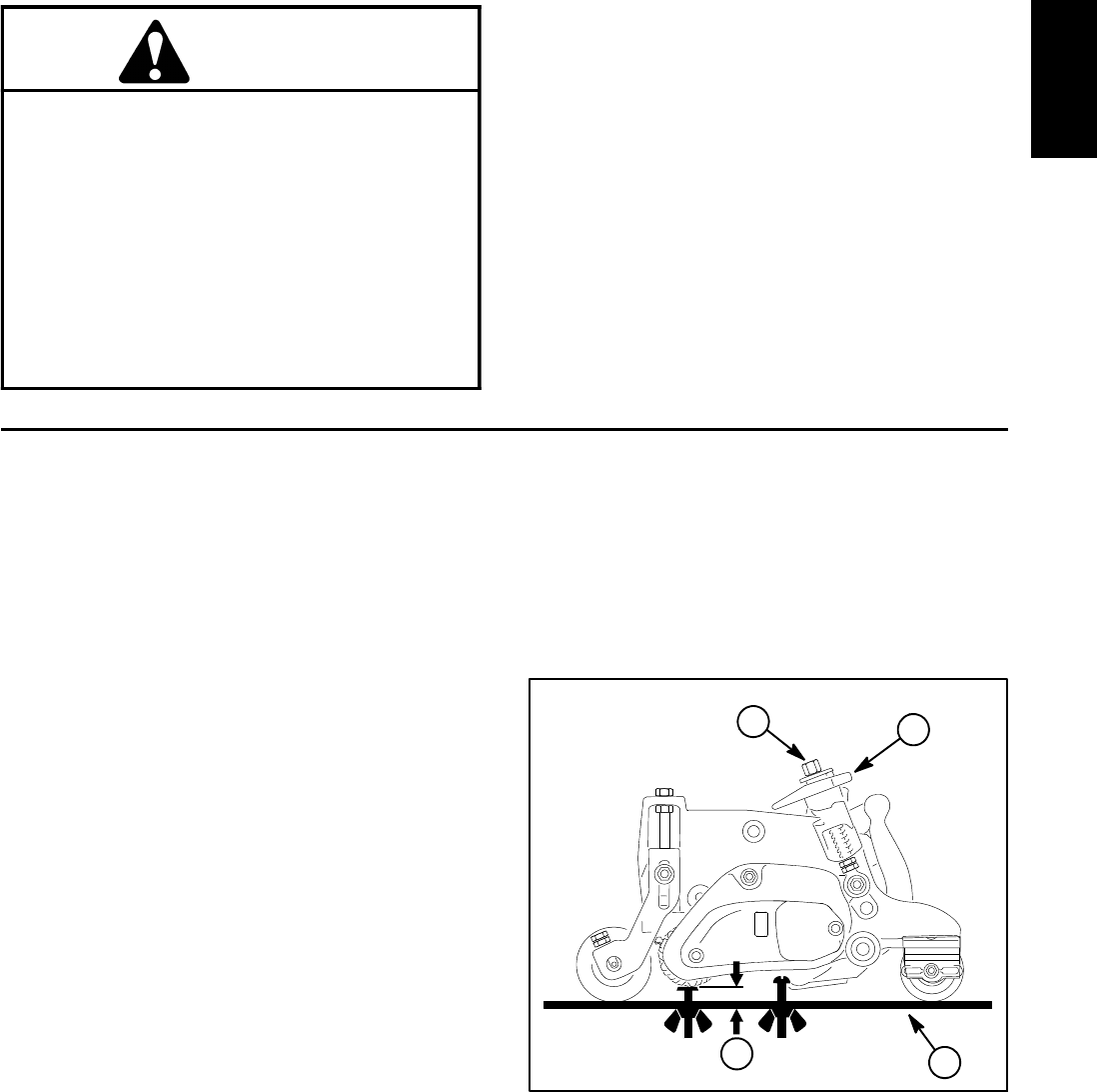
Reelmaster 5010- H GroomerPage 8 - 7
Adjustments
CAUTION
Never work on the groomer with the engine
running. Always stop the engine, remove the
key from the ignition switch and wait for all
machine movement to stop before working on
the groomer.
Also, before installing, removing or working on
the cutting units, disconnect the cutting units
from the electrical power supply by separating
the cutting unit power disconnect connector
(see 48 VDC Battery Disconnect in the General
Information section of this chapter).
Groomer Height/Depth Adjustment
NOTE: Grooming is performed above the soil level.
When adjusting groomer height/depth, groomer blades
should never penetrate the soil.
1. Parkmachineonacleanand level surface, lower
cutting units completely to the ground, stop engine, en-
gage parking brake and remove key from the ignition
switch.
2. To prevent unexpected reel motor operation, discon-
nect motors from the electrical power supply by unplug-
ging the 48 VDC battery disconnect (see 48 VDC
Battery Disconnect in the General Information section of
this chapter).
3. Make sure rollers are clean and cutting unit is set to
the desired height- of- cut (see Cutting Unit Operator’s
Manual).
4. Place the groomer reel in the grooming (lowered)
position by rotating the quick- up levers toward the front
of the cutting unit (Fig. 5).
NOTE: Improper or over- aggressive use of the groom-
er (e.g. too deep or too frequent grooming) may cause
unnecessary stress on the turf leading to severe turf
damage. Use the groomer cautiously.
NOTE: Use the gauge bar assembly (see Special Tools
in this chapter) to determine groomer height.
5. Measure the distance from the lowest tip of the
groomer blade to the working surface. Turn groomer
height adjuster to raise or lower the groomer blade tip to
the desired height (Fig. 5).
6. Repeat step 5 on the opposite end of the groomer.
Then, recheck setting on the first side of groomer.
Height setting on both ends of groomer should be identi-
cal.
7. Plug the 48 VDC battery disconnect back in before
operating the machine.
1. Groomer height adjuster
2. Quick- up lever
3. Gauge bar assembly
4. Groomer height
Figure 5
2
1
43
Groomer
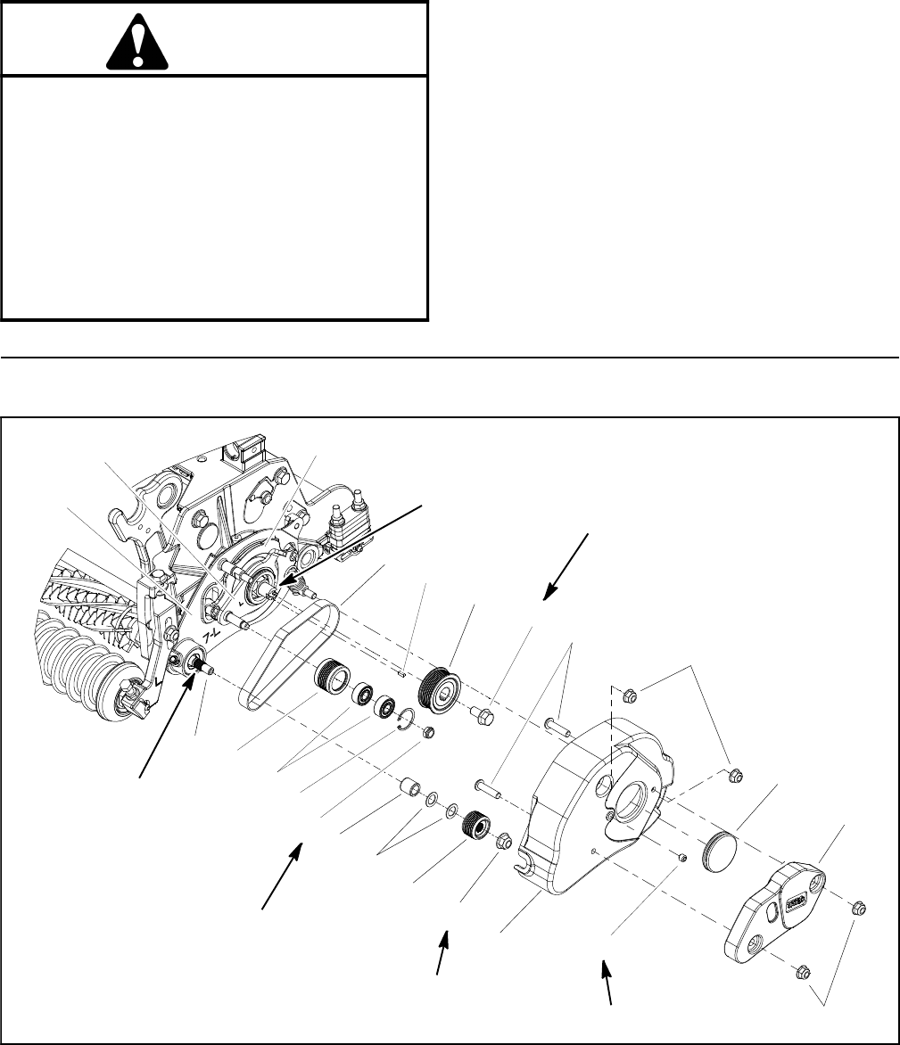
Reelmaster 5010- HGroomer Page 8 - 8
Service and Repairs
CAUTION
Never work on the groomer with the engine
running. Always stop the engine, remove the
key from the ignition switch and wait for all
machine movement to stop before working on
the groomer.
Also, before installing, removing or working on
the cutting units, disconnect the electrical pow-
er supply by separating the 48 VDC battery dis-
connect (see 48 VDC Battery Disconnect in the
General Information section of this chapter).
Groomer Drive Assembly
Figure 6
1. Flange nut (2 used)
2. Groomer cover
3. Groomer drive belt
4. Flange head screw
5. Drive pulley
6. Square key
7. Lock nut
8. Retaining ring
9. Ball bearing (2 used)
10. Idler pulley
11. Flange nut
12. Drive pulley
13. Washer (for pulley alignment)
14. Spacer
15. Groomer drive shaft
16. Groomer weight
17. Screw (2 used)
18. Flange nut (2 used)
19. Grommet
20. Set screw
21. Groomer plate
22. Pivot hub
23. Idler plate
4
3
1
2
9
10
8
5
6
11
12
13
14
15
16
17
19
7
18
20
27 to 33 ft- lb
(37to44N-m)
Loctite #242
27 to 33 ft- lb
(37to44N-m)
75 to 90 in- lb
(8.5 to 10.1 N- m)
Antiseize
Lubricant
Antiseize
Lubricant
21
23 22 7” CUTTING UNIT SHOWN
In Key Slot
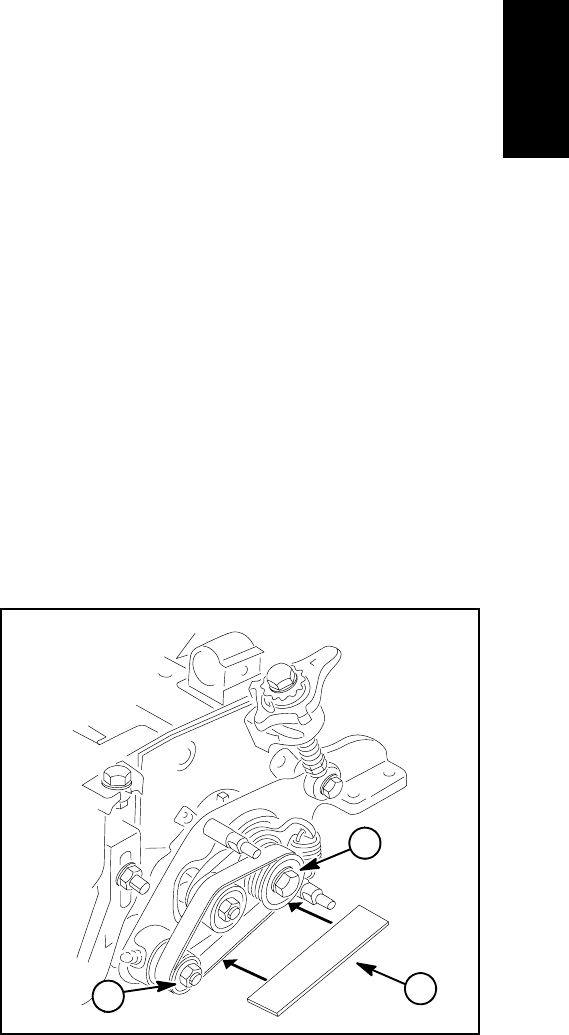
Reelmaster 5010- H GroomerPage 8 - 9
NOTE: The groomer drive is located on the opposite
side of the cutting unit from the cutting reel motor. Figure
6 shows components used when the groomer drive is on
theleftsideofthecuttingunit.
Disassembly (Fig. 6)
1. Parkmachineonacleanand level surface, lower
cutting units completely to the ground, stop engine, en-
gage parking brake and remove key from the ignition
switch.
2. To prevent unexpected reel motor operation, discon-
nect motors from the electrical power supply by unplug-
ging the 48 VDC battery disconnect (see 48 VDC
Battery Disconnect in the General Information section of
this chapter).
NOTE: If cutting unit is equipped with powered rear roll-
er brush, removal of roller brush components will be
necessary to replace groomer drive belt (see Rear
Roller Brush (Optional) in the Service and Repairs sec-
tion of Chapter 7 - Cutting Units).
NOTE: When removing groomer cover, groomer
weight does not have to be removed from cover.
3. Remove two (2) flange nuts that secure groomer
cover, then remove cover.
4. Remove groomer drive belt tension by pivoting idler
plate and pulley using a wrench on pulley nut. Slip
groomer drive belt off pulleys. Carefully release idler
plate and pulley.
5. As needed, remove drive pulley (item 5), driven pul-
ley (item 12) and idler pulley (item 10) using Figure 6 as
a guide.
NOTE: See Groomer Plate Assembly in this section for
information on removing and installing groomer plate
(item 21), pivot hub (item 22) or idler plate (item 23).
Assembly (Fig. 6)
1. If idler pulley (item 10) was removed, make sure that
bearings are in good condition before installing pulley.
Slide pulley assembly onto idler plate shaft and secure
with flange nut. Torque flange nut from 75 to 90 in- lb
(8.5 to 10.1 N- m).
NOTE: To prevent groomer shaft from turning when
installing driven pulley, use wrench on groomer shaft
flats.
2. If driven pulley (item 10) was removed, make sure
that spacer and washer(s) are on groomer shaft. Apply
antiseize lubricant to splines of drive pulley, slide pulley
onto groomer shaft and secure with flange nut. Torque
flange nut from 27 to 33 ft- lb (37 to 44 N- m).
NOTE: To prevent cutting reel from turning when instal-
ling drive pulley, block cutting reel with piece of wood.
3. If drive pulley (item 5) was removed, apply antiseize
lubricant to key slot in shaft. Place square key into shaft
slot. Slide drive pulley onto shaft and secure with flange
head screw. Torque screw from 27 to 33 ft- lb (37 to 44
N-m).
4. Check pulley alignment by laying a straight edge
along the outer face of the drive pulley (Fig. 7). Drive and
driven pulleys should be in line within 0.030” (0.76 mm).
If necessary, align pulleys by removing driven pulley and
installing or removing washer(s) (item 13 in Figure 6) be-
tween pulley and pulley spacer. Do not use idler pulley
to check pulley alignment.
5. Install drive belt to drive pulley, idler pulley and driven
pulley observing correct belt routing (Fig. 7). Make sure
that groomer drive belt is above idler pulley after belt in-
stallation and also that the ribs on drive belt are seated
in grooves in each pulley.
6. Install groomer cover and secure with two (2) flange
nuts.
7. Plug the 48 VDC battery disconnect back in before
operating the machine.
1. Drive pulley
2. Driven pulley
3. Straight edge
Figure 7
2
1
3
Groomer
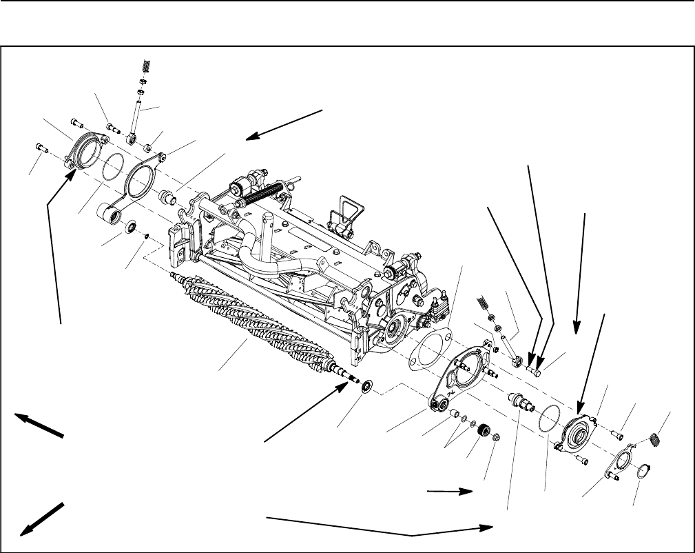
Reelmaster 5010- HGroomer Page 8 - 10
Groomer Reel and Groomer Plate Assembly
Figure 8
1. Groomer reel
2. Pulley spacer
3. Washer (for pulley alignment)
4. Driven pulley
5. Flange nut
6. Excluder seal (2 used)
7. O- ring
8. Idler plate
9. Extension spring
10. Retaining ring
11. Socket head screw (2 used per hub)
12. Pivot hub (drive side)
13. O- ring (1 used per hub)
14. Groomer plate (drive side)
15. Groomer shim
16. Groomer drive shaft
17. Pivot hub (non- drive side)
18. Groomer plate (non- drive side)
19. Reel threaded insert
20. Shoulder bolt
21. LH ball joint rod
22. Spacer
23. RH ball joint rod
24. Spacer
FRONT
RIGHT Antiseize
Lubricant
Antiseize
Lubricant
4
3
1
2
9
10
11
5
6
12
7
17
18 19
8
13
14
15
16
6
11
13
85 to 95 ft- lb
(115 to 128 N- m)
Loctite #242
85 to 95 ft- lb
(115 to 128 N- m)
Loctite #242
27 to 33 ft- lb
(37 to 44 N- m)
Antiseize
Lubricant 20
21
22
23
24
20
Antiseize
Lubricant
17 to 21 ft- lb
(23to28N-m)
7” CUTTING UNIT SHOWN
Loctite #242
NOTE: The groomer reel drive is located on the oppo-
site side of the cutting unit from the cutting reel motor.
Figure 8 shows components used when the groomer
reel drive is on the left side of the cutting unit.
Removal (Fig. 8)
1. Parkmachineonacleanand level surface, lower
cutting units completely to the ground, stop engine, en-
gage parking brake and remove key from the ignition
switch. Remove cutting unit from machine.
NOTE: If cutting unit is equipped with powered rear roll-
er brush, removal of roller brush components will be
necessary to service groomer plate assemblies (see
Rear Roller Brush (Optional) in the Service and Repairs
section of Chapter 7 - Cutting Units).
2. To remove groomer plate (item 14) from groomer
drive side of cutting unit:
A. Remove groomer belt cover, groomer drive belt,
drive pulley and driven pulley from cutting unit (see
Groomer Assembly in this section).
B. Slide washer(s) (item 3) and pulley spacer (item
2) from groomer shaft.
C. Remove shoulder bolt (item 20) that secures
quick- up ball joint rod to drive side groomer plate.
Locate and retrieve spacer from between ball joint
rod and groomer plate.
D. Disconnect idler extension spring (item 9) from
stud on groomer plate.
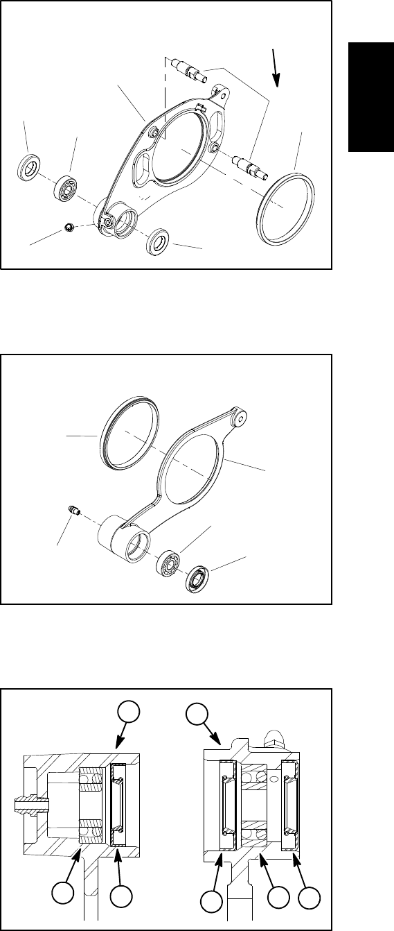
Reelmaster 5010- H GroomerPage 8 - 11
E. Remove two (2) socket head screws (item 11)
that secure pivot hub to cutting unit side plate.
F. Remove pivot hub with attached idler plate as-
sembly from cutting unit.
G. Support groomer shaft to prevent it from falling.
Carefully slide drive side groomer plate from groom-
er shaft and cutting unit. Remove groomer shim
(item 15).
3. Carefully pull the groomer reel from the non- drive
side groomer plate assembly.
4. To remove groomer plate (item 18) from groomer
non- drive side of cutting unit:
A. Remove shoulder bolt (item 20) that secures
quick- up ball joint rod to non- drive side groomer
plate. Locate and retrieve spacer from between ball
joint rod and groomer plate.
B. Remove two (2) socket head screws (item 11)
that secure pivot hub to cutting unit side plate.
C. Remove pivot hub from cutting unit.
D. Support groomer shaft to prevent it from falling.
Carefully slide non- drive side groomer plate from
groomer shaft and cutting unit.
5. Inspect seals, bearings and bushings in groomer
plates. Remove and discard damaged components.
NOTE: See Groomer Reel Service in this section for in-
formation about groomer reel disassembly and assem-
bly.
Installation (Fig. 8)
1. If seals, bearings or bushing was removed from ei-
ther of the groomer plates, install new components not-
ing proper orientation as shown in Figures 9, 10 and 11.
A. Press bushing into groomer plate until the bush-
ing contacts the shoulder in the groomer plate bore.
B. Pack bearings with grease before installation.
C. Press bearings into groomer plate so that bear-
ings contact shoulder in groomer plate bore.
D. Install grease seals so that seal lips are posi-
tioned toward the groomer blade location. Seals
should be flush with surface of groomer plate.
E. If groomer studs were removed from drive side
groomer plate and studs are being reinstalled, apply
Loctite #242 (or equivalent) to threads of studs. New
studs have patchlock on threads. Install studs into
groomer plate and torque from 14 to 18 ft- lb (19 to
24 N- m).
1. Groomer plate
2. Bushing
3. Seal
4. Bearing
5. Groomer stud
6. Grease fitting
Figure 9
1
2
3
4
5
6
3
14 to 18 ft- lb
(19 to 24 N- m)
DRIVE SIDE GROOMER PLATE
1. Groomer plate
2. Bushing
3. Seal
4. Bearing
5. Grease fitting
Figure 10
1
2
3
4
5
NON- DRIVE SIDE GROOMER PLATE
1. Drive side groomer plate
2. Non- drive groomer plate
3. Bearing
4. Grease seal
Figure 11
21
43
4
34
Groomer
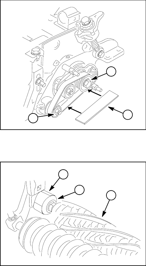
Reelmaster 5010- HGroomer Page 8 - 12
2. If removed, install groomer plate (item 18) to groom-
er non- drive side of cutting unit:
A. Position non- drive side groomer plate to cutting
unit side plate.
B. Slide O- ring onto pivot hub and then apply anti-
seize lubricant onto pivot hub flange. Position pivot
hub to groomer plate and cutting unit.
C. Secure pivot hub to cutting unit side plate with two
(2) socket head screws (item 11). Make sure that
groomer plate rotates freely after installation.
D. Apply antiseize lubricant to shoulder area of
shoulder bolt that secures quick- up ball joint rod to
non- drive side groomer plate and apply Loctite #242
(or equivalent) to threads of shoulder bolt. Position
spacer between ball joint rod and groomer plate. In-
stall shoulder bolt and torque from 17 to 21 ft- lb (23
to 28 N- m).
3. Make sure that O- ring (item 7) is on groomer reel
shaft and is lightly greased. Also, apply a light coat of
grease to lip of seal in installed groomer plate.
4. Make sure that excluder seals (item 6) and lightly
greased O- ring (item 7) are positioned on groomer
shaft. The excluder seal lips should be toward the end
of the groomer shaft. Apply a film of grease onto exclud-
er seal lips.
5. Carefully slide the groomer reel into the non- drive
side groomer plate assembly taking care to not damage
seals in groomer plate assembly.
6. Carefully install groomer plate (item 14) to groomer
drive side of cutting unit:
A. Apply a light coat of grease to lips of seals in
groomer plate.
B. Position groomer shim to cutting unit side plate.
Carefully position drive side groomer plate onto
groomer shaft and slide to cutting unit.
C. Slide O- ring onto pivot hub and then apply anti-
seize lubricant onto pivot hub flange. Position pivot
hub with attached idler plate assembly to cutting unit
side plate and secure with two (2) socket head
screws (item 11). Make sure that groomer shim has
not shifted and that groomer plate rotates freely after
installation.
D. Connect extension spring (item 9) to stud on
groomer plate. Make sure that spring is in the stud
groove and that spring hook is positioned toward the
drive pulley location.
E. Apply antiseize lubricant to shoulder area of
shoulder bolt that secures quick- up ball joint rod to
drive side groomer plate and apply Loctite #242 (or
equivalent) to threads of shoulder bolt. Position
spacer between ball joint rod and groomer plate. In-
stall shoulder bolt and torque from 17 to 21 ft- lb (23
to 28 N- m).
F. Slide pulley spacer (item 2) and washer(s) (item
3) onto groomer shaft.
G. Install drive pulley, driven pulley and groomer
drive belt to cutting unit (see Groomer Assembly in
this section). Make sure that fasteners are correctly
torqued. Also, make sure that drive and driven pulley
alignment is checked and adjusted if necessary. In-
stall groomer belt cover.
1. Drive pulley
2. Driven pulley
3. Straight edge
Figure 12
2
1
3
1. Groomer plate
2. Excluder seal
3. Groomer reel
Figure 13
2
1
3

Reelmaster 5010- H GroomerPage 8 - 13
7. Check that excluder seals just touch groomer plate
assembly (Fig. 13). Reposition excluder seals on
groomer shaft if needed. Excluder seal ID should be lo-
cated on groomer shaft surface that is recessed slightly.
8. Check groomer reel height and mower height- of- cut
settings. Adjust as needed.
9. Lubricate groomer bearings.
10.Install cutting unit back on machine.
NOTE: After greasing groomer bearings, operate
groomer for thirty (30) seconds, stop machine and wipe
excess grease from groomer shaft and seals.
Groomer
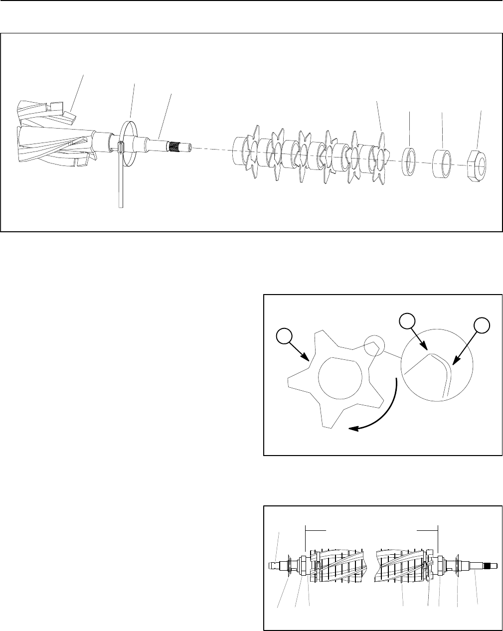
Reelmaster 5010- HGroomer Page 8 - 14
Groomer Reel Service
Figure 14
1. Groomer shaft
2. Lock nut (2 used)
3. Spacer (thick) (41 used)
4. Spacer (thin) (2 used)
5. Groomer blade (40 used)
6. Broomer brush (5 used)
7. Broomer strap (4 used)
43
1
2
5
7
6
Inspect groomer reel blades frequently for damage and
wear. Straighten bent blades with a pliers. Either replace
worn blades or reverse the blades to put the sharpest
blade edge forward (Fig. 15). Blades that are rounded
to the midpoint of the blade tip must be reversed or re-
placed for best groomer performance.
Disassembly (Fig. 14)
1. Remove groomer reel from cutting unit (see Groom-
er Reel in this section).
2. Remove excluder seals from groomer reel.
3. If groomer reel is equipped with broomer kit, remove
straps and broomer brushes from reel.
4. Remove lock nut from either end of the shaft.
5. Remove spacers and blades from groomer shaft. If
needed, remove second lock nut from shaft.
Assembly (Fig. 14)
1. Install lock nut on drive end of groomer shaft. Place
thick spacer, thin spacer and then first blade on shaft.
2. Alternately install thick spacers and blades making
sure that all blades are separated by a spacer.
3. When all blades have been installed, place thin
spacer and final thick spacer on shaft and then thread
second lock nut onto the shaft. Center blades on shaft
with lock nuts.
1. Groomer blade
2. Sharp edge
3. Dull (rounded) edge
Figure 15
ROTATION
GROOMER
3
2
1
1. Groomer reel shaft
2. Groomer blade (40 used)
3. Thick spacer (41 used)
4. Thin spacer (2 used)
5. Lock nut (2 used)
6. Excluder seal
7. O- ring groove
Figure 16
CENTERED ON SHAFT
1234556 6
7
Reelmaster 5010- H GroomerPage 8 - 15
4. Using wrench on shaft flats to prevent shaft from
turning, torque second lock nut from 375 to 425 in- lb
(43to48N-m). After torquing lock nut, spacers should
not be free to rotate and groomer blades should be cen-
teredonshaft.
5. If groomer reel is equipped with broomer kit, position
broomer brushes to reel blades and secure with straps.
Straps should be wrapped around the groomer assem-
bly as shown in Figure 17 and between blades 1- 2,
14- 15, 28- 29 and 41- 42. Pull straps tight and cut off
strap extension approximately 1/4” (6 mm) beyond re-
tainer.
6. Apply a film of grease onto excluder seal lips and
slide seals onto groomer shaft. Excluder seal ID should
belocatedongroomershaft surface that is recessed
slightly.
7. Install O- ring on non- drive end of groomer shaft.
8. Install groomer reel back on cutting unit (see Groom-
er Reel in this section).
9. Check groomer reel height and mower height- of- cut
settings. Adjust as needed.
10.Lubricate groomer bearings.
11.Install cutting unit back on machine.
NOTE: After greasing groomer bearings, operate
groomer for thirty (30) seconds, stop machine and wipe
excess grease from groomer shaft and seals.
1. Groomer shaft 2. Broomer strap
Figure 17
1
2
2
2
2
Groomer
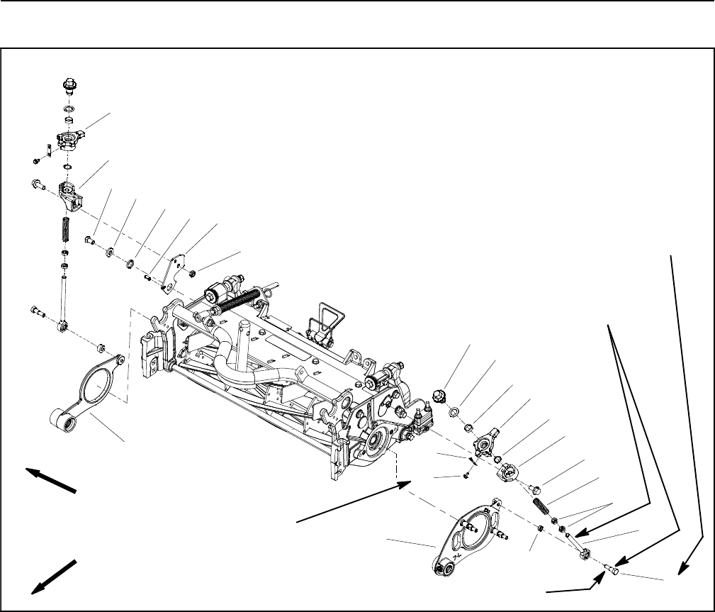
Reelmaster 5010- HGroomer Page 8 - 16
Height Adjuster Assembly
Figure 18
1. Groomer plate (drive side)
2. Shoulder bolt
3. Ball joint rod
4. Jam nut
5. Compression spring
6. Flange head screw
7. LH lower ramp
8. External snap ring
9. LH upper ramp
10. Bushing
11. Flat washer
12. Groomer adjuster
13. Detent spring
14. Washer head screw
15. Spacer
16. Groomer plate (non- drive side)
17. RH lower ramp
18. RH upper ramp
19. Cap screw
20. Spacer
21. Spacer
22. Roll pin
23. Groomer plate
24. Lock nut
30 to 40 in- lb
(3.4 to 4.5 N- m)
Antiseize
Lubricant
4
3
1
2
9
10
11
8
5
6
7
12
13
14
17 to 21 ft- lb
(23to28N-m)
15
16
17
18
19 20 21 22 23
24
FRONT
RIGHT
7” CUTTING UNIT SHOWN
Loctite #242
NOTE: The groomer reel drive is located on the oppo-
site side of the cutting unit from the cutting reel hydraulic
motor. Figure 18 shows components used when the
groomer reel drive is on the left side of the cutting unit.
Disassembly (Fig. 18)
1. Parkmachineonacleanand level surface, lower
cutting units completely to the ground, stop engine, en-
gage parking brake and remove key from the ignition
switch.
2. To prevent unexpected reel motor operation, discon-
nect motors from the electrical power supply by unplug-
ging the 48 VDC battery disconnect (see 48 VDC
Battery Disconnect in the General Information section of
this chapter).
3. Disassemble height adjuster as needed using Figure
18 as a guide.
4. Clean all height adjuster components and inspect for
wear or damage. Replace all worn or damaged compo-
nents.
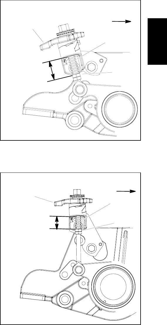
Reelmaster 5010- H GroomerPage 8 - 17
Assembly (Fig. 18)
1. Assemble height adjuster using Figure 18 as a guide
noting the following items:
NOTE: On 7” cutting units, the ball joint rod on the cut-
ting unit motor side is longer that the ball joint rod used
on the groomer drive side of the cutting unit. On 5” cut-
ting units, the ball joint rods are identical.
A. If bushing (item 10) was removed from upper
ramp, press new bushing into housing fully to the
shoulder in the bore.
B. If jam nuts (item 4) were removed from ball joint
rod, apply antiseize lubricant to threads of rod where
jam nuts will be positioned. Install jam nuts so that
distance from top of ball joint rod to bottom of lower
nut is from 3.190” to 3.310” (8.1 to 8.4 cm).
C. Apply antiseize lubricant to threads of ball joint
rod before installing groomer adjuster (item 12) onto
rod.
D. If detent spring (item 13) was removed, secure
detent spring to upper ramp with washer head screw.
Torque screw from 30 to 40 in- lb (3.4 to 4.5 N- m).
2. Apply antiseize lubricant to shoulder area of shoul-
der bolt that secures ball joint rod to groomer plate and
apply Loctite #242 (or equivalent) to threads of shoulder
bolt. Position spacer between ball joint rod and groomer
plate. Install shoulder bolt and torque from 17 to 21 ft- lb
(23to28N-m).
3. Check groomer reel height and adjust as needed.
4. After groomer height has been adjusted, adjust loca-
tion of jam nuts so compression spring length is from
1.320” to 1.440” (3.4 to 3.6 mm) when the groomer
handle is in the disengaged position (handle toward rear
of cutting unit) (shown in Fig. 19 For 5” cutting unit and
Fig. 20 For 7” cutting unit).
5. Plug the 48 VDC battery disconnect back in before
operating the machine.
1. Groomer handle
2. Compression spring
3. Upper jam nut
Figure 19
1.320” to 1.440”
(3.4 to 3.6 mm)
FRONT
1
2
3
5” CUTTING UNIT
Figure 20
1
2
3
1.320” to 1.440”
(3.4 to 3.6 mm)
1. Groomer handle
2. Compression spring
3. Upper jam nut
FRONT
7” CUTTING UNIT
Groomer
Reelmaster 5010- HGroomer Page 8 - 18
This page is intentionally blank.

Reelmaster 5010- H Foldout DrawingsPage 9 - 1
Chapter 9
Foldout Drawings
Table of Contents
ELECTRICAL DRAWING DESIGNATIONS 2.......
HYDRAULIC SCHEMATIC 3.....................
ELECTRICAL SCHEMATIC 4....................
WIRE HARNESS DRAWINGS
Main Wire Harness Drawing 6..................
Main Wire Harness Diagram 7..................
Seat Wire Harness Drawing 8..................
Seat Wire Harness Diagram 9..................
Foldout
Drawings

Reelmaster 5010- HFoldout Drawings Page 9 - 2
Electrical Drawing Designations
The following abbreviations are used for wire harness
colors on the electrical schematics and wire harness
drawings in this chapter.
ABBREVIATION COLOR
BK BLACK
BR or BN BROWN
BU BLUE
GN GREEN
GY GRAY
OR ORANGE
PK PINK
RorRD RED
TTAN
VIO VIOLET
WorWH WHITE
YorYE YELLOW
Numerous harness wires used on Reelmaster ma-
chines include a line with an alternate color. These wires
are identified with the wire color and line color with either
a / or _ separating the color abbreviations listed above
(e.g. R/BK is a red wire with a black line, OR_BK is an
orange wire with a black line).
NOTE: The electrical harness drawings in this chapter
identify both the wire color and the wire gauge. For ex-
ample, 16 BK on a harness diagram identifies a 16
gauge wire that has a black insulator.
NOTE: A splice used in a wire harness will be identified
on the wire harness diagram by SP. The manufacturing
number of the splice is also identified on the wire har-
ness diagram (e.g. SP01 is splice number 1).
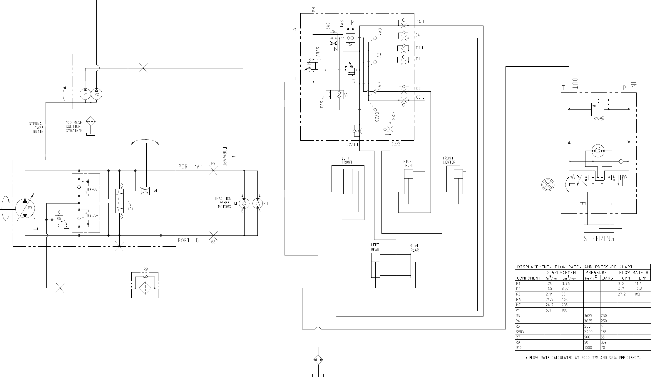
Page 9 - 3
Hydraulic Schematic
Reelmaster 5010- H
LIFT
CONTROL
MANIFOLD
POWER
STEERING
VALVE
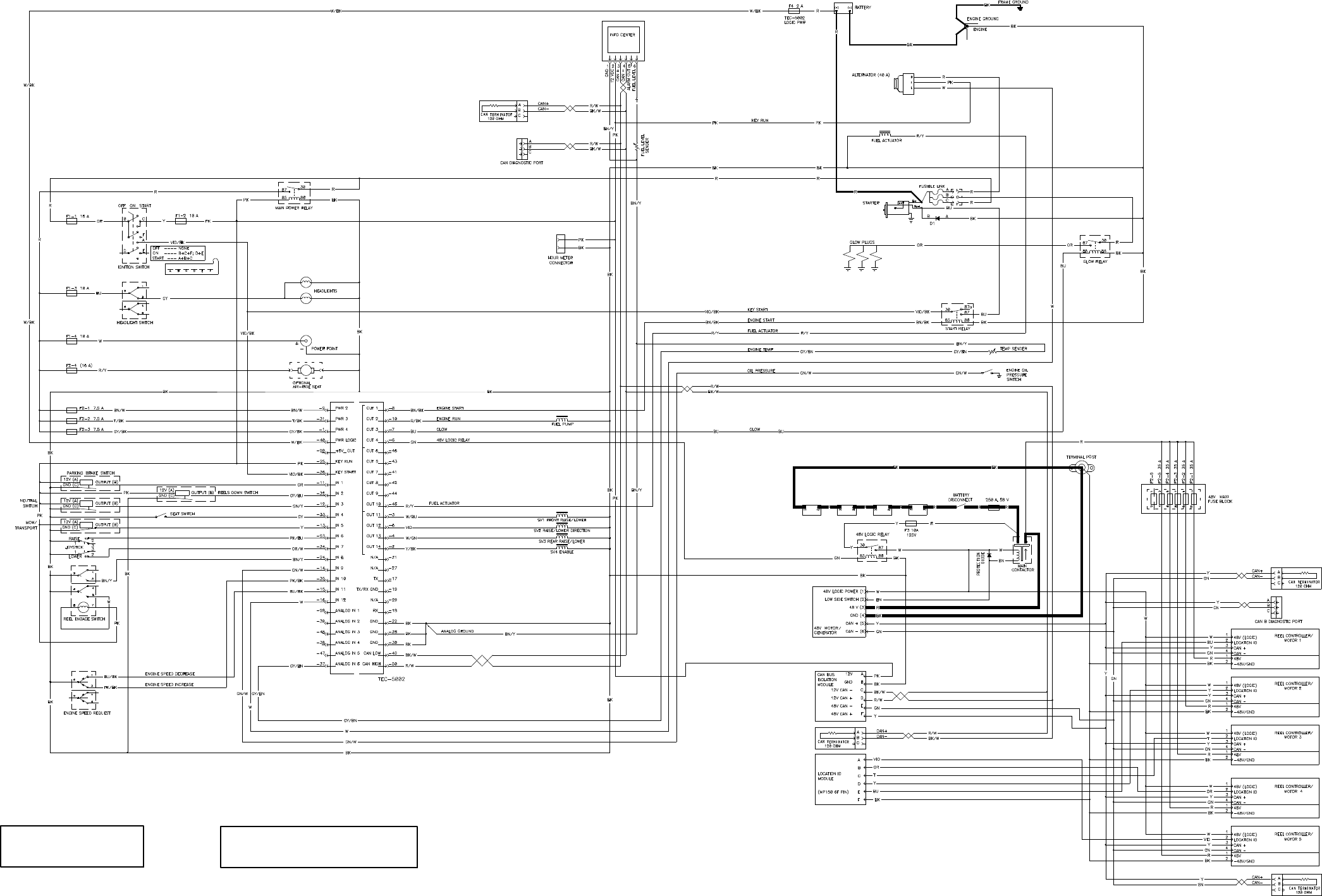
Page 9 - 4
Electrical Schematic
Reelmaster 5010- H
All relays and solenoids
are shown as de- energized.
All ground wires are black. WIRE COLOR ABBREVIATIONS.
NOTE: REFER TO ELECTRICAL DRAWING
DESIGNATIONS IN THIS CHAPTER FOR
Page 9 - 5
This page is intentionally blank.
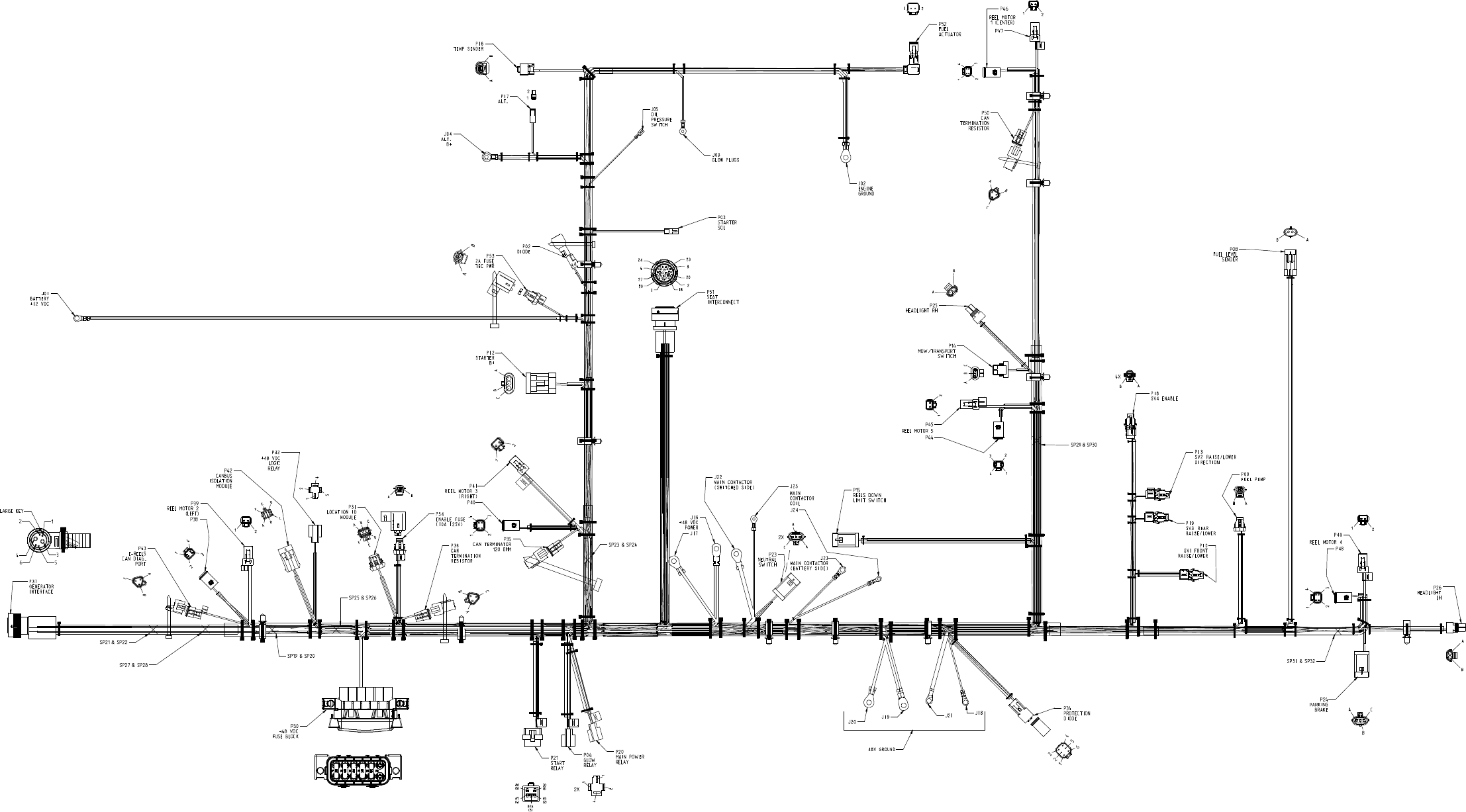
Page 9 - 6
Reelmaster 5010- H
Main Wire Harness Drawing
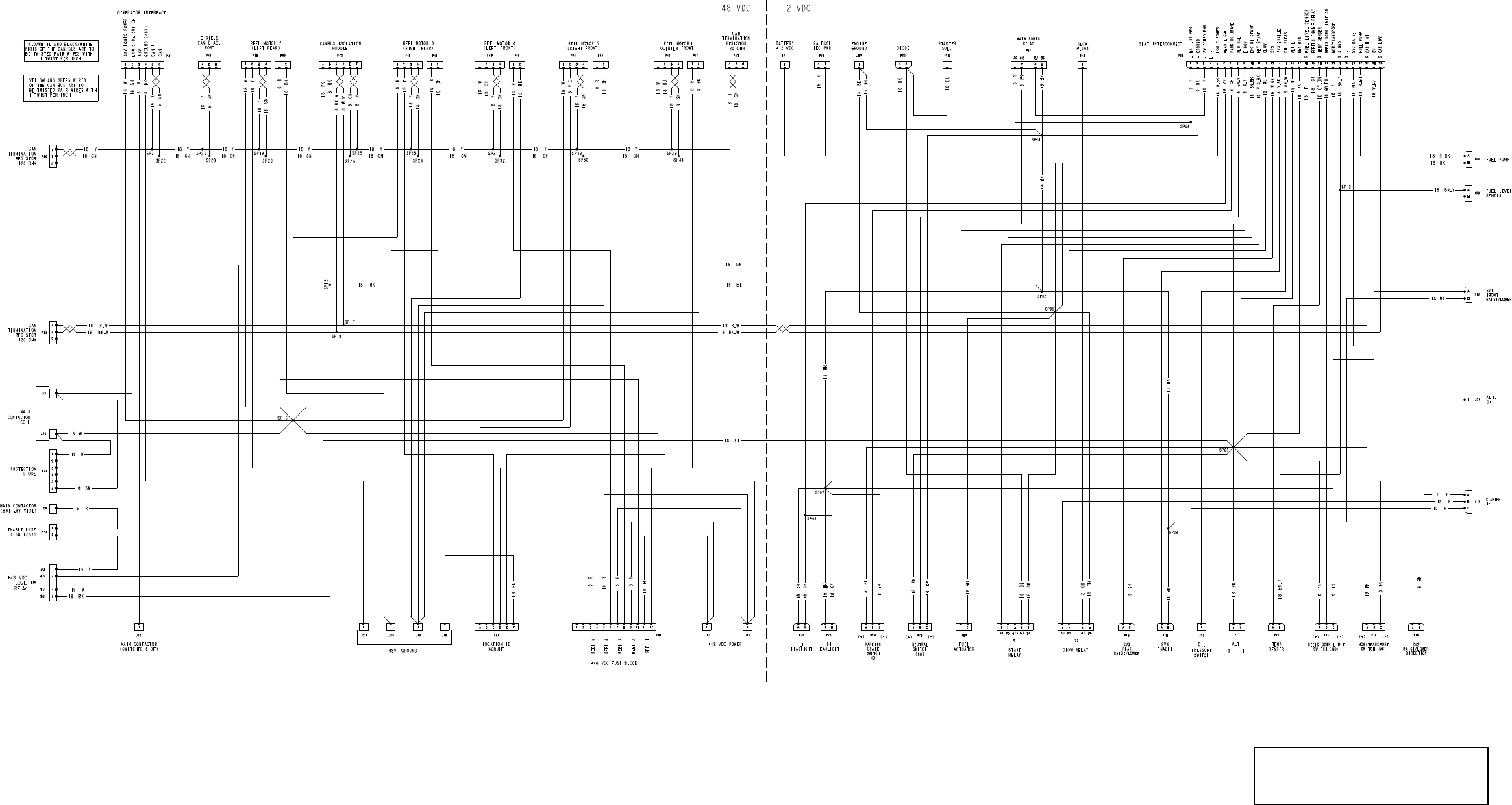
Page 9 - 7
Reelmaster 5010- H
Main Wire Harness Diagram
DRAWING DESIGNATIONS IN THIS CHAPTER
NOTE: THIS DRAWING IDENTIFIES WIRE GAUGE
SIZE AND WIRE COLOR. REFER TO ELECTRICAL
FOR ADDITIONAL INFORMATION.
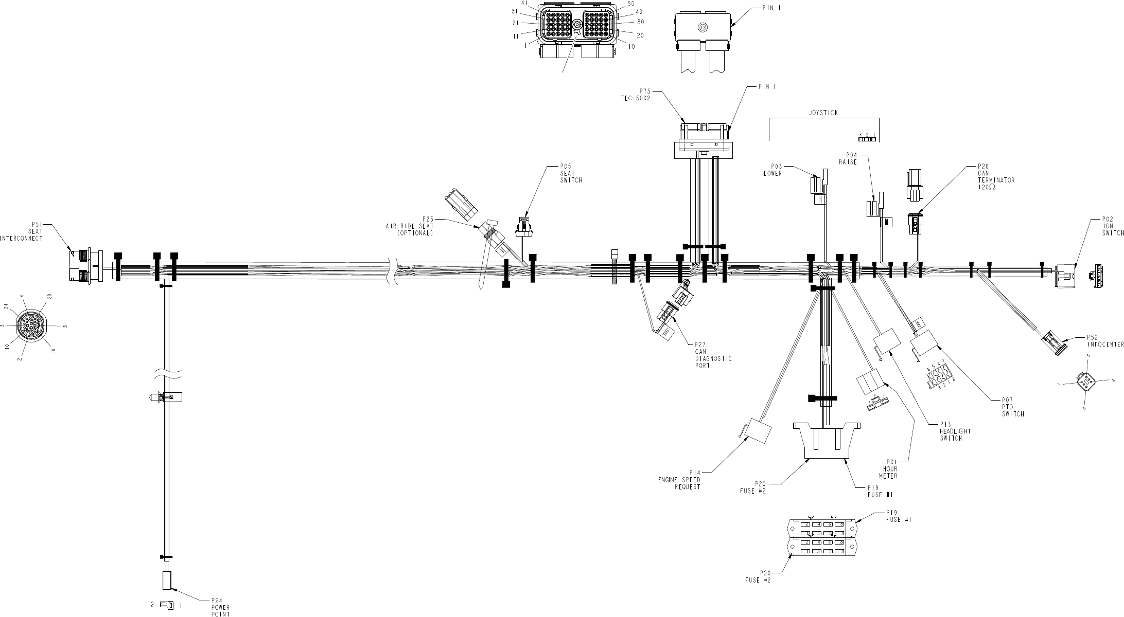
Page 9 - 8
Reelmaster 5010- H
Seat Wire Harness Drawing
NOTE CLOCK POSITION
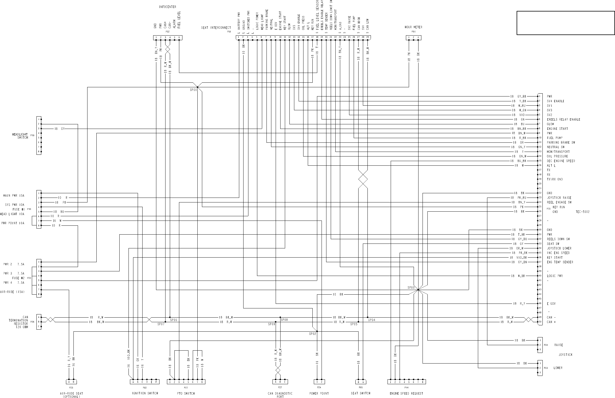
Page 9 - 9
Reelmaster 5010- H
Seat Wire Harness Diagram
DRAWING DESIGNATIONS IN THIS CHAPTER
NOTE: THIS DRAWING IDENTIFIES WIRE GAUGE
SIZE AND WIRE COLOR. REFER TO ELECTRICAL
FOR ADDITIONAL INFORMATION.
