Toro 74360 (280000001 280999999) User Manual RIDING MOWER Manuals And Guides 1012312L
User Manual: Toro 74360 (280000001-280999999) 74360 (280000001-280999999) TORO RIDING MOWER - Manuals and Guides View the owners manual for your TORO RIDING MOWER #74360280000001280999999. Home:Lawn & Garden Parts:Toro Parts:Toro RIDING MOWER Manual
Open the PDF directly: View PDF ![]() .
.
Page Count: 94
Count on it.
mmmm
0
0
Form No. 3358-918 Rev A
TimeCutter_ Z4200 Riding Mower
Model No. 74360--Serial No. 280000001 and Up
G007083
Register at www.Toro.com. Original Instructions (EN)
CALIFORNIA
Proposition 65 Warning
The engine exhaust from this product
contains chemicals known to the State of
California to cause cancer, birth defects,
or other reproductive harm.
Important: This engine is not equipped with a
spark arrester muffler. It is a violation of California
Public Resource Code Section 4442 to use or operate
the engine on any forest-covered, brush-covered, or
grass-covered land. Other states or federal areas
may have similar laws.
This spark ignition system complies with Canadian
ICES-002.
The enclosed Engine Owner's Manual is supplied
for information regarding the US Environmental
Protection Agency (EPA) and the California
Emission Control Regulation of emission systems,
maintenance, and warranty. Replacements may be
ordered through the engine manufacturer.
For models with stated engine horsepower, the gross
horsepower of the engine was laboratory rated by the
engine manufacturer in accordance with SAE J1940.
As configured to meet safeb, emission, and operating
requirements, the actual engine horsepower on this class
of lawn mower will be significantly lower.
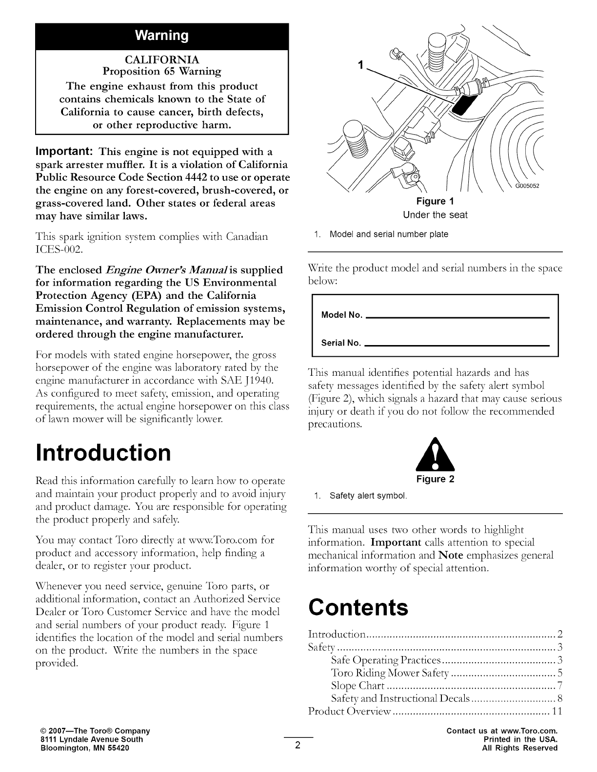
Figure 1
Under the seat
1. Model and serial number plate
Write the product model and serial numbers in the space
below:
Model No.
Serial No.
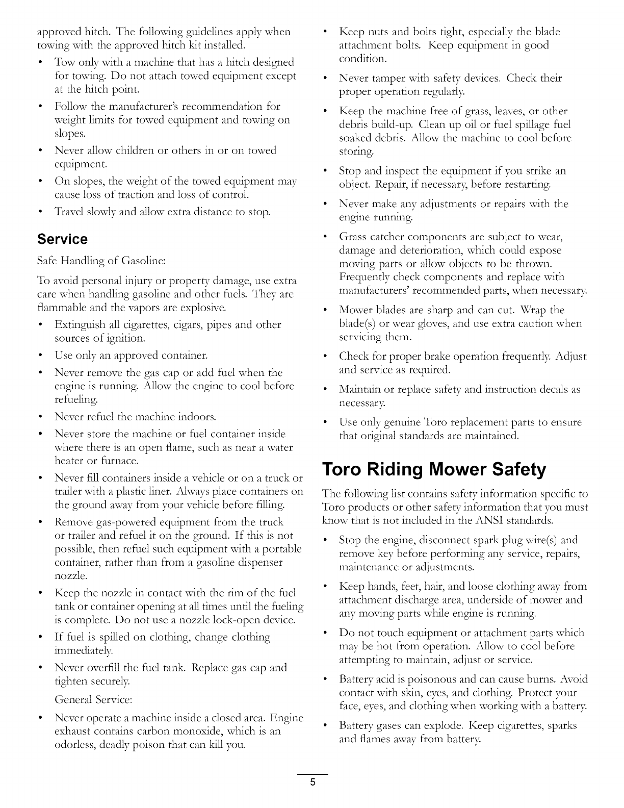
This manual identifies potential hazards and has
safeb Tmessages identified by the safe_ Talert symbol
(Figure 2), which signals a hazard that may cause serious
injury or death if you do not follow the recommended
precautions.
Introduction
Figure 2
1. Safety alertsymbol.
This manual uses two other words to highlight
information. Important calls attention to special
mechanical information and Note emphasizes general
information worthy of special attention.
Read this information carefully to learn how to operate
and maintain your product properly and to avoid injury
and product damage. You are responsible for operating
the product properly and safely.
You may contact Toro directly at v_-,w,vToro.com for
product and accessory information, help finding a
dealer, or to register your product.
Whenever you need service, genuine Toro parts, or
additional information, contact an Authorized Service
Dealer or Toro Customer Service and have the model
and serial numbers of your product read> Figure 1
identifies the location of the model and serial numbers
on the product. Write the numbers in the space
provided.
Contents
Introduction ................................................................. 2
Safe_ _........................................................................... 3
Safe Operating Practices ....................................... 3
Toro Riding Mower Safety .................................... 5
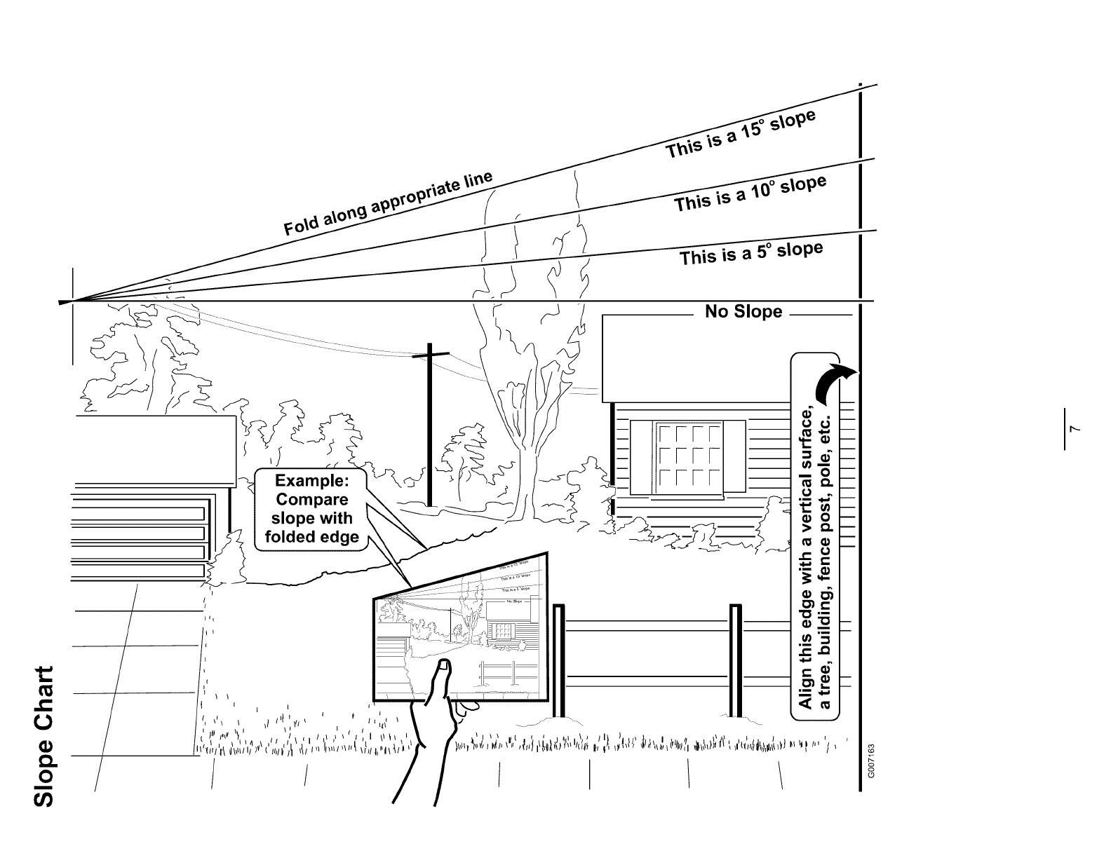
Slope Chart .......................................................... 7
Safety and Instructiomfl Decals ............................. 8
Product Overview. ..................................................... 11
©2007--The Toro® Company
8111 Lyndale Avenue South
Bloomington, MN 55420
Contact us at www.Toro.com.
Printed in the USA.
All Rights Reserved

Controls ............................................................. 12
Operation ................................................................... 13
Think Safety First ............................................... 13
Recommended Gasoline ..................................... 13
Chec_ng the Engine Oil Level ............................ 15
Starting the Engine ............................................. 15
Operating the Blades .......................................... 16
Stopping the Engine ........................................... 17
The Safety Interlock System ................................ 17
Driving Forward or Backward ............................. 18
Stopping the Machine ......................................... 18
Adjusting the Height of Cut ................................ 18
Positioning the Seat ............................................ 19
Adjusting the Motion Control Levers .................. 19
Pushing the Machine by Hand ............................. 19
Side Discharge .................................................... 20
Operating Tips ................................................... 20
Maintenance ............................................................... 22
Recommended Maintenance Schedule(s) ................ 22
Premaintenance Procedures .................................... 23
Raising the Seat .................................................. 23
Accessing the Battery ......................................... 23
Lubrication ............................................................. 23
Greasing the Bearings ......................................... 23
Engine Maintenance ............................................... 24
Servicing the Air Cleaner .................................... 24
Servicing the Engine Oil ..................................... 25
Servicing the Spark Plug ..................................... 27
Cleaning the Blower Housing .............................. 27
Fuel System Maintenance ....................................... 28
Replacing the Fuel Filter ..................................... 28
Electrical System Maintenance ................................ 29
Charging the Battery ........................................... 29
Servicing the Fuses ............................................. 30
Drive System Maintenance ..................................... 31
Chec_ng the Tire Pressure ................................. 31
Mower Maintenance ............................................... 32
Servicing the Cutting Blades ............................... 32
Leveling the Mower from Side-to-Side ................ 33
Adjusting the Front-to-Rear Blade Slope ............. 34
Removing the Mower ......................................... 35
Mower Belt Maintenance .................................... 36
Installing the Mower ........................................... 36
Replacing the Grass Deflector ............................. 37
Cleaning ................................................................. 38
Washing the Underside of the Mower .................. 38
Storage ....................................................................... 39
Cleaning and Storage .......................................... 39
Troubleshooting ......................................................... 40
Schematics ................................................................. 42
Safety
This machine meets or exceeds the B71.1-2003
specifications of the American National Standards
Institute, in effect at the time of production.
However, improper use or maintenance by the
operator or owner can result in injury. To reduce
the potential for injury, comply with these safety
instructions and always pay attention to the
safety alert symbol, which means CAUTION,
WARNING, or DANGER-"personal safety
instruction." Failure to comply with the instruction
may result in personal injury or death.
Safe Operating Practices
The following instructions are from ANSI standard
B71.1-2003.
This product is capable of amputating hands and
feet and throwing objects. Always follow all safety
instructions to avoid serious injury or death.
General Operation
• Read, understand, and follow all instructions in
the operator's manual and on the machine before
starting.
• Do not place hands or feet near rotating parts or
under the machine. Keep clear of the discharge
opening at all times.
• Allow only responsible adults who are familiar with
the instructions to operate the machine.
• Clear the area of objects such as rocks, toys, wire,
etc., which could be picked up and thrown by the
blade.
•Be sure the area is clear of other people before
mowing. Stop the machine if awone enters the area.
• Never carry passengers.
• Do not mow in reverse unless absolutely necessar 7
Akvays look down and behind before and while
bac_ng up.
• Be aware of the mower discharge direction and do
not point it at awone. Avoid discharging material
against a wall or obstruction. Material may ricochet
back toward the operator. Stop the blade(s) when
crossing gravel surfaces.
• Do not operate the machine without deflector,
discharge cover or entire grass collection system in
place and wor_ng.
• Be alert, slow down and use caution when ma_ng
turns. Look behind and to the side before changing
directions.

• Neverleavearunningmachineunattended.Ahvays
turn off blades,setparing brake,stopengine,and
removekeybeforedismounting.
• Turnoff bladeswhennot mowing.Stoptheengine
andwaitfor allpartsto cometo acompletestop
beforecleaningthemachine,removingthegrass
catcheroruncloggingthedischargechute.
• Operatethemachineonly in daylightor good
artificiallight.
• Do not operatethemachinewhileunderthe
influenceof alcoholor drugs.
• Watchfor trafficwhenoperatingnearor crossing
roadways.
• Useextracarewhenloadingor unloadingthe
machineinto atraileror truck.
Ahvaysweareyeprotectionwhenoperatingthe
mower.
• Dataindicatesthat operators,age60yearsand
above,areinvolvedin alargepercentageof riding
mower-relatedinjuries.Theseoperatorsshould
evaluatetheirabilityto operatetheridingmower
safelyenoughto protectthemseDesandothersfrom
seriousinjur>
• Ahvaysfollowtherecommendationsfor wheel
weightsor counterweights.
Slope Operation
Slopes are a major factor related to loss of control and
tip-over accidents, which can result in severe injury or
death. Operation on all slopes requires extra caution. If
you cannot back up the slope or if you fed uneasy on it,
do not mow it.
Do not mow slopes greater than 15 degrees.
Watch for ditches, holes, rocks, dips, and rises that
change the operating angle, as rough terrain could
overturn the machine.
• Choose a low ground speed so you will not have to
stop while operating on a slope.
• Do not mow slopes when grass is wet. Slippery
conditions reduce traction and could cause sliding
and loss of control.
• Ahvays keep the wheel motors engaged when going
down slopes.
• Reduce speed and use extreme caution on slopes.
• Do not make sudden turns or rapid speed changes.
• Remove or mark obstacles such as rocks, tree limbs,
etc. from the mowing area. Tall grass can hide
obstacles.
• Avoid sudden starts when mowing uphill because
the mower may tip backwards.
• Be aware that loss of traction may occur going
downhill. Weight transfer to the front wheels may
cause drive wheels to slip and cause loss of braMng
and steering.
• Ahvays avoid sudden starting or stopping on a
slope. If tires lose traction, disengage the blades and
proceed slowly off the slope.
• Use extreme care with grass catchers or other
attachments. These can change the stability of the
machine and cause loss of control.
• Do not try to stabilize the machine by putting your
foot on the ground.
• Do not mow near drop-offs, ditches, steep banks
or water. Wheels dropping over edges can cause
rollovers, which may result in serious injur B death
or drowning.
• Use a walk behind mower and/or a hand trimmer
near drop-offs, ditches, steep banks or water.
Children
Tragic accidents can occur if the operator is not alert to
the presence of children. Children are often attracted to
the machine and the mowing activit> Never assume that
children will remain where you last saw them.
• Keep children out of the mowing area and under
the watchful care of another responsible adult, not
the operator.
• Be alert and turn the machine off if children enter
the area.
Before and while bac_ng or changing direction, look
behind, down, and side-to-side for small children.
• Never carry children, even with the blades off. They
may fall off and be seriously injured or interfere with
safe machine operation.
• Children who have been given rides in the past may
suddenly appear in the mowing area for another ride
and be run over or backed over by the mower.
• Never allow children to operate the machine.
• Use extra care when approaching blind corners,
shrubs, trees, the end of a fence or other objects that
may obscure vision.
Towing
A hitch _t is available for this machine and can be
obtained by contacting an Authorized Toro Dealer.
Do not tow without first installing this manufacturer
approved hitch. The following guidelines apply when
towing with the approved hitch _t installed.
• Tow only with a machine that has a hitch designed
for towing. Do not attach towed equipment except
at the hitch point.
• Follow the manufacturer's recommendation for
weight limits for towed equipment and towing on
slopes.
• Never allow children or others in or on towed
equipment.
• On slopes, the weight of the towed equipment may
cause loss of traction and loss of control.
• Travel slowly and allow extra distance to stop.
Service
Safe Handling of Gasoline:
To avoid personal injury or property damage, use extra
care when handling gasoline and other fuels. They are
flammable and the vapors are explosNe.
• Extinguish all cigarettes, cigars, pipes and other
sources of ignition.
• Use only an approved container.
• Never remove the gas cap or add fuel when the
engine is running. Allow the engine to cool before
refueling.
Never refuel the machine indoors.
Never store the machine or fuel container inside
where there is an open flame, such as near a water
heater or furnace.
Never fill containers inside a vehicle or on a truck or
trailer vdth a plastic liner. ARvays place containers on
the ground away from your vehicle before filling.
Remove gas-powered equipment from the truck
or trailer and refuel it on the ground. If this is not
possible, then refuel such equipment vdth a portable
container, rather than from a gasoline dispenser
nozzle.
•Keep the nozzle in contact vdth the rim of the fuel
tank or container opening at all times until the fueling
is complete. Do not use a nozzle lock-open device.
• If fuel is spilled on clothing, change clothing
immediately.
• Never overfill the fuel tank. Replace gas cap and
tighten securely.
General Service:
•Never operate a machine inside a closed area. Engine
exhaust contains carbon monoxide, which is an
odorless, deadly poison that can _ll you.
Keep nuts and bolts tight, especially the blade
attachment bolts. Keep equipment in good
condition.
Never tamper with safety devices. Check their
proper operation regularl>
Keep the machine free of grass, leaves, or other
debris build-up. Clean up oil or fuel spillage fuel
soaked debris. Allow the machine to cool before
storing.
Stop and inspect the equipment if you strike an
object. Repair, if necessary before restarting.
Never make any adjustments or repairs vdth the
engine running.
Grass catcher components are subject to wear,
damage and deterioration, which could expose
moving parts or allow objects to be thrown.
Frequently check components and replace with
manufacturers' recommended parts, when necessar>
Mower blades are sharp and can cut. Wrap the
blade(s) or wear gloves, and use extra caution when
servicing them.
Check for proper brake operation frequently. Adjust
and service as required.
Maintain or replace safeff and instruction decals as
necessary.
Use only genuine Toro replacement parts to ensure
that original standards are maintained.
Toro Riding Mower Safety
The following list contains safety information specific to
Toro products or other safety information that you must
M_ow that is not included in the ANSI standards.
Stop the engine, disconnect spark plug wire(s) and
remove key before performing aW service, repairs,
maintenance or adjustments.
Keep hands, feet, hair, and loose clothing away from
attachment discharge area, underside of mower and
any moving parts while engine is running.
Do not touch equipment or attachment parts which
may be hot from operation. Allow to cool before
attempting to maintain, adjust or service.
Battery acid is poisonous and can cause burns. Avoid
contact with s_n, eyes, and clothing. Protect your
face, eyes, and clothing when wor_ng vdth a batter>
Battery gases can explode. Keep cigarettes, sparks
and flames away from batter>

Use only Toro approved attachments. Warranff may
be voided if used with unapproved attachments.
If loading the machine onto a trailer or truck, use a
single, fL_-width ramp only. The ramp angle should
not exceed 15 degrees.
Note: Determine the left and right sides of the
machine from the normal operating position.
0
O0
]
]
]
l
This is a 5° slope
No Slope
J
Example:
Compare
slope with
folded ge
o
©
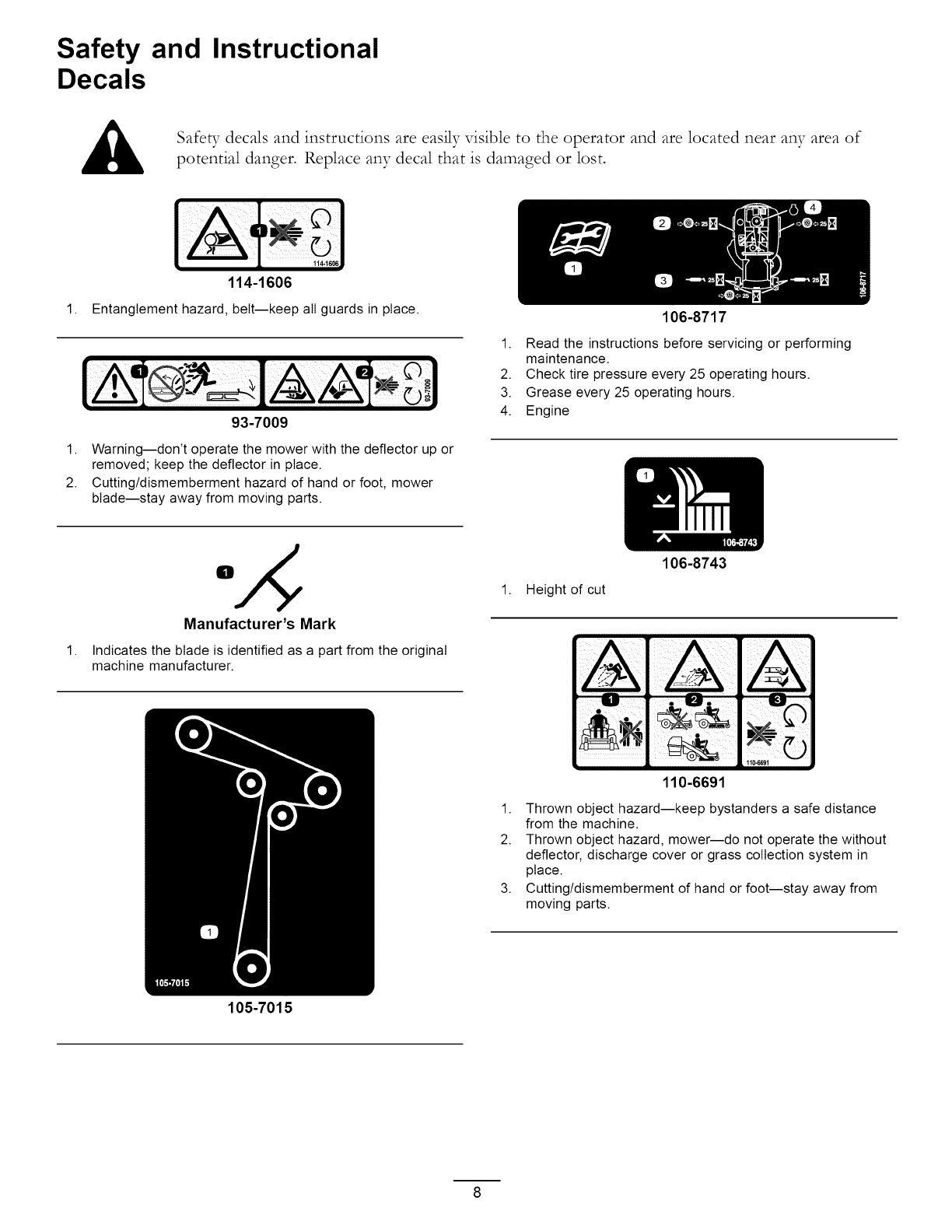
Safety and Instructional
Decals
1.
Safeb7 decals and instructions are easily visible to the operator and are located near any area of
potential danger. Replace any decal that is damaged or lost.
114-1606
Entanglement hazard, belt--keep all guards in place.
93-7009
106-8717
1. Read the instructions before servicing or performing
maintenance.
2. Check tire pressure every 25 operating hours.
3. Grease every 25 operating hours.
4. Engine
1. Warning--don't operate the mower with the deflector up or
removed; keep the deflector in place.
2. Cutting/dismemberment hazard of hand or foot, mower
blade--stay away from moving parts.
1.
Manufacturer's Mark
Indicates the blade is identified as a part from the original
machine manufacturer.
105-7015
1. Height of cut
106-8743
110-6691
1. Thrown object hazard--keep bystanders a safe distance
from the machine.
2. Thrown object hazard, mower--do not operate the without
deflector, discharge cover or grass collection system in
place.
3. Cutting/dismemberment of hand or foot--stay away from
moving parts.
0
0
0
0
0
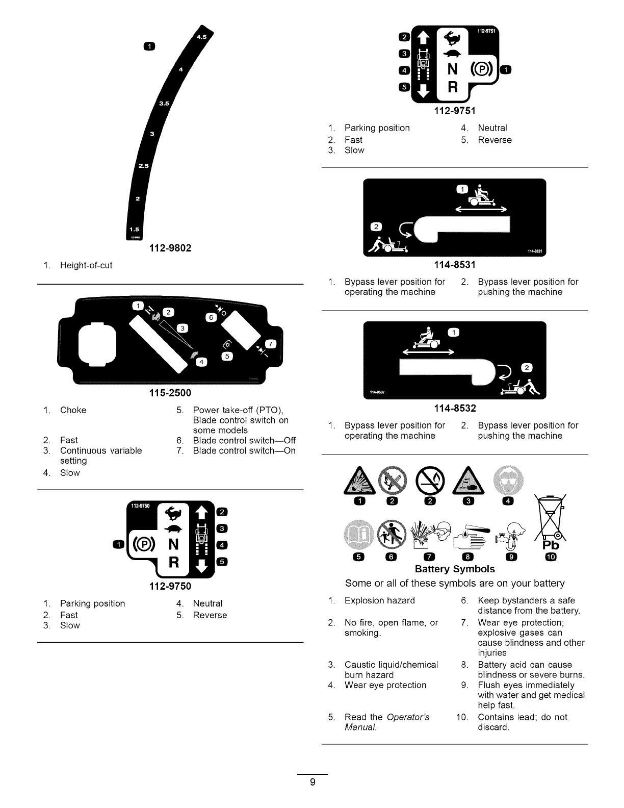
112-9751
1. Parking position 4. Neutral
2. Fast 5. Reverse
3. Stow
1. Height-of-cut
112-9802
115-2500
114-8531
1. Bypass lever position for 2. Bypass lever position for
operating the machine pushing the machine
1. Choke
2. Fast
3. Continuous variable
setting
4. Stow
5. Power take-off (PTO),
Blade control switch on
some models
6. Blade control switch--Off
7. Blade control switch--On
Ell
1. Parking position
2. Fast
3. Stow
N
0
0
0
0
112-9750
4. Neutral
5. Reverse
1.
114-8532
Bypass lever position for 2. Bypass lever position for
operating the machine pushing the machine
0 0 0 0 0
0 0 0 0 0
Battery Symbols
Some or all of these symbols are on your battery
Q
1. Explosion hazard 6. Keep bystanders a safe
distance from the battery.
2. No fire, open flame, or 7. Wear eye protection;
smoking, explosive gases can
cause blindness and other
injuries
3. Caustic liquid/chemical 8. Battery acid can cause
burn hazard blindness or severe burns.
4. Wear eye protection 9. Flush eyes immediately
with water and get medical
help fast.
5. Read the Operator's 10. Contains lead; do not
Manual. discard.
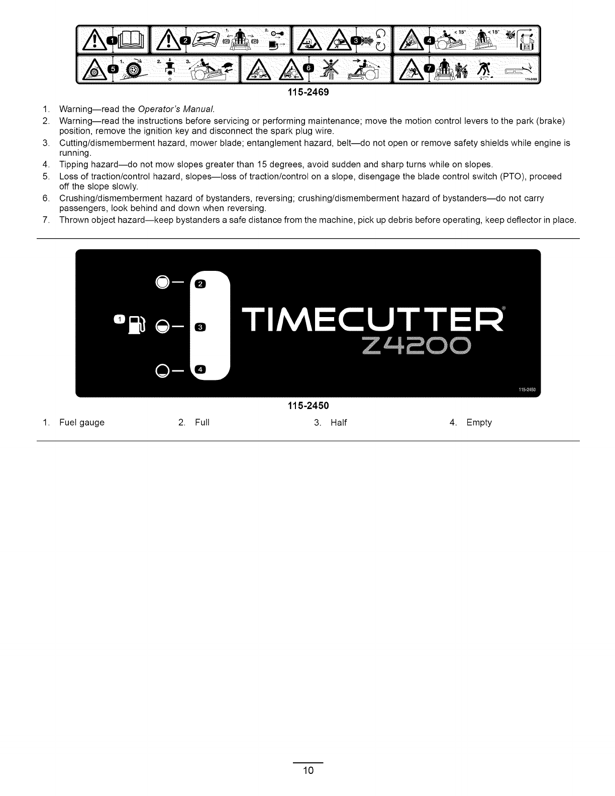
115-2469
1. Warning--read the Operator's Manual
2. Warning--read the instructions before servicing or performing maintenance; move the motion control levers to the park (brake)
position, remove the ignition key and disconnect the spark plug wire.
3. Cutting/dismemberment hazard, mower blade; entanglement hazard, belt--do not open or remove safety shields while engine is
running.
4. Tipping hazard--do not mow slopes greater than 15 degrees, avoid sudden and sharp turns while on slopes.
5. Loss of traction/controI hazard, slopes--loss of traction/controI on a slope, disengage the blade control switch (PTO), proceed
off the slope slowly.
6. Crushing/dismemberment hazard of bystanders, reversing; crushing/dismemberment hazard of bystanders--do not carry
passengers, look behind and down when reversing.
7. Thrown object hazard--keep bystanders a safe distance from the machine, pick up debris before operating, keep deflector in place.
115-2450
1. Fuel gauge 2. Full 3. Half 4. Empty
10
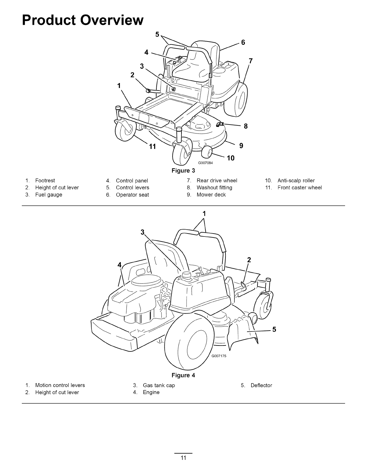
Product Overview
4
3
2
7
8
1. Footrest
2. Height of cut lever
3. Fuel gauge
9
4.
5.
6.
Figure 3
Control panel 7.
Control levers 8.
Operator seat 9.
10
G007084
Rear drive wheel
Washout fitting
Mower deck
10. Anti-scalp roller
11. Front caster wheel
42
7175
1. Motion control levers
2. Height of cut lever
Figure 4
3. Gas tank cap
4. Engine
5. Deflector
11
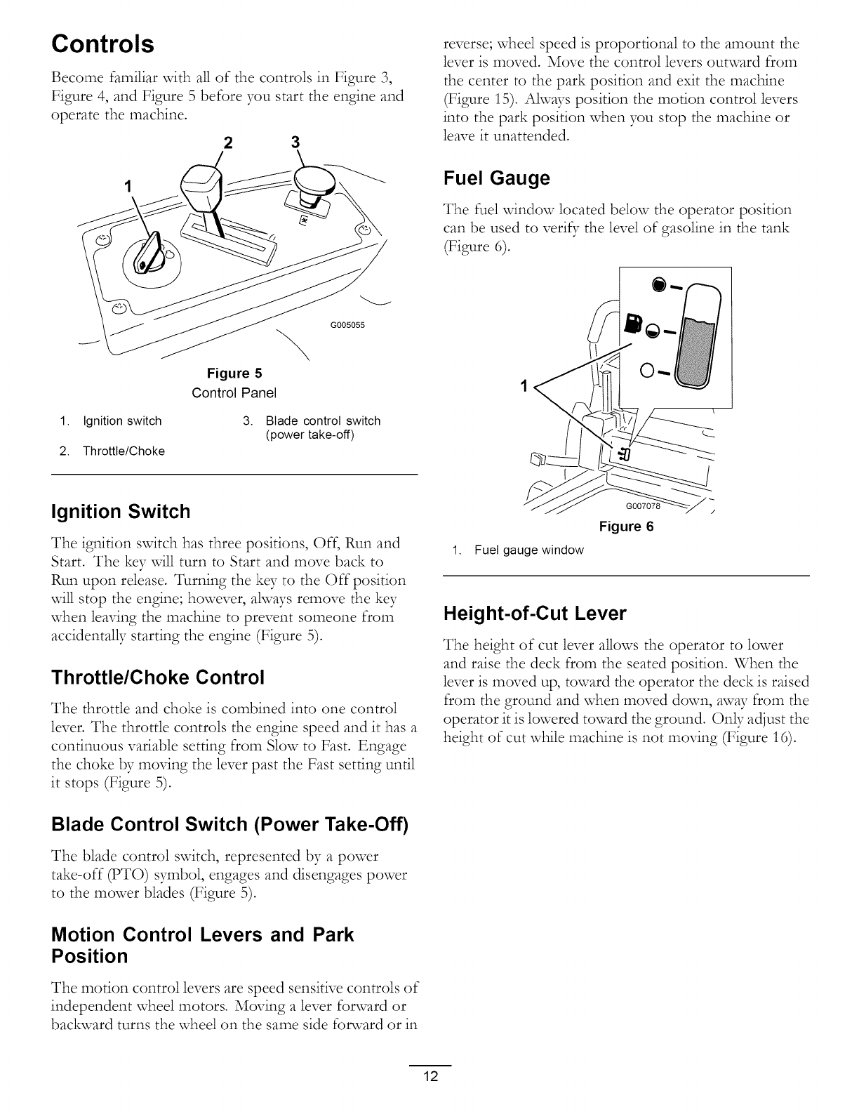
Controls
Become familiar vdth all of the controls in Figure 3,
Figure 4, and Figure 5 before you start the engine and
operate the machine.
2 3
G005055
Figure 5
Control Panel
1. Ignition switch 3. Blade control switch
(power take-off)
2. Throttle/Choke
Ignition Switch
The ignition switch has three positions, Off, Run and
Start. The key will turn to Start and move back to
Run upon release. Turning the key to the Off position
will stop the engine; however, always remove the key
when leaving the machine to prevent someone from
accidentally starting the engine (Figure 5).
Throttle/Choke Control
The throttle and choke is combined into one control
lever. The throttle controls the engine speed and it has a
continuous variable setting from Slow to Fast. Engage
the choke by moving the lever past the Fast setting until
it stops (Figure 5).
Blade Control Switch (Power Take-Off)
The blade control switch, represented by a power
take-off (PTO) symbol, engages and disengages power
to the mower blades (Figure 5).
Motion Control Levers and Park
Position
The motion control levers are speed sensitive controls of
independent wheel motors. Moving a lever forward or
backward turns the wheel on the same side fonvard or in
reverse; wheel speed is proportional to the amount the
lever is moved. Move the control levers outward from
the center to the park position and exit the machine
(Figure 15). Always position the motion control levers
into the park position when you stop the machine or
leave it unattended.
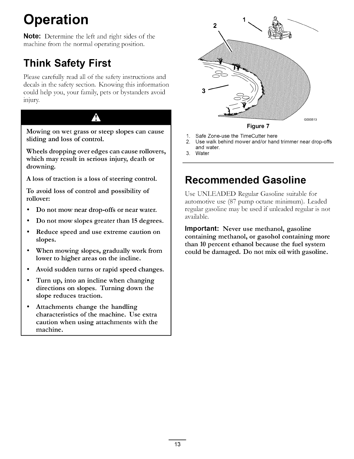
Fuel Gauge
The fuel vdndow located below the operator position
can be used to veri_; the level of gasoline in the tank
(Figure 6).
1. Fuel gauge window
G007078
Figure 6
Height-of-Cut Lever
The height of cut lever allows the operator to lower
and raise the deck from the seated position. When the
lever is moved up, toward the operator the deck is raised
from the ground and when moved down, away from the
operator it is lowered toward the ground. Only adjust the
height of cut while machine is not moving (Figure 16).
12
Operation
Note: Determine the left and right sides of the
machine from the normal operating position.
2\
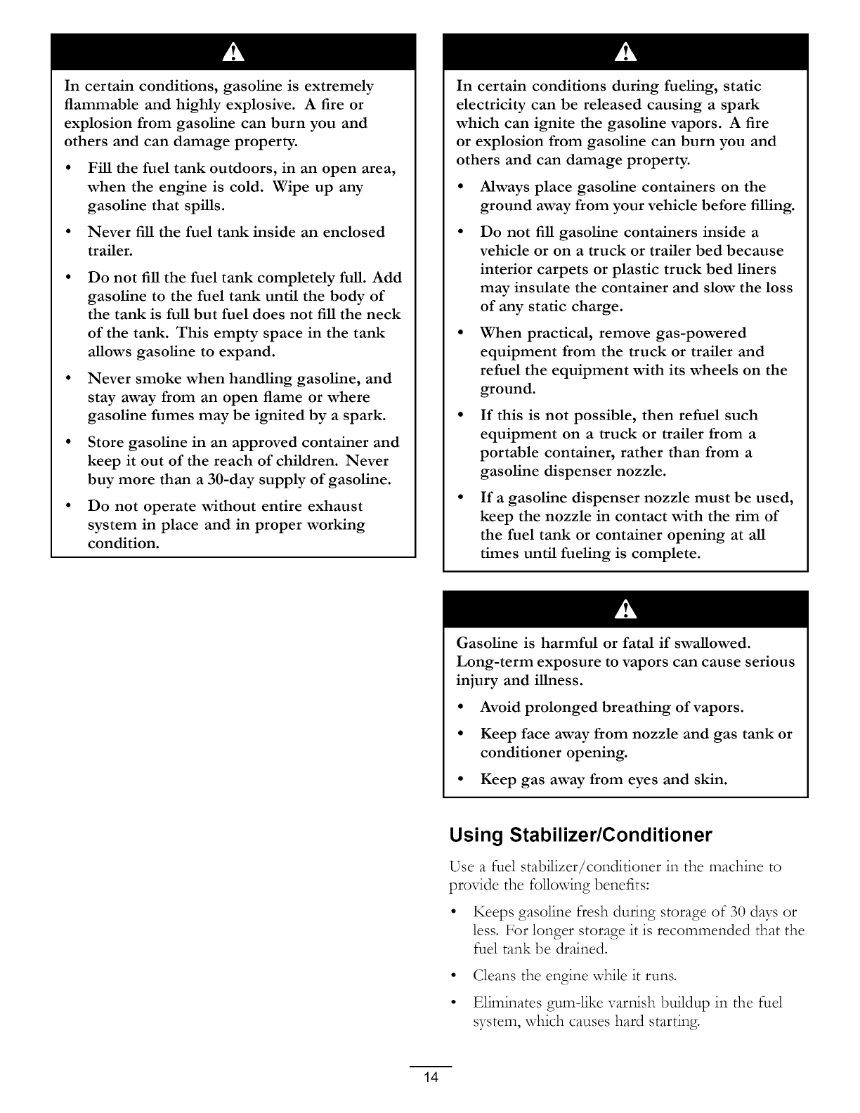
Think Safety First
Please carefully read all of the safe b- instructions and
decals in the safe b- section. Knowing this information
could help you, your famil3; pets or bystanders avoid
injur3=
Mowing on wet grass or steep slopes can cause
sliding and loss of control.
Wheels dropping over edges can cause rollovers,
which may result in serious injury, death or
drowning.
A loss of traction is a loss of steering control.
To avoid loss of control and possibility of
rollover:
• Do not mow near drop-offs or near water.
• Do not mow slopes greater than 15 degrees.
• Reduce speed and use extreme caution on
slopes.
• When mowing slopes, gradually work from
lower to higher areas on the incline.
• Avoid sudden turns or rapid speed changes.
• Turn up, into an incline when changing
directions on slopes. Turning down the
slope reduces traction.
• Attachments change the handling
characteristics of the machine. Use extra
caution when using attachments with the
machine.
G0005t3
Figure 7
1. Safe Zone-use the TimeCutter here
2. Use walk behind mower and/or hand trimmer near drop-offs
and water.
3. Water
Recommended Gasoline
Use UNLEADED Regular Gasoline suitable for
automotive use (87 pump octane minimum). Leaded
regular gasoline may be used if unleaded regular is not
available.
Important: Never use methanol, gasoline
containing methanol, or gasohol containing more
than 10 percent ethanol because the fuel system
could be damaged. Do not mix oil with gasoline.
13
In certain conditions, gasoline is extremely
flammable and highly explosive. A fire or
explosion from gasoline can burn you and
others and can damage property.
Fill the fuel tank outdoors, in an open area,
when the engine is cold. Wipe up any
gasoline that spills.
Never fill the fuel tank inside an enclosed
trailer.
Do not fill the fuel tank completely full. Add
gasoline to the fuel tank until the body of
the tank is full but fuel does not fill the neck
of the tank. This empty space in the tank
allows gasoline to expand.
Never smoke when handling gasoline, and
stay away from an open flame or where
gasoline fumes may be ignited by a spark.
Store gasoline in an approved container and
keep it out of the reach of children. Never
buy more than a 30-day supply of gasoline.
Do not operate without entire exhaust
system in place and in proper working
condition.
In certain conditions during fueling, static
electricity can be released causing a spark
which can ignite the gasoline vapors. A fire
or explosion from gasoline can burn you and
others and can damage property.
• Always place gasoline containers on the
ground away from your vehicle before filling.
Do not fill gasoline containers inside a
vehicle or on a truck or trailer bed because
interior carpets or plastic truck bed liners
may insulate the container and slow the loss
of any static charge.
When practical, remove gas-powered
equipment from the truck or trailer and
refuel the equipment with its wheels on the
ground.
If this is not possible, then refuel such
equipment on a truck or trailer from a
portable container, rather than from a
gasoline dispenser nozzle.
If a gasoline dispenser nozzle must be used,
keep the nozzle in contact with the rim of
the fuel tank or container opening at all
times until fueling is complete.
Gasoline is harmful or fatal if swallowed.
Long-term exposure to vapors can cause serious
injury and illness.
• Avoid prolonged breathing of vapors.
• Keep face away from nozzle and gas tank or
conditioner opening.
• Keep gas away from eyes and skin.
Using Stabilizer/Conditioner
Use a fuel stabilizer/conditioner in the machine to
provide the following benefits:
• Keeps gasoline flesh during storage of 30 days or
less. For longer storage it is recommended that the
fuel tank be drained.
° Cleans the engine while it runs.
• Eliminates gum-like varnish buildup in the fuel
system, which causes hard starting.
14
Add the correct amount of gas stabilizer/conditioner
to the gas.
Note: A fuel stabilizer/conditioner is most effective
when mixed with fresh gasoline. To mitcimize the
chance of varnish deposits in the fuel system, use fuel
stabilizer at all times.
Gasoline/Alcohol blends
Gasohol (up to 10 percent ethyl alcohol, 90 percent
unleaded gasoline by volume) is approved for fuel use
by the engine manufacturer. Other gasoline/alcohol
blends, such as E85, are not approved.
Gasoline/Ether blends
Methyl Tertiary Butyl Ether (MTBE) and unleaded
gasoline blends (up to a maximum of 15 percent MTBE
by volume) are approved for fuel use by the engine
manufacturer. Other gasoline/ether blends are not
approved.
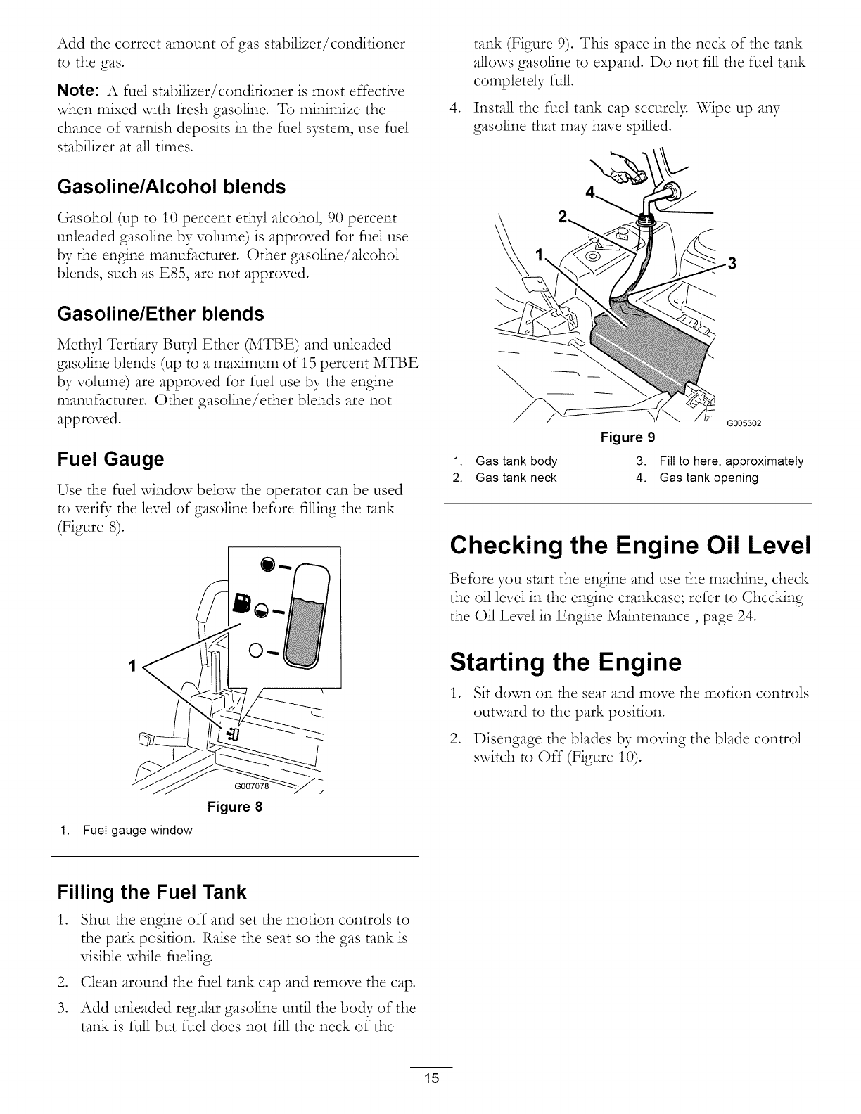
Fuel Gauge
Use the fuel window below the operator can be used
to veri_7 the level of gasoline before filling the tank
(Figure 8).
Figure 8
1. Fuel gauge window
,
tank (Figure 9). This space in the neck of the tank
allows gasoline to expand. Do not fill the fuel tank
completely full.
Install the fuel tank cap securel> Wipe up any
gasoline that may have spilled.
\
Figure 9
1. Gas tank body 3.
2. Gas tank neck 4.
G005302
Fill to here, approximately
Gas tank opening
Checking the Engine Oil Level
Before you start the engine and use the machine, check
the oil level in the engine crankcase; refer to Chec_ng
the Oil Level in Engine Maintenance, page 24.
Starting the Engine
1. Sit down on the seat and move the motion controls
outward to the park position.
2. Disengage the blades by moving the blade control
switch to Off (Figure 10).
Filling the Fuel Tank
1. Shut the engine off and set the motion controls to
the park position. Raise the seat so the gas tank is
visible while fueling.
2. Clean around the fuel tank cap and remove the cap.
3. Add unleaded regular gasoline until the body of the
tank is full but fuel does not fill the neck of the
15
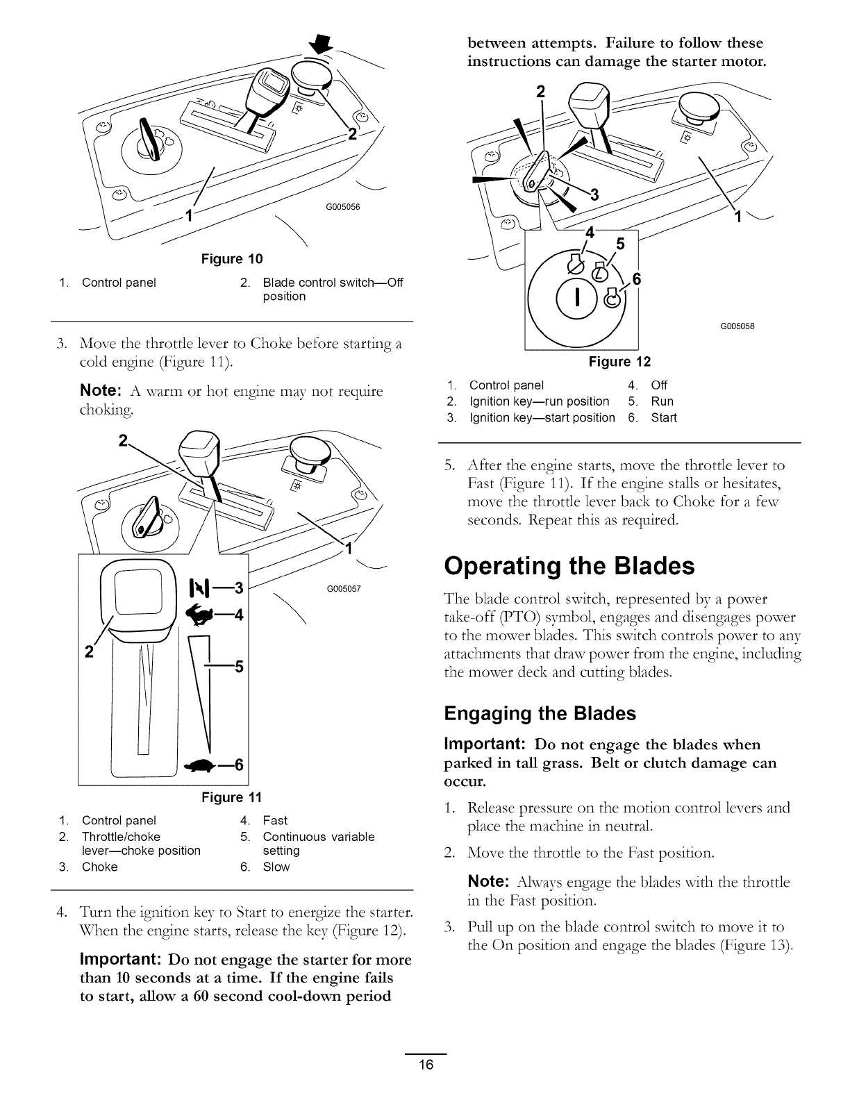
1.
,
Control panel
G005056
Figure 10
2. Blade control switch--Off
position
Move the throttle lever to Choke before starting a
cold engine (Figure 11).
Note: A warm or hot engine may not require
choMng.
between attempts. Failure to follow these
instructions can damage the starter motor.
2
G005058
Figure 12
1. Control panel 4. Off
2. Ignition key--run position 5. Run
3. Ignition key--start position 6. Start
After the engine starts, move the throttle lever to
Fast (Figure 11). If the engine stalls or hesitates,
move the throttle lever back to Choke for a few
seconds. Repeat this as required•
.gilpin6
J
G005057
Figure 11
1. Control panel 4. Fast
2. Throttle/choke 5. Continuous variable
lever--choke position setting
3. Choke 6. Stow
,Turn the ignition key to Start to energize the starter•
When the engine starts, release the key (Figure 12).
Important: Do not engage the starter for more
than 10 seconds at a time. If the engine fails
to start, allow a 60 second cool-down period
Operating the Blades
The blade control switch, represented by a power
take-off (PTO) symbol, engages and disengages power
to the mower blades• This switch controls power to aW
attachments that draw power from the engine, including
the mower deck and cutting blades•
Engaging the Blades
Important: Do not engage the blades when
parked in tall grass. Belt or clutch damage can
occur.
,Release pressure on the motion control levers and
place the machine in neutral.
2. Move the throttle to the Fast position.
,
Note: Always engage the blades with the throttle
in the Fast position.
Pull up on the blade control switch to move it to
the On position and engage the blades (Figure 13).
16
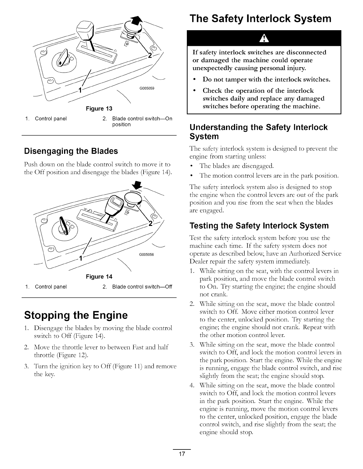
Figure 13
1. Control panel 2.
G005059
Blade control switch--On
position
Disengaging the Blades
Push down on the blade control switch to move it to
the Off position and disengage the blades (Figure 14).
1. Control panel
G005056
Figure 14
2. [3lade control switch--OF
Stopping the Engine
1. Disengage the blades by moving the blade control
switch to Off (Figure 14).
2. Move the throttle lever to between Fast and half
throttle (Figure 12).
3. Turn the igaition key to Off (Figure 11) and remove
the ke?:
The Safety Interlock System
If safety interlock switches are disconnected
or damaged the machine could operate
unexpectedly causing personal injury.
•Do not tamper with the interlock switches.
• Check the operation of the interlock
switches daily and replace any damaged
switches before operating the machine.
Understanding the Safety Interlock
System
The safety interlock system is designed to prevent the
engine from starting unless:
• The blades are disengaged.
• The motion control levers are in the park position.
The safety interlock system also is designed to stop
the engine when the control levers are out of the park
position and you rise from the seat when the blades
are engaged.
Testing the Safety Interlock System
Test the safety interlock system before you use the
machine each time. If the safety system does not
operate as described belov_, have an Authorized Service
Dealer repair the safety system immediatel?:
1. While sitting on the seat, with the control levers in
park position, and move the blade control switch
to On. Try starting the engine; the engine should
not crank.
.While sitting on the seat, move the blade control
switch to Off. Move either motion control lever
to the center, unlocked position. Try starting the
engine; the engine should not crank. Repeat with
the other motion control lever.
.
.
While sitting on the seat, move the blade control
switch to Off, and lock the motion control levers in
the park position. Start the engine. While the engine
is runaing, engage the blade control switch, and rise
slightly from the seat; the engine should stop.
While sitting on the seat, move the blade control
switch to Off, and lock the motion control levers
in the park position. Start the engine. While the
engine is runaing, move the motion control levers
to the center, unlocked position, engage the blade
control switch, and rise slightly from the seat; the
engine should stop.
17
Driving Forward or Backward
The throttle control regulates the engine speed as
measured in rpm (revolutions per minute). Place
the throttle control in the Fast position for best
performance. Ahvays operate in the fL_ throttle
position.
To turn, release pressure on the motion control lever
toward the direction you want to turn (Figure 15).
The farther you move the motion control levers in
either direction, the faster the machine will move in
that direction.
To stop, pull the motion control levers to neutral.
The machine can spin very rapidly. The
operator may lose control of the machine
and cause personal injury or damage to the
machine.
• Use caution when making turns.
• Slow the machine down before making
sharp turns.
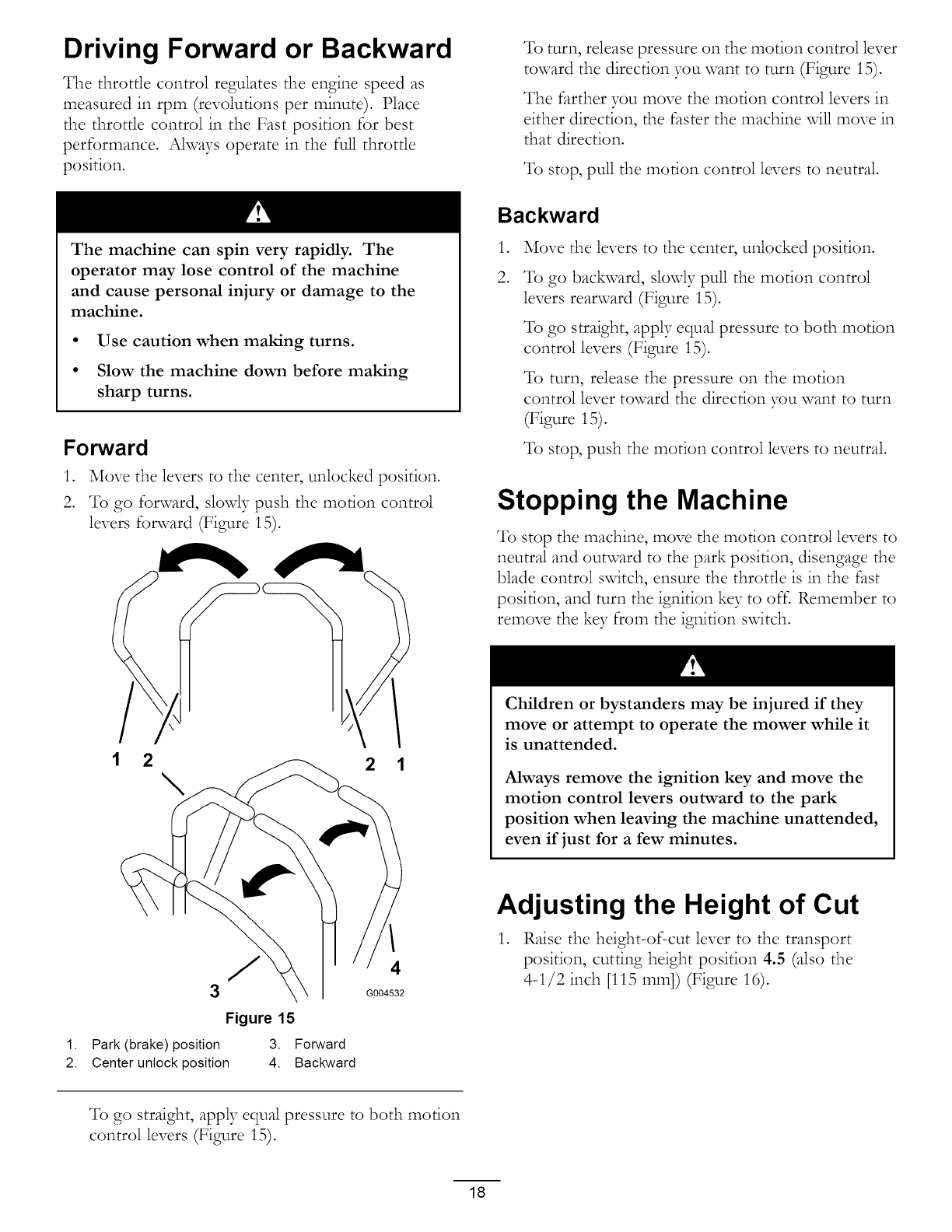
Forward
1. Move the levers to the center, unlocked position.
2. To go forward, slowly push the motion control
levers forward (Figure 15).
1 2 2 1
/
3
Figure 15
1. Park (brake) position 3. Forward
2. Center unlock position 4. Backward
4
G004532
Backward
,
2.
Move the levers to the center, unlocked position.
To go backward, slowly pull the motion control
levers rearward (Figure 15).
To go straight, apply equal pressure to both motion
control levers (Figure 15).
To turn, release the pressure on the motion
control lever toward the direction you want to turn
(Figure 15).
To stop, push the motion control levers to neutral.
Stopping the Machine
To stop the machine, move the motion control levers to
neutral and outward to the park position, disengage the
blade control switch, ensure the throttle is in the fast
position, and turn the ignition key to off. Remember to
remove the key from the ignition switch.
Children or bystanders may be injured if they
move or attempt to operate the mower while it
is unattended.
Always remove the ignition key and move the
motion control levers outward to the park
position when leaving the machine unattended,
even if just for a few minutes.
Adjusting the Height of Cut
1. Raise the height-of-cut lever to the transport
position, cutting height position 4.5 (also the
4-1/2 inch [115 mm]) (Figure 16).
To go straight, apply equal pressure to both motion
control levers (Figure 15).
18
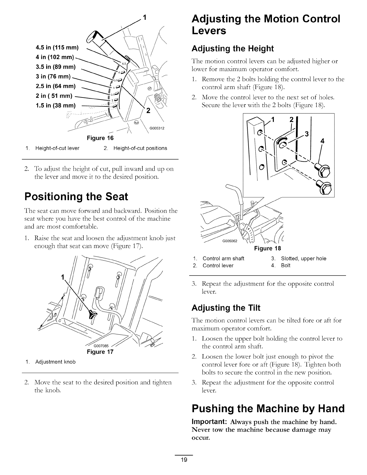
4.5 in (115 mm)
4 in (102 mm)
3.5 in (89 mm)
3 in (76 mm)
2.5 in (64 mm)
2 in ( 51 mm)
1.5 in (38 mm)
;7,:...... '-...........
1. Height-of-cut lever
G005312
Figure 16
2. Height-of-cut positions
2. To adjust the height of cut, pull inward and up on
the lever and move it to the desired position.
Positioning the Seat
The seat can move forward and backward. Position the
seat where you have the best control of the machine
and are most comfortable.
1. Raise the seat and loosen the adjustment M_ob just
enough that seat can move (Figure 17).
1. Adjustment knob
Figure 17
2. Move the seat to the desired position and tighten
the kmob.
Adjusting the Motion Control
Levers
Adjusting the Height
The motion control levers can be adjusted higher or
lower for maximum operator comfort.
1. Remove the 2 bolts holding the control lever to the
control arm shaft (Figure 18).
2. Move the control lever to the next set of holes.
Secure the lever with the 2 bolts (Figure 18).
2
G005062
Figure 18
1. Control arm shaft 3. Slotted, upper hole
2. Control lever 4. Bolt
3. Repeat the adjustment for the opposite control
lever.
Adjusting the Tilt
The motion control levers can be tilted fore or aft for
maximum operator comfort.
1. Loosen the upper bolt holding the control lever to
the control arm shaft.
2. Loosen the lower bolt just enough to pivot the
control lever fore or aft (Figure 18). Tighten both
bolts to secure the control in the new position.
3. Repeat the adjustment for the opposite control
lever.
Pushing the Machine by Hand
Important: Always push the machine by hand.
Never tow the machine because damage may
occur.
19
To Push the Machine
1. Park the machine on a level surface and disengage
the blade control svdtch.
,
,
,
Move the motion control levers outward to park
position, stop the engine, remove the ke5 and wait
for all moving parts to stop before leaving the
operating position.
Locate the bypass levers at the rear of the machine,
on the left and right side of the frame.
Move the bypass levers reanvard and then down
to lock them in place as shown in Figure 19 to
disengage the wheel motors. Repeat this on each
side of the machine.
5. Move the motion control levers inward to the
neutral position.
The machine is now able to be pushed t937hand.
G007086
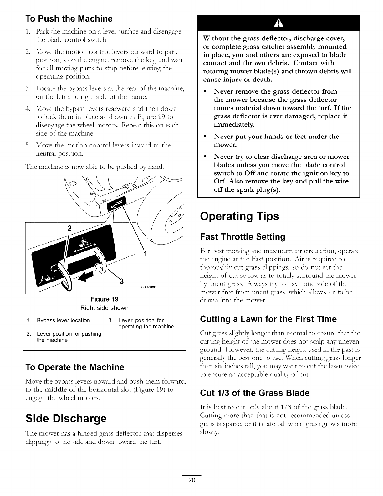
Figure 19
Right side shown
1. Bypass lever location
2. Lever position for pushing
the machine
3. Lever position for
operating the machine
To Operate the Machine
Move the bypass levers upward and push them forward,
to the middle of the horizontal slot (Figure 19) to
engage the wheel motors.
Side Discharge
The mower has a hinged grass deflector that disperses
clippings to the side and down toward the turf.
Without the grass deflector, discharge cover,
or complete grass catcher assembly mounted
in place, you and others are exposed to blade
contact and thrown debris. Contact with
rotating mower blade(s) and thrown debris will
cause injury or death.
Never remove the grass deflector from
the mower because the grass deflector
routes material down toward the turf. If the
grass deflector is ever damaged, replace it
immediately.
Never put your hands or feet under the
mower.
Never try to clear discharge area or mower
blades unless you move the blade control
switch to Off and rotate the ignition key to
Off. Also remove the key and pull the wire
off the spark plug(s).
Operating Tips
Fast Throttle Setting
For best movdng and maximum air circulation, operate
the engine at the Fast position. Air is required to
thoroughly cut grass clippings, so do not set the
height-of-cut so low as to totally surround the mower
by uncut grass. Always try to have one side of the
mower free from uncut grass, which allows air to be
drawn into the mower.
Cutting a Lawn for the First Time
Cut grass slightly longer than normal to ensure that the
cutting height of the mower does not scalp any uneven
ground. However, the cutting height used in the past is
generally the best one to use. When cutting grass longer
than six inches tall, you may want to cut the lawn twice
to ensure an acceptable quality of cut.
Cut 1/3 of the Grass Blade
It is best to cut only about 1/3 of the grass blade.
Cutting more than that is not recommended unless
grass is sparse, or it is late fall when grass grows more
slowly.
20

Mowing Direction
Alternate mowing direction to keep the grass standing
straight. This also helps disperse clippings which
enhances decomposition and fertilization.
Mow at Correct Intervals
Normal13, mow every four days. But remember,
grass grows at different rates at different times. So
to maintain the same cutting height, which is a good
practice, mow more often in early spring. As the grass
growth rate slows in mid summer, mow less frequently.
If you cannot mow for an extended period, first mow
at a high cutting height; then mow again two days later
at a lower height setting.
Cutting Speed
To improve cut quali U. use a slower ground speed.
Avoid Cutting Too Low
If the cutting width of the mower is wider than the
mower you previously used, raise the cutting height to
ensure that uneven turf is not cut too short.
grass brown at the edges, which slows growth and
increases the chance of disease. Check the cutter blades
daily for sharpness, and for aW wear or damage. File
down aW nicks and sharpen the blades as necessar> If
a blade is damaged or worn, replace it immediately with
a genuine Toro replacement blade.
Long Grass
If the grass is ever allowed to grow slightly longer than
normal, or if it contains a high degree of moisture, raise
the cutting height higher than usual and cut the grass at
this setting. Then cut the grass again using the lower,
normal setting.
When Stopping
If the machine's forward motion must be stopped while
mowing, a clump of grass clippings may drop onto your
lawn. To avoid this, move onto a previously cut area
with the blades engaged.
Keep the Underside of the Mower
Clean
Clean clippings and dirt from the underside of the
mower after each use. If grass and dirt build up inside
the mower, cutting quality will eventually become
unsatisfactor>
Blade Maintenance
Maintain a sharp blade throughout the cutting season
because a sharp blade cuts cleanly without tearing or
shredding the grass blades. Tearing and shredding turns
21
Maintenance
Note: Determine the left and right sides of the m;_chine from the norm;_l operating position.
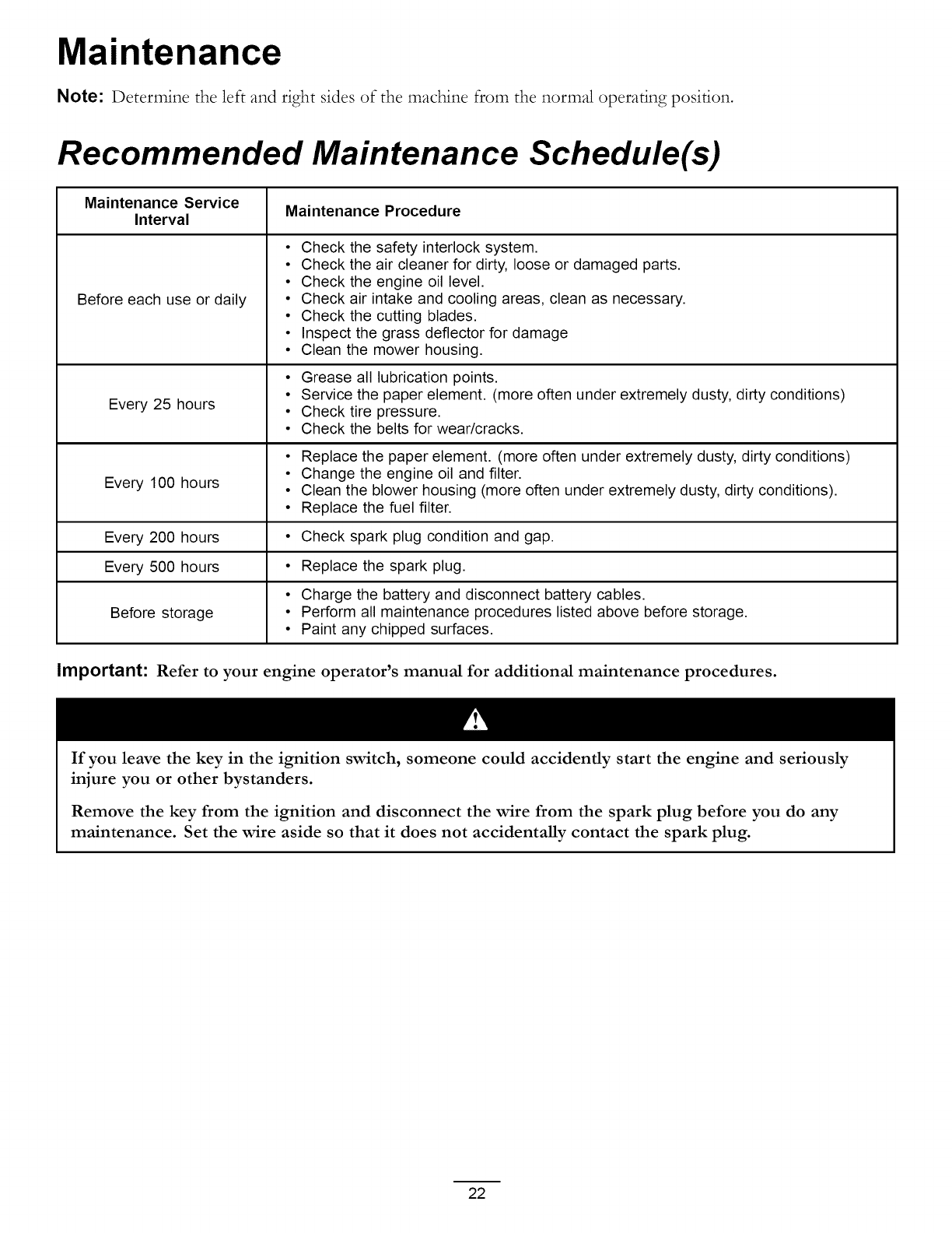
Recommended Maintenance Schedule(s)
Maintenance Service Maintenance Procedure
Interval
Before each use or daily
•Check the safety interlock system.
• Check the air cleaner for dirty, loose or damaged parts.
• Check the engine oil level.
• Check air intake and cooling areas, clean as necessary.
• Check the cutting blades.
• Inspect the grass deflector for damage
• Clean the mower housing.
• Grease all lubrication points.
• Service the paper element. (more often under extremely dusty, dirty conditions)
Every 25 hours • Check tire pressure.
• Check the belts for wear/cracks.
• Replace the paper element. (more often under extremely dusty, dirty conditions)
• Change the engine oil and filter.
Every 100 hours • Clean the blower housing (more often under extremely dusty, dirty conditions).
• Replace the fuel filter.
Every 200 hours • Check spark plug condition and gap.
Every 500 hours • Replace the spark plug.
• Charge the battery and disconnect battery cables.
Before storage • Perform all maintenance procedures listed above before storage.
• Paint any chipped surfaces.
Important: Refer to your engine operator's manual for additional maintenance procedures.
If you leave the key in the ignition switch, someone could accidently start the engine and seriously
injure you or other bystanders.
Remove the key from the ignition and disconnect the wire from the spark plug before you do any
maintenance. Set the wire aside so that it does not accidentally contact the spark plug.
22
Premaintenance
Procedures
Raising the Seat
Make sure the motion control levers are locked in the
park position. Lift the seat forward and lower it to the
floor board.
The following components can be accessed by raising
the seat:
• Serial plate
• Service decal
• Seat adjustment M_ob
•Fuel filter
• Fuses
• Battery cables
Lubrication
Greasing the Bearings
Service Interval: Every 25 hours--Grease all
lubrication points.
Grease Type: No. 2 General Purpose Lithium Base
Grease
1. Park the machine on a level surface and disengage
the blade control switch.
,
,
Move the motion control levers outward to the
park position, stop the engine, remove the key and
wait for all moving parts to stop before leaving the
operating position.
Clean the grease fittings (Figure 21 and Figure 22)
with a rag. Make sure to scrape any paint off of the
front of the fitting(s).
Accessing the Battery
1. Raise the seat.
2. Remove the TORX :R:'head fasteners (T25) securing
the left cover to the frame as shown in Figure 20.
2
\
\
1.
2.
2
.//_ G00506!
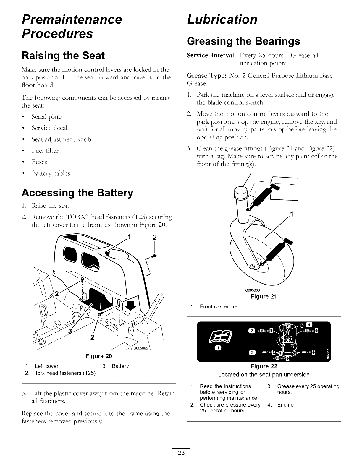
Figure 20
Left cover 3. Battery
Torx head fasteners (T25)
3. Lift the plastic cover away from the machine. Retain
all fasteners.
Replace the cover and secure it to the frame using the
fasteners removed previousl):
1. Front caster tire
J 1
G005066
Figure 21
Figure 22
Located on the seat pan underside
1. Read the instructions
before servicing or
performing maintenance.
2. Check tire pressure every
25 operating hours.
3. Grease every 25 operating
hours.
4. Engine
23
,Connect a grease gun to each fitting (Figure 21 and
Figure 22). Pump grease into the fittings until grease
begins to ooze out of the bearings.
5. Wipe up any excess grease.
Engine Maintenance
Servicing the Air Cleaner
Service Interval: Before each use or dail3_Check the
air cleaner for dirb, loose or damaged
parts.
This engine is equipped with a replaceable, high density
paper air cleaner element. Check the air cleaner daily or
before starting the engine. Check for a buildup of dirt
and debris around the air cleaner system. Keep this area
dean. Also check for loose or damaged components.
Replace all bent or damaged air cleaner components.
Note: Operating the engine with loose or damaged air
cleaner components could allow unfiltered air into the
engine causing premature wear and failure.
Note: Service the air cleaner more often under
extremely dusb. dirty conditions.
o
G005300 J
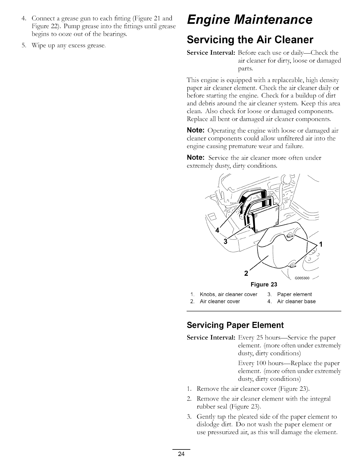
Figure 23
1. Knobs, air cleaner cover 3. Paper element
2. Air cleaner cover 4. Air cleaner base
Servicing Paper Element
Service Interval: Every 25 hours--Service the paper
dement. (more often under extremely
dust B dirty conditions)
Every 100 hours--Replace the paper
dement. (more often under extremely
dust B dirty conditions)
1. Remove the air cleaner cover (Figure 23).
2. Remove the air cleaner element with the integral
rubber seal (Figure 23).
3. Gently tap the pleated side of the paper element to
dislodge dirt. Do not wash the paper dement or
use pressurized air, as this will damage the element.
24
,
,
Replace a dirt), bent, or damaged element. Handle
new elements carefully; do not use if the rubber seal
is damaged.
Clean all air cleaner components of any accumulated
dirt or foreign material. Prevent any dirt from
entering the carburetor.
Install the air cleaner element with the pleated side
"out" and seat the rubber seal onto the edges of the
air cleaner base (Figure 23).
Reinstall the air cleaner cover and secure with the
two M_obs (Figure 23)•
Servicing the Engine Oil
Oil Type: Detergent oil (API service SG, SH, SJ, or
higher)
Crankcase Capacity: 1.6 qt (1.5 1)when the filter is
changed
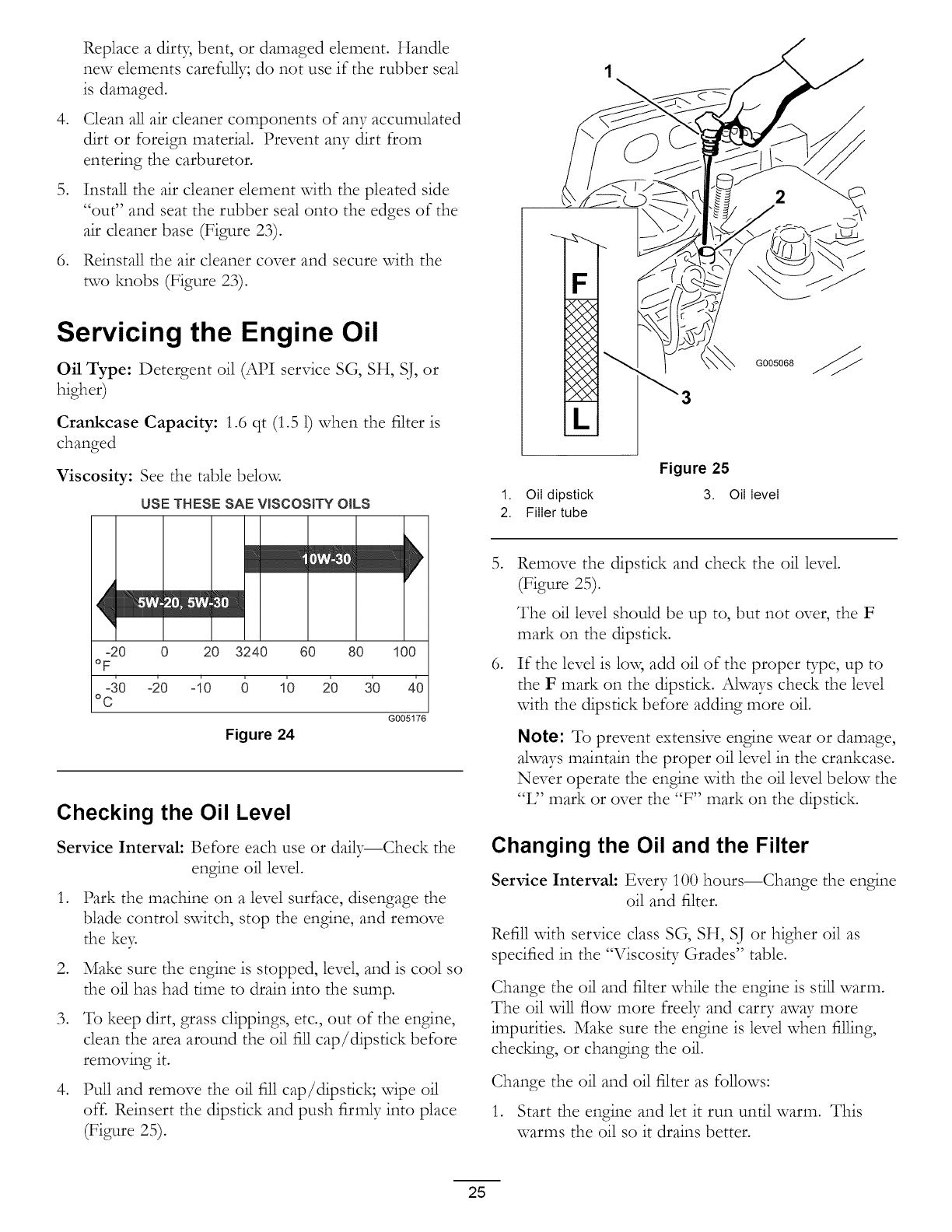
Viscosity: See the table below
USE THESE SAE VISCOSITY OILS
-20 0 20 3240 60 80 100
oF
40 -20 -40 6 10 20 30 40
°C
G005176
Figure 24
Checking the Oil Level
Service Interval: Before each use or daily--Check the
engine oil level.
,
,
,
,
Park the machine on a level surface, disengage the
blade control switch, stop the engine, and remove
the ke)_
Make sure the engine is stopped, level, and is cool so
the oil has had time to drain into the sump.
To keep dirt, grass clippings, etc., out of the engine,
clean the area around the oil fill cap/dipstick before
removing it.
Pull and remove the oil fill cap/dipstick; wipe oil
off. Reinsert the dipstick and push firmly into place
(Figure 25).
L
G005068
1. Oil dipstick
2. Filler tube
Figure 25
3. Oil level
,
Remove the dipstick and check the oil level.
(Figure 25).
The oil level should be up to, but not over, the F
mark on the dipstick.
If the level is lo\_ add oil of the proper type, up to
the F mark on the dipstick• Ahvays check the level
with the dipstick before adding more oil.
Note: To prevent extensive engine wear or damage,
ahvays maintain the proper oil level in the crankcase.
Never operate the engine with the oil level below the
"L" mark or over the "F" mark on the dipstick•
Changing the Oil and the Filter
Service Interval: Every 100 hours--Change the engine
oil and filter•
Refill with service class SG, SH, SJ or higher oil as
\ lscoslty Grades" table.specified in the "T" "
Change the oil and filter while the engine is still warm.
The oil will flow more freely and carry away more
impurities• Make sure the engine is level when filling,
chec_ng, or changing the oil.
Change the oil and oil filter as follows:
1. Start the engine and let it run until warm. This
warms the oil so it drains better.
25

,
,
,
Park the machine so that the drain side is slightly
lower than the opposite side to assure the oil drains
completel>
,
,
Disengage the blade control switch and move the
motion controls outward to the park position.
Stop the engine, remove the ke), and wait for all
moving parts to stop before leaving the operating
position.
Clean the area around the drain vak_e and on the
machine frame. Locate the oil drain hose and slide
it over the drain vahTe (Figure 26)•
24
3
G007093
Figure 26
3.
4.
1. Oil drain hose Hole in frame
2. Drain valve Oil filter
Place the opposite end of the oil drain hose through
the drain hole in the frame (Figure 26).
Place a pan underneath machine directly below the
drain hole in the frame as shown in Figure 27.
1. Oil drain valve
2. Machine frame
3. Oil drain hose
G007087
Figure 27
4. Pan
5. Oil filter
,
,
10.
11.
12.
13.
14.
Open the oil drain vak_e to allow oil to drain
(Figure 27). Remove the oil fill cap/dipstick
(Figure 25).
Be sure to allow ample time for complete drainage.
Remove the old filter and wipe off the mounting pad
(Figure 27)•
When oil has drained completely close the oil drain
valve. Remove the oil drain hose and wipe up any
excess oil on the frame (Figure 27)•
Note: Dispose of the used oil at a recycling center.
Place the new replacement filter in a shallow pan
with the open end up. Pour new oil of the proper
type, in through the threaded center hole. Stop
pouring when the oil reaches the bottom of the
threads• Allow a minute or two for the oil to be
absorbed by the filter material.
Apply a thin film of clean oil to the rubber gasket on
the new filter.
Install the replacement oil filter to the mounting pad.
Turn the oil filter clockwise until the rubber gasket
contacts the pad, then tighten the filter an additional
2/3 to 1 turn (Figure 28).
26
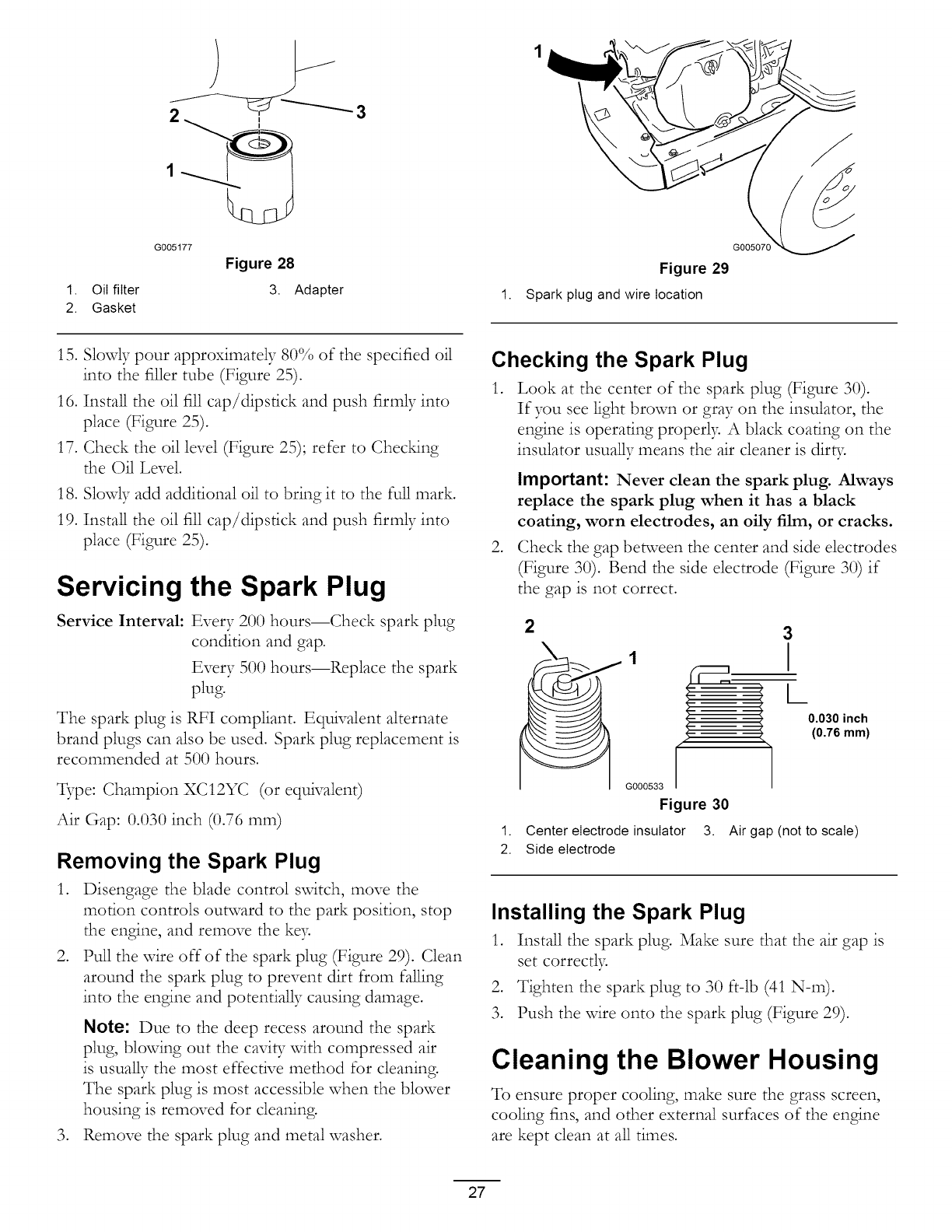
1. Oil filter
2. Gasket
G005177
Figure 28
3. Adapter
Figure 29
1. Spark plug and wire location
G005070
15. Slowly pour approximately 80% of the specified oil
into the filler tube (Figure 25).
16. Install the oil fill cap/dipstick and push firmly into
place (Figure 25).
17. Check the oil level (Figure 25); refer to Chec_ng
the Oil Level.
18. Slowly add additional oil to bring it to the rue mark.
19. Install the oil fill cap/dipstick and push firmly into
place (Figure 25).
Servicing the Spark Plug
Service Interval: Every 200 hours--Check spark plug
condition and gap.
Every 500 hours--Replace the spark
plug.
The spark plug is RFI compliant. Equivalent alternate
brand plugs can also be used. Spark plug replacement is
recommended at 500 hours.
_;pe: Champion XC12YC (or equivalent)
Air Gap: 0.030 inch (0.76 ram)
Removing the Spark Plug
1. Disengage the blade control switch, move the
motion controls outward to the park position, stop
the engine, and remove the ke>
2. Pull the wire off of the spark plug (Figure 29). Clean
around the spark plug to prevent dirt from falling
into the engine and potentially causing damage.
,
Note: Due to the deep recess around the spark
plug, blowing out the caviff with compressed air
is usually the most effective method for cleaning.
The spark plug is most accessible when the blower
housing is removed for clemcing.
Remove the spark plug and metal washer.
Checking the Spark Plug
1. Look at the center of the spark plug (Figure 30).
If you see light brown or gray on the insulator, the
engine is operating properly. A black coating on the
insulator usually means the air cleaner is dirty.
,
Important: Never clean the spark plug. Always
replace the spark plug when it has a black
coating, worn electrodes, an oily film, or cracks.
Check the gap between the center and side electrodes
(Figure 30). Bend the side electrode (Figure 30) if
the gap is not correct.
2
1
G000533
Figure 30
3
I
L
0.030 inch
(0.76 mm)
1. Center electrode insulator 3. Air gap (not to scale)
2. Side electrode
Installing the Spark Plug
1. Install the spark plug. Make sure that the air gap is
set correctly.
2. Tighten the spark plug to 30 ft-lb (41 N-m).
3. Push the vdre onto the spark plug (Figure 29).
Cleaning the Blower Housing
To ensure proper cooling, make sure the grass screen,
cooling fins, and other external surfaces of the engine
are kept clean at all times.
27
Annuallyor every100hoursof operation{moreoften
underextremelydus_%dirty conditions),removethe
blowerhousingandanyothercoolingshrouds.Clean
thecoolingfinsandexternalsurfacesasnecessar):Make
surethecoolingshroudsarereinstalled.Torquethe
blowerhousingscrewsto 5.5ft-lb (7.5N-m).
Important: Operating the engine with a blocked
grass screen, dirty or plugged cooling fins, and/or
cooling shrouds removed, will cause engine damage
due to overheating.
Fuel System
Maintenance
In certain conditions, gasoline is extremely
flammable and highly explosive. A fire or
explosion from gasoline can burn you and
others and can damage property.
•Perform any fuel related maintenance when
the engine is cold. Do this outdoors in an
open area. Wipe up any gasoline that spills.
• Never smoke when draining gasoline, and
stay away from an open flame or where a
spark may ignite the gasoline fumes.
Replacing the Fuel Filter
Service Interval: Every 100 hours--Replace the fuel
filter.
Never install a dir_7 filter if it is removed from the fuel
lille.
,Park the machine oil a level surface and disengage
the blade control svdtch.
2. Move the motion control levers outward to the
park position, stop the engine, remove the keB and
wait for all moving parts to stop before leaving the
operating position.
3. Raise the seat and locate the fuel line coming from
the fuel tank below_ The fuel filter is in the fuel line
between the tank and engine.
28
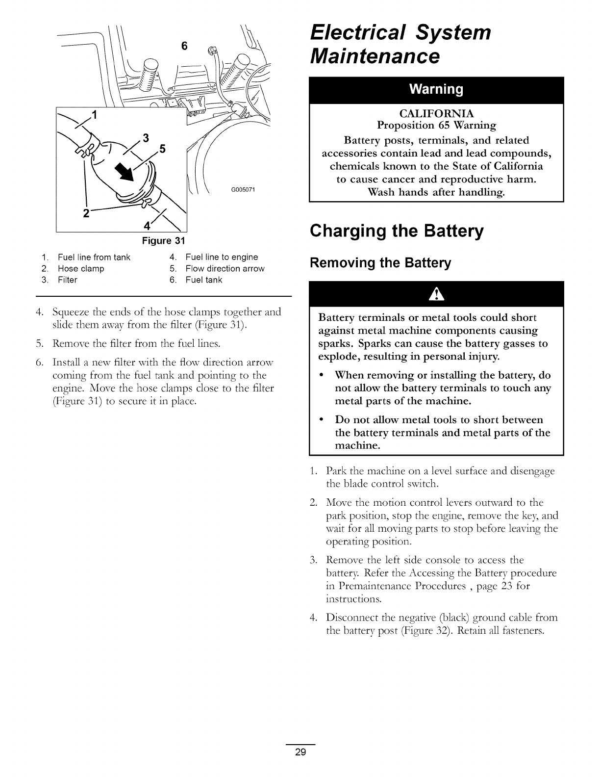
2
6
G005071
Figure 31
1. Fuel line from tank 4. Fuel line to engine
2. Hose clamp 5. Flow direction arrow
3. Filter 6. Fuel tank
Electrical System
Maintenance
CALIFORNIA
Proposition 65 Warning
Battery posts, terminals, and related
accessories contain lead and lead compounds,
chemicals known to the State of California
to cause cancer and reproductive harm.
Wash hands after handling.
Charging the Battery
Removing the Battery
,
6.
Squeeze the ends of the hose clamps together and
slide them away from the filter (Figure 31).
Remove the filter from the fuel lines.
Install a new filter vdth the flow direction arrow
coming from the fuel tank and pointing to the
engine. Move the hose clamps close to the filter
(Figure 31) to secure it in place•
Battery terminals or metal tools could short
against metal machine components causing
sparks. Sparks can cause the battery gasses to
explode, resulting in personal injury.
• When removing or installing the battery, do
not allow the battery terminals to touch any
metal parts of the machine.
• Do not allow metal tools to short between
the battery terminals and metal parts of the
machine.
,
,
,
,
Park the machine on a level surface and disengage
the blade control svdtch.
Move the motion control levers outward to the
park position, stop the engine, remove the key and
wait for aHmoving parts to stop before leaving the
operating position.
Remove the left side console to access the
batter> Refer the Accessing the Battery procedure
in Premaintenance Procedures , page 23 for
instructions.
Disconnect the negative (black) ground cable from
the battery post (Figure 32)• Retain all fasteners.
29

Incorrect battery cable routing could damage
the machine and cables causing sparks. Sparks
can cause the battery gasses to explode,
resulting in personal injury.
• Always disconnect the negative (black)
battery cable before disconnecting the
positive (red) cable.
• Always connect the positive (red) battery
cable before connecting the negative (black)
cable.
5. Slide the rubber cover up the positive (red) cable.
Disconnect the positive (red) cable from the battery
post (Figure 32). Retain all fasteners.
6. Remove the battery hold-down (Figure 32) and lift
the battery from the battery tray.
2 6 5 1
4
G005072 I
Figure 32
1. Battery 5. Negative battery post
2. Positive battery post 6. Wing nut, washer, and bolt
3. Bolt, washer, and nut 7. Battery hold-down
4. Terminal boot
Charging the Battery
Service Interval: Before storage--Charge the battery
and disconnect battery cables.
1. Remove the battery from the chassis; refer to
Removing the Batter 7
2. Charge the battery for a minimum of I hour at 6 to
10 amps. Do not overcharge the batter>
3. When the battery is fully charged, unplug the charger
from the electrical outlet, then disconnect the
charger leads from the battery posts (Figure 33).
4
2
3
1
G000538
Figure 33
1. Positive battery post 3. Red (+) charger lead
2. Negative battery post 4. Black (-) charger lead
Note: Do not run the machine with the battery
disconnected, electrical damage may occur.
Installing the Battery
1. Position the battery in the tray with the terminal
posts toward the operating position (Figure 32).
2. Install the positive (red) battery cable to the positive
(+) battery terminal using the fasteners removed
previously.
3. Install the negative battery cable to the negative
(-) battery terminal using the fasteners removed
previousl)_
4. Slide the red terminal boot onto the positive (red)
battery post.
5. Secure the battery with the hold-down (Figure 32).
6. Install the left side console. Refer to the Accessing
the Battery procedure in Premaintenance Procedures
, page 23 for instructions.
Servicing the Fuses
The electrical system is protected by fuses. It requires
no maintenance; however, if a fuse blows, check the
component/circuit for a malfunction or short.
Fuse:
• Main FI-30 amp, blade-_pe
• Charge Circuit F2-25 amp, blade-type
1. Raise the seat to gain access to the fuse holder
(Figure 34).
2. To replace a fuse, pull out on the fuse to remove it
(Figure 34).
30
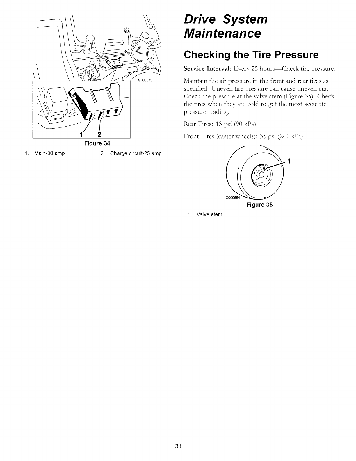
1.
G005073
Main-30 amp
2
Figure 34
2. Charge circuit-25 amp
Drive System
Maintenance
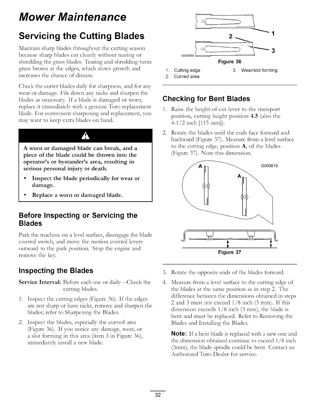
Checking the Tire Pressure
Service Interval: Every 25 hours--Check tire pressure.
Maintain the air pressure in the front and rear tires as
specified. Uneven tire pressure can cause uneven cut.
Check the pressure at the wflve stem (Figure 35). Check
the tires when they are cold to get the most accurate
pressure reading.
Rear Tires: 13 psi (90 kPa)
Front Tires (caster wheels): 35 psi (241 kPa)
G000554
Figure 35
1. Valve stem
31
Mower Maintenance
Servicing the Cutting Blades
Maintain sharp blades throughout the cutting season
because sharp blades cut cleanly without tearing or
shredding the grass blades. Tearing and shredding turns
grass brown at the edges, which slows growth and
increases the chance of disease.
Check the cutter blades daily for sharpness, and for any
wear or damage. File down any nicks and sharpen the
blades as necessar 7 If a blade is damaged or worn,
replace it immediately vdth a genuine Toro replacement
blade. For convenient sharpening and replacement, you
may want to keep extra blades on hand.
A worn or damaged blade can break, and a
piece of the blade could be thrown into the
operator's or bystander's area, resulting in
serious personal injury or death.
• Inspect the blade periodically for wear or
damage.
• Replace a worn or damaged blade.
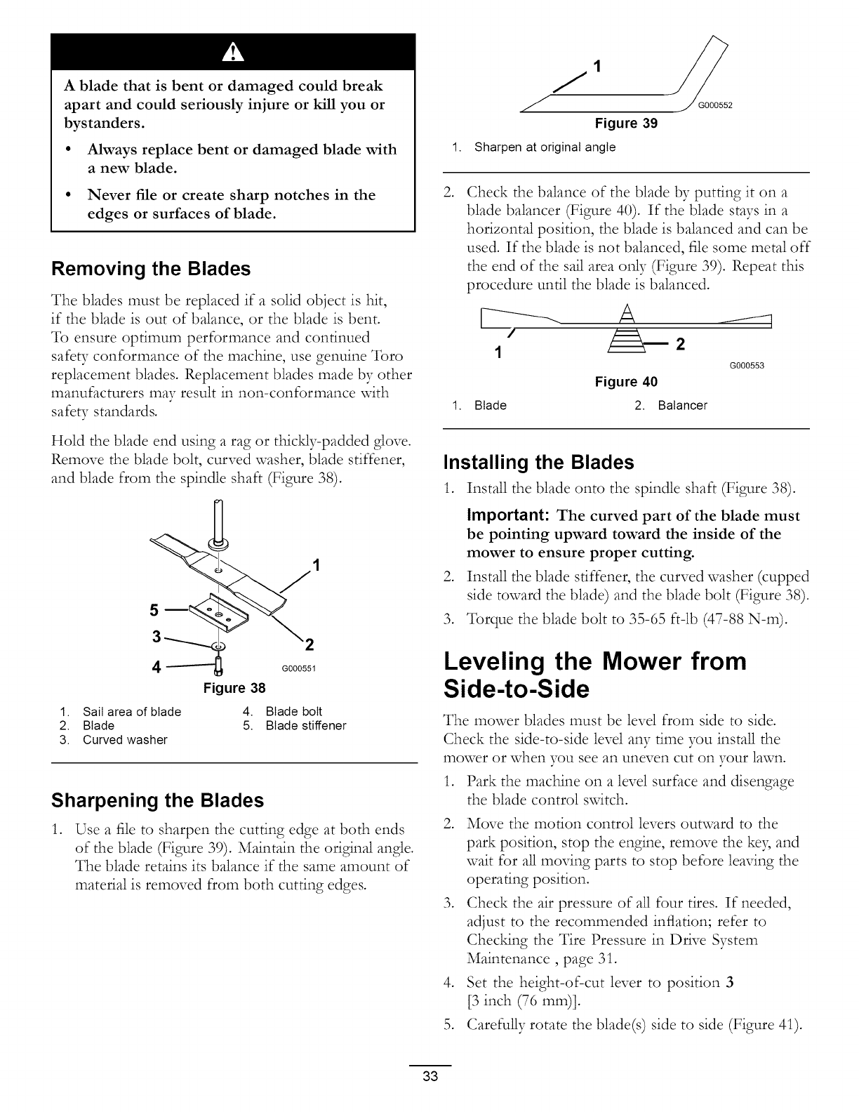
2_
G000550
1. Cutting edge
2. Curved area
Figure 36
3. Wear/slot forming
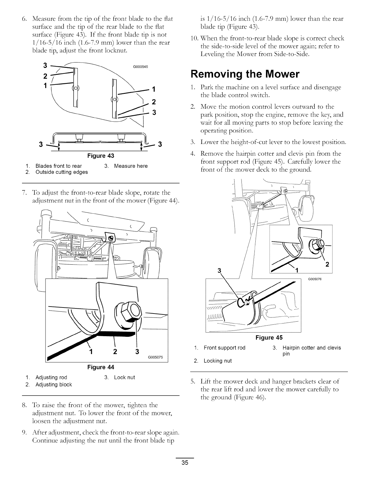
Checking for Bent Blades
1. Raise the height-of-cut lever to the transport
position, cutting height position 4.5 (also the
4-1/2 inch [115 mm]).
,Rotate the blades until the ends face forward and
backward (Figure 37). Measure from a level surface
to the cutting edge, position A, of the blades
(Figure 37). Note this dimension.
G000619
(o)
Before Inspecting or Servicing the
Blades
Park the machine on a level surface, disengage the blade
control svdtch, and move the motion control levers
outward to the park position. Stop the engine and
remove the ke> Figure 37
Inspecting the Blades
Service Interval: Before each use or daily--Check the
cutting blades.
,
,
Inspect the cutting edges (Figure 36). If the edges
are not sharp or have nicks, remove and sharpen the
blades; refer to Sharpening the Blades.
Inspect the blades, especially the curved area
(Figure 36). If you notice any damage, wear, or
a slot forming in this area (item 3 in Figure 36),
immediately install a new blade.
,
4.
Rotate the opposite ends of the blades forward.
Measure from a level surface to the cutting edge of
the blades at the same position as in step 2. The
difference between the dimensions obtained in steps
2 and 3 must not exceed 1/8 inch (3 mm). If this
dimension exceeds 1/8 inch (3 mm), the blade is
bent and must be replaced. Refer to Removing the
Blades and Installing the Blades.
Note: Ira bent blade is replaced vdth a new one and
the dimension obtained continue to exceed 1/8 inch
(3mm), the blade spindle could be bent. Contact an
Authorized Toro Dealer for service.
32
A bladethat is bent or damagedcould break
apartand could seriouslyinjure or kill you or
bystanders.
• Always replace bent or damaged blade with
a new blade.
• Never file or create sharp notches in the
edges or surfaces of blade.
Removing the Blades
The blades must be replaced if a solid object is hit,
if the blade is out of balance, or the blade is bent.
To ensure optimum performance and continued
safety conformance of the machine, use genuine Toro
replacement blades. Replacement blades made by other
manufacturers may result in non-conformance with
safety standards.
Hold the blade end using a rag or thickly-padded glove.
Remove the blade bolt, curved washer, blade stiffener,
and blade from the spindle shaft (Figure 38).
5
4
1. Sail area of blade
2. Blade
3. Curved washer
G000551
Figure 38
4. Blade bolt
5. Blade stiffener
Sharpening the Blades
,Use a file to sharpen the cutting edge at both ends
of the blade (Figure 39). Maintain the original angle.
The blade retains its balance if the same amount of
material is removed from both cutting edges.
Figure 39
1. Sharpen at original angle
G000552
,Check the balance of the blade by putting it on a
blade balancer (Figure 40). If the blade stays in a
horizontal position, the blade is balanced and can be
used. If the blade is not balanced, file some metal off
the end of the sail area only (Figure 39). Repeat this
procedure until the blade is balanced.
1
Figure 40
1. Blade 2. Balancer
G000553
Installing the Blades
1. Install the blade onto the spindle shaft (Figure 38).
,
,
Important: The curved part of the blade must
be pointing upward toward the inside of the
mower to ensure proper cutting.
Install the blade stiffener, the curved washer (cupped
side toward the blade) and the blade bolt (Figure 38).
Torque the blade bolt to 35-65 ft-lb (47-88 N-m).
Leveling the Mower from
Side-to-Side
The mower blades must be level from side to side.
Check the side-to-side level any time you instal] the
mower or when you see an uneven cut on your lawn.
1. Park the machine on a level surface and disengage
the blade control switch.
2. Move the motion control levers outward to the
park position, stop the engine, remove the keB and
wait for all moving parts to stop before leaving the
operating position.
3. Check the air pressure of all four tires. If needed,
adjust to the recommended inflation; refer to
Checking the Tire Pressure in Drive System
Maintenance, page 31.
4. Set the height-of-cut lever to position 3
[3 inch (76 mm)].
5. Carefully rotate the blade(s) side to side (Figure 41).
33

1 G000541
1.
2.
3
a.J w .... w p..-a
Figure 41
Blades side to side 3. Measure here
Outside cutting edges
,Measure between the outside cutting edges and
the flat surface (Figure 41). If both measurements
are not within 3/16 inch (5 mm), an adjustment is
required; continue with this procedure.
7. Move the left side of the machine. Loosen, but
do not remove, the rear loc_ng nut on the hanger
bracket (Figure 42).
,Loosen the side loc_ng nut on the hanger bracket
just enough to allow the eccentric plate to be adjusted
(Figure 42). Use a 3/8 inch drive extension on a
socket wrench to manipulate the eccentric plate. Use
the wrench to reposition the height of the mower
deck and adjust to the desired height.
9. Stop the deck at the adjusted position and tighten
the side loc_ng nut on the hanger bracket to hold
the new position (Figure 42).
10. Continue leveling the deck by chec_ng the
front-to-rear blade slope; refer to Adjusting the
Front-to-Rear Blade Slope.
1
6
5
G005074
2
Figure 42
1. Hanger bracket 4. Eccentric adjustment plate
2. Rear locking nut 5. Socket wrench hole
3. Side locking nut 6. Socket wrench with 3/8
inch extension
Adjusting the Front-to-Rear
Blade Slope
Check the front-to-rear blade level any time you install
the mower. If the front of the mower is more than
5/16 inch (7.9 ram) lower than the rear of the mower,
adjust the blade level using the follovdng instructions:
1. Park the machine on a level surface and disengage
the blade control svdtch.
,
,
,
Move the motion control levers outward to the
park position, stop the engine, remove the key and
wait for all moving parts to stop before leaving the
operating position.
Check the air pressure of all four tires. If needed,
adjust to the recommended inflation; refer to
Chec_ng the Tire Pressure in Drive System
Maintenance, page 31.
Check and adjust the side-to-side blade level if you
have not checked the setting; refer to Leveling the
Mower from Side-to-Side.
5. Set the height-of-cut at position 3 [3 inch (76 ram)]
and carefu_y rotate the blades so they are facing
front to rear (Figure 43).
34
,
1.
2.
,
,
,
Measure from the tip of the front blade to the flat
surface and the tip of the rear blade to the flat
surface (Figure 43). If the front blade tip is not
1/16-5/16 inch (1.6-7.9 ram) lower than the rear
blade tip, adjust the front locM_ut.
321_ _1G°°°545
3
3
Figure 43
Blades front to rear 3. Measure here
Outside cutting edges
3
To adjust the front-to-rear blade slope, rotate the
adjustment nut in the front of the mower (Figure 44).
¢
3G005075
Figure 44
1. Adjusting rod
2. Adjusting block
3. Lock nut
To raise the front of the mower, tighten the
adjustment nut. To lower the front of the mower,
loosen the adjustment nut.
After adjustment, check the front-to-rear slope again.
Continue adjusting the nut until the front blade tip
is 1/16-5/16 inch (1.6-7.9 ram) lower than the rear
blade tip (Figure 43).
10. When the front-to-rear blade slope is correct check
the side-to-side level of the mower again; refer to
Leveling the Mower from Side-to-Side.
Removing the Mower
1. Park the machine on a level surface and disengage
the blade control switch.
,
,
4.
Move the motion control levers outward to the
park position, stop the engine, remove the ke3, and
wait for all moving parts to stop before leaving the
operating position.
Lower the height-of-cut lever to the lowest position.
Remove the hairpin cotter and clevis pin from the
front support rod (Figure 45). Carefully lower the
front of the mower deck to the ground.
1. Front support rod
2. Locking nut
!
G005076
Figure 45
3. Hairpin cotter and clevis
pin
5. Lift the mower deck and hanger brackets clear of
the rear lift rod and lower the mower carefully to
the ground (Figure 46).
35
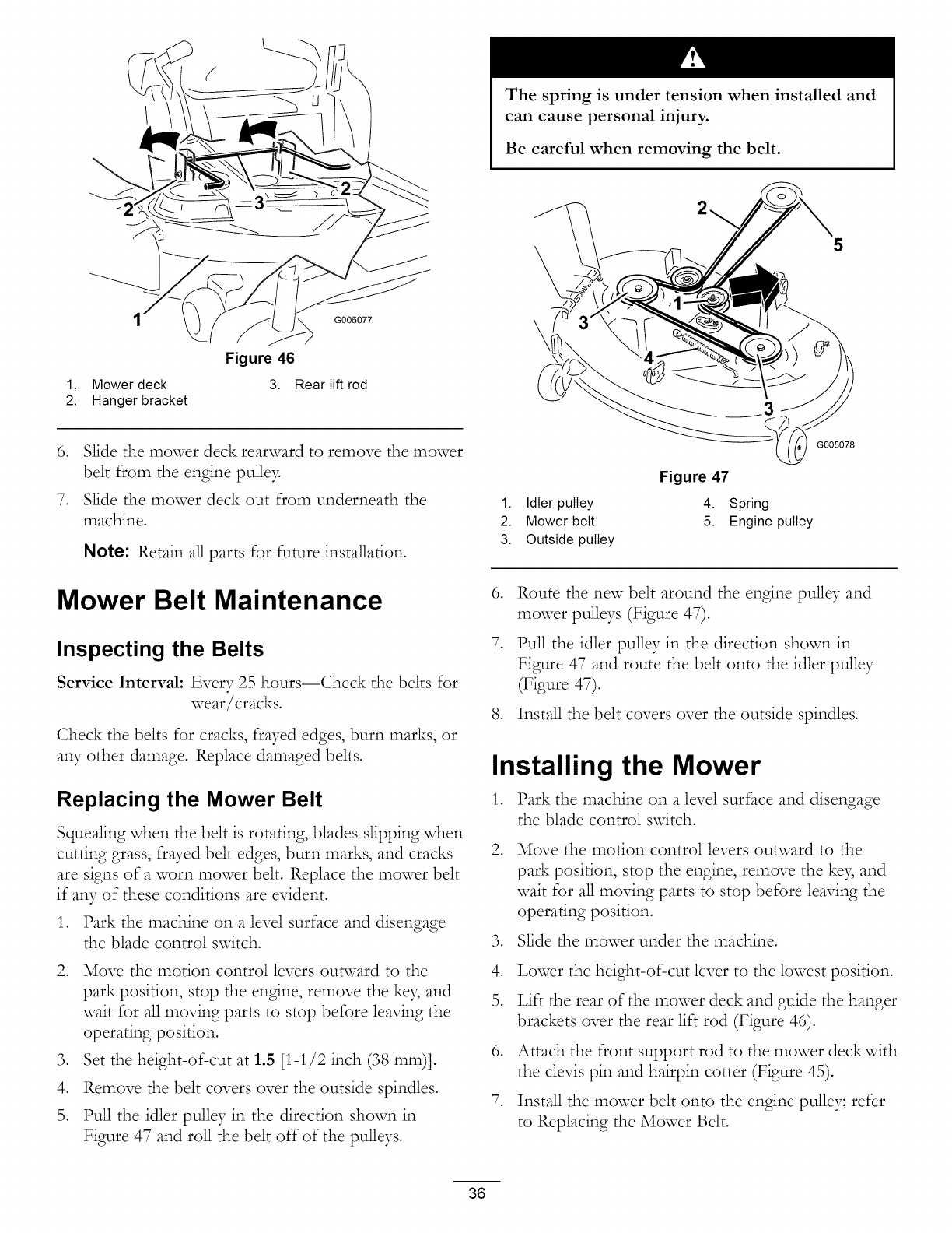
1. Mower deck
2. Hanger bracket
G005077
Figure 46
3. Rear lift rod
6. Slide the mower deck rearward to remove the mower
belt from the engine puEe?_
7. Slide the mower deck out from underneath the
machine.
Note: Retain all parts for future installation.
Mower Belt Maintenance
Inspecting the Belts
Service Interval: Every 25 hours--Check the belts for
wear/cracks.
Check the belts for cracks, frayed edges, burn marks, or
any other damage. Replace damaged belts.
Replacing the Mower Belt
Squealing when the belt is rotating, blades slipping when
cutting grass, frayed belt edges, burn marks, and cracks
are signs of a worn mower belt. Replace the mower belt
if any of these conditions are evident.
1. Park the machine on a level surface and disengage
the blade control switch.
2. Move the motion control levers outward to the
park position, stop the engine, remove the keB and
wait for all moving parts to stop before leaving the
operating position.
3. Set the height-of-cut at 1.5 [1-1/2 inch (38 mm)].
4. Remove the belt covers over the outside spindles.
5. Pull the idler pulley in the direction shown in
Figure 47 and roll the belt off of the pulleys.
The spring is under tension when installed and
can cause personal injury.
Be careful when removing the belt.
\5
1. Idler pulley
2. Mower belt
3. Outside pulley
Figure 47
4. Spring
5. Engine pulley
G005078
,
,
Route the new belt around the engine puEey and
mower puEeys (Figure 47).
Pull the idler pulley in the direction shown in
Figure 47 and route the belt onto the idler pulley
(Figure 47).
8. Install the belt covers over the outside spindles.
Installing the Mower
1. Park the machine on a level surface and disengage
the blade control switch.
,Move the motion control levers outward to the
park position, stop the engine, remove the key and
wait for all moving parts to stop before leaving the
operating position.
3. Slide the mower under the machine.
4. Lower the height-of-cut lever to the lowest position.
5. Lift the rear of the mower deck and guide the hanger
brackets over the rear lift rod (Figure 46).
6. Attach the front support rod to the mower deck with
the clevis pin and hairpin cotter (Figure 45).
7. Install the mower belt onto the engine pulley; refer
to Replacing the Mower Belt.
36
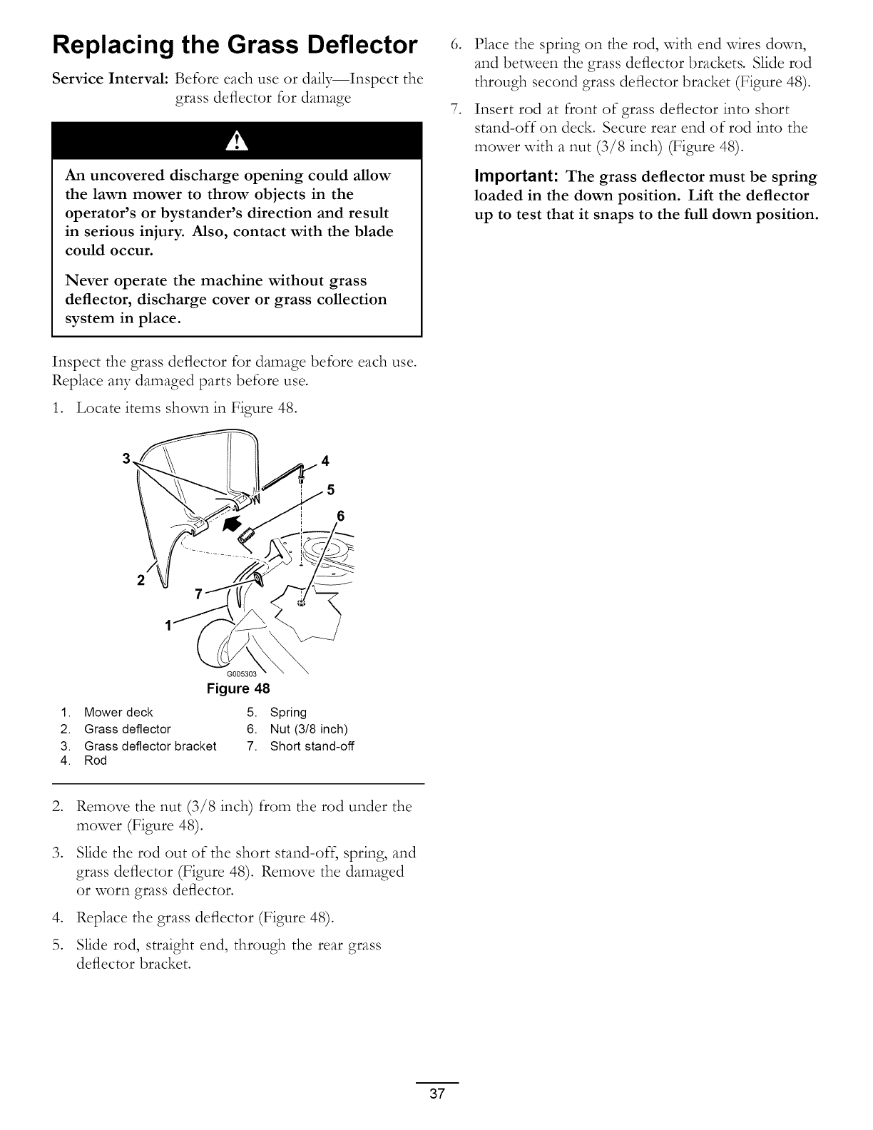
Replacing the Grass Deflector
Service Interval: Before each use or daily--Inspect the
grass deflector for damage
An uncovered discharge opening could allow
the lawn mower to throw objects in the
operator's or bystander's direction and result
in serious injury. Also, contact with the blade
could occur.
Never operate the machine without grass
deflector, discharge cover or grass collection
system in place.
,
,
Place the spring on the rod, with end wires down,
and between the grass deflector brackets• Slide rod
through second grass deflector bracket (Figure 48).
Insert rod at front of grass deflector into short
stand-off on deck. Secure rear end of rod into the
mower with a nut (3/8 inch) (Figure 48)•
Important: The grass deflector must be spring
loaded in the down position. Lift the deflector
up to test that it snaps to the full down position.
Inspect the grass deflector for damage before each use.
Replace any damaged parts before use.
1• Locate items shown in Figure 48.
,4
5
6
G005303
Figure 48
1. Mower deck 5. Spring
2. Grass deflector 6. Nut (3/8 inch)
3. Grass deflector bracket 7. Short stand-off
4. Rod
,
,
,
Remove the nut (3/8 inch) from the rod under the
mower (Figure 48)•
Slide the rod out of the short stand-off, spring, and
grass deflector (Figure 48)• Remove the damaged
or worn grass deflector•
Replace the grass deflector (Figure 48).
Slide rod, straight end, through the rear grass
deflector bracket.
37
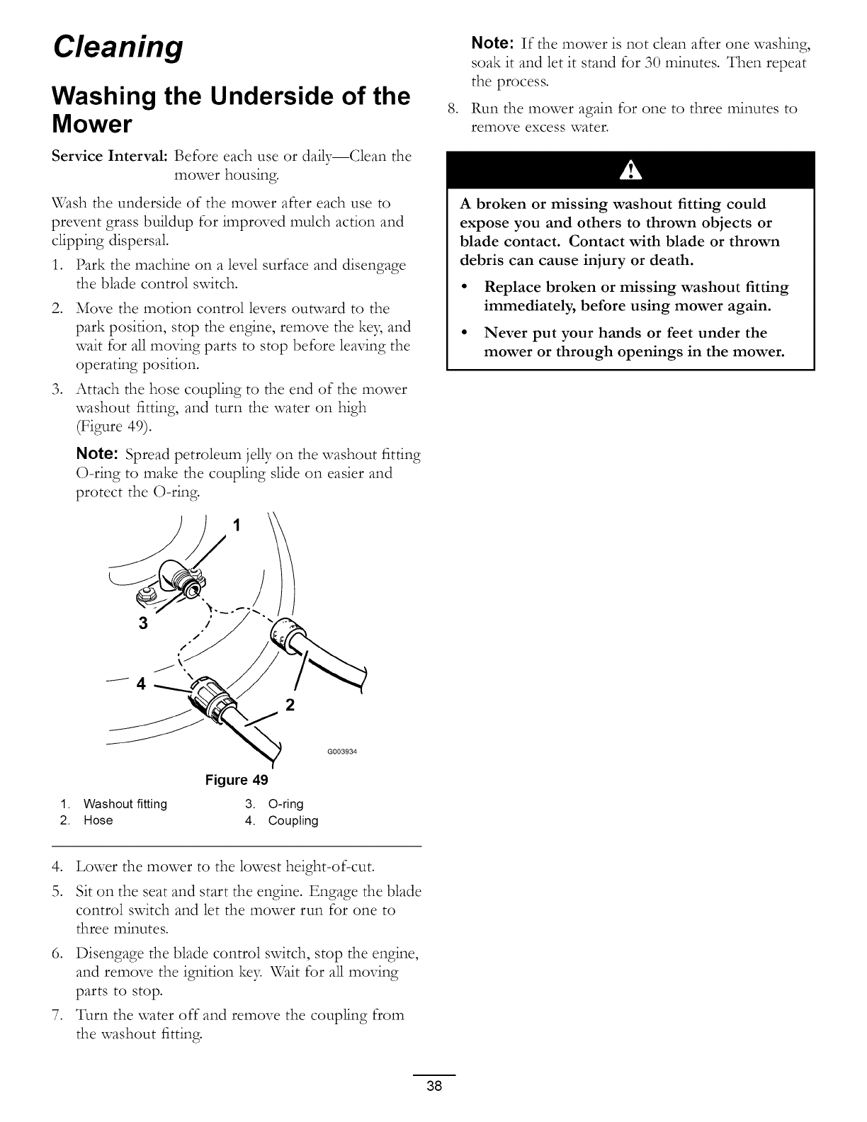
Cleaning
Washing the Underside of the
Mower
Service Interval: Before each use or daily--Clean the
mower housing.
\_hsh the underside of the mower after each use to
prevent grass buildup for improved mulch action and
clipping dispersal
1. Park the machine on a level surface and disengage
the blade control switch.
2• Move the motion control levers outward to the
park position, stop the engine, remove the ke B and
wait for all moving parts to stop before leaving the
operating position•
3. Attach the hose coupling to the end of the mower
washout fitting, and turn the water on high
(Figure 49)•
Note: Spread petroleum jelly on the washout fitting
O-ring to make the coupling slide on easier and
protect the O-ring.
3
,
Note: If the mower is not clean after one washing,
soak it and let it stand for 30 minutes. Then repeat
the process.
Run the mower again for one to three minutes to
remove excess water.
A broken or missing washout fitting could
expose you and others to thrown objects or
blade contact. Contact with blade or thrown
debris can cause injury or death.
• Replace broken or missing washout fitting
immediately, before using mower again.
• Never put your hands or feet under the
mower or through openings in the mower.
Figure 49
1. Washout fitting 3. O-ring
2. Hose 4. Coupling
G003934
,Lower the mower to the lowest height-of-cut•
Sit on the seat and start the engine. Engage the blade
control switch and let the mower run for one to
three minutes.
6. Disengage the blade control switch, stop the engine,
and remove the ignition ke3= Wait for all moving
parts to stop.
7. Turn the water off and remove the coupling from
the washout fitting.
38

Storage
Cleaning and Storage
1• Disengage the blade control switch, move the
motion controls outward to the park position, stop
the engine, and remove the ke7
2. Remove grass clippings, dirt, and grime from the
external parts of the entire machine, especially the
engine• Clean dirt and chaff from the outside of the
engine cylinder head fins and blower housing.
Important: You can wash the machine with
mild detergent and water. Do not pressure
wash the machine. Avoid excessive use of
water, especially near the control panel, engine,
hydraulic pumps, and motors.
3• Service the air cleaner; refer to Servicing the Air
Cleaner in Engine Maintenance, page 24.
4. Grease and oil the machine; refer to Lubrication,
page 23.
Change the crankcase oil and filter; refer to Servicing
the Engine Oil in Engine Maintenance, page 24.
6. Check the tire pressure; refer to Checking the Tire
Pressure in Drive System Maintenance, page 31.
7. Charge the battery; refer to Servicing the Battery
in Electrical System Maintenance, page 29.
8. Check the condition of the blades; refer to Servicing
the Cutting Blades in Mo,,erMaiztezazce, page 32.
9. Prepare the machine for storage when non-use
occurs over 30 days. Prepare the machine for storage
as follows.
10. Add a petroleum based stabilizer/conditioner to the
fuel in the tank. Follow the mixing instructions from
the stabilizer manufacturer. Do not use an alcohol
based stabilizer (ethanol or methanol).
Note: A fuel stabilizer/conditioner is most effective
when mixed with fresh gasoline and used at all times.
Run the engine to distribute the conditioned fuel
through the fuel system (5 minutes).
Stop the engine, allow it to cool, and drain the fuel
tank; refer to Draining the Fuel Tank in Fuel System
Maintenance, page 28.
Restart the engine and run it until it stops•
Choke the engine. Start and run the engine until it
will not start.
Dispose of fuel properl> Recycle pursuant to local
codes•
11.
12.
13.
14.
15.
16.
17.
Important: Do not store stabilizer/conditioned
gasoline over 30 days.
Remove the spark plug(s) and check lts condition;
refer to Servicing the Spark Plug in Engine
Maintenance , page 24. With the spark plug(s)
removed from the engine, pour two tablespoons of
engine oil into the spark plug hole• Use the starter
to crank the engine and distribute the oil inside the
cylinder. Instal] the spark plug(s). Do not instal] the
wire on the spark plug(s).
Clean any dirt and chaff from the top of the mower.
Scrape any heaxT buildup of grass and dirt from the
underside of the mower, then wash the mower with
a garden hose•
Check the condition of the drive and mower belts.
Check and tighten all bolts, nuts, and screws. Repair
or replace any part that is worn or damaged•
Paint all scratched or bare metal surfaces• Paint is
available from your Authorized Service Dealer.
Store the machine in a dean, dry garage or storage
area. Remove the key from the ignition switch and
keep it in a memorable place. Cover the machine to
protect it and keep it dean.
39

Troubleshooting
Problem
The engine overheats.
Possible Cause Corrective Action
1. The engine load is excessive.
2. The oil level in the crankcase is low.
3. The cooling fins and air passages
under the engine blower housing are
plugged.
4. The air cleaner is dirty.
5. Dirt, water, or stale fuel is in fuel
system.
The starter does not crank 1.
2.
3.
4.
5.
6.
7.
The engine will not start, starts hard, or 1.
fails to keep running. 2.
3.
4.
5.
6.
7.
8.
9.
The engine loses power. 1.
2.
3.
4.
The machine does not drive.
The blade control switch is engaged.
The motion control levers are not in the
park position.
The operator is not seated.
The battery is dead.
The electrical connections are corroded
or loose.
A fuse is blown.
A relay or switch is damaged.
The fuel tank is empty.
The choke is not on.
The air cleaner is dirty.
The spark plug wire(s) is loose or
disconnected.
The spark plug(s) is pitted, fouled, or
the gap is incorrect.
There is dirt in fuel filter.
Dirt, water, or stale fuel is in fuel
system.
There is incorrect fuel in the fuel tank.
The oil level in the crankcase is low.
The engine load is excessive.
The air cleaner is dirty.
The oil level in the crankcase is low.
The cooling fins and air passages
under the engine blower housing are
plugged.
5. The spark plug(s) is pitted, fouled, or
the gap is incorrect.
6. The vent in the fuel cap is closed.
7. There is dirt in the fuel filter.
8. Dirt, water, or stale fuel is in the fuel
system.
9. There is incorrect fuel in the fuel tank.
1. The bypass valves are open
2. The traction belts are worn, loose, or
broken.
3. The traction belts are off of the pulleys.
4. The transmission has failed.
1. Reduce ground speed.
2. Add oil to the crankcase.
3. Remove the obstruction from the
cooling fins and air passages.
4. Clean or replace the air cleaner
element.
5. Contact an Authorized Service Dealer
1.
2.
3.
4.
5.
6.
7.
1.
2.
3.
4.
5.
6.
7.
8.
9.
1.
2.
3.
4.
Move the blade control switch to
Disengaged.
Move the motion control levers outward
to the park position.
Sit on the seat.
Charge the battery.
Check the electrical connections for
good contact.
Replace the fuse.
Contact an Authorized Service Dealer.
Fill the fuel tank.
Move the choke lever to On.
Clean or replace the air cleaner
element.
Install the wire(s) on the spark plug.
Install a new, correctly gapped spark
plug(s).
Replace the fuel filter.
Contact an Authorized Service Dealer.
Drain the tank and replace the fuel with
the proper type.
Add oil to the crankcase.
Reduce ground speed.
Clean the air cleaner element.
Add oil to the crankcase.
Remove the obstruction from the
cooling fins and air passages.
5. Install a new, correctly gapped spark
plug(s).
6. Open the vent in the fuel cap.
7. Replace the fuel filter.
8. Contact an Authorized Service Dealer.
9. Drain the tank and replace the fuel with
the proper type.
1. Close the tow valves.
2. Contact an Authorized Service Dealer.
3. Contact an Authorized Service Dealer.
4. Contact an Authorized Service Dealer.
40
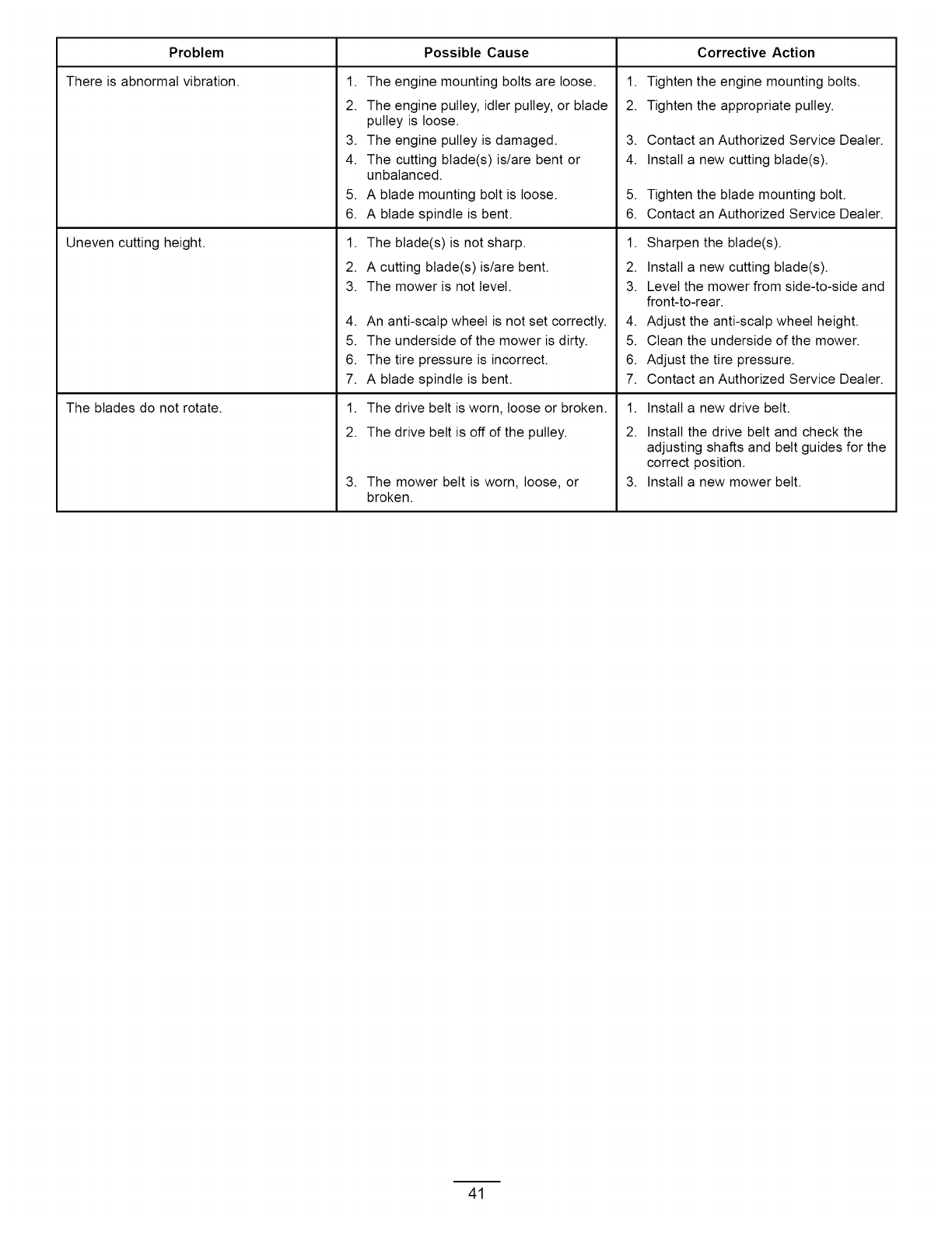
Problem Possible Cause
There is abnormal vibration.
Uneven cutting height.
The blades do not rotate.
1. The engine mounting bolts are loose.
2. The engine pulley, idler pulley, or blade
pulley is loose.
3. The engine pulley is damaged.
4. The cutting blade(s) is/are bent or
unbalanced.
5. A blade mounting bolt is loose.
6. A blade spindle is bent.
1. The blade(s) is not sharp.
2. A cutting blade(s)is/are bent.
3. The mower is not level.
4. An anti-scalp wheel is not set correctly.
5. The underside of the mower is dirty.
6. The tire pressure is incorrect.
7. A blade spindle is bent.
1. The drive belt is worn, loose or broken.
2. The drive belt is off of the pulley.
3. The mower belt is worn, loose, or
broken.
Corrective Action
1. Tighten the engine mounting bolts.
2. Tighten the appropriate pulley.
3. Contact an Authorized Service Dealer.
4. Install a new cutting blade(s).
5. Tighten the blade mounting bolt.
6. Contact an Authorized Service Dealer.
1. Sharpen the blade(s).
2. Install a new cutting blade(s).
3. Level the mower from side-to-side and
front-to-rear.
4. Adjust the anti-scalp wheel height.
5. Clean the underside of the mower.
6. Adjust the tire pressure.
7. Contact an Authorized Service Dealer.
1.
2.
3.
Install a new drive belt.
Install the drive belt and check the
adjusting shafts and belt guides for the
correct position.
Install a new mower belt.
41
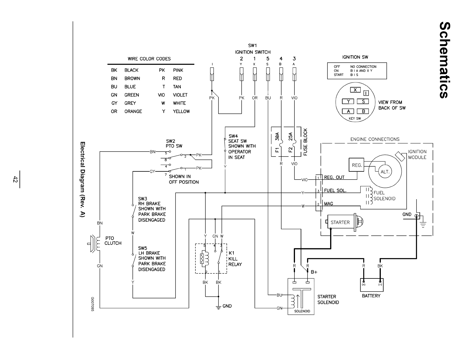
I'll
P.q.
tim
3
A
;;1:1
.<
BN
GN
oo
g
WIRE COLOR CODES
BK BLACK PK
BN BROWN R
BU BLUE T
GN GREEN VIO
GY GREY W
OR ORANGE Y
PINK
RED
TAN
VIOLET
WHITE
YELLOW
PK
SW2
PTO SW
BN_pK--
7 SHOWN IN
OFF POSITION
PTO
CLUTCH
SW3
RH BRAKE
SHOWN WITH
PARK BRAKE
DISENGAGED
w
SW5
LH BRAKE
SHOWN WITH
PARK BRAKE
DISENGAGED
Y
SWl
IGNITION SWITCH
2 1 5 4 3
Y X S B A
ll!ll
PK OR BU R VlO
__1
SW4
SEAT SW
SHOWN WITH
OPERATOR
IN SEAT
Y
1
IT
Y GN W
r ....... 1
_f_:
KILL
I
,, ',RELAY
II_ __
BK BK
l!oeo
r--
½
R
_N( m
P
VlO
LVIO
Y
w
IGNITION SW
OFF NO CONNECTION
ON B I A AND X Y
START B I S
VIEW FROM
BACK OF SW
ENGINE CONNECTIONS
F
3
12
REG. OUT
FUEL SOL.
MAG
FUEL
I
_ STARTER II_
I
!
R R
1"iB+
--iL__ STARTER
SOLENOID
I !
R BK
BATTERY
IGNITION
MODULE
GND
!1)
3
ll}
I/1
_z
i

Notes:
43
TITAN Z and
TimeCutter
Z Mowers
The Taro Total Coverage Guarantee
A Three-Year Limited Warranty (Limited Warranty for
Commercial Use)
Conditions and Products Covered
The Taro Company and its affiliate, Taro Warranty Company,
pursuant to an agreement between them, jointly promise to
repair any Taro Product used for normal residential purposes*
if defective in materials or workmanship. The following time
periods apply from the date of purchase:
Products
TITAN Z
Mowers and Attachments
TimeCutter Z
Mowers and Attachments
Warranty Period
3year limited warranty
3year limited warranty
All Batteries 1year limited warranty
If for any reason you are dissatisfied with the Service Dealer's
analysis or with the assistance provided, contact us at:
Customer Care Department, Consumer Division
Taro Warranty Company
8111 Lyndale Avenue South
Bloomington, MN 55420-1196
Toll Free: 866-216-6029 (U.S. customers)
Toll Free: 866-216-6030 (Canada customers)
Owner Responsibilities
You must maintain your Taro Product by following the
maintenance procedures described in the Operator's Manual.
Such routine maintenance, whether performed by a dealer or by
you, is at your expense.
This warranty includes the cost of parts and labor, but you must
pay the cost of transportation to and from the servicing dealer.
This warranty applies to consumer TITAN Z and TimeCutter Z
mowers and attachments.
* Normal residential purposes means use of the product on
the same lot as your home. Use at more than one location is
considered commercial use, and the commercial use warranty
would apply.
Limited Warranty for Commercial Use
Taro Consumer Products and attachments used for commercial,
institutional, or rental use are warranted against defects in
materials or workmanship for the following time periods from the
date of purchase:
Products
Air Cooled Gas Engines
All other items
Warranty Period
90 day limited warranty
30 day limited warranty
Instructions for Obtaining Warranty Service
If you think that your Taro Product contains a defect in materials
or workmanship, follow this procedure:
1. Contact any Taro Authorized or Master Service Dealer
to arrange service at their dealership. To locate a dealer
convenient to you, refer to the Yellow Pages of your
telephone directory (look under "Lawn Mowers") or access
our web site at www.Toro.com. U.S. Customers may also
call toll free: 866-854-9035 to use our 24-hour Taro dealer
locator system.
2. Bring the product and your proof of purchase (sales receipt)
to the Service Dealer.
Items and Conditions Not Covered
There is no other express warranty except for special emission
system coverage on some products. This express warranty does
not cover:
• Cost of regular maintenance service or parts, such as filters,
fuel, lubricants, tune-up parts, blade sharpening, brake and
clutch adjustments.
• Any product or part which has been altered or misused
or required replacement or repair due to normal wear,
accidents, or lack of proper maintenance.
• Repairs necessary due to improper fuel, contaminants in the
fuel system, or failure to properly prepare the fuel system
prior to any period of non-use over three months.
• Pickup and delivery charges to and from an Authorized Taro
Service Dealer.
General Conditions
All repairs covered by this warranty must be performed by an
Authorized Taro Service Dealer using Taro approved replacement
parts.
Repair by an Authorized Toro Service Dealer is your sole
remedy under this warranty.
Neither The Toro Company nor Toro Warranty Company
is liable for indirect, incidental or consequential
damages in connection with the use of the Toro Products
covered by this warranty, including any cost or expense
of providing substitute equipment or service during
reasonable periods of malfunction or non-use pending
completion of repairs under this warranty.
Some states do not allow exclusion of incidental or
consequential damages, so the above exclusion and
limitations may not apply to you.
This warranty gives you specific legal rights, and you
may also have other rights which vary from state to
state.
Countries Other than the United States or Canada
Customers who have purchased Taro products exported from the United States or Canada should contact their Taro Distributor
(Dealer) to obtain guarantee policies for your country, province, or state. If for any reason you are dissatisfied with your Distributor's
service or have difficulty obtaining guarantee information, contact the Taro importer. If all other remedies fail, you may contact us
at Taro Warranty Company.
374-0124 Rev B

Form No. 3356-526 Rev A
Count on it.
0
O
m
m
Cortac_sped con conductor
TimeCutter ®Z4200
N ° de modelo 74360--N ° Serie 270000001 y superiores
G005051
Registre su producto en www.Toro.com Traducci6n del original (ES)
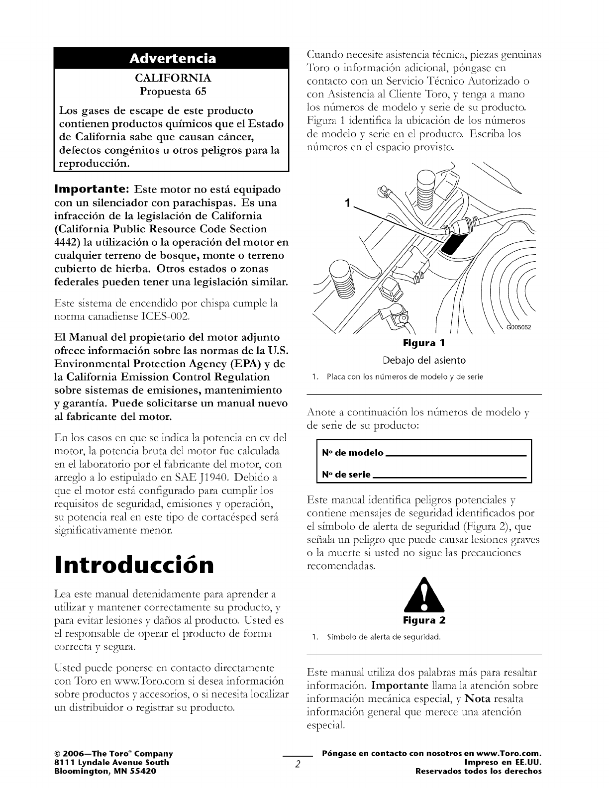
CALIFORNIA
Propuesta 65
Los gases de escape de este producto
contienen productos quimicos que el Estado
de California sabe que causan cfincer,
defectos cong_nitos u otros peligros para la
reproducci6n.
Importante: Este motor no estfi equipado
con un silenciador con parachispas. Es una
infracci6n de la legislaci6n de California
(California Public Resource Code Section
4442) la utilizaci6n o la operaci6n del motor en
cualquier terreno de bosque, monte o terreno
cubierto de hierba. Otros estados o zonas
federales pueden tener una legislaci6n similar.
Este sistema de encendido por chispa cumple la
norma canadiense ICES-002.
E1 Manual del propietario del motor adjunto
ofrece informaci6n sobre las normas de la U.S.
Environmental Protection Agency (EPA) yde
la California Emission Control Regulation
sobre sistemas de emisiones, mantenimiento
y garant{a. Puede solicitarse un manual nuevo
al fabricante del motor.
En los casos en clue se indica la potencia en cv del
motor, la potencia bruta del motor rue calculada
en el laboratorio por el fabricante del motor, con
arreglo s: lo estipulado en SAE J1940. Debido a
clue el motor estfi configurado para cumplir los
requisitos de seguridad, emisiones y operacidn,
su potencia real en este tipo de cortacSsped serfi
significativamente menor.
Introducci6n
Lea este manual detenidamente para aprender a
utilizar y mantener correctamente su producto, y
para evitar lesiones y dafios al producto. Usted es
el responsable de operar el producto de forms:
corrects: y segura.
Usted puede ponerse en contacto directamente
con Toro en :w,,_-,,_:Toro.com si desea informacidn
sobre productos y accesorios, o si necesita localizar
un distribuidor o registrar su producto.
Cuando necesite asistencia tScnica, piezas genuinas
Toro o informacidn adicional, pdngase en
contacto con un Servicio TScnico Autorizado o
con Asistencia al Cliente Toro, y tenga a mano
los nfimeros de modelo y serie de su producto.
Figura 1 identifica la ubicacidn de los nfimeros
de modelo y serie en el producto. Escriba los
nfimeros en el espacio provisto.
].
Figura 1
Debajo del asiento
placacon los n0meros de modelo y de serie
Anote a continuacidn los nfimeros de modelo y
de serie de su producto:
N° de modelo
N° de serie
Este manual identifica peligros potenciales y
contiene mensajes de seguridad identificados pot
el s_mbolo de alerta de seguridad (Figura 2), que
sefiala un peligro que puede causar lesiones graves
o la muerte si usted no sigue las precauciones
recomendadas.
Figura 2
1. S[mbolo de alerta de seguridad.
Este manual utiliza dos palabras msis para resaltar
informacidn. Importante llama la atencidn sobre
informacidn mecJnica especial, y Nota resalta
informacidn general que merece una atencidn
especial.
©2006--The Toro ®Company
8111 Lyndale Avenue South
Bloomington, MN 55420
P6ngase en contacto con nosotros en www.Toro.com.
Impreso en EE.UU.
Reservados todos los derechos

Contenido
Introducci6n ...................................................... 2
Seguridad ............................................................ 4
Pr_cticas de operaci6n segura ............... 4
Seguridad para cortac&pedes Toro
con conductor ..................... 6
Diagrama de pendientes ....................... 8
Pegatinas de seguridad e
instrucciones ...................... 9
E1 producto ....................................................... 12
Controles ......................................... 13
Operaci6n ......................................................... 14
Primero la seguridad .......................... 14
Gasolina recomendada ...................... 14
Verificaci6n del nivel de aceite del
motor ................................ 16
C6mo arrancar el motor ..................... 16
Operaci6n de las cuchillas .................. 17
C6mo parar el motor ......................... 18
E1 sistema de interruptores de
seguridad ........................... 18
Conducci6n hacia adelante y hacia
atrfis .................................. 19
Parada de la mfiquina .......................... 20
Ajuste de la altura de corte .................. 20
Colocaci6n de1 asiento ....................... 20
Ajuste de las palancas de control de
movimiento ....................... 20
Empujar la mfiquina a mano ............... 21
Descarga lateral ................................. 21
Consejos de operaci6n ....................... 22
Mantenimiento .................................................. 24
Calendario recomendado de
mantenimiento ......................... 24
Procedimientos previos al
mantenimiento .......................... 25
C6mo levantar el asiento .................... 25
Acceso a la bateda ............................. 25
Lubricaci6n ............................................... 25
Engrasado de los cojinetes ................. 25
Mantenimiento del motor .......................... 26
Mantenimiento del limpiador de
aire .................................... 26
Mantenimiento del aceite de
motor ................................ 27
Mantenimiento de la buj{a .................. 29
Limpieza de la carcasa del
soplador ............................ 29
Mantenimiento del sistema de
combustible ............................... 30
C6mo cambiar el filtro de
combustible ....................... 30
Mantenimiento del sistema
el&trico .................................... 30
CSmo cargar la bateda ....................... 31
Mantenimiento de los fusibles ............ 32
Mantenimiento del sistema de
transmisi6n ............................... 32
Comprobaci6n de la presi6n de los
neumfiticos ........................ 32
Mantenimiento del cortac&ped ................. 33
Mantenimiento de las cuchillas de
corte .................................. 33
NNelaci6n lateral del
cortac&ped ....................... 34
Ajuste de la inclinaciSn longitudinal
de las cuchillas ................... 35
C6mo retirar el cortac&ped ............... 36
Mantenimiento de la correa del
cortac&ped ....................... 37
C6mo instalar el cortac&ped .............. 38
Cambio del deflector de hierba ........... 38
Limpieza ................................................... 39
C6mo lavar los bajos de1
cortac&ped ....................... 39
Almacenamiento ............................................... 40
Limpieza y almacenamiento ............... 40
Soluci6n de problemas ....................................... 42
Esquemas .......................................................... 47
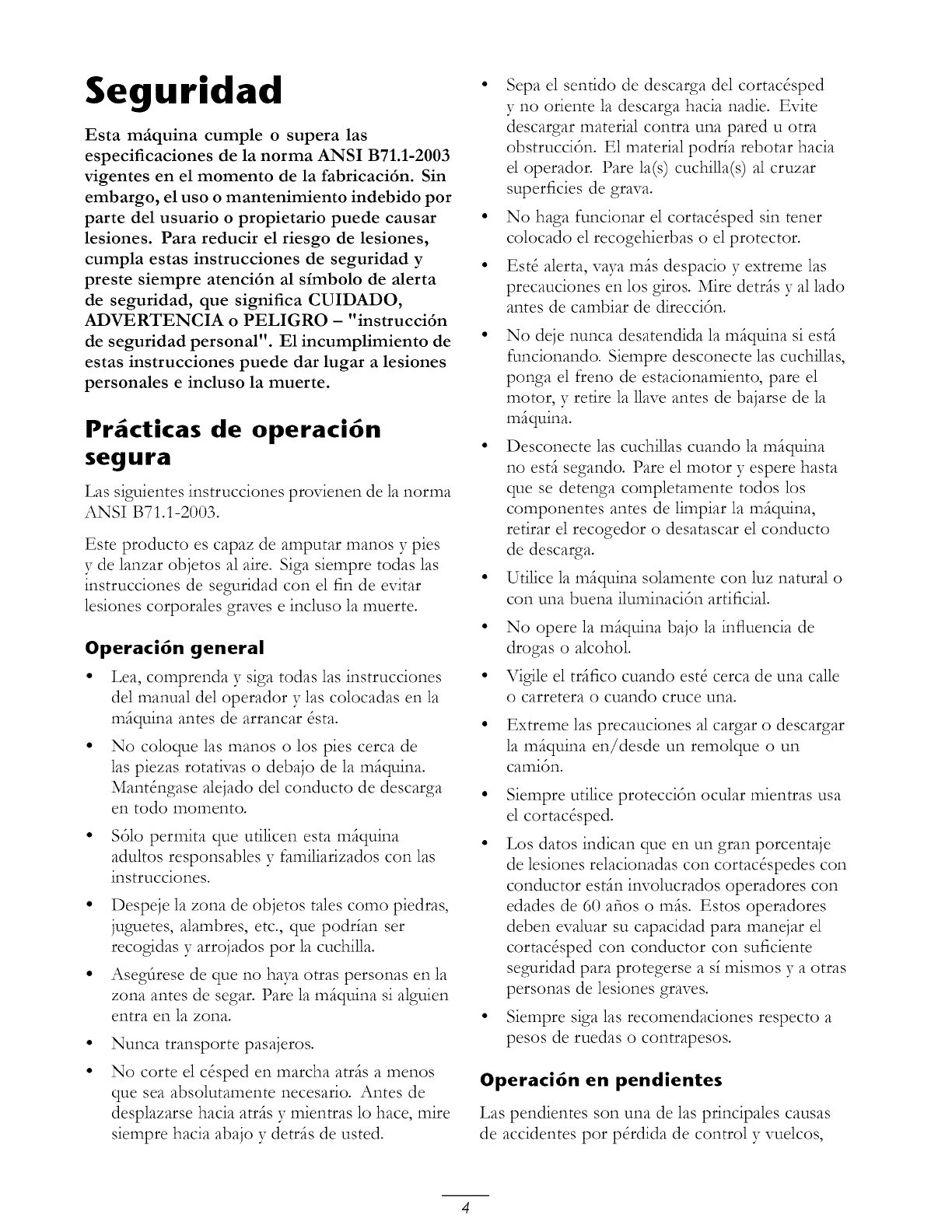
Seguridad
Esta m_quina cumple o supera las
especificaciones de la norma ANSI B71.1-2003
vigentes en el momento de la fabricaci6n. Sin
embargo, el uso o mantenimiento indebido por
parte del usuario o propietario puede causar
lesiones. Para reducir el riesgo de lesiones,
cumpla estas instrucciones de seguridad y
preste siempre atenci6n al simbolo de alerta
de seguridad, que significa CUIDADO,
ADVERTENCIA o PELIGRO - "instrucci6n
de seguridad personal". E1 incumplimiento de
estas instrucciones puede dar lugar a lesiones
personales e incluso la muerte.
Pr cticas de operaci6n
segura
Las siguientes instrucciones provienen de la norma
ANSI B71.1-2003.
Este producto es capaz de amputar manos y pies
y de lanzar objetos al aire. Siga siempre todas las
instrucciones de seguridad con el fin de evitar
lesiones corporales graves e incluso la muerte.
Operaci6n general
• Lea, comprenda 3Tsiga todas las instrucciones
del manual del operador y las colocadas en la
mfiquina antes de arrancar &ta.
• No coloque las manos o los pies cerca de
las piezas rotativas o debajo de la mfiquina.
MantOngase alejado del conducto de descarga
en todo momento.
• $61o permita que utilicen esta mfiquina
adultos responsables y familiarizados con las
instrucciones.
• Despeje la zona de objetos tales como piedras,
juguetes, alambres, etc., que poddan ser
recogidas y arrojados pot la cuchilla.
• Asegfirese de que no haya otras personas en la
zona antes de segar. Pare la mfiquina si algulen
entra en la zona.
Nunca transporte pasajeros.
No corte el c&ped en marcha atrfis a menos
que sea absolutamente necesario. Antes de
desplazarse hacia atrfis y mientras lo hace, mire
siempre hacia abajo y detrfis de usted.
Sepa el sentido de descarga del cortac&ped
y no oriente la descarga hacia nadie. Evite
descargar material contra una pared u otra
obstrucci6n. E1 material podda rebotar hacia
el operador. Pare la(s) cuchina(s)al cruzar
superficies de grava.
• No haga funcionar el cortac&ped sin tener
colocado el recogehierbas o el protector.
• EstO alerta, vaya mils despacio y extreme las
precauciones en los giros. Mire detrfis y al lado
antes de cambiar de direcci6n.
• No deje nunca desatendida la mfiquina si estfi
funcionando. Siempre desconecte las cuchillas,
ponga el freno de estacionamiento, pare el
motor, y retire la llave antes de bajarse de la
mfiquina.
• Desconecte las cuchillas cuando la mfiquina
no estfi segando. Pare el motor y espere hasta
que se detenga completamente todos los
componentes antes de limpiar la miquina,
retirar el recogedor o desatascar el conducto
de descarga.
• Utilice la mfiquina solamente con luz natural o
con una buena iluminaci6n artificial
•No opere la miquina bajo la influencia de
drogas o alcohol.
• Vigile el trifico cuando est8 cerca de una calle
o carretera o cuando cruce una.
Extreme las precauciones al cargar o descargar
la miquina en/desde un remolque o un
cami6n.
• Siempre utilice protecci6n ocular mientras usa
el cortac&ped.
•Los datos indican queen un gran porcentaje
de lesiones relacionadas con cortac&pedes con
conductor estin involucrados operadores con
edades de 60 afios o mils. Estos operadores
deben evaluar su capacidad para manejar el
cortac&ped con conductor con suficiente
seguridad para protegerse a s_mismos y aotras
personas de lesiones graves.
• Siempre siga las recomendaciones respecto a
pesos de ruedas o contrapesos.
Operaci6n en pendientes
Las pendientes son una de las principales causas
de accidentes por p&dida de control y vuelcos,
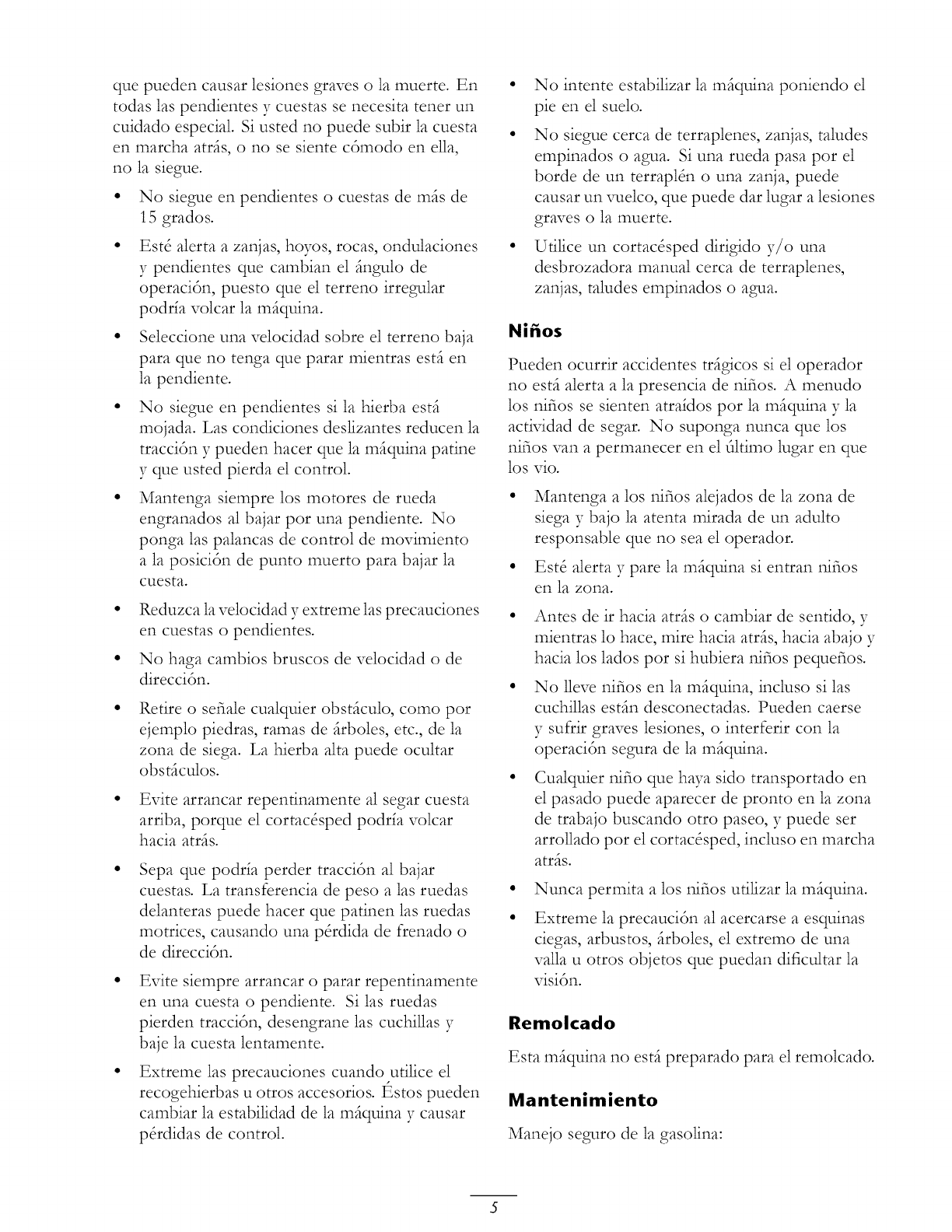
quepuedencausarlesionesgraveso lamuerte.En
todaslaspendientesy cuestassenecesitatenetun
cuidadoespecial.Siustedno puedesubirla cuesta
enmarchaatrfis,o no sesientec6modoenella,
no lasiegue.
No siegueenpendienteso cuestasdemilsde
15grados.
EstOalertaazanjas,hoyos,rocas,ondulaciones
y pendientesquecambianel fingulode
operaci6n,puestoqueel terrenoirregular
poddavolcarlamfiquina.
Seleccioneunavelocidadsobreelterrenobaja
paraqueno tengaquepararmientrasestfien
lapendiente.
No siegueenpendientessila hierbaestfi
mojada.Lascondicionesdeslizantesreducenla
tracci6ny puedenhacerquelam_quinapatine
y queustedpierdaelcontrol.
Mantengasiemprelos motoresde rueda
engranadosalbajarpor unapendiente.No
pongalaspalancasdecontroldemovimiento
alaposici6ndepuntomuertoparabajarla
cuesta.
Reduzcalavelocidady extreme1asprecauciones
encuestaso pendientes.
No hagacambiosbruscosdevelocidado de
direcci6n.
Retireo sefialecualquierobstficulo,comopor
ejemplopiedras,ramasdefirboles,etc.,dela
zonadesiega.La hierba alta puede ocultar
obst_culos.
• Evite arrancar repentinamente al segar cuesta
arriba, porque el cortac&ped podda volcar
hacia atrfis.
Sepa que podda perder tracci6n al bajar
cuestas. La transferencia de peso a 1as ruedas
delanteras puede hacer que patinen las ruedas
motrices, causando una p&dida de frenado o
de direcci6n.
Evite siempre arrancar o parar repentinamente
en una cuesta o pendiente. Si 1as ruedas
pierden tracci6n, desengrane las cuchillas y
baje la cuesta lentamente.
Extreme las precauciones cuando utilice el
recogehierbas u otros accesorios, t_stos pueden
cambiar la estabilidad de la mfiquina y causar
p&didas de control.
No intente estabilizar la mfiquina poniendo el
pie en el suelo.
• No siegue cerca de terraplenes, zanjas, taludes
empinados o agua. Si una rueda pasa por el
borde de un terraplSn o una zanja, puede
causar un vuelco, que puede dar lugar a lesiones
graves o la muerte.
• Utilice un cortac&ped dirigido y/o una
desbrozadora manual cerca de terraplenes,
zanjas, taludes empinados o agua.
Ni_os
Pueden ocurrir accidentes trfigicos si el operador
no est_ alerta a la presencia de nifios. A menudo
los nifios se sienten atra_dos por la m_quina y la
actMdad de segar. No suponga nunca que los
nifios van a permanecer en el filtimo lugar en que
los rio.
Mantenga a los nifios alejados de la zona de
siega y bajo la atenta mirada de un adulto
responsable que no sea el operador.
Est8 alerta y pare la m_quina si entran nifios
en la zona.
Antes de ir hacia atrfis o cambiar de sentido, y
mientras lo hace, mire hacia atrfis, hacia abajo y
hacia los lados por si hubiera nifios pequefios.
No 11evenifios en la mfiquina, incluso si las
cuchillas estfin desconectadas. Pueden caerse
y sufrir graves lesiones, o interferir con la
operaci6n segura de la m_quina.
Cualquier nifio que haya sido transportado en
el pasado puede aparecer de pronto en la zona
de trabajo buscando otro paseo, y puede ser
arrollado por el cortac&ped, incluso en marcha
atr_s.
Nunca permita a los ilifios utilizar la m_quina.
Extreme la precauci6n al acercarse a esquinas
ciegas, arbustos, _rboles, el extremo de una
valla u otros objetos que puedan dificultar la
visi6n.
Remolcado
Esta mfiquina no estfi preparado para el remolcado.
Mantenimiento
Manejo seguro de la gasolina:
5
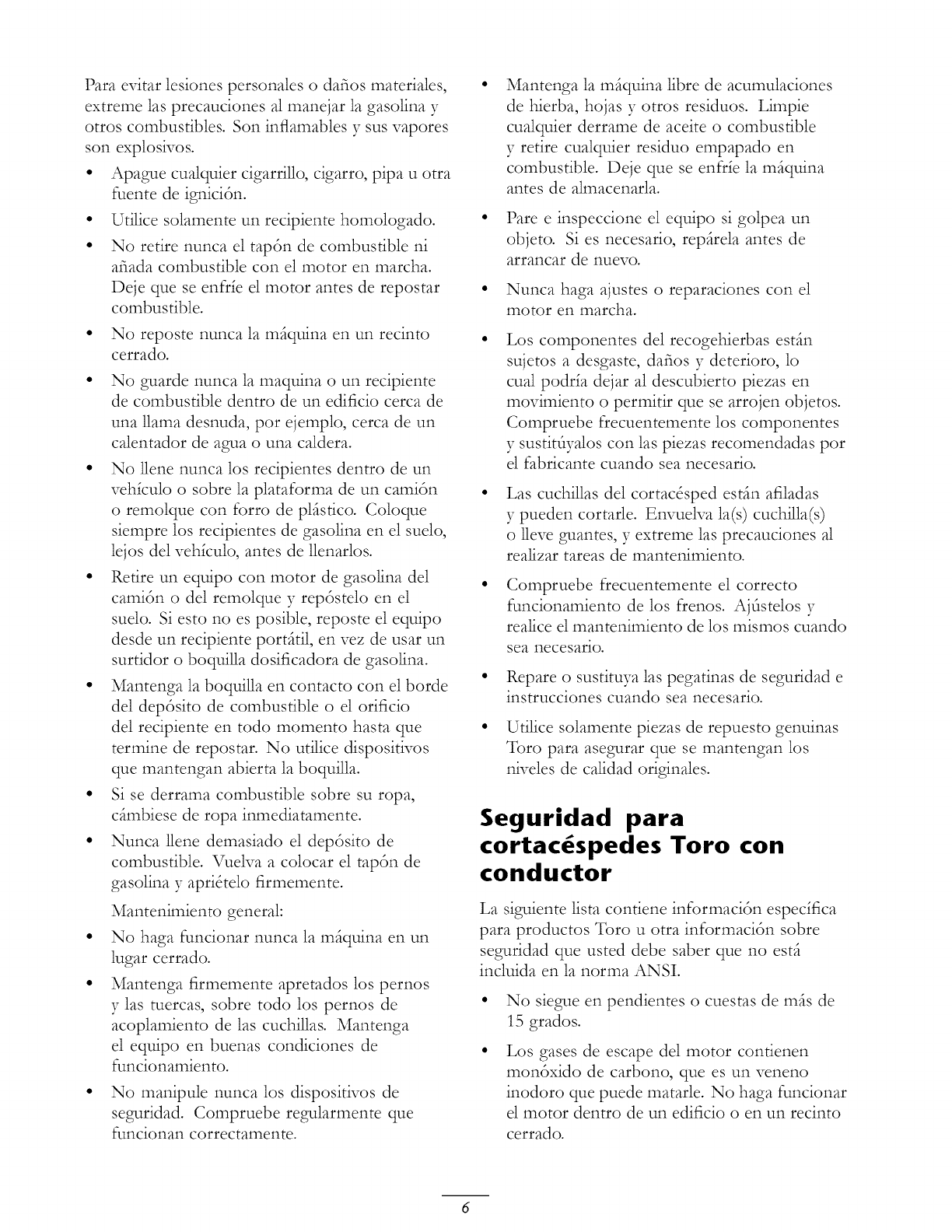
Para evitar lesiones personales o dafios materiales,
extreme las precauciones al manejar la gasolina y
otros combustibles. Son inflamables y sus vapores
son explosNos.
• Apague cualquier cigarrillo, cigarro, pipa u otra
fuente de ignici6n.
• Utilice solamente un recipiente homologado.
• No retire nunca el tap6n de combustible ni
afiada combustible con el motor en marcha.
Deje que se enfde el motor antes de repostar
combustible.
• No reposte nunca la mfiquina en un recinto
cerrado.
• No guarde nunca la maquina o un recipiente
de combustible dentro de un edificio cerca de
una llama desnuda, pot ejemplo, cerca de un
calentador de agua o una caldera.
• No 11enenunca los recipientes dentro de un
vehiculo o sobre la plataforma de un camidn
o remolque con forro de plfistico. Coloque
siempre los recipientes de gasolina en el suelo,
lejos del vehiculo, antes de llenarlos.
• Retire un equipo con motor de gasolina de1
camidn o del remolque y repdstelo en el
suelo. Si esto no es posible, reposte el equipo
desde un recipiente portfitil, en vez de usar un
surtidor o boquilla dosificadora de gasolina.
• Mantenga la boquilla en contacto con el horde
del depdsito de combustible o el orificio
del recipiente en todo momento hasta que
termine de repostar. No utilice dispositivos
que mantengan abierta la boquilla.
• Si se derrama combustible sobre su ropa,
cfimbiese de ropa inmediatamente.
• Nunca 11ene demasiado el depdsito de
combustible. Vuelva a colocar el tapdn de
gasolina y apri&elo firmemente.
Mantenimiento general:
No haga funcionar nunca la mfiquina en un
lugar cerrado.
Mantenga firmemente apretados los pernos
y las tuercas, sobre todo los pernos de
acoplamiento de las cuchillas. Mantenga
el equipo en buenas condiciones de
funcionamiento.
• No manipule nunca los dispositivos de
seguridad. Compruebe regularmente que
funcionan correctamente.
Mantenga la mfiquina libre de acumulaciones
de hierba, hojas y otros residuos. Limpie
cualquier derrame de aceite o combustible
y retire cualquier residuo empapado en
combustible. Deje que se enfde la mfiquina
antes de almacenarla.
Pare e inspeccione el equipo si golpea un
objeto. Si es necesario, repfirela antes de
arrancar de nuevo.
Nunca haga ajustes o reparaciones con el
motor en marcha.
Los componentes del recogehierbas est,'in
sujetos a desgaste, dafios y deterioro, lo
cual podda dejar al descubierto piezas en
movimiento o permitir que se arrojen objetos.
Compruebe frecuentemente los componentes
y sustittlyalos con las piezas recomendadas por
el fabricante cuando sea necesario.
Las cuchillas del cortac&ped estfin afiladas
y pueden cortarle. Envuelva la(s) cuchilla(s)
o lleve guantes, y extreme las precauciones al
realizar tareas de mantenimiento.
Compruebe frecuentemente el correcto
funcionamiento de los ffenos. Ajtlstelos y
realice el mantenimiento de los mismos cuando
sea necesario.
Repare o sustituya las pegatinas de seguridad e
instrucciones cuando sea necesario.
Utilice solamente piezas de repuesto genuinas
Toro para asegurar que se mantengan los
niveles de calidad originales.
Seguridad para
cortac spedes Toro con
conductor
La siguiente lista contiene informaci6n espec_fica
para productos Toro u otra informaci6n sobre
seguridad que usted debe saber que no estfi
incluida en la norma ANSI.
No siegue en pendientes o cuestas de mils de
15 grados.
Los gases de escape del motor contienen
mondxido de carbono, que es un veneno
inodoro que puede matarle. No haga funcionar
el motor dentro de un edificio o en un recinto
cerrado.
Pareel motor, desconectelos cablesdelas
buj_asy retirelallaveantesderealizarcualquier
revisi6n,reparaci6n,mantenimientoo ajuste.
Cuandoelmotorest_enmarcha,mantengalas
manos,lospies,elpeloy laropasueltaalejados
delazonadedescargadelosaccesorios,
losbajosdelcortac&pedy laspiezasen
movimiento.
No toqueningfinequipoo piezaquepueda
estarcalientedebidoala operacidn.Dejeque
seenfr_enantesderealizarcualquieroperaci6n
demantenimiento,ajusteo revisi6n.
E1ficidodelabaterlaesvenenosoy puede
causarquemaduras.Eviteel contactoconla
pie1,los ojosy laropa. Prot_jasela cara,los
ojosy laropacuandotrabajeconunabater_a.
Losgasesdela bater_apuedenexplotar.
Mantengaalejadosdela bater_acigarrillos,
chispasy llamas.
Utilicesolamenteaccesorioshomologadospor
Toro. La garanda puede quedar anulada si se
utilizan accesorios no autorizados.
Para cargar la mfiquina en un remolque o
cami6n, utilice finicamente una sola rampa de
ancho completo. E1 fingulo de la rampa no
debe superar los 15 grados.
Nora: Los lados derecho e izquierdo de
la mfiquina se determinan desde la posicidn
normal del operador.
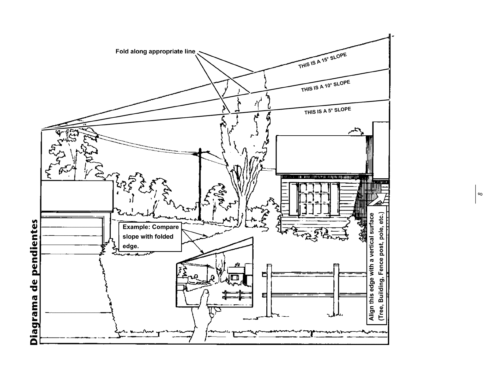
Q;
"0
Q;
s_
Fold along appropriate line
Example: Compare
slope with folded
edge.
!1
\
SLOPE
THIS IS A 5° SLOPE
/
=
I_ I
€l
oo
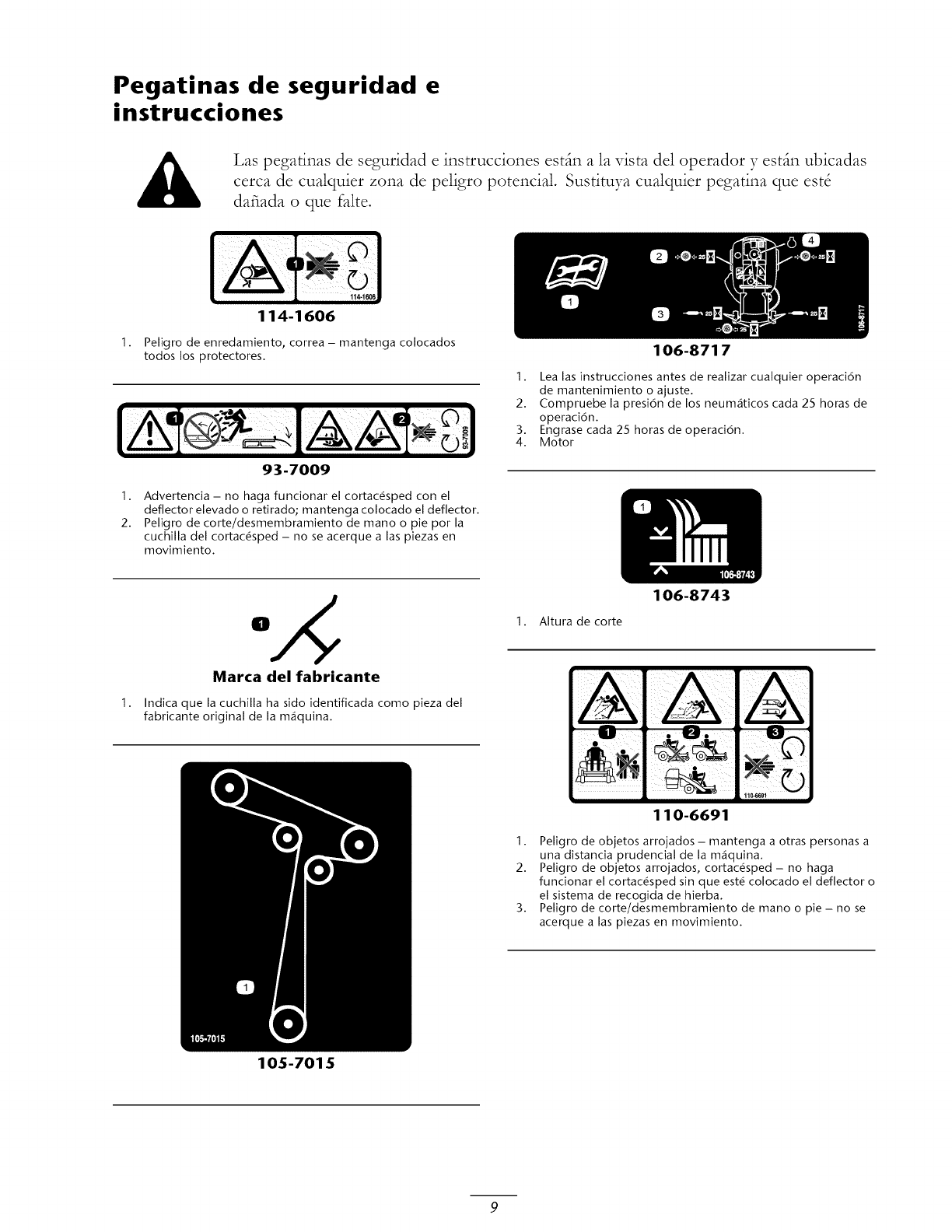
Pegatinas de seguridad e
instrucciones
I.
Las pegatinas de seguridad e instrucciones estfin a la vista del operador y estfin ubicadas
cerca de cualquier zona de peligro potencial. Sustituya cualquier pegatina que est8
dafiada o que falte.
114-1606
114-1606
Peligro de enredamiento, correa - mantenga colocados
todos los protectores.
93-7009
106-8717
1. Lea las instrucciones antes de realizar cualquier operaci6n
de mantenimiento o aiuste.
2. Compruebe la presi6n de los neum_ticos cada 25 horas de
operaci6n.
3. Engrase cada 25 horas de operaci6n.
4. Motor
1. Advertencia - no haga funcionar el cortac#sped con el
deflector elevado o retirado; mantenga colocado el deflector.
2. Peligro de corte/desmembramiento de mano o pie por la
cuchilla del cortac#sped - no se acerque alas piezas en
movimiento.
1.
Marca del fabricante
Indica que la cuchilla ha sido identificada como pieza del
fabricante original de la maquina.
105-7015
I. Altura de corte
106-8743
110-6691
I. Peligro de objetos arroiados - mantenga a otras personas a
una distancia prudencial de la m_quina.
2. Peligro de obietos arroiados , cortac@sped - no haga
funcionar el cortac@sped sin que est@ colocado el deflector o
el sistema de recogida de hierba.
3. Peligro de corte/desmembramiento de mano o pie - no se
acerque alas piezas en movimiento.
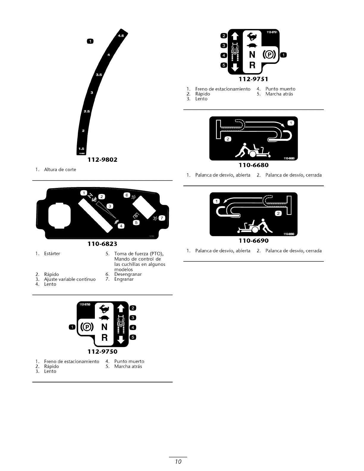
0
0
0
0
112-9751
1. Freno deestacionamiento 4. Punto muerto
2. R4pido 5. Marcha atr4s
3. Lento
1. Altura de corte
112-9802
110-6823
110-6680
1. Palanca de desv[o, abierta 2. Palanca de desv[o, cerrada
1. Est4rter
2. R_ipido
3. Ajuste variable continuo
4. Lento
5. Toma de fuerza (PTO),
Mando de control de
las cuchillas en algunos
modelos
6. Desengranar
7. Engranar
110-6690
1. Palanca de desv[o, abierta 2. Palanca de desv[o, cerrada
O(Q) N
0
0
0
0
112-9750
1. Frenodeestacionamiento 4. Punto muerto
2. R_ipido 5. Marcha atr_is
3. Lento
10
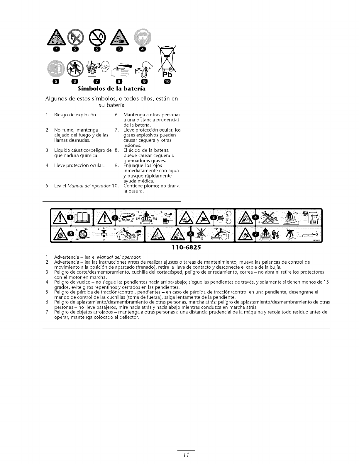
0 0 0 0 0
0 0 0
Simbolos de la bateria
0 0 Q
Algunos de estos s_mbolos, o todos ellos, est_n en
su bateffa
1. Riesgo de explosi6n 6.
2. No fume, mantenga 7.
alejado del fuego yde las
llamas desnudas.
3. L[quido c_ustico/peligro de 8.
quemadura qu[mica
4. Lleve protecci6n ocular. 9.
5. Lea el Manual del operador.10.
Mantenga a otras personas
a una distancia prudencial
de la bater[a.
Lleve protecci6n ocular; los
gases explosivos pueden
causar ceguera yotras
lesiones.
El _cido de la bateffa
puede causar ceguera o
quemaduras graves.
Enjuague los ojos
inmediatamente con agua
y busque r_pidamente
ayuda m_dica.
Contiene plomo; no tirar a
la basura.
110-6825
1. Advertencia - lea el Manual del operador.
2. Advertencia - lea las instrucciones antes de realizar ajustes o tareas de mantenimiento; mueva las palancas de control de
movimiento a la posici6n de aparcado (frenado), retire la Ilave de contacto ydesconecte el cable de la buj[a.
3. Peligro de corte/desmembramiento, cuchilla del cortac#sped; peligro de enredamiento, correa - no abra ni retire los protectores
con el motor en marcha.
4. Peligro de vuelco - no siegue las pendientes hacia arriba/abajo; siegue las pendientes de trav#s, ysolamente si tienen menos de 1 5
grados, evite giros repentinos ycerrados en las pendientes.
5. Peligro de p#rdida de tracci6n/control, pendientes - en caso de p#rdida de tracci6n/control en una pendiente, desengrane el
mando de control de las cuchillas (toma de fuerza), salga lentamente de la pendiente.
6. Peligro de aplastamiento/desmembramiento de otras personas, marcha arras; peligro de aplastamiento/desmembramiento de otras
personas - no Ileve pasajeros, mire hacia atr_s y hacia abajo mientras conduzca en marcha arras.
7. Peligro de objetos arrojados - mantenga a otras personas a una distancia prudencial de la m_quina y recoja todo residuo antes de
operar; mantenga colocado el deflector.
11
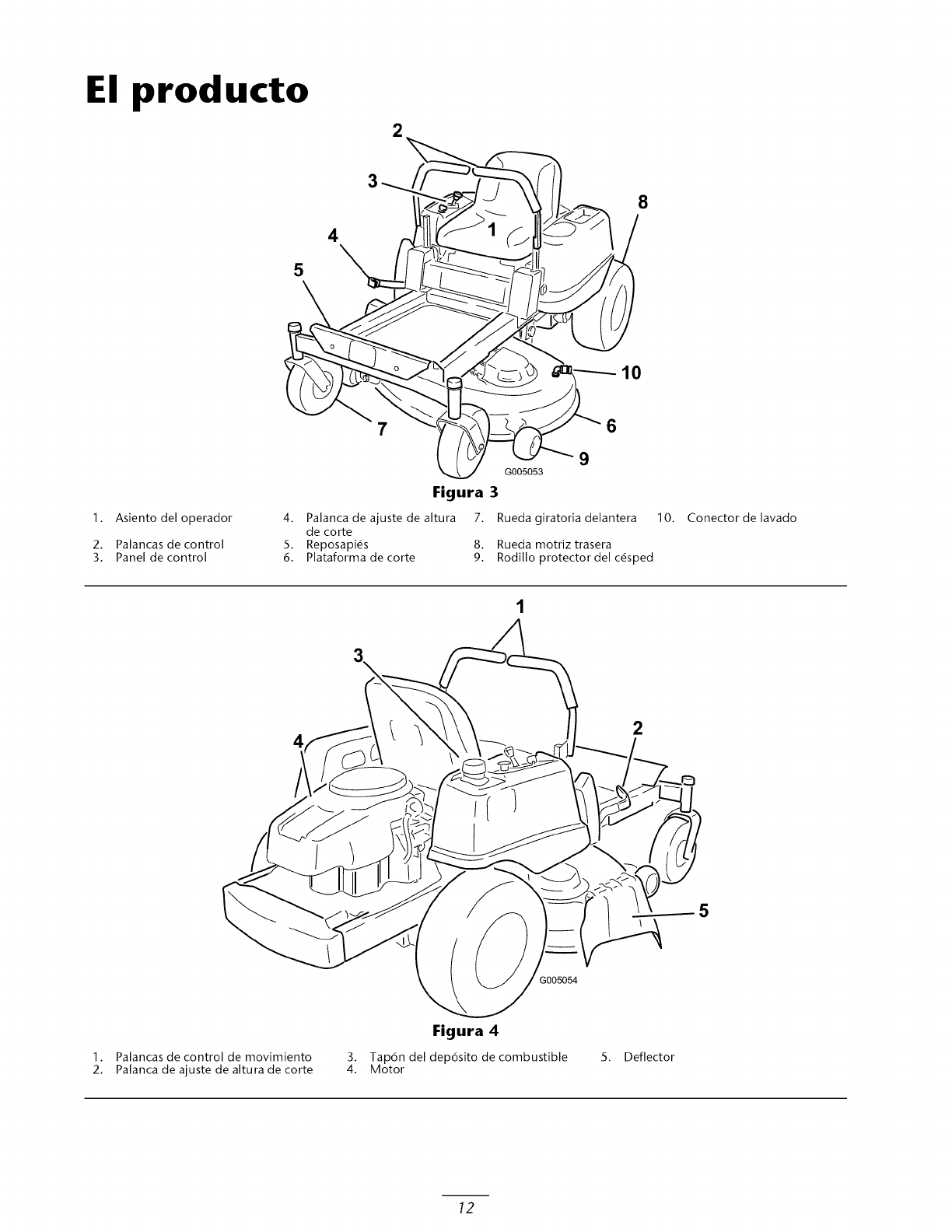
El producto
2
5
4
8
10
1. Asiento del operador
2. Palancas de control
3. Panel de control
9
G005053
Figura 3
4. Palanca de ajuste de altura
de corte
5. Reposapi#s
6. Plataforma de corte
7. Rueda giratoria delantera
8. Rueda motriz trasera
9. Rodillo protector del c_sped
10. Conector de lavado
2
1. Palancas de control de movimiento
2. Palanca de ajuste de altura de corte
Figura 4
3. Tap6n del dep6sito de combustible
4. Motor 5. Deflector
12
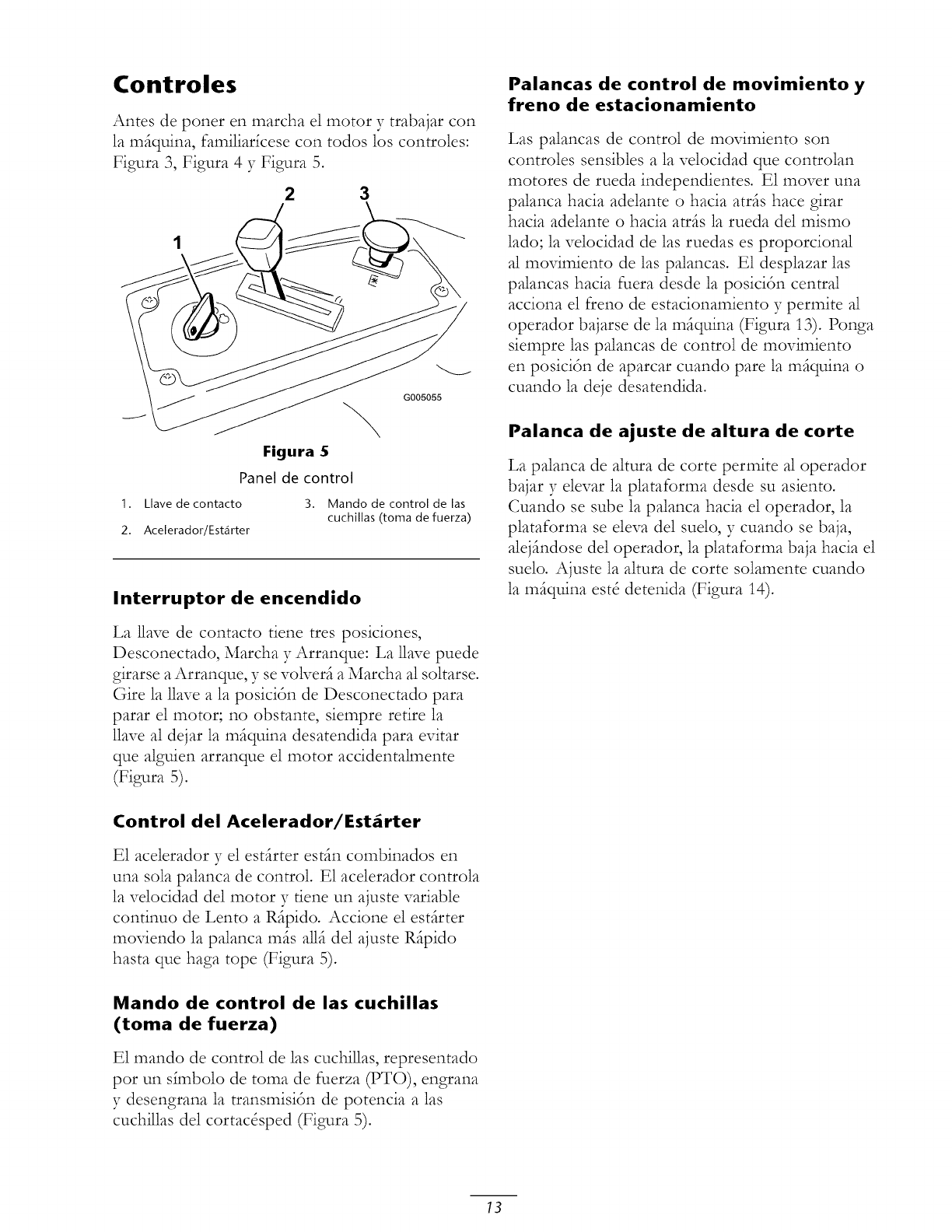
Controles
Antes de poner en marcha el motor y trabajar con
la mfiquina, familiar_cese con todos los controles:
Figura 3, Figura 4 y Figura 5.
23
Figura 5
Panel de control
G005055
1. Llave de contacto
2. Acelerador/Estarter
3. Mando de control de las
cuchillas (toma de fuerza)
Interruptor de encendido
La llave de contacto tiene tres posiciones,
Desconectado, Marcha y Arranque: La 1lave puede
girarse a Arranque, y se volverfi a Marcha al soltarse.
Gire la llave a la posicidn de Desconectado para
parar el motor; no obstante, siempre retire la
llave al dejar la mfiquina desatendida para evitar
que alguien arranque el motor accidentalmente
(Figura 5).
Control del Acelerador/Est_rter
E1 acelerador y el estfirter estfin combinados en
una sola palanca de control. E1 acelerador controla
la velocidad del motor y tiene un ajuste variable
continuo de Lento a Rfipido. Accione el estfirter
moviendo la palanca mils a11ide1 ajuste Ripido
hasta que haga tope (Figura 5).
Mando de control de las cuchillas
(toma de fuerza)
E1 mando de control de las cuchillas, representado
pot un s_mbolo de toma de fuerza (PTO), engrana
y desengrana la transmisidn de potencia alas
cuchillas de1 cortac&ped (Figura 5).
Palancas de control de movimiento y
freno de estacionamiento
Las palancas de control de movimiento son
controles sensibles a la velocidad que controlan
motores de rueda independientes. E1 mover una
palanca hacia adelante o hacia atris hace girar
hacia adelante o hacia atris la rueda de1 mismo
lado; la velocidad de las ruedas es proporcional
al movimiento de las palancas. E1 desplazar las
palancas hacia fuera desde la posicidn central
acciona el freno de estacionamiento y permite al
operador bajarse de la miquina (Figura 13). Ponga
siempre las palancas de control de movimiento
en posicidn de aparcar cuando pare la miquina o
cuando la deje desatendida.
Palanca de ajuste de altura de corte
La palanca de altura de corte permite al operador
bajar y elevar la plataforma desde su asiento.
Cuando se sube la palanca hacia el operador, la
plataforma se eleva del suelo, y cuando se baja,
alejindose de1 operador, la plataforma baja hacia el
suelo. Ajuste la altura de corte solamente cuando
la miquina est8 detenida (Figura 14).
13
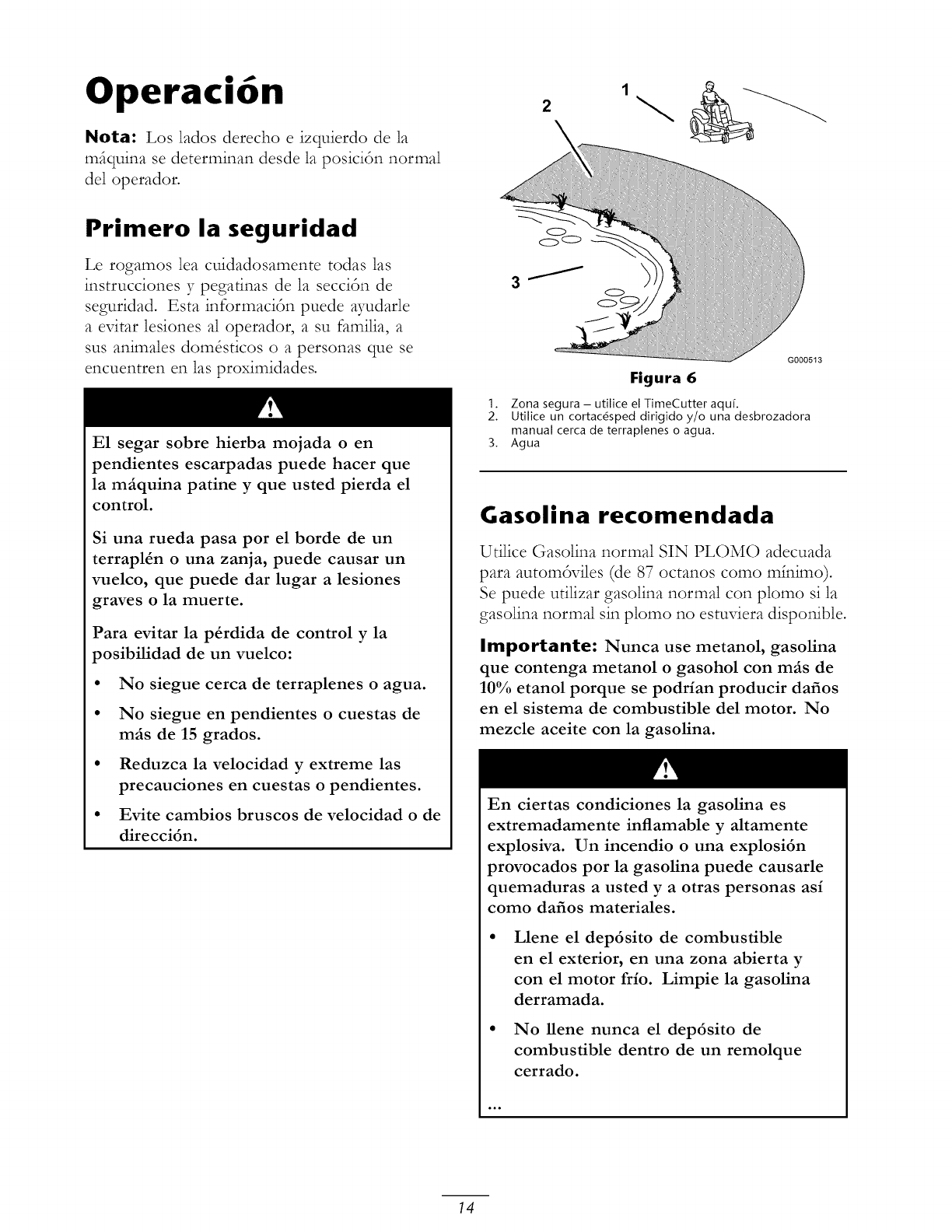
Operaci6n
Nota: Los lados derecho e izquierdo de la
mfiquina se determinan desde la posiciSn normal
del operador.
2
Primero la seguridad
Le rogamos lea cuidadosamente todas hs
instrucciones y pegafinas de la secciSn de
seguridad. Esta informaci6n puede ayudarle
aevitar lesiones al operador, asu familia, a
sus animales domOsticos o a personas que se
encuentren en las proximidades.
E1 segar sobre hierba mojada oen
pendientes escarpadas puede hacer que
la m_quina patine y que usted pierda el
control.
Si una rueda pasa pot el borde de un
terrapl4n ouna zanja, puede causar un
vuelco, que puede dar lugar a lesiones
graves o la muerte.
Para evitar la p4rdida de control yla
posibilidad de un vuelco:
• No siegue cerca de terraplenes o agua.
• No siegue en pendientes o cuestas de
m_s de 15 grados.
• Reduzca la velocidad y extreme las
precauciones en cuestas o pendientes.
• Evite cambios bruscos de velocidad o de
direcci6n.
G000513
Figura 6
1. Zona segura - utilice el TimeCutter aquL
2. Utilice un cortacdsped dirigido y/o una desbrozadora
manual cerca de terraplenes o agua.
3. Agua
Gasolina recomendada
Utilice Gasolina normal SIN PLOMO adecuada
para autom6viles (de 87 octanos como mh_imo).
Se puede utilizar gasolina normal con plomo si la
gasolina normal sin plomo no estuviera dispoicible.
Importante: Nunca use metanol, gasolina
que contenga metanol o gasohol con m_s de
10% etanol porque se podrian producir dafios
en el sistema de combustible del motor. No
mezcle aceite con la gasolina.
En ciertas condiciones la gasolina es
extremadamente inflamable y altamente
explosiva. Un incendio o una explosi6n
provocados pot la gasolina puede causarle
quemaduras a usted y a otras personas as/
como dafios materiales.
Llene el dep6sito de combustible
en el exterior, en una zona abierta y
con el motor frio. Limpie la gasolina
derramada.
• No llene nunca el dep6sito de
combustible dentro de un remolque
cerrado.
14
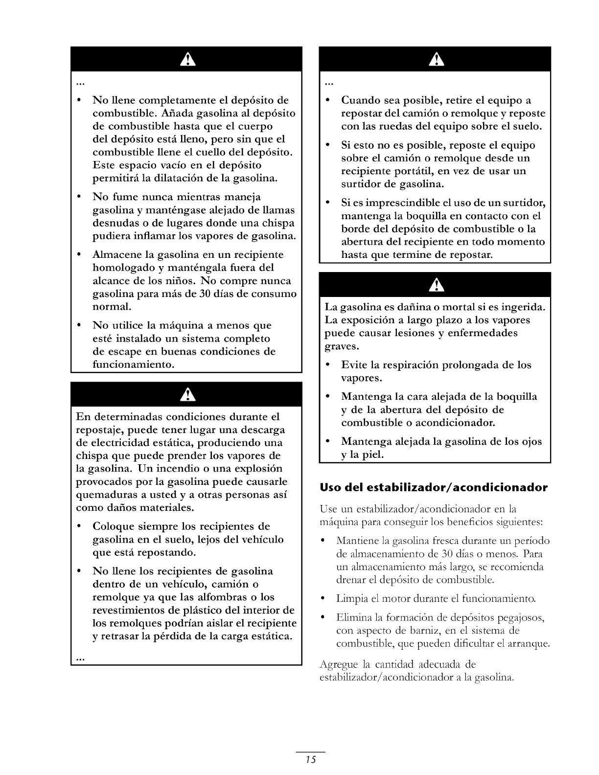
No llene completamente el dep6sito de
combustible. Afiada gasolina al dep6sito
de combustible hasta que el cuerpo
del dep6sito est_ lleno, pero sin que el
combustible llene el cuello del dep6sito.
Este espacio vacio en el dep6sito
permitir_ la dilataci6n de la gasolina.
No fume nunca mientras maneja
gasolina y mant_ngase alejado de llamas
desnudas o de lugares donde una chispa
pudiera inflamar los vapores de gasolina.
Almacene la gasolina en un recipiente
homologado y mant_ngala fuera del
alcance de los nifios. No compre nunca
gasolina para m_s de 30 dias de consumo
normal.
No utilice la m_quina a menos que
est4 instalado un sistema completo
de escape en buenas condiciones de
funcionamiento.
En determinadas condiciones durante el
repostaje, puede tener lugar una descarga
de electricidad est_tica, produciendo una
chispa que puede prender los vapores de
la gasolina. Un incendio o una explosi6n
provocados por la gasolina puede causarle
quemaduras a usted y a otras personas as/
como dafios materiales.
Coloque siempre los recipientes de
gasolina en el suelo, lejos del vehiculo
que est_ repostando.
No llene los recipientes de gasolina
dentro de un vehiculo, cami6n o
remolque ya que las alfombras o los
revestimientos de pkistico del interior de
los remolques podHan aislar el recipiente
y retrasar la p_rdida de la carga est_tica.
Cuando sea posible, retire el equipo a
repostar del cami6n o remolque y reposte
con las ruedas del equipo sobre el suelo.
Si esto no es posible, reposte el equipo
sobre el cami6n o remolque desde un
recipiente port_til, en vez de usar un
surtidor de gasolina.
Si es imprescindible el uso de un surtidor,
mantenga la boquilla en contacto con el
borde del dep6sito de combustible o la
abertura del recipiente en todo momento
hasta que termine de repostar.
La gasolina es dafiina o mortal si es ingerida.
La exposici6n a largo plazo a los vapores
puede causar lesiones y enfermedades
graves.
• Evite la respiraci6n prolongada de los
vapores.
• Mantenga la cara alejada de la boquilla
y de la abertura del dep6sito de
combustible o acondicionador.
• Mantenga alejada la gasolina de los ojos
y la piel.
Uso del estabilizador/acondicionador
Use un estabilizador/acondicionador en la
mfiquina para conseguir los beneficios siguientes:
Mantiene la gasolina fresca durante un perlodo
de almacenamiento de 30 dlas o menos. Para
un almacenamiento mils largo, se recomienda
drenar el dep6sito de combustible.
Limpia el motor durante el funcionamiento.
Elimina la formaci6n de dep6sitos pegajosos,
con aspecto de bamiz, en el sistema de
combustible, que pueden dificultar el arranque.
Agregue la cantidad adecuada de
estabilizador/acondicionador a la gasolina.
15
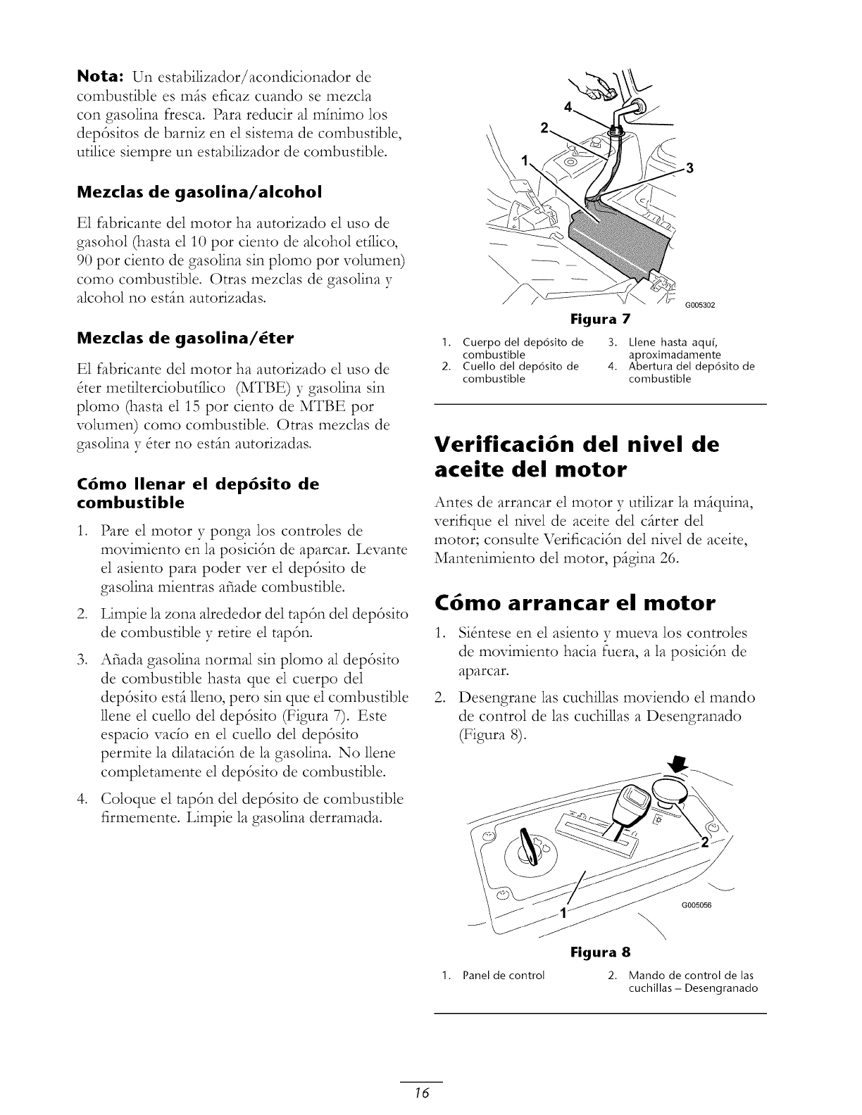
Nora: Un estabilizador/acondicionador de
combustible es mils eficaz cuando se mezcla
con gasolina fresca. Para reducir al mh_imo los
depdsitos de bari-fiz en el sistema de combustible,
utilice siempre un estabilizador de combustible.
Mezclas de gasolina/alcohol
E1 fabricante del motor ha autorizado el uso de
gasohol (hasta el 10 por ciento de alcohol etflico,
90 por ciento de gasolina sin plomo por volumen)
como combustible. Otras mezclas de gasolina y
alcohol no estin autorizadas.
Mezclas de gasolina/6ter
E1 fabricante del motor ha autorizado el uso de
&er metilterciobutilico (MTBE) y gasolina sin
plomo (hasta el 15 por ciento de MTBE por
volumen) como combustible. Otras mezclas de
gasolina y &er no estin autorizadas.
C6mo Ilenar el dep6sito de
combustible
,
,
,
,
Pare el motor y ponga los controles de
movimiento en la posicidn de aparcar. Levante
el asiento para poder ver el deptsito de
gasolina mientras afiade combustible.
Limpie la zona alrededor del taptn del deptsito
de combustible 37retire el taptn.
Afiada gasolina normal sin plomo al deptsito
de combustible hasta que el cuerpo de1
deptsito estil 11eno,pero sin que el combustible
llene el cuello de1 deptsito (Figura 7). Este
espacio vado en el cuello del deptsito
permite la dilatacitn de la gasolina. No llene
completamente el deptsito de combustible.
Coloque el taptn del deptsito de combustible
firmemente. Limpie la gasolina derramada.
G005302
Figura 7
1. Cuerpo del dep6sito de 3. Llene hasta aqu[,
combustible aproximadamente
2. Cuello del dep6sito de 4. Abertura del dep6sito de
combustible combustible
Verificaci6n del nivel de
aceite del motor
Antes de arrancar el motor y utilizar la miquina,
verifique el nivel de aceite del cilrter del
motor; consulte Verificaci6n del nivel de aceite,
Mantenimiento del motor, pigina 26.
C6mo arrancar el motor
,
,
Si&_tese en el asiento y mueva los controles
de movimiento hacia fuera, a la posicitn de
aparcar.
Desengrane las cuchillas moviendo el mando
de control de las cuchillas a Desengranado
(Figura 8).
1. Panel de control
G005056
Figura 8
2. Mando de control de las
cuchillas - Desengranado
16
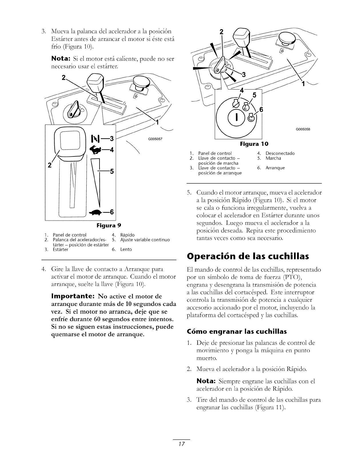
,
Mueva la palanca del acelerador a la posici6n
Estfirter antes de arrancar el motor si _ste estfi
frfo (Figura 10).
Nora: Si el motor estfi caliente, puede no set
necesario usar el estfirter.
,,gD-m6
G005057
Figura 9
I. Panel de control 4. Rapido
2. Palanca del acelerador/es- 5. Ajuste variable continuo
tarter - posici6n de estarter
3. Estarter 6. Lento
Gire la llave de contacto a Arranque para
activar el motor de arranque. Cuando el motor
arranque, suelte la llave (Figura 10).
Importante: No active el motor de
arranque durante mils de 10 segundos cada
vez. Si el motor no arranca, deje que se
enfrie durante 60 segundos entre intentos.
Si no se siguen estas instrucciones, puede
quemarse el motor de arranque.
G005058
Figura 10
1. Panel de control 4. Desconectado
2. klave de contacto - 5. Marcha
posici6n de marcha
3. Llave de contacto - 6. Arranque
posici6n de arranque
Cuando el motor arranque, mueva el acelerador
a la posici6n Rfipido (Figura 10). Si el motor
se cala o funciona irregularmente, vuelva a
colocar el acelerador en Estfirter durante unos
segundos. Luego mueva el acelerador a la
posici6n deseada. Repita este procedimiento
tantas veces como sea necesario.
Operaci6n de las cuchillas
E1 mando de control de las cuchillas, representado
pot un sfmbolo de toma de fuerza (PTO),
engrana y desengrana la transmisi6n de potencia
alas cuchillas del cortac&ped. Este interruptor
controla la transmisi6n de potencia a cualquier
accesorio accionado por el motor, inclwendo la
plataforma del cortac&ped y las cuchillas.
C6mo engranar las cuchillas
1. Deje de presionar las palancas de control de
movimiento y ponga la mfiquina en punto
muerto.
2. Mueva el acelerador a la posici6n Rfipido.
,
Nota: Siempre engrane las cuchillas con el
acelerador en la posici6n de Rfipido.
Tire del mando de control de las cuchillas para
engranar las cuchillas (Figura 11).
17
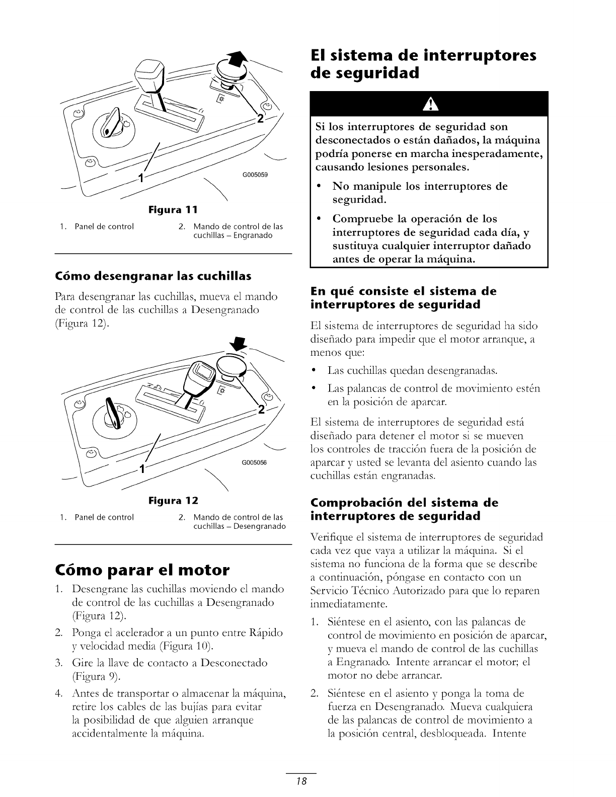
El sistema de interruptores
de seguridad
G005059
Figura 1 1
1. Panel de control 2. Mando de control de las
cuchillas -Engranado
C6mo desengranar las cuchillas
Para desengranar las cuchillas, mueva el mando
de control de las cuchillas a Desengranado
(Figura 12).
1. Panel de control
G005056
Figura 12
2. Mando de control de las
cuchillas - Desengranado
C6mo parar el motor
1. Desengrane las cuchillas moviendo el mando
de control de las cuchillas a Desengranado
(Figura 12).
2. Ponga el acelerador a un punto entre Rfipido
y velocidad media (Figura 10).
3. (;ire la 1lave de contacto a Desconectado
(Figura 9).
4. Antes de transportar o almacenar la mfiquina,
retire los cables de las buj_as para evitar
la posibilidad de que alguien arranque
accidentalmente la mfiquina.
Si los interruptores de seguridad son
desconectados o est_n dafiados, la m_quina
podria ponerse en marcha inesperadamente,
causando lesiones personales.
• No manipule los interruptores de
seguridad.
Compruebe la operaci6n de los
interruptores de seguridad cada dia, y
sustituya cualquier interruptor dafiado
antes de operar la m_iquina.
En qu_ consiste el sistema de
interruptores de seguridad
E1 sistema de interruptores de seguridad ha sido
disefiado para impedir que el motor arranque, a
menos qLle:
•Las cuchillas quedan desengranadas.
•Las palancas de control de movimiento est_n
en la posici6n de aparcar.
E1 sistema de interruptores de seguridad est_
disefiado para detener el motor si se mueven
los controles de tracci6n fuera de la posici6n de
aparcar y usted se levanta del asiento cuando las
cuchillas est_n engranadas.
Comprobaci6n del sistema de
interruptores de seguridad
Verifique el sistema de interruptores de seguridad
cada vez que vaya a ufilizar la mfiquina. Si el
sistema no funciona de la forma que se describe
a continuaci6n, p6ngase en contacto con un
Servicio T&nico Autorizado para que lo reparen
inmediatamente.
,Si_ntese en el asiento, con 1as palancas de
control de movimiento en posici6n de aparcar,
y mueva el mando de control de las cuchillas
a Engranado. Intente arrancar el motor; el
motor no debe arrancar.
,SiSntese en el asiento y ponga la toma de
fuerza en Desengranado. Mueva cualquiera
de las palancas de control de movimiento a
la posici6n central, desbloqueada. Intente
18
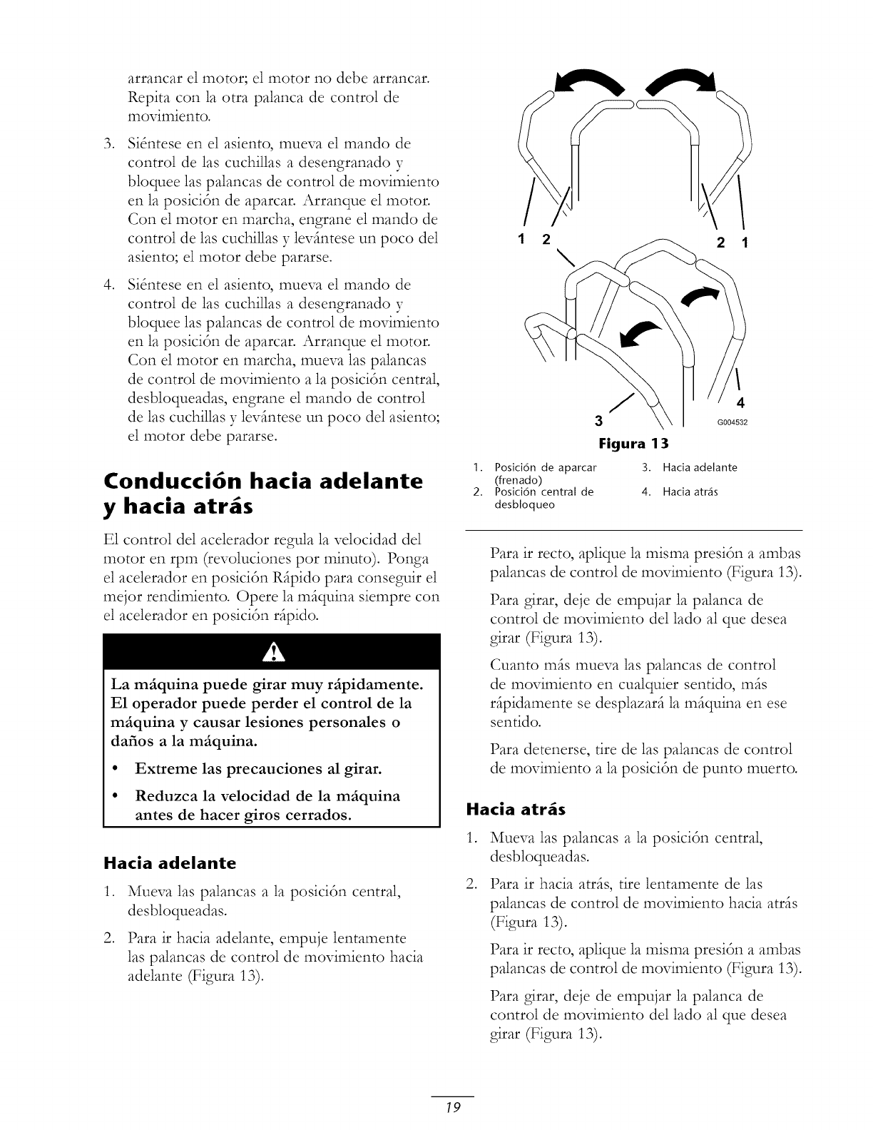
,
,
arrancar el motor; el motor no debe arrancar.
Repita con la otra palanca de control de
movimiento.
Si_ntese en el asiento, mueva el mando de
control de las cuchillas a desengranado y
bloquee las palancas de control de movimiento
en la posici6n de aparcar. Arranque el motor.
Con el motor en marcha, engrane el mando de
control de 1as cuchillas y levfintese un poco del
asiento; el motor debe pararse.
Si_ntese en el asiento, mueva el mando de
control de las cuchillas a desengranado y
bloquee las palancas de control de movimiento
en la posici6n de aparcar. Arranque el motor.
Con el motor en marcha, mueva las palancas
de control de movimiento a la posici6n central,
desbloqueadas, engrane el mando de control
de 1as cuchillas y levfintese un poco del asiento;
el motor debe pararse.
Conducci6n hacia adelante
y hacia atr s
E1 control de1 acelerador regula la velocidad de1
motor en rpm (revoluciones por minuto). Ponga
el acelerador en posici6n Rfipido para conseguir el
mejor rendimiento. Opere la mfiquina siempre con
el acelerador en posici6n rfipido.
La m_iquina puede girar muy r_ipidamente.
E1 operador puede perder el control de la
m_iquina y causar lesiones personales o
dafios a la m_iquina.
• Extreme las precauciones al girar.
• Reduzca la velocidad de la m_iquina
antes de hacer giros cerrados.
Hacia adelante
,
,
Mueva las palancas a la posici6n central,
desbloqueadas.
Para ir hacia adelante, empuje lentamente
las palancas de control de movimiento hacia
adelante (Figura 13).
1 2 2 1
J4
G004532
Figura 13
1. Posici6n de aparcar 3. Hacia adelante
(frenado)
2. Posici6n central de 4. Hacia arras
desbloqueo
Para ir recto, aplique la misma presi6n a ambas
palancas de control de movimiento (Figura 13).
Para girar, deje de empujar la palanca de
control de movimiento del lado al que desea
girar (Figura 13).
Cuanto mils mueva 1as palancas de control
de movimiento en cualquier sentido, mils
ripidamente se desplazari la mfiquina en ese
sentido.
Para detenerse, tire de 1as palancas de control
de movimiento a la posici6n de punto muerto.
Hacia atr_s
,
,
Mueva las palancas a la posici6n central,
desbloqueadas.
Para ir hacia atrfis, tire lentamente de las
palancas de control de movimiento hacia atrfis
(Figura 13).
Para ir recto, aplique la misma presi6n a ambas
palancas de control de movimiento (Figura 13).
Para girar, deje de empujar la palanca de
control de movimiento del lado al que desea
girar (Figura 13).
19
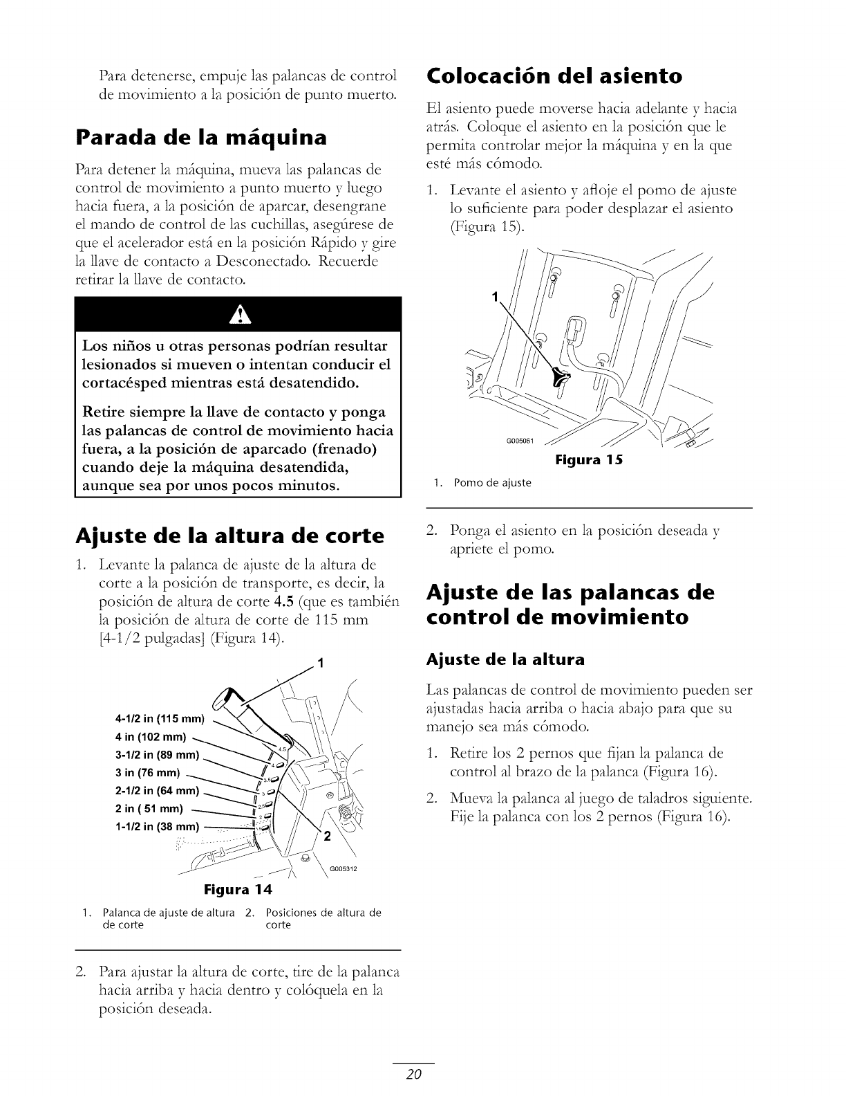
Para detenerse, empuje las palancas de control
de movimiento a la posicitn de punto muerto.
Parada de la m quina
Para detener la mfiquina, mueva las palancas de
control de movimiento a punto muerto y luego
hacia fuera, a la posicidn de aparcar, desengrane
el mando de control de las cuchillas, aseg_rese de
que el acelerador estfi en la posicidn Rfipido y gire
la llave de contacto a Desconectado. Recuerde
retirar la 1lave de contacto.
Los nifios u otras personas podrian resultar
lesionados si mueven o intentan conducir el
cortac_sped mientras estfi desatendido.
Retire siempre la nave de contacto y ponga
las palancas de control de movimiento hacia
fuera, a la posici6n de aparcado (frenado)
cuando deje la mfiquina desatendida,
aunque sea por unos pocos minutos.
Colocaci6n del asiento
E1 asiento puede moverse hacia adelante y hacia
atris. Coloque el asiento en la posici6n que le
permita controlar mejor la miquina y en la que
est8 mils ctmodo.
1. Levante el asiento y afloje el pomo de ajuste
lo suficiente para poder desplazar el asiento
(Figura 15).
1. Pomo de ajuste
Figura 15
Ajuste de la altura de corte
1. Levante la palanca de ajuste de la altura de
corte a la posicitn de transporte, es decir, la
posicitn de altura de corte 4.5 (que es tambiSn
la posicitn de altura de corte de 115 mm
[4-1/2 pulgadas] (Figura 14).
4-1/2 in (115 mm)
4 in (102 mm)
3-1/2 in (89 mm)
3 in (76 mm)
2-1/2 in (64 mm)
2 in ( 51 mm)
1-1/2 in (38 mm) --
2. Ponga el asiento en la posicitn deseada y
apriete el pomo.
Ajuste de las palancas de
control de movimiento
Ajuste de la altura
Las palancas de control de movimiento pueden ser
ajustadas hacia arriba o hacia abajo para que su
manejo sea mils ctmodo.
,
,
Retire los 2 pernos que fijan la palanca de
control al brazo de la palanca (Figura 16).
Mueva la palanca al juego de taladros siguiente.
Fije la palanca con los 2 pernos (Figura 16).
1.
Figura 14
Palanca de ajuste de altura 2. Posiciones de altura de
de corte corte
2. Para ajustar la altura de corte, fire de la palanca
hacia arriba 37hacia dentro y coltquela en la
posicitn deseada.
20
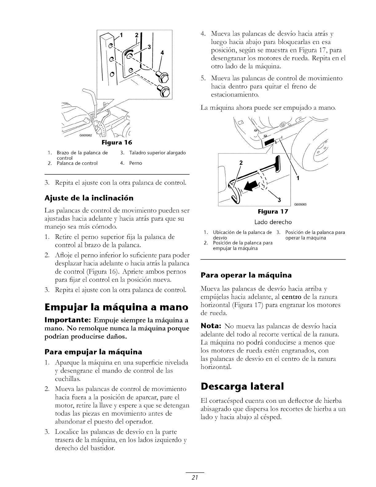
\
Figura 16
1. Brazo de la palanca de 3. Taladro superior alargado
control
2. Palanca de control 4. Perno
3. Repita el ajuste con la otra palanca de control.
Ajuste de la inclinaci6n
Las palancas de control de movimiento pueden ser
ajustadas hacia adelante y hacia atrfis para que su
manejo sea mils cdmodo.
1. Retire el perno superior fija la palanca de
control al brazo de la palanca.
2. Afloje el perno inferior lo suficiente para poder
desplazar hacia adelante o hacia atrfis la palanca
de control (Figura 16). Apriete ambos pernos
para fijar el control en la posicidn nueva.
3. Repita el ajuste con la otra palanca de control•
Empujar la m quina a mano
Importante: Empuje siempre la m_iquina a
mano. No remolque nunca la m_iquina porque
podrfan producirse dafios.
Para empujar la m_quina
1. Aparque la mfiquina en una superficie nivelada
y desengrane el mando de control de las
cuchillas.
2. Mueva las palancas de control de movimiento
hacia fuera a la posicidn de aparcar, pare el
motor, retire la llave y espere a que se detengan
todas las piezas en movimiento antes de
abandonar el puesto del operador.
3. Localice las palancas de desvfo en la parte
trasera de la mfiquina, en los lados izquierdo y
derecho del bastidor.
,Mueva las palancas de desvfo hacia atrfis y
luego hacia abajo para bloquearlas en esa
posicidn, segtln se muestra en Figura 17, para
desengranar los motores de rueda. Repita en el
otro lado de la mfiquina.
Mueva las palancas de control de movimiento
hacia dentro para quitar el freno de
estacionamiento.
La mfiquina ahora puede set empujado a mano.
Figura 17
Lado derecho
1. Ubicaci6n de la palanca de 3.
desv[o
2. Posici6n de la palanca para
empujar la m_iquina
Posici6n de la palanca para
operar la m_iquina
Para operar la m_quina
Mueva las palancas de desvfo hacia arriba 37
emptljelas hacia adelante, al centro de la ranura
horizontal (Figura 17) para engranar los motores
de rueda.
Nota: No mueva las palancas de desvfo hacia
adelante del todo al recorte vertical de la ranura.
La mfiquina no podrfi conducirse a menos que
los motores de rueda est_n engranados, con
las palancas de desvfo en el centro de la ranura
horizontal.
Descarga lateral
E1 cortac&ped cuenta con un deflector de hierba
abisagrado que dispersa los recortes de hierba a un
lado y hacia abajo al c&ped.
21
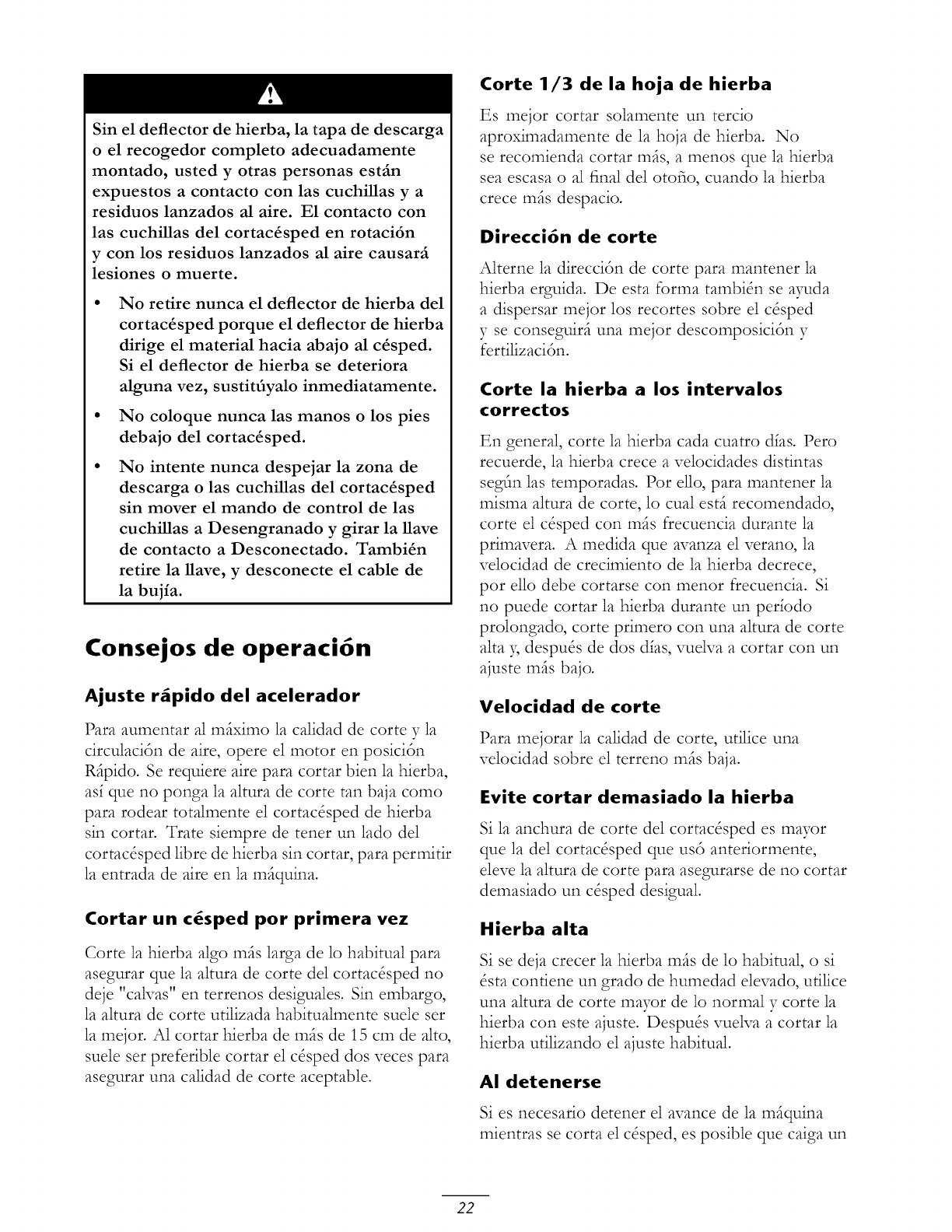
Sin el deflector de hierba, la tapa de descarga
oel recogedor completo adecuadamente
montado, usted y otras personas est_n
expuestos a contacto con las cuchillas y a
residuos lanzados al aire. E1 contacto con
las cuchillas del cortac_sped en rotaci6n
y con los residuos lanzados al aire causar_
lesiones o muerte.
No retire nunca el deflector de hierba del
cortac_sped porque el deflector de hierba
dirige el material hacia abajo al c_sped.
Si el deflector de hierba se deteriora
alguna vez, sustitfiyalo inmediatamente.
No coloque nunca las manos o los pies
debajo del cortac_sped.
No intente nunca despejar la zona de
descarga o las cuchillas del cortac_sped
sin mover el mando de control de las
cuchillas a Desengranado y girar la nave
de contacto a Desconectado. Tambi_n
retire la nave, y desconecte el cable de
la bujia.
Consejos de operaci6n
Ajuste rfipido del acelerador
Para aumentar al miximo la calidad de corte y la
circulaci6n de aire, opere el motor en posici6n
Ripido. Se requiere aire para cortar bien la hierba,
as_ que no ponga la altura de corte tan baja como
para rodear totalmente el cortac&ped de hierba
sin cortar. Trate siempre de tenet un 1ado del
cortac&ped libre de hierba sin cortar, para permitir
la entrada de aire en la m@uina.
Cortar un c_sped pot primera vez
Corte la hierba algo mis larga de lo habitual para
asegurar que la altura de corte del cortac&ped no
deje "caNas" en terrenos desiguales. Sin embargo,
la altura de corte utilizada habitualmente suele set
la mejor. A1 cortar hierba de mis de 15 cm de alto,
suele ser preferible cortar el c&ped dos veces para
asegurar una calidad de corte aceptable.
Corte 1/3 de la hoja de hierba
Es mejor cortar solamente un tercio
aproximadamente de la hoja de hierba. No
se recomienda cortar mis, a menos que la hierba
sea escasa o al final del otofio, cuando la hierba
crece mis despacio.
Direcci6n de corte
Alterne la direcci6n de corte para mantener la
hierba erguida. De esta forma tambi_n se ayuda
a dispersar mejor los recortes sobre el c&ped
y se conseguiri una mejor descomposici6n y
fertilizaci6n.
Corte la hierba a los intervalos
col'rectos
En general, corte la hierba cada cuatro d_as. Pero
recuerde, la hierba crece a velocidades distintas
segfin 1as temporadas. Por e11o,para mantener la
misma altura de corte, lo cual esti recomendado,
corte el c&ped con mis frecuencia durante la
primavera. A medida que avanza el verano, la
velocidad de crecimiento de la hierba decrece,
por ello debe cortarse con menor frecuencia. Si
no puede cortar la hierba durante un per_odo
prolongado, corte primero con una altura de corte
alta 5 despu& de dos d_as, vuelva a cortar con un
ajuste mils bajo.
Velocidad de corte
Para mejorar la calidad de corte, utilice una
velocidad sobre el terreno mis baja.
Evite cortar demasiado la hierba
Si la anchura de corte de1 cortac&ped es mayor
que la de1 cortac&ped que usd anteriormente,
eleve la altura de corte para asegurarse de no cortar
demasiado un c&ped desigual.
Hierba alta
Si se deja crecer la hierba mis de lo habitual, o si
&ta contiene un grado de humedad elevado, ufilice
una altura de corte mayor de lo normal y corte la
hierba con este ajuste. Despu& vuelva a cortar la
hierba utilizando el ajuste habitual.
AI detenerse
Si es necesario detener el avance de la miquina
mientras se corta el c&ped, es posible que caiga un
22
mont6n de recortes sobre el c0sped. Para evitar
esto, dirljase a una zona de1 c&ped que haya sido
segada, con las cuchillas engranadas.
Mantenga limpia la parte inferior del
cortac_sped
Limpie los recortes y la suciedad de los bajos de1
cortac&ped despu& de cada uso. Si la hierba
y la suciedad se acumulan en el interior del
cortac&ped, se deteriorarfi la calidad del corte.
Mantenimiento de las cuchillas
Mantenga las cuchillas afiladas durante toda la
temporada de corte, ya que una cuchilla afilada
corta limpiamente y sin rasgar o deshilachar las
hojas de hierba. Si se rasgan o se deshilachan, los
bordes de las hojas se secarfin, lo cual retardarfi
su crecimiento y favorecerfi la aparici6n de
enfermedades. Compruebe cada dla que las
cuchillas de corte estfin afiladas y que no estfin
desgastadas o dafiadas. Elimine cualquier mella
con una lima, y afile las cuchillas si es necesario.
Si una cuchilla estfi desgastada o deteriorada,
sustittlyala inmediatamente pot una cuchilla nueva
genuina Toro.
23
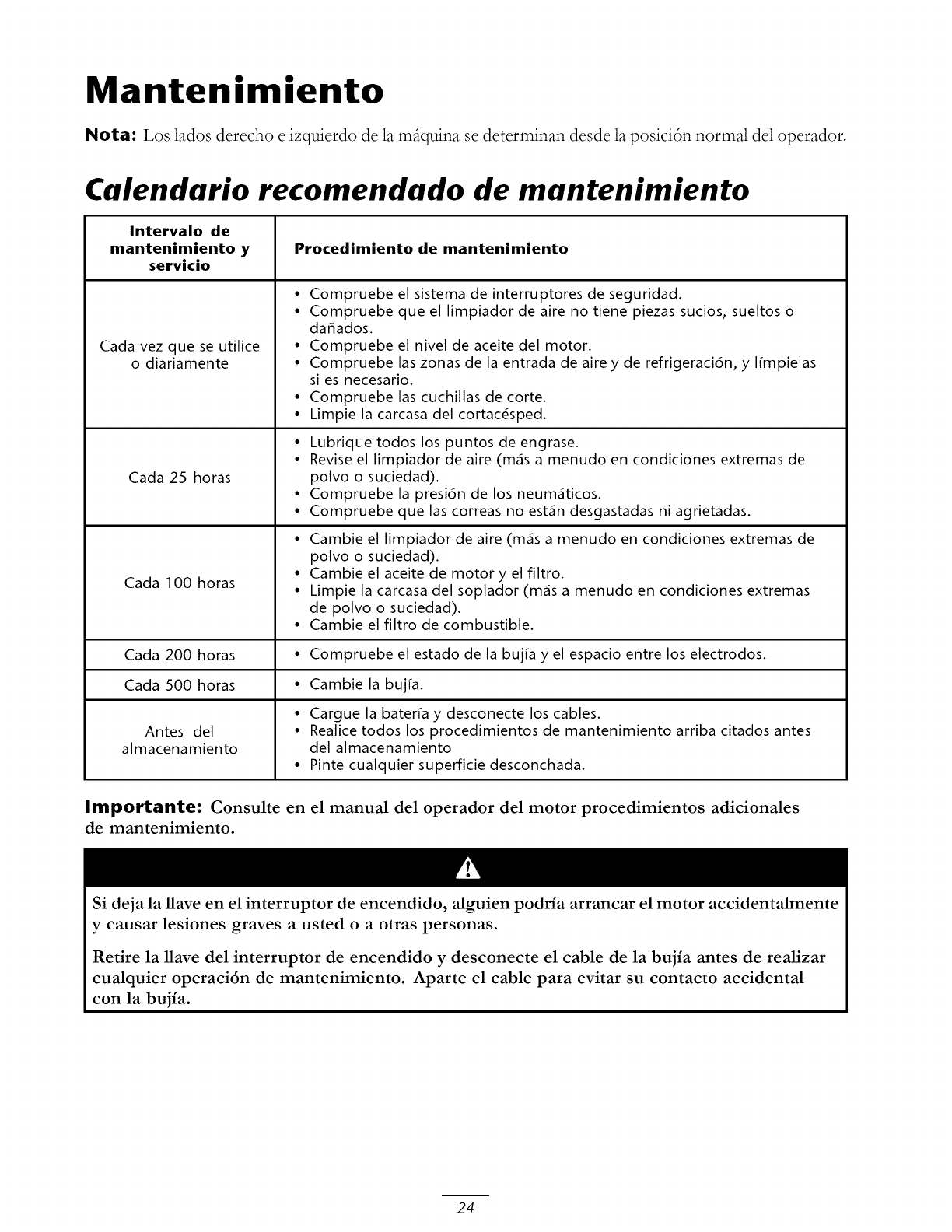
Mantenimiento
Nota: Los lados derecho e izquierdo de la mfiquina se determinan desde la posicidn normal del operador.
Calendario recomendado de mantenimiento
Intervalo de
mantenimiento y
servicio
Cada vez que se utilice
o diariamente
Cada 25 horas
Cada 1O0 horas
Procedimiento de mantenimiento
•Compruebe el sistema de interruptores de seguridad.
• Compruebe que el limpiador de aire no tiene piezas sucios, sueltos o
daffados.
• Compruebe el nivel de aceite del motor.
• Compruebe las zonas de la entrada de aire y de refrigeraci6n, y ffmpielas
si es necesario.
• Compruebe las cuchillas de corte.
• Limpie la carcasa del cortacesped.
• Lubrique todos los puntos de engrase.
• Revise el limpiador de aire (m_s a menudo en condiciones extremas de
polvo o suciedad).
• Compruebe la presion de los neum_ticos.
• Compruebe que las correas no est_n desgastadas ni agrietadas.
• Cambie el limpiador de aire (m_s a menudo en condiciones extremas de
polvo o suciedad).
• Cambie el aceite de motor y el filtro.
• Limpie la carcasa del soplador (m_s a menudo en condiciones extremas
de polvo o suciedad).
• Cambie el filtro de combustible.
Cada 200 horas • Compruebe el estado de la bujra y el espacio entre los electrodos.
Cada 500 horas • Cambie la buj[a.
• Cargue la bateffa y desconecte los cables.
Antes del • Realice todos los procedimientos de mantenimiento arriba citados antes
almacenamiento del almacenamiento
• Pinte cualquier superficie desconchada.
Importante: Consulte en el manual del operador del motor procedimientos adicionales
de mantenimiento.
Si deja la Have en el interruptor de encendido, alguien podria arrancar el motor accidentalmente
y causar lesiones graves a usted o a otras personas.
Retire la Have del interruptor de encendido y desconecte el cable de la bujia antes de realizar
cualquier operaci6n de mantenimiento. Aparte el cable para evitar su contacto accidental
con la bujia.
24
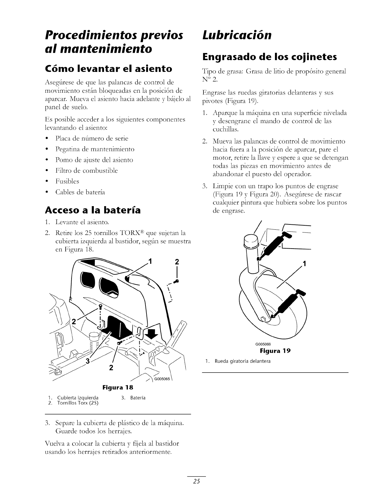
Procedimientos previos
al mantenimiento
C6mo levantar el asiento
Aseg_rese de que las palancas de control de
movimiento estfin bloqueadas en la posicidn de
aparcar. Muew_ el asiento hacia adelante y bfijelo al
panel de suelo.
Es posible acceder a los siguientes componentes
levantando el asiento:
Placa de n6mero de serie
Pegatina de mantenimiento
Pomo de ajuste de1 asiento
Filtro de combustible
Fusibles
•Cables de bateda
Acceso a la bateria
,
2.
Levante el asiento.
Retire los 25 tornillos TORX :R:'que sujetan la
cubierta izquierda al bastidor, segtln se muestra
en Figura 18.
2
I
\
2
Figura 18
1. Cubierta izquierda 3. Bater[a
2. Tornillos Torx (25)
J
I G00506
Lubricaci6n
Engrasado de los cojinetes
Tipo de grasa: Grasa de litio de propdsito general
N ° 2.
Engrase las ruedas giratorias delanteras y sus
pivotes (Figura 19).
1. Aparque la mfiquina en una superficie nivelada
y desengrane el mando de control de las
cuchillas.
,
,
Mueva las palancas de control de movimiento
hacia fuera a la posicidn de aparcar, pare el
motor, retire la llave y espere a que se detengan
todas las piezas en movimiento antes de
abandonar el puesto de1 operador.
Limpie con un trapo los puntos de engrase
(Figura 19 y Figura 20). Asegtlrese de rascar
cualquier pintura que hubiera sobre los puntos
de engrase.
1.
J
G005066
Figura 19
Rueda giratoria delantera
3. Separe la cubierta de plfistico de la mfiquina.
Guarde todos los herrajes.
Vuelva a colocar la cubierta y fijela al bastidor
usando los herrajes retirados anteriormente.
25
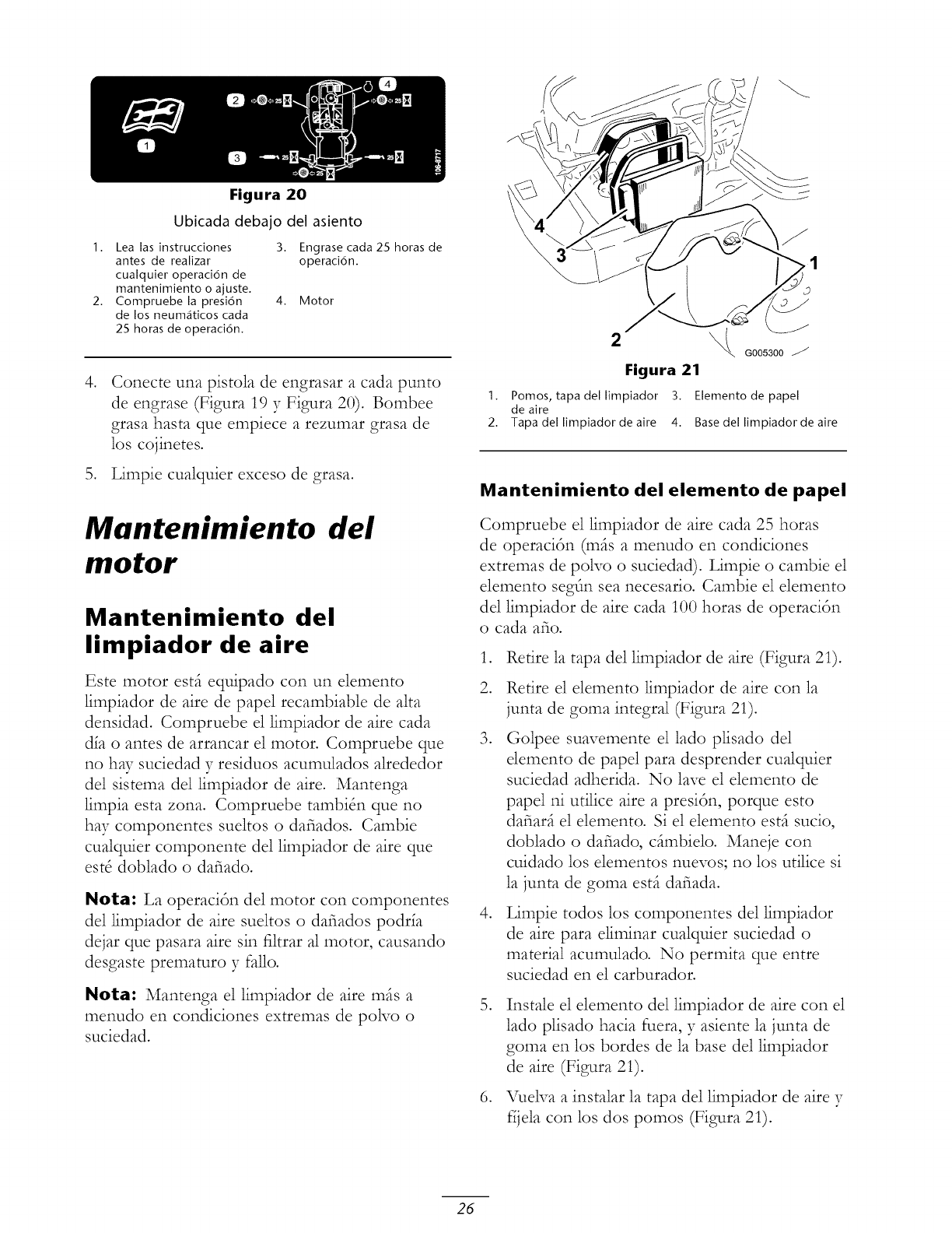
Figura 20
Ubicada debajo del asiento
I. Lea las instrucciones 3. Engrase cada 25 horas de
antes de realizar operaci6n.
cualquier operaci6n de
mantenimiento o ajuste.
2. Compruebe la presi6n 4. Motor
de los neum_ticos cada
25 horas de operaci6n.
,Conecte una pistola de engrasar a cada punto
de engrase (Figura 19 y Figura 20). Bombee
grasa hasta que empiece a rezumar grasa de
los cojinetes.
5. Limpie cualquier exceso de grasa.
Mantenimiento del
motor
Mantenimiento del
limpiador de aire
Este motor estfi equipado con un elemento
limpiador de aire de papel recambiable de alta
densidad. Compruebe el limpiador de aire cada
dla o antes de arrancar el motor• Compruebe que
no hay suciedad y residuos acumulados alrededor
del sistema del limpiador de aire. Mantenga
limpia esta zona. Compruebe tambiSn que no
hay componentes sueltos o dafiados. Cambie
cualquier componente de1 limpiador de aire que
est8 doblado o dafiado.
Nota: La operacitn de1 motor con componentes
del limpiador de aire sueltos o dafiados podrla
dejar que pasara aire sin filtrar al motor, causando
desgaste prematuro y fallo.
Nota: Mantenga el limpiador de aire mils a
menudo en condiciones extremas de polvo o
suciedad.
1.
2.
2G00sa00
Figura 21
Pomos, tapa del limpiador 3. Elemento de papel
de aire
Tapa del limpiador de aire 4. Base del limpiador de aire
Mantenimiento del elemento de papel
Compruebe el limpiador de aire cada 25 horas
de operacitn (mils a menudo en condiciones
extremas de polvo o suciedad). Limpie o cambie el
elemento segtln sea necesario. Cambie el elemento
de1 limpiador de aire cada 100 horas de operacitn
o cada afio.
.
2.
.
.
Retire la tapa del limpiador de aire (Figura 21).
Retire el elemento limpiador de aire con la
junta de goma integral (Figura 21)•
Golpee suavemente el lado plisado de1
elemento de papel para desprender cualquier
suciedad adherida. No lave el elemento de
papel ni udlice aire a presitn, porque esto
dafiarfi el elemento. Si el elemento estfi sucio,
doblado o dafiado, cfimbielo. Maneje con
cuidado los elementos nuevos; no los utilice si
la junta de goma estfi dafiada.
Limpie todos los componentes del limpiador
de aire para eliminar cualquier suciedad o
material acumulado. No permita que entre
suciedad en el carburador.
.
Instale el elemento de1 limpiador de aire con el
1ado plisado hacia fuera, y asiente la junta de
goma en los bordes de la base del limpiador
de aire (Figura 21).
VuekTa a instalar la tapa del limpiador de aire y
fljela con los dos pomos (Figura 21)•
26
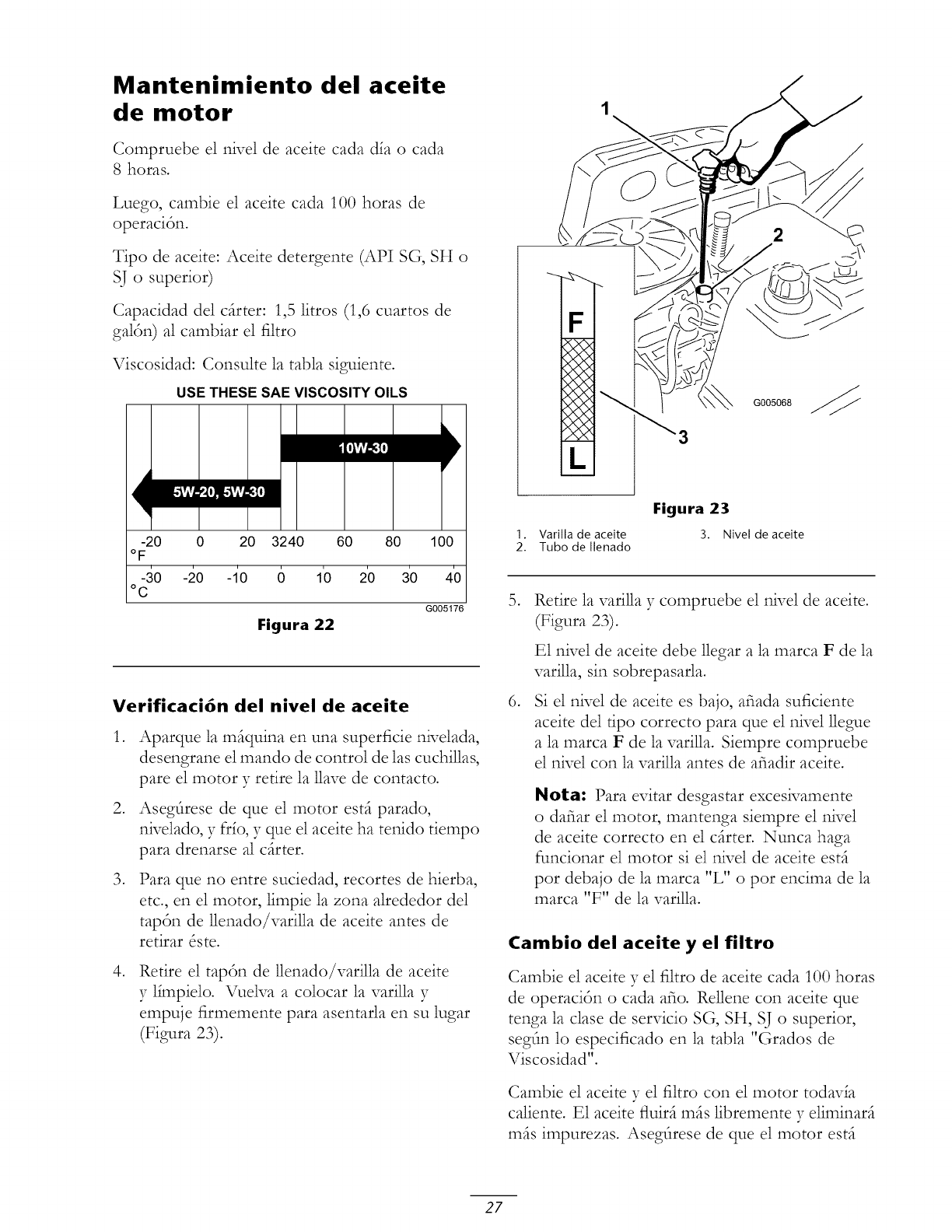
Mantenimiento del aceite
de motor
Compruebe el nivel de aceite cada dfa o cada
8 horas.
Luego, cambie el aceite cada 100 horas de
operaci6n.
Tipo de aceite: Aceite detergente (API SG, SH o
SJ o superior)
Capacidad del cfirter: 1,5 litros (1,6 cuartos de
galdn) al cambiar el filtro
Viscosidad: Consulte la tabla siguiente.
USE THESE SAE VISCOSITY OILS
1
-20 0 20 3240 60 80 100
oF
-30 -20 -1'0 (5 1'0 2'0 3'0 4'0
° C
G005176
Figura 22
Verificaci6n del nivel de aceite
,
,
,
,
Aparque la mfiquina en una superficie nivelada,
desengrane el mando de control de las cuchillas,
pare el motor y retire la 1lave de contacto.
Asegfirese de que el motor estfi parado,
nivelado, y frfo, y que el aceite ha tenido tiempo
para drenarse al cfirter.
Para que no entre suciedad, recortes de hierba,
etc., en el motor, limpie la zona alrededor del
tapdn de llenado/varilla de aceite antes de
retirar _ste.
Retire el tapdn de llenado/varilla de aceite
y ffmpielo. Vuelva a colocar la varilla y
empuje firmemente para asentarla en su lugar
(Figura 23).
F
2
G005068
Figura 23
1. Varilla de aceite 3. Nivel de aceite
2. Tubo de Ilenado
,
Retire la varilla y compruebe el nivel de aceite.
(Figura 23)•
E1 nivel de aceite debe llegar a la marca F de la
varilla, sin sobrepasarla.
Si el nivel de aceite es bajo, aria& suficiente
aceite del tipo correcto para que el nive111egue
a la marca F de la varilla. Siempre compruebe
el nivel con la varilla antes de afiadir aceite.
Nota: Para evitar desgastar excesivamente
o dafiar el motor, mantenga siempre el nivel
de aceite correcto en el critter. Nunca haga
funcionar el motor si el nivel de aceite estfi
pot debajo de la marca "L" o pot encima de la
marca "F" de la varilla.
Cambio del aceite y el filtro
Cambie el aceite y el filtro de aceite cada 100 horas
de operacidn o cada afio. Rellene con aceite que
tenga la clase de servicio SG, SH, SJ o superior,
segtln lo especificado en la tabla "Grados de
Viscosidad".
Cambie el aceite y el filtro con el motor todavfa
caliente. E1 aceite fluirfi mils libremente y eliminarfi
mils impurezas. Asegfirese de que el motor estfi
27
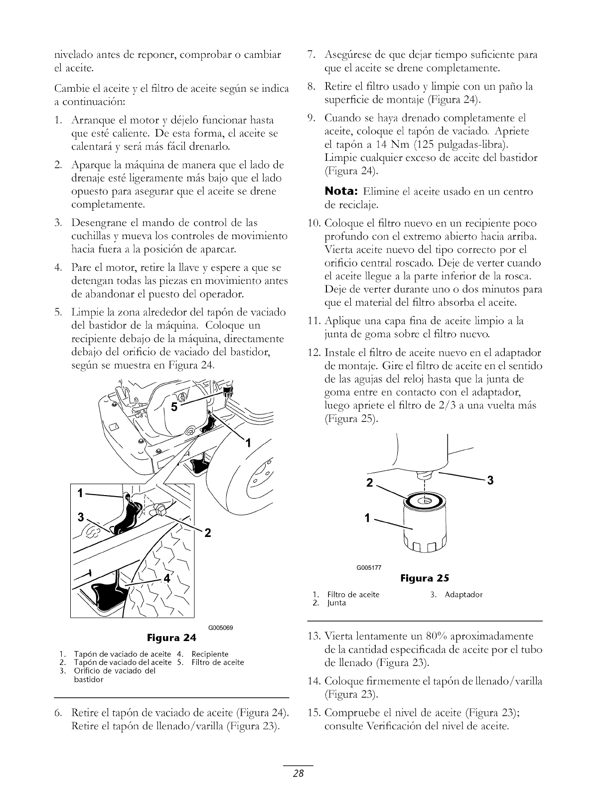
nivelado antes de reponer, comprobar o cambiar
el aceite.
Cambie el aceite y el filtro de aceite segtln se indica
a continuacidn:
,
,
,
,
Arranque el motor y dSjelo funcionar hasta
que est8 caliente. De esta forma, el aceite se
calentarfi y serfi mils fficil drenarlo.
Aparque la mfiquina de manera que el lado de
drenaje est8 ligeramente mils bajo que el lado
opuesto para asegurar que el aceite se drene
completamente.
Desengrane el mando de control de las
cuchillas y mueva los controles de movimiento
hacia fuera a la posicidn de aparcar.
Pare el motor, retire la llave y espere a que se
detengan todas las piezas en movimiento antes
de abandonar el puesto del operador.
Limpie la zona alrededor del tapdn de vaciado
del bastidor de la mfiquina. Coloque un
recipiente debajo de la mfiquina, directamente
debajo del orificio de vaciado del bastidor,
segfin se muestra en Figura 24.
,
,
,
10.
11.
12.
Asegtlrese de que dejar tiempo suficiente para
que el aceite se drene completamente.
Retire el filtro usado y limpie con un patio la
superficie de montaje (Figura 24)•
Cuando se haya drenado completamente el
aceite, coloque el tapdn de vaciado. Apriete
el tapdn a 14 Nm (125 pulgadas-libra).
Limpie cualquier exceso de aceite del bastidor
(Figura 24).
Nota: Elimine el aceite usado en un centro
de reciclaje.
Coloque el filtro nuevo en un recipiente poco
profundo con el extremo abierto hacia arriba.
Vierta aceite nuevo del tipo correcto por el
orificio central roscado. Deje de verter cuando
el aceite llegue a la parte inferior de la rosca.
Deje de verter durante uno o dos minutos para
que el material del filtro absorba el aceite.
Aplique una capa fina de aceite limpio a la
junta de goma sobre el filtro nuevo.
Instale el filtro de aceite nuevo en el adaptador
de montaje. Gire el filtro de aceite en el sentido
de las agujas del reloj hasta que la junta de
goma entre en contacto con el adaptador,
luego apriete el filtro de 2/3 a una xqaelta mils
(Figura 25).
G005177
I. Filtro de aceite
2. Junta
Figura 25
3. Adaptador
,
G005069
Figura 24
I. Tap6n de vaciado de aceite 4. Recipiente
2. Tap6n devaciadodelaceite 5. Filtro de aceite
3. Orificio de vaciado del
bastidor
Retire el tapdn de vaciado de aceite (Figura 24).
Retire el tapdn de llenado/varilla (Figura 23)•
13. Vierta lentamente un 80% aproximadamente
de la cantidad especificada de aceite por el tubo
de llenado (Figura 23).
14. Coloque firmemente el tapdn de llenado/varilla
(Figura 23).
15. Compruebe el nivel de aceite (Figura 23);
consulte Verificacidn del nivel de aceite.
28
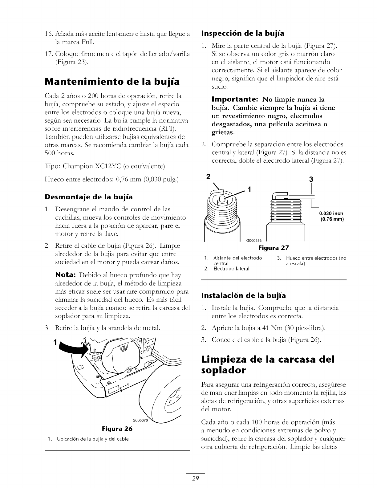
16. Afiada mils aceite lentamente hasta que llegue a
la marca Pull.
17. Coloque firmemente el tap6n de llenado/varilla
(Pigura 23).
Mantenimiento de la bujia
Cada 2 afios o 200 horas de operacitn, retire la
buj_a, compruebe su estado, y ajuste el espacio
entre los electrodos o coloque una buj_a nueva,
segtn sea necesario. La buj_a cumple la normatNa
sobre interferencias de radiofrecuencia (RFI).
TambiSn pueden utilizarse buj_as equivalentes de
otras marcas. Se recomienda cambiar la buj_a cada
500 horas.
Tipo: Champion XC12YC (o equivalente)
Hueco entre electrodos: 0,76 mm (0,030 pulg.)
Desmontaje de la bujia
,
,
Desengrane el mando de control de las
cuchillas, mueva los controles de movimiento
hacia fuera a la posicitn de aparcar, pare el
motor y retire la 1lave.
Retire el cable de buj_a (Figura 26). Limpie
alrededor de la bujfa para evitar que entre
suciedad en el motor y pueda causar dafios.
Nora: Debido al hueco profundo que ha3"
alrededor de la buj_a, el m&odo de limpieza
mils eficaz suele ser usar aire comprimido para
eliminar la suciedad del hueco. Es rafts fficil
acceder a la buj_a cuando se retira la carcasa del
soplador para su limpieza.
3. Retire la bujfa y la arandela de metal.
1.
G005070
Figura 26
Ubicaci6n de la buj_a ydel cable
Inspecci6n de la bujia
,Mire la parte central de la buj_a (Pigura 27).
Si se observa un color gris o marrtn claro
en el aislante, el motor estfi funcionando
correctamente. Si el aislante aparece de color
negro, significa que el limpiador de aire estfi
sucio.
,
Importante: No limpie nunca la
bujia. Cambie siempre la bujia si tiene
un revestimiento negro, electrodos
desgastados, una pelicula aceitosa o
grietas.
Compruebe la separacidn entre los electrodos
central y lateral (Figura 27). Si la distancia no es
correcta, doble el electrodo lateral (Figura 27).
2 3
_1 Lo.o3o inch
(0.76 mm)
G000533
Figura 27
1. Aislante del electrodo 3. Hueco entre electrodos (no
central a escala)
2. Electrodo lateral
Instalaci6n de la bujia
1. Instale la buj_a. Compruebe que la distancia
entre los electrodos es correcta.
2. Apriete la buj_a a 41 Nm (30 pies-libra).
3. Conecte el cable a la buj_a (Pigura 26).
Limpieza de la carcasa del
soplador
Para asegurar una reffigeraci6n correcta, asegtlrese
de mantener limpias en todo momento la rejilla, las
aletas de refrigeraci6n, y otras superficies externas
del motor.
Cada afio o cada 100 horas de operacitn (mils
a menudo en condiciones extremas de poNo y
suciedad), retire la carcasa de1 soplador y cualquier
otra cubierta de refrigeracitn. Limpie las aletas
29
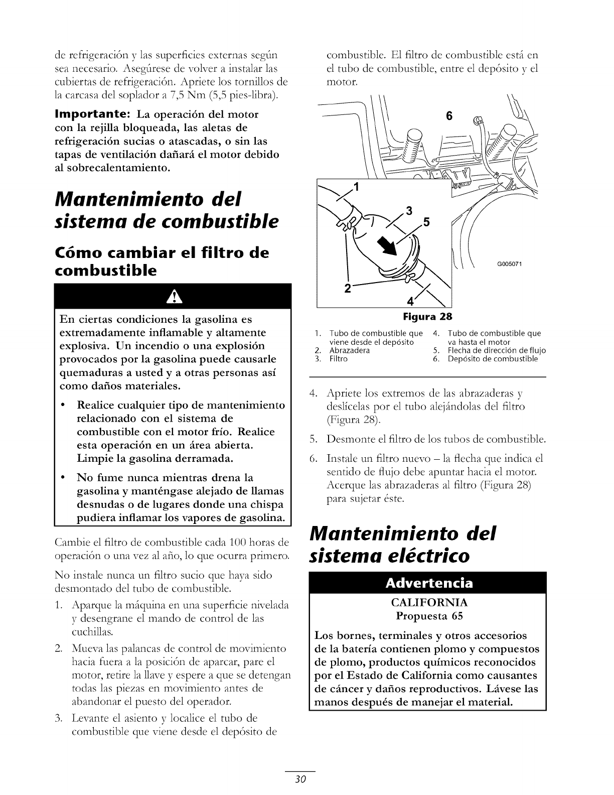
de refrigeracitn y 1as superficies externas segtn
sea necesario. Asegt]rese de voNer a instalar las
cubiertas de refrigeracitn. Apriete los tornillos de
la carcasa del soplador a 7,5 Nm (5,5 pies-libra).
Importante: La operaci6n del motor
con la rejilla bloqueada, las aletas de
refrigeraci6n sucias o atascadas, o sin las
tapas de ventilaci6n dafiar_ el motor debido
al sobrecalentamiento.
Mantenimiento del
sistema de combustible
C6mo cambiar el filtro de
combustible
En ciertas condiciones la gasolina es
extremadamente inflamable y altamente
explosiva. Un incendio o una explosi6n
provocados por la gasolina puede causarle
quemaduras a usted y a otras personas asi
como dafios materiales.
Realice cualquier tipo de mantenimiento
relacionado con el sistema de
combustible con el motor frio. Realice
esta operaci6n en un _rea abierta.
Limpie la gasolina derramada.
No fume nunca mientras drena la
gasolina y mant4ngase alejado de llamas
desnudas o de lugares donde una chispa
pudiera inflamar los vapores de gasolina.
Cambie el filtro de combustible cada 100 horas de
operacidn o una vez al afio, lo que ocurra primero.
No instale nunca un filtro sucio que haya sido
desmontado del tubo de combustible.
1. Aparque la mfiquina en una superficie nivelada
y desengrane el mando de control de las
cuchillas.
2. Mueva las palancas de control de movimiento
hacia fuera a la posicidn de aparcar, pare el
motor, retire la 1lave y espere a que se detengan
todas las piezas en movimiento antes de
abandonar el puesto del operador.
3. Levante el asiento y localice el tubo de
combustible que viene desde el depdsito de
combustible. E1 filtro de combustible estfi en
el tubo de combustible, entre el depdsito y el
motor.
6
2
G005071
Figura 28
1. Tubo de combustible que 4. Tubo de combustible que
viene desde el dep6sito va hasta el motor
2. Abrazadera 5. Flecha de direcci6n de flujo
3. Filtro 6. Dep6sito de combustible
,
6.
Apriete los extremos de las abrazaderas y
desllcelas por el tubo alejfindolas del filtro
(Figura 28).
Desmonte el filtro de los tubos de combustible.
Instale un filtro nuevo - la flecha que indica el
sentido de flujo debe apuntar hacia el motor•
Acerque las abrazaderas al filtro (Figura 28)
para sujetar &te.
Mantenimiento del
sistema el ctrico
CALIFORNIA
Propuesta 65
Los bornes, terminales y otros accesorios
de la bateria contienen plomo y compuestos
de plomo, productos quimicos reconocidos
por el Estado de California como causantes
de c_ncer y dafios reproductivos. L_vese las
manos despu4s de manejar el material.
30
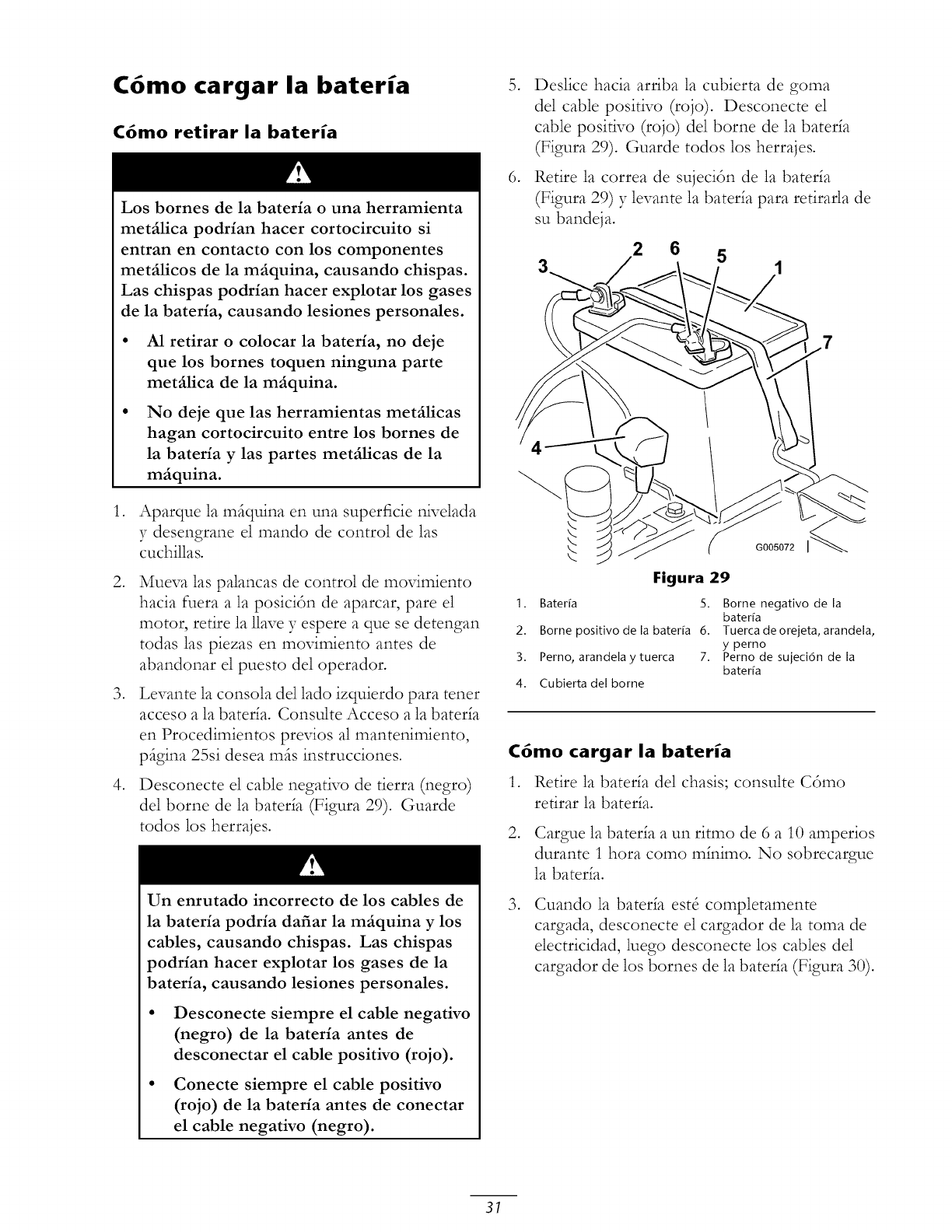
C6mo cargar la bateria
C6mo retirar la bateria
,
,
,
,
Los bornes de la bateria o una herramienta
metfilica podrian hacer cortocircuito si
entran en contacto con los componentes
metfilicos de la mfiquina, causando chispas.
Las chispas podrian hacer explotar los gases
de la bateria, causando lesiones personales.
• A1 retirar o colocar la bateria, no deje
que los bornes toquen ninguna parte
metfilica de la mfiquina.
No deje que las herramientas metfilicas
hagan cortocircuito entre los bornes de
la bateria y las partes metfilicas de la
mfiquina.
Aparque la mfiquina en una superficie nivelada
y desengrane el mando de control de las
cuchillas.
Mueva las palancas de control de movimiento
hacia fuera a la posici6n de aparcar, pare el
motor, retire la llave y espere a que se detengan
todas las piezas en movimiento antes de
abandonar el puesto de1 operador.
Levante la consola de1 lado izquierdo para tener
acceso a la bater_a. Consulte Acceso a la bater_a
en Procedimientos previos al mantenimiento,
pfigina 25si desea mils instrucciones.
Desconecte el cable negativo de tierra (negro)
de1 borne de la bater_a (Figura 29). Guarde
todos los herrajes.
Un enrutado incorrecto de los cables de
la bateria podria dafiar la mfiquina y los
cables, causando chispas. Las chispas
podrian hacer explotar los gases de la
bateria, causando lesiones personales.
• Desconecte siempre el cable negativo
(negro) de la bateria antes de
desconectar el cable positivo (rojo).
• Conecte siempre el cable positivo
(rojo) de la bateria antes de conectar
el cable negativo (negro).
,
,
Deslice hacia arriba la cubierta de goma
del cable positivo (rojo). Desconecte el
cable positivo (rojo) de1 borne de la baterla
(Figura 29). Guarde todos los herrajes.
Retire la correa de sujeci6n de la baterla
(Figura 29) y levante la baterla para retirarla de
su bandeja.
2 6 5
4
Figura 29
1. Bater_a 5.
2. Borne positivo de la bater_a 6.
3. Perno, arandela ytuerca 7.
4. Cubierta del borne
G005072 I
Borne negativo de la
bater[a
Tuerca de orejeta, arandela,
yperno
Perno de sujeci6n de la
bater{a
C6mo cargar la bateria
1. Retire la bater_a de1 chasis; consulte C6mo
refirar la baterla.
,Cargue la baterla a un ritmo de 6 a 10 amperios
durante 1 hora como mlnimo. No sobrecargue
la baterla.
,Cuando la baterla est_ completamente
cargada, desconecte el cargador de la toma de
electricidad, luego desconecte los cables del
cargador de los bornes de la baterla (Figura 30).
31

2
3
1
G000538
Figura 30
I. Borne positivo de la bater[a 3. Cable rojo (+) del cargador
2. Borne negativo de la 4. Cable negro (-) del
bater[a cargador
Nota: No haga funcionar la mfiquina con la
bater_a desconectada; puede causar dafios al
sistema el&trico.
Instalaci6n de la bater[a
,
,
,
Coloque la bater_a en la bandeja, con los bornes
hacia el puesto del operador (Figura 29).
Conecte primero el cable positivo (rojo) al
borne positivo (+) de la bater_a usando los
herrajes que retir6 anteriormente.
Conecte el cable negativo al borne negativo
(-) de la bater_a usando los herrajes que retir6
anteriormente.
,
,
Deslice la cubierta de goma roja sobre el borne
positivo (rojo) de la baterla.
Fije la bater_a con la correa de sujecidn
(Figura 29)•
Instale la consola del lado izquierdo.
Consulte Acceso a la bater_a en
Procedimientos previos al mantenimiento,
pSgina 25 si desea ross instrucciones.
Mantenimiento de los
fusibles
E1 sistema el&trico est_ protegido con fusibles.
No requiere mantenimiento; no obstante, si se
funde un fusible, compruebe que no ha 3-aver_a ni
cortocircuito en el componente/circuito.
Fusible:
• Principal FI - 30 amperios, tipo chapa
• Circuito de carga F2 - 25 amperios, tipo chapa
1. Levante el asiento para tener acceso al
portafusibles (Figura 31).
2. Para cambiar un fusible, tire del fusible para
retirarlo (Figura 31).
2
Figura 31
1. Principal- 30 amperios 2. Circuito de carga -
25 amperios
Mantenimiento del
sistema de transmisi6n
Comprobaci6n de la presi6n
de los neum ticos
Mantenga la presi6n especificada de los neumSticos
delanteros y traseros. Una presi6n desigual en los
neumSticos puede hacer que el corte sea desigual.
Verifique la presi6n en la v,filvula cada 25 horas
de operaci6n o cada rues, lo que ocurra primero
(Figura 32). Las lecturas de presi6n son ross
exactas cuando los neumSticos estSn fr_os.
NeumSticos traseros: 90 kPa (13 psi)
NeumSticos delanteros (ruedas giratorias): 139 kPa
(35 psi)
Figura 32
I. Vastago de la valvula
32
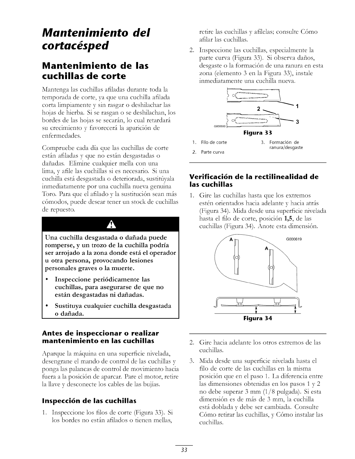
Mantenimiento
cortac sped
del
Mantenimiento de las
cuchillas de corte
Mantenga las cuchillas afiladas durante toda la
temporada de corte, ya que una cuchilla afilada
corta limpiamente y sin rasgar o deshilachar las
hojas de hierba. Si se rasgan o se deshilachan, los
bordes de las hojas se secarfin, lo cual retardarfi
su crecimiento y favorecerfi la aparicidn de
enfermedades.
Compruebe cada d_a que las cuchillas de corte
estfin afiladas y que no estfin desgastadas o
dafiadas. Elimine cualquier mella con una
lima, y afile las cuchillas si es necesario. Si una
cuchilla estfi desgastada o deteriorada, sustitfiyala
inmediatamente pot una cuchilla nueva genuina
Toro. Para que el afilado y la sustituci6n sean mils
cSmodos, puede desear tener un stock de cuchillas
de repuesto.
Una cuchilla desgastada odafiada puede
romperse, y un trozo de la cuchilla podria
ser arrojado a la zona donde estfi el operador
u otra persona, provocando lesiones
personales graves o la muerte.
• Inspeccione peri6dicamente las
cuchillas, para asegurarse de que no
estfin desgastadas ni dafiadas.
• Sustituya cualquier cuchilla desgastada
o dafiada.
Antes de inspeccionar o realizar
mantenimiento en las cuchillas
Aparque la mfiquina en una superficie nivelada,
desengrane el mando de control de las cuchillas y
ponga las palancas de control de movimiento hacia
fuera a la posiciSn de aparcar. Pare el motor, retire
la 1lavey desconecte los cables de las buj_as.
Inspecci6n de las cuchillas
1. Inspeccione los filos de corte (Figura 33). Si
los bordes no estfin afilados o tienen mellas,
,
retire las cuchillas y afflelas; consulte C6mo
afilar las cuchillas.
Inspeccione las cuchillas, especialmente la
parte curva (Figura 33). Si observa dafios,
desgaste o la formaci6n de una ranura en esta
zona (elemento 3 en la Figura 33), instale
inmediatamente una cuchilla nueva.
' 1
2_
Gooos_oI- _ 3
Figura 33
I. Filo de corte 3. Formaci6n de
ranu ra/desgaste
2. Parte curva
Verificaci6n de la rectilinealidad de
las cuchillas
,Gire las cuchillas hasta que los extremos
estSn orientados hacia adelante y hacia atrfis
(Figura 34). Mida desde una superficie nivelada
hasta el filo de corte, posiciSn 1,5, de las
cuchillas (Figura 34). Anote esta dimensiSn.
G000619
Figura 34
,
,
Gire hacia adelante los otros extremos de las
cuchillas.
Mida desde una superficie nivelada hasta el
filo de corte de 1as cuchillas en la misma
posici6n queen el paso 1. La diferencia entre
las dimensiones obtenidas en los pasos 1 y 2
no debe superar 3 mm (1/8 pulgada). Siesta
dimensiSn es de mils de 3 ram, la cuchilla
estfi doblada y debe ser cambiada. Consulte
CSmo retirar las cuchillas, y CSmo instalar las
cuchillas.
33
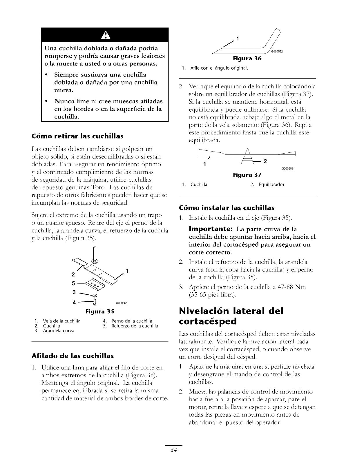
Una cuchilla doblada o dafiada podria
romperse y podria causar graves lesiones
o la muerte a usted o a otras personas.
• Siempre sustituya una cuchilla
doblada o dafiada por una cuchilla
nueva.
• Nunca lime ni cree muescas afiladas
en los bordes o en la superficie de la
cuchilla.
C6mo retirar las cuchillas
Las cuchillas deben cambiarse si golpean un
objeto s61ido, si estfin desequilibradas o si estfin
dobladas. Para asegurar un rendimiento 6primo
y el continuado cumplimiento de las normas
de seguridad de la m@uina, utilice cuchillas
de repuesto genuinas Toro. Las cuchillas de
repuesto de otros fabricantes pueden hacer clue se
incumplan las normas de seguridad.
Sujete el extremo de la cuchilla usando un trapo
o un guante grueso. Retire del eje el perno de la
cuchilla, la arandela curw_, el refuerzo de la cuchilla
y la cuchilla (Figura 35).
2
5
3
4
1. Vela de la cuchilla
2. Cuchilla
3. Arandela curva
G000551
Figura 35
4. Perno de la cuchilla
5. Refuerzo de la cuchilla
Afilado de las cuchillas
,Utilice una lima para afilar el filo de corte en
ambos extremos de la cuchilla (Figura 36).
Mantenga el fingulo original. La cuchilla
permanece equilibrada si se retira la misma
canfidad de material de ambos bordes de corte.
Figura 36
1. Afile con el ,ingulo original.
,Verifique el equilibrio de la cuchilla colocfindola
sobre un equilibrador de cuchillas (Figura 37).
Si la cuchilla se manfiene horizontal, estfi
equilibrada y puede utilizarse. Si la cuchilla
no estfi equilibrada, rebaje algo el metal en la
parte de la vela solamente (Figura 36). Repita
este procedimiento hasta que la cuchilla est8
equilibrada.
1G000553
Figura 37
1. Cuchilla 2. Equilibrador
C6mo instalar las cuchillas
1. Instale la cuchilla en el eje (Figura 35).
Importante: La parte curva de la
cuchilla debe apuntar hacia arriba, hacia el
interior del cortac_sped para asegurar un
corte correcto.
2. Instale el refuerzo de la cuchilla, la arandela
curva (con la copa hacia la cuchilla) y el perno
de la cuchilla (Figura 35).
3. Apriete el perno de la cuchilla a 47-88 Nm
(35-65 pies-libra).
Nivelaci6n lateral del
cortac6sped
Las cuchillas del cortac&ped deben estar niveladas
lateralmente. Verifique la nivelaci6n lateral cada
vez que instale el cortac&ped, o cuando observe
un corte desigual de1 c&ped.
1. Aparque la mfiquina en una superficie nivelada
y desengrane el mando de control de las
cuchillas.
,Mueva las palancas de control de movimiento
hacia fuera a la posici6n de aparcar, pare el
motor, retire la llave y espere a que se detengan
todas las piezas en movimiento antes de
abandonar el puesto del operador.
34
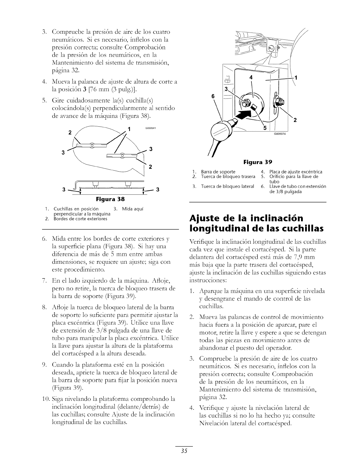
3, /
,
Compruebe la presi6n de aire de los cuatro
neumfiticos. Si es necesario, fnflelos con la
presi6n correcta; consulte Comprobaci6n
de la presi6n de los neumfiticos, en la
Mantenimiento del sistema de transmisi6n,
pfigina 32.
Mueva la palanca de ajuste de altura de corte a
la posiciSn 3 [76 mm (3 pulg.)].
Gire cuidadosamente la(s) cuchilla(s)
colocfindola(s) perpendicularmente al sentido
de avance de la mfiquina (Figura 38)•
3 3
T
Figura 38
1. Cuchillas en posici6n 3. Mida aqu[
perpendicular a la m_iquina
2. Bordes de corte exteriores
,Mida entre los bordes de corte exteriores y
la superficie plana (Figura 38). Si hay una
diferencia de mils de 5 mm entre ambas
dimensiones, se requiere un ajuste; siga con
este procedimiento.
7. En el lado izquierdo de la mfiquina. Afloje,
pero no retire, la tuerca de bloqueo trasera de
la barra de soporte (Figura 39).
,Afloje la tuerca de bloqueo lateral de la barra
de soporte lo suficiente para permitir ajustar la
placa excSntrica (Figura 39). Utilice una llave
de extensi6n de 3/8 pulgada de una llave de
tubo para manipular la placa excSntrica. Utilice
la 1lave para ajustar la altura de la plataforma
del cortac&ped a la altura deseada.
,Cuando la plataforma est8 en la posici6n
deseada, apriete la tuerca de bloqueo lateral de
la barra de soporte para fijar la posici6n nueva
(Figura 39).
10. Siga nivelando la plataforma comprobando la
inclinaci6n longitudinal (delante/detrfis) de
las cuchillas; consulte Ajuste de la inclinaci6n
longitudinal de las cuchillas.
Figura 39
1. Barra de soporte 4. Placa de ajuste excOntrica
2. Tuerca de bloqueo trasera 5. Orificio para la Ilave de
tubo
3. Tuerca de bloqueo lateral 6. Llave detubo con extensi6n
de 3/8 pulgada
Ajuste de la inclinaci6n
longitudinal de las cuchillas
Verifique la inclinaci6n longitudinal de las cuchillas
cada vez que instale el cortac&ped. Si la parte
delantera del cortac&ped estfi mils de 7,9 mm
mils baja que la parte trasera del cortac&ped,
ajuste la inclinaci6n de las cuchillas siguiendo estas
instrucciones:
1. Aparque la mfiquina en una superficie nivelada
y desengrane el mando de control de las
cuchillas.
,
,
,
Mueva las palancas de control de movimiento
hacia fuera a la posici6n de aparcar, pare el
motor, retire la llave y espere a que se detengan
todas las piezas en movimiento antes de
abandonar el puesto del operador.
Compruebe la presi6n de aire de los cuatro
neumfiticos. Si es necesario, fnflelos con la
presi6n correcta; consulte Comprobaci6n
de la presi6n de los neumfiticos, en la
Mantenimiento del sistema de transmisi6n,
pfigina 32.
Verifique y ajuste la nivelaci6n lateral de
las cuchillas si no lo ha hecho ya; consulte
Nivelaci6n lateral del cortac&ped.
35
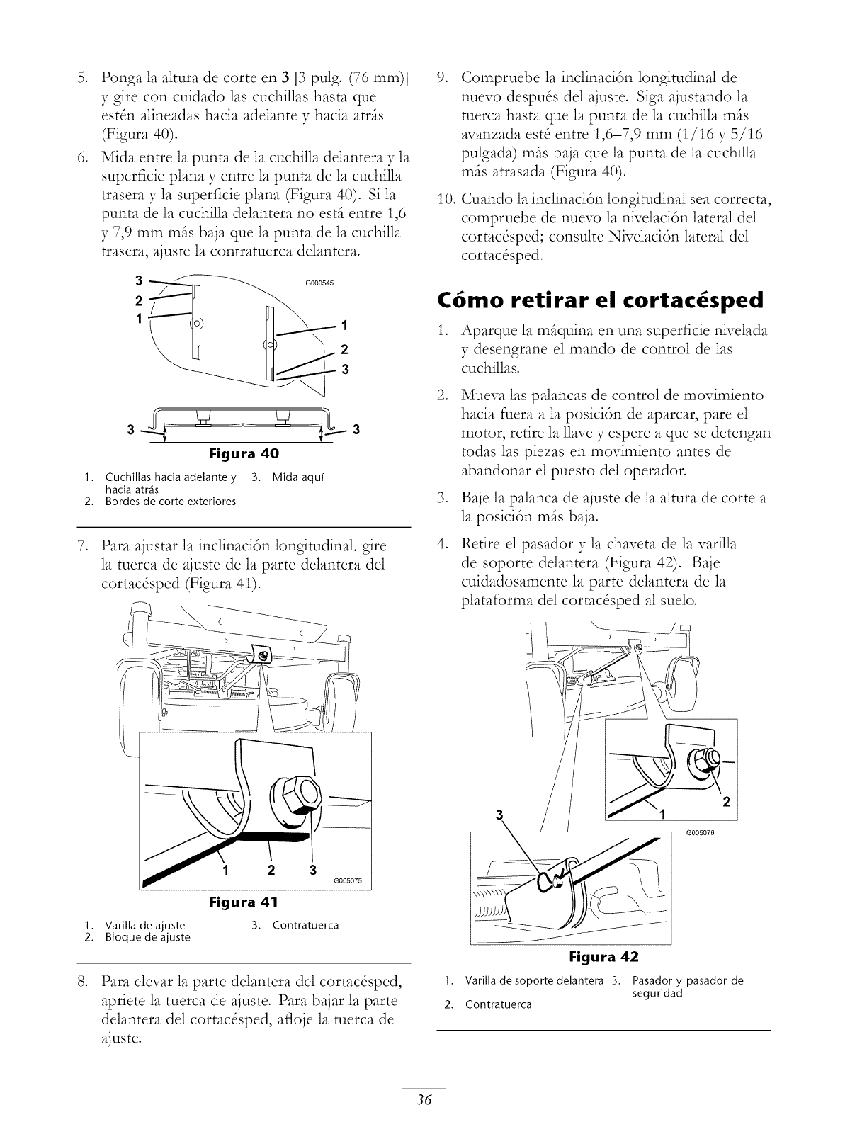
.
1.
2.
.
.
Ponga la altura de corte en 3 [3 pulg. (76 ram)]
y gire con cuidado las cuchillas hasta que
est_n alineadas hacia adelante y hacia atr_s
(Figura 40).
Mida entre la punta de la cuchilla delantera y la
superficie plana y entre la punta de la cuchilla
trasera y la superficie plana (Figura 40). Si la
punta de la cuchilla delantera no estfi entre 1,6
y 7,9 mm mils baja que la punta de la cuchilla
trasera, ajuste la contratuerca delantera.
000
2
3
Figura 40
Cuchillas hacia adelante y 3. Mida aqu_
hacia arras
Bordes de corte exteriores
3
Para ajustar la inclinacitn longitudinal, gire
la tuerca de ajuste de la parte delantera del
cortac&ped (Figura 41).
(
I. Varilla de ajuste
2. Bloquede ajuste
12 3
G005075
Figura 41
3. Contratuerca
Para elevar la parte delantera del cortac&ped,
apriete la tuerca de ajuste. Para bajar la parte
delantera del cortac&ped, aiqoje la tuerca de
ajuste.
.
10.
Compruebe la inclinacitn longitudinal de
nuevo despu& del ajuste. Siga ajustando la
tuerca hasta que la punta de la cuchilla mSs
avanzada est_ entre 1,6-7,9 mm (1/16 y 5/16
pulgada) ross baja que la punta de la cuchilla
ross atrasada (Figura 40).
Cuando la inclinacitn longitudinal sea correcta,
compruebe de nuevo la nivelacitn lateral del
cortac&ped; consulte Nivelacitn lateral del
cortac&ped.
C6mo retirar el cortac6sped
Varilla de soporte delantera 3.
Contratuerca
1. Aparque la mfiquina en una superficie nivelada
y desengrane el mando de control de las
cuchillas.
2. Mueva las palancas de control de movimiento
hacia fuera a la posicitn de aparcar, pare el
motor, retire la llave y espere a que se detengan
todas las piezas en movimiento antes de
abandonar el puesto del operador.
3. Baje la palanca de ajuste de la altura de corte a
la posicitn mSs baja.
4. Retire el pasador y la chaveta de la varilla
de soporte delantera (Figura 42). Baje
cuidadosamente la parte delantera de la
plataforma del cortac&ped al suelo.
2
3
G005076
Flgura 42
1. Pasador y pasador de
seguridad
2.
36
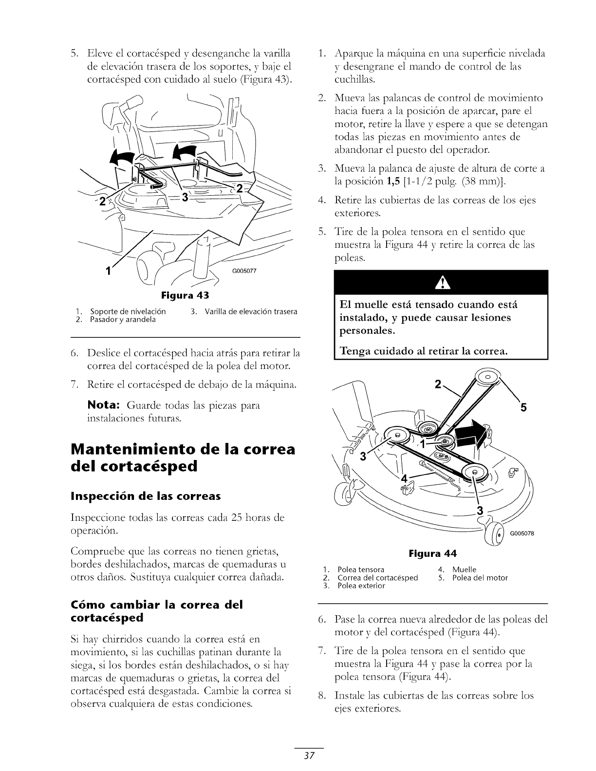
Eleve el cortac&ped 37desenganche la varilla
de elevacidn trasera de los soportes, y baje el
cortac&ped con cuidado al suelo (Figura 43).
G005077
,
,
,
,
Aparque la mfiquina en una superficie nivelada
y desengrane el mando de control de las
cuchillas.
Mueva las palancas de control de movimiento
hacia fuera a la posicidn de aparcar, pare el
motor, retire la llave y espere a que se detengan
todas las piezas en movimiento antes de
abandonar el puesto del operador.
Mueva la palanca de ajuste de altura de corte a
la posicidn 1,5 [1-1/2 pulg. (38 ram)].
Retire las cubiertas de las correas de los ejes
exteriores.
Tire de la polea tensora en el sentido que
muestra la Figura 44 y retire la correa de las
poleas.
Figura 43
1. Soporte de nivdad6n 3. Varilla de devaci6n trasera
2. Pasadory arandda
,Deslice el cortac&ped hacia atrfis para retirar la
correa del cortac&ped de la polea del motor•
7. Retire el cortac&ped de debajo de la mfiquina.
Nota: Guarde todas las piezas para
instalaciones futuras.
Mantenimiento de la correa
del cortac sped
Inspecci6n de las correas
Inspeccione todas las correas cada 25 horas de
operacidn.
Compruebe que las correas no tienen grietas,
hordes deshilachados, marcas de quemaduras u
otros dafios. Sustituya cualquier correa dafiada.
C6mo cambiar la correa del
cortac4sped
Si hay chirridos cuando la correa estfi en
movimiento, si 1as cuchillas patinan durante la
siega, si los bordes estfin deshilachados, o si hay
marcas de quemaduras o grietas, la correa del
cortac&ped estfi desgastada. Cambie la correa si
observa cualquiera de estas condiciones.
1.
2.
3.
,
,
,
E1 muelle estfi tensado cuando estfi
instalado, y puede causar lesiones
personales.
Tenga cuidado al retirar la correa.
\
\
5
G005078
Figura 44
Polea tensora 4. Muelle
Correa del cortacOsped 5. Polea del motor
Polea exterior
Pase la correa nueva alrededor de las poleas del
motor y de1 cortac&ped (Figura 44).
Tire de la polea tensora en el sentido que
muestra la Figura 44 y pase la correa por la
polea tensora (Figura 44).
Instale las cubiertas de las correas sobre los
ejes exteriores.
37
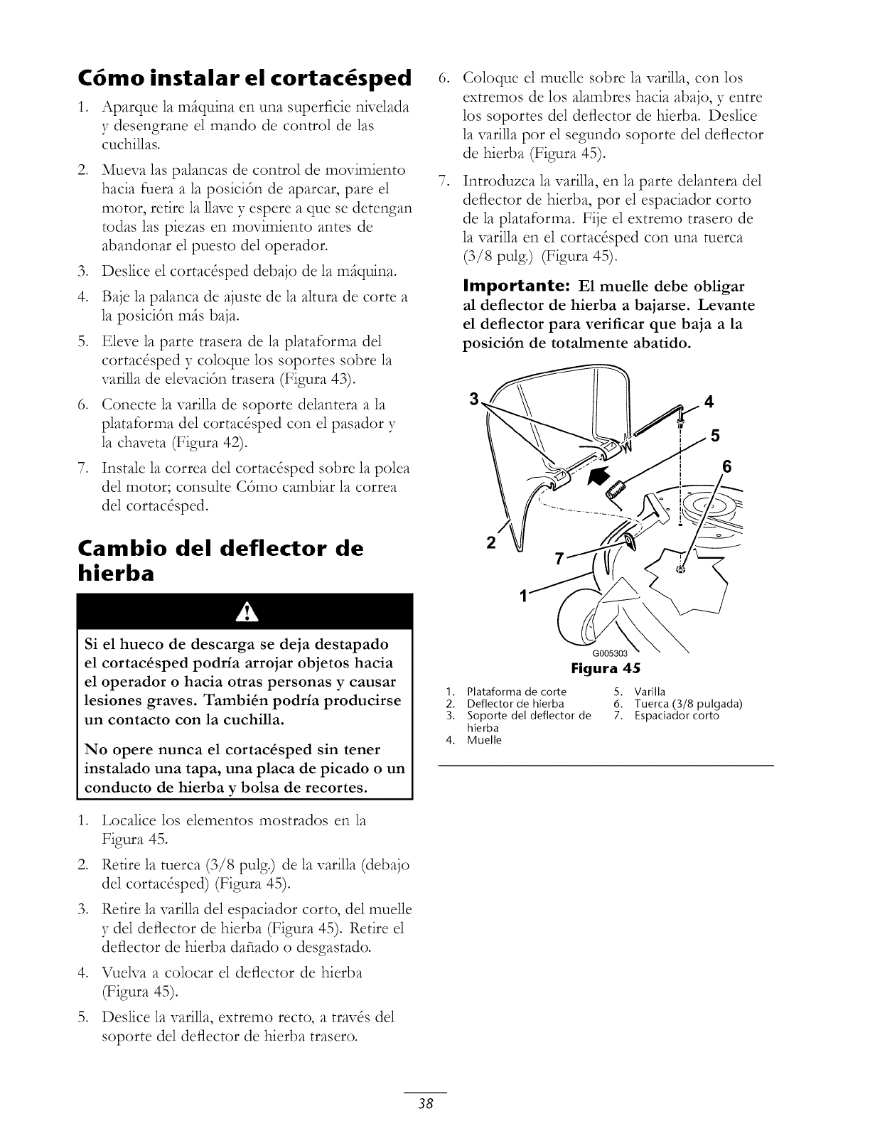
C6mo instalar el cortac6sped
1. Aparque la mfiquina en una superficie nk_elada
y desengrane el mando de control de las
cuchillas.
2. Mueva las palancas de control de movimiento
hacia fuera a la posicitn de aparcar, pare el
motor, retire la 1lave y espere a que se detengan
todas las piezas en movimiento antes de
abandonar el puesto del operador.
3. Deslice el cortac&ped debajo de la mfiquina.
4. Baje la palanca de ajuste de la altura de corte a
la posicitn mils baja.
5. Eleve la parte trasera de la plataforma del
cortac&ped y coloque los soportes sobre la
varilla de elevacitn trasera (Figura 43).
6. Conecte la varilla de soporte delantera a la
plataforma del cortac&ped con el pasador y
la chaveta (Figura 42).
7. Instale la correa del cortac&ped sobre la polea
del motor; consulte Cdmo cambiar la correa
del cortac&ped.
Cambio del deflector de
hierba
,
,
Coloque el muelle sobre la varilla, con los
extremos de los alambres hacia abajo, y entre
los soportes de1 deflector de hierba. Deslice
la varilla por el segundo soporte del deflector
de hierba (Figura 45).
Introduzca la varilla, en la parte delantera del
deflector de hierba, por el espaciador corto
de la plataforma. Fije el extremo trasero de
la varilla en el cortac&ped con una tuerca
(3/8 pulg.) (Figura 45).
Importante: E1 muelle debe obligar
al deflector de hierba a bajarse. Levante
el deflector para verificar que baja a la
posici6n de totalmente abatido.
2
Si el hueco de descarga se deja destapado
el cortac4sped podria arrojar objetos hacia
el operador o hacia otras personas y causar
lesiones graves. Tambi4n podria producirse
un contacto con la cuchilla.
No opere nunca el cortac_sped sin tener
instalado una tapa, una placa de picado o un
conducto de hierba y bolsa de recortes.
1. Localice los elementos mostrados en la
Figura 45.
2. Retire la tuerca (3/8 pulg.) de la varilla (debajo
de1 cortac&ped) (Figura 45).
3. Retire la varilla del espaciador corto, del muelle
y de1 deflector de hierba (Figura 45). Retire el
deflector de hierba dafiado o desgastado.
4. VueNa a colocar el deflector de hierba
(Figura 45).
5. Deslice la varilla, extremo recto, a trav& del
soporte del deflector de hierba trasero.
G005303
Figura 45
1. Plataforma de corte
2. Deflector de hierba
3. Soporte del deflector de
hierba
4. Muelle
5. Varilla
6. Tuerca (3/8 pulgada)
7. Espaciador corto
38
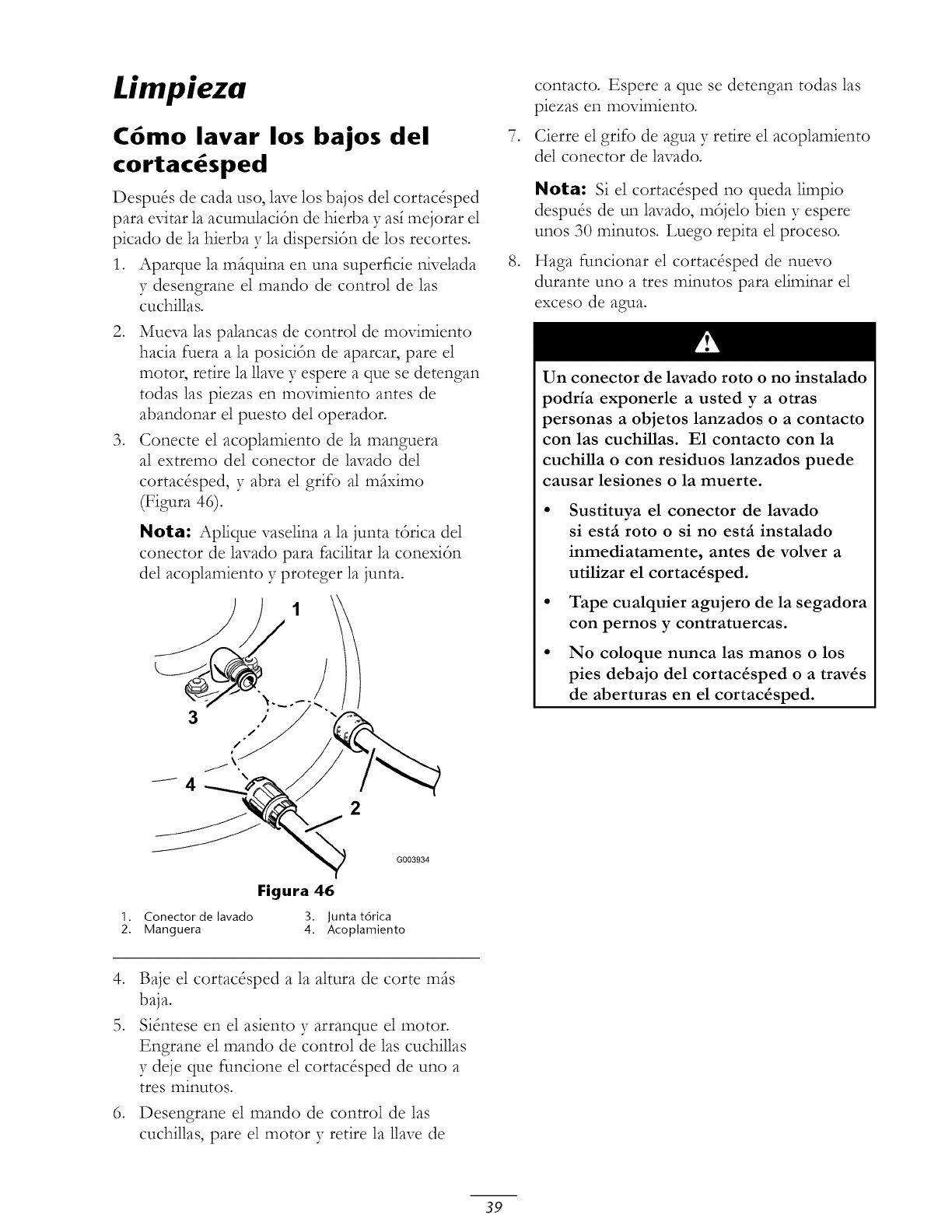
Limpieza
C6mo lavar los bajos del
cortac sped
Despu& de cada uso, lave los bajos del cortac&ped
para evitar la acumulaci6n de hierba y as_mejorar el
picado de la hierba y la dispersi6n de los recortes.
1. Aparque la miquina en una superficie nivelada
y desengrane el mando de control de las
cuchillas.
2. Mueva las palancas de control de movimiento
hacia fuera a la posici6n de aparcar, pare el
motor, retire la llave y espere a que se detengan
todas las piezas en movimiento antes de
abandonar el puesto del operador.
3. Conecte el acoplamiento de la manguera
al extremo del conector de lavado del
cortac&ped, y abra el grifo al miximo
(Figura 46).
Nota: Aplique vaselina a la junta t6rica del
conector de lavado para facilitar la conexi6n
del acoplamiento y proteger la junta.
2
,
,
contacto. Espere a que se detengan todas las
piezas en movimiento.
Cierre el grifo de agua y retire el acoplamiento
del conector de lavado.
Nota: Si el cortac&ped no queda limpio
despu& de un lavado, m6jelo bien y espere
unos 30 minutos. Luego repita el proceso.
Haga funcionar el cortac&ped de nuevo
durante uno a tres minutos para eliminar el
exceso de agua.
Un conector de lavado roto o no instalado
podria exponerle a usted y a otras
personas a objetos lanzados o a contacto
con las cuchillas. E1 contacto con la
cuchilla o con residuos lanzados puede
causar lesiones o la muerte.
• Sustituya el conector de lavado
si estai roto o si no estai instalado
inmediatamente, antes de volver a
utilizar el cortac4sped.
• Tape cualquier agujero de la segadora
con pernos y contratuercas.
• No coloque nunca las manos o los
pies debajo del cortac4sped o a trav4s
de aberturas en el cortac_sped.
1. Conector de lavado
2. Manguera
G003934
Figura 46
3. Junta t6rica
4. Acoplamiento
,
,
Baje el cortac&ped a la altura de corte mils
baja.
Si_ntese en el asiento y arranque el motor•
Engrane el mando de control de las cuchillas
y deje que funcione el cortac&ped de uno a
tres minutos.
Desengrane el mando de control de las
cuchillas, pare el motor y retire la llave de
39
Almacenamiento
Limpieza y almacenamiento
,
,
Desengrane el mando de control de las
cuchillas, mueva los controles de movimiento
hacia fuera a la posicitn de aparcar, pare el
motor y retire la llave.
Retire los recortes de hierba, la suciedad y
la mugre de las piezas externas de toda la
mSquina, especialmente el motor. Limpie
la suciedad y la broza de la parte exterior
del alojamiento de las aletas de la culata de
cilindros del motor y del soplador.
Importante: La m_iquina puede lavarse
con un detergente suave y agua. No lave la
m_iquina a presi6n. Evite el uso excesivo
de agua, especialmente cerca del panel de
control, el motor, las bombas hidniulicas y
los motores el_ctricos.
3. Revise el limpiador de aire; consulte
Mantenimiento de1 limpiador de aire en
Mantenimiento de1 motor, pfigina 26.
4. Engrase y lubrique la mfiquina; consulte
Lubricacidn, pfigina 25.
5. Cambie el aceite de1 critter y el filtro; consulte
Mantenimiento del aceite del motor, en
Mantenimiento del motor, pfigina 26.
6. Compruebe la presitn de los
neumfiticos; consulte Comprobacidn
de la presidn de los neumfiticos en
Mantenimiento del sistema de transmisidn,
pfigina 32.
7. Cargue la bateda; consulte Mantenimiento de la
bateda en Mantenimiento del sistema el&trico,
pfigina 30.
8. Compruebe la condicitn de las cuchillas;
consulte Mantenimiento de las cuchillas en
Mantenimiento del cortac&ped, pfigina 33.
9. Prepare la mfiquina para su almacenamiento
cuando no la vaya a utilizar durante m_s
de 30 d_as. Prepare la mfiquina para el
almacenamiento de la manera siguiente:
10. Agregue un estabilizador/acondicionador a
base de petrtleo al combustible del deptsito.
Siga las instrucciones de mezcla del fabricante
del estabilizador. No use un estabilizador a
base de alcohol (etanol o metanol).
11.
12.
13.
14.
15.
Nora: Un estabilizador/acondicionador
de combustible es m_s eficaz cuando se
mezcla con gasolina fresca y se utiliza en todo
momento.
Haga funcionar el motor para distribuir el
combustible con acondicionador por todo el
sistema de combustible (5 minutos).
Pare el motor, deje que se enfr_e, y drene
el depdsito de combustible; consulte
Drenaje del depdsito de combustible, en
Mantenimiento del sistema de combustible,
p_gina 30.
Vuelva a arrancar el motor y hfigalo funcionar
hasta que se pare.
Estrangule o cebe el motor. Arranque el
motor y dSjelo funcionar hasta que no vuelva
a arrancar. Use el cebador, si hay uno en la
m_quina, varias veces para asegurarse de que
no quede combustible en el sistema de cebado.
Deseche el combustible adecuadamente.
Recicle observando la normativa local.
Importante: No guarde la gasolina con
estabilizador/acondicionador durante m_is
de 30 dias.
Retire la(s) buj_a(s) y verifique su condicidn;
consulte Mantenimiento de la buj_a , en
Manteaimiento del motor, pfigina 26. Con
la(s) buj_a(s ) retirada(s) del motor, vierta dos
cucharadas soperas de aceite de motor en el
agujero de la buj_a. Utilice el motor de arranque
para hacer girar el motor y distribuir el aceite
dentro del cilindro. Instale la(s) buj_a(s). No
instale los cables en la(s) buj_a(s).
Limpie cualquier suciedad y recortes de encima
del cortac&ped.
Rasque cualquier acumulacidn importante de
hierba y suciedad de los bajos del cortac&ped,
luego lfivelo con una manguera de jard_n.
Compruebe la condicidn de las correas de
transmisidn y del cortac&ped.
Revise y apriete todos los pernos, tuercas y
tornillos. Repare o sustituya cualquier pieza
desgastada o dafiada.
40

16. Pinte las superficies que estOn arafiadas o
donde est8 visible el metal. Puede adquirir la
pintura en su Servicio T&nico Autorizado.
17. Guarde la mfiquina en un garaje o almacSn
seco y limpio. Retire la llave de contacto y
gufirdela en un lugar seguro que le sea fficil de
recordar. Cubra la mfiquina para protegerla y
para conservarla limpia.
41

Soluci6n de problemas
Problema Posible causa
El motor se sobrecalienta. 1. 1.
El motor de arranque no
gira.
.
3.
.
5.
La carga del motor es
excesiva.
El nivel de aceite del
c_rter est_ bajo.
Las aletas de
refrigeraci6n y los
conductos de aire
situados debajo del
alojamiento del soplador
del motor est_n
obstruidos.
El limpiador de aire est_
sucio.
Hay suciedad, agua o
combustible viejo en el
sistema de combustible.
1. El mando de control
de las cuchillas est_
engranado.
2. Las palancas de control
de movimiento no est_n
en la posici6n de aparcar.
3. El operador no est_
sentado.
4. La bateffa est_
descargada.
5. Las conexiones el_ctricas
est_n corro_das o sueltas.
6. Un fusible esta fundido.
7. Un rel_ o interruptor est_
daffado.
.
3.
Acci6n correctora
Reduzca la velocidad
sobre el terreno.
Affada aceite al c_rter.
Elimine la obstrucci6n de
las aletas de refrigeraci6n
y de los conductos de
aire.
4. Limpie o cambie el filtro
del limpiador de aire.
5. P6ngase en contacto
con el Servicio T6cnico
Autorizado.
.
.
.
4.
5.
.
7.
Mueva el mando de
control de las cuchillas a
Desengranado.
Mueva las palancas de
control de movimiento
hacia fuera a la posici6n
de aparcar.
Si6ntese en el asiento.
Cargue la bateffa.
Verifique que hay
buen contacto en las
conexiones el6ctricas.
Cambie el fusible.
P6ngase en contacto
con el Servicio T6cnico
Autorizado.
42
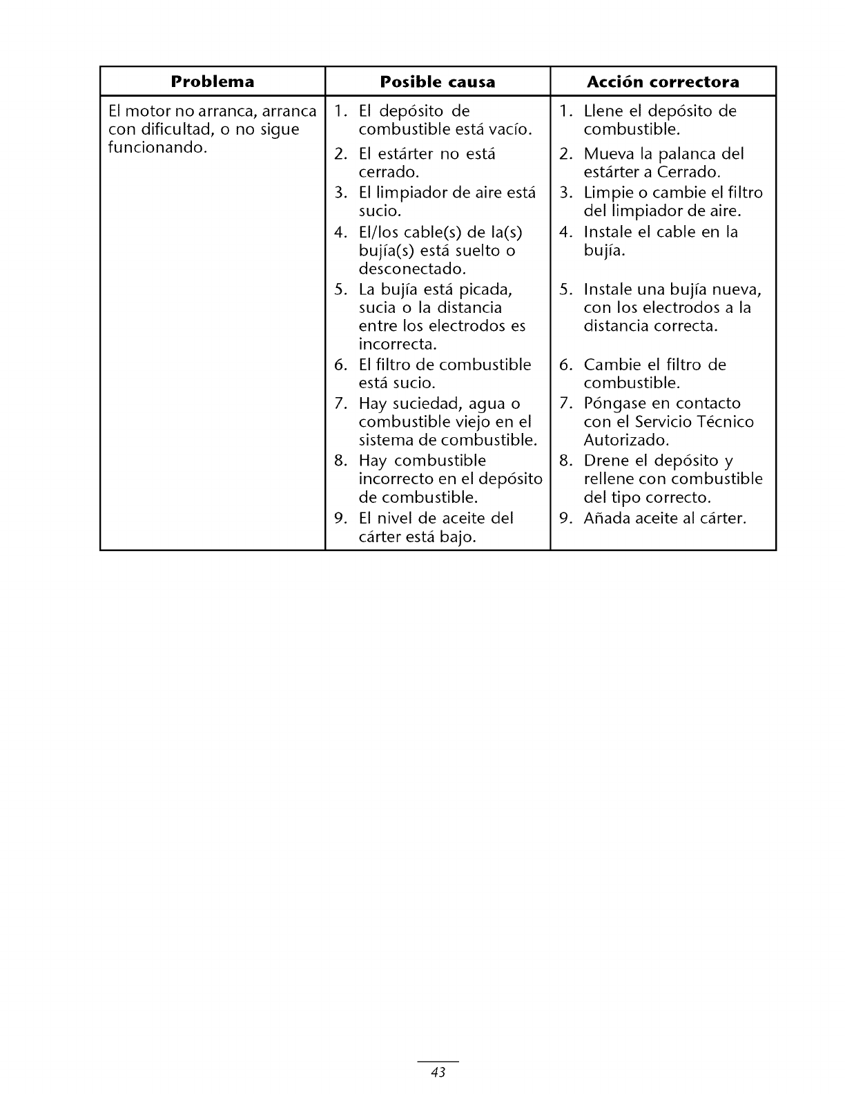
Problema
El motor no arranca, arranca
con dificultad, o no sigue
funcionando.
I .
2.
3.
4.
.
.
7.
.
.
Posible causa Acci6n correctora
El dep6sito de
combustible est_ vac_o.
El est_rter no est_
cerrado.
El limpiador de aire est_
sucio.
El/los cable(s) de la(s)
buj[a(s) est_ suelto o
desconectado.
La buj_a est_ picada,
sucia o la distancia
entre los electrodos es
incorrecta.
El filtro de combustible
est_ sucio.
Hay suciedad, agua o
combustible viejo en el
sistema de combustible.
Hay combustible
incorrecto en el dep6sito
de combustible.
El nivel de aceite del
c_rter est_ bajo.
I .
2.
3.
4.
.
Llene el dep6sito de
combustible.
Mueva la palanca del
est_rter a Cerrado.
Limpie o cambie el filtro
del limpiador de aire.
Instale el cable en la
buj_a.
Instale una buj_a nueva,
con los electrodos a la
distancia correcta.
6. Cambie el filtro de
combustible.
7. P6ngase en contacto
con el Servicio T6cnico
Autorizado.
8. Drene el dep6sito y
rellene con combustible
del tipo correcto.
9. Affada aceite al c_rter.
43
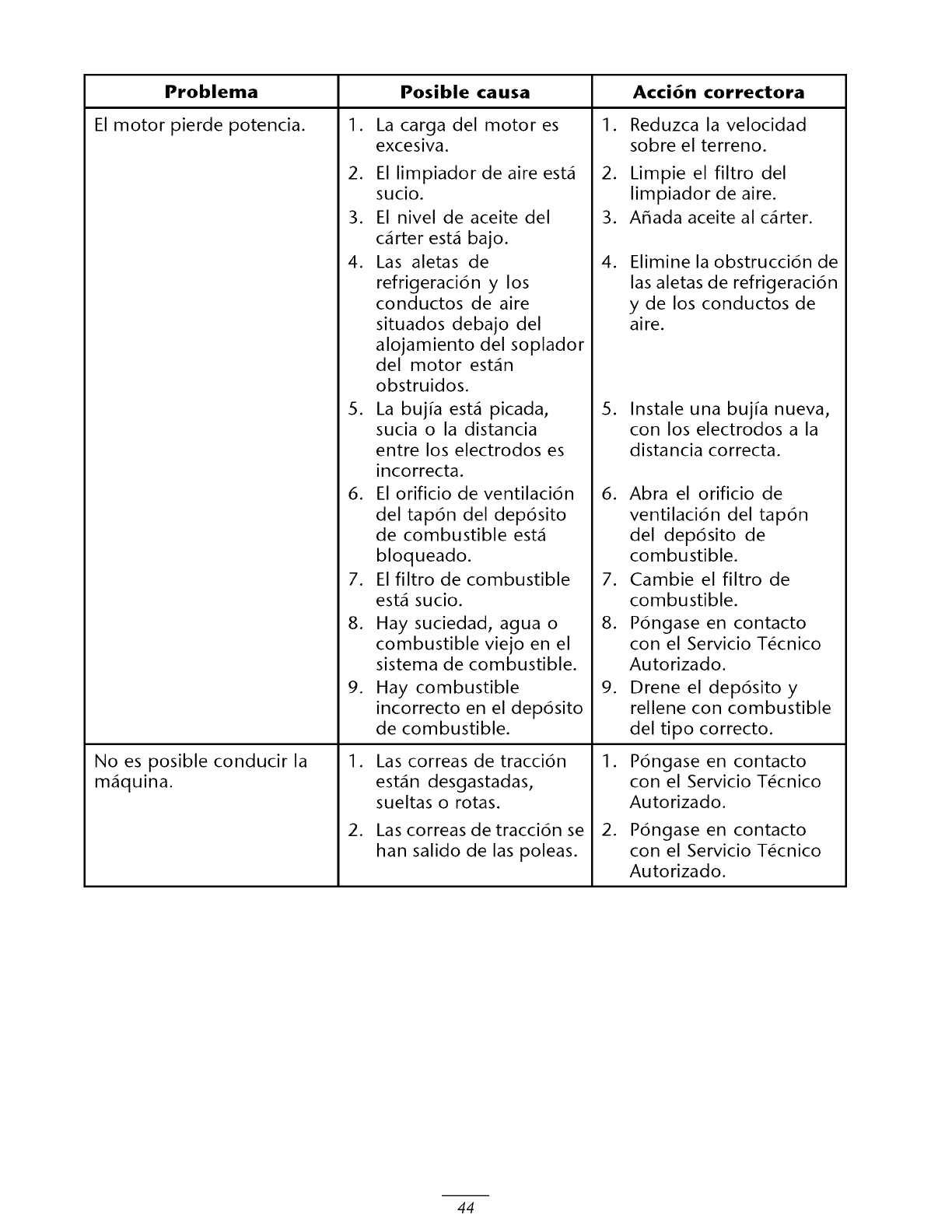
Problema
El motor pierde potencia.
Posible causa
1. 1.
La carga del motor es
excesiva.
2. El limpiador de aire est_
sucio.
3. El nivel de aceite del
.
3.
Acci6n correctora
Reduzca la velocidad
sobre el terreno.
Limpie el filtro del
limpiador de aire.
A_ada aceite al c_rter.
.
c_rter est_ bajo.
Las aletas de
refrigeraci6n y los
conductos de aire
situados debajo del
.Elimine la obstrucci6n de
las aletas de refrigeraci6n
y de los conductos de
aire.
No es posible conducir la
m_quina.
.
.
.
8.
.
alojamiento del soplador
del motor est_n
obstruidos.
La buj[a est_ picada,
sucia o la distancia
entre los electrodos es
incorrecta.
El orificio de ventilaci6n
del tap6n del dep6sito
de combustible est_
bloqueado.
El filtro de combustible
est_ sucio.
Hay suciedad, agua o
combustible viejo en el
sistema de combustible.
Hay combustible
incorrecto en el dep6sito
de combustible.
1. Las correas de tracci6n
est_n desgastadas,
sueltas o rotas.
2. Las correas de tracci6n se
han salido de las poleas.
5. Instale una buj[a nueva,
con los electrodos a la
distancia correcta.
.
.
8.
.
Abra el orificio de
ventilaci6n del tap6n
del dep6sito de
combustible.
Cambie el filtro de
combustible.
P6ngase en contacto
con el Servicio T6cnico
Autorizado.
Drene el dep6sito y
rellene con combustible
del tipo correcto.
1. P6ngase en contacto
con el Servicio T6cnico
Autorizado.
2. P6ngase en contacto
con el Servicio T6cnico
Autorizado.
44
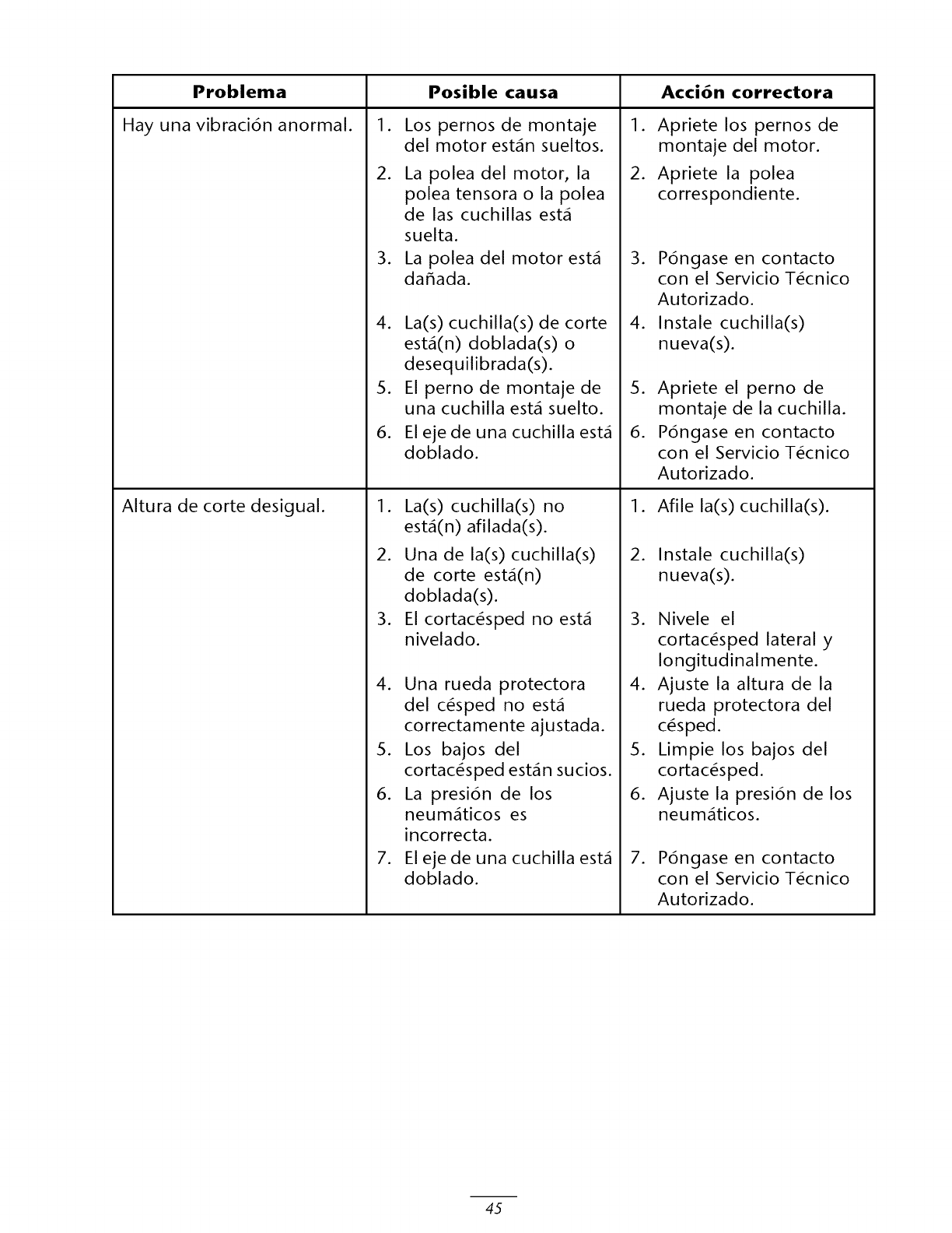
Problema
Hay una vibraci6n anormal.
Altura de corte desigual.
Posible causa Acci6n correctora
1. 1.
.
Los pernos de montaje
del motor est_n sueltos.
La polea del motor, la
polea tensora o la polea
de las cuchillas est_
suelta.
3. La polea del motor est_
da_ada.
4. La(s) cuchilla(s) de corte
est,(n) doblada(s) o
desequilibrada(s).
5. El perno de montaje de
una cuchilla est_ suelto.
6. El ejede una cuchilla est_
doblado.
1. La(s) cuchilla(s) no
est,(n) afilada(s).
2. Una de la(s) cuchilla(s)
de corte est,(n)
doblada(s).
3. El cortac_sped no est_
nivelado.
4. Una rueda protectora
del c_sped no est_
correctamente ajustada.
5. Los bajos del
cortac_sped est_n sucios.
6. La presi6n de los
neum_ticos es
incorrecta.
.El ejede una cuchilla est_
doblado.
.
.
Apriete los pernos de
montaje del motor.
Apriete la polea
correspondiente.
P6ngase en contacto
con el Servicio T_cnico
Autorizado.
4. Instale cuchilla(s)
nueva(s).
5. Apriete el perno de
montaje de la cuchilla.
6. P6ngase en contacto
con el Servicio T_cnico
Autorizado.
1. Afile la(s) cuchilla(s).
2. Instale cuchilla(s)
nueva(s).
3. Nivele el
cortac_sped lateral y
Iongitudinalmente.
4. Ajuste la altura de la
rueda protectora del
c_sped.
5. Limpie los bajos del
cortac_sped.
6. Ajuste la presi6n de los
neum_ticos.
.P6ngase en contacto
con el Servicio T_cnico
Autorizado.
45
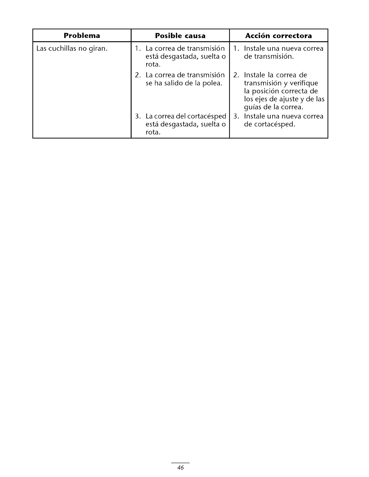
Problema
Las cuchillas no giran.
Posible causa
1. 1.
.
.
La correa de transmisi6n
est_ desgastada, suelta o
rota.
La correa de transmisi6n
se ha salido de la polea.
La correa del cortac_sped
est_ desgastada, suelta o
rota.
Acci6n correctora
Instale una nueva correa
de transmisi6n.
2. Instale la correa de
transmisi6n y verifique
la posici6n correcta de
los ejes de ajuste y de las
gu_as de la correa.
3. Instale una nueva correa
de cortac_sped.
46
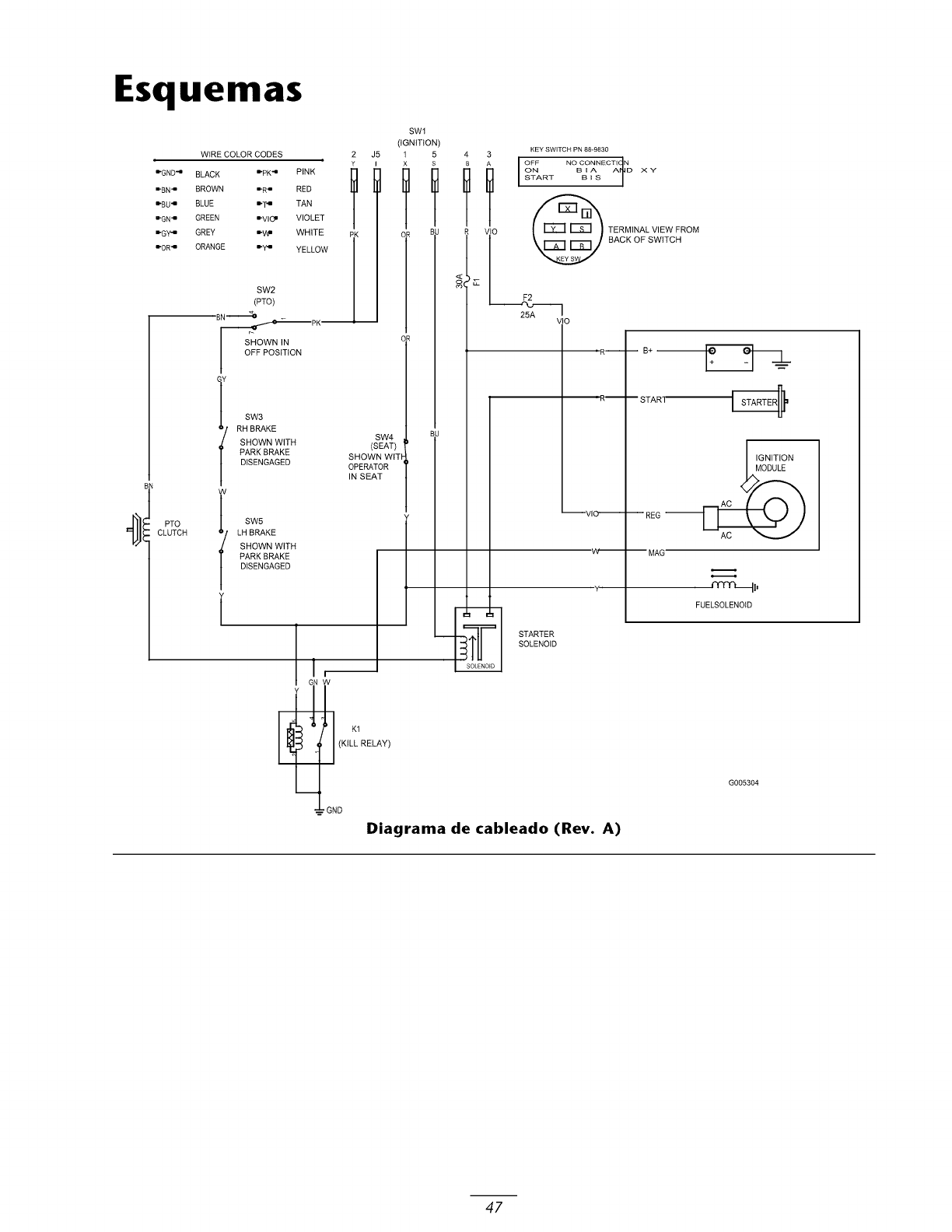
Esquemas
WIRE COLOR CODES 2 J5
_GND4 BLACK _pK 4 PINK []
_BN 4 BROWN _R _ RED
_BU 4 BLUE _T _ TAN
_GN _ GREEN _VlO m VIOLET
_Gy_ GREY _VW WHITE PK
_OR _ ORANGE _y4 YELLOW
SW2 I
(PTO) I
8N _____,_OmpK'_
SHOWN IN
OFF POSiTiON
SW3
RH BRAKE
SW4
SHOWN WITH (SEAT)
PARK BRAKE SHOWN WIT
DISENGAGED OPERATOR
IN SEAT
l SW5
LH BRAKE
SHOWN WITH
PARKBRAKE
DISENGAGED
NW
(KILL RELAY)
-- GND
SWl
(iGNiTiON)
1 5
TT
',v
KEY SWITCH PN 88-9830
NO GONNEGTI N
ON B D XY
START
_ ERMINAL VIEW FROM
BACK OF SWITCH
F2
25A /10
Y
STARTER
SOLENOID
_REG
-- MAG"
IGNITION
ODULE
._.._.
FUELSOLENOID
G005304
Diagrama de cableado (Rev. A)
47
Declaraci6n de garantia de control de emi-
siones evaporativas
Declaracion de garantfa de control de emisiones evaporativas de
California - Sus derechos yobligaciones bajo la garantfa
Introducci6n
La Junta de Recursos del Aire de California (California Air Resources Board) y The Toro ®Company tienen mucho gusto en explicar
la garant[a del sistema de control de emisiones evaporativas de su equipo del a_o 2006. En California, los equipos nuevos que
utilizan peque_os motores para uso fuera de la via pL_blica deben ser dise_ados, fabricados y equipados segL_n la estricta normativa
anticontaminaci6n del Estado. The Toro ®Company debe garantizar el sistema de control de emisiones evaporativas de su equipo
durante dos a_os, siempre que su equipo no haya estado sometido a uso incorrecto, negligencia o mantenimiento inapropiado.
Su sistema de control de emisiones evaporativas puede incluir piezas tales como: tubos de combustible, herrajes para tubos de
combustible y abrazaderas.
Cobertura de garantia del fabricante:
Este sistema de control de emisiones evaporativas esta garantizado durante dos a_os. Si cualquier pieza de su equipo relacionada con
emisiones evaporativas est_ defectuosa, la pieza ser_ reparada o sustituida por The Toro ®Company.
Responsabilidades del propietario bajo la garantia:
•Como propietario del equipo, usted es responsable de la realizaci6n del mantenimiento requerido relacionado en su Manual del
operador. The Toro ® Company recomienda que usted guarde todos los recibos relacionados con el mantenimiento de su equipo,
pero The Toro _°_Company no puede negarle cobertura bajo la garant[a L_nicamente por falta de recibos.
• Como propietario del equipo, usted debe saber que The Toro _°_Company puede negarle cobertura bajo la garant[a si las piezas
cubiertas por la garant[a de emisiones han fallado debido a abuso, negligencia, mantenimiento inapropiado o modificaciones no
autorizadas.
• Usted es responsable de llevar su equipo a un Servicio T_cnico Autorizado tan pronto como se produzca un problema. Las
reparaciones bajo garant[a deben completarse en un plazo razonable, que no superar_ los 30 d[as. Si usted tiene alguna pregunta
sobre la cobertura de la garant[a, p6ngase en contacto con The Toro ® Company en el 1-952-948-4027 o ll_menos al tel_fono
gratuito que figura en su Declaraci6n de garant[a Toro.
I.
2.
3.
Defectos - Requisitos de la garantia:
El periodo de la garant[a empieza en la fecha en que el motor o el equipo es entregado a un comprador final.
Cobertura de la Garant[a general de emisiones evaporativas. Respecto alas piezas cubiertas por la garant[a de emisiones, al
comprador L_Itimo ya cualquier propietario posterior se le debe garantizar que el sistema de control de emisiones evaporativas, en
el momento de su instalaci6n:
A. Estaba dise_ado, fabricado yequipado para cumplir toda la normativa aplicable, y
B. Estaba libre de defectos en materiales ymano de obra que pudieran provocar el fallo de una pieza garantizada en un periodo
de dos a_os.
La garant[a sobre piezas relacionadas con emisiones evaporativas ser_ interpretada de la siguiente manera:
A. Cualquier pieza garantizada cuya sustituci6n como parte del mantenimiento necesario no est_ prevista en las instrucciones
escritas debe estar garantizada por el periodo de garant[a de dos a_os. Si una pieza de las descritas falla durante el periodo
de cobertura de garant[a, debe ser reparada o sustituida por The Toro ® Company. Cualquier pieza de las descritas que sea
reparada o sustituida bajo la garant[a debe quedar garantizada durante un periodo no inferior al periodo de garant[a restante.
B. Cualquier pieza garantizada que tenga prevista en las instrucciones escritas L_nicamente la inspecci6n regular debe estar
garantizada por el periodo de garant[a de dos afios. Cualquier instrucci6n similar a "reparar o sustituir segL_n sea necesario"
en dichas instrucciones escritas no reducir_ el periodo de cobertura de la garant[a. Cualquier pieza de las descritas que sea
reparada o sustituida bajo garant[a debe quedar garantizada durante un periodo no inferior al periodo de garant[a restante.
C. Cualquier pieza garantizada cuya sustituci6n est_ prevista como mantenimiento necesario en las instrucciones escritas debe
estar garantizada durante el periodo de tiempo restante hasta la primera sustituci6n programada de dicha pieza. Si la pieza
falla durante el periodo de cobertura de garant[a, la pieza debe ser reparada o sustituida por The Toro ®Company. Cualquier
pieza de las descritas que sea reparada o sustituida bajo garant[a debe quedar garantizada durante un periodo no inferior al
periodo de tiempo restante hasta la primera sustituci6n programada de dicha pieza.
D. La reparaci6n o sustituci6n de cualquier pieza garantizada bajo las provisiones de garant[a de este apartado debe ser realizada
sin coste para el propietario en un Servicio T_cnico Autorizado.
E. No obstante las provisiones de la subsecci6n (D) anterior, los servicios o reparaciones realizados bajo la garant[a deben ser
prestados o realizados en un Servicio T_cnico Autorizado.
F. No se har_ ningL_n cargo al propietario por trabajos de diagn6stico que lleven a la determinaci6n de que una pieza garantizada
est_ defectuosa, si los trabajos de diagn6stico se realizan en un Servicio T_cnico Autorizado.
G. Durante todo el periodo de garant[a de dos a_os del sistema de control de emisiones evaporativas, The Toro ®Company debe
mantener un suministro de piezas garantizadas suficiente para satisfacer la demanda prevista de dichas piezas.
H. Para la realizaci6n de cualquier tarea de mantenimiento o reparaci6n bajo la garant[a, deben utilizarse piezas de repuesto
homologadas por el fabricante, y_stas deben proporcionarse sin coste para el propietario. Dicho uso no reducir_ las
obligaciones de The Toro ® Company bajo la garant[a.
I. El uso de piezas a_adidas o modificadas puede constituir raz6n suficiente para la negaci6n de una reclamaci6n bajo la garant[a
hecha con arreglo a este apartado. The Toro _°_Company no ser_ responsable bajo este Apartado de cubrir fallos de piezas
garantizadas causados por el uso de piezas a_adidas o modificadas.
]. The Toro _°_Company proporcionar_ cualesquier documentos que describan los procedimientos o las pol[ticas de garant[a
en el plazo de cinco d[as laborables si la Junta de Recursos del Aire los solicita.
374-0092 Rev A

Declaraci6n de garantia de control de emi-
siones evaporativas
Declaracion de garantfa de control de emisiones evaporativas de
California - Sus derechos yobligaciones bajo la garantfa
Lista de piezas cubiertas pot la garantia de emisiones:
La lista siguiente incluye las piezas cubiertas bajo esta garant_a:
• Tubos de combustible
• Herrajes de los tubos de combustible
• Enganches
374-0092 Rev A
Cortac_s-
pedesde
consumoTi-
meCutterZ
yZX
La Garantia Toro de cobertura total
Una garantfa limitada de tres a_os (Garantfa limitada
para el uso comercial)
Condiciones y productos cubiertos
The Toro Company y su afiliado, Toro Warranty Company, bajo
un acuerdo entre s_,prometen conjuntamente al comprador
original* reparar cualquier producto Toro usado con prop6sitos
residenciales normales* si tiene defectos de materiales o mano
de obra. Los siguientes plazos son aplicables desde la fecha de
la compra:
Productos
Todos los cortac_spedes
y accesorios TimeCutter Z
Todos los cortac_spedes y
accesorios TimeCutter ZX
(Modelos 74812 y74814)
Periodo de garant_a
Garant_a limitada de 3 a_os
Garant_a limitada de 3 a_os
Todas las bateffas Garant[a limitada de I a_o
Esta garant[a incluye el coste de piezas ymano de obra, pero
usted debe pagar los costes de transporte a ydesde el servicio
t_cnico.
Esta garant[a es aplicable a todos los cortac_spedes yaccesorios
TimeCutter Z yTimeCutter ZX (Modelos 74812 y 74814).
*"Prop6sito residencial normal" significa el uso del producto en
la misma parcela en que se encuentra su vivienda. El uso en m_s
de un lugar se considera uso comercial, yno existe garant[a de
uso comercial.
Garantia Iimitada para el uso comercial
Los productos de consumo yaccesorios Toro utilizados con
prop6sitos comerciales, institucionales o de alquiler est_n
garantizados contra defectos en materiales o mano de obra
durante los periodos de tiempo siguientes a partir de su fecha
de compra:
Productos
Motores de gasolina
refrigerados por aire
Todos los demos art[culos
Periodo de garant[a
Garant[a limitada de 90 d[as
Garant[a limitada de 30 d[as
Instrucciones para obtener asistencia bajo la
garantia
Si usted cree que su producto Toro tiene un defecto de materiales
o de mano de obra, siga este procedimiento:
I. P6ngase en contacto con cualquier Distribuidor Autorizado
o Distribuidor Master Service de Toro para concertar el
mantenimiento en sus instalaciones. Para localizar un
distribuidor cerca de usted, consulte las P_ginas Amarillas
telef6nicas (mire en "cortac_spedes") o visite nuestro sitio
web en www.Toro.com. Los clientes de EE.UU. pueden
tambi_n llamar al nLimero gratuito 866-834-9033 para usar
nuestro sistema de localizaci6n de distribuidores las 24 horas
al d[a.
2. Lleve el producto ysu prueba de compra (recibo o factura de
venta) al Distribuidor.
Si por alguna raz6n usted no est_ satisfecho con el an_lisis del
Distribuidor o con la asistencia recibida, p6ngase en contacto con
nosotros en la direcci6n siguiente:
Customer Care Department, Consumer Division
Toro Warranty Company
8111 Lyndale Avenue South
Bloomington, MN 55420-I 196
Tel_fono gratuito: 866-216-6029 (clientes de EE.UU.)
Tel_fono gratuito: 866-216-6030 (clientes de Canada)
Responsabilidades del propietario
Usted debe mantener su Producto Toro siguiendo los
procedimientos de mantenimiento descritos en el Manual del
operador. Dicho mantenimiento rutinario, sea realizado por un
distribuidor o por usted mismo, es por cuenta de usted.
Elementos y condiciones no cubiertos
No hay otra garant[a expresa salvo la cobertura especial de
sistemas de emisi6n en algunos productos. Esta garant[a expresa
no cubre:
•El coste del mantenimiento regular o de las piezas, tales como
filtros, combustible, lubricantes, piezas de puesta a punto,
afilado de cuchillas, ajustes de frenos yembragues.
• Cualquier producto o pieza que haya sido modificado
o real utilizado o que haya necesitado ser sustituido o
reparado debido a desgaste normal, accidente o falta de
mantenimiento adecuado.
• Las reparaciones necesarias debidas al uso del combustible
incorrecto, contaminantes en el sistema de combustible o
falta de preparaci6n adecuada del sistema de combustible
antes de cualquier periodo de inactividad de m_s de tres
meses.
• Costes de recogida y entrega a y desde un Servicio T_cnico
Autorizado de Toro.
Condiciones generales
Todas las reparaciones cubiertas por esta garant_a deben ser
realizadas por un Servicio T_cnico Autorizado de Toro usando
piezas de repuesto homologadas por Toro.
La reparaci6n pot un Servicio T_cnico Autorizado de
Toro es su ,_nico remedio bajo esta garantla.
Ni The Toro Company ni Toro Warranty Company
son responsables de da_os directos, indirectos o
consecuentes en conexi6n con el uso de los productos
Toro cubiertos por esta garantla, incluyendo cualquier
coste o gasto por la provisi6n de equipos de sustituci6n
o servicio durante periodos razonables de mal
funcionamiento o no utilizaci6n hasta la terminaci6n de
reparaciones bajo esta garantla.
Algunos estados no permiten exclusiones de da_os
incidentales o consecuentes, de manera que las
exclusiones y limitaciones arriba citadas pueden no ser
aplicables a usted.
Esta garantla le otorga a usted derechos legales
especfficos; es posible que usted tenga otros derechos
que varlan de un estado a otto.
Paises fuera de Estados Unidos o Canad_
Los clientes que compraron productos Toro exportados de los Estados Unidos o Canad_ deben ponerse en contacto con su Distribuidor
Toro para obtener p61izas de garant[a para su pals, provincia o estado. Si por cualquier raz6n usted no est_ satisfecho con el servicio
ofrecido por su distribuidor, o si tiene dificultad en obtener informaci6n sobre la garant[a, p6ngase en contacto con el importador Toro.
Si fallan todos los demos recursos, puede ponerse en contacto con nosotros en Toro Warranty Company
374-01 24 Rev A
