Toro SCG Light Logic Plus LPlus /SMRT Logic SMRT-T SMRT-I User Manual SCG Unique v1 1
Toro Company Light Logic Plus LPlus /SMRT Logic SMRT-T SMRT-I SCG Unique v1 1
Toro >
Contents
- 1. Irritrol User Manual
- 2. Toro User Manual
- 3. Unique User Manual
Unique User Manual
Register Add a Location
12
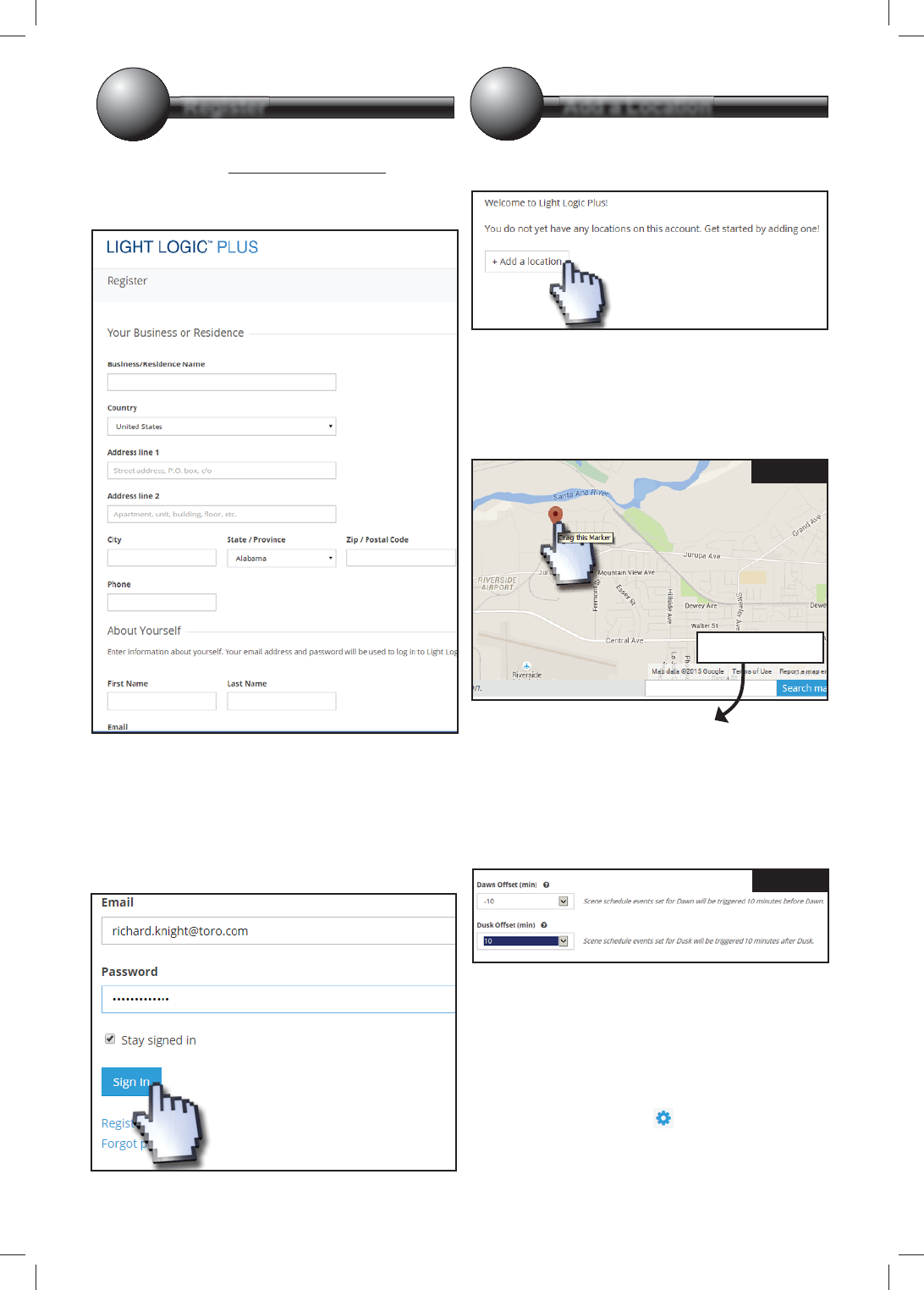
Light Logic PLUS account must be set up.
1. Point browser to www.lightlogicplus.com.
2. Click the Register link.
3. Fill out all elds and press Register.
4. A verication link will be e-mailed to the specied
e-mail address. Click the verication link in
the e-mail. You will be taken to the Light Logic
website. Click the Complete Registration link.
5. You will be taken to the sign in page.
Enter e-mail address and password
then click Sign In.
Now we need to add the location of the
Light Logic PLUS.
1. Click + Add a Location.
2. Fill out the Name and Description elds. For
example, “Home” and “Primary residence”
respectively.
3. On the Google Maps map (Figure 1), enter
desired address into the Address eld or drag the
location of the red arrow to the desired location.
4. Scroll down. Enter a PIN for the Light Logic
PLUS to enable manual operation. PIN must
match the PIN of the Remote (LMRT) if a remote
is owned.
5. Enter a value (ranging from -120 minutes to 120
minutes) for the Dawn and Dusk Osets (Figure
2). A negative oset will be earlier than the
calculated dusk/dawn; a positive oset will be later.
6. Click Submit.
Add a Second Location
It is possible to add another location: a vacation
house for example. Repeat steps 1-7 above with a new
Name.
Edit a Location
1. Click the blue gear icon to the right of the
location name.
2. A contextual menu appears. Select Edit Location.
3. Follow steps 2-7 as above.
Figure 1
Figure 2
Light Logic Plus User Manual Model: LPlus
Add Scene/s Add Hardware
34
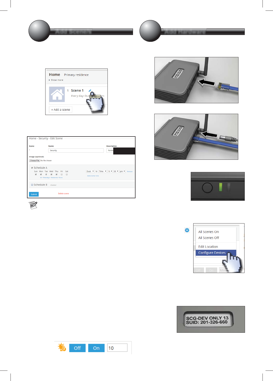
After adding a location, a default Scene is
added to the Light Logic. e default scene
turns on every day of the week from Dusk to 10pm.
To edit the Scene:
1. Click the blue pen by “Scene 1” text.
2. Change the Scene name, description, which days
of the week the scene will execute, and the times of
operation for the specied days as desired.
As you can see in Figure 3, it is possible to have
two dierent Schedules (A and B) for each scene.
For example, one might want security lights to
stay on longer on Friday and Saturday nights.
3. Click Submit.
Add a Scene
It is possible to add additional scenes to the Light
Logic PLUS (see cover diagram).
1. Click the + Add a Scene button.
2. Enter a name, description, specify the days of the
week to run and the time for those days.
Add a Schedule B if desired.
3. Click Create Scene.
1. Press the blue pen next to the Scene name.
2. Click the red Delete scene link (Figure 3).
Conrm.
To manually turn on or o a scene:
Click the On or O button to the right of the scene.
To run a scene for a specic length of time, enter the
desired time (in minutes) then press On.
Connecting the Light Logic PLUS
1. Connect Ethernet cable from internet router to
RJ45 port on back of PLUS.
2. Plug in the AC adapter.
3. PLUS lights ash. Left LED should eventually
settle on solid green.
Now we have to add the Light Logic PLUS to your
Light Logic account.
1. At the computer, click
the blue gear icon
by the location to add
the PLUS. From the
contextual menu,
select Congure
Devices.
2. Type in the Light Logic PLUS ID. is is the
“SUID” number on the sticker on the bottom of
the unit.
3. Enter the Security key also found on bottom.
Click Submit.
4. e PLUS
should be
added to the
system.
Figure 3
Position Antenna and
Unit as Shown.
Use Supplied
A
ntenna Only
Problem Cause Solution
LED remains orange Light Logic PLUS unable to get an IP
address from the network’s DHCP server. assign IP addresses. If needed, an LLP
static IP address. Refer to Advanced LLP
network setup on the website.
LED blinks green LLP unable to reach the internet.
connection using the same Ethernet wire
if possible.
Troubleshooting
Support
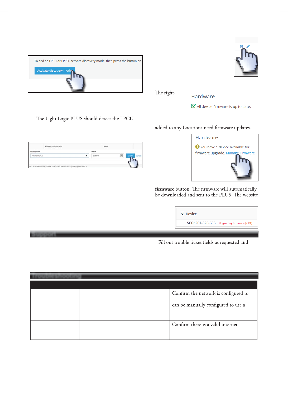
Add LPCUs to the PLUS
We need to add LPCUs at this time. LPCUs must be
added one at a time.
1. Press the Activate discovery mode button.
2. You will be prompted to press the button on the
LPCU to add. Go to the LPCU and press the
button.
3.
Give the detected LPCU a description and assign
it to the desired scene.
4. Press the Submit button when done.
5. Repeat steps 1-4 for each LPCU to add.
Edit Light Logic Equipment
Mouse-click the blue pencil icon to
edit LPCU description or change scene
assignment.
Delete Light Logic Equipment
Mouse-click the blue trashcan icon to
delete a LPCU.
Update the Firmware
1. Go to Accounts and select desired account.
2.
hand side
of the Light
Logic PLUS
window will
show if any of the Light Logic PLUS equipment
3. If an update is
available, press
the Manage
Firmware link.
4. You will see a
list of devices
that can be
upgraded. Press
the Upgrade
displays the progress of the update.
1. Click the Contact button at the bottom of the
page.
2. On the right side of the page, click the Submit a
ticket link.
3.
click the Create Ticket button.
4. It is also possible to check ticket status here by
clicking Check Ticket Status at the top of the
page.
FCC Statement and Caution - FCC ID: OF7SCG
This device complies with Part 15 of the FCC Rules. Operation is subject to the following two conditions: (1) This device
may not cause harmful interference, and (2) this device must accept any interference received, including interference that
may cause undesired operation.
In order to maintain compliance with the FCC RF exposure guidelines, this device should be installed and operated with a
minimum distance of 20cm between the radiator, and the body of the operator and/or nearby persons.
Any change or modification not approved by the party responsible for compliance could void the user’s authority to operate
this device.
Permit
ted Low Gain Dipole Whip Antenna (2dBi).
IC Statement
- IC: 3575A-SCG
1.
Under Industry Canada
regulations, this radio transmitter may only operate using an antenna of a type and maximum
(or lesser) gain approved for the transmitter by Industry Canada. To reduce potential radio interference to other users, the
antenna type and its gain should be so
chosen that the equivalent isotropically radiated power (e.i.r.p.) is not more than that
necessary for successful communication.
Conformément à la réglementation d'Industrie Canada, le présent émetteur radio peut fonctionner avec une
antenne d'un type et d'un gain maximal (ou inférieur) approuvé pour
l'émetteur par Industrie Canada. Dans le but de réduire les risques de brouillage radioélectrique à l'intention des
autres utilisateurs, il faut choisir le type d'antenne et son gain de sorte que la puissance isotrope rayonnée
équivalente (p.i.r.e.) ne dépasse pas l'intensité nécessaire à l'établissement d'une communication satisfaisante.
This radio transmitter has been approved by Industry Canada to operate with the antenna types listed below with the
maximum permissible gain and required antenna impedance for each antenna type indicated. Antenna types not included in
this list, having a gain greater than the maximum gain indicated for that type, are strictly prohibited for use with this dev
ice.
Le prés
ent émetteur radio (identifier le dispositif par son numéro de certification ou son numéro de modèle s'il fait
partie du matériel de catégorie I) a été approuvé par Industrie Canada pour fonctionner avec les types d'antenne
énumérés ci-dessous et ayant un gain admissible maximal et l'impédance requise pour chaque type d'antenne.
Les types d'antenne non inclus dans cette liste, ou dont le gain est supérieur au gain maximal indiqué, sont
strictement interdits pour l'exploitation de l'émetteur.
Antenna Approved/Antenne approuvé
Type/Type
Max. Gain/Max. Gain
Impedance/Impédance
Dipole Whip
2.0 dBi
50 Ω
This device complies with Industry Canada
licence-exempt RSS standard(s). Operation is subject to the following two conditions: (1)
this device may not cause interference, and (2) this device must accept any interference, including interference that may cau
se
undesired operation of the device.
Le présent appareil est conforme aux CNR d'Industrie Canada applicables aux appareils radio exempts de licence.
L'exploitation est autorisée aux deux conditions suivantes : (1) l'appareil ne doit pas produire de brouillage, et (2)
l'utilisateur de l'appareil doit accepter tout brouillage radioélectrique subi, même si le brouillage est susceptible d'en
compromettre le fonctionnement.
In order to maintain compliance with the IC RF exposure guidelines, this device should be installed and operated with a mi
nimum
distance of 20 cm between the radiator, and the body of the operator and/or nearby persons.
Afin de maintenir la conformité avec les directives d'exposition RF IC, ce dispositif doit être installé et exploité avec une
distance minimale de
20 cm entre le radiateur et le corps de l'opérateur ou à proximité de personnes.