Toshiba Client Solutions PL5080WL Libretto User Manual Manual 2of7
Toshiba Corporation Libretto Manual 2of7
Contents
Manual 2of7
96
1. PRODUCT SPECIFICATIONS
Specifications for Wireless LAN Functions
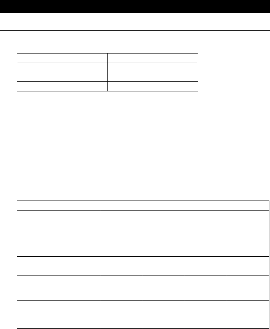
! Physical specifications
Power save (doze) mode 45 mA
Receive mode 250 mA
Send mode 350 mA
Power 3.3 V
! Wireless features
The wireless features of the wireless LAN vary depending on the product you purchase and the
country you are in when you purchase it.
I many cases, the wireless transmission are based on the wireless regulations of the country
where it is being used. Wireless network equipment is designed to use 2.4 GHz bandwidth to
operate which does not require a wireless license. However, depending on the national wireless
regulations, there may be several restrictions on the use of wireless network equipment.
NOTE:•See the “Users Announcement” for information on the appropriate wireless
regulations for each country.
Wireless frequency range 2.4 GHz (2400 to 2483.5 MHz)
Modulator
Direct diffusion format
CCK (Forwarding rate; High, Medium)
DQPSK (Forwarding rate; Standard)
DBPSK (Forwarding rate; Low)
Diffusion format 11 chip Barker Sequence
Bit error rate (BER) 10–5 or greater
Rated output 15 dBm
Forwarding rate High Speed
11 Mb/s
Medium
Speed
5.5 Mb/s
Standard
Speed
2 Mb/s
Low Speed
1 Mb/s
Reception speed –83 dBm –87 dBm –91 dBm –94 dBm
Diffusion delay
(FER 1% or less) 65 ns 225 ns 400 ns 500 ns
There is a correlation function of transmission range and forwarding rate for wireless equipment.
The lower the wireless transmission forwarding rate the broader the transmission range.
TIPS:•Metal surfaces or dense solid bodies that are placed close to the antenna will exert
an effect on the transmission range of the wireless device.
•Also, if something that absorbs or reflects the wireless signal is in the path of the
wireless signal, the transmission range will be effected.

97
! Supported frequency bands
The 2.4 GHz channels that the wireless LAN supports, vary depending on the applicable national
wireless regulations (See the “Wireless IEEE802.11” chart).
See the “Users Announcement” for information on the appropriate wireless regulations for each
country.
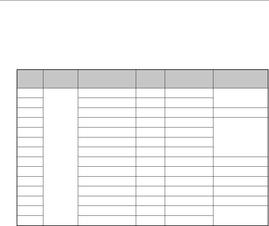
Wireless IEEE802.11 Channel Set
Frequency band 2400 to 2483.5 MHz *1
Channel ID
1 2412
2 2417
3 2422
4 2427
5 2432
6 2437
7 2442
8 2447
9 2452
10 2457 *1
11 2462
*1: The channel set at time of purchase
The wireless LAN channel settings is managed in the following way:
•When connected to the infrastructure with a wireless LAN, The station automatically switches
to the wireless LAN access point channel. When it is roaming between different access points,
the station automatically switches channels when necessary. The station switches channels
between 1 and 11. It is necessary to make this the range for the wireless LAN access-point set
channel.
•When connecting the wireless LAN with a “peer to peer” mode, channel 10 is used.
98
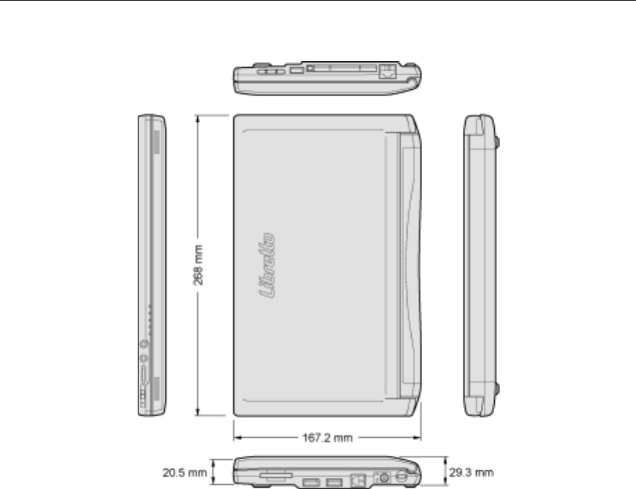
Exterior Dimension Diagram
* These measurements do not include protrusions.
99
Supported Video Mode
The regulations that determine the maximum possible number of colors and screen resolution
that is controlled by the display controller is called the video mode.
All the video modes that this product supports in English mode are shown below.
Usually the mode number is used by the programmer to differentiate between the various modes.
When application software specifies a mode based on the mode number, that number may not
match the number in the diagram. In this case, select the original resolution, font size and
number of colors.
Video
Mode Format Resolution Font
Size Number of
colors CRT Refresh
Rate (Hz)
— 800 × 600 dots — 256/256K
—1024 × 768 dots *1 — 256/256K 60/75/85/100
— 1280 × 600 dots *1 — 256/256K 60
—1280 × 1024 dots *1 — 256/256K
—1600 × 1200 dots *1 — 256/256K
— 800 × 600 dots — 64K/64K
—1024 × 768 dots *1 — 64K/64K
60/75/85/100
— 1280 × 600 dots — 64K/64K 60
—1280 × 1024 dots *1 — 64K/64K 60/75/85/100
— 1600 × 1200 dots *1 — 64K/64K 60
—800 × 600 dots — 16M/16M 60/75/85/100
— 1024 × 768 dots *1 — 16M/16M 60/75/85
—1280 × 600 dots *2 — 16M/16M
—
SVGA
Graphics
1280 × 1024 dots *2 — 16M/16M 60
*1: When the display is LCD, a semblance of the screen is displayed within the actual screen
(1280 × 600).
(Caution) Some of the screen modes have different refresh rate modes that can not be used
in multimonitor.
*2: When the display is a CRT, s semblance of the screen is displayed within the actual screen
(1280 × 600).

100
Hardware Resources
You can confirm the memory map, I/O port map and resources that use IRQ and DMA in the
following way.
There are modifications depending upon the environment (hardware/software) that is being used.
1. Click [Start], [All programs], [Accessories], [System tools] and [System information].
2. Double click on [Hardware resource] in the tree on the left side of the screen.
3. Click the items that you want to confirm.
Memory map: [Memory]
I/O port map: [I/O]
Resources that use IRQ: [IRQ]
Resources that use DMA: [DMA]
101
2. INTERFACE SPECIFICATIONS
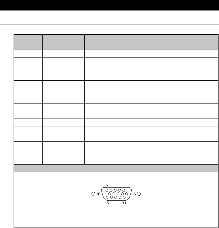
RGB Interface (Mini RGB Cable)
Pin
Number Signal name Explanation Signal
Direction
1 CRV Red video signal O
2 CGV Green video signal O
3 CBV Blue video signal O
4 Reserved Reserve
5 GND Signal ground
6 GND Signal ground
7 GND Signal ground
8 GND Signal ground
9 Reserved Reserve
10 GND Signal ground
11 Reserved Reserve
12 SDA SDA transmission signal I/O
13 -CHSYNC Horizontal synchronization signal O
14 -CVSYNC Vertical synchronization signal O
15 SCL SCL data clock signal I/O
Connector diagram
High density D-SUB 3-row 15-pin male plug
Signal name: A minus (–) is attached to signals that are negative logic values.
Signal direction (I): Input to the personal computer.
Signal direction (O): Output from the personal computer.
102
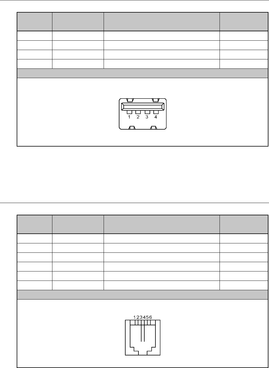
USB Interface
Pin
Number Signal name Explanation Signal
Direction
1VCC+5V
2 –Data Minus data I/O
3 +Data Plus data I/O
4 GND Signal ground
Connector diagram
Signal name: A minus (–) is attached to signals that are negative logic values.
Signal direction (I): Input to the personal computer.
Signal direction (O): Output from the personal computer.
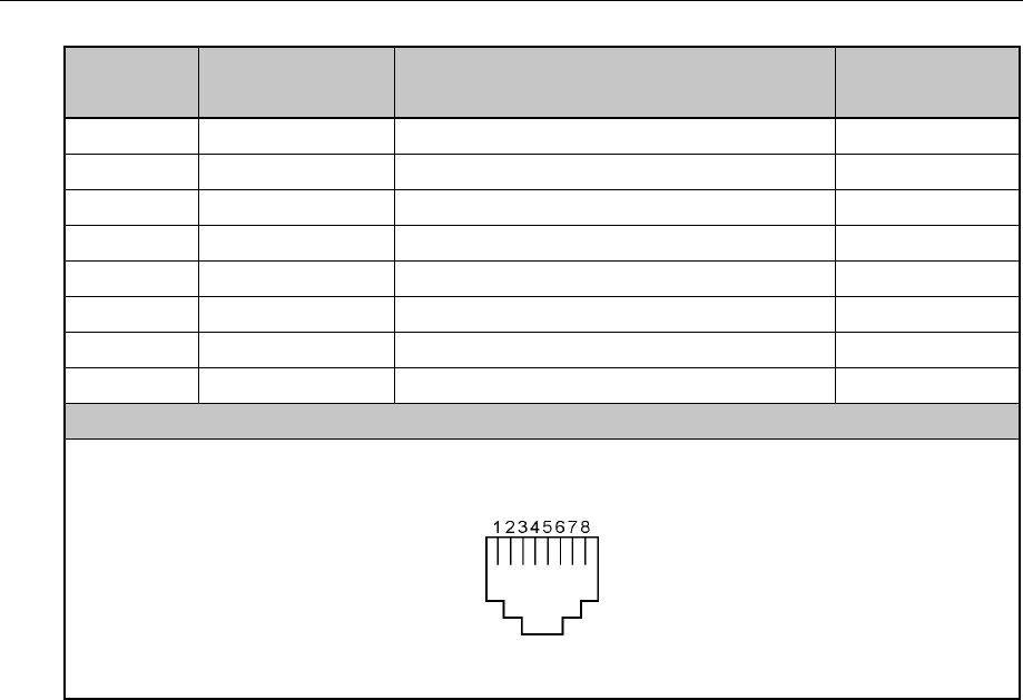
Modem Interface
Pin
Number Signal name Explanation Signal
Direction
1 — No contact
2 — No contact
3 TIP Telephone circuit I/O
4 RING Telephone circuit I/O
5 — No contact
6 — No contact
Connector diagram
Signal direction (I): Input to the personal computer.
Signal direction (O): Output from the personal computer.
103
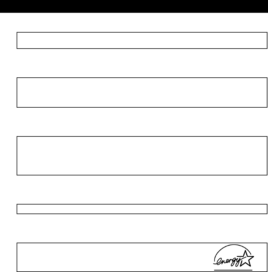
LAN Interface
Pin
Number Signal name Explanation Signal
Direction
1 TX Transmission data (+) O
2 –TX Transmission data (–) O
3 RX Reception data (+) I
4 Unused Not in use
5 Unused Not in use
6 –RX Reception data (–) I
7 Unused Not in use
8 Unused Not in use
Connector diagram
Signal name: A minus (–) is attached to signals that are negative logic values.
Signal direction (I): Input to the personal computer.
Signal direction (O): Output from the personal computer.
104
3. TECHNICAL STANDARD COMPLIANCE
Self Regulation of Leakage Current
This equipment complies with the international standard for personal computers (PC-11-1988)
determined by the Japan Electronics and Information Technology Industries Association.
Instantaneous Drop in Voltage
This equipment satisfies the guidelines for personal computer instantaneous drop in voltage
countermeasures determined by the Japan Electronics and Information Technology Industries
Association. However, instantaneous drops in voltage that exceed the guidelines may cause
some trouble.
Self Regulation of Electronic Interference
This equipment is a class B information Technology device based on the Voluntary Control
Council for Interference by Information Technology (VCCI) standard. This equipment is aimed
at use in a home environment, but this equipment may cause reception interference if used in
proximity to radios or televisions.
Refer to the manual for correct operating procedure.
Harmonic Guidelines
This equipment is a “Harmonic Guideline Compliant Product”.
International Energy Star Program
As a corporate member of the international energy star program,
this product has been determined to satisfy the standards related to
the international energy star program products.
REFERENCE: See “Chapter 4.2 Power saving” for information about energy saving settings.
105
FCC Information
Product name : Libretto L5/080TN
Model number : PAL5080TN
FCC Notice “Declaration of Conformity Information”
This equipment has been tested and found to comply with the limits for a Class B digital device,
pursuant to Part 15 of the FCC rules. These limits are designed to provide reasonable protection
against harmful interference in a residential installation. This equipment generates, uses and can
radiate radio frequency energy and, if not installed and used in accordance with the instructions,
it may cause harmful interference to radio communications. However, there is no guarantee that
interference will not occur in a particular installation. If this equipment does cause harmful
interference to radio or television reception, which can be determined by turning the equipment
off and on, the user is encouraged to try to correct the interference by one or more of the
following measures:
" Reorient or relocate the receiving antenna.
" Increase the separation between the equipment and receiver.
" Connect the equipment into an outlet on a circuit different from that to which the receiver is
connected.
" Consult the dealer or an experienced radio/TV technician for help.
WARNING: Only peripherals complying with the FCC rules class B limits may be attached to
this equipment. Operation with non-compliant peripherals or peripherals not
recommended by TOSHIBA is likely to result in interference to radio and TV
reception. Shielded cables must be used between the external devices and the
computer’s or external monitor port, USB port, and microphone jack. Changes or
modifications made to this equipment, not expressly approved by TOSHIBA or
parties authorized by TOSHIBA could void the user’s authority to operate the
equipment. The modular cable that comes with the computer must be used to
connect a modem.
FCC Conditions
This device complies with Part 15 of the FCC Rules. Operation is subject to the following two
conditions:
1. This device may not cause harmful interference.
2. This device must accept any interference received, including interference that may cause
undesired operation.
For Wireless LAN:
The radiated output power of the Toshiba Wireless LAN Mini PCI Card is far below the FCC radio
frequency exposure limits. Nevertheless, the Toshiba Wireless LAN Mini PCI Card shall be used in
such
A manner that the potential for human contact during normal operation is minimized. The antenna(s)
Used in this device are located at the upper edge of the LCD screen, a minimum separation distance of

106
5.0 cm must be maintained between the user and the antenna(s) to ensure exposure compliance.
Contact
Address : TOSHIBA America Information Systems, Inc.
9740 Irvine Boulevard
Irvine, California 92618-1697
Telephone : (949) 583-3000
EU Declaration of Conformity
TOSHIBA declares, that the product: PAL5080TN** conforms to the following
Standards:
Supplementary Information: “The product complies with the requirements of the Low Voltage
Directive 73/23/EEC and the EMC Directive 89/336/EEC and the
R & TTE Directive 1999/05/EEC.”
This product is carrying the CE-Mark in accordance with the related European Directives.
Responsible for CE-Marking is TOSHIBA Europe, Hammfelddamm 8, 41460 Neuss, Germany.

107
Cautions When Using the Modem
When using the internal modem in this product, take the following precautions.
The internal modem complies with the Japan Approvals Institute
for Telecommunications Equipment regulation 50 item 1 for
technical standard compliance.
Compliance number
A00-0940JP
• Regions where the modem can be used
The internal modem in your computer can be used in the following countries and regions:
Iceland, Ireland, U.S.A, U.A.E, U.K., Israel, Italia, India, Indonesia, Egypt, Estonia, Australia,
Austria, Oman, Netherlands, Canada, Korea, Greece, Kuwait, Saudi Arabia, Singapore,
Switzerland, Sweden, Spain, Sri Lanka, Slovakia, Slovenia, Thailand, Taiwan, Czech, China,
Denmark, Germany, Turkey, Japan, New Zealand, Norway, Pakistan, Hungary, Bangladesh,
Philippines, Finland, France, Bulgaria, Belgium, Poland, Portugal, Hong Kong, Malta,
Malaysia, South Africa, Morocco, Latvia, Lithuania, Luxemburg, Lebanon, Russia
As of April 2002
Because license has not been granted for operation in some other countries, be careful to not use
it in those other countries.
In countries where the modem can not be used, purchase a modem that can be used in those
countries.
If the line connecting the internal modem is PBX or some other, it is possible that it may not
function.
It is understood that, TOSHIBA bears no responsibility for any danger or damage resulting from
failure to adhere to the above precautions.
• Limits on automatic re-transmission
If the internal modem exceeds two redials, “BLACK LISTED” is returned without transmitting
(If the “BLACK LISTED” response code becomes a problem, set the redial to less than two
times or set the time between redials to greater than one minute).
The internal modem’s automatic redial function is in accordance with the technical standard of
the Electronic Communications law (Analog Telephone Terminals) “Automatic redial function
is within two times (However, within three minutes of the first transmission)”.
NOTES:•When thunderclouds are approaching, unplug the modular plug from the telephone
modular jack. If lightning strikes the telephone line, the modem or your computer
may be damaged.
•When using the internal modem, it is necessary to set it so that is complies with the
region in which it is being used.
108
Conformity Statement
The equipment has been approved to [Commission Decision “CTR21”] for pan-European single
terminal connection to the Public Switched Telephone Network (PSTN).
However, due to differences between the individual PSTNs provided in different
countries/regions the approval does not, of itself, give an unconditional assurance of successful
operation on every PSTN network termination point.
In the event of problems, you should contact your equipment supplier in the first instance.
Network Compatibility Statement
This product is designed to work with, and is compatible with the following networks. It has
been tested to and found to confirm with the additional requirements conditional in EG 201 121.
Germany - ATAAB AN005,AN006,AN007,AN009,AN010 and
DE03,04,05,08,09,12,14,17
Greece - ATAAB AN005,AN006 and GR01,02,03,04
Portugal - ATAAB AN001,005,006,007,011 and P03,04,08,10
Spain - ATAAB AN005,007,012, and ES01
Switzerland - ATAAB AN002
All other countries/regions - ATAAB AN003,004
Specific switch settings or software setup are required for each network, please refer to the
relevant sections of the user guide for more details.
The hookflash (timed break register recall) function is subject to separate national type
approvals. If has not been tested for conformity to national type regulations, and no guarantee of
successful operation of that specific function on specific national networks can be given.
109
Pursuant to FCC CFR 47, Part 68:
When you are ready to install or use the modem, call your local telephone company and give
them the following information:
- The telephone number of the line to which you will connect the modem
- The registration number that is located on the device
The FCC registration number of the modem will be found on either the device which is to be
installed, or, if already installed, on the bottom of the computer outside of the main system label.
- The Ringer Equivalence Number (REN) of the modem, which can vary.
For the REN of your modem, refer to your modem's label.
The modem connects to the telephone line by means of a standard jack called the USOC RJ11C.
Type of Service
Your modem is designed to be used on standard-device telephone lines.
Connection to telephone company-provided coin service (central office implemented systems) is
prohibited. Connection to party lines service is subject to state tariffs. If you have any questions
about your telephone line, such as how many pieces of equipment you can connect to it, the
telephone company will provide this information upon request.
Telephone Company Procedures
The goal of the telephone company is to provide you with the best service it can.
In order to do this, it may occasionally be necessary for them to make changes in their
equipment, operations, or procedures. If these changes might affect your service or the operation
of your equipment, the telephone company will give you notice in writing to allow you to make
any changes necessary to maintain uninterrupted service.
If Problems Arise
If any of your telephone equipment is not operating properly, you should immediately remove it
from your telephone line, as it may cause harm to the telephone network. If the telephone
company notes a problem, they may temporarily discontinue service. When practical, they will
notify you in advance of this disconnection. If advance notice is not feasible, you will be notified
as soon as possible. When you are notified, you will be given the opportunity to correct the
problem and informed of your right to file a complaint with the FCC.
In the event repairs are ever needed on your modem, they should be performed by TOSHIBA
Corporation or an authorized representative of TOSHIBA Corporation.
110
Disconnection
If you should ever decide to permanently disconnect your modem from its present line, please
call the telephone company and let them know of this change.
Fax Branding
The Telephone Consumer Protection Act of 1991 makes it unlawful for any person to use a
computer or other electronic device to send any message via a telephone fax machine unless
such message clearly contains in a margin at the top or bottom of each transmitted page or on the
first page of the transmission, the date and time it is sent and an identification of the business,
other entity or individual sending the message and the telephone number of the sending machine
or such business, other entity or individual.
In order to program this information into your fax modem, you should complete the setup of
your fax software before sending messages.
111
Instructions for IC CS-03 Certified Equipment
1. NOTICE: The Industry Canada label identifies certified equipment. This certification means
that the equipment meets certain telecommunications network protective, operational and
safety requirements as prescribed in the appropriate Terminal Equipment Technical
Requirements document(s). The Department does not guarantee the equipment will operate
to the user's satisfaction.
Before installing this equipment, users should ensure that it is permissible to be connected to
the facilities of the local telecommunications company. The equipment must also be
installed using an acceptable method of connection.
The customer should be aware that compliance with the above conditions may not prevent
degradation of service in some situations.
Repairs to certified equipment should be coordinated by a representative designated by the
supplier. Any repairs or alterations made by the user to this equipment, or equipment
malfunctions, may give the telecommunications company cause to request the user to
disconnect the equipment.
Users should ensure for their own protection that the electrical ground connections of the
power utility, telephone lines and internal metallic water pipe system, if present, are
connected together. This precaution may be particularly important in rural areas.
Caution: Users should not attempt to make such connections themselves, but should contact
the appropriate electric inspection authority, or electrician, as appropriate.
2. The user manual of analog equipment must contain the equipment's Ringer Equivalence
Number (REN) and an explanation notice similar to the following:
The Ringer Equivalence Number (REN) of the modem, which can vary.
For the REN of your modem, refer to your modem's label.
NOTE: The Ringer Equivalence Number (REN) assigned to each terminal device provides
an indication of the maximum number of terminals allowed to be connected to a
telephone interface. The termination on an interface may consist of any
combination of devices subject only to the requirement that the sum of the Ringer
Equivalence Numbers of all the devices does not exceed 5.
3. The standard connecting arrangement (telephone jack type) for this equipment is jack
type(s): USOC RJ11C.
The IC registration number of the modem is shown below.
CANADA: 1353 11026A
112
Notes for Users in Australia and New Zealand
Modem Warning Notice for Australia
Modems connected to the Australian telecoms network must have a valid Austel permit. This
modem has been designed to specifically configure to ensure compliance with Austel standards
when the country/region selection is set to Australia.
The use of other country/region setting while the modem is attached to the Australian PSTN
would result in you modem being operated in a non-compliant manner.
To verify that the country/region is correctly set, enter the command ATI which displays the
currently active setting.
To set the country/region permanently to Australia, enter the following command sequence:
AT%TE = 1
ATS133 = 1
AT&F
AT&W
AT%TE = 0
ATZ
Failure to set the modem to the Australia region setting as shown above will result in the modem
being operated in a non-compliant manner. Consequently, there would be no permit in force for
this equipment and the Telecoms Act 1991 prescribes a penalty of $12,000 for the connection of
non-permitted equipment.
Notes for Use of this Device in New Zealand
- The grant of a Telepermit for a device in no way indicates Telecom acceptance of
responsibility for the correct operation of that device under all operating conditions. In
particular the higher speeds at which this modem is capable of operating depend on a specific
network implementation which is only one of many ways of delivering high quality voice
telephony to customers. Failure to operate should not be reported as a fault to Telecom
- In addition to satisfactory line conditions a modem can only work properly if:
a/ it is compatible with the modem at the other end of the call and
b/ the application using the modem is compatible with the application at the other end
of the call - e.g., accessing the Internet requires suitable software in addition to a
modem.
- This equipment shall not be used in any manner which could constitute a nuisance to other
Telecom customers.
113
- Some parameters required for compliance with Telecom’s PTC
Specifications are dependent on the equipment (PC) associated with this modem. The
associated equipment shall be set to operate within the following limits for compliance with
Telecom Specifications:
a/ There shall be no more than 10 call attempts to the same number within any 30
minute period for any single manual call initiation, and
b/ The equipment shall go on-hook for a period of not less than 30 seconds between the
end of one attempt and the beginning of the next.
c/ Automatic calls to different numbers shall be not less than 5 seconds apart.
- Immediately disconnect this equipment should it become physically damaged, and arrange for
its disposal or repair.
- The correct settings for use with this modem in New Zealand are as follows:
ATB0 (CCITT operation)
AT&G2 (1800 Hz guard tone)
AT&P1 (Decadic dialing make-break ratio =33%/67%)
ATS0 = 0 (not auto answer)
ATS6 = 4 (Blind dial delay)
ATS7 = less than 90 (Time to wait to carrier after dialing)
ATS10 = less than 150 (loss of carrier to hangup delay, factory default of 15 recommended)
ATS11 = 90 (DTMF dialing on/off duration = 90 ms)
ATX2 (Dial tone detect, but not (U.S.A.) call progress detect)
- When used in the Auto Answer mode, the S0 register must be set with a value 3 or 4. This
ensures:
(a) A person calling your modem will hear a short burst of ringing before the modem answers.
This confirms that the call has been successfully switched through the network.
(b) Caller identification information (which occurs between the first and second ring cadences)
is not destroyed.
- The preferred method of dialing is to use DTMF tones (ATDT...) as this is faster and more
reliable than pulse (decadic) dialing. If for some reason you must use decadic dialing, your
communications program must be set up to record numbers using the following translation
table as this modem does not implement the New Zealand “Reverse Dialing” standard.
Number to be dialed: 0 1 2 3 4 5 6 7 8 9
Number to program into computer: 0 9 8 7 6 5 4 3 2 1
Note that where DTMF dialing is used, the numbers should be entered normally.
114
- The transmit level from this device is set at a fixed level and because of this there may be
circumstances where the performance is less than optimal.
Before reporting such occurrences as faults, please check the line with a standard
Telepermitted telephone, and only report a fault if the phone performance is impaired.
- It is recommended that this equipment be disconnected from the Telecom line during electrical
storms.
- When relocating the equipment, always disconnect the Telecom line connection before the
power connection, and reconnect the power first.
- This equipment may not be compatible with Telecom Distinctive Alert cadences and services
such as FaxAbility.
Note That Fault Callouts Caused By Any Of The Above Causes May Incur
A Charge From Telecom
General Conditions
As required by PTC 100, please ensure that this office is advised of any changes to the
specifications of these products which might affect compliance with the relevant PTC
Specifications.
The grant of this Telepermit is specific to the above products with the marketing description as
stated on the Telepermit label artwork. The Telepermit may not be assigned to other parties or
other products without Telecom approval.
A Telepermit artwork for each device is included from which you may prepare any number of
Telepermit labels subject to the general instructions on format, size and colour on the attached
sheet.
The Telepermit label must be displayed on the product at all times as proof to purchasers and
service personnel that the product is able to be legitimately connected to the Telecom network.
The Telepermit label may also be shown on the packaging of the product and in the sales
literature, as required in PTC 100.
The charge for a Telepermit assessment is $337.50. An additional charge of $337.50 is payable
where an assessment is based on reports against non-Telecom New Zealand Specifications.
$112.50 is charged for each variation when submitted at the same time as the original.
An invoice for $NZ1237.50 will be sent under separate cover.

115
TROUBLE CHECKLIST
Contact Toshiba PC Dial for information about operating your personal computer.
TOSHIBA PC DIAL
Technical questions can be answered on the telephone.
* Hours: 9:00 to 19:00 (except for holidays and from December 31 to January 3)
Navi-Dial
National Common Telephone Number 0570-00-3100
[Be careful to dial the correct telephone number to avoid making mistakes.]
Customer inquiries are automatically connected to the nearest of six locations throughout the
country (Chiba, Osaka, Nagoya, Fukuoka, Sendai and Sapporo).
In Navi-Dial, an announcement about calling costs is made after dialing. This is the regular rate
for telephone calls to the location nearest to the customer; it is not a fee for technical support
(there is no technical support fee).
You should understand that Navi-Dial automatically uses NTT lines, even if you have contracted
with a different carrier or My-Line-Plus.
The following calls will not connect with the above telephone system. Customers that fall into
this category should use 043-298-8780 (direct line).
•Calls from overseas
•Mobile phones and PHS
•Connections made through telephone companies other than NTT such as 0088 or 0077.
•General use contract lines for industry
•Telephones that have been set to not use the “0570” by industry PBX
TIPS:•Telephones that use the α-LCR/Super-LCR among others, can use “0570-00-3100”
by disabling the settings, see the “manual attached to the telephone” for the
disabling procedure.
•You can also receive product information, Q & A and other information by Fax (G3
standard) from “Toshiba PC FAX Information Service”.
•One on one consultation is available (technical consultation and labor are fee-based)
at “Toshiba PC Techno-Center” (in Tokyo and Osaka).
REFERENCE: For details see the “Guide to Toshiba PC Support”.
116
Trouble Checklist
For smoother response, check the following details before contacting Toshiba.
If Toshiba PC Dial asks you for information other than the following, such as the operating
system version and the type of CPU, check this information by clicking the [Basic Information
Display] button in [PC Diagnostic Tool].
[Regarding the environment you are using
(the personal computer environment that you are currently using).]
Q . 1 What is the name (model name) of the personal computer that you are using?
(See the computer itself or the operator’s manual)
Name of device:
Enquiry will be made about the following information.
(Production number: , Placeof Purchase: , Date of Purchase: , etc.)
Q . 2 What software environment are you using?
Explain what system and application you are using, such as Windows XP Home.
OS (System name):
Others:
Q . 3 What symptoms have occurred?
Symptoms:
Q . 4 After what operations did these symptoms occur?
Details of operations:
Q . 5 Did error messages or other things appear?
Details of displays:
117
Q . 6 How frequently do the symptoms occur?
#They occurred only once and did not occur again.
#They occur until the power is cut, but do not occur when restarting after cutting the power.
#They always occur when restarting after cutting the power.
#Others:
Q . 7 Do the symptoms occur after a particular operation?
#They occur after a specific operation.
#They occur after any operation.
#Others:
Q . 8 For consultation about the Internet and transmissions.
Name of your provider:
Name of the modem you are using:
Type of line you are using:
#Transmission from an extension phone #My line contract
#ISDN #Mobile phone #DSL/Cable television
Q . 9 If the inquiry is about a peripheral device, what is the name of the peripheral device?
Name of the device: (Product name)
Name of the manufacturer: