Toshiba Client Solutions PL5080WL Libretto User Manual Manual 3of7
Toshiba Corporation Libretto Manual 3of7
Contents
Manual 3of7
8
1. FEATURES
This section briefly describes the features of your computer.
For more information on individual features, see their respective sections.
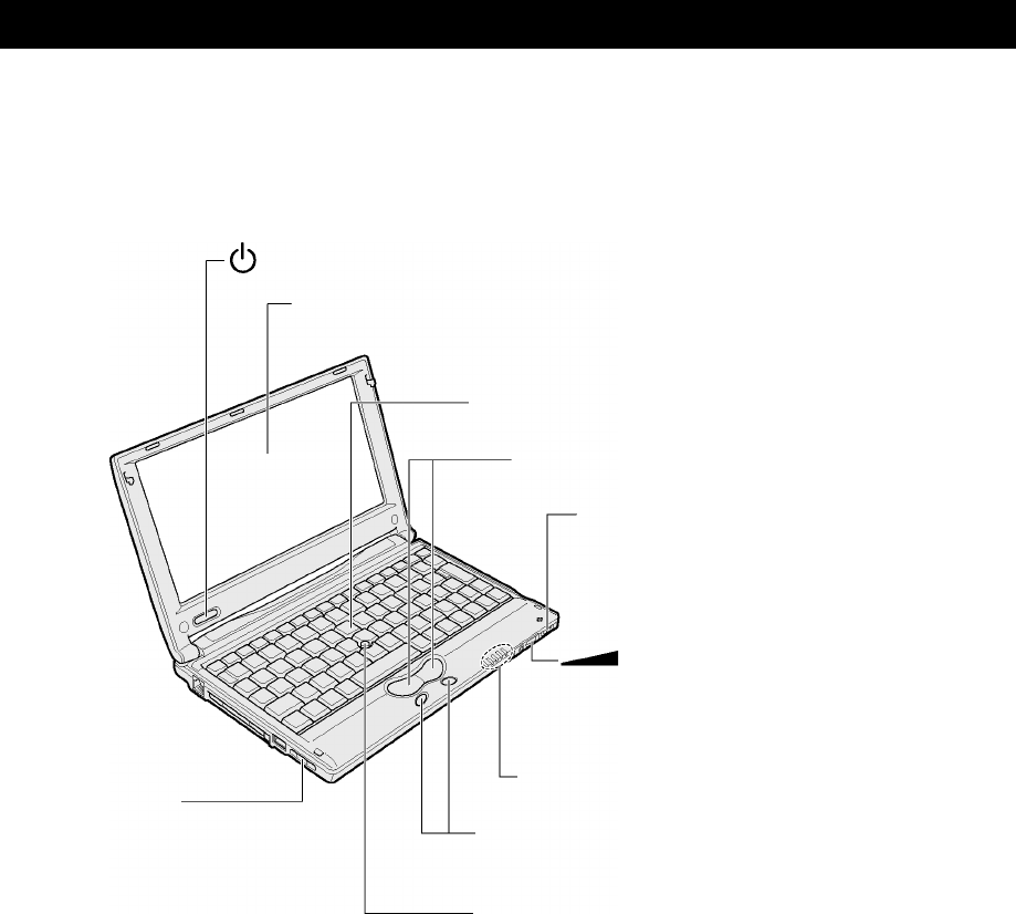
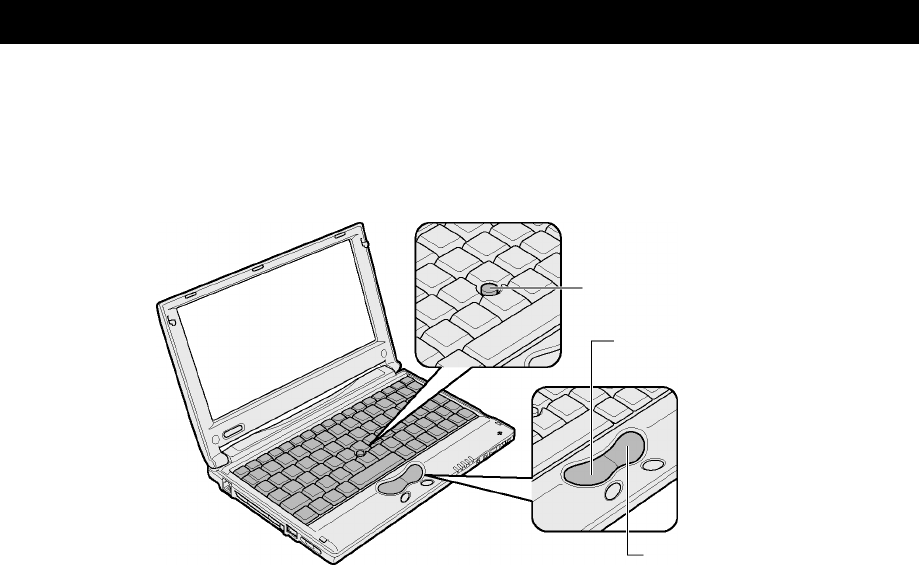
! Front View
Power switch
Display
1280 × 600 pixel color TFT LCD
Keyboard (" P.XX)
Control buttons (" P.XX)
Wireless communication switch
* For models with the wireless LAN
feature only
Volume dial
Turn the dial to the right to increase and to the
left to decrease the volume.
System indicator
Scroll buttons
Use the buttons to scroll the screen.
Accupoint II (" P.XX)
Air vent
Heat generated inside your
computer is vented through
this opening.
9
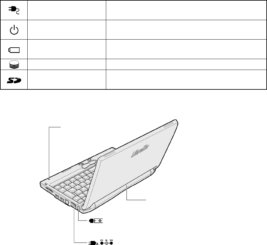
System Indicator
DC IN LED Connect the power cord.
See “1 Turning on the power” in Chapter 2.
Power LED Indicates the power state.
See “1 Turning on the power” in Chapter 2.
Battery LED Indicates the standard battery state.
See “1 Use of the battery pack” in Chapter 4.
Disk LED Indicates that the standard hard disk is being accessed.
SD Card LED Indicates that the SD memory card is being accessed.
See “8 SD cards” in this chapter.
! Rear View
Internal microphone
(" P.XX)
Battery pack (" P.XX)
Security lock slot
Connect a chain or something to secure your computer.
Power connector
Connect the supplied AC adapter.
NOTE:•For security lock devices, ask your dealer about compatibility.
10
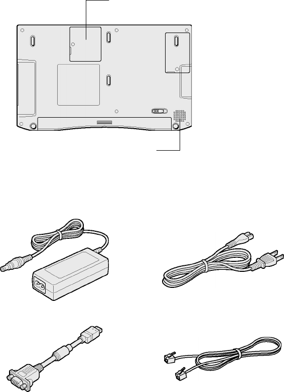
! Rear View
Additional memory slot (" P.XX)
Speaker (" P.XX)
! Supplied Accessories
AC adapter
Mini-RGB cable
Power cord
Modular cable
11
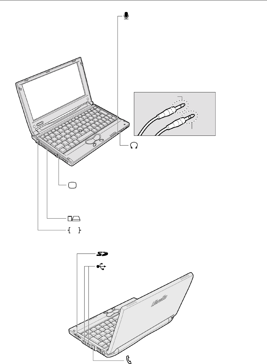
Optional Device Connections
Microphone IN terminal
Bi-polar mini-jack
Mini-RGB connector (" P.XX)
Connect one end of the supplied mini-RGB cable here
and the other end to a CRT display.
Connect a microphone here.
∙You can use a monaural microphone only.
∙You can use a tri-polar mini-jack plug with a
3.5-mm diameter.
You can also use a bi-polar mini-jack plug
with a 3.5-mm diameter if the microphone is
provided with a battery and requires no
power supply.
Tri-polar mini-jack
Headphone OUT terminal
Connect a headphone here.
Sound is output in stereo.
Plug a stereo mini-jack with a 3.5-mm diameter.
PC card slot (" P.XX)
LAN connector (" P.XX)
CB
Enter
SD memory card slot (" P.XX)
Modular jack (" P.XX)
To use the modem feature, connect your computer to a
telephone outlet with the supplied modular cable.
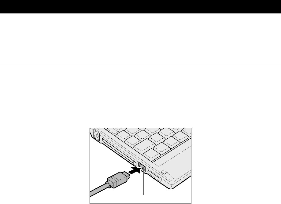
USB connector
Connect a USB-compliant
device.
12
2. ACCUPOINT II
When you turn on your computer and start Windows, <pointer> appears on the screen. This is
called the pointer
Your computer is equipped with the Accupoint II and the control buttons (right and left) are used
to move the pointer.
Accupoint II
Left control button
Right control button
NOTE:•The on-screen pointer may move without control with the Accupoint II in the
following cases:
- when you have just turned on your computer
- when you have just taken your finger off the Accupoint II after you moved the
pointer with force in one direction
- when the temperature has drastically changed
In the above cases, leave your computer for at least 10 seconds before using the
Accupoint II.
13
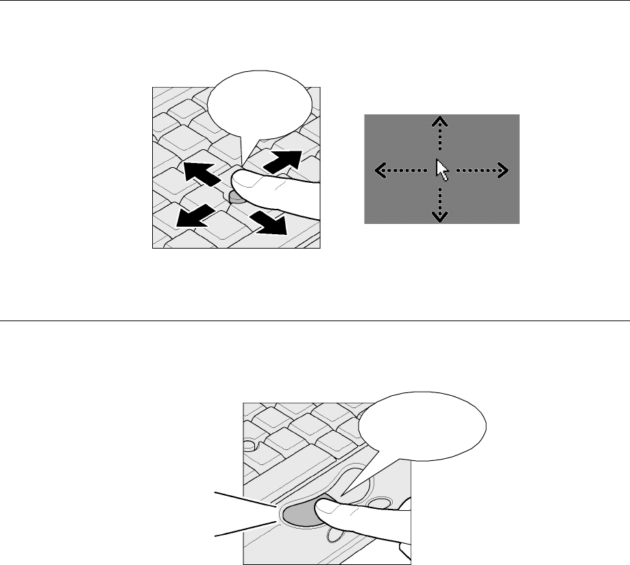
Moving the Pointer
Place your finger on the Accupoint II, press and move it vertically or horizontally. The pointer
moves in accordance with your finger movement.
Move your
finger.
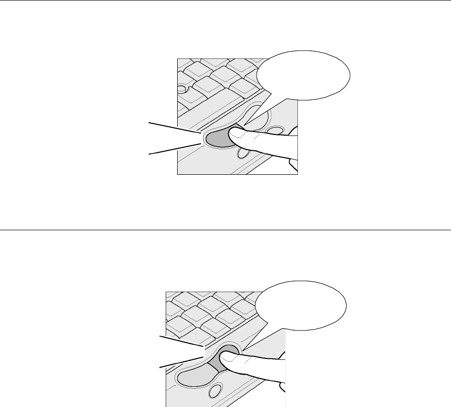
Click
Place the pointer onto a desired position and press the left button once.
Click the button to select an icon or letter, etc.
Press the left
button once.
Click
14
Double-click
Place the pointer onto a desired position and press the left button quickly twice.
Double-click the button to open a file or to start an application.
Press the left
button twice.
Click, click
Right-click
Place the pointer onto a desired position and press the right button once.
A menu appears for selection.
Press the left
button once.
Click
15
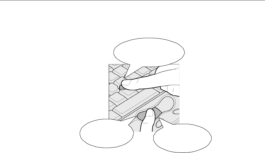
Drag-and-drop
Place the pointer onto a desired position, press and hold the left button (1), and then move the
pointer with the Accupoint II (2) (dragging). When the pointer reaches the destination point, take
your finger off the left button (3) (dropping).
(2) Push in the desired
direction.
(3) Take your finger
off.
(1) Keep pressing.
16
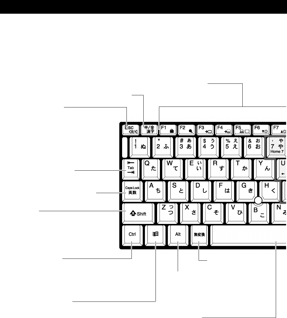
3. KEYBOARD
1. Functions of the Keys
This section briefly describes use of the keyboard and the function and name of the keys.
Half/full <KANJI> key
Esc (Escape) key
Use this key to cancel the operation.
Function keys
Use these keys to perform
the assigned operations.
Caps Lock Alphanumeric key
Tab key
Shift key
Use this key to temporarily switch
the upper and lower cases or to input
symbols.
Ctrl (Control) key
Use this key in combination with
another key to perform a specific
operation.
Win (Windows) key
Use this key to display the Windows Start menu
or, in combination with another key, to perform
a keyboard shortcut.
Alt (Alternate) key
Use this key in combination with
another key to perform a specific
operation.
Non-conversion key
Space key
Use this key to input a blank or to
convert characters to kanji characters.
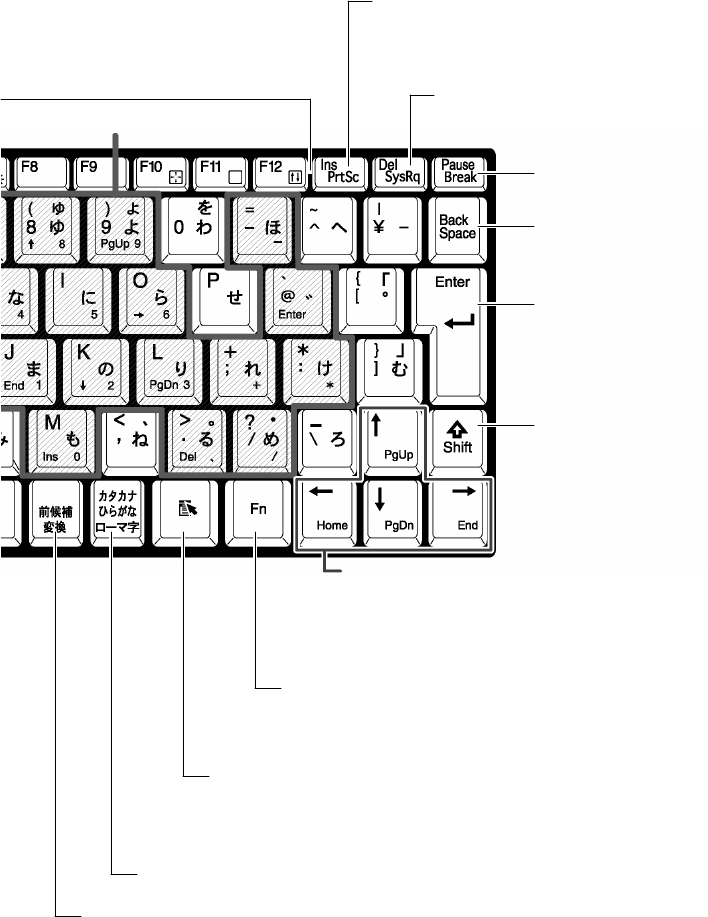
17
Pause <Break> key
Del (Delete) <SysRq (System Request)> key
Use this key to delete a character.
Ins (Insert) <PrtSC (Print Screen)> key
Use this key to switch the input mode: Insert and
Overwrite modes.
Fn key
Use this key to use the overlay keys or, in combination with the
function keys or the arrow keys to perform special functions.
Shift key
KATAKANA/HIRAGANA <ROMAJI> key
Arrow keys
Use these keys to move the cursor.
In combination with the Fn key, you can also use this key
to perform a special function.
Backspace key
Enter key
Use this key to execute an operation.
Overlay keys
Application key
Use this key to perform the same operations as the right control
button or the right mouse button.
Conversion key
18
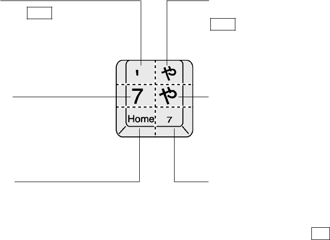
! Character keys
Use the character keys to input characters or symbols.
You can select one out of the two to six characters and symbols printed on a character key with
the control keys.
# Top left
Press and hold the Shift key and press
this key to input a symbol or an upper-
case letter of the alphabet.
# Top right
In Kana mode, press and hold the
Shift key and press this key to input
a symbol or the assimilated or
contracted sound of a hiragana
character.
# Middle left
Press this key only to input a number
or a lower-case letter of the alphabet.
In Caps Lock mode, you can press
this key to input an upper-case letter
of the alphabet.
# Middle right
In Kana mode, press this key to input
a hiragana character or a symbol.
# Bottom left
In Arrow mode, press this key to
control the cursor.
# Bottom right
In Num Lock mode, press this key to
enter a number.
REFERENCE: Arrow mode and Num Lock mode: See “Special functions with the Fn key” in
this chapter.
19
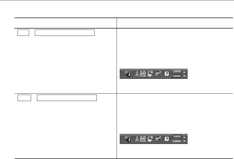
Input Control Keys
The control keys for character input are listed below:
Key Description
Ctrl + Caps Lock Alphanumeric 1Activates the one-byte KATAKANA input mode.
In this mode, you can input the HIRAGANA
character printed at the bottom right on the key
top in the one-byte KATAKANA character.
When the IME toolbar is on the desktop, [KANA]
changes in color.
Alternatively, you can click on [KANA] to activate
the one-byte KATAKANA input mode.
Shift + Caps Lock Alphanumeric 1Activates the upper-case lock mode. In this
mode, you can input the alphanumeric character
printed at the top left on the key top in the upper
case.
When the IME toolbar is on the desktop, [CAPS]
changes in color.
Alternatively, you can also click on [CAPS] to
activate the upper-case lock mode.
To deactivate the one-byte KATAKANA input mode or the upper-case lock mode, repeat the
key operation.
The priority in the locked state goes to the one-byte KATAKANA input mode, then to the upper-
case lock mode.
20
Special Function Keys with the Fn Key
Key Description
Fn + Esc 1<
<speaker mute>
Mutes the volume of the internal speaker or the
headphones. To resume the sound, press the
Fn + Esc keys again.
Fn + F1 1
<Instant security function>
Displays the lock icon at the top right of the
screen and turns off the screen display.
Protection with the password (by checking
[Protect with the password] or [Return to the
Welcome to Windows window at restart] on the
[Screen Saver] tab of the [Display Properties]
window) will enhance the security. To deactivate
the instant security function, do one of the
following:
(1) Press the Shift or Ctrl key or move the
Accupoint II.
(2) If multiple users are registered, click a user
name.
(3) Enter the Windows log-on password on the
password input window and press the
Enter key.
If protection with the password is not activated,
you can press the Shift or Ctrl key or move
the Accupoint II to deactivate the instant security
function.
Fn + F2 1
<Power saving mode setup>
Press the Fn + F2 keys to display the power
saving mode set with the Toshiba Power Saving
Utility.
To switch through the power saving modes,
press and hold the Fn key and press the F2 1
key.
Fn + F3 1
<Standby>
Press the Fn + F3 keys to display a dialog
window and click the [Yes] button to place your
computer on Standby. (*1)
Fn + F4 1
<Hibernate>
Press the Fn + F4 keys to display a dialog
window and click the [Yes] button to place your
computer in Hibernate. (*1)
Fn + F5 1
<Display device selection>
You can select a display device.
REFERENCE: For more information,
see “9 External display” in this
Chapter.
21
Key Description
Fn + F6 1
<Decrease screen brightness>
Press and hold the Fn key and press the F6 key
to decrease screen brightness by one level.
The screen icon shows the state of brightness. (*2)
Fn + F7 1
<Increase screen brightness>
Press and hold the Fn key and press the F7 key
to increase screen brightness by one level.
The screen icon shows the state of brightness. (*2)
Fn + F10 1
<Overlay function: arrow mode>
You can use the overlay keys as the cursor control
keys of which functions are printed at the bottom
left on the key top.
To deactivate the arrow mode, press the Fn +
F10 keys again.
Fn + F11 1
<Overlay function: number lock mode>
You can enter numbers that are printed at the
bottom right on the key top.
To deactivate the number lock mode, press the
Fn + F11 keys again.
Some applications, including Microsoft Excel, may
perform different functions.
Fn + F12 1
<Scroll lock mode>
In some applications, you can use the up, down,
left, and right arrow keys ↑ ↓ ← → for
scrolling the screen.
To deactivate the scroll lock mode, press the Fn 1
+ F12 keys again.
Fn + ↑ 1
<PgUp (Page Up)>
Press and hold the Fn key and press the up
arrow key ↑ to move to the previous page.
Fn + ↓ 1
<PgDn (Page Down)>
Press and hold the Fn key and press the down
arrow key ↓ to move to the next page.
Fn + ← 1
<Home>
Press and hold the Fn key and press the left
arrow key ← to move the cursor to the beginning
of the line or document.
Fn + → 1
<End>
Press and hold the Fn key and press the right
arrow key → to move the cursor to the end of the
line or document.
*1: If you check [Do not display this message again.] on the message window, the window
will not appear from then on.
*2: No change in brightness is allowed for 18 seconds immediately after the LCD is turned
on. The maximum brightness is applied in that period for stabilizing the LCD.
22
Shortcut keys with the Windows key
Combinations of the Windows key and another key for shortcuts are listed below:
Key Operation
+ R 1Displays the [Run] window.
+ M 1Minimizes all the windows to icons.
Shift + + M 1Maximizes all the window icons.
+ F1 1Starts “Help and Support Center”.
+ E 1Displays the [My Computer] window.
+ F 1Initiates the search for a file or folder.
Ctrl + + F 1Initiates the search for other computers.
+ Tab 1Moves the focus on the taskbar buttons.
+ Break 1Displays the [System Properties] window.
Special Function Keys
Special Function Key Operation
Start of the Task
Manager Ctrl + Alt + Del 1Displays the [Task Manager] window.
You can abort applications and the system.
Fn + PrtSc 1Copies the current desktop into the clipboard.Screen copy
Alt + Fn + PrtSc 1Copies the active window into the clipboard.
23
2. To Input Japanese
Your computer is provided with the Japanese input system MS-IME.
The Japanese input system is the software to input Japanese characters.
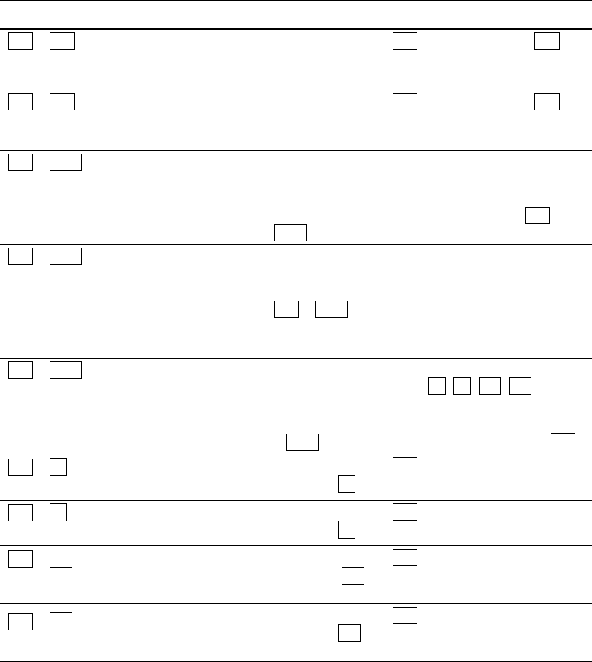
When you turn on your computer, you can input alphanumeric characters. To input Japanese
characters, press the Half/Full key.
When you activate the Japanese input mode, the IME toolbar appears as shown below:
Input Mode Selection
The default mode is the ROMAJI input mode.
To switch between the ROMAJI input mode and the KANA input mode, press the Alt +
KATAKANA/HIRAGANA keys.
When you restart your computer, the ROMAJI input mode is resumed.
To always use the same input mode, follow the steps below:
(1) Click the [Tool] icon ( ) on the toolbar.
(2) Click [Properties] on the menu that appears.
(3) On the [General] tab, select the input mode.
KANJI Character Conversion
To convert characters that you entered into KANJI characters, press the Space key.
If converted KANJI characters are not desired ones, press the Space key again to display
others.
If you press the Space key one more again, a list of KANJI characters appears.
Use the up ( ↑ ) or down ( ↓ ) arrow key to select desired ones and press the Enter key.
REFERENCE: For use of MS-IME, see “MS-IME Online Help”.
TIP:•To see the MS-IME online help, click the [Help] icon ( ) on the toolbar and click
[Microsoft(R) IME Standard 2002] → [Contents and Keyword].
24
4. VOLUME CONTROL
1. Controlling Speaker Volume
To adjust the speaker volume, use the volume dial or control it on Windows.
TIP:•Some applications may cause feedback between the external microphone and the
speaker. In such a case, do the following:
- Adjust the volume with the volume dial.
- Change the settings of the application in use.
- Move the external microphone away from the speaker.
Control with the Volume Dial
Turn the dial to the right to increase the volume or to the left to decrease the volume.
Muting
1. Press and hold the Fn key and press the Esc key.
Muting of the speaker is activated or deactivated.
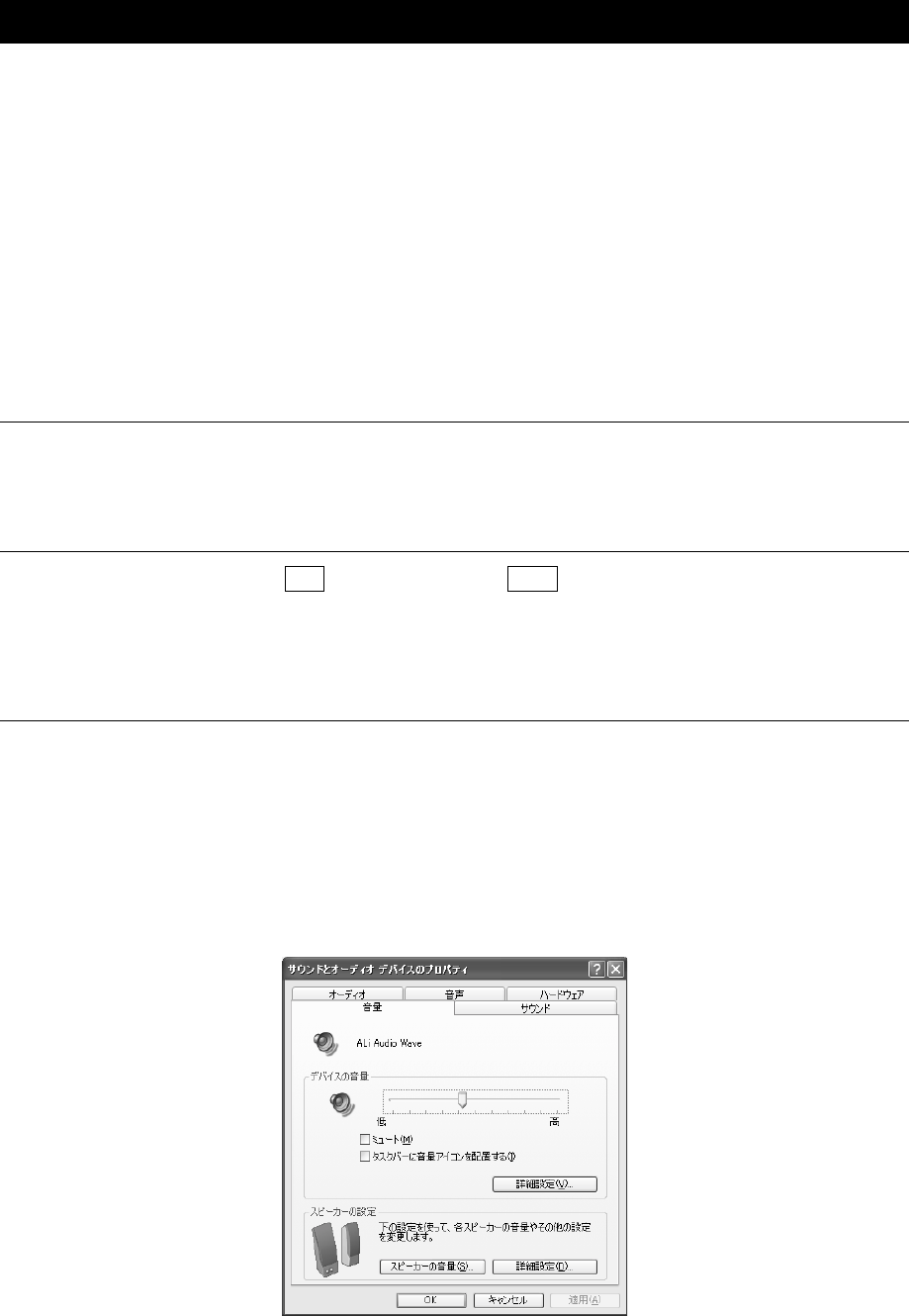
Control on Windows
! Sound and Audio Device Properties
(1) Click [Start] → [Control Panel].
(2) Click [Sounds, Speech, and Audio Devices].
(3) Click [Change the speaker settings].
The [Sound and Audio Device Properties] window appears.
(4) Drag the slider for [Device volume] on the [Volume] tab.
25
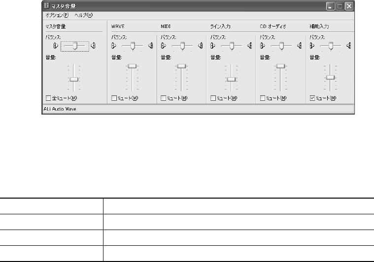
! Master Volume
To adjust the volume of individual files that you play back, follow the steps below:
(1) Click [Start] → [All Programs] → [Accessories] → [Entertainment] → [Volume Control].
(2) Drag the slider for each option vertically to adjust the volume.
Move the slider upward to increase the speaker volume. To mute the sound, click [Mute].
On the [Master Volume] window, you can adjust the following volume options.
Master Volume The overall volume
WAVE MP3 files, Wave files, music CD, DVD-Video
MIDI MIDI files
CD AUDIO Music CD (not for playback with Windows Media Player)
These options may vary depending on the application. For more information, see the manual that
comes with the application or “Master Volume Help”.
2. Controlling Audio and Voice Recording Volume
To adjust the recording level on your computer, follow the steps below:
1. Click [Start] → [All Programs] → [Accessories] → [Entertainment] → [Volume
Control].
2. Click [Options] → [Properties] on the menu bar.
3. Check [Recording] under [Volume control].
4. Confirm [Control to display].
Confirm that [Microphone] is checked.
5. Click the [OK] button.
26
6. On the [Recording Control] window, click [Select] for the device to use.
[Microphone]: when recording with the external microphone.
7. Move the slider for the selected device to adjust the volume.
TIPS:•You cannot select more than one device at the same time.
•If the music or speech that you want to record is applicable to [WAVE] on the
[Master Volume] window, the volume setting for [WAVE] also controls the
recording volume.

27
5. INTERNAL MODEM
The internal modem complies with ITU-T V.90. If the destination provider does not support
V.90, the connection speed will be up to 33.6 kbps.
! Notes on use
•When thunderclouds are approaching, unplug the modular plug from the telephone modular
jack. If lightning strikes the telephone line, the modem or your computer may be damaged.
•When the modular cable is connected to the modular jack on your computer, do not pull the
modular cable or relocate your computer, as it may damage the modular jack.
•Use of a commercially available branch adapter to connect the modem along with another
device may affect data communications with the modem or operations of the other device.
•If you want to use a line switcher, use the one that completely isolates the line from an unused
device.
TIP:•While the hard disk or CD-ROM of the PC card connection type is in operation, an
attempt to initiate communications may cause the following phenomena:
- Decrease in the communication speed
- Disconnection of the communication line
- Dialing failure
! AT Command
For the AT commands, see “Online Manual”.
! Modular cable connection
Be sure to read “Safety Information” before connecting a modular cable and using the internal
modem to observe the notes.
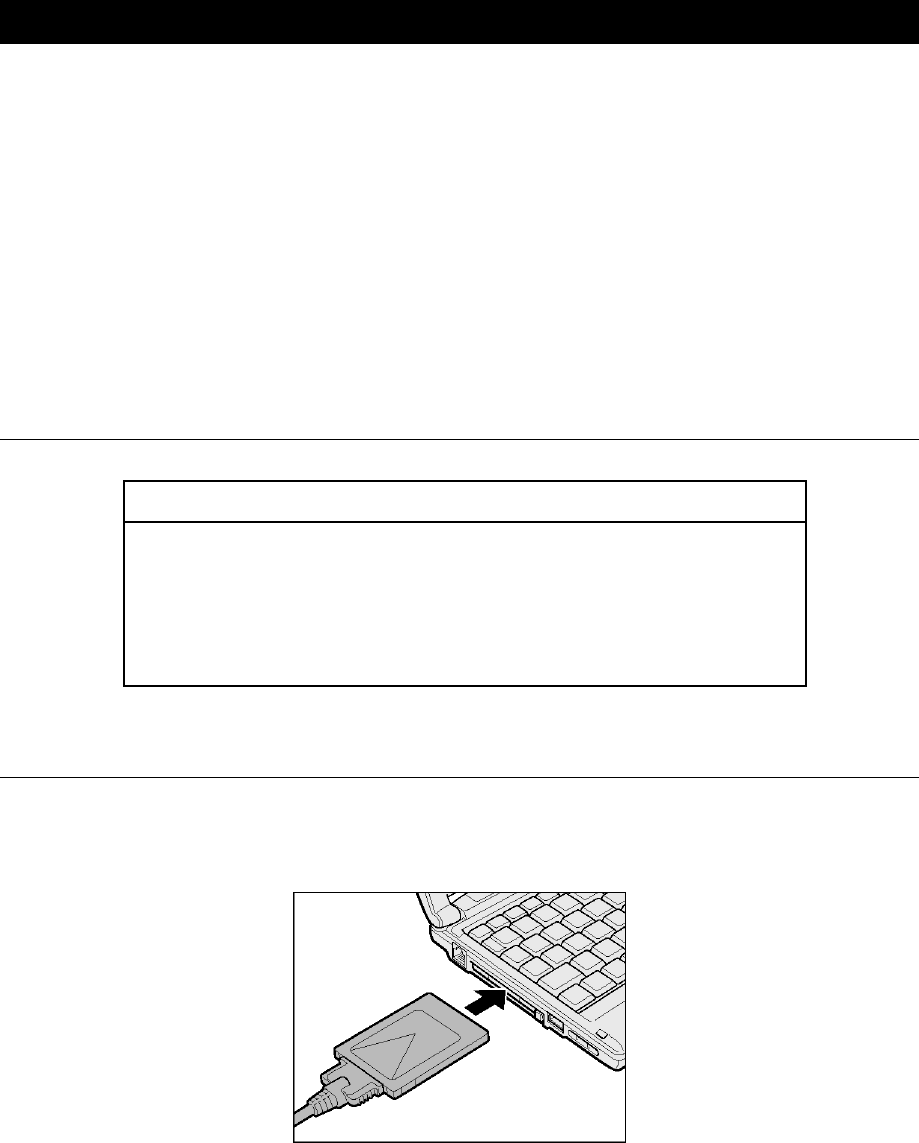
1. Insert the modular cable plug into the modular jack on your computer.
Be sure to insert the plug until it clicks.
2. Insert the other modular cable plug into a telephone outlet.
When using the ISDN line, insert the plug into the analog port on your terminal adapter
(TA) or dial-up router.
28
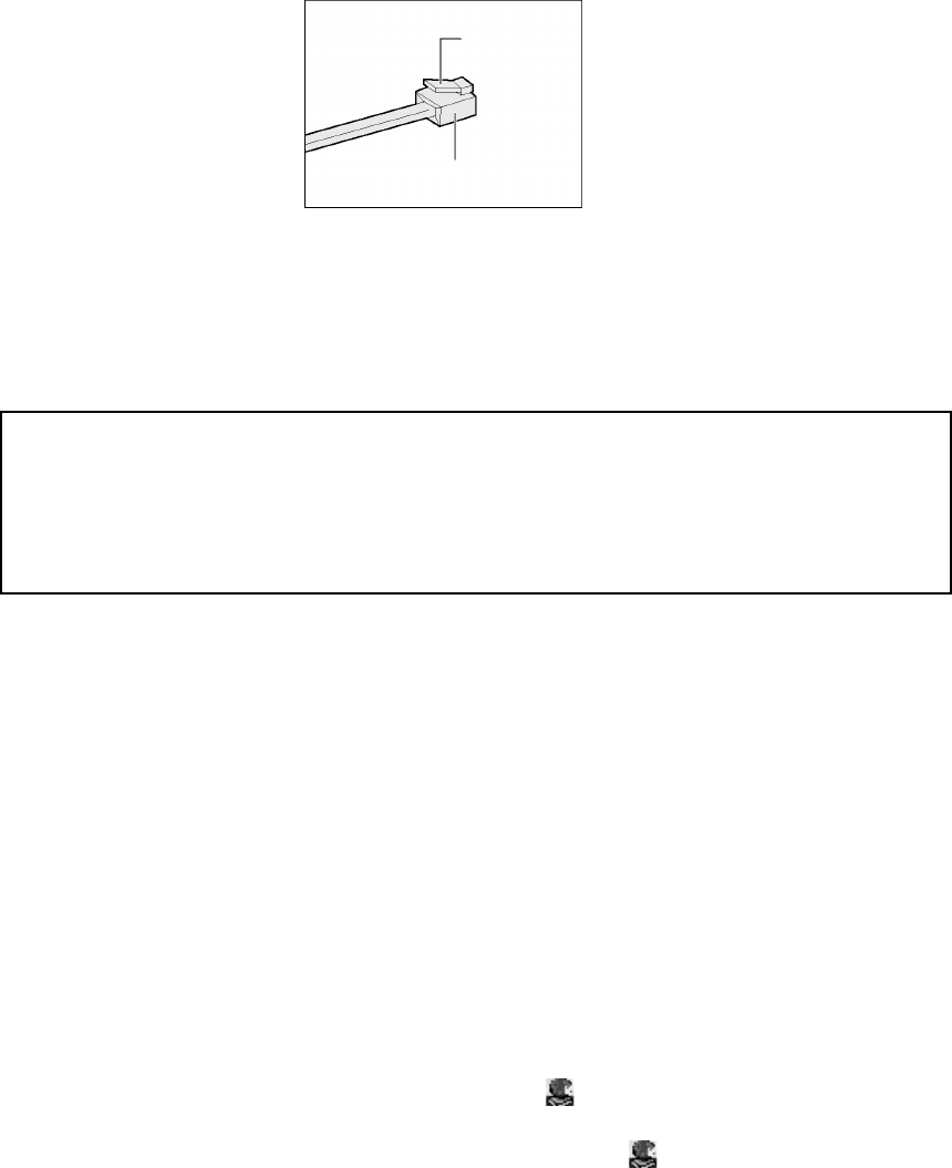
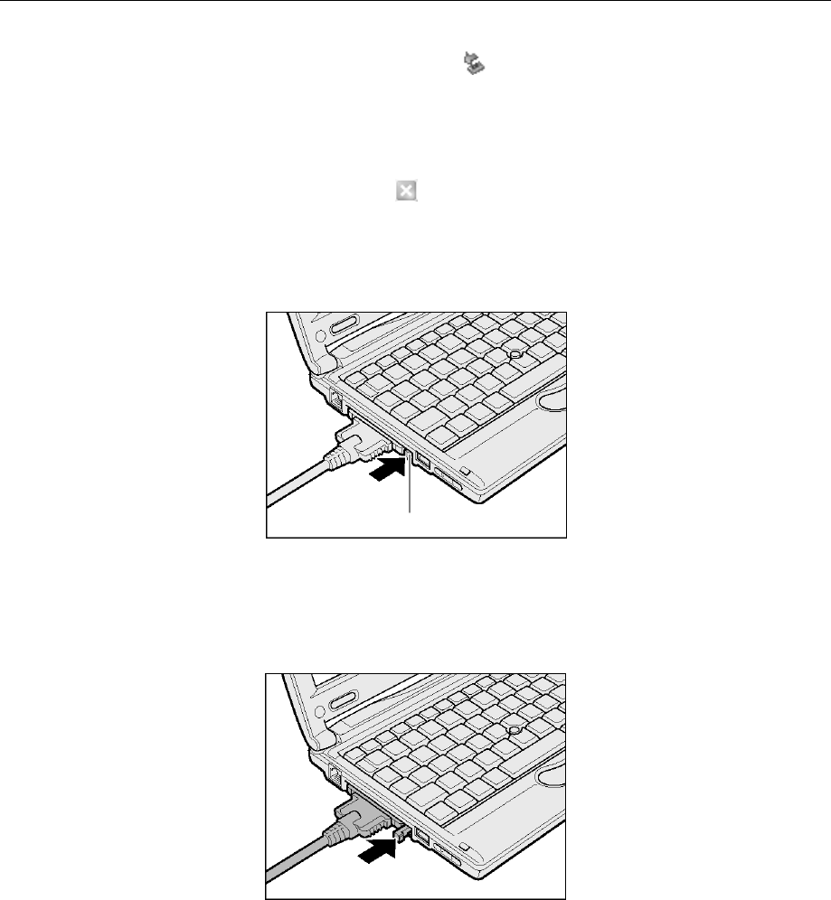
To Disconnect the Modular Cable
To disconnect the modular cable, press and hold the lock on the modular plug and pull it out
from the modular jack.
Lock
Modular plug
! Changing the region setting
The internal modem in your computer can be used in the following countries and regions:
Iceland, Ireland, U.S.A, U.A.E, U.K., Israel, Italia, India, Indonesia, Egypt, Estonia, Australia,
Austria, Oman, Netherlands, Canada, Korea, Greece, Kuwait, Saudi Arabia, Singapore,
Switzerland, Sweden, Spain, Sri Lanka, Slovakia, Slovenia, Thailand, Taiwan, Czech, China,
Denmark, Germany, Turkey, Japan, New Zealand, Norway, Pakistan, Hungary, Bangladesh,
Philippines, Finland, France, Bulgaria, Belgium, Poland, Portugal, Hong Kong, Malta,
Malaysia, South Africa, Morocco, Latvia, Lithuania, Luxemburg, Lebanon, Russia
As of April 2002
When using the modem overseas, use “Internal Modem Region Select Utility” for regional
settings.
When using your computer in Japan, be sure to use it in Japan mode. Use of the product in any
other mode is a violation of Telecommunications Business Law (Technical Standards).
NOTE:•Before starting “Internal Modem Region Select Utility”, be sure to log onto your
computer using the Administrator user account. An attempt to start the utility using
any user account other than the Administrator may cause an error message to
appear.
1. Click [Start] → [All Programs] → [TOSHIBA Internal Modem] → [Region Select
Utility].
The [Internal Modem Region Select Utility] icon ( ) appears on the Notification area.
2. Click the [Internal Modem Region Select Utility] icon ( ) on the Notification area.
The list of regions that the internal modem supports appears.
The currently selected region and the location name on the sub-menu are marked with the
check mark.

29
3. Click to select a region name or a location name.
If a region name is selected, new region information will be created after the region setup
for the modem and new location information will be used as the current location
information.
If a location name is selected, the region specified in its location information will be used
for the region setup for the modem and the selected location information will be used as the
current location information.
Other Settings
1. Right-click the [Internal Modem Region Select Utility] icon ( ) on the Notification
area and select an option from the menu.
• Settings
Click the check box to change the following settings:
Automatic start mode “Internal Modem Region Select Utility”
automatically starts at the system start-up and
the region setting is made for the modem.
Automatically display dial properties after
region selection. The [Phone and Modem Options] window
appears after region selection.
Select a region from the location setting The location name specified in the [Phone and
Modem Options] window appears in the sub-
menu of the region name. You can now select a
region using its location name.
Display a dialog if the region code of the
current location setting is inconsistent
between the modem and the telephony.
If the region setting of the modem is different
from the region code of the current location
setting specified on the [Phone and Modem
Options] window, a message dialog appears.
• Modem selection
The window for selecting the COM port number appears. When using the internal modem, no
change is required as the COM port number is automatically set.
• Dial properties
The [Phone and Modem Options] window appears.
30
6. LAN
1. LAN with Cables
Your computer is provided with the internal LAN device for broadband communications.
Connect an ADSL or cable modem to the LAN connector for broadband Internet connection. For
network devices and setting required for the broadband connection, contact your Internet
provider.
You can also connect a LAN cable to the LAN connector. Your computer will automatically
detect and switch between Fast Ethernet (100BASE-TX) and Ethernet (10BASE-T).
When connecting your computer to a 100BASE-TX (100 Mbps) network, be sure to use a cable
and connector of the category 5 (CAT5) type. You cannot use a cable of the category 3 type.
When connecting your computer to a 10BASE-T (10 Mbps) network, you can use a cable either
of the category 3 or 5 type.
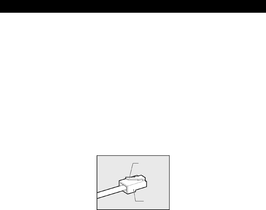
NOTES:•When plugging or unplugging a LAN cable, hold the cable plug. When unplugging
the cable, press and hold the lock on the plug. Do not pull the cable.
Lock
Plug
•Do not connect the modular cable to the LAN connector, as it may cause a
malfunction.
For connections of the network devices and the network settings, see “Windows Help”. When
connecting your computer to a network in your office or school, contact the network
administrator.

31
2. Wireless LAN
* For models with the wireless LAN capabilities only
The wireless LAN is a network with computers connected without LAN cables. Regardless of
the location of the modem or router, a computer can connect to the network from anywhere
within the wireless communications range.
Using a wireless LAN access point (optional), a wireless broadband environment can be
implemented with multiple computers.
Overview of the Wireless LAN
Your computer is provided with the following functions:
•Automatic selection among the transfer rates
Available transfer rates are 11, 5.5, 2 and 1 Mbps.
•Frequency channel selection (2.4 GHz band)
•Roaming among multiple channels
•Power management
•Data encryption based on the RC4 encryption algorithm defined in IEEE802.11.
! Types of the wireless LAN
The wireless LAN is a wireless network compliant with IEEE802.11. It supports the transfer rate
of up to 11 Mbps.
•The Wi-Fi (Wireless Fidelity) logo is certified by Wireless Ethernet Compatibility Alliance,
WECA.
The Wi-Fi logo indicates the wireless device that can communicate with third-party wireless
LAN devices compliant with IEEE802.11b.
•Use of Direct Sequence Spread Spectrum, DSSS, provides full compatibility with third-party
wireless LAN systems compliant with IEEE802.11b.

32
! Notes on use of the wireless LAN
•Place a wireless antenna for a wireless LAN in an obstacle-free location. To maximize the
wireless communication range, open the LCD and keep obstacles, including books and sheaves
of thick paper, away from your computer.
•The wireless LAN is a wireless product. For local wireless regulations, check with “User
Information”.
Types of the Wireless LAN Network
! Peer-to-peer workgroup
A method to build a temporary network in an environment without a wireless LAN access point,
such as Small Office/Home Office (SOHO). Setting a peer-to-peer workgroup allows you to
build a small wireless network. When devices, including computers, are located within the
communication range of one another, setting a peer-to-peer workgroup is the easiest and most
economical method to build a wireless network.
In this workgroup, you can exchange files using the function such as [File and Printer Sharing]
supported by the Microsoft network. It is convenient for sharing data or exchange files in a
family or among friends.
! Infrastructure network
A method to connect to a network and access all network facilities from wireless LAN devices
using the wireless access point. You can access both of the following networks:
[Standalone network]
A network that is built with the wireless access point only
[Infrastructure network]
A network topology where the wireless access point is included in the existing wired network
Basic Setup
To connect to a wireless LAN network, a setup appropriate to your network is required.
Windows XP is compatible with wireless LAN networks.
1. Click [Start] → [Control Panel].
2. Click [Network and Internet Connections].
3. Click [Set up or change your home or small office network].
The [Start Network Setup Wizard] window appears. Follow the on-screen instructions to
proceed.
33
Advanced Setup
The wireless LAN can be built in almost all network environments with the basic setup only.
When it is connected to the infrastructure network, you can also add advanced settings on the
[Change Settings] window.
1. Click [Start] → [My Computer].
2. Click [My Network] under [Others].
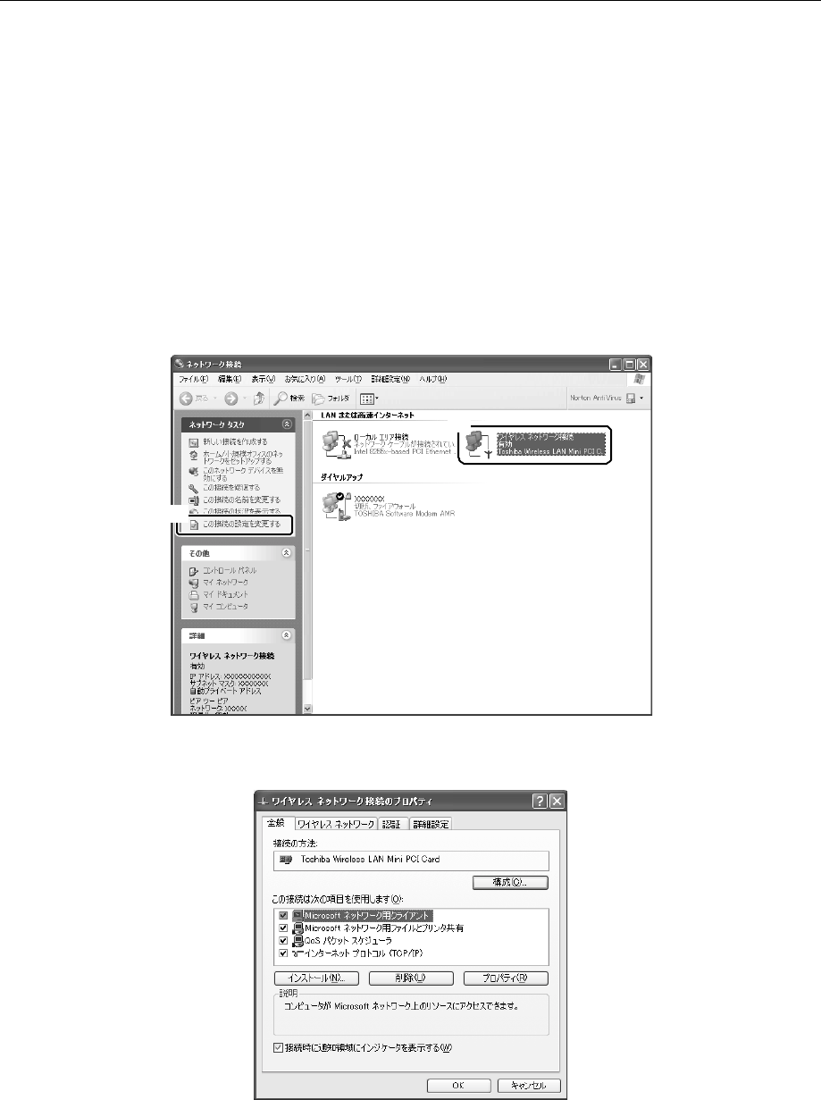
3. Click [Display network connections] under [Network tasks].
The [Network Connections] window appears.
4. Select [Wireless network connections] (1) and click [Change this connection
settings] (2) under [Network tasks].
(1)
(2)
The [Wireless Network Connection Properties] window appears.
5. Change the settings and click the [OK] button.
34
Using the Wireless LAN
This section describes how to view other computers on the network and the radio state of the
wireless LAN, and how to change the wireless LAN settings.
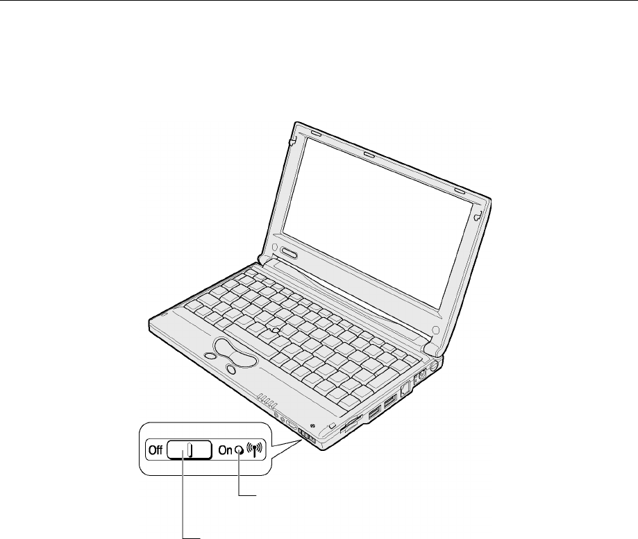
1. Slide the wireless communication switch on your computer to the right (On).
Wireless communication switch
Use this switch to enable/disable the wireless LAN function.
Slide the switch to the right (ON) to enable; to the left (Off) to
disable.
Wireless communication LED
The wireless communication LED lights and the wireless LAN becomes available.
When the wireless LAN is activated, your computer automatically looks for available
networks.
When an available network is found, a message appears on the bottom of the desktop.
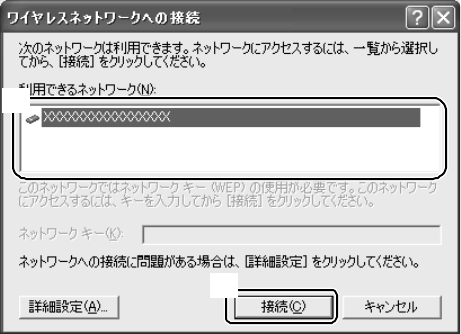
2. Click [Click here to display a list of available networks].
The [Connect to Wireless Network] window appears.
35
3. Select a desired network under [Available networks] (1) and click the [Connect]
button.
(1)
(2)
When a connection is established, the message “Wireless network connection is
established.” appears at the bottom of the desktop.
4. Click [Start] → [My Computer].
5. Click [My Network] under [Others].
6. Click [Display computers in the workgroup] under [Network tasks].
Devices available for connection through the wireless LAN, including computers, appear.
! To start help
For more information on the wireless LAN, see “Windows Help”.
36
Selecting a Network Device
With the “Network Device Switch”, you can select a desired device from among multiple
devices with the network feature.
You can also switch between the wired LAN and the wireless LAN using this switch. For
example, you can connect to the wired LAN in the living room and to the network through the
wireless LAN when you move to the study.
In addition, you can use this switch as the utility to enable/disable network devices.
For more information, see the help files for the “Network Device Switch”.
TIP:•Log onto your computer using the Administrator user account in order to activate
the network device switch.
1. Click [Start] → [All Programs] → [Network Device Switch] → [Network Device
Switch].
The [Network Device Switch] icon ( ) appears on the Notification area.
! To select a device
Before using the wireless LAN, turn on the wireless communication switch.
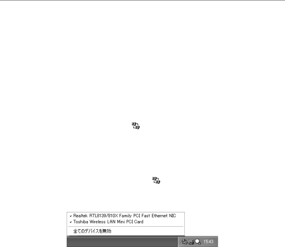
1. Click the [Network Device Switch] icon ( ) on the Notification area.
Available devices for your computer are listed.
2. Click the name of a device you want to use.
The device is selected and the enabled device is marked with the check mark. Other devices
are disabled.
TIP:•When you have changed the device, you may have to log onto the network again.

37
! Other settings
1. Right-click the [Network Device Switch] icon ( ) on the Notification area and
select an option from the menu.
•Automatic selection
When the cable is disconnected from the wired LAN, the wireless LAN is automatically
put in operation.
You can use this option when the wired LAN is in operation and the TCP/IP protocol is
in use.
•Disable (Enable)
Disables or enables the “Network Device Switch” function.
•Help
Displays the readme file for the “Network Device Switch”.
•Exit
Deactivates the “Network Device Switch”.
38
7. PC CARDS
The PC card slot of your computer can accommodate the Type II PC card (including the
CardBus-compliant card).
For more information on use of the PC card, see the manual that comes with your PC card.
TIP:•While the hard disk or CD-ROM of the PC card connection type is in operation, an
attempt to initiate communications or play back sounds may cause the following
phenomena:
- Decrease in the communication speed, disconnection of the communication line,
dialing failure
- Sound skips during playback
Notes on Insertion and Removal
Caution
- When using a PC card that does not support hot insertion, be sure to
turn off your computer before inserting or removing the PC card.
- Some PC cards may accumulate heat over long-time use. If the PC card
is hot, leave it for a while to let it cool down before removing it.
- Be sure to disable the PC card before removal. Removing the PC card
without disabling it may a fatal system error.
Inserting
1. If cable connection is required, connect a cable to the PC card.
2. Check the orientation of the card and insert it into the slot.
Gently push the card all the way to the end without applying excessive force. If the PC card
is not inserted all the way to the end, you may not be able to use the card or the card may be
damaged.
REFERENCE: For more information on PC card connection and setup, see the manual that
comes with your PC card.
39
Removing
1. Disable the PC card.
(1) Click the [Safe Hardware Removal] icon ( ) on the Notification area.
(2) Click [Remove XXXX (the PC card to remove) safely] in the menu.
(3) When the message “The ‘XXXX’ device can now be safely removed from the system.”
appears, click the [Close] button ( ).
2. Press the PC card eject button.
The eject button comes out.
Eject button
3. Press the PC card eject button again.
Press the button until it clicks.
The card comes out.
4. Grab the card end and pull out the card.
NOTE:•Do not pull the cable to pull out the card, as it may cause a malfunction.

40
8. SD CARDS
The SD memory card slot of your computer can accommodate the SD memory card of 8, 16, 32,
64, 128 and 256 MB, but not the multimedia card.
! Copyright protection
In accordance with the SDMI rules, the copyright protection technology is used for the SD card
to protect against illegal copying or playback of the digital music data. If copyright protection is
applied to the data imported with another computer, you cannot copy or play back the data with
your computer.
TERM:•SDMI (Secure Digital Music Initiative): Organization to standardize the technical
specifications for protecting the copyright of the digital music data
! Copyright
The copyright law states that your recording data cannot be used without permission from the
copyright holder except for personal use.
! Available memory capacity
The SD memory card can store data compliant with the SDMI standard that protects against
illegal copying and playback of the digital music data. The memory capacity of the SD memory
card is less than the indicated capacity because a part of the memory is used as the management
data area.
41
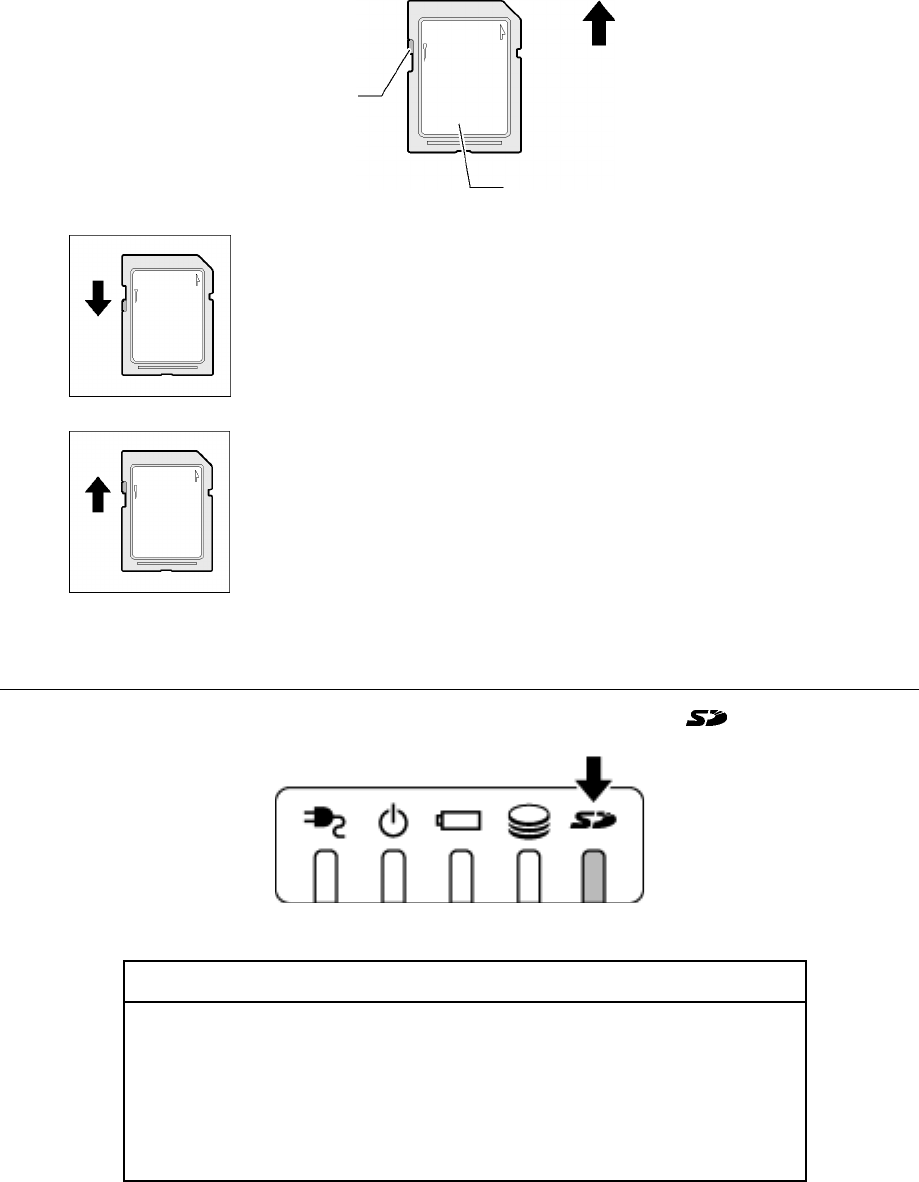
! Write-protect tab
The SD memory card is provided with the write-protect tab. By sliding this tab, you can protect
the data from being accidentally erased.
Label
Write-protect tab
Inserting direction
Write-protected
Slide the write-protect tab in the direction opposite to card insertion.
When the SD card is write-protected, you cannot write data onto the card but
can read from it.
Write-free
Slide the write-protect tab in the same direction as card insertion.
When the SD card is write-free, you can write/read data onto/from the card.
SD Memory Card Slot Indicator
While data access to the SD memory card is processing, the SD Card ( ) LED lights.
Caution
- When the SD Card LED is lit, do not turn off your computer, remove the
SD memory card, or move your computer, as it may damage the data or
the SD memory card.
- Gently insert the SD memory card without applying excessive force. If
the SD memory card is not correctly inserted, operations of your
computer may become unstable or the data in the SD memory card may
be corrupted.
42
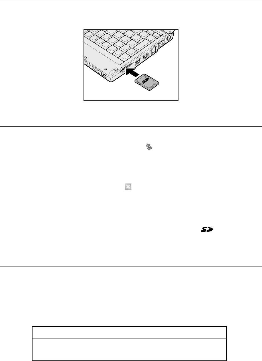
Inserting
1. Hold the SD memory card with its labeled side up and insert it into the card slot.
Insert the card all the way to the end.
Removing
1. Disable the SD memory card.
(1) Click the [Safe Hardware Removal] icon ( )on the Notification area.
(2) Click [Remove TOSHIBA SD Memory Card Drive safely] in the menu.
(3) When the message “The ‘XXXX’ device can now be safely removed from the system.”
appears, click the [Close] button ( ).
2. Push the SD memory card.
The card slightly comes out. Grab the card and pull it out.
NOTE:•Do not remove the SD memory card when the SD Card ( ) LED is lit, as it
corrupts the data contained in the card.
Formatting
Formatting is to write the basic information, including the track number and the head number,
onto the SD memory card and make the card available for use.
New SD memory cards are formatted in accordance with the SD memory card standard before
sale. If you want to reformat the SC memory card, use the device (digital camera, audio player,
etc.) with which you want the SD memory card. For information on formatting, see the manual
that comes with your device.
Caution
- Do not format the SD memory card on Windows (the [My Computer]
window), as it may make the card unavailable for use with other
devices, including a digital camera and an audio player.
NOTE:•Reformatting the SD memory card erases all the information stored in the card. Be
careful when reformatting SD cards that have been used.
43
9. EXTERNAL DISPLAY
Use the supplied RGB cable to display an external display. Before connecting the display, be
sure to turn off your computer.
Connecting
1. Turn off your computer.
2. Insert the mini-RGB cable plug into the mini-RGB connector.
Hold the plug with its arrow-marked side down to insert the plug.
When disconnecting, pull out the cable plug from the mini-RGB connector.
Mini-RGB connector
3. Insert the plug of the external display cable into the RGB connector at the end of
the mini-RGB cable.
Connect an external display and turn on your computer.

44
Selecting a Display Device
When an external display is connected to your computer, you can display
•on your computer’s LCD only (default).
•both on the external display and your computer’s LCD.
•on the external display only.
NOTES:•Do not change the display in the following cases, as it may erase data.
- during data read/write access
An error occurs. Wait until data access is complete.
- during communications
An error occurs. Wait until communications are complete.
•The display position or the display width on the external display may need
adjustment. In such a case, set the display position or the display width using the
controls provided with the external display.
TIPS:•If the power saving function turns off, press the Shift or Ctrl key or move the
Accupoint II. It may take about 10 seconds to return to the display but this is not an
error.
•If you play back a video file (AVI, MPEG, etc.) on the full screen using the
resolution of 1280
×
600 pixels, part of the image is not displayed.
•If you use the resolution of 1280
×
600 pixels, black bars (non-display areas) appear
at the top and bottom of the external display.
•The resolution of your computer’s LCD is 1280
×
600 pixels. To display on an
external display, use the one compatible with the resolution of 1280
×
1024 pixels.
If you use an external display not compatible with the resolution of 1280
×
1024
pixels, change the resolution of your computer’s LCD to suit the resolution of the
external display.
The number of colors of Monitor 2 is set to 256 colors by default. Change the
number of colors if necessary.
REFERENCE: For information on video mode, see “Appendix 1-2 Supported video modes”.
For changing the video settings, see “Online Manual”.
45
! Using the Fn + F5 keys
Press and hold the Fn key and press the F5 key to select a display.
LCD (LCD only)
LCD/CRT (LCD and external display)
CRT (External display only)
This option is selected regardless of the state
of the external display connection. Note that
nothing appears on your computer's LCD
when no external display is connected.
TIP:•If you cycle the power to your computer when an external display is connected and
selected for display, the image appears on your computer’s LCD.
Use the Fn + F5 keys to select the external display.
! Using the [Display Properties] window
1. Click [Start] → [Control Panel].
2. Click [Appearance and Themes].
3. Click [Display].
The [Display Properties] window appears.
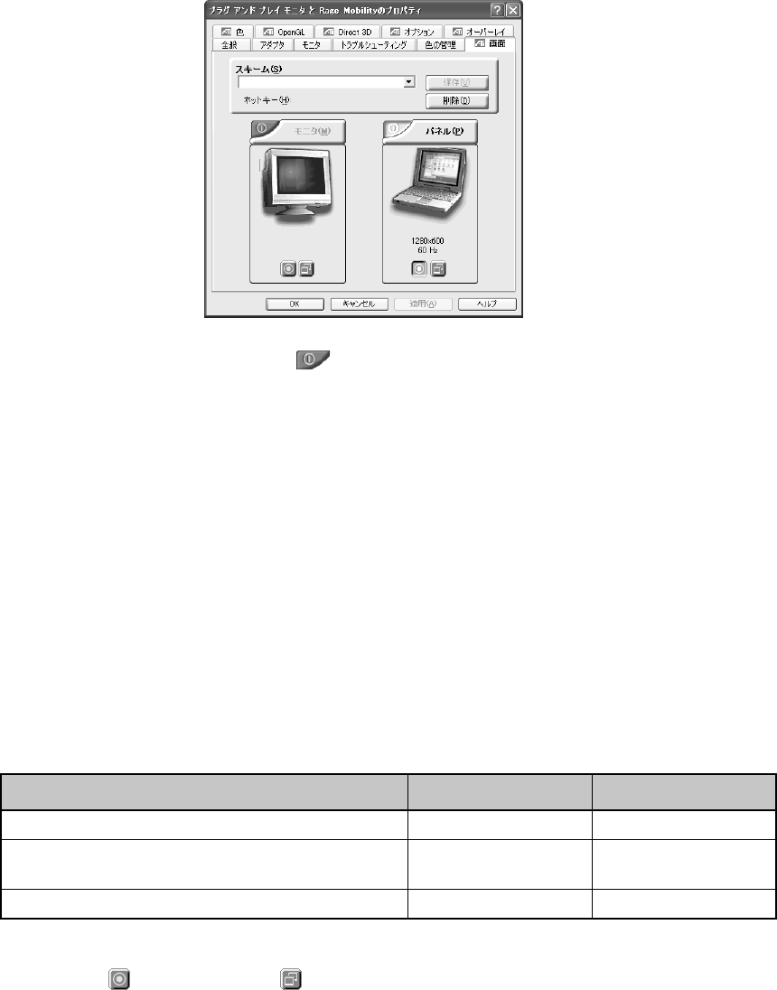
4. Click [Advanced] on the [Settings] tab.
The [Plug-and-play Monitor and Rage Mobility Properties] window appears.
46
5. Enable the device on the [Displays] tab.
Click the [Enable/Disable] button ( ) at the top left corner of the display device name to
select the device.
By default, your computer’s LCD (Panel) only is selected.
Follow the instructions below to select a display.
Your computer’s LCD (Panel) only
↓↑ Click the [Enable/Disable] button for [Monitor].
Both your computer’s LCD (Panel) and the external display (Monitor)
↓↑ Click the [Enable/Disable] button for [Panel].
External display (Monitor) only
The [Enable/Disable] button changes in color as listed below.
Monitor Panel
Your computer’s LCD (Panel) only Red Gray
Both your computer’s LCD (Panel) and the
external display (Monitor)* Green Green
External display (Monitor) only Gray Red
* When both your computer’s LCD and the external display are selected, you can use the
Primary ( ) and Secondary ( ) buttons to select a device for video display.
47
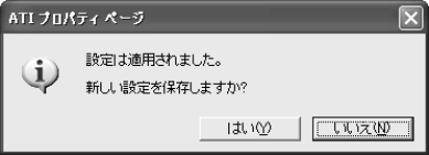
6. Click the [OK] button
The following window appears.
TIP:•If nothing appears on the external display within 15 seconds, the display selection is
discarded.
7. Click the [Yes] button.

48
10.OPTIONAL DEVICES
For optional devices that are not described in this manual, see the manual that comes with the
device.
The procedures to connect and disconnect optional devices vary. Be sure to read the respective
sections in advance.
Caution
- When connecting an optional device that does not support connection
and disconnection while power is supplied, be sure to turn off your
computer, unplug the power cord, and remove the battery pack in
advance.
NOTES:•Do not submit your computer to drastic changes in temperature even within the
appropriate temperature and humidity ranges to avoid condensation. Extra care is
needed in the winter.
•Connect or disconnect optional devices in a location with little dust and not exposed
to direct sunlight.
•Do not connect or disconnect optional devices in a location of extremely high/low
humidity.
•Do not connect or disconnect optional devices in a location with a change of static
electricity.
•Do not remove any screws not mentioned in the manual.
•Use a screwdriver that fits the shape and size of the screws.
•Disassembly and modification to your computer will void the warranty and support.
•Not all optional devices are assured for compatibility, as it is impossible to check all
of them.
•Do not carry your computer when optional devices are connected.
! Notes on connecting cables to your computer
When connecting cables to your computer, observe the following:
•Check the orientation of the cable connector before connecting it to your computer. Excessive
force to the connector will break or bend the connector pins.
•If the cable connector is equipped with screws, connect the cable to your computer and fasten
the screws to avoid disconnection of the cable.
49
11.MEMORY EXPANSION
You can add memory cards of up to 256 MB to the additional memory slot. Use the additional
memory cards tested and found compatible with your computer. Adding incompatible memory
cards may cause a failure to start the system or unstable operations of your computer.
Notes on Adding/Removing the Memory Card
Warning
- Never disassemble the components not mentioned in this manual. Your
computer has many high-voltage components and it is dangerous to
touch them.
Caution
- Keep any metal objects, such as staples and paperclips, and liquid,
such as coffee, out of your computer, as it may cause a shortcircuit or
fumes. If such an object gets inside your computer, remove the battery
pack, keep your computer powered off, and ask your sales dealer or the
nearest maintenance service to inspect it.
- Before adding or removing a memory card, be sure to turn off your
computer, unplug the AC adapter, and remove the battery pack. Adding
or removing a memory card while your computer is powered may cause
an electric shock or a malfunction.
- Do not add or remove a memory card in the following cases, as it may
cause burns, an electric shock, or a malfunction.
• when your computer is on Standby
• immediately after your computer is turned off
Before adding or removing a memory card, it is recommended to
leave your computer at least 30 minutes after it is turned off.
- Do not touch any connectors on your computer, including the memory
connectors. If the memory connector is covered with dust, the memory
will not properly function.
NOTES:•Use a No. 1 size bit Phillips screwdriver of to remove screws.
•Do not strongly press, bend, or drop additional memory cards.
•Do not add or remove an additional memory card when your computer is on
Standby or in Hibernate as it clears the Standby or Hibernate mode. It may also
change or erase the stored data.
50
! About static electricity
The additional memory card is a precision electronic component and may be seriously damaged
by static electricity. As a human body is slightly charged with static electricity, be sure to
discharge the static electricity before adding an additional memory card. You can discharge the
static electricity by touching a nearby metal object.
Adding
1. Save your data, shut down Windows, and turn off your computer.
2. Remove the AC adapter and cables from your computer.
3. Turn your computer upside down and remove the battery pack.
REFERENCE: For more information on the battery pack, see “1-3 Replacing the battery
pack” in Chapter 4.
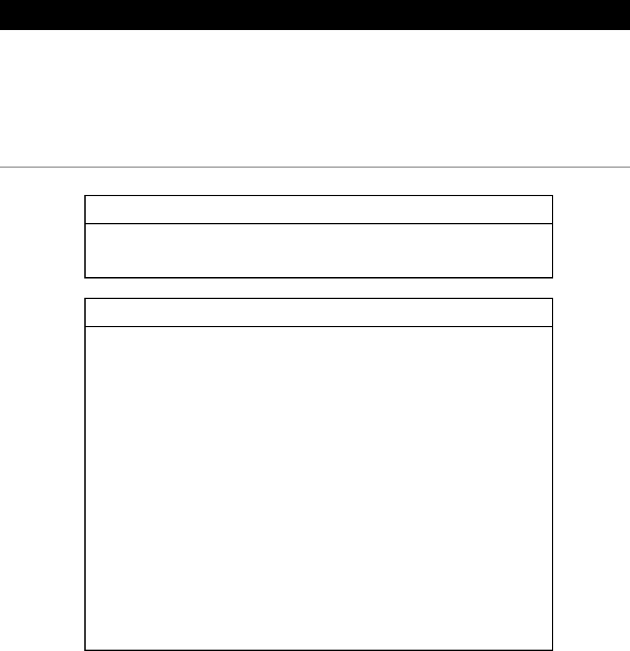
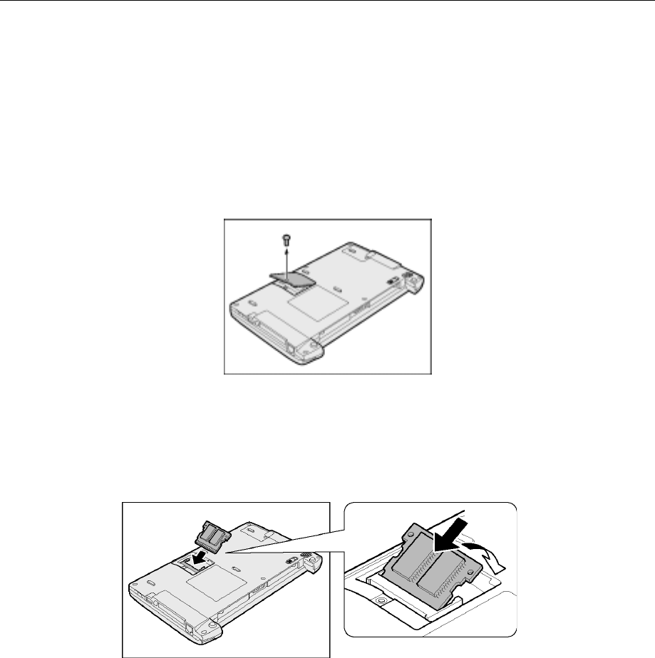
4. Remove the screw from the additional memory cover and remove the cover.
5. Insert the additional memory card diagonally into the connector in the additional
memory card slot (1) and push down the card until it is secured (2).
Align the notches on the additional memory card with the hooks of the additional memory
slot and push the card all the way down. If the hooks are tight, use a pen to push them open.
(1)
(2)
51
6. Replace the additional memory cover and fasten the screws that you removed in
step 4.
Make sure that the additional memory cover is firmly closed.
7. Replace the battery pack.
When you turn on your computer, the total memory capacity is automatically recognized. Check
if the total memory capacity is correct.
REFERENCE: For checking the memory capacity, see “Checking the memory capacity” to be
described later in this section.
Removing
1. Save your data, shut down Windows, and turn off your computer.
2. Remove the AC adapter and cables from your computer.
3. Turn your computer up side down and remove the battery pack.
REFERENCE: For more information on the battery pack, see “1-3 Replacing the battery
pack” in Chapter 4.
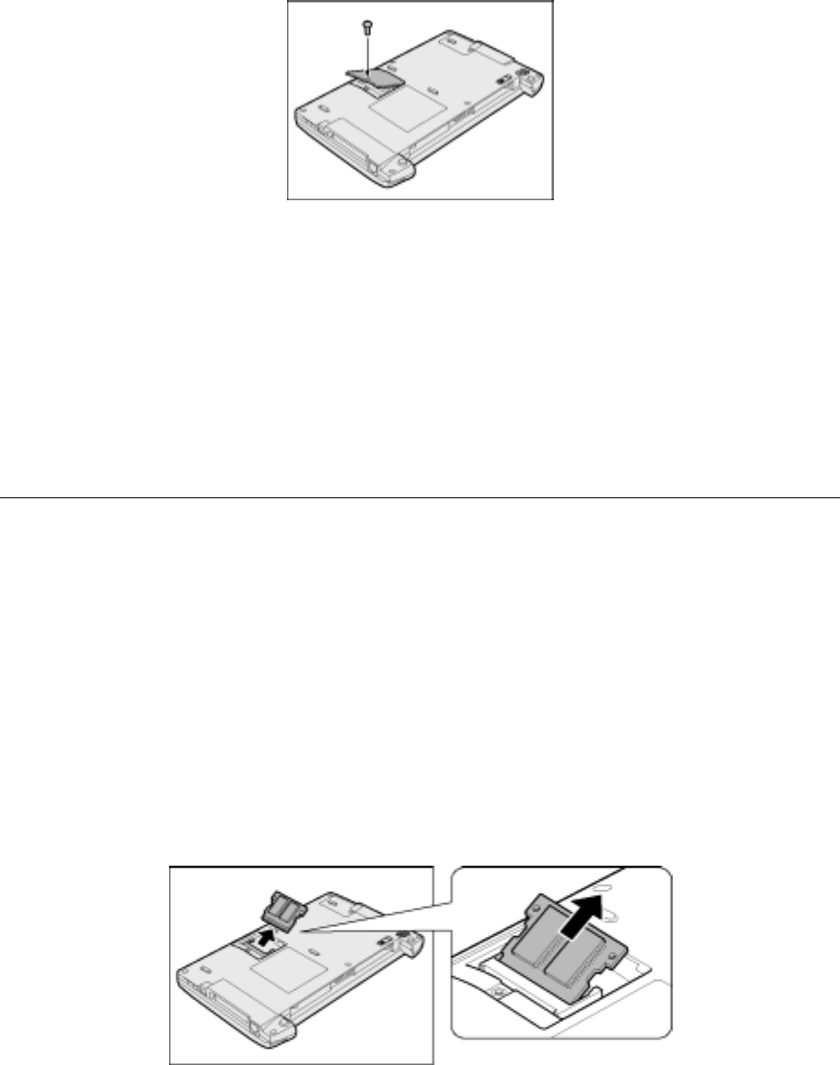
4. Remove the screw from the additional memory cover and remove the cover.
5. Use a pen to push open the left and right hooks securing the additional memory
card and remove the card from your computer.
Pull out the additional memory card that is diagonally raised.

52
6. Replace the additional memory cover and fasten the screws that you removed in
step 4.
Make sure that the additional memory cover is firmly closed.
7. Replace the battery pack.
When you turn on your computer, the total memory capacity is automatically recognized. Check
if the total memory capacity is correct.
REFERENCE: For checking the memory capacity, see “Checking the memory capacity” in
this section.
Checking the Memory Capacity
TIP:•As the system uses approximately 16 MB of the main memory, the memory capacity
displayed on the [PC Diagnostic Tool] or [System Properties] window is less than
the actual capacity.
! Checking with [PC Diagnostic Tool]
(1) Click [Start] → [All Programs] → [Toshiba Utilities] → [PC Diagnostic Tool].
(2) Click the [View the basic information] button.
(3) Check the value for [Memory].