Toshiba Cs3910Bh Specifications ( CS3910BH\211p\225\266\216d\227l\217\221)
CS3910BH cs3910bh
2014-12-13
: Toshiba Toshiba-Cs3910Bh-Specifications-131738 toshiba-cs3910bh-specifications-131738 toshiba pdf
Open the PDF directly: View PDF ![]() .
.
Page Count: 19

D4134051A
High-Resolution CCD Camera
Model CS3910BH
Specifications
Contents
1.PRODUCT DESCRIPTION 6
2.FEATURES 6
3.COMPONENTS 6
4.FUNCTION 7
5.SPECIFICATIONS 12
6.TIMING CHART 15
7.EXTERNAL-VIEW DRAWINGS 18
1
D4134051A
BEFORE USE - GENERAL SAFETY INSTRUCTIONS
This specifications contains important information for the operator (user) and/or people in the
vicinity to avoid personal injury, or property damage.
• Prior to use, read this specifications carefully to fully understand its instructions for correct use.
• After reading, keep operation manual near the equipment for future reference.
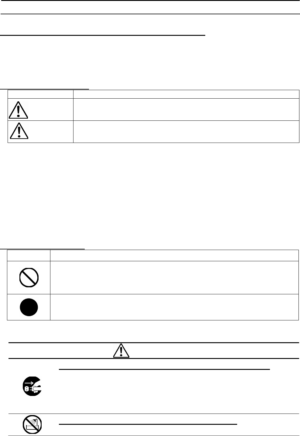
WARNINGS & CAUTIONS
Indication Meaning
WARNING
This indicates the existence of a hazard that death or catastrophic bodily
injury(*1) may result from improper use.
CAUTION
This indicates the existence of a hazard that bodily injury(*2) or property
damage(*3) may result from improper use.
Notes
*1 Catastrophic bodily injury means loss of eyesight, burns (high and low temperatured), shock,
fracture, poisoning, etc. which leaves a sequela and repuire hospitalization or prolonged
treatment.
*2 Bodily injury means injuries, burns and electric shock which does not require hospitalization
or prolonged treatment.
*3 Property damage means extended harm to home, household effects, domesticated animals, and
pets.
Graphic symbol definitions
Indication
Meaning
This mark indicates a prohibited action that must not be carried out. The actual
prohibited action is indicated in the symbol or nearby graphically or described in
text.
This mark indicates a mandatory action that must not be carried out. The actual
instruction is indicated in the symbol or nearby graphically or described in text.
●Handling Precautions
WARNING
Stop operation immediately when any abnormality or defect occurs.
Use during an abnormal condition; such as emitting smoke, burning odors,
damage from dropping invasion of foreign objects, etc. may cause fire and/or
electric shock. Be always sure to disconnect the power plug from the electrical
outlet (socket) at once and contact your dealer.
Do not operate in places with possibility of becoming wet.
This may cause fire and/or electric shock.
Important Safety Precautions
2
D4134051A
Do not repair, disassemble and/or modify by yourself.
This may cause fire and/or electric shock. Be always sure to contact your dealer
for internal repair, check and cleaning of the product.
Don’t place things or materials on the unit.
Ingress of foreign materials such as metallic things and liquid into the unit may
cause a fire or an electric shock.
Do not put the product in an unstable, slanting and/or vibrated place.
Drop and/or fail of the product may cause injury.
Do not touch the power cord or other connection cables during a
thunderstorm.
This might cause electric shock.
Use the specified power supply.
Use of an unspecified power supply may result in fire or electric shock.
Do not be handled roughly, damaged, fabricated, bent forcefully, pulled,
twisted, bundled, placed under heavy objects or heated the power cord ,
connection cable.
Otherwise, fire or electric shock may result.
CAUTION
Note the following instructions when installing.
-Do not wrap the product in an inflammable material, such as cloth.
-Do not put the product in a narrow space, since the heat generated from the
product may be difficult to emanate.
If you do not follow the above, the heat generated by the product may cause
fire.
Avoid setting in humid, smoky, vaporized or dusty places. A fire or an
electric shock may occur in such places.
This may cause fire and/or electric shock.
Do not put the product in direct sunshine and/or high temperature.
The temperature inside the product may cause fire.
Use the specified DC power cable or connection cable.
Otherwise, a fire or an electric shock may occur.
Turn OFF the power in the case of connection.
Turn OFF the power in the case of connection of power cable or connection
cable.
Otherwise, an electric shock or a malfunction may occur.
Do not expose its camera head to any intensive light (such as direct
sunlight).
Otherwise, its inner image pickup device might get damaged.

3
D4134051A
Avoid short-circuiting signal output.
Otherwise, a malfunction may occur.
Avoid giving a strong shock against the camera body.
It might cause a breakdown or damage.
If your camera is used in a system where its camera connector is subjected to
strong repetitive shocks, its camera connector is possible to break down. If
you intend to use your camera in such a situation, if possible, bundle and fix
a camera cable in the place near the camera, and do not transmit a shock to
the camera connector.
Ask your dealer to perfom a periodical check and internal cleaning
(approx. once every five years).
Dust inside the product may cause fire and/or trouble. For check and cleaning
cost, please consult your dealer.
DISCLAIMER (LIMITED WARRANTY)
We disclaim any responsibility and shall be held harmless for any damages or losses incurred by
the user in any of the following cases;
Fire, earthquake or any other act of God; acts by third parties; misuse by the user, whether
intentional or accidental; use under extreme operating conditions.
Malfunction or non-function resulting in indirect, additional or consequential damages,
including but not limited to loss of expected income and suspension of business activities.
Incorrent use not in compliance with instructions in this instruction specifications and manual.
Malfunctions resulting from misconnection to other equipment.
Repairs or modifications made by the user or caused to be made by the user and carried out by
an unauthorized third party.
Notwithstanding the foregoing, Teli’s liabilities shall not, in any circumstances, exceed the
purchase price of the product.
About the item which does not have a publication in the specifications and manual of this
product, it considers as the outside for a guarantee.

4
D4134051A
RESTRICTION FOR USE
Should the equipment be used in the following conditions or environments, give consideration
to safelty measures and inform us of such usage:
1. Use of the equipment in the conditions or environment contrary to those specified, or use
outdoors.
2. Use of the equipment in applications sxpected to cause potential hazard to people or
propety, which require special safety measures to be adopted.
This product can be used under diverse operating conditions. Determination of applicability of
equipment or devices concerned shall be determined after analysis or testing as necessary by
the designner of such equipment or devices, or personnel related to the specifications. Such
designer or personnel shall assure the performance and safety of the equipment or devices.
This product is not designed or manufactured to be used for control of equipment directly
concerned with human life (*1) or equipment relating to maintenance of of public
services/functions involving factors of safety (*2). Therefore, the product shall not be used for
such applications.
(*1): Equipment directly concerned with human life refers to.
- Medical equipment such as life-support systems, equipment for prerating theaters.
- Exhaust control equipment for exhaust gases such as toxic fumes or smoke.
- Equipment mandatory to be installed by various laws and regulations such as the Fire
Act or Building Standard Law
- Equipment related to the above.
(*2) : Equipment relating to maintenance of public services/functions involving factors of
safety refers to.
- Traffic control systems for air transportations, railways, roads, or marine
transportation
- Equipment for nuclear power generation
- Equipment related to the above

5
D4134051A
CAUTIONS ON USE
Carefully handle the units.
Do not drop, or give a strong shock or vibration to the camera. This may cause problems. Treat
the camera cables carefully to prevent cable problems, such as cable breakdown and loosened
connections.
Operating ambient temperature and humidity.
Do not use the camera in places where temperature and humidity exceed the specifications.
Picture quality will lower and internal parts may be damaged.
Be particularly careful when using in places exposed to direct sunlight. When shooting in hot
places, depending on the conditions of the object and the camera (for example when the gain is
increased), noise in the form of vertical strips or white dots may occur. This is not a
malfunction.
Restriction for the lens combination
This camera might form a ghost to image area depending on the combination of a lens and an
illumination with this camera. But this is not a failure of this camera. Therefore, please check
the combination of the lens and the illumination with this camera when use.
When mounting a lens, take extra caution so that the lens is not tilted, nor does flaw exist at
the lens-mount-screw part. Also check to confirm that no dirt nor other foreign object is put
inside
Improper mounting might cause the parts to become locked.
Do not shoot under intense light.
Avoid intense light such as spot light on part of the screen because it may cause blooming or
smears. If intense light falls on the screen, vertical stripes may appear on the screen, but this is
not a malfunction.
Do not expose the camera’s image-pickup-plane to sunlight or other intense light directly.
Its inner CCD (charge-coupled device) might be damaged.
Moire
When thin stripe patterns are shot, stripe patterns that are not actually there (moire) may
appears as interference stripes. This is not a malfunction.
Undesirable noise
If the camera or the cables are located near something which emit strong magnetism or near
something which emit strong electric wave, undesirable noise may appear on the screen. In
such a case, try to change the location of the camera or the cable wiring.
Handling of the protection cap
When the camera is not in use, put a lens-cap onto the camera head for protection of the
image-pickup-plane.
When not using the camera for a longtime.
Stop supplying power for safety.
When cleaning the camera
Always turn off the power and clean with a piece of soft dry cloth.
To remove stubborn stains, use a soft cloth soaked in diluted acid-free detergent. Do not use
alcohol, benzine, thinner, etc. If used, coating and printed letters may be discolored.
In case the image-pickup-plane should be settled with fine dust, dirt, or scratched, ask your
dealer for technical advice.
Wastes of this product should be separated and discarded in compliance with the various
national and local ordinances.
6
D4134051A
1. PRODUCT DESCRIPTION
Model CS3910BH is an integrated-(one-body)-type monochrome CCD camera with a 2/3-type
all-pixel-data-read-out CCD featuring high resolution.
2. FEATURES
(1) High resolution
CS3910BH features an high picture resolution through the adoption of a MEGA-pixel CCD (Total
pixel number: 1,500,000 Active pixel number: 1,450,000 [1,392(H)×1,040(V)]).
(2) Square-grid Pattern CCD
Pixels in this CCD are aligned in a square grid pattern. This makes it easier to perform computation
correctly for image processing use.
(3) Full-frame Shutter
As data in all pixels are read out even under RTS mode, images with no deterioration in vertical
resolution are obtained.
(4) Random Trigger Shutter (RTS)
Random trigger shutter, which starts light-exposure in synchronization with external trigger signal,
is built in. This function enables the camera to capture images at any given timing. Shutter speed is
selectable among 8 scales, from 1/30s through 1/10000s.
(5) Digital Output
Digital format output (EIA-644 single channel 10 bit) is available.
(6) External-sync Operation
Upon receiving external HD/VD IN, the camera automatically switches into ex-sync operation.
(7) All pixel read out mode (Normal mode)
This model can readout all pixel data (effective area) in 1/15 second.
(8) High speed draft mode
The High-speed scanning (1/60 frame/second) is available by using high-speed reading-out method
to read out 2 lines in 8 lines. Output is 267 lines.
(9) Partial-scan Mode
This model can readout pixel data in partial-scan format. (Screen center 1/2)
(10) AGC
With AGC (Automatic Gain Control) function, the camera can obtain the optimal image even if the
amount of incoming light (approx.4 times) fluctuates.
(11) Multiple Shutter
This model can capture images at any given timing cued by ex-trigger signal input, then outputs
accumulated video images at a set timing.
3. COMPONENTS
(1)Camera body …………………………………………1
(2)Accessories
Operation manual …………………………………………1
(3)Option
DC IN Cable …………………………Model CPRC3700
Digital cable …………………………Digital video cable
Tripod fixing metal
7
D4134051A
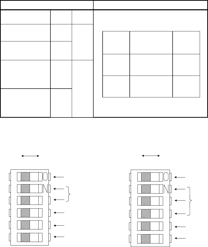
4. FUNCTION
The settings of each mode can set with rear-panel and inner DIP-switches.
*1: The shutter-speed selectable with inner DIP switches 2 through 4.
*2: ON / OFF selectable with inner DIP SW 1.
(1) Read out mode setting
Change internal Dip SW1(Factory setting: OFF)
OFF: 15Hz All Pixel Data Readout Mode (Normal mode)
ON: 60Hz High-Speed draft mode (As vertical 2 lines in 8 lines read out at the same timing
under this mode, vertical resolution is reduced to 1/4)
SW1-2
ON
OFF
ON
OFF
SW1-3
OFF
ON
・Random Trigger
Shtter
・Multiple-shutter
FIX mode
Shutter OFF
Nomal Shutter
・Random Trigger
Shtter
・Multiple-shutter
pulse mode
Mode
Function
Rear-panel DIP-switches
※1
※1
Partial-scan
(SW1-5)
Draft
(※2)
AGC
(SW1-1)
OFF OFFOFF
ON ONON
ONOFF
SW2 Inner-SW
1
2
3
4
5
6
DRAFT MODE
SHUTTER SPEED
NC(OFF Fixed)
NC(OFF Fixed)
ONOFF
SW1 Rear-panel DIP-SW
1
2
3
4
5
6
AGC ON/OFF
SHUTTER MODE
PARTIAL SCAN
ON/OFF
NC(OFF Fixed)
NC(OFF Fixed)
8
D4134051A
(2) Shutter Speed setting
Internal DIP switch from 2 to 4)
Shutter speed is 1/15s fixed when Shutter mode is normal shutter.
SW2-2 SW2-3 SW2-4 Shutter
speed
OFF OFF OFF 1/30
ON OFF OFF 1/60
OFF ON OFF 1/125
ON ON OFF 1/250
OFF OFF ON 1/1000
ON OFF ON 1/2000
OFF ON ON 1/4000
ON ON ON 1/10000
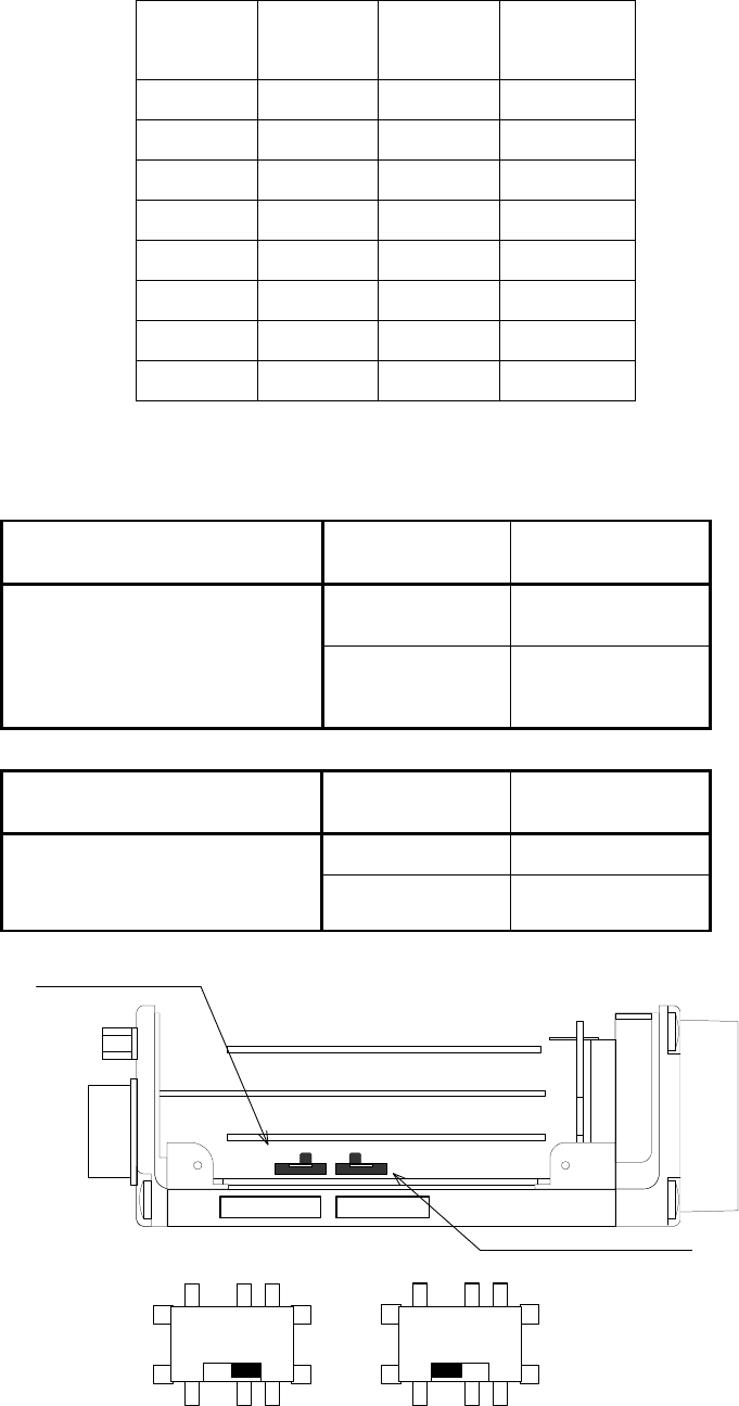
(3)External sync setting(HD/VD)
(a)SW1
Function (indication) Switch
selection
Function
selection
DATA DATA OUT
CONNECTOR
External sync connector
selection
(DATA ⇔ DCIN) DCIN DC IN/SYNC
CONNECTOR
(b)SW2
Function (indication) Switch
selection
Function
selection
IN Input
External sync input/output
selection
(IN ⇔ OUT) OUT Output
HD・VD
connector selection
PROCESS
TIMING
CPU
REG
SW1
HD・VD IN / OUT selection
SW2
DATA ⇔ DCIN IN ⇔ OUT
DC IN/SYNC Connector side
SW1
HD/VD IN side
SW2
9
D4134051A
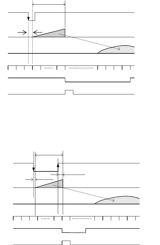
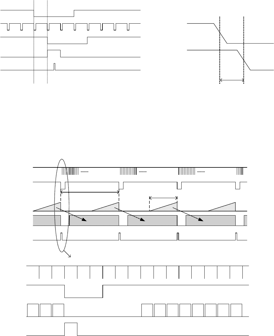
(4) RTS (Random Trigger Shutter) Pulse Control
The camera goes into RTS (Random Trigger Shutter) mode when TRIG terminal voltage is in
HIGH (More than 1V), and starts light-exposure at the falling edge timing. Under FIX mode, the
exposure-time is controlled with inner DIP switch settings. Under PULSE mode, the exposure-time
is determined by pulse length. The exposure-time control is done in 1H steps. Be sure to set the
pulse length longer than 1H (=Approximately 62.5 micro s). After video-output, it goes back into
normal operation (= inner DIP switches) if the TRIG terminal voltage stays in LOW.
The exposure starts at the next HD timing immediately after TRIG IN.
Video output timing
-1 Fix mode
*The VD is output in sync with the next HD after light-exposure
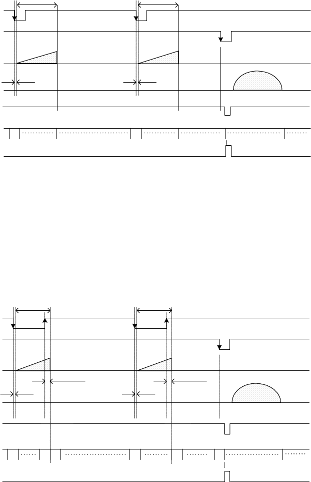
-2. Pulse mode
*The VD is output in sync with the next HD after light-exposure
CCD
(Exposure)
Exposure-time
(Setting with TRIG pulse interval +approx 15 micros)
TRIG
VIDEO
OUT
HD
VD
WEN
20μs
VIDEO
OUT
CCD
(Exposure)
Exposure-time (Setting
with inner DIP SW)
TRIG
HD
VD
WEN
approx.5micro s
approx.5micro s
10
D4134051A
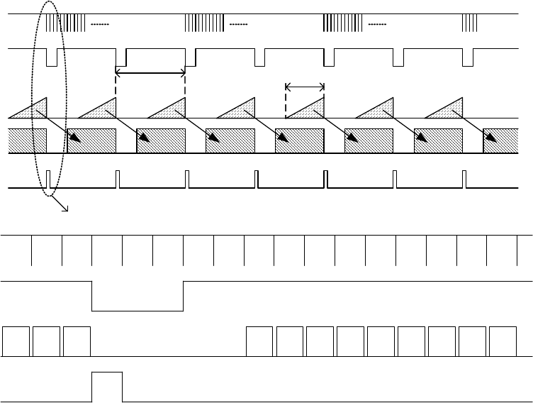
(5) Multiple-shutter Mode Setting
Exposure is done during the one frame period which comes immediately after TRIG IN. Images are
output at the readout signal (E.VD) timing. If the exposure is made more than one time before the
readout signal input, superposed images are output. After video-output, it goes back into the normal
operation (= shutter OFF) if the TRIG terminal voltage stays in LOW for 2V or longer consecutively,
regardless of which RTS mode is currently set in.
-1 Fix mode
-1 Pulse mode
A+B
A B
20μs 20μs
Exposure-time
(Setting with TRIG pulse interval + approx 15 micros)
TRIG
CCD
(Exposure)
E.VD
VIDEO OUT
HD
WEN
VD
approx.5micros approx.5micros
Exposure-time
(Setting with TRIG pulse interval + approx 15 micros)
A+B
A
Exposure-time
(Setting with inner DIP SW)
TRIG
CCD
(Exposure)
E.VD
VIDEO OUT
HD
B
WEN
VD
approx.5micros
Exposure-time
(Setting with inner DIP SW)
approx.5micros

11
D4134051A
(6) Partial-scan Mode Setting
The partial-scan ON/OFF selection is made via the rear SW1 DIP5 (Initial factory setting: OFF)
OFF: Normal mode
ON: 1/2 --- Screen-center 1/2 readout
◎ Total line 1046 line
Screen half-center read out
Opening pixel 271line
Opening pixel 487line
Opening pixel 280line
Normal-speed Transfer
High-speed Transfer
VIDEO OUT
(Normal)
VIDEO OUT
High-speed
Transfer
Normal-speed
Transfer
(Center1/2)
◎ Scan Range 523 line
High-speed Transfer 14line
Normal-speed Transfer
487line
Total = 523line
approx 32.3Hz
Empty Transfer(BLK) 2line
High-speed
Transfer
High-speed Transfer
Empty Transfer(BLK) 2line
High-speed Transfer 14line

12
D4134051A
5. SPECIFICATIONS
Model CS3910BH
[Electric specification]
Image sensor Interline CCD
Total pixel 1434(H) x 1050(V)
Active pixel 1392(H) x 1040(V)
Unit cell size 6.45(H) x 6.45(V) micrometer m
Optical size Equivalent to 2/3 inch image pickup tube
Scanning system Non-interlace
Aspect ratio 4:3
Sync system Internal / External automatic switchover
Illumination 200 lx (F8 3200K)
Gamma correction Gamma = 1.0(Fixed)
Video output Digital output: EIA-644
Data: 10bit (28.63636MHz)
Scanning frequency 15.29Hz (All pixel data read-out mode) or
60.37Hz (High-speed draft mode)
AGC +/- 6dB
Power source DC12V +/- 10 percent
Power consumption Approximately 2.7W
S/N 50dB(p-p/rms) (Under normal mode)
[Electric shutter specification]
Shutter speed 8 scales from 1/30s through 1/10000s
RTS Random Trigger Shutter
ON/OFF selectable (factory setting: OFF)
Fix mode --- Exposure-time determined by E shutter-speed
Pulse mode --- Exposure-time determined by pulse width
Partial scan ON/OFF selectable (factory setting: OFF)
ON --- Screen center 1/2 readout
Multiple shutter ON/OFF selectable (factory setting: OFF)
Fix mode --- Exposure-time determined by E shutter-speed
Pulse mode --- Exposure-time determined by pulse width
[Internal sync, signal specification]
H drive frequency 28.63636MHz+/-100ppm
Scanning frequency H: 15.998kHz+/-100ppm
V: 15.29Hz+/-100ppm (All pixel data read-out mode)
60.37Hz+/-100ppm (High speed draft read-out mode)
[External sync, signal specification]
External sync signal
HD TTL level, Negative, Input impedance: 10k-ohm
Repeating frequency 15.998kHz +/- 1 %
Pulse width: Longer than 5 micro s
VD TTL level, Negative, Input impedance: 10k-ohm
Repeating frequency 14.98Hz +/- 1 percent
Pulse width: Over 1H(62.5 micro s)
13
D4134051A
Trigger signal TTL level, Negative
Input impedance: 10k-ohm
Pulse width: Over 1H(62.5 micro s)
Multiple-shutter readout signal
TTL level, Negative
Input impedance: 10k-ohm
Pulse width: From 62.5 micro s through 10ms
[Sync output signal specification]
Output signal
WEN 4V(p-p), Positive, Pulse width: 1H (62.5 micro s)
HD [Output from DATA OUT]
EIA RS644 (LVDS)
Driver output voltage: +/- 350mV
(Differential output) / 100-ohm
VD [Output from DATA OUT]
EIA RS644 (LVDS)
Driver output voltage: +/- 350mV
(Differential output) / 100-ohm
CLOCK [Output from DATA OUT]
EIA RS644 (LVDS)
Driver output voltage: +/- 350mV
(Differential output) / 100-ohm
[Mechanical dimensions]
(1) Lens mount C mount
(2) External dimension 49(W) x 35(H) x 98(D)mm
(3) Weight Approx. 170g
(4) Chassis GND/ Isolation Conduct from circuit GND and Chassis
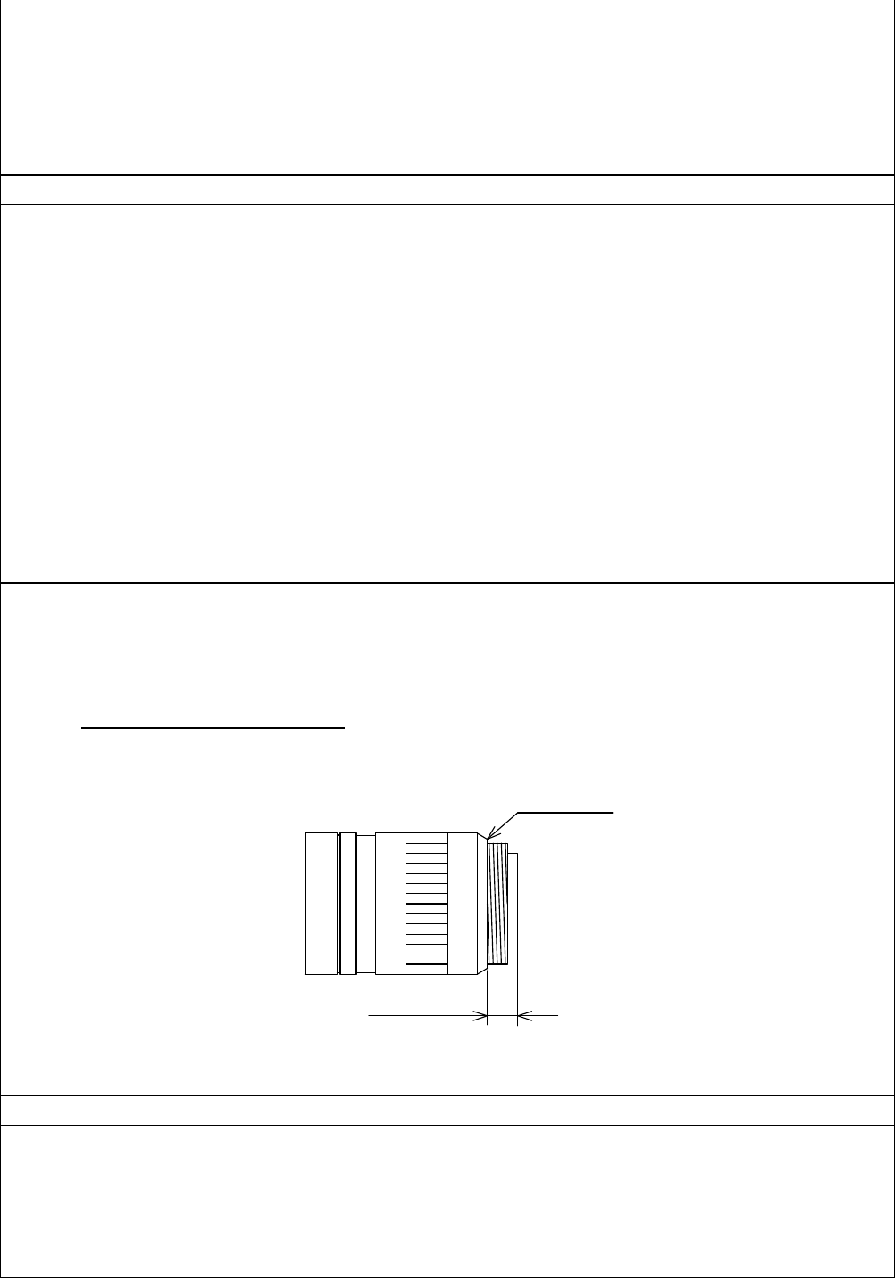
* Combination of C-mount lens
As for the C-mount lens used combining this camera, the projection distance from bottom
of the screw should use 9.9mm or less.
[Ambient condition]
Performance guaranteed
Temperature : From 0 through 40 degree Celsius
Humidity : From 10 through 90 percent (No condensing)
Operation guaranteed
Temperature : From -5 through 45 degree Celsius
Humidity : Less than 90 % (No condensing)
9.9mm or less
C-mount lens
Bottom of
the screw
14
D4134051A
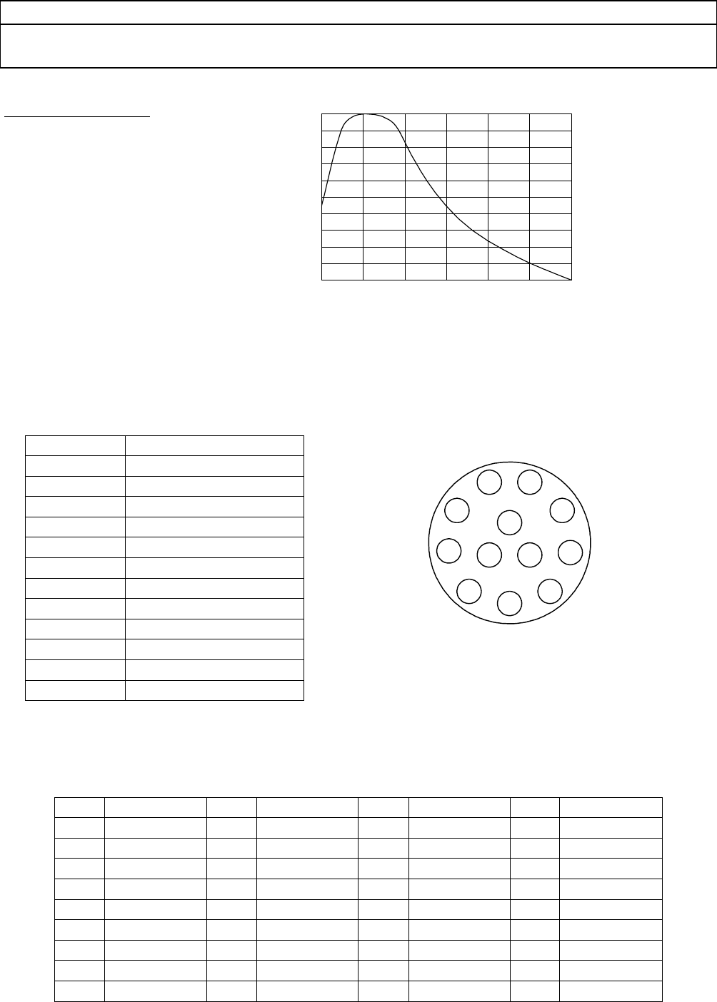
[Spectrum response characteristics (Typical)]
Refer to table SRC below. Graph reflects lens characteristics, but do
not reflect that of light-source.
Table: Typical SRC
X-axis: Wave-length
Y-axis: Relative response
[Connector pin arrangement]
DC IN/SYNC
Connector (Camera side): HR10A-10R-12PB (Manufactured by HIROSE DENKI)
Plug (Cable side): HR10A-10P-12S (Manufactured by HIROSE DENKI)
(2) DATA OUT
Connector (Camera side): DX10A-36S
Connector (Cable side): DX30A-36P, DX-36-CV1 (Cover)
Pin.
Signal name
Pin.
Signal name
Pin.
Signal name
Pin.
Signal name
1 DATA0-H 10 DATA4-L 19 DATA9-H 28 E.HD IN
2 DATA0-L 11 DATA5-H 20 DATA9-L 29 E.VD IN
3 DATA1-H 12 DATA5-L 21 VD OUT-H
30 N.C.
4 DATA1-L 13 DATA6-H 22 VD OUT-L
31 BUSY
5 DATA2-H 14 DATA6-L 23 HD OUT-H
32 WEN
6 DATA2-L 15 DATA7-H 24 HD OUT-L
33 N.C.
7 DATA3-H 16 DATA7-L 25 CLK-H 34 N.C.
8 DATA3-L 17 DATA8-H 26 CLK-L 35 GND
9 DATA4-H 18 DATA8-L 27 TRIG IN 36 GND
DATA0: LSB, DATA9: MSB
Pin number
Signal name
1 GND
2 +12V
3 N.C
4 N.C
5 HD GND
6 E.HD IN
7 E.VD IN
8 GND
9 N.C.
10 WEN
11 TRIG
12 VD GND
1.0
0.9
0.8
0.7
0.6
0.5
0.4
0.3
0.2
0.1
0
Relative Response
Wavelength [nm]
400 500 600 700 800 900 1000
1
11
1
2
22
2
3
33
3
4
44
45
55
56
66
6
7
77
7
8
88
8
9
99
9
10
1010
10
11
1111
11 12
1212
12
Rear-view
15
D4134051A
6. TIMING CHART
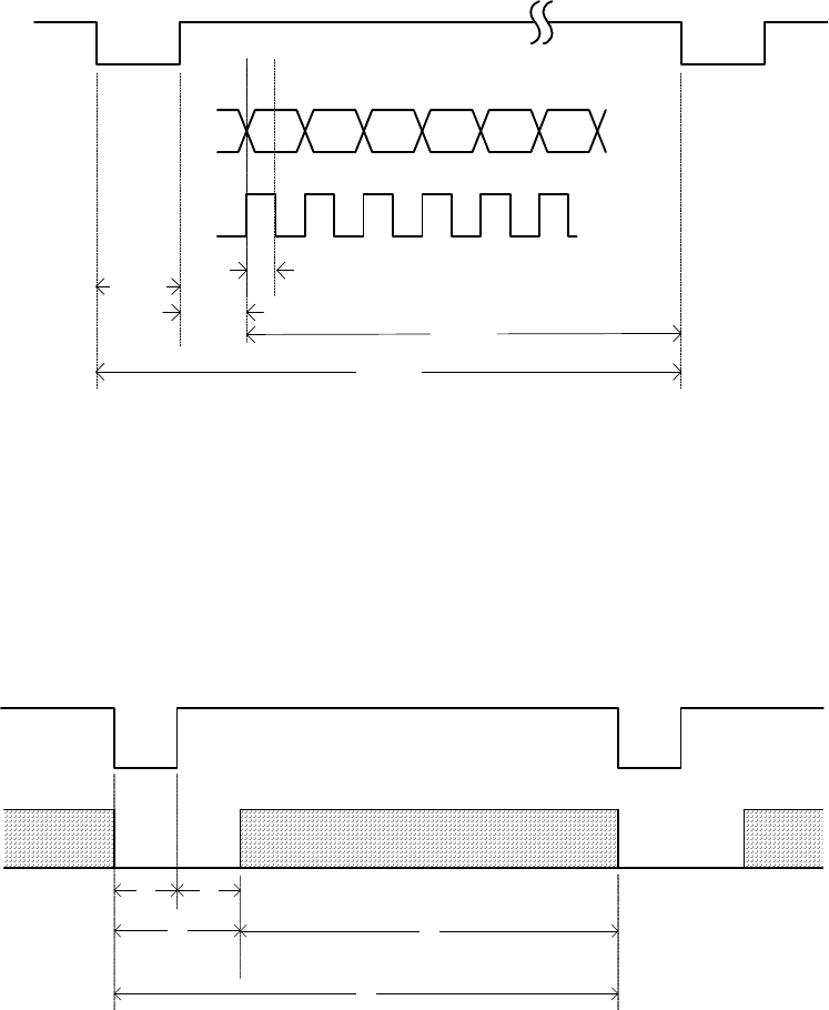
6-1. Digital output
EIA RS644 standard (LVDS)
Driver output voltage Plus/minus 350mV (Differential output) / 100-ohm
H Rate
Total clock counts: 1790CLK / 1H
DATA counts: 1392CLK / 1H
CLK 34.92ns
V rate phase: Same as one in analog timing-chart
V Rate
A=3H
B=3H
C=6H
D=1040H
E=1046H
CLK
DATA
HD
276CLK
1392CLK
1790CLK
17.5ns
122CLK
CD
E
DATA
VD
A B
16
D4134051A
6-2. External sync.
6-3.Read out mode
*15Hz All pixels read out
HD
VD
WEN
SG
VD: 1/15Hz≒65.4ms (1046H) Pulse width:Longer than 1H
E.VD Phase lag
200ns or less against
HD
E.HD
HD
VD
DATA
WEN
CCD
(Exposure)
1046H
(15.29Hz)
Exposure-time
(setting with inner DIP SW)
1 2 3 4 5 6
1038 1039 1040
7DATA
VD
HD
WEN
8
17
D4134051A
*60Hz High-speed draft read out
1 4 9 12 17 20
1028 1033 1036
25DATA
VD
HD
WEN
28 33
HD
VD
DATA
WEN
CCD
(Exposure)
262H
(60.37Hz) Exposure-time
(setting with inner DIP SW)
18
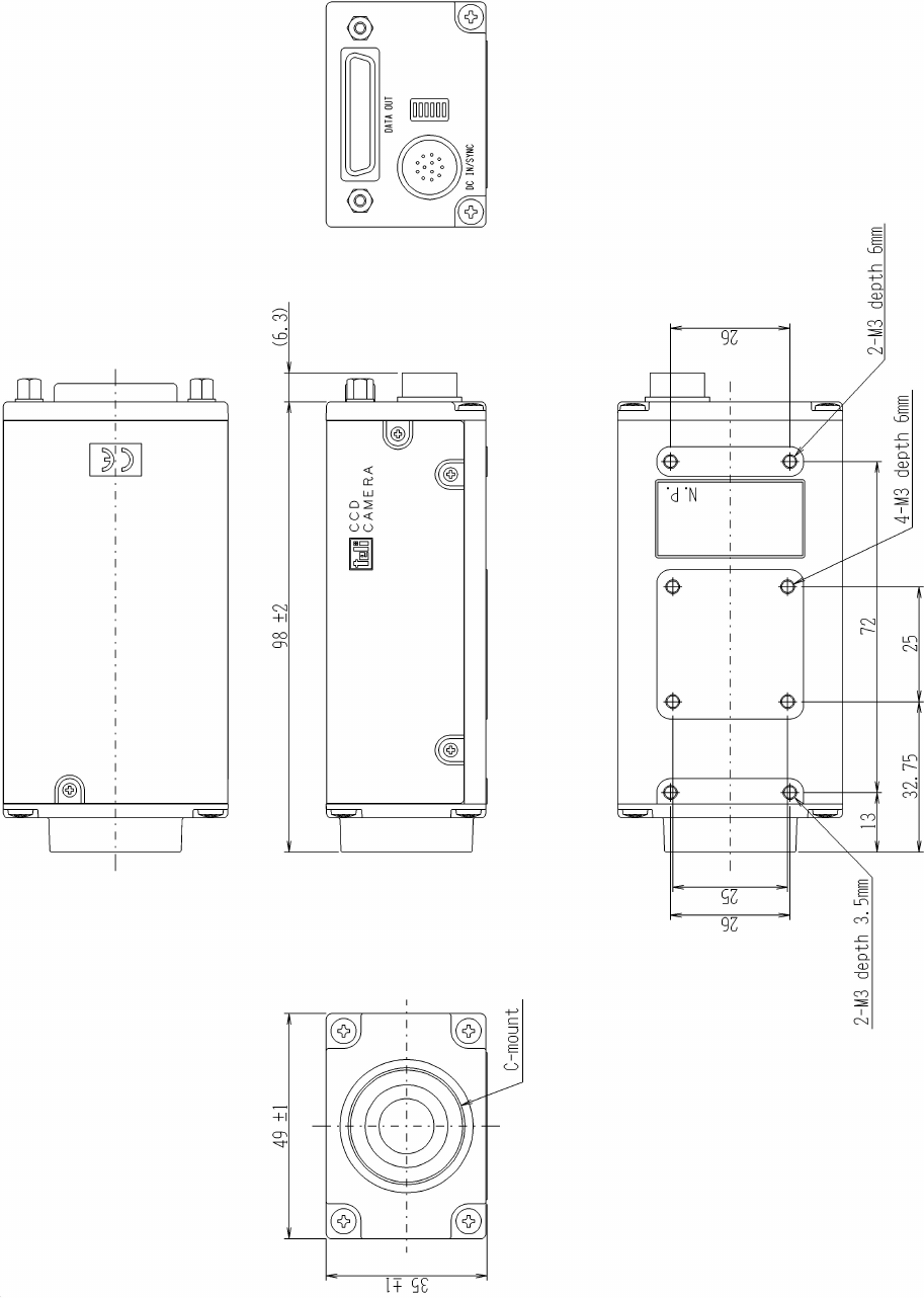
D4134051A
7. EXTERNAL-VIEW DRAWING
