Toshiba Satellite M30 35 Users Manual Personal Computer Maintenance
2014-12-13
: Toshiba Toshiba-Satellite-M30-35-Users-Manual-131010 toshiba-satellite-m30-35-users-manual-131010 toshiba pdf
Open the PDF directly: View PDF ![]() .
.
Page Count: 338 [warning: Documents this large are best viewed by clicking the View PDF Link!]
- SAFETY PRECAUTIONS
- Conventions
- Acronyms
- Keys
- Key operation
- User input
- The display
- Chapter 1Hardware Overview
- Chapter 2Troubleshooting Procedures
- Chapter 3Tests and Diagnostics
- Chapter 4Replacement Procedures
- Appendices
- ch_1toc.pdf
- ch_1.pdf
- ch_2TOC.pdf
- ch_2.pdf
- Troubleshooting
- Troubleshooting Flowchart
- Power Supply Troubleshooting
- System Board Troubleshooting
- FDD Troubleshooting
- HDD Troubleshooting
- Keyboard Troubleshooting
- Display Troubleshooting
- Optical Drive Troubleshooting
- Modem Troubleshooting
- LAN Troubleshooting
- Wireless LAN Troubleshooting
- Sound Troubleshooting
- SD Card Slot Troubleshooting
- ch_3TOC.pdf
- ch_3-1.pdf
- ch_3-2.pdf
- ch_3-3.pdf
- ch_4toc.pdf
- ch_4_1.pdf
- ch_4_2.pdf
- ch_4_3.pdf
- ch_4_4.pdf
- Aptoc.pdf
- ApA.pdf
- ApB.pdf
- ApE.pdf
- ApF.pdf
- ApG.pdf
- ApI.pdf
- ApJ.pdf
Toshiba Personal Computer
Satellite M30-35 Series
Maintenance Manual
TOSHIBA CORPORATION
File Number 960-455

ii Satellite M30-35 Maintenance Manual (960-455)
Copyright
© 2003 by Toshiba Corporation. All rights reserved. Under the copyright laws, this manual
cannot be reproduced in any form without the prior written permission of Toshiba. No patent
liability is assumed with respect to the use of the information contained herein.
Toshiba Personal Computer Satellite M30-35 Series Maintenance Manual
First edition September 2003
Disclaimer
The information presented in this manual has been reviewed and validated for accuracy. The
included set of instructions and descriptions are accurate for the Satellite M30 Series at the
time of this manual's production. However, succeeding computers and manuals are subject
to change without notice. Therefore, Toshiba assumes no liability for damages incurred
directly or indirectly from errors, omissions, or discrepancies between any succeeding
product and this manual.
Trademarks
Intel, Intel SpeedStep and Banias are trade marks or registered trademarks of Intel
Corporation or its subsidiaries in the United States and other countries/regions.
Windows and Microsoft are registered trademarks of Microsoft Corporation.
Photo CD is a trademark owned by its proprietor and used by TOSHIBA under license.
Bluetooth is a trademark owned by its proprietor and used by TOSHIBA under license.
Satellite M30-35 Maintenance Manual (960-455) iii
Preface
This maintenance manual describes how to perform hardware service maintenance for the
Toshiba Personal Computer Satellite M30-35 Series.
The procedures described in this manual are intended to help service technicians isolate
faulty Field Replaceable Units (FRUs) and replace them in the field.
SAFETY PRECAUTIONS
Four types of messages are used in this manual to bring important information to your
attention. Each of these messages will be italicized and identified as shown below.
DANGER: “Danger” indicates the existence of a hazard that could result in death or
serious bodily injury, if the safety instruction is not observed.
WARNING: “Warning” indicates the existence of a hazard that could result in bodily
injury, if the safety instruction is not observed.
CAUTION: “Caution” indicates the existence of a hazard that could result in property
damage, if the safety instruction is not observed.
NOTE: “Note” contains general information that relates to your safe maintenance
service.
Improper repair of the computer may result in safety hazards. Toshiba requires service
technicians and authorized dealers or service providers to ensure the following safety
precautions are adhered to strictly.
Be sure to fasten screws securely with the right screwdriver. If a screw is not fully
fastened, it could come loose, creating a danger of a short circuit, which could cause
overheating, smoke or fire.
If you replace the battery pack or RTC battery, be sure to use only the same model
battery or an equivalent battery recommended by Toshiba. Installation of the wrong
battery can cause the battery to explode.

iv Satellite M30-35 Maintenance Manual (960-455)
The manual is divided into the following parts:
Chapter 1 Hardware Overview describes the Satellite M30 system unit and each
FRU.
Chapter 2 Troubleshooting Procedures explains how to diagnose and resolve
FRU problems.
Chapter 3 Test and Diagnostics describes how to perform test and diagnostic
operations for maintenance service.
Chapter 4 Replacement Procedures describes the removal and replacement of the
FRUs.
Appendices The appendices describe the following:
Handling the LCD module
Board layout
Pin assignments
Keyboard scan/character codes
Key layout
Wiring diagrams
BIOS Rewrite Procedures
Reliability

Satellite M30-35 Maintenance Manual (960-455) v
Conventions
This manual uses the following formats to describe, identify, and highlight terms and
operating procedures.
Acronyms
On the first appearance and whenever necessary for clarification acronyms are enclosed in
parentheses following their definition. For example:
Read Only Memory (ROM)
Keys
Keys are used in the text to describe many operations. The key top symbol as it appears on
the keyboard is printed in boldface type.
Key operation
Some operations require you to simultaneously use two or more keys. We identify such
operations by the key top symbols separated by a plus (+) sign. For example, Ctrl + Pause
(Break) means you must hold down Ctrl and at the same time press Pause (Break). If
three keys are used, hold down the first two and at the same time press the third.
User input
Text that you are instructed to type in is shown in the boldface type below:
DISKCOPY A: B:
The display
Text generated by the computer that appears on its display is presented in the type face
below:
Format complete
System transferred

vi Satellite M30-35 Maintenance Manual (960-455)
Table of Contents
Chapter 1 Hardware Overview
1.1 Features ......................................................................................................................1-1
1.2 System Unit Block Diagram ...................................................................................... 1-7
1.3 3.5-inch Floppy Disk Drive (USB External) ........................................................... 1-14
1.4 2.5-inch Hard Disk Drive......................................................................................... 1-15
1.5 CD-RW/DVD-ROM Drive......................................................................................1-18
1.6 DVD-R/RW Drive ...................................................................................................1-19
1.7 DVD-Multi Drive..................................................................................................... 1-21
1.8 Keyboard.................................................................................................................. 1-23
1.9 TFT Color Display................................................................................................... 1-24
1.10 Power Supply ........................................................................................................... 1-27
1.11 Batteries ................................................................................................................... 1-30
Chapter 2 Troubleshooting Procedures
2.1 Troubleshooting ......................................................................................................... 2-1
2.2 Troubleshooting Flowchart........................................................................................ 2-2
2.3 Power Supply Troubleshooting.................................................................................. 2-6
2.4 System Board Troubleshooting................................................................................ 2-17
2.5 FDD Troubleshooting .............................................................................................. 2-30
2.6 HDD Troubleshooting ............................................................................................. 2-33
2.7 Keyboard Troubleshooting ...................................................................................... 2-38
2.8 Display Troubleshooting.......................................................................................... 2-40
2.9 Optical Drive Troubleshooting ................................................................................ 2-43
2.10 Modem Troubleshooting.......................................................................................... 2-45
2.11 LAN Troubleshooting.............................................................................................. 2-47
2.12 Wireless LAN Troubleshooting............................................................................... 2-48
2.13 Sound Troubleshooting............................................................................................ 2-52
2.14 SD Card Slot Troubleshooting................................................................................. 2-55

Satellite M30-35 Maintenance Manual (960-455) vii
Chapter 3 Tests and Diagnostics
3.1 The Diagnostic Test ................................................................................................... 3-1
3.2 Executing the Diagnostic Test ................................................................................... 3-3
3.3 Subtest Names............................................................................................................ 3-7
3.4 System Test................................................................................................................ 3-9
3.5 Memory Test............................................................................................................ 3-12
3.6 Keyboard Test.......................................................................................................... 3-13
3.7 Display Test ............................................................................................................. 3-16
3.8 Floppy Disk Test...................................................................................................... 3-19
3.9 Printer Test............................................................................................................... 3-21
3.10 Async Test ............................................................................................................... 3-23
3.11 Hard Disk Test ......................................................................................................... 3-24
3.12 Real Timer Test........................................................................................................ 3-27
3.13 NDP Test.................................................................................................................. 3-29
3.14 Expansion Test......................................................................................................... 3-30
3.15 CD-ROM/DVD-ROM Test ..................................................................................... 3-31
3.16 LAN Test ................................................................................................................. 3-32
3.17 Error Code and Error Status Names......................................................................... 3-33
3.18 Hard Disk Test Detail Status ................................................................................... 3-36
3.19 Head Cleaning.......................................................................................................... 3-38
3.20 Log Utilities ............................................................................................................. 3-39
3.21 Running Test............................................................................................................ 3-41
3.22 Floppy Disk Drive Utilities...................................................................................... 3-42
3.23 System Configuration .............................................................................................. 3-47
3.24 Wireless LAN Test Program (Calexico).................................................................. 3-49
3.25 Wireless LAN Test Program (Ahteros 11b/g or 11a/b/g)........................................ 3-50
3.26 Sound/LAN/Modem Test Program.......................................................................... 3-53
3.27 IEEE1394 Test Program .......................................................................................... 3-57

viii Satellite M30-35 Maintenance Manual (960-455)
Chapter 4 Replacement Procedures
4.1 General....................................................................................................................... 4-1
4.2 Battery Pack ............................................................................................................... 4-9
4.3 PC Card.................................................................................................................... 4-11
4.4 SD Card.................................................................................................................... 4-13
4.5 HDD......................................................................................................................... 4-14
4.6 Optical Drive............................................................................................................ 4-17
4.7 Memory Module/Modem Daughter Card ................................................................ 4-20
4.8 Wireless LAN Card.................................................................................................. 4-24
4.9 Keyboard.................................................................................................................. 4-26
4.10 Switch Cover ASSY/Switch Membrane.................................................................. 4-29
4.11 Display Assembly .................................................................................................... 4-32
4.12 Touch Pad Button .................................................................................................... 4-36
4.13 Microphone .............................................................................................................. 4-37
4.14 Touch Pad ................................................................................................................ 4-39
4.15 RTC Battery ............................................................................................................. 4-41
4.16 Sound Board/Touch Pad Holder .............................................................................. 4-43
4.17 CD-Key ASSY......................................................................................................... 4-46
4.18 System Board ........................................................................................................... 4-47
4.19 CPU.......................................................................................................................... 4-50
4.20 Speaker..................................................................................................................... 4-53
4.21 Fan............................................................................................................................ 4-55
4.22 USB Board/DC-IN Jack/Network Jack ................................................................... 4-56
4.23 Power Board/RGB Board ........................................................................................ 4-58
4.24 Display Mask ........................................................................................................... 4-61
4.25 FL Inverter ............................................................................................................... 4-63
4.26 LCD Module ............................................................................................................ 4-65
4.27 Sensor/Switch Board................................................................................................ 4-69
4.28 LCD Cable Wireless LAN Antenna ........................................................................ 4-70
4.29 Fluorescent Lamp..................................................................................................... 4-76

Satellite M30-35 Maintenance Manual (960-455) ix
Appendices
Appendix A Handling the LCD Module ........................................................................... A-1
Appendix B Board Layout ................................................................................................ B-1
Appendix C Pin Assignments............................................................................................ C-1
Appendix D Character Codes ............................................................................................ D-1
Appendix E Key Layout.....................................................................................................E-1
Appendix F Reliability.......................................................................................................F-1
Appendix G BIOS Rewrite Procedures ............................................................................. G-1
Appendix H EC/KBC Rewrite Procedures........................................................................ H-1
Appendix I Reliability........................................................................................................I-1
Appendix J SETUP ............................................................................................................J-1

x Satellite M30-35 Maintenance Manual (960-455)

Chapter 1
Hardware Overview

1 Hardware Overview
1-ii Satellite M30-35 Maintenance Manual (960-455)

1 Hardware Overview
Chapter 1 Contents
1.1 Features.......................................................................................................................1-1
1.2 System Unit Block Diagram.......................................................................................1-7
1.3 3.5-inch Floppy Disk Drive (USB External)............................................................1-14
1.4 2.5-inch Hard Disk Drive .........................................................................................1-15
1.5 CD-RW/DVD-ROM Drive.......................................................................................1-18
1.6 DVD-R/RW Drive....................................................................................................1-19
1.7 DVD-Multi Drive ....................................................................................................1-21
1.8 Keyboard ..................................................................................................................1-23
1.9 TFT Color Display ...................................................................................................1-24
1.9.1 LCD Module .......................................................................................1-24
1.9.2 FL Inverter Board ...............................................................................1-26
1.10 Power Supply............................................................................................................1-27
1.11 Batteries....................................................................................................................1-30
1.11.1 Main Battery .......................................................................................1-30
1.11.2 Battery Charging Control....................................................................1-31
1.11.3 RTC battery.........................................................................................1-32
Satellite M30-35 Maintenance Manual (960-455) 1-iii

1 Hardware Overview
1-iv Satellite M30-35 Maintenance Manual (960-455)
Figures
Figure 1-1 Front of the computer .....................................................................................1-6
Figure 1-2 System unit configuration...............................................................................1-6
Figure 1-3 System unit block diagram .............................................................................1-7
Figure 1-4 3.5-inch FDD (USB External)......................................................................1-14
Figure 1-5 2.5-inch HDD ...............................................................................................1-15
Figure 1-6 CD-RW/DVD-ROM drive ..........................................................................1-18
Figure 1-7 DVD-R/RW drive.........................................................................................1-19
Figure 1-8 DVD-Multi drive ..........................................................................................1-21
Figure 1-9 Keyboard ......................................................................................................1-23
Figure 1-10 LCD module .................................................................................................1-24
Tables
Table 1-1 3.5-inch FDD specifications.........................................................................1-14
Table 1-2 2.5-inch HDD specifications ........................................................................1-15
Table 1-3 CD-RW/DVD-ROM drive specifications ....................................................1-18
Table 1-4 DVD-R/RW drive specifications..................................................................1-20
Table 1-5 DVD Multi drive specifications ...................................................................1-21
Table 1-6 LCD module specifications ..........................................................................1-24
Table 1-7 FL inverter board specifications...................................................................1-26
Table 1-8 Power supply output rating...........................................................................1-28
Table 1-9 Battery specifications ...................................................................................1-30
Table 1-10 Time required for quick charges...................................................................1-31
Table 1-11 RTC battery charging/data preservation time...............................................1-32

1.1 Features 1 Hardware Overview
1 Features
1.1 Features
The Toshiba Satellite M30 Personal Computer uses extensive Large Scale Integration (LSI),
and Complementary Metal-Oxide Semiconductor (CMOS) technology extensively to provide
compact size, minimum weight, low power usage and high reliability. This computer
incorporates the following features and benefits: The product configuration is BTO-
compatible so that a system can be designed to suit a specific purpose.
Microprocessor
The Satellite M30 computer is equipped with an Intel Banias Processor, which
incorporates a math co-processor, a 64KB L1 cache memory and a 1MB L2 cache
memory. The processor runs with one of the following speeds:
Intel Banias Processor 1.40GHz (1.35V) / 1.20GHz (0.85V) •
•
•
•
Intel Banias Processor 1.50GHz (1.35V) / 1.20GHz (0.85V)
Intel Banias Processor 1.60GHz (1.35V) / 1.20GHz (0.85V)
Intel Banias Processor 1.70GHz (1.35V) / 1.20GHz (0.85V)
This processor operates at 1.35V-0.8V and 100MHz bus clock
Chipset
The Satellite M30 is equipped with Intel Odem+, Intel ICH4-M and YEBISU-SS.
Cache Memory
64KB primary cache (in CPU) and 1MB secondary cache (in CPU)
GPU Controller
The computer has a nVIDIA NV34M controller. The internal VRAM is 32MB/64M,
DDR200MHz.
Memory
Two DDR SO-DIMM slots are available for installation of PC2700 compatible 256,
512MB and 1GB memory modules. The memory is expandable up to 2GB.
Built-in HDD
The computer has a 40GB, 60GB or 80GB internal drive. 2.5 inch x 9.5mm height.
USB FDD
An external two-mode 3.5-inch FDD, which connects with a USB port, supports 720KB
and 1.44MB formats and enables booting from system FD.
Satellite M30-35 Maintenance Manual (960-455) 1-1

1 Hardware Overview 1.1 Features
CD-RW/DVD Drive
This drive is a combination of DVD-ROM and CD-R/RW Drive. . It is full-size and runs
either 12cm (4.72-inch) or 8cm (3.15-inch) DVD/CDs without an adaptor. This drive
reads CD-ROM at maximum 24-speed, reads DVD-ROM at maximum 8-speed writes
CD-R at maximum 24-speed, and writes CD-RW at maximum 24-speed.
DVD-R/RW Drive
A full-size DVD-R/-RW drive module lets you record data to rewritable CD/DVDs as
well as run either 12 cm (4.72") or 8 cm (3.15") CD/DVDs without using an adaptor. It
reads DVD-ROMs at maximum 8 speed, CD-ROMs at maximum 24 speed and CD-Rs at
maximum 16 speed. It writes CD-R at up to 16 speed, CD-RW at up to 10 speed, DVD-R
and DVD-RW at single speed.
DVD Multi Drive
This drive is a combination of CD-R/RW, DVD-R/RW and DVD-RAM Drive. It is full-
size and runs either 12cm (4.72-inch) or 8cm (3.15-inch) DVD/CDs without an adaptor.
This drive reads CD-ROM at maximum 24-speed, reads DVD-ROM at maximum 8-speed
writes CD-R at maximum 16-speed, writes CD-RW at maximum 8-speed, writes DVD-R
at maximum 2-speed, writes DVD-RW at maximum 1-speed,.and writes DVD-RAM at
maximum 2-speed.
Display
The display comes in the following three types:
15.4” WXGA-TFT color display, resolution 1280(H)×800(V), 16M colors •
A high-resolution external monitor connected to the computer can display up to
2048(H)×1536(V), at 16M colors.
Keyboard
An-easy-to-use 85(US)/86(UK)-key keyboard provides a numeric keypad overlay for fast
numeric data entry or for cursor and page control. The keyboard also includes two keys
that have special functions in Microsoft Windows 2000/X P. It supports software that
uses a 101- or 102-key enhanced keyboard.
Touch pad
Touch pad is installed as a pointing device.
Batteries
The computer has two batteries: a rechargeable Lithium-Ion main battery pack and RTC
battery (that backs up the Real Time Clock and CMOS memory).
1-2 Satellite M30-35 Maintenance Manual (960-455)

1.1 Features 1 Hardware Overview
Universal Serial Bus (USB2.0)
Three USB ports are provided. The ports comply with the USB2.0 standard, which
enables data transfer speeds 40 times faster than USB1.1 standard. USB1.1 is also
supported.
IEEE 1394 port
The computer comes with one IEEE 1394 port. It enables high-speed data transfer directly
from external devices such as digital video cameras.
Parallel port
The parallel port enables connection of parallel printer or other parallel devices. (ECP
compatible)
External monitor port
The port enables connection of an external monitor, which is recognized automatically by
Video Electronics Standards Association (VESA) Display Data Channel (DDC) 2B
compatible functions.
PC card slot
The PC card slot (PCMCIA) accommodates one 5mm Type II card. The slot support 16-
bit PC cards and Card Bus PC cards. CardBus supports 32-bit PC cards.
SD Card
An SD Card Slot can accommodate Secure Digital flash memory cards with various
capacities. SD cards let you easily transfer data from devices, such as digital cameras and
Personal Digital Assistants, that use SD Card flash-memory.
Infrared port
The infrared port is compatible with Fast InfraRed (FIR) standards enabling cableless 4
Mbps, 1.152 Mbps, 115.2 kbps, 57.6 kbps, 38.4 kbps, 19.2 kbps or 9.6 kbps data transfer
with Infrared Data Association (IrDA) 1.1 compatible external devices.
Satellite M30-35 Maintenance Manual (960-455) 1-3

1 Hardware Overview 1.1 Features
Sound system
The sound system is equipped with the following features:
AC 97 Link •
•
•
•
•
•
•
Sound CODEC: STAC9750
Stereo speakers
Built-in Microphone (Mono)
Volume control knob
Stereo Headphone jack
External microphone jack
Video-out jack
The video jack enables to transfer NTSC or PAL data to external devices connected with
S-Video cable.
Internal modem
The internal modem is equipped as a modem daughter card (MDC).
The internal modem provides capability for data and fax communication and supports
V.90/92. For data reception it operates at 56,000bps and for data transmission it operates
at 33,600bps. For fax transmission it operates at 14,400bps. It is also equipped with
Speakerphone and TAM (Telephony Answering Machine) function. The speed of data
transfer and fax depends on analog telephone line conditions. It has an RJ11 modem jack
for connecting to a telephone line. Both of V.90 and V.92 is supported in USA and
Canada. In other regions, only V.90 is available.
Internal LAN
The computer is equipped with LAN circuits that support Ethernet LAN (10 megabits per
second, 10BASE-T), Fast Ethernet LAN (100 megabits per second, 100 BASE-Tx). It also
supports Wakeup on LAN (WOL) and Magic Packet.
Mini PCI Card slot (1 slot)
Some computers in this series are equipped with a wireless LAN mini-PCI card that is
compatible with other LAN systems based on Direct Sequence Spread
Spectrum/Orthogonal Frequency Division Multiplexing radio technology that complies
with the IEEE802.11 Standard (Revision A, B or G) and Turbo Mode. Revisions A and G
support a data transfer rate up to 54 Mbit/s. Revision-B supports a data transfer rate up to
11 Mbit/s. Turbo Mode supports a data transfer rate up to 108 Mbit/s.
1-4 Satellite M30-35 Maintenance Manual (960-455)

1.1 Features 1 Hardware Overview
Internet button
This button launches an Internet browser. If the computer’s power is off, you can press
this button to turn on the computer’s power and launch the browser automatically in one
step.
TOSHIBA Console button
This button launches an application automatically. The default is TOSHIBA Console.
S-Video out button
Pressing this button sets the display device to TV (Video out). Pressing it again returns to
LCD.
Satellite M30-35 Maintenance Manual (960-455) 1-5
1 Hardware Overview 1.1 Features
The front of the computer is shown in figure 1-1 and the system unit configuration is shown
in figure 1-2.
Figure 1-1 Front of the computer
Figure 1-2 System unit configuration
1-6 Satellite M30-35 Maintenance Manual (960-455)
1.2 System Unit Block Diagram 1 Hardware Overview
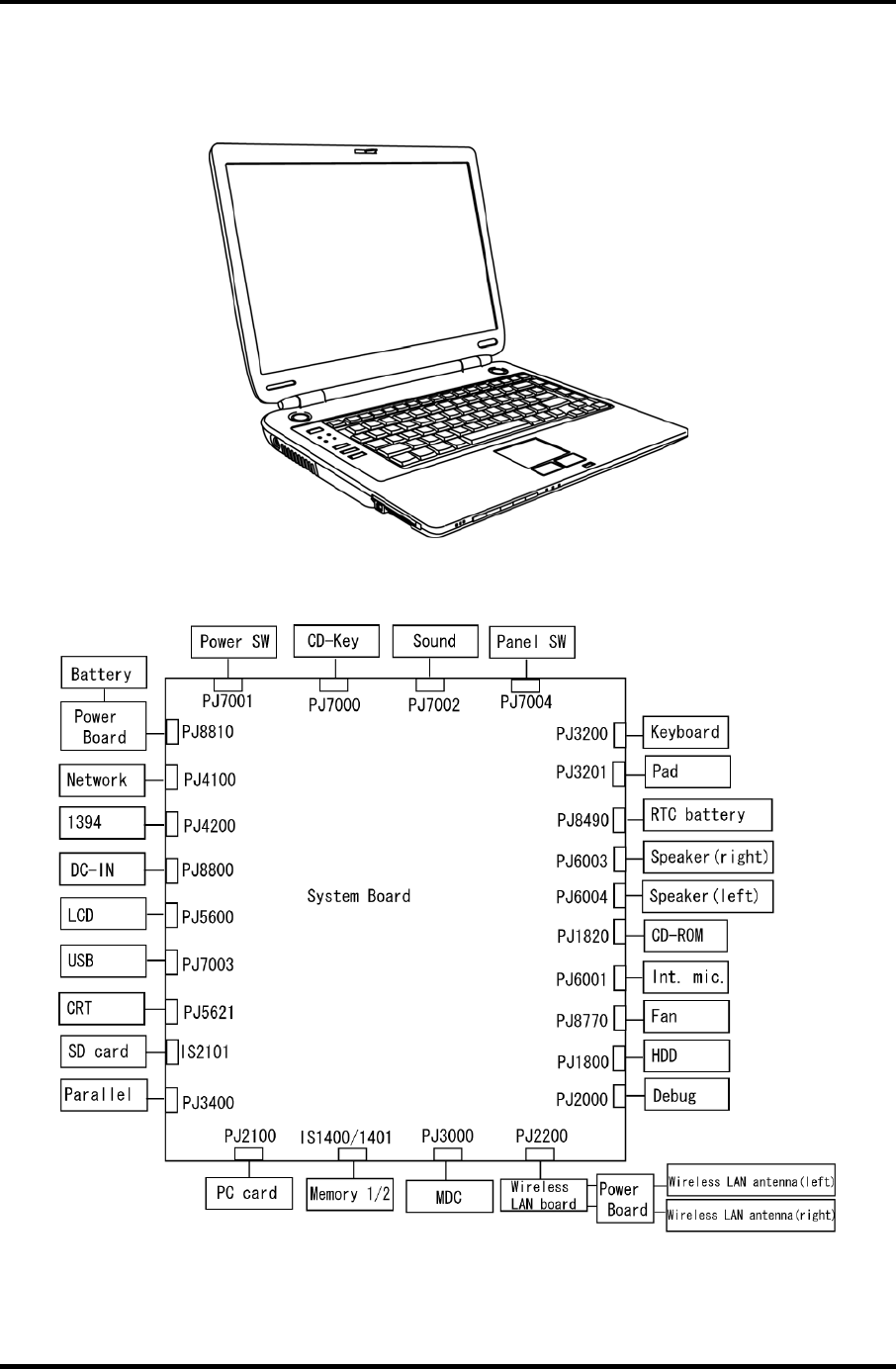
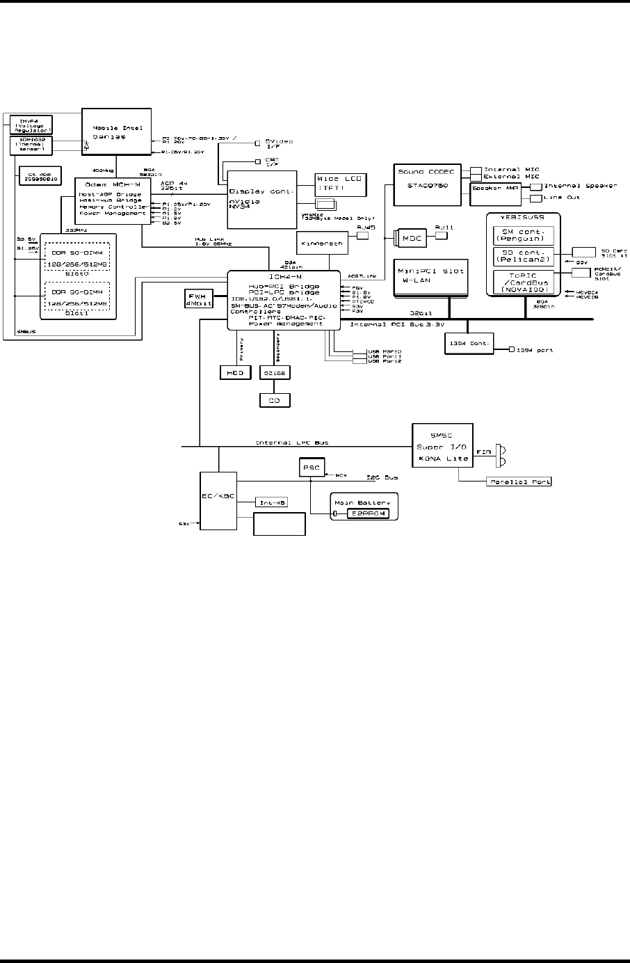
1.2 System Unit Block Diagram
Figure 1-3 is a block diagram of the system unit.
Internal
Touch Pad
Figure 1-3 System unit block diagram
Satellite M30-35 Maintenance Manual (960-455) 1-7

1 Hardware Overview 1.2 System Unit Block Diagram
The system unit is composed of the following major components:
Processor
Intel Banias Processor 1.40GHz •
•
•
•
– Processor core speed: 1.40GHz (Performance Mode at 1.35V) and 1.20GHz
(Battery Optimized Mode at 0.85V)
– Processor bus speed: 400MHz
– Integrated L1 cache memory: 32KB instruction cache and 32KB write-back
data cache, 4-way set associative
– Integrated L2 cache memory: 1MB ECC protected cache data array, 8-way set
associative
– Integrated NDP
Intel Banias Processor 1.50GHz
– Processor core speed: 1.50GHz (Performance Mode at 1.35V) and 1.20GHz
(Battery Optimized Mode at 0.85V)
– Processor bus speed: 400MHz
– Integrated L1 cache memory: 32KB instruction cache and 32KB write-back
data cache, 4-way set associative
– Integrated L2 cache memory: 1MB ECC protected cache data array, 8-way set
associative
– Integrated NDP
Intel Banias Processor 1.60GHz
– Processor core speed: 1.60GHz (Performance Mode at 1.35V) and 1.20GHz
(Battery Optimized Mode at 0.85V)
– Processor bus speed: 400MHz
– Integrated L1 cache memory: 32KB instruction cache and 32KB write-back
data cache, 4-way set associative
– Integrated L2 cache memory: 1MB ECC protected cache data array, 8-way set
associative
– Integrated NDP
Intel Banias Processor 1.70GHz
– Processor core speed: 1.70GHz (Performance Mode at 1.35V) and 1.20GHz
(Battery Optimized Mode at 0.85V)
– Processor bus speed: 400MHz
– Integrated L1 cache memory: 32KB instruction cache and 32KB write-back
data cache, 4-way set associative
– Integrated L2 cache memory: 1MB ECC protected cache data array, 8-way set
associative
– Integrated NDP
1-8 Satellite M30-35 Maintenance Manual (960-455)

1.2 System Unit Block Diagram 1 Hardware Overview
Memory
Two memory slots are provided. Expansion up to 2GB (2,048MB) is available.
Supports DDR CL2/2.5 •
•
•
•
•
•
•
•
Supports PC2700
– 256MB: 256Mbit (16M × 16bit) chips × 8
– 512MB: 512Mbit (32M × 8bit) chips × 16
– 512Mbit (32M × 16bit) chips × 8
– 1GB: 512Mbit (64M × 8 bit) chips × 16
200 pin, SO Dual In-line Memory Modules (SO-DIMM)
2.5 volt operation
Intel Odem+ (North Bridge)
One Intel RG82P4300M is used.
Features:
– Banias Processor System Bus Support
– DRAM Controller supporting DDR333/DDR266/DDR200, 1GB max
– Accelerated Graphics Port Interface: adheres to AGP2.0, AGP×4 mode
– Hub Link Interface
– 593-ball 37.5×37.5 mm FC-BGA package
Intel ICH4-M (South Bridge)
One Intel 82801LAM is used.
This gate array has the following features:
– Hub Link Interface
– PCI Rev2.2 Interface (6 PCI REQ/GNT Pairs)
– BusMaster IDE Controller (Ultra ATA 100/66/33)
– USB 1.1/2.0 Controller 6 Prots (EHCI: Enhanced Host Controller)
– I/O APIC (ACPI 1.06)
– SMBus2.0 Controller
– FWH Interface (BIOS)
– LPC Interface (EC/KBC, Super I/O)
– IRQ Controller
– Serial Interrupt Controller
– Power Management Controller
– Deeper Sleep (C4) Support
– Suspend/Resume Control
– AC'97 2.2 Interface
– Internal RTC
– Internal LAN Controller (WfM2.0)
– 421-ball 31×31mm BGA Package
Satellite M30-35 Maintenance Manual (960-455) 1-9

1 Hardware Overview 1.2 System Unit Block Diagram
PC Card Controller Gate Array
One YEBISU-SS gate array is used. •
•
•
•
This gate array has the following functions and components.
– PCI interface (PCI Revision2.2)
– CardBus/PC Card controller (Yenta2 Version2.2)
– SD memory card controller (SDHC Ver.1.2)
– SD IO card controller (Ver.1.0)
– SmartMedia controller (SMHC Ver.01/SMIL1.0)
– SIO (UART) controller (MS Debug Port Specification Ver.1.0)
– Docking station interface
– Q switch control, reset control
– External device interface
Firmware Hub (FWH)
One Intel 82802AB8 is used.
This gate array has the following features:
– Intel platform compatibility
– Firmware hub hardware interface mode
– Industry-standard packages
– Two configurable interfaces
– 4Mbits of flash memory for platform code/data nonvolatile storage
– Address/Address-Multiplexed (A/A Mux) interface/mode
– Case temperature operating range
– Vcc: 3.3V ± 0.3V
– Vpp: 3.3V and 12V for fast programming (80 hours maximum)
– 4Mbits of flash memory are used as shown below:
– 64KB are used for VGA-BIOS.
– 192KB are used for system BIOS.
– 8KB are used for plug and play data area.
– 8KB are used for password security.
– 16KB are used for boot strap.
– 64KB are used for ACPI P code.
– 64KB are used for LOGO.
– 64KB are reserved for LAN BIOS.
– 32KB are reserved.
1-10 Satellite M30-35 Maintenance Manual (960-455)

1.2 System Unit Block Diagram 1 Hardware Overview
GPU Controller
One nVIDIA NV34M chip is used. The GPU controller incorporates graphics accelerator,
video accelerator.
– VRAM 32MB (4M × 32 × 2)/64MB (4M × 32 × 4) DDR200MHz
– AGP bus R2.0 x 4
– LCD Interface LVDS 2ch
– TV Encoder: S-Video 4pin connectorTvxpress2
Sound Controller
AC-Link (in the South Bridge) and STAC975051T (Sigmatel made) are used.
Amplifier, Internal microphone, internal stereo speakers, stereo headphone
connector, external microphone connector and volume control knob are mounted.
•
•
•
EC/KBC (Embedded Controller/Keyboard Controller)
One Mitsubishi M306K9FCLRP micon chip functions as both EC and KBC.
EC
This controller controls the following functions:
– Power supply sequence
– Thermal conditions
– LEDs
– Beep
– Device ON/OFF
– Fan speed
– Universal I/O port
– Docker Docking Sequence
– Battery capacity check
– Forced reset
– Flash rewriting
– EC interface
– I2C communication
– EC access
– Slim Select Bay Control
KBC
This controller has the following functions:
– Scan controller to check status of keyboard matrix
– Interface controller between the keyboard scan controller and the system
– Control of switching and simultaneous operation of the accupoint/external
PS/2 mouse and of the internal keyboard/external PS/2 keyboard
PSC (Power Supply Controller)
Satellite M30-35 Maintenance Manual (960-455) 1-11

1 Hardware Overview 1.2 System Unit Block Diagram
One TMP87PM48U chip is used. •
•
•
•
•
•
•
•
•
This controller controls the power sources.
Clock Generator
One ICS950812CGT is used.
This device generates the system clock.
Modem Controller
One built-in Askey-made 1456VQL4A(INT) modem card
This controller has the following functions:
– Digital line protection support
– Ring wake up support
– AC97 interface
– Supports V.92 56k Modem/Fax.
Internal LAN Controller
One Kinnereth-R (82562EP) chip is used.
– Supports 10/100Mbit Ethernet.
– Supports LED and WOL.
Wireless LAN
– Mini-PCI Type III 1slot
– Supports Kill SW.
– Supports Wireless LAN through PCMCIA
– 802.11b, 802.11a/b: Intel-made
– 802.11b/g, 802.11a/b/g: Atheros-made
Super I/O
One LPC 47N227 chip is used.
– This gate array has the following features:
– Floppy Disk Controller
– Serial Port Controller
– Infrared Communications Controller
– Parallel Port Controller
IEEE1394
One TSB43AB22 is used.
1-12 Satellite M30-35 Maintenance Manual (960-455)

1.2 System Unit Block Diagram 1 Hardware Overview
Sensor
Thermal Sensor: One ADM1032AR chip is used. •
• LCD Sensor: One NRS-701-1015T is used.
Satellite M30-35 Maintenance Manual (960-455) 1-13
1 Hardware Overview 1.3 3.5-inch Floppy Disk Drive (USB External)
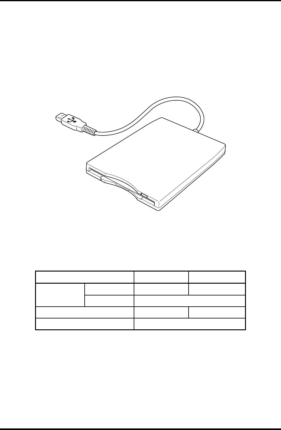
1.3 3.5-inch Floppy Disk Drive (USB External)
The 3.5-inch USB FDD is a thin, high-performance reliable drive that supports 720KB and
1.44MB.
The FDD is shown in figure 1-4. The specifications for the FDD are listed in Table 1-1.
Figure 1-4 3.5-inch FDD (USB External)
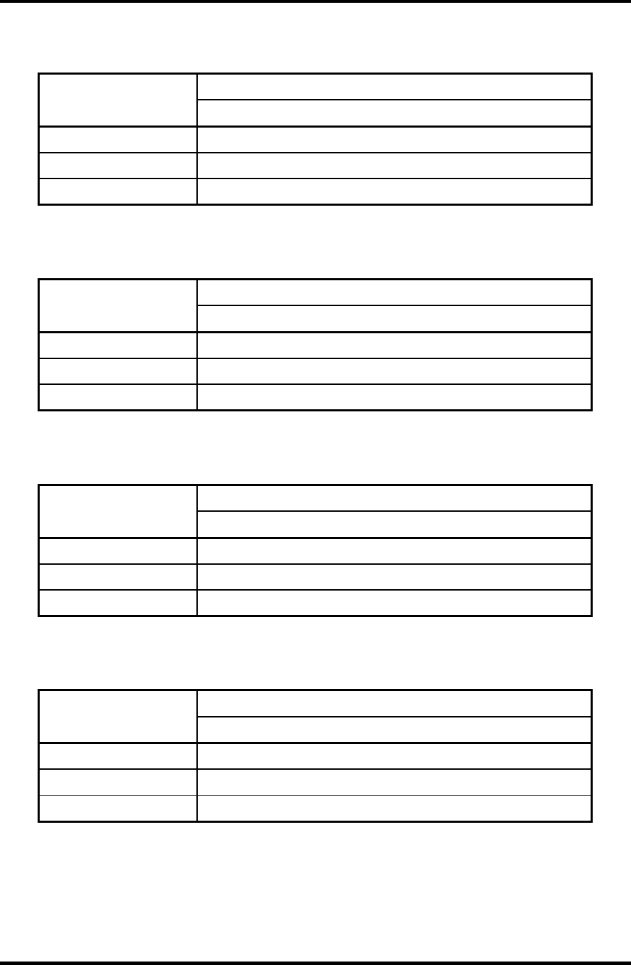
Table 1-1 3.5-inch FDD specifications
Items 720KB mode 1.44MB mode
FDD part
250K bits/second
500K bits/second Data transfer
rate USB Full speed mode (12M bits/second)
Disk rotation speed 300rpm 360rpm
Track density 5.3 track/mm (135TPI)
1-14 Satellite M30-35 Maintenance Manual (960-455)
1.4 2.5-inch Hard Disk Drive 1 Hardware Overview
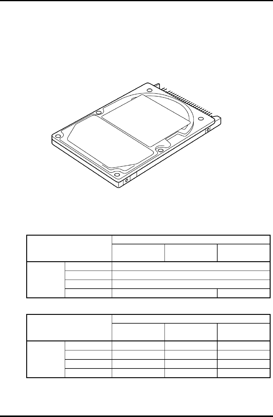
1.4 2.5-inch Hard Disk Drive
The removable HDD is a random access non-volatile storage device. It has a non-removable
2.5-inch magnetic disk and mini-Winchester type magnetic heads.
The computer supports a 40GB, 60GB and 80GB HDD.
The HDD is shown in figure 1-5. Specifications are listed in Table 1-2.
Figure 1-5 2.5-inch HDD
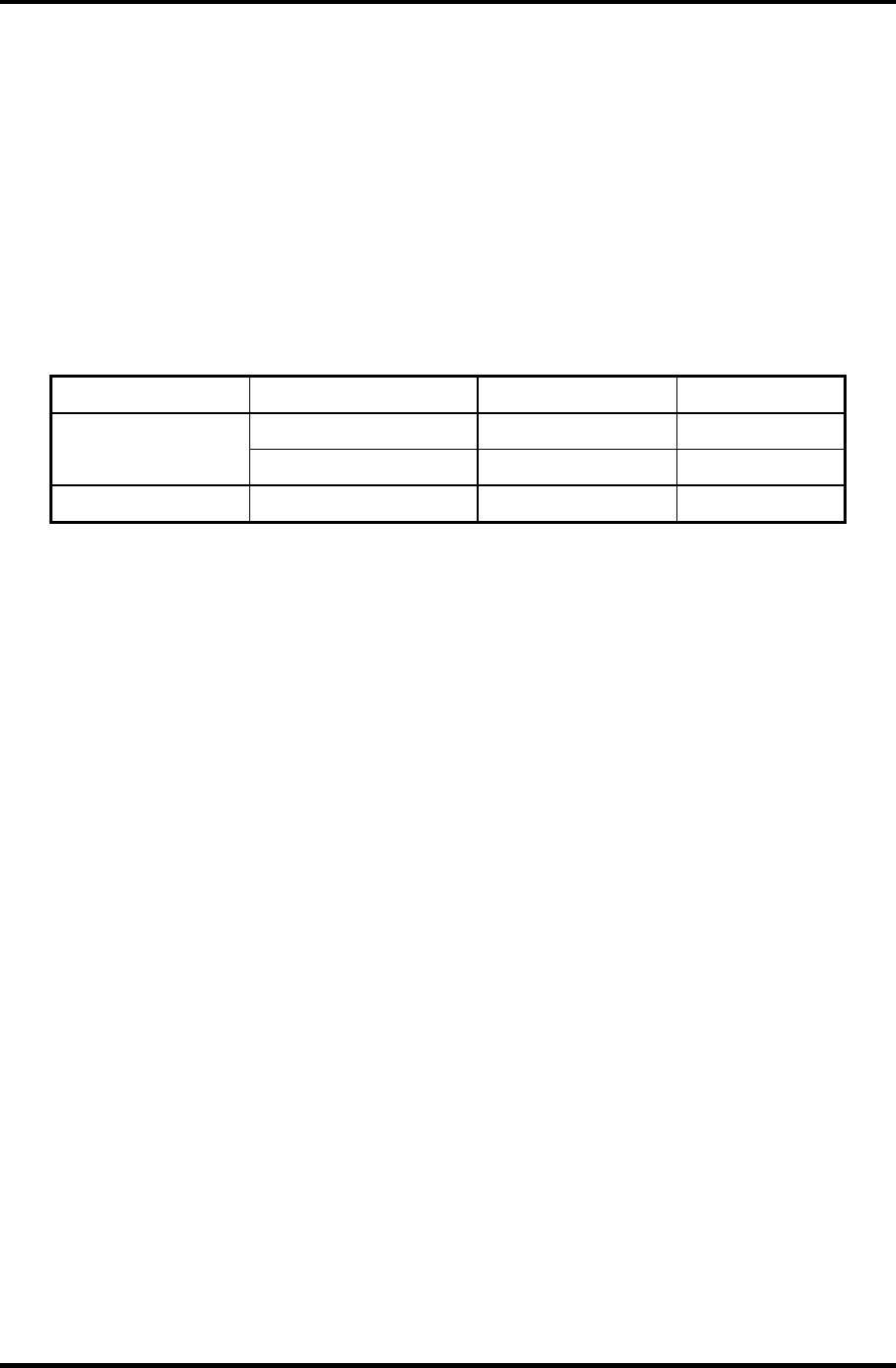
Table 1-2 2.5-inch HDD specifications (1/2)
Parameter Specifications
TOSHIBA
HDD2182B
TOSHIBA
HDD2183
TOSHIBA
HDD2184B
Outline Width (mm) 69.85
dimensions Height (mm) 9.5
Depth (mm) 100
Weight (g) 99 max. 102 max.
Parameter Specifications
HITACHI
G8C0000Z410
HITACHI
G8C0000Z610
HITACHI
G8BC00013610
Outline Width (mm) 69.85±0.25 69.85±0.25 70 max
dimensions Height (mm) 9.5±0.25 9.5±0.25 9.5±0.25
Depth (mm)
100±0.25 100±0.25 100±0.45
Weight (g)
95 max. 99 max. 95 max.
Satellite M30-35 Maintenance Manual (960-455) 1-15
1 Hardware Overview 1.4 2.5-inch Hard Disk Drive
Parameter Specifications
HITACHI
GBC000Z810
HITACHI
GBC000014810
TOSHIBA
HDD2188B
Outline Width (mm) 69.85±0.25 69.85±0.25 69.85
dimensions Height (mm) 9.5±0.25 9.5±0.25 9.5
Depth (mm)
100±0.25 100.2±0.25 100
Weight (g)
99 max 102 99 max.
Table 1-2 2.5-inch HDD specifications(2/2)
Specifications
Parameter TOSHIBA
HDD2182B
TOSHIBA
HDD2183
TOSHIBA
HDD2184
Storage size (formatted) 40GB 60GB 60GB
Speed (RPM) 4200 5400
Data transfer speed
(Mb/sec) 154.3-298.0 202.9-373.3
Interface transfer rate
(MB/s)
100 max.
(Ultra DMA mode)
Track density (Ktpi) 78.9
Access Time
Average seek (sec) 12
Start time (sec) 4 typ. 4 typ.
10 max.
Specifications
Parameter HITACHI
G8C000Z410
HITACHI
G8C0000Z610
HITACHI
G8BC00013610
Storage size (formatted) 40GB 60GB
Speed (RPM) 4200 5400
Data transfer speed
(Mb/sec) 350 typ. 263.2-401.6
Interface transfer rate
(MB/s)
100 max.
(Ultra DMA mode)
Track density (Ktpi) 96 85
Access Time
Average seek (Read)
Average seek (Write)
12 typ.
14 typ.
13 typ.
-
Start time (sec) 5
(Power on)
5 typ
(Power on)
1-16 Satellite M30-35 Maintenance Manual (960-455)
1.4 2.5-inch Hard Disk Drive 1 Hardware Overview
Specifications
Parameter HITACHI
GBC000Z810
HITACHI
GBC00014810
TOSHIBA
HDD2188B
Storage size (formatted) 80GB 80GB
Speed (RPM) 4200 5400 4200
Data transfer speed 350 typ 450 max 175.0-341.78
(Mbits/s)
Interface transfer rate
(MB/s)
100 max.
(Ultra DMA mode)
Track density (Ktpi) 96 96 88.1
Access Time (ms)
Average seek (Read)
Average seek (Write)
12 typ
14 typ
12 typ
14 typ
12
-
Start time (sec) 5
(Power on)
3.5
(Power on) 4
Satellite M30-35 Maintenance Manual (960-455) 1-17
1 Hardware Overview 1.5 CD-RW/DVD-ROM Drive
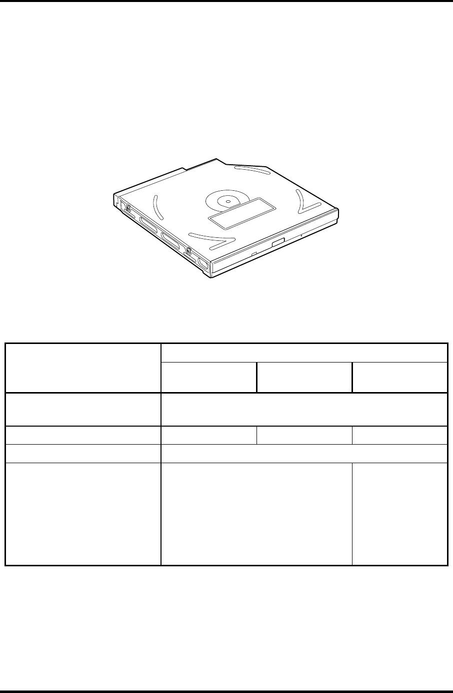
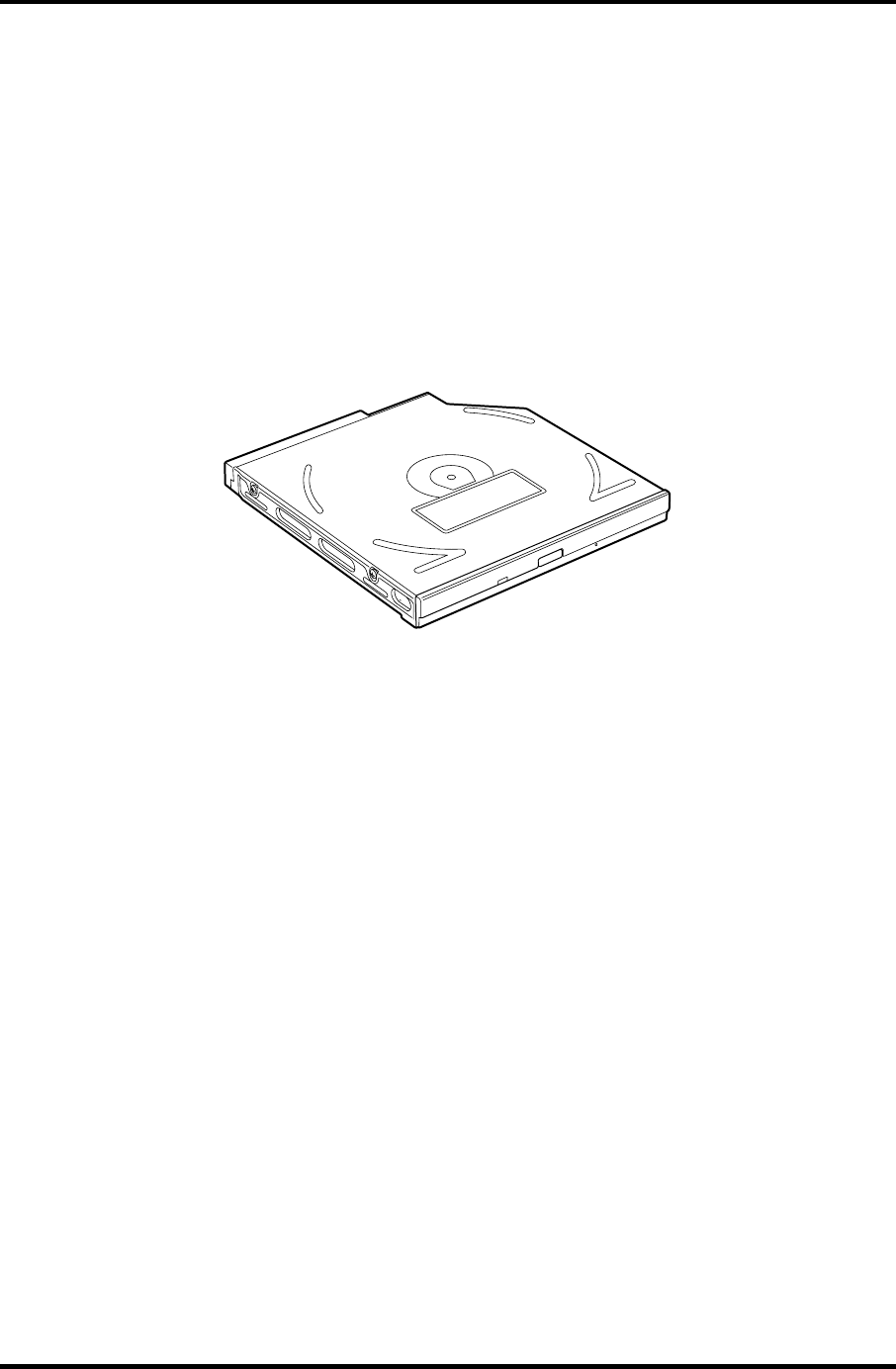
1.5 CD-RW/DVD-ROM Drive
This drive is a combination of DVD-ROM and CD-R/RW Drive. . It is full-size and runs
either 12cm (4.72-inch) or 8cm (3.15-inch) DVD/CDs without an adaptor. This drive reads
CD-ROM at maximum 24-speed, reads DVD-ROM at maximum 8-speed writes CD-R at
maximum 24-speed, and writes CD-RW at maximum 24-speed.
The CD-RW/DVD-ROM drive is shown in figure 1-6. Specifications are listed in Table 1-3.
Figure 1-6 CD-RW/DVD-ROM drive
Table 1-3 CD-RW/DVD-ROM drive specifications
Matushita G8CC0001C210
Item DVD-ROM mode CD-ROM mode CD-R/CD-RW
(Write)
ATAPI Burst (MB/s) 33.3 (Ultra DMA mode 2)
16.6 (PIO Mode 0 to 4, Multi word DMA mode 0 to 2)
Average Access time (ms) 180 typ 130 typ
Data Buffer Capacity (MB) 2
Supported Format CD:
CD-DA, CD-ROM, CD-RW, CD-R, CD-
ROM XA, Photo CD, Video CD,
CD-Extra, CD-text
DVD:
DVD-VIDEO, DVD-ROM, DVD-R (3.9G,
4.7G), DVD-RW, DVD-RAM (4.7G)
CD-R, CD-RW
1-18 Satellite M30-35 Maintenance Manual (960-455)
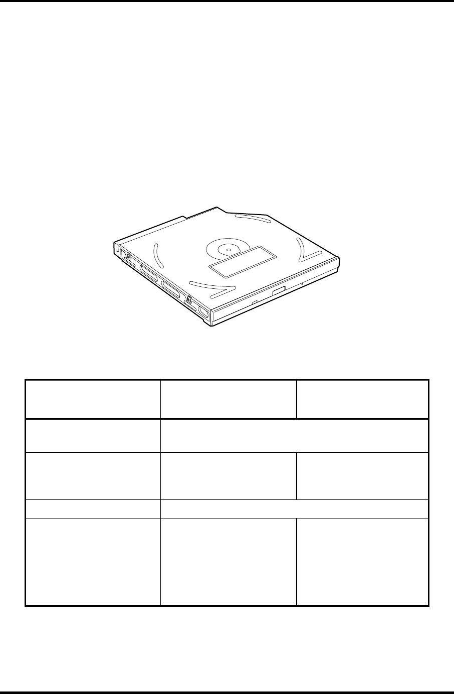
1.6 DVD-R/RW 1 Hardware Overview
1.6 DVD-R/RW
A full-size DVD-R/-RW drive module lets you record data to rewritable CD/DVDs as well
as run either 12 cm (4.72") or 8 cm (3.15") CD/DVDs without using an adaptor. It reads
DVD-ROMs at maximum 8 speed, CD-ROMs at maximum 24 speed and CD-Rs at
maximum 16 speed. It writes CD-R at up to 16 speed, CD-RW at up to 10 speed, DVD-R
and DVD-RW at single speed.
The CD-RW/DVD-ROM drive is shown in figure 1-7. Specifications are listed in Table 1-4.
Figure 1-7 DVD-R/RW drive
Satellite M30-35 Maintenance Manual (960-455) 1-19

1 Hardware Overview 1.6 DVD-R/RW
Table -4 DVD-R/RW drive specifications
Item Toshiba
SD-R6112
ATAPI Burst (MB/sec) 33.3 (Ultra DMA mode 2)
16.6 (PIO Mode 0 to 4, Multi word DMA
mode 0 to 2)
Average access time (ms)
DVD-ROM
CD-ROM
DVD-RAM
115
105
170
Data buffer (MB) 2
Speed (Read)
DVD-ROM
DVD-RAM
CD-ROM
8x
1x
24x
Speed (Write)
CD-R
CD-RW
DVD-R
DVD-RW
4x, 16x
4x,10x (High Speed)
1x, 2x
1x
Supported format (Read) CD:
CD-DA, CD+(E)G, CD-MIDI,
CD-TEXT, CD-ROM,
CD-ROM XA, CD-I,
CD-I Bridge (Photo-CD, Video-CD)
Multisession CD (Photo-CD,
CD-EXTRA, CD-R, CD-RW,
Portfolio),
CD-R, CD-RW
DVD :
DVD-ROM (DVD-5, DVD-9,
DVD-10, DVD-18)
DVD-R (Ver.1.0, Ver.2.1)
DVD-RW(Ver.1.0, Ver.1.1)
DVD-RAM(Ver.2.1)
1-20 Satellite M30-35 Maintenance Manual (960-455)
1.7 DVD-Multi (CD-R/RW DVD-RAM/R/RW) Drive 1 Hardware Overview
1.7 DVD-Multi (CD-R/RW DVD-RAM/R/RW) Drive
This drive is a combination of CD-R/RW, DVD-R/RW and DVD-RAM Drive. It is full-size
and runs either 12cm (4.72-inch) or 8cm (3.15-inch) DVD/CDs without an adaptor. This
drive reads CD-ROM at maximum 24-speed, reads DVD-ROM at maximum 8-speed writes
CD-R at maximum 16-speed, writes CD-RW at maximum 8-speed, writes DVD-R at
maximum 2-speed, writes DVD-RW at maximum 1-speed,.and writes DVD-RAM at
maximum 2-speed.
The DVD multi drive is shown in Figure 1-8. Specifications for the DVD multi drive are
described in table 1-5.
Figure 1-8 DVD-Multi drive
Table 1-5 DVD-Multi drive specifications (1/2)
Item
TEAC
G8CC00013210
Matsushita
G8CC00019210
ATAPI Burst (MB/sec) 33.3 (Ultra DMA mode 2)
16.6 (PIO Mode 0 to 4, Multi word DMA mode 0 to 2)
Average access time (ms)
DVD-ROM
CD-ROM
130 average.
110 average
180 typ. (Random)
150 typ. (Random)
Data buffer (MB) 2
Speed (Read)
DVD-ROM
DVD-Video
CD-ROM
CD-DA
DVD-RW
DVD-R/DVD-RW
8x (CAV)
4x (CAV)
24x (CAV)
8x (CLV)
4x (CAV)
4x (CAV)
8x max.
4
24x max. (CAV)
8
4
4
Satellite M30-35 Maintenance Manual (960-455) 1-21

1 Hardware Overview 1.7 DVD-Multi (CD-R/RW DVD-RAM/R/RW) Drive
Table 1-5 DVD-Multi drive specifications (2/2)
Item
TEAC
G8CC00013210
Matsushita
G8CC00019210
Speed (Write)
CD-R
CD-RW
DVD-R
DVD-RW
DVD-RAM
16x max.(ZCLV)
10x (CLV)
2x (CLV)
1x (CLV)
2x (ZLV)
16x (ZoneCLV)
8x (CLV)
2x (CLV)
1x (CLV)
2x (ZCLV) (4.7GB)
Supported format CD: CD-DA
CD-ROM
CD-ROM XA Mode 2
(Form 1, Form2)
Photo-CD
(single/multi-session)
Enhanced CD
CD-TEXT
DVD :DVD-ROM
DVD-R (General.
Authoring)
DVD-Video
DVD-RAM(4.7G,
2.6G)
CD: CD-DA
CD-ROM
CD-R/W
CD-R
CD-ROMXA
CD-I Ready
Photo-CD
Video CD
Cd-Extra(CD+)
CD-TEXT
DVD :DVD-ROM
DVD-R (3.9GB,
4.7GB)
DVD-RW(Ver. 1.1)
DVD-RAM( 2.6G,
4.7GB,9.4GB)
1-22 Satellite M30-35 Maintenance Manual (960-455)
1.8 Keyboard 1 Hardware Overview
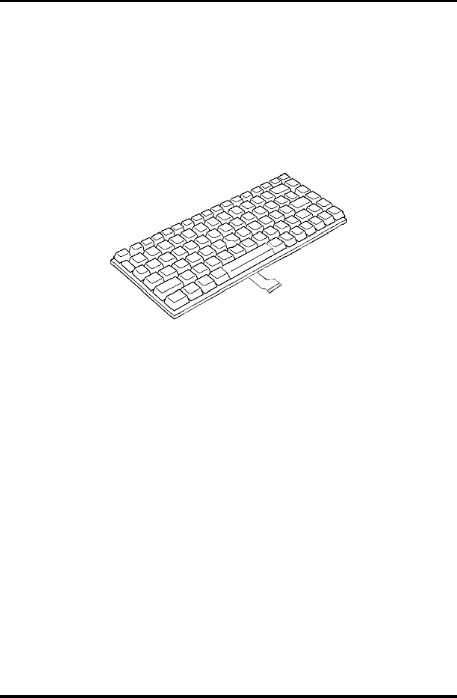
1.8 Keyboard
The keyboard is mounted 85(US)/86(UK) keys that consist of character key and control key,
and in conformity with JIS. The keyboard is connected to membrane connector on the system
board and controlled by the keyboard controller.
Figure 1-9 is a view of the keyboard.
See Appendix E about a layout of the keyboard.
Figure 1-9 Keyboard
Satellite M30-35 Maintenance Manual (960-455) 1-23
1 Hardware Overview 1.9 TFT Color Display
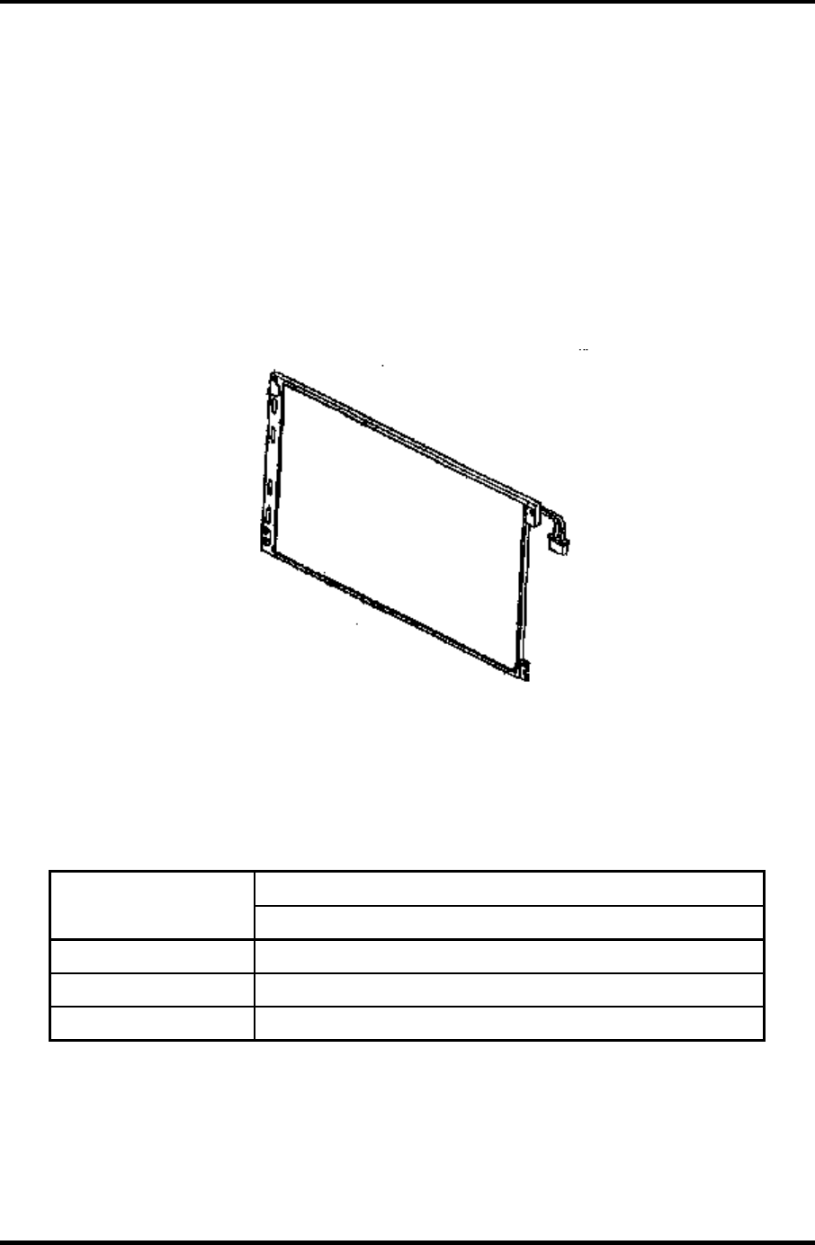
1.9 TFT Color Display
The TFT color display consists of 15.4-inch WXGA LCD module and FL inverter board.
1.9.1 LCD Module
A high-resolution external monitor connected to the computer can display up to
2048(H)×1536(V), at 16M colors.
Figure 1-10 shows a view of the LCD module and Table 1-6 lists the specifications.
Figure 1-10 LCD module
Table 1-6 LCD module specifications (1/5)
Specifications
Item
15.4-inch WXGA (G33C0001D110)
Number of Dots 1,280 (W) x 800 (H)
Dot spacing (mm) 0.25875 (H) x 0.25875 (V)
Display range (mm) 331.2 (W) x 207(H)
1-24 Satellite M30-35 Maintenance Manual (960-455)
1.9 TFT Color Display 1 Hardware Overview
Table 1-6 LCD module specifications (2/5)
Specifications
Item
15.4-inch WXGA (G33C0001F110)
Number of Dots 1,280 (W) x 800 (H)
Dot spacing (mm) 0.25875 (H) x 0.25875 (V)
Display range (mm) 332.16(H) x 207.6(V)
Table 1-6 LCD module specifications (3/5)
Specifications
Item
15.4-inch WXGA (G33C0001H110)
Number of Dots 1,280 (W) x 800 (H)
Dot spacing (mm) 0.2595 (H) x 0.2595 (V)
Display range (mm) 332.16 (W) x 207.6 (H)
Table 1-6 LCD module specifications (4/5)
Specifications
Item
15.4-inch WXGA(CSV) (G33C0001E110)
Number of Dots 1,280 (W) x 800 (H)
Dot spacing (mm) 0.25875 (H) x 0.25875 (V)
Display range (mm) 331.2 (W) x 207 (H)
Table 1-6 LCD module specifications (5/5)
Specifications
Item
15.4-inch WXGA(CSV) (G33C0001G110)
Number of Dots 1,280 (W) x 800 (H)
Dot spacing (mm) 0.25875 (H) x 0.25875 (V)
Display range (mm) 331.2 (W) x 207 (H)
Satellite M30-35 Maintenance Manual (960-455) 1-25

1 Hardware Overview 1.9 TFT Color Display
1.9.2 FL Inverter Board
The FL inverter board supplies a high frequency current to illuminate the LCD module FL.
Table 1-7 lists the FL inverter board specifications.
Table 1-7 FL inverter board specifications
Item Specifications
Voltage (V) DC 5 Input
Power (W) 7
Voltage (V) 750
Current (mA) 6.00
Output
Power (mA) 5W/7VA
1-26 Satellite M30-35 Maintenance Manual (960-455)

1.10 Power Supply 1 Hardware Overview
1.10 Power Supply
The power supply supplies many different voltages to the system board and performs the
following functions:
1. Checks power input to determine:
Whether the AC adaptor is connected to the computer •
•
•
•
•
•
•
•
•
•
•
•
•
•
•
•
•
•
Whether the battery pack is installed and supplying power
2. Checks power supply’s internal controls:
Battery pack charging: start, stop and voltage supplied to the battery pack
Power supply system: Power supplied from a DC power source (AC adaptor)
Faulty power supply: Executes forced shutdown if needed
Logic: Power supply to various circuits
Charging current to PWM control IC for battery pack charging
3. Controls the following aspects of the logic system
Power supply to gate arrays
Power on/off
4. Indicates the following:
DC IN (sets LED to orange or blue)
Battery icon (sets LED to orange or blue)
Faulty power supply by low battery
5. Interface for the following:
BIOS via EC/KBC
Function mode of power supply
6. Detects the following:
Input voltage to logic system
Input voltage, overvoltage and input/output to battery pack
Battery pack’s internal temperature
Input voltage to DC power supply (output from AC adaptor)
The power supply output rating is specified in Table 1-8.
Satellite M30-35 Maintenance Manual (960-455) 1-27

1 Hardware Overview 1.10 Power Supply
Table 1-8 Power supply output rating (1/2)
Name Voltage (V) Use
PPV 1.468-0.748 CPU
MCH1R2-
P1V 1.2 Odem
PTV 1.075 CPU, ADM1032, Odem, ICH4-M
2R5-B2V 2.5 Odem, SDRAM
2R5-P2V 2.5 NV34
1R25-B1V 1.25 SDRAM
PGV 1.2-1.5 NV34
LAN-E3V 3.3 ICH4-M, KINNERETH
S3V 3.3 ICH4-M, EC/KBC
B3V 3.3 YEBISU3S, PC Card ,MDC
P3V 3.3
Clock Generator, ICH4-M, FWH, mini-PCI, Super I/O,FIR,
IEEE 1394, LCD, STAC9750
SD-P3V 3.3 SD
E5V 5 USB
CD-E5V 5 CD-ROM
B5V 5 PC Card
P5V 5 HDD, KB,LED, Parallel, LCD
SND-E5V 5 AN12940
1R8-P1V 1.8 Odem, ICH4-M
1R5-P1V 1.5 Odem, ICH4-M, NV34
1R5-S1V 1.5 ICH4-M
LAN1R5-
E1V 1.5 ICH4-M
1-28 Satellite M30-35 Maintenance Manual (960-455)

1.10 Power Supply 1 Hardware Overview
Table 1-8 Power supply board output rating (2/2)
Name Voltage (V) Use
S5V 5 OZ168
MCV 5 PSC
A4R7-P4V 4.7
STAC9750, MIC
CDA4R7-E4V 4.7 CD, Headphone
R3V 2.0-3.3 ICH4-M
Satellite M30-35 Maintenance Manual (960-455) 1-29
1 Hardware Overview 1.11 Batteries
1.11 Batteries
The computer has three types of batteries as follows:
Main battery pack
RTC battery
The battery specifications are listed in Table 1-9.
Table 1-9 Battery specifications
Battery name Material Output voltage Capacity
Main battery Lithium-Ion (6-cell) 10.8 V 4,400mAh
Lithium-Ion (12 cell) 10.8 V 8,800mAh
RTC battery Nickel-metal hydride 2.4 V 16
1.11.1 Main Battery
The removable main battery pack is the computer’s main power source when the AC adaptor
is not attached. The main battery maintains the state of the computer when the computer
enters in resume mode.
1-30 Satellite M30-35 Maintenance Manual (960-455)
1.11 Batteries 1 Hardware Overview
1.11.2 Battery Charging Control
Battery charging is controlled by a power supply microprocessor. The microprocessor
controls whether the charge is on or off and detects a full charge when the AC adaptor and
battery are attached to the computer. The system charges the battery using quick charge.
Quick Battery Charge
When the AC adaptor is attached, there are two types of quick charge: quick charge 1 when
the system is powered off and quick charge 2 when the system is powered on.
Table 1-10 Time required for quick charges
Status Charging time
12 cell About 3.4 hours
Quick charge 1
(Power off) 6 cell About 2.7 hours
12 cell About 8.0 to 20.0 or longer Quick charge 2
(Power on)
6 cell About 4.0 to 10.0 or longer
NOTE: The time required for quick charge 2 is affected by the amount of power the system
is consuming. Use of the fluorescent lamp and frequent disk access diverts power and
lengthens the charge time.
If any of the following occurs, the battery quick charge process stops.
1. The battery becomes fully charged.
2. The AC adaptor or battery is removed.
3. The battery or output voltage is abnormal.
Detection of full charge
A full charge is detected only when the battery is charging at quick charge. A full charge is
detected under any of the following conditions:
1. The current in the battery charging circuit drops under the predetermined limit.
2. The charging time exceeds the fixed limit.
Satellite M30-35 Maintenance Manual (960-455) 1-31

1 Hardware Overview 1.11 Batteries
1-32 Satellite M30-35 Maintenance Manual (960-455)
1.11.3 RTC battery
The RTC battery provides power to keep the current date, time and other setup information
in memory while the computer is turned off. Table 1-11 lists the charging time and data
preservation period of the RTC battery.
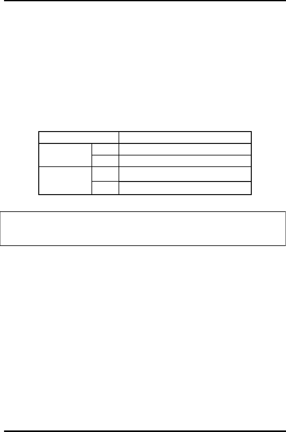
Table 1-11 RTC battery charging/data preservation time
Status Time
Charging Time (power on) 8 hours
Data preservation period (full charge) 1 month

Chapter 2
Troubleshooting Procedures

2 Troubleshooting Procedures
2-ii Satellite M30-35 Maintenance Manual (960-455)

2 Troubleshooting Procedures
Chapter 2 Contents
2.1 Troubleshooting......................................................................................................... 2-1
2.2 Troubleshooting Flowchart ....................................................................................... 2-2
2.3 Power Supply Troubleshooting ................................................................................. 2-6
Procedure 1 Power LED Check ...................................................................... 2-6
Procedure 2 Error Code Check ....................................................................... 2-8
Procedure 3 Connection Check..................................................................... 2-14
Procedure 4 Charge Check............................................................................ 2-15
Procedure 5 Replacement Check................................................................... 2-16
2.4 System Board Troubleshooting ............................................................................... 2-17
Procedure 1 Message Check ......................................................................... 2-18
Procedure 2 Debugging Port Check on Boot Mode...................................... 2-20
Procedure 3 Diagnostic Test Program Execution Check .............................. 2-28
Procedure 4 Replacement Check................................................................... 2-29
2.5 FDD Troubleshooting.............................................................................................. 2-30
Procedure 1 FDD Head Cleaning Check....................................................... 2-30
Procedure 2 Diagnostic Test Program Execution Check .............................. 2-31
Procedure 3 Connector Check and Replacement Check............................... 2-32
2.6 HDD Troubleshooting ............................................................................................. 2-33
Procedure 1 Message Check ......................................................................... 2-33
Procedure 2 Partition Check.......................................................................... 2-34
Procedure 3 Format Check............................................................................ 2-35
Procedure 4 Diagnostic Test Program Execution Check .............................. 2-36
Procedure 5 Connector Check and Replacement Check............................... 2-37
2.7 Keyboard Troubleshooting...................................................................................... 2-38
Procedure 1 Diagnostic Test Program Execution Check .............................. 2-38
Procedure 2 Connector and Replacement Check .......................................... 2-39
2.8 Display Troubleshooting ......................................................................................... 2-40
Satellite M30-35 Maintenance Manual (960-455) 2-iii

2 Troubleshooting Procedures
Procedure 1 External Monitor Check............................................................ 2-40
Procedure 2 Diagnostic Test Program Execution Check .............................. 2-40
Procedure 3 Connector and Cable Check...................................................... 2-41
Procedure 4 Replacement Check................................................................... 2-42
2.9 Optical Drive Troubleshooting................................................................................ 2-43
Procedure 1 Diagnostic Test Program Execution Check .............................. 2-43
Procedure 2 Connector Check and Replacement Check............................... 2-44
2.10 Modem Troubleshooting ......................................................................................... 2-45
Procedure 1 Diagnostic Test Program Execution Check .............................. 2-45
Procedure 2 Connector Check and Replacement Check............................... 2-46
2.11 LAN Troubleshooting ............................................................................................. 2-47
Procedure 1 Diagnostic Test Program Execution Check .............................. 2-47
Procedure 2 Connector Check and Replacement Check............................... 2-47
2.12 Wireless LAN Troubleshooting .............................................................................. 2-48
Procedure 1 Transmitting-Receiving Check ................................................. 2-48
Procedure 2 Antennas' Connection Check .................................................... 2-49
Procedure 3 Antenna Check.......................................................................... 2-50
Procedure 4 Replacement Check................................................................... 2-51
2.13 Sound Troubleshooting ........................................................................................... 2-52
Procedure 1 Diagnostic Test Program Execution Check .............................. 2-52
Procedure 2 Connector Check....................................................................... 2-53
Procedure 3 Replacement Check................................................................... 2-54
2.14 SD Card SlotTroubleshooting ................................................................................. 2-55
Procedure 1 Check on Windows ................................................................... 2-55
Procedure 2 Connector/Replacement Check................................................ 2-55
2-iv Satellite M30-35 Maintenance Manual (960-455)

2 Troubleshooting Procedures
Figures
Figure 2-1 Troubleshooting flowchart ............................................................................ 2-3
Figure 2-2 A set of tool for debug port test................................................................... 2-20
Figure 2-3 Antenna test cable ....................................................................................... 2-50
Tables
Table 2-1 Battery Icon ................................................................................................... 2-6
Table 2-2 DC IN icon .................................................................................................... 2-7
Table 2-3 Error code ...................................................................................................... 2-9
Table 2-4 Debugging port boot mode status................................................................ 2-21
Table 2-5 FDD error code and status........................................................................... 2-31
Table 2-6 Hard disk drive error code and status.......................................................... 2-36
Satellite M30-35 Maintenance Manual (960-455) 2-v

2 Troubleshooting Procedures
2-vi Satellite M30-35 Maintenance Manual (960-455)

2.1 Troubleshooting 2 Troubleshooting Procedures
2
2.1 Troubleshooting
Chapter 2 describes how to determine if a Field Replaceable Unit (FRU) in the computer is
causing the computer to malfunction. The FRUs covered are:
1. Power supply 5. Keyboard 9. LAN
2. System Board 6. Display 10. Wireless LAN
3. Floppy Disk Drive 7. Optical Drive 11. Sound components
4. Hard Disk Drive 8. Modem 12. SD Card Slot
The Diagnostics Disk operations are described in Chapter 3. Detailed Replacement
Procedures are given in Chapter 4, Replacement Procedures.
The following tools are necessary for implementing the troubleshooting procedures:
1. Diagnostics Disk
2. Phillips screwdriver (2 mm)
3. LH-STIX screwdriver (in some models)
4. Toshiba MS-DOS system disk(s)
(You must install the following onto the disk: SYS.COM, FORMAT.COM,
FDISK.COM and FDISK.EXE)
5. Formatted work disk for floppy disk drive testing
6. Cleaning kit for floppy disk drive troubleshooting
7. Parallel port wraparound connector
8. PC card wraparound connector
9. Multimeter
10. External USB FDD
11. External USB keyboard and Mouse
12. Headphone
13. Microphone
14. USB test module and USB cable
15. TOSHIBA CD-ROM TEST DISK (ZA1217P01/P000204190)
16. CD-RW Media (RICOH-made x4 recommended)
17. DVD-ROM TSD-1 (TOSHIBA-EMI DVD Test Media)
18. Music CD
19. RJ11 connector checker
20. Speaker
21. Personal computer that can communicate by wireless LAN for wireless LAN
troubleshooting
22. Antenna test cable
Satellite M30-35 Maintenance Manual (960-455) 2-1

2 Troubleshooting Procedures 2.2 Troubleshooting Flowchart
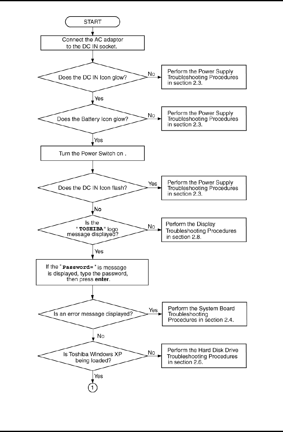
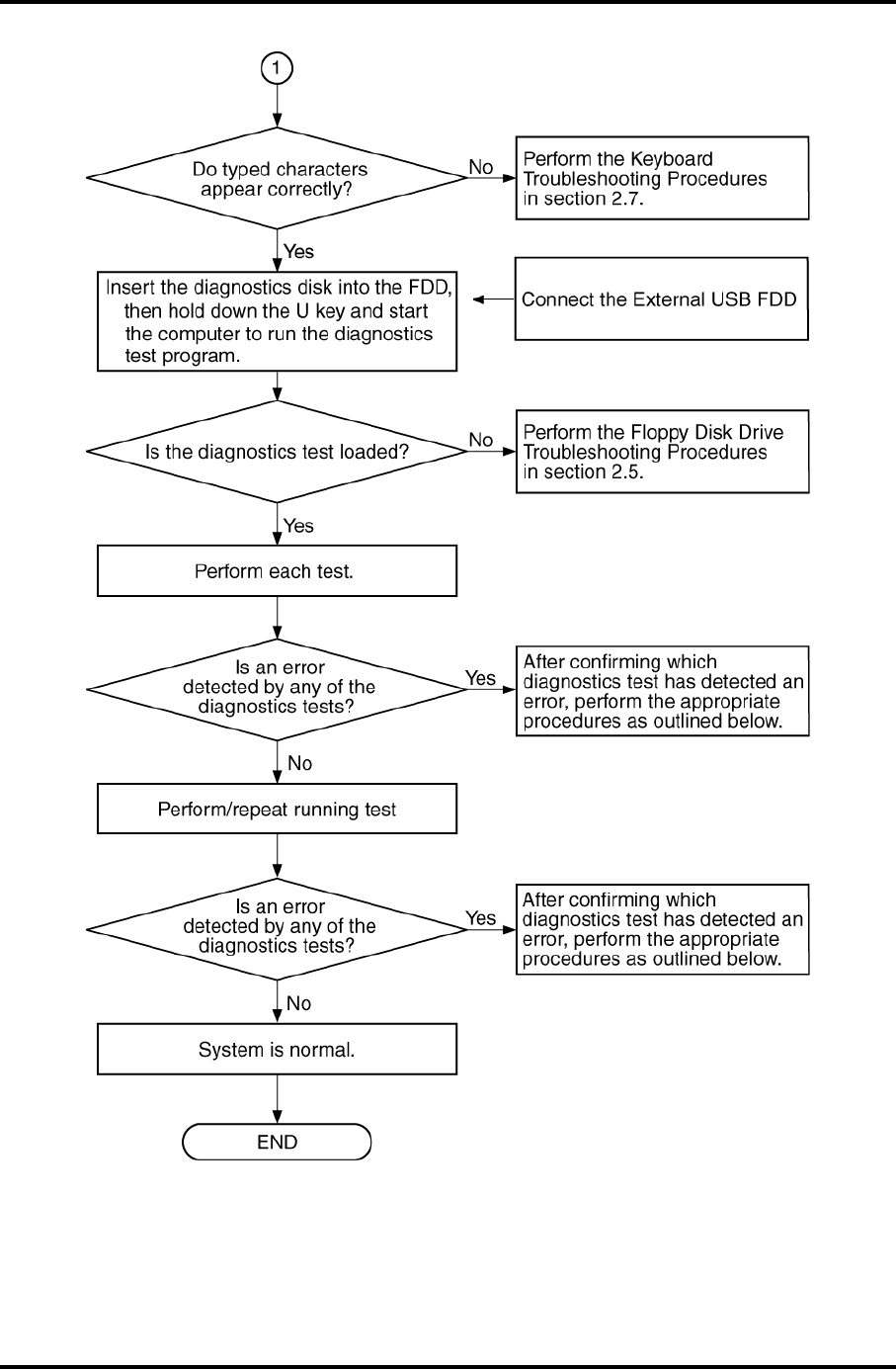
2.2 Troubleshooting Flowchart
Use the flowchart in Figure 2-1 as a guide for determining which troubleshooting procedures
to execute. Before going through the flowchart steps, verify the following:
Ask the user if a password is registered and, if it is, ask him or her to enter the
password. If the user has forgotten the system password, perform the following
procedure at the appropriate step in the flowchart in Figure 2-1:
Verify with the customer that Toshiba Windows is installed on the hard disk. Non-
Windows operating systems can cause the computer to malfunction.
Make sure all optional equipment is removed from the computer.
Make sure the External USB floppy disk drive is empty.
2-2 Satellite M30-35 Maintenance Manual (960-455)
2.2 Troubleshooting Flowchart 2 Troubleshooting Procedures
Figure 2-1 Troubleshooting flowchart (1/2)
Satellite M30-35 Maintenance Manual (960-455) 2-3
2 Troubleshooting Procedures 2.2 Troubleshooting Flowchart
Figure 2-1 Troubleshooting flowchart (2/2)
2-4 Satellite M30-35 Maintenance Manual (960-455)

2.2 Troubleshooting Flowchart 2 Troubleshooting Procedures
If the diagnostics program cannot detect an error, the problem may be intermittent. The
Running Test program should be executed several times to isolate the problem. Check the
Log Utilities function to confirm which diagnostic test detected an error, then perform the
appropriate troubleshooting procedures as follows:
1. If an error is detected on the system test, memory test, real timer test, perform the
System Board and Processor Module Troubleshooting Procedures in Section 2.4.
2. If an error is detected on the floppy disk test, perform the FDD Troubleshooting
Procedures in Section 2.5.
3. If an error is detected on the hard disk test, perform the HDD Troubleshooting
Procedures in Section 2.6.
4. If an error is detected on the keyboard test, perform the Keyboard Troubleshooting
Procedures in Section 2.7.
5. If an error is detected on the display test, perform the Display Troubleshooting
Procedures in Section 2.8.
6. If an error is detected on the Optical Drive test, perform the Optical Drive
Troubleshooting Procedures in Section 2.9.
7. If an error is detected on the modem test, perform the Modem Troubleshooting
Procedures in Section 2.10.
8. If an error is detected on the LAN test, perform the LAN Troubleshooting Procedures
in Section 2.11.
9. If an error is detected on the Wireless LAN test, perform the Wireless LAN
Troubleshooting Procedures in Section 2.12.
10. If an error is detected on the sound test, perform the Sound Troubleshooting
Procedures in Section 2.13.
11. If an error is detected on the SD card test, perform the SD card slot Troubleshooting
Procedures in Section 2.14.
Satellite M30-35 Maintenance Manual (960-455) 2-5
2 Troubleshooting Procedures 2.3 Power Supply Troubleshooting
2.3 Power Supply Troubleshooting
The power supply controls many functions and components. To determine if the power
supply is functioning properly, start with Procedure 1 and continue with the other Procedures
as instructed. The procedures described in this section are:
Procedure 1: Icon Check
Procedure 2: Error Code Check
Procedure 3: Connection Check
Procedure 4: Charge Check
Procedure 5: Replacement Check
Procedure 1 Icon Check
The following Icons indicate the power supply status:
Battery icon
DC IN icon
The power supply controller displays the power supply status through the Battery icon and
the DC IN icon as listed in the tables below. To check the power supply status, install a
battery pack and connect an AC adapter.
Table 2-1 Battery Icon
Battery LED Power supply status
Lights orange Quick charge
Lights blue Battery is fully charged and AC adapter is connected.
Blinks orange
(even intervals)
The battery level becomes low while operating the computer on battery
power.*1
Flashes orange The power switch is pressed on when the battery level is low.*2
Doesn’t light Any condition other than those above
*1 Low Battery Hibernation will be executed soon.
*2 Low Battery Hibernation has already been executed.
2-6 Satellite M30-35 Maintenance Manual (960-455)

2.3 Power Supply Troubleshooting 2 Troubleshooting Procedures
Table 2-2 DC IN icon
DC IN icon Power supply status
Lights blue DC power is being supplied from the AC adapter.
Blinks orange Power supply malfunction*3
Doesn’t light Any condition other than those above
*3 When the power supply controller detects a malfunction, the DC IN LED
blinks and an error code is displayed.
If the icon blinks, execute the followings:
1. Remove the battery and AC adapter to cut power supply to the computer.
2. Reinstall the battery and AC adapter.
If the LED still blinks, perform the followings:
Check 1 If the DC IN icon blinks orange, go to Procedure 2.
Check 2 If the DC IN icon does not light blue, go to Procedure 3.
Check 3 If the battery icon does not light orange or blue, go to Procedure 4.
Satellite M30-35 Maintenance Manual (960-455) 2-7
2 Troubleshooting Procedures 2.3 Power Supply Troubleshooting
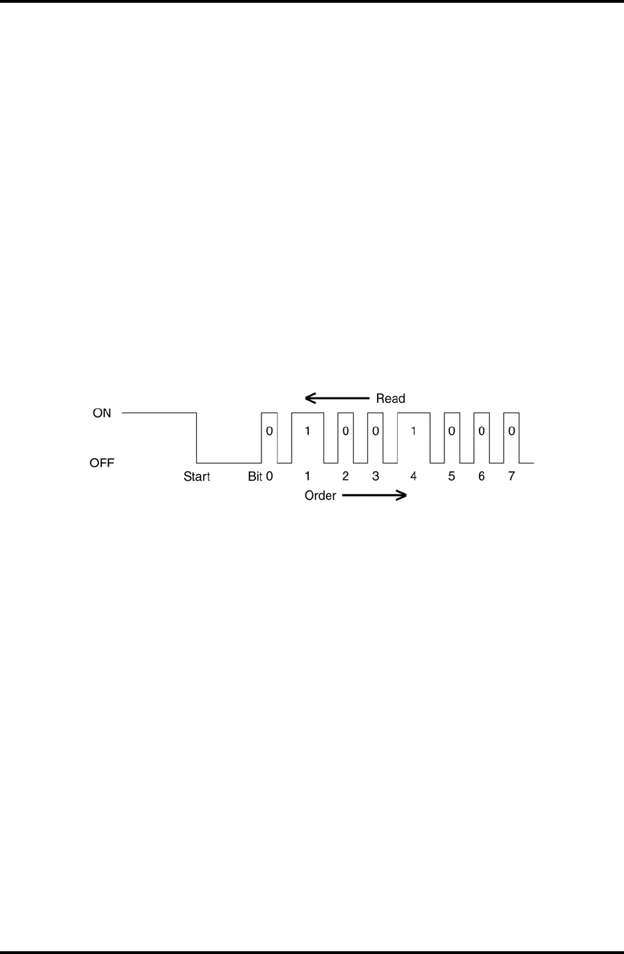
Procedure 2 Error Code Check
If the power supply microprocessor detects a malfunction, the DC IN icon blinks orange. The
blink pattern indicates an error as shown below.
Start Off for 2 seconds
Error code (8 bit)
“1” On for one second
“0” On for a half second
Interval between data bits Off for a half second
The error code begins with the least significant digit.
Example: Error code = 12h (Error codes are given in hexadecimal format.)
2-8 Satellite M30-35 Maintenance Manual (960-455)

2.3 Power Supply Troubleshooting 2 Troubleshooting Procedures
Check 1 Convert the DC IN icon blink pattern into the hexadecimal error code and
compare it to the tables below.
The error code begins with the least significant digit.
Error code
Table 2-3 Error code
Error code Where Error occurs
1*h DC Power (AC Adapter)
2*h The 1st battery
4*h S3V output (3.3V)
5*h 1R5-C1V output (1.51V)
6*h 1R8-C1V output (1.804V)
7*h PPV output (CPU core voltage)
8*h 1R2-P1V output (1.21V)
9*h E5V output (5.0V)
A*h E3V output (3.3V)
B*h 2R5-P2V output (for VGA: 2.51V)
C*h PGV output (for VGA core: 1.20V)
D*h 1R25-P1V output (1.251V)
E*h 2R5-B2V output (2.51V)
Satellite M30-35 Maintenance Manual (960-455) 2-9
2 Troubleshooting Procedures 2.3 Power Supply Troubleshooting
Check 1 Compare the patterns in the hexadecimal error code to the tables below.
DC IN
Error code Meaning
10h AC Adaptor output voltage is over 16.5 V.
11h Advanced Port Replicator output voltage is over 16.5 V.
12h Current from the DC power supply is over the limit (7.00 A).
13h Current from the DC power supply is over the limit (0.5 A), when there
is no load.
14h Current sensing IC is not normal, when there is no load.
Main Battery
Error code Meaning
20h Over voltage has been detected.
21h Main battery charge current is over 7.00 A.
22h Main battery discharge current is over 0.5 A, when there is no load.
23h Main battery charge current is over 4.3 A, when the AC adapter is not
directly connected.
24h Current sensing IC is not normal, when there is no load.
25h Main battery charge current is over 0.3 A.
S3V output
Error code Meaning
40h S3V voltage is 3.14 V or under, when the computer is powered on/off.
45h S3V voltage is 3.14 V or under at power on.
1R5-C1V output
Error code Meaning
50h 1R5-C1V voltage is over 1.80 V, when the computer is powered on/off.
51h 1R5-C1V voltage is 1.275V or under, when the computer is powered
on.
52h 1R5-C1V voltage is 1.275V or under, when the computer is booting up.
53h 1R5-C1V voltage is 1.275V or under, when the computer is
suspended.
54h 1R5-C1V voltage is not normal, when the computer is suspended.
55h 1R5-C1V voltage is 1.275V or under at power on.
2-10 Satellite M30-35 Maintenance Manual (960-455)
2.3 Power Supply Troubleshooting 2 Troubleshooting Procedures
1R8-C1V output
Error code Meaning
60h 1R8-C1V voltage is over 2.16 V, when the computer is powered on/off.
61h 1R8-C1V voltage is 1.53 V or under, when the computer is powered
on.
62h 1R8-C1V voltage is 1.53 V or under, when the computer is booting up.
63h 1R8-C1V voltage is 1.53 V or under, when the computer is suspended.
64h 1R8-C1V voltage is not normal, when the computer is suspended.
65h 1R8-C1V voltage is 1.53V or under at power on.
PPV output
Error code Meaning
70h PPV voltage is over 1.80 V, when the computer is powered on/off.
71h PPV voltage is 0.56 V or under, when the computer is powered on.
72h PPV voltage is 0.56 V or under, when the computer is booting up.
73h PPV voltage is 0.56 V or over, when the computer is powered off.
1R2-P1V output
Error code Meaning
80h 1R2-P1V voltage is over 1.44 V, when the computer is powered on/off.
81h 1R2-P1V voltage is 1.02 V or under, when the computer is powered
on.
82h 1R2-P1V voltage is 1.02 V or under, when the computer is booting up.
83h 1R2-P1V voltage is 1.02 V or over, when the computer is powered off.
84h 1R2-P1V voltage is 1.02 V or under, when the computer is suspended.
E5V output
Error code Meaning
90h E5V voltage is over 6.00V, when the computer is powered on/off.
91h E5V voltage is 4.50 V or under, when the computer is powered on.
92h E5V voltage is 4.50 V or under, when the computer is booting up.
93h E5V voltage is 4.50 V or over, when the computer is powered off.
94h E5V voltage is 4.50 V or under, when the computer is suspended.
Satellite M30-35 Maintenance Manual (960-455) 2-11
2 Troubleshooting Procedures 2.3 Power Supply Troubleshooting
E3V output
Error code Meaning
A0h E3V voltage is over 3.96 V, when the computer is powered on/off.
A1h E3V voltage is 2.81 V or under, when the computer is powered on.
A2h E3V voltage is 2 .81 V or under, when the computer is booting up.
A3h E3V voltage is 2.81 V or over, when the computer is powered off.
A4h E3V voltage is 2.81 V or under when the computer is suspended.
2R5-P2V output
Error code Meaning
B0h 2R5-P2V voltage is over 3.00 V, when the computer is powered on/off.
B1h 2R5-P2V voltage is 2.125 V or under, when the computer is powered
on.
B2h 2R5-P2V voltage is 2.125 V or under, when the computer is booting
up.
B3h 2R5-P2V voltage is 2.125 V or over, when the computer is powered
off.
PGV output
Error code Meaning
C0h PGV voltage is over 1.62V, when the computer is powered on/off.
C1h PGV voltage is 2.125 V or under, when the computer is powered on.
C2h PGV voltage is 2.125 V or under, when the computer is booting up.
C3h PGV voltage is 2.125 V or over, when the computer is powered off.
C4h PGV voltage is 2.125 V or under when the computer is suspended.
2-12 Satellite M30-35 Maintenance Manual (960-455)
2.3 Power Supply Troubleshooting 2 Troubleshooting Procedures
1R25-P1V output
Error code Meaning
D0h 1R25-P1V voltage is over 1.50 V, when the computer is powered
on/off.
D1h 1R25-P1V voltage is 1.063 V or under, when the computer is powered
on.
D2h 1R25-P1V voltage 1.063 V or under, when the computer is booting up.
D3h 1R25-P1V voltage is 1.063 V or over, when the computer is powered
off.
D4h 1R25-P1V voltage is 1.063 V or under, when the computer is
suspended.
2R5-B2V output
Error code Meaning
E0h 2R5-B2V voltage is over 3.00 V, when the computer is powered on/off.
E1h 2R5-B2V voltage is 2.125 V or under, when the computer is powered
on.
E2h 2R5-B2V voltage is 2.125V or under, when the computer is booting up.
E3h 2R5-B2V voltage is 2.125 V or over, when the computer is powered
off.
E4h 2R5-B2V voltage is 2.125 V or under when the computer is
suspended.
Check 2 In the case of error code 10h or 12h:
Make sure the AC adaptor cord and AC power cord are firmly plugged into
the DC IN 15 V socket and wall outlet. If the cables are connected correctly,
go to the following step:
Connect a new AC adaptor and/or AC power cord, if necessary. If the error
still exists, go to Procedure 5.
Check 3 In the case of error code 2Xh:
Make sure the battery pack is correctly installed in the computer. If the battery
pack is correctly installed, go to the following step:
Replace the battery pack with a new one. If the error still exists, go to
Procedure 5.
Check 4 For any other error, go to Procedure 5.
Satellite M30-35 Maintenance Manual (960-455) 2-13
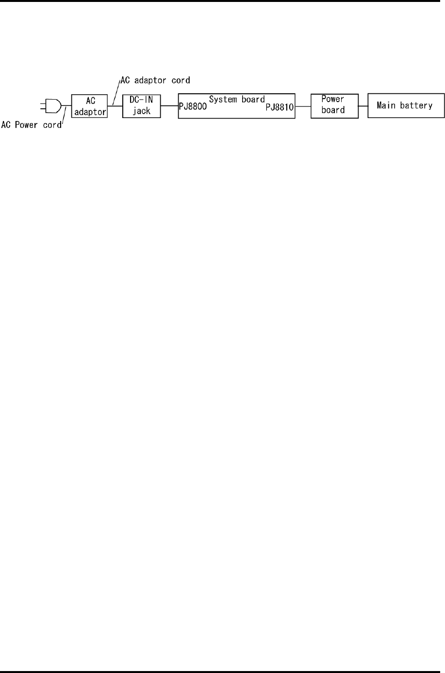
2 Troubleshooting Procedures 2.3 Power Supply Troubleshooting
Procedure 3 Connection Check
The power supply wiring diagram is shown below:
Any of the connectors may be disconnected. Perform Check 1.
Check 1 Disconnect the AC power cord from the wall outlet. Check the power cable for
breaks. If the power cord is damaged, connect a new AC power cord. If there is no
damage, go to Check 2.
Check 2 Make sure the AC adaptor cord and AC power cord are firmly plugged into the
PJ8800 DC IN 15 V socket and AC adaptor inlet/wall outlet, respectively. If these
cables are connected correctly, go to Check 3.
Check 3 Make sure the DC IN input port where an AC adaptor’s DC output plug is
connected is firmly secured to the system board.
• If the DC IN input port is loose, go to Procedure 5.
• If it is not loose, go to Check 4.
Check 4 Use a multimeter to make sure the AC adaptor output voltage is close to 15 V. If
the output is several percent lower than 15 V, go to Check 5. If the output is close
to 15 V, go to Check 6.
Check 5 Connect a new AC adaptor or AC power cord.
• If the DC IN icon does not light, go to Procedure 5.
• If the battery icon does not light, go to Check 6.
Check 6 Make sure the battery pack is installed in the computer correctly. If the battery is
properly installed and the battery icon still does not light, go to Procedure 4.
2-14 Satellite M30-35 Maintenance Manual (960-455)
2.3 Power Supply Troubleshooting 2 Troubleshooting Procedures
Procedure 4 Charge Check
The power supply may not charge the battery pack. Perform the following procedures:
1. Reinstall the battery pack.
2. Attach the AC adaptor and turn on the power. If you cannot turn on the power, go to
Procedure 5.
3. Run the Diagnostic test, go to System test and execute subtest 06 (Quick charge)
described in Chapter 3.
4. When charge is complete, the diagnostics test displays the result code. Check the
result code against the table below and perform any necessary check.
Result code Contents Check items
0 The battery is charging normally. Normal
1 The battery is fully charged. Normal
2 The AC adaptor is not connected. Check 1
3 The AC adaptor’s output voltage is not normal. Check 1
4 The battery is not installed. Check 2
5 The battery’s output voltage is not normal. Check 3
6 The battery’s temperature is not normal. Check 4
7 A bad battery is installed. Check 2
8 Any other problems. Check 5
Check 1 Make sure the AC adaptor and AC power cord are firmly plugged into the DC IN
socket and the wall outlet. If these cables are connected correctly, replace the AC
adaptor (and/or AC power cord, if necessary).
Check 2 Make sure the battery is properly installed. If the battery is properly installed, go
to Check 3.
Check 3 The battery pack may be completely discharged. Wait a few minutes to charge the
battery pack. If the battery pack is still not charged, go to Check 4.
Check 4 The battery’s temperature is too hot or cold. Return the temperature to a normal
operating condition. If the battery pack still is not charged, go to Check 5.
Check 5 Replace the battery pack with a new one. If the battery pack still is not charged,
go to Procedure 5.
Satellite M30-35 Maintenance Manual (960-455) 2-15

2 Troubleshooting Procedures 2.3 Power Supply Troubleshooting
Procedure 5 Replacement Check
The system board processor module may be disconnected or damaged. Disassemble the
computer following the steps described in Chapter 4, Replacement Procedures. Check the
connection between the AC adaptor and system board. After checking the connections,
perform the following Check 1:
Check 1 Replace the AC adaptor with a new one. If the AC adaptor still does not function
properly, perform Check 2.
Check 2 Replace the system board with a new one following the steps described in Chapter
4, Replacement Procedures.
2-16 Satellite M30-35 Maintenance Manual (960-455)

2.4 System Board Troubleshooting 2 Troubleshooting Procedures
2.4 System Board Troubleshooting
This section describes how to determine if the system board is defective or not. Start with
Procedure 1 and continue with the other procedures as instructed. The procedures described
in this section are:
Procedure 1: Message Check
Procedure 2: Debugging port status Check
Procedure 3: Diagnostic Test Program Execution Check
Procedure 4: Replacement Check
Satellite M30-35 Maintenance Manual (960-455) 2-17

2 Troubleshooting Procedures 2.4 System Board Troubleshooting
Procedure 1 Message Check
When the power is turned on, the system performs the Initial Reliability Test (IRT) installed
in the BIOS ROM. The IRT tests each IC on the system board and initializes it.
If an error message is shown on the display, perform Check 1.
If nothing is displayed, go to Procedure 2.
If an operating system is properly loaded, go to Procedure 4.
Check 1 If one of the following error messages displays on the screen, press the Run
Setup key as the message instructs. These errors occur, when the system
configuration preserved in the RTC memory (CMOS type memory) is not the
same as the actual configuration or when the data is lost.
If you press the Run Setup key as the message instructs, the SETUP screen
appears to set the system configuration. If any error message is displayed, perform
Check 2.
If error message (a) appears often when the power is turned on, replace the RTC
battery. If any other error message displays, perform Check 2.
(a) 0250: RTC battery is low
(b) 0251: CMOS checksum is inconsistent
(c) 0271: Check date and time settings
(d) 0290: ROM data is invalid
Check 2 If the following error message appears on the screen, press the Continue key as
the message instructs. This error occurs, when consumption of battery or failure
of system board loses the resumed data. Go to Procedure 3.
WARNING: RESUME FAILURE.
If any other error message displays, perform Check 3.
2-18 Satellite M30-35 Maintenance Manual (960-455)

2.4 System Board Troubleshooting 2 Troubleshooting Procedures
Check 3 The IRT checks the system board. When the IRT detects an error, the system
stops or an error message appears.
If error message (5) appears, go to the Keyboard Troubleshooting Procedures in
Section 2.7.
If error message (1), (2), (3) or (4) appears, go to the HDD Troubleshooting
Procedures in Section 2.6.
If error message (7) appears, go to the FDD Troubleshooting Procedures in
Section 2.5.
(1) 0201: Failure IDE#0
(2) 0202: Failure IDE#1
(3) 0203: Failure IDE#2
(4) 0204: Failure IDE#3
(5) 0212: Keyboard Controller Failed
(6) 0260: System timer error
(7) 02B0: Diskette drive A error
Satellite M30-35 Maintenance Manual (960-455) 2-19
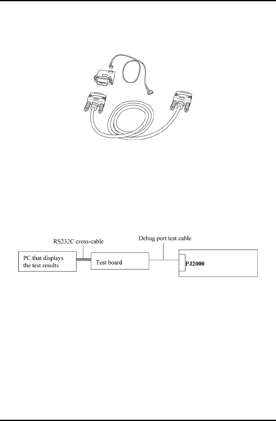
2 Troubleshooting Procedures 2.4 System Board Troubleshooting
Procedure 2 Debugging Port Check on Boot Mode
Check the D port status by a debug port test. The tool for debug port test is shown below.
Figure 2-2 A set of tool for debug port test
The test procedures are follows;
1. Connect the debug test cable to the connector PJ2000 of the system board. For
disassembling to connect the test cable, refer to Chapter 4.
2. Connect the debug port test cable and RS-232C cross-cable to the test board.
3. Connect the RS-232C cross-cable to the PC that displays the results.
System board
4. Boot the computer in MS-DOS mode.
2-20 Satellite M30-35 Maintenance Manual (960-455)
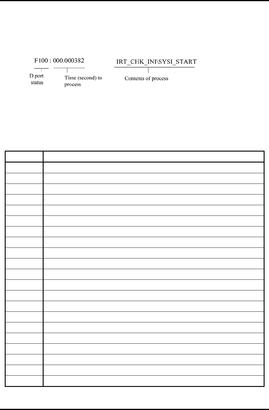
2.4 System Board Troubleshooting 2 Troubleshooting Procedures
5. Execute GETDPORT.COM in the text menu in CPU REAL mode. (Insert the FD for
starting D port into FDD and input “FD starting drive:>dport”.)
The D port status is displayed in the following form;
6. When the D port status is FFFFh (normal status), go to Procedure 3.
7. When the D port status falls into any status in Table 2-4, execute Check 1.
Table 2-4 Debugging port boot mode status (1/7)
Debug Port Description
0000h
0080h Initialize the chipset
0081h Initialize the bridge
0082h Initialize the CPU
0083h Initialize system timer
0084h Initialize system I/O
0085h Check for BIOS changing
0087h Go to BIOS
0088h Initialize Multi Processor
0089h Set segments to 4GB
008Ah Initialize specific HW
008Bh Initialize PIC and DMA
008Ch Initialize Memory type
008Dh Initialize Memory size
008Eh Shadow Boot Block
0090h System memory test
0091h Initialize interrupt vectors
0094h Output one beep
0095h Initialize the boot device
0096h Reset segments to 64KB
0097h Boot BIOS change utility
Satellite M30-35 Maintenance Manual (960-455) 2-21

2 Troubleshooting Procedures 2.4 System Board Troubleshooting
Table 2-4 Debugging port boot mode status (2/7)
Debug Port Description
0098h Initialize USB Controller
0101h
0102h Verify Real Mode. If the CPU is in protected mode, turn on A20 and pulse the
reset line, forcing a shutdown 0.
0103h Disable Non-Maskable Interrupts.
0104h Get CPU type from CPU registers and save it.
0106h Initialize system hardware. Reset the DMA controllers, disable the videos, clear
any pending interrupts from the real-time clock and set up port B register.
0107h Disable system ROM shadow and start to execute ROM code from the flash part.
0108h Initialize chip set registers to the initial values.
0109h Set in-POST flag in CMOS that indicates we are in POST.
010Ah Initialize CPU registers.
010Bh
010Ch Initialize cache.
010Eh
010Fh
0110h
0111h Load alternate registers with initial table values
0112h Restore the contents of the CPU control word whenever the CPU is reset.
0113h Reset PCI devices in early post
0114h
0116h Verify that the ROM BIOS checksums to zero
0117h Initialize external cache before autosizing memory.
0118h Initialize PIT(Programmable Interval Timer).
011Ah Initialize DMA.
011Ch Initialize interrupt controllers for some shutdowns.
011Fh
0120h Verify that DRAM refresh is operating by polling the refresh bit in PORTB.
0122h
0124h Set segment-register addressibility to 4 GB
0128h Determine DRAM size and configure the chipset accordingly. Before autosizing,
all caches and all shadow RAM are disabled.
2-22 Satellite M30-35 Maintenance Manual (960-455)

2.4 System Board Troubleshooting 2 Troubleshooting Procedures
Table 2-4 Debugging port boot mode status (3/7)
Debug Port Description
0129h Initialize the POST Memory Manager
012Ah Zero clear the first 512K of RAM
012Bh
012Ch Test 512K base address lines
012Eh Test the first 4MB of RAM.
012Fh Initialize external cache before shadowing.
0132h Compute CPU speed.
0133h Initialize the Phoenix Dispatch Manager
0134h Test the CMOS RAM and RTC
0136h Vector to proper shutdown routine.
0138h Shadow the system BIOS.
013Ah External cache is autosized and its configuration saved in memory.
013Bh
013Ch If CMOS is valid, load chipset registers with values from CMOS, otherwise load
defaults.
013Dh Load alternate registers with CMOS values.
013Fh
0141h
0142h Initialize interrupt vectors 0 thru 77h to the BIOS general interrupt handler.
0145h Initialize all motherboard devices.
0146h Verify the ROM copyright notice
0148h Verify that the equipment specified in the CMOS matches the hardware currently
installed.
0149h Initialize all PCI devices.
014Ah Initialize video chip in system
014Bh
014Ch Shadow video BIOS ROM.
014Eh Display copyright notice.
014Fh Initialize MultiBoot. Allocate memory for old and new MultiBoot history tables.
0150h Display CPU type and speed.
0151h
Satellite M30-35 Maintenance Manual (960-455) 2-23

2 Troubleshooting Procedures 2.4 System Board Troubleshooting
0152h
Table 2-4 Debugging port boot mode status (4/7)
Debug Port Description
0154h
0155h
0157h
0158h Test for unexpected interrupts.
0159h Initialize the POST display service.
015Ah Display prompt "Press F2 for SETUP"
015Bh Disable L1 cache during POST
015Ch Test RAM between 512K and 640K.
0160h Determine the amount of extended memory available.
0162h
0164h
0166h
0167h
0168h
0169h Initialize the handler for SMM.
016Ah
016Ch Display shadow message.
0170h Display error messages on the screen.
0172h Check status bits to see if configuration problems were detected. If so, Display
error messages on the screen.
0176h
017Ch Initialize the hardware interrupt vectors from 08 to 0F and from 70h to 77H. Also
set the interrupt vectors from 60h to 66H to zero.
017Dh
017Eh The Coprocessor initialization test.
0180h
0181h Run late device initialization routines.
0182h
0183h Configure Fisk Disk Controller.
0184h
2-24 Satellite M30-35 Maintenance Manual (960-455)
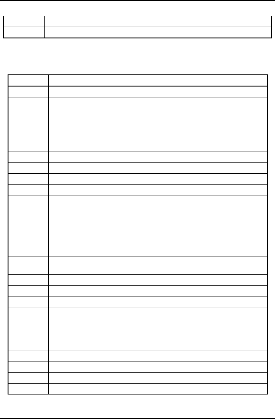
2.4 System Board Troubleshooting 2 Troubleshooting Procedures
0185h Configure all PnP ISA devices.
0186h
Table 2-4 Debugging port boot mode status (5/7)
Debug Port Description
0187h Configure motherboard configurable devices.
0188h Initialize timeouts, key buffer, and soft reset flag.
0189h Enable non-maskable interrupts.
018Ah Initialize Extended BIOS Data Area and initialize the mouse.
018Bh
018Ch Initialize the floppy disk and display an error message if failure was detected.
018Fh
0190h Initialize hard-disk controller.
0191h Configure the local bus IDE timing register based on the drives attached to it.
0192h
0193h
0195h Initialize CD-ROM drive.
0196h Reset segment-register addressibility from 4GB to normal 64K by generating a
Shutdown 8.
0197h
0198h Search for option ROMs.
0199h Check support status for Self-Monitoring Analysis Reporting Technology (disk-
failure warning).
019Bh
019Ch Perform late SMM initialization.
019Dh Initialize Security Engine.
019Eh Enable hardware interrupts.
019Fh
01A0h Verify that the system clock is interrupting.
01A2h Setup Numlock indicator.
01A4h
01A8h Remove "Press F2" prompt from the screen.
01AAh
01ACh Enter SETUP.
Satellite M30-35 Maintenance Manual (960-455) 2-25

2 Troubleshooting Procedures 2.4 System Board Troubleshooting
01AEh Clear CMOS flags for post.
2-26 Satellite M30-35 Maintenance Manual (960-455)

2.4 System Board Troubleshooting 2 Troubleshooting Procedures
Table 2-4 Debugging port boot mode status (6/7)
Debug Port Description
01B0h Check for errors.
01B1h
01B2h Change status bits in CMOS and/or the BIOS data area to reflect the fact that
POST is complete.
01B3h
01B5h Fade out logo screen.
01B6h
01B7h Initialize ACPI BIOS.
01B9h Clear all screen graphics before booting.
01BAh Initialize the SMBIOS header and sub-structures.
01BCh Clear parity-error latch
01BDh
01BEh Clear the screen before booting.
01BFh
01C1h Initialize error handler
01C2h Save the current boot type into CMOS
01C3h Check the requested boot type
01C4h Initializes (clears) the system error flags
01C5h Mark the fact that we are no longer in POST
01C6h
01C7h
01C8h
01C9h Check (and do) if BIOS change is necessary
01CAh
01CBh
01CCh Restore the memory configuration.
01CDh
01CEh
01D1h Initialize BIOS stack area
01D3h Clear memory
01D4h Determines if the CPU supports the Extended CPUID function for Processor
Name/Brand String.
01D6h
Satellite M30-35 Maintenance Manual (960-455) 2-27
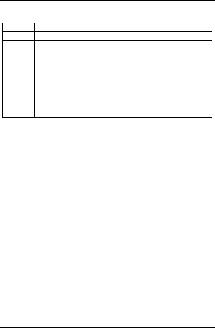
2 Troubleshooting Procedures 2.4 System Board Troubleshooting
Table 2-4 Debugging port boot mode status (7/7)
Debug Port Description
01D7h
01D8h
20FFh Try to boot with INT 19h.
03B0h
05B1h
05B2h
05B3h
05B4h
05B5h
06BFh
2-28 Satellite M30-35 Maintenance Manual (960-455)

2.4 System Board Troubleshooting 2 Troubleshooting Procedures
Procedure 3 Diagnostic Test Program Execution Check
Execute the following tests from the Diagnostic Test Menu. Refer to Chapter 3, Tests and
Diagnostics, for more information on how to perform these tests.
1. System test
2. Memory test
3. Keyboard test
4. Display test
5. Floppy Disk test
6. Printer test
7. Async test
8. Hard Disk test
9. Real Timer test
10. NDP test
11. Expansion test
12. CD-ROM/DVD-ROM test
13. Wireless LAN test
14. Sound/LAN/Modem test
15. IEEE1394
If an error is detected during these tests, go to Procedure 4.
Satellite M30-35 Maintenance Manual (960-455) 2-29

2 Troubleshooting Procedures 2.4 System Board Troubleshooting
Procedure 4 Replacement Check
The system board connectors may be disconnected. Disassemble the computer following the
steps described in Chapter 4, Replacement Procedures and perform Check 1.
Check 1 Visually check for the following:
a) Cracked or broken connector housing
b) Damaged connector pins
If connectors are in good condition, but there is still a problem, go to Check 2.
Check 2 The system board may be damaged. Replace the system board with a new one
following the steps described in Chapter 4, Replacement Procedures.
2-30 Satellite M30-35 Maintenance Manual (960-455)

2.5 FDD Troubleshooting 2 Troubleshooting Procedures
2.5 FDD Troubleshooting
This section describes how to determine if the FDD is functioning properly. Perform the
steps below starting with Procedure 1 and continuing with the other procedures as required.
Procedure 1: FDD Head Cleaning Check
Procedure 2: Diagnostic Test Program Execution Check
Procedure 3: Connector Check and Replacement Check
Procedure 1 FDD Head Cleaning Check
FDD head cleaning operation details are given in Chapter 3, Tests and Diagnostics.
Insert the Diagnostics Disk in the computer’s floppy disk drive, turn on the computer and run
the test. Clean the FDD heads using the cleaning kit. If the FDD still does not function
properly after cleaning, go to Procedure 2.
If the test program cannot be executed, go to Procedure 3.
Satellite M30-35 Maintenance Manual (960-455) 2-31

2 Troubleshooting Procedures 2.5 FDD Troubleshooting
Procedure 2 Diagnostic Test Program Execution Check
Insert the Diagnostics Disk in the FDD, turn on the computer and run the test. Refer to
Chapter 3, Tests and Diagnostics, for more information about the diagnostics test procedures.
Floppy disk drive test error codes and their status names are listed in Table 2-5. Make sure
the floppy disk is formatted correctly and that the write protect tab is disabled. If any other
errors occur while executing the FDD diagnostics test, go to Check 1.
Table 2-5 FDD error code and status
Code Status
01h Bad command
02h Address mark not found
03h Write protected
04h Record not found
06h Media removed on dual attach card
08h DMA overrun error
09h DMA boundary error
10h CRC error
20h FDC error
40h Seek error
60h No FDD
80h Time out error (Not ready)
EEh Write buffer error
FFh Data compare error
Check 1 If the following message displays, release the write protect tab on the floppy disk.
If any other message appears, perform Check 2.
FDD-Write protected
Check 2 Make sure the floppy disk is formatted correctly. If it is, go to Procedure 3.
2-32 Satellite M30-35 Maintenance Manual (960-455)
2.5 FDD Troubleshooting 2 Troubleshooting Procedures
Procedure 3 Connector Check and Replacement Check
The 3.5inch FDD is connected to the System Board via USB port.
Check 1 Make sure the USB cable is securely connected to the FDD. Also, make sure the
USB cable of the FDD is securely connected to the system board.
If any of the connections are loose, reconnect firmly and repeat Procedure 2.
If any connector is damaged, replace it with a new one and repeat Procedure 2.
If there is still an error, go to Check 2.
Check 2 The FDD cable may be defective or damaged. Replace it with a new one. If the
FDD is still not functioning properly, perform Check 3.
Check 3 Replace the System board with a new one following the steps in Chapter 4,
Replacement Procedures.
Satellite M30-35 Maintenance Manual (960-455) 2-33

2 Troubleshooting Procedures 2.6 HDD Troubleshooting
2.6 HDD Troubleshooting
This section describes how to determine if the HDD is functioning properly. Perform the
steps below starting with Procedure 1 and continuing with the other procedures as required.
Procedure 1: Message Check
Procedure 2: Partition Check
Procedure 3: Format Check
Procedure 4: Diagnostic Test Program Execution Check
Procedure 5: Connector Check and Replacement Check
CAUTION: The contents of the hard disk will be erased when you execute the HDD
troubleshooting procedures. Transfer the contents of the hard disk to floppy
disks or other storage media.
Procedure 1 Message Check
When the computer’s HDD does not function properly, some of the following error messages
may appear on the display. Start with Check 1 below and perform the other checks as
instructed.
Check 1 If any of the following messages appear, go to Procedure 5. If the following
messages do not appear, perform Check 2.
HDC ERROR (After 5 seconds this message will disappear.)
or
IDE #0 ERROR (After 5 seconds this message will disappear.)
or
IDE #1 ERROR (After 5 seconds this message will disappear.)
Check 2 If either of the following messages appears, go to Procedure 2. If the following
messages do not appear, perform Check 3.
Insert system disk in drive
Press any key when ready .....
or
Non-System disk or disk error
Replace and press any key
Check 3 Make sure the Hard Disk option is set to not used. If it is set to not used, choose
another setting and restart the computer. If the problem still exists, go to
Procedure 2.
2-34 Satellite M30-35 Maintenance Manual (960-455)

2.6 HDD Troubleshooting 2 Troubleshooting Procedures
Procedure 2 Partition Check
Insert the Toshiba MS-DOS system disk and restart the computer with U key holding down.
Perform the following checks:
Check 1 Type C: and press Enter. If you cannot change to drive C, go to Check 2. If you
can change to drive C, go to Check 3.
Check 2 Type FDISK and press Enter. Choose Display Partition Information from the
FDISK menu. If drive C is listed, go to Check 3. If drive C is not listed, return to
the FDISK menu and choose the option to create a DOS partition on drive C.
Restart the computer from the Toshiba MS-DOS system disk. If the problem still
exists, go to Procedure 3.
Check 3 If drive C is listed as active in the FDISK menu, go to Check 4. If drive C is not
listed as active, return to the FDISK menu and choose the option to set the active
partition for drive C. Restart the computer and then go to Procedure 3.
Check 4 Remove the FD and restart the computer. If the problem still exists, go to
Procedure 3.
Satellite M30-35 Maintenance Manual (960-455) 2-35

2 Troubleshooting Procedures 2.6 HDD Troubleshooting
Procedure 3 Format Check
The computer’s HDD is formatted using the low level format program and the MS-DOS
FORMAT program. To format the HDD, start with Check 1 below and perform the other
steps as required.
Check 1 Format the HDD and transfer system files using FORMAT C:/S/U. If the
following message appears on the display, the HDD is formatted.
Format complete
If an error message appears on the display, refer to the Toshiba MS-DOS Manual
for more information and perform Check 2.
Check 2 Using the Diagnostics Disk, format the HDD with a low level format option.
Refer to Chapter 3, Tests and Diagnostics for more information about the
diagnostic program.
If the following message appears on the display, the HDD low level format is
complete. Partition and format the HDD using the MS-DOS FORMAT command.
Format complete
If you cannot format the HDD using the Tests and Diagnostic program, go to
Procedure 4.
2-36 Satellite M30-35 Maintenance Manual (960-455)
2.6 HDD Troubleshooting 2 Troubleshooting Procedures
Procedure 4 Diagnostic Test Program Execution Check
The HDD test program is stored in the Diagnostics Disk. Perform all of the HDD tests in the
Hard Disk Drive Test. Refer to Chapter 3, Tests and Diagnostics, for more information about
the HDD test program.
If an error is detected during the HDD test, an error code and status will be displayed.
Replace the HDD with a new one following the instructions in Chapter 4, Replacement
Procedures. The error codes and statuses are listed in Table 2-6. If an error code is not
generated and the problem still exists, go to Procedure 5.
Table 2-6 Hard disk drive error code and status
Code Status
01h Bad command
02h Bad address mark
04h Record not found
05h HDC not reset
07h Drive not initialized
08h HDC overrun (DRQ)
09h DMA boundary error
0Ah Bad sector error
0Bh Bad track error
10h ECC error
11h ECC recover enable
20h HDC error
40h Seek error
80h Time out error
AAh Drive not ready
BBh Undefined error
CCh Write fault
E0h Status error
EEh Access time out error
DAh No HDD
Satellite M30-35 Maintenance Manual (960-455) 2-37
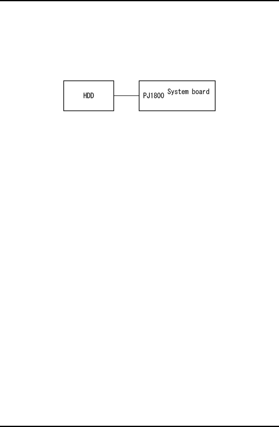
2 Troubleshooting Procedures 2.6 HDD Troubleshooting
Procedure 5 Connector Check and Replacement Check
The HDD may be disconnected, or the HDD or the system board may be damaged.
Disassemble the computer following the steps described in Chapter 4, Replacement
Procedures and perform the following checks:
Check 1 Make sure the HDD is firmly connected to the system board.
If the connection is loose, reconnect firmly and repeat Procedure 1. If there is still
an error, go to Check 2.
Check 2 The HDD may be damaged. Replace it with a new one following the instructions
in Chapter 4, Replacement Procedures. If the problem still exists, perform Check
3.
Check 3 The system board may be damaged. Replace it with a new one following the
instructions in Chapter 4, Replacement Procedures.
2-38 Satellite M30-35 Maintenance Manual (960-455)

2.7 Keyboard Troubleshooting 2 Troubleshooting Procedures
2.7 Keyboard Troubleshooting
To determine if the computer’s keyboard is functioning properly, perform the following
procedures. Start with Procedure 1 and continue with the other procedures as instructed.
Procedure 1: Diagnostic Test Program Execution Check
Procedure 2: Connector and Replacement Check
Procedure 1 Diagnostic Test Program Execution Check
Execute the Keyboard Test in the Diagnostic Program. Refer to Chapter 3, Tests and
Diagnostics, for more information on how to perform the test program.
If an error occurs, go to Procedure 2. If an error does not occur, the keyboard is functioning
properly.
Satellite M30-35 Maintenance Manual (960-455) 2-39
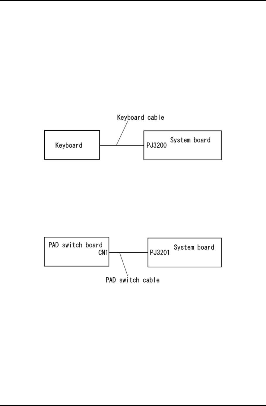
2 Troubleshooting Procedures 2.7 Keyboard Troubleshooting
Procedure 2 Connector and Replacement Check
The keyboard, PAD I/F and PAD Switch may be disconnected or damaged. Disassemble the
computer following the steps described in Chapter 4, Replacement Procedures, and perform
the following checks:
1. If the keyboard malfunctions, start with Check 1.
2. If the PAD switch malfunctions, start with Check 3.
Check 1 Make sure the keyboard cable is securely connected to the system board.
If the connection is loose, reconnect firmly and repeat Procedure 1. If there is still
an error, go to Check 2.
Check 2 The keyboard or its cable may be damaged. Replace it with a new one following
the instructions in Chapter 4, Replacement Procedures. If the problem still exists,
perform Check 5.
Check 3 Make sure the PAD switch cable is firmly connected to the system board.
If the connection is loose, reconnect firmly and repeat Procedure 2. If there is still
an error, go to Check 4.
Check 4 The PAD switch board or PAD switch cable may be damaged. Replace it with a
new one following the instructions in Chapter 4, Replacement Procedures. If the
problem still exists, perform Check 5.
Check 5 The system board may be damaged. Replace it with a new one following the
instructions in Chapter 4, Replacement Procedures.
2-40 Satellite M30-35 Maintenance Manual (960-455)

2.8 Display Troubleshooting 2 Troubleshooting Procedures
2.8 Display Troubleshooting
This section describes how to determine if the computer’s display is functioning properly.
Start with Procedure 1 and continue with the other procedures as instructed.
Procedure 1: External Monitor Check
Procedure 2: Diagnostic Test Program Execution Check
Procedure 3: Connector and Cable Check
Procedure 4: Replacement Check
Procedure 1 External Monitor Check
Connect an external monitor to the computer’s external monitor port, then boot the computer.
The computer automatically detects the external monitor.
If the external monitor works correctly, the internal LCD may be damaged. Go to Procedure
3.
If the external monitor appears to have the same problem as the internal monitor, the system
board may be damaged. Go to Procedure 2.
Procedure 2 Diagnostic Test Program Execution Check
The Display Test program is stored on the computer’s Diagnostics disk. This program checks
the display controller on the system board. Insert the Diagnostics disk in the computer’s
floppy disk drive, turn on the computer and run the test. Refer to Chapter 3, Tests and
Diagnostics for details. If an error is detected, go to Procedure 3.
Satellite M30-35 Maintenance Manual (960-455) 2-41
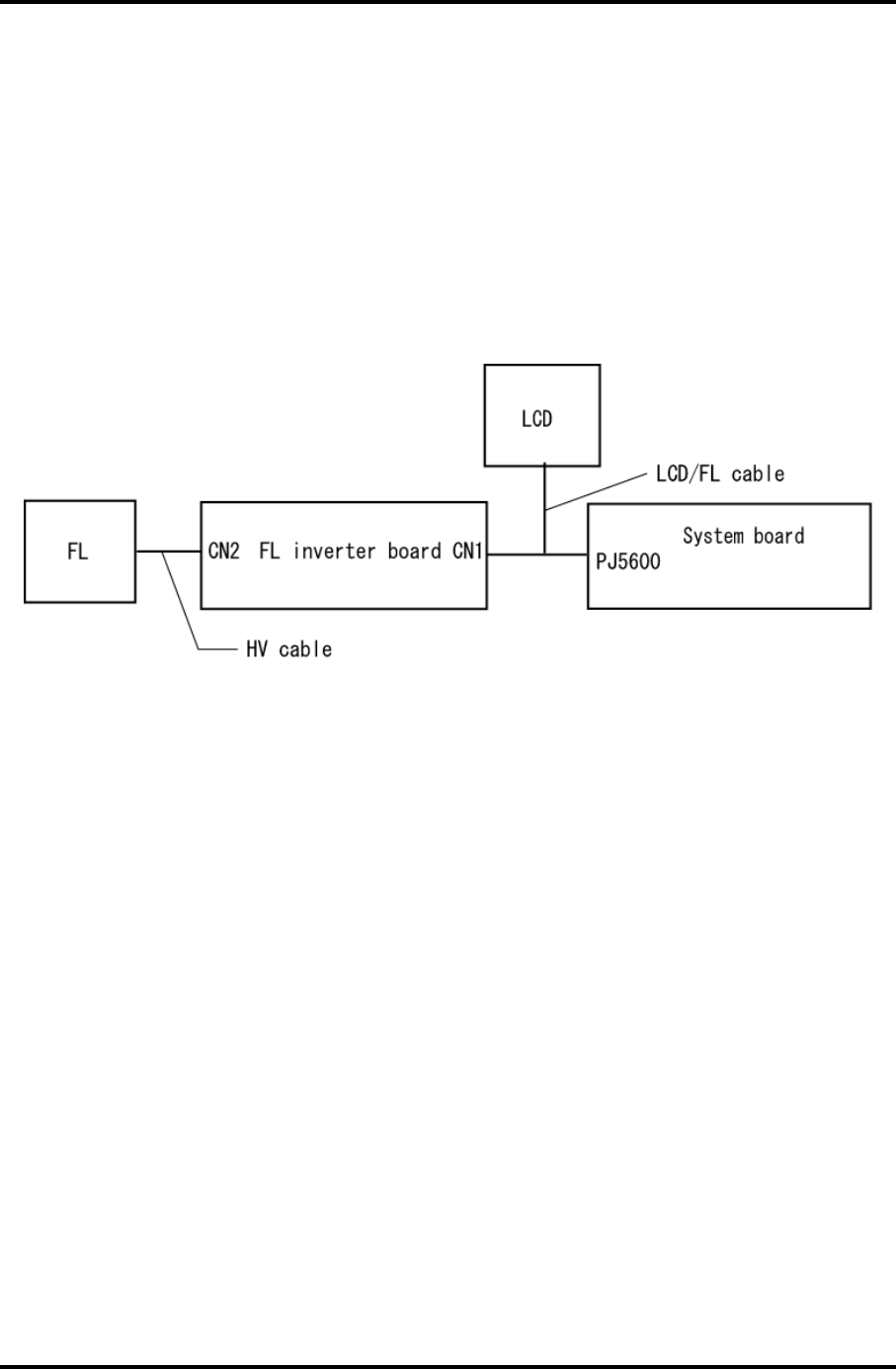
2 Troubleshooting Procedures 2.8 Display Troubleshooting
Procedure 3 Connector and Cable Check
The LCD Module is connected to the system board by an LCD/FL cable. The FL inverter
board is also connected to the system board by an LCD/FL cable. And the FL is connected to
the FL inverter board by the HV cable. The connectors may be disconnected from the system
board or the FL inverter board, or they may be damaged. Disassemble the computer
following the steps described in Chapter 4, Replacement Procedures.
If the connection is loose, reconnect firmly and restart the computer. If there is still an error,
go to Procedure 4.
2-42 Satellite M30-35 Maintenance Manual (960-455)

2.8 Display Troubleshooting 2 Troubleshooting Procedures
Procedure 4 Replacement Check
The FL, FL inverter board, LCD module, and system board are connected to display circuits.
Any of these components may be damaged. Refer to Chapter 4, Replacement Procedures, for
instructions on how to disassemble the computer and then perform the following checks:
If the FL does not light, perform Check 1.
If characters or graphics are not displayed clearly, perform Check 4.
If some screen functions do not operate properly, perform Check 4.
If the FL remains lit when the display is closed, perform Check 5.
Check 1 Replace the FL with a new one following the instructions in Chapter 4,
Replacement Procedures and test the display again. If the problem still exists,
perform Check2.
Check 2 The LCD/FL cable or HV cable may be defective or damaged. Replace the
FL/LCD or HV cable with a new one following the instructions in Chapter 4,
Replacement Procedure and test the display again. If the problem still exists,
perform Check3.
Check 3 The FL inverter board may be defective or damaged. Replace the FL inverter
board with a new one following the instructions in Chapter 4, Replacement
Procedure and test the display again. If the problem still exists, perform Check4.
Check 4 The LCD module may be defective or damaged. Replace the LCD module with a
new one following the instructions in Chapter 4, Replacement Procedure and test
the display again. If the problem still exists, perform Check 5.
Check 5 The system board may be defective or damaged. Replace it with a new one
following the instructions in Chapter 4, Replacement Procedure.
Satellite M30-35 Maintenance Manual (960-455) 2-43

2 Troubleshooting Procedures 2.9 Optical Drive Troubleshooting
2.9 Optical Drive Troubleshooting
This section describes how to determine if the Optical Drive is functioning properly. Perform
the steps below starting with Procedure 1 and continue with the other procedures as required.
Procedure 1: Diagnostic Test Program Execution Check
Procedure 2: Connector Check and Replacement Check
Procedure 1 Diagnostic Test Program Execution Check
The CD-ROM/DVD-ROM test program is stored in the Diagnostics Disk.
For the test, prepare a test CD-ROM, DVD-ROM, music CD and CD-RW Media.
Then insert the Diagnostics Disk in the computer’s floppy disk drive, turn on the computer
and run the test. Refer to Chapter 3, Tests and Diagnostics, for more information about the
diagnostics test procedures.
If any errors occur while executing the CD-ROM/DVD-ROM test, go to Procedure 2.
2-44 Satellite M30-35 Maintenance Manual (960-455)
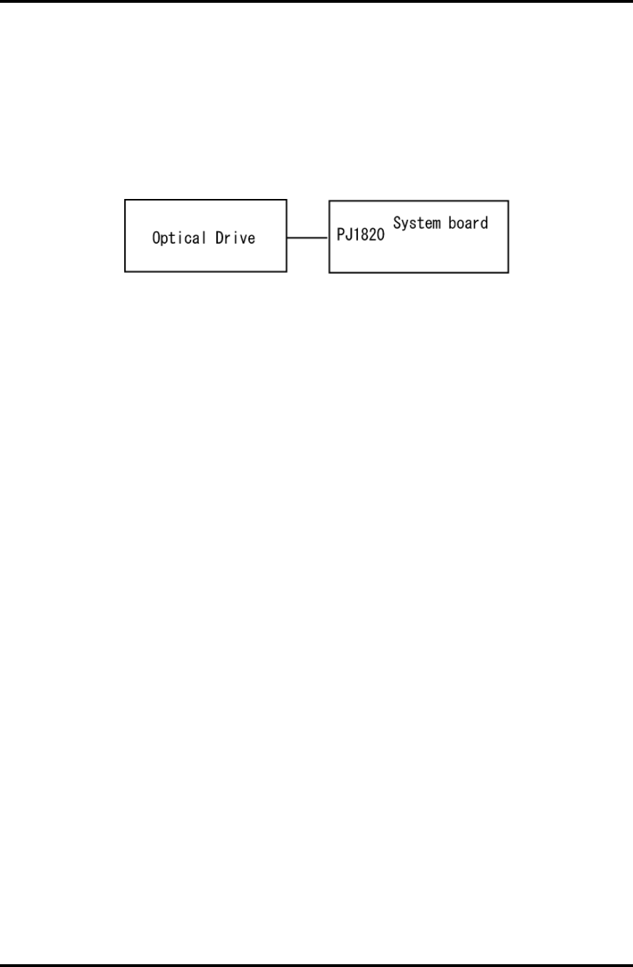
2.9 Optical Drive Troubleshooting 2 Troubleshooting Procedures
Procedure 2 Connector Check and Replacement Check
The Optical Drive is connected to the system board. The connectors may be disconnected
from the system board or may be damaged. Disassemble the computer following the steps
described in Chapter 4, Replacement Procedures and perform the following checks:
Check 1 Make sure the Optical Drive is firmly connected to the system board.
If the connection is loose, reconnect firmly and repeat Procedure 1. If there is still
an error, go to Check 2.
Check 2 The Optical Drive may be defective or damaged. Replace the drive with a new
one. If there is still an error, go to Check 3.
Check 3 Replace the system board with a new one following the steps in Chapter 4,
Replacement Procedures.
Satellite M30-35 Maintenance Manual (960-455) 2-45

2 Troubleshooting Procedures 2.10 Modem Troubleshooting
2.10 Modem Troubleshooting
This section describes how to determine if the computer's modem is functioning properly.
Perform the steps below starting with Procedure 1 and continuing with the other procedures
as required.
Procedure 1: Diagnostic Test Program Execution Check
Procedure 2: Connector Check and Replacement Check
Procedure 1 Diagnostic Test Program Execution Check
The Sound/LAN/Modem test program is stored in the Diagnostics Disk.
For the test, prepare a test Sound/LAN/Modem.
Then insert the Diagnostics Disk in the computer’s floppy disk drive, turn on the computer
and run the test. Refer to Chapter 3, Tests and Diagnostics, for more information about the
diagnostics test procedures.
If any errors occur while executing the Sound/LAN/Modem test, go to Procedure 2.
2-46 Satellite M30-35 Maintenance Manual (960-455)
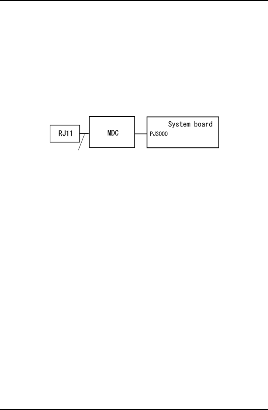
2.10 Modem Troubleshooting 2 Troubleshooting Procedures
Procedure 2 Connector Check and Replacement Check
The Modem is installed as a modem daughter card (MDC). If the modem malfunctions, there
may be a bad connection between the MDC and the System Board. Or the MDC, System
Board or their connectors might be damaged.
Disassemble the computer following the steps described in Chapter 4, Replacement
Procedures and perform the following checks:
Check 1 Make sure the MDC cable is firmly connected to the MDC and make sure the
MDC is firmly connected to PJ3000 on the System Board.
MDC cable
If a connector is disconnected, connect it firmly and repeat Procedure 1. If the
Modem is still not functioning properly, perform Check 2.
Check 2 The MDC may be defective or damaged. Replace it with a new one following the
steps in Chapter 4, Replacement Procedures. If the Modem is still not functioning
properly, perform Check 3.
Check 3 The system board may be defective or damaged. Replace the System Board with a
new one following the steps in Chapter 4, Replacement Procedures.
Satellite M30-35 Maintenance Manual (960-455) 2-47
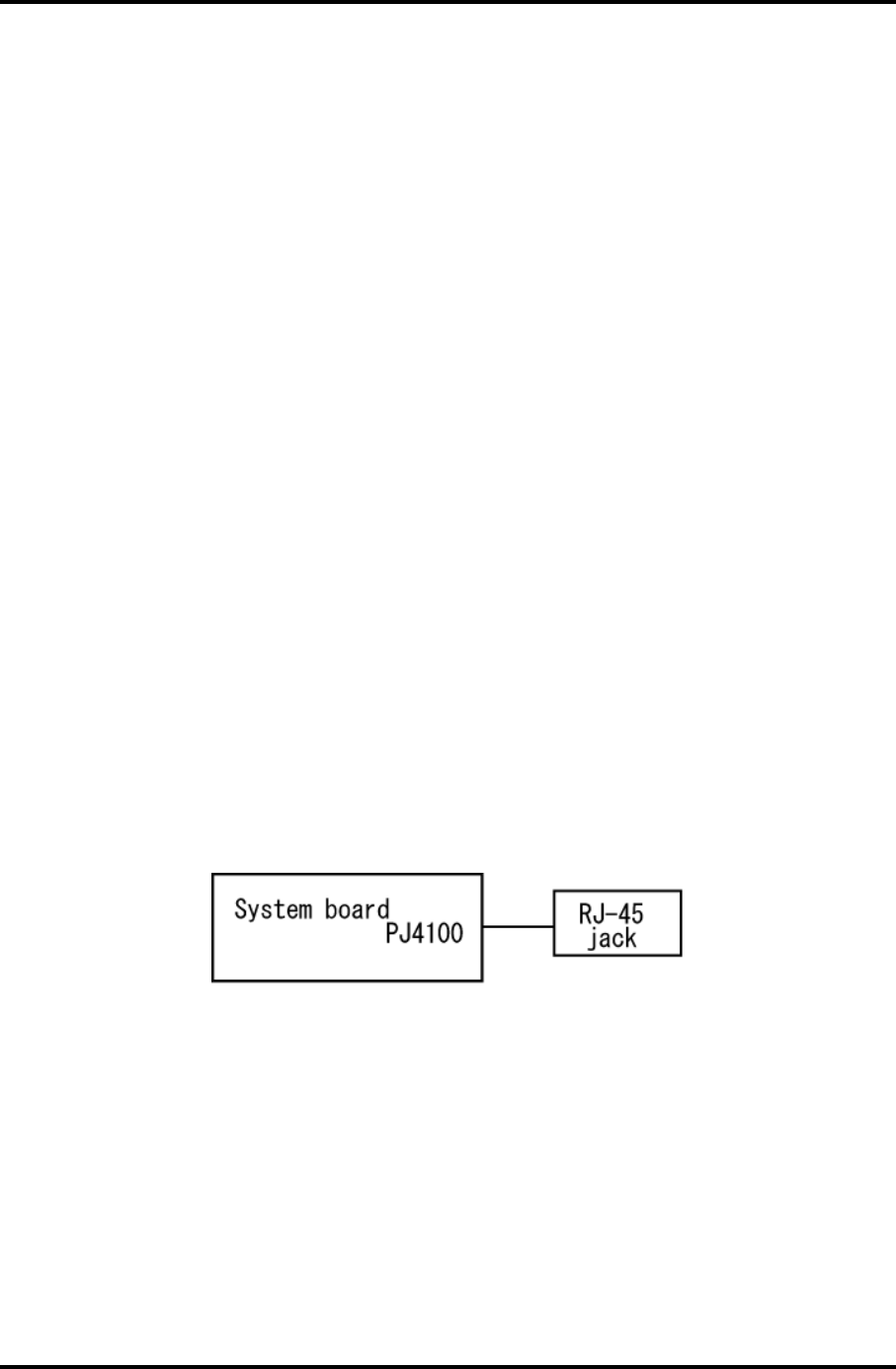
2 Troubleshooting Procedures 2.12 LAN Troubleshooting
2.11 LAN Troubleshooting
This section describes how to determine if the computer's LAN is functioning properly.
Perform the steps below starting with Procedure 1 and continuing with the other procedures
as required.
Procedure 1: Diagnostic Test Program Execution Check
Procedure 2: Connector Check and Replacement Check
Procedure 1 Diagnostic Test Program Execution Check
The Sound/LAN/Modem test program is stored in the Diagnostics Disk.
For the test, prepare a test Sound/LAN/Modem.
Then insert the Diagnostics Disk in the computer’s floppy disk drive, turn on the computer
and run the test. Refer to Chapter 3, Tests and Diagnostics, for more information about the
diagnostics test procedures.
If any errors occur while executing the Sound/LAN/Modem test, go to Procedure 2.
Procedure 2 Connector Check and Replacement Check
A RJ45 jack with LAN cable is on the System Board. If the LAN malfunctions, the System
Board might be damaged.
Disassemble the computer following the steps described in Chapter 4, Replacement
Procedures.
2-48 Satellite M30-35 Maintenance Manual (960-455)

2.12 Wireless LAN Troubleshooting 2 Troubleshooting Procedures
2.12 Wireless LAN Troubleshooting
This section describes how to determine if the computer's Wireless LAN is functioning
properly. Perform the steps below starting with Procedure 1 and continuing with the other
procedures as required.
Procedure 1: Transmitting-Receiving Check
Procedure 2: Antennas' Connection Check
Procedure 3: Antennas' Capability Check
Procedure 4: Replacement Check
Procedure 1 Transmitting-Receiving Check
Make sure the wireless communication switch on the front side of the computer is turned ON.
If it is not, slide the switch toward the back of the computer to turn it on.
Check 1 Execute test program to check the transmitting-receiving function of the wireless
LAN. You will need a second computer that can communicate by the wireless
LAN. Perform the test following the instructions described in Chapter 3, Wireless
LAN Test Program.
If the computer passes the test, the function is correctly working.
If the computer does not pass the test, perform Procedure 2.
Satellite M30-35 Maintenance Manual (960-455) 2-49
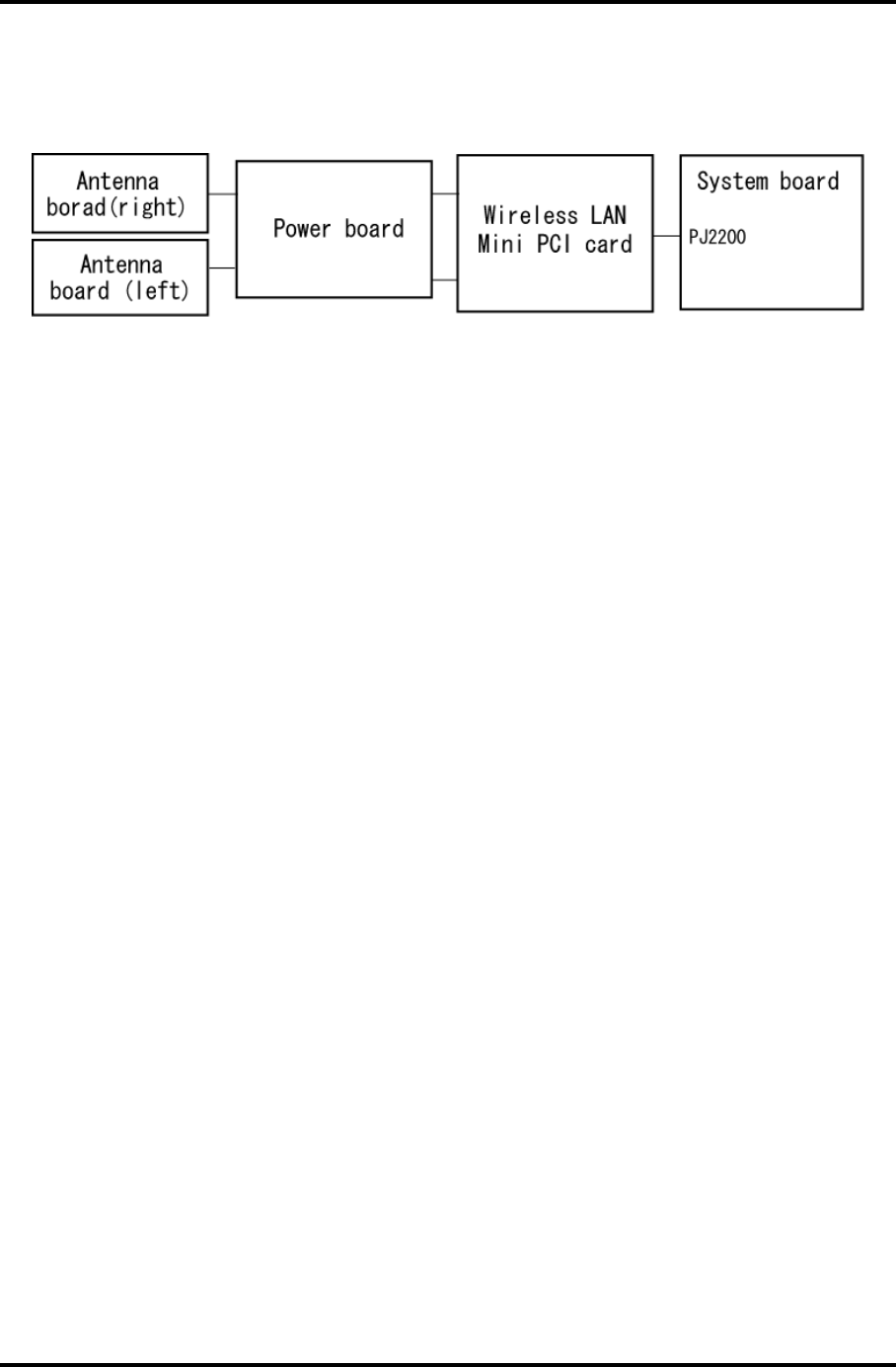
2 Troubleshooting Procedures 2.12 Wireless LAN Troubleshooting
Procedure 2 Antennas' Connection Check
The wireless LAN wiring diagram is shown below:
Any of the connections may be disconnected. Disassemble the computer following the steps
described in Chapter 4, Replacement Procedures, and perform the following checks:
Check 1 Make sure the wireless communication switch is “On”.
If the switch is “Off”, turn it “On”. If the wireless LAN is still not functioning
properly, perform Check 2.
Check 2 Make sure the wireless LAN board is firmly connected to PJ2200 on the system
board.
If the connector is disconnected, connect it firmly and perform Procedure 1. If the
wireless LAN board is still not functioning properly, perform Check 3.
Check 3 Make sure the wireless LAN antenna cables (black and white) are firmly
connected to the Wireless LAN card.
If the wireless LAN antenna cables are disconnected, connect them firmly and
perform Procedure 1. If the wireless LAN function is still not functioning
properly, perform Check 3.
Check 4 Make sure the wireless LAN antenna cables (black and white) are firmly
connected from the power board to the Wireless LAN card.
If the wireless LAN antenna cables are disconnected, connect them firmly and
perform Procedure 1. If the wireless LAN function is still not functioning
properly, perform Procedure 3.
2-50 Satellite M30-35 Maintenance Manual (960-455)
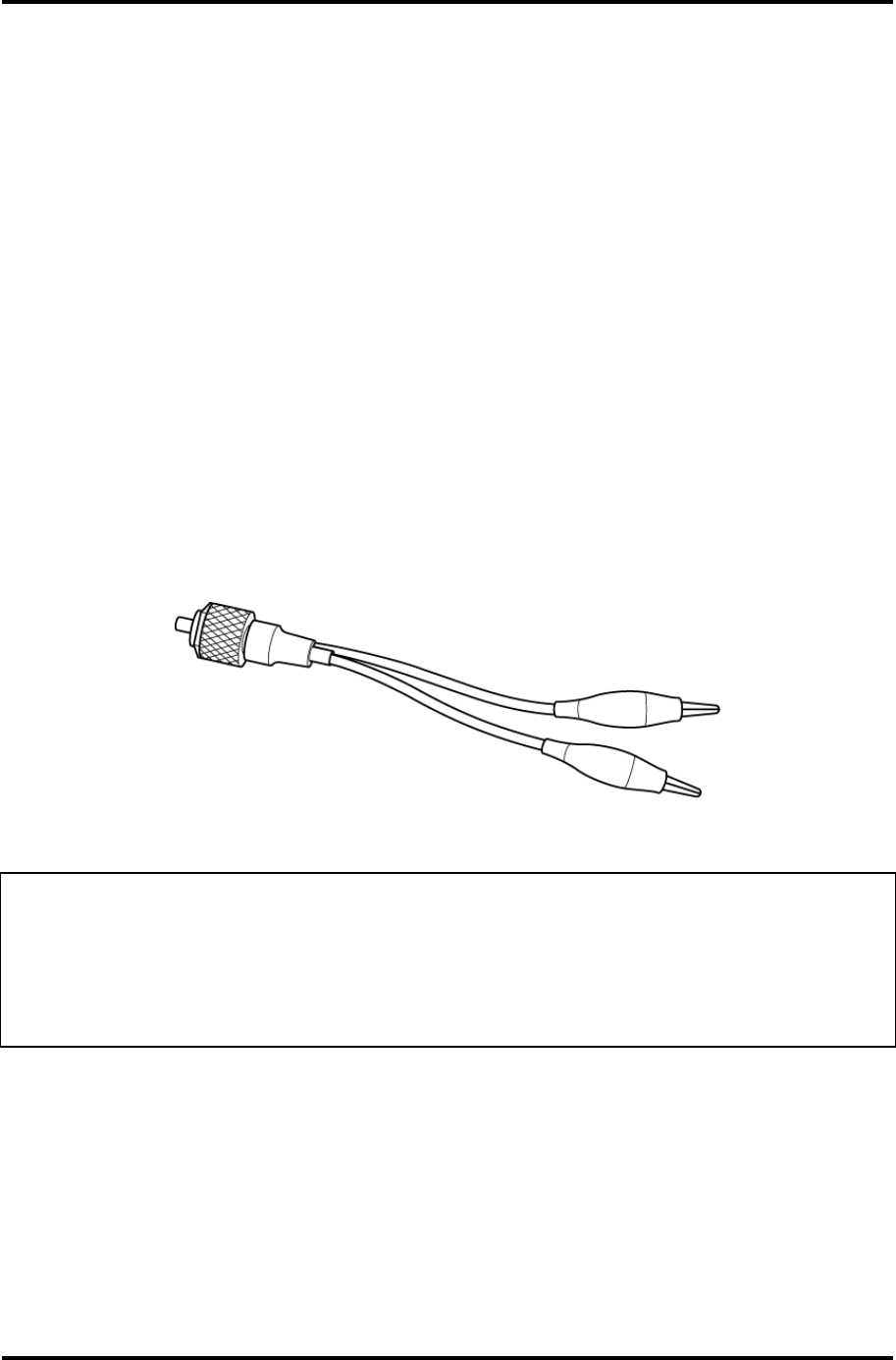
2.12 Wireless LAN Troubleshooting 2 Troubleshooting Procedures
Procedure 3 Antenna Check
Check 1 Use an antenna test cable to check the antennas' connection. Follow the steps
below:
1. Remove the wireless LAN slot cover and lift it off. Refer to Chapter 4,
Replacement Procedures, for detailed steps of disassembling.
2. Disconnect the wireless LAN antenna cables connected to the wireless LAN
board.
3. Connect the end of the antenna test cable to the multimeter.
4. Connect the Main antenna cable to the antenna test cable. One clip is
connected to the end of the white antenna cable. The other is connected to the
opposite side of the antenna cable.
5. Determine the resistance. The cable passes the test when the resistance is 5Ω.
Or less. If it is more than 5Ω, the antenna cable fails the test.
6. Change the antenna cable. Perform from step 3 to check the black antenna
cable.
Figure 2-3 Antenna Test cable
NOTE: 1. The resistances determined with the steps above may not be stable with
other machines because of "cable loss," which varies according to the
length of the cable. The impedance of the antenna itself is about 0.5-0.8
Ω
.
2. The above steps cannot accurately determine the impedance of the antenna.
Use an LC meter for a precise measure of impedance.
If the wireless LAN antenna cables pass the test, connect them to the wireless LAN board
and cover the slot, then perform Procedure 1.
If the wireless LAN antenna cables do not pass the test, replace the wireless LAN antenna
cables with new ones following the steps in Chapter 4, Replacement Procedures. If the
wireless LAN is still not functioning properly, go to Procedure 4.
Satellite M30-35 Maintenance Manual (960-455) 2-51

2 Troubleshooting Procedures 2.12 Wireless LAN Troubleshooting
Procedure 4 Replacement Check
The wireless LAN board is connected to the power board and the system board. Any of these
components may be damaged. Refer to Chapter 4, Replacement Procedures, for instructions
on how to disassemble the computer and then perform the following checks:
Check 1 Replace the wireless LAN board with a new one following the instructions in
Chapter 4, Replacement Procedures and test the display again. If the problem still
exists, perform Check2.
Check 2 The power board may be defective or damaged. Replace it with a new one
following the steps in Chapter 4, Replacement Procedures. If the problem still
exists, perform Check3.
Check 3 Replace the system board with a new one following the instructions in Chapter 4,
Replacement Procedures.
2-52 Satellite M30-35 Maintenance Manual (960-455)

2.13 Sound Troubleshooting 2 Troubleshooting Procedures
2.13 Sound Troubleshooting
This section describes how to determine if the computer's sound functions are functioning
properly. Perform the steps below starting with Procedure 1 and continuing with the other
procedures as required.
Procedure 1: Diagnostic Test Program Execution Check
Procedure 2: Connector Check
Procedure 3: Replacement Check
Procedure 1 Diagnostic Test Program Execution Check
The Sound/LAN/Modem test program is stored on the computer’s diagnostic disk. Insert the
Diagnostics disk in the computer's floppy disk drive, turn on the computer and run the test.
Refer to Chapter 3, Tests and Diagnostics, for details.
If an error is detected, go to Procedure 2.
Satellite M30-35 Maintenance Manual (960-455) 2-53
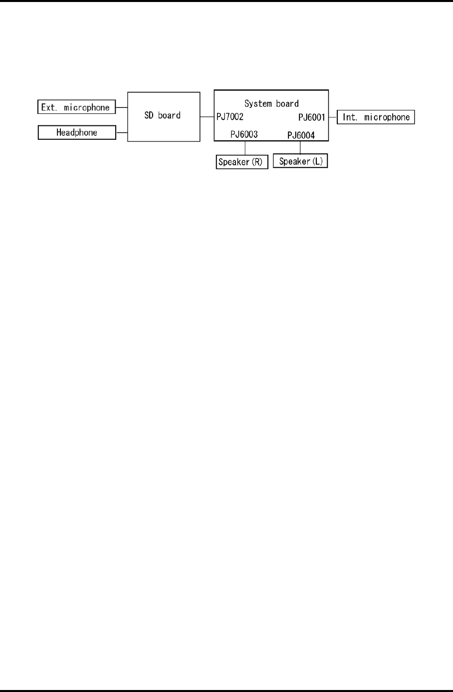
2 Troubleshooting Procedures 2.13 Sound Troubleshooting
Procedure 2 Connector Check
The sound function wiring diagram is shown below:
Any of the connections may be disconnected. Disassemble the computer following the steps
described in Chapter 4, Replacement Procedures and perform the following checks:
If the stereo speakers do not work correctly, perform Check 1.
If headphones do not work correctly, perform Check 2.
If sound recording does not work correctly, perform Check 3.
Check 1 If the stereo speakers do not work properly, the speaker cables may be
disconnected. Make sure the speaker cables are firmly connected to PJ6003 or
PJ6004 on the system board. If the stereo speakers are still not functioning
properly, go to Procedure 3.
Check 2 If headphones do not work properly, the SD board may be disconnected or
damaged. Make sure the connector on the SD board is firmly connected to PJ7002
on the system board. If the sound function still does not work properly, replace it
with a new one. Go to Procedure 3.
Check 3 If the sound recording function does not work properly, the internal microphone
cable or external microphone cable may be disconnected. Make sure the internal
microphone cable is firmly connected to PJ6001 on the system board and the SD
card is firmly connected to PJ7002 on the system board. If recording is still not
functioning properly, go to Procedure 3.
2-54 Satellite M30-35 Maintenance Manual (960-455)

2.13 Sound Troubleshooting 2 Troubleshooting Procedures
Procedure 3 Replacement Check
Check 1 If the stereo speakers do not sound properly, they may be defective or damaged.
Replace them with new ones. If the stereo speakers still do not work properly, go
to Check 5.
Check 2 If headphones does sound properly, the headphone jack may be defective or
damaged. Replace the SD board with a new one. If the headphone still does not
work properly, go to Check 5.
Check 3 If the recording function does not work properly by the external microphone, the
external microphone jack may be defective or damaged. Replace the SD board
with a new one. If the recording function still does not work properly, go to Check
5.
Check 4 If the recording function does not work properly by the internal microphone, the
internal microphone may be defective or damaged. Replace it with a new one. If
the recording function still does not work properly, go to Check 5.
Check 5 The system board may be defective or damaged. Replace the system board with a
new one following the instructions in Chapter 4, Replacement Procedures.
Satellite M30-35 Maintenance Manual (960-455) 2-55
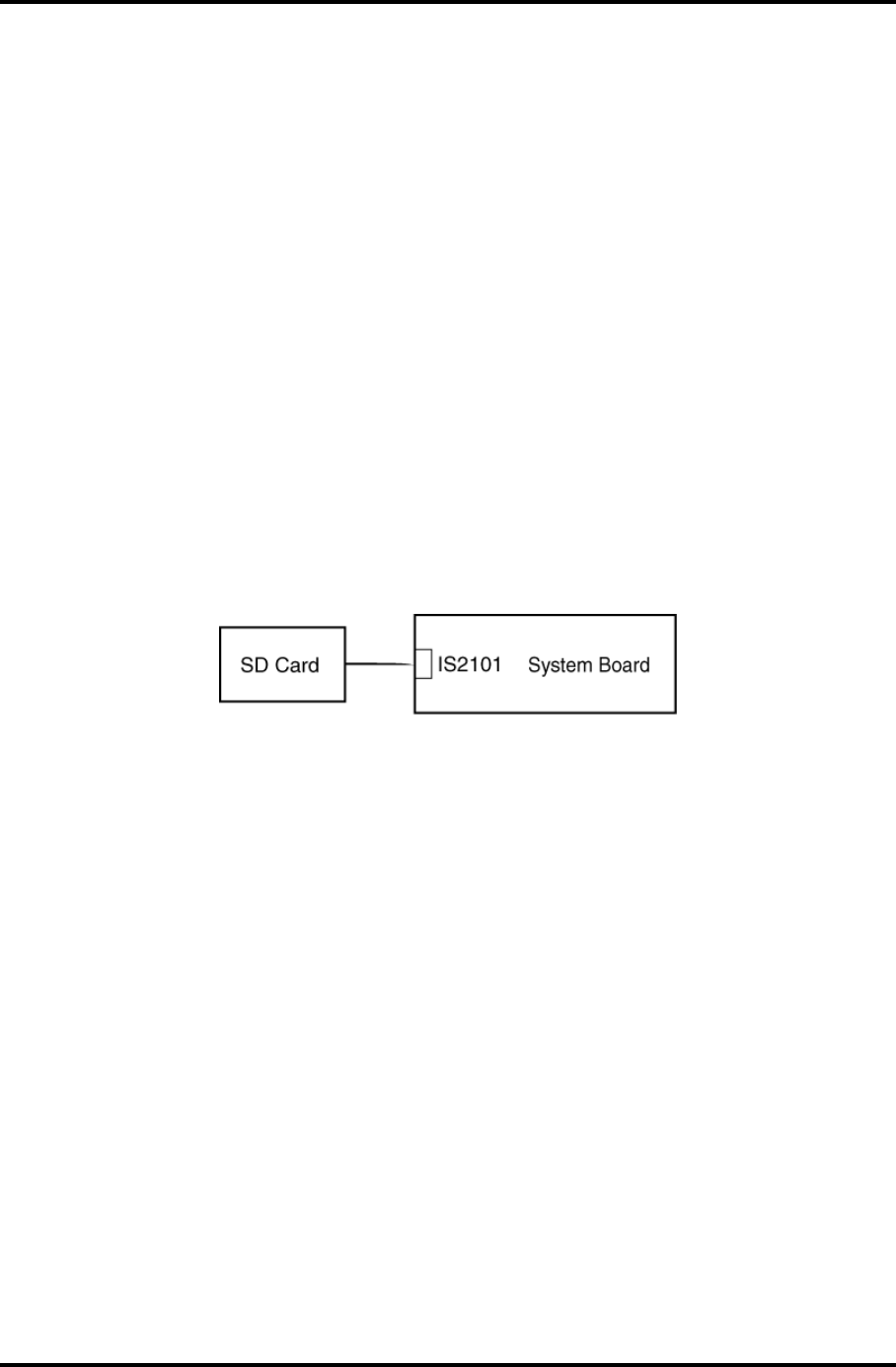
2 Troubleshooting Procedures 2.14 SD Card Slot Troubleshooting
2.14 SD Card Slot Troubleshooting
To check if the SD card/Smart Media slot is good or no good, follow the troubleshooting
procedures below as instructed.
Procedure 1: Check on Windows
Procedure 2: Connector/Replacement Check
Procedure 1 Check on Windows
Insert an SD card into the slot. Check if Windows recognizes automatically the SD card and
the data in the SD card can be read.
If the card is not recognized or data are not red, go to Procedure 2.
Procedure 2 Connector/Replacement Check
The SD card is connected to IS2101 on the system board.
Check 1 The SD card and the system board may be disconnected. Make sure the SD card is
firmly inserted to IS2101 on the system board. If not, insert it firmly. If the SD
card is still not functioning properly, perform Check 2.
Check 2 The SD card may be faulty. Replace it with a new one following the step in
Chapter 4. If the problem continues, perform Check 3.
Check 3 The system board may be faulty. Replace it with a new one following the step in
Chapter 4.
2-56 Satellite M30-35 Maintenance Manual (960-455)

2.14 SD Card Slot Troubleshooting 2 Troubleshooting Procedures
Satellite M30-35 Maintenance Manual (960-455) 2-57

Chapter 3
Tests and Diagnostics

3 Tests and Diagnostics
3-ii Satellite M30-35 Maintenance Manual (960-455)

3 Tests and Diagnostics
Chapter 3 Contents
3.1 The Diagnostic Test ................................................................................................... 3-1
3.2 Executing the Diagnostic Test ................................................................................... 3-3
3.3 Subtest Names............................................................................................................ 3-7
3.4 System Test................................................................................................................ 3-9
3.5 Memory Test............................................................................................................ 3-12
3.6 Keyboard Test.......................................................................................................... 3-13
3.7 Display Test ............................................................................................................. 3-16
3.8 Floppy Disk Test...................................................................................................... 3-19
3.9 Printer Test............................................................................................................... 3-21
3.10 Async Test ............................................................................................................... 3-23
3.11 Hard Disk Test ......................................................................................................... 3-24
3.12 Real Timer Test........................................................................................................ 3-27
3.13 NDP Test.................................................................................................................. 3-29
3.14 Expansion Test......................................................................................................... 3-30
3.15 CD-ROM/DVD-ROM Test ..................................................................................... 3-31
3.16 LAN Test ................................................................................................................. 3-32
3.17 Error Code and Error Status Names ........................................................................ 3-33
3.18 Hard Disk Test Detail Status ................................................................................... 3-36
3.19 Head Cleaning.......................................................................................................... 3-38
3.19.1 Function Description .......................................................................... 3-38
3.19.2 Operations .......................................................................................... 3-38
3.20 Log Utilities ............................................................................................................. 3-39
3.20.1 Function Description .......................................................................... 3-39
3.20.2 Operations .......................................................................................... 3-40
3.21 Running Test............................................................................................................ 3-41
3.21.1 Function Description .......................................................................... 3-41
3.21.2 Operations .......................................................................................... 3-41
3.22 Floppy Disk Drive Utilities...................................................................................... 3-42
3.22.1 Function Description .......................................................................... 3-42
3.22.2 Operations .......................................................................................... 3-43
Satellite M30-35 Maintenance Manual (960-455) 3-iii

3 Tests and Diagnostics
3-iv Satellite M30-35 Maintenance Manual (960-455)
3.23 System Configuration .............................................................................................. 3-47
3.23.1 Function Description .......................................................................... 3-47
3.23.2 Operations .......................................................................................... 3-48
3.24 Wireless LAN Test Program (Calexico).................................................................. 3-49
3.25 Wireless LAN Test Program (Atheros 11b/g or 11a/b/g)........................................ 3-50
3.26 Sound/LAN/Modem Test Program.......................................................................... 3-53
3.27 IEEE1394 Test Program .......................................................................................... 3-57
Tables
Table 3-1 Subtest names................................................................................................. 3-7
Table 3-2 Error codes and error status names .............................................................. 3-33
Table 3-3 Hard disk controller status register contents................................................ 3-36
Table 3-4 Error register contents.................................................................................. 3-37

3.1 The Diagnostic Test 3 Tests and Diagnostics
3
3.1 The Diagnostic Test
This chapter explains how to use the Diagnostic Test program to test the functions of the
computer’s hardware modules. The Diagnostic Test Program is stored on the Diagnostic
Disk. The Diagnostic Test program consists of eight programs that are grouped into the
Service Program Module (DIAGNOSTIC TEST MENU).
NOTES: To start the diagnostics, follow these steps:
1. Check all cables for loose connections.
2. Exit any application you may be using and close Windows.
The DIAGNOSTIC MENU consists of the following six functions.
DIAGNOSTIC TEST
HEAD CLEANING
LOG UTILITIES
RUNNING TEST
FDD UTILITIES
SYSTEM CONFIGURATION
EXIT TO MS-DOS
The DIAGNOSTIC TEST MENU contains the following thirteen functional tests:
SYSTEM TEST
MEMORY TEST
KEYBOARD TEST
DISPLAY TEST
FLOPPY DISK TEST
PRINTER TEST
ASYNC TEST
HARD DISK TEST
REAL TIMER TEST
NDP TEST
EXPANSION TEST
CD-ROM/DVD TEST
LAN TEST
Satellite M30-35 Maintenance Manual (960-455) 3-1

3 Tests and Diagnostics 3.1 The Diagnostic Test
You will need the following equipment to perform some of the Diagnostic test programs.
The Diagnostics Disk (all tests)
A formatted working disk for the floppy disk drive test
An external FDD attachment
A cleaning kit to clean the floppy disk drive heads (Head Cleaning)
A cleaning kit to clean the DVD-ROM drive heads (Head Cleaning)
A PC card wraparound connector for the I/O card test (Expansion test)
A printer wraparound connector for the printer wraparound test (Printer test)
A CD test media (TOSHIBA CD-ROM TEST DISK (ZA1217P01/P000204190) and
music CD) (CD-ROM test)
A DVD test media (Toshiba-EMI DVD-ROM TEST DISK TSD-1)
External CRT (Display test)
PS/2 or compatible keyboard (Keyboard test)
PS/2 or compatible mouse (Keyboard test)
Headphone (Sound test)
CD-ROM drive (CD-ROM test)
A microphone
A modular cable and RJ11 connector checker
A modular cable and RJ11 connector checker (LED)
USB test module and USB cable
LAN wraparound connector
Music CD (CD-ROM/DVD-ROM test)
The following sections detail the tests within the Diagnostic Test function of the
DIAGNOSTIC TEST MENU. Refer to Sections 3.17 through 3.27 for detailed information
on the remaining Service Program Module functions.
3-2 Satellite M30-35 Maintenance Manual (960-455)
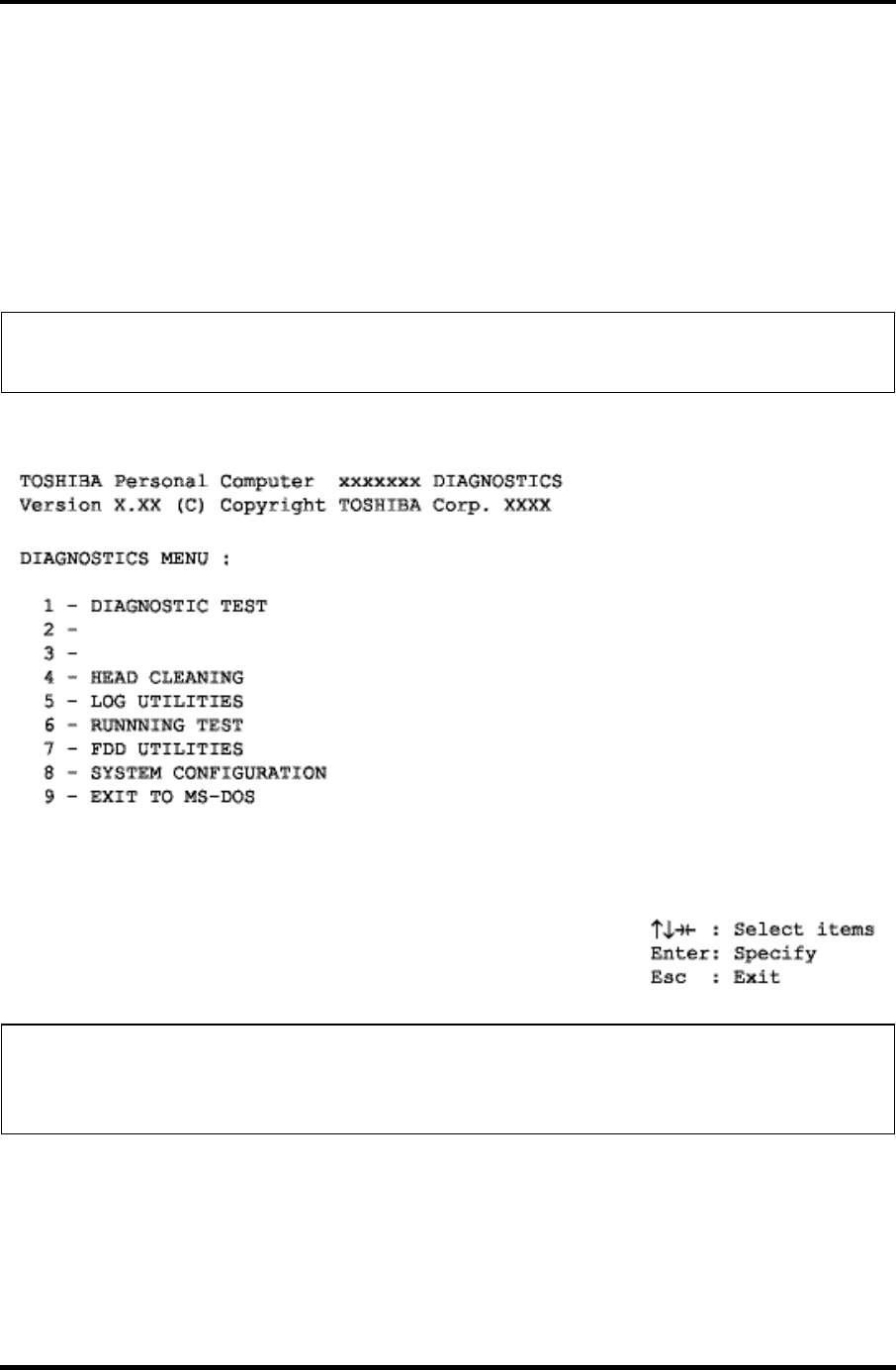
3.2 Executing the Diagnostic Test 3 Tests and Diagnostics
3.2 Executing the Diagnostic Test
Toshiba MS-DOS is required to run the DIAGNOSTICS TEST PROGRAM. To start the
DIAGNOSTIC TEST PROGRAM, follow these steps:
1. Insert the Diagnostics disk in the floppy disk drive and turn on the computer while
pressing F key.
(The Diagnostics Disk contains the MS-DOS boot files.)
NOTE: To execute the CD-ROM or DVD-ROM test, make sure the CD-ROM and CD-
ROM drive or DVD-ROM and DVD-ROM drive is installed in the computer.
The following menu will appear:
NOTE: To exit the DIAGNOSTIC TEST MENU, press the Esc key. If a test program is
in progress, press Ctrl + Break to exit the test program, or press Ctrl + C to
stop the test program.
Satellite M30-35 Maintenance Manual (960-455) 3-3

3 Tests and Diagnostics 3.2 Executing the Diagnostic Test
2. To execute the DIAGNOSTIC TEST MENU from the DIAGNOSTICS MENU, set
the highlight bar to 1, and press Enter. The following DIAGNOSTIC TEST MENU
will appear:
TOSHIBA Personal Computer XXXXXX DIAGNOSTICS
Version X.XX (C) Copyright TOSHIBA Corp. XXXX
DIAGNOSTIC TEST MENU :
1 - SYSTEM TEST
2 - MEMORY TEST
3 - KEYBOARD TEST
4 - DISPLAY TEST
5 - FLOPPY DISK TEST
6 - PRINTER TEST
7 – ASYNC TEST
8 - HARD DISK TEST
9 - REAL TIMER TEST
10 - NDP TEST
11 - EXPANSION TEST
12 -
13 – CD-ROM/DVD-ROM TEST
14 – LAN TEST
88 - ERROR RETRY COUNT SET [FDD & HDD]
99 - EXIT TO DIAGNOSTICS MENU
↑↓→← : Select items
Enter : Specify
Esc : Exit
Refer to sections 3.4 through 3.16 for detailed descriptions of each Diagnostic Tests 1
through 14. Function 88 sets the floppy disk drive and hard disk drive error retry
count (0-255). To return to the Diagnostics Menu, set the highlight bar to Function 99
and press Enter.
3-4 Satellite M30-35 Maintenance Manual (960-455)
3.2 Executing the Diagnostic Test 3 Tests and Diagnostics
3. Select the test you want to execute and press Enter. When SYSTEM TEST is
selected, the following message will appear:
SYSTEM TEST XXXXXXX XXX DIAGNOSTIC TEST VX.XX
[Ctrl]+[Break] : test end
[Ctrl]+[C] : key stop
SUB-TEST : XX
PASS COUNT : XXXXX ERROR COUNT : XXXXX
WRITE DATA : XX READ DATA : XX
ADDRESS : XXXXXX STATUS : XXX
SUB-TEST MENU :
01 - ROM checksum
02 –
03 -
04 - Fan ON/OFF
05 – Geyserville
06 - Quick charge
07 - DMI read
08 - DMI write
09 -
10 – CPU Temperature
99 - Exit to DIAGNOSTIC TEST MENU
↑↓→← : Select items
Enter : Specify
Esc : Exit
NOTE: The menu displayed by your computer may be slightly different from the one
shown above.
4. Select the desired subtest number from the subtest menu and press Enter. The
following message will appear:
TEST LOOP : YES/NO
Selecting YES increases the pass counter by one, each time the test cycle ends and
restarts the test cycle.
Selecting NO returns to the subtest menu after the test is complete.
Satellite M30-35 Maintenance Manual (960-455) 3-5

3 Tests and Diagnostics 3.2 Executing the Diagnostic Test
5. The following message will appear:
ERROR STOP : YES/NO
Selecting YES stops the test program when an error is found and displays the
operation guide on the right side of the display screen as shown below:
ERROR STATUS NAME [[ HALT OPERATION ]]
1: Test end
2: Continue
3: Retry
These three selections have the following functions respectively:
[1] Terminates the test program and exits to the subtest menu.
[2] Continues the test.
[3] Restarts the test from the error.
Selecting NO keeps the test running even if an error is found.
6. Use the arrow keys to move the cursor to the desired option and press Enter.
Table 3-1 in section 3.3 describes the function of each test on the subtest menu. Table
3-2 in section 3.17 describes the error codes and error status for each error.
3-6 Satellite M30-35 Maintenance Manual (960-455)

3.3 Subtest Names 3 Tests and Diagnostics
3.3 Subtest Names
Table 3-1 lists the subtest names for each test program in the DIAGNOSTIC TEST MENU.
Table 3-1 Subtest names (1/2)
No. Test Name Subtest No. Subtest Name
1 SYSTEM 01
04
05
06
07
08
10
ROM checksum
Fan ON/OFF
Geyserville
Quick charge
DMI read
DMI write
CPU Temperature
2 MEMORY 01
02
04
05
06
Conventional memory
Protected Mode
Cache memory
L2 Cache memory
Stress
3 KEYBOARD 01
02
04
05
06
07
Pressed key display
Pressed key code display
Touch Pad
USB (Port 0, Port 1) test
USB (Port 2) test
Button test
4 DISPLAY 01
02
03
04
05
06
07
VRAM read/write for VGA
Gradation for VGA
Gradation for LCD
Gradation & Mode test for VGA
All dot on/off for LCD
“H” pattern display
LCD Brightness
5 FLOPPY DISK 01
02
03
04
05
Sequential read
Sequential read/write
Random address/data
Write specified address
Read specified address
Satellite M30-35 Maintenance Manual (960-455) 3-7
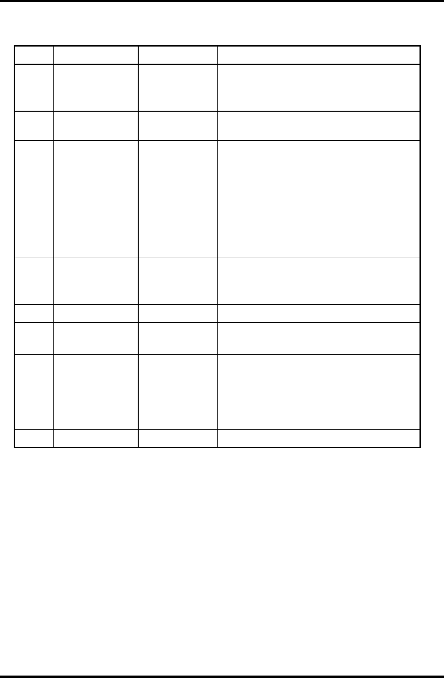
3 Tests and Diagnostics 3.3 Subtest Names
Table 3-1 Subtest names (2/2)
No. Test Name Subtest No. Subtest Name
6 PRINTER 01
02
03
Ripple pattern
Function
Wrap around
7 ASYNC 06
07
FIR/SIR Point to point (send)
FIR/SIR Point to point (receive)
8 HARD DISK 01
02
03
04
06
07
09
10
Sequential read
Address uniqueness
Random address/data
Cross talk & peak shift
Write specified address
Read specified address
Sequential write
W-R-C specified address
9 REAL TIMER 01
02
03
Real time
Backup memory
Real time carry
10 NDP 01 NDP test
11 EXPANSION 01
03
PCMCIA wrap around
RGB monitor ID
13 CD-ROM/DVD-
ROM
01
02
03
04
05
Sequential read
Read specified address
Random address/data
Playback music
RW 1Point W/R/C
14 LAN 01 LAN MAC ADDRESS DISPLAY
3-8 Satellite M30-35 Maintenance Manual (960-455)

3.4 System Test 3 Tests and Diagnostics
3.4 System Test
To execute the System Test select 1 from the DIAGNOSTIC TEST MENU, press Enter and
follow the directions on the screen. Move the highlight bar to the subtest you want to execute
and press Enter.
Subtest 01 ROM Checksum
This subtest executes a checksum test of the BIOS ROM (range: F0000h to
FFFFFh, 64KB) on the System Board.
Subtest 04 Fan ON/OFF
This subtest turns on/off the fan motor by force with Fan ON/OFF commands.
The following message will appear. Make sure the fan does not rotate and
press Enter.
*** Test Fan Revolution 0000RPM start
The following message will appear. Make sure the fan rotates at low speed
and press Enter.
*** Test Fan Revolution Low speed Start
The following message will appear. Make sure the fan rotates at high speed
and press Enter.
*** Test Fan Revolution High speed Start
Subtest 05 Geyserville
If the CPU supports Gerserville (SpeedStep), this Subtest checks that the CPU
operating clock speed can be changed.
Subtest 06 Quick Charge
This subtest checks the status for the quick charge.
Satellite M30-35 Maintenance Manual (960-455) 3-9

3 Tests and Diagnostics 3.4 System Test
Subtest 07 DMI read
This subtest displays the information in the Flash-ROM in the following
format.
*** DMI Data Display Ver X.XX ***
Model Name : XXXXXXXXXXX
Version Number : XXXXXXXXXXXX
Serial Number : XXXXXXXX
Model Number : XXXXXX-XXXXX
PCN/BND Number : XXXXXXXXXXXX/XXXXXXXXXXX
UUID Number : XXXXXXXXXXXXXXXXXXXXXXXXXXXXXXXX
Press [Enter] to EXIT
To exit this subtest and return to the SYSTEM test menu, press Enter.
Subtest 08 DMI write
The following messages appear in order. Input each information. (If you do
not replace the PCB, the DMI information should not be changed.)
1. “Enter Model Name ?” is displayed.
Input the computer’s model name and press Enter. (e.g. DynaBook)
2. “Enter Version Number ?” is displayed.
Input the computer’s version number and press Enter. (e.g.
PC18070C313S)
3. “Enter Serial Number ?” is displayed.
Input the computer’s serial number and press Enter. (e.g. 12345678)
4. “Enter Model Number ?” is displayed.
Input the computer’s sales model number and press Enter. (e.g. PP200-
AAAAA)
5. “Enter Bundle Number ?” is displayed.
Input the computer’s PCN/Bundle number and press Enter. (e.g.
PMSREQ3Q34H/S0123456789)
6. “Write data OK (Y/N) ?” is displayed.
To write the DMI information to the Flash ROM, press Y, and then Enter.
3-10 Satellite M30-35 Maintenance Manual (960-455)

3.4 System Test 3 Tests and Diagnostics
7. “Create DMIINFO TXT (Y/N) ?” is displayed.
Press Y, then the DMI information (text data) is written to the Floppy
disk, etc.
Subtest 10 CPU Temperature
This subtest checks the CPU temperature.
When the subtest starts, the following message appears on the display. Enter
the ambient Celsius temperature.
EXT. TEMP =
When the temperature is entered, test program turns off the screen message.
After 15 minutes, it measures the CPU temperature and judges the test result
(OK or NG) based on the gap between the ambient temperature and the
measured temperature (threshold value).
When any error occurs, an error log is written into “DIAGNOSTIC MENU: 5-
LOG UTILITIES”.
The meaning of “WD” or “RD” of the error log is as follows:
WD : Reference value of CPU temperature rising (hexadecimal form).
RD : Gap between the CPU temperature and the ambient temperature
(hexadecimal form).
Satellite M30-35 Maintenance Manual (960-455) 3-11

3 Tests and Diagnostics 3.5 Memory Test
3.5 Memory Test
To execute the Memory Test, select 2 from the DIAGNOSTIC TEST MENU, press Enter
and follow the directions on the screen. Move the highlight bar to the subtest you want to
execute and press Enter.
Subtest 01 Conventional memory
This subtest writes a constant data to conventional memory (0 to 640 KB),
then reads the new data and compares the result with the original data.
Subtest 02 Protected Mode
NOTE: The CONFIG.SYS file must be configured without expanded memory manager
programs such as EMM386.EXE, EMM386.SYS or QEMM386.SYS. Also, the
HIMEM.SYS must be deleted from the CONFIG.SYS file.
This subtest writes constant data and address data (from 1MB to maximum
MB), and reads the new data and compares the result with the original data.
Subtest 04 Cache Memory
To test the cache memory, a pass-through write-read comparison of ‘5Ah’
data is run repeatedly to the test area (‘7000’:’Program’ size to ‘7000’:’7FFF’
(32 KB)) to check the hit-miss ratio (on/off status) for CPU cache memory.
One test takes 3 seconds.
Number of misses < Number of hits → OK
Number of misses ≥ Number of hits → Fail
Subtest 05 L2 Cache Memory
To test the L2 cache memory, a similar test to that for the cache memory is
performed.
Subtest 06 Stress
Data (from 1MB to the maximum MB) is written from the 16KB write buffer
to the 16KB read buffer and compared the data in the buffers. The read buffer
starts from 0001 and the comparison is continued with the following read
buffer addresses: 0001, 0003, 0005, 0007, 0009, 000b, 000d and 000f.
3-12 Satellite M30-35 Maintenance Manual (960-455)
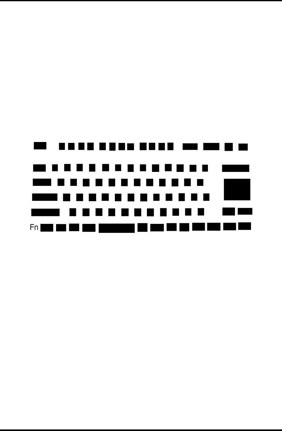
3.6 Keyboard Test 3 Tests and Diagnostics
3.6 Keyboard Test
To execute the Keyboard Test, select 3 from the DIAGNOSTIC TEST MENU, press Enter
and follow the directions on the screen. Move the highlight bar to the subtest you want to
execute and press Enter.
Subtest 01 Pressed key display
When you execute this subtest, the keyboard layout is drawn on the display as
shown below. When any key is pressed, the corresponding key on the screen
changes to the key character that was pressed. Holding a key down enables
the auto-repeat function which causes the key’s display character to blink.
Press Del + Enter to end the test.
Subtest 02 Pressed key code display
When a key is pressed, the scan code, character code, and key top name are
displayed on the screen in the format shown below. The Ins Lock, Caps
Lock, Num Lock, Scroll Lock, Alt, Ctrl, Left Shift, and Right Shift
keys are displayed in reverse screen mode when pressed. The scan codes,
character codes, and key top names are shown in Appendix D.
KEYBOARD TEST IN PROGRESS 302000
Scan code =
Character code =
Keytop =
Ins Lock Caps Lock Num Lock Scroll Lock
Alt Ctrl Left Shift Right Shift
PRESS [Enter] KEY
Satellite M30-35 Maintenance Manual (960-455) 3-13

3 Tests and Diagnostics 3.6 Keyboard Test
Subtest 04 Touch Pad
This subtest checks the functions of the touch pad as shown below.
A) Direction and parameter
B) Switching function check.
This test displays the response from the touch pad and touch pad switch.
When moving your finger on the touch pad towards the upper left, the
<POINTING> display changes according to the following illustration. If a
touch pad switch is pressed, the <BUTTONS> displays appear on the right
side one by one. The parameters appear above the <BUTTONS> (1) or (2)
corresponding to the pressed touch pad switch highlights. If two touch pad
switches are pressed at the same time, the subtest menu appears.
*
** IPS (PAD) TEST PROGRA
M
(Vx.xx) ***
<POINTING>
STATUS :0000h
■■
X-RATE :0000h
■■■■
Y-RATE :0000h
■■■■■■
■■■■■■
■■■■ <BUTTON>
■■ (1) (2)
<<Press BUTTON1 + BUTTON2 THEN END>>
<BUTTON>
(1) (2)
*** IPS (PAD) TEST PROGRAM (Vx.xx) ***
<<PRESS BUTTON1 + BUTTON2 THEN END>>
< POINTING > < PARAMETER >
STATUS : 0018h
X-RATE : OK
Y-RATE : OK
3-14 Satellite M30-35 Maintenance Manual (960-455)

3.6 Keyboard Test 3 Tests and Diagnostics
Subtest 05 USB (Port 0, Port1) test
This subtest checks USB. The USB TEST Module (ZD0003P01) and USB
Cable (ZD0003P02) must be connected to the computer.
The following message will appear. Select a port to test and press Enter.
Test port number select (1:Port0, 2:Port1, 0:Port0&1) ?
If the test ends successfully, OK is displayed. If there is a problem with the
USB port, an error message appears. Check the wraparound connection and
repeat the test.
Subtest 06 USB (Port 2) test
This subtest checks USB. The USB TEST Module (ZD0003P01) and USB
Cable (ZD0003P02) must be connected to the computer.
The following message will appear. Select a port to test and press Enter.
Test port number select (1:Port2, 2:Port3, 0:Port2&3) ?
If the test ends successfully, OK is displayed. If there is a problem with the
USB port, an error message appears. Check the wraparound connection and
repeat the test.
Subtest 07 Button test
This subtest checks the IE, Mail and TV button.
1. The following message is displayed. Press IE button.
Press [IE] Button
2. The following message is displayed. Press Mail button.
Press [Mail] Button
3. The message is displayed. Press TV button.
Press [TV] Button
Satellite M30-35 Maintenance Manual (960-455) 3-15

3 Tests and Diagnostics 3.7 Display Test
3.7 Display Test
To execute the Display Test, select 4 from the DIAGNOSTIC TEST MENU, press Enter
and follow the directions on the screen. Move the highlight bar to the subtest you want to
execute and press Enter.
Subtest 01 VRAM read/write for VGA
This subtest writes the constant data (AAh and 55h) to the video RAM. The
data is read and compared to the original data.
Subtest 02 Gradation for VGA
This subtest displays four colors: red, green, blue and white from left to right
across the screen from black to maximum brightness. The display below
appears on the screen, when this subtest is executed.
To exit this subtest and return to the DISPLAY TEST menu, press Enter.
Subtest 03 Gradation for LCD
This subtest displays bands of gradations for mixed colors, then for red, green,
and blue. Next, it displays eight solid colors full screen: red, semi-red, green,
semi-green, blue, semi-blue, white, and semi-white. Each color displays for
three seconds.
3-16 Satellite M30-35 Maintenance Manual (960-455)

3.7 Display Test 3 Tests and Diagnostics
Subtest 04 Gradation & Mode test for VGA
This subtest displays gradations for following modes. To change the mode,
press Enter.
[Mode 12]
[Mode 13]
[Mode 3]
[Mode 111 640*480 64K]
[Mode 112 640*480 16M]
[Mode 114 800*600 64K]
[Mode 115 800*600 16M]
[Mode 117 1024*768 64K]
[Mode 118 1024×768 16M]
The display below appears on the screen when this subtest is executed.
(Display example: Mode 12)
To exit this subtest and return to the DISPLAY TEST menu, press Enter after
displaying the Mode 118.
Subtest 05 All dot on/off for LCD
This subtest displays an all-white screen then an all-black screen. The display
changes automatically every three seconds, then returns to the DISPLAY
TEST menu.
Satellite M30-35 Maintenance Manual (960-455) 3-17

3 Tests and Diagnostics 3.7 Display Test
Subtest 06 “H” Pattern Display
This subtest displays a full screen of “H” patterns.
HHHHHHHHHHHHHHHHHHHHHHHHHHHHHHHHHHHHHHHHHHHHHHHHHH
HHHHHHHHHHHHHHHHHHHHHHHHHHHHHHHHHHHHHHHHHHHHHHHHHH
HHHHHHHHHHHHHHHHHHHHHHHHHHHHHHHHHHHHHHHHHHHHHHHHHH
HHHHHHHHHHHHHHHHHHHHHHHHHHHHHHHHHHHHHHHHHHHHHHHHHH
HHHHHHHHHHHHHHHHHHHHHHHHHHHHHHHHHHHHHHHHHHHHHHHHHH
HHHHHHHHHHHHHHHHHHHHHHHHHHHHHHHHHHHHHHHHHHHHHHHHHH
HHHHHHHHHHHHHHHHHHHHHHHHHHHHHHHHHHHHHHHHHHHHHHHHHH
HHHHHHHHHHHHHHHHHHHHHHHHHHHHHHHHHHHHHHHHHHHHHHHHHH
HHHHHHHHHHHHHHHHHHHHHHHHHHHHHHHHHHHHHHHHHHHHHHHHHH
HHHHHHHHHHHHHHHHHHHHHHHHHHHHHHHHHHHHHHHHHHHHHHHHHH
HHHHHHHHHHHHHHHHHHHHHHHHHHHHHHHHHHHHHHHHHHHHHHHHHH
HHHHHHHHHHHHHHHHHHHHHHHHHHHHHHHHHHHHHHHHHHHHHHHHHH
HHHHHHHHHHHHHHHHHHHHHHHHHHHHHHHHHHHHHHHHHHHHHHHHHH
HHHHHHHHHHHHHHHHHHHHHHHHHHHHHHHHHHHHHHHHHHHHHHHHHH
HHHHHHHHHHHHHHHHHHHHHHHHHHHHHHHHHHHHHHHHHHHHHHHHHH
To exit this subtest and return to the DISPLAY TEST menu, press Enter.
NOTE: The last row may not be completely filled. This condition does not indicate on
error.
Subtest 07 LCD Brightness
The LCD brightness changes in the following order:
Super-Bright —> Bright —> Semi-Bright —> Bright —> Super-Bright
3-18 Satellite M30-35 Maintenance Manual (960-455)
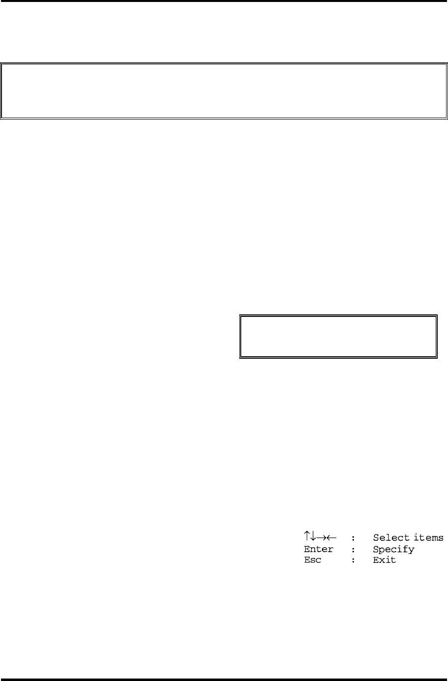
3.8 Floppy Disk Test 3 Tests and Diagnostics
3.8 Floppy Disk Test
CAUTION: Before running the floppy disk test, prepare a formatted work disk. Remove
the Diagnostics Disk and insert the work disk into the FDD. The contents of
the floppy disk will be erased.
To execute the Floppy Disk Test, select 5 from the DIAGNOSTIC TEST MENU, press
Enter and follow the directions displayed on the screen. After selecting the Floppy Disk Test
from the DIAGNOSTIC TEST MENU, messages to execute the test drive number, media
type and test start truck will be displayed successively. Answer each question with an
appropriate response to execute the test.
1. The following message will appear. Select the media mode and start track to be tested,
then press Enter.
Media in drive#1 mode (0:2DD, 1:2D, 2:2D-2HD/2DD, 3:2HD) ?
Test start track (Enter:0/dd:00-79) ?
2. The Floppy Disk test contains five subtests that test the FDD.
The floppy disk test menu will appear after you select FDD test parameters.
FLOPPY DISK XXXXXXX XXX DIAGNOSTIC TEST VX.XX
[Ctrl]+[Break] : test end
[Ctrl]+[C] : key stop
SUB-TEST : XX
PASS COUNT : XXXXX ERROR COUNT : XXXXX
WRITE DATA : XX READ DATA : XX
ADDRESS : XXXXXX STATUS : XXX
SUB-TEST MENU :
01 - Sequential read
02 - Sequential read/write
03 - Random address/data
04 - Write specified address
05 - Read specified address
99 - Exit to DIAGNOSTIC TEST MENU
Satellite M30-35 Maintenance Manual (960-455) 3-19

3 Tests and Diagnostics 3.8 Floppy Disk Test
Select the number of the subtest you want to execute and press Enter. The following
message will appear during the floppy disk test.
FLOPPY DISK IN PROGRESS XXXXXXX xxx DIAGNOSTIC TEST VX.XX
[Ctrl]+[Break] : test end
[Ctrl]+[C] : key stop
SUB-TEST : XX
PASS COUNT : XXXXX ERROR COUNT : XXXXX
WRITE DATA : XX READ DATA : XX
ADDRESS : XXXXXX STATUS : XXX
3. When the subtest 04 or 05 is selected, the following messages will appear on the screen.
Select the test data (subtest 04 only), track number and head number you want to test.
Test data ?? (subtest 04 only)
Track No. ??
Head No. ?
Subtest 01 Sequential read
This subtest performs a Cyclic Redundancy Check (CRC) that continuously
reads all the tracks (track: 0 to 39/0 to 79) on a floppy disk.
Subtest 02 Sequential read/write
This subtest continuously writes data pattern B5ADADh to all the tracks
(track: 0 to 39/0 to 79) on a floppy disk. The data is then read and compared
to the original data.
Subtest 03 Random address/data
This subtest writes random data to random addresses on all tracks (track: 0 to
39/0 to 79) on a floppy disk. The data is then read and compared to the
original data.
Subtest 04 Write specified address
This subtest writes the data specified by an operator to a specified track, head,
and address.
Subtest 05 Read specified address
This subtest reads data from a track, head, and address specified by an
operator.
3-20 Satellite M30-35 Maintenance Manual (960-455)
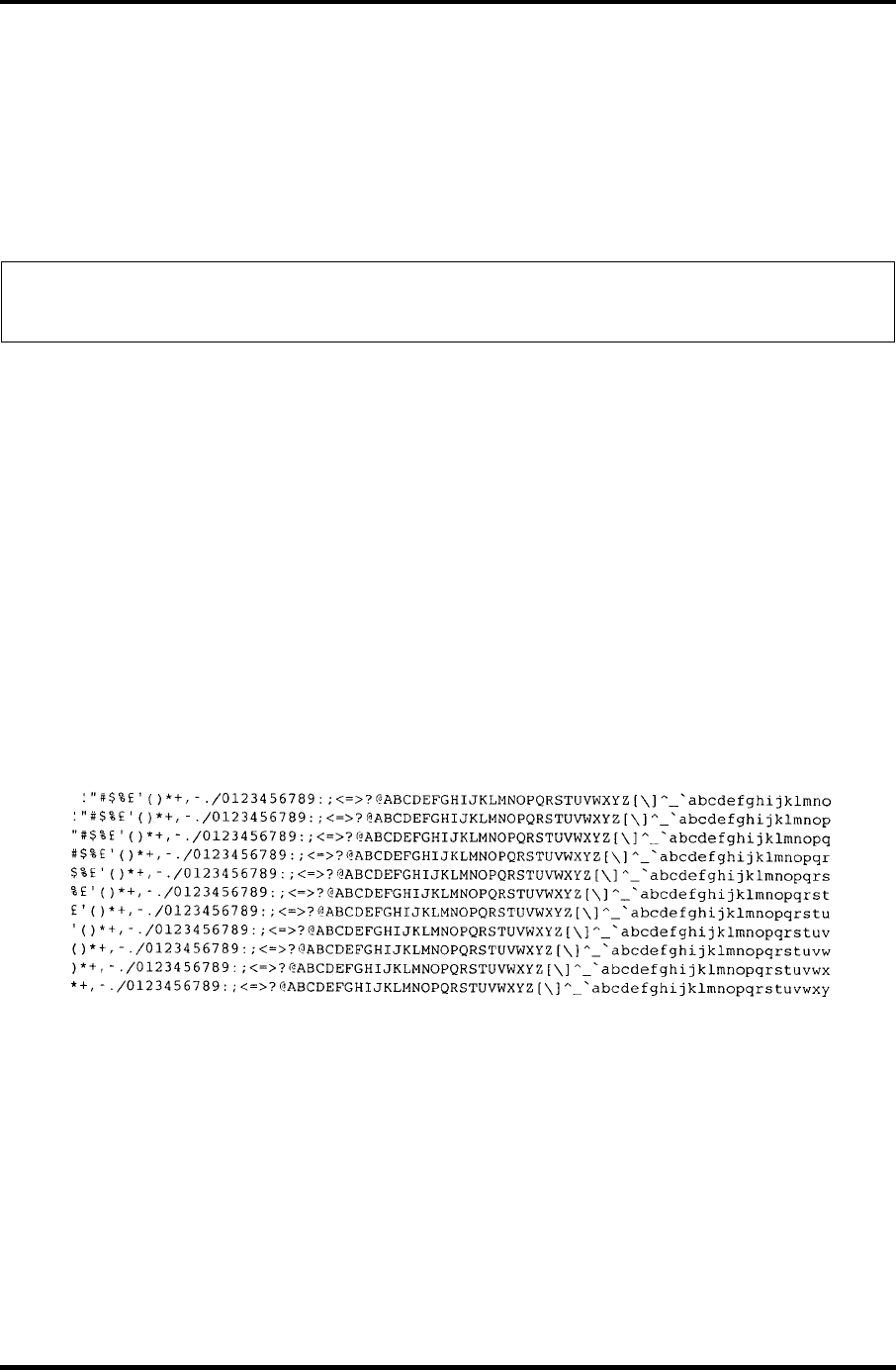
3.9 Printer Test 3 Tests and Diagnostics
3.9 Printer Test
To execute the Printer Test, select 6 from the DIAGNOSTIC TEST MENU, press Enter and
follow the directions on the screen. The following messages will appear after selecting the
Printer Test from the DIAGNOSTIC TEST MENU. Answer each of the questions with an
appropriate response to execute the test.
NOTE: A Port Replicator and an IBM compatible printer must be connected to the
system to execute this test.
The following message will appear, after selecting the subtest 01 to 03 of the printer test:
channel#1 = XXXXh
channel#2 = XXXXh
channel#3 = XXXXh
Select the channel number (1-3) ?
The printer I/O port address is specified by the XXXXh number. The computer supports
three printer channels. Select the printer channel number, and press Enter to execute the
selected subtest.
Subtest 01 Ripple Pattern
This subtest prints characters for codes 20h through 7Eh line-by-line while
shifting one character to the left at the beginning of each new line.
Satellite M30-35 Maintenance Manual (960-455) 3-21
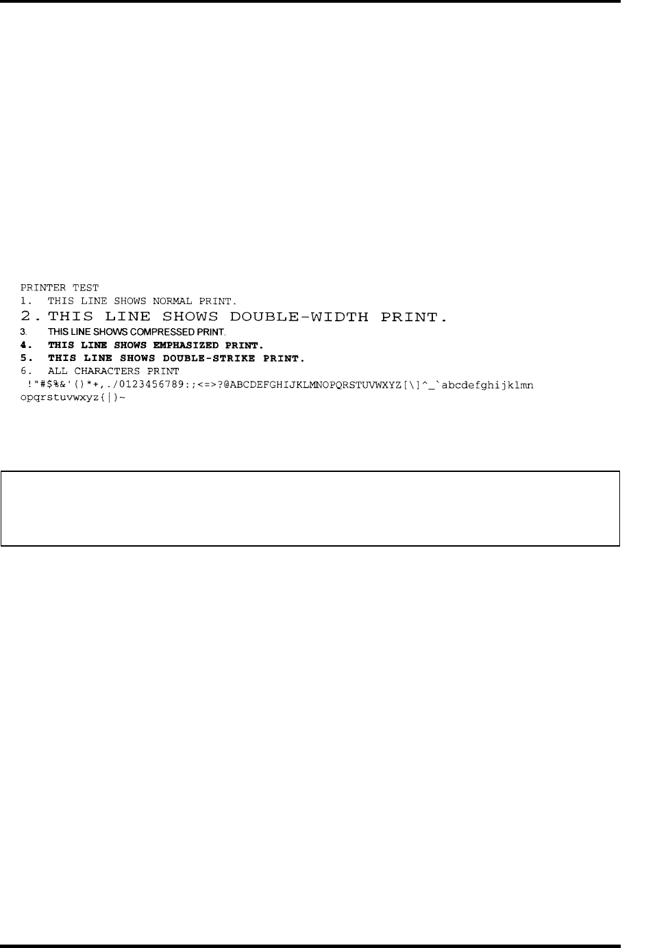
3 Tests and Diagnostics 3.9 Printer Test
Subtest 02 Function
This subtest is for IBM compatible printers, and tests the following functions:
Normal print
Double-width print
Compressed print
Emphasized print
Double-strike print
All characters print
This subtest prints the various print types shown below:
Subtest 03 Wraparound
NOTE: To execute this subtest, a printer wraparound connector must be connected to the
computer’s printer port. The connector wiring diagram is described in Appendix
F.
This subtest checks the output and bi-directional modes of the data control
and status lines through the parallel port wraparound connector
(34M741986G01). (Both output and bi-directional modes are tested.)
3-22 Satellite M30-35 Maintenance Manual (960-455)

3.10 Async Test 3 Tests and Diagnostics
3.10 Async Test
To execute the Async Test, select 7 from the DIAGNOSTIC TEST MENU, press Enter and
follow the directions displayed on the screen. Move the highlight bar to the subtest you want
to execute and press Enter.
Subtests 06 and 07 require the following data format:
Method: Asynchronous
Speed: 38400BPS
Data: 8 bits and one parity bit (EVEN)
Data pattern: 20h to 7Eh
Subtest 06 FIR/SIR Point to point (send)
NOTE: To execute subtests 06 and 07, each computer must have access to the other
computer’s infrared port.
This subtest sends 20h through 7Eh data to the receive side, then receives the
sent data and compares it to the original data through the FIR/SIR port.
Subtest 07 FIR/SIR Point to point (receive)
This subtest is used with subtest 06 described above. This subtest receives the
data from the send side, then sends the received data through the FIR/SIR
port.
Satellite M30-35 Maintenance Manual (960-455) 3-23

3 Tests and Diagnostics 3.11 Hard Disk Test
3.11 Hard Disk Test
To execute the Hard Disk Test, select 8 from the DIAGNOSTIC TEST MENU, press Enter,
and follow the directions on the screen.
CAUTION: The contents of the hard disk will be erased when subtest 01, 02, 03, 04, 06,
07,09, or 10 is executed. Before running the test, the customer should
transfer the contents of the hard disk to floppy disk or another hard disk. If
the customer has not or cannot perform the back-up, create back-up disks as
described below.
Check to see if the Microsoft Create System Disks Tools (MSCSD.EXE) still
exists in the System Tools Folder. (This tool can be used only once.) If it
exists, use it to back up the pre-installed software, then use the Backup
utility in the System Tools folder to back up the entire disk, including the
user’s files.
Refer to the operating system instructions.
The following messages will appear after selecting the hard disk test from the DIAGNOSTIC
TEST MENU.
Test drive number select (1:HDD#1, 2:HDD#2, 0:HDD#1&2) ?
HDC F/W error retry (1:yes, 2:no) ?
↑↓→←: Select items, Enter : Specify, Esc : Exit
1. This message is used to select the error dump operation when a data compare error is
detected. Select yes or no.
Data compare error dump (1:no, 2:yes)
2. This message is used to select whether or not the HDD status is displayed on the
screen. The HDD status is described in section 3.18. Select yes or no.
Detail status display (1:no, 2:yes)
3-24 Satellite M30-35 Maintenance Manual (960-455)

3.11 Hard Disk Test 3 Tests and Diagnostics
3. The Hard Disk Test message will appear after you respond to the Detail Status
prompt. Select the number of the subtest you want to execute and press Enter. The
following message will appear during each subtest.
HARD DISK TEST XXXXXXX XXX DIAGNOSTIC TEST VX.XX
[Ctrl]+[Break] : test end
[Ctrl]+[C] : key stop
SUB TEST : XX
PASS COUNT : XXXXX ERROR COUNT : XXXXX
WRITE DATA : XX READ DATA : XX
ADDRESS : XXXXXX STATUS : XXX
The first three digits of the ADDRESS indicate which cylinder is being tested, the
fourth digit indicates the head and the last two digits indicate the sector.
The first digit of the STATUS number indicates the drive being tested and the last
two digits indicate the error status code as explained in table 3-2 of the section 3.17.
Subtest 01 Sequential read
This subtest is a sequential reading of all the tracks on the HDD starting at
track 0. When all the tracks on the HDD have been read, the test starts at the
maximum track and reads the tracks on the HDD sequentially back to track 0.
Subtest 02 Address uniqueness
This subtest writes unique address data to each sector of the HDD track-by-
track. The data written to each sector is then read and compared with the
original data. There are three ways the HDD can be read:
1. Forward sequential
2. Reverse sequential
3. Random
Subtest 03 Random address/data
This subtest writes random data in a random length to random addresses. This
data is then read and compared to the original data.
Satellite M30-35 Maintenance Manual (960-455) 3-25
3 Tests and Diagnostics 3.11 Hard Disk Test
3-26 Satellite M30-35 Maintenance Manual (960-455)
Subtest 04 Cross talk & peak shift
This subtest writes eight types of worst pattern data (listed below) to a
cylinder, then reads the data while moving from cylinder to cylinder. (Test the
data interference in the neighbor track)
Worst pattern data Cylinder
‘B5ADAD’ 0 cylinder
‘4A5252’ 1 cylinder
‘EB6DB6’ 2 cylinder
‘149249’ 3 cylinder
’63B63B’ 4 cylinder
‘9C49C4’ 5 cylinder
‘2DB6DB’ 6 cylinder
‘D24924’ 7 cylinder
Subtest 06 Write specified address
This subtest writes specified data to a specified cylinder and head on the
HDD.
Subtest 07 Read specified address
This subtest reads data, which has been written to a specified cylinder and
head on the HDD.
Subtest 09 Sequential write
This subtest writes specified 2-byte data to all of the cylinders on the HDD.
Subtest 10 W-R-C specified address
This subtest writes data to a specified cylinder and head on the HDD, then
reads the data and compares it to the original data.

3.12 Real Timer Test 3 Tests and Diagnostics
3
3.12 Real Timer Test
To execute the Real Timer Test, select 9 from the DIAGNOSTIC TEST MENU, press Enter
and follow the directions on the screen. Move the highlight bar to the subtest you want to
execute and press Enter.
Subtest 01 Real time
A new date and time can be input during this subtest. To execute the real time
subtest follow these steps:
1. Select subtest 01 and the following messages will appear:
Current date : XX-XX-XXXX
Current time : XX:XX:XX
Enter new date:
PRESS [ENTER] KEY TO EXIT TEST
2. If the current date is not correct, input the correct date at the “Enter new
date” prompt and press Enter.
3. The following messages will appear:
Current date : XX-XX-XXXX
Current time : XX:XX:XX
Enter new time:
PRESS [ENTER] KEY TO EXIT TEST
4. If the current time is not correct, input the correct time in 24-hour format.
To enter ":", press Shift + ;. The time is updated.
To exit, press Enter.
Subtest 02 Backup memory
This subtest checks the following backup memories:
Writes 1-bit of “on” data (01h through 80h) to address 0Eh through 7Fh
Writes 1-bit of “off” data (FEh through 7Fh) to address 0Eh through 7Fh
Writes the data pattern AAh and 55h to the address 0Eh to 7Fh
Then the subtest reads and compares this data with the original data.
Satellite M30-35 Maintenance Manual (960-455) 3-27

3 Tests and Diagnostics 3.12 Real Timer Test
Subtest 03 Real time carry
CAUTION: When this subtest is executed, the current date and time are erased.
This subtest checks the real time clock increments, making sure the date and
time are displayed in the following format:
Current date : 12-31-1999
Current time : 23:59:58
The real time increments are automatically executed and the following is
displayed:
Current date : 01-01-2000
Current time : 00:00:00
PRESS [Enter] KEY TO EXIT TEST
Press Enter to exit.
3-28 Satellite M30-35 Maintenance Manual (960-455)

3.13 NDP Test 3 Tests and Diagnostics
3.13 NDP Test
To execute the NDP test, select 10 from the DIAGNOSTICS TEST MENU, press Enter and
follow the directions on the screen.
Subtest 01 NDP
This test checks the following functions of NDP:
Control word
Status word
Bus
Addition
Multiplication
Satellite M30-35 Maintenance Manual (960-455) 3-29
3 Tests and Diagnostics 3.14 Expansion Test
3.14 Expansion Test
To execute the expansion test, select 11 from the DIAGNOSTICS TEST MENU, press Enter
and follow the directions on the screen.
NOTE: To execute this subtest, the PC card wraparound connector is required.
Subtest 01 PCMCIA wrap around
This subtest checks the following signal line of the PC card slot:
Address line
REG#, CE#1, CE#2 line
Data line
Speaker line
Wait line
BSY#, BVD1 line
This subtest is executed in the following order:
Sub# Address Good Bad Contents
01 00001
00001
nn
nn
xx
xx
Address line
REG#, CE#1, CE#2
nn=A0, 90, 80, 00
02 00002 ww rr Data line
ww=write data, rr=read
data
03 00003 –– –– Speaker line
04 00004 40,80 xx Wait line (40<xx<80)
05 00005 nn xx Other lines (BSY#, BVD1)
NN=21, 00
NOTE: Select the subtest number01, The following message will appear:
Test slot number select (1:slot0, 2:slot1, 0:slot0&1)?
Subtest 03 RGB monitor ID
Connect a wraparound connector to CRT monitor for the test of ID acquisition.
This subtest is executed by using VESA command.
3-30 Satellite M30-35 Maintenance Manual (960-455)

3.15 CD-ROM/DVD-ROM Test 3 Tests and Diagnostics
3.15 CD-ROM/DVD-ROM Test
To execute the CD-ROM/DVD test, select 13 from the DIAGNOSTICS TEST MENU, press
Enter and follow the directions on the screen.
NOTE: For the subtest 01, 02 and 03, use the TOSHIBA CD-ROM TEST DISK
(ZA1217P01/P000204190) for CD-ROM and DVD-ROM TEST DISK TSD-1 for
DVD-ROM. For the subtest 04, use a music CD on the market. For the subtest 05,
use a CD-RW on the market.
Subtest 01 Sequential read
This subtest is a sequential reading of one-block units (2K bytes) of all the
logical addresses.
Subtest 02 Read specified address
This subtest reads one-block data from a specified address.
Subtest 03 Random address/data
This subtest reads one-block data and multi-block data from random addresses
200 times.
Subtest 04 Playback Music (CD only)
This subtest reads track data from a specified track and plays the sound.
CAUTION: When the CD-ROM test is executed, “ALL DEVICE” must be selected in the
“SET-UP” of the BIOS SETUP. If the “ALL DEVICE” is not selected, music
can not be played.
Subtest 05 RW 1Point W/R/C
This subtest writes, reads and compares data at one point on a CD/RW media.
Satellite M30-35 Maintenance Manual (960-455) 3-31

3 Tests and Diagnostics 3.16 LAN test
3.16 LAN test
To execute the LAN test, select 14 from the DIAGNOSTICS TEST MENU, press Enter and
follow the directions on the screen. The LAN test contains one subtest.
Subtest 01 LAN MAC ADDRESS DISPLAY
This subtest reads MAC ADDRESS and displays it.
Press Enter to exit.
3-32 Satellite M30-35 Maintenance Manual (960-455)

3.17 Error Code and Error Status Names 3 Tests and Diagnostics
3.17 Error Code and Error Status Names
Table 3-2 lists the error codes and error status names for the Diagnostic Test.
Table 3-2 Error codes and error status names (1/3)
Device name Error code Error status name
(Common) FF Data Compare Error
System 01
02
03
ROM Checksum Error
Location ID Error
Serial ID Write Error
Memory 01
02
14
DD
DE
DF
Parity Error
Protected Mode Not Changed
Memory Read/Write Error
Cache Memory Error
2nd Cache Error
TAG-RAM Error
Keyboard 01
02
03
04
05
06
Mouse Interface Error
IPS Interface Error
Interface Error
Retransmit Error
Mouse Handler Not Support
PS/2 Mouse & IPS Not Support
FDD 01
02
03
04
06
08
09
10
20
40
60
80
EE
Bad Command Error
Address Mark Not Found
Write Protected
Record Not Found
Media Removed
DMA Overrun Error
DMA Boundary Error
CRC Error
FDC Error
Seek Error
Not Drive Error
Time Out Error
Write Buffer Error
Printer 01
08
10
20
40
80
Time Out
Fault
Select Line
Out Of Paper
Power Off
Busy Line
Satellite M30-35 Maintenance Manual (960-455) 3-33
3 Tests and Diagnostics 3.17 Error Code and Error Status Names
Table 3-2 Error codes and error status names (2/3)
Device name Error code Error status name
ASYNC 01
02
04
08
10
20
40
50
60
70
80
DSR On Time Out
CTS On Time Out
RX-READY Time Out
TX-FULL Time Out
Parity Error
Framing Error
Overrun Error
Underrun error
Timer time out error
CRC error
Line Status Error
HDD 01
02
04
05
07
08
09
0A
0B
10
11
20
40
80
AA
BB
CC
E0
EE
DA
Bad Command Error
Address Mark Not Found
Record Not Found
HDC Not Reset Error
Drive Not Initialized
HDC Overrun (DRQ)
DMA Boundary Error
Bad Sector
Bad Track Error
ECC Error
ECC Recover Enable
HDC Error
Seek Error
Time Out Error
Drive Not Ready
Undefined Error
Write Fault
Status Error
Access Time Out Error
No HDD
NDP 01
02
03
04
05
06
No Co-Processor
Control Word Error
Status Word Error
Bus Error
Addition Error
Multiply Error
3-34 Satellite M30-35 Maintenance Manual (960-455)
3.17 Error Code and Error Status Names 3 Tests and Diagnostics
Table 3-2 Error codes and error status names (3/3)
Device name Error code Error status name
Expansion C1
C2
C3
C4
C5
C6
C7
C8
CB
CD
Address Line Error
REG# Line Error
CE#1 Line Error
CE#2 Line Error
DATA Line Error
WAIT Line Error
BSY# Line Error
BVD1 Line Error
ZV Port Error
No PCMCIA
CD/DVD-ROM 01
02
03
04
05
06
09
11
20
40
80
90
B0
Bad Command
Illegal Length
Unit Attention
Media Change Request
Media Detected
Additional Sense
Boundary Error
Corrected Data Error
Drive Not Ready
Seek Error
Time Out
Reset Error
Address Error
Satellite M30-35 Maintenance Manual (960-455) 3-35
3 Tests and Diagnostics 3.18 Hard Disk Test Detail Status
3.18 Hard Disk Test Detail Status
When an error occurs in the hard disk test, the following message is displayed:
HDC status = XXXXXXXX
Detailed information about the hard disk test error is displayed on the screen by an eight-digit
number. The first four digits represent the hard disk controller (HDC) error status number and
the last four digits are not used.
The hard disk controller error status is composed of two bytes; the first byte displays the
contents of the HDC status register in hexadecimal form and the second byte displays the
HDC error register.
The contents of the HDC status register and error register are listed in Tables 3-3 and 3-4.
Table 3-3 Hard disk controller status register contents
Bit Name Description
7 BSY
(Busy)
“0” … HDC is ready.
“1” … HDC is busy.
6 DRY
(Drive ready)
“0” … Hard disk drive is not ready to accept any command.
“1” … Hard disk drive is ready.
5 DWF
(Drive write fault)
“0” … DWF error is not detected.
“1” … Write fault condition occurred.
4 DSC
(Drive seek complete)
“0” … The hard disk drive heads are not settled over a track.
“1” … The hard disk drive heads are settled over a track.
3 DRQ
(Data request)
“0” … Drive is not ready for data transfer.
“1” … Drive is ready for data transfer.
2 COR
(Corrected data)
“0” … Not used
“1” … Correctable data error is corrected.
1 IDX
(Index)
“0” … Not used
“1” … Index is sensed.
0 ERR
(Error)
“0” … Normal
“1” … The previous command was terminated with an error.
3-36 Satellite M30-35 Maintenance Manual (960-455)
3.18 Hard Disk Test Detail Status 3 Tests and Diagnostics
Table 3-4 Error register contents
Bit Name Description
7 BBK
(Bad block mark)
“0” … Not used
“1” … A bad block mark is detected.
6 UNC
(Uncorrectable)
“0” … There is no uncorrectable data error.
“1” … Uncorrectable data error has been detected.
5 —— Not used
4 IDN
(Identification)
“0” … Not used
“1” … There is no ID field in the requested sector.
3 —— Not used
2 ABT
(Abort)
“0” … Not used
“1” … Illegal command error or command abort.
1 TK0
(Track 0)
“0” … The hard disk found track 0 during a recalibrate
command.
“1” … The hard disk could not find track 0 during a
recalibrate command.
0 —— Not used
Satellite M30-35 Maintenance Manual (960-455) 3-37

3 Tests and Diagnostics 3.19 Head Cleaning
3.19 Head Cleaning
3.19.1 Function Description
This function cleans the heads in the FDD by executing a series of head load/seek and read
operations. A cleaning kit is necessary to perform this program.
3.19.2 Operations
1. Selecting test 4 from the DIAGNOSTIC MENU and pressing Enter displays the
following messages:
DIAGNOSTICS - FLOPPY DISK HEAD CLEANING : VX.XX
Mount cleaning disk(s) on drive(s).
Press any key when ready.
2. Remove the Diagnostics Disk from the FDD, then insert the cleaning disk and press
Enter.
3. When the
“cleaning start” message appears, the FDD head cleaning has begun.
4. The display automatically returns to the DIAGNOSTIC MENU when the program is
completed.
3-38 Satellite M30-35 Maintenance Manual (960-455)

3.20 Log Utilities 3 Tests and Diagnostics
3.20 Log Utilities
3.20.1 Function Description
This function logs error information generated while a test is in progress and stores the results
in RAM. This function can store data on a floppy disk or output the data to a printer.
The error information is displayed in the following order:
1. Error count (CNT)
2. Test name, Subtest number (TS-No)
3. Pass count (PASS)
4. Error status (STS)
5. FDD/HDD or memory address (ADDR)
6. Write data (WD)
7. Read data (RD)
8. HDC status (HSTS)
9. Error status name (ERROR STATUS NAME)
If the power switch is turned off, the error information will be lost.
Satellite M30-35 Maintenance Manual (960-455) 3-39

3 Tests and Diagnostics 3.20 Log Utilities
3.20.2 Operations
1. Selecting 5 and pressing Enter in the DIAGNOSTIC MENU, logs error information
into RAM or onto a floppy disk. The error information is displayed in the following
format:
XXXXX ERRORS
CNT TS-NO PASS STS ADDR WD RD HSTS [ERROR STATUS NAME]
001 FDD 02 0000 103 00001 00 00 0000 FDD-WRITE PROTECTED
001 FDD 01 0000 180 00001 00 00 0000 FDD-TIME OUT ERROR
Error count
Pass count
Error status
Address
Subtest number
Test name
[[1:Next,2:Prev,3:Exit,4:Clear,5:Print,6:FD Log Read,7:FD Log Write]]
2. The error information displayed on the screen can be manipulated by the following
number keys:
The 1 key scrolls the display to the next page.
The 2 key scrolls the display to the previous page.
The 3 key returns to the Diagnostic Menu.
The 4 key erases all error log information in RAM.
The 5 key outputs the error log information to a printer.
The 6 key reads the log information from a floppy disk.
The 7 key writes the log information to a floppy disk.
3. In the case of “error retry OK,” a capital “R” will be placed at the beginning of the
error status. However, it is not added to the error count.
Error status name
Read data
Write data
HDC status
3-40 Satellite M30-35 Maintenance Manual (960-455)

3.21 Running Test 3 Tests and Diagnostics
3.21 Running Test
3.21.1 Function Description
This function automatically executes the following tests in sequence:
1. System test (subtest 01)
2. Memory test (subtests 01, 02 and 04)
3. Display test (subtest 01)
4. FDD test (subtest 02)
5. HDD test (subtests 01 and 05)
6. Real timer test (subtest 02)
7. Printer test (subtest 03) if selected
The system automatically detects the number of floppy disk drives connected to the computer
for the FDD test.
3.21.2 Operations
CAUTION: Do not forget to load a work disk in the FDD. If a work disk is not loaded, an
error will be generated during the FDD testing.
1. Remove the diagnostics disk from the floppy disk drive and insert the formatted work
disk.
2. Select 6 from the Diagnostic Menu and press Enter, the following message displays:
Printer wrap around test (Y/N) ?
Selecting Y (yes) executes the printer wraparound test. A printer wraparound
connector must be connected to the parallel port of the computer to properly execute
this test.
3. Select Y or N and press Enter. The following message will appear:
Serial #A wrap around test (Y/N) ?
Selecting Y (yes) executes the ASYNC wraparound test. An RS-232-C wraparound
connector must be connected to the serial port of the computer to properly execute this
test.
4. Select Y or N and press Enter.
5. This program is executed continuously. To terminate the program, press Ctrl +
Break.
Satellite M30-35 Maintenance Manual (960-455) 3-41

3 Tests and Diagnostics 3.22 Floppy Disk Drive Utilities
3.22 Floppy Disk Drive Utilities
3.22.1 Function Description
This function formats the FDD, copies the floppy disk and displays the dump list for both the
FDD and HDD.
1. FORMAT
NOTE: This program is only for testing a floppy disk drive. The option is different from
the Toshiba MS-DOS FORMAT command.
This program can format a 3.5-inch floppy disk in the following formats:
(a) 2D: Double-sided, double-density, 48/67.5 TPI, MFM mode, 512 bytes, 9
sectors/track.
(b) 2DD: Double-sided, double-density, double-track, 96/135 TPI, MFM mode,
512 bytes, 9 sectors/track.
(c) 2HD: Double-sided, high-density, double-track, 96/135 TPI, MFM mode, 512
bytes, 18 sectors/track.
2. COPY
This program copies data from a source floppy disk to a target floppy disk.
3. DUMP
This program displays the contents of the floppy disk and the designated sectors of
the hard disk on the display.
4. HDD ID READ
This program reads the hard disk ID and displays the hard disk ID, serial number and
other hard disk information.
3-42 Satellite M30-35 Maintenance Manual (960-455)

3.22 Floppy Disk Drive Utilities 3 Tests and Diagnostics
3.22.2 Operations
1. Selecting 7 from the DIAGNOSTIC MENU and pressing Enter displays the
following message:
[ FDD UTILITIES ]
1 - FORMAT
2 - COPY
3 - DUMP
4 – HDD-ID READ
9 - EXIT TO DIAGNOSTICS MENU
2. FORMAT program
(a) Selecting FORMAT displays the following message:
DIAGNOSTICS - FLOPPY DISK FORMAT : VX.XX
Drive number select (1:A, 2:B) ?
(b) Select a drive number to display the following message:
Type select (0:2DD, 3:2HD) ?
(c) Select a media/drive type number and press Enter. A message similar to the
one below will be displayed:
Warning : Disk data will be destroyed.
Insert work disk into drive A:
Press any key when ready.
(d) Remove the Diagnostics Disk from the FDD, insert the work disk and press
any key.
The following message will be displayed when the FDD format is executed:
[ FDD TYPE ] : TRACK = XXX
[ FDD TYPE ] : HEAD = X
[ FDD TYPE ] : SECTOR = XX
Format start
[[track, head = XXX X]]
After the floppy disk is formatted, the following message will appear:
Format complete
Another format (1:Yes/2:No) ?
(e) Typing 1 displays the message from step (c) above. Typing 2 returns the test
to the DIAGNOSTIC MENU.
Satellite M30-35 Maintenance Manual (960-455) 3-43

3 Tests and Diagnostics 3.22 Floppy Disk Drive Utilities
3. COPY program
(a) When COPY is selected, the following message appears:
FLOPPY DISK FORMAT & COPY : VX.XX
Type select (0:2DD,3:2HD) ?
(b) Selecting a media/drive type number will display a message similar to the one
below:
Insert source disk into drive A:
Press any key when ready.
(c) Remove the Diagnostics Disk from the FDD, insert the source disk and press
any key. The following message will appear, indicating the program has
started.
[ FDD TYPE ] : TRACK = XXX
[ FDD TYPE ] : HEAD = X
[ FDD TYPE ] : SECTOR = XX
Copy start
[[ track,head = XXX X ]]
(d) The following message will appear.
Insert target disk into drive A:
Press any key when ready.
(e) Remove the source disk from the FDD, then insert a formatted work disk and
press any key. The following message will appear and start copying to the
target disk.
[[ track,head = XXX X ]]
(f) When the amount of data is too large to be copied in one operation, the
message from step (b) is displayed again. After the floppy disk has been
copied, the following message will appear:
Copy complete
Another copy (1:Yes/2:No) ?
(g) To copy another disk, type 1 and the message from step (a) is displayed again.
Entering 2 returns the test program to the DIAGNOSTIC MENU.
3-44 Satellite M30-35 Maintenance Manual (960-455)

3.22 Floppy Disk Drive Utilities 3 Tests and Diagnostics
4. DUMP program
(a) When DUMP is selected, the following message appears:
DIAGNOSTICS-HARD DISK & FLOPPY DISK DUMP : VX.XX
Drive type select (1:FDD, 2:HDD) ?
(b) Select a drive type. If 2:HDD is selected, the display will go to step (h). If
1:FDD is selected, the following message will appear:
Select drive number (1:A, 2:B) ?
(c) Select a drive number and the following message will be displayed.
Format type select (1:2DD, 3:2HD) ?
(d) If 3:2HD is selected, the following message will appear. Select a media mode.
2HD media mode (1:1.20MB, 2:1.44MB, 3:1.23MB)?
(e) The following message will appear:
Insert source disk into drive A:
Press any key when ready.
(f) Insert a source disk and press any key and the following message will appear:
—— Max. address ——
[Track ] = XXXX
[Head ] = XX
[Sector] = XX
Track number ????
(g) Set the track number, head number and sector number you want to dump. The
system will access the disk and dump a list. Then the message shown in (k)
will appear.
(h) The following message will appear when selecting 2:HDD in (a).
Select drive number (1:C, 2:D) ?
(i) Select a drive number and the following message will be displayed.
---Max. address ---
[LBA ] = XXXXXXXXX
LBA number ????????
(j) Set the LBA number you want to dump. The system will access the disk and
dump a list.
Satellite M30-35 Maintenance Manual (960-455) 3-45

3 Tests and Diagnostics 3.22 Floppy Disk Drive Utilities
3-46 Satellite M30-35 Maintenance Manual (960-455)
(k) The following message will appear. To finish the dump, select 3.
Press number key (1:up,2:down,3:end) ?
(l) The following message will appear. Selecting 2 returns to the FDD
UTILITIES MENU.
Another dump (1:Yes,2:No) ?
5. HDD ID READ program
Selecting HDD ID displays the following HDD ID configuration:
[HDD ID Read (VX.XX)] [Drive #X]
ID code (h) = XXXX
No. of Cylinders = XXXX XXXX
Removable Cylinders = XXXX XXXX
No. of Heads = XXXX XXXX
Unformat Bytes/Track = XXXX XXXX
Unformat Bytes/Sector = XXXX XXXX
Sectors/Track = XXXX XXXX
Gap Length = XXXX XXXX
Sync. Bytes = XXXX XXXX
Reserved (h) = XXXX
Serial No. = YYY...
Controller Type (h) = XXXX
Sector Buffers = XXXX XXXX
ECC Bytes = XXXX XXXX
Firmware Rev. = YYYYYY..
Model No. = YYYY...
Reserved (h) = XXXX
Double Word Capability = XXXX XXXX
Press [Enter] key
Press Enter to return to the FDD UTILITIES MENU.

3.23 System Configuration 3 Tests and Diagnostics
3
3.23 System Configuration
3.23.1 Function Description
The System Configuration program contains the following configuration information for the
computer:
1. Processor Type
2. VGA Controller
3. MS-DOS Version
4. BIOS ROM version (1st ID, 2nd ID)
5. Boot ROM version
6. KBC version
7. PS Microprocessor Version (EC Version)
8. Total Memory Size
9. Battery code
10. Sound System
11. The number of printer ports
12. The number of ASYNC ports
13. The number of math co-processors
14. PCMCIA Slot
15. Modem/LAN Type
16. The number of floppy disk drives
17. The number of hard disk drives
18. The number of HWSC
19. The number of Wireless LAN
20. The number of Bluetooth
21. The number of IEEE1394
22. The number of USB2.0, FIR
23. Date/Time
Satellite M30-35 Maintenance Manual (960-455) 3-47

3 Tests and Diagnostics 3.23 System Configuration
3.23.2 Operations
Selecting 8 from the DIAGNOSTIC MENU and pressing Enter displays the following
system configuration:
System Configuration Display : Ver X.XX [Machine Name ???]
* - Processor Type = XXXXXX
* - VGA Controller = XXXXXX
* - MS-DOS Version = V7.XX
* - BIOS ROM Version = VX.XX 1st ID = XXH, 2nd ID = XXH
* - BOOT ROM Version = VX.XX
* - KBC Version = VX.XX
* - PS Micon Version = V1.XX ( EC Version = VX.XX )
* - Total Memory Size = XXXXXXMB ( Conventional Memory = 00639KB )
* - Battery Code = XXXXX
* - Sound System = XXXXX
* - X Printer Adapter LPT1 = 0378 LPT2 = XXXX LPT3 = XXXX
* - X ASYNC Adapter COM1 = 03F8 COM2 = XXXX COM3 = XXXX
* - X Math CO-Processor
* - X PCMCIA Slot
* - X MODEM / LAN
* - X Floppy Disk Drive(s) Track = XX Head = XX, Sector = XX
* - X Hard Disk Drive(s) #1 Sectors = XXXXX, (XXXXX MB)
* - X HWSC = XXXXXXX #2 Sectors = XXXXX, (XXXXX MB)
* - X Wireless LAN
* - X Bluetooth
* - X IEEE1394
* - X USB2.0、FIR
Press [Enter] Key [Date = XXXX-YY-ZZ, XX:YY:ZZ]
Press Enter to return to the DIAGNOSTIC MENU.
3-48 Satellite M30-35 Maintenance Manual (960-455)

3.24 Wireless LAN Test Program (Calexico) 3 Tests and Diagnostics
3.24 Wireless LAN Test Program (Calexico)
This section describes how to perform the wireless LAN transmitting-receiving test with the
test program.
NOTE: Use another computer (with Calexico wireless LAN card) that can communicate
by the wireless LAN as a reference machine to perform this test. An access point
is also required.
In this test, the following items are tested.
(1) Communication test (Main antenna, Aux antenna)
(2) MAC address Check
To start the Wireless LAN test program, follow the steps below:
NOTE: Before starting the wireless LAN test, make sure the Wireless Communication
Switch on the left side of the computer is turned on. (The Wireless
Communication LED lights orange.) Release the write-protection of the floppy
disk for the test.
Setting the responder machine
Connect the responder machine to the access point with a cross cable and turn on the access
point.
Insert the floppy disk containing the wireless LAN test program into the USB FDD of the
responder machine and turn on the responder machine. Then wait until the following
message appears.
Setting the target machine
Insert the floppy disk containing the wireless LAN test program into the USB FDD of the
target machine and turn on the target machine. Then the test starts automatically.
When the machine has passed the test, “OK !” message will appear on the target machine.
Press any key to exit the test.
When an error is detected during the test, “NG !” massage will appear. Press any key to
display the NG item (Main antenna, Aux. antenna or MAC address check). The following
message appears.
*************************************************************
* *
* Main Antenna Test: NG !! *
* *
*************************************************************
Satellite M30-35 Maintenance Manual (960-455) 3-49
3 Tests and Diagnostics 3.25 Wireless LAN Test Program (Atheros 11b/g or 11a/b/g)
3.25 Wireless LAN Test Program (Atheros 11b/g or 11a/b/g)
This section describes how to perform the wireless LAN transmitting-receiving test with the
test program.
NOTE: Use another computer (with Atheros 11b/g or 11a/b/g wireless LAN
card) that can communicate by the wireless LAN as a responder machine to
perform this test.
When conducting this test, make sure that any wireless network device using
2.4GHz band other than IEEE 802.11b, such as Bluetooth, is not used nearby.
In this test, the following items are tested:
* Test PC side
(1) SKU (destination code) check
(2) Mac Address check
(3) Communication test (11a mode) (only for 11a/b/g card)
(4) Communication test (11g mode)
(5) Communication test (11b mode)
This program conducts the above test items continuously and displays results for each item
during the test. However, only the last result for the whole test shall be checked. (The
message "OK" or "NG" is displayed.)
When an "NG" item is detected during the test, the message "NG" is displayed on the screen
and the test stops.
To start the Wireless LAN test program, follow the steps below:
NOTE: Before starting the wireless LAN test, make sure the Wireless
Communication Switch on the left side of the computer is turned on. (The Wireless
Communication LED lights orange.)
3-50 Satellite M30-35 Maintenance Manual (960-455)
3.25 Wireless LAN Test Program (Atheros 11b/g or 11a/b/g) 3 Tests and Diagnostics
Setting the responder machine
NOTE: Release the write-protection of the floppy disk for the test.
Insert a floppy disk containing the test program into the floppy disk drive of the responder
machine and turn on the responder machine. The Wireless LAN test menu will appear.
###############################################################
#### Atheros WLAN sub system repair test VX.XX ####
###############################################################
* *
* 1 .....Test PC [Initiator] *
* *
* 0 .....[Responder] *
* *
***************************************************************
....Press test number [1,0] ?
Press 0 and Enter in the responder machine. After a while, the following messages will
appear. The latter message is updated ever 3 seconds.
Waiting for transmitter to ring the bell in 11a mode.
Input or output error (EIO) : rxDatBegin : nothing receive within
3000millisecs(waitTime)
The responder machine is ready for the test.
Setting the tester machine
NOTE: Release the write-protection of the floppy disk for the test.
Insert a floppy disk containing the test program into the floppy disk drive of the tester
machine and turn on the tester machine. The Wireless LAN test menu will appear.
###############################################################
#### Atheros WLAN sub system repair test VX.XX ####
###############################################################
* *
* 1 .....Test PC [Initiator] *
* *
* 0 .....[Responder] *
* *
***************************************************************
....Press test number [1,0] ?
Press 1 and Enter in the tester machine. After a while, the following message will appear:
--------------------------------------------
- -
- mac address check OK !! -
- -
- ...Press any key !! -
- -
--------------------------------------------
To proceed the test, press any key.
Satellite M30-35 Maintenance Manual (960-455) 3-51

3 Tests and Diagnostics 3.25 Wireless LAN Test Program (Atheros 11b/g or 11a/b/g)
When the tester machine has passed the test, "OK" message will appear in the tester machine.
Press Enter to return to the main menu.
When the tester machine has not passed the test, "NG" message will appear in the tester
machine. Pressing Enter on the screen shows the following message.
*************************************************************
* *
* 8.02 11a Tx Test AUX Antenna NG *
* *
*************************************************************
Then the test returns to the main menu automatically.
3-52 Satellite M30-35 Maintenance Manual (960-455)

3.26 Sound/LAN/Modem Test Program 3 Tests and Diagnostics
3.26 Sound/LAN/Modem Test Program
This section describes how to perform the Sound/LAN/Modem test with the test program.
Insert the Test program disk in the floppy disk drive and turn on the power. The following
message will appear:
####################################################################
######### XXXXXX DIAGNOSTICS PROGRAM (SOUND/LAN/MODEM TEST)#####
####################################################################
* *
* 1 ............ ( Microphoned recording & play ) *
* *
* 2 ............ ( LAN ) *
* *
* 3 ............ ( Modem ) *
********************************************************************
.... Press test number[1-3] ?
Press the number you want to test and press Enter.
NOTE: The system is capable of producing high volume sound, so when you use the
headphones be careful to set the volume low and adjust it as necessary. Using the
headphones at full volume could damage your ears.
To execute a subtest continuously, select the test number and press Enter. To exit the
Sound/LAN/Modem test, remove the test program disk from the USB FDD and turn off the
power.
Satellite M30-35 Maintenance Manual (960-455) 3-53

3 Tests and Diagnostics 3.26 Sound/LAN/Modem Test Program
Subtest 01 Microphoned recording & play
[Recording & play test !]
This subtest checks the function of the CODEC A/D D/A converter. Both the
microphone and headphone terminals can be checked at the same time.
Before executing this subtest, connect an external microphone to the
computer. If necessary, connect a headphone to the computer to check
whether the headphone jack of the computer is working properly.
When the subtest is selected, the following message appears.
....Press test number[1-3] ? pause
Press any key to continue...
Press any key. Then the sound is recorded for three seconds from the
microphone. (The message similar to the one below appears.)
....Press test number[1-3] ? call micrec
DOS/4GW Protected Mode Run-time Version 2.01a
Copyright © Tenberry Software, Inc. 1996
STACWAVE Version 3.01
Build date: Dec 31 2002 at 13:22:33.
Found PCI Audio Device, vendor ID: 0x8086 device ID: 0x24c5
Recognized AC97 CODEC, vendorID1: 0x8384 vendorID2: 0x7650
RECORDING “mic.wav”, channels: 1 bps 8 rate: 48000 Hz
DONE RECORDING.
Writing “mic.wav”.
When the recording is completed, the computer plays back the sound recorded
automatically. (The message similar to the one below appears.)
DOS/4GW Protected Mode Run-time Version 2.01a
Copyright © Tenberry Software, Inc. 1996
STACWAVE Version 3.01
Build date: Dec 31 2002 at 13:22:33.
Loading “mic.wav”
Found PCI Audio Device, vendor ID: 0x8086 device ID: 0x24c5
Recognized AC97 CODEC, vendorID1: 0x8384 vendorID2: 0x7650
Playing “mic.wav”, channels: 1 bps 8 rate: 48000 Hz
When this subtest is completed, the screen returns to the main menu
automatically.
NOTE: The menu displayed by your computer may be slightly different from the one
shown above.
3-54 Satellite M30-35 Maintenance Manual (960-455)
3.26 Sound/LAN/Modem Test Program 3 Tests and Diagnostics
Subtest 02 LAN
This subtest checks the operation of mini-PCI I/F by the loopback in the chip.
Select 3 to execute and press Enter. The following message will appear:
[LAN transmit & receive test !]
COMPLETED Repeat count = 00000
Error count = 00000
LOOPBACK TEST
100Mbps Auto-negotiation TxRx Test
Destination Address = xxxxxxxxxxxx
Source Address = xxxxxxxxxxxx
** 100Base-TX Full-Duplex **
< TRANSMIT >
< RECEIVE >
NOTE: The menu displayed by your computer may be slightly different from the one
shown above.
Check that the message “OK” appears.
Subtest 03 Modem
For this subtest, connect the modem PCB and RJ11 connector with a harness.
Use the dedicated “FAT-MODE inspection device (product code: QE2000P01
made by Nitto Denki Seisakusyo)” for the tests.
Select 4 to execute and press Enter. The following message will appear:
[Modem loopback test !]
ICHx MDC Test Program with Modem Sound (Line Test)
Version X.X
* Scorpio Modem Initialize :OK
* Digital Loopback Test :OK
* Modem Sound Test :(Operator’s Check!!)
Satellite M30-35 Maintenance Manual (960-455) 3-55

3 Tests and Diagnostics 3.26 Sound/LAN/Modem Test Program
After a few seconds, the following message will appear:
...Press Key (Y = OK, N =NG)
If you hear the modem sound from the speakers, press Y, otherwise, press N.
NOTE: The menu displayed by your computer may be slightly different from the one
shown above.
After you press Y or N, the RJ11 Connection Check (LED) (Operator’s Check
LED) test will be executed, and the following message will appear:
...Press Key (Y = OK , N =NG)
If the color in the LED of the connection checker is orange, press Y.
Otherwise, press N.
3-56 Satellite M30-35 Maintenance Manual (960-455)

3.27 IEEE1394 test program 3 Tests and Diagnostics
3.27 IEEE1394 test program
This section describes how to perform the IEEE1394 test with the test program.
NOTE: Use another computer that can communicate by IEEE1394 (i. Link) cable as a
reference machine to perform this test.
Toshiba MS-DOS is required to run the DIAGNOSTICS TEST PROGRAM. To start the
DIAGNOSTIC TEST PROGRAM, follow these steps:
(a) Insert the Diagnostics disk in the floppy disk drive and turn on the computer.
(The Diagnostics Disk contains the MS-DOS boot files.)
The following menu will appear:
********************************************************************
* XXXXX IEEE1394[XXXXX] Diagnostics program *
********************************************************************
* *
* 1 ....Transmit & Receive test *
* *
* 2 ....Responder set *
* *
* 3 ....1394 GUID Display *
* *
********************************************************************
.... Press test number[1-3] ?
(b) To execute the TEST, select the test number you want to execute and press Enter.
Subtest 01 Transmit & Receive test
This program checks the data transporting between responder machine and
target machine.
Subtest 02 Responder set
This program initializes the machine responder.
Subtest 03 1394 GUID Display
This program checks the GUID.
Satellite M30-35 Maintenance Manual (960-455) 3-57

3 Tests and Diagnostics 3.27 IEEE1394 test program
3-58 Satellite M30-35 Maintenance Manual (960-455)

Chapter 4
Replacement Procedures

4 Replacement Procedures
4-ii Satellite M30-35 Maintenance Manual (960-455)

4 Replacement Procedures
Chapter 4 Contents
4.1 General....................................................................................................................... 4-1
4.2 Battery Pack............................................................................................................... 4-9
4.3 PC Card.................................................................................................................... 4-11
4.4 SD Card.................................................................................................................... 4-13
4.5 HDD......................................................................................................................... 4-14
4.6 Optical Drive............................................................................................................ 4-17
4.7 Memory Module/Modem Daughter Card ................................................................ 4-20
4.7.1 Memory Module................................................................................. 4-20
4.7.2 Modem Daughter Card....................................................................... 4-22
4.8 Wireless LAN Board................................................................................................ 4-24
4.9 Keyboard.................................................................................................................. 4-26
4.10 Switch Cover ASSY/Switch Membrane.................................................................. 4-29
4.11 Display Assembly .................................................................................................... 4-32
4.12 Touch Pad Button .................................................................................................... 4-36
4.13 Microphone.............................................................................................................. 4-37
4.14 Touch Pad ................................................................................................................ 4-39
4.15 RTC Battery............................................................................................................. 4-41
4.16 Sound Board/Touch Pad Holder .............................................................................. 4-43
4.16.1 Sound Board....................................................................................... 4-43
4.16.2 Touch Pad Holder............................................................................... 4-45
4.17 CD-Key ASSY......................................................................................................... 4-46
4.18 System Board ........................................................................................................... 4-47
4.19 CPU.......................................................................................................................... 4-50
4.20 Speaker..................................................................................................................... 4-53
4.21 Fan............................................................................................................................ 4-55
4.22 USB Board/DC-IN Jack/Network Jack ................................................................... 4-56
4.23 Power Board/RGB Board ........................................................................................ 4-58
4.24 Display Mask ........................................................................................................... 4-61
4.25 FL Inverter ............................................................................................................... 4-63
4.26 LCD Module ............................................................................................................ 4-65
Satellite M30-35 Maintenance Manual (960-455) 4-iii

4 Replacement Procedures
4.27 Sensor/Switch Board................................................................................................ 4-69
4.28 LCD Cable/Wireless LAN Antenna/Hinge ............................................................. 4-70
4.29 Fluorescent Lamp..................................................................................................... 4-76
4.29.1 Replacing the 15.4-inch WXGA TMD Fluorescent Lamp ................ 4-77
4.29.2 Replacing the 15.4-inch WXGA LG.Phiips Fluorescent Lamp......... 4-89
4.29.3 Replacing the 15.4-inch WXGA Samsung Fluorescent Lamp........... 4-97
Figures
Figure 4-1 Removing the Battery pack............................................................................ 4-9
Figure 4-2 Removing the PC card ................................................................................. 4-11
Figure 4-3 Removing the SD card................................................................................. 4-13
Figure 4-4 Removing the HDD cover ........................................................................... 4-14
Figure 4-5 Removing the HDD bracket and HDD ........................................................ 4-15
Figure 4-6 Removing the Optical drive......................................................................... 4-17
Figure 4-7 Disassembling the Optical drive .................................................................. 4-18
Figure 4-8 Removing the Memory module ................................................................... 4-20
Figure 4-9 Removing the Modem daughter card........................................................... 4-22
Figure 4-10 Removing the Wireless LAN board............................................................. 4-24
Figure 4-11 Removing the Keyboard brace and Keyboard hold plate ............................ 4-26
Figure 4-12 Removing the Keyboard support plate ........................................................ 4-27
Figure 4-13 Removing the Switch cover ASSY.............................................................. 4-29
Figure 4-14 Removing the Switch membrane ................................................................. 4-30
Figure 4-15 Removing the Display assembly (1)............................................................ 4-32
Figure 4-16 Removing the Display assembly (2)............................................................ 4-33
Figure 4-17 Removing the Display assembly (3)............................................................ 4-34
Figure 4-18 Removing the Touch pad button.................................................................. 4-36
Figure 4-19 Removing the Microphone .......................................................................... 4-37
Figure 4-20 Removing the Microphone cable................................................................. 4-37
Figure 4-21 Removing the Touch pad............................................................................. 4-39
Figure 4-22 Removing the RTC battery .......................................................................... 4-42
Figure 4-23 Removing the Sound board.......................................................................... 4-43
4-iv Satellite M30-35 Maintenance Manual (960-455)

4 Replacement Procedures
Figure 4-24 Removing the Touch pad holder.................................................................. 4-45
Figure 4-25 Removing the CD-key assembly ................................................................. 4-46
Figure 4-26 Removing the System board (1) .................................................................. 4-47
Figure 4-27 Removing the System board (2) .................................................................. 4-48
Figure 4-28 Removing the CPU holder and Fin.............................................................. 4-51
Figure 4-29 Unlocking the CPU...................................................................................... 4-51
Figure 4-30 Applying new Grease................................................................................... 4-52
Figure 4-31 Removing the Speakers................................................................................ 4-53
Figure 4-32 Removing the Cable holder ......................................................................... 4-54
Figure 4-33 Removing the Fan........................................................................................ 4-55
Figure 4-34 Removing the USB board/DC-IN jack/network jack .................................. 4-56
Figure 4-35 Removing the Battery plate ......................................................................... 4-58
Figure 4-36 Removing the RGB board............................................................................ 4-58
Figure 4-37 Removing the Power board.......................................................................... 4-59
Figure 4-38 Removing the Display mask ........................................................................ 4-61
Figure 4-39 Removing the FL inverter............................................................................ 4-63
Figure 4-40 Removing the LCD module (1) ................................................................... 4-66
Figure 4-41 Removing the LCD module (2) ................................................................... 4-67
Figure 4-42 Removing the Sensor/switch board ............................................................. 4-69
Figure 4-43 Removing the LCD cable holder ................................................................. 4-70
Figure 4-44 Removing the Cable holder ......................................................................... 4-70
Figure 4-45 Removing the Wireless LAN antenna ......................................................... 4-71
Figure 4-46 Removing the Hinge cap.............................................................................. 4-72
Figure 4-47 Removing the Hinge (LCD cable side)........................................................ 4-72
Figure 4-48 Removing the Circle plate ........................................................................... 4-73
Figure 4-49 Removing the Hinge .................................................................................... 4-73
Figure 4-50 Sticking the copper sheets and gasket.......................................................... 4-75
Figure 4-51 Replacing TMD fluorescent lamp (WXGA) (1).......................................... 4-78
Figure 4-52 Replacing TMD fluorescent lamp (WXGA) (2).......................................... 4-79
Figure 4-53 Replacing TMD fluorescent lamp (WXGA) (3).......................................... 4-80
Figure 4-54 Replacing TMD fluorescent lamp (WXGA) (4).......................................... 4-81
Figure 4-55 Replacing TMD fluorescent lamp (WXGA) (5).......................................... 4-82
Satellite M30-35 Maintenance Manual (960-455) 4-v

4 Replacement Procedures
4-vi Satellite M30-35 Maintenance Manual (960-455)
Figure 4-56 Replacing TMD fluorescent lamp (WXGA) (6).......................................... 4-83
Figure 4-57 Replacing TMD fluorescent lamp (WXGA) (7).......................................... 4-84
Figure 4-58 Replacing TMD fluorescent lamp (WXGA) (8).......................................... 4-85
Figure 4-59 Replacing TMD fluorescent lamp (WXGA) (9).......................................... 4-86
Figure 4-60 Replacing TMD fluorescent lamp (WXGA) (10)........................................ 4-87
Figure 4-61 Replacing TMD fluorescent lamp (WXGA) (11)........................................ 4-88
Figure 4-62 Replacing LG.Philips fluorescent lamp (WXGA) (1) ................................. 4-89
Figure 4-63 Replacing LG.Philips fluorescent lamp (WXGA) (2) ................................. 4-90
Figure 4-64 Replacing LG.Philips fluorescent lamp (WXGA) (3) ................................. 4-91
Figure 4-65 Replacing LG.Philips fluorescent lamp (WXGA) (4) ................................. 4-92
Figure 4-66 Replacing LG.Philips fluorescent lamp (WXGA) (5) ................................. 4-93
Figure 4-67 Replacing LG.Philips fluorescent lamp (WXGA) (6) ................................. 4-94
Figure 4-68 Replacing LG.Philips fluorescent lamp (WXGA) (7) ................................. 4-95
Figure 4-69 Replacing LG.Philips fluorescent lamp (WXGA) (8) ................................. 4-96
Figure 4-70 Replacing Samsung fluorescent lamp (WXGA) (1) .................................... 4-97
Figure 4-71 Replacing Samsung fluorescent lamp (WXGA) (2) .................................... 4-98
Figure 4-72 Replacing Samsung fluorescent lamp (WXGA) (3) .................................... 4-98
Figure 4-73 Replacing Samsung fluorescent lamp (WXGA) (4) .................................... 4-99
Figure 4-74 Replacing Samsung fluorescent lamp (WXGA) (5) .................................... 4-99
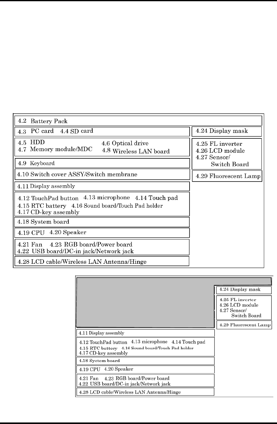
4.1 General 4 Replacement Procedures
4 Replacement Procedures
4.1 General
This section explains how to disassemble the computer and replace Field Replaceable Units
(FRUs). It may not be necessary to remove all the FRUs in order to replace one. The chart
below is a guide to which FRUs need to be removed in order to remove others. Always start
by removing the battery pack, next, optional items such as the optional PC card and optional
SD card, then follow the line on the chart to determine which FRU you must remove next in
order to repair the one you think is causing the computer to operate improperly. Refer to the
example at the bottom of the page.
How to See the Chart
Two examples of
referring to the chart are
shown below.
•Removing the Display
assembly
4.2 Battery to 4.10 Switch
cover ASSY/Switch
membrane must be
removed.
Satellite M30-35 Maintenance Manual (960-455) 4-1

4 Replacement Procedures 4.1 General
Safety Precautions
Before you begin disassembly, read the following safety precautions and observe them
carefully as you work.
DANGER: 1) Always use the genuine battery that is authorized by Toshiba or
compatible with the unit. Since other battery packs have different
specifications, they may be incompatible with the unit, and may burst or
explode.
Never heat or disassemble the battery pack, as that could cause leakage
of alkaline solution. Never throw the battery pack into a fire, as that
could cause the battery pack to explode.
2) The power supply, FL inverter and other components carry high
voltages. If you need to turn on the power of a partially disassembled
computer to check its operation, be very careful not to touch connectors
or components, in order to avoid the risk of electric shock.
Also, do not disassemble individual components in first-level
maintenance.
WARNING: 1) Turn off the power and disconnect the AC adaptor from the power
source, to avoid exposure to electric shock.
2) Batteries in the computer retain an electrical charge, so there is danger
of electrical shock even when the computer is disconnected from an AC
power source. Remove any metal jewelry or accessories such as
necklaces, bracelets or rings, in order to reduce the risk of electric
shock. Never work with wet or damp hands.
3) Be careful of edges and corners as these may cut.
CAUTION: 1) When you change a component, be sure the replacement component
meets the required specifications. Never use foreign parts, to avoid any
risk of damage to the computer.
2) To avoid any risk of short-circuit, fire or other internal damage, never
allow any metal objects such as screws or paper clips to fall into the
unit. Be sure to replace screws with the same size as those removed.
Make sure all screws are securely fastened. Loose screws can cause
short circuits, resulting in heat, smoke or fire.
3) Before lifting out an FRU or other component, make sure all cables to
the component have been disconnected, in order to reduce the risk of
accidental electric shock.
4) If you use AC power, be sure to use the cable that came with the
computer or one recommended by Toshiba.
5) Make sure that all replacement components meet the specifications for
the computer and that all cables and connectors are securely fastened, in
order to avoid the risk of electric shock.
6) Some parts inside the computer, such as the CPU and cooling module,
become very hot during operation. Conduct repair work after they have
cooled. Be careful around the CPU and cooling module to avoid burns.
4-2 Satellite M30-35 Maintenance Manual (960-455)

4.1 General 4 Replacement Procedures
Before You Begin
Look over the procedures in this section before you begin disassembling the computer.
Familiarize yourself with the disassembly and reassembly steps. Begin each procedure by
removing the AC adapter and the battery pack as instructed in this section:
1. Do not disassemble the computer unless it is operating abnormally.
2. Use only the correct and approved tools.
3. Make sure the working environment is free from the following elements whether you
are using or storing the computer.
• Dust and contaminates
• Static electricity
• Extreme heat, cold and humidity
4. Make sure the FRU you are replacing is causing the abnormal operation by
performing the necessary diagnostics tests described in this manual.
5. Do not perform any operations that are not necessary and use only the described
procedures for disassembling and installing FRUs in the computer.
6. After removing parts from the computer, place them in a safe place away from the
computer so they will not be damaged and will not interfere with your work.
7. You will remove and replace many screws when you disassemble the computer.
When you remove screws, make sure they are placed in a safe place and identified
with the correct parts.
8. When assembling the computer make sure you use the correct screws to secure the
various pieces in place. Screw sizes are listed in their corresponding figures.
9. The computer contains many sharp edges and corners, so be careful not to injure
yourself.
10. After you have replaced an FRU, make sure the computer is functioning properly by
performing the appropriate test on the FRU you have fixed or replaced.
Satellite M30-35 Maintenance Manual (960-455) 4-3

4 Replacement Procedures 4.1 General
Disassembly Procedures
The computer has two basic types of cable connectors:
• Pressure Plate Connectors
• Coaxial Cable Connectors
• Normal Pin Connectors
To disconnect a Pressure Plate connector, lift up the tabs on either side of the connector’s
plastic pressure plate and slide the cable out of the connector. To connect the cable to a
Pressure Plate connector, make sure the pressure plate is fully lifted and slide the cable into
the connector. Secure the cable in place by pushing the sides of the pressure plate down so
the plate is flush with the sides of the connector. Gently pull on the cable to make sure the
cable is secure. If you pull out the connector, connect it again making sure the connector’s
pressure plate is fully lifted when you insert the cable.
Coaxial cables should be disconnected with an antenna coaxial disconnector.
Standard pin connectors are used with all other cables. These connectors can be connected
and disconnected by simply pulling them apart or pushing them together.
Assembly Procedures
After you have disassembled the computer and fixed or repaired the problem that was
causing the computer to operate abnormally, you will need to reassemble the computer.
Install all the removed FRUs following the steps described in the corresponding sections in
this chapter.
While assembling the computer, remember the following general points:
• Take your time, making sure you follow the instructions closely. Most problems
arise when you get in a hurry assembling the computer.
• Make sure all cables and connectors are securely fastened.
• Before securing the FRU or other parts, make sure that screws or the FRU will
pinch no cables.
• Check that all latches are closed securely in place.
• Make sure all the correct screws are used to secure all FRUs. Using the wrong
screw can either damage the threads on the screw or the head of the screw and
may prevent proper seating of an FRU.
After installing an FRU in the computer, confirm that the FRU and the computer are
functioning properly.
4-4 Satellite M30-35 Maintenance Manual (960-455)

4.1 General 4 Replacement Procedures
Tools and Equipment
The use of Electrostatic Discharge (ESD) equipment is very important for your safety and the
safety of those around you. Proper use of these devices will increase the success rate of your
repairs and lower the cost for damaged or destroyed parts. The following equipment is
necessary to disassemble and reassemble the computer:
• One M2 point size 0 Phillips screwdriver to remove and replace screws.
• One M2.5/M3 point size 1 Phillips screwdriver to remove and replace screws.
• One 4 mm flat-blade screwdriver.
• Tweezers, to lift out screws that you cannot grasp with your fingers.
• ESD mats for the floor and the table you are working on.
• An ESD wrist strap or heel grounder.
• Anti-static carpeting or flooring.
• Air ionizers in highly static sensitive areas.
• Antenna coaxial cable disconnector
Satellite M30-35 Maintenance Manual (960-455) 4-5

4 Replacement Procedures 4.1 General
Screw Tightening Torque
When you fasten screws, be sure to follow the torque list below.
CAUTION: Overtightening can damage components and screws; undertightening can
result in electrical shorts or other damage if screws or components come
loose.
NOTE: Toshiba recommends that you use an electric screwdriver for quick and easy
operations.
• M2 0.17 N·m (1.7 kgf·cm)
• M2.5 0.30 N·m (3.0 kgf·cm)
• M3 0.57 N·m (5.6 kgf·cm)
NOTE: The computer contains several flat head screws. These screws have less contact
area with the screwdriver, so be careful to press firmly enough to prevent the
screwdriver from slipping out and damaging the screw head.
4-6 Satellite M30-35 Maintenance Manual (960-455)

4.1 General 4 Replacement Procedures
Color of Screw Shaft
To avoid mistakes on the screw length, screw shafts are colored as follows:
Even number length screw: brown
Odd number length screw: white
Special length screw: blue
Screws whose lengths are indicated to one or more decimal places such as 2.5 mm or
2.8 mm.
Marking of Screws on the Computer Body
To make maintenance of the computer easier, markings of the kinds of the screws including
the types and lengths of the screws are indicated on the computer body.
Kind of screws Symbol
BIND screw B
FLAT HEAD screw F
SUPER FLAT HEAD screw S
TAPPING screw T
Other screws U
(Unique screws, STUD, etc.)
Examples:
6 mm BIND screw B6
12 mm BIND screw B12
5 mm FLAT HEAD screw F5
(Indicates the screwed length in round number regardless the length of the stud.)
Satellite M30-35 Maintenance Manual (960-455) 4-7
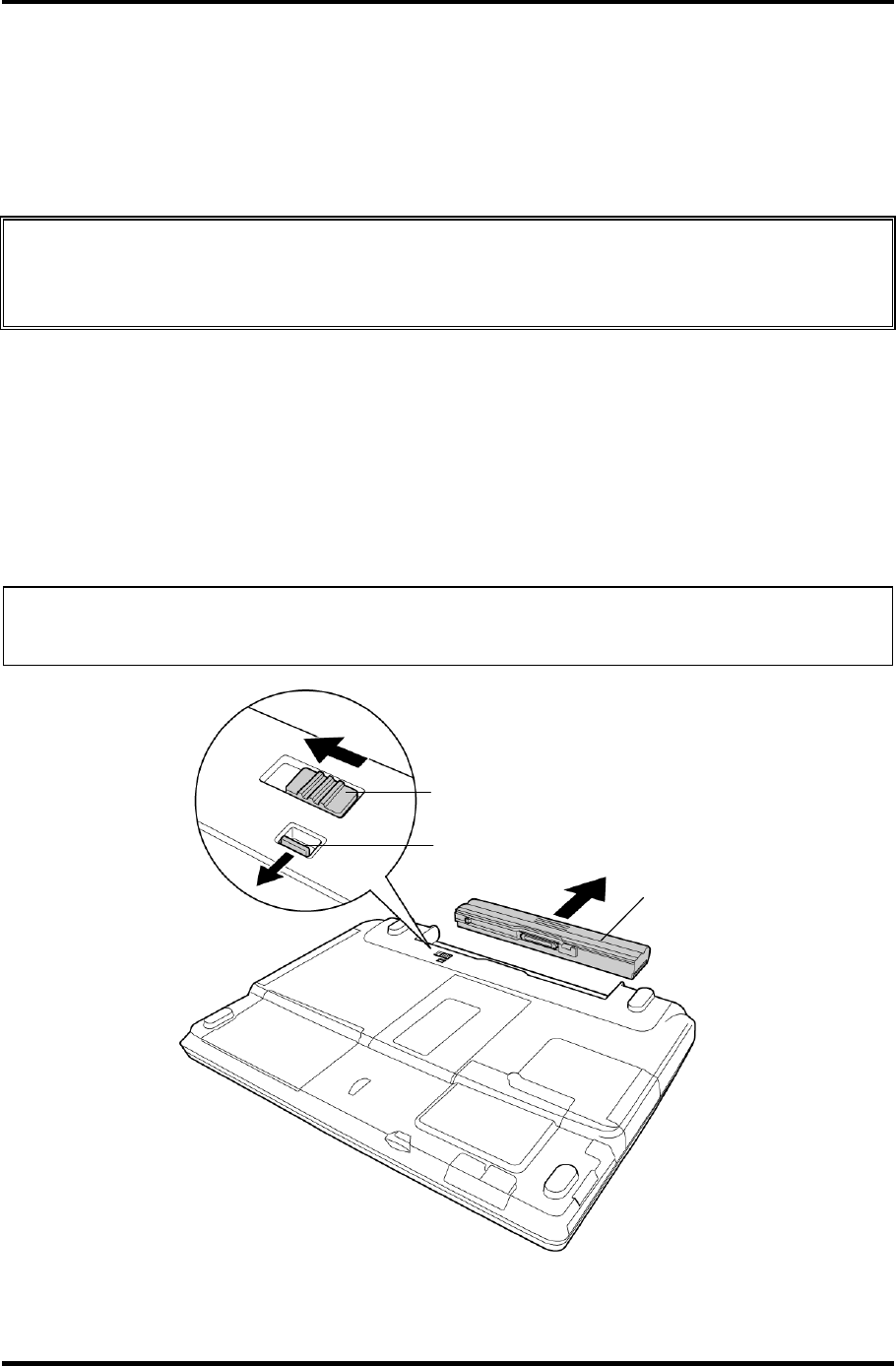
4 Replacement Procedures 4.2 Battery Pack
4.2 Battery Pack
Removing the Battery Pack
To remove the battery pack, follow the steps below and refer to figure 4-1.
CAUTION: When handling battery packs, be careful not to short circuit the terminals.
Also do not drop, hit or apply impact; do not scratch, break, twist or bend
the battery pack.
1. Turn off the computer.
2. Disconnect the AC cable and other external devices from the computer.
3. Turn the computer face down.
4. Release the battery lock while sliding the battery latch, pull out the battery pack to
the arrow direction in the figure below.
NOTE: For environmental reasons, do not throw away a spent battery pack. Collect the
spent battery packs.
Battery latch
Battery lock
Battery
Figure 4-1 Removing the Battery pack
4-8 Satellite M30-35 Maintenance Manual (960-455)

4.2 Battery Pack 4 Replacement Procedures
Installing the Battery Pack
To install the battery pack, follow the steps below and refer to figure 4-1.
CAUTION: The battery pack is a lithium ion battery, which can explode if not properly
replaced, used, handled or disposed of. For environmental reasons, collect
the spent battery packs. Use only batteries recommended by Toshiba as
replacements.
NOTE: Check the battery's terminals visually. If they are dirty, wipe them clean with a
dry cloth.
1. Push the battery pack into the battery slot. Make sure the battery pack is installed
securely.
2. Slide the battery lock into the lock position.
Satellite M30-35 Maintenance Manual (960-455) 4-9
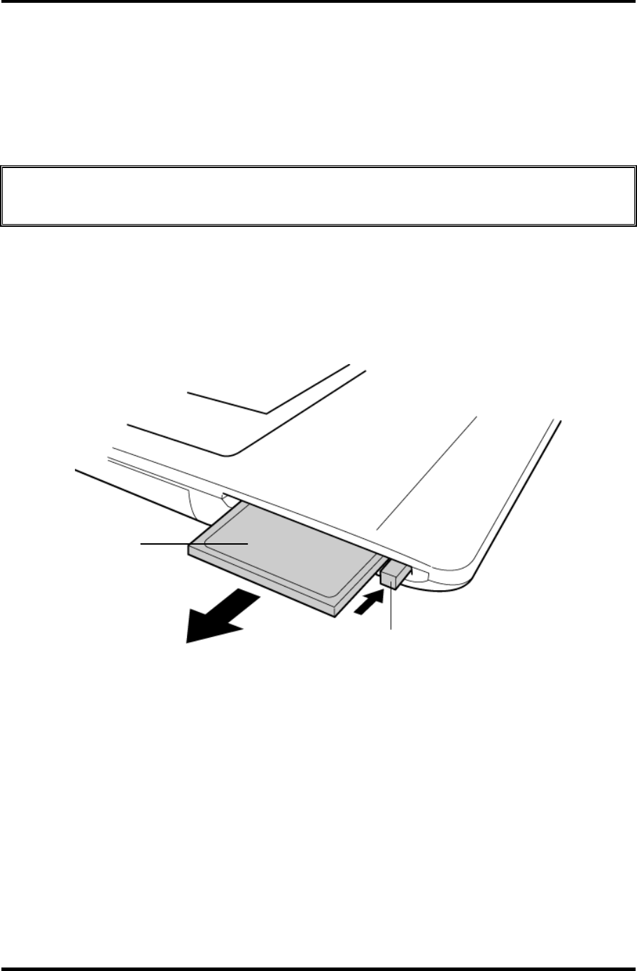
4 Replacement Procedures 4.3 PC Card
4.3 PC Card
Removing the PC Card
To remove the PC card, follow the steps below and refer to figure 4-2.
CAUTION: Before you remove a PC card, refer to the card's documentation and your
operating system documentation for proper procedures and precautions.
1. Turn the computer face up.
2. Push the eject button. It will pop out when you release it. Then press once more the
eject button to eject the PC card.
3. Grasp the PC card and pull it out.
PC card
Eject button
Figure 4-2 Removing the PC card
4-10 Satellite M30-35 Maintenance Manual (960-455)

4.3 PC Card 4 Replacement Procedures
Installing the PC Card
To install the PC card, follow the steps below and refer to figure 4-2.
1. Make sure the eject button does not stick out.
2. Insert the PC card and press it until it is securely connected.
Satellite M30-35 Maintenance Manual (960-455) 4-11
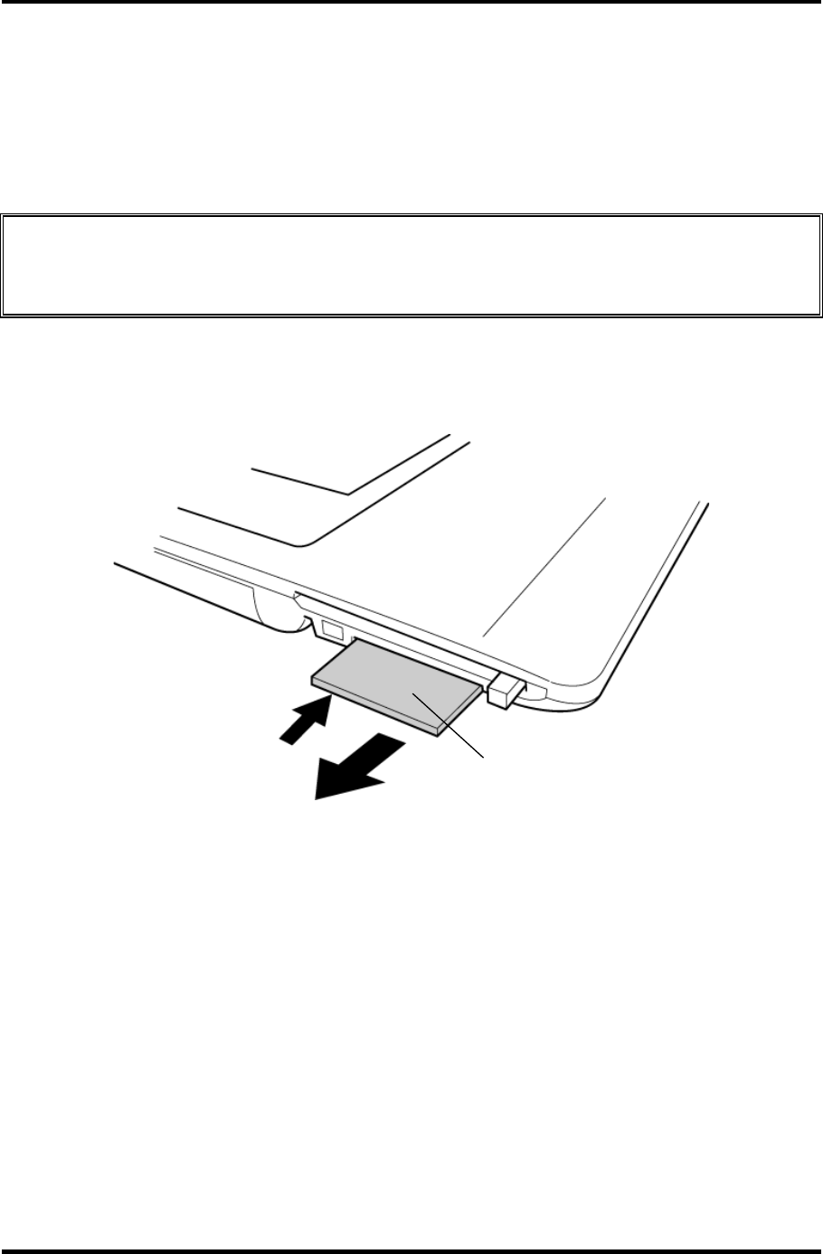
4 Replacement Procedures 4.4 SD Card
4.4 SD Card
Removing the SD Card
To remove the SD card, follow the steps below and refer to figure 4-3.
CAUTION: Before you remove the SD card, refer to the card's documentation and to
your operating system documentation for proper procedures and
precautions.
1. Turn the computer face up.
2. Push the SD card. It will pop out partly when you release, so pull out the card.
SD card
Figure 4-3 Removing the SD card
Installing the SD Card
To install the SD card, follow the steps below and refer to figure 4-3.
1. Insert the SD card and press it until it is securely connected.
4-12 Satellite M30-35 Maintenance Manual (960-455)
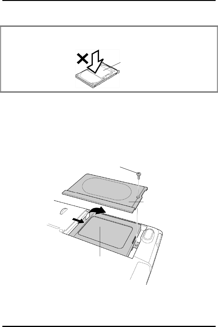
4.5 HDD 4 Replacement Procedures
4.5 HDD
CAUTION: When handling the HDD, do not press the top surface as shown by the arrow.
Hold it by the sides.
HDD
Removing the HDD
To remove the HDD, follow the steps below and refer to figures 4-4 and 4-5.
1. Turn the computer upside down.
2. Remove the following screw securing the HDD cover. Remove the HDD cover by
lifting up.
• M2.5×10B FLAT HEAD screw ×1
M2.5
×
10B FLAT HEAD
HDD cover
HDD pack
Figure 4-4 Removing the HDD cover
Satellite M30-35 Maintenance Manual (960-455) 4-13
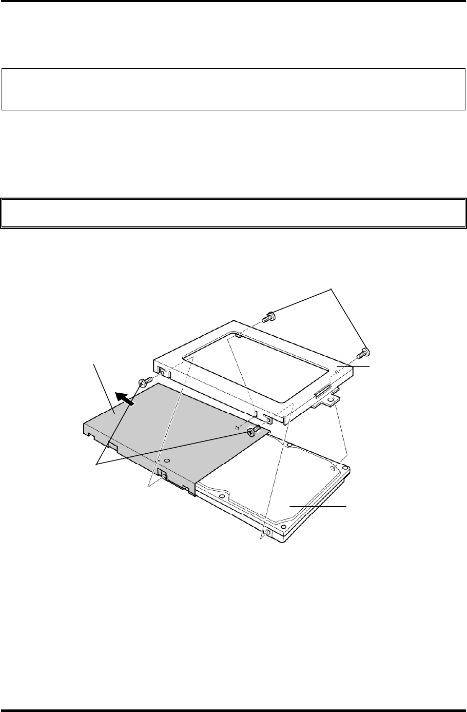
4 Replacement Procedures 4.5 HDD
3. Push the tab of the HDD pack to the direction of the arrow and remove the HDD
pack. Be careful not to damage the connector.
NOTE: The following steps describe how to disassemble the HDD pack; however, do not
disassemble if the HDD is working properly.
4. Remove the following screws.
• M3×4S FLAT HEAD screw ×4
5. Remove the HDD bracket.
CAUTION: Do not apply pressure to the top or bottom of the HDD.
6. Remove the HDD from the aluminum laminate.
HDD
HDD bracket
M3
×
4S FLAT HEAD
M3×4S FLAT HEAD
Aluminum laminate
Figure 4-5 Removing the HDD bracket and HDD
4-14 Satellite M30-35 Maintenance Manual (960-455)
4.5 HDD 4 Replacement Procedures
Installing the HDD
To install the HDD, follow the steps below and refer to figures 4-4 and 4-5.
CAUTION: Do not hold the HDD by its top and bottom flat surfaces. It may damage the
HDD.
1. Install the HDD to the aluminum laminate.
2. Place the HDD in the bracket.
3. Secure the HDD to the HDD bracket with the following screws.
• M3×4S FLAT HEAD screw ×4
CAUTION: Do not apply pressure to the middle of the HDD pack. It may damage the
HDD pack. Hold the HDD pack by its corners.
4. Hold the HDD pack and place it in the slot. Slide the HDD pack to the connector of
the computer to connect. Press to ensure a firm connection.
5. Seat the HDD cover and secure it with the following screw.
• M2.5×10B FLAT HEAD screw ×1
Satellite M30-35 Maintenance Manual (960-455) 4-15
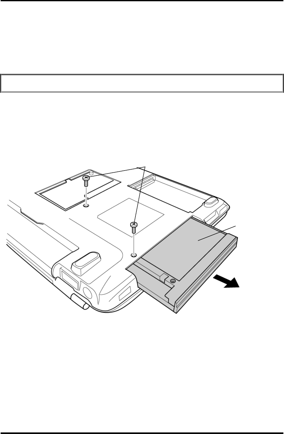
4 Replacement Procedures 4.6 Optical Drive
4.6 Optical Drive
Removing the Optical Drive
To remove the optical drive, follow the steps below and refer to figures 4-6 and 4-7.
CAUTION: Do not apply excessive force to the top of an optical drive.
1. Remove the following screws securing the optical drive.
• M2.5×4B FLAT HEAD screw ×2
2. Slide the optical drive outward to disconnect it from the connector PJ1820 on the
system board.
M2.5
×
4B FLAT HEAD
Optical drive
Figure 4-6 Removing the optical drive
4-16 Satellite M30-35 Maintenance Manual (960-455)
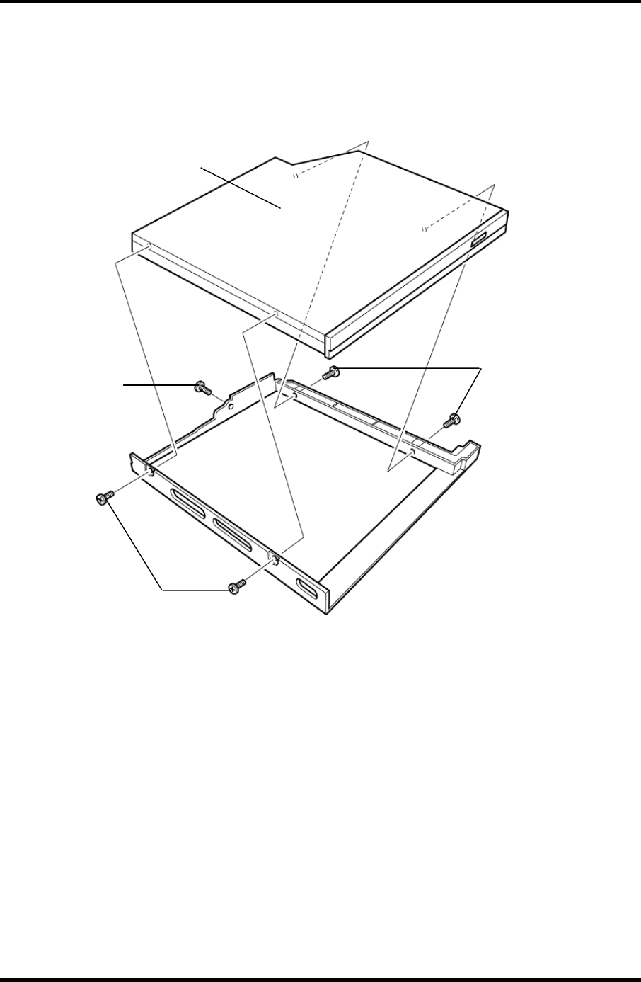
4.6 Optical Drive 4 Replacement Procedures
3. Remove the following screws securing the plastic frame.
• M2×3C S-FLAT HEAD screw ×4
• Stepping screw ×1
Optical Drive
Plastic frame
M2×3CS-FLAT HEAD
M2×3CS-FLAT HEAD
Stepping screw
Figure 4-7 Disassembling the optical drivel
Satellite M30-35 Maintenance Manual (960-455) 4-17

4 Replacement Procedures 4.6 Optical Drive
Installing the Optical drive
To install the optical drive, follow the steps below and refer to figures 4-6 and 4-7.
1. Seat the plastic frame on the side of the optical drive, and secure it with the
following screws.
• M2×3C S-FLAT HEAD screw ×4
• Stepping screw ×1
2. Slide the optical drive into the slot to connect it to the connector PJ1820 on the
system board.
3. Secure the optical drive with the following screws.
• M2.5×4B FLAT HEAD screw ×2
4-18 Satellite M30-35 Maintenance Manual (960-455)
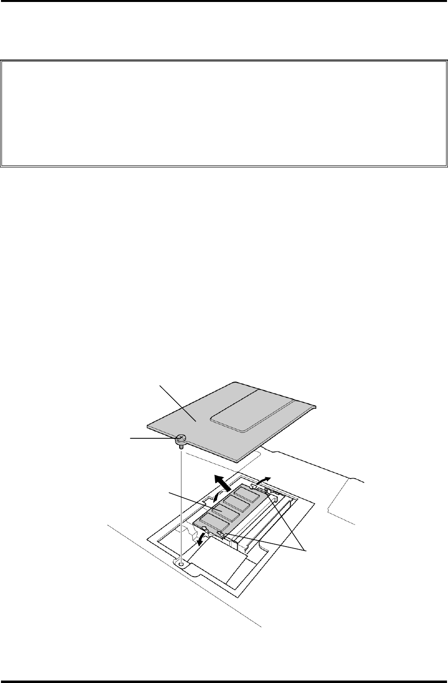
4.7 Memory module/ Modem Daughter Card 4 Replacement Procedures
4.7 Memory module/ Modem Daughter Card
CAUTION: The power of the computer must be turned off when you remove the memory
module. Removing a memory module with the power on risks damaging the
module or the computer itself.
Do not touch the memory module terminals. Any dirt on the terminals may
cause memory access problems.
Never press hard or bend the memory module.
4.7.1 Memory module
Removing the memory module
To remove a memory module, confirm that the computer is in boot mode. Then perform the
following procedures (See Figure 4-8).
1. Turn the computer upside down.
2. Loosen the screw (e-ring) fixing the memory slot cover.
3. Remove the memory slot cover.
4. Open the left and right latches and remove the memory module.
Memory module
Screw
Latches
Memory slot cove
r
Figure 4-8 Removing the memory module
Satellite M30-35 Maintenance Manual (960-455) 4-19

4 Replacement Procedures 4.7 Memory module/ Modem Daughter Card
Installing the memory module
To install the memory module, confirm that the computer is in boot mode. Then follow the
steps below and refer to figures 4-8.
1. Insert the memory module into the connector of the computer slantwise (terminal
side first) and press it to connect firmly.
CAUTION: The power must be turned off when you insert the memory module. Inserting
a memory module with the power on might damage the module or the
computer itself.
Never press hard or bend the memory module.
2. Install the memory slot cover and secure it with the screw (e-ring).
3. When the power of the computer is turned on, the computer checks automatically the
memory size. Confirm that the new memory is detected correctly.
4. If the memory is not detected, check that it is connected correctly.
4-20 Satellite M30-35 Maintenance Manual (960-455)
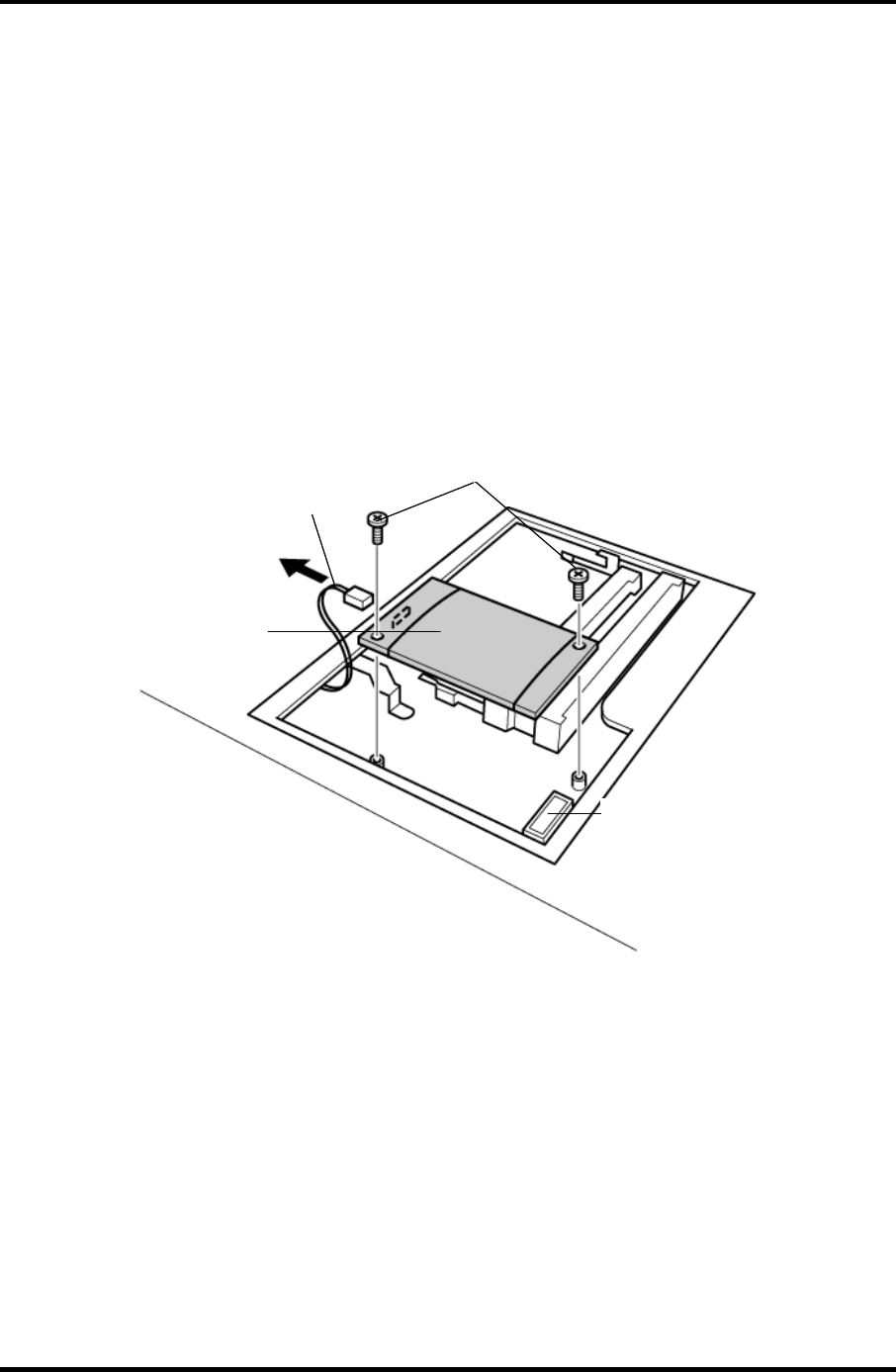
4.7 Memory module/ Modem Daughter Card 4 Replacement Procedures
4.7.2 Modem Daughter Card
Removing the Modem Daughter Card
To remove the modem daughter card, follow the steps below and refer to figure 4-9.
1. Remove the following screws securing the modem daughter card.
• M2×4B BIND screw ×2
2. Lift up the modem daughter card to disconnect it from the connector PJ3000 on the
system board.
4. Disconnect the modem cable from CN1 on the modem daughter card.
PJ3000
MDC
Modem cable
M2
×
4B BIND
Figure 4-9 Removing the modem daughter card
Satellite M30-35 Maintenance Manual (960-455) 4-21

4 Replacement Procedures 4.7 Memory module/ Modem Daughter Card
Installing the Modem Daughter Card
To install the modem daughter card, follow the steps below and refer to figures 4-9.
1. Connect the modem cable to CN1 on the modem daughter card.
2. Connect the modem daughter card to the connector PJ3000 on the system board.
CAUTION: Be careful not to damage the card or connector.
3. Secure the modem daughter card with the following screws.
• M2×4B BIND screw ×2
4. Place the memory slot cover and secure it with the screw (e-ring).
4-22 Satellite M30-35 Maintenance Manual (960-455)
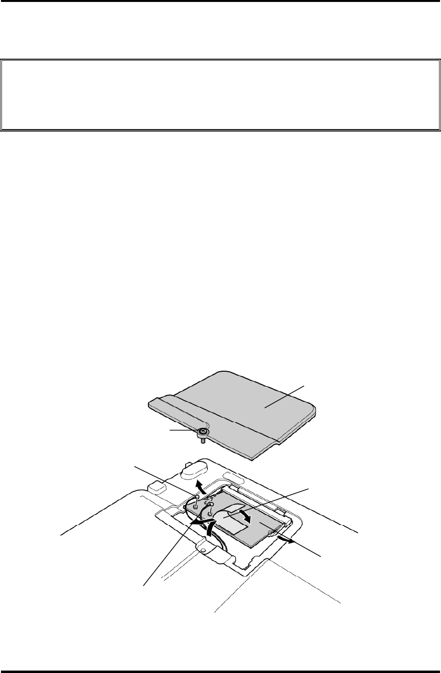
4.8 Wireless LAN board 4 Replacement Procedures
4.8 Wireless LAN board
CAUTION: The power must be turned off when you remove the wireless LAN board.
Removing the wireless LAN board with the power on risks damaging the
card or the computer itself.
Never press hard or bend the wireless LAN board.
Removing the wireless LAN board
To remove the wireless LAN board, follow the steps below and refer to figure 4-10.
1. Turn the computer upside down.
2. Loosen the screw fixing the wireless LAN board cover.
• M2×4B BIND screw ×1
Or
• M2×4 LH STICK screw ×1
3. Peel off the glass tape and disconnect the two wireless LAN antenna cables (black
and white) from the wireless LAN board.
4. Open the left and right latches holding the wireless LAN board and remove it.
Wireless LAN board
Antenna cable (black)
Antenna cable (white)
Wireless LAN board cover
Glass tape
M2×4B BIND or M2×4 LH STICK
Figure 4-10 Removing the wireless LAN board
Satellite M30-35 Maintenance Manual (960-455) 4-23

4 Replacement Procedures 4.8 Wireless LAN board
4-24 Satellite M30-35 Maintenance Manual (960-455)
Installing the wireless LAN board
To install the wireless LAN board, follow the steps below and refer to figure 4-10.
1. Insert the wireless LAN board terminals slantwise into the connector on the
computer and press the wireless LAN board until it is securely in place.
2. Connect the wireless LAN cables (black and white) to the terminals on the wireless
LAN board and fix them with the glass tape.
3. Place the wireless LAN board cover and secure it with the following screw.
• M2×4B BIND screw ×1
Or
• M2×4 LH STICK screw ×1
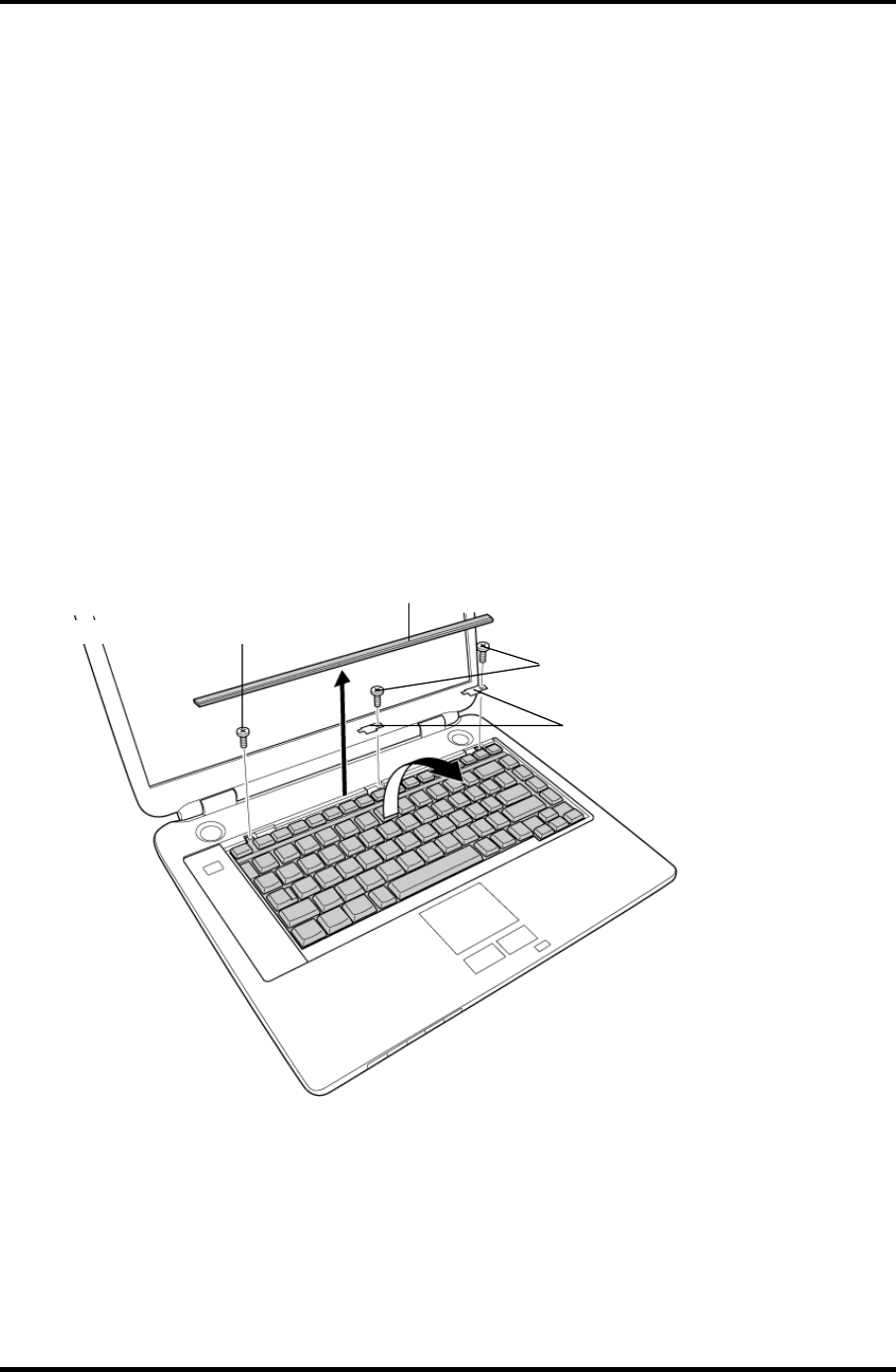
4 Replacement Procedures 4.9 Keyboard
4 Replacement Procedures
4.9 Keyboard
Removing the Keyboard
To remove the keyboard, follow the steps below and refer to figures 4-11 to 4-12.
1. Turn the computer face up and open the display panel.
2. Insert your finger into the latches between the keyboard brace and the computer, and
lift up the keyboard brace to unlatch and remove it.
3. Remove the following screw securing the keyboard and keyboard hold plates. Then
remove the keyboard hold plate.
• M2×4B BIND screw ×1
Or
• M2×4 LH STICK screw ×1
Keyboard brace
Keyboard hold plate
M2
×
4B BIND or M2×4 LH STICK
M2×4B BIND or M2
×
4 LH STICK
Figure 4-11 Removing the keyboard brace and keyboard hold plate
4-26 Satellite M30-35 Maintenance Manual (960-455)
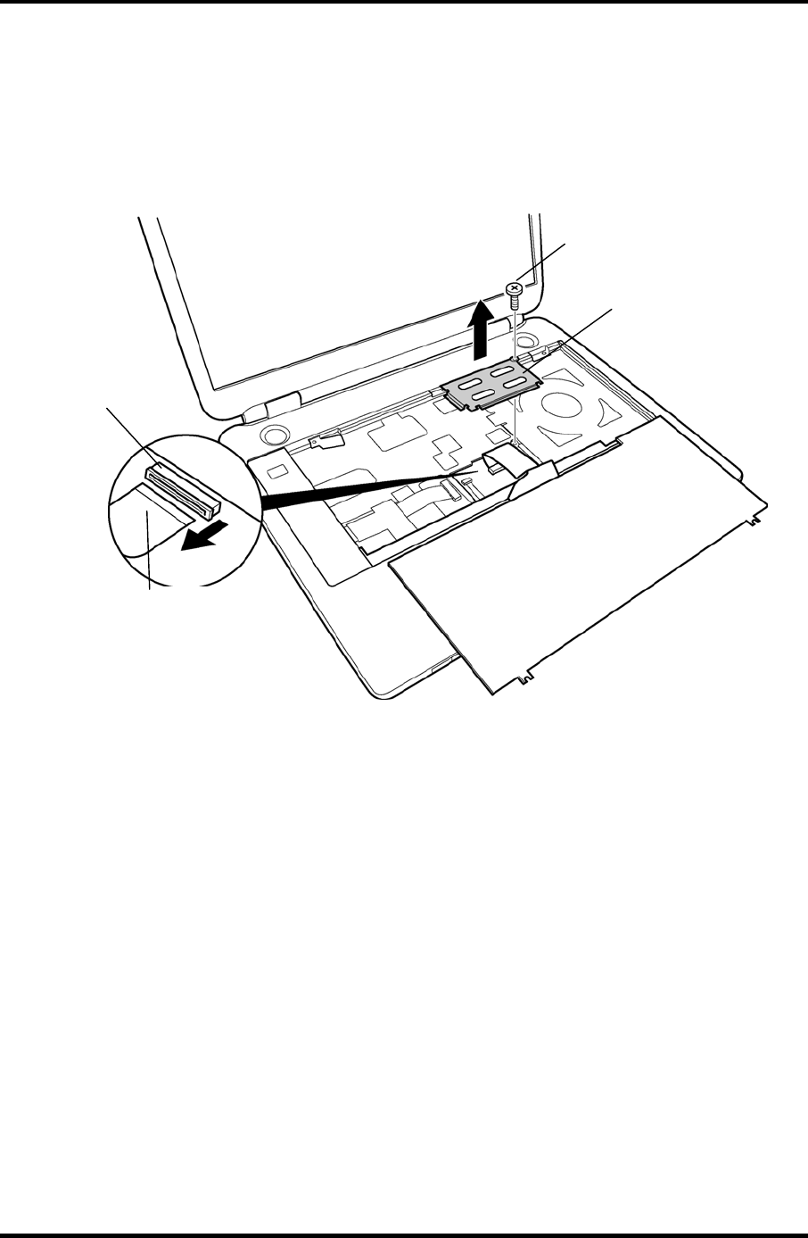
4.9 Keyboard 4 Replacement Procedures
4. Lift the upper side of the keyboard out and turn it’s face down on the palm rest.
5. Remove the following screw securing the keyboard support plate and remove the
keyboard support plate.
• M2.5×8B FLAT HEAD screw ×1
M2.5×8B FLAT HEAD
PJ3200
Keyboard support
plate
Keyboard cable
Figure 4-12 Removing the keyboard support plate
7. Disconnect the keyboard cable from the connector PJ3200 on the system board, and
remove the keyboard.
Satellite M30-35 Maintenance Manual (960-455) 4-27

4 Replacement Procedures 4.9 Keyboard
Installing the Keyboard
To install the keyboard, follow the steps below and refer to figures 4-11 to 4-12.
1. Place the keyboard face down on the palm rest.
2. Connect the keyboard cable to the connector PJ3200 on the system board.
3. Place the keyboard support plate and secure it with the following screw.
• M2.5×8B FLAT HEAD screw ×1
4. Turn the keyboard face up and put it on the computer. Make sure that there is no gap
between the keyboard and the computer.
5. Place the keyboard hold plates on the keyboard. Then secure the keyboard hold
plates and the keyboard with the following screws.
• M2×4B BIND screw ×2
Or
• M2×4 LH STICK screw ×2
6. Install the keyboard brace by pressing it from the topside.
4-28 Satellite M30-35 Maintenance Manual (960-455)
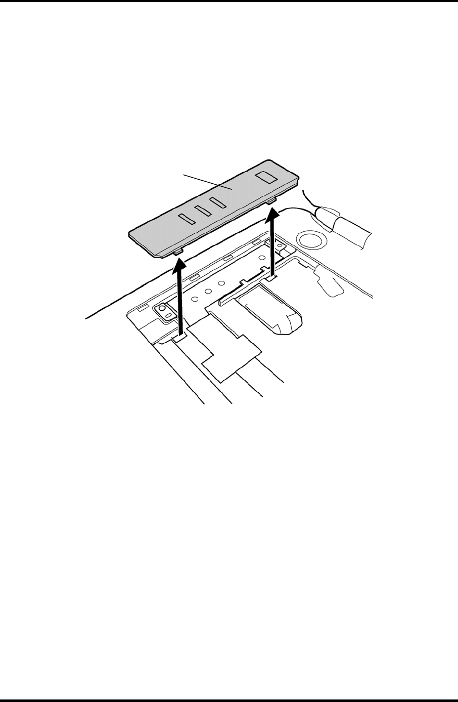
4.10 Switch cover ASSY/Switch membrane 4 Replacement Procedures
4.10 Switch cover ASSY/Switch membrane
Removing the Switch cover ASSY/Switch membrane
To remove the Switch cover ASSY/Switch membrane, follow the steps below and refer to
figure 4-13 and 4-14.
1. Remove the switch cover ASSY by lifting the left side up, while releasing the latches.
Switch cover ASSY
Figure 4-13 Removing the switch cover ASSY
Satellite M30-35 Maintenance Manual (960-455) 4-29
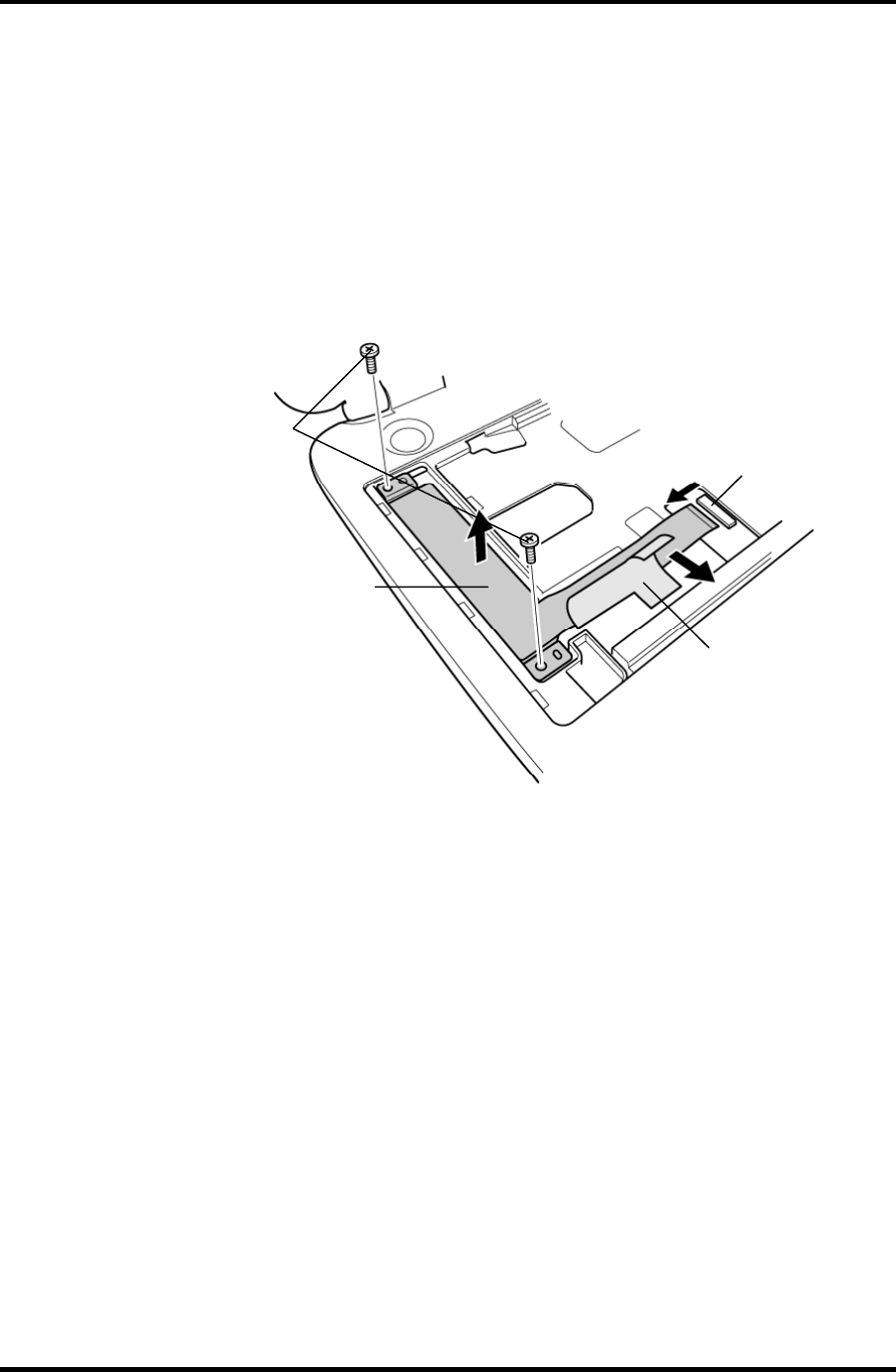
4 Replacement Procedures 4.10 Switch cover ASSY/Switch membrane
2. Pull up the insulator.
3. Disconnect the switch membrane cable from the connector PJ7001 on the system
board.
4. Remove the following screws fixing the switch membrane.
• M2.5×4B FLAT HEAD screw ×2
5. Remove the switch membrane by lifting up the left side of the switch membrane.
Switch membrane
M2.5×4B FLAT HEAD
Insulator
PJ7001
Figure 4-14 Removing the switch membrane
4-30 Satellite M30-35 Maintenance Manual (960-455)

4.10 Switch cover ASSY/Switch membrane 4 Replacement Procedures
Installing the Switch cover ASSY/Switch membrane
To install the Switch cover ASSY/Switch membrane, follow the steps below and refer to
figure 4-13 and 4-14.
1. Place the switch membrane with the right side under the guides and secure it with
the following screws.
• M2.5×4B FLAT HEAD screw ×2
2. Connect the switch membrane cable to the connector PJ7001 on the system board.
3. Stick the insulator to fix the switch membrane.
4. Install the switch cover ASSY and engage the right-side latches.
Satellite M30-35 Maintenance Manual (960-455) 4-31
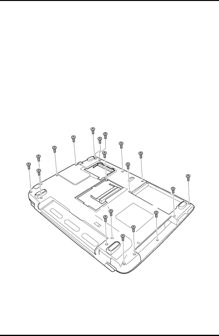
4 Replacement Procedures 4.11 Display Assembly
4.11 Display Assembly
Removing the Display Assembly
To remove the display assembly, follow the steps below and refer to figures
4-15 to 4-17.
1. Turn the computer face down, and remove the following screws.
• M2.5×16B FLAT HEAD screw ×8 (“16” in the figure below)
• M2.5×10B FLAT HEAD screw ×8 (“10” in the figure below)
• M2×6B BIND screw ×2 (“6” in the figure below)
• M2×4B S-FLAT HEAD screw ×1 (“4” in the figure below)
16
16
16
16
16
16
16
16
4
10
6
10
10
10
10
10
10
6
10
Figure 4-15 Removing the display assembly (1)
4-32 Satellite M30-35 Maintenance Manual (960-455)
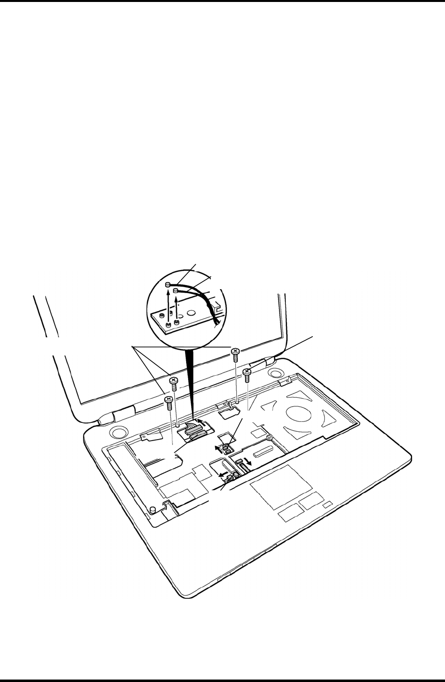
4.11 Display Assembly 4 Replacement Procedures
2. Turn the computer face up and open the display panel.
3. Remove the following screws securing the display assembly.
• M2.5×6B FLAT HEAD screw ×3
• M2.5×8B FLAT HEAD screw ×1
4. Disconnect the LCD cable from the connector PJ5600 on the system board.
5. Disconnect the two wireless LAN cables from the connectors, white and black on the
power board.
6. Disconnect the internal microphone cable from the connector PJ6001 on the system
board.
7. Disconnect the panel switch cable from the connector PJ7004 on the system board.
M2.5×6B FLAT HEAD
PJ5600
PJ6001
PJ7004
Wireless LAN cable (black)
Wireless LAN cable (white)
M2.5×8B FLAT HEAD
Figure 4-16 Removing the display assembly (2)
Satellite M30-35 Maintenance Manual (960-455) 4-33
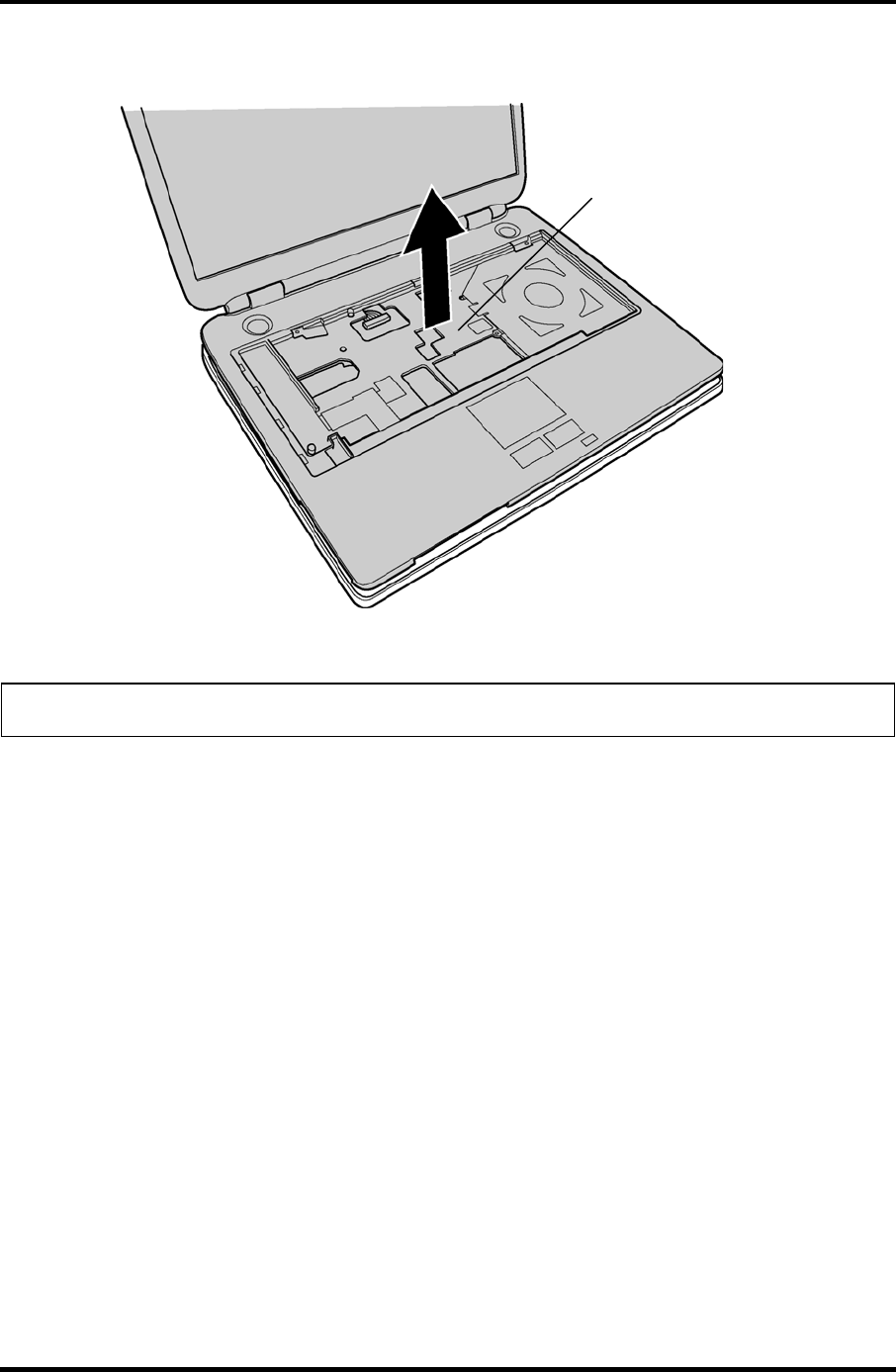
4 Replacement Procedures 4.11 Display Assembly
8. Remove the display assembly from the base assembly.
Display assembly
Figure 4-17 Removing the display assembly (3)
NOTE: When removing the display assembly, be careful not to damage any cables.
4-34 Satellite M30-35 Maintenance Manual (960-455)

4.11 Display Assembly 4 Replacement Procedures
Installing the Display Assembly
To install the display assembly, follow the steps below and refer to figures 4-15 to 4-17.
1. Install the display assembly on the base assembly.
NOTE: When installing the display assembly, be careful not to pinch or damage any
cables.
2. Press along the edges of the display assembly to secure the latches.
3. Connect the panel switch cable to the connector PJ7004 on the system board.
4. Connect the internal microphone cable to the connector PJ6001 on the system
board.
5. Connect the LCD cable to the connector PJ5600 on the system board.
6. Connect the two wireless LAN cables to the connectors, white and black on the
power board.
7. Secure the display assembly with the following screws.
• M2.5×6B FLAT HEAD screw ×3
• M2.5×8B FLAT HEAD screw ×1
8. Turn the computer face down and secure the display assembly with the following
screws.
• M2.5×16B FLAT HEAD screw ×8
• M2.5×10B FLAT HEAD screw ×8
• M2×6B BIND screw ×2
• M2×4B S-FLAT HEAD screw ×1
Satellite M30-35 Maintenance Manual (960-455) 4-35
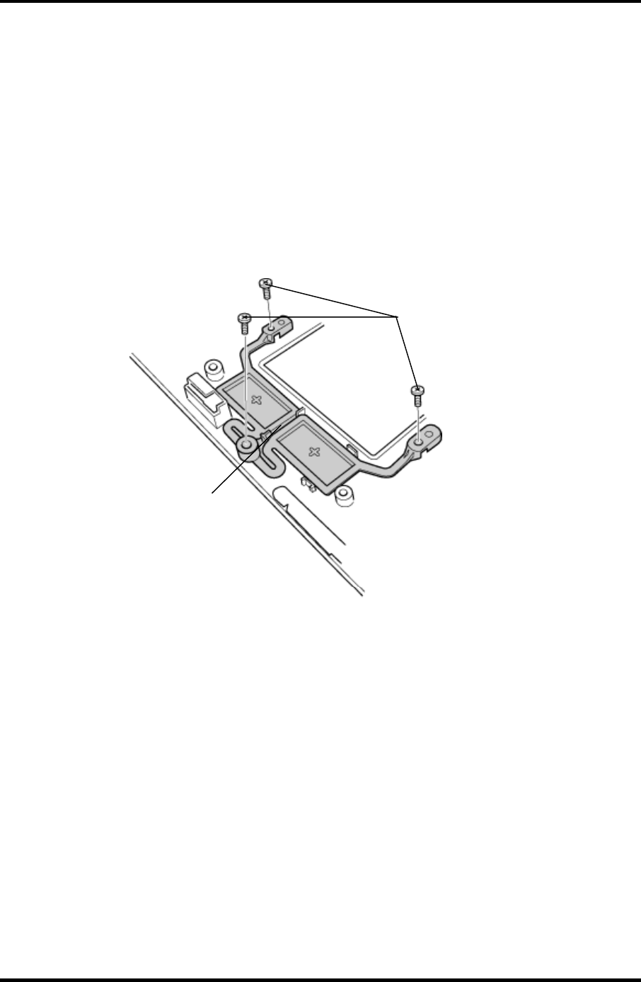
4 Replacement Procedures 4.12 Touch Pad Button
4.12 Touch Pad Button
Removing the Touch Pad Button
To remove the touch pad button, follow the steps below and refer to figure 4-18.
1. Remove the following screws fixing the touch pad button.
• M2.5×4 Tapping screw ×3
2. Remove the touch pad button.
M2.5
×
4 Tapping
T
ouch pad button
Figure 4-18 Removing the touch pad button
Installing the Touch Pad Button
To installing the touch pad button, follow the steps below and refer to figure 4-18.
1. Install the touch pad button and fix it with the following screws.
• M2.5×4 Tapping screw ×3
4-36 Satellite M30-35 Maintenance Manual (960-455)
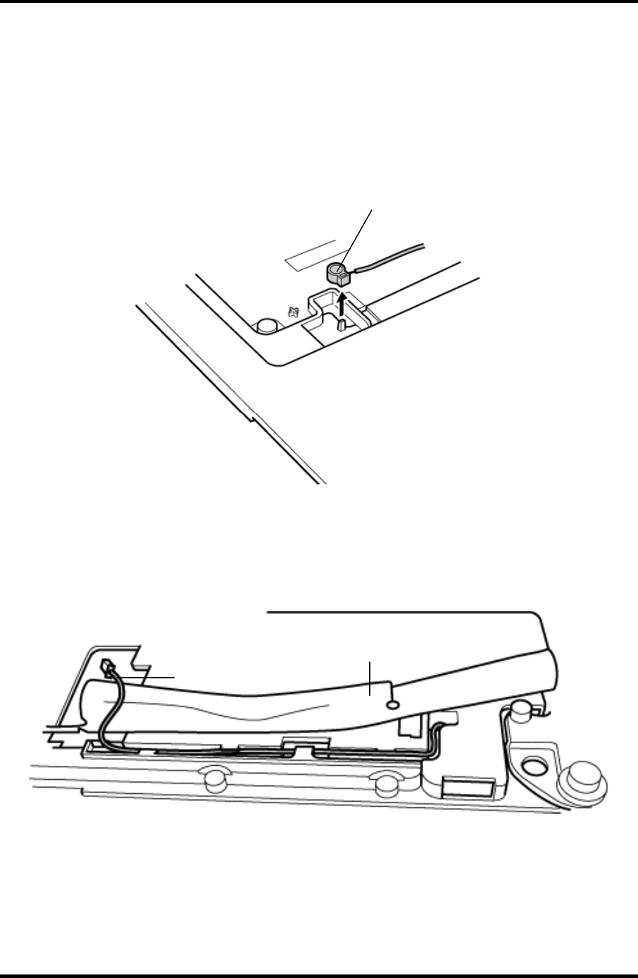
4.13 Microphone 4 Replacement Procedures
4.13 Microphone
Removing the Microphone
To remove the Microphone, follow the steps below and refer to figures 4-19 and 20.
1. Remove the microphone from the guide.
Microphone
Figure 4-19 Removing the microphone
2. Peel the insulator on the back and remove the microphone cable from the guide.
3. Remove the microphone (with cable) through the hole to the front.
Microphone cable
Insulator
Figure 4-20 Removing the microphone cable
Satellite M30-35 Maintenance Manual (960-455) 4-37

4 Replacement Procedures 4.13 Microphone
Installing the Microphone
To install the Microphone, follow the steps below and refer to figures 4-19 and 20.
1. Pass the microphone cable from the front to the back.
2. Set the microphone, putting the hole in the guide.
3. Pass the microphone cable through the slot with guides.
4-38 Satellite M30-35 Maintenance Manual (960-455)
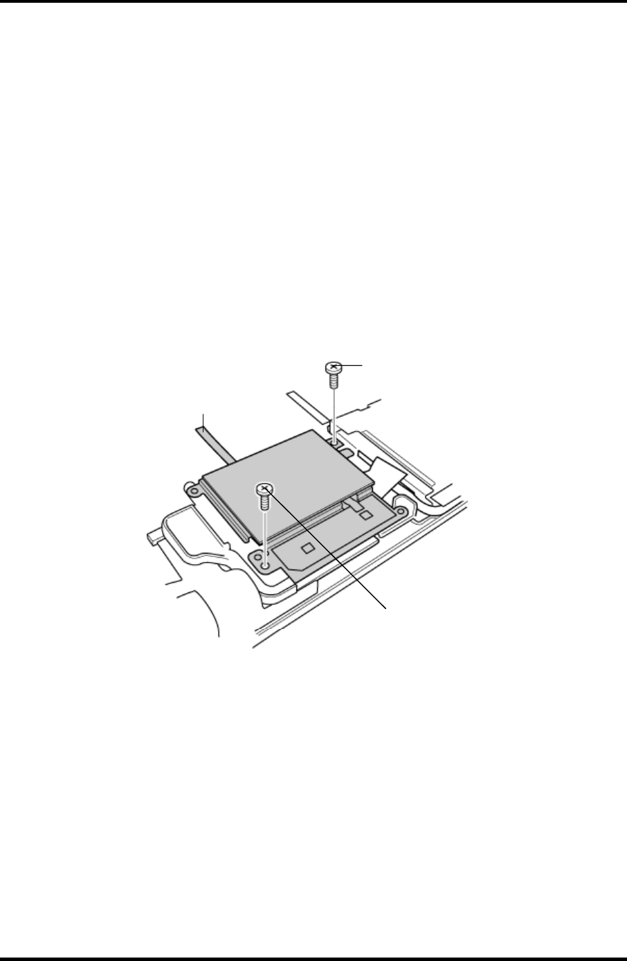
4.14 Touch Pad 4 Replacement Procedures
4.14 Touch Pad
Removing the Touch Pad
To remove the touch pad, follow the steps below and refer to figures 4-21.
1. Disconnect the touch pad flexible cable from the connector PJ3201 on the system
board.
2. Remove the following screws securing the touch pad.
• M2.5×8B FLAT HEAD screw ×1
• M2.5×4B FLAT HEAD screw ×1
3. Remove the touch pad.
T
ouch pad flexible cable
M2.5
×
8B FLAT HEAD
M2.5
×
4B FLAT HEAD
Figure 4-21 Removing the touch pad
4. Disconnect the touch pad flexible cable from the connector on the touch pad.
Satellite M30-35 Maintenance Manual (960-455) 4-39

4 Replacement Procedures 4.14 Touch Pad
Installing the Touch Pad
To install the touch pad, follow the steps below and refer to figures 4-21.
1. Connect the touch pad flexible cable to the connector on the touch pad.
2. Install the touch pad and secure it with the following screws.
• M2.5×8B FLAT HEAD screw ×1
• M2.5×4B FLAT HEAD screw ×1
3. Connect the touch pad flexible cable to the connector PJ3201 on the system board.
4-40 Satellite M30-35 Maintenance Manual (960-455)

4.15 RTC Battery 4 Replacement Procedures
4.15 RTC Battery
WARNING: When replacing the RTC battery, be sure to use genuine batteries or
replacement batteries authorized by Toshiba. Installing the wrong battery
could cause a battery explosion or other damage.
If the RTC battery is found abnormal, it must not be installed. Replace it
with a new battery, and dispose of the old one according to the local
regulations.
Check for any of the following signs of damage:
1) Electrolyte leakage
• Corrosion (greenish color) on the battery connector or cable
• Corrosion on the computer's battery connector
• White powder on any part of the battery
• White powder in the battery tray
• Clear liquid on the battery
• Clear liquid in the battery tray
• Clear liquid on any board near the battery
2) Damage to the connection cable
3) Damage to the connector housing
If any powder or liquid is found in or around the battery tray, clean it. Be
careful not to let any leaked material contact your eyes or mouth. Do not
inhale fumes from leaked material.
If leaked material contacts your skin, eyes or mouth, wash the affected area
thoroughly with clean water.
Satellite M30-35 Maintenance Manual (960-455) 4-41
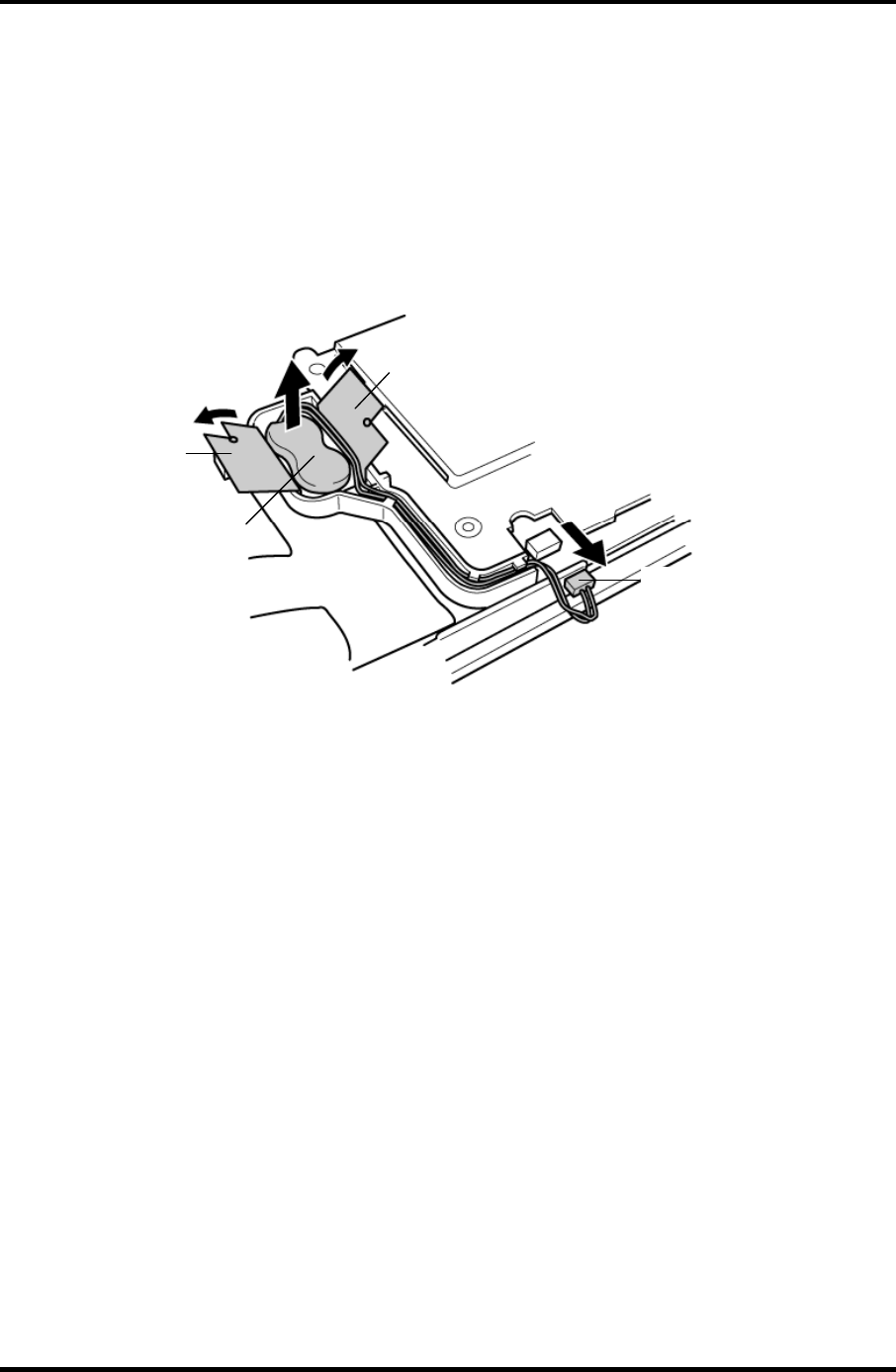
4 Replacement Procedures 4.15 RTC Battery
Removing the RTC Battery
To remove the RTC battery, follow the steps below and refer to figure 4-22.
1. Peel off the insulator.
2. Disconnect the RTC battery cable from the connector PJ8490 on the system board.
3. Remove the RTC battery.
Insulator
RTC battery
RTC battery cable
Insulator
Figure 4-22 Removing the RTC battery
Installing the RTC Battery
To install the RTC battery, follow the steps below and refer to figure 4-22.
1. Place the RTC battery into the slot.
2. Pass the RTC battery cable through the battery guide and connect the RTC battery
cable to the connector PJ8490 on the system board.
3. Fix the RTC battery with the insulator.
4-42 Satellite M30-35 Maintenance Manual (960-455)
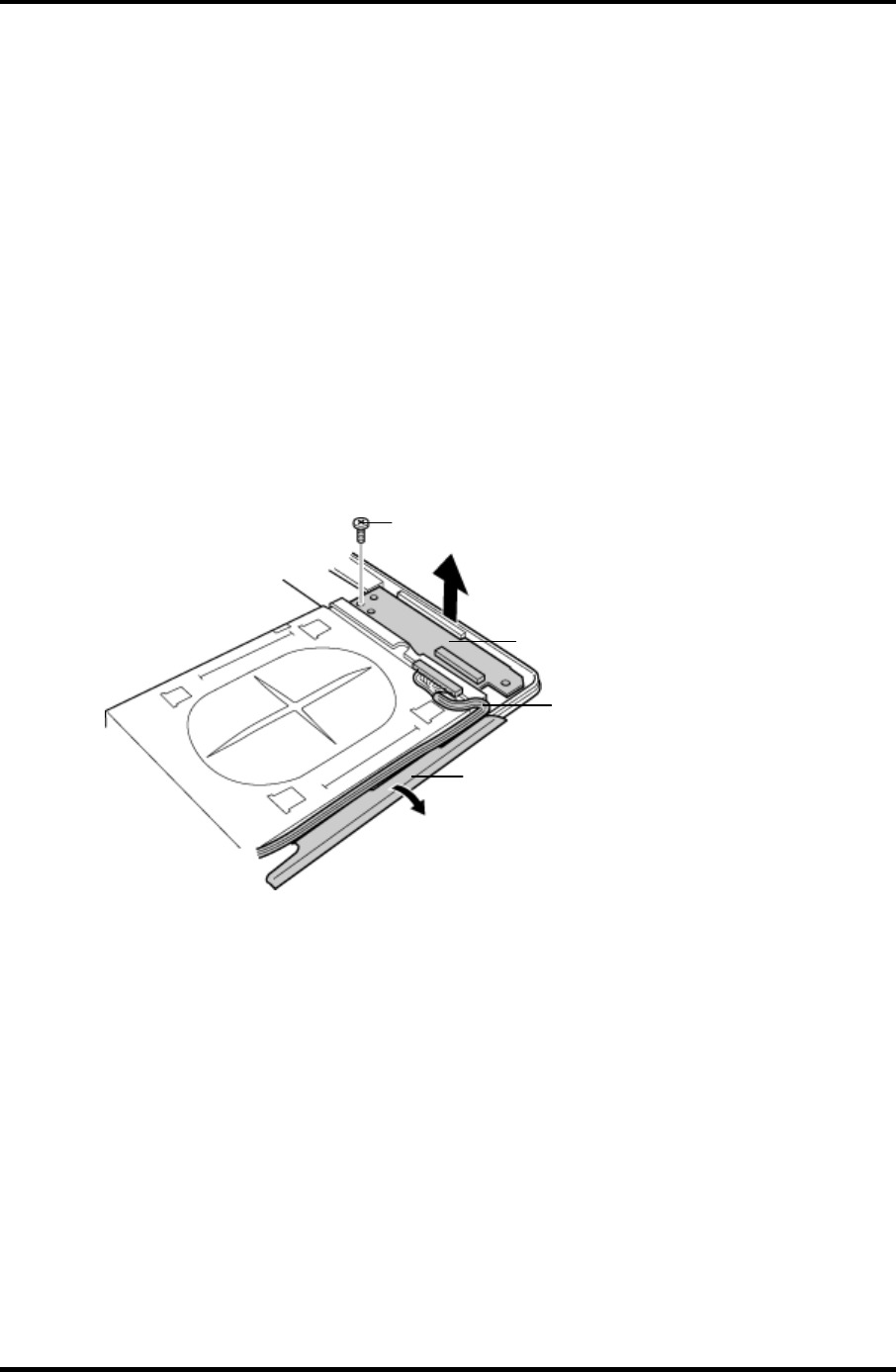
4.16 Sound Board/Touch Pad holder 4 Replacement Procedures
4.16 Sound Board/Touch Pad holder
4.16.1 Sound Board
Removing the Sound Board
To remove the sound board, follow the steps below and refer to figure 4-23.
1. Remove the following screw and the sound board.
• M2.5×6B FLAT HEAD screw ×1
2. Disconnect the sound board I/F cable from the connector on the sound board.
3. Peel the insulator.
Sound board
M2.5
×
6B FLAT HEAD
Insulator
Sound board I/F cable
Figure 4-23 Removing the sound board
Satellite M30-35 Maintenance Manual (960-455) 4-43

4 Replacement Procedures 4.16 Sound Board/Touch Pad holder
Installing the Sound Board
To install the sound board, follow the steps below and refer to figure 4-23.
1. Connect the sound board I/F cable to the connector on the sound board and secure it
with the insulator.
2. Install the sound board from the side with jacks and secure it with the following
screw.
• M2.5×6B FLAT HEAD screw ×1
4-44 Satellite M30-35 Maintenance Manual (960-455)
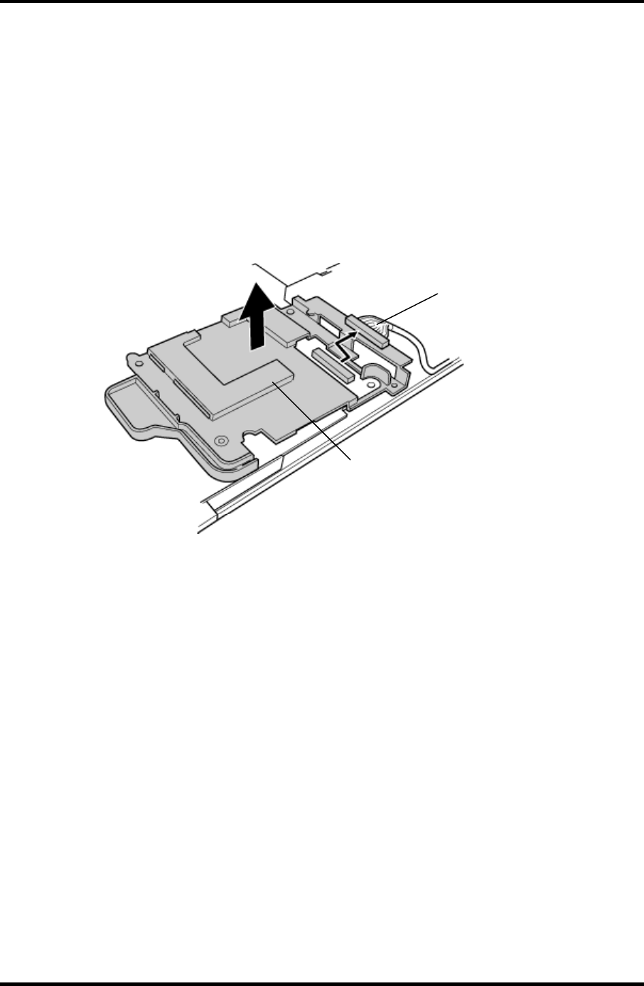
4.16 Sound Board/Touch Pad holder 4 Replacement Procedures
4.16.2 Touch Pad holder
Removing the Touch Pad holder
To remove the touch pad holder, follow the steps below and refer to figures 4-24.
1. Disconnect the sound board I/F cable from the connector PJ7002 on the system
board.
2. Remove the touch pad holder from the system board.
Sound board I/F cable
T
ouch pad holde
r
Figure 4-24 Removing the touch pad holder
Installing the Touch Pad holder
To install the touch pad holder, follow the steps below and refer to figures 4-24.
1. Install the touch pad holder on the system board.
2. Connect the sound board I/F cable to the connector PJ7002 on the system board.
Satellite M30-35 Maintenance Manual (960-455) 4-45
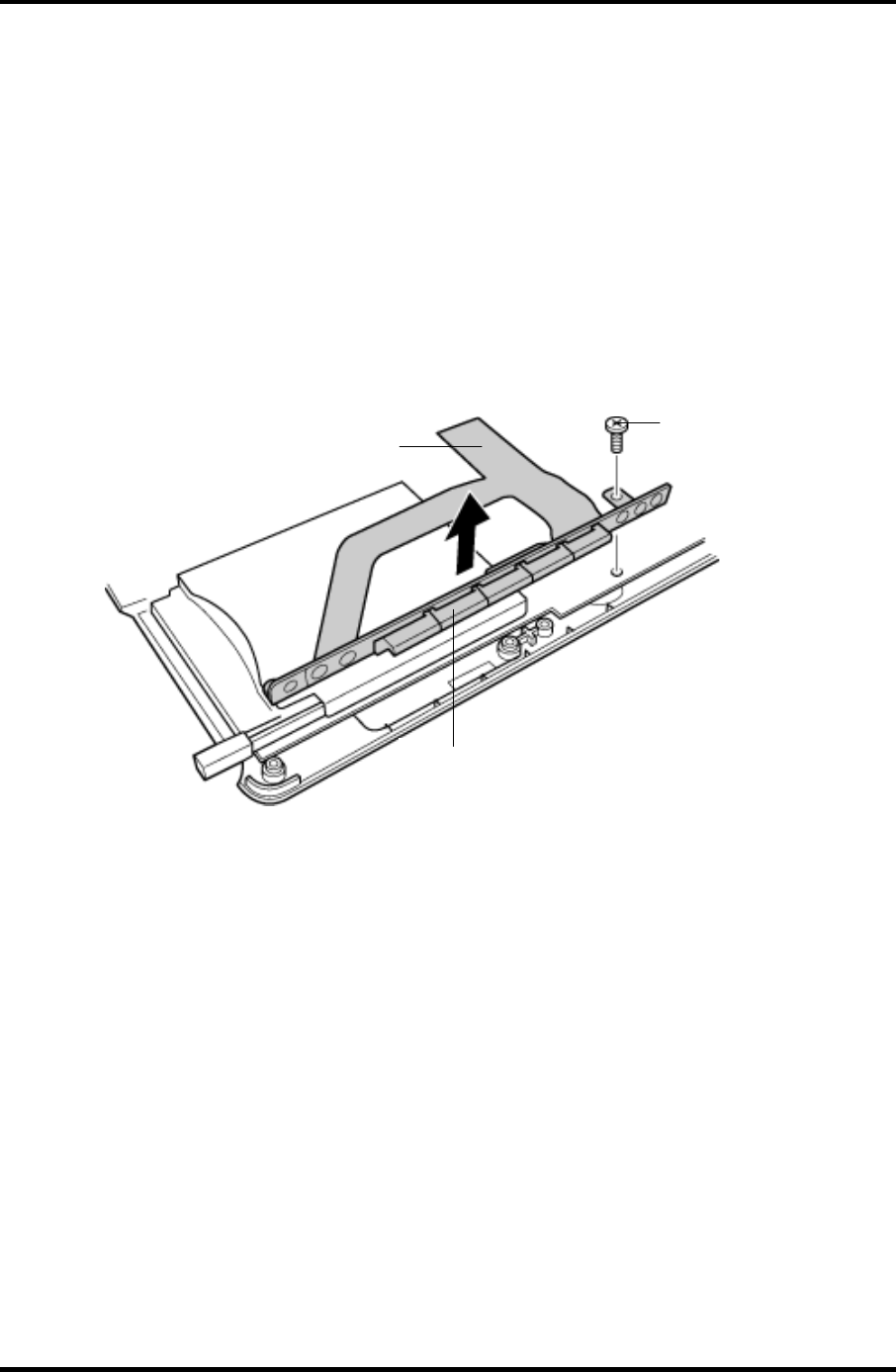
4 Replacement Procedures 4.17 CD-Key assembly
4.17 CD-Key assembly
Removing the CD-Key assembly
To remove the CD-key assembly, follow the steps below and refer to figures 4-25.
1. Disconnect the CD-key flexible cable from the connector PJ7000 on the system
board.
2. Remove the following screw and the CD-key assembly.
• M2×4B BIND screw ×1
M2
×
4
B
BIND
CD-key flexible cable
CD-key
Figure 4-25 Removing the CD-key assembly
Installing the CD-Key assembly
To install the CD-key assembly, follow the steps below and refer to figures 4-25.
1. Place the CD-key assembly and secure it with the following screw.
• M2×4B BIND screw ×1
2. Connect the CD-key flexible cable to the connector PJ7000 on the system board.
4-46 Satellite M30-35 Maintenance Manual (960-455)
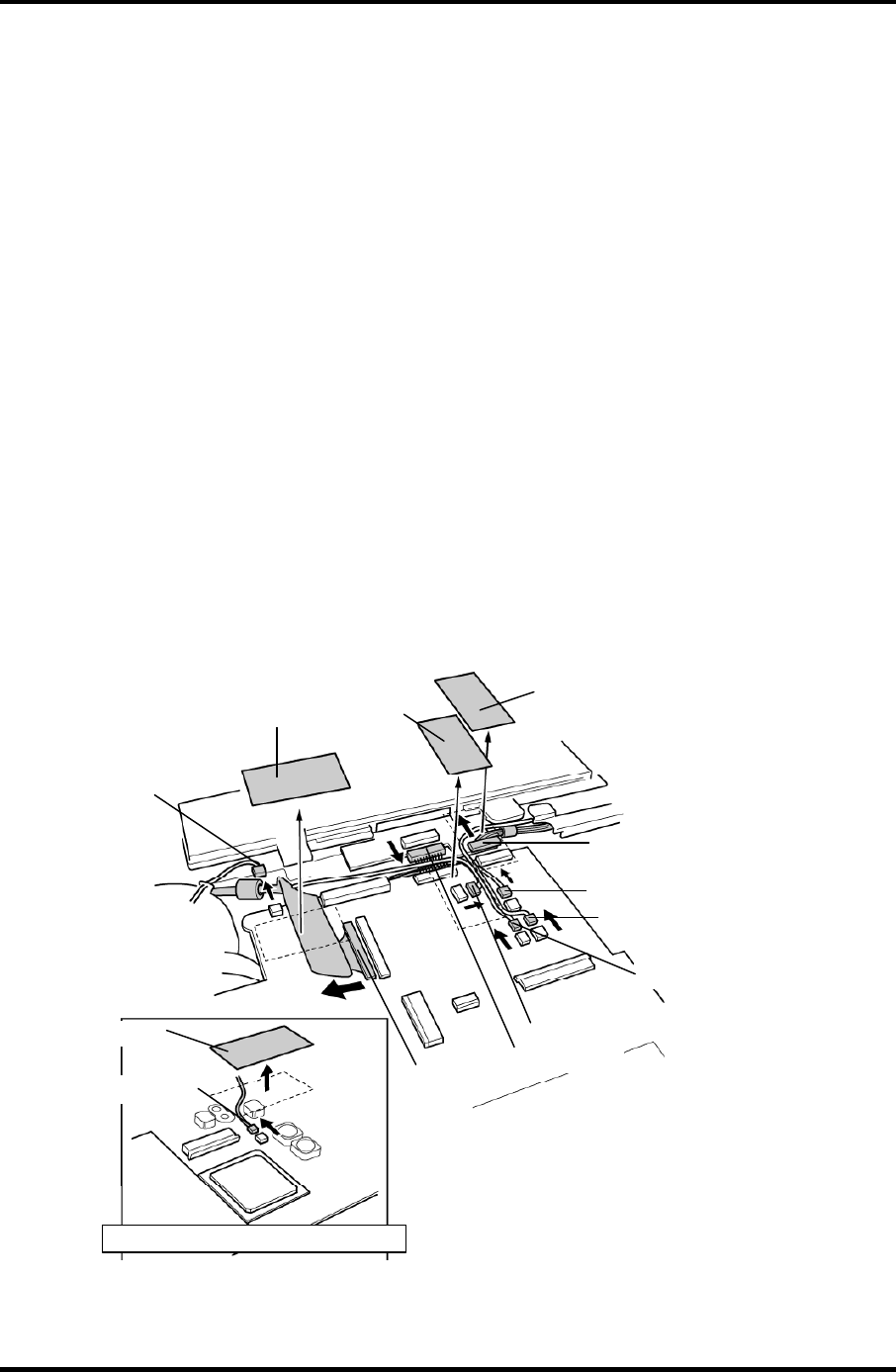
4.18 System Board 4 Replacement Procedures
4.18 System Board
Removing the System Board
To remove the system board, follow the steps below and refer to figures 4-26 and 4-27.
1. Peel off the glass tape and disconnect the RGB cable from the connector PJ5621 on
the system board.
2. Disconnect the speaker cables from the connectors PJ6003 (red) and PJ6004 (blue)
on the system board.
3. Disconnect the USB cable from the connector PJ7003 on the system board.
4. Peel off the glass tapes and disconnect the battery cable from the connector PJ8810
and the network cable from the connector PJ4100on the system board.
5. Disconnect the fan cable from the connector PJ8770 on the system board and the
power cable from the connector CN3 on the power board.
6. Peel off the glass tape and disconnect the USB cable from the connector PJ7005 on
the system board.(VRAM64 only)
Glass tape Glass tape
RGB cable
Speaker cable (blue)
Speaker cable (red)
USB cable
Fan cable
Battery cable
Network cable
Power cable
Glass tape
Glass tape
USB cable
*Case of the VRAM64 only
Figure 4-26 Removing the system board (1)
Satellite M30-35 Maintenance Manual (960-455) 4-47
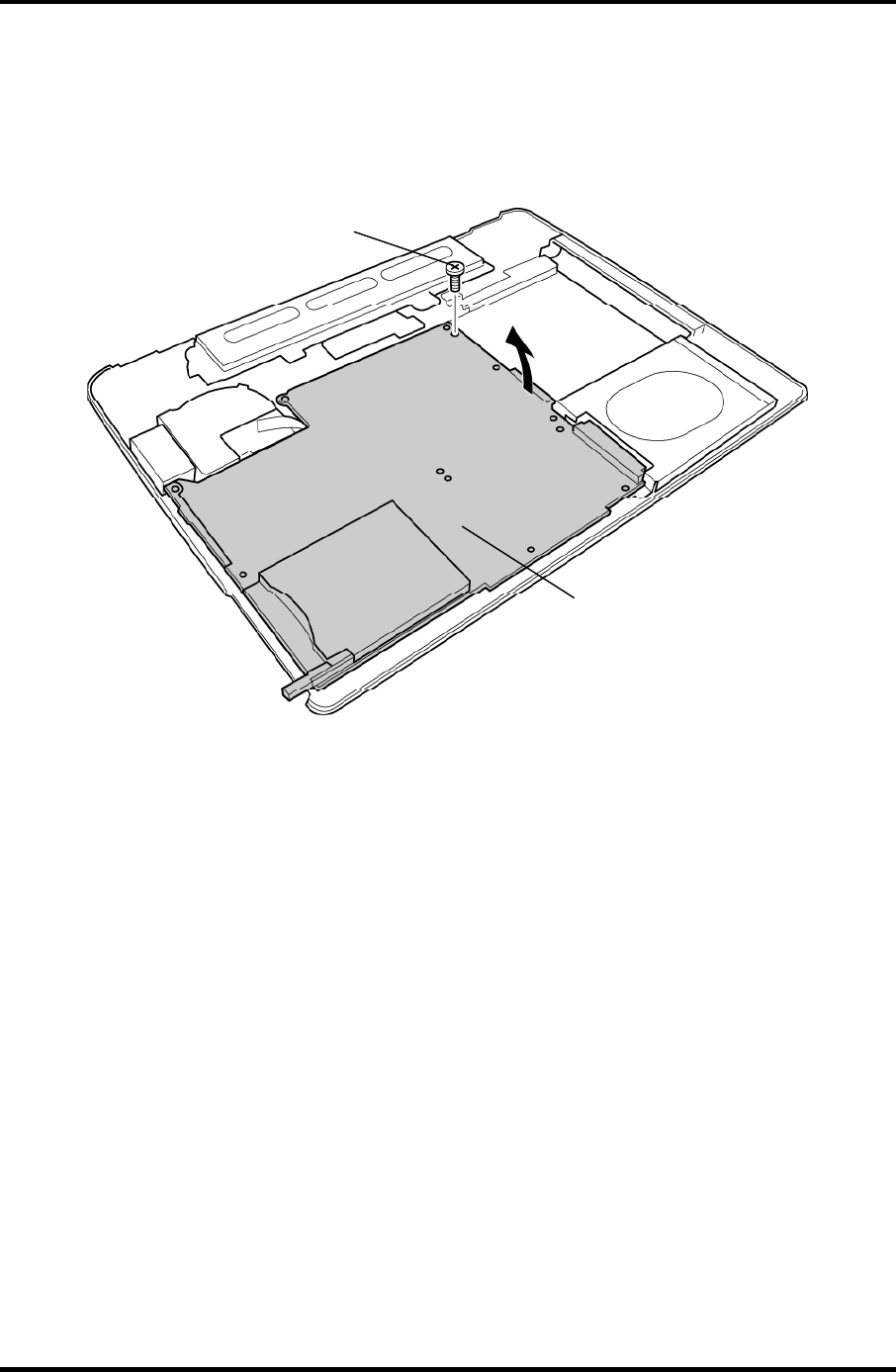
4 Replacement Procedures 4.18 System Board
7. Remove the following screws securing the system board.
• M2.5×6B FLAT HEAD screw ×1
8. Lift up the right side of the system board and remove it.
System board
M2.5×6B FLAT HEAD
Figure 4-27 Removing the system board (2)
4-48 Satellite M30-35 Maintenance Manual (960-455)

4.18 System Board 4 Replacement Procedures
Satellite M30-35 Maintenance Manual (960-455) 4-49
Installing the System Board
To install the system board, follow the steps below and refer to figures 4-26 and 27.
1. Install the system board from the left side.
NOTE: When installing the system board, be careful not to pinch or damage the USB
cable, RGB cable, battery cable speaker cable, network cable, fan cable or
power cable.
2. Secure the system board with the following screws.
• M2.5×6B FLAT HEAD screw ×1
3. Connect the USB cable to the connector PJ7005 on the system board and stick the
glass tape.(VRAM64 only)
4. Connect the fan cable to the connector PJ8770 on the system board.
5. Connect the RGB cable to the connector PJ5621 on the system board and stick the
glass tape.
6. Connect the battery cable to the connector PJ8810 on the system board.
7. Connect the power cable to the connector CN3 on the power board.
8. Connect the USB cable to the connector PJ7003 on the system board.
9. Connect the speaker cables to the connectors PJ6003 and PJ6004 on the system
board.
10. Connect the network cable to the connector PJ4100 on the system board and stick
the glass tapes.

4 Replacement Procedures 4.19 CPU
4 Replacement Procedures
4.19 CPU
Removing the CPU
To remove the CPU, follow the steps below and refer to figures 4-28 and 4-29.
CAUTION: 1) The CPU can become very hot during operation. Be sure to let it cool
before starting repair work.
2) When you remove the CPU, wipe the grease off of the bottom of the fin
and top of the CPU. Apply new grease when installing.
1. Remove the following screws securing the CPU holder, in the reverse order of the
number marked on the holder.
• M2×4B BIND screw ×3
2. Remove the CPU holder.
3. Remove the fin.
4-50 Satellite M30-35 Maintenance Manual (960-455)
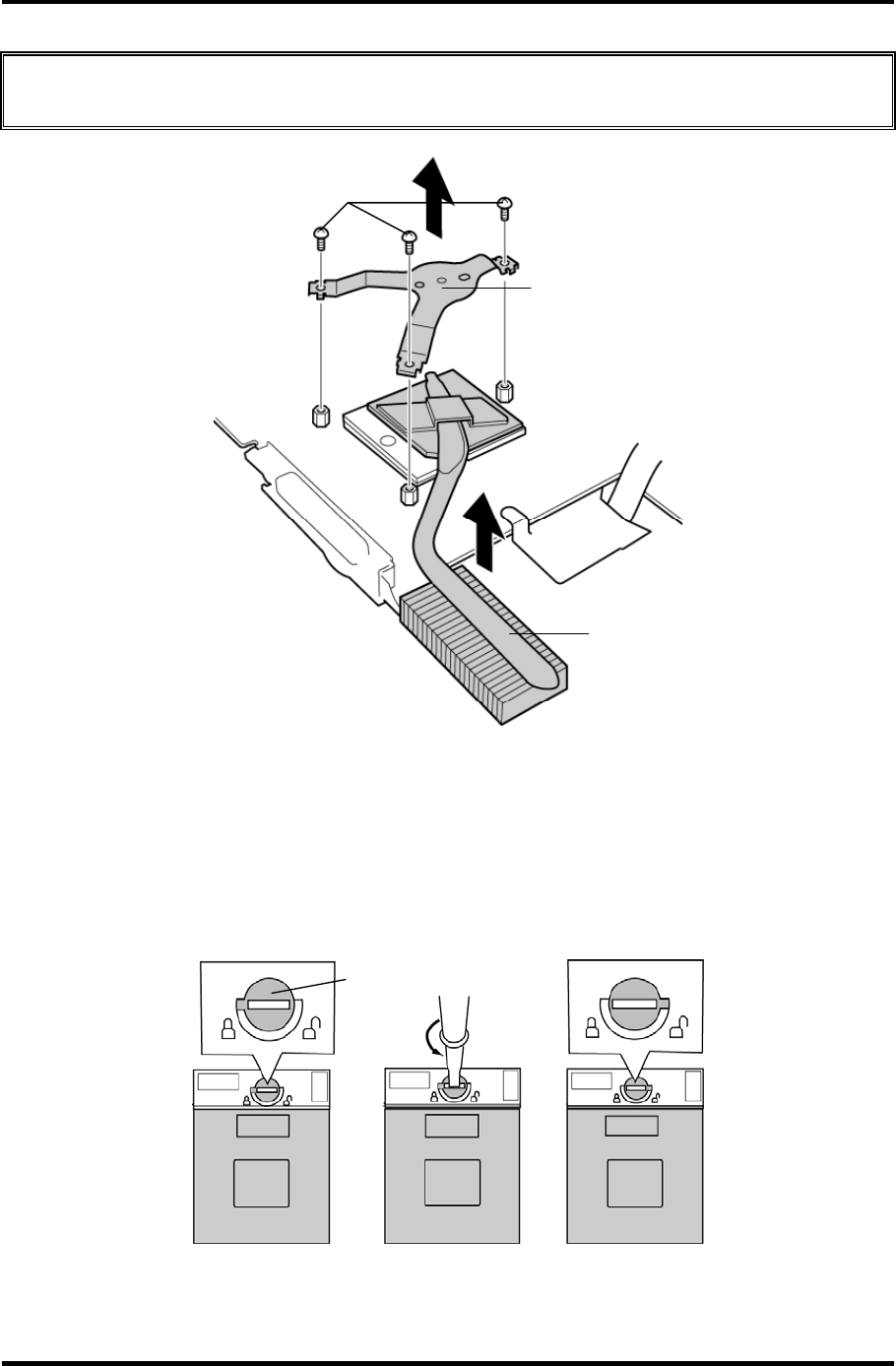
4.19 CPU 4 Replacement Procedures
CAUTION: Silicon grease is applied between the fin and the CPU. When removing the
fin, be careful not to damage the CPU under the fin.
CPU holder
FIN
M2×4B BIND
Figure4-28 Removing the CPU holder and fin
4. Unlock the CPU by rotating the cam on the CPU socket 180 degrees
counterclockwise with a flat-blade screwdriver (in the order shown in the figure
below).
5. Remove the CPU.
Cam
Figure 4-29 Unlocking the CPU
Satellite M30-35 Maintenance Manual (960-455) 4-51
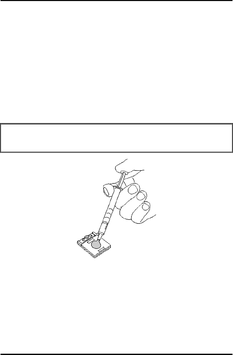
4 Replacement Procedures 4.19 CPU
Installing the CPU
To install the CPU, follow the steps below and refer to figures 4-28 to 4-30.
1. Make sure the cam is in the open position.
2. Seat the CPU in the CPU socket. Make sure the position is exact to avoid damaging
pins on the CPU.
3. Fix the CPU by rotating the cam 180 degrees clockwise with a flat-blade
screwdriver.
4. Apply new grease on the CPU using a special syringe as shown in the following
figure. Apply quarter of scale (0.25ml) of grease evenly on the CPU chip. When
silicon grease is already applied to the CPU, wipe them off with a close in advance.
CAUTION: When installing the CPU, apply new grease on the top of the CPU chip.
When installing the fin, make sure the bottom of the fin covers the top of the
CPU.
Figure 4-30 Applying new grease
5. Install the fin.
6. Place the CPU holder and secure it with the following screws in the order of the
number marked on the holder.
• M2×4B BIND screw ×3
4-52 Satellite M30-35 Maintenance Manual (960-455)
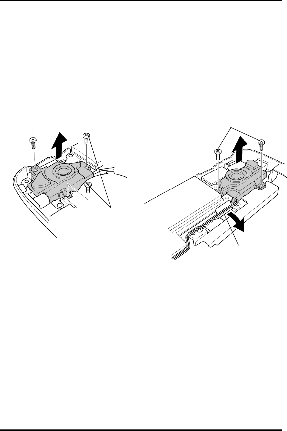
4.20 Speaker 4 Replacement Procedures
4.20 Speaker
Removing the Speaker
To remove the speaker, follow the steps below and refer to figures 4-31 and 4-32.
1. Remove the following screws and peel the insulator.
• M2.5×6B FLAT HEAD screw ×4
• M2.5×4B FLAT HEAD screw ×1 (upper left side)
M2.5×4B FLAT HEAD
M2.5×6B FLAT HEAD
M2.5×6B FLAT HEAD
Insulator
Figure 4-31 Removing the speakers
Satellite M30-35 Maintenance Manual (960-455) 4-53
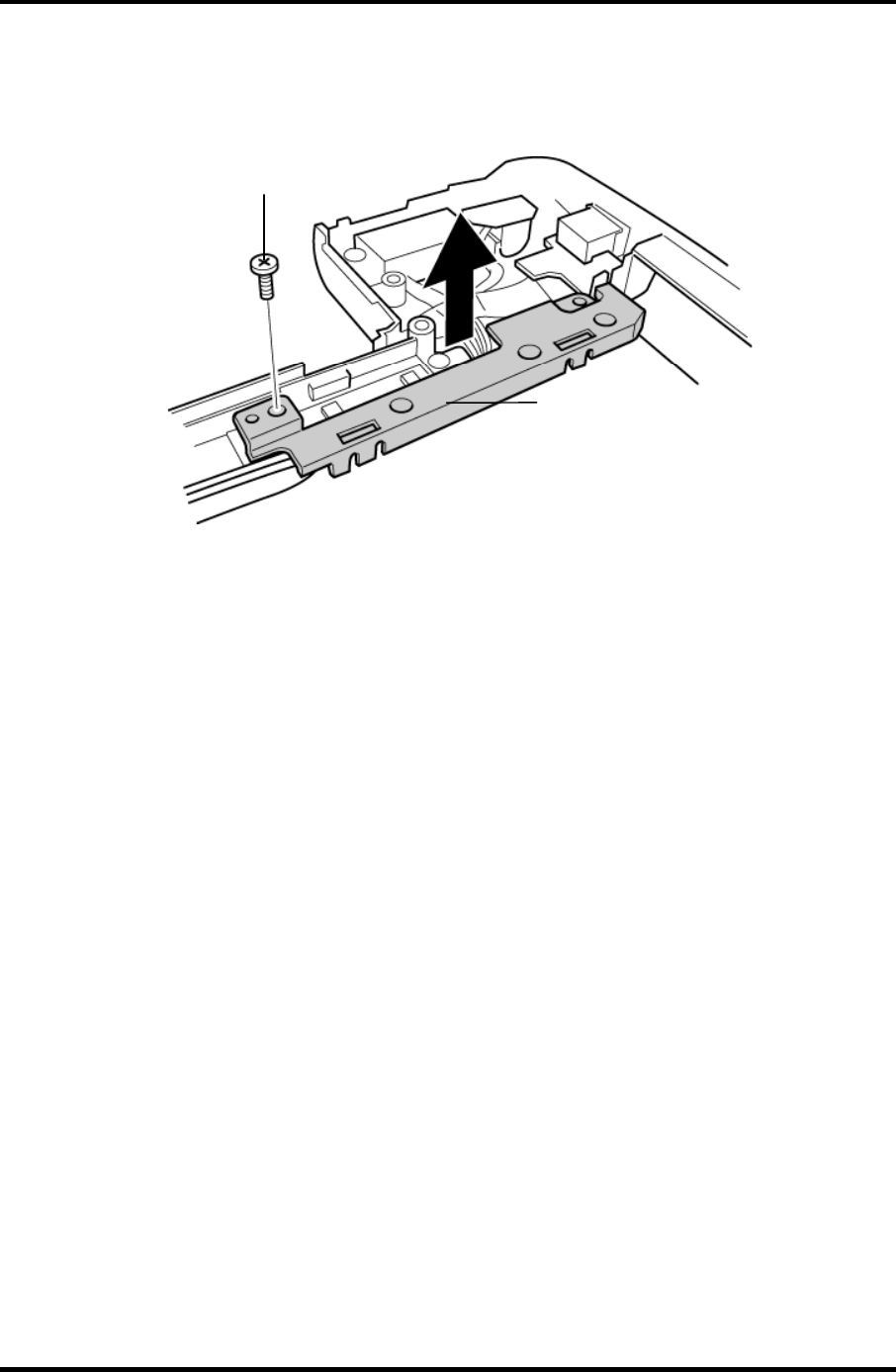
4 Replacement Procedures 4.20 Speaker
2. Remove the following screw and cable holder.
• M2.5×4B FLAT HEAD screw ×1
M2.5×4B FLAT HEAD
Cable holder
Figure 4-32 Removing the cable holder
3. Remove both the speakers.
Installing the Speaker
To install the speaker, follow the steps below and refer to figures 4-31 to 4-32.
1. Set both the speakers.
2. Install the cable holder and secure it with the following screw.
• M2.5×4B FLAT HEAD screw ×1
3. Secure the following screws and stick the insulator to fix the speakers.
• M2.5×6B FLAT HEAD screw ×4
• M2.5×4B FLAT HEAD screw ×1 (upper left side)
4-54 Satellite M30-35 Maintenance Manual (960-455)
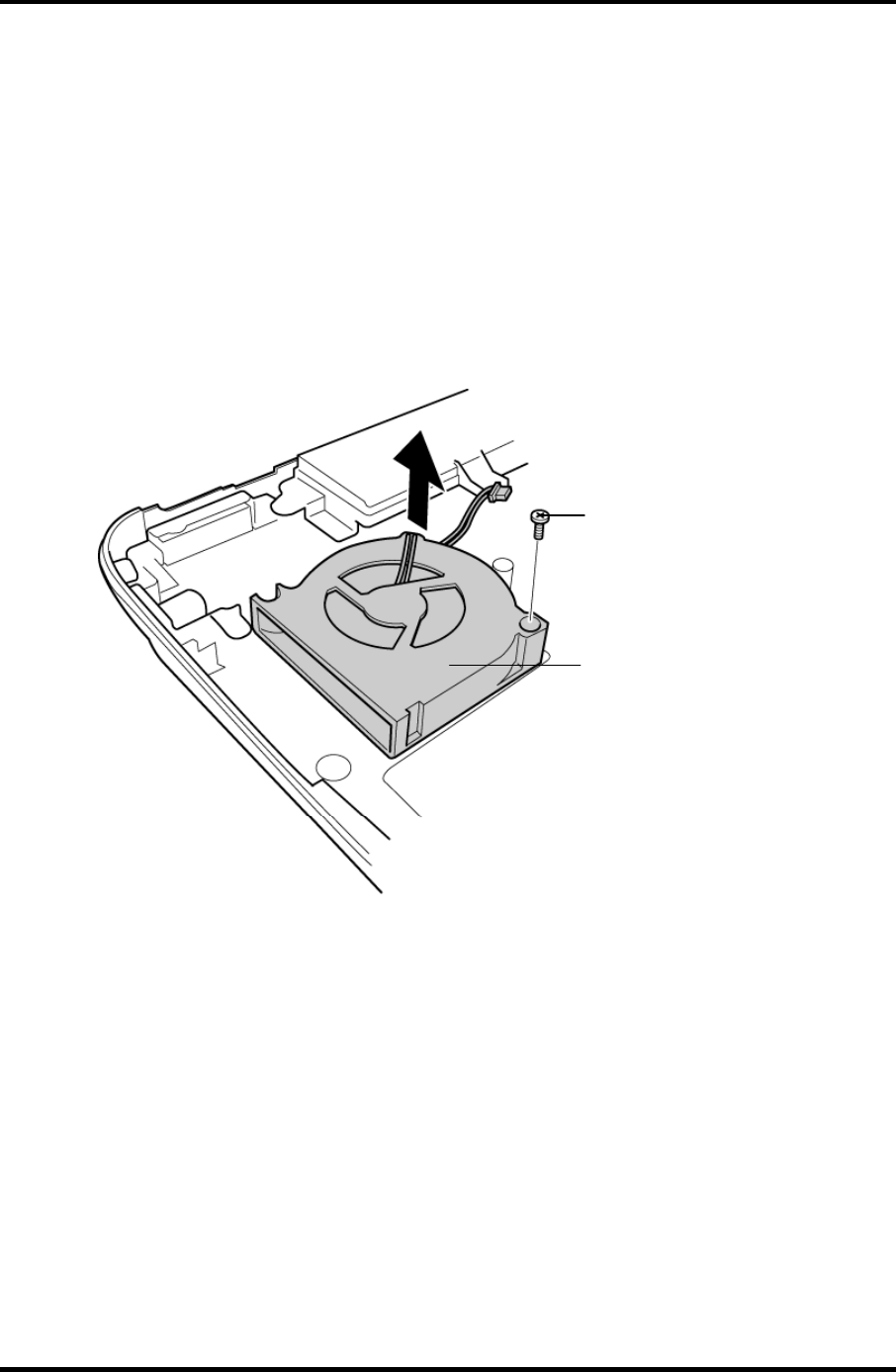
4.21 Fan 4 Replacement Procedures
4.21 Fan
Removing the Fan
To remove the fan, follow the steps below and refer to figure 4-33.
1. Remove the following screws securing the fan.
• M2.5×6B FLAT HEAD screw ×1 (lower right side)
2. Remove the fan.
M2.5
×
6B FLAT HEAD
Fan
Figure4-33 Removing the fan
Installing the Fan
To install the fan, follow the steps below and refer to figure 4-33.
1. Place the fan.
2. Secure the fan with the following screw.
• M2.5×6B FLAT HEAD screw ×1
Satellite M30-35 Maintenance Manual (960-455) 4-55
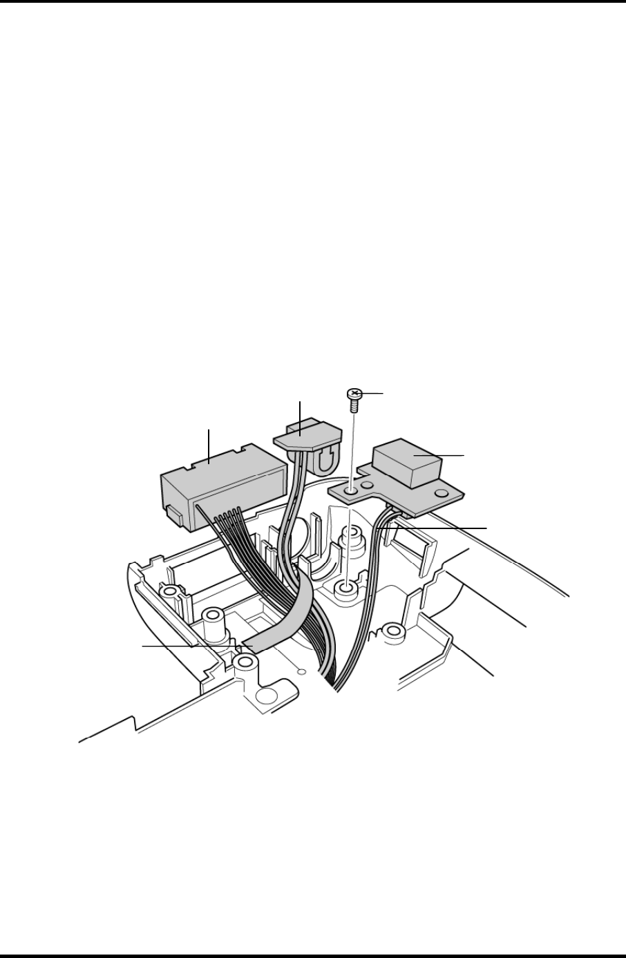
4 Replacement Procedures 4.22 USB Board/DC-IN jack/Network jack
4.22 USB Board/DC-IN jack/Network jack
Removing the USB Board/DC-IN jack/Network jack
To remove the USB board/DC-IN jack/network jack, follow the steps below and refer to
figure 4-34.
1. Remove the following screw securing the USB board.
• M2.5×4B FLAT HEAD screw ×1
2. Disconnect the USB cable from the connector CN1 on the USB board.
3. Peel off the acetate tape and remove the network jack from the slot.
4. Disconnect the DC-IN jack cable from the connector CN1 on the power board and
remove the DC-IN jack.
M2.5
×
4B FLAT HEAD
USB board
DC-IN jack
Network jack
USB cable
A
cetate tape
Figure 4-34 Removing the USB board/DC-IN jack/network jack
4-56 Satellite M30-35 Maintenance Manual (960-455)

4.22 USB Board/DC-IN jack/Network jack 4 Replacement Procedures
Installing the USB Board/DC-IN jack/Network jack
To install the USB board/DC-IN jack/network jack, follow the steps below and refer to the
figure 4-34.
1. Connect the DC-IN jack cable to the connector CN1 on the power board and Install
the DC-IN jack.
2. Install the network jack to the slot and stick the acetate tape.
3. Connect the USB cable to the connector CN1 on the USB board.
4. Place the USB board into the slot and secure it with the following screw.
• M2.5×4B FLAT HEAD screw ×1
Satellite M30-35 Maintenance Manual (960-455) 4-57
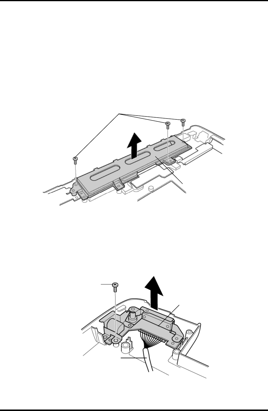
4 Replacement Procedures 4.23 RGB board/Power board
4.23 RGB board/Power board
Removing the RGB board/Power board
To remove the RGB board/Power board, follow the steps below and refer to figures 4-35 to
4-37.
1. Remove the following screws and battery plate.
• M2.5×6 Tapping screw ×3
M2.5
×
6 Tapping
Battery plate
Figure 4-35 Removing the battery plate
2. Remove the following screw and RGB board.
• M2.5×6 Tapping screw ×1
3. Disconnect the RGB cable from the connector CN3 on the RGB board.
M2.5×6 Tapping
RGB board
RGB cable
Figure 4-36 Removing the RGB board
4-58 Satellite M30-35 Maintenance Manual (960-455)
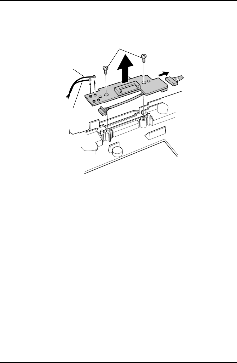
4.23 RGB board/Power board 4 Replacement Procedures
4. Remove the following screws and power board.
• M2.5×6 Tapping screw ×2
M2.5
×
6 Tapping
Battery cable
Wireless LAN cable (white)
Wireless LAN cable (black)
Figure 4-37 Removing the power board
5. Disconnect the wireless LAN cables from the connectors CN6 (white) and CN8
(black) on the power board.
6. Disconnect the battery cable from the connector CN4 on the power board.
Satellite M30-35 Maintenance Manual (960-455) 4-59

4 Replacement Procedures 4.23 RGB board/Power board
Installing the RGB board/Power board
To install the RGB board/Power board, follow the steps below and refer to figures 4-35 to 4-
37.
1. Connect the battery cable to the connector CN4 on the power board.
2. Connect the wireless LAN cables to the connectors CN6 (white) and CN8 (black) on
the power board.
3. Place the power board and secure it with the following screws.
• M2.5×6 Tapping screw ×2
4. Connect the RGB cable to the connector CN3 on the RGB board.
5. Place the RGB board and secure it with the following screws.
• M2.5×6 Tapping screw ×1
6. Place the battery plate and secure it with the following screws.
• M2.5×6 Tapping screw ×3
4-60 Satellite M30-35 Maintenance Manual (960-455)
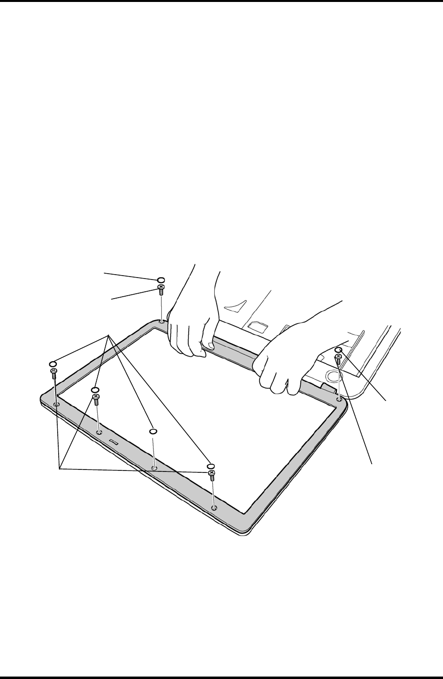
4.24 Display Mask 4 Replacement Procedures
4.24 Display Mask
Removing the Display Mask
To remove the display mask, follow the steps below and refer to figures 4-38.
1. Remove the two mask seals at the lower part of the display mask.
2. Remove the four rubber masks at the top of the display mask.
3. Remove the following screws securing the display mask.
• M2.5×6B FLAT HEAD screw ×2
• M2×4B S-FLAT HEAD screw ×3
4. Release the latches on the display mask and remove the display mask.
M2.5×6B FLAT HEAD
Mask seals
M2×4B S-FLAT HEAD
Rubber masks
Mask seals
M2.5×6B FLAT HEAD
Figure 4-38 Removing the display mask
Satellite M30-35 Maintenance Manual (960-455) 4-61

4 Replacement Procedures 4.24 Display Mask
Installing the Display Mask
To install the display mask, follow the steps below and refer to figures 4-38.
1. Place the display mask on the LCD module.
2. Engage the latches of the display mask.
3. Secure the display mask with the following screws.
• M2.5×6B FLAT HEAD screw ×2
• M2×4B S-FLAT HEAD screw ×3
4. Stick the four rubber masks at the top of the display mask.
5. Stick the two mask seals at the lower part of the display mask.
4-62 Satellite M30-35 Maintenance Manual (960-455)
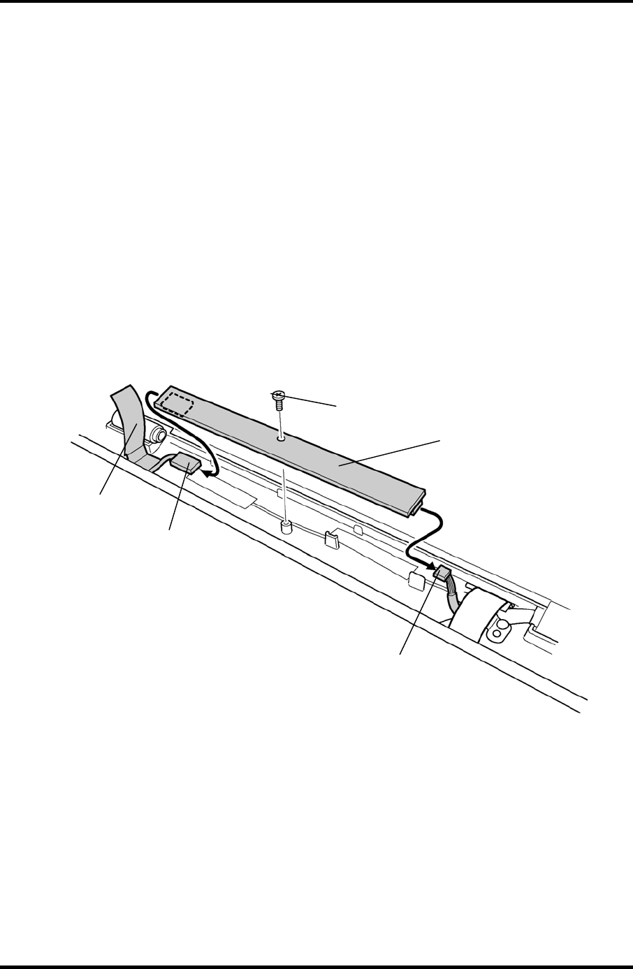
4.25 FL Inverter 4 Replacement Procedures
4.25 FL Inverter
Removing the FL Inverter
To remove the FL inverter, follow the steps below and refer to figure 4-39.
1. Remove the following screw securing the FL inverter.
• M2×4B S-FLAT HEAD screw ×1
2. Peel the insulator on the FL inverter.
3. Disconnect the FL cable under the insulator from the FL inverter.
4. Disconnect the HV cable from the FL inverter.
5. Remove the FL inverter.
M2
×
4B S-FLAT HEAD
Insulator
FL inverter
FL cable
HV cable
Figure 4-39 Removing the FL inverter
Satellite M30-35 Maintenance Manual (960-455) 4-63

4 Replacement Procedures 4.25 FL Inverter
Installing the FL Inverter
To install the FL inverter, follow the steps below and refer to figure 4-39.
1. Connect the FL cable and the HV cable to the FL inverter.
2. Seat the FL inverter and stick the insulator on the FL inverter of the FL cable side.
3. Secure the FL inverter with the following screw.
• M2×4B S-FLAT HEAD screw ×1
4-64 Satellite M30-35 Maintenance Manual (960-455)

4.26 LCD Module 4 Replacement Procedures
4.26 LCD Module
NOTE: 1) Be careful not to apply pressure to the ICs along the edge of LCD module.
The ICs are easily damaged.
2) For environmental reasons, do not throw away a malfunctioning LCD module
(or FL). Please follow local ordinances or regulations for its disposal.
Removing the LCD Module
To remove the LCD Module, follow the steps below and refer to figures 4-40 and 4-41.
1. Remove the four mask seals on the sides of the LCD module.
2. Remove the following screws securing the LCD module.
• M2×4B S-FLAT HEAD screw ×4
3. With the bottom edge of the LCD unit on the display cover, lift the top edge of the
LCD unit.
4. Remove the copper tape securing the LCD cable.
Satellite M30-35 Maintenance Manual (960-455) 4-65
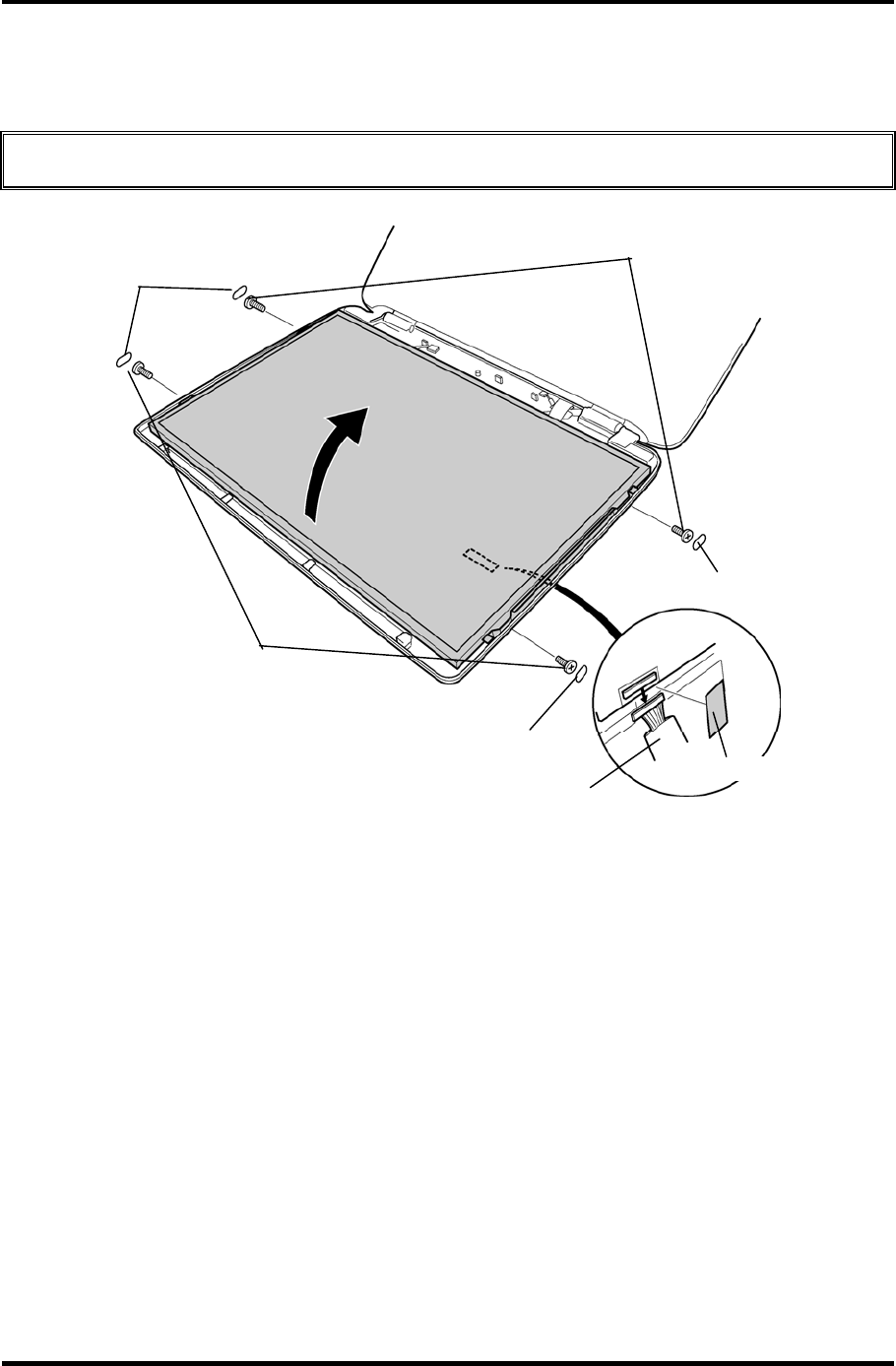
4 Replacement Procedures 4.26 LCD Module
5. Disconnect the LCD cable from the connector on the back of the LCD and remove
the LCD module.
CAUTION: When removing the LCD cable, be careful not to damage the connector.
M2×4B S-FLAT HEAD
Mask seal
Mask seal
Mask seal
LCD cable Copper tap
e
M2
×
4B S-FLAT HEAD
Figure 4-40 Removing the LCD module (1)
4-66 Satellite M30-35 Maintenance Manual (960-455)
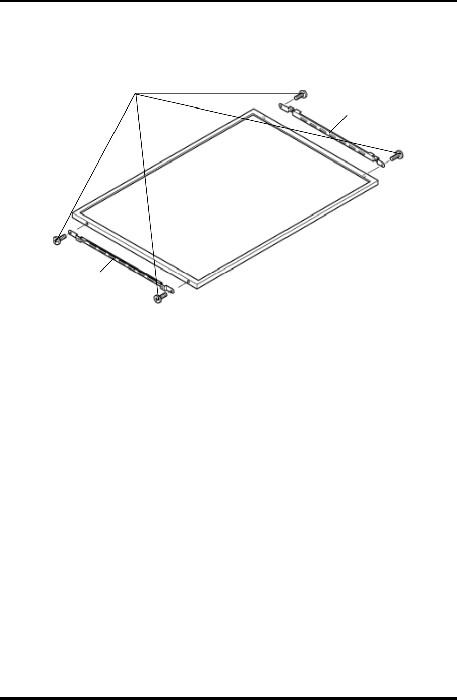
4.26 LCD Module 4 Replacement Procedures
6. Remove the following screws securing the two metal braces to the LCD module.
• M2×3C S-FLAT HEAD screw ×4
Metal brace
Metal brace
M2×3C S-FLAT HEAD
Figure 4-41 Removing the LCD module (2)
Satellite M30-35 Maintenance Manual (960-455) 4-67

4 Replacement Procedures 4.26 LCD Module
Installing the LCD Module
To install the LCD module, follow the steps below and refer to figures 4-40 and 4-41.
1. Secure the two metal braces to the LCD module with the following screws.
• M2×3C S-FLAT HEAD screw ×4
2. Set the LCD module on the display cover.
3. Connect the LCD cable to the connector on the back of the LCD module. Stick the
copper tape on the LCD cable.
4. Seat the LCD module and secure it with the following screws.
• M2×4B S-FLAT HEAD screw ×4
5. Stick the four mask seals on the sides of the LCD module.
4-68 Satellite M30-35 Maintenance Manual (960-455)
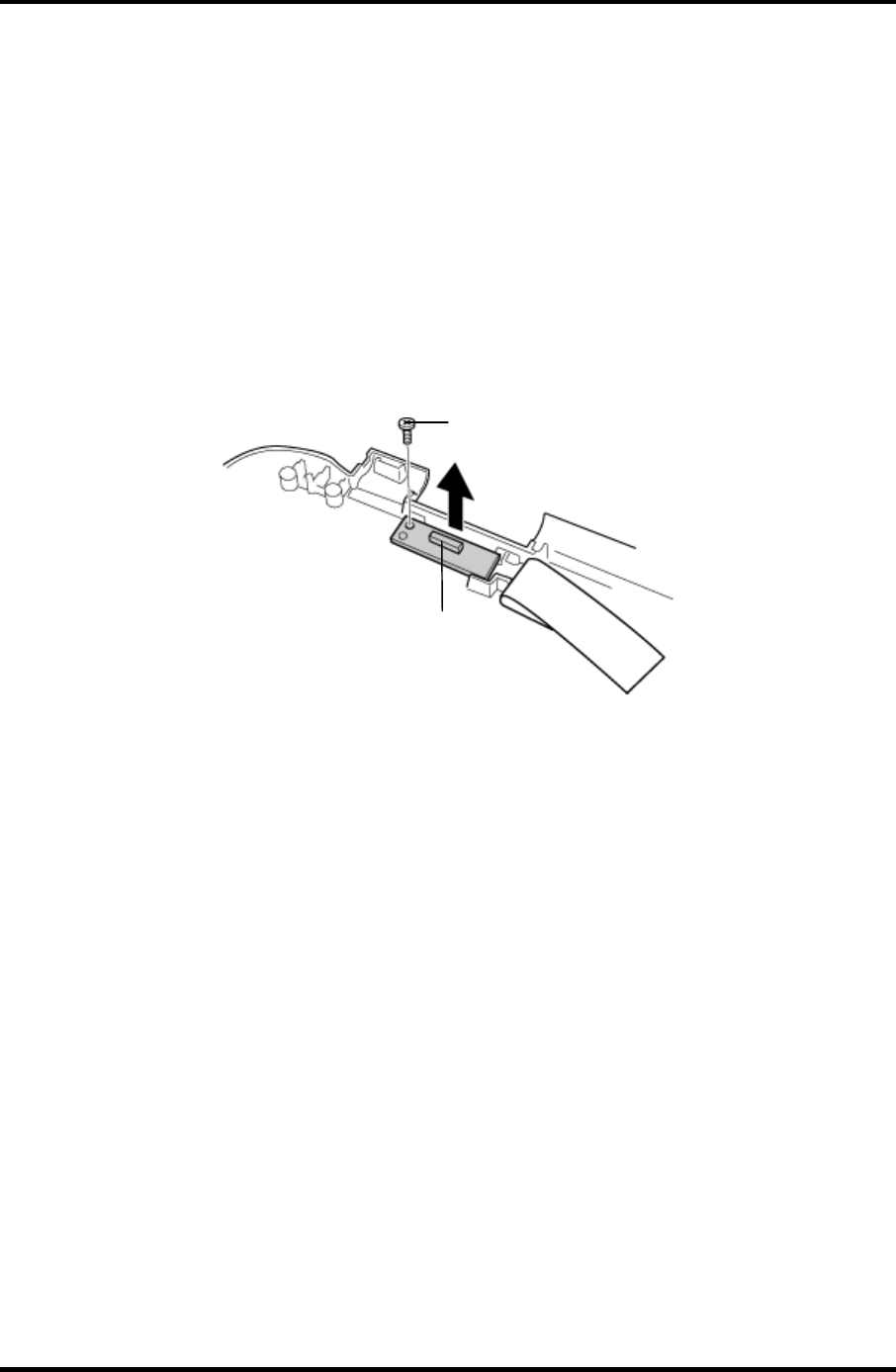
4.27 Sensor/Switch Board 4 Replacement Procedures
4.27 Sensor/Switch Board
Removing the Sensor/Switch Board
To remove the sensor/switch board, make sure the computer is in boot mode and powered
off, follow the steps below and refer to figure 4-42.
1. Remove the following screws securing the sensor/switch board.
• M2×4B S-FLAT HEAD screw ×1
2. Remove the sensor/switch board.
M2
×
4B S-FLAT HEAD
Sensor/Switch board
Figure 4-42 Removing the sensor/switch board
3. Pull out the sensor/switch board cable.
Installing the Sensor/Switch Board
To install the sensor/switch board, make sure that the computer is in boot mode and powered
off, follow the steps below and refer to figure 4-42.
1. Place the sensor/switch board in the slot and secure it with the following screw.
• M2×4B S-FLAT HEAD screw ×1
2. Pass the sensor/switch board cable through the hole under the hinge cover.
3. Arrange the sensor/switch board cable along with the guides.
Satellite M30-35 Maintenance Manual (960-455) 4-69
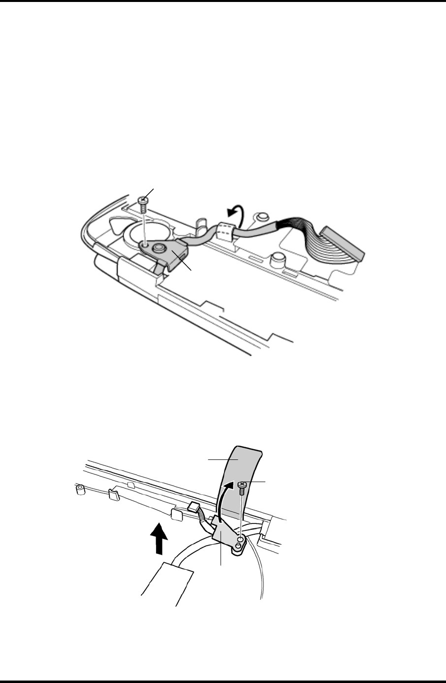
4 Replacement Procedures 4.28 LCD cable/Wireless LAN Antenna/Hinge
4.28 LCD cable/Wireless LAN Antenna/Hinge
Removing the LCD cable/Wireless LAN Antenna
To remove the LCD cable/wireless LAN antenna, follow the steps below and refer to figures
4-43 to 4-49.
1. Remove the following screw and LCD cable holder on the back.
• M2.5×5B FLAT HEAD screw ×1
M2.5
×
5B FLAT HEAD
LCD cable holder
Figure 4-43 Removing the LCD cable holder
2. Peel the insulator and remove the following screw and cable holder on the front.
• M2.5×4B FLAT HEAD screw ×1
M2.5
×
4B FLAT HEAD
Cable holder
Insulator
Figure 4-44 Removing the cable holder
4-70 Satellite M30-35 Maintenance Manual (960-455)
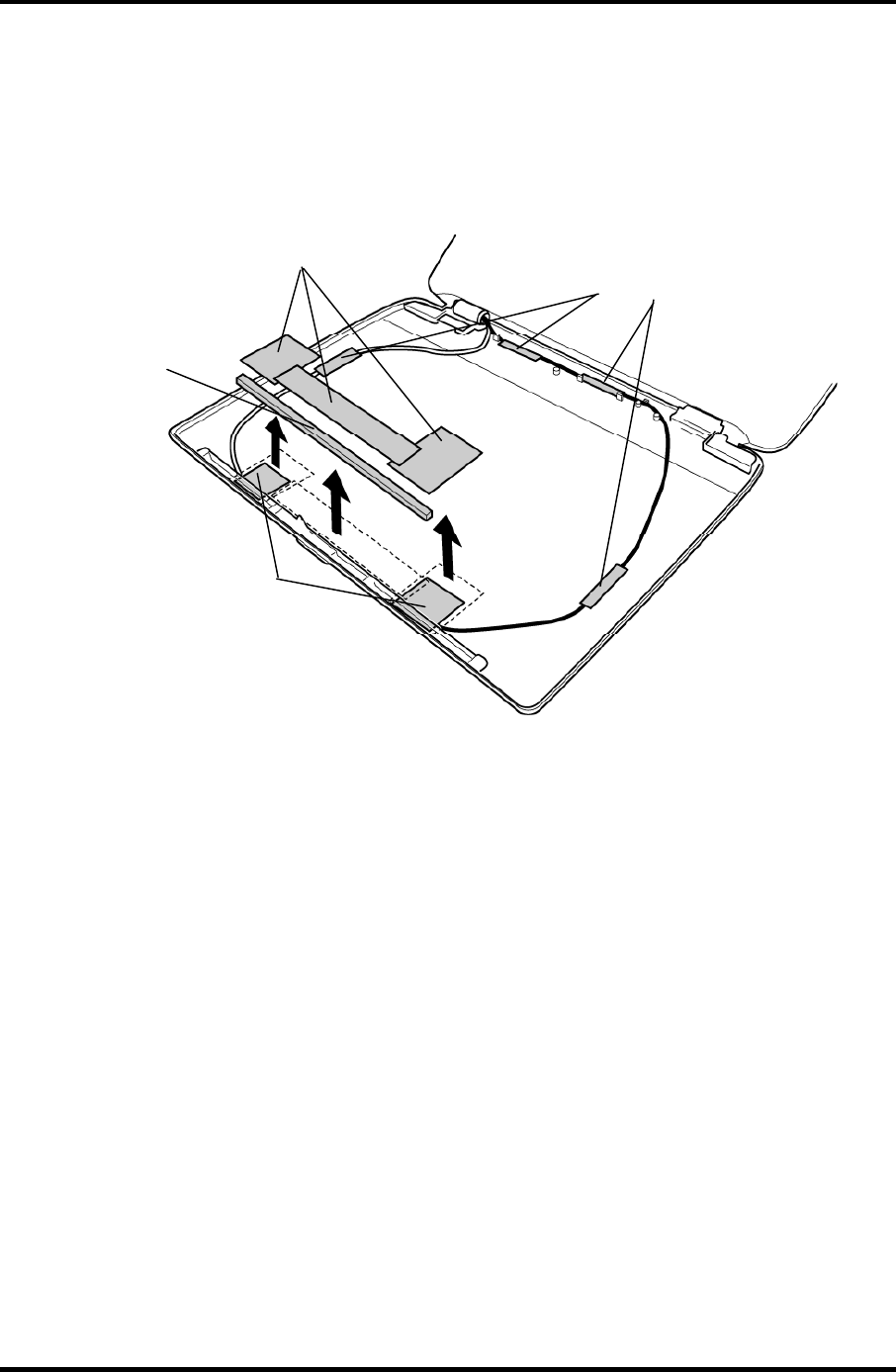
4.28 LCD cable/Wireless LAN Antenna/Hinge 4 Replacement Procedures
3. Peel off the four acetate tapes fixing the wireless LAN antenna cable.
4. Peel off the three copper sheets and the gasket fixing the wireless LAN antenna.
5. Peel off both the wireless LAN antennas and pull out the cables through the hole
under the hinge cap.
A
cetate tape
Copper sheets
Gasket
Wireless LAN antenna
Figure 4-45 Removing the wireless LAN antenna
Satellite M30-35 Maintenance Manual (960-455) 4-71
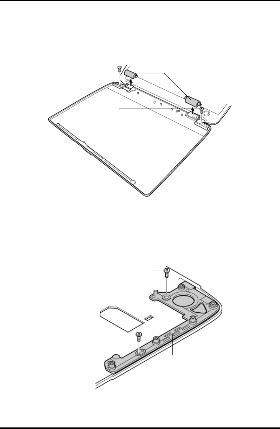
4 Replacement Procedures 4.28 LCD cable/Wireless LAN Antenna/Hinge
6. Remove the hinge caps.
7. Remove the following screws fixing the hinges on the display cover.
• M2.5×4B FLAT HEAD screw ×2
M2.5×4B FLAT HEAD
Hinge cap
Figure 4-46 Removing the hinge cap
8. Remove the following screws and hinge (on the LCD cable side).
• M2×4B S-FLAT HEAD screw ×1
• M2.5×5B FLAT HEAD screw ×1
M2.5×5B FLAT HEAD
M2×4B S-FLAT HEAD
Hinge
Figure 4-47 Removing the hinge (LCD cable side)
4-72 Satellite M30-35 Maintenance Manual (960-455)
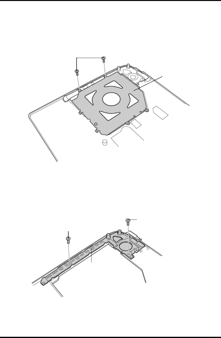
4.28 LCD cable/Wireless LAN Antenna/Hinge 4 Replacement Procedures
9. Pull out the LCD cable.
10. Remove the following screws and circle plate.
• M2×4B S-FLAT HEAD screw ×2
M2×4B S-FLAT HEAD
Circle plate
Figure 4-48 Removing the circle plate
11. Remove the following screws and hinge (on the other side).
• M2×4B S-FLAT HEAD screw ×1
• M2.5×5B FLAT HEAD screw ×1
M2.5
×
5B FLAT HEAD
M2×4B S-FLAT HEAD
Hinge
Figure 4-49 Removing the hinge
Satellite M30-35 Maintenance Manual (960-455) 4-73

4 Replacement Procedures 4.28 LCD cable/Wireless LAN Antenna/Hinge
Installing the LCD cable/Wireless LAN Antenna
To install the wireless LAN antenna/Bluetooth antenna/display cover/speaker, follow the
steps below and refer to figures 4-43 to 4-50.
1. Pass the LCD cable through the slot and guide.
2. Set the hinge (on the opposite side of the LCD cable) and secure it with the following
screws.
• M2×4B S-FLAT HEAD screw ×1
• M2.5×5B FLAT HEAD screw ×1
3. Place the circle plate and secure it with the following screws.
• M2×4B S-FLAT HEAD screw ×2
4. Set the hinge (LCD cable side) and secure it with the following screws.
• M2×4B S-FLAT HEAD screw ×1
• M2.5×5B FLAT HEAD screw ×1
5. Secure the hinges on the display cover with the following screws.
• M2.5×4B FLAT HEAD screw ×2
6. Install the hinge cap (on the LCD cable side).
7. Pass the wireless LAN antenna cables through the hole to the back.
8. Arrange the wireless LAN antenna cables along the guides on the back and fix them
with two acetate tapes.
9. Secure the wireless LAN antenna cables with the four acetate tapes.
4-74 Satellite M30-35 Maintenance Manual (960-455)
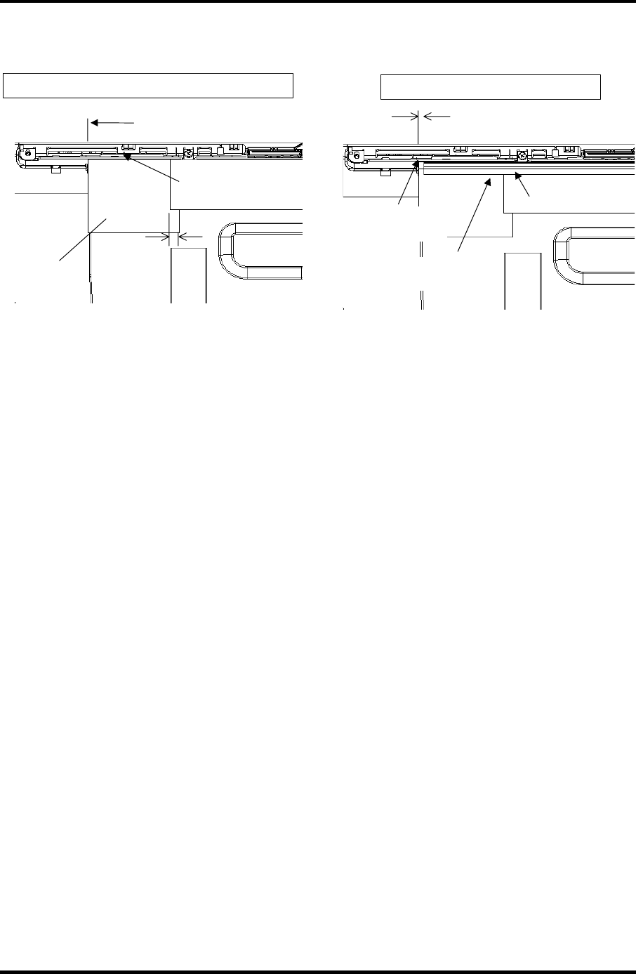
4.28 LCD cable/Wireless LAN Antenna/Hinge 4 Replacement Procedures
Satellite M30-35 Maintenance Manual (960-455) 4-75
10. Secure the wireless LAN antenna with the three copper sheets and the gasket.
Standard for sticking position of copper sheets (right , left)
The copper sheet shall not
be over the edge of the wall
of LCD cover.
5 ± 4 mm
Copper sheet
Fit the copper sheet to the
hole edge of the LCD cover.
Standard for sticking position of gasket
gasket
Sticking side of gasket
(wall of LCD cover)
2.5 ± 2 mm
Stick the gasket securely so
that it fits the copper tape.
Figure 4-50 Sticking the copper sheets and gasket
11. Set the LCD cable holder on the back and secure it with the following screw.
• M2.5×5B FLAT HEAD screw ×1
12. Set the Cable holder on the front and secure it with the following screw and the
insulator.
• M2.5×4B FLAT HEAD screw ×1
12. Place the hinge caps.
4 Replacement Procedure 4.29 Fluorescent Lamp
4
4.29 Fluorescent Lamp
This system uses LCD modules from the following suppliers. The procedure for replacing
the fluorescent lamp is different for each LCD module. Refer to the appropriate procedure.
Type Part No. Supplier Section Page
G33C0001H110 TMD 4.29.1 4-76
G33C0001F110 LG.Philips 4.29.2 4-88
15.4-inch WXGA
G33C0001D110 Samsung 4.29.3 4-95
G33C0001G110 LG.Philips 4.29.2 4-88
15.4-inch WXGA
(CSV)
G33C0001E110 Samsung 4.29.3 4-95
NOTE: - When working with a LCD module, always use a flat, grounded table.
- Handle the backlight unit in the environment without dust, such as on the clean
bench. Keep the worktable free from any screws or other material that may
scratch the LCD surface.
- Use an anti-static or protective sheet.
- When replacing the FL unit, cover with a finger protector or similar to prevent
soiling or scratching the LCD panel.
- Be careful when handling the lamp. Excessive force may break the lamp.
- Be careful not to soil or deform the lamp reflector.
- Make sure that the power of the LCD module is turned off before connecting or
disconnecting cables and connectors.
4-76 Satellite M30-35 Maintenance Manual (960-455)

4.29 Fluorescent Lamp 4 Replacement Procedure
4.29.1 Replacing the 15.4-inch WXGA TMD Fluorescent Lamp
CAUTION: When replacing the fluorescent lamp, wear finger covers or gloves to avoid
contaminating or damaging the LCD panel. Be careful not to let dust or other foreign
substance into the module.
Disassembling the 15.4-inch WXGA TMD Fluorescent Lamp
To disassemble the 15.4-inch WXGA TMD fluorescent lamp, follow the steps below and
refer to figures 4-51 to 4-55.
1. Removing tapes and insulation sheets from LCD module
1) Place the LCD module face down on a flat table that has no alien substance on
it. Make sure there is no dust on the desk to avoid scratching the surface of the
LCD module. Place a protective sheet (such as soft cloth) on the surface.
2) Remove the fixing tape for the FL cable, two tapes at the side of lamp, X-PCB
insulation sheet and Y-PCB insulation sheet from the LCD module in order as
shown in the figure below.
Satellite M30-35 Maintenance Manual (960-455) 4-77
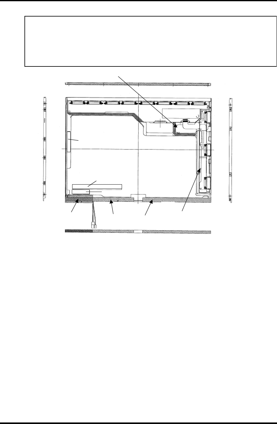
4 Replacement Procedure 4.29 Fluorescent Lamp
NOTE: 1) Be careful not to give any damage to the TAB.
2) The X-PCB insulation sheet should be left attached to the bezel, as it
will be recycled.
3) The Y-PCB insulation sheet shall not be disposed after removed, as it
will be recycled.
Fixing tape for
FL cable (2) Bezel tape (4) Y-PCB insulation sheet
Product Label
(3) X-PCB insulation sheet
Caution Label
Backlight Serial Number Label
Destruction Label
Figure 4-51 Replacing TMD fluorescent lamp (WXGA) (1)
4-78 Satellite M30-35 Maintenance Manual (960-455)
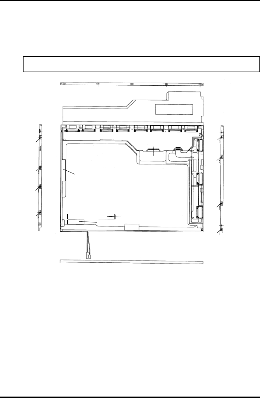
4.29 Fluorescent Lamp 4 Replacement Procedure
2. Removing screws
1) Spread out the insulation sheet without detaching from the side of bezel.
2) Remove the screws (left side, right side) in order as shown in the figure below.
NOTE: Use a Philips screwdriver with type 0 bit to remove the screws.
Product Label
Destruction Label
Caution Label
Backlight Serial Number Label
(2)
(2)
(2)
(2)
(1)
(1)
(1)
(1)
Figure 4-52 Replacing TMD fluorescent lamp (WXGA) (2)
Satellite M30-35 Maintenance Manual (960-455) 4-79
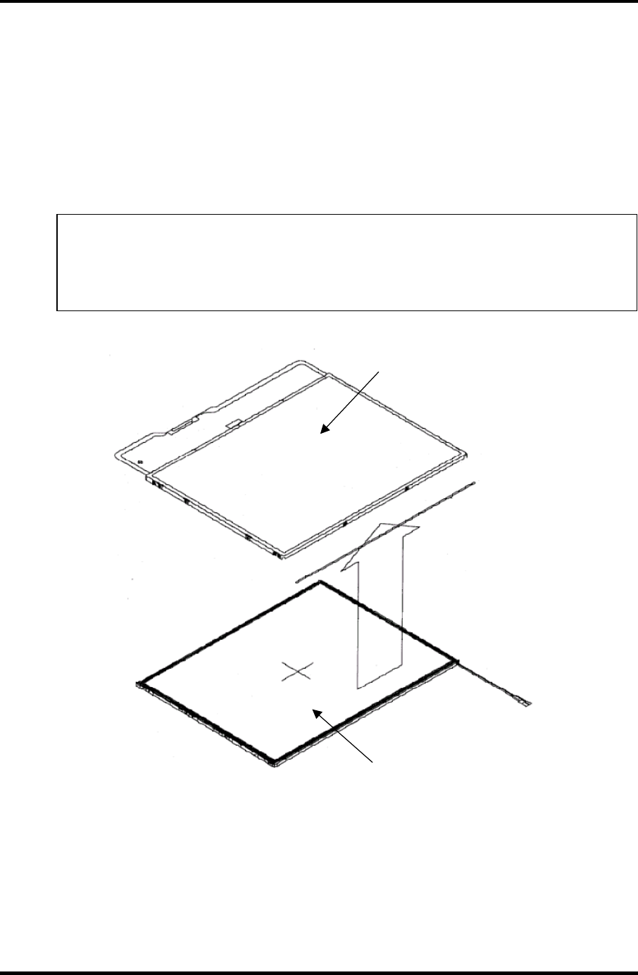
4 Replacement Procedure 4.29 Fluorescent Lamp
3. Removing bezel
1) Turn the LCD module face up with the insulation sheets on it.
2) Release the latches of the bezel and frame. (five points on upper side, two
points lower side)
3) Remove the double-sided adhesive tape on the bottom of the side of bezel, and
remove the bezel.
NOTE: 1) Be careful not to damage the TAB when releasing the upper latches.
2) When removing the bezel, be sure to remove the double-sided
adhesive tapes on the lower side of bezel slowly so as not to break
the cell. Be careful not to deform the bezel.
Bezel
Backlight unit
Figure 4-53 Replacing TMD fluorescent lamp (WXGA) (3)
4-80 Satellite M30-35 Maintenance Manual (960-455)
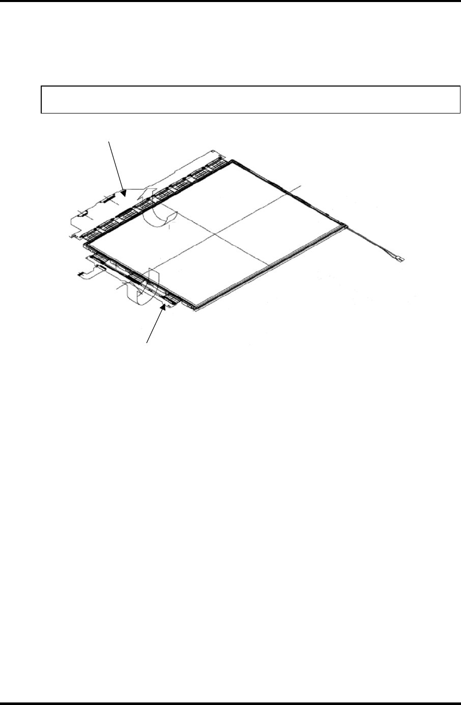
4.29 Fluorescent Lamp 4 Replacement Procedure
4. Spreading out PCB
1) Spread out the X-PCB and Y-PCB horizontally in order.
NOTE: Be careful not to damage the TAB.
(1) Spread out the X-
PCB from the back.
(2) Spread out the Y-
PCB from the back.
Figure 4-54 Replacing TMD fluorescent lamp (WXGA) (4)
Satellite M30-35 Maintenance Manual (960-455) 4-81
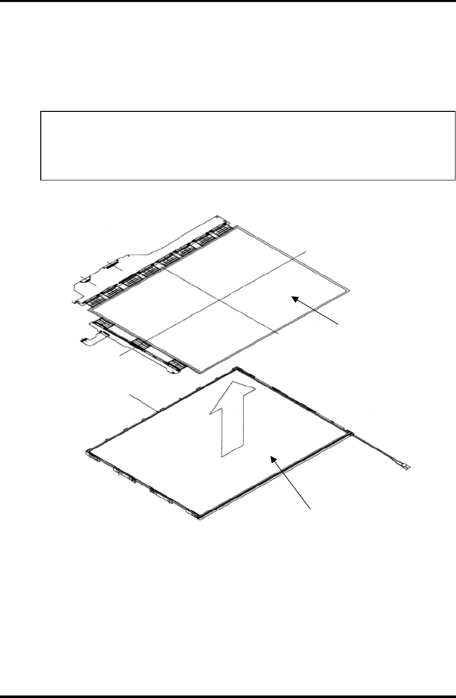
4 Replacement Procedure 4.29 Fluorescent Lamp
5. Removing PCB-ASSY cell
1) Remove the PCB-ASSY cell from the backlight unit.
2) Remove the double-sided adhesive tape from the back of the cell.
NOTE: 1) Remove the tape slowly not to break the cell. The cell and frame are
glued by double-sided adhesive tape.
2) Be careful not to remove the light shielding tapes from the upper left
and right sides of the cell.
PCB-ASSY cell
Backlight unit
Remove the cell by
peeling off the double-
sided adhesive ta
p
e.
Figure 4-55 Replacing TMD fluorescent lamp (WXGA) (5)
4-82 Satellite M30-35 Maintenance Manual (960-455)
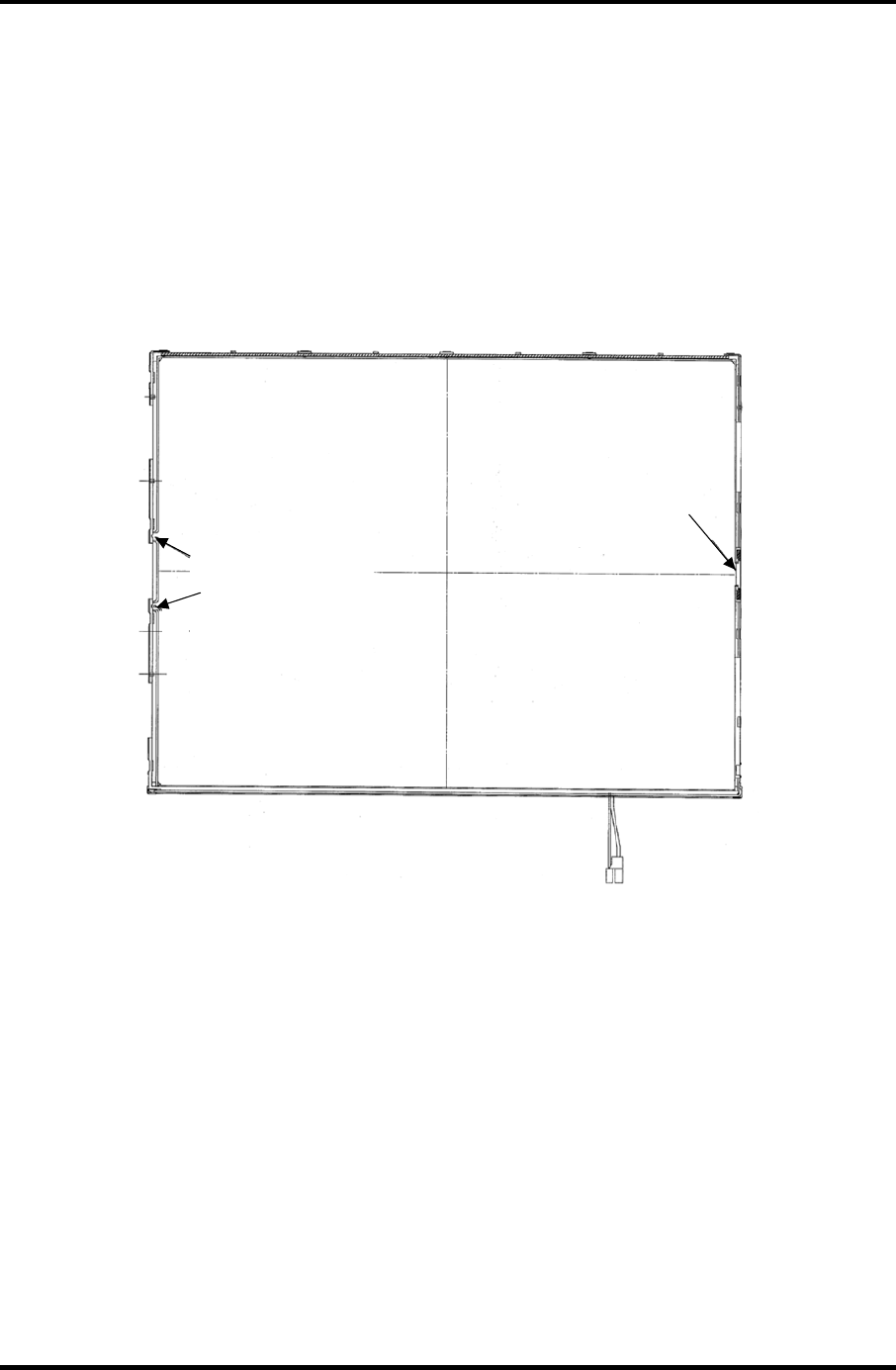
4.29 Fluorescent Lamp 4 Replacement Procedure
Assembling the 15.4-inch WXGA TMD Fluorescent Lamp
To assemble the 15.4-inch WXGA TMD fluorescent lamp, follow the steps below and refer
to figures 4-56 to 4-61.
1. Checking backlight
1) Check the following items shown in the figure below.
Make sure the sheet does
not come off the frame.
Fixing tape for sheet
Figure 4-56 Replacing TMD fluorescent lamp (WXGA) (6)
Satellite M30-35 Maintenance Manual (960-455) 4-83
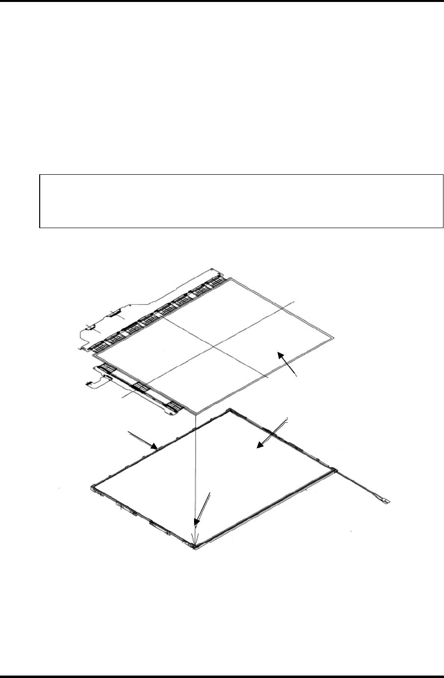
4 Replacement Procedure 4.29 Fluorescent Lamp
2. Assembling PCB-ASSY cell
1) Remove the release paper of the double-sided tape at the upper of the
backlight unit.
2) Light up the backlight.
3) Make sure there is no dust, alien substance or scratch on the backlight. Then
make sure there is nothing wrong with the back of cell, install the PCB-ASSY
cell to the backlight unit.
NOTE: 1) When installing the PCB-ASSY cell, fit it to the left bottom corner of
the backlight unit.
2) Be careful not to damage the TAB.
Cell with PCB
Backlight unit
Fit to the left
bottom corner.
Remove the release
paper of the double-
sided adhesive tape.
Figure 4-57 Replacing TMD fluorescent lamp (WXGA) (7)
4-84 Satellite M30-35 Maintenance Manual (960-455)
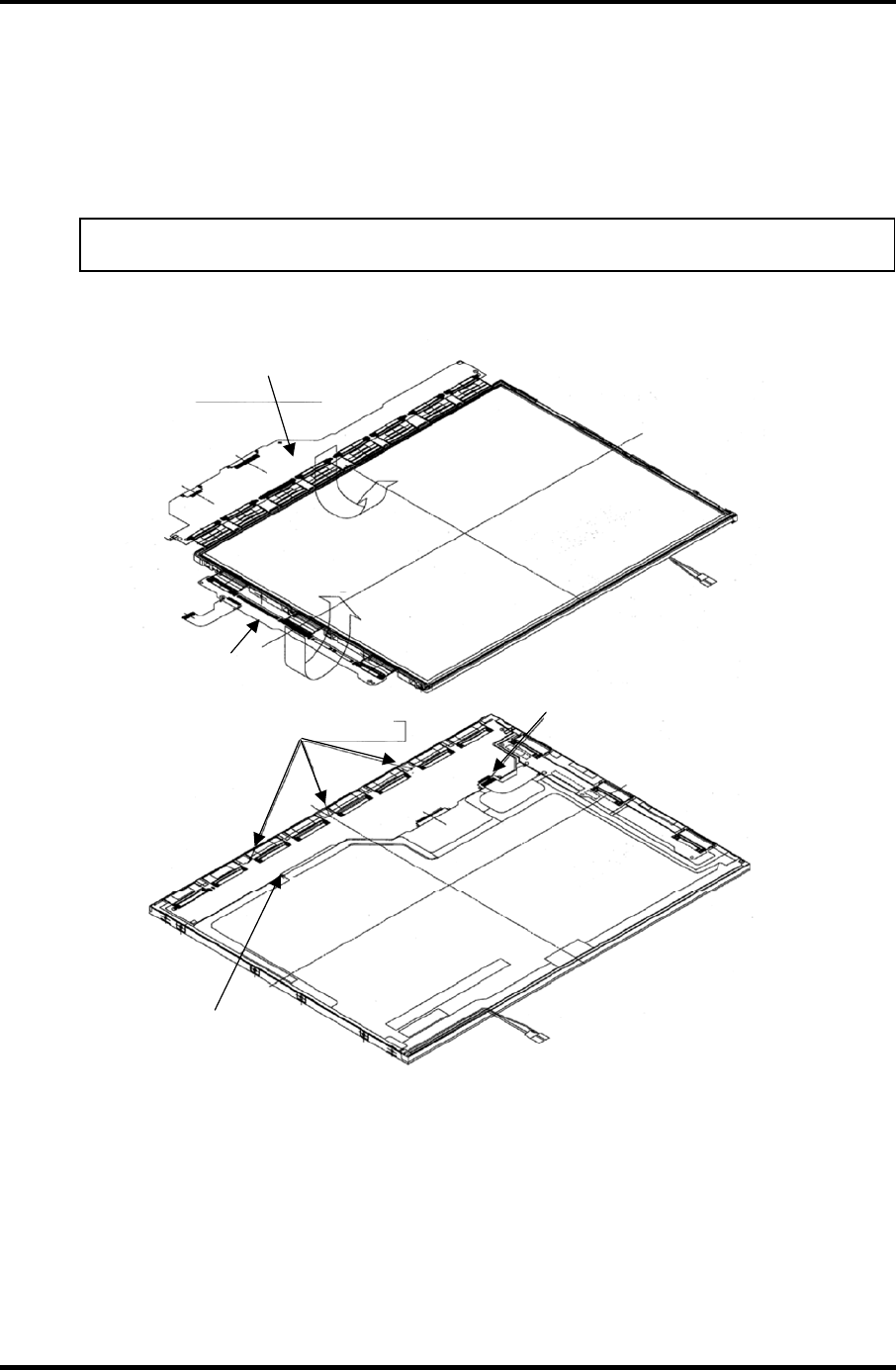
4.29 Fluorescent Lamp 4 Replacement Procedure
3. Folding and temporary fixing of TAB/PCB
1) Fold the X-TAB (X-PCB) and Y-TAB (Y-PCB) to the back of backlight unit.
2) Hook the X-PCB on the three latches on the back of frame.
NOTE: Be careful not to damage the TAB.
(1) Fold the X-PCB to the back.
(2) Fold the Y-PCB
to the back.
Insert the FPC into the connector.
The PCB shall not be
installed over the frame.
The PCB shall be hooked on the
three latches of the frame.
Figure 4-58 Replacing TMD fluorescent lamp (WXGA) (8)
Satellite M30-35 Maintenance Manual (960-455) 4-85
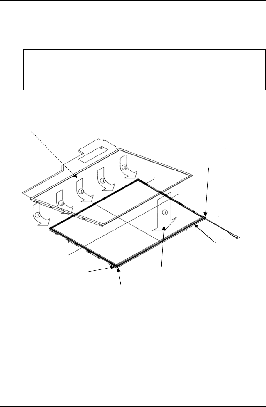
4 Replacement Procedure 4.29 Fluorescent Lamp
4. Setting bezel
1) Hook the bezel on the five latches of the frame from the upper side.
NOTE: 1) Make sure the GND-CU on the left side and lamp reflector shall be
inside the bezel.
2) Be careful not to damage the TAB.
3) Make sure the five latches of the upper side of bezel are hooked on.
The cable shall not be
outside the bezel.
Make sure the gum projection
for protecting the cable is not
outside th ebezel.
(2) Align the bezel with the
lamp side of the backlight unit.
(1) Install the bezel from the
TAB side. Be careful not to
damage the TAB. Hook the
bezel on the five latches.
Make sure the fold of reflector
is not outside the bezel.
Make sure the gum projection
for protecting the cable is not
outside th ebezel.
Figure 4-59 Replacing TMD fluorescent lamp (WXGA) (9)
4-86 Satellite M30-35 Maintenance Manual (960-455)
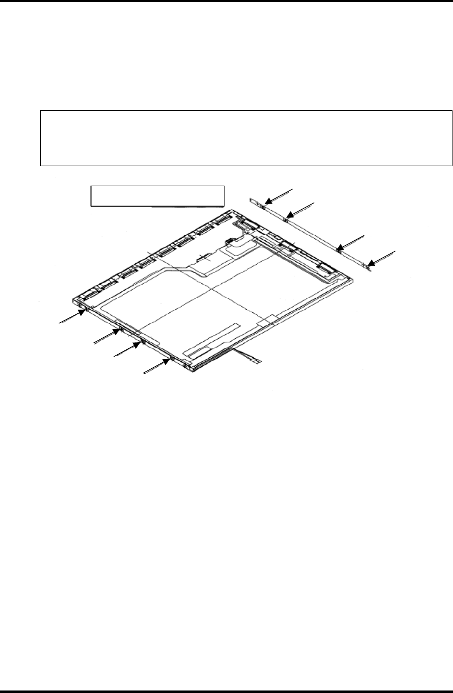
4.29 Fluorescent Lamp 4 Replacement Procedure
5. Fixing PCBs and bezel with screws
1) Tighten the left side with the screws in order shown in the figure below.
2) Tighten the right side with the screws in order shown in the figure below.
NOTE: 1) Tighten the screws in order. Make sure there is no floating of screw.
2) The screw tightening torque shall be 0.147mN
•
m (1.5kgf
•
cm).
3) Use a Philips screwdriver with type 0 bit.
Tighten the eight screws.
(1)
(2)
(3)
(4)
(8)
(7)
(6)
(5)
Figure 4-60 Replacing TMD fluorescent lamp (WXGA) (10)
Satellite M30-35 Maintenance Manual (960-455) 4-87
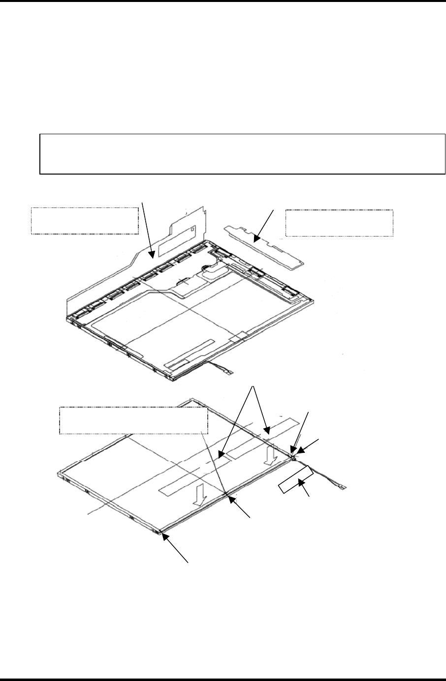
4 Replacement Procedure 4.29 Fluorescent Lamp
6. Sticking tapes and insulation sheets
1) Stick the Y-PCB insulation sheet and X-PCB insulation sheet in order.
2) Stick the two bezel tapes on the lower side (lamp side).
3) Stick the fixing tape for FL cable.
NOTE: Be careful not to damage to the TAB or the pulling-out part of lamp
cable when sticking the tapes and insulation sheets.
Stick the X-PCB
insulation sheet. Stick the Y-PCB
insulation sheet.
Stick the insulation sheet
without any flexure. Stick the insulation sheet
without any flexure.
Stick the bezel tape while pressing
not to cause floating of bezel.
Standard for sticking bezel
tape. Stick the tape between
the mark-off lines.
Standard for sticking bezel
tape. Stick the tape between
the mark-off lines.
Standard for sticking bezel
tape. Stick the tape between
the mark-off lines.
Standard for fixing
tape for FL cable.
Fixing tape for FL cable
Bezel tape
Figure 4-61 Replacing TMD fluorescent lamp (WXGA) (11)
4-88 Satellite M30-35 Maintenance Manual (960-455)
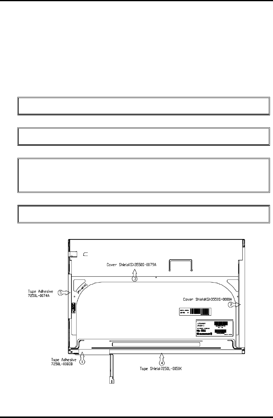
4.29 Fluorescent Lamp 4 Replacement Procedure
4.29.2 Replacing the 15.4-inch WXGA LG.Philips Fluorescent Lamp
Disassembly of outside tape / Cover shield
To disassemble the 15.4-inch WXGA LG.Philips fluorescent lamp, follow the steps below
and refer to figures 4-62 to 4-65.
1. Disassembly of Tape adhesive used for B/L Wire fixing
CAUTION: Pressure or stress should not be given on B/L Wire.
2. Disassembly of Tape adhesive used for B/L Wire fixing
CAUTION: Pressure or stress should not be given on Gate COF.
3. Disassembly of Cover shield (S)
CAUTION: Pressure or stress should not be given on Source PCB. Usage of gloves
with anti-electric discharge coating is recommended, to eliminate possible damage
on circuits occurred by ESC.
4. Disassembly of Tape shield and Tape Adhesive used for Top case fixing
CAUTION: Pressure or stress should not be given on Top case during this process.
Figure 4-62 Replacing LG.Philips fluorescent lamp (WXGA) (1)
Satellite M30-35 Maintenance Manual (960-455) 4-89
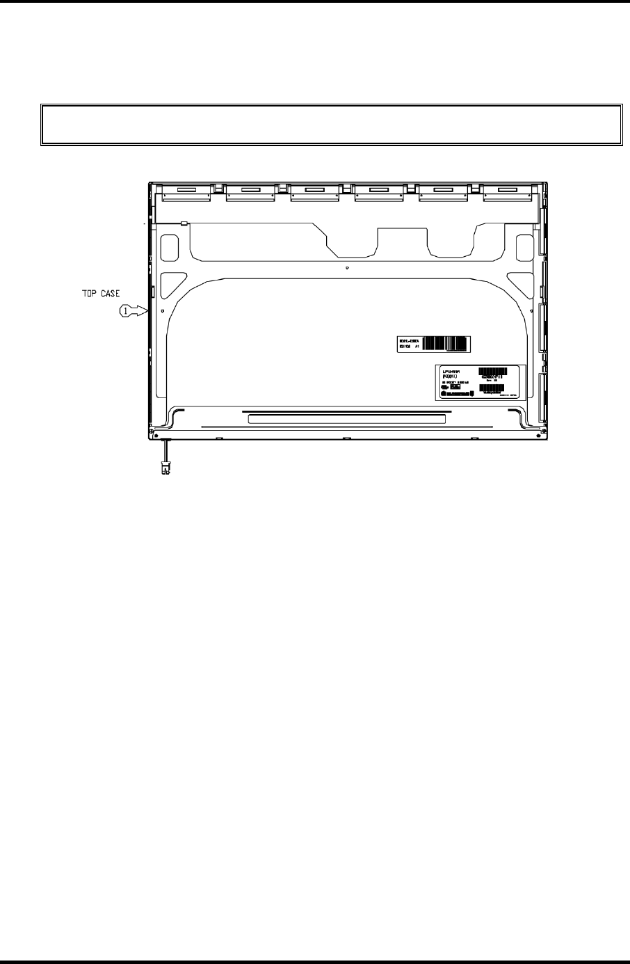
4 Replacement Procedure 4.29 Fluorescent Lamp
Disassembly of Top case
1. Disassembly of Top Case
CAUTION: Pressure or stress should not be given on Top Case and Gate COF.
Figure 4-63 Replacing LG.Philips fluorescent lamp (WXGA) (2)
4-90 Satellite M30-35 Maintenance Manual (960-455)
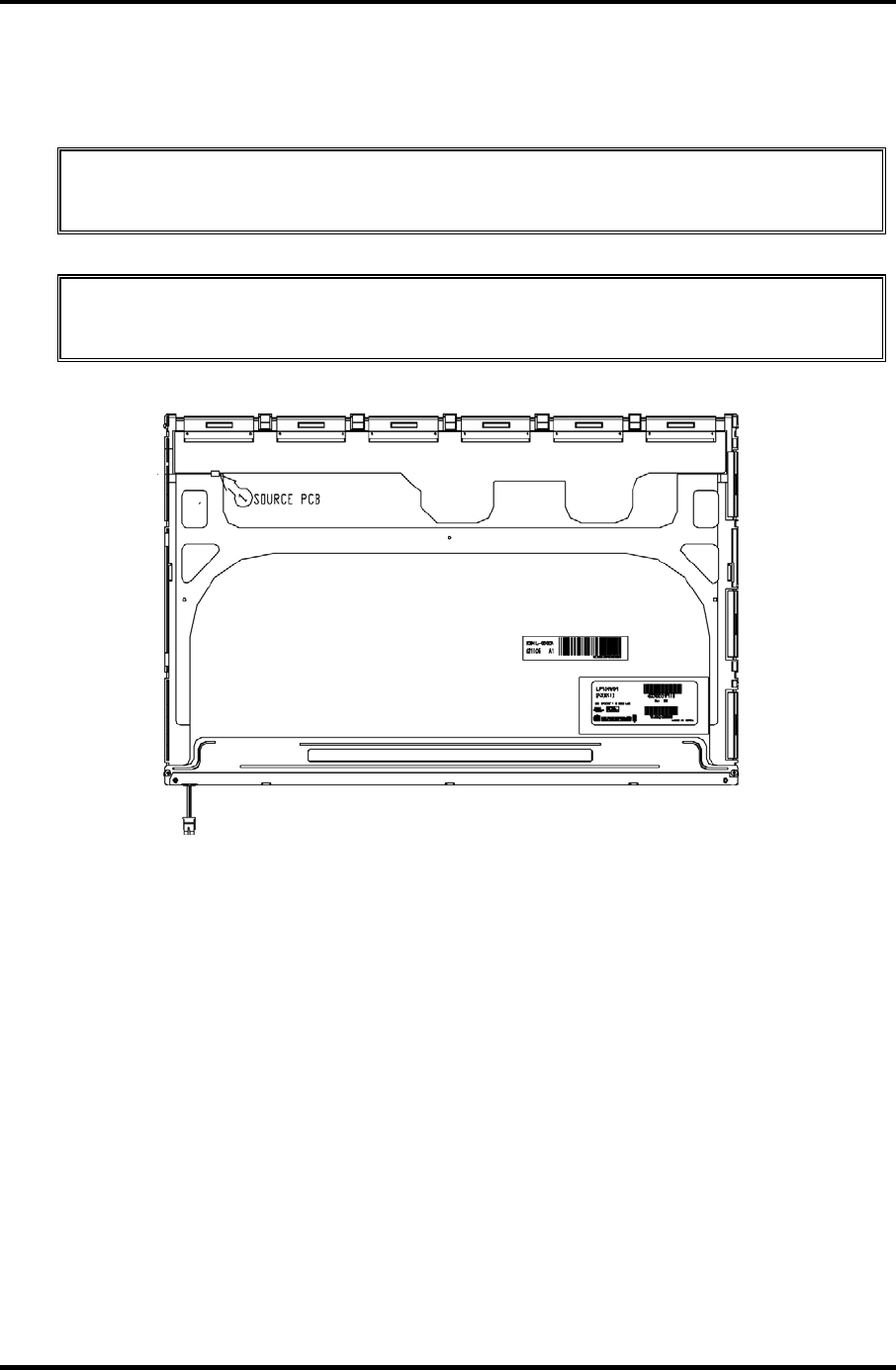
4.29 Fluorescent Lamp 4 Replacement Procedure
Disassembly of Source PCB and Gate PCB
1. Disassembly of Source PCB
CAUTION: Pressure or stress should not be given on PCB and TCP during
removing double tape.
2. Disassembly of Gate PCB
CAUTION: Pressure or stress should not be given on PCB and TCP during
removing double tape.
Figure 4-64 Replacing LG.Philips fluorescent lamp (WXGA) (3)
Satellite M30-35 Maintenance Manual (960-455) 4-91
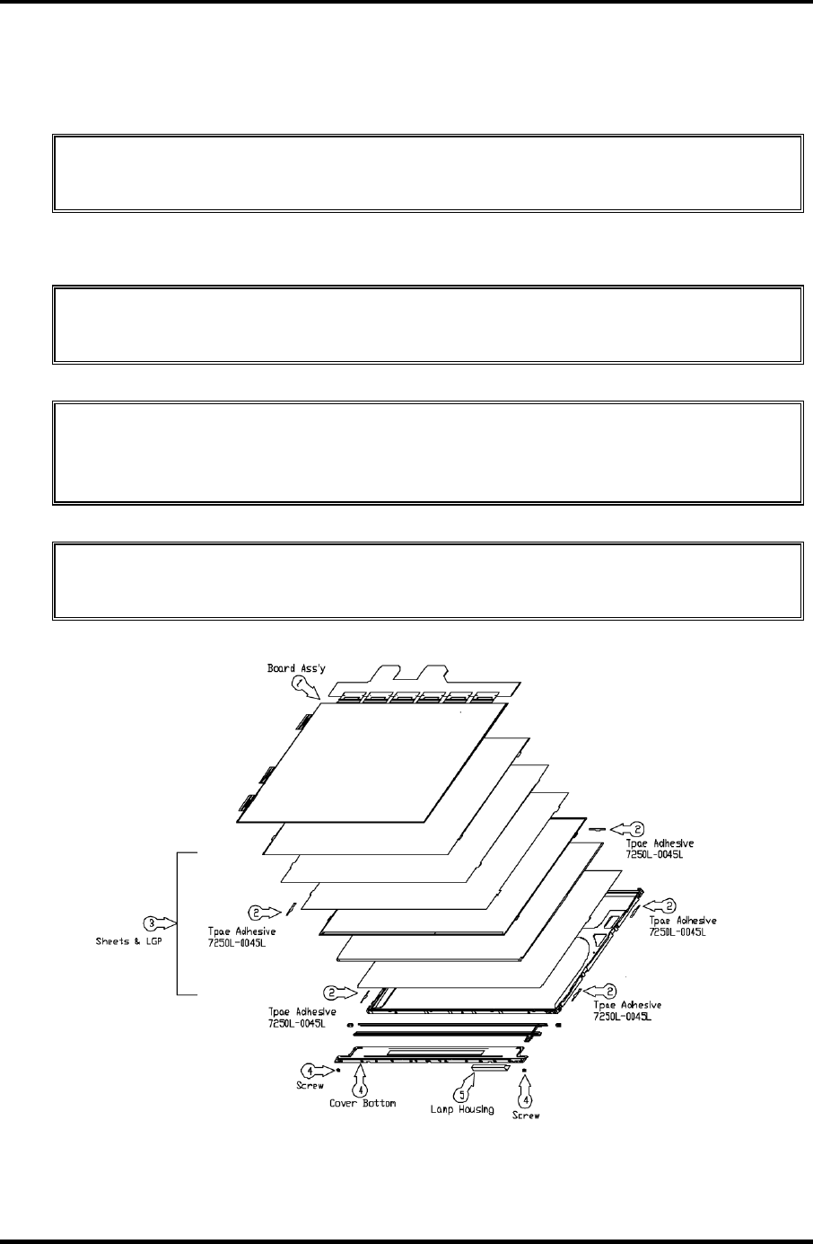
4 Replacement Procedure 4.29 Fluorescent Lamp
Disassembly of Board Ass’y, Tape Adhesive, Light guide,Cover Ass’y bottom (L)
1. Disassembly of Board Ass’y
CAUTION: This process should be made in Clean room with no scratch nor
particle on Polarizer and B/L Ass’y.
2. Disassembly of Tape Adhesive used for Sheets fixing (5Point).
3. Disassembly of Sheets, Light guide
CAUTION: No penetration of foreign body is indispensable with no scratch on the
surface of each sheet.
4. Disassembly of Screw and Cover bottom
CAUTION: Maximum value of torque with Screw should be below 3.0kgf·cm
pressure or stress should not be given on Lamp Housing during detaching double
tape.
5. Disassembly of Lamp Ass’y
CAUTION: Pressure or stress should not be given on Lamp Ass’y during detaching
double tape.
Figure 4-65 Replacing LG. LG.Philips fluorescent lamp (WXGA) (4)
4-92 Satellite M30-35 Maintenance Manual (960-455)
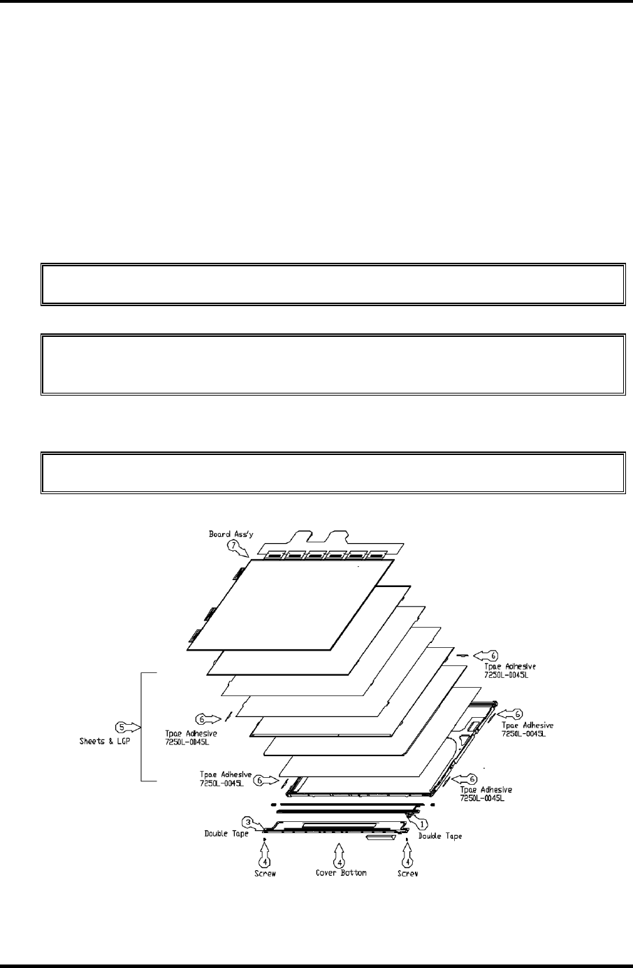
4.29 Fluorescent Lamp 4 Replacement Procedure
Assembly of Cover bottom, Sheets, Light guide, Tape Adhesive, Double Tape and
Board Ass’y.
To assemble the 15.4-inch WXGA LG.Philips fluorescent lamp, follow the steps below and
refer to figures 4-66 to 4-69.
1. Detach a protect film from Double Tape at the Lamp Ass’y.
2. Attach the Lamp Ass’y to the Support Main.
3. Detach a protect film from Double Tape at the inside of Cover Bottom.
4. Assemble the Cover Bottom and Screw to the Support Main.
CAUTION: Maximum value of torque with Screw should be below 3.0kgf·cm.
5. Assembly of Light Guide and Sheets.(Reflector Sheet fixing with one Double Tapes)
CAUTION: No penetration of foreign body is indispensable with no scratch on the
surface of each.
6. Assembly of Tape adhesive used for Sheets fixing (5Point)
7. Assembly of Board Ass’y
CAUTION: Pressure or stress should not be given on PCB and TCP.
Figure 4-66 Replacing LG.Philips fluorescent lamp (WXGA) (5)
Satellite M30-35 Maintenance Manual (960-455) 4-93
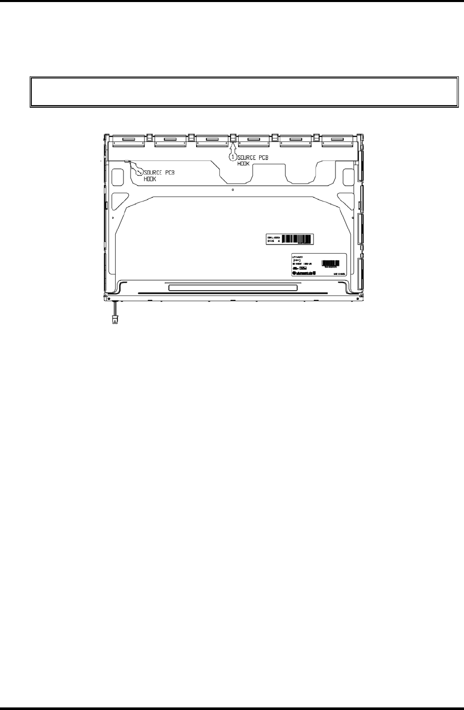
4 Replacement Procedure 4.29 Fluorescent Lamp
Assembly of Source PCB
1. Assembly of Source PCB
CAUTION: Stress should not be given on TCP during assembling S/M hook.
Figure 4-67 Replacing LG.Philips fluorescent lamp (WXGA) (6)
4-94 Satellite M30-35 Maintenance Manual (960-455)
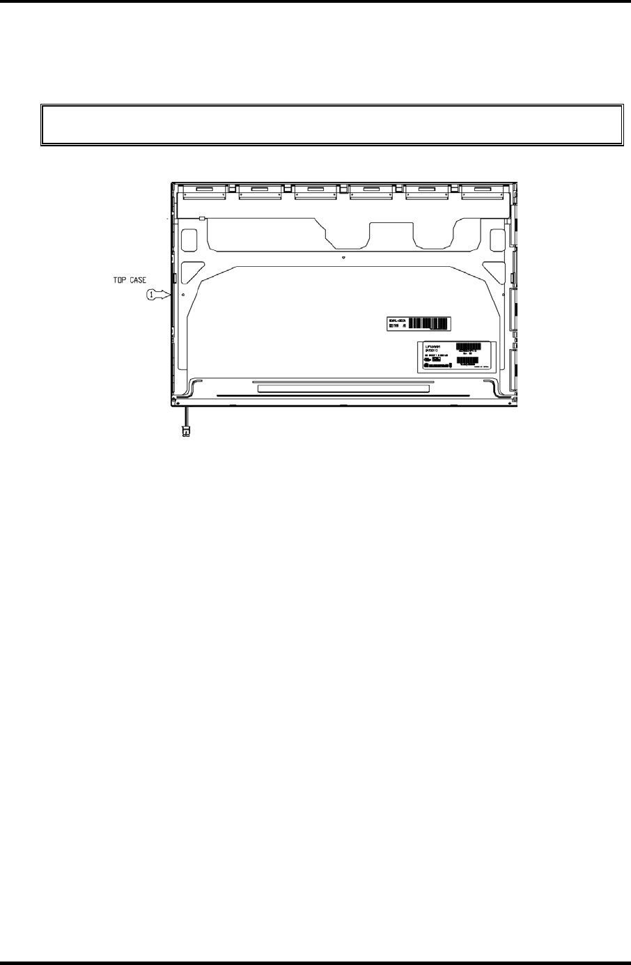
4.29 Fluorescent Lamp 4 Replacement Procedure
Assembly of Cover Ass’y, Screw, Top Case
1. Assembly of Top Case
CAUTION: Pressure should not be given on Gate COF.
Figure 4-68 Replacing LG.Philips fluorescent lamp (WXGA) (7)
Satellite M30-35 Maintenance Manual (960-455) 4-95
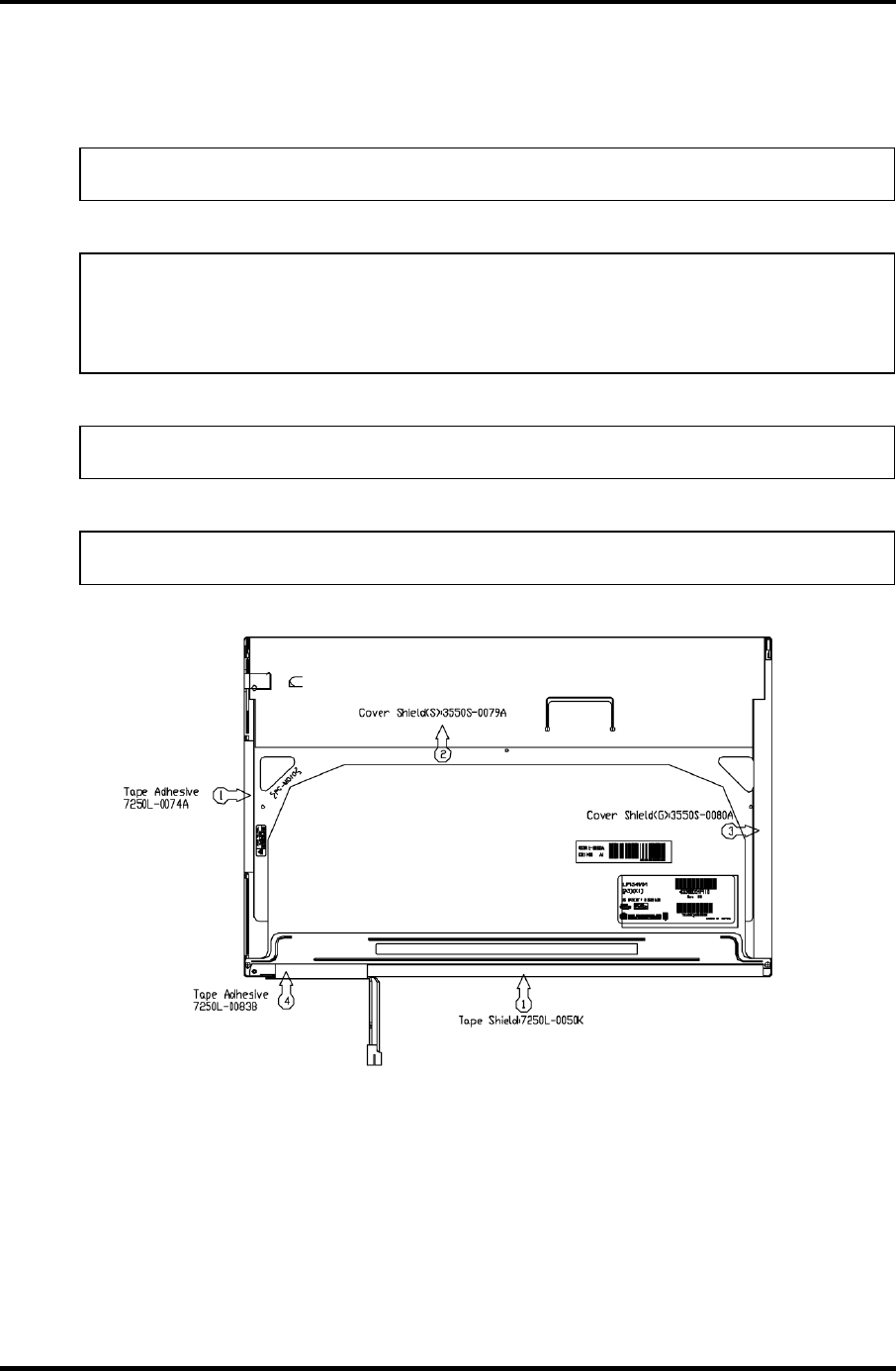
4 Replacement Procedure 4.29 Fluorescent Lamp
Assembly of outside Tape and Cover shield
1. Assembly of Tape shield and Tape Adhesive used for Top case fixing
NOTE: Pressure or stress should not be given on Top case during this process.
2. Assembly of Cover shield (S)
NOTE: Pressure or stress should not be given on control PCB.
Usage of gloves with anti-electric discharge coating is recommended to eliminate
possible damage on circuits occurred by ESC.
3. Assembly of Cover shield (G)
NOTE: Pressure or stress should not be given on Gate COF.
4. Assembly of Tape adhesive used for B/L Wire fixing
NOTE: Pressure or stress should not be given on B/L wire.
Figure 4-69 Replacing LG.Philips fluorescent lamp (WXGA) (8)
4-96 Satellite M30-35 Maintenance Manual (960-455)
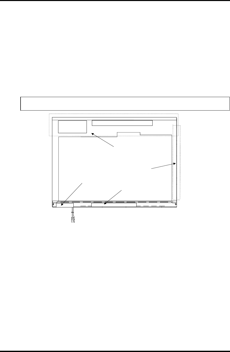
4.29 Fluorescent Lamp 4 Replacement Procedure
4.29.3 Replacing the 15.4-inch WXGA Samsung Fluorescent Lamp
Disassembling the 15.4-inch WXGA Samsung Fluorescent Lamp
To disassemble the 15.4-inch WXGA Samsung fluorescent lamp, follow the steps below and
refer to figures4-70 to 4-74.
1. Remove the PCB cover and COF cover.
2. Remove the lamp wire tape and Al tape.
NOTE: Be careful not to damage the COF of S/D or G/D ICs.
COF cover
PCB cover
A
l tape
Lamp wire tape
Figure 4-70 Replacing Samsung fluorescent lamp (WXGA) (1)
Satellite M30-35 Maintenance Manual (960-455) 4-97
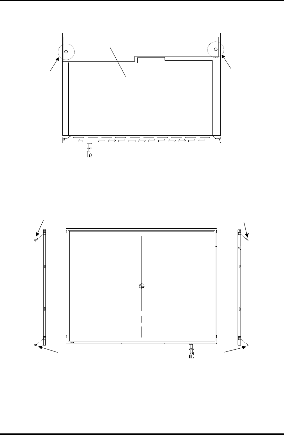
4 Replacement Procedure 4.29 Fluorescent Lamp
3. Remove the two screws from the PCB.
Screw
Screw
PCB
Figure 4-71 Replacing Samsung fluorescent lamp (WXGA) (2)
4. Remove the four screws from the top chassis.
Screw Screw
Screw Screw
Figure 4-72 Replacing Samsung fluorescent lamp (WXGA) (3)
4-98 Satellite M30-35 Maintenance Manual (960-455)
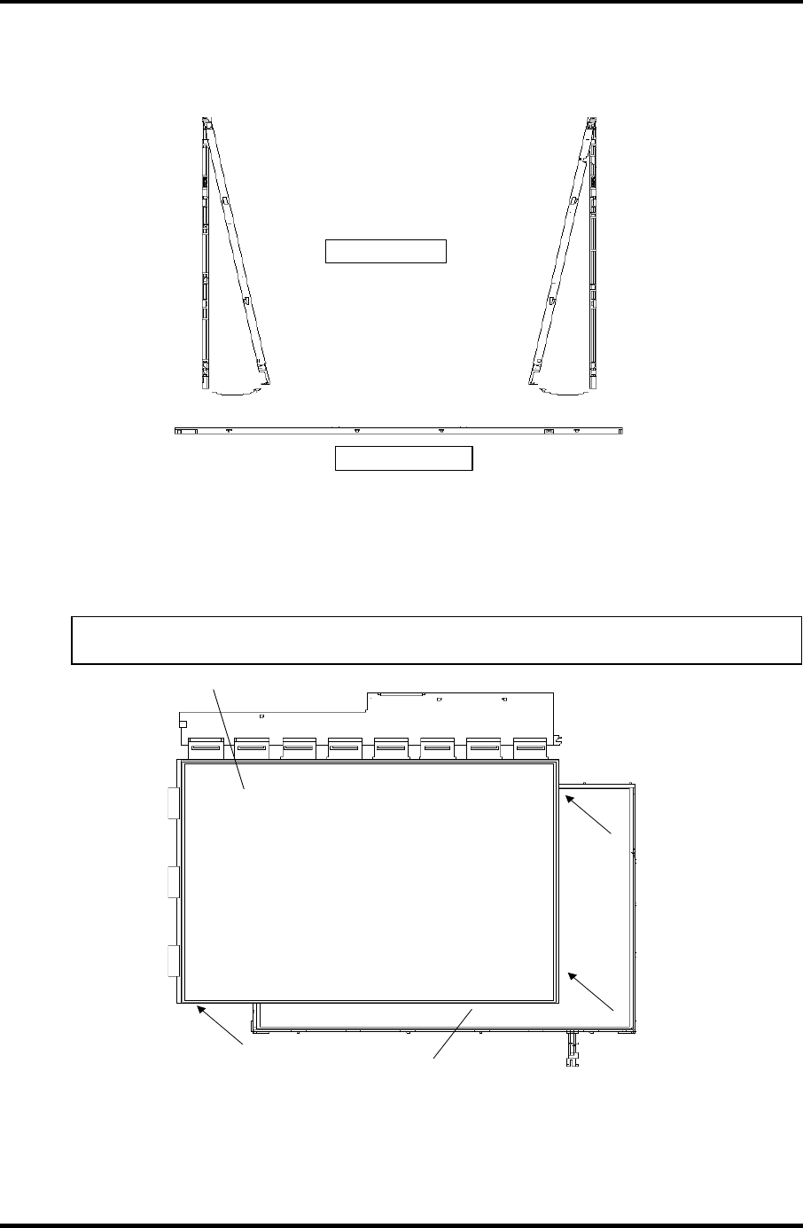
4.29 Fluorescent Lamp 4 Replacement Procedure
5. Remove the four bottom hooks and four side hooks (left and right) in the order. Then
remove the top chassis from the mold frame.
(2) Side hook
(1) B ottom hook
Figure 4-73 Replacing Samsung fluorescent lamp (WXGA) (4)
6. Remove the panel assembly from the BLU.
NOTE: Be careful not to damage the COF of S/D or G/D ICs.
Panel assembly
BLU
Figure 4-74 Replacing Samsung fluorescent lamp (WXGA) (5)
Satellite M30-35 Maintenance Manual (960-455) 4-99

4 Replacement Procedure 4.29 Fluorescent Lamp
4-100 Satellite M30-35 Maintenance Manual (960-455)
7. The assembly procedure of the 15.4-inch WXGA Samsung fluorescent lamp is the
reverse of the above disassembly procedure.

Appendices

Appendices
App-ii

Appendices
Appendix Contents
Appendix A Handling the LCD Module .......................................................................... A-1
Appendix B Board Layout .................................................................................................B-1
B.1 System Board (FMSSY* 32M) Front View...............................................................1
B.2 System Board (FMSSY* 32M) Back View ...............................................................3
B.3 System Board (FMSMP* 64M) Front View ..............................................................5
B.4 System Board (FMSMP* 64M) Back View ..............................................................7
Appendix C Pin Assignments............................................................................................ C-1
C.1 IS1400/1401 Memory connector (200-pin)...........................................................C-1
C.2 PJ1800 HDD I/F connector (44-pin).....................................................................C-4
C.3 PJ1820 CD-ROM I/F connector (50-pin)..............................................................C-5
C.4 PJ2100 PC card I/F connector (68-pin).................................................................C-6
C.5 IS2101 SD card I/F connector (12-pin).................................................................C-7
C.6 PJ2200 Mini PCI I/F connector (124-pin) ............................................................C-8
C.7 PJ3000 MDC I/F connector (30-pin) ..................................................................C-10
C.8 PJ3200 Keyboard I/F connector (34-pin)............................................................C-11
C.9 PJ3201 PAD I/F connector (8-pin)......................................................................C-11
C.10 PJ3400 Parallel I/F Connector (25-pin) ..............................................................C-12
C.11 PJ4100 Network I/F connector (14-pin)..............................................................C-12
C.12 PJ4200 1394 I/F connector (4-pin)......................................................................C-13
C.13 PJ5600 LCD connector (41-pin) .........................................................................C-13
C.14 PJ5621 CRT I/F connector (20-pin)....................................................................C-14
C.15 PJ6001 Internal Microphone connector (2-pin) ..................................................C-14
C.16 PJ6004 Speaker Connector (left) (2-pin) ............................................................C-14
C.17 PJ6003 Speaker Connector (right) (3-pin) ..........................................................C-15
C.18 PJ7000 CD key I/F connector (18-pin) ...............................................................C-15
C.19 PJ7001 Power switch I/F connector (15-pin)......................................................C-16
C.20 PJ7002 Sound connector PCB I/F connector (20-pin) ........................................C-16
C.21 PJ7004 Panel switch I/F connector (2-pin) .........................................................C-17
C.22 PJ8810 1st Battery connector (7-pin)..................................................................C-17
App-iii

Appendices
C.23 PJ8490 RTC Battery Connector (3-pin)..............................................................C-17
C.24 PJ8770 FAN connector (3-pin) ...........................................................................C-17
C.25 PJ2000 Debugging port (4-pin)...........................................................................C-18
C.26 PJ7003 USB connector PCB I/F connector (4-pin) ............................................C-19
C.27 PJ7003 USB connector PCB I/F connector 1 (4-pin) .........................................C-19
C.28 PJ7005 USB connector PCB I/F connector (2-pin) ............................................C-19
Appendix D Keyboard Scan/Character Codes................................................................ D-1
Appendix E Key Layout .....................................................................................................E-1
E.1 United Kingdom (UK) Keyboard...........................................................................E-1
E.2 United States (US) Keyboard.................................................................................E-1
Appendix F Wiring Diagrams ...........................................................................................F-1
F.1 Parallel Port Wraparound Connector ..................................................................... F-1
F.2 LAN Loopback Connector ..................................................................................... F-2
Appendix G BIOS Rewrite Procedures ........................................................................... G-1
Appendix H EC/KBC Rewrite Procedures...................................................................... H-1
Appendix I Reliability .........................................................................................................I-1
Appendix J SETUP ............................................................................................................. J-1
App-iv

Appendices
Figures
Figure B-1 System board (FMSSY* 32M) layout (front) ........................................................1
Figure B-2 System board (FMSSY* 32M) layout (back).........................................................3
Figure B-3 System board (FMSMP* 64M) layout (front)........................................................5
Figure B-4 System board (FMSMP* 64M) layout (back)........................................................7
Figure E-1 UK keyboard.......................................................................................................E-1
Figure E-2 US keyboard .......................................................................................................E-1
Figure F-1 Parallel port wraparound connector.................................................................... F-1
Figure F-2 LAN loopback connector.................................................................................... F-1
Figure J-1 Main menu............................................................................................................J-2
App-v

Appendices
Tables
Table B-1 System board (FMSSY* 32M) ICs and connectors (front) .....................................2
Table B-2 System board (FMSSY* 32M) ICs and connectors (back) .....................................4
Table B-3 System board (FMSMP* 64M) ICs and connectors (front) ....................................6
Table B-4 System board (FMSMP* 64M) ICs and connectors (back).....................................8
Table C-1 Memory connector (200-pin)...............................................................................C-1
Table C-2 HDD I/F connector (44-pin) ................................................................................C-4
Table C-3 CD-ROM I/F connector (50-pin).........................................................................C-5
Table C-4 PC card I/F connector (68-pin) ............................................................................C-6
Table C-5 SD card I/F connector (12-pin)............................................................................C-7
Table C-6 Mini PCI I/F connector (124-pin)........................................................................C-8
Table C-7 MDC I/F connector (300-pin)............................................................................C-10
Table C-8 Keyboard I/F connector (34-pin) .......................................................................C-11
Table C-9 PAD I/F connector (8-pin).................................................................................C-11
Table C-10 Parallel I/F Connector (25-pin)........................................................................C-12
Table C-11 Network I/F connector (14-pin).......................................................................C-12
Table C-12 1394 I/F connector (4-pin)...............................................................................C-13
Table C-13 LCD connector (41-pin) ..................................................................................C-13
Table C-14 CRT I/F connector (20-pin) .............................................................................C-14
Table C-15 Internal Microphone connector (2-pin) ...........................................................C-14
Table C-16 Speaker Connector (left) (2-pin)......................................................................C-14
Table C-17 Speaker Connector (right) (3-pin) ...................................................................C-15
Table C-18 CD key I/F connector (18-pin) ........................................................................C-15
Table C-19 Power switch I/F connector (15-pin) ...............................................................C-16
Table C-20 Sound connector PCB I/F connector (20-pin) .................................................C-16
Table C-21 Panel switch I/F connector (2-pin) ..................................................................C-17
Table C-22 1st Battery connector (7-pin) ...........................................................................C-17
Table C-23 PJ8490 RTC Battery Connector (3-pin) ..........................................................C-17
App-vi

Appendices
Table C-24 FAN connector (3-pin) ....................................................................................C-17
Table C-25 Debugging port (4-pin) ....................................................................................C-18
Table C-26 USB connector PCB I/F connector (4-pin)......................................................C-19
Table C-27 USB connector PCB I/F connector 1 (4-pin)...................................................C-19
Table C-28 USB connector PCB I/F connector 2 (2-pin)...................................................C-19
Table D-1 Scan codes (set 1 and set 2) ............................................................................... D-1
Table D-2 Scan codes with left Shift key ............................................................................ D-5
Table D-3 Scan codes in Numlock mode ............................................................................ D-6
Table D-4 Scan codes with Fn key ...................................................................................... D-6
Table D-5 Scan codes in overlay mode ............................................................................... D-7
Table D-6 No.124 key scan code......................................................................................... D-7
Table D-7 No.126 key scan code......................................................................................... D-8
Table I-1 MTBF..............................................................................................................I-1
App-vii

Appendices
App-viii
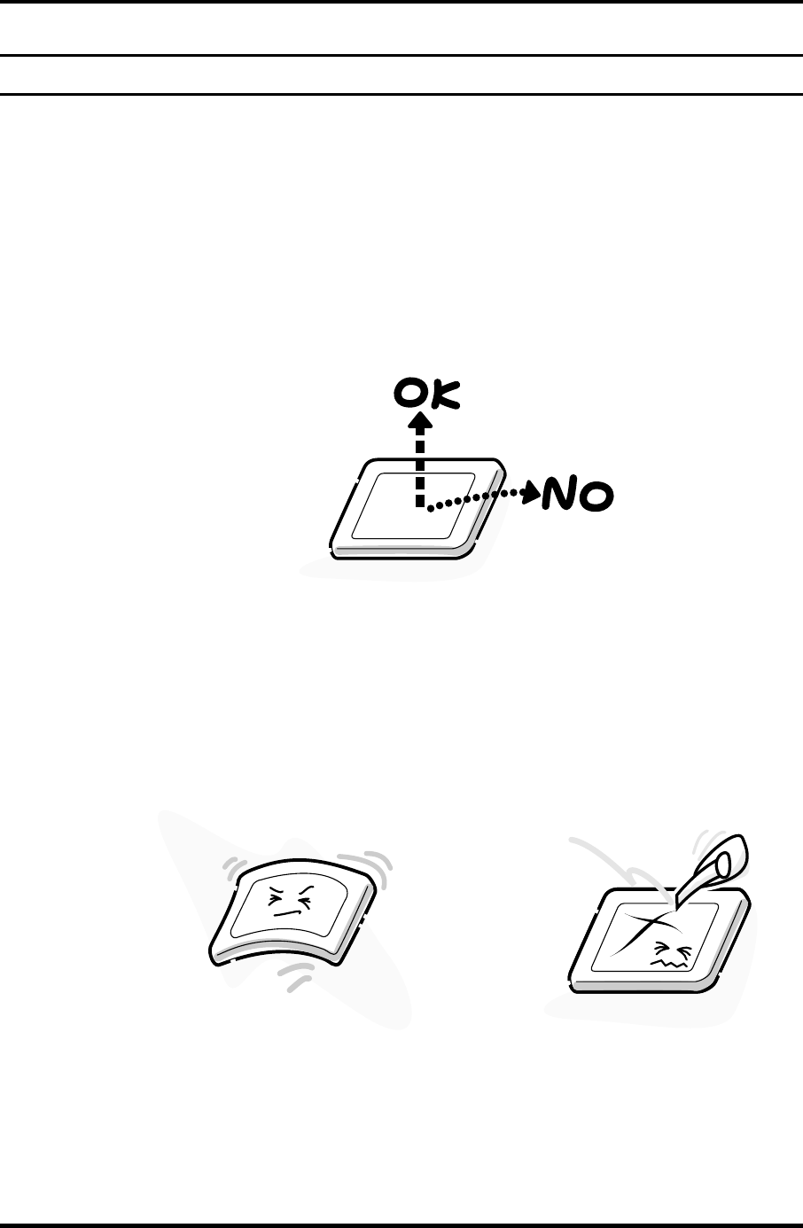
Appendix A Handling the LCD Module Appendices
Appendix A P
Appendix A Handling the LCD Module
Precautions for handling the LCD module
The LCD module can be easily damaged during assembly or disassembly. Observe the
following precautions when handling the LCD module:
1. When installing the LCD module in the LCD cover, be sure to seat it so that it is
properly aligned and maximum visibility of the display is maintained.
2. For 14.4 inch LCD module, be careful to align the four holes at the right side and left
side of the LCD module with the corresponding holes in the LCD cover before
securing the module with four screws.
Do not force the module into place, because stress can affect its performance.
Also, the panel’s polarized surface is easily scarred, so be carefully when handling it.
Satellite M30-35 Maintenance Manual (960-455) A-1
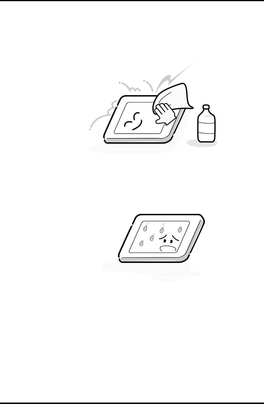
Appendices Appendix A Handling the LCD Module
3. If the panel’s surface gets dirty, wipe it with cotton or a soft cloth. If it is still dirty,
try breathing on the surface to create a light condensate and wipe it again.
If the surface is very dirty, we recommend a CRT cleaning agent. Apply the agent to
a cloth and then wipe the panel’s surface. Do not apply cleanser directly to the panel.
CRT
Cleaner
4. If water or other liquid is left on the panel’s surface for a long period, it can change
the screen’s tint or stain it. Be sure to quickly wipe off any liquid.
A-2 Satellite M30-35 Maintenance Manual (960-455)

Appendix A Handling the LCD Module Appendices
5. Glass is used in the panel, so be careful not to drop it or let it strike a hard object,
which could cause breakage or cracks.
6. CMOS-LSI circuits are used in the module, so guard against damage from
electrostatic discharge. Be sure to wear a wrist or ankle ground when handling the
module.
Satellite M30-35 Maintenance Manual (960-455) A-3
Appendices Appendix A Handling the LCD Module
7. Do not expose the module to direct sunlight or strong ultraviolet rays for long
periods.
8. Do not store the module at temperatures below specifications. Cold can cause the
liquid crystals to freeze, lose their elasticity or otherwise suffer damage.
A-4 Satellite M30-35 Maintenance Manual (960-455)
Appendix A Handling the LCD Module Appendices
9. Do not disassemble the LCD module. Disassembly can cause malfunctions.
10. If you transport the module, do not use packing material that contains epoxy resin
(amine) or silicon glue (alcohol or oxime). These materials can release gas that can
damage the panel’s polarization.
Satellite M30-35 Maintenance Manual (960-455) A-5

Appendices Appendix A Handling the LCD Module
A-6 Satellite M30-35 Maintenance Manual (960-455)
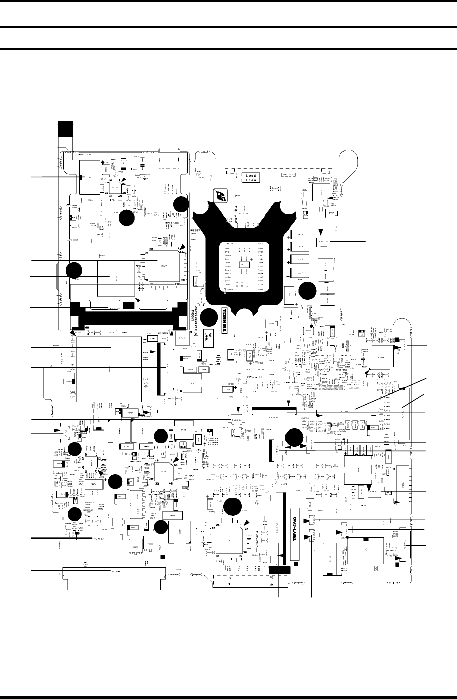
Appendix B Board Layout Appendices
Appendix B Board Layout
B.1 System Board (FMSSY* 32M) Front View
(A)
(B)
(C)
(D)
(E)
(F)
(G) (H)
(I)
(J)
(K)
(L)
(M)
(N)
(O)
(P)
(Q)
(R)
(S)
(T)
(U)
(V)
(W)
Figure B-1 System board (FMSSY* 32M) layout (front)
Satellite M30-35 Maintenance Manual (960-455) B-1
Appendices Appendix B Board Layout
Table B-1 System board (FMSSY* 32M) ICs and connectors (front)
Mark Number Name
(A) PJ2100 PC card I/F connector
(B) PJ7000 CD key I/F connector
(C) PJ6001 Internal microphone I/F connector
(D) PJ8490 RTC battery connector
(E) PJ7002 Sound connector PCB I/F connector
(F) PJ1800 HDD I/F connector
(G) PJ3200 Keyboard I/F connector
(H) PJ6003 Speaker connector (right)
(I) PJ4100 Network I/F connector
(J) PJ7003 USB connector PCB I/F connector
(K) PJ6004 Speaker connector (left)
(L) PJ8810 1st battery connector
(M) PJ3201 PAD I/F connector
(N) PJ7004 Panel switch I/F connector
(0) PJ7001 Power switch I/F connector
(P) PJ5621 CRT I/F connector
(Q) PJ8770 FAN connector
(R) PJ2000 Debugging port
(S) IC3200 EC/KBC
(T) IC2000 YEBISUSS
(U) IC1600 ICH4-M
(V) IC3001 FWH
(W) PJ5600 LCD I/F connector
B-2 Satellite M30-35 Maintenance Manual (960-455)
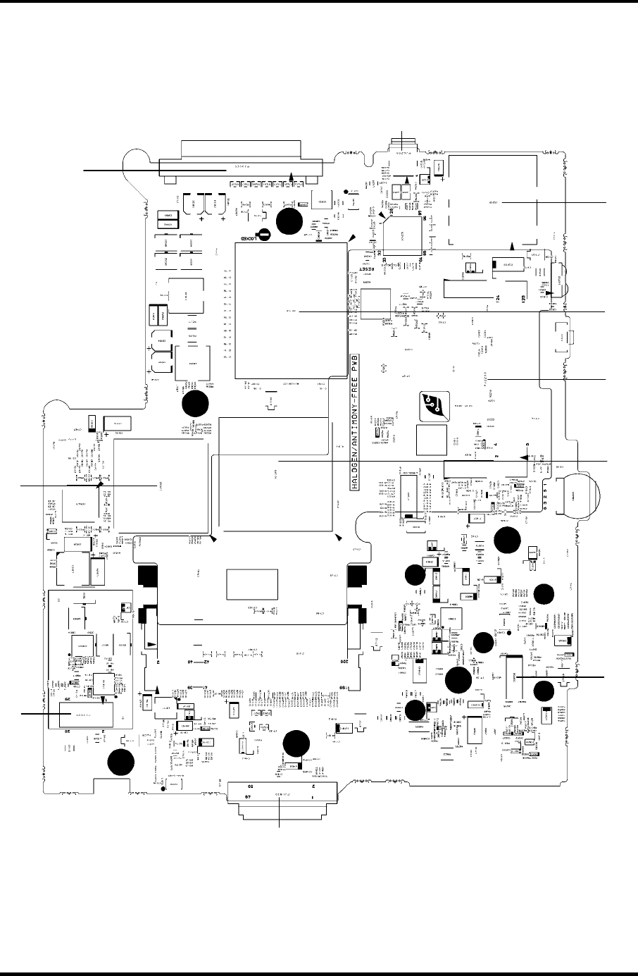
Appendix B Board Layout Appendices
B.2 System Board (FMSSY* 32M) Back View
(A)
(B)
(C)
(D)
(E)
(F)
(G)
(H)
(I)
(J)
Figure B-2 System board (FMSSY* 32M) layout (back)
Satellite M30-35 Maintenance Manual (960-455) B-3
Appendices Appendix B Board Layout
Table B-2 System board (FMSSY* 32M) ICs and connectors (back)
Mark Number Name
(A) PJ3400 Parallel I/F connector
(B) PJ3000 MDC I/F connector
(C) PJ1820 CD-ROM I/F connector
(D) PJ2200 Mini PCI I/F connector
(E) PJ4200 1394 I/F connector
(F) IC5000 NV34
(G) IC1200 MCH-M
(H) IS1100 CPU
(I) IC6008 AN12940
(J) IS2101 SD card I/F connector
B-4 Satellite M30-35 Maintenance Manual (960-455)
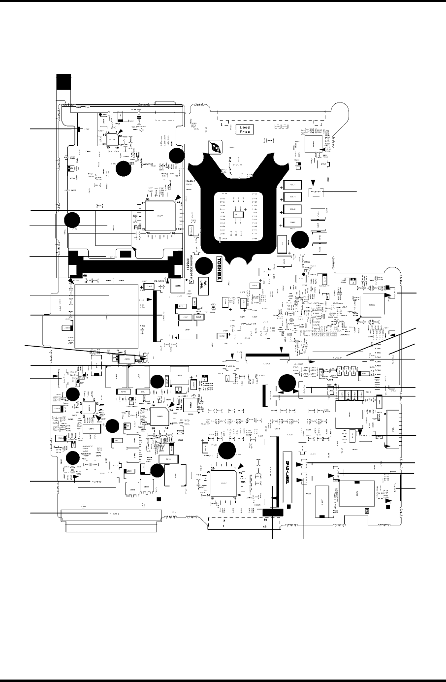
Appendix B Board Layout Appendices
B.3 System Board (FMSMP* 64M) Front View
(A)
(B)
(C)
(D)
(E)
(F)
(G) (H)
(I)
(J)
(K)
(L)
(M)
(N)
(O)
(P)
(Q)
(R)
(S)
(T)
(U)
(V)
(W)
(X)
Figure B-3 System board (FMSMP* 64M) layout (front)
Satellite M30-35 Maintenance Manual (960-455) B-5
Appendices Appendix B Board Layout
Table B-3 System board (FMSMP* 64M) ICs and connectors (front)
Mark Number Name
(A) PJ2100 PC card I/F connector
(B) PJ7000 CD key I/F connector
(C) PJ6001 Internal microphone I/F connector
(D) PJ8490 RTC battery connector
(E) PJ7002 Sound connector PCB I/F connector
(F) PJ1800 HDD I/F connector
(G) PJ3200 Keyboard I/F connector
(H) PJ6003 Speaker connector (right)
(I) PJ4100 Network I/F connector
(J) PJ7003 USB connector PCB I/F connector 1
(K) PJ6004 Speaker connector (left)
(L) PJ8810 1st battery connector
(M) PJ3201 PAD I/F connector
(N) PJ7004 Panel switch I/F connector
(0) PJ7001 Power switch I/F connector
(P) PJ5621 CRT I/F connector
(Q) PJ8770 FAN connector
(R) PJ2000 Debugging port
(S) IC3200 EC/KBC
(T) IC2000 YEBISUSS
(U) IC1600 ICH4-M
(V) IC3001 FWH
(W) PJ5600 LCD I/F connector
(X) PJ7005 USB connector PCB I/F connector 2
B-6 Satellite M30-35 Maintenance Manual (960-455)

Appendix B Board Layout Appendices
B.4 System Board (FMSMP* 64M) Back View
(A)
(B)
(C)
(D)
(E)
(F)
(G)
(H)
(I)
(J)
Figure B-4 System board (FMSMP* 64M) layout (back)
Satellite M30-35 Maintenance Manual (960-455) B-7

Appendices Appendix B Board Layout
B-8 Satellite M30-35 Maintenance Manual (960-455)
Table B-4 System board (FMSMP* 64M) ICs and connectors (back)
Mark Number Name
(A) PJ3400 Parallel I/F connector
(B) PJ3000 MDC I/F connector
(C) PJ1820 CD-ROM I/F connector
(D) PJ2200 Mini PCI I/F connector
(E) PJ4200 1394 I/F connector
(F) IC5000 NV64
(G) IC1200 MCH-M
(H) IS1100 CPU
(I) IC6008 AN12940
(J) IS2101 SD card I/F connector
Appendix C Pin Assignment Appendices
Satellite M30-35 Maintenance Manual (960-455) C-1
C
Appendix C Pin Assignment
System Board (common to FMSSY* 32M, FMSMP* 64M)
C.1 IS1400/1401 Memory connector (200-pin)
Table C-1 Memory connector (200-pin)(1/4)
Pin No. Signal name I/O Pin No. Signal name I/O
1 VREF - 2 VREF -
3 GND - 4 GND -
5 SDQ00R-B2P I/O 6 SDQ06R-B2P I/O
7 SDQ04R-B2P I/O 8 SDQ01R-B2P I/O
9 2R5-B2V - 10 2R5-B2V -
11 SDQS0R-B2P I/O 12 GND -
13 SDQ05R-B2P I/O 14 SDQ02R-B2P I/O
15 GND - 16 GND -
17 SDQ03R-B2P I/O 18 SDQ07R-B2P I/O
19 SDQ13R-B2P I/O 20 SDQ12R-B2P I/O
21 2R5-B2V - 22 2R5-B2V -
23 SDQ08R-B2P I/O 24 SDQ09R-B2P I/O
25 SDQS1R-B2P I/O 26 GND -
27 GND - 28 GND -
29 SDQ14R-B2P I/O 30 SDQ11R-B2P I/O
31 SDQ15R-B2P I/O 32 SDQ10R-B2P I/O
33 2R5-B2V - 34 2R5-B2V -
35 SCK0-B2P I 36 2R5-B2V -
37 SCK0-B2N I 38 GND -
39 GND - 40 GND -
41 SDQ20R-B2P I/O 42 SDQ22R-B2P I/O
43 SDQ16R-B2P I/O 44 SDQ21R-B2P I/O
45 2R5-B2V - 46 2R5-B2V -
47 SDQS2R-B2P I/O 48 GND -
49 SDQ17R-B2P I/O 50 SDQ19R-B2P I/O
51 GND - 52 GND -
53 SDQ18R-B2P I/O 54 SDQ23R-B2P I/O
Appendices Appendix C Pin Assignment
C-2 Satellite M30-35 Maintenance Manual (960-455)
Table C-1 Memory connector (200-pin)(2/4)
Pin No. Signal name I/O Pin No. Signal name I/O
55 SDQ25R-B2P I/O 56 SDQ29R-B2P I/O
57 2R5-B2V - 58 2R5-B2V -
59 SDQ24R-B2P I/O 60 SDQ28R-B2P I/O
61 SDQS3R-B2P I/O 62 GND -
63 GND - 64 GND -
65 SDQ26R-B2P I/O 66 SDQ30R-B2P I/O
67 SDQ27R-B2P I/O 68 SDQ31R-B2P I/O
69 2R5-B2V - 70 2R5-B2V -
71 SCB5A-B2P I/O 72 SCB0A-B2P I/O
73 SCB4A-B2P I/O 74 SCB1A-B2P I/O
75 GND - 76 GND -
77 SDQS8A-B2P I/O 78 GND -
79 SCB2A-B2P I/O 80 SCB3A-B2P I/O
81 2R5-B2V - 82 2R5-B2V -
83 SCB6A-B2P I/O 84 SCB7A-B2P I/O
85 N.C - 86 N.C -
87 GND - 88 GND -
89 2R5-B2V - 90 GND -
91 GND - 92 2R5-B2V -
93 2R5-B2V - 94 2R5-B2V -
95 SCKE1-B2P I 96 SCKEO-B2P I
97 N.C - 98 N.C -
99 SMA12R-B2P I 100 SMA11R-B2P I
101 SMA09R-B2P I 102 SMA08R-B2P I
103 GND - 104 GND -
105 SMA07R-B2P I 106 SMA06R-B2P I
107 SMA05R-B2P I 108 SMA04R-B2P I
109 SMA03R-B2P I 110 SMA02R-B2P I
111 SMA01R-B2P I 112 SMA00R-B2P I
113 2R5-B2V - 114 2R5-B2V -
115 SMA10R-B2P I 116 SBS1R-B2P I
117 SBS0R-B2P I 118 SRASR-B2N I
119 SWER-B2N I 120 SCASR-B2N I
121 SCS0-B2N I 122 SCS1-B2N I
123 N.C - 124 N.C -
Appendix C Pin Assignment Appendices
Satellite M30-35 Maintenance Manual (960-455) C-3
Table C-1 Memory connector (200-pin)(3/4)
Pin No. Signal name I/O Pin No. Signal name I/O
125 GND - 126 GND -
127 SDQ37R-B2P I/O 128 SDQ33R-B2P I/O
129 SDQ36R-B2P I/O 130 SDQ32R-B2P I/O
131 2R5-B2V - 132 2R5-B2V -
133 SDQS4R-B2P I/O 134 GND -
135 SDQ34R-B2P I/O 136 SDQ39R-B2P I/O
137 GND - 138 GND -
139 SDQ38R-B2P I/O 140 SDQ35R-B2P I/O
141 SDQ44R-B2P I/O 142 SDQ41R-B2P I/O
143 2R5-B2V - 144 2R5-B2V -
145 SDQ45R-B2P I/O 146 SDQ40R-B2P I/O
147 SDQS5R-B2P I/O 148 GND -
149 GND - 150 GND -
151 SDQ46R-B2P I/O 152 SDQ47R-B2P I/O
153 SDQ42R-B2P I/O 154 SDQ43R-B2P I/O
155 2R5-B2V - 156 2R5-B2V -
157 2R5-B2V - 158 SCK1-B2N I
159 GND - 160 SCK1-B2P I
161 GND - 162 GND -
163 SDQ48R-B2P I/O 164 SDQ54R-B2P I/O
165 SDQ53R-B2P I/O 166 SDQ49R-B2P I/O
167 2R5-B2V - 168 2R5-B2V -
169 SDQS6R-B2P I/O 170 GND -
171 SDQ51-B2P I/O 172 SDQ50R-B2P I/O
173 GND - 174 GND -
175 SDQ52R-B2P I/O 176 SDQ55R-B2P I/O
177 SDQ60R-B2P I/O 178 SDQ57R-B2P I/O
179 2R5-B2V - 180 2R5-B2V -
181 SDQ56R-B2P I/O 182 SDQ61R-B2P I/O
183 SDQS7R-B2P I/O 184 GND I/O
185 GND - 186 GND -
187 SDQ58R-B2P I/O 188 SDQ63R-B2P I/O
189 SDQ59R-B2P I/O 190 SDQ62R-B2P I/O
191 2R5-B2V - 192 2R5-B2V -
193 SMBDAT-P3P I/O 194 GND -
Appendices Appendix C Pin Assignment
C-4 Satellite M30-35 Maintenance Manual (960-455)
Table C-1 Memory connector (200-pin)(4/4)
Pin No. Signal name I/O Pin No. Signal name I/O
195 SMBCLK-P3P I/O 196 GND -
197 P3V - 198 GND -
199 N.C - 200 N.C -
C.2 PJ1800 HDD I/F connector (44-pin)
Table C-2 HDD I/F connector (44-pin)
Pin No. Signal name I/O Pin No. Signal name I/O
1 IDRSTA-P5N I 2 GND -
3 PDD07-P3P I 4 PDD08-P3P O
5 PDD06-P3P I 6 PDD09-P3P O
7 PDD05-P3P I 8 PDD10-P3P O
9 PDD04-P3P I 10 PDD11-P3P O
11 PDD03-P3P I 12 PDD12-P3P O
13 PDD02-P3P I 14 PDD13-P3P O
15 PDD01-P3P I 16 PDD14-P3P O
17 PDD00-P3P I 18 PDD15-P3P O
19 GND - 20 N.C -
21 PDDREQ-P3P I 22 GND -
23 PDIOW-P3N I 24 GND -
25 PDIOR-P3N I 26 GND -
27 PIORDY-P3P I 28 GND -
29 PDDACK-P3N I 30 GND -
31 PDIRQ-P3P I 32 N.C -
33 PDA1-P3P I 34 N.C -
35 PDA0-P3P I 36 PDA2-P3P O
37 PDCS1-P3N I 38 PDCS3-P3N O
39 HDDLED-P5N I 40 GND -
41 P5V - 42 P5V -
43 GND - 44 N.C -
Appendix C Pin Assignment Appendices
Satellite M30-35 Maintenance Manual (960-455) C-5
C.3 PJ1820 CD-ROM I/F connector (50-pin)
Table C-3 CD-ROM I/F connector (50-pin)
Pin No. Signal name I/O Pin No. Signal name I/O
1 CDAUDL-EXP I 2 CDAUDR-EXP I
3 CD-GND I 4 N.C -
5 IDRSTB-E5N O 6 SDD08-E5P I/O
7 SDD07-E5P I/O 8 SDD09-E5P I/O
9 SDD06-E5P I/O 10 SDD10-E5P I/O
11 SDD05-E5P I/O 12 SDD11-E5P I/O
13 SDD04-E5P I/O 14 SDD12-E5P I/O
15 SDD03-E5P I/O 16 SDD13-E5P I/O
17 SDD02-E5P I/O 18 SDD14-E5P I/O
19 SDD01-E5P I/O 20 SDD15-E5P I/O
21 SDD00-E5P I/O 22 SDDREQ-E5P I
23 GND - 24 SDIOR-E3N O
25 SDIOW-E3N O 26 GND -
27 SIORDY-E5P I 28 SDDACK-E3N O
29 IRQ15-E5P I 30 N.C -
31 SDA1-E3P O 32 N.C O
33 SDA0-E3P O 34 SDA2-E3P O
35 SDCS1-E3N O 36 SDCS3-E3N O
37 SDASP-E5N I/O 38 CD-E5V O
39 CD-E5V I 40 CD-E5V O
41 CD-E5V I 42 CD-E5V O
43 GND - 44 GND -
45 GND - 46 N.C -
47 N.C - 48 GND -
49 N.C - 50 N.C -

Appendices Appendix C Pin Assignment
C-6 Satellite M30-35 Maintenance Manual (960-455)
C.4 PJ2100 PC card I/F connector (68-pin)
Table C-4 PC card I/F connector (68-pin) (1/2)
Pin No. Signal name I/O Pin No. Signal name I/O
1 GND - 2 ACAD00-BYP I/O
3 ACAD01-BYP I/O 4 ACAD03-BYP I/O
5 ACAD05-BYP I/O 6 ACAD07-BYP I/O
7 ACCBEO-BYP I/O 8 ACAD09-BYP I/O
9 ACAD11-BYP I/O 10 ACAD12-BYP I/O
11 ACAD14-BYP I/O 12 ACCBE1-BYN I/O
13 ACPAB-BYP I/O 14 ACRERR-BYN I/O
15 ACGNT-BYN I/O 16 ACTNT-BYN I/O
17 MCVCCA I/O 18 MCVPPA I/O
19 ACCLK-BYP I/O 20 ACTBDY-BYN I/O
21 ACCBE2-BYN I/O 22 ACAD18-BYP I/O
23 ACAD20-BYP I/O 24 ACAD21-BYP I/O
25 ACAD22-BYP I/O 26 ACAD23-BYP I/O
27 ACAD24-BYP I/O 28 ACAD25-BYP I/O
29 ACAD25-BYP I/O 30 ACAD27-BYP I/O
31 ACAD29-BYP I/O 32 ACD02-BYP I/O
33 ACCLKR-BYN I/O 34 GND -
35 GND - 36 ACCD1-B3N I/O
37 ACAD02-BYP I/O 38 ACAD04-BYP I/O
39 ACAD06-BYP I/O 40 ACD14-BYP I/O
41 ACAD08-BYP I/O 42 ACAD10-BYP I/O
43 ACVS1-B3P I/O 44 ACAD13-BYP I/O
45 ACAD15-BYP I/O 46 ACAD16-BYP I/O
47 ACA18-BYP I/O 48 ACLOCK-BYN I/O
49 ACSTOP-BYN I/O 50 ACDEVS-BYN I/O
51 MCVCCA I 52 MCVPPA I/O
53 ACTRDY-BYN I/O 54 ACFRAM-BYN I/O
55 ACAD17-BYP I/O 56 ACAD19-BYP I/O
57 ACYS2-B3P I/O 58 ACRST-BYN I/O
Appendix C Pin Assignment Appendices
Satellite M30-35 Maintenance Manual (960-455) C-7
Table C- PC card I/F connector (68-pin) (2/2)
Pin No. Signal name I/O Pin No. Signal name I/O
59 ACSERR-BYN I/O 60 ACREQ-BYN I/O
61 ACCBE3-BYN I/O 62 ACAUDI-BYP I
63 ACSTSC-BYP I 64 ACAD28-BYP I/O
65 ACAD30-BYP I/O 66 ACAD31-BYP I/O
67 ACCD2-B3N I 68 GND -
C.5 IS2101 SD card I/F connector (12-pin)
Table C-5 SD card I/F connector (12-pin)
Pin No. Signal name I/O Pin No. Signal name I/O
1 SDAT3-B3P I/O 2 SDCMD-B3P I/O
3 GND - 4 SD-B3V -
5 SDCLK-B3P O 6 GND -
7 SDAT0-B3P I/O 8 SDAT1-B3P I/O
9 SDAT2-B3P I/O 10 SDCD-B3N I
11 GND - 12 SDWP-B3P -
Appendices Appendix C Pin Assignment
C-8 Satellite M30-35 Maintenance Manual (960-455)
C.6 PJ2200 Mini PCI I/F connector (124-pin)
Table C-6 Mini PCI I/F connector (124-pin) (1/2)
Pin No. Signal name I/O Pin No. Signal name I/O
1 N.C. - 2 N.C. -
3 N.C. - 4 N.C. -
5 N.C. - 6 N.C. -
7 N.C. - 8 N.C. -
9 N.C. - 10 N.C. -
11 N.C. - 12 N.C. -
13 WLON-S3N I 14 N.C. -
15 GND - 16 N.C. -
17 PIRQA-P3N I 18 P5V -
19 P3V - 20 PIRQD-P3N O
21 N.C. - 22 N.C. -
23 GND - 24 B3V -
25 X33MPC-P3P I 26 PCIRST-P3N O
27 GND - 28 P3V -
29 PREQ2-P3N I 30 PGNT2-P3N O
31 P3V - 32 GND -
33 AD31-P3P I 34 PME-S3N O
35 AD29-P3P I 36 N.C. -
37 GND - 38 AD30-P3P O
39 AD27-P3P I 40 P3V -
41 AD25-P3P I 42 AD28-P3P O
43 N.C. - 44 AD26-P3P O
45 CBE3-P3N I 46 AD24-P3P O
47 AD23-P3P I 48 AD26-P3P O
49 GND - 50 GND -
51 AD21-P3P I 52 AD22-P3P O
53 AD19-P3P I 54 AD20-P3P O
55 GND - 56 PAR-P3P O
57 AD17-P3P I 58 AD18-P3P O
59 CBE2-P3N I 60 AD16-P3P O
61 IRDY-P3N I 62 GND -
Appendix C Pin Assignment Appendices
Satellite M30-35 Maintenance Manual (960-455) C-9
Table C-6 Mini PCI I/F connector (124-pin) (2/2)
Pin No. Signal name I/O Pin No. Signal name I/O
63 P3V - 64 FRAME-P3N O
65 CLKRUN-P3N I 66 TRDY-P3N O
67 SERR-P3N I 68 STOP-P3N 0
69 GND - 70 P3V -
71 PERR-P3N I 72 DEVSEL-P3N 0
73 CBE1-P3N I 74 GND -
75 AD14-P3P I 76 AD15-P3P O
77 GND - 78 AD13-P3P O
79 AD12-P3P I 80 AD11-P3P O
81 AD10-P3P I 82 GND -
83 GND - 84 AD09-P3P O
85 AD08-P3P I 86 CBE0-P3N O
87 AD07-P3P I 88 P3V -
89 P3V - 90 AD06-P3P O
91 AD05-P3P I 92 AD04-P3P O
93 N.C. - 94 AD02-P3P O
95 AD03-P3P I 96 AD00-P3P O
97 P5V - 98 N.C. -
99 AD01-P3P I 100 N.C. -
101 GND - 102 GND -
103 N.C. - 104 GND -
105 N.C. - 106 N.C. -
107 N.C. - 108 N.C. -
109 N.C. - 110 N.C. -
111 N.C. - 112 N.C. -
113 GND - 114 GND -
115 N.C. - 116 N.C. -
117 GND - 118 N.C. -
119 GND - 120 GND -
121 N.C. - 122 N.C. -
123 N.C. - 124 B3V -
Appendices Appendix C Pin Assignment
C-10 Satellite M30-35 Maintenance Manual (960-455)
C.7 PJ3000 MDC I/F connector (30-pin)
Table C-7 MDC I/F connector (30-pin)
Pin No. Signal name I/O Pin No. Signal name I/O
1 N.C - 2 GND -
3 GND - 4 N.C -
5 N.C - 6 N.C -
7 N.C - 8 GND -
9 N.C - 10 N.C -
11 N.C - 12 N.C -
13 N.C - 14 N.C -
15 GND - 16 MDC-B3V I
17 MDC-B3V - 18 N.C -
19 GND - 20 GND -
21 N.C - 22 M97SY2-P3P I
23 M97OT2-P3P I 24 N.C -
25 M97RS2-S3N I 26 M97IN2-B3P O
27 GND - 28 GND -
29 GND - 30 X97BMD-P3P I/O
Appendix C Pin Assignment Appendices
Satellite M30-35 Maintenance Manual (960-455) C-11
C.8 PJ3200 Keyboard I/F connector (34-pin)
Table C-8 Keyboard I/F connector (34-pin)
Pin No. Signal name I/O Pin No. Signal name I/O
1 NUMLED-P5N I 2 ARWLED-P5N I
3 CAPLED-P5N I 4 P5V -
5 KBSC00-S3N O 6 KBSC01-S3N O
7 KBSC02-S3N O 8 KBSC03-S3N O
9 KBSC04-S3N O 10 KBSC05-S3N O
11 KBSC06-S3N O 12 KBRT00-S3N I
13 KBSC07-S3N O 14 KBSC08-S3N O
15 KBSC09-S3N O 16 KBRT01-S3N I
17 KBRT02-S3N I 18 KBRT03-S3N I
19 KBSC10-S3N O 20 KBSC11-S3N O
21 KBRT04-S3N I 22 KBRT05-S3N I
23 KBSC12-S3N O 24 KBSC13-S3N O
25 KBRT06-S3N I 26 KBRT07-S3N I
27 KBSC14-S3N O 28 KBSC15-S3N O
29 P5V - 30 N.C -
31 N.C - 32 N.C -
33 N.C - 34 P5V -
C.9 PJ3201 PAD I/F connector (8-pin)
Table C-9 PAD I/F connector (8-pin)
Pin No. Signal name I/O Pin No. Signal name I/O
1 GND - 2 GND -
3 GND - 4 N.C -
5 IPDCLK-P5P I/O 6 IPDDAT-P5P I/O
7 P5V - 8 P5V -
Appendices Appendix C Pin Assignment
C-12 Satellite M30-35 Maintenance Manual (960-455)
C.10 PJ3400 Parallel I/F Connector (25-pin)
Table C-10 Parallel I/F connector (25-pin)
Pin No. Signal name I/O Pin No. Signal name I/O
1 STROB-P5N I 2 PDB00-P5P I/O
3 PDB01-P5P I/O 4 PDB02-P5P I/O
5 PDB03-P5P I/O 6 PDB04-P5P I/O
7 PDB05-P5P I/O 8 PDB06-P5P I/O
9 PDB07-P5P I/O 10 ACK-P5N I
11 BUSY-P5P I 12 PE-P5P I
13 SELCT-P5P I 14 AUTFD-P5N O
15 ERROR-P5N I 16 PINIT-P5N O
17 SLIN-P5N O 18 GND -
19 GND - 20 GND -
21 GND - 22 GND -
23 GND - 24 GND -
25 GND -
C.11 PJ4100 Network I/F connector (14-pin)
Table C-11-1 PJ4100 Network I/F connector (14-pin)
Pin No. Signal name I/O Pin No. Signal name I/O
1 (RCT) - 2 (RCT) -
3 RX- I 4 (RCT) -
5 (RCT) - 6 RX+ I
7 TX- O 8 TX+ O
9 N.C - 10 N.C -
11 ACT-E3N O 12 (LAN-E3V) -
13 LNK-E3N O 14 (LAN-E3V) -
Appendix C Pin Assignment Appendices
Satellite M30-35 Maintenance Manual (960-455) C-13
C.12 PJ4200 1394 I/F connector (4-pin)
Table C-12 1394 I/F connector (4-pin)
Pin No. Signal name I/O Pin No. Signal name I/O
1 TPB0-P3N I/O 2 TPB0-P3P I/O
3 TPA0-P3N I/O 4 TPA0-P3P I/O
C.13 PJ5600 LCD connector (41-pin)
Table C-13 LCD connector (41-pin)
Pin No. Signal name I/O Pin No. Signal name I/O
1 BRT0-P5P O 2 BRT1-P5P O
3 BRT2DA-S3P O 4 GND -
5 TXCK1-P3N O 6 TXCK1-P3P O
7 GND - 8 TXDT4-P3N O
9 TXDT4-P3P O 10 GND -
11 TXDT5-P3N O 12 TXDT5-P3P O
13 GND - 14 TXDT6-P3N O
15 TXDT6-P3P O 16 GND -
17 TXCK0-P3N O 18 TXCK0-P3P O
19 GND - 20 TXDTO-P3N O
21 TXDTO-P3P O 22 GND -
23 TXDT1-P3N O 24 TXDT1-P3P O
25 GND - 26 TXDT2-P3N O
27 TXDT2-P3P O 28 PNL0-P3P I
29 FL-P5V - 30 FL-P5V -
31 FL-P5V - 32 PNL-3V -
33 PNL1-P3P I 34 PNL-P3V -
35 GND - 36 PNL2-P3P I
37 GND - 38 GND -
39 GND - 40 GND -
41 GND -
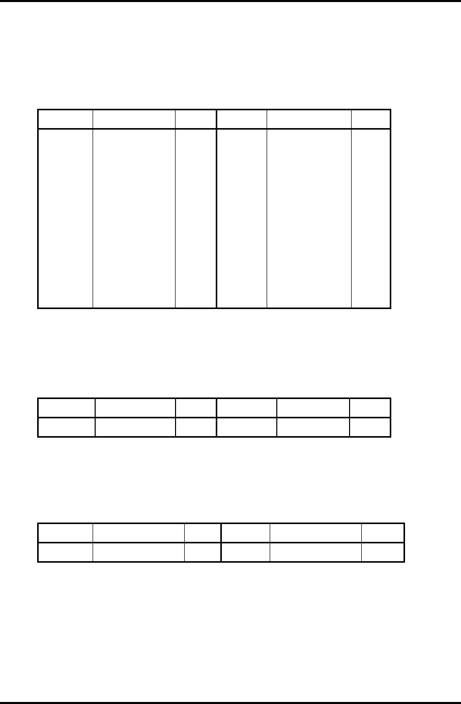
Appendices Appendix C Pin Assignment
C-14 Satellite M30-35 Maintenance Manual (960-455)
C.14 PJ5621 CRT I/F connector (20-pin)
Table C-14 CRT I/F connector (20-pin)
Pin No. Signal name I/O Pin No. Signal name I/O
1 GND - 2 TVLOUT-PXP O
3 GND - 4 TVCOUT-PXP O
5 GND - 6 N.C -
7 DDC-P5V - 8 NVDSCL-P5P I/O
9 (AVSYNC-P3P) I 10 (AHSYNC-P3P) O
11 NVDSDA-P5P I/O 12 GND -
13 GND - 14 CRTBLU-PXP O
15 VGAGND O 16 CRTGRN-PXP -
17 GND - 18 CRTRED-PXP O
19 GND - 20 GND -
C.15 PJ6001 Internal Microphone connector (2-pin)
Table C- 15 Internal Microphone connector (2-pin)
Pin No. Signal name I/O Pin No. Signal name I/O
1 (MICIN-PXP) I 2 A-GND -
C.16 PJ6004 Speaker Connector (left) (2-pin)
Table C- 16 Speaker Connector (left) connector (2-pin)
Pin No. Signal name I/O Pin No. Signal Name I/O
1 SPKOTL-EXN O 2 SPKOTL-EXP O
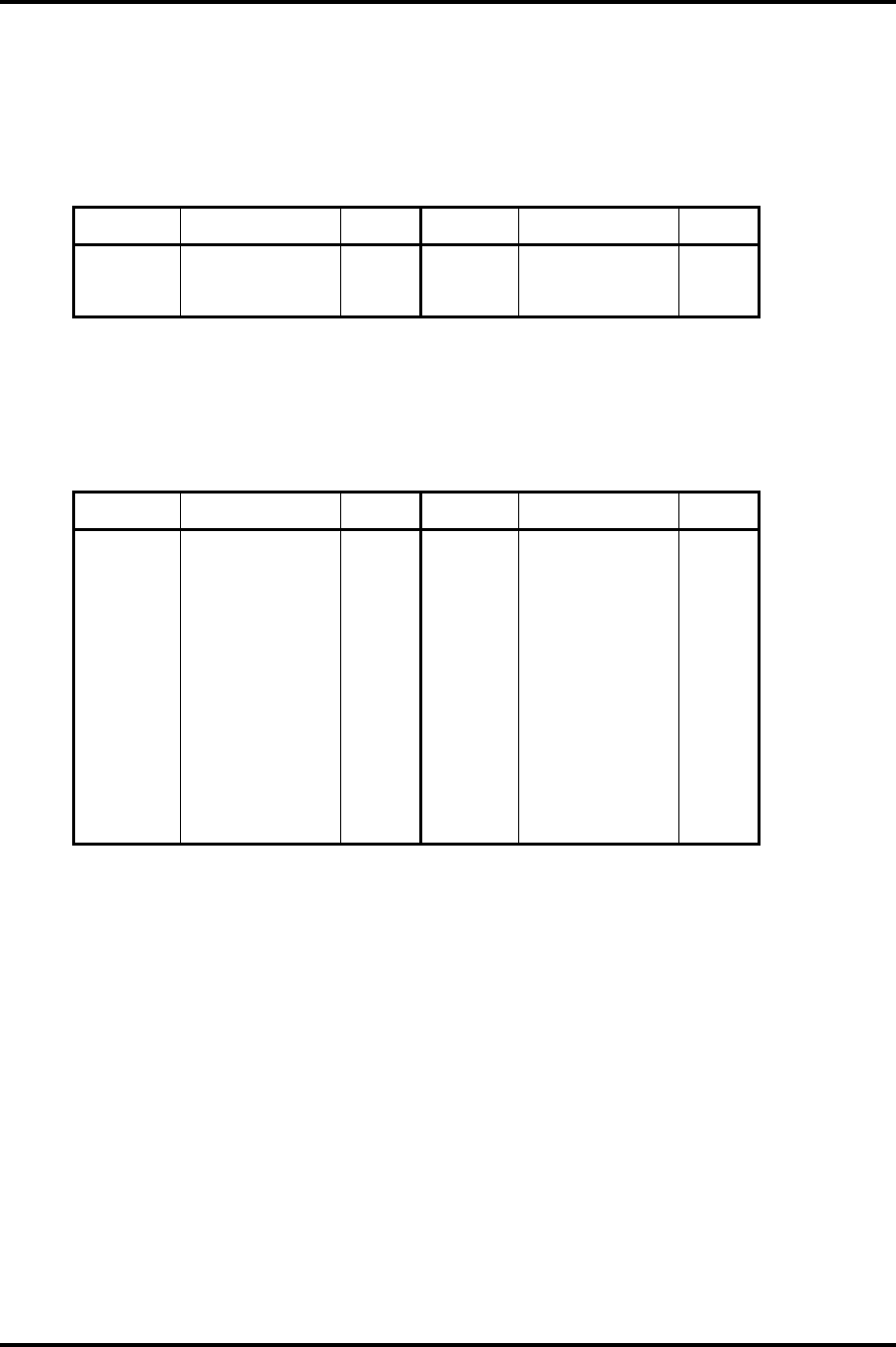
Appendix C Pin Assignment Appendices
Satellite M30-35 Maintenance Manual (960-455) C-15
C.17 PJ6003 Speaker Connector (right) (3-pin)
Table C-17 Speaker connector (right) pin assignment (3-pin)
Pin No. Signal name I/O Pin No. Signal name I/O
1 SPKOTR-EXN O 2 N.C -
3 SPKOTR-EXP O
C.18 PJ7000 CD key I/F connector (18-pin)
Table C-18 CD key I/F connector (18-pin)
Pin No. Signal name I/O Pin No. Signal name I/O
1 M5V - 2 MP3MOD-E5N O
3 CDMODE-E5N O 4 MODBTN-S3N I
5 CDPREV-S5N I 6 CDNEXT-S5N I
7 CDPLAY-S5N I 8 CDSTOP-S5N I
9 GND - 10 BAT102-M5N O
11 BAT1B2-M5N O 12 M5V -
13 PWLE02-M5N O 14 PWLEB2-M5N O
15 M5V - 16 DCINO2-M5N O
17 DCINB2-M5N O 18 M5V -
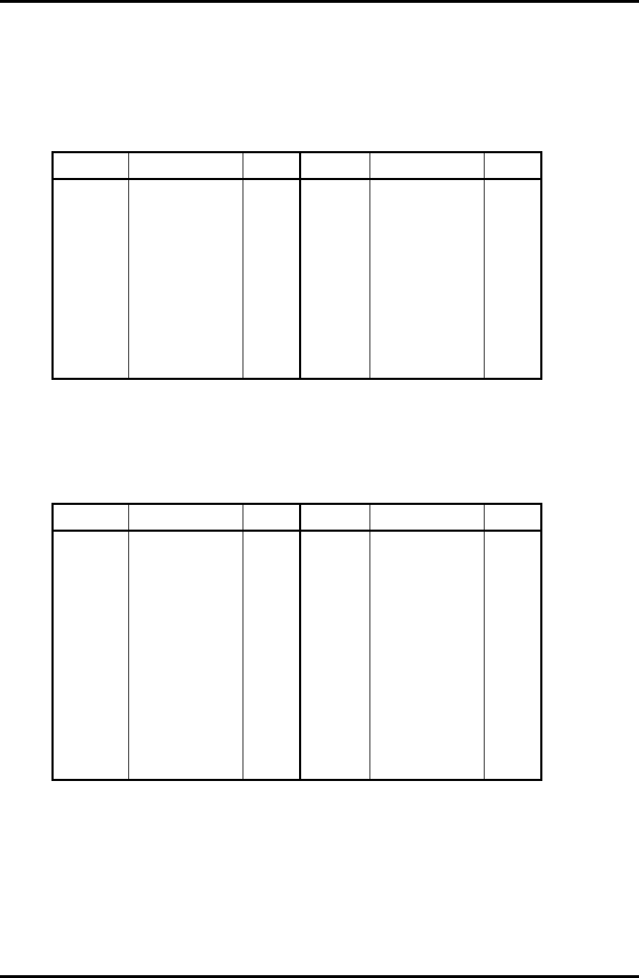
Appendices Appendix C Pin Assignment
C-16 Satellite M30-35 Maintenance Manual (960-455)
C.19 PJ7001 Power switch I/F connector (15-pin)
Table C-19 Power switch I/F connector (15-pin)
Pin No. Signal name I/O Pin No. Signal name I/O
1 PWLEB3-M5N O 2 M5V -
3 BTLED2-P5N O 4 P5V -
5 ODLED2-M5N O 6 M5V -
7 GND - 8 TVOBTN-S3N I
9 ITCBTN-S3N I 10 INETBTN-S3N I
11 PWRSW-S3N I 12 SDLED2-P5N O
13 P5V - 14 HDLED2-P5N O
15 P5V -
C.20 PJ7002 Sound connector PCB I/F connector (20-pin)
Table C-20 Sound connector PCB I/F connector (20-pin)
Pin No. Signal name I/O Pin No. Signal name I/O
1 A-GND - 2 HPL-EXP I/O
3 A-GND - 4 HPR-EXP I/O
5 HPIN-E4N I 6 A-GND -
7 MVREF2-P2V - 8 MIC-PXP I
9 A-GND - 10 MVREF1-P2V I
11 MICIN-P4N I 12 A-GND -
13 GND - 14 USBP1C-S3N O
15 USBP1C-S3P O 16 GND -
17 USBPOC-S3N O 18 USBPOC-S3P O
19 USBOPS-E5V O 20 USBOPS-E5V O
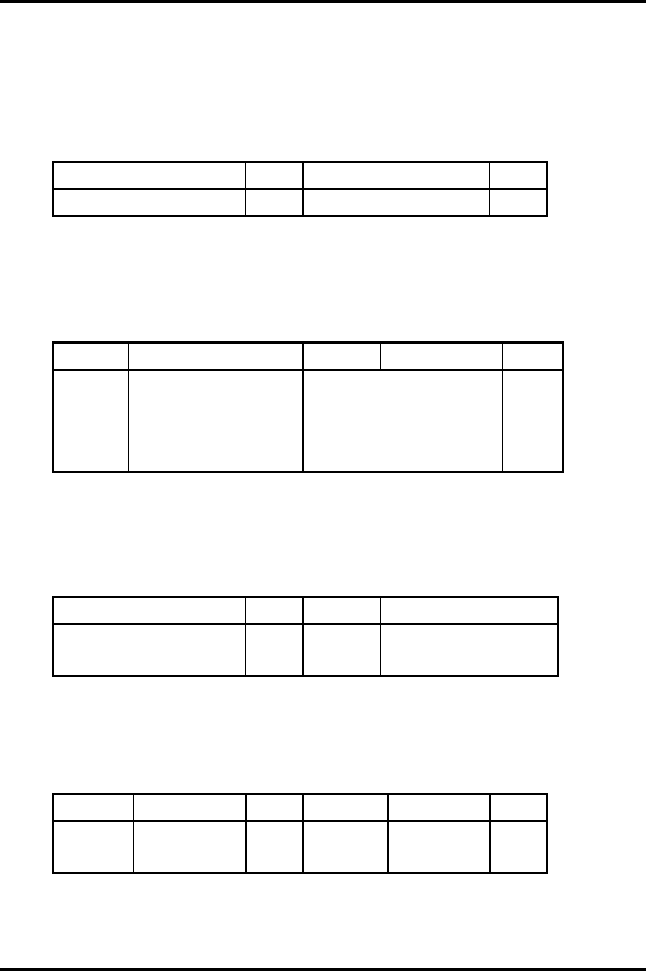
Appendix C Pin Assignment Appendices
Satellite M30-35 Maintenance Manual (960-455) C-17
C.21 PJ7004 Panel switch I/F connector (2-pin)
Table C-21 USB connector PCB I/F connector (2-pin)
Pin No. Signal name I/O Pin No. Signal name I/O
1 PNLOFF-S3V I 2 GND -
C.22 PJ8810 1st Battery connector (7-pin)
Table C-22 1st Battery connector (7-pin)
Pin No. Signal name I/O Pin No. Signal name I/O
1 BTMP1 O 2 (DCHG) -
3 (M5V) - 4 PSCL-S5P I/O
5 PSDA-S5P I/O 6 GND -
7 DBT10V-S5N O
C.23 PJ8490 RTC Battery Connector (3-pin)
Table C-23 RTC Battery connector pin assignment (3-pin)
Pin No. Signal name I/O Pin No. Signal Name I/O
1 (R3V) - 2 N.C -
3 GND -
C.24 PJ8770 FAN connector (3-pin)
Table C-24 FAN connector (3-pin)
Pin No. Signal name I/O Pin No. Signal name I/O
1 FAN VCC - 2 GND -
3 FANG-P3P I

Appendices Appendix C Pin Assignment
C-18 Satellite M30-35 Maintenance Manual (960-455)
C.25 PJ2000 Debugging port (4-pin)
Table C-25 Debugging port (4-pin)
Pin No. Signal name I/O Pin No. Signal name I/O
1 P3V - 2 DBGRX-P3P I
3 DBGTX-P3P O 4 GND -
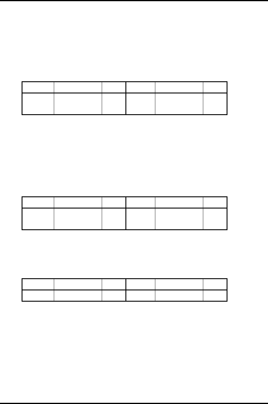
Appendix C Pin Assignment Appendices
Satellite M30-35 Maintenance Manual (960-455) C-19
(only for FMSSY* 32M)
C.26 PJ7003 USB connector PCB I/F connector (4-pin)
Table C-26 USB connector PCB I/F connector (4-pin)
Pin No. Signal name I/O Pin No. Signal name I/O
1 USB1PS-E5V O 2 USBP2C-S3N O
3 USBP2C-S3P O 4 GND -
(only for FMSMP* 64M)
C.27 PJ7003 USB connector PCB I/F connector 1 (4-pin)
Table C-27 USB connector PCB I/F connector 1 (4-pin)
Pin No. Signal name I/O Pin No. Signal name I/O
1 USB1PS-E5V O 2 N.C -
3 N.C - 4 GND -
C.28 PJ7005 USB connector PCB I/F connector 2 (2-pin)
Table C-28 USB connector PCB I/F connector 2 (2-pin)
Pin No. Signal name I/O Pin No. Signal name I/O
1 USBP2C-S3N I 2 USBP2C-S3P I

Appendices Appendix C Pin Assignment
C-20 Satellite M30-35 Maintenance Manual (960-455)
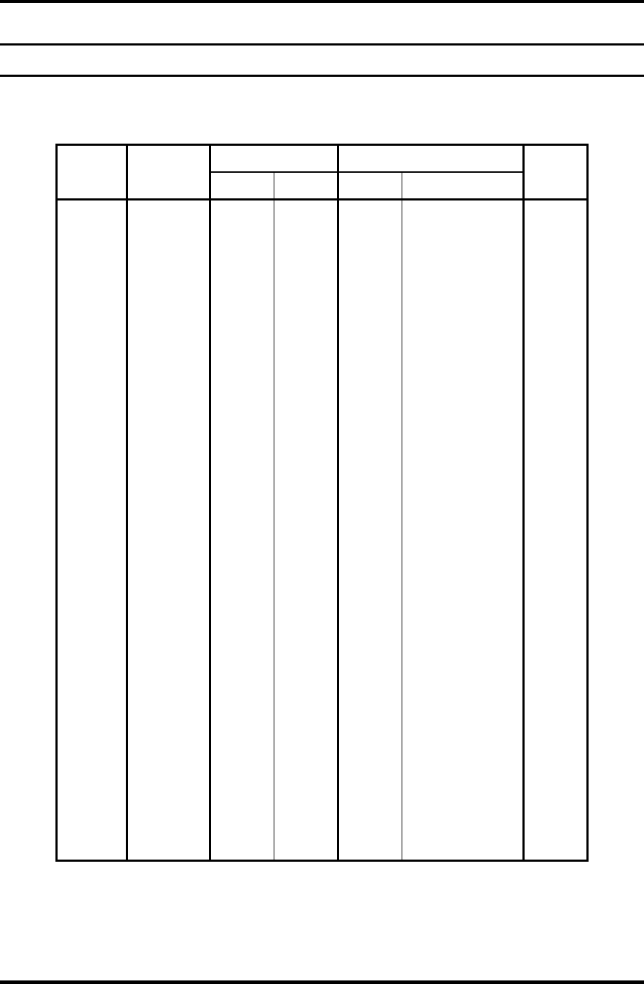
Appendix D Keyboard Scan/Character Codes Appendices
Satellite M30-35 Maintenance Manual (960-455) D-1
Appendix D
Appendix D Keyboard Scan/Character Codes
Table D-1 Scan codes (set 1 and set 2) (1/4)
Code set 1 Code set 2
Cap
No. Keytop
Make Break Make Break
Note
01 ‘ ~ 29 A9 0E F0 0E
02 1 ! 02 82 16 F0 16
03 2 @ 03 83 1E F0 1E
04 3 # 04 84 26 F0 26
05 4 $ 05 85 25 F0 25
06 5 % 06 86 2E F0 2E
07 6 ^ 07 87 36 F0 36
08 7 & 08 88 3D F0 3D *2
09 8 * 09 89 3E F0 3E *2
10 9 ( 0A 8A 46 F0 46 *2
11 0 ) 0B 8B 45 F0 45
12 - _ 0C 8C 4E F0 4E
13 = + 0D 8D 55 F0 55
15 BkSp 0E 8E 66 F0 66
16 Tab 0F 8F 0D F0 0D
17 Q 10 90 15 F0 15
18 W 11 91 1D F0 1D
19 E 12 92 24 F0 24
20 R 13 93 2D F0 2D
21 T 14 94 2C F0 2C
22 Y 15 95 35 F0 35
23 U 16 96 3C F0 3C *2
24 I 17 97 43 F0 43 *2
25 O 13 98 44 F0 44 *2
26 P 19 99 4D F0 4D *2
27 [ { 1A 9A 54 F0 54
28 ] } 1B 9B 5B F0 5B
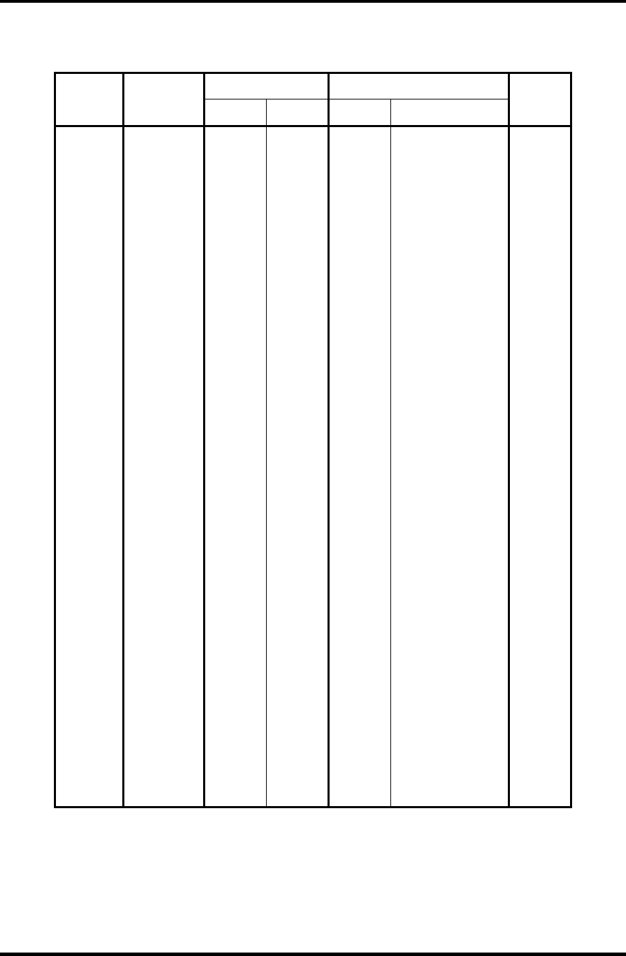
Appendices Appendix D Keyboard Scan/Character Codes
D-2 Satellite M30-35 Maintenance Manual (960-455)
Table D-1 Scan codes (set 1 and set 2) (2/4)
Code set 1 Code set 2
Cap
No. Keytop
Make Break Make Break
Note
29 \ | 2B AB 5D F0 5D *5
30 Caps Lock 3A BA 58 F0 58
31 A 1E 9E 1C F0 1C
32 S 1F 9F 1B F0 1B
33 D 20 A0 23 F0 23
34 F 21 A1 2B F0 2B
35 G 22 A2 34 F0 34
36 H 23 A3 33 F0 33
37 J 24 A4 3B F0 3B *2
38 K 25 A5 42 F0 42 *2
39 L 26 A6 4B F0 4B *2
40 ; : 27 A7 4C F0 4C *2
41 ‘ “ 28 A8 52 F0 52
43 Enter 1C 9C 5A F0 5A *3
44 Shift (L) 2A AA 12 F0 12
45 No.102
key
56 D6 61 F0 61
46 Z 2C AC 1A F0 1A
47 X 2D AD 22 F0 22
48 C 2E AE 21 F0 21
49 V 2F AF 2A F0 2A
50 B 30 B0 32 F0 32
51 N 31 B1 31 F0 31
52 M 32 B2 3A F0 3A *2
53 , < 33 B3 41 F0 41 *2
54 . > 34 B4 49 F0 49 *2
55 / ? 35 B5 4A F0 4A *2
57 Shift (R) 36 B6 59 F0 59
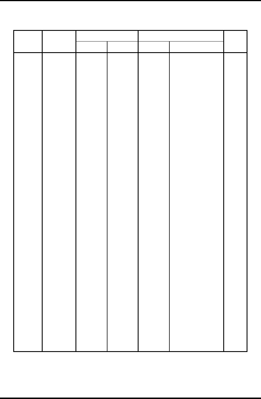
Appendices Appendix D Keyboard Scan/Character Codes
Satellite M30-35 Maintenance Manual (960-455) D-3
Table D-1 Scan codes (set 1 and set 2) (3/4)
Code set 1 Code set 2
Cap
No. Keytop
Make Break Make Break
Note
58 Ctrl 1D 9D 14 F0 14 *3
60 Alt (L) 38 B8 11 F0 11 *3
61 Space 39 B9 29 F0 29
62 ALT (R) E0 38 E0 B8 E0 11 E0 F0 11
75 Ins E0 52 E0 D2 E0 70 E0 F0 70 *1
76 Del E0 53 E0 D3 E0 71 E0 F0 71 *1
79 ← E0 4B E0 CB E0 6B E0 F0 6B *1
80 Home E0 47 E0 C7 E0 6C E0 F0 6C *1
81 End E0 4F E0 CF E0 69 E0 F0 69 *1
83 ↑ E0 48 E0 C8 E0 75 E0 F0 75 *1
84 ↓ E0 50 E0 D0 E0 72 E0 F0 72 *1
85 PgUp E0 49 E0 C9 E0 7D E0 F0 7D *1
86 PgDn E0 51 E0 D1 E0 7A E0 F0 7A *1
89 → E0 4D E0 CD E0 74 E0 F0 74 *1
110 Esc 01 81 76 F0 76
112 F1 3B BB 05 F0 05
113 F2 3C BC 06 F0 06
114 F3 3D BD 04 F0 04
115 F4 3E BE 0C F0 0C
116 F5 3F BF 03 F0 03
117 F6 40 C0 0B F0 0B
118 F7 41 C1 83 F0 83
119 F8 42 C2 0A F0 0A
120 F9 43 C3 01 F0 01
121 F10 44 C4 09 F0 09 *3
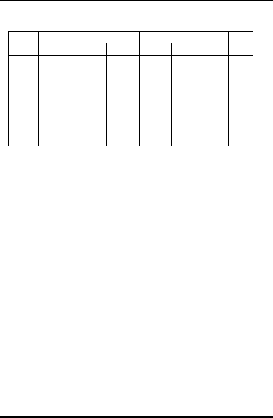
Appendices Appendix D Keyboard Scan/Character Codes
D-4 Satellite M30-35 Maintenance Manual (960-455)
Table D-1 Scan codes (set 1 and set 2) (4/4)
Code set 1 Code set 2 Cap
No. Keytop
Make Break Make Break
Note
122 F11 57 D7 78 F0 78 *3
123 F12 58 D8 07 F0 07 *3
124 PrintSc *6 *6 *6 *6 *6
126 Pause *7 *7 *7 *7 *7
202 Fn — — — — *4
203 Win E0 5B E0 DB E0 1F E0 F0 1F
204 App E0 5D E0 DD E0 2F E0 F0 2F
Notes:
1. * Scan codes differ by mode.
2. * Scan codes differ by overlay function.
3. * Combined with the Fn key makes different codes.
4. * Fn key does not generate a code by itself.
5. * This key corresponds to key No. 42 in a 102-key model.
6. * Refer to Table D-6, No. 124 key scan code.
7. * Refer to Table D-7, No. 126 key scan code.
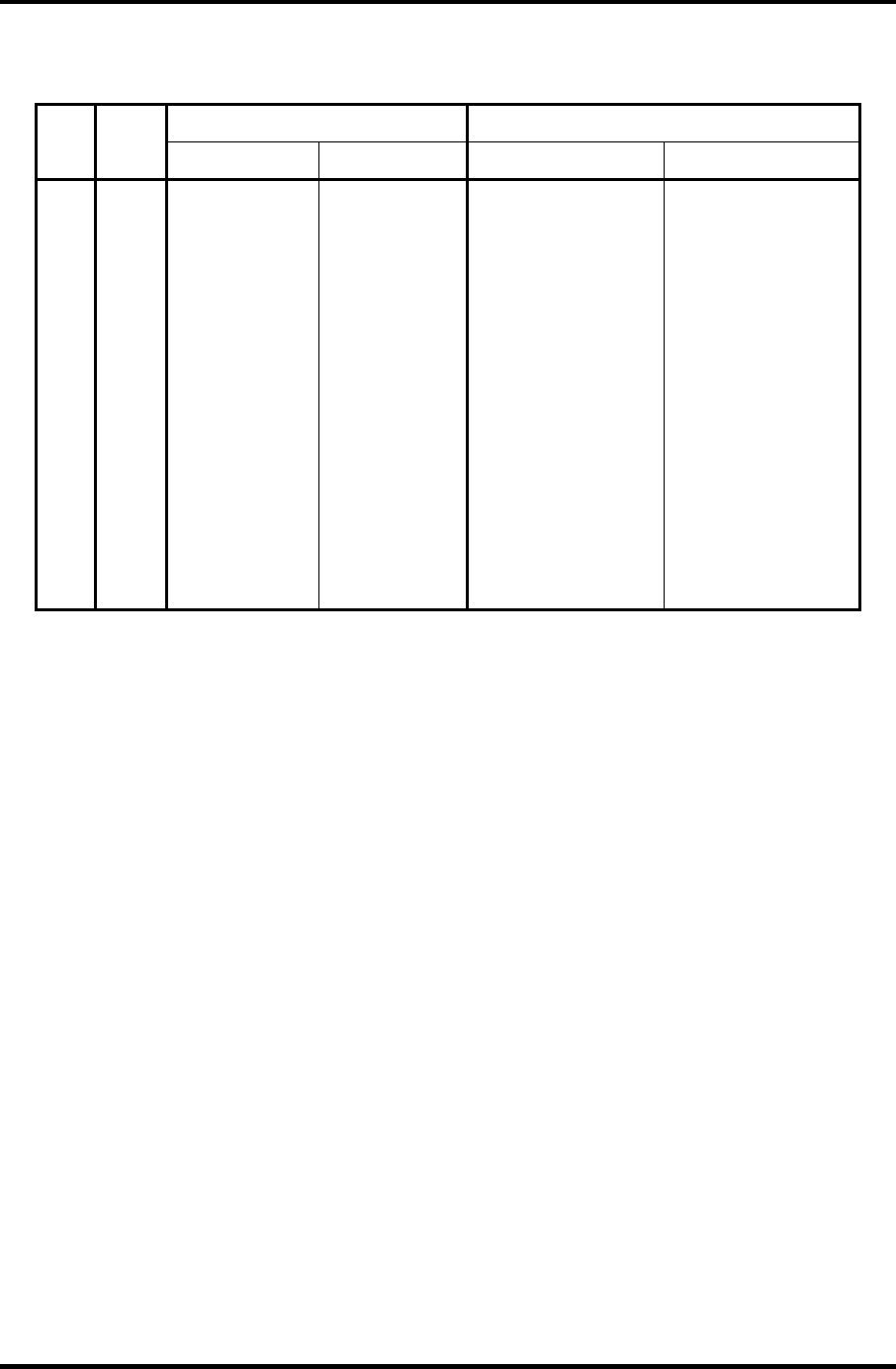
Appendices Appendix D Keyboard Scan/Character Codes
Satellite M30-35 Maintenance Manual (960-455) D-5
Table D-2 Scan codes with left Shift key
Code set 1 Code set 2 Cap
No.
Key
top Make Break Make Break
55 / E0 AA E0 35 E0 B5 E0 2A E0 F0 12 E0 4A E0 F0 4A E0 12
75 INS E0 AA E0 52 E0 D2 E0 2A E0 F0 12 E0 70 E0 F0 70 E0 12
76 DEL E0 AA E0 53 E0 D3 E0 2A E0 F0 12 E0 71 E0 F0 71 E0 12
79 ← E0 AA E0 4B E0 CB E0 2A E0 F0 12 E0 6B E0 F0 6B E0 12
80 Home E0 AA E0 47 E0 C7 E0 2A E0 F0 12 E0 6C E0 F0 6C E0 12
81 End E0 AA E0 4F E0 CF E0 2A E0 F0 12 E0 69 E0 F0 69 E0 12
83 ↑ E0 AA E0 48 E0 C8 E0 2A E0 F0 12 E0 75 E0 F0 75 E0 12
84 ↓ E0 AA E0 50 E0 D0 E0 2A E0 F0 12 E0 72 E0 F0 72 E0 12
85 PgUp E0 AA E0 49 E0 C9 E0 2A E0 F0 12 E0 7D E0 F0 7D E0 12
86 PgDn E0 AA E0 51 E0 D1 E0 2A E0 F0 12 E0 7A E0 F0 7A E0 12
89 → E0 AA E0 4D E0 CD E0 2A E0 F0 12 E0 74 E0 F0 74 E0 12
203 Win E0 AA E0 5B E0 DB E0 2A E0 F0 12 E0 1F E0 F0 1F E0 12
204 App E0 AA E0 5D E0 DD E0 2A E0 F0 12 E0 2F E0 F0 2F E0 12
Note : The table above shows scan codes with the left Shift key. In combination with
the right Shift key, scan codes are changed as listed below:
With left Shift With right Shift
Set 1 E0 AA ___________E0 B6
E0 2A ____________E0 36
Set 2 E0 F0 12 _________E0 F0 59
E0 12 ____________E0 59
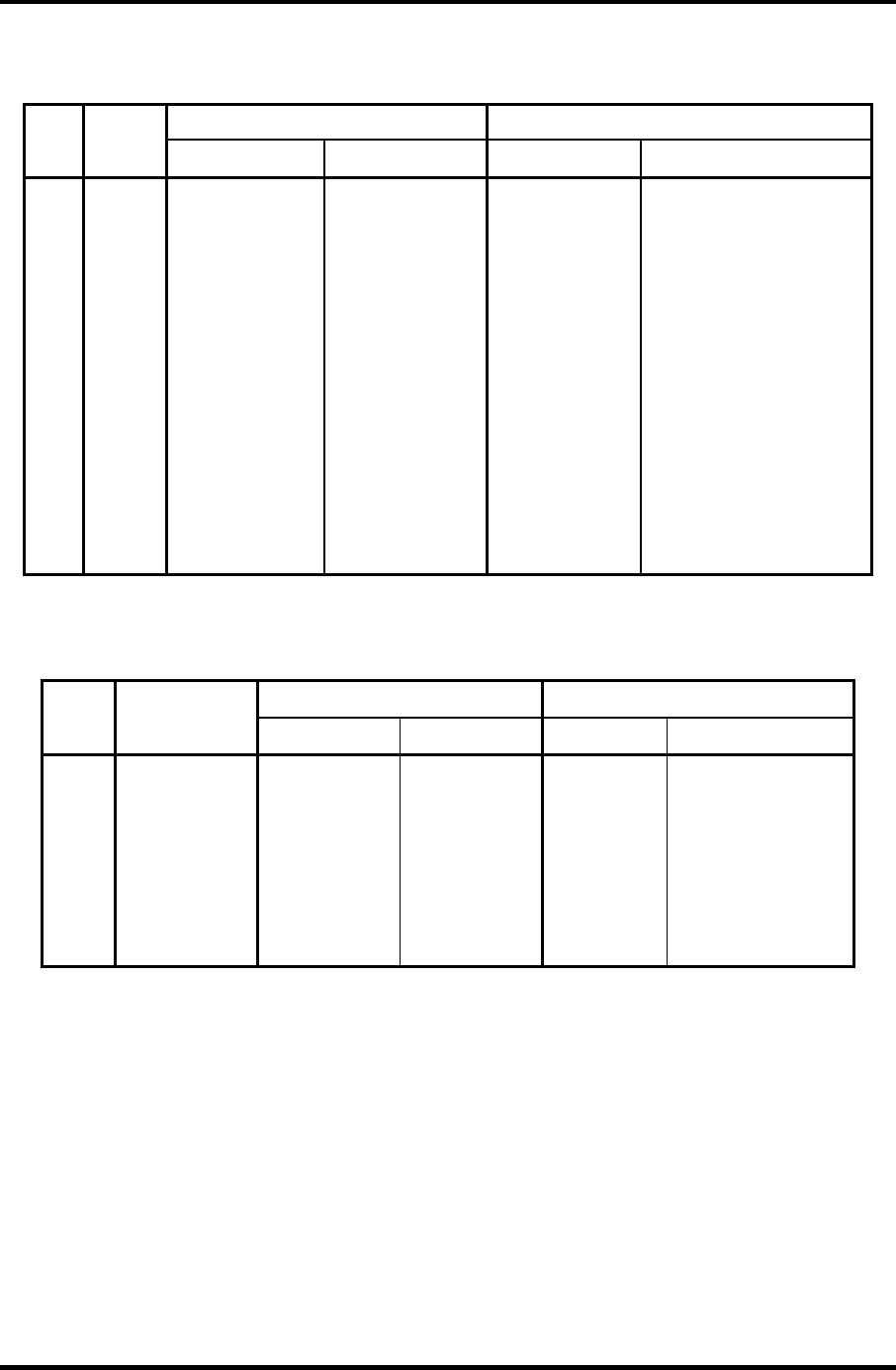
Appendices Appendix D Keyboard Scan/Character Codes
D-6 Satellite M30-35 Maintenance Manual (960-455)
Table D-3 Scan codes in Numlock mode
Code set 1 Code set 2 Cap
No.
Key
top Make Break Make Break
75 INS E0 2A E0 52 E0 D2 E0 AA E0 12 E0 70 E0 F0 70 E0 F0 12
76 DEL E0 2A E0 53 E0 D3 E0 AA E0 12 E0 71 E0 F0 71 E0 F0 12
79 ← E0 2A E0 4B E0 CB E0 AA E0 12 E0 6B E0 F0 6B E0 F0 12
80 Home E0 2A E0 47 E0 C7 E0 AA E0 12 E0 6C E0 F0 6C E0 F0 12
81 End E0 2A E0 4F E0 CF E0 AA E0 12 E0 69 E0 F0 69 E0 F0 12
83 ↑ E0 2A E0 48 E0 C8 E0 AA E0 12 E0 75 E0 F0 75 E0 F0 12
84 ↓ E0 2A E0 50 E0 D0 E0 AA E0 12 E0 72 E0 F0 72 E0 F0 12
85 PgUp E0 2A E0 49 E0 C9 E0 AA E0 12 E0 7D E0 F0 7D E0 F0 12
86 PgDn E0 2A E0 51 E0 D1 E0 AA E0 12 E0 7A E0 F0 7A E0 F0 12
89 → E0 2A E0 4D E0 CD E0 AA E0 12 E0 74 E0 F0 74 E0 F0 12
203 Win E0 2A E0 5B E0 DB E0 AA E0 12 E0 1F E0 F0 1F E0 F0 12
204 App E0 2A E0 5D E0 DD E0 AA E0 12 E0 2F E0 F0 2F E0 F0 12
Table D-4 Scan codes with Fn key
Code set 1 Code set 2 Cap
No.
Keytop Make Break Make Break
43 ENT E0 1C E0 9C E0 5A E0 F0 5A
58 CTRL E0 1D E0 9D E0 14 E0 F0 14
60 LALT E0 38 E0 B8 E0 11 E0 F0 11
121 ARROW 45 C5 77 F0 77
122 NUMERIC 45 C5 77 F0 77
123 Scrl 46 C5 7E F0 7E
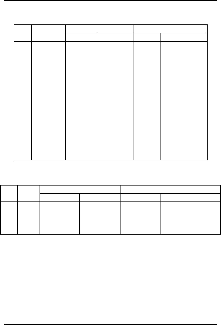
Appendices Appendix D Keyboard Scan/Character Codes
Satellite M30-35 Maintenance Manual (960-455) D-7
Table D-5 Scan codes in overlay mode
Code set 1 Code set 2
Cap
No. Keytop
Make Break Make Break
09 8 (8) 48 C8 75 F0 75
10 9 (9) 49 C9 7D F0 7D
11 0 (*) 37 B7 7C F0 7C
23 U (4) 4B CB 6B F0 6B
24 I (5) 4C CC 73 F0 73
25 O (6) 4D CD 74 F0 74
26 P (–) 4A CA 7B F0 7B
37 J (1) 4F CF 69 F0 69
38 K (2) 50 D0 72 F0 72
39 L (3) 51 D1 7A F0 7A
40 ; (+) 4E CE 79 F0 79
52 M (0) 52 D2 70 F0 70
54 . (.) 53 D3 71 F0 71
55 / (/) E0 35 E0 B5 40 4A E0 F0 4A
Table D-6 No.124 key scan code
Code set 1 Code set 2 Key
top Shift
Make Break Make Break
Prt Sc Common E0 2A E0 37 E0 B7 E0 AA E0 12 E0 7C E0 F0 7C E0 F0 12
Ctrl + E0 37 E0 B7 E0 7C E0 F0 7C
Shift + E0 37 E0 B7 E0 7C E0 F0 7C
Alt + 54 D4 84 F0 B4

Appendices Appendix D Keyboard Scan/Character Codes
D-8 Satellite M30-35 Maintenance Manual (960-455)
Table D-7 No.126 key scan code
Code set 1 Code set 2 Key
top
Shift
Make Make
Pause Common
*
E1 1D 45 E1 9D C5 E1 14 77 E1 F0 14 F0 77
Ctrl* E0 46 E0 C6 E0 7E E0 F0 7E
*: This key generates only make codes.
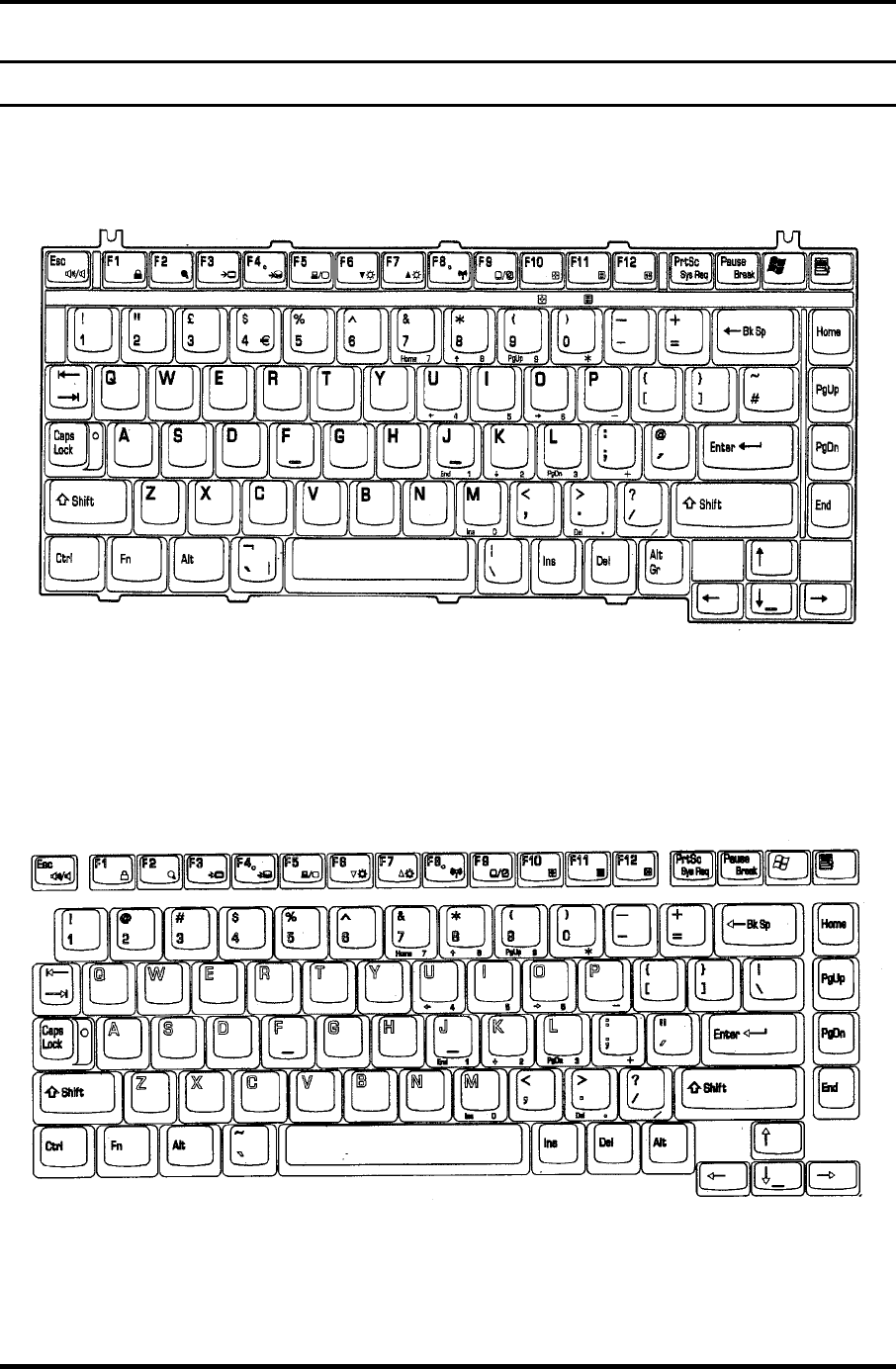
Appendix E Key Layout Appendices
Appendix E
Appendix E Key Layout
E.1 United Kingdom (UK) Keyboard
Figure E-1 UK keyboard
E.2 United States (US) Keyboard
Figure E-2 US keyboard
Satellite M30-35 Maintenance Manual (960-455) E-1

Appendices Appendix E Key Layout
E-2 Satellite M30-35 Maintenance Manual (960-455)
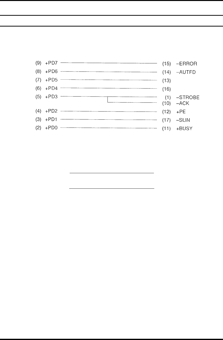
Appendix F Wiring Diagrams Appendices
Appendix F
Appendix F Wiring Diagrams
F.1 Parallel Port Wraparound Connector
-SELECT
-PINT
Figure F-1 Parallel port wraparound connector
F.2 LAN Loopback Connector
(
1
)
BIBAP
(
TX+
)
(
2
)
BIDAN
(
TX-
)
(3) BIDBP (RX+)
(6) BIDBN (RX-)
Figure F-2 LAN loopback Connector
Satellite M30-35 Maintenance Manual (960-455) F-1

Appendices Appendix F Wiring Diagrams
F-2 Satellite M30-35 Maintenance Manual (960-455)
Appendix G BIOS Rewrite Procedures Appendices
Appendix G
Appendix G BIOS Rewrite Procedures
This Appendix explains how to rewrite the system BIOS program when you update the
system BIOS.
Tools
To rewrite the BIOS, you need the following tool:
BIOS/EC/KBC rewriting disk for the computer that has renewed BIOS data.
Rewriting the BIOS
1. Set the system to boot mode.
2. Turn off the power to the computer.
3. Remove the external cable and PC card.
4. Connect an external FDD and insert the BIOS/EC/KBC rewriting disk into either the
external FDD.
5. Turn on the power while holding down the No. 01 key.
For example
(US Keyboard)
(UK Keyboard)
(Keep holding down the key until a message appears on the screen.)
The BIOS rewriting starts.
6. When the process is completed, eject the BIOS/EC/KBC rewriting disk and the
system is automatically reset.
Satellite M30-35 Maintenance Manual (960-455) G-1

Appendices Appendix G BIOS Rewrite Procedures
G-2 Satellite M30-35 Maintenance Manual (960-455)

Appendix I Reliability Appendices
Appendix I
Appendix I Reliability
The following table shows MTBF (Mean Time between Failures).
Table I-1 MTBF
MTBF Time (hours)
VRAM32MB (FMSSY* board) model 7323.49
VRAM64MB (FMSMP* board) model 7341.30
Satellite M30-35 Maintenance Manual (960-455) I-1

Appendices Appendix I Reliability
I-2 Satellite M30-35 Maintenance Manual (960-455)

Appendix J SETUP Appendices
Appendix J
Appendix J SETUP
This function displays the current system setup information. The options are listed blow.
1. Main
(1) Total Memory
(2) System Date
(3) System Time
(4) BIOS Ver.
2. Advanced
(1) Power On Display
(2) LCD Display Stretch
(3) TV Type
(4) Dynamic CPU Freq Mode
(5) Built-in LAN
(6) Network Boot Protocol
(7) Wake-up On LAN
(8) Internal Pointing Device
(9) Parallel Port Mode
3. Security
(1) Power on Password
4. Boot
(1) Hard Drive
(2) Removable Devices
(3) CD/DVD-ROM Drive
(4) Network Boot
5. Exit
(1) Exit Saving Changes
(2) Exit Discarding Changes
(3) Load Setup Defaults
(4) Discard Changes
(5) Save Changes
Satellite M30-35 Maintenance Manual (960-455) J-1
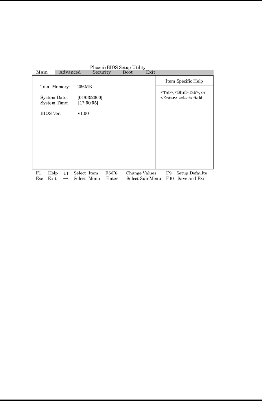
Appendices Appendix J SETUP
To access the SETUP display, power on the computer and while “TOSHIBA” logo is
displayed, press [F2]. Then, the main menu similar to the one blow appears.
There are five tabs (Main, Advanced, Security, Boot and Exit) in the SETUP menu. To move
between the tabs, press ← or →. Each option is displayed on the menu by selecting a tab.
“Item Specific Help” on the right of the menu describes each option.
Figure J-1 Main menu
SETUP Options
The SETUP screen is divided into functionally related groups. This section describes each
group and its options.
Main
1. Total Memory
This option displays the total amount of memory installed and is automatically
calculated by the computer. You cannot change this value.
2. System Date
This option is used to set the date of the computer. To change the value, press [F5] or
[F6] and press [Enter] to select the value.
System Date Sets the date.
3. System Time
This option is used to set the time of the computer. To change the value, press [F5] or
[F6] and press [Enter] to select the value.
System Time Sets the time.
4. BIOS Ver.
This option displays the BIOS version of the computer. You cannot change this value.
J-2 Satellite M30-35 Maintenance Manual (960-455)

Appendix J SETUP Appendices
Advanced
1. Power On Display
[Auto-Selected] If any external display is connected, the power on display will
be in analog RGB only mode. Otherwise it will be in LCD
only mode.
[LCD+Analog RGB] Display both the integrated LCD screen and analog RGB
screen mode.
2. LCD Display Stretch
[Enabled] LCD display stretch is enabled.
[Disabled] LCD display stretch is disabled.
3. TV Type
This option sets the TV type options.
[NTSC (US)] TV in the U.S. system
[NTSC (JAPAN)] TV in Japanese system
[PAL] TV in Europe system
4. Dynamic CPU Freq Mode
[Switchable] CPU frequency is dynamically switchable.
[Always High] CPU frequency is always high.
[Always Low] CPU frequency is always low.
5. Built-in LAN
[Enabled] Built-in LAN is enabled.
[Disabled] Built-in LAN is disabled.
6. Network Boot Protocol
[PXE] Network boot by the PXE protocol.
[RPL] Network boot by the RPL protocol.
7. Wake-up On LAN
[Enabled] Wake-up is enabled from Built-in LAN.
[Disabled] Wake-up is disabled from Built-in LAN.
8. Internal Pointing Device
[Enabled] Internal pointing device is enabled.
[Disabled] Internal pointing device is disabled.
Satellite M30-35 Maintenance Manual (960-455) J-3

Appendices Appendix J SETUP
J-4 Satellite M30-35 Maintenance Manual (960-455)
9. Parallel Port Mode
This option sets the mode for the parallel port using options.
[ECP] Sets the port type to Extended Capabilities Port (ECP). For
most printers, the port should be set to “ECP.” (Default)
[Bi-derectional] This setting should be used with some other parallel devices.
Security
1. Power On Password
To set a new user password, press [Enter] and enter the new password twice.
[Not Registered] The password has not been registered.
[Registered] The password has been registered.
Boot
This option displays boot sequence of devices of the computer.
Hard Drive mainly for HDD
Removable Devices mainly for FDD
CD/DVD-ROM Drives mainly for CD/DVD-ROM
Network Boot mainly for LAN
Exit
1. Exit Saving changes
Exit System Setup and save your changes to CMOS.
2. Exit Discarding Changes
Exit utility without saving Setup changes data to CMOS.
3. Load Setup Defaults
Load default values for all Setup items.
4. Discard Changes
Load previous values from CMOS for all Setup Items.
5. Save Changes
Save Setup data to CMOS.
