Toshiba Vf Fs1 Instruction Manual
2014-12-13
: Toshiba Toshiba-Vf-Fs1-Instruction-Manual-131062 toshiba-vf-fs1-instruction-manual-131062 toshiba pdf
Open the PDF directly: View PDF ![]() .
.
Page Count: 252 [warning: Documents this large are best viewed by clicking the View PDF Link!]
- Cover
- I. Safety precautions
- II. Introduction
- Contents
- 1. Read first
- 2. Connection
- 3. Operations
- 4. Basic VF-FS1 operations
- 5. Basic parameters
- 5.1 Setting acceleration/deceleration time
- 5.2 Specifying an operation mode, using parameters
- 5.3 Selection of operation mode
- 5.4 Meter setting and adjustment
- 5.5 Standard default setting
- 5.6 Forward/reverse run selection (Operation panel operation)
- 5.7 Maximum frequency
- 5.8 Upper limit and lower limit frequencies
- 5.9 Base frequency
- 5.10 Selecting control mode
- 5.11 Manual torque boost - increasing torque boost at low speeds
- 5.12 Setting the electronic thermal
- 5.13 Preset-speed operation (speeds in 7 steps)
- 6. Extended parameters
- 6.1 Input/output parameters
- 6.2 Input signal selection
- 6.3 Terminal function selection
- 6.4 Basic parameters 2
- 6.5 Frequency priority selection
- 6.6 Operation frequency
- 6.7 DC braking
- 6.8 Auto-stop in case of lower-limit frequency continuous operation
- 6.9 Jump frequency - jumping resonant frequencies
- 6.10 Bumpless operation
- 6.11 PWM carrier frequency
- 6.12 Trip-less intensification
- 6.13 Droop control
- 6.14 Conducting PID control
- 6.15 Setting motor constants
- 6.16 Acceleration/deceleration time 2
- 6.17 Protection functions
- 6.18 Forced fire-speed control function
- 6.19 Adjustment parameters
- 6.20 Operation panel parameter
- 6.21 Communication function (Common serial)
- 6.22 Parameters for options
- 6.23 Permanent magnetic motors
- 7. Applied operation
- 8. Monitoring the operation status
- 9. Measures to satisfy the standards
- 10. Peripheral devices
- 11.Table of parameters and data
- 12. Specifications
- 13. Before making a service call - Trip information and remedies
- 14. Inspection and maintenance
- 15. Warranty
- 16. Disposal of the inverter
- Buck cover
Instruction ManualIndustrial Inverter
TOSVE
R
T VF
-
FS
1
IIII
1
2
3
4
5
6
7
8
9
1010
1111
1212
1313
1414
1515
1616
E6581381
R
ea
d
f
i
r
s
t
I
S
a
f
e
t
y
p
r
eca
u
t
ion
s
I
n
t
r
odu
c
t
ion
C
on
t
e
n
t
s
C
onn
ec
t
ion
O
p
e
r
a
t
ion
s
B
as
i
c
VF
-
FS
1
op
e
r
a
t
ion
s
B
as
i
c
p
a
r
a
m
e
t
e
r
s
E
x
t
e
nd
e
d
p
a
r
a
m
e
t
e
r
s
A
ppli
e
d
op
e
r
a
t
ion
M
oni
t
o
r
ing
t
h
e
op
e
r
a
t
ion
s
t
a
t
u
s
M
eas
u
r
es
t
o
sa
t
i
s
f
y
t
h
e
s
t
a
nd
a
r
d
s
P
e
r
iph
e
r
a
l
d
ev
i
ces
T
a
bl
e
o
f
p
a
r
a
m
e
t
e
r
s
a
nd
d
a
t
a
S
p
ec
i
f
i
ca
t
ion
s
B
e
f
o
r
e
m
ak
ing
a
se
r
v
i
ce
ca
ll
I
n
s
p
ec
t
ion
a
nd
m
a
in
t
e
n
a
n
ce
W
a
rr
a
n
t
y
D
i
s
po
sa
l
o
f
t
h
e
in
ve
r
t
e
r
NOTICE
1. Make sure that this instruction manual is delivered to the
end user of the inverter unit.
2. Read this manual before installing or operating the inverter
unit, and store it in a safe place for reference.
Instruction Manual
TOSVE
R
T
T
M
VF
-
FS
1
3-phase 200V class 0.4 VQ30kW
3-phase 400V class 0.4 VQ30kW
2006 Ver. 100/101
TOS
H
I
BA
I
NDU
ST
R
I
A
L
AND
POWE
R
SYSTE
M
S
&
SE
R
VI
C
ES
C
O
M
P
AN
Y
OVERSEAS SALES & MARKETING DEPT.
ELECTRICAL APPARATUS & MEASUREMENT
DIV.
1-1, Shibaura 1-chome, Minato-Ku,
Tokyo 105-8001, Japan
TEL: +81-(0)3-3457-4911
FAX: +81-(0)3-5444-9268
TOS
H
I
BA
I
N
TE
RNA
TIO
NA
L
C
O
R
PO
RA
TIO
N
13131 West Little York RD., Houston,
TX 77041, U.S.A
TEL: +1-713-466-0277
FAX: +1-713-896-5226
TOS
H
I
BA
A
SI
A
P
AC
IFI
C
PTE., LT
D
152 Beach Rd., #16-00 Gateway East,
Singapore 189721
TEL: +65-6297-0900
FAX: +65-6297-5510
TOS
H
I
BA
CH
I
NA
C
O., LT
D
23rd Floor, HSBC Tower, 101 Yin Cheng
East Road, Pudong New Area, Shanghai
200120, The People's Republic of China
TEL: +86-(0)21-6841-5666
TOS
H
I
BA
I
N
TE
RNA
TIO
NA
L
C
O
R
PO
RA
TIO
N
PTY.,
LT
D
2 Morton Street Parramatta, NSW2150, Australia
TEL: +61-(0)2-9768-6600
FAX: +61-(0)2-9890-7542
TOS
H
I
BA
I
N
FO
R
M
A
TIO
N
, I
NDU
ST
R
I
A
L
AND
POWE
R
SYSTE
M
S T
A
IW
AN
C
O
R
P.
6F, No66, Sec1 Shin Sheng N.RD, Taipei, Taiwan
TEL: +886-(0)2-2581-3639
FAX: +886-(0)2-2581-3631
For further information, please contact your nearest Toshiba Liaison Representative or International Operations - Producer Goods.
The data given in this manual are subject to change without notice.
2006-01
Industrial Inverter
For 3-phase induction motors
E6581381
1
I
I. Safety precautions
The items described in these instructions and on the inverter itself are very important so that you can use the
inverter safely, prevent injury to yourself and other people around you as well as to prevent damage to property in
the area. Thoroughly familiarize yourself with the symbols and indications shown below and then continue to read
the manual. Make sure that you observe all warnings given.
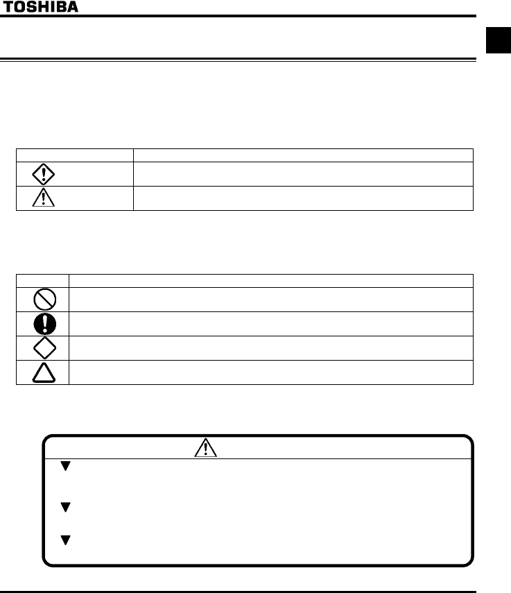
Explanation of markings
Marking Meaning of marking
Danger Indicates that errors in operation may lead to death or serious injury.
Warning Indicates that errors in operation may lead to injury (*1) to people or that these errors may
cause damage to physical property. (*2)
(*1) Such things as injury, burns or shock that will not require hospitalization or long periods of outpatient
treatment.
(*2) Physical property damage refers to wide-ranging damage to assets and materials.
Meanings of symbols
Marking Meaning of marking
Indicates prohibition (Don't do it).
What is prohibited will be described in or near the symbol in either text or picture form.
Indicates something mandatory (must be done).
What is mandatory will be described in or near the symbol in either text or picture form.
Indicates danger.
What is dangerous will be described in or near the symbol in either text or picture form.
Indicates warning.
What the warning should be applied to will be described in or near the symbol in either text or picture form.
■Limits in purpose
This inverter is used for controlling speeds of three-phase induction motors in general industrial use.
Safety precautions
The inverter cannot be used in any device that would present danger to the human body or from which
malfunction or error in operation would present a direct threat to human life (nuclear power control
device, aviation and space flight control device, traffic device, life support or operation system, safety
device, etc.). If the inverter is to be used for any special purpose, first get in touch with the supplier.
This product was manufactured under the strictest quality controls but if it is to be used in critical
equipment, for example, equipment in which errors in malfunctioning signal output system would cause
a major accident, safety devices must be installed on the equipment.
Do not use the inverter for loads other than those of properly applied three-phase induction motors in
general industrial use. (Use in other than properly applied three-phase induction motors may cause an
accident.)
E6581381
2
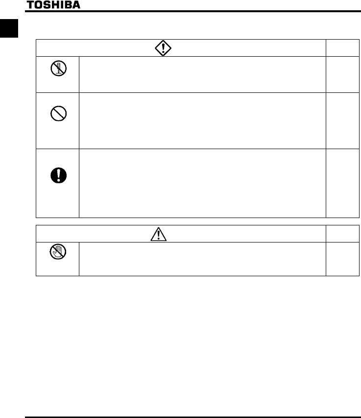
I■General Operation
Danger See item
Disassembly
prohibited
•Never disassemble, modify or repair.
This can result in electric shock, fire and injury. For repairs, call your sales distributor.
2.
Prohibited
•Never remove the front cover when power is on or open door if enclosed in a cabinet.
The unit contains many high voltage parts and contact with them will result in electric shock.
•Don't stick your fingers into openings such as cable wiring hole and cooling fan covers.
This can result in electric shock or other injury.
•Don't place or insert any kind of object into the inverter (electrical wire cuttings, rods, wires etc.).
This can result in electric shock or fire.
•Do not allow water or any other fluid to come in contact with the inverter.
This can result in electric shock or fire.
2.1
2.
2.
2.
Mandatory
•Turn power on only after attaching the front cover or closing door if enclosed in a cabinet.
If power is turned on without the front cover attached or closing door if enclosed in a
cabinet, this can result in electric shock or other injury.
•If the inverter begins to emit smoke or an unusual odor, or unusual sounds, immediately
turn power off.
If the equipment is continued in operation in such a state, the result may be fire. Call your
local sales agency for repairs.
•Always turn power off if the inverter is not used for long periods of time since there is a
possibility of malfunction caused by leaks, dust and other material. If power is left on with
the inverter in that state, it may result in fire.
2.1
3.
3.
Warning See item
Prohibited
contact
•Do not touch heat radiating fins or discharge resistors.
These device are hot, and you'll get burned if you touch them.
3.
E6581381
3
I
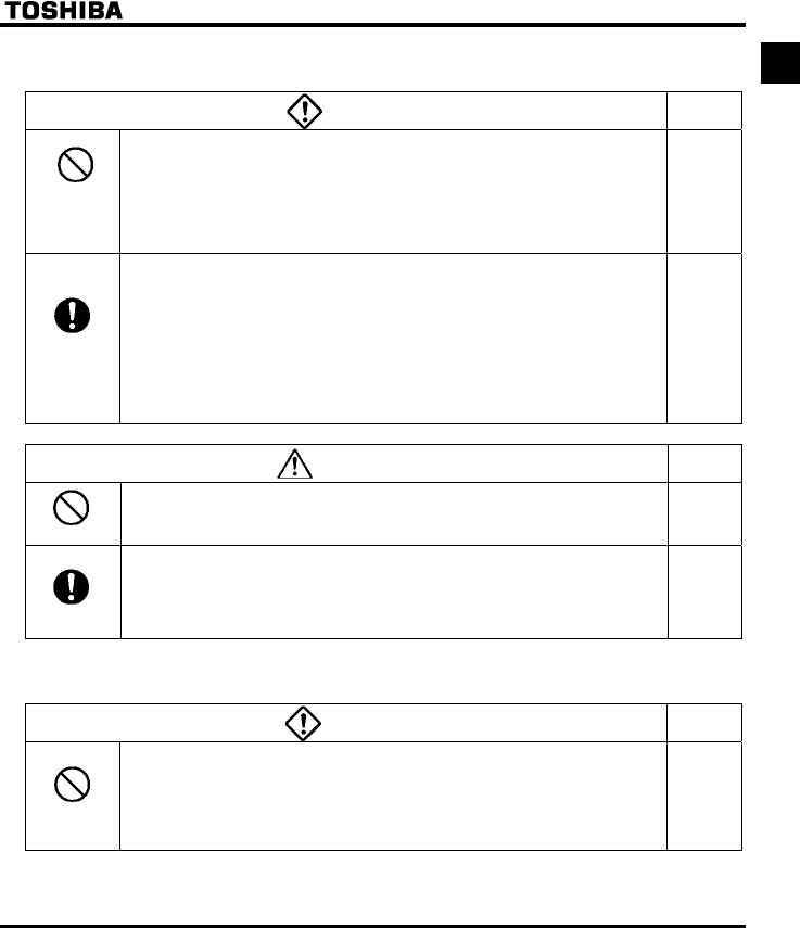
■Transportation & installation
Danger See item
Prohibited
•Do not install or operate the inverter if it is damaged or any component is missing.
This can result in electric shock or fire. Please consult your local sales agency for repairs.
Call your local sales agency for repairs.
•Do not place any inflammable objects nearby.
If a flame is emitted due to malfunction, it may result in a fire.
•Do not install in any location where the inverter could come into contact with water or
other fluids.
This can result in electric shock or fire.
1.4.4
1.4.4
2.
Mandatory
•Must be used in the environmental conditions prescribed in the instruction manual.
Use under any other conditions may result in malfunction.
•Mount the inverter on a metal plate.
The rear panel gets very hot. Do not install in an inflammable object, this can result in fire.
•Do not operate with the front panel cover removed. This can result in electric shock.
Failure to do so can lead to risk of electric shock and can result in death or serious injury.
•An emergency stop device must be installed that fits with system specifications (e.g. shut
off input power then engage mechanical brake). Operation cannot be stopped immediately
by the inverter alone, thus risking an accident or injury.
•All options used must be those specified by Toshiba.
The use of any other option may result in an accident.
1.4.4
1.4.4
1.4.4
1.4.4
1.4.4
Warning See item
Prohibited
•When transporting or carrying, do not hold by the front panel covers.
The covers may come off and the unit will drop out resulting in injury.
•Do not install in any area where the unit would be subject to large amounts of vibration.
That could result in the unit falling, resulting in injury.
2.
1.4.4
Mandatory
•The main unit must be installed on a base that can bear the unit's weight.
If the unit is installed on a base that cannot withstand that weight, the unit may fall
resulting in injury.
•If braking is necessary (to hold motor shaft), install a mechanical brake.
The brake on the inverter will not function as a mechanical hold, and if used for that
purpose, injury may result.
1.4.4
1.4.4
■Wiring
Danger See item
Prohibited
•Do not connect input power to the output (motor side) terminals (U/T1,V/T2,W/T3).
That will destroy the inverter and may result in fire.
•Do not connect resistors to the DC terminals (between PA/+ and PC/-).
That may cause a fire.
•Within ten minutes after turning off input power, do not touch wires of devices (MCCB)
connected to the input side of the inverter.
That could result in electric shock.
2.2
2.2
2.2
E6581381
4
I Danger See item
Mandatory
•Electrical installation work must be done by a qualified expert.
Connection of input power by someone who does not have that expert knowledge may
result in fire or electric shock.
•Connect output terminals (motor side) correctly.
If the phase sequence is incorrect, the motor will operate in reverse and that may result in
injury.
•Wiring must be done after installation.
If wiring is done prior to installation that may result in injury or electric shock
•The following steps must be performed before wiring.
(1) Turn off all input power.
(2) Wait at least ten minutes and check to make sure that the charge lamp is no longer lit.
(3) Use a tester that can measure DC voltage (800VDC or more), and check to make sure
that the voltage to the DC main circuits (across PA/+ and PC/-) is 45V or less.
If these steps are not properly performed, the wiring will cause electric shock.
•Tighten the screws on the terminal board to specified torque.
If the screws are not tightened to the specified torque, it may lead to fire.
•Check to make sure that the input power voltage is +10%, -15% of the rated power
voltage written on the rating label (±10% when the load is 100% in continuous operation).
If the input power voltage is not +10%, -15% of the rated power voltage (±10% when the
load is 100% in continuous operation) this may result in fire.
2.1
2.1
2.1
2.1
2.1
1.4.4
Be Grounded
•Ground must be connected securely.
If the ground is not securely connected, it could lead to electric shock or fire when a
malfunction or current leak occurs.
2.1
2.2
Warning See item
Prohibited
•Do not attach equipment (such as noise filters or surge absorbers) that have built-in
capacitors to the output (motor side) terminals.
That could result in a fire.
2.1
■Operations
Danger See item
Prohibited
•Do not touch inverter terminals when electrical power is going to the inverter even if the
motor is stopped.
Touching the inverter terminals while power is connected to it may result in electric shock.
•Do not touch switches when the hands are wet and do not try to clean the inverter with a
damp cloth.
Such practices may result in electric shock.
•Do not go near the motor in alarm-stop status when the retry function is selected.
The motor may suddenly restart and that could result in injury.
Take measures for safety, e.g. attaching a cover to the motor, against accidents when the
motor unexpectedly restarts.
3.
3.
3.
Mandatory
•Turn input power on after attaching the front cover.
When installed inside a cabinet and using with the front cover removed, always close the
cabinet doors first and then turn power on. If the power is turned on with the front cover or
the cabinet doors open, it may result in electric shock.
•Make sure that operation signals are off before resetting the inverter after malfunction.
If the inverter is reset before turning off the operating signal, the motor may restart
suddenly causing injury.
3.
3.
E6581381
5
I
Warning See item
Prohibited
•Observe all permissible operating ranges of motors and mechanical equipment. (Refer to
the motor's instruction manual.)
Not observing these ranges may result in injury.
3.
When sequence for restart after a momentary failure is selected (inverter)
Warning See item
Mandatory
•Stand clear of motors and mechanical equipment.
If the motor stops due to a momentary power failure, the equipment will start suddenly
after power recovers. This could result in unexpected injury.
•Attach warnings about sudden restart after a momentary power failure on inverters,
motors and equipment for prevention of accidents in advance.
6.12.1
6.12.1
When retry function is selected (inverter)
Warning See item
Mandatory
•Stand clear of motors and equipment.
If the motor and equipment stop when the alarm is given, selection of the retry function will
restart them suddenly after the specified time has elapsed. This could result in
unexpected injury.
•Attach warnings about sudden restart in retry function on inverters, motors and equipment
for prevention of accidents in advance.
6.12.3
6.12.3
Maintenance and inspection
Danger See item
Prohibited
•Do not replace parts.
This could be a cause of electric shock, fire and bodily injury. To replace parts, call the
local sales agency.
14.2
Mandatory
•The equipment must be inspected every day.
If the equipment is not inspected and maintained, errors and malfunctions may not be
discovered and that could result in accidents.
•Before inspection, perform the following steps.
(1) Turn off all input power to the inverter.
(2) Wait at least ten minutes and check to make sure that the charge lamp is no longer lit.
(3) Use a tester that can measure DC voltages (800VDC or more), and check to make
sure that the voltage to the DC main circuits (across PA/+ and PC/-) is 45V or less.
If inspection is performed without performing these steps first, it could lead to electric
shock.
14.
14.
E6581381
6
IDisposal
Warning See item
Mandatory
•If you throw away the inverter, have it done by a specialist in industry waste disposal(*).
If you throw away the inverter by yourself, this can result in explosion of capacitor or
produce noxious gases, resulting in injury.
(*) Persons who specialize in the processing of waste and known as "industrial waste
product collectors and transporters" or "industrial waste disposal persons. "If the
collection, transport and disposal of industrial waste is done by someone who is not
licensed for that job, it is a punishable violation of the law. (Laws in regard to cleaning
and processing of waste materials)
16.
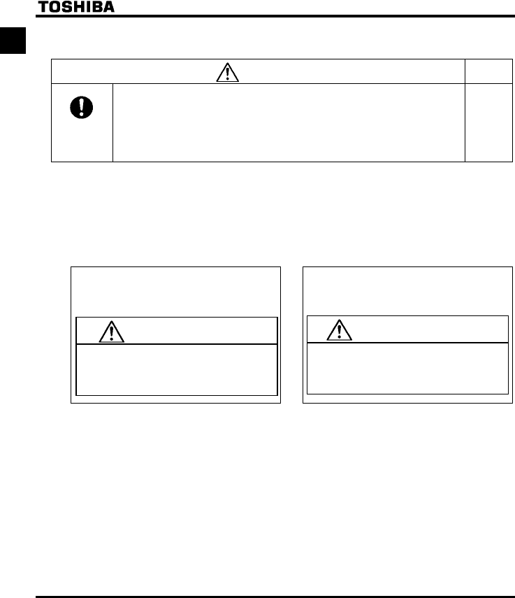
Attach warning labels
Shown here are examples of warning labels to prevent, in advance, accidents in relation to inverters, motors and other
equipment.
Be sure to affix the caution label where it is easily visible when selecting the auto-restart function (⇒ See section
6.12.1) or the retry function (⇒ See section 6.12.3).
If the inverter has been programmed for restart
sequence of momentary power failure, place warning
labels in a place where they can be easily seen and
read.
(Example of warning label)
If the retry function has been selected, place warning
labels in a location where they can be easily seen and
read.
(Example of warning label)
Warning (Functions
programmed for restart)
Do not go near motors and equipment.
Motors and equipment that have stopped
temporarily after momentary power failure will
restart suddenly after recovery.
Warning (Functions
programmed for retry)
Do not go near motors and equipment.
Motors and equipment that have stopped
temporarily after an alarm will restart suddenly
after the specified time has elapsed.

E6581381
7
II
II. Introduction
Thank you for your purchase of the Toshiba "TOSVERT VF-FS1” industrial inverter.
This is the Ver.100 / Ver.101 CPU version inverter.
Please be informed that CPU version will be frequently upgraded.
■Features
1. Built-in noise filter
1) All models in both the 200V and 400V series have a noise filter inside.
2) Can be compliant with European CE marking standard
3) Reduces space requirements and cuts down on time and labor needed in wiring.
2. Simple operation
1) Automatic functions (history, wizard, acceleration/deceleration time, and function programming)
Just by wiring the motor to the power supply allows instant operation without the need to program
parameters.
2) The RUN/STOP button and LOC/REM button allow easy operation.
3. Superior basic performance
1) Automatic energy-saving
2) Smooth operation : Reduced rotation ripple through the use of Toshiba's unique waveform formation.
3) Built-in current surge suppression circuit : Can be safely connected even if power load is low.
4) Maximum 200Hz high frequency output : Optimum for use with high speed motors such as those in
lumber machinery and milling machines.
5) Maximum carrier frequency : 16kHz quiet operation
Toshiba's unique PWM control reduces noise at low carrier.
4. Globally compatible
1) Compatible with 200V and 400V power supplies
2) Conforms to CE marking and with UL, CSA.
3) Sink/source switching of control input.
5. Options allow use with a wide variety of applications
•Internal communications devices (LonWorks®, BACnet®, Metasys® N2, Siemens APOGEETM FLN.)
•Extension panel/Parameter writer
•EMC noise reduction filter
•Other options are common to all models
6. Extended power range
•Wide range of powers up to 30kW for this class of inverter.

E6581381
i
Contents
I Safety precautions .........................................................................................................................................................1
II Introduction ....................................................................................................................................................................7
1. Read first........................................................................................................................................................................A-1
1.1 Check product purchase ....................................................................................................................................A-1
1.2 Contents of the product......................................................................................................................................A-2
1.3 Names and functions .........................................................................................................................................A-3
1.4 Notes on the application.....................................................................................................................................A-13
2. Connection.....................................................................................................................................................................B-1
2.1 Cautions on wiring..............................................................................................................................................B-1
2.2 Standard connections.........................................................................................................................................B-2
2.3 Description of terminals......................................................................................................................................B-5
3. Operations .....................................................................................................................................................................C-1
3.1 Simplified operation of the VF-FS1 ....................................................................................................................C-2
3.2 How to operate the VF-FS1 ...............................................................................................................................C-6
4. Basic VF-FS1 operations ...............................................................................................................................................D-1
4.1 Flow of status monitor mode ..............................................................................................................................D-2
4.2 How to set parameters .......................................................................................................................................D-3
5. Basic parameters ...........................................................................................................................................................E-1
5.1 Setting acceleration/deceleration time ...............................................................................................................E-1
5.2 Specifying an operation mode, using parameters ..............................................................................................E-4
5.3 Selection of operation mode ..............................................................................................................................E-7
5.4 Meter setting and adjustment.............................................................................................................................E-10
5.5 Standard default setting .....................................................................................................................................E-13
5.6 Forward/reverse run selection (Operation panel operation) ...............................................................................E-15
5.7 Maximum frequency...........................................................................................................................................E-16
5.8 Upper limit and lower limit frequencies...............................................................................................................E-16
5.9 Base frequency ..................................................................................................................................................E-17
5.10 Selecting control mode.......................................................................................................................................E-18
5.11 Manual torque boost - increasing torque boost at low speeds ...........................................................................E-24
5.12 Setting the electronic thermal.............................................................................................................................E-24
5.13 Preset-speed operation (speeds in 7 steps).......................................................................................................E-28
6. Extended parameters.....................................................................................................................................................F-1
6.1 Input/output parameters .....................................................................................................................................F-1
6.2 Input signal selection..........................................................................................................................................F-4

E6581381
ii
6.3 Terminal function selection ................................................................................................................................ F-5
6.4 Basic parameters 2............................................................................................................................................ F-13
6.5 Frequency priority selection............................................................................................................................... F-14
6.6 Operation frequency .......................................................................................................................................... F-22
6.7 DC braking......................................................................................................................................................... F-23
6.8 Auto-stop in case of lower-limit frequency continuous operation ....................................................................... F-24
6.9 Jump frequency-jumping resonant frequencies................................................................................................. F-25
6.10 Bumpless operation........................................................................................................................................... F-26
6.11 PWM carrier frequency ...................................................................................................................................... F-27
6.12 Trip-less intensification ...................................................................................................................................... F-31
6.13 Drooping control ................................................................................................................................................ F-39
6.14 Conducting PID control...................................................................................................................................... F-41
6.15 Setting motor constants..................................................................................................................................... F-45
6.16 Acceleration/deceleration time 2........................................................................................................................ F-50
6.17 Protection functions ........................................................................................................................................... F-54
6.18 Forced fire-speed control function ..................................................................................................................... F-68
6.19 Adjustment parameters...................................................................................................................................... F-69
6.20 Operation panel parameter................................................................................................................................ F-70
6.21 Communication function (Common serial)......................................................................................................... F-78
6.22 Parameters for options ...................................................................................................................................... F-83
6.23 Permanent magnetic motors.............................................................................................................................. F-83
7. Applied operation........................................................................................................................................................... G-1
7.1 Setting the operation frequency......................................................................................................................... G-1
7.2 Setting the operation mode................................................................................................................................ G-5
8. Monitoring the operation status ..................................................................................................................................... H-1
8.1 Status monitor mode.......................................................................................................................................... H-1
8.2 Display of trip information .................................................................................................................................. H-5
9. Measures to satisfy the standards ................................................................................................................................. I-1
9.1 How to cope with the CE directive .....................................................................................................................I-1
9.2 Compliance with UL Standard and CSA Standard ............................................................................................. I-5
10. Peripheral devices ......................................................................................................................................................... J-1
10.1 Selection of wiring materials and devices.......................................................................................................... J-1
10.2 Installation of a magnetic contactor ................................................................................................................... J-3
10.3 Installation of an overload relay ......................................................................................................................... J-4
10.4 Optional external devices .................................................................................................................................. J-5
11. Table of parameters and data ........................................................................................................................................ K-1
11.1 User parameters................................................................................................................................................ K-1
11.2 Basic parameters...............................................................................................................................................K-1
11.3 Extended parameters ........................................................................................................................................ K-4

E6581381
iii
12. Specifications................................................................................................................................................................L-1
12.1 Models and their standard specifications ...........................................................................................................L-1
12.2 Outside dimensions and mass ...........................................................................................................................L-4
13. Before making a service call - Trip information and remedies........................................................................................M-1
13.1 Trip causes/warnings and remedies...................................................................................................................M-1
13.2 Restoring the inverter from a trip........................................................................................................................M-5
13.3 If the motor does not run while no trip message is displayed.............................................................................M-6
13.4 How to determine the causes of other problems................................................................................................M-7
14. Inspection and maintenance ..........................................................................................................................................N-1
14.1 Regular inspection .............................................................................................................................................N-1
14.2 Periodical inspection ..........................................................................................................................................N-2
14.3 Making a call for servicing..................................................................................................................................N-5
14.4 Keeping the inverter in storage ..........................................................................................................................N-5
15. Warranty.........................................................................................................................................................................O-1
16. Disposal of the inverter ..................................................................................................................................................P-1
E6581381
A-1
1
1. Read first
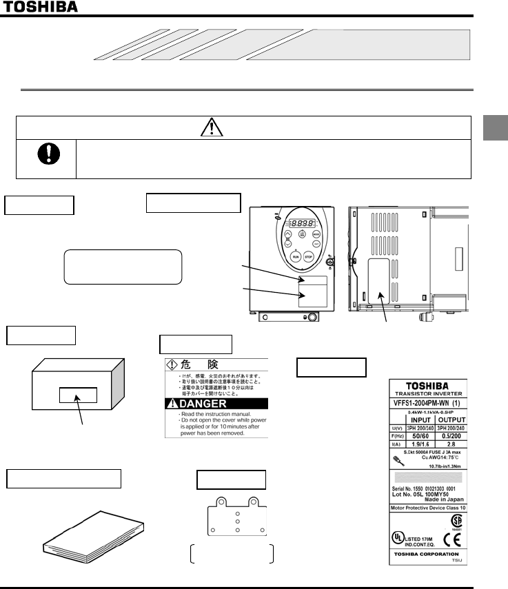
1.1 Check product purchase
Before using the product you have purchased, check to make sure that it is exactly what you ordered.
Warning
Mandatory
Use an inverter that conforms to the specifications of power supply and three-phase induction
motor being used. If the inverter being used does not conform to those specifications, not only will
the three-phase induction motor not rotate correctly, it may also cause serious accidents through
overheating and fire.
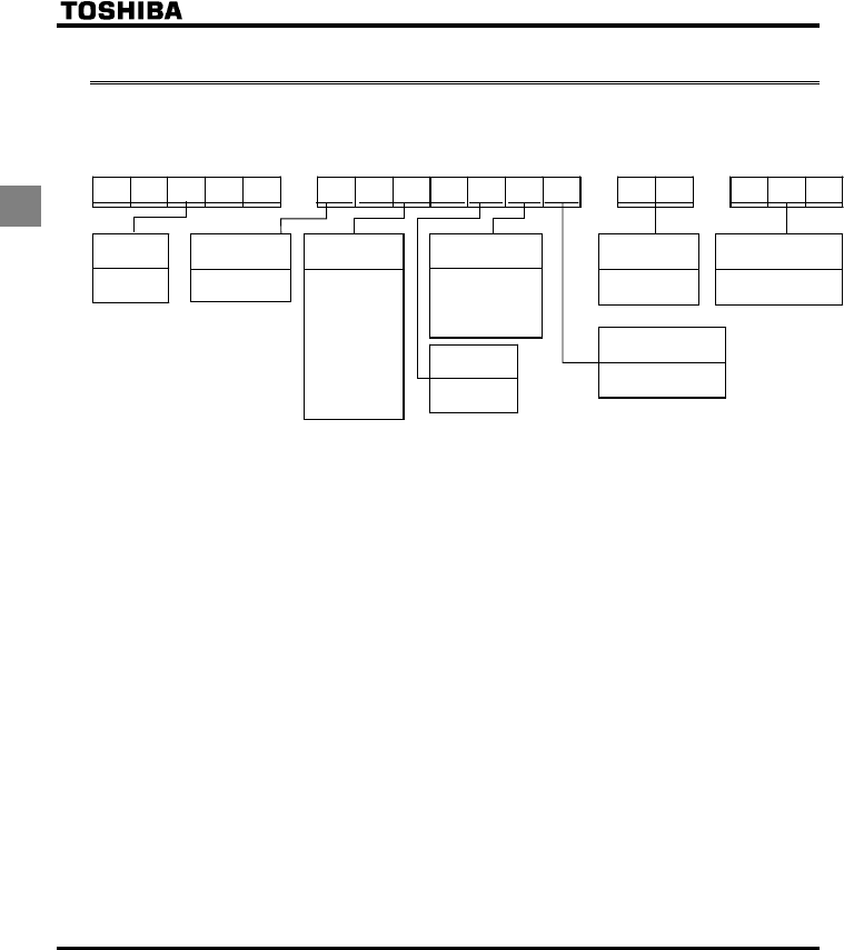
Related output
current
Power supply
Related input current
Inverter Type
Inverter rated output
capacity
Warning label
Power supply
Motor capacity
Series name
Rating label Inverter main unit
Carton box
Name plate
Warning label
VF-FS1
3PH-200/240V-0.75kW/1HP
Instruction manual
This manual
Type indication label
EMC plate
18.5kW or less of
WP models only
Name plate
Rating label
E6581381
A-2
1
1.2 Contents of the product
Explanation of the name plate label.
Type Form
VFFS1 -4007PLE-WN -A22
Model name
TOSVERT
VF-FS1series
Applicable motor
capacity
004 : 0.4kW
007 : 0.75kW
015 : 1.5kW
022 : 2.2kW
037 : 4.0kW
055 : 5.5kW
075 : 7.5kW
110 : 11kW
150 : 15kW
185 :18.5kW
220 : 22kW
300 : 30kW
Additional functions I
None: No filter inside
M: Built-in basic filter
L: Built-in
EMI class A filter
D: Built-in
EMI class B filter
Operation panel
P: Provided
Default interface
logic*
WN : Negative
WP : Positive
Special specification code
A:is the number
Input (AC) voltage
2 : 200V to 240V
4 : 380V to 480V
Additional functions II
None: Standard product
E: Enclosed type
* This code represents the factory default logic setting. You can switch from one input/output logic to the other using
slide switch SW4. ⇒ See section 2.3.2.
Warning: Always shut power off first then check the ratings label of inverter held in a cabinet.
E6581381
A-3
1
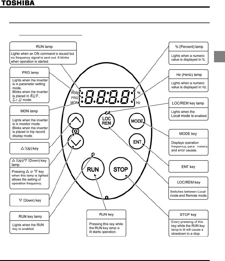
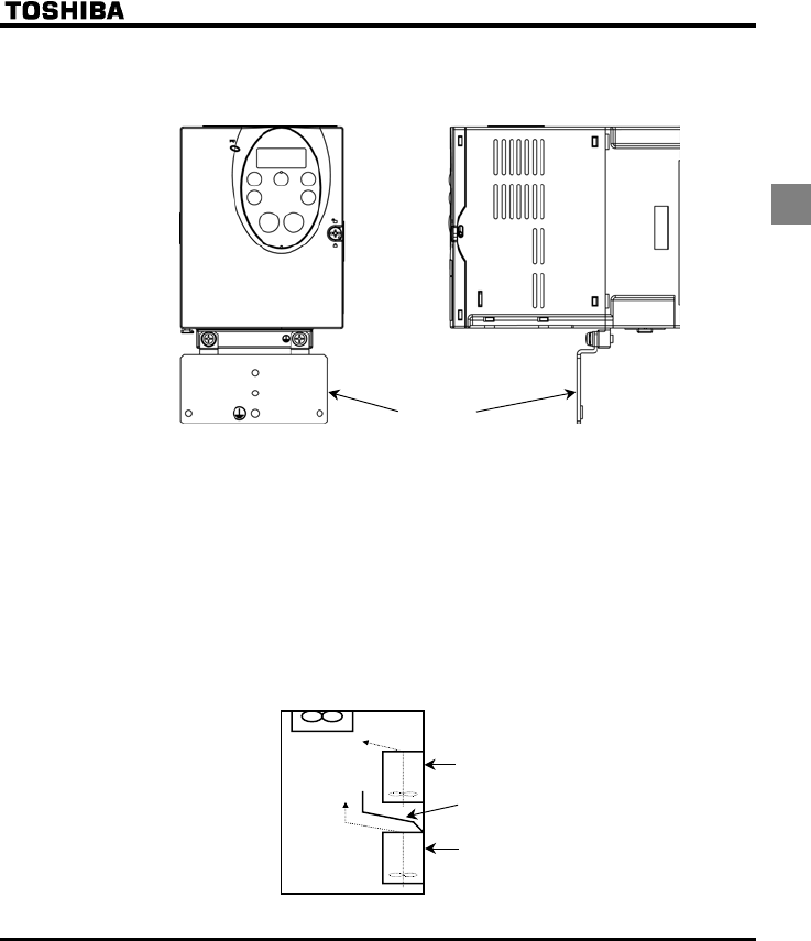
1.3 Names and functions
1.3.1 Outside view
[Operation panel]
E6581381
A-4
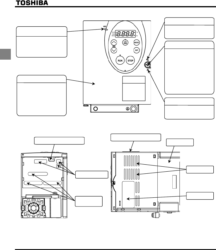
1
The front panel is unlocked when
the dot on the locking screw is on
this (upper) side.
The front panel is locked when the
dot on the locking screw is on this
(lower) side.
[Front]
Charge lamp
Front panel
Indicates that high voltage is still
present within the inverter. Do not
open the terminal board cover
while this is lit.
The front panel of the inverter or
terminal board
To avoid touching the terminal
board by mistake, be sure to close
the front panel before starting
operation.
Front panel locking screw
The inverter came with this
screw in the locked position.
So from this position, turn the
screw 90° counterclockwise to
unlock the front panel, or turn
it 90° clockwise to lock the
front panel.
The screw does not turn 360°. To
avoid damage to the screw, do
not use excessive force when
turning it.
Unlock position mark
Lock position mark
To
p
warnin
g
label Note
)
Colling fin
Communicatio Connector hole
Cnotrol cable port
Ventilation slit
Name plate
[Bottom] [Right side]
Main circuit
cable port
Note: Remove this seal and operate it at a current lower than the rated one when installing the inverter side by side with
other inverters where the ambient temperature will rise above 40°C.
E6581381
A-5
1
Example of the label
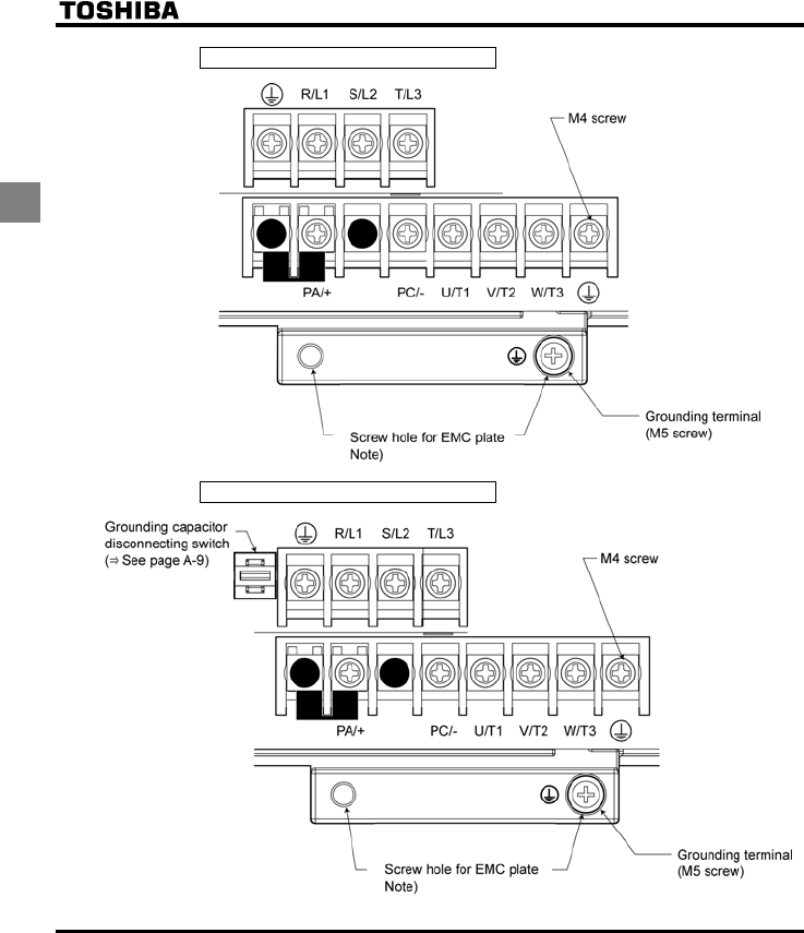
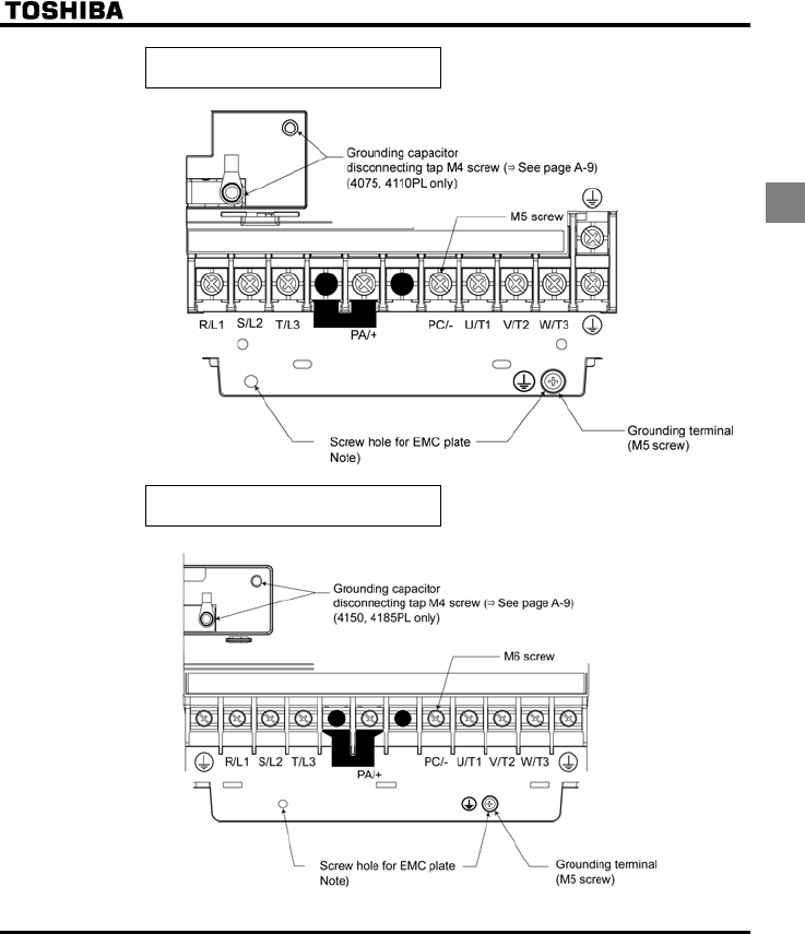
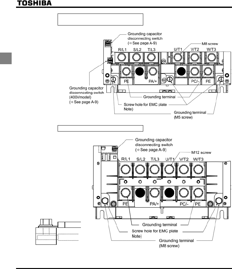
1.3.2 Power circuit and control circuit terminal boards
In case of the lug connector, cover the lug connector with insulated tube, or use the insulated lug connector.
1) Power circuit terminal board
In case of the lug connector, cover the lug connector with insulated tube, or use the insulated lug
connector.
Screw size tightening torque
M4 screw 1.3Nm 10.7lb y in
M5 screw 2.5Nm 22.3lb y in
M6 screw 4.5Nm 40.1lb y in
M8 screw 12Nm 106lb y in
M12 screw 41Nm 360lb y in
E6581381
A-6
1
VFFS1-2004 ∼ 2037PM
VFFS1-4004 ∼ 4055PL
Note: EMC plate is supplied as standard.
E6581381
A-7
1
VFFS1-2055, 2075PM
-4075, 4110PL
VFFS1-2110 ∼ 2185PM
-4150 ∼ 4185PL
Note: EMC plate is supplied as standard.
E6581381
A-8
1
VFFS1-2220PM
-4220, 4300PL
VFFS1-2300PM
A
B
Each main circuit terminal has the
structure shown in the figure below.
Connect a cable to part A if it has a
ring terminal, or to part B if it has no
terminal (bare wire).
Parts A and B accommodate different
sizes of cables, so consult the cable
size list for the size of cable
connectable to each part.
Note: EMC plate is supplied as standard.
E6581381
A-9
1
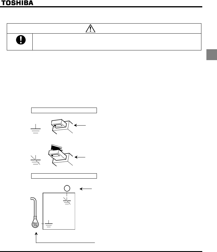
2) Grounding capacitor disconnecting switch and taps
Warning
Mandatory
The grounding capacitor disconnecting tap is provided with a protection cover. To avoid shock hazards,
always attach the cover after connecting or disconnecting the capacitor to or from the tap.
Every three-phase 400V model has a built-in high-attenuation noise filter, which is grounded through a
capacitor.
If you want to disconnect the capacitor from the grounding line to reduce the amount of leakage current,
you can do so easily using the switch or tap. Keep in mind, however, that disconnecting the capacitor
from the grounding line causes the inverter to become non-compliant with the EMC directive. Also note
that the inverter must always be turned off before the capacitor is disconnected or reconnected.
Note: In case of three phase 400V-5.5kW or less model, if you disconnect the capacitor from ground,
set the parameter of carrier frequency H to 6kHz with motor cable length 30m or less.
5.5kW or less, 22kW or more: Switch
7.5∼18.5kW: Tap
To connect the capacitor to ground, push this switch.
(Factory default position)
To disconnect the capacitor from ground, pull up this switch.
To disconnect the capacitor from ground, connect the lug terminal
to this tap.
To connect the capacitor to ground, connect the lug terminal to
this tap. (Factory default setting)
E6581381
A-10
1
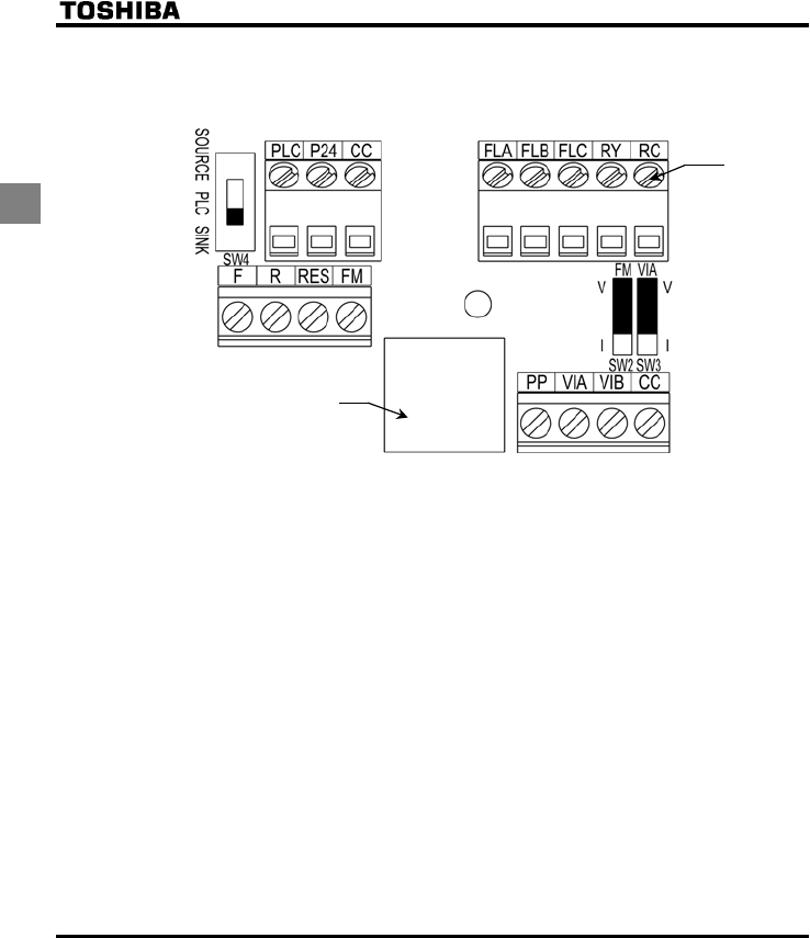
3) Control circuit terminal board
The control circuit terminal board is common to all equipment.
M3 screw
(0.5N•m)
Connector for common
serial communications
and option (RJ45)
Wire size Factory default settings of slide switches
Solid wire: 0.3 ∼ 1.5 (mm2) SW4: SINK (Negative) side (WN type)
SOURCE (Positive) side (WP type)
Stranded wire: 0.3 ∼ 1.5 (mm2) FM (SW2): V side
(AWG 22 ∼ 16) VIA (SW3): V side
Sheath strip length: 6 (mm)
Screwdriver: Small-sized flat-blade screwdriver
(Blade thickness: 0.4 mm or less, blade width: 2.5 mm or less)
⇒ See section 2.3.2 for details on all terminal functions.
E6581381
A-11
1
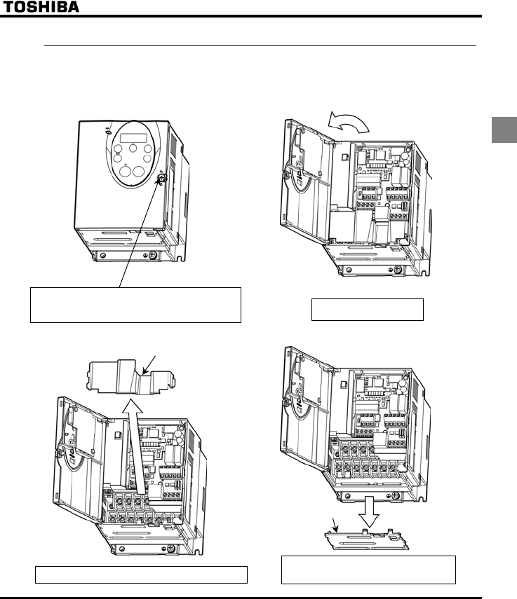
1.3.3
How to open the front (terminal board) cover-18.5kW or less
To wire the terminal board, remove the front lower cover in line with the steps given below.
Turn the locking screw on the right side of the front panel 90°
counterclockwise to align the dot on the screw with the unlock
position mark (upper side). To avoid damage to the screw, do
not apply excessive force to turn the screw more than 90 degrees.
Pull the front panel toward you
and swing it open to the left.
Terminal board cover
Remove the terminal board cover by pulling it up toward you.
Remove the wiring port cover by pulling it down,
pass cables through the wiring port, and connect
the cables to the terminal board.
Wiring port cover
(1) (2)
(3) (4)
E6581381
A-12
1
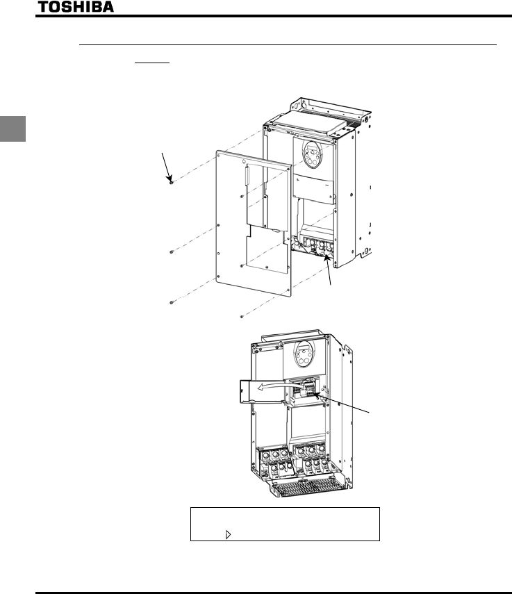
1.3.4 How to open the front (terminal board) cover-22kW or
more
To wire the main circuit terminal board for models 22kW or more, remomve the front cover.
Remove the screw
Maincircuit terminal board
Control circuit terminal board
Open the control circuit terminal board cover.
* To open the cover, lift it with your finger placed
at the part on the right side of the cover.
E6581381
A-13
1
1.4 Notes on the application
1.4.1 Motors
When the VF-FS1 and the motor are used in conjunction, pay attention to the following items.
Warning
Mandatory
Use an inverter that conforms to the specifications of power supply and three-phase induction motor
being used. If the inverter being used does not conform to those specifications, not only will the three-
phase induction motor not rotate correctly, but it may cause serious accidents through overheating and
fire.
Comparisons with commercial power operation.
The VF-FS1 Inverter employs the sinusoidal PWM system. However, the output voltage and output
current are not perfect sine waves, they have a distorted wave that is close to sinusoidal waveform.
This is why compared to operation with a commercial power there will be a slight increase in motor
temperature, noise and vibration.
Operation in the low-speed area
When running continuously at low speed in conjunction with a general purpose motor, there may be a
decline in that motor's cooling effect. If this happens, operate with the output decreased from rated load.
To carry out low-speed operation continuously at the rated torque, we recommend to use a inverter
rated motor or a forced cooled motor designed for use with an inverter. When operating in conjunction
with a inverter rated motor, you must change the inverter's motor overload protection level to VF motor
use (QNO).
Adjusting the overload protection level
The VF-FS1 Inverter protects against overloads with its overload detection circuits (electronic thermal).
The electronic thermal's reference current is set to the inverter's rated current, so it must be adjusted in
line with the rated current of the general purpose motor being used in combination.
High speed operation at and above 60Hz
Operating at frequencies greater than 60Hz will increase noise and vibration. There is also a possibility
this will exceed the motor's mechanical strength limits and the bearing limits so you should inquire to
the motor's manufacturer about such operation.
Method of lubricating load mechanisms
Operating an oil-lubricated reduction gear and gear motor in the low-speed areas will worsen the
lubricating effect. Check with the manufacturer of the reduction gear to find out about operable gearing
area.

E6581381
A-14
1
Low loads and low inertia loads
The motor may demonstrate instability such as abnormal vibrations or overcurrent trips at light loads of
50 % or under of the load percentage, or when the load's inertia moment is extremely small. If that
happens reduce the carrier frequency.
Occurrence of instability
Unstable phenomena may occur with the load and motor combinations shown below.
⋅Combined with a motor that exceeds applicable motor ratings recommended for the inverter
⋅Combined with special motors
To deal with the above lower the settings of inverter carrier frequency.
⋅Combined with couplings between load devices and motors with high backlash
When using the inverter in the above combination, use the S-pattern acceleration/deceleration function,
or when vector control is selected, adjust the speed control response/stability factor or switch to V/F
control mode.
⋅Combined with loads that have sharp fluctuations in rotation such as piston movements
In this case, please do not use this inverter.
Braking a motor when cutting off power supply
A motor with its power cut off goes into free-run, and does not stop immediately. To stop the motor
quickly as soon as the power is cut off install an auxiliary brake. There are different kinds of brake
devices, both electrical and mechanical. Select the brake that is best for the system.
Load that produces regenerative torque
Do not use the inverter in combination with a load, such as an air conditioner, that produces
regenerative torque. Or the overvoltage or overcurrent protection circuit of the inverter may be activated,
causing the inverter to trip. If overvoltage tripping occurs during deceleration, lengthen the deceleration
time.
E6581381
A-15
1
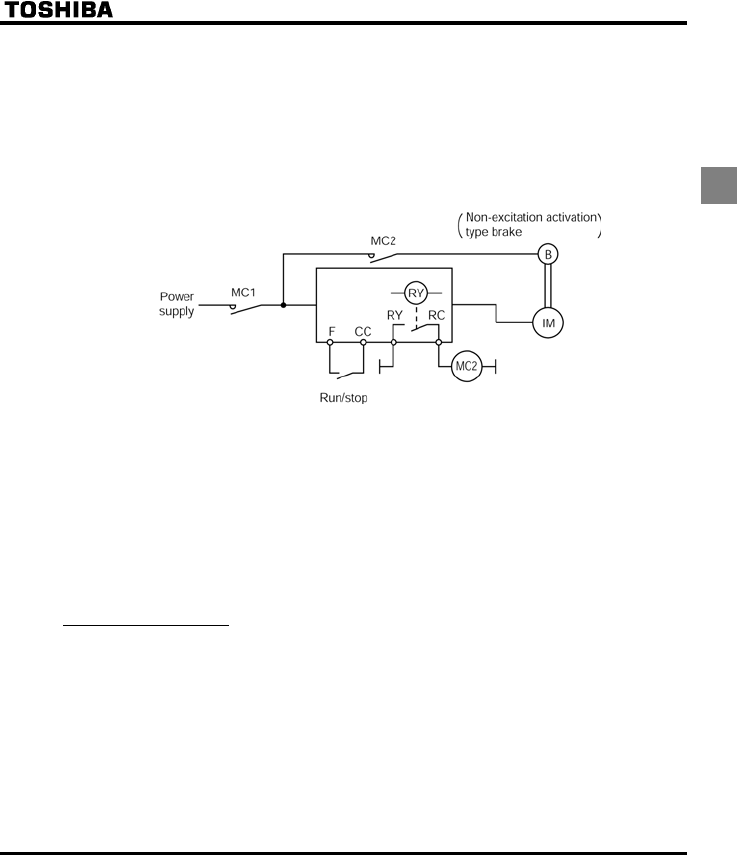
Braking motor
When using a braking motor, if the braking circuit is directly connected to the inverters's output
terminals, the brake cannot be released because of the lowered starting voltage. Therefore, when
using a braking motor, connect the braking circuit to the inverter's power supply side, as shown in the
figure below. Usually, braking motors produce larger noise in low speed ranges.
Note: In the case of the circuit shown on the below, assign the function of detecting low-speed signals
to the RY and RC terminals. Make sure the parameter H is set to (factory default
setting).
Measures to protect motors against surge voltages
In a system in which a 400V-class inverter is used to control the operation of a motor, very high surge
voltages may be produced. When applied to the motor coils repeatedly for a long time, may cause
deterioration of their insulation, depending on the cable length, cable routing and types of cables used.
Here are some examples of measures against surge voltages.
(1) Lower the inverter’s carrier frequency.
(2) Set the parameter H (Carrier frequency control mode selection) to or .
(3) Use a motor with high insulation strength.
(4) Insert an AC reactor or a surge voltage suppression filter between the inverter and the motor.
1.4.2 Inverters
Protecting inverters from overcurrent
The inverter has an overcurrent protection function. The programmed current level is set to the
inverter's maximum applicable motor. If the motor used has a small capacity, the overcurrent level and
the electronic thermal protection must be readjusted. If adjustment is necessary, see 5.12, and make
adjustments as directed.
Inverter capacity
Do not use a small-capacity (kVA) inverter to control the operation of a large-capacity motor (two-class
or more larger motor), no matter how light the load is. Current ripple will raise the output peak current
making it easier to set off the overcurrent trip.
E6581381
A-16
1
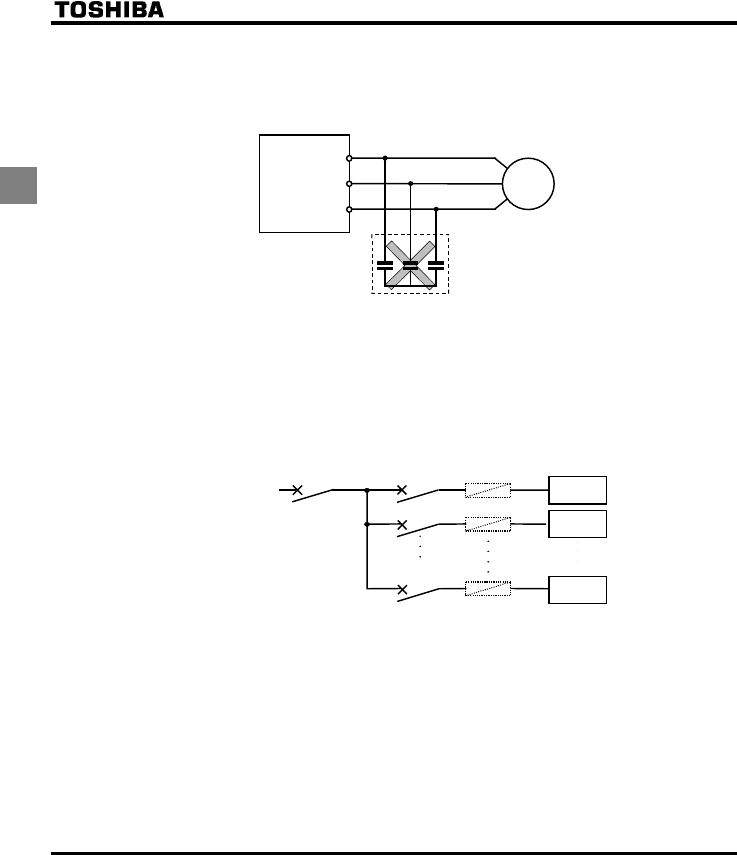
Power factor correction capacitor
Power factor correction capacitors cannot be installed on the output side of the inverter. When a motor
is run that has a power factor correction capacitor attached to it, remove the capacitors. This can cause
inverter malfunction trips and capacitor destruction.
Remove the power factor correction
capacitor and surge absorber
Power factor correction capacitor
U
/
T1
V
/
T2
W
/
T3
Inverte
r
IM
Operating at other than rated voltage
Connections to voltages other than the rated voltage described in the rating label cannot be made. If a
connection must be made to a power supply other than one with rated voltage, use a transformer to
raise or lower the voltage to the rated voltage.
Circuit breaking when two or more inverters are used on the same power line.
MCCB1
MCCBn
+
1
MCCB3
MCCB2
INV1
INV2
INVn
(circuit breaking fuse)
Breaking of selected inverter
There is no fuse in the inverter's main circuit. Thus, as the diagram above shows, when more than one
inverter is used on the same power line, you must select interrupting characteristics so that only the
MCCB2 will trip and the MCCB1 will not trip when a short occurs in the inverter (INV1). When you
cannot select the proper characteristics install a circuit interrupting fuse between the MCCB2 and the
INV1.
If power supply distortion is not negligible
If the power supply distortion is not negligible because the inverter shares a power distribution line with
other systems causing distorted waves, such as systems with thyristors or large-capacity inverters,
install an input reactor to improve the input power factor, to reduce higher harmonics, or to suppress
external surges.
E6581381
A-17
1
■Disposal
If an inverter is no longer usable, dispose of it as industrial waste.
1.4.3 What to do about the leak current
Warning
Current may leak through the inverter's input/output wires because of insufficient electrostatic capacity on the motor with
bad effects on peripheral equipment.
The leakage current’s value is affected by the carrier frequency and the length of the input/output wires. Test and adopt
the following remedies against leak current.
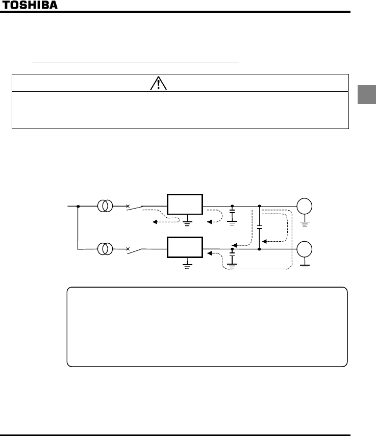
(1) Effects of leak current across ground
Leakage current may flow not just through the inverter system but also through ground wires to other
systems. Leakage current will cause earth leakage breakers, leakage current relays, ground relays, fire
alarms and sensors to operate improperly, and it will cause superimposed noise on the CRT screen or
display of incorrect current detection with the CT.
Power
supply
ELCB
Inverter
Inverter
M
M
ELCB
Leakage current path across ground
Remedies:
1.If there is no radio-frequency interference or similar problem, detach the built-in noise filter
capacitor, using the grounding capacitor disconnecting switch or tap. ⇒ See section 1.3.2-2.
2.Reduce PWM carrier frequency.
The setting of PWM carrier frequency is done with the parameter H.
Although the electromagnetic noise level is reduced, the motor acoustic noise is increased.
3. Use high frequency remedial products for earth leakage breakers.
E6581381
A-18
1
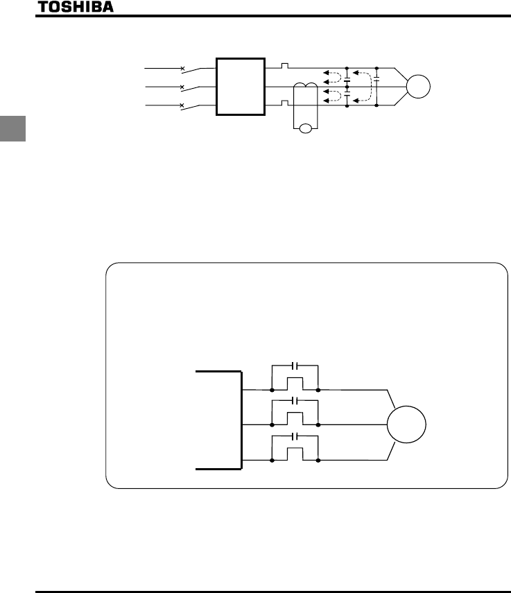
(2) Affects of leakage current across lines
Power
supply
Inverter
Thermal relays
CT
A
M
Leakage current path across wires
(1) Thermal relays
The high frequency component of current leaking into electrostatic capacity between inverter out-
put wires will increase the effective current values and make externally connected thermal relays
operate improperly. If the wires are more than 50 meters long, it will be easy for the external
thermal relay to operate improperly with models having motors of low rated current (several
A(ampere) or less), especially the 400V class low capacity (5.5kW or less) models, because the
leak current will increase in proportion to the motor rating.
Remedies:
1.Use the electronic thermal built into the inverter. ⇒ See section 5.12.
The setting of the electronic thermal is done using parameter QNO, VJT.
2.Reduce the inverter's PWM carrier frequency. However, that will increase the motor's magnetic
noise.
The setting of PWM carrier frequency is done with the parameter H. ⇒ See section 6.11.
3.This can be improved by installing 0.1µ~0.5µF - 1000V film capacitor to the input/output terminals of
each phase in the thermal relay.
U/T1
V/T2
W/T3
IM
Thermal rela
y
s
E6581381
A-19
1
(2) CT and ammeter
If a CT and ammeter are connected externally to detect inverter output current, the leak current's high
frequency component may destroy the ammeter. If the wires are more than 50 meters long, it will be
easy for the high frequency component to pass through the externally connected CT and be
superimposed on and burn the ammeter with models having motors of low rated current (several
A(ampere) or less), especially the 400V class low capacity (5.5kW or less) models, because the leak
current will increase in proportion to the motor's rated current.
Remedies:
1.Use a meter output terminal in the inverter control circuit.
The load current can be output on the meter output terminal (FM). If the meter is connected, use an
ammeter of 1mAdc full scale or a voltmeter of 7.5V-1mA full scale.
0-20mAdc (4-20mAdc) can be also output. ⇒ See section 5.4.
2.Use the monitor functions built into the inverter.
Use the monitor functions on the panel built into the inverter to check current values.
⇒See section 8.1.1.
1.4.4 Installation
■Installation environment
The VF-FS1 Inverter is an electronic control instrument. Take full consideration to installing it in the proper
operating environment.
Danger
Prohibited
•Do not place any inflammable substances near the VF-FS1 Inverter.
If an accident occurs in which flame is emitted, this could lead to fire.
Mandatory
•Operate under the environmental conditions prescribed in the instruction manual.
Operations under any other conditions may result in malfunction.
Warning
Prohibited
•Do not install the VF-FS1 Inverter in any location subject to large amounts of vibration.
This could cause the unit to fall, resulting in bodily injury.
Mandatory
•Check to make sure that the input power voltage is +10%, -15% of the rated power voltage written on
the rating label (±10% when the load is 100% in continuous operation) If the input power voltage is not
+10%, -15% of the rated power voltage (±10% when the load is 100% in continuous operation) this
may result in fire.
E6581381
A-20
1
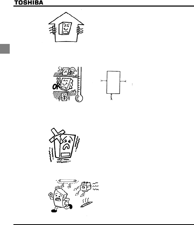
•Do not install in any location of high temperature, high humidity,
moisture condensation and freezing and avoid locations where
there is exposure to water and/or where there may be large
amounts of dust, metallic fragments and oil mist.
•Do not install in any location where corrosive gases or grinding
fluids are present.
•Operate in areas where ambient temperature ranges from -10°C to 60°C.
When installing the inverter where the ambient temperature will rise above 40°C, remove the label
(seal) from the top and operate it at a current lower than the rated one.
5cm 5cm
Measurement position
Measurement position
5cm
Note: The inverter is a heat-emitting body. Make sure proper space and ventilation is provided when
installing in the cabinet. When installing inside a cabinet, we recommend the top seal peeled off
although 40°C or less.
•Do not install in any location that is subject to large amounts of vibration.
Note: If the VF-FS1 Inverter is installed in a location that is subject
to vibration, anti-vibration measures are required. Please
consult with Toshiba about these measures.
•If the VF-FS1 Inverter is installed near any of the equipment listed below, provide measures to insure
against errors in operation.
Solenoids: Attach surge suppressor on coil.
Brakes: Attach surge suppressor on coil.
Magnetic contactors: Attach surge suppressor on coil.
Fluorescent lights: Attach surge suppressor on coil.
Resistors: Place far away from VF-FS1 Inverter.
Resistors
E6581381
A-21
1
■How to install
Danger
Prohibited
•Do not install or operate the inverter if it is damaged or any component is missing.
This can result in electric shock or fire. Please consult your local sales agency for repairs. Call your
local sales agency for repairs.
Mandatory
•Mount the inverter on a metal plate.
The rear panel gets very hot. Do not install in an inflammable object, this can result in fire.
•Do not operate with the front panel cover removed.
This can result in electric shock.
•An emergency stop device must be installed that fits with system specifications (e.g. shut off input
power then engage mechanical brake).
Operation cannot be stopped immediately by the inverter alone, thus risking an accident or injury.
•All options used must be those specified by Toshiba.
The use of any other option may result in an accident.
Warning
Mandatory
•The main unit must be installed on a base that can bear the unit's weight.
If the unit is installed on a base that cannot withstand that weight, the unit may fall resulting in injury.
•If braking is necessary (to hold motor shaft), install a mechanical brake.
The brake on the inverter will not function as a mechanical hold, and if used for that purpose, injury
may result.
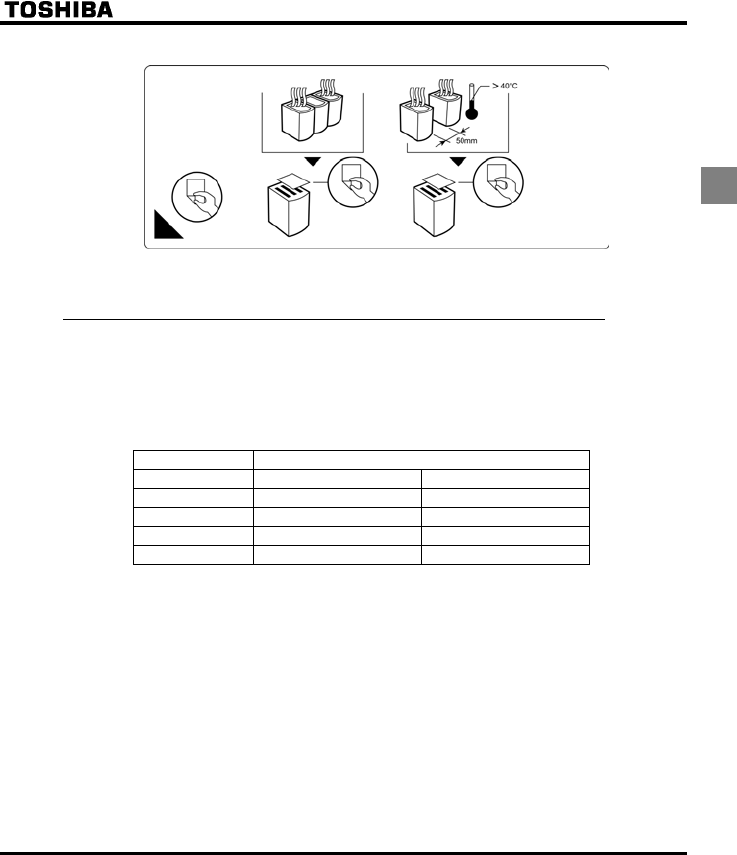
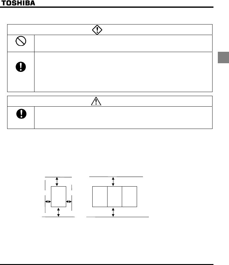
Install the inverter in a well-ventilated indoor place and mount it on a flat metal plate in portrait orientation.
If you are installing more than one inverter, the separation between inverters should be at least 5 centimeters,
and they should be arranged in horizontal rows. If the inverters are horizontally arranged with no space
between them (side-by-side installation), peel off the ventilation seals on top of the inverter. It is necessary to
decrease the current if the inverter is operated at over 40°C.
•Standard installation •Side-by-side installation
5 cm or more 5 cm or more
10 cm or more
10 cm or more
Remove seals on top
VF-FS1 VF-FS1 VF-FS1 VF-FS1
10 cm or more
10 cm or more
The space shown in the diagram is the minimum allowable space. Because air cooled equipment has cooling
fans built in on the top or bottom surfaces, make the space on top and bottom as large as possible to allow
for air passage.
Note: Do not install in any location where there is high humidity or high temperatures and where there are
large amounts of dust, metallic fragments and oil mist.
E6581381
A-22
1
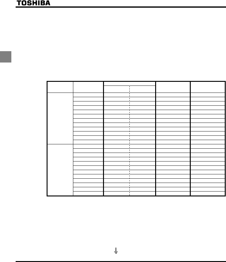
■Calorific values of the inverter and the required ventilation
About 5% of the rated power of the inverter will be lost as a result of conversion from AC to DC or from DC to
AC. In order to suppress the rise in temperature inside the cabinet when this loss becomes heat loss, the
interior of the cabinet must be ventilated and cooled.
The amount of forcible air-cooling ventilation required and the necessary heat discharge surface quantity
when operating in a sealed cabinet according to motor capacity are as follows.
Note1: The heat loss for the optional external devices (input reactor, radio noise reduction filters, etc.) is not
included in the calorific values in the table
Note2: Case of 100% Load Continuation operation.
Calorific Values (w)
Voltage class
Operating motor
capacity
(kW)
Carrier frequency
8kHz
Carrier frequency
12kHz
Amount of forcible air
cooling ventilation required
(m3/min)
Heat discharge surface
area required for sealed
storage cabinet(m2)
0.4 - 44 0.25 0.88
0.75 - 63 0.36 1.26
1.5 - 101 0.58 2.02
2.2 - 120 0.68 2.4
4.0 - 193 1.1 3.86
5.5 - 249 1.42 4.98
7.5 - 346 1.97 6.92
11 - 459 2.62 9.18
15 - 629 3.59 12.58
18.5 698 - 3.98 13.96
22 763 - 4.35 15.26
Three-Phase
200V class
30 1085 - 6.18 21.7
0.4 - 45 0.26 0.9
0.75 - 55 0.31 1.1
1.5 - 78 0.44 1.56
2.2 - 103 0.59 2.06
4.0 - 176 1.0 3.52
5.5 - 215 1.23 4.3
7.5 - 291 1.66 5.82
11 - 430 2.45 8.6
15 - 625 3.56 12.5
18.5 603 - 3.44 12.06
22 626 - 3.57 12.52
Three-Phase
400V class
30 847 - 4.83 16.94
■Panel designing taking into consideration the effects of noise
The inverter generates high frequency noise. When designing the control panel setup, consideration must be
given to that noise. Examples of measures are given below.
•Wire so that the main circuit wires and the control circuit wires are separated. Do not place them in the
same conduit, do not run them parallel, and do not bundle them.
•Provide shielding and twisted wire for control circuit wiring.
•Separate the input (power) and output (motor) wires of the main circuit. Do not place them in the same
conduit, do not run them parallel, and do not bundle them.
•Ground the inverter ground terminals ( ).
E6581381
A-23
1
•Install surge suppressor on any magnetic contactor and relay coils used around the inverter.
•Install noise filters if necessary.
•Install EMC plate and use shielded wires.
EMC plate
■Installing more than one unit in a cabinet
If you are installing two or more inverters in one cabinet, pay attention to the following.
•Inverters may be installed side by side with each other with no space left between them.
•When installing inverters side by side, detach the caution label on the top surface of each inverter and
use them where the ambient temperature will not rise above 40°C.
When using inverters where the ambient temperature will rise above 40°C, leave a space of 5 cm or
more between them and remove the caution label from the top of each inverter, and operate each
inverter at a current lower than the rated one.
•Ensure a space of at least 20 centimeters on the top and bottom of the inverters.
•Install an air deflecting plate so that the heat rising up from the inverter on the bottom does not affect the
inverter on the top.
Ventilation fan
Inverter
A
ir deflecting plate
Inverter
E6581381
B-1
2
2. Connection
Danger
Disassembly
prohibited
•Never disassemble, modify or repair.
This can result in electric shock, fire and injury. For repairs, call your sales agency.
Prohibited
•Don't stick your fingers into openings such as cable wiring hole and cooling fan covers.
This can result in electric shock or other injury.
•Don't place or insert any kind of object into the inverter (electrical wire cuttings, rods, wires). This can
result in electric shock or fire.
•Do not allow water or any other fluid to come in contact with the inverter.
That may result in electric shock or fire.
Warning
Prohibited
•When transporting or carrying, do not hold by the front panel covers.
The covers may come off and the unit will drop out resulting in injury.
2.1 Cautions on wiring
Danger
Prohibited
•Never remove the front cover when power is on or open door if enclosed in a cabinet.
The unit contains many high voltage parts and contact with them will result in electric shock.
Mandatory
•Turn power on only after attaching the front cover or closing door if enclosed in a cabinet.
If power is turned on without the front cover attached or closing door if enclosed in a cabinet. This can
result in electric shock or other injury.
•Electrical construction work must be done by a qualified expert.
Connection of input power by someone who does not have that expert knowledge may result in fire or
electric shock.
•Connect output terminals (motor side) correctly.
If the phase sequence is incorrect, the motor will operate in reverse and that may result in injury.
•Wiring must be done after installation.
If wiring is done prior to installation that may result in injury or electric shock.
•The following steps must be performed before wiring.
(1) Shut off all input power.
(2) Wait at least ten minutes and check to make sure that the charge lamp is no longer lit.
(3) Use a tester that can measure DC voltage (800VDC or more), and check to make sure that the
voltage to the DC main circuits (across PA/+ and PC/-) is 45V or less.
If these steps are not properly performed, the wiring will cause electric shock.
•Tighten the screws on the terminal board to specified torque.
If the screws are not tightened to the specified torque, it may lead to fire.
E6581381
B-2
2
Danger
Be Grounded
•Ground must be connected securely.
If the ground is not securely connected, it could lead to electric shock or fire when a malfunction or
current leak occurs.
Warning
Prohibited
•Do not attach devices with built-in capacitors (such as noise filters or surge absorber) to the output
(motor side) terminal.
This could cause a fire.
■Preventing radio noise
To prevent electrical interference such as radio noise, separately bundle wires to the main circuit's power
terminals (R/L1, S/L2, T/L3) and wires to the motor terminals (U/T1, V/T2, W/T3).
■Control and main power supply
The control power supply and the main circuit power supply for the VF-FS1 are the same.
⇒ See section 6.17.3.
If a malfunction or trip causes the main circuit to be shut off, control power will also be shut off. When
checking the cause of the malfunction or the trip, use the trip holding retention selection parameter.
■Wiring
•Because the space between the main circuit terminals is small use sleeved pressure terminals for the
connections. Connect the terminals so that adjacent terminals do not touch each other.
•For ground terminal use wires of the size that is equivalent to or larger than those given in table 10.1
and always ground the inverter (200V voltage class: D type ground, 400V class: C type ground).
Use as large and short a ground wire as possible and wire it as close as possible to the inverter.
•For the sizes of electric wires used in the main circuit, see the table in 10.1.
•The length of the main circuit wire in 10.1 should be no longer than 30 meters. If the wire is longer than
30 meters, the wire size (diameter) must be increased.
2.2 Standard connections
Danger
Prohibited
•Do not connect input power to the output (motor side) terminals (U/T1, V/T2, W/T3).
Connecting input power to the output could destroy the inverter or cause a fire.
•Do not insert a resistor between DC terminals (between PA/+ and PC/-).
It could cause a fire.
•First shut off input power and wait at least 10 minutes before touching wires on equipment (MCCB) that
is connected to inverter power side.
Touching the wires before that time could result in electric shock.
E6581381
B-3
2
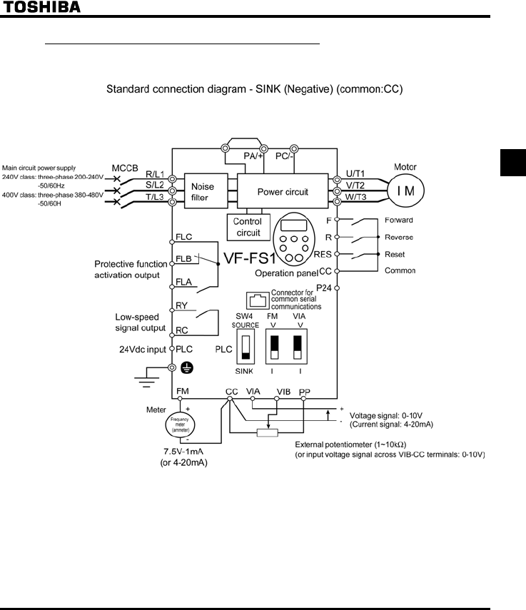
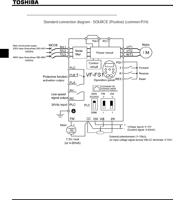
2.2.1 Standard connection diagram 1
This diagram shows a standard wiring of the main circuit.
E6581381
B-4
2
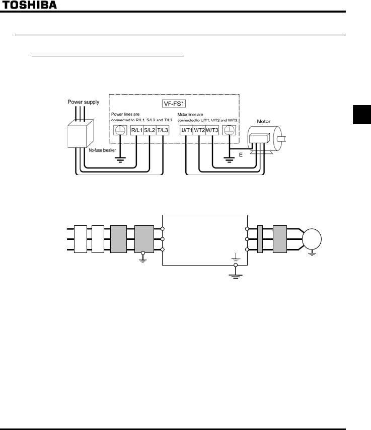
2.2.2 Standard connection diagram 2
E6581381
B-5
2
2.3 Description of terminals
2.3.1 Power circuit terminals
This diagram shows an example of wiring of the main circuit. Use options if necessary.
■Power supply and motor connections
■Connections with peripheral equipment
Motor
Power
supply
Inverter
Surge suppression
filter
No-fuse
braker
R/L1
S/L2
T/L3
V/T2
U/T1
W/T3
IM
Magnetic
connector
Input AC
reactor
noise reduction
filter
Zero-phase
reactor
E6581381
B-6
2
■Power circuit
Terminal symbol Terminal function
Grounding terminal for connecting inverter. There are 3 terminals in total. 2 terminals in
the terminal board, 1 terminal in the cooling fin.
R/L1,S/L2,T/L3 200V class: three-phase 200 to 240V-50/60Hz
400V class: three-phase 380 to 480V-50/60Hz
U/T1,V/T2,W/T3 Connect to a (three-phase induction) motor.
PA/+, PC/-
PA/+ terminal: Positive potential terminal for the internal DC main circuit
PC/- terminal: Negative potential terminal for the internal DC main circuit
DC power can be supplied through the PA/+ and PC/- terminals.
The arrangement of power circuit terminals are different from each range.
⇒ See section 1.3.2.1) about the arrangement of power circuit terminals.
2.3.2 Control circuit terminals
The control circuit terminal board is common to all equipment.
Regarding to the function and specification of each terminal, please refer to the following table.
⇒ See section 1.3.2.3) about the arrangement of control circuit terminals.
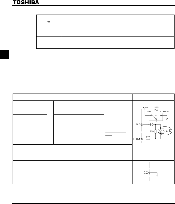
■Control circuit terminals
Terminal
symbol Input/output Function Electrical
specifications Inverter internal circuits
F Input
Shorting across F-CC causes
forward rotation; open causes slow-
down and stop. (When ST is always
ON)
R Input
Shorting across R-CC causes
reverse rotation; open causes slow-
down and stop. (When ST is always
ON)
RES Input
Multifunction programmable
contact in
p
ut
This inverter protective function is
disabled if RES are CC is connected.
Shorting RES and CC has no effect
when the inverter is in a normal
condition.
No voltage
contact input
24Vdc-5mA or less
*Sink/Source/PLC
selectable using
SW4
PLC Input
(common)
External 24Vdc power input
When the source logic is used, a common
terminal is connected.
24VDC
(Insulation
resistance: DC50V)
Factory default setting
WN type : SINK side
WP type : SOURCE side
CC Common to
Input/output
Control circuit's equipotential terminal (2
terminals)
E6581381
B-7
2
Terminal
symbol Input/output Function Electrical
specifications Inverter internal circuits
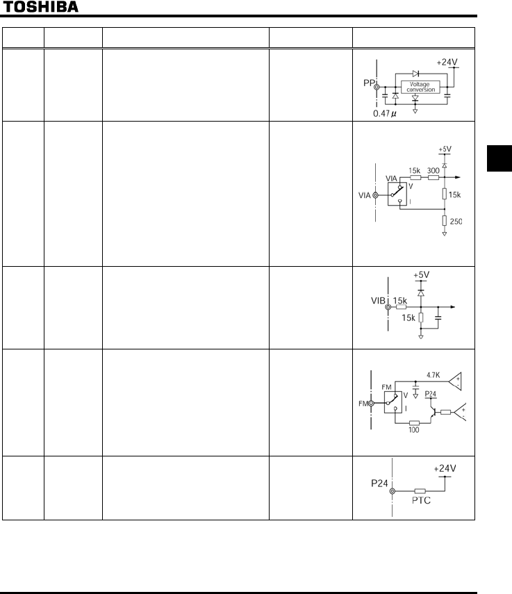
PP Output Analog power supply output
10Vdc
(permissible load
current: 10mA)
VIA Input
Multifunction programmable analog input.
Factory default setting: 0~10Vdc/0~60Hz
(0~50Hz) frequency input.
The function can be changed to
4~20mAdc (0~20mA) current input by
flipping the VIA (SW3) dip switch to the I
position.
By changing parameter setting, this
terminal can also be used as a
multifunction programmable contact input
terminal. When using the sink logic, be
sure to insert a resistor between P24-VIA
(4.7 kΩ-1/2 W). Also move the VIA (SW3)
dip switch to the V position.
10Vdc
(internal impedance:
30kΩ)
4-20mA
(internal impedance:
250Ω)
VIB Input
Multifunction programmable analog input.
Standard default setting: 0~10Vdc/0~60Hz
(0~50Hz) frequency input.
PTC thermal input ⇒ See section 6.17.15.
10Vdc
(internal
impedance: 30kΩ)
FM Output
Multifunction programmable analog
output. Standard default setting: output
frequency.
The function can be changed to 0-20mAdc
(4-20mA) current output by flipping the FM
(SW2) slide switch to the I position.
1mAdc full-scale
ammeter or 7.5Vdc
(10Vdc)1mA full-
scale voltmeter
0-20mA (4-20mA)
DC ammeter
Permissible load
resistance:
750Ω or less
P24 Output 24Vdc power output 24Vdc-50mA
* PTC (Positive Temperature Coefficient) : Resettable thermal fuse resistor for over current protection
*
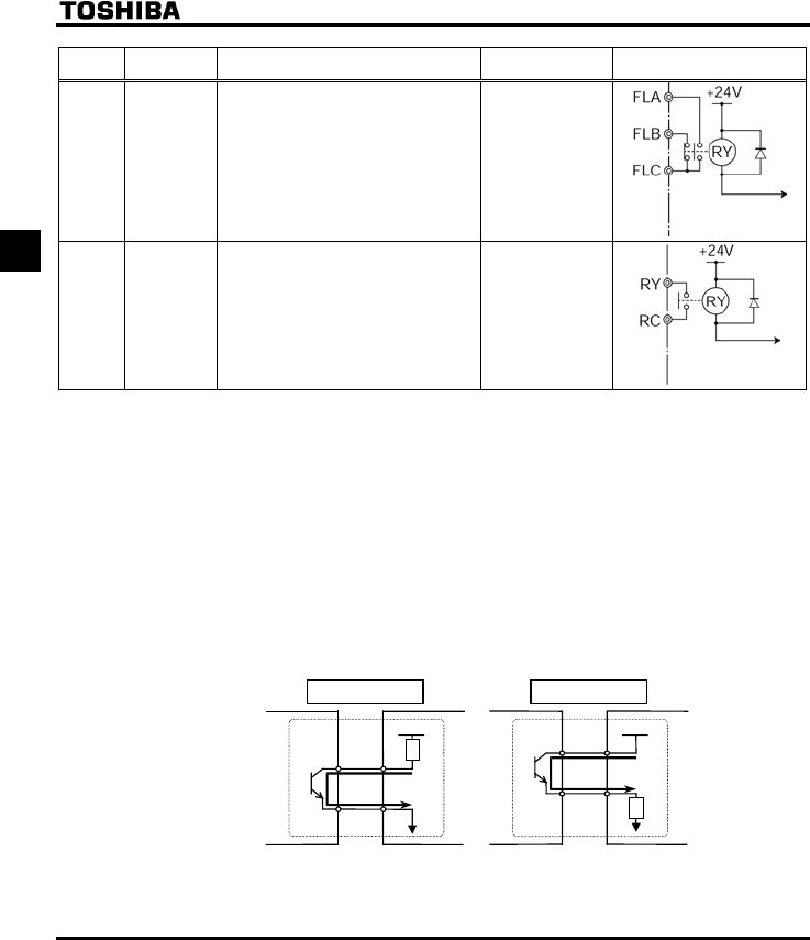
E6581381
B-8
2
Terminal
symbol Input/output Function Electrical
specifications Inverter internal circuits
FLA
FLB
FLC
Output
Multifunction programmable relay contact
output.
Detects the operation of the inverter's
protection function.
Contact across FLA-FLC is closed and FLB-
FLC is opened during protection function
operation.
250Vac-1A
(cosφ=1)
: at resistance load
30Vdc-0.5A
250Vac-0.5A
(cosφ=0.4)
RY
RC Output
Multifunction programmable relay contact
output.
Standard default settings detect and
output low-speed signal output
frequencies.
Multifunction output terminals to which two
different functions can be assigned.
250Vac-1A
(cosφ=1)
: at resistance load
30Vdc-0.5A
250Vac-0.5A
(cosφ=0.4)
■SINK (Negative) logic/SOURCE (Positive) logic (When the
inverter's internal power supply is used)
Current flowing out turns control input terminals on. These are called sink logic terminals.
The general used method in Europe is source logic in which current flowing into the input terminal turns it
on.
Sink logic is sometimes referred to as negative logic, and source logic is referred to as positive logic.
Each logic is supplied with electricity from either the inverter's internal power supply or an external power
supply, and its connections vary depending on the power supply used.
<Examples of connections when the inverter's internal power supply is used>
Source (Positive) logic
Inverter
P24
F
Programmable
controller
Common
Output
Input
24VDC
Sink (Negative) logic
F
CC
Common
Output
Input
24VDC
Inverter
Programmable
controller
Slide switch SW4:SINK Slide switch SW4:SOURCE
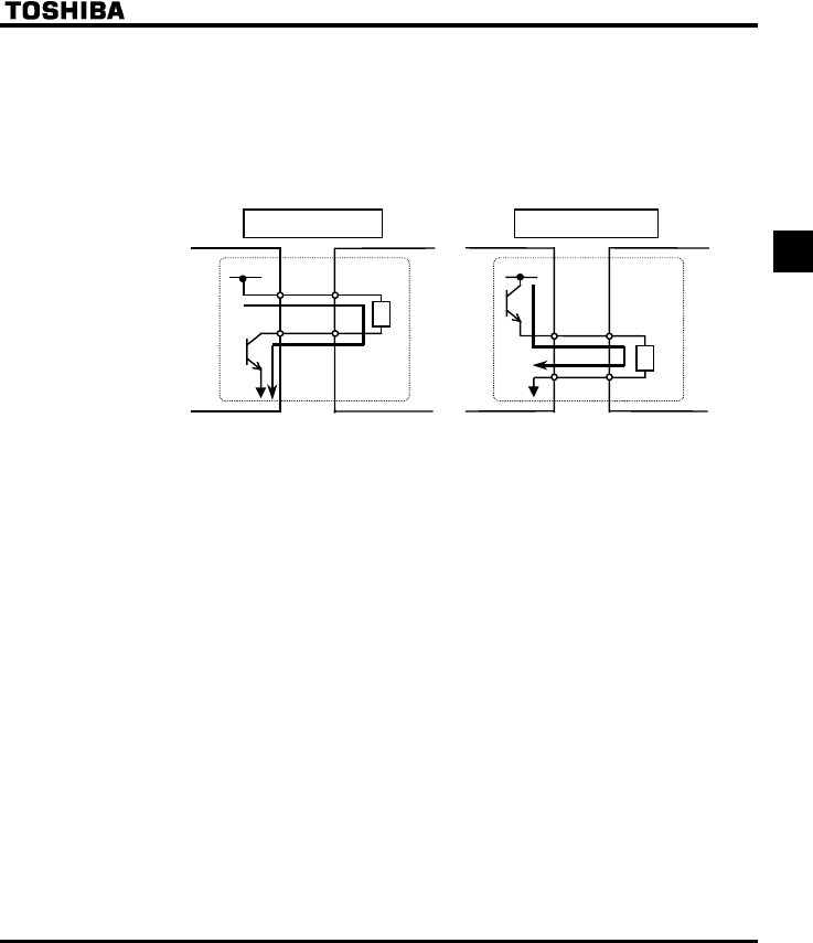
E6581381
B-9
2
■SINK (Negative) logic/SOURCE (Positive) logic (When an external power supply
is used)
The PLC terminal is used to connect to an external power supply or to insulate a terminal from other input
or output terminals. As for input terminals, turn the SW4 slide switch to the PLC position.
<Examples of connections when an external power supply is used>
Source (Positive) logic
Inverter
PLC
F
Programmable
controller
Common
Output
Input
24VDC
Sink (Negative) logic
F
Output
Input
24VDC
Inverter
Programmable
controller
Slide switch SW4:PLC Slide switch SW4:PLC
PLC
Common
■Selecting the functions of the VIA terminals between analog input and contact
input
The functions of the VIA terminal can be selected between analog input and contact input by changing
parameter settings (H). (Factory default setting: Analog input)
When using these terminals as contact input terminals in a sink logic circuit, be sure to insert a resistor
between the P24 and VIA terminals. (Recommended resistance: 4.7KΩ-1/2W)
When using the VIA terminal as a contact input terminal, be sure to turn the VIA (SW3) switch to the V
position. If no resistor is inserted or the VIA (SW3) slide switch is not turned to the V position, contact input
will be left always ON, which is very dangerous.
Switch between analog input and contact input before connecting the terminals to the control circuit
terminals. Otherwise the inverter or devices connected to it may be damaged.

E6581381
B-10
2
+The figure on the right shows an example of the
connection of input terminals VIA when there is used
as contact input terminals. This example illustrates
the connection when the inverter is used in sink
(Negative) logic mode.
■Logic switching/Voltage-current output switching (slide switch)
(1) Logic switching
Use SW4 to switch between logics.
Switch between logics before wiring to the inverter and without supplying power. If switching between
sink, source and PLC is done when power is turned on after switching or when the inverter is supplied
with power, the inverter might become damaged. Confirm it before supplying power.
(2) Voltage-current output switching
Use the FM (SW2) switch to switch between voltage output and current output.
Switch the FM terminal's voltage-current output before wiring to inverter or without supplying power.
Factory default settings of slide switches
SW4 : SINK (Negative) side (WN type)
SOURCE (Positive) side (WP type)
FM (SW2): V side
VIA (SW3): V side
E6581381
C-1
3
3. Operations
Danger
Prohibited
•Do not touch inverter terminals when electrical power is going to the inverter even if the motor is
stopped.
Touching the inverter terminals while power is connected to it may result in electric shock.
•Do not touch switches when the hands are wet and do not try to clean the inverter with a damp cloth.
Such practices may result in electric shock.
•Do not go near the motor in alarm-stop status when the retry function is selected.
The motor may suddenly restart and that could result in injury.
Take measures for safety, e.g. attaching a cover to the motor, against accidents when the motor
unexpectedly restarts.
Mandatory
•Turn power on only after attaching the front cover or closing door if enclosed in a cabinet.
If power is turned on without the front cover attached or closing door if enclosed in a cabinet, that may
result in electric shock or other injury.
•If the inverter begins to emit smoke or an unusual odor, or unusual sounds, immediately turn power off.
If the equipment is continued in operation in such a state, the result may be fire. Call your local sales
agency for repairs.
•Always turn power off if the inverter is not used for long periods of time.
•Turn input power on after attaching the front cover.
When enclosed inside a cabinet and using with the front cover removed, always close the cabinet
doors first and then turn power on. If the power is turned on with the front cover or the cabinet doors
open, it may result in electric shock.
•Make sure that operation signals are off before resetting the inverter after malfunction.
If the inverter is reset before turning off the operating signal, the motor may restart suddenly causing
injury.
Warning
Contact
prohibited
•Do not touch heat radiating fins or discharge resistors.
These device are hot, and you'll get burned if you touch them.
Prohibited
•Observe all permissible operating ranges of motors and mechanical equipment. (Refer to the motor's
instruction manual.)
Not observing these ranges may result in injury.
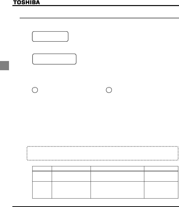
E6581381
C-2
3
3.1 Simplified Operation of the VF-FS1
The procedures for setting operation frequency and the methods of operation can be selected from the following.
Start / Stop :(1) Run and stop from the operation panel
(2) Run and stop using external signals to the terminal
board
(3) Run and stop through serial communication
Setting the frequency :(1) Setting using the operation panel
(2) Setting using external signals to the terminal board
(0-10Vdc, 4-20mAdc)
(3) Setting through serial communication
(4) Setting using external contact up/down
Local mode and Remote mode
Local mode : When Local mode selected by key, start and stop, and frequency setting are
effective only by operation panel keys.
The LOC/REM key lamp is lit while Local mode selected.
Remote mode : Start and stop, and frequency setting follow the selection of EOQF(Command
mode),or HOQF(Frequency setting mode).
*1 At default setting, the switching between Local mode and Remote mode is effective. When prohibiting this
function, refer to the chapter 6.20.1.
*2 At default setting, when switched from remote of start or stop and running frequency at Remote mode are
shifted to Local mode. When changing from Local mode to Remote mode, the inverter can start in case of
running mode selection at remote side. In case of prohibiting this function. ⇒ See section 6.10.
*3 The status of Local/Remote mode is memoried when power off.
Remote mode selection, use the basic parameters EOQF (Command
mode selection), HOQF (Frequency setting mode selection 1).
Title Function Adjustment range Default setting
EOQF Command mode selection
0: Terminal board
1: Panel
2:Serial communication
0
HOQF Frequency setting mode
selection 1
1: VIA
2: VIB
3: Operation panel
4: Serial communication
5: External contact up/down
1
* See 5.3 for EOQF,HOQF.
LOC
REM
LOC
REM
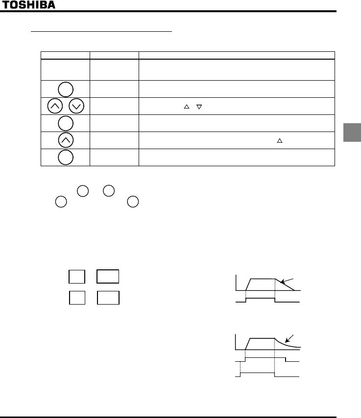
E6581381
C-3
3
3.1.1 How to start and stop
■Example of a EOQF setting procedure
Key operated LED display Operation
Displays the operation frequency (operation stopped).
(When standard monitor display selection H= [Operation
frequency])
CWH Displays the first basic parameter [Wizard function (CWH)].
EOQF Press either the or key to select “EOQF”.
Press ENT key to display the parameter setting. (Default setting:).
Change the parameter to (panel) by pressing the key.
⇔EOQF Press the ENT key to save the changed parameter. EOQF and the
parameter set value are displayed alternately.
(1) Start and stop using the operation panel keys (EOQF=)
Use the and keys on the operation panel to start and stop the motor.
: Motor starts. : Motor stops.
+To switch between forward run and reverse run from the control panel, the parameter HT
(forward/reverse run selection) needs to be set to or .
(2) RUN/STOP by means of an external signal to the terminal board (EOQF=):
Sink (Negative) logic
Use external signals to the inverter terminal board to start and stop the motor.
Short and terminals: run forward Frequency
ON
OFF
F-CC
Slow down
and stop
F
Open and terminals: slow down and stop
CC
FCC
(3) Coast stop
The standard default setting is for slowdown stop. To
make a coast stop, assign a "1(ST)" terminal function
to an idle terminal using the programmable terminal
function.
Change to H=.
For coast stop, open the ST-CC when stopping the
motor in the state described at left.The monitor on the
inverter at this time will display QHH.
Motor
speed
ON
OFF
ON
OFF
F-CC
ST-CC
Coast stop
MODE
ENT
ENT
STOP
RUN
RUN STOP
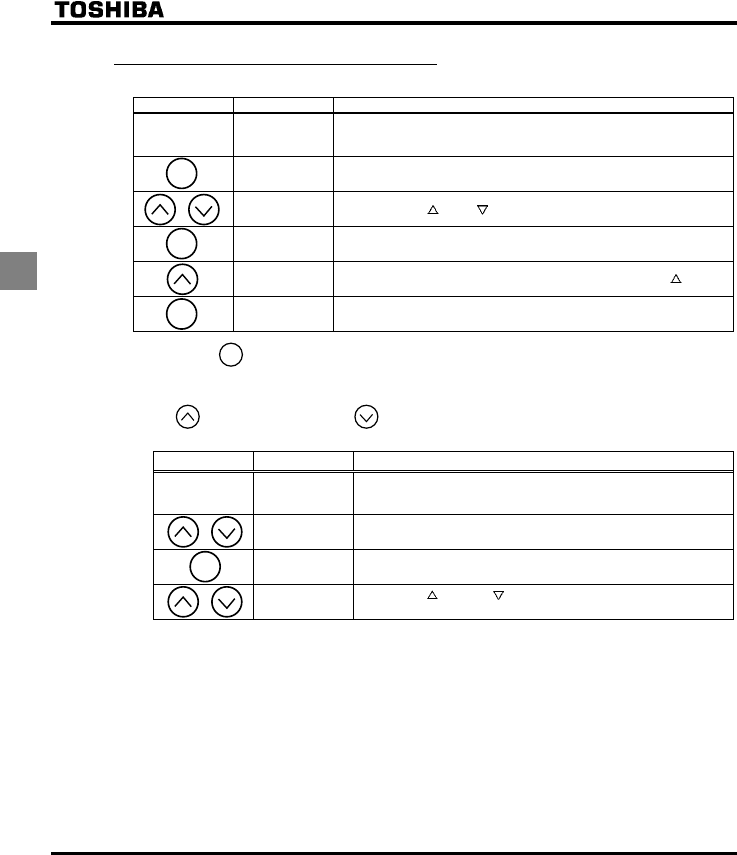
E6581381
C-4
3
3.1.2 How to set the frequency
■Example of a HOQF setting procedure
Key operated LED display Operation
Displays the operation frequency (operation stopped).
(When standard monitor display selection H= [Operation
frequency])
CWH Displays the first basic parameter [Wizard function (CWH)].
HOQF Press either the key or key to select “HOQF”.
Press ENT key to display the parameter setting. (Default setting: ).
Change the parameter to (Operation panel) by pressing the key.
⇔HOQF Press the ENT key to save the changed parameter. HOQF and the
parameter set value are displayed alternately.
* Pressing the key twice returns the display to standard monitor mode (displaying operation frequency).
(1) Setting the frequency using the operation panel (HOQF=)
Set the frequency with the operation panel..
: Moves the frequency up : Moves the frequency down
■Example of operating a run from the panel
Key operated LED display Operation
Displays the operation frequency.
(When standard monitor display selection H= [Operation
frequency])
Set the operation frequency.
⇔HE Press the ENT key to save the operation frequency. HE and the
frequency are displayed alternately.
Pressing the key or the key will change the operation frequency
even during operation.
MODE
ENT
ENT
MODE
ENT
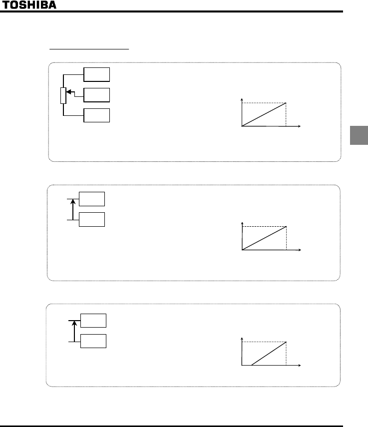
E6581381
C-5
3
(2) Setting the frequency using the operation panel (HOQF= or )
■Frequency setting
1) Setting the frequency using external potentiometer
: Setting frequency
using potentiometer
+Potentiometer
Setting frequency using the potentiometer (1-10kΩ, 1/4W)
⇒ For more detailed information on adjustments, see
section 6.5.
Frequency
60Hz
0
MIN MAX
* The input terminal VIA can be used in the same way.
HOQF=: VIA effective, HOQF=: VIB effective
⇒ For more details, see section 6.5.
PP
CC
V
IB
2) Setting the frequency using input voltage (0~10V)
+Voltage signal
Setting frequency using voltage signals (0∼10V).
⇒ For more detailed information on adjustments, see
section6.5.
Frequency
60Hz
0
0Vdc 10Vdc
* The input terminal VIB can be used in the same way.
HOQF=: VIA effective, HOQF=: VIB effective
⇒ For more details, see section 6.5.
Note: Be sure to turn the VIA (SW3) slide switch to the V (voltage) position.
CC
V
I
A
+
-
: Voltage signal 0-10Vdc
3) Setting the frequency using current input (4~20mA)
+Current Signal
Current signal Setting frequency using current signals (4~20mA).
⇒ For more detailed information on adjustments, see section 6.5.
Frequency
60Hz
04mAdc 20mAdc
* Setting of parameters also allow 0-20mAdc.
Note: Be sure to turn the VIA (SW3) slide switch to the I (current) position.
CC
V
I
A
+
-
: Current signal 4-20mAdc
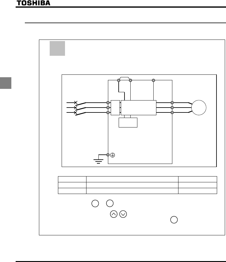
E6581381
C-6
3
3.2 How to operate the VF-FS1
Overview of how to operate the inverter with simple examples.
Remote mode selection,
Setting the operation frequency using the operation panel and
running and stopping using the operation panel.
(1) Wiring
(2) Parameter setting
Title Function Setting value
EOQF Command mode selection 1
HOQF Frequency setting mode selection 1 3
(3) Operation
Run/stop: Press the and keys on the panel.
Frequency setting: Set with the keys on the operation panel.
To store the set frequencies in memory, press the key.
HEand the set frequency will flash on and off alternately.
Control
circuit
Motor
IM
R/L1
S/L2
T/L3
U/T1
V/T2
W/T3
PC/-PA/+
Power circuit
MCCB
Noise
filter
*
Ex.1
STOP
RUN
ENT
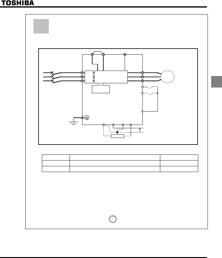
E6581381
C-7
3
Remote mode selection,
Operation frequency setting, running and stopping using external
signals.
(1) Wiring
(2) Parameter setting
Title Function Setting value
EOQF Command mode selection 0
HOQF Frequency setting mode selection 1 1or2
(3) Operation
Run/stop: ON/OFF input to F-CC, R-CC. (Set SW4 to Sink logic)
Frequency setting: VIA and VIB: 0-10Vdc (External potentiometer)
VIA: Input 4-20mAdc.
Use the VIA (SW3) slide switch to switch between voltage and current to the VIA terminal.
Voltage input: V side
Current input: I side
+Please turn off the lamp by pressing the key when the LOC/REM key lamp is lit.
Control
circuit
Motor
IM
F
R/L1
S/L2
T/L3
U/T1
V/T2
W/T3
Run forward signal
R
PC/-
PA/+
Power circuit
Run backward signal
MCCB
CC Common
CC VIB
VIA PP
Voltage signal: 0
∼
10V, Current signal: 4∼20mA
External potentiometer
(Otherwise, input voltage signal (0~10V) between the terminals VIA-CC.)
Noise
filter
*
Ex.2
LOC
REM
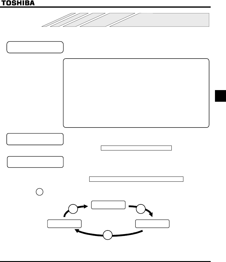
E6581381
D-1
4
4. Basic VF-FS1 operations
The VF-FS1 has the following three monitor modes.
Standard monitor mode : The standard inverter mode. This mode is enabled when
inverter power goes on.
This mode is for monitoring the output frequency and setting the frequency
designated value. In it is also displayed information about status alarms during
running and trips.
•Setting frequency designated values ⇒ See section 3.1.2
•Status alarm
If there is an error in the inverter, the alarm signal and the frequency will flash
alternately in the LED display.
E: When a current flows at or higher than the overcurrent stall level.
R: When a voltage is generated at or higher than the over voltage stall
level.
N: When a load reaches 50% or higher of the overload trip value.
J: When the temperature reaches the overheating protection alarm level.
Setting monitor mode : The mode for setting inverter parameters.
How to set parameters ⇒ See section 4.2.
Status monitor mode : The mode for monitoring all inverter status.
Allows monitoring of set frequencies, output current/voltage and terminal
information.
For more on how to use the monitor ⇒ See section 8.1.
Pressing the key
will move the inverter through each of the modes.
Standard monitor
mode
Status monitor
mode
Setting monitor
mode
MODE MODE
MODE
MODE
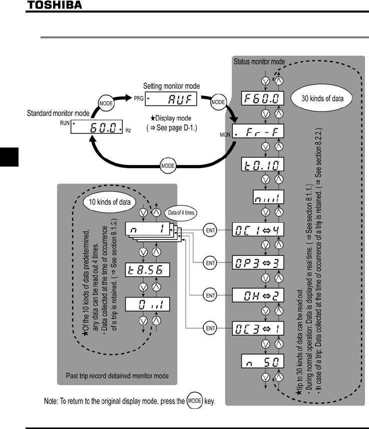
E6581381
D-2
4
4.1 Flow of status monitor mode
Flow of monitor as following

E6581381
D-3
4
4.2 How to set parameters
The standard default parameters are programmed before the unit is shipped from the factory. Parameters can be
divided into 5 major categories. Select the parameter to be changed or to be searched and retrieved.
Basic parameters : The basic parameters that must be programmed
before the first use. ⇒ See section 4.2.1.
Extended parameters : The parameters for detailed and special setting.
⇒ See section 4.2.2.
User parameters
(automatic edit function)
: Indicates parameters that are different from the
standard default setting parameters. Use them to
check after setting and to change setting.
(Parameter title: I4W). ⇒ See section 4.2.3.
: The wizard function refers to the special function of
calling up ten frequently used parameters.
You can set up the inverter easily by simply setting the
parameters in one after another. (Parameter name:
CWH). ⇒ See section 4.2.4.
: This parameter has the function of displaying, in
reverse chronological order, the five parameters that
were changed last. This function comes in very handy
when you adjust the inverter repeatedly using the
same parameter. (Parameter name: CWJ).
⇒ See section 4.2.5.
* Adjustment range of parameters
JK: An attempt has been made to assign a value that is higher than the programmable range. Or, as
a result of changing other parameters, the programmed value of the parameter that is now
selected exceeds the upper limit.
NQ: An attempt has been made to assign a value that is lower than the programmable range. Or, as a
result of changing other parameters, the programmed value of the parameter that is now selected
exceeds the lower limit.
If the above alarm is flashing on and off, no setting can be done of values that are equal to or greater
than JK or equal to or lower than NQ.
Wizard function
History parameter
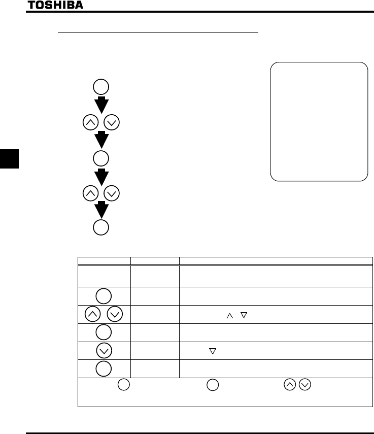
E6581381
D-4
4
4.2.1 How to set the basic parameters
All of the basic parameters can be set by the same step procedures.
Switches to the setting monitor mode.
* Parameters were
factory-set by default
before shipment.
* Select the parameter to
be changed from "Table
of parameters".
* If there is something
that you do not
understand during the
operation, press the
MODE key to return to
the indication.
⇒ See section 11.2 for
basic parameters.
Reads the programmed parameter
setting.
Saves the changed value of the
parameter setting.
Selects parameter to be changed.
Changes the parameter setting.
[Steps in key entry for basic parameters]
■
Example of setting procedure (Changing the maximum frequency from 80Hz to 60Hz).
Key operated LED display Operation
Displays the operation frequency (operation stopped).
(When standard monitor display selection H= [Operation
frequency])
CWH The first basic parameter “CWH” (Wizard function) is displayed.
HJ Press either the or key to select “HJ”.
Pressing the ENT key reads the maximum frequency.
Press the key to change the maximum frequency to 60Hz.
⇔HJ Press the ENT key to save the maximum frequency. HJ and the
frequency are displayed alternately.
After this, →Displays the same
programmed
parameter.
→Switches to the
display in the
status monitor
mode.
→Displays names
of other
parameters.
ENT
MODE
ENT
ENT
MODE
MODE
ENT
ENT
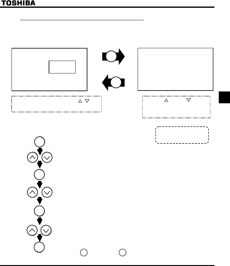
E6581381
D-5
4
4.2.2 How to set extended parameters
The VF-FS1 has extended parameters to allow you to make full use of its functions.
All extended parameters are expressed with H and three digits.
Basic parameters
H H∼H
Press the MODE key once and use the / key
to select H from the basic parameters.
Press the key or the key to
change the set value. Pressing
the ENT key allows the reading of
parameter setting.
MODE
ENT
[Steps in key entry for extended parameters]
: Switches to the setting monitor mode.(Displays CWH)
: Selects "H" from basic parameters.
: The first extended parameter “HK” (Low-speed signal output frequency) is displayed.
: Selects the extended parameter whose setting needs to be changed.
: Reads the programmed parameter setting.
: Changes the parameter setting.
Saves the changed value of the extended parameter setting.
Pressing the key instead of the key moves back to the previous status.
MODE
ENT
ENT
ENT
⇒ See section 11.3 for
extended parameters.
MODE
ENT
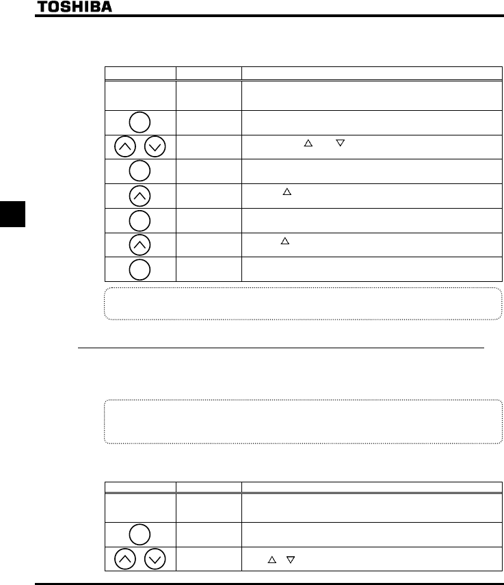
E6581381
D-6
4
■Example of parameter setting
Steps in setting are as follows
(Example of Auto-restart control selectionH from 0 to 1.)
Key operated LED display Operation
.
Displays the operation frequency (operation stopped).
(When standard monitor display selection H= [Operation
frequency])
CWH The first basic parameter “CWH” (Wizard function) is displayed.
H Press either the or the to change to the parameter group
H.
H Press the ENT key to display the first extended parameter H.
H Press the key to change to the auto-restarte control selection
H.
Pressing the ENT key allows the reading of parameter setting.
Press the key to change the auto-restarte control selection from
to .
⇔H Pressing the ENT key alternately flashes on and off the parameter
and changed value and allows the save of those values.
If there is anything you do not understand during this operation, press the MODE key several times to
start over from the step of CWH display.
4.2.3 Search and resetting of changed parameters (I4W)
Automatically searches for only those parameters that are programmed with values different from the
standard default setting and displays them in the user parameter group I4W. Parameter setting can also be
changed within this group.
Notes on operation
•If you reset a parameter to its factory default, the parameter will no longer appear in I4W.
•HO, HH are not appeared, if the value of these parameters are changed.
■How to search and reprogram parameters
The operations of search and resetting of parameters are as follows.
Key operated LED display Operation
Displays the operation frequency (operation stopped).
(When standard monitor display selection H= [Operation
frequency])
CWH The first basic parameter “CWH” (Wizard function) is displayed.
ITW Press or key to select I4W.
MODE
ENT
ENT
ENT
MODE
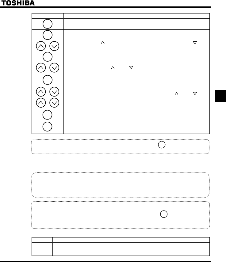
E6581381
D-7
4
Key operated LED display Operation
W Press the ENT key to enable the user parameter automatic edit
function.
or
WH
(WT)
↓
CEE
Searches for parameters that are different in value from the standard
default setting and displays those parameters. Press the ENT key or
the key to change the parameter displayed. (Pressing the key
moves the search in the reverse direction).
Press the ENT key to display the set value.
Press the key and key to change set value.
⇔CEE
Press the ENT key to save the changed value. The parameter name
and the programmed value will flash on and off alternately.
After the change has been saved, “W“ is displayed.
( ) WH
(WT)
Use the same steps as those given above to display parameters that
you want to search for or change setting with the key and key.
( ) ITW When IT. W appears again, the search is ended.
ITW
↓
HTH
↓
A search can be canceled by pressing the MODE key. Press the
MODE key once while the search is underway to return to the display
of parameter setting mode.
After that you can press the MODE key to return to the status
monitor mode or the standard monitor mode (display of operation
frequency).
If there is anything you do not understand during this operation, press the key several times to
start over from the step of CWHdisplay.
4.2.4 Setting a parameter, using the wizard function (CWH)
Wizard function (CWH):
The wizard function refers to the special function of calling up ten frequently used parameters.
You can set up the inverter easily by simply setting the parameters in one after another.
Notes on operation
• If there is anything you do not understand during this operation, press the key several times to
start over from the step of CWH display.
JGCF or GPF is affixed respectively to the first or last parameter.
[Parameter setting]
Title Function Adjustment range Default setting
CWH Wizard function
The wizard function refers to the
special function of calling up ten
frequently used parameters.
-
MODE
ENT
ENT
ENT
ENT
MODE
MODE
MODE
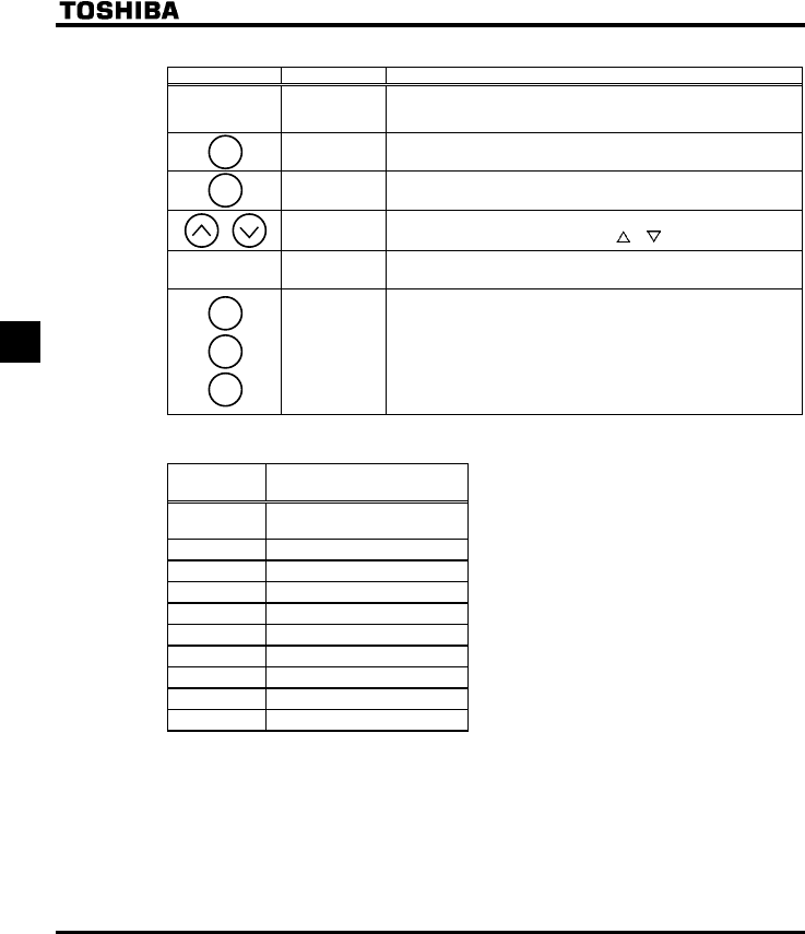
E6581381
D-8
4
■How to use the wizard function
Key operated LED display Operation
Displays the operation frequency (operation stopped).
(When standard monitor display selection H= [Operation
frequency])
CWH The first basic parameter “CWH” (Wizard function) is displayed.
CW Press the ENT key to confirm your choice. The first parameter in the
purpose-specific wizard parameter group is displayed. (See Table below)
( ) **** After moving to the purpose-specific wizard parameter group, change the
setting of each parameter by pressing the or key and the ENT key.
GPF GPF is dialyzed on completion of the setting of the wizard parameter
group.
Parameter
display
↓
CWH
↓
HTH
↓
Press the MODE key to exit the wizard parameter group.
By pressing the MODE key, you can return to the default monitoring mode
(display of operation frequency).
■ How Parameters of Quick setting wizard
Title Function
CW Automatic
acceleration/deceleration
CEE Acceleration time 1
FGE Deceleration time 1
NN Lower limit frequency
WN Upper limit frequency
VJT Motor thermal protection
HO Meter adjustment
RV V/F control mode selection
XN Base frequency 1
XNX Base frequency voltage 1
MODE
ENT
MODE
MODE
MODE
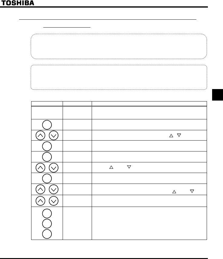
E6581381
D-9
4
4.2.5 Searching for a history of changes, using the history
function (CWJ)
History function (CWJ):
Automatically searches for 5 latest parameters that are programmed with values different from the
standard default setting and displays them in the CWJ. Parameter setting can also be changed
within this group CWJ.
Notes on operation
•If no history information is stored, this parameter is skipped and the next parameter “CW” is
displayed.
•JGCF and GPF are added respectively to the first and last parameters in a history of changes.
■How to use the history function
Key operated LED display Operation
Displays the operation frequency (operation stopped).
(When standard monitor display selection H= [Operation
frequency])
CWH The first basic parameter “CWH” (Wizard function) is displayed.
CWJ Select the History function (CWJ) by pressing the or key.
CEE The parameter that was set or changed last is displayed.
Press the ENT key to display the set value.
Press the key and key to change set value.
⇔CEE Press the ENT key to save the changed value. The parameter name
and the programmed value will flash on and off alternately.
( ) **** Use the same steps as those given above to display parameters that
you want to search for or change setting with the key and key.
( ) JGCF
(GPF)
JGCF: First historic record
GPF: Last historic record
Parameter
display
↓
CWH
↓
HTH
↓
Press the MODE key to return to the parameter setting mode
“CWH.”
After that you can press the MODE key to return to the status
monitor mode or the standard monitor mode (display of operation
frequency).
Note: Parameter H (Prohibition of change of parameter settings) is not displayed in this “CWJ”.
MODE
ENT
ENT
ENT
MODE
MODE
MODE
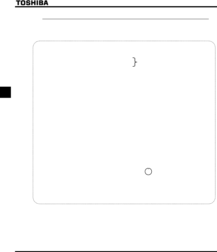
E6581381
D-10
4
4.2.6 Parameters that cannot be changed while running
For safety reasons, the following parameters have been set up so that they cannot be reprogrammed while
the inverter is running. Stop operation (“” or “QHH” is displayed) before changing parameter settings.
[Basic parameters]
CW : Automatic acceleration/deceleration
CW : Parameter setting macro function
EOQF : Command mode selection
HOQF : Frequency setting mode selection 1
V[R : Default setting
HJ : Maximum frequency
XN : Base frequency 1
XNX : Base frequency voltage1
RV : V/F control mode selection 1
[Extended parameters]
H∼H : Input terminal selection parameters
H∼H : Output terminal selection parameters
H : Base frequency 2
H : Base frequency voltage 2
H∼H : Protection parameters
H : Carrier frequency control mode selection
H : Auto-tuning
H∼H : Motor constant parameters
H∼H : Motor control parameters
H : Stall prevention level 1
H : Emergency stop selection
H : Output phase failure detection mode selection
H : Input phase failure detection mode selection
H : Detection of output short-circuit during start-up selection
H : Over-voltage stall protection level
H : Under voltage trip/alarm selection
H : Prohibition of panel local/remote operation ( key)
H∼H : PM motor parameters
The setting of any parameter other than the above can be changed even during operation.
Keep in mind, however, that when the parameter H (prohibition of change of parameter settings) is set to
(prohibited), no parameters can be set or changed.
Set H, and they can be changed while
the inverter is running.
LOC
REM
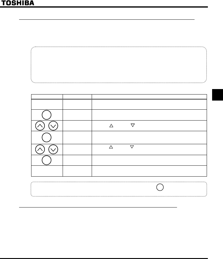
E6581381
D-11
4
4.2.7 Returning all parameters to standard default setting
Setting the standard default setting parameter V[R=, all parameters can be returned to the those factory
default settings.
⇒ For more details on the standard default setting parameter V[R, see section 5.5.
Notes on operation
•We recommend that before this operation you write down on paper the values of those parameters,
because when setting V[R=, all parameters with changed values will be returned to standard
factory default setting.
•Note that HO, HOUN, H, HH and H will not be reset to their factory
default settings.
■Steps for returning all parameters to standard default setting
Key operated LED display Operation
Displays the operation frequency (perform during operation stopped).
CWH The first basic parameter “CWH” (Wizard function) is displayed.
V[R Press the key or the key to change to V[R.
Pressing the ENT key displays the programmed parameters. (V[R
will always display "(zero)" on the right, the previous setting on the
left.)
Press the key or the key to change the set value.
To return to standard factory default setting, change to "".
KPKV Pressing the ENT key displays "KPKV" while returning all
parameters to factory default setting.
The monitor returns to the display of setup parameters.
If there is anything you do not understand during this operation, press the key several times to
start over from the step of CWH display.
4.2.8 How to save/load the user setting parameters
The current settings of all parameters can be stored (saved) in memory at a time by setting the standard
setting mode selection parameter V[R to . Also, all parameter settings stored in memory can be restored
(loaded) by setting parameter V[R to . This means that you can use this parameter (V[R= and ) as
the parameter for your own initial settings (default settings).
ENT
MODE
ENT
MODE
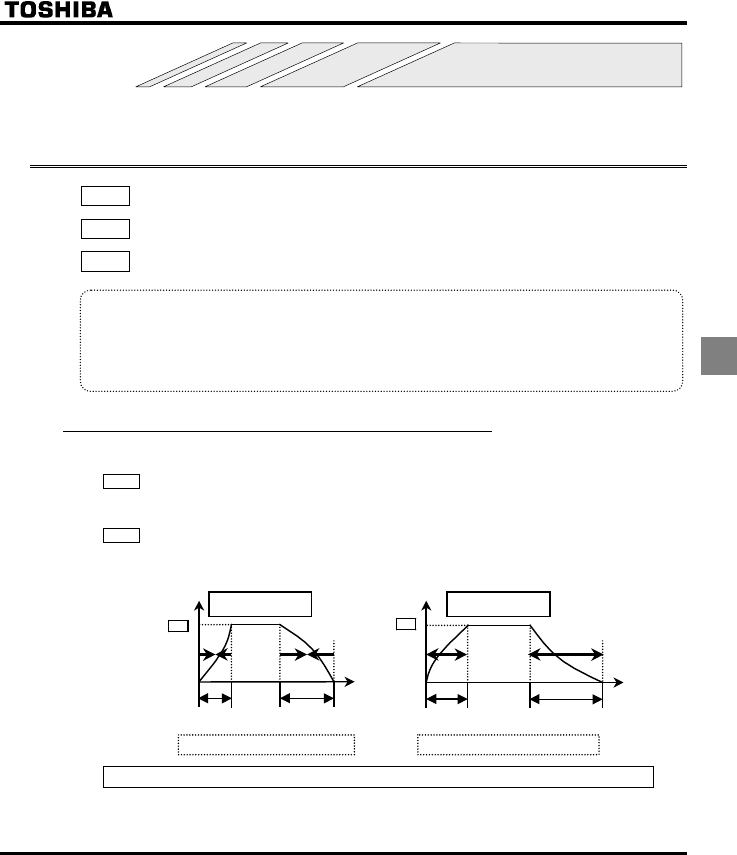
E6581381
E-1
5
5. Basic parameters
Before you operate the inverter, the parameters that you must first program are the basic parameters.
5.1 Setting acceleration/deceleration time
CW :Automatic acceleration/deceleration
CEE :Acceleration time 1
FGE :Deceleration time 1
•Function
1) For acceleration time 1 CEE programs the time that it takes for the inverter output frequency to go from
0Hz to maximum frequency HJ.
2) For deceleration time 1 FGE programs the time that it takes for the inverter output frequency to got
from maximum frequency HJ to 0Hz.
5.1.1 Automatic acceleration/deceleration
This automatically adjusts acceleration and deceleration time in line with load size.
CW =
* Adjusts the acceleration/deceleration time automatically within the range of 1/8 to 8 times as long as the
time set with the CEE or FGE, depending on the current rating of the inverter.
CW =
* Automatically adjusts speed during acceleration only. During deceleration, speed is not adjusted
automatically but reduced at the rate set with FGE.
Output
frequency (Hz)
Deceleration
time
Acceleration
time
HJ
When load is small
Time
[sec]
0
Shorten acceleration/deceleration time
Deceleration
time
Acceleration
time
HJ
When load is large
Output
frequency (Hz)
Time
[sec]
0
Lengthen acceleration/deceleration time
Set CW (automatic acceleration/deceleration) to or .
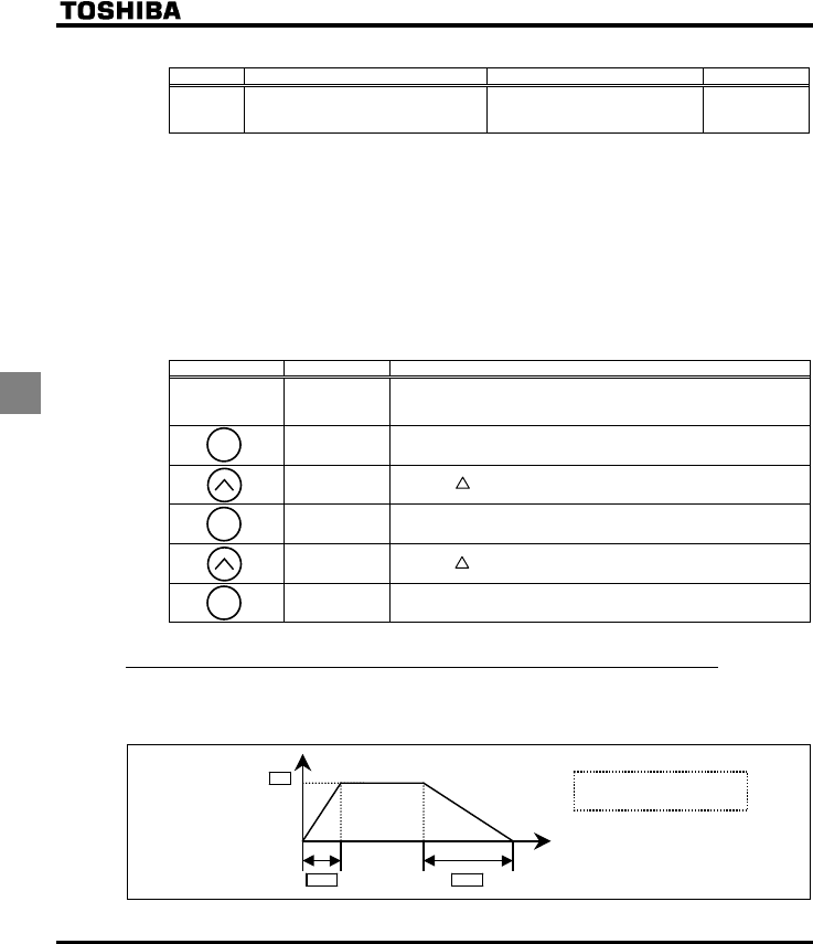
E6581381
E-2
5
[Parameter setting]
Title Function Adjustment range Default setting
CW Automatic acceleration/deceleration
0: Disabled (manual)
1: Automatic
2: Automatic (only at acceleration)
0
+When automatically setting acceleration/deceleration time, always change the acceleration/deceleration
time so that it conforms to the load. The acceleration/deceleration time changes constantly with load
fluctuations. For inverters that requires a fixed acceleration/deceleration time, use the manual settings
(CEE, FGE).
+Setting acceleration/deceleration time (CEE,FGE) in conformance with mean load allows optimum
setting that conforms to further changes in load.
+Use this parameter after actually connecting the motor.
+When the inverter is used with a load that fluctuates considerably, it may fail to adjust the acceleration or
deceleration time in time, and therefore may be tripped.
■Methods of setting automatic acceleration/deceleration
Key operated LED display Operation
Displays the operation frequency.
(When standard monitor display selection H is set to
[Operation frequency])
CWH The first basic parameter “CWH” (Wizard function) is displayed.
CWK Press the key to change the parameter to CWK.
Pressing the ENT key allows the reading of parameter setting.
Press the key to change the parameter to or .
⇔CW Press the ENT key to save the changed parameter. CW and the
parameter are displayed alternately.
5.1.2 Manually setting acceleration/deceleration time
Set acceleration time from 0 (Hz) operation frequency to maximum frequency HJ and deceleration time as
the time when operation frequency goes from maximum frequency HJ to 0 (Hz).
Output frequency (Hz)
FGE
CEE
HJ
Time [sec]
O
CW = (Manual)
MODE
ENT
ENT

E6581381
E-3
5
[Parameter setting]
Title Function Adjustment range Default setting
CEE Acceleration time 1 0.0-3200 sec. According to model
(⇒ See page K-14)
FGE Deceleration time 1 0.0-3200 sec. According to model
(⇒ See page K-14)
Note: When the acceleration/deceleration time is set at 0.0 seconds, the inverter speed increases or reduces
speed within 0.05 seconds.
+If the programmed value is shorter than the optimum acceleration/deceleration time determined by load
conditions, overcurrent stall or overvoltage stall function may make the acceleration/deceleration time
longer than the programmed time. If an even shorter acceleration/deceleration time is programmed, there
may be an overcurrent trip or overvoltage trip for inverter protection.
⇒ For further details, see section 13.1.
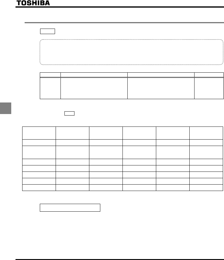
E6581381
E-4
5
5.2 Specifying an operation mode, using parameters
CW : Parameter setting macro function
•Function
Automatically programs all parameters (parameters described below) related to the functions by selecting
the inverter's operating method.
The major functions can be programmed simply.
[Parameter setting]
Title Function Adjustment range Default setting
CW Parameter setting macro function
0: Disabled
1: Coast stop
2: 3-wire operation
3: External input UP/DOWN setting
4: 4-20mA current input operation
0:
Note: When this parameter is invoked after it has been set, is always displayed (on the right side).
The number on the left side refers to the number specified previously.
Example
Automatically programmed functions and parameter set values
Relational
parameter
Default setting
value
1: Coast stop 2: 3-wire
operation
3: External input
UP/DOWN
setting
4: 4-20mA
current input
operation
EOF 0: Terminal board 0: Terminal board 0: Terminal board 0: Terminal board 0: Terminal board
HOF 1: VIA 1: VIA 1: VIA
5: UP/DOWN
from external
contact
1: VIA
H (Always) 1: ST 0: Disabled 1: ST 1: ST 1: ST
H (F) 2:F 2:F 2:F 2:F 2:F
H (R) 3:R 1:ST 49:HD 41:UP 6:S1
H (RES) 10: RES 10: RES 10: RES 42:DOWN 10: RES
H 0 (%) - - - 20 (%)
⇒ See K-14 for input terminal functions.
Disabled (CW=)
The parameter does nothing. Even if set to , CW will not return the setting you made to its factory
default.
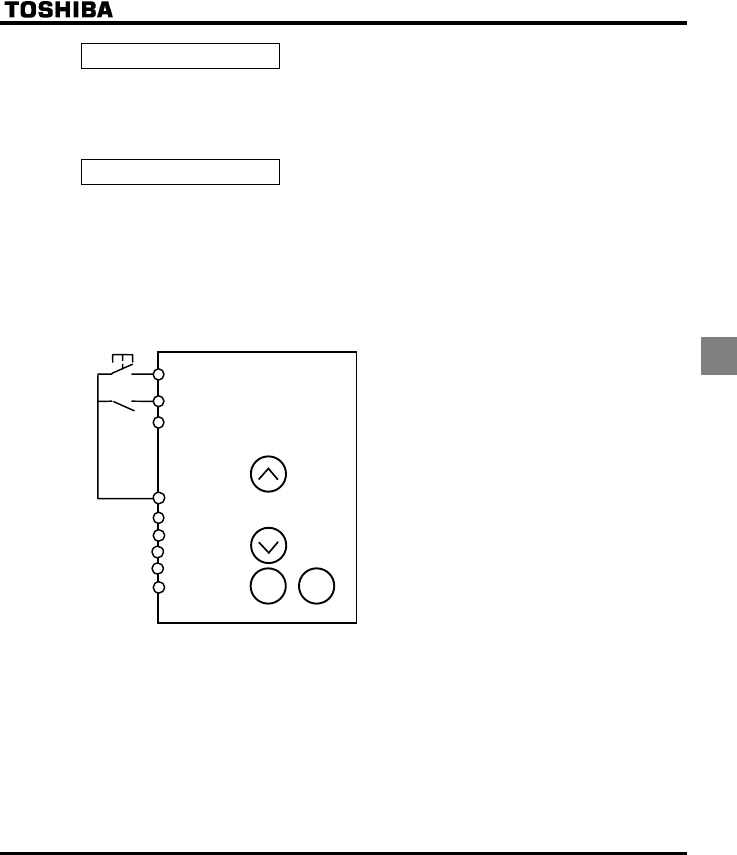
E6581381
E-5
5
Coast stop (CW=)
Setting for coast stopping. In sink logic mode, closing the circuit between the R and CC terminals places the
inverter in standby mode and opening the circuit places it in coast stop mode, because ST (standby signal)
is assigned to the R terminal.
⇒ See section 3.1.1 (3) and 6.3.1 for details.
3-wire operation (CW=)
Can be operated by a momentary push-button. HD (operation holding) is assigned to the terminal R. A self-
holding of operations is made in the inverter by connecting the stop switch (b-contact) to the R terminal and
connecting the running switch (a-contact) to the F terminal.
+Three-wire operation (one-touch operation)
You can carry out operation by simply pressing the ON/OFF button.
Standard connection diagram- Forward run
Selecting HD (operation holding) with the input
terminal selection parameter
Select HD (operation holding) using the input
terminal selection parameter, and turn HD on to
get the inverter ready for operation or turn HD
off to stop operation.
Parameter setting:
When parameter CWis set to , the following
parameters are set automatically.
H : (ST)
EOQF : (terminal board).
R terminal H : (operation holding).
Note 1 : Even if each terminal is ON, any command entered
through a terminal is ignored when power is turned
on (to prevent the load from starting to move
unexpectedly). Enable to turn the input terminal on
at power on.
Note 2 : When HD is OFF, any attempt to turn on F is
ignored.
Note 3 : Sending out a RUN signal during DC braking has
no effect in stopping DC braking.
F
R (HD)
RES
CC
PLC
PP
VI
A
VIB
CC STOPRUN
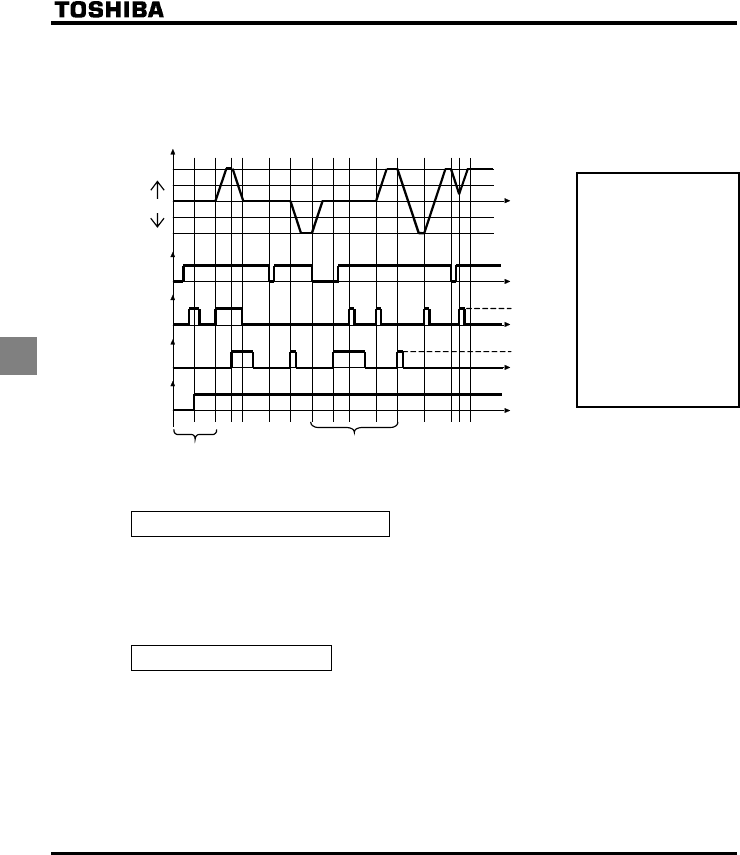
E6581381
E-6
5
In the case of reverse operation, the 3 wires operation is also possible as well as forward operation by assigning "R
(reverse function)" to the "RES" terminal.
External input UP/DOWN setting (CW=)
Allows setting of frequency with the input from an external contact. Can be applied to changes of
frequencies from several locations.
In case of cancelling the frequency UP/DOWN, it is necessary to assign "CLR (frequency UP/DOWN
cancellation from external contacts function)" to the "VIA" terminal separately.
⇒ See section 6.5.3 for details.
4-20 mA current input(CW=)
Used for setting frequencies with 4-20mAdc current input.
R
F
HD
Powered
on
Note 1
ON
OFF
ON
OFF
ON
OFF
ON
OFF
Output frequency
Forward run
Reverse run
0
Note 2,4
Operation
frequency
command
Operation
frequency
command
Note 4 :
When HD is OFF, any
attempt to turn on F or R is
ignored. When R is ON,
you cannot start operation
by turning on HD. Even
when both R and HD are
ON, you cannot start
operation by turning on F.
To start operation, turn off
F and R temporarily, then
turn them back on.
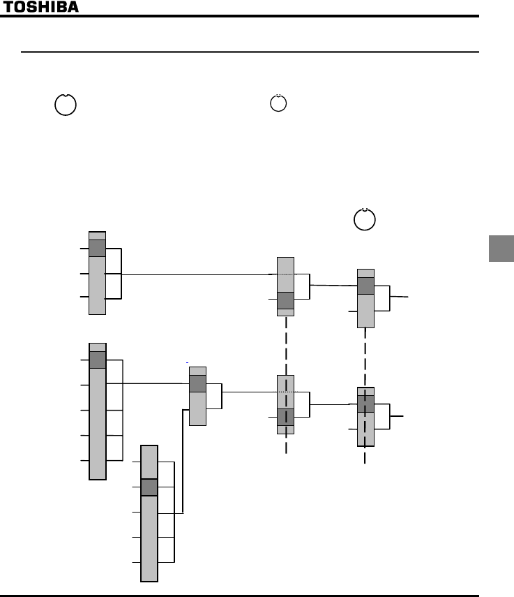
E6581381
E-7
5
5.3 Selection of operation mode
Local mode and Remote mode
Local mode : When Local mode selected by key, start and stop, and frequency setting are
effective only by operation panel keys.
The local lamp is lit while Local mode selected.
Remote mode : Start and stop, and frequency setting follow the selection of EOQF(Command
mode),or HOQF(Frequency setting mode).
Setting mode – Switching of commands and references
Key
Commands
EOQF
Terminal board
Ope
r
at
i
o
n
pa
n
e
l
Com. priorit
y
cancellation
Logic input* = CPCA (48)
Run / Forward
Run / Reverse
References
HOQF
VIA
Local/Remote
Logic input* = FCHG (38)
Internal
reference
Serial
communication
H
Operation panel
Serial
communication
UP/DOWN
VIB
Operation panel
Serial
communication
UP/DOWN
VIB
VIA
Serial
communication
Serial
communication
Operation
panel
Operation
panel
Frequency reference
H priority switch
LOC
REM
LOC
REM
LOC
REM
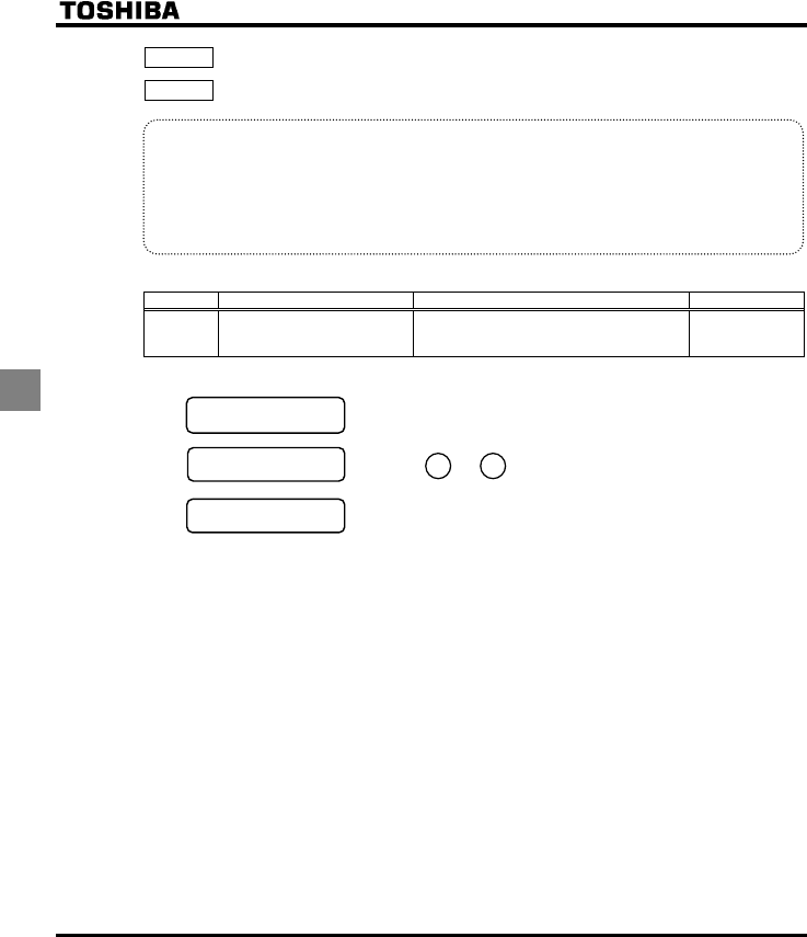
E6581381
E-8
5
EOQF : Command mode selection
HOQF : Frequency setting mode selection 1
•Function
Remote mode selection, these parameters are used to specify which input device (operation panel,
terminal board, serial communication) takes priority in entering an operation stop command or a frequency
setting command, VIA, VIB, operation panel, serial communication device, external contact up/down).
At Local mode selection, the start/stop operation and frequency setting by operation panel is prior with no
relation of EOQF/HOQFsetting.
<Command mode selection>
Title Function Adjustment range Default setting
EOQF Command mode selection
0: Terminal board
1: Operation panel
2: Serial communication
0
Programmed value
:Terminal board
operation ON and OFF of an external signal Runs and stops operation.
:Operation panel
operation Press the and keys on the operation panel to start and stop.
Serial communication
operation Run and stop through serial communication.
* There are two types of function: the function that conforms to commands selected by EOQF, and the function
that conforms only to commands from the terminal board.
⇒ See the table of input terminal function selection in Chapter 11.
* When priority is given to commands from a linked computer or terminal board, they have priority over the
setting of EOQF.
STOPRUN
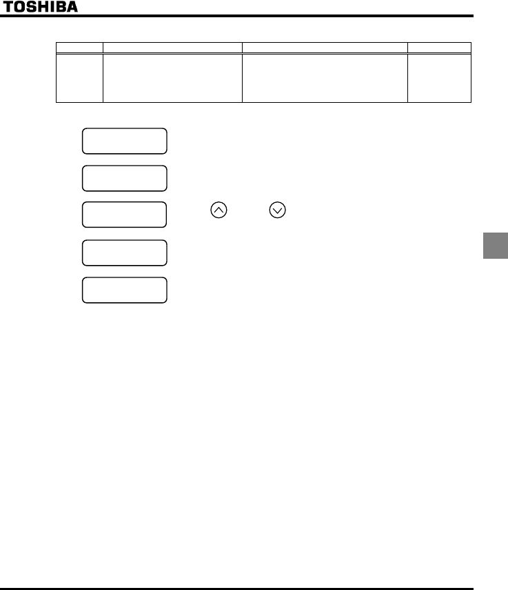
E6581381
E-9
5
<Frequency setting mode selection>
Title Function Adjustment range Default setting
HOQF Frequency setting mode selection 1
1: VIA
2: VIB
3: Operation panel
4: Serial communication
5: UP/DOWN from external contact
1
[Programmed value]
:VIA input A frequency command is set by means of a signal from an external input device
(VIA terminal: 0-10Vdc or 4-20mAdc).
:VIB input An external signal (VIB terminal: 0-10Vdc) is used to specify a frequency
command.
:Operation panel Press the key or the key on either the operation panel or the
expansion panel (optional) to set frequency.
:Communication Frequencies are set by commands from an external control unit.
:UP/DOWN frequency Terminals are used to specify an up/down frequency command.
+No matter what value the command mode selection EOQF and the frequency setting mode selection
HOQF are set to the control input terminal functions described below are always in operative state.
•Reset terminal (default setting: RES, valid only for tripping)
•Standby terminal (when programmed by programmable input terminal functions).
•External input tripping stop terminal command (when so set using the programmable input terminal
function)
+To make changes in the command mode selection EOQF and the frequency setting mode selection 1
HOQF, first stop the inverter temporarily.
■Preset-speed operation
EOQF: Set to (Terminal board).
HOQF: Valid in all setting values.

E6581381
E-10
5
5.4 Meter setting and adjustment
HOUN : Meter selection
HO : Meter adjustment
•Function
The signal output from the FM terminal is an analog voltage signal.
For the meter, use either a full-scale 0-1mAdc ammeter or full-scale 0-7.5Vdc (or 10Vdc-1mA) voltmeter.
Switching to 0-20mAdc (4-20mAdc) output current can be made by turning the FM (SW2) slide switch to
the I position. When switching to 4-20mAdc current input, make adjustments using H (analog
output gradient) and H (analog output bias).
[Parameter setting]
Title Function Adjustment range Supposition output at
HOUN= Default setting
0: Output frequency Maximum frequency (HJ)
1: Output current 1.5 times of rated current
2: Set frequency Maximum frequency (HJ)
3: DC voltage 1.5 times of rated voltage
4: Output voltage command value 1.5 times of rated voltage
5: Input power 1.85 times of rated power
6: Output power 1.85 times of rated power
7: Torque 2.5 times of rated torque
8: Torque current 2.5 times of rated torque
9: Motor cumulative load factor Rated load factor
10: Inverter cumulative load factor
11: - (Do not select)
Rated load factor
-
12: Frequency setting value (after PID) Maximum frequency (HJ)
13: VIA Input value Maximum input value
14: VIB Input value Maximum input value
15: Fixed output 1 (Output current: 100%) -
16: Fixed output 2 (Output current: 50%) -
17: Fixed output 3
(Supposition output at HOUN=17)
-
18: Serial communication data FA51=1000
HOUN Meter
selection
19: For adjustments (HOset value is
displayed.)
-
0
HO Meter
adjustment ---
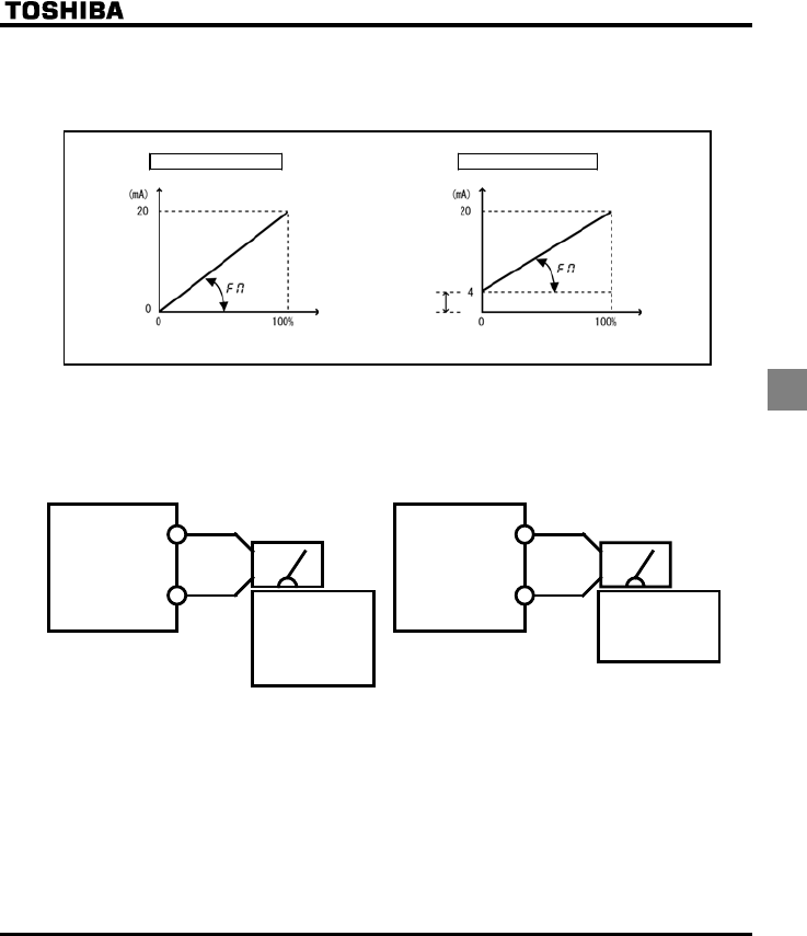
E6581381
E-11
5
■Resolution
All FM terminals have a maximum of 1/1000.
■Example of 4-20mA output adjustment ⇒ For details, see section 6.19.1.
H=1, H=0 H=1, H=20
H
Output
currrent
Output
currrent
Internal calculated value Internal calculated value
Note 1: When using the FM terminal for current output, be sure that the external load resistance is less than 750Ω.
Note 2: Note that, if HOUN is set to (torque), data will be updated at intervals of more than 40 ms.
■Adjustment scale with parameter HO (Meter adjustment)
Connect meters as shown below.
FM
CC
Meter: Frequency meter
(def ault setting)
VF-FS1
FM
CC
VF-FS1
The reading of the
frequency meter
will fluctuate during
scale adjustment.
Meter: ammeter
(HOUN=)
The reading of the
ammeter will
fluctuate during
scale adjustment.
+
-
+
-
* Optional frequency meter: QS-60T
* Make the maximum ammeter scale at least 120 percent
of the inverter's rated output current.
<Frequency mete
r
>
<Ammeter>
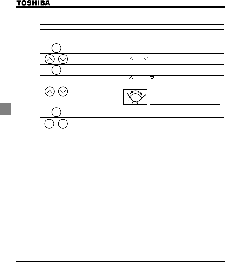
E6581381
E-12
5
■Example of how to adjustment the FM terminal frequency meter
* Use the meter's adjustment screw to pre-adjust zero-point.
Key operated LED display Operation
-.
Displays the operation frequency.
(When standard monitor display selection H is set to [Operation
frequency])
CWH The first basic parameter “CWH” (Wizard function) is displayed.
HO Press either the or the key to select “HO”.
. Press the ENT key to display the operation frequency
.
Press either the key or the key to adjust the meter.
The meter reading will change at this time but be careful because there
will be no change in the inverter's digital LED (monitor) indication.
⇔ HO The adjustment is complete. HO and the frequency are displayed
alternately.
+.
The display returns to its original indications.
(When standard monitor display selection H is set to [Operation
frequency])
■Adjusting the meter in inverter stop state
•Adjustment of output current (HOUN=)
If, when adjusting the meter for output current, there are large fluctuations in data during adjustment,
making adjustment difficult, the meter can be adjusted in inverter stop state.
When setting HOUN to for fixed output 1 (100% output current), a signal of absolute values will be
output (inverter's rated current = 100%). In this state, adjust the meter with the HO (Meter adjustment)
parameter.
Similarly, if you set HOUN to for fixed output 2 (output current at 50%), a signal that is sent out when
half the inverter's rated current is flowing will be output through the FM terminal.
After meter adjustment is ended, set HOUN to (output current).
•Adjustment of other items (HOUN=, to , )
If parameter HOUN is set to : Fixed output 3 (Other than the output current: 100%), a signal that is
sent out when HOUN is set to , to , (100%) will be output through the FM terminal.
100% standard value for each item is the following:
HOUN=, , : Maximum frequency (HJ)
HOUN=, : 1.5 times of rated voltage
HOUN=, : 1.85 times of rated power
HOUN=, : 2.5 times of rated torque
HOUN=, : Rated load factor
HOUN=, : Maximum input value
HOUN= : FA51=1000
[Hint]
It's easier to make the adjustment if you
push and hold for several seconds.
ENT
MODE
ENT
MODE MODE

E6581381
E-13
5
5.5 Standard default setting
V[R : Default setting
•Function
Allows setting of all parameters to the standard default setting, etc. at one time.
Note that HO, HOUN, H, H ∼ H and H will not be reset to their factory
default settings.
Title Function Adjustment range Default setting
V[R Default setting
0: -
1: 50Hz default setting
2: 60Hz default setting
3: Standard default setting
(Initialization)
4: Trip record clear
5: Cumulative operation time clear
6: Initialization of type information
7: Save user-defined parameters
8: Call user-defined parameters
9: Cumulative fan operation time
record clear
0
+This function will be displayed as 0 during reading on the right. This previous setting is displayed.
Example:
+V[R cannot be set during the inverter operating. Always stop the inverter first and then program.
Programmed value
50Hz default setting (V[R = )
Setting V[R at causes all the following parameters to be set for operation using a base frequency of 50
Hz. (This does not change the setting of any other parameters.)
Parameter HJ, WN, XN, H, H, H, H: 50Hz
Parameter H: According to model
⇒ See page K-14.
50Hz default setting (V[R = )
Setting V[R at causes all the following parameters to be set for operation using a base frequency of 60
Hz. (This does not change the setting of any other parameters.)
Parameter HJ, WN, XN, H, H, H, H: 60Hz
Parameter H: According to model
⇒ See page K-14.

E6581381
E-14
5
Default setting (V[R = )
Setting V[R to will return all parameters to the standard values that were programmed at the factory.
⇒ See section 4.2.7.
+When 3 is programmed, <KPKV will be displayed for a short time after setting and will then be erased
and displayed the original indication .. Trip history data will be cleared at this time.
Trip clear (V[R = )
Setting V[R to initializes the past four sets of recorded error history data.
+The parameter does not change.
Cumulative operation time clear (V[R = )
Setting V[R to resets the cumulative operation time to the initial value (zero).
Cumulative operation time clear (V[R = )
Setting V[Rto clears the trips when an GV[R format error occurs. But if the GV[R displayed, call us.
Save user setting parameters (V[R = )
Setting V[R to saves the current settings of all parameters.
⇒ See section 4.2.8.
Load user setting parameters (V[R = )
Setting V[R to loads parameter settings to (calls up) those saved by setting V[R to .
⇒ See section 4.2.8.
+By setting V[R to or , you can use parameters as your own default parameters.
Cumulative fan operation time record clear (V[R = )
Setting V[R to resets the cumulative operation time to the initial value (zero).
Set this parameter when replacing the cooling fan, and so on.
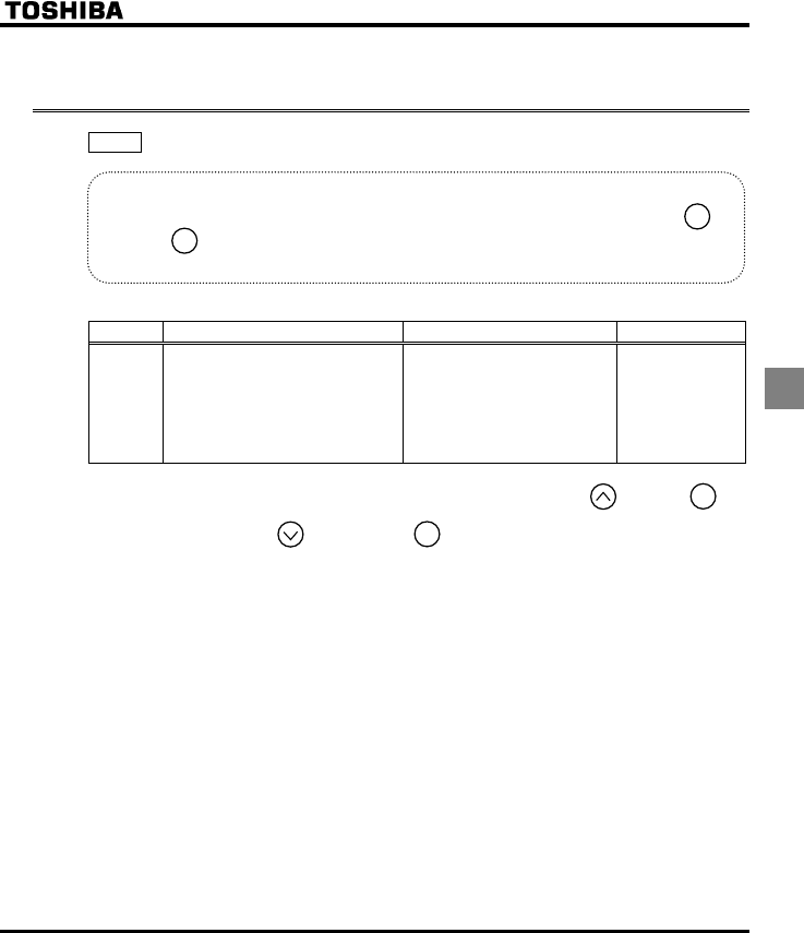
E6581381
E-15
5
5.6 Forward/reverse run selection (Operation panel
operation)
HT : Forward/reverse run selection (Operation panel operation)
•Function
Program the direction of rotation of the motor when the running and stopping are made using the
key and key on the operation panel.
Valid when EOQF (command mode) is set to (operation panel).
[Parameter setting]
Title Function Adjustment range Default setting
HT Forward/reverse run selection
(Operation panel operation)
0: Forward run
1: Reverse run
2: Forward run (F/R switching
possible)
3: Reverse run (F/R switching
possible)
0
+When HT is set to or and an operating status is displayed, pressing the key with the key
held down changes the direction of rotation from reverse to forward after displaying the message
“HTH” Pressing the key again with the key held down changes the direction of rotation
from forward to reverse after displaying the message “HTT”
+Check the direction of rotation on the status monitor.
⇒ For monitoring, see section 8.1
HTH: Forward run
HTT: Reverse run
+When the F and R terminals are used for switching between forward and reverse rotation from the
terminal board, the HT forward/reverse run selection parameter is rendered invalid.
Short across the F-CC terminals: forward rotation
Short across the R-CC terminals: reverse rotation.
+The inverter was factory-configured by default so that shorting terminals F-CC and terminals R-CC
simultaneously would cause the motor to slow down to a stop.
Using the parameter H, however, you can select between forward run and reverse run.
+This function is valid only when EOQF is set to (operation panel).
ENT
RUN
STOP
ENT
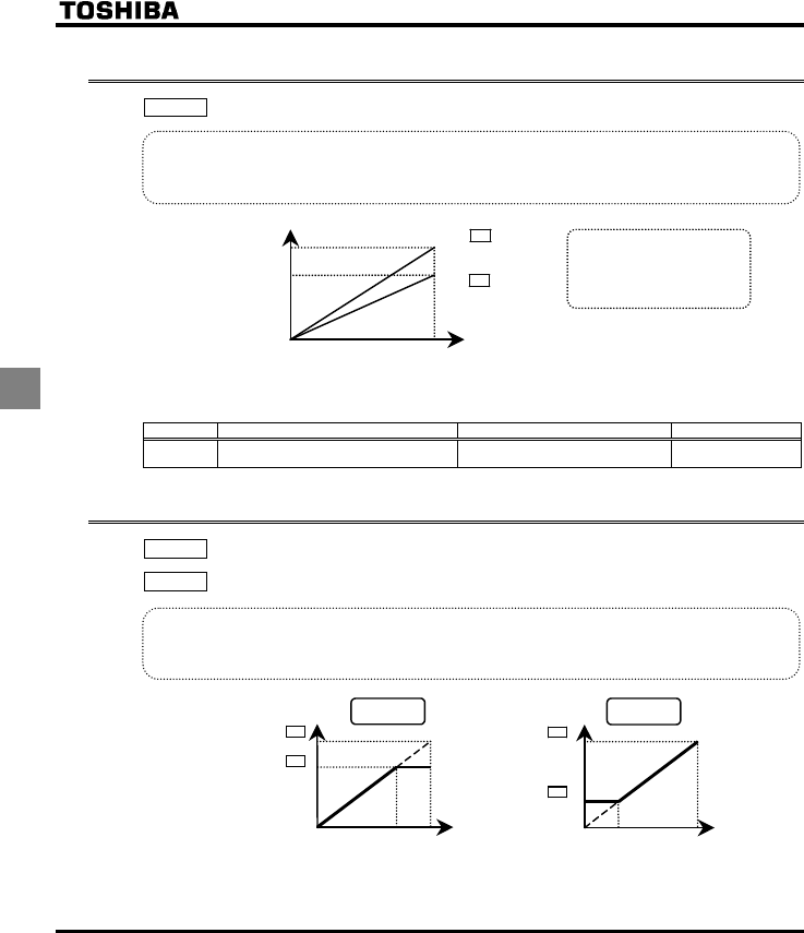
E6581381
E-16
5
5.7 Maximum frequency
HJ: Maximum frequency
•Function
1) Programs the range of frequencies output by the inverter (maximum output values).
2) This frequency is used as the reference for acceleration/deceleration time.
Output frequency
(Hz) When HJ=80Hz
When HJ=60Hz
80Hz
60Hz
0 100% Frequency setting signal (%)
・This function determines the value
in line with the ratings of the motor
and load.
・Maximum frequency cannot be
adjusted during operation.To
adjust, first stop the inverter.
+If HJ is increased, adjust the upper limit frequency WN as necessary.
[Parameter setting]
Title Function Adjustment range Default setting
HJ Maximum frequency 30.0-200.0 (Hz) 80.0
5.8 Upper limit and lower limit frequencies
WN: Upper limit frequency
NN: Lower limit frequency
•Function
Programs the lower limit frequency that determines the lower limit of the output frequency and the upper
limit frequency that determines the upper limit of that frequency.
0 100%
Output frequency (Hz)
WN
HJ
Frequency setting signal
* Frequencies that go
higher than WN will not
be output.
Upper limit
frequency
0 100%
Output frequency (Hz)
HJ
NN
Frequency setting signal
* The output frequency
cannot be set at less than
NN.
Lower limit
frequency
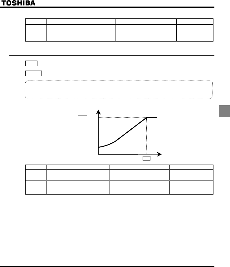
E6581381
E-17
5
[Parameter setting]
Title Function Adjustment range Default setting
WN Upper limit frequency 0.5 - HJ (Hz) 50.0 (WP type)
60.0 (WN type)
NN Lower limit frequency 0.0 - WN (Hz) 0.0
5.9 Base frequency
XN : Base frequency 1
XNX : Base frequency voltage 1
•Function
Sets the base frequency and the base frequency voltage in conformance with load specifications or the
Base frequency.
Note:This is an important parameter that determines the constant torque control area.
Output voltage [V]
Base frequency voltage
XNX
XN Output frequency (Hz)
0
Title Function Adjustment range Default setting
XN Base frequency 1 25.0-200.0 (Hz) 50.0 (WP type)
60.0 (WN type)
XNX Base frequency voltage1 50-330 (V) : 200V class
50-660 (V) : 400V class
230 (WP/WN type)
400 (WP type)
460 (WN type)
E6581381
E-18
5
5.10 Selecting control mode
RV : V/F control mode selection
•Function
With VF-FS1, the V/F controls shown below can be selected.
{ V/F constant
{ Variable torque
{ Automatic torque boost control
{ Vector control
{ Energy saving
{ PM motor control
[Parameter setting]
Title Function Adjustment range Default setting
RV V/F control mode selection
0: V/F constant
1: Variable torque
2: Automatic torque boost control
3: Vector control
4: Energy-saving
5: - (Do not select)
6: PM motor control
1
Steps in setting are as follows
(In this example, the V/F control mode selection parameter RV is set to (Vector control).
■Setting V/F control mode selection to 3 (sensorless vector control)
Key operated LED display Operation
.
Displays the operation frequency. (Perform during operation stopped.)
(When standard monitor display selection H is set to
[Operation frequency])
CWH The first basic parameter “CWH” (Wizard function) is displayed.
RV Press the key to change the parameter to RV (V/F control mode
selection).
Press the ENT key to display the parameter setting. (Standard
default setting: ( Variable torque)).
Press the key to change the parameter to (vector control).
⇔ RV Press the ENT key to save the changed parameter. RV and
parameter set value “” are displayed alternately.
MODE
ENT
ENT
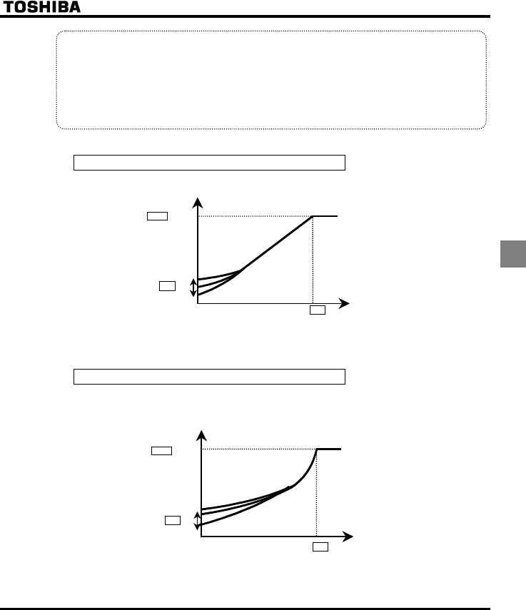
E6581381
E-19
5
Warning:
When setting the V/F control mode selection parameter (RV) to any number between and , be sure
to set at least the following parameters.
H (Motor rated current): See the motor's nameplate.
H (No-load current of motor): Refer to the motor test report.
H (Rated rotational speed of motor): See the motor's nameplate.
Set also other torque boost parameters (H to H), as required.
1) Constant torque characteristics
Setting of V/F control mode selection RV to (V/F constant)
This is applied to load that requires the same torque at low speeds as at rated speeds.
Output voltage(%)
Base frequency voltage
XNX
Output frequency (Hz)
XD
Base frequency XN
0
* To increase the torque further, increase the setting value of the manual torque boost XD.
⇒ For more details, see 5.11.
2) Setting for fans and pumps
Setting of V/F control mode selection RV to (variable torque)
This is appropriate for load characteristics of such things as fans, pumps and blowers in which the torque in
relation to load rotation speed is proportional to its square.
Output voltage(%)
Base frequency voltage
XNX
XD
Base frequency XN
0
Output frequency (Hz)
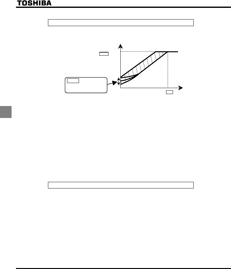
E6581381
E-20
5
3) Increasing starting torque
Setting of V/F control mode selection RV to (automatic torque boost control)
Detects load current in all speed ranges and automatically adjusts voltage output (torque boost) from inverter.
This gives steady torque for stable runs.
H :Automatically
adjusts the
amountof torque
boost.
Output voltage(%)
Base frequency voltage
XNX
Output frequency (Hz)Base frequency XN
0
Note: This control system can oscillate and destabilize runs depending on the load. If that should
happen, set V/F control mode selection RV to (V/F constant) and increase torque manually.
+Motor constant must be set
If the motor you are using is a 4P Toshiba standard motor and if it has the same capacity as the inverter,
there is basically no need to set the motor constant. In any other case, be sure to set the parameters H
to H properly.
Be sure to set H (rated current of motor) and H (rated speed of motor) correctly, as specified on
the motor’s nameplate. For the setting of H (no-load current of motor), refer to the motor test report.
There are two procedures for setting the other motor constants.
1) The motor constant can be automatically set (auto-tuning). Set the extended parameter H to .
⇒ For details, see selection 1 in 6.15.1.
2) Each motor constant can be set individually. ⇒ For details, see selection 2 in 6.15.1.
4) Vector control - increasing starting torque and achieving high-precision operation.
Setting of V/F control mode selection RV to (Vector control)
Using sensor-less vector control with a Toshiba standard motor will provide the highest torque at the low
speed ranges.
(1) Provides large starting torque.
(2) Effective when stable operation is required to move smoothly up from the low speeds.
(3) Effective in elimination of load fluctuations caused by motor slippage.

E6581381
E-21
5
+Motor constant must be set
If the motor you are using is a 4P Toshiba standard motor and if it has the same capacity as the inverter,
there is basically no need to set the motor constant. In any other case, be sure to set the parameters H
to H properly.
Be sure to set H (rated current of motor) and H (rated speed of motor) correctly, as specified on
the motor’s nameplate. For the setting of H (no-load current of motor), refer to the motor test report.
There are two procedures for setting the other motor constants.
1) The motor constant can be automatically set (auto-tuning).
Set the extended parameter H to .⇒ For details, see selection 1 in 6.15.1.
2) Each motor constant can be set individually. ⇒ For details, see selection 2 in 6.15.1.
5) Energy-saving
Setting of V/F control mode selection RV to (Energy-saving)
Energy can be saved in all speed areas by detecting load current and flowing the optimum current that fits
the load.
+Motor constant must be set
If the motor you are using is a 4P Toshiba standard motor and if it has the same capacity as the inverter,
there is no need to set the motor constant. In any other case, be sure to set the parameters H to
H properly.
Be sure to set H (rated current of motor) and H (rated speed of motor) correctly, as specified on
the motor’s nameplate. For the setting of H (no-load current of motor), refer to the motor test report.
There are two procedures for setting the other motor constants.
1) The motor constant can be automatically set (auto-tuning). Set the extended parameter H to .
⇒ For details, see selection 1 in 6.15.1.
2) Each motor constant can be set individually. ⇒ For details, see selection 2 in 6.15.1.
6) Operating a permanent magnet motor
Setting of V/F control mode selection RV to (PM motor control)
Permanent magnet motors (PM motors) that are light, small in size and highly efficient, as compared to
induction motors, can be operated in sensor-less operation mode.
Note that this feature can be used only for specific motors. For more information, contact your Toshiba dealer.
7) Precautions on vector control
1) When exercising vector control, be sure to set the extended parameters H to H properly. Be
sure to set H (rated current of motor) and H (rated speed of motor) correctly, as specified on
the motor’s nameplate. For the setting of H (no-load current of motor), refer to the motor test report.
2) The sensorless vector control exerts its characteristics effectively in frequency areas below the base
frequency (XN). The same characteristics will not be obtained in areas above the base frequency.
3) Set the base frequency to anywhere from 40 to 120Hz during vector control (RV=).
4) Use a general purpose squirrel-cage motor with a capacity that is the same as the inverter's rated capacity or
one rank below.
The minimum applicable motor capacity is 0.1kW.

E6581381
E-22
5
5) Use a motor that has 2-8 P.
6) Always operate the motor in single operation (one inverter to one motor). Sensorless vector control
cannot be used when one inverter is operated with more than one motor.
7) The maximum length of wires between the inverter and motor is 30 meters. If the wires are longer than 30
meters, set standard auto-tuning with the wires connected to improve low-speed torque during sensorless
vector control.
However the effects of voltage drop cause motor-generated torque in the vicinity of rated frequency to be
somewhat lower.
8) Connecting a reactor or surge voltage suppression filter between the inverter and the motor may reduce
motor-generated torque. Setting auto-tuning may also cause a trip (GVP) rendering sensorless vector
control unusable.
8) The following table shows the relationship between the V/F control mode
selection (RV) and the motor constant parameter.
Under normal conditions, be sure to set or adjust the parameters marked with .
When making detailed settings, adjust the parameters marked with c as well, if necessary.
Do not adjust the parameters marked with °, because they are invalid.
(For instructions about how to adjust the parameter H and later, see section 6.17.)
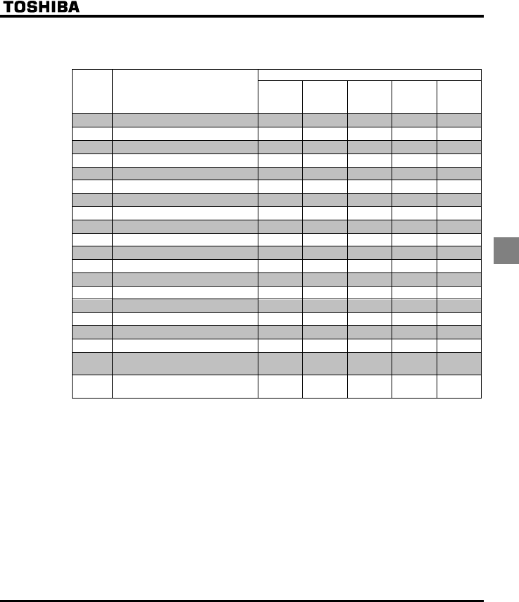
E6581381
E-23
5
■Relationship between V/F control mode selection (RV) and Motor constant
parameter
&c : Valid, ° : Invalid
Parameter RV (V/F control mode selection)
01234
Title Function V/F
constant
Variabl e
torque
Automatic
torque boost
control
Vector
control
Energy-
saving
XN Base frequency 1
XNX Base frequency voltage 1
XD Torque boost value 1 °°°
H Base frequency 2 c°°°°
H Base frequency voltage 2 c°°°°
H Torque boost value 2 c°°°°
H Auto-tuning °°ccc
H Slip frequency gain °°°c°
H Automatic torque boost value °°
H Motor rated current cc
H Motor no-load current °°ccc
H Motor rated speed cc
H Speed control response coefficient °°ccc
H Speed control stability coefficient °°ccc
H Exciting current coefficient °°cc°
H Stall prevention control coefficient 1 ccccc
H Stall prevention control coefficient 2 ccccc
H Motor adjustment coefficient ccccc
H Maximum voltage adjustment
coefficient ccccc
H Waveform switching adjustment
coefficient ccccc
: Be sure to set and adjust the parameters.
c : Adjust the parameters if necessary.
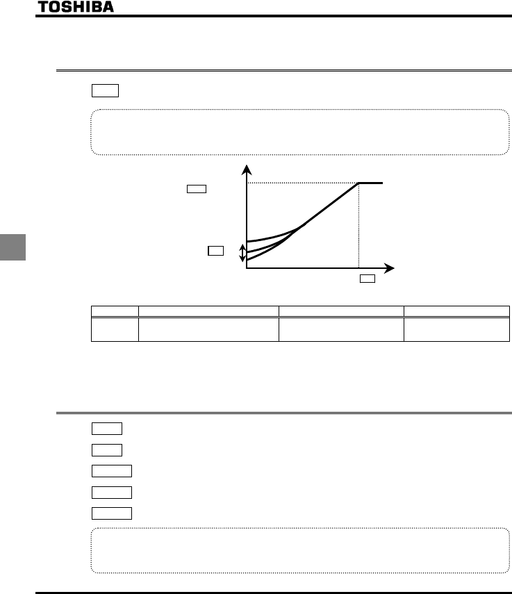
E6581381
E-24
5
5.11 Manual torque boost - increasing torque boost at low
speeds
XD : Torque boost 1
•Function
If torque is inadequate at low speeds, increase torque by raising the torque boost rate with this
parameter.
Output voltage
[V]/(%)
Base frequency voltage
Output frequency (Hz)
XD
Base frequency XN
XNX
[Parameter setting]
Title Function Adjustment range Default setting
XD Torque boost 1 0.0 - 30.0 (%) According to model
(⇒ See page K-14)
+Valid when RV is set to (V/F constant) or (square reduction)
Note: The optimum value is programmed for each inverter capacity. Be careful not to increase the torque boost
rate too much because it could cause an overcurrent trip at startup.
5.12 Setting the electronic thermal
VJT : Motor electronic-thermal protection level 1
QNO : Electronic thermal protection characteristic selection
H : Motor electronic-thermal protection level 2
H : Motor 150%-overload time limit
H : Thermal memory selection
•Function
This parameter allows selection of the appropriate electronic thermal protection characteristics according
to the particular rating and characteristics of the motor.
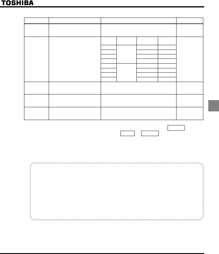
E6581381
E-25
5
[Parameter setting]
Title Function Adjustment range Default setting
VJT Motor electronic thermal
protection level 1 10 – 100 (%) / (A) 100
Setting
value
Overload
protection
Overload
stall
0{×
1{{
2××
3
Standard
motor
×{
4{×
5{{
6××
QNO Electronic-thermal protection
characteristic selection
7
VF motor
(special
motor) ×{
{
H Motor electronic-thermal
protection level 2 10 – 100 (%) / (A) 100
H Motor 150%-overload time
limit 10 – 2400 (s) 300
H Thermal memory selection 0: Disabled
1: Enabled 0
* { : valid, × : invalid
1) Setting the electronic thermal protection characteristics selection QNO and
motor electronic thermal protection level 1 VJT, 2 H
The electronic thermal protection characteristics selection QNO is used to enable or disable the motor
overload trip function (QN) and the overload stall function.
While the inverter overload trip (QN) will be in constant detect operation, the motor overload trip (QN)
can be selected using the parameter QNO
Explanation of terms
Overload stall: This is an optimum function for equipment such as fans, pumps and blowers with
variable torque characteristics that the load current decreases as the operating speed
decreases.
When the inverter detects an overload, this function automatically lowers the output
frequency before the motor overload trip QN is activated. This function operates a
motor at frequencies that allow the load current to keep its balance so that the
inverter can continue operation without being tripped.
Note: Do not use the overload stall function with loads having constant torque characteristics (such as
conveyor belts in which load current is fixed with no relation to speed).
[Using standard motors (other than motors intended for use with inverters)]
When a motor is used in the lower frequency range than the rated frequency, that will decrease the cooling
effects for the motor. This speeds up the start of overload detection operations when a standard motor is
used in order to prevent overheating.
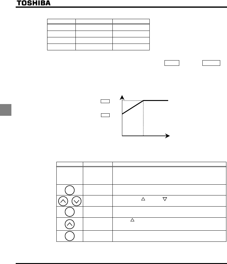
E6581381
E-26
5
■Setting of electronic thermal protection characteristics selection QNO
Setting value Overload protection Overload stall
{×
{{
××
×{
{ : valid, × : invalid
■Setting of motor electronic thermal protection level 1 VJT (Same as H)
If the capacity of the motor is smaller than the capacity of the inverter, or the rated current of the motor
is smaller than the rated current of the inverter, adjust the electronic thermal protection level 1 VJT so
that it fits the motor's rated current.
VJT×0.55
VJT×1.0
Output frequency (Hz)
Output current reduction factor
[%]/[A]
0
30Hz
Note: The motor overload protection start level is fixed at 30Hz.
[Example of setting: When the VFFS1-2007PM is running with a 0.4kW motor having 2A rated current]
Key operated LED display Operation
Displays the operation frequency. (Perform during operation
stopped.)
(When standard monitor display selection H is set to
[Operation frequency])
CWH The first basic parameter “CWH” (Wizard function) is displayed.
VJT Press either the key or the key to change the parameter to
VJT.
Press the ENT key to display the parameter setting. (Standard
default setting: 100%)
Press the key to change the parameter to %
(=motor rated current/inverter output rated current x
100=2.0//4.8×100).
¶⇔¶VJT Press the ENT key to save the changed parameter. VJT and the
parameter are displayed alternately.
Note: The rated output current of the inverter should be calculated from the rated current, regardless of the
setting of the PWM carrier frequency parameter (H).
MODE
ENT
ENT
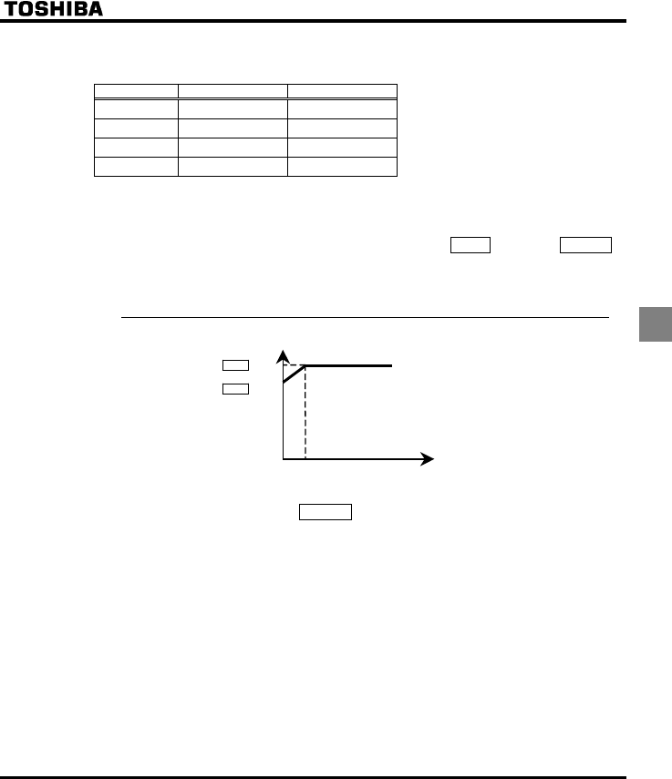
E6581381
E-27
5
[Using a VF motor (motor for use with inverter)]
■Setting of electronic thermal protection characteristics selection QNO
Setting value Overload protection Overload stall
{×
{{
××
×{
{ : valid, × : invalid
VF motors (motors designed for use with inverters) can be used in frequency ranges lower than those
for standard motors, but their cooling efficiency decreases at frequencies below 6Hz.
■Setting of motor electronic thermal protection level 1VJT (Same as H)
If the capacity of the motor is smaller than the capacity of the inverter, or the rated current of the motor
is smaller than the rated current of the inverter, adjust the electronic thermal protection level 1 VJT so
that it fits the motor's rated current.
* If the indications are in percentages (%), then 100% equals the inverter's rated output current (A).
VJT×1.0
Output frequency (Hz)
Output current reduction factor [%]
/
[A]
0
Setting the motor overload starting level
6Hz
VJT×0.6
2) Motor 150%-overload time limit H
Parameter H is used to set the time elapsed before the motor trips under a load of 150% (overload trip
QN) within a range of 10 to 2400 seconds.
3) Inverter over load characteristics
Set to protect the inverter unit. Cannot be changed or turned off by parameter setting.
To prevent the inverter overload trip function (QN) from being activated too easily, lower the stall
prevention level (H) or increase the acceleration time (CEE) or deceleration time (FGE).
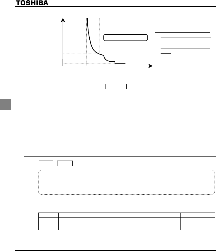
E6581381
E-28
5
105%110%Output current [%]
Time [sec]
60
Inverter overload
0
100% = inverter rated output current
0.25
185%
Inverter overload protection characteristics
* To protect the inverter, overload
trip or overcurrent trip activate in
a short period of time when
output current reaches 110% or
higher.
4) Thermal memory selectionH
At the main power off, it is selectable whether retention of electric thermal calculation values or not.
: Incase of not activated
The calculated value of the electric thermal is not memorized at power-off.
The calculated value of the electric thermal and the trip state can always be reset.
Don’t reset the unit trip state continually, it may cause the motor and the unit failure.
: In case of activated
The calculated value of the electric thermal is memorized at power-off.
The trip state can always be reset but the calculated value of the electric thermal can not be reset.
5.13 Preset-speed operation (speeds in 7 steps)
UT - UT : Preset-speed operation frequencies 1-7
•Function
A maximum of 7 speed steps can be selected just by switching an external contact signal. Multi-speed
frequencies can be programmed anywhere from the lower limit frequency NN to the upper limit frequency
WN.
[Setting method]
1) Run/stop
The starting and stopping control is done from the terminal board.
Title Function Adjustment range Setting value
EOQF Command mode selection
0: Terminal board
1: Operation panel
2: Serial communication
0
Note:If speed commands (analog signal or digital input) are switched in line with preset-speed operations, select
the terminal board using the frequency setting mode selection HOQF.⇒ See step 3) or section 5.3.
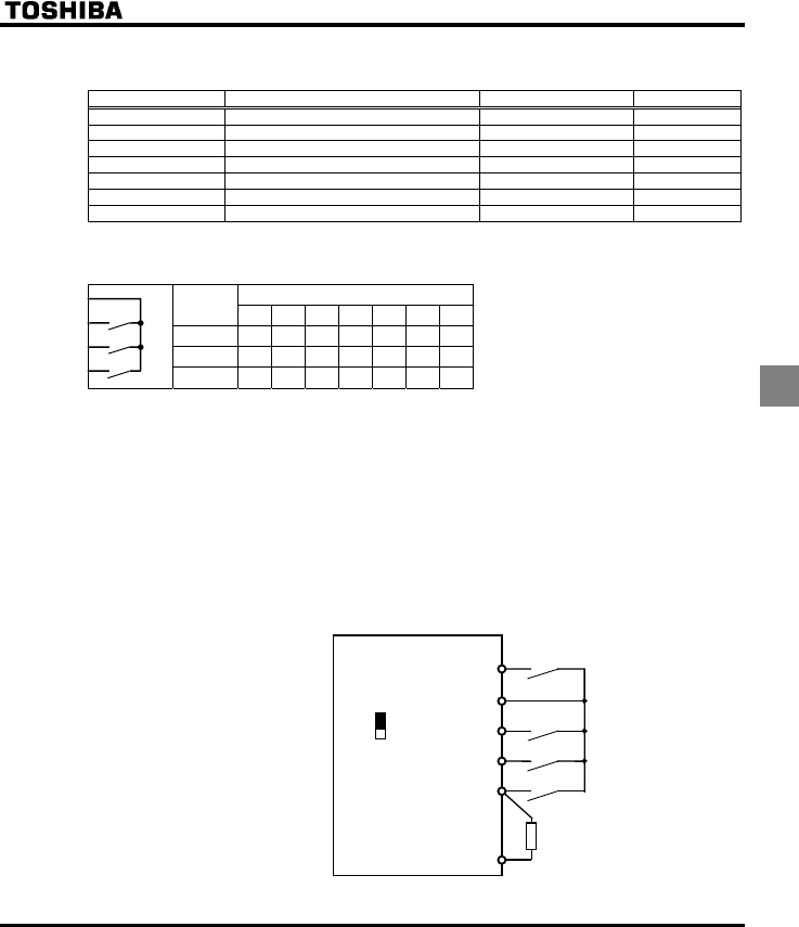
E6581381
E-29
5
2) Preset-speed frequency setting
Set the speed (frequency) of the number of steps necessary.
Title Funtion Adjustment range Default setting
UT Preset-speed operation frequencies 1 NN WN(Hz) 15.0
UT Preset-speed operation frequencies 2 NN WN(Hz) 20.0
UT Preset-speed operation frequencies 3 NN WN(Hz) 25.0
UT Preset-speed operation frequencies 4 NN WN(Hz) 30.0
UT Preset-speed operation frequencies 5 NN WN(Hz) 35.0
UT Preset-speed operation frequencies 6 NN WN(Hz) 40.0
UT Preset-speed operation frequencies 7 NN WN(Hz) 45.0
Examples of preset-speed contact input signals: Slide switch SW4 set to sink logic
O: ON -: OFF (Speed commands other than preset-speed commands are valid when all are OFF)
Preset-speed
Terminal 1234567
R-CC {-{-{-{
RES-CC - {{ --
{{
VIA-CC - - - {{{{
+Preset-speed commands are not allocated to standard default setting. Use the input terminal function
selection to allocate SS1 to SS3 terminal.
Terminal R............... Input terminal function selection 2 (R)
H= (Preset-speed command 1: SS1)
Terminal RES.......... Input terminal function selection 3 (RES)
H= (Preset-speed command 2: SS2)
Terminal VIA ........... Input terminal function selection 8 (VIA)
H= (Preset-speed command 3: SS3)
Analog/contact input function selection
H= (VIA-contact input(Sink))
[Example of a connection diagram]
(SW4 set to sink logic)
F (Forward run)
CC
P24
RES
VIA
R
Forward
Preset-speed 1 (SS1)
Preset-speed 3 (SS3)
Preset-speed 2 (SS2)
Common
VIA
V
I
SW3
CC
R
RES
VIA
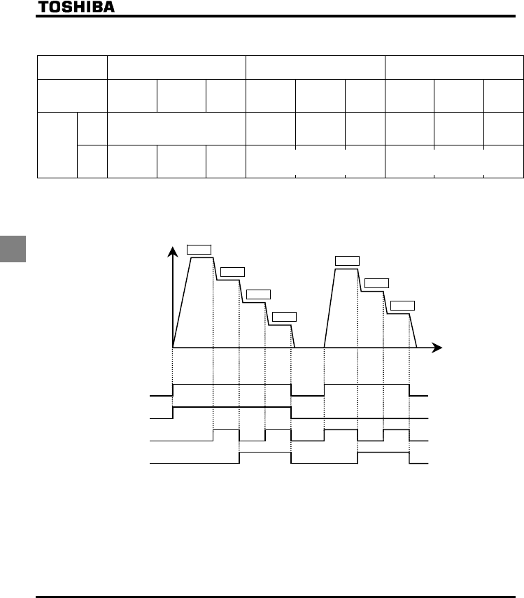
E6581381
E-30
5
3) Using other speed commands with preset-speed command
Command mode
selection
EOQF
0: Terminal board 1: Operation panel 2: Serial communication
Frequency setting
mode selection
HOQF
1: VIA
2: VIB
5: UP/DOWN
3: Operation
panel
4:Commun
ication
1: VIA
2: VIB
5: UP/DOWN
3: Operation
panel
4:Commun
ication
1: VIA
2: VIB
5: UP/DOWN
3: Operation
panel
4:Commun
ication
Entered Preset-speed command valid Note)
Terminal
command
valid
Operation
panel
command
valid
Terminal
command
valid
Operation
panel
command
valid
Communicatio
n command
valid
Communic
ation
command
valid
Preset-
speed
command Not
entered
Terminal
command
valid
Operation
panel
command
valid
Communic
ation
command
valid
Note: The preset-speed command is always given priority when other speed commands are input at the
same time.
Below is an example of 7-step speed operation.
ON
OFF
F-CC
R-CC
RES-CC
VIA-CC
ON
OFF
ON
OFF
ON
OFF
UT
UT
UT
UT
UT
UT
UT
Output frequency
[Hz]
Time
[sec]
0
Example of 7-step speed operation
(The inverter doesn't accept Preset-
speed command.)
(The inverter doesn't accept Preset-
speed command.)
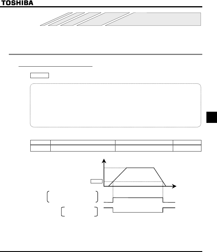
E6581381
F-1
6
6. Extended parameters
Extended parameters are provided for sophisticated operation, fine adjustment and other special purposes. Modify
parameter settings as required. ⇒ See section 11, table of extended parameters.
6.1 Input/output parameters
6.1.1 Low-speed signal
H : Low-speed signal output frequency
•Function
When the output frequency exceeds the setting of H an ON signal will be generated. This signal
can be used as an electromagnetic brake excitation/release signal.
This signal can also be used as an operation signal when H is set to 0.0Hz, because an ON
signal is put out if the output frequency exceeds 0.0Hz.
+Relay output (250Vac-1A (cosφ=1), 30Vdc-0.5A, 250Vac-0.5A (cosφ=0.4)
at RY-RC, FLA-FLC-FLB terminals.
[Parameter setting]
Title Function Adjustment range Default setting
H Low-speed signal output frequency 0.0 ∼ HJ (Hz) 0.0
Output frequency
Time [s]
H
Low-speed signal output
RY-RC terminals (Default setting)
FLA-FLC-FLB terminals ON
OFF
Low-speed signal output:
Inverted
ON
OFF
[Hz]
0
Set frequency
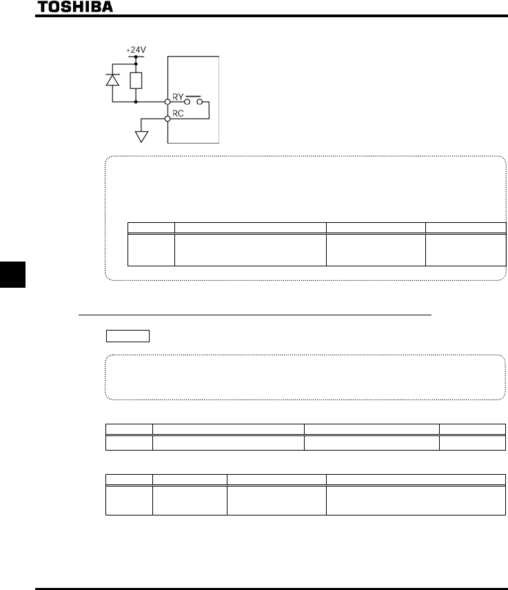
E6581381
F-2
6
An example of the connection of the relay output terminals
•Output terminal setting
Output of the low-speed signal (ON signal) between the RY and RC terminals is the factory default
setting of the output terminal selection parameter. This setting must be changed to invert the polarity of
the signal.
[Parameter setting]
Title Function Adjustment range Setting value
H Output terminal selection 1A (RY-RC) 0-255
(⇒ See page K-17)
4 (ON signal)
or
5 (OFF signal)
6.1.2 Output of designated frequency reach signal
H : Speed reach detection band
•Function
When the output frequency becomes equal to the setting by designated frequency ±H, an ON or
OFF signal is generated.
[Parameter setting]
Title Function Adjustment range Default setting
H Speed reach detection band 0.0 ∼ HJ (Hz) 2.5
[Parameter setting]
Title Function Adjustment range Setting value
H
Output terminal
selection 1A
(RY-RC)
0-255
(⇒ See page K-17)
6: RCH (designated frequency - ON signal), or
7: RCHN (designated frequency - OFF signal)
Note: Select the H parameter to specify FLA-FLC-FLB terminal output.
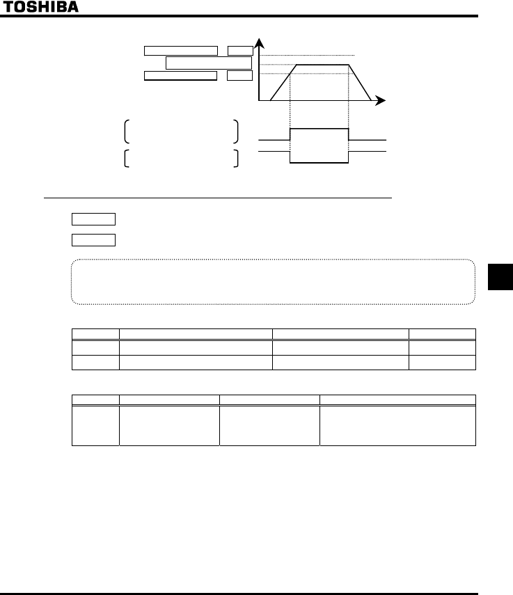
E6581381
F-3
6
Output frequency [Hz]
Time [s]
Designated frequency − H
ON
OFF
Designated frequency + H
Designated frequency
Set frequency speed reach signal
RY-RC
FLA/FLC/FLB
Set frquency spped reach signal:
Inverted
ON
OFF
0
6.1.3 Output of set frequency speed reach signal
H : Speed reach setting frequency
H : Speed reach detection band
•Function
When the output frequency becomes equal to the frequency set by H ± H, an ON or
OFF signal is generated.
[Parameter setting]
Title Function Adjustment range Default setting
H Speed reach setting frequency 0.0 ∼ HJ (Hz) 0.0
H Speed reach detection band 0.0 ∼ HJ (Hz) 2.5
[Parameter setting]
Title Function Adjustment range Setting value
H
Output terminal
selection 1A
(RY-RC)
0-255
(⇒ See page K-17)
8: RCHF (designated frequency - ON
signal), or
9: RCHFN (designated frequency -
OFF signal)
Note: Select the H parameter function No. 8 or 9 to specify FLA-FLC-FLB terminal output.
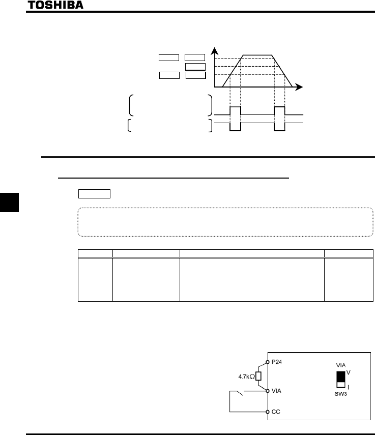
E6581381
F-4
6
If the detection band value + the set frequency is less than the designated frequency
Set frquency speed reach signal
RY-RC terminals
FLA-FLC-FLB terminals
Set frequency speed reach signal:
Inverted
Output frequency [Hz]
Time [s]
H - H
ON
OFF
H + H
H
ON
OFF
0
6.2 Input signal selection
6.2.1 Changing the functions of VIA terminal
H : VIA terminal function selection
•Function
This parameter allows you to choose between signal input and contact signal input for the VIA terminal.
[Parameter setting]
Title Function Adjustment range Default setting
H
Analog/contact input
function selection
(VIA terminal)
0: VIA - analog input
1: VIA - contact input (Sink)
2: VIA - contact input (Source)
0
* When using the VIA terminal as contact input terminals in sink logic connection, be sure to insert a
resistor between the P24 terminal and the VIA terminal. (Recommended resistance: 4.7kΩ-1/2W)
Note: When using the VIA terminal as a contact input terminal, be sure to turn the VIA (SW3) slide switch to
the V position.
+The figure on the right shows an example of the
connection of input terminal VIA when it is used as
contact input terminal. This example illustrates the
connection when the inverter is used in sink
(Negative) logic mode.
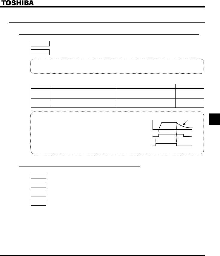
E6581381
F-5
6
6.3 Terminal function selection
6.3.1 Keeping an input terminal function always active (ON)
H : Always-active function selection 1
H : Always-active function selection 2
•Function
This parameter specifies an input terminal function that is always to be kept active (ON).
[Parameter setting]
Title Function Adjustment range Default setting
H Always-active function selection 1 0-71 (⇒ See page K-15) 0 (No function)
H Always-active function selection 2 0-71 (⇒ See page K-15) 1 (Standby)
* Coast stop
The standard default setting is for deceleration stop.
To make a coast stop, assign a "1(ST)" terminal
function to an idle terminal using the programmable
terminal function.
Change to H=.
For coast stop, OFF the ST terminal when stopping
the motor in the state described at left.The monitor on
the inverter at this time will display QHH.
Motor
speed
ON
OFF
ON
OFF
F terminal
ST terminal
Coast stop
6.3.2 Modifying input terminal functions
H
: Input terminal selection 1 (F)
H
: Input terminal selection 2 (R)
H
: Input terminal selection 3 (RES)
H
: Input terminal selection 8 (VIA)
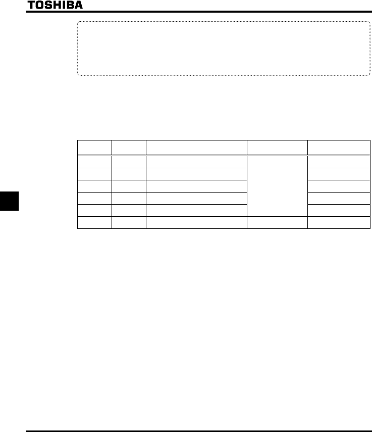
E6581381
F-6
6
•Function
Use the above parameters to send signals from an external programmable controller to various control
input terminals to operate and/or set the inverter.
The desired contact input terminal functions can be selected from 57 types (0 to 71). This gives system
design flexibility.
•The functions of the VIA terminal can be selected between analog input and contact input by changing
parameter settings H.
To use the VIA terminal as contact input terminals, you need to set H to the number (1 or 2) that
suits your needs, since analog input (voltage signal input) is assigned to the terminals by default.
■Setting of contact input terminal function
Terminal
symbol Title Function Adjustment range Default setting
-H Always-active function selection 1 0
-H Always-active function selection 2 1 (ST)
FH Input terminal selection 1 (F) 2 (F)
RH Input terminal selection 2 (R) 3 (R)
RES H Input terminal selection 3 (RES)
0-71
(⇒ See page K-15)
10 (RES)
VIA H Input terminal selection 8 (VIA) 0-71 Note 2) 6 (SS1)
Note 1: The function that has been selected using H and H (always-active function selection
parameter) are always activated.
Note 2: When using the VIA terminal as contact input terminals in sink logic connection, be sure to insert a
resistor between the P24 terminal and the VIA terminal. (Recommended resistance: 4.7kΩ-1/2W)
Be sure to turn the VIA (SW3) slide switch to the V position.
Note 3: H (VIA): Enabled only when H= or
Disabled and the set value cannot be read out, if H is set at .
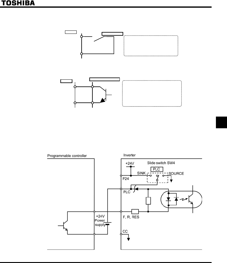
E6581381
F-7
6
■Connection method
1) A-contact input
CC
Input terminal
* This function is activated when the input
terminal and CC (common) are short-
circuited. Use this function to specify
forward/reverse run or a preset-speed
operation.
Inverter A-contact switch Sink setting
2) Connection with transistor output
* Operation can be controlled by connecting the
input and CC (c ommon) terminals to the
output (no-contacts switch) of the
programmable controller. Use this function to
specify forward/reverse run or a preset-speed
operation. Use a transistor that operates at
24Vdc/5mA.
CC
Input
terminal
Inverter Programmable controller
* Interface between programmable controller and inverter
Note: When using a programmable controller with open collector outputs for control, connect it to the
PCL terminal, as shown in the figure below, to prevent the inverter from malfunctioning
because of a current that flows in.
Also, be sure to turn the SW4 slide switch to the PLC position.
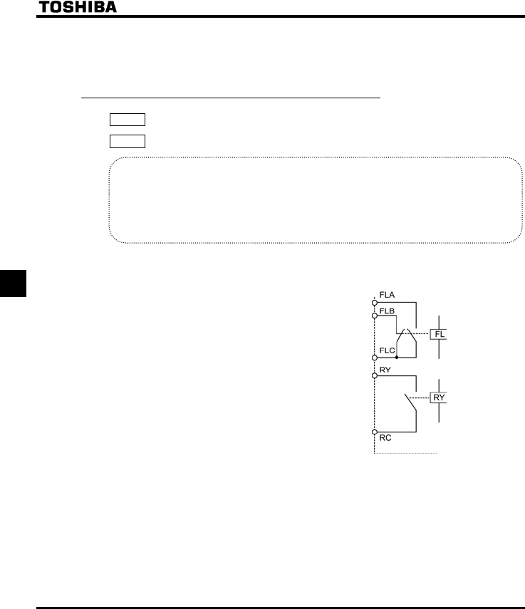
E6581381
F-8
6
3) Sink (Negative) logic / Source (Positive) logic input
Sink logic/source logic (input terminal logic) switching is possible.
⇒ For more details, see section 2.3.2.
6.3.3 Modifying output terminal functions
H
: Output terminal selection 1A (RY-RC)
H
: Output terminal selection 3 (FLA, FLB, FLC)
•Function
Use the above parameters to send various signals from the inverter to external equipment.
By setting parameters for the RY-RC and FL (FLA, FLB and FLC) terminals on the terminal board, you
can use 58 functions and functions obtained by combining them.
To assign only one function to RY-RC terminals, assign the function to H while leaving H
and H as they are set by default.
■Examples of application
Function of RY-RC:
Can be set using parameter H,,
Function of FLA, B, C:
Can be set using parameter H
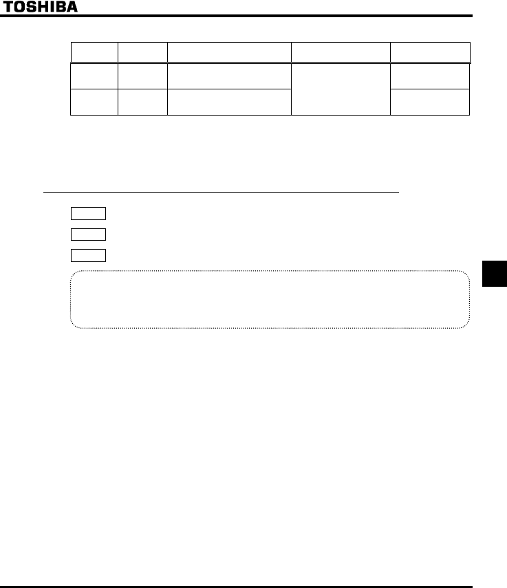
E6581381
F-9
6
■Assigning one function to an output terminal
Terminal
symbol Title Function Adjustment range Default setting
RY - RC H Output terminal selection 1A 4 (Low-speed
detection signal)
FL
(A, B, C)H Output terminal selection 3
0-255
(⇒ See page K-17) 10(Failure FL)
+When assigning one function to RY-RC terminals, set parameter H only.
Do not change but leave parameters H and H as they were set by default.
(Default setting: H=255, H=0)
6.3.4 Assigning two functions to an output terminal
H
: Output terminal selection 1A (RY-RC)
H
: Output terminal selection 1B (RY-RC)
H
: Output terminal logic selection (RY-RC)
•Function
2 different functions can be assigned to the terminal board output terminal RY-RC.
Signals of 2 functions of the logical product (AND) or logical sum (OR) selected form 58 functions can
be output to 1 output terminal.
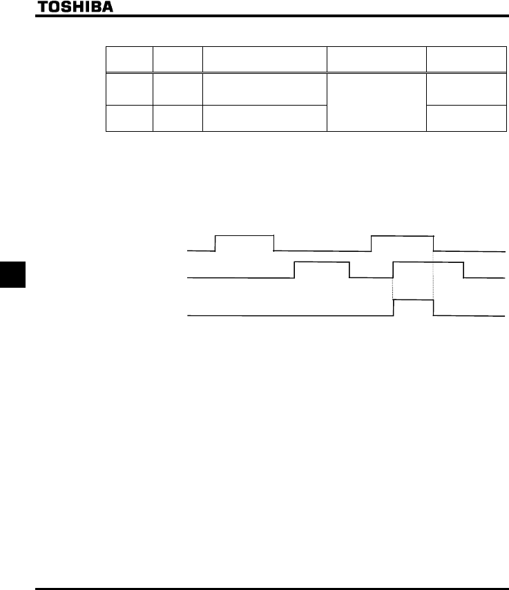
E6581381
F-10
6
(1) A signal is sent out when the two functions assigned are activated simultaneously.
Terminal
symbol Title Function Adjustment range Default setting
RY-RC H Output terminal selection 1A 4 (Low-speed
detection signal)
RY-RC H Output terminal selection 1B
0-255
(⇒ See page K-17)
255 (Always ON)
+Two different functions can be assigned to terminals RY-RC.
+If parameter H is set to (default), a signal will be sent out when the two functions assigned are
activated simultaneously.
Terminals RY-RC: Send out a signal when the functions assigned with H and H are activated
simultaneously.
+Timing chart
ON
OFF
ON
OFF
ON
OFF
H
H
RY-RC output
+Only one function can be assigned to terminals FLA-FLB-FLC at a time.
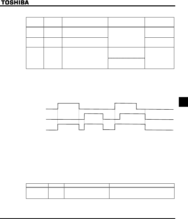
E6581381
F-11
6
(2) A signal is sent out when either of the two functions assigned is activated.
Terminal
symbol Title Function Adjustment range Default setting
RY - RC H Output terminal selection 1A 4 (Low-speed
detection signal)
RY - RC H Output terminal selection 1B
0~255
(⇒ See page K-17) 255 (Always ON)
0 : H and H
RY - RC H Output terminal logic selection
1 : H or H
0
+Two different functions can be assigned to terminals RY-RC.
+If parameter H is set to , a signal will be sent out when either of the two functions assigned is
activated.
Terminals RY-RC: Send out a signal when either of the functions set with H and H is activated.
+Timing chart
ON
OFF
ON
OFF
ON
OFF
H
H
RY-RC output
+Only one function can be assigned to terminals FLA-FLB-FLC at a time.
(3) Holding the output of signals in ON status
+If the conditions for activating the functions assigned to output terminals RY-RC agree with and as a result
the output of signals is put in ON status, the output of signals is held ON, even if the conditions change.
(Output terminal holding function)
+Assign input terminal function 62 to a contact input terminal available.
■Input terminal function
Function No. Code Function Action
62 HDRY Holding of RY-RC terminal
output
ON: Once turned on, RY-RC is held on.
OFF: The status of RY-RC changes in real
time according to conditions.
+Once output terminal RY-RC is turned on when the contact input terminal to which one of the above
functions (function 62) is assigned is ON, output terminal RY-RC is held ON.
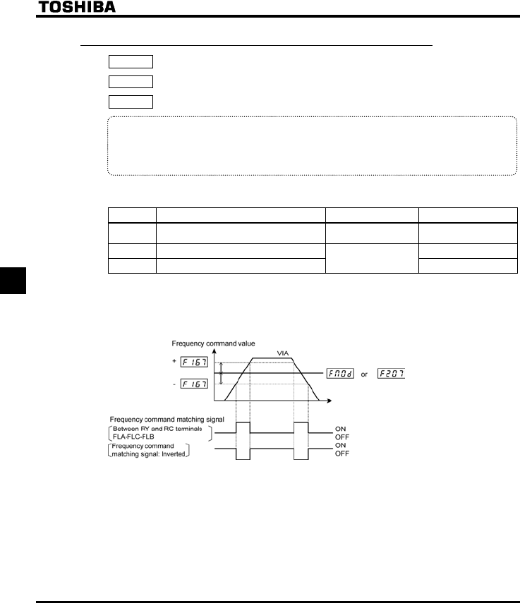
E6581381
F-12
6
6.3.5 Comparing the frequency command values
H : Frequency command agreement detection range
HOQF : Frequency setting mode selection 1
H : Frequency setting mode selection 2
•Function
If the frequency command value specified using HOQF (or H) almost agrees with the
frequency command value from the VIA and VIB terminal with an accuracy of ± H, an ON or
OFF signal will be sent out.
[Parameter setting]
Title Function Adjustment range Default setting
H Frequency command agreement detection
range 0.0 ∼ HJ (Hz) 2.5
HOQF Frequency setting mode selection 1 1
H Frequency setting mode selection 2 1-5 2
Note: When using VIA terminal, set H or H respectively to 52 or 53 to put out signals to RY-RC or
FLA-FLB-FLC.
When using VIB terminal, set H or H respectively to 60 or 61 to put out signals to RY-RC or
FLA-FLB-FLC.
Note: This function can be used, for example, to send out a signal indicating whether the amount of
processing and the amount of feedback agree with each other when the PID function is in use.
⇒ For an explanation of the PID function, see section 6.14.
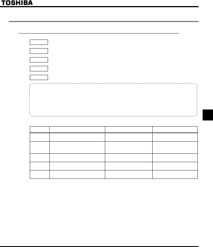
E6581381
F-13
6
6.4 Basic parameters 2
6.4.1 Switching motor characteristics via terminal input
H : Base frequency 2
H : Base frequency voltage 2
H : Torque boost 2
H : Motor electronic-thermal protection level 2
H : Stall prevention level 2
•Function
Use the above parameters to switch the operation of two motors with a single inverter and to select
motor V/F characteristics (two types) according to the particular needs or operation mode.
Note: The RV (V/F control mode selection) parameter is enabled only for motor1.
If motor 2 is selected, V/F control will be given constant torque characteristics.
[Parameter setting]
Title Function Adjustment range Default setting
H Base frequency 2 25.0-200.0 (Hz) 50.0 (WP type)
60.0 (WN type)
H Base frequency voltage 2 50-330 (V) : 200V class
50-660 (V) : 400V class
230 (WP/WN type)
400 (WP type)
460(WN type)
H Torque boost 2 0.0-30.0 (%) Depending on model
(⇒ See page K-14)
H Motor electronic-thermal
protection level 2 10-100 (%) / (A) 100
H Stall prevention level 2 10-110 (%) / (A),
111 : Disabled 110
E6581381
F-14
6
■Setting of switching terminals
The terminal for switching to motor 2 needs to be set, since this function is not assigned under the default
setting. Assign this function to an idle terminal.
The parameters to be switched depend on the particular identification number of the input terminal selection
function.
Input terminal function number
5
AD2
39
VF2
40
MOT2
61
OCS2
Parameters used and applicable parameters
OFF OFF OFF OFF Default setting: RV, XN, XNX, XD, VJT, CEE,
FGE, HU, H
ON OFF OFF OFF CEE → HU, FGE → H,
H → HU
OFF OFF OFF ON H → H
OFF ON OFF OFF RV → , XN → H, XNX → H,
XD → H, VJT → H
--ON-
RV → , XN → H, XNX → H,
XD → H, VJT → H,
H → H, CEE → HU,
FGE → H, H → HU
Note: The parameters XN, XNX, RV, H and H cannot be switched during operation. You need
to stop operation when switching them.
6.5 Frequency priority selection
6.5.1 Using a frequency command according to the particular
situation
HOQF : Frequency setting mode selection 1
H : Frequency priority selection
H : Speed setting mode selection 2
•Function
These parameters are used to switch between two types of frequency command signals.
•Setting by parameters
•Switching by frequency
•Switching via terminal board input

E6581381
F-15
6
[Parameter setting]
Title Function Adjustment range Default setting
HOQF Frequency setting mode selection 1
1: VIA
2: VIB
3: Operation panel
4: Serial communication
5: UP/DOWN from external
contact
1
H Frequency priority selection
0: HOQF(Switchable to H
by the input terminal)
1: HOQF (H for output
frequencies equal to or lower
than 1.0 Hz)
0
H Frequency setting mode selection 2
1: VIA
2: VIB
3: Operation panel
4: Serial communication
5: UP/DOWN from external
contact
2
1) External switching (Input terminal function 38 : FCHG enabled)
Frequency priority selection parameter H =
Switching between the command specified with HOQF and H can be made by entering a command
from a terminal board.
To do so, however, the frequency command forced switching function (input terminal function selection: 38)
needs to be set beforehand to an input terminal board.
If an OFF command is entered to the input terminal board: The command specified with HOQF will be
selected.
If an ON command is entered to the input terminal board: The command specified with H will be
selected.
2) Automatic switching by frequency command
Frequency priority selection parameter H =
The switching between the command specified with HOQF and H is done automatically according to
the frequency command entered.
If the frequency set with HOQF is above 1Hz: The command specified with HOQF will be selected.
If the frequency set with HOQF is 1Hz or less: The command specified with H will be selected.

E6581381
F-16
6
6.5.2 Setting frequency command characteristics
H : VIA input point 1 setting
H : VIA input point 1 frequency
H : VIA input point 2 setting
H : VIA input point 2 frequency
H : VIB input point 1 setting
H : VIB input point 1 frequency
H : VIB input point 2 setting
H : VIB input point 2 frequency
H : Communication command point 1 setting
H : Communication command point 1 frequency
H : Communication command point 2 setting
H : Communication command point 2 frequency
•Function
These parameters adjust the output frequency according to the externally applied analog signal (0-
10Vdc voltage, 4-20mAdc current) and the entered command for setting an external contact
frequency.
+To fine adjust the frequency command characteristics for VIA/VIB input, use the parameters H to
H. ⇒ See section 6.5.4.
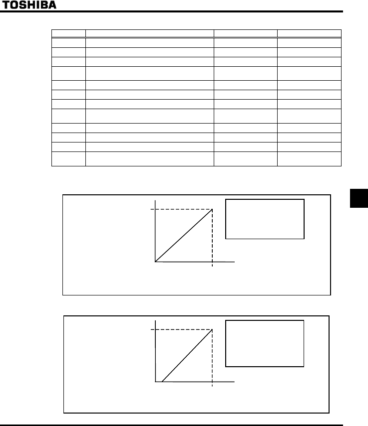
E6581381
F-17
6
[Parameter setting]
Title Function Adjustment range Default setting
H VIA input point 1 setting 0-100 (%) 0
H VIA input point 1 frequency 0.0-200.0 (Hz) 0.0
H VIA input point 2 setting 0-100 (%) 100
H VIA input point 2 frequency 0.0-200.0 (Hz) 50.0 (WP type)
60.0 (WN type)
H VIB input point 1 setting 0-100 (%) 0
H VIB input point 1 frequency 0.0-200.0 (Hz) 0.0
H VIB input point 2 setting 0-100 (%) 100
H VIB input point 2 frequency 0.0-200.0 (Hz) 50.0 (WP type)
60.0 (WN type)
H Communication command point 1 setting 0-100 (%) 0
H Communication command point 1 frequency 0.0-200.0 (Hz) 0.0
H Communication command point 2 setting 0-100 (%) 100
H Communication command point 2 frequency 0.0-200.0 (Hz) 50.0 (WP type)
60.0 (WN type)
Note: Don't set the same value between point 1 and point 2. If set the same falue, the GTT is displayed.
1) 0-10Vdc voltage input adjustment (VIA, VIB)
V
IA, VIB terminals ・The output frequenc
y
with
respect to the voltage input is
adjusted according to the
selected reference point.
・Gradient and bias can be set
easily.
H/H
100 (%)
10V voltage signal
H/H
0 ( Hz)
H/H
0 (%)
H/H
60 ( Hz )
0
Output
frequency
Frequenc
y
commnd
2) 4-20mAdc current input adjustment (VIA: VIA (SW3) slide switch in the I position)
V
IA terminal ・The output frequency with respect to
the current input is adjusted
according to the selected reference
point.
・Gradient and bias can be set easily.
・Set H to to create a current
input from 0 to 20mA.
H
100 (%)
20mA current signal
H
0 ( Hz)
H
20 (%)
4
H
60 ( Hz )
Output
frequency
Frequency commnd
E6581381
F-18
6
6.5.3 Setting of frequency with the input from an external
contact
H : External contact input - UP response time
H : External contact input - UP frequency steps
H : External contact input - DOWN response time
H : External contact input - DOWN frequency steps
H : Initial up/down frequency
H : Change of the initial up/down frequency
•Function
These parameters are used to set an output frequency by means of a signal from an external device.
Title Function Adjustment range Default setting
H External contact input - UP response
time 0.0 - 10.0 (s) 0.1
H External contact input - UP frequency
steps 0.0 - FH (Hz) 0.1
H External contact input - DOWN
response time 0.0 - 10.0 (s) 0.1
H External contact input - DOWN
frequency steps 0.0 - FH (Hz) 0.1
H Initial up/down frequency LL - UL (Hz) 0.0
H Change of the initial up/down
frequency
0: Not changed
1: Setting of H changed
when power is turned off
1
* These functions take effect when parameter HOQF (frequency setting mode selection 1) is set to or
parameter H (frequency setting mode selection 2) is set to is enabled.
■Adjustment with continuous signals (Parameter-setting example 1)
Set parameters as follows to adjust the output frequency up or down in proportion to the frequency
adjustment signal input time:
Panel frequency incremental gradient = H/H setting time
Panel frequency decremental gradient = H/H setting time
Set parameters as follows to adjust the output frequency up or down almost in synchronization with the
adjustment by the panel frequency command:
H = H = 1
(HJ/CEE (or H)) ≥ (H/H setting time)
(HJ/FGE (or H)) ≥ (H/H setting time)
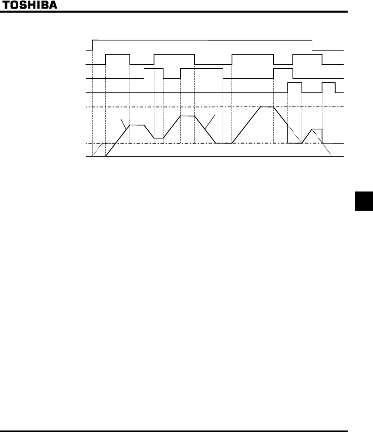
E6581381
F-19
6
<<Sample sequence diagram 1: Adjustment with continuous signals>>
The dotted line denotes the output frequency obtained by combining the slowdown speed and the panel
frequency adjustment speed.
Frequenc
y
0 Hz
Lower limit frequency
Gradient H/H
Gradient H/H
Upper limit frequency
Decrementing (DOWN) signal
Incrementing (UP) signal
RUN command
Set frequency clearing signal
Note: If the operation frequency is set to the lower limit frequency, it will increase from 0Hz when power is
turned on for the first time after the setting, and therefore the output frequency will not rise until the
operation frequency reaches the lower limit frequency. (Operation at the lower limit frequency)
In this case, the time required for the operation frequency to reach the lower limit frequency can be
shortened by setting HE to the lower limit frequency.
■Adjustment with pulse signals (Parameter-setting example 2)
Set parameters as follows to adjust the frequency in steps of one pulse:
H, H ≤ Pulse On time
H, H = Frequency obtained with each pulse
* The inverter does not respond to any pulses with an ON time shorter than that set with H or
H. 12ms or more of clearing signal is allowed.
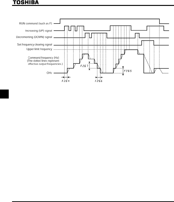
E6581381
F-20
6
<<Sample sequence diagram 2: Adjustment with pulse signals>>
■If two signals are impressed simultaneously
•If a clear single and an up or down signal are impressed simultaneously, priority will be given to the
clear signal.
•If up and down signals are impressed simultaneously, The frequency will change at the specified up
or down rate.
■About the setting of the initial up/down frequency
To adjust the frequency starting at a specified frequency other than 0.0 Hz (default initial frequency)
after turning on the inverter, specify the desired frequency using H (initial up/down frequency).
■About the change of the initial up/down frequency
To make the inverter automatically save the frequency immediately before it is turned off and start
operation at that frequency next time power is turned on, set H (change of initial up/down
frequency) to 1 (which changes the setting of H when power is turned off).
Keep in mind that the setting of H is changed each time power is turned off.
■Frequency adjustment range
The frequency can be set from 0.0Hz to HJ (Maximum frequency). The lower-limit frequency will be
set as soon as the set frequency clearing function (function number 43, 44) is entered from the input
terminal.
■Minimum unit of frequency adjustment
If H (Frequency free unit magnification) is set to 1.00, the output frequency can be adjusted in
steps of 0.01Hz.
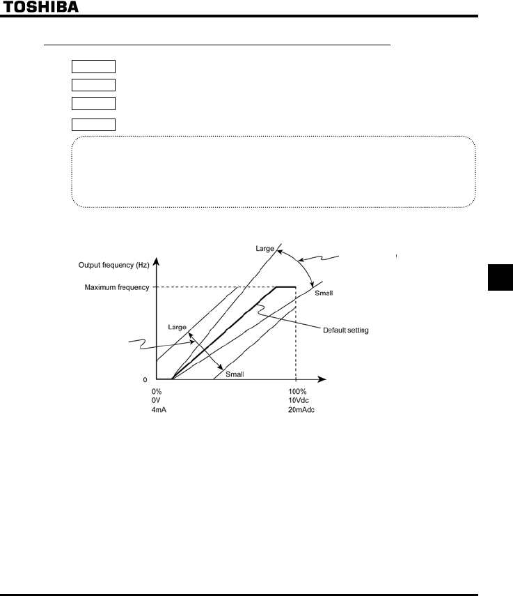
E6581381
F-21
6
6.5.4 Fine adjustment of frequency setting signal
H : VIA input bias
H : VIA input gain
H : VIB input bias
H : VIB input gain
•Function
These parameters are used to fine adjust the relation between the frequency setting signal input
through the analog input terminals VIA and VIB and the output frequency.
Use these parameters to make fine adjustments after making rough adjustments using the
parameters H to H.
The figure below shows the characteristic of the frequency setting signal input through the VIA and VIB
terminals and that of the output frequency.
Frequency setting signal (VIA, VIB input value)
* Bias adjustment of VIA and VIB input terminals (H and H)
To give leeway, the inverter is factory-adjusted by default so that it will not produce an output until a
certain amount of voltage is applied to the VIA and VIB input terminals. If you want to reduce the leeway,
set H or H to a larger value. Note that specifying a too large value may cause an output
frequency to be output, even though the operation frequency is 0 (zero) Hz.
* Gain adjustment of VIA and VIB input terminals (H and H)
The inverter is factory-adjusted by default so that the operation frequency can reach the maximum
frequency, even though the voltage and current to the VIA and VIB input terminals are below the
maximum levels. If you want to adjust the inverter so that it will output the maximum frequency at the
maximum voltage and current, set H or H to a smaller value. Note that specifying a too small
value may cause the operation frequency not to reach the maximum frequency, even though the
maximum voltage and current are applied.
H, H
H, H
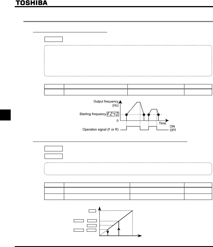
E6581381
F-22
6
6.6 Operation frequency
6.6.1 Starting frequency
H : Starting frequency setting
•Function
The frequency set with H is put out as soon as operation is started.
Use the H parameter when a delay in response of starting torque according to the
acceleration/deceleration time is probably affecting operation. Setting the starting frequency to a
value from 0.5 to 3Hz is recommended. The occurrence of an overcurrent can be suppressed by
setting this frequency below the rated slippage of the motor.
[Parameter setting]
Title Function Adjustment range Default setting
H Starting frequency setting 0.5-10.0 (Hz) 0.5
6.6.2 Run/stop control with frequency setting signals
H : Operation starting frequency
H : Operation starting frequency hysteresis
•Function
The Run/stop of operation can be controlled simply with frequency setting signals.
[Parameter setting]
Title Function Adjustment range Default setting
H Operation starting frequency 0.0-HJ (Hz) 0.0
H Operation starting frequency hysteresis 0.0-HJ (Hz) 0.0
0A B 100%
Frequency command value
H + H
H
H - H
HJ The inverter begins accelerating after
the frequency setting signal has reached
point B.
Deceleration begins when the frequency
setting signal decreases below point A.
Output frequency [Hz]
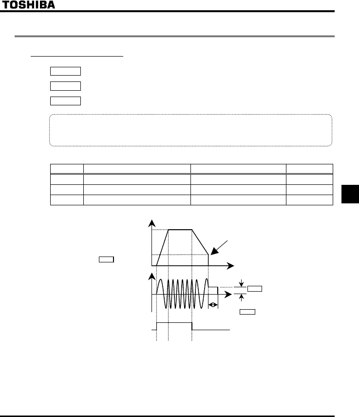
E6581381
F-23
6
6.7 DC braking
6.7.1 DC braking
H : DC braking starting frequency
H : DC braking current
H : DC braking time
•Function
A large braking torque can be obtained by applying a direct current to the motor. These parameters
set the direct current to be applied to the motor, the application time and the starting frequency.
[Parameter setting]
Title Function Adjustment range Default setting
H DC braking starting frequency 0.0-HJ (Hz) 0.0
H DC braking current 0-100 (%) / (A) 50
H DC braking time 0.0- 20.0 (sec) 1.0
Time [s]
DC braking starting frequency
H
DC braking current
H
DC braking time H
Output frequency [Hz]
DC braking
Operation signal (F or R) ON
OFF
Output current [A]
0
0
Set frequency
Note1: During DC braking, the overload protection sensitivity of the inverter increases. The DC braking
current may be adjusted automatically to prevent tripping.
Note 2: During DC braking, the carrier frequency is 6kHz irrespective of the setting of parameter H
(PWM carrier frequency).
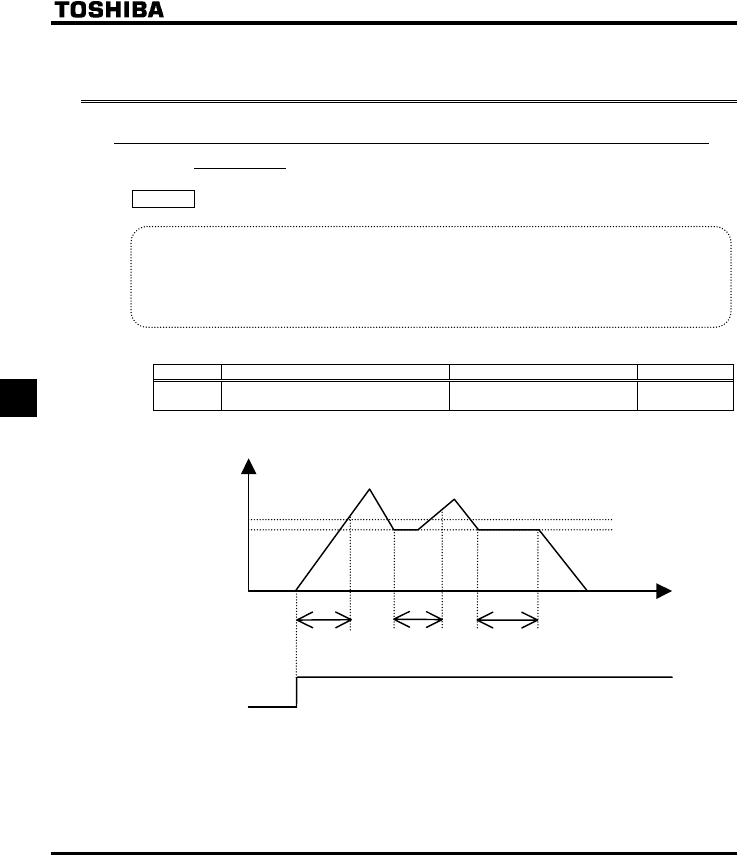
E6581381
F-24
6
6.8 Auto-stop in case of lower-limit frequency continuous
operation
6.8.1 Auto-stop in case of lower-limit frequency continuous
operation
H : Auto-stop in case of lower-limit frequency continuous operation
•Function
If operation is carried out continuously at a frequency command below the lower-limit frequency (NN) for
the period of time set with H, the inverter will automatically slow down the motor to a stop. At that
time, “NUVR” is displayed (alternately) on the operation panel.
This function will be canceled if a frequency command above the lower-limit frequency (NN) +0.2Hz.
[Parameter setting]
Title Function Adjustment range Default setting
H Auto-stop in case of lower-limit
frequency continuous operation time
0.0: Disabled
0.1-600.0 (s) 0.0
Note: This function is enabled even at the start of operation and during switching between forward and
reverse run.
Output frequency [Hz]
NN+0.2Hz
NN
Operation signal (F or R)
Time [s]
H
ON
OFF
HH
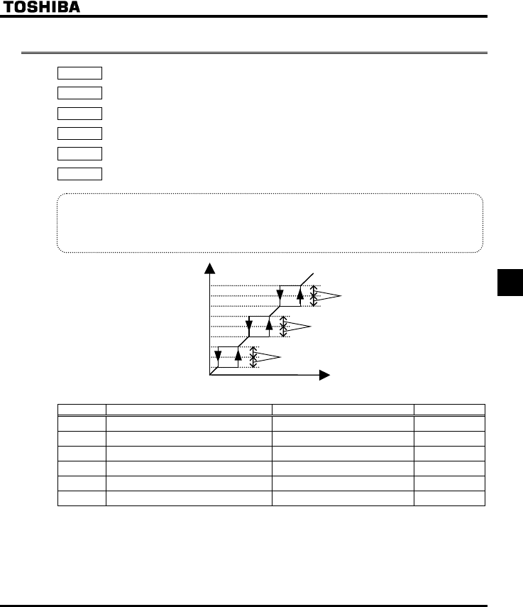
E6581381
F-25
6
6.9 Jump frequency - jumping resonant frequencies
H : Jump frequency 1
H : Jumping width 1
H : Jump frequency 2
H : Jumping width 2
H : Jump frequency 3
H : Jumping width 3
•Function
Resonance due to the natural frequency of the mechanical system can be avoided by jumping the
resonant frequency during operation. During jumping, hysteresis characteristics with respect to the jump
frequency are given to the motor.
Jumping width 1 (H)
Jumping width 2 (H)
Jumping width 3 (H)
Jump frequency 3 (H)
Jump frequency 1 (H)
Jump frequency 2 (H)
Output c ommand frequency
(Hz)
Frequency setting signal
0
[Parameter setting]
Title Function Adjustment range Default setting
H Jump frequency 1 0.0-HJ (Hz) 0.0
H Jumping width 1 0.0-30.0 (Hz) 0.0
H Jump frequency 2 0.0-HJ (Hz) 0.0
H Jumping width 2 0.0-30.0 (Hz) 0.0
H Jump frequency 3 0.0-HJ (Hz) 0.0
H Jumping width 3 0.0-30.0 (Hz) 0.0
+Do not set the jump parameters, if multiple jump frequency setting width overlap.
+During acceleration or deceleration, the jumping function is disabled for the operation frequency.
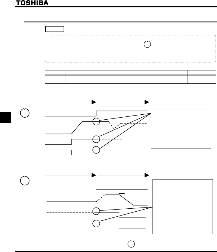
E6581381
F-26
6
6.10 Bumpless operation
H : Bumpless operation selection
•Function
When switching from Remote mode to Local mode using key, the status of start and stop, and
operating frequency at Remote mode are moved to Local mode.
By contraries, when switching from Local mode to Remote mode, they are not moved to Remote
mode.
[Parameter setting]
Title Function Adjustment range Default setting
H Bumpless operation selection 0: Disabled
1: Enabled 1
Example : Remote mode ( EOQF (Terminal board))
R
e
m
ote
m
ode
L
oca
l m
ode
ON
OFF
ON
OFF
ON
OFF
Key
Output
frequency
F-CC
Internal
operation
command
Local mode Remote mode
ON
OFF
ON
OFF
ON
OFF
Key
Output
frequency
F-CC
Internal
operation
command
Set frequency at
Remote mode
Setting frequency and start/stop
status are moved to Local mode
when switching from Remote
mode to Local mode.
Motor runs continuously like an
example.
When switching from Local
mode to Remote mode, setting
frequency and start/stop status
are determined by Remote
mode status.
The example shows the motor
runs continuously because the
Remote mode is “run” status.
To prevent from moving the setting frequency and start/stop status of Remote mode to Local mode,
the H is set to “”(Disabled). In this case, key is effective only while stopping.
LOC
REM
LOC
REM
LOC
REM
LOC
REM

E6581381
F-27
6
6.11 PWM carrier frequency
H : PWM carrier frequency
H : Random mode
H : Carrier frequency control mode selection
•Function
1) The H parameter allows the tone of the magnetic noise from the motor to be changed by
switching the PWM carrier frequency. This parameter is also effective in preventing the motor from
resonating with its load machine or its fan cover.
2) In addition, the H parameter reduces the electromagnetic noise generated by the inverter.
Reduce the carrier frequency to reduce electromagnetic noise. Note: Although the electromagnetic
noise level is reduced, the acoustic noise of the motor is increased.
3) The random mode reduces motor electromagnetic noise by changing the pattern of the reduced carrier
frequency.
[Parameter setting]
Title Function Adjustment range Default setting
H PWM carrier frequency 6.0-16.0 (kHz) (*)
12.0 or 8.0
Depending on model
(⇒ See page K-14)
H Random mode 0: Disabled, 1: Enabled 0
H Carrier frequency control mode
selection
0: Carrier frequency not reduced
automatically
1: Carrier frequency reduced
automatically
2: Carrier frequency not reduced
automatically
Support for 400V models
3: Carrier frequency reduced
automatically
Support for 400V models.
1
* Reduction of rated current will be required if the PWM carrier frequency is modified for each applicable motor
model. Refer to the following figure.
* When the PWM carrier frequency is set high, selecting “Carrier frequency not reduced automatically” causes
the inverter to be tripped more easily than selecting “Carrier frequency reduced automatically.”
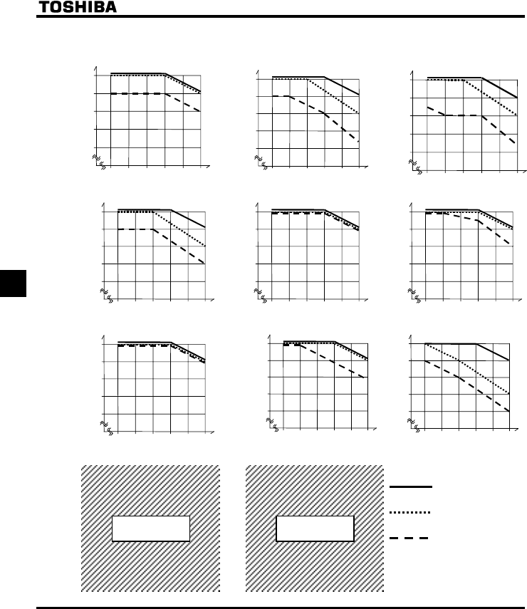
E6581381
F-28
6
Reduction of rated current.
[200V Class for IP20]
0.4-0.75kW 1.5kW 2.2kW
3.7kW 5.5kW 7.5kW
11kW 15kW 18.5kW
22kW 30kW
4
0degC
a
m
b
i
e
n
t
50degC ambient
60degC ambient
100%
90%
80%
70%
60%
6
Switching frequency (kHz)
Output current
8 10121416
100%
90%
80%
70%
60%
6
Switching frequency (kHz)
Output current
810121416
100%
90%
80%
70%
60%
6
Switching frequency (kHz)
Output current
810121416
100%
90%
80%
70%
60%
6
Switching frequency (kHz)
Output current
810121416
100%
90%
80%
70%
60%
6
Switching frequency (kHz)
Output current
810121416
100%
90%
80%
70%
60%
6
Switching frequency (kHz)
Output current
810121416
100%
90%
80%
70%
60%
6
Switching frequency (kHz)
Output current
8 10 121416
100%
90%
80%
70%
60%
6
Switching frequency (kHz)
Output current
810121416
100%
90%
80%
70%
60%
6
Switching frequency (kHz)
Output current
810 12 14 16
100%
90%
80%
70%
60%
6
Switching frequency (kHz)
Output current
810121416
100%
90%
80%
70%
60%
6
Switching frequency (kHz)
Output current
810121416
4kW
Coming soon Coming soon
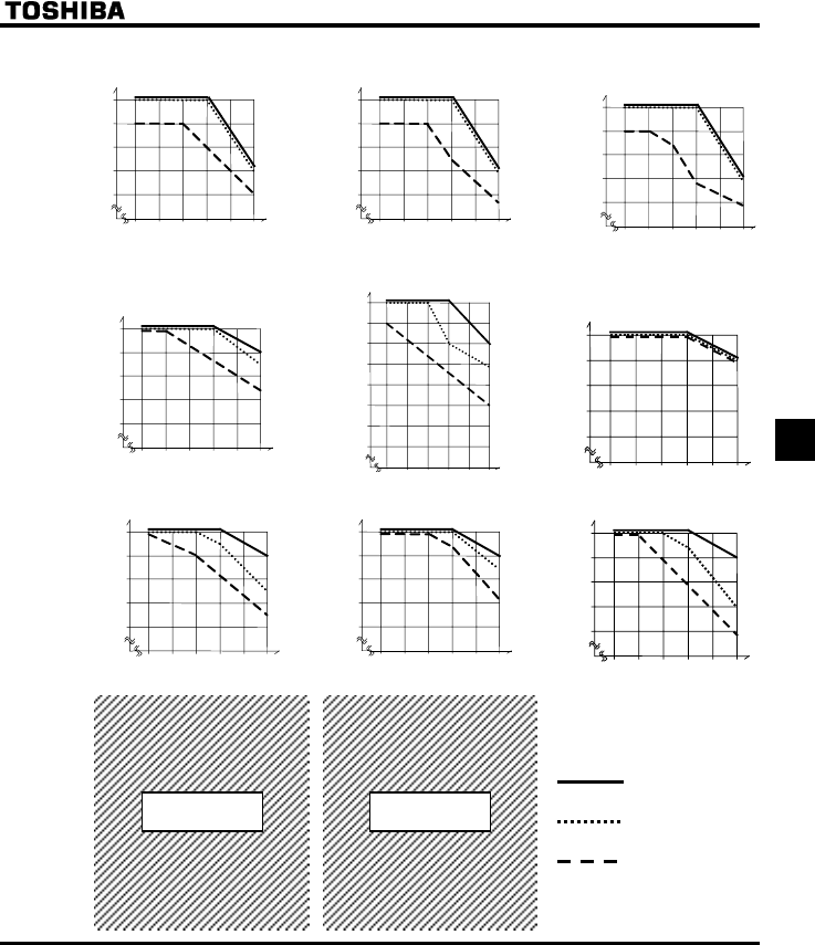
E6581381
F-29
6
[400V Class for IP20]
0.4-0.75kW 2.2kW
3.7kW
5.5kW
7.5kW
11kW 15kW 18.5kW
22kW 30kW
4
0degC
a
m
b
i
e
n
t
50degC ambient
60degC ambient
100%
90%
80%
70%
60%
6
Switching frequency (kHz)
Output current
810121416
100%
90%
80%
70%
60%
6
Switching frequency (kHz)
Output current
810121416
100%
90%
80%
70%
60%
6
Output current
50%
40%
30%
8 10 121416
Switching frequency (kHz)
100%
90%
80%
70%
60%
6
Switching frequency (kHz)
Output current
8 10121416
100%
90%
80%
70%
60%
6
Switching frequency (kHz)
Output current
810121416
100%
90%
80%
70%
60%
6
Switching frequency (kHz)
Output current
810121416
100%
90%
80%
70%
60%
6
Switching frequency (kHz)
Output current
810121416
100%
90%
80%
70%
60%
6
Output current
50%
40%
30%
8 10 121416
Switching frequency (kHz)
100%
90%
80%
70%
60%
6
Output current
50%
40%
30%
810121416
Switching frequency (kHz)
100%
90%
80%
70%
60%
6
Switching frequency (kHz)
Output current
810121416
4kW
1.5kW
100%
90%
80%
70%
60%
6
Switching frequency (kHz)
Output current
810121416
Coming soon Coming soon

E6581381
F-30
6
* The currents in the above figure are used as the basis to make calculations for inverter overload trip (QN).
* If H is set to or , QER trip will occur when the current increases and reaches the level above
which the carrier frequency is decreased automatically.
* Random control is exercised when the motor is operated in a low-frequency range where it produces
annoying magnetic noise.
If the carrier frequency (H) is set above 7.1 kHz, the random control function will not be performed,
because the level of motor magnetic noise is low at high frequencies.
* When the carrier frequency control mode selection (H) is set to or , the carrier frequency (H)
should be set preferably 6 kHz. Otherwise the output voltage may drop.
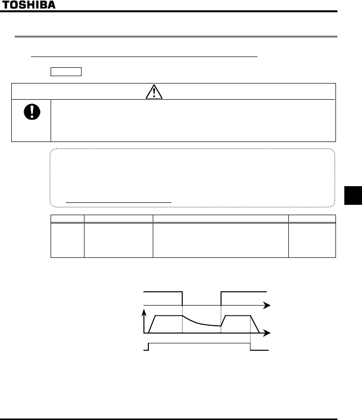
E6581381
F-31
6
6.12 Trip-less intensification
6.12.1 Auto-restart (Restart of coasting motor)
H : Auto-restart control selection
Caution
Mandatory
•Stand clear of motors and mechanical equipment
If the motor stops due to a momentary power failure, the equipment will start suddenly when power is
restored.
This could result in unexpected injury.
•Attach warnings about sudden restart after a momentary power failure on inverters, motors and
equipment for prevention of accidents in advance.
•Function
The H parameter detects the rotating speed and rotational direction of the motor during
coasting ing the event of momentary power failure, and then after power haas been restored, restarts
the motor smoothly (motor speed search function). This parameter also allows commercial power
operation to be switched to inverter operation without stopping the motor.
During operation, "TVT[" is displayed.
Title Function Adjustment range Default setting
H Auto-restart control
selection
0: Disabled
1: At auto-restart after momentary stop
2: When turning ST-CC on or off
3: At auto-restart or when turning ST-CC on or off
4: At start-up
0
* If the motor is restarted in retry mode, this function will operate, regardless of the setting of this parameter.
1) Auto-restart after momentary power failure (Auto-restart function)
Input voltage
Motor speed
F or R command ON
OFF
+Setting H to , (): This function operates after power has been restored following detection of an
undervoltage by the main circuits and control power.
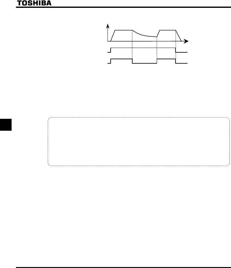
E6581381
F-32
6
2) Restarting motor during coasting (Motor speed search function)
Motor speed
F or R command ON
OFF
ST command ON
OFF
+Setting H to or : This function operates after the ST terminal connection has been OFF first and
then ON again.
Note: The terminal function ST needs to be assigned to an input terminal, using the parameters H to
H.
3) Motor speed search at starting
When H is set to , a motor speed search is performed each time operation is started.
This function is useful especially when the motor is not operated by the inverter but it is running because of
external force.
Warning!!
•At restart, it takes about 300 ms for the inverter to check to see the number of revolutions of the
motor.
For this reason, the start-up takes more time than usual.
•Use this function when operating a system with one motor connected to one inverter.
This function may not operate properly in a system configuration with multiple motors connected to
one inverter.
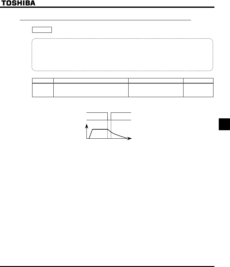
E6581381
F-33
6
6.12.2 Instantaneous power failure coast stop selection
H : Instantaneous power failure coast stop selection
•Function
Coast stop in the event of momentary power failure: If a momentary power failure occurs during
operation, the inverter coast stops forcibly. When operation is stopped, the message “UVQR” is
displayed (alternately) on the operation panel.
After the forced coast stop, the inverter remains static until you put off the operation command
momentarily.
[Parameter setting]
Title Function Adjustment range Default setting
H Instantaneous power failure coast stop
selection
0: Disabled
1: - (Do not select)
2: Coast stop
0
[If momentary power failure occurs]
Motor speed
Input voltage
E6581381
F-34
6
6.12.3 Retry function
H : Retry selection (Selecting the number of times)
Caution
Mandatory
•Do not go near the motor in alarm-stop status when the retry function is selected.
The motor may suddenly restart, which could result in injury.
•Take measures for safety, e.g. attach a cover to the motor, to prevent accidents if the motor suddenly
restarts.
•Function
This parameter resets the inverter automatically when the inverter gives an alarm. During the retry
mode, the motor speed search function operated automatically as required and thus allows smooth
motor restarting.
[Parameter setting]
Title Function Adjustment range Default setting
H Retry selection (number of
times) 0: Disabled, 1-10 times 0
The likely causes of tripping and the corresponding retry processes are listed below.
Cause of tripping Retry process Canceling conditions
Momentary power
failure
Overcurrent
Overvoltage
Overload
Overheating
Up to 10 times in succession
1st retry: About 1 sec after tripping
2nd retry: About 2 sec after tripping
3rd retry: About 3 sec after tripping
10th retry: About 10 sec after tripping
The retry function will be canceled at
once if tripping is caused by an unusual
event other than: momentary power
failure, overcurrent, overvoltage or
overload.
This function will also be canceled if
retrying is not successful within the
specified number of times.
+The retry function is disabled in the following unusual events:
• QEC : Arm overcurrent at start-up • GTT : Main unit RAM fault
• QEN : Overcurrent on the load side at start-up • GTT : Main unit ROM fault
• GRJQ : Output phase failure • GTT : CPU fault trip
• QJ : External thermal trip • GTT : Remote control error
• QV : Overtorque trip • GTT : Current detector fault
• G: External trip stop • GTT : Control circuit board format error
• WE : Small-current operation trip • GGR : EEPROM fault 1
• WR : Undervoltage trip (main circuit) • GGR : EEPROM fault 2
• GH : Ground fault trip • GGR : EEPROM fault 3
• GRJ : Input phase failure • GVP : Auto-tuning error
• GV[R : Inverter type error • G : VIA input detection error
• G : Main unit CPU communication error
• G : Excessive torque boost
• G : CPU fault 2
…

E6581381
F-35
6
+Protective operation detection relay signals (FLA, FLB, FLC terminal signals) are not sent during use of
the retry function. (Default setting)
+To allow a signal to be sent to the protective action detection relay (FLA, B and C terminals) even during
the retry process, assign the function 36 or 37 to H.
+A virtual cooling time is provided for overload tripping (QN,QN).
In this case, the retry function operates after the virtual cooling time and retry time.
+In the event of tripping caused by an overvoltage (QR - QR), the retry function will not be activated
until the voltage in the DC section comes down to a normal level.
+In the event of tripping caused by overheating (QJ), the retry function will not be activated until the
temperature in the inverter comes down low enough for it to restart operation.
+The retry function does not work even though H is activated in case of powering-up with H=
after trip.
+During retrying, the blinking display will alternate between TVT[ and the monitor display specified by
status monitor display mode selection parameter H.
+The number of retries will be cleared if the inverter is not tripped for the specified period of time after a
successful retry.
"A successful retry" means that the inverter output frequency reaches the command frequency without
causing the inverter to re-trip.
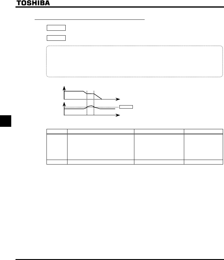
E6581381
F-36
6
6.12.4 Avoiding overvoltage tripping
H : Overvoltage limit operation
H : Overvoltage stall protection level
•Function
These parameters are used to keep the output frequency constant or increase it to prevent
overvoltage tripping in case the voltage in the DC section rises during deceleration or varying speed
operation. The deceleration time during overvoltage limit operation may increase above the
designated time.
Overvoltage limit operation level
DC Voltage
Output
Frequency
H :
Over-voltage stall protection level
[Parameter setting]
Title Function Adjustment range Default setting
H Overvoltage limit operation
(Slowdown stop mode selection)
0: Enabled
1: Disabled
2: Enabled (Quick
deceleration)
3: Enabled (Dynamic quick
deceleration)
2
H Overvoltage limit operation level 100-150% 140
+If H is set to (quick deceleration), the inverter will increase the voltage to the motor (over-
excitation control) to increase the amount of energy consumed by the motor when the voltage reaches the
overvoltage protection level, and therefore the motor can be decelerated more quickly than normal
deceleration.
+If H is set to (dynamic quick deceleration), the inverter will increase the voltage to the motor
(over-excitation control) to increase the amount of energy consumed by the motor as soon as the motor
begins to slow down, and therefore the motor can be decelerated still more quickly than quick
deceleration.
E6581381
F-37
6
6.12.5 Output voltage adjustment/Supply voltage correction
XNX : Base frequency voltage 1
H : Supply voltage correction (output voltage adjustment)
•Function
Base frequency voltage1
The H parameter adjusts the voltage corresponding to the base frequency 1 XN so that no
voltage exceeding the XNX set value is put out. (This function is enabled only when H is set
to either "0" or "1".)
Supply voltage correction
The H parameter maintains a constant V/F ratio, even when the input voltage decreases. The
torque during low-speed operation is prevented from decreasing.
Supply voltage correction: Maintains a constant V/F ratio, even when the input voltage fluctuates.
Limitation of output voltage: Limits the voltage at frequencies exceeding the base frequency. Applied when
operating a special motor with low induced voltage.
[Parameter setting]
Title Function Adjustment range Default setting
XNX Base frequency voltage1 50-330 (V) : 200V class
50-660 (V) : 400V class
230 (WP/WN type)
400 (WP type)
460 (WN type)
H Supply voltage correction
(limitation of output voltage)
0: Supply voltage uncorrected,
output voltage limited
1: Supply voltage corrected,
output voltage limited
2: Supply voltage uncorrected,
output voltage unlimited
3: Supply voltage corrected,
output voltage unlimited
2
+If H is set to "" or "", the output voltage will change in proportion to the input voltage.
+Even if the base frequency voltage (XNX parameter ) is set above the input voltage, the output voltage
will not exceed the input voltage.
+The rate of voltage to frequency can be adjusted according to the rated motor capacity. For example,
setting H to "" or "" prevents the output voltage from increasing, even if the input voltage
changes when operation frequency exceeds the base frequency.
+When the V/F control mode selection parameter (RV) is set to any number between and , the supply
voltage is corrected regardless of the setting of H.
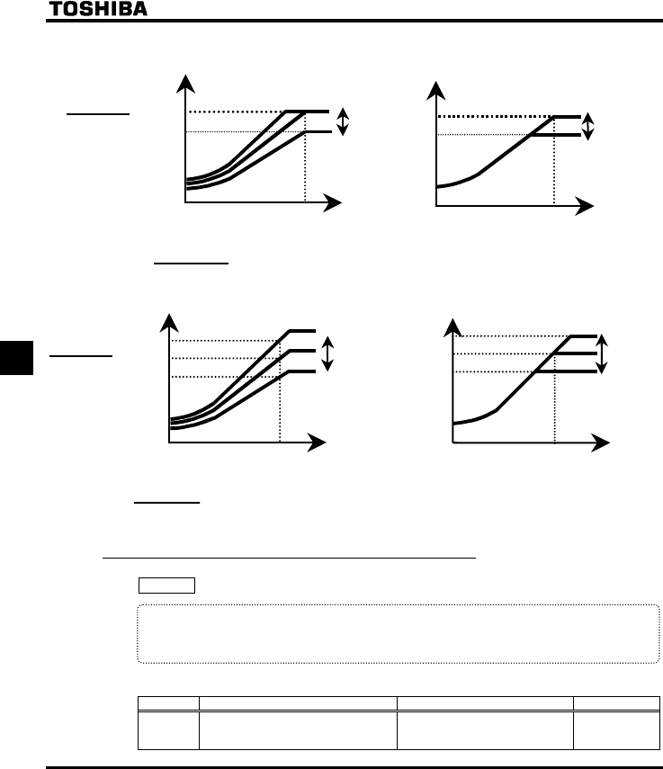
E6581381
F-38
6
[0: Supply voltage uncorrected, output voltage limited] [1: Supply voltage corrected, output voltage limited]
Output voltage
[V]
Input voltage
Output frequency XN
Hi
g
h
Low
0
×Input voltage
XNX
Rated voltage
>1 the output voltage can be prevented
from exceeding the input voltage.
XNX
Rated voltage
* The above applies when V/F control mode selection
parameter RV is set to "0" or "1".
[2: Supply voltage uncorrected, output voltage unlimited] [3: Supply voltage corrected, output voltage unlimited]
Output voltage
[V]
Input voltage
Output frequency XN
High
Low
0
×Input voltage
XNX
Rated voltage
>1 the output voltage can be prevented from
exceeding the input voltage.
XNX
Rated voltage
* The above applies when V/F control mode selection
parameter RV is set to "0" or "1".
6.12.6 Canceling the operation command
H : Reverse-run prohibition
•Function
This function prevents the motor from running in the forward or reverse direction when it receives the
wrong operation signal.
[Parameter setting]
Title Function Adjustment range Default setting
H Reverse-run prohibition
0: Forward/reverse run permitted
1: Reverse run prohibited
2: Forward run prohibited
0
XNX
Output voltage
[V]
Output frequency XN
0
Input voltage
High
Low
XNX
Output voltage
[V]
Output frequency XN
0
Input voltage
High
Low
* Even if XNX is set for an output voltage lower than the input
voltage, the output voltage will exceed the voltage adjusted
by XNX when the output frequency is higher than the base
frequency 1 XN.
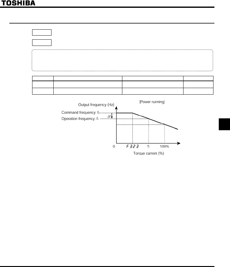
E6581381
F-39
6
6.13 Droop control
H : Droop gain
H : Droop insensitive torque band
•Function
The motor is allowed to “slip” according to the load torque current. Using these parameters, the
insensitive torque band and the gain can be adjusted.
[Parameter setting]
Title Function Adjustment range Default setting
H Droop gain 0-100% 0%
H Droop insensitive torque band 0-100% 10%

E6581381
F-40
6
+The droop control function refers to the function of operating the power-running motor at operating
frequency f1 (Hz) that is lower than command frequency f0 (Hz) by droop frequency ∆f (Hz) when the
torque current is T1 (%). (See the above figure.)
•The droop frequency ∆f can be calculated, using the following expression.
Droop frequency ∆f (Hz)=base frequency XN × H× (Torque current T1 - H)
•When the torque current is above the specified droop insensitive torque band (H), the frequency is
reduced during power running or increased during regenerative braking. The above figure shows an
example of the operating frequency during power running. During regenerative braking, control is
performed in such a way as to increase the frequency.
•The droop function is activated above the torque current set with H.
•The amount of droop frequency ∆f varies depending on the amount of torque current T1.
Note: If the base frequency XN exceeds 100Hz, count it as 100Hz.
Control is exercised between the starting frequency (H) and the maximum frequency (HJ).
[An example of calculation]
Parameter setting:Base frequency XN=60 (Hz), droop gain H=10 (%)
Droop insensitive torque band H=30 (%)
Droop frequency ∆f (Hz) and operating frequency f1 when command frequency f0 is 50 (Hz) and torque
current T1 is 100 (%) are as follows.
Droop frequency ∆f (Hz)=XN × H × (T1 - H)
=60 (Hz) × 10 (%) × (100 (%) - 30 (%))
=4.2 (Hz)
Operation frequency f1 (Hz) = f0 - ∆f = 50 (Hz) - 4.2 (Hz)=45.8 (Hz)
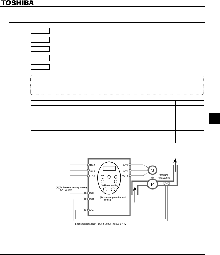
E6581381
F-41
6
6.14 Conducting PID control
H : PID control waiting time
H : PID control
H : Proportional gain
H : Integral gain
H : Differential gain
•Function
Using feedback signals (4 to 20mA, 0 to 10V) from a detector, process control can be exercised, for
example, to keep the airflow, amount of flow or pressure constant.
[Parameter setting]
Title Function Adjustment range Default setting
H PID control waiting time 0-2400 [s] 0
H PID control
0: Disabled
1: Enabled (Feedback: VIA)
2: Enabled (Feedback: VIB)
0
H Proportional gain 0.01-100.0 0.30
H Integral gain 0.01-100.0 0.20
H Differential gain 0.00-2.55 0.00
1) External connection
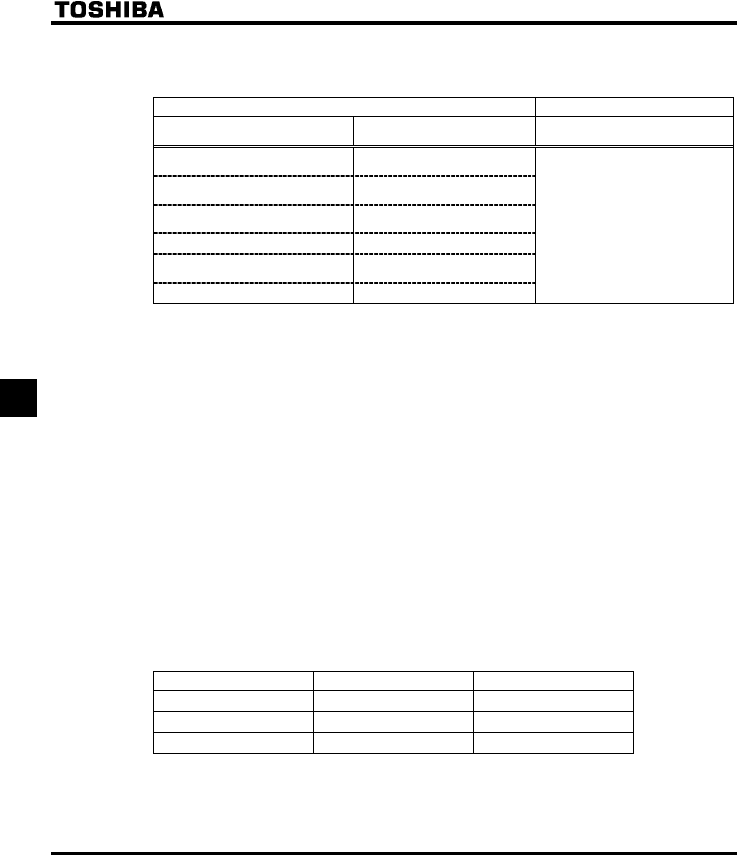
E6581381
F-42
6
2) Types of PID control interfaces
Process quantity input data (frequency) and feedback input data can be combined as follows for the PID
control of the VF-FS1:
Process quantity input data (frequency setting) Feedback input data
Setting method Frequency setting mode selection
HOQF / H
PID control
H
(1) External analog setting
VIA (DC: 4-20mA / 0-10V)
(2) External analog setting
VIB (DC: 0-10V)
(3) Panel input setting Internal
preset-speed setting
(4) Serial communication
(5) UP/DOWN from external
contact
(6) Internal preset-speed setting - (EOQF=0)
: External analog input
VIA (DC:4-20mA / DC:0-10V)
: External analog input
VIB (DC:0-10V)
Note 1: About the setting of HOQF and H: Do not select the same terminal that is used feedback
terminal (VIA or VIB).
Note 2: When using VIA terminal, set H or H respectively to 52 or 53 to put out signals to RY-RC
or FLA-FLB-FLC.
When using VIB terminal, set H or H respectively to 60 or 61 to put out signals to RY-RC
or FLA-FLB-FLC.
You can also specify a frequency agreement detection range (H).
⇒ For more information, see section 6.3.5.
3) Setting PID control
Set "" or "2" in the extended parameter H (PID control)
(1) Set parameters CEE(acceleration time), and FGE (deceleration time) to the system fitting values.
(2) To limit the output frequency, set parameters WN (upper limit frequency) and NN (lower limit
frequency). If process quantities are set from the operation panel, however, the process quantity setting
range will be limited by the settings of WN and NN.
4) Adjusting the PID control gain level
Adjust the PID control gain level according to the process quantities, the feedback signals and the object to
be controlled.
The following parameters are provided for gain adjustment:
Parameter Setting range Default setting
H (P-gain) 0.01-100.0 0.30
H (I-gain) 0.01-100.0 0.20
H (D-gain) 0.00-2.55 0.00
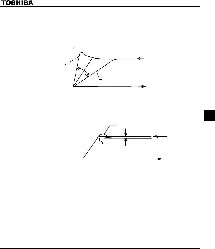
E6581381
F-43
6
H (P-gain adjustment parameter)
This parameter adjusts the proportional gain level during PID control. A correction value proportional to
the particular deviation (the difference between the set frequency and the feedback value) is obtained
by multiplying this deviation by the parameter setting.
A larger P-gain adjustment value gives faster response. Too large an adjustment value, however,
results in an unstable event such as hunting.
Slow response (H = Small gain)
Process quantity setting value
Time
Feedback amount
Fast respons e
(H = Large gain)
H (I-gain adjustment parameter)
This parameter adjusts the integral gain level during PID control. Any deviations remaining unremoved
during proportional action are cleared to zero (residual deviation offset function).
A larger I-gain adjustment value reduces residual deviations. Too large an adjustment value, however,
results in an unstable event such as hunting.
Residual deviation
Process quantity
setting value
Time
Feedback amount
(H = Large gain)
(H = Small gain)
+If one of input terminals is assigned input terminal function 65 (PID control integral value clear), integral
value is always 0 (zero) during the input terminal on.
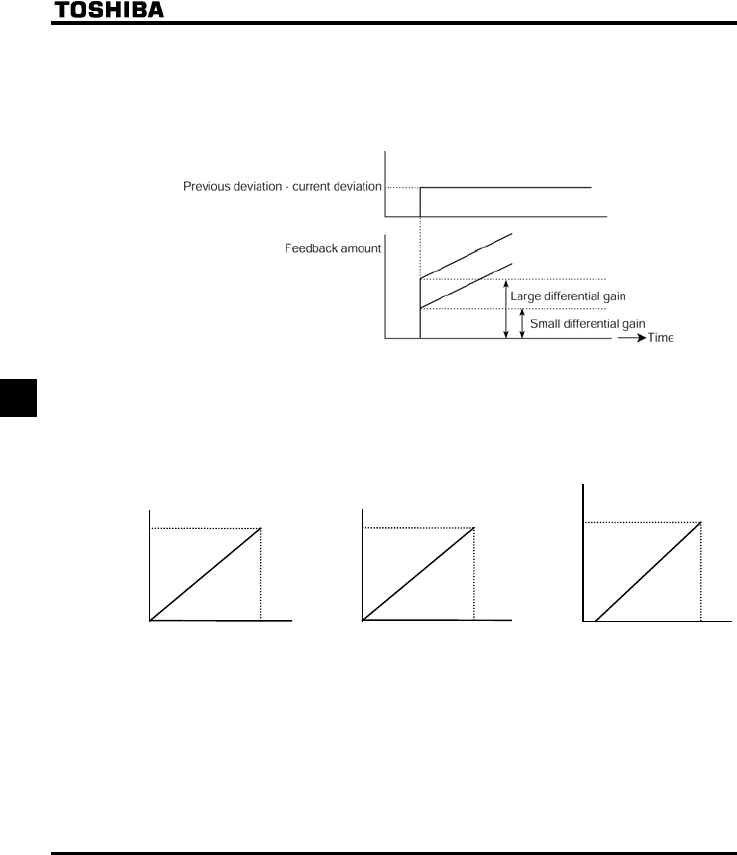
E6581381
F-44
6
H (D-gain adjustment parameter)
This parameter adjusts the differential gain level during PID control. This gain increases the speed of
response to a rapid change in deviation (difference between the frequency setting and the amount of
feedback).
Note that setting the gain more than necessary may cause great fluctuations in output frequency, and
thus operation to become unstable.
5) Adjusting analog command voltages
To use external analog setting (VIA or VIB) or feedback input (VIA or VIB), perform voltage-scaling
adjustments (input point setting) as required. ⇒ See section 6.5.2 for further details.
If the feedback input data is too small, voltage-scaling adjustment data can also be used for gain adjustment.
Example of VIB terminal setting Example of VIA terminal setting
(voltage input)
Example of VIA terminal setting
(current input)
H
(60Hz)
H
(0Hz)
0V
H
0%
10V
H
100%
VIB input value
Output frequency
H
(60Hz)
H
(0Hz)
0V
H
0%
10V
H
100%
VIA input value
Output frequency
H
(60Hz)
H
(0Hz) 4mA
H
20%
20mA
H
100%
VIA input value
Output frequenc
y
6) Setting the time elapsed before PID control starts
You can specify a waiting time for PID control to prevent the inverter from starting PID control before the
control system becomes stable, for example, after start-up.
The inverter ignores feedback input signals, carries out operation at the frequency determined by the amount
of processing for the period of time specified with H and enters the PID control mode after a lapse of
the specified time.

E6581381
F-45
6
6.15 Setting motor constants
6.15.1 Setting motor constants 1
H : Auto-tuning
H : Slip frequency gain
H : Autmatic torque boost value
H : Motor rated current
H : Motor no-load current
H : Motor rated speed
H : Speed control response coefficient
H : Speed control stable coefficient
To use vector control, automatic torque boost and automatic energy saving, motor constant setting (motor tuning)
is required. The following two methods are available to set motor constants.
1) Setting V/F control mode selection (RV) and auto-tuning (H) independently
2) Combining the V/F control mode selection (RV) and manual tuning
+Check to be sure that the setting of the parameter XN and that of the parameter XNX agree with the base
frequency (rated rotational speed) and base frequency voltage (rated voltage) of the motor to be operated,
respectively. If not, set the parameters correctly.
+When using the inverter to control the operation of a motor smaller in capacity by one grade or more, be
sure to set the motor rated current setting parameter (H) properly.
+Vector control may not operate properly if the motor capacity differs from the applicable rated capacity of the
inverter by more than two grades.
If current waveforms oscillate during operation, increase the speed control stability factor (H). This is
effective in suppressing oscillation.
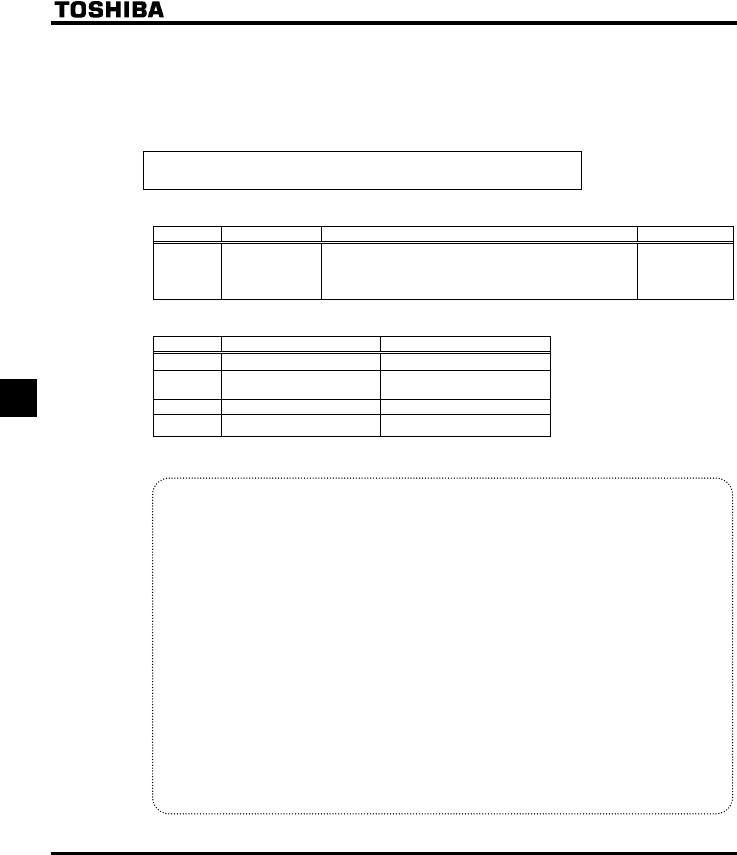
E6581381
F-46
6
[Selection 1: Setting vector control and auto-tuning independently]
This method sets energy-saving,sensorless vector control, automatic torque boost, and auto-tuning
independently.
Specify the control mode selection parameter (RV) and then set auto-tuning.
Set the auto-tuning parameter H to
(Auto-tuning enabled)
[Parameter setting]
Title Function Adjustment range Default setting
H Auto-tuning
0: Auto-tuning disabled (use of internal parameters)
1: Application of individual settings of H (after
execution: 0)
2: Auto-tuning enabled (after execution: 0)
0
(1) At least, set the following parameters, as specified on the nameplate of the motor.
Title Function Adjustment range
XN Base frequency 1 25.0-200.0 (Hz)
XNX Base frequency voltage 1 50-330 (V) : 200V class
50-660 (V) : 400V class
H Motor rated current 0.1-200.0 (A)
H Motor rated speed 100-15000 (min-1)
(2)Set H to to before the start of operation. Tuning is performed at the start of the motor.
+Precautions on auto-tuning
(1) Conduct auto-tuning only after the motor has been connected and operation completely stopped.
If auto-tuning is conducted immediately after operation stops, the presence of a residual voltage
may result in abnormal tuning.
(2) Voltage is applied to the motor during tuning even though it barely rotates. During tuning,
“CVP” is displayed on the operation panel.
(3) Tuning is performed when the motor starts for the first time after H is set to .
Tuning is usually completed within three seconds. If it is aborted, the motor will trip with the dis-
play of GVP and no constants will be set for that motor.
(4) High-speed motors, high-slip motors or other special motors cannot be auto-tuned. For these
motors, perform manual tuning using Selection 2 described below.
(5) The resulting insufficient motor torque during tuning could create a risk of machine stalling/falling.
(6) If auto-tuning is impossible or an "GVP" auto-tuning error is displayed, perform manual tuning
with Selection 2.
(7) If the inverter is tripped during auto-tuning because of an output phase failure (GRJQ), check if
the inverter is connected to the correctly. A check for output phase failures is made during auto-
tuning, regardless of the setting of the output phase failure detection mode selection parameter
(H).
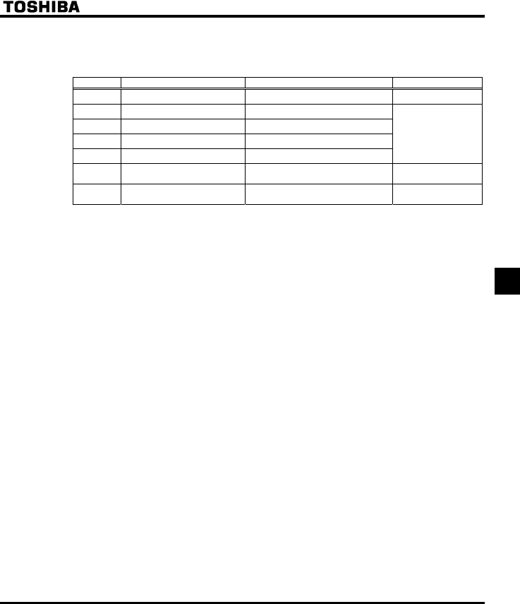
E6581381
F-47
6
[Selection 2: Setting vector control and manual tuning independently]
If an "GVP" tuning error is displayed during auto-tuning or when vector control characteristics are to be
improved, independent motor constants can be set.
Title Function Adjustment range Default setting
H Slip frequency gain 0-150 (%)50
H Automatic torque boost value 0.0-30.0 (%)
H Motor rated current 0.1-200.0 (A)
H Motor no-load current 10-100 (%)
H Motor rated rotational speed 100-15000 (min-1)
Depends on the
capacity
(⇒ See page K-14)
H Speed control response
coefficient 1-150 40
H Speed control stability
coefficient 1-100 20
Setting procedure Adjust the following parameters:
H: Set the compensation gain for the slipping of the motor. A higher slip frequency reduces motor
slipping correspondingly. After setting H, set H to adjust in detail.
H: Adjust the primary resistive component of the motor. Use the auto-tuning value.
H: Set the rated current of the motor. For the rated current, see the motor's nameplate or test report.
H: Set the ratio of the no-load current of the motor to the rated current. Enter the value in % that is
obtained by dividing the no-load current specified in the motor's test report by the rated current.
H: Set the rated rotational speed of the motor. For the rated current, see the motor's nameplate or test
report.
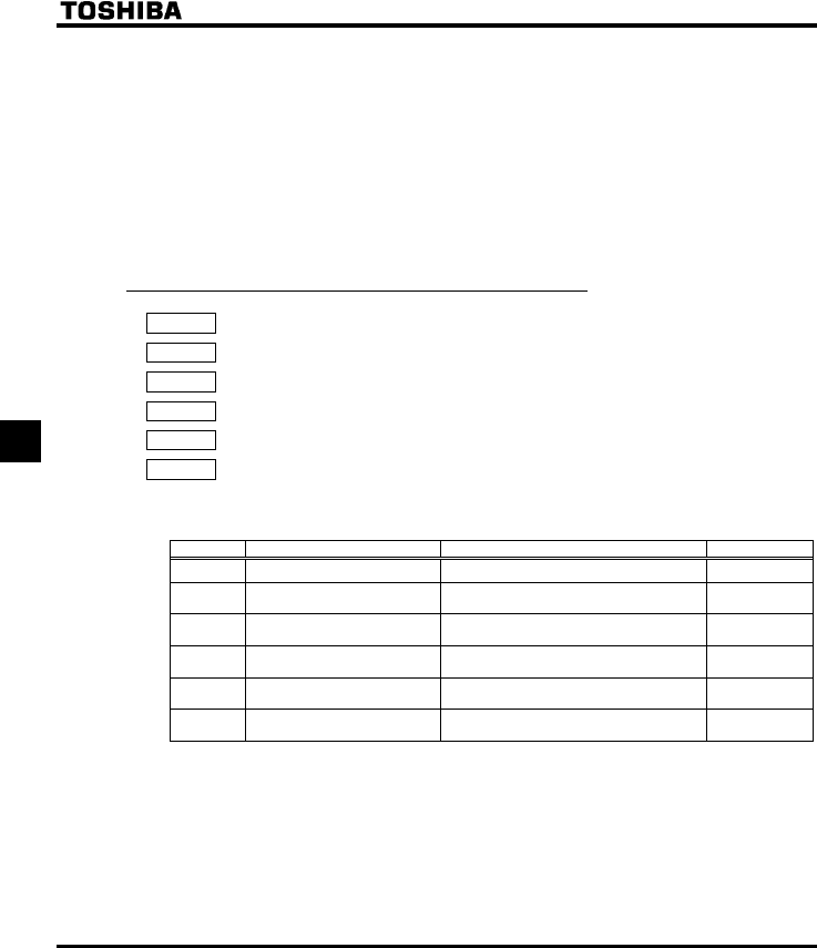
E6581381
F-48
6
H: Using this parameter along with H, adjust the speed of response to the frequency command.
H: Using this parameter along with H, adjust the speed of response to the frequency command.
* How to make adjustments according to the moment of inertia of the load
The moment of inertia of the load (including that of the motor shaft) was set at the factory on the
assumption that it would be three times as large as that of the motor shaft.
Adjust H, H with the ratio of inertia in case load inertia is different from three times
of the motor inertia.
When making the above adjustments, increase or decrease settings in steps of 10% or so while
checking how things change.
Note also that, depending on the settings of H and H, the frequency may exceed
the upper-limit frequency if the inverter is set so as to accelerate the load in the shortest
possible time.
6.15.2 Setting motor constants 2 (Details)
H : Exciting current coefficient
H : Stall prevention control coefficient 1
H : Stall prevention control coefficient 2
H : Motor adjustment coefficient
H : Maximam voltage adjustment coefficient
H : Waveform switching adjustment coefficient
* The following parameters enables you to make adjustments more finely.
Title Function Adjustment range Default setting
H Exciting current coefficient 100-130 (%) 100
H Stall prevention control
coefficient 1 10-250 100
H Stall prevention control
coefficient 2 50-150 100
H Motor adjustment coefficient 0-200 Depends on
the capacity
H Maximam voltage adjustment
coefficient 90-120 (%) 104
H Waveform switching
adjustment coefficient 0.1-14.0(kHz) 14.0
H:Used to fine adjust the magnetic field increase rate in low-speed range. To increase the torque in
low-speed range, specify a larger value for H. Note that this parameter should be adjusted
only when enough torque cannot be obtained, even though auto-tuning (H=) was made
after the setting of the parameters H through H. Note also that adjusting this
parameter may cause an increase in the no-load current in low-speed range. If the no-load current
exceeds the rated current, do not adjust this parameter.
H: Using this parameter along with H adjusts characteristics in a region in which the frequency
is above the base frequency (region where the field is weak).

E6581381
F-49
6
H: Using this parameter along with H adjusts characteristics in a region in which the frequency
is above the base frequency (region where the field is weak).
* How to make adjustments in a region (region where magnetic field is weak) above the base
frequency
If a heavy load is applied instantaneously (or transiently), the motor may stall before the load
current reaches the current set with the stall prevention level 1 parameter (H). In many
cases, this kind of stall can be avoided by gradually reducing the setting of H.
A drop in supply voltage may cause fluctuations of the load current or vibration of the motor. In
some cases, such phenomena can be eliminated by changing the setting of H to between
80 and 90. However, this may cause an increase in load current, so that it is also necessary to
adjust the setting of the electronic thermal protective level 1 parameter (VJT) properly
according to the motor capacity.
H: There is no need to adjust this parameter under normal conditions. (Do not change the setting,
unless otherwise instructed by Toshiba technical staff)
H: Specify a larger value for H to secure as high an output voltage as possible in a region
(region where magnetic field is weak) above the base frequency. Setting H to a larger value
may cause the motor to vibrate or gears to squeak. If such a phenomenon occurs, do not adjust
this parameter.
H: Specify a larger value for H if switching from a waveform to another results in a considerable
increase in vibration and noise in middle-speed range (region between the start frequency and the
base frequency). If no improvement can be made by specifying a larger value, do not adjust this
parameter.
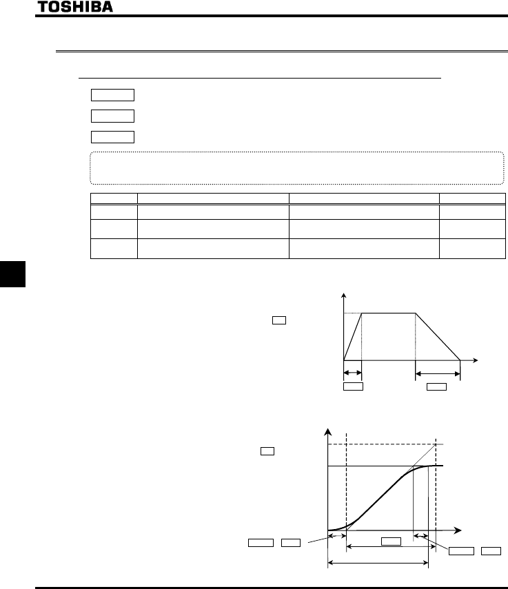
E6581381
F-50
6
6.16 Acceleration/deceleration time 2
6.16.1 Selecting an acceleration/deceleration pattern
H : Acceleration/deceleration 1 pattern
H : S-pattern lower-limit adjustment amount
H : S-pattern upper-limit adjustment amount
•Function
These parameters allow you to select an acceleration/deceleration pattern that suits the intended use.
Title Function Adjustment range Default setting
H Acceleration/ deceleration 1 pattern 0: Linear, 1: S-pattern 1, 2: S-pattern 2 0
H S-pattern lower-limit adjustment
amount 0-50% 10%
H S-pattern upper-limit adjustment
amount 0-50% 10%
1) Linear acceleration/deceleration
A general acceleration/
deceleration pattern.
This pattern can usually be
used.
2) S-pattern acceleration/deceleration 1
Select this pattern to
accelerate/decelerate the
motor rapidly to a high-speed
region with an output
frequency of 60Hz or more or
to minimize the shocks
applied during
acceleration/deceleration.
This pattern is suitable for
pneumatic transport
machines.
Output frequency
[Hz]
FGE
CEE
Maximum frequency
HJ
Time [s]
0
Actual acceleration time
Maximum frequency
HJ
Set frequency
H × CEE Time
[
s
]
Out
p
ut fre
q
uenc
y
[
Hz
]
0
H × CEE
CEE
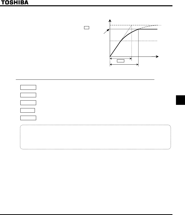
E6581381
F-51
6
3) S-pattern acceleration/deceleration
Select this pattern to obtain
slow acceleration in a
demagnetizing region with a
small motor acceleration
torque. This pattern is
suitable for high-speed
spindle operation.
6.16.2 Switching acceleration/deceleration time 1 and 2
H : Acceleration time 2
H : Deceleration time 2
H : Acceleration/deceleration 2 pattern
H: Selecting an acceleration/deceleration pattern
H : Acceleration/deceleration 1 and 2 switching frequency
•Function
Two acceleration times and two deceleration times can be specified individually. A method of selection or
switching can be selected from among the following:
1) Selection by means of parameters
2) Switching by changing frequencies
3) Switching by means of terminals
Maximum frequency
HJ
Set frequency
CEE
Actual acceleration time
Out
p
ut fre
q
uenc
y
[Hz]
Time [s]
0
Base frequency
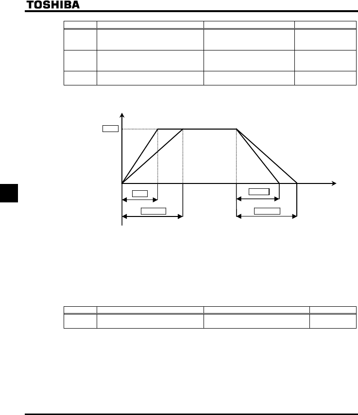
E6581381
F-52
6
Title Function Adjustment range Default setting
H Acceleration time 2 0.0-3200 [s]
Depends on the
capacity
(⇒ See page K-14)
H Deceleration time 2 0.0-3200 [s]
Depends on the
capacity
(⇒ See page K-14)
H Selecting an acceleration/deceleration
pattern
: Acc / dec 1
: Acc / dec 2 1
1) Selection using parameters
Time [s]
Output frequency [Hz]
FGE
CEE
HJ
H H
0
H=
H=
Acceleration/deceleration time 1 is initially set as the default. Acceleration/deceleration time 2 can be
selected by changing the setting of the H.
Enabled if EOQF= (panel input enabled)
2) Switching by frequencies - Switching the acceleration/deceleration time automatically at the frequency
setting of H.
Title Function Adjustment range Default setting
H Acceleration/deceleration 1 and 2
switching frequency 0.0-WN 0.0
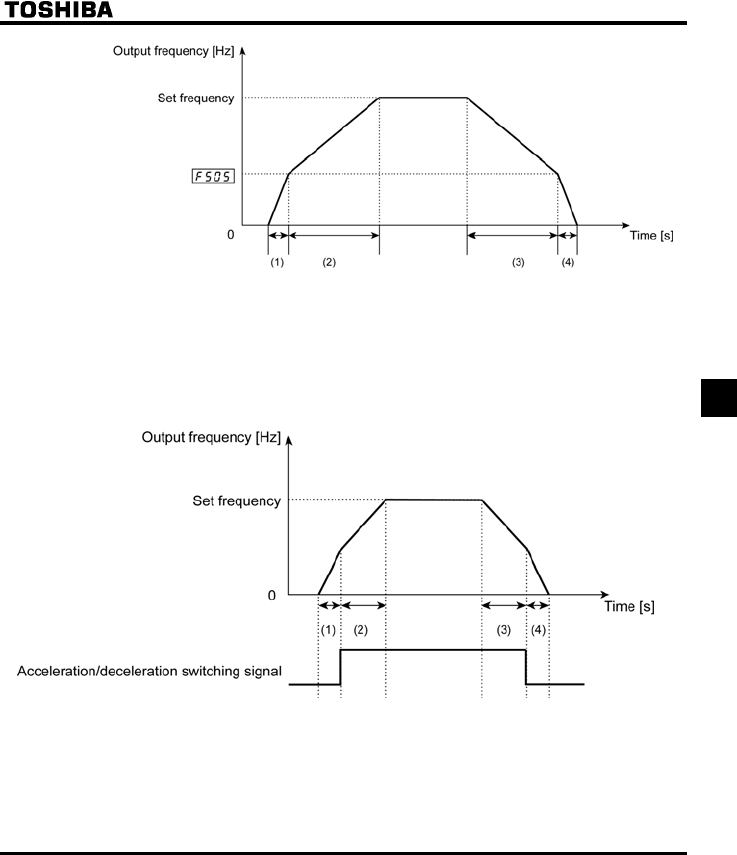
E6581381
F-53
6
(1) Acceleration at the gradient corresponding
to acceleration time CEE
(2) Acceleration at the gradient corresponding
to acceleration time H
(3) Deceleration at the gradient corresponding
to deceleration time H
(4) Deceleration at the gradient corresponding
to deceleration time FGE
3) Switching using external terminals - Switching the acceleration/deceleration time via external
terminals
(1) Acceleration at the gradient corresponding
to acceleration time CEE
(2) Acceleration at the gradient corresponding
to acceleration time H
(3) Deceleration at the gradient corresponding
to deceleration time H
(4) Deceleration at the gradient corresponding
to deceleration time FGE
E6581381
F-54
6
■How to set parameters
a) Operating method: Terminal input
Set the operation control mode selection EOQF to .
b) Use the RES terminal for switching. (Instead, other terminals may be used.)
RES: Acceleration/deceleration switching signal
Title Function Adjustment range Setting value
H Input terminal selection 3 (RES) 0-71
5 (the second
acceleration/deceleration
mode selection)
■Acceleration/ deceleration pattern
Acceleration/deceleration patterns can be selected individually, using the acceleration/deceleration 1, 2
and 3 parameters.
1) Linear acceleration/deceleration
2) S-pattern acceleration/deceleration 1
3) S-pattern acceleration/deceleration 2
Title Function Adjustment range Default setting
H Acceleration/ deceleration 1 pattern 0
H Acceleration/ deceleration 2 pattern
0: Linear
1: S-pattern 1
2: S-pattern 2 0
+Both the settings of the S-pattern lower-limit and upper-limit adjustment parameters (H and
H) are applied to any acceleration/deceleration S-pattern.
⇒ For an explanation of acceleration/deceleration patterns, see section 6.16.1.
6.17 Protection functions
6.17.1 Setting motor electronic thermal protection
VJT : Motor electronic thermal protection level 1
H : Motor electronic thermal protection level 2
H : Motor 150%-overload time limit
H: Motor electronic-thermal protection retention selection
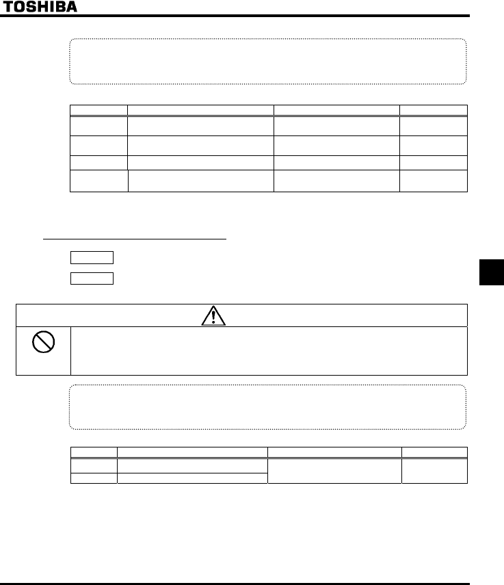
E6581381
F-55
6
•Function
This parameter allows selection of the appropriate electronic thermal protection characteristics
according to the particular rating and characteristics of the motor.
[Parameter setting]
Title Function Adjustment range Default setting
VJT Motor electronic thermal protection
level 1 10-100 (%) / (A) 100
H Motor electronic thermal protection
level 2 10-100 (%) / (A) 100
H Motor 150%-overload time limit 10-2400 (s) 300
H Motor electric-thermal protection
retention selection
0: Disabled
1: Enabled 0
⇒ For more details, see section 5.12.
Note: The 100% standard value is the rated output current indicated on the nameplate.
6.17.2 Setting current stall
H : Stall prevention level 1
H : Stall prevention level 2
Caution
Prohibited
•Do not set the stall prevention level (H) extremely low.
If the stall prevention level parameter (H) is set at or below the no-load current of the motor, the
stall preventive function will be always active and increase the frequency when it judges that
regenerative braking is taking place.
Do not set the stall prevention level parameter (H) below 30% under normal use conditions.
•Function
This parameter adjusts the output frequency by activating a current stall prevention function against a
current exceeding the H-specified level.
[Parameter setting]
Title Function Adjustment range Default setting
H Stall prevention level 1
H Stall prevention level 2
10-110 (%) / (A),
111: Deactivated 110
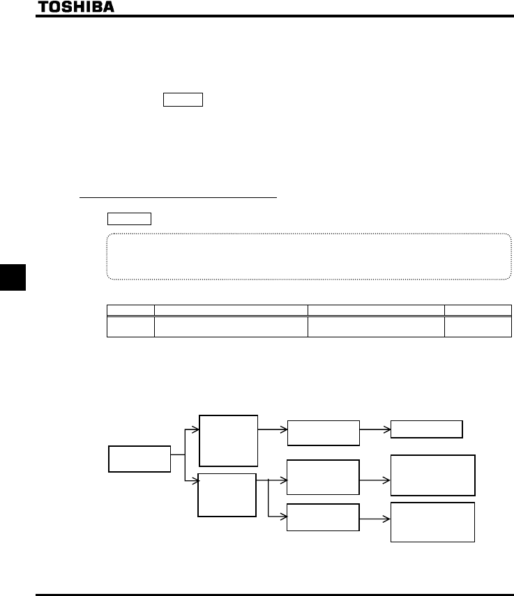
E6581381
F-56
6
[Display during operation of the stall prevention]
During an QE alarm status, (that is , when there is a current flow in excess of the stall prevention level),
the output frequency changes. At the same time, to the left of this value, "E" is displayed flashing on
and off.
Example of display
E
+The switching from H to H can be performed by entering a command through terminals.
⇒ For more details, see section 6.4.1.
Note: The 100% standard value is the rated output current indicated on the nameplate.
6.17.3 Inverter trip retention
H : Inverter trip retention selection
•Function
If the inverter trips, this parameter will retain the corresponding trip information. Trip information that
has thus been stored into memory can be displayed, even after power has been reset.
[Parameter setting]
Title Function Adjustment range Default setting
H Inverter trip retention selection 0: Canceled with the power off
1: Still retained with the power off 0
+The causes of up to four trips that occurred in the past can be displayed in status monitor mode.
+Data displayed in status monitor mode when the inverter is tripped is cleared when power is turned off.
Past trip records can be displayed.
+Trip records are retained even if power is turned off and turned back on during retry operation.
■Flow of operation when H=
Occurrence of a
trip
Reset the
inverter by
panel or
terminal
operation.
Turn power off,
then turn it back
on to reset the
inverter.
Completion of reset
If the cause of the
trip is not
eliminated
If the cause of the
trip is eliminated
Normal operation
The relay trips again.
・Display of the cause
・Failure signal FL
activated
Trip state is retained
・Display of the cause
・Failure signal FL not
activated
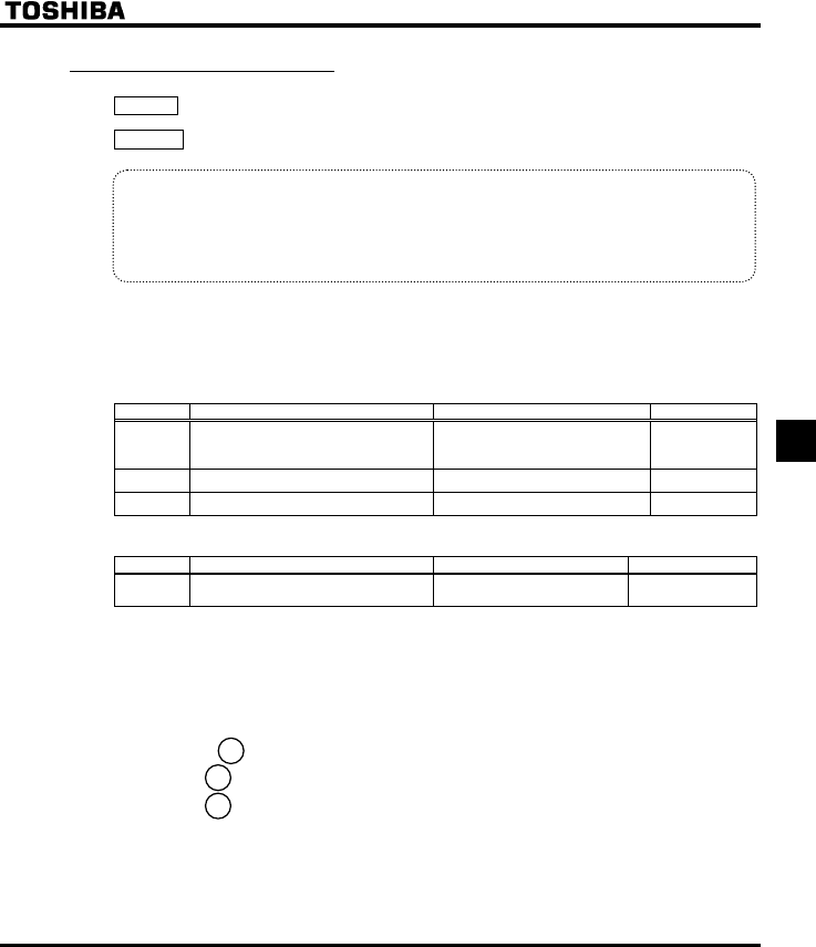
E6581381
F-57
6
6.17.4 Emergency stop
H: Emergency stop
H : Emergency DC braking time
•Function
These parameters allow you to specify how to stop operation using an external control device when
an external trip occurs. When operation is stopped, the trip G and the FL relay also are activated.
When setting H to (emergency DC braking), set also H (DC braking rate) and
H (emergency braking time)
1) External trip stop via terminals
The external trip stop function can be executed via the a-contact. Proceed as follows to assign an
external stopping terminal and select the stopping method:
[Parameter setting]
Title Function Adjustment range Default setting
H Emergency stop selection
0: Coast stop
1: Slowdown stop
2: Emergency DC braking
0
H Emergency DC braking time 0.0 ~ 20.0 [sec] 1.0
H DC braking current 0-100 (%) 50
(Example of terminal assignment): Assigning the trip stop function to the RES terminal
Title Function Adjustment range Setting value
H Input terminal selection 3 (RES) 0-71 11 (External trip
stop)
Note 1: Emergency stopping via the specified terminal is possible, even during panel operation.
Note 2: If DC braking is not needed to bring the motor to a stop under normal conditions, although H is
set to 2 (emergency DC braking), set the DC braking starting frequency (H) at 0.0 Hz.
2) Emergency stopping from the operation panel
Emergency stopping from the operation panel is possible
by pressing the key on the panel twice while the inverter is not in the panel control mode.
(1) Press the key................................"GQHH" will blink.
(2) Press the key once again Operation will come to a trip stop in accordance with the setting
of the H parameter.
After this, "G" will be displayed and a failure detection signal
generated (FL relay deactivated).
STOP
STOP
STOP

E6581381
F-58
6
6.17.5 Output phase failure detection
H : Output phase failure detection mode selection
•Function
This parameter detects inverter output Phase failure. If the Phase failure status persists for one
second or more, the tripping function and the FL relay will be activated. At the same time, a trip
information GRJQ will also be displayed.
Set H to to open the motor-inverter connection by switching commercial power operation to
inverter operation.
Detection errors may occur for special motors such as high-speed motors.
H=: No tripping (FL relay deactivated).
H=: With the power on, the phase failure detection is enabled only at the start of the first operation.
The inverter will trip if the Phase failure status persists for one second or more.
H=: The inverter checks for output phase failures each time it starts operation. The inverter will trip if
the Phase failure status persists for one second or more.
H=: The inverter checks for output phase failures during operation. The inverter will trip if the Phase
failure status persists for one second or more.
H=: The inverter checks for output phase failures at the start of and during operation. The inverter will
trip if the Phase failure status persists for one second or more.
H=: If it detects an all-phase failure, it will restart on completion of reconnection.
The inverter does not check for output phase failures when restarting after a momentary power
failure.
Note: A check for output phase failures is made during auto-tuning, regardless of the setting of this
parameter.
Title Function Adjustment range Default setting
H Output phase failure detection mode
selection
0: Disabled
1: At start-up (Only one time after
power is turned on)
2: At start-up (each time)
3: During operation
4: At start-up + during operation
5: Detection of cutoff on output
side
0
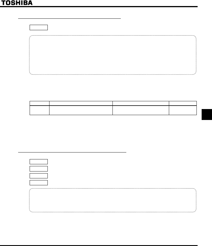
E6581381
F-59
6
6.17.6 Input phase failure detection
H : Input phase failure detection mode selection
•Function
This parameter detects inverter input Phase failure. If the abnormal voltage status of main circuit
capacitor persists for few minutes or more, the tripping function and the FL relay will be activated.
Therefore, input phase failures cannot always be detected. A trip information GRJK will be
displayed.
If the power capacity is larger than the inverter capacity (more than 200kVA or more than 10 times),
detection errors may occur. If this actually happens, install an input AC reactor.
H=: No tripping (Failure signal FL not activated)
H=: Phase failure detection is enabled during operation. The inverter will trip if the abnormal voltage
status of main circuit capacitor persists for ten minutes or more. (Failure signal FL activated)
Title Function Adjustment range Default setting
H Input phase failure detection mode
selection 0: Disabled, 1: Enabled 1
Note: Setting H to (input phase failure detection: disabled) may result in a breakage of the
capacitor in the inverter main circuit if operation is continued under a heavy load in spite of the
occurrence of an input phase failure.
6.17.7 Control mode for small current
H : Small current detection current hysteresis
H : Small current trip/alarm selection
H : Small current detection current
H : Small current detection time
•Function
The H parameter allows the inverter to be tripped if a current smaller than the H-
specified value flows for more than the H-specified time. When tripping is selected, enter the
detection time to tripping. Trip information is displayed as "WE".
H=: No tripping (Failure signal FL not activated).
A small current alarm can be put out by setting the output terminal function selection parameter.
H=: The inverter will trip (Failure signal FL activated) if a current below the current set with H
flows for the period of time specified with H.
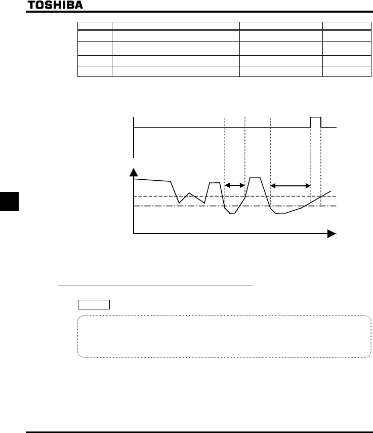
E6581381
F-60
6
Title Function Adjustment range Default setting
H Small current detection current hysteresis 1-20 (%) 10
H Small current trip/alarm selection 0: Alarm only
1: Tripping 0
H Small current detection current 0-100 (%) / (A) 0
H Small current detection time 0-255 [s] 0
<Example of operation>
Output terminal function: 24 (UC) Low current detection
H = (Alarm only)
Time [sec]
H+H
H
Output current (%)
Low current
signal output
H or less H
ON
OFF OFF
* When setting H to (Trip), trip after low current detection time setting of H. After tripping,
the low current signal remains ON.
6.17.8 Detection of output short-circuit
H : Detection of output short-circuit during start-up
•Function
This parameter detects inverter output short-circuit. It can be usually detected in the length of the
standard pulse. When operating low-impedance motor such as high-speed motor, however, the short-
time pulse should be selected.
H=: Detection is executed in the length of the standard pulse every time you start up the inverter.
H=: Detection is executed in the length of standard pulse only during the first start-up after putting on
the power or after resetting.
H=: Detection is executed with the short-time pulse every time you start up the inverter.
H=: Detection is executed with the short-time pulse only for the first time after putting power on or
after resetting.
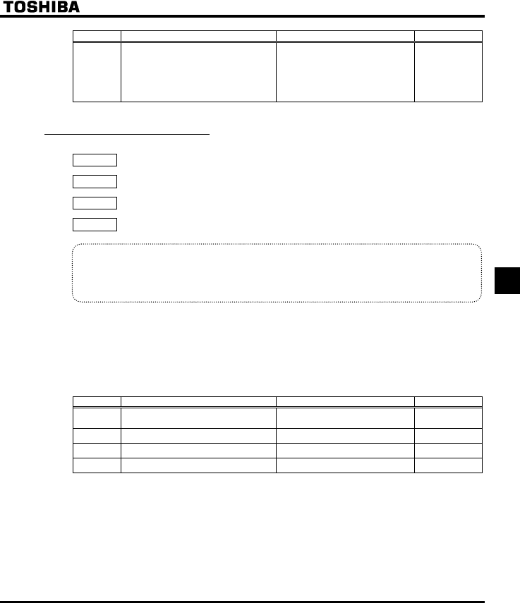
E6581381
F-61
6
Title Function Adjustment range Default setting
H Detection of output short-circuit during
start-up
0: Each time (standard pulse)
1: Only one time after power is
turned on (standard pulse)
2: Each time (short-time pulse)
3: Only one time after power is
turned on (short-time pulse)
0
6.17.9 Over-torque trip
H : Over-torque trip/alarm selection
H : Over-torque detection level
H : Over-torque detection time
H : Over-torque detection level hysteresis
•Function
Use the parameter to trip the inverter or to output the alarm if a torque currrent exceeding the
H-specified level flows for more than the H-specified time. Trip information is displayed
as "QV".
H=: .......... No tripping (FL relay deactivated).
An over-torque alarm can be put out by setting the output terminal function selection
parameter.
H=: .......... The inverter is tripped (FL relay activated) only after a torque current exceeding the
H-specified level has been detected for more than the H-specified time.
Title Function Adjustment range Default setting
H Over-torque trip/alarm selection 0: Alarm only
1: Tripping 0
H Over-torque detection level 0-200 (%) 130
H Over-torque detection time 0.0-10.0 [s] 0.5
H Over-torque detection level hysteresis 0-100 (%) 10
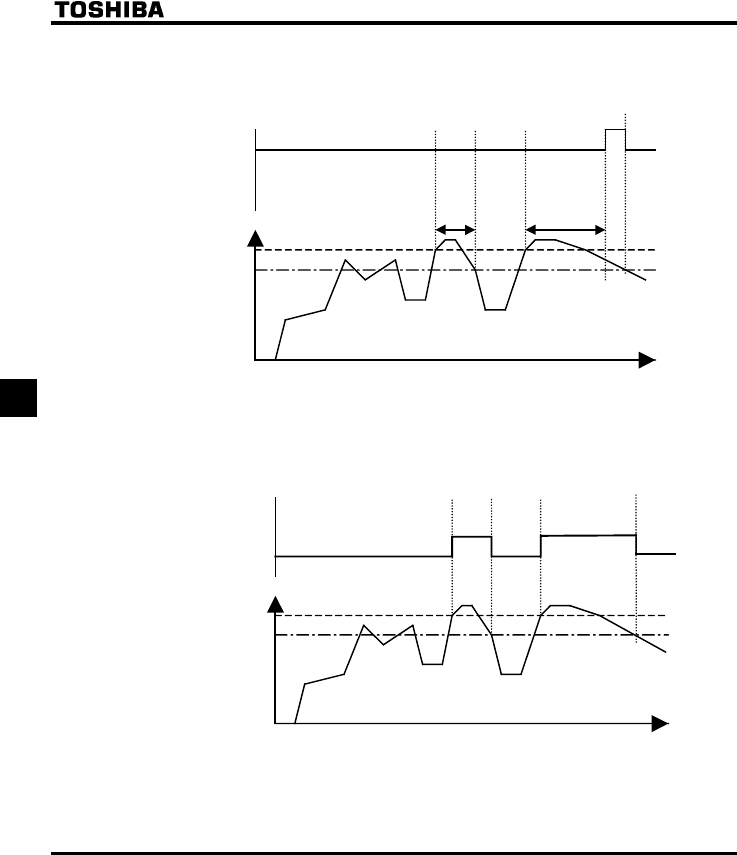
E6581381
F-62
6
<Example of operation>
1) Output terminal function: 12 (OT) Over-torque detection
H= (Alarm only)
Time [sec]
H−H
H
Torque current (%)
Over-torque
signal output
less than H H
ON
OFF OFF
When H = (tripping), the inverter will trip if over-torque lasts for the period of time set with
H. In such a case, the over-torque signal remains ON.
2) Output terminal function: 20 (POT) Over-torque detection pre-alarm
H
×
0.7−H
OFF ON OFF ON
H × 0.7
Torque current
(
%
)
Over-torque pre-alarm
Signal output
Time [sec]
E6581381
F-63
6
6.17.10 Cumulative operation time alarm setting
H : Cumulative operation time alarm setting
•Function
This parameter allows you to set the inverter so that it will put out an alarm signal after a lapse of the
cumulative operation time set with H.
* "0.1" displayed on the monitor refers to 10 hours, and therefore "1" denotes 100 hours.
Ex.: 38.5 displayed on the monitor = 3850 (hours)
Title Function Adjustment range Default setting
H Cumulative operation time
alarm setting 0.0-999.9 610.0
■Setting of output signal l
Ex.: When assigning the cumulative operation alarm signal output function to the RY-RC terminals
Title Function Adjustment range Setting value
H Output terminal selection 1A
(RY-RC) 0-255 42 (negative
logic 43)
6.17.11 Over-voltage stall protection level
H : Over-voltage stall protection level
⇒ For more details, see section 6.12.4.
E6581381
F-64
6
6.17.12 Undervoltage trip
H : Undervoltage trip/alarm selection
•Function
This parameter is used for selecting the control mode when an undervoltage is detected. Trip
information is displayed as "WR".
H=: The inverter is stopped. However, it is not tripped (Failure signal FL not activated).
The inverter is stopped when the voltage does not exceed 60 % or less of its rating.
H=: Inverter is stopped. It is also tripped (Failure signal FL activated), only after detection of a voltage
not exceeding 60% or less of its rating.
H=: Inverter is stopped. However, it is not tripped (Failure signal FL not activated). The inverter stop
(Failure signal FL not activated.), only after detection of a voltage not exceeding 50% of its rating.
Be sure to connect the input reactor.
Title Function Adjustment range Default setting
H Undervoltage trip/alarm
selection
0: Alarm only (detection level below 60%)
1: Tripping (detection level below 60%)
2: Alarm only (detection level below 50%,
input reactor needed)
0
E6581381
F-65
6
6.17.13 Trip at VIA low level input mode
H : Trip at VIA low level input mode
•Function
The inverter will trip if the VIA value remains below the specified value for about 0.3 seconds. In such
a case, "G" is displayed.
H=0: Disabled ........ The detection function is disabled.
H=1-100 ................ The inverter will trip if the VIA value remains below the specified value for about
0.3 seconds.
Title Function Adjustment range Default setting
H Trip at VIA low level input mode 0: Disabled
1-100% 0
Note : The VIA input value may be judged earlier to be abnormal, depending on the degree of deviation of
the analog data detected.
6.17.14 Parts replacement alarms
H : Annual average ambient temperature (For parts replacement alarms)
•Function
You can set the inverter so that it will calculate the remaining useful lives of the cooling fan, main
circuit capacitor and on-board capacitor from the ON time of the inverter, the operating time of the
motor, the output current (load factor) and the setting of H, and that it will display and send out
an alarm through output terminals when each component is approaching the time of replacement.
Title Function Adjustment range Default setting
H Annual average ambient temperature
(For parts replacement alarms)
1: -10 to +10°C
2: 11 to 20°C
3: 21 to 30°C
4: 31 to 40°C
5: 41 to 50°C
6: 51 to 60°C
3
+Display of part replacement alarm information
Part replacement alarm information (⇒ See page H-3) in the Status monitor mode allows you to check
on the time of replacement.
An example of display: O___
+Output of part replacement alarm signal
Assign the part replacement alarm function (function No. 44 or 45. ⇒ See page K-18) to an output terminal.
An example of setting: To assign the function to the RY-RC terminal
H=
Note 1: Using H enter the annual average temperature around the inverter. Be careful not to enter the
annual highest temperature
Note 2: Set H at the time of installation of the inverter, and do not change its setting after the start of
use. Changing the setting may cause parts replacement alarm calculation error.
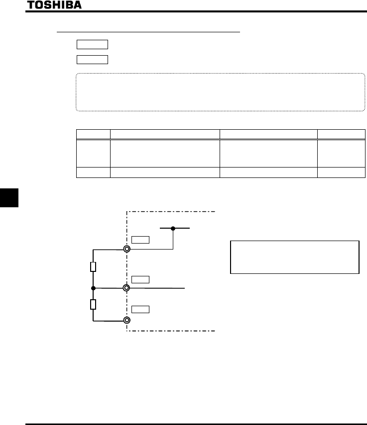
E6581381
F-66
6
6.17.15 Motor PTC thermal protection
H : PTC thermal selection
H : Resistor value for PTC detection
•Function
This function is used to protect motor from overheating using the signal of PTC built-in motor.
The trip display is “0Hz”.
[Parameter setting]
Title Function Adjustment range Default setting
H PTC thermal selection
0: Disabled
1: Enabled (trip mode)
2: Enabled (alarm mode)
0
H PTC detection resistor value 0 - 9999 3000
[Connection]
PP
P10V
VIB
CC
A
I [Volta
g
e]
Outer
resistor
PTC
Connect the resistor rated 1/4 watts 3.3k
ohm between terminal PP and VIB.

E6581381
F-67
6
6.17.16 Evasion from Overvoltage and Imput phase failure
H : Power supply compensation filter
H : Inhibitor filter
H : Inhibitor gain
•Function
When connecting input reactor or voltage regulator or the impedance of power supply is too big, the
following phenomenon are happened.
•Overvoltage trip (QR, QR, QR)
•Input phase failure (GRJ)
•Unusual noise of inverter
If these phenomenon is occurred, the following parameter should be adjusted.
[Parameter setting]
Title Function Adjustment range Default setting
H Power supply compensation filter 0-9999 (µs) 0
H Inhibitor filter 0-9999 (µs) 442
H Inhibitor gain 0.0– 300.0 (%) 100.0
At first, please set H as 442 and over. Next, set H and H as bigger value when no effect by
setting H as 1000 and over.
E6581381
F-68
6
6.18 Forced fire-speed control function
H : Forced fire-speed control function
H : Forced fire-speed setting frequency
•Function
Forced fire-speed control is used when operating the motor at the specified frequency in case of an
emergency. Two kind of operation are selectable by assignment of terminal board function.
(1)Input terminal function 52 (FORCE) : Input signal is kept to hold once signal is ON.
Motor runs at the speed set by the parameter “H”.
Motor does not stop in the event of the occurrence of a soft fault.
(2)Input terminal function 53 (FIRE) : Input signal is kept to hold once signal is ON.
Motor runs at the speed set by the parameter “H”.
Note: Both cases need to power off in order to stop.
[Parameter setting]
Title Function Adjustment range Default setting
H Forced fire-speed control selection 0: Disabled
1: Enabled 0
H Forced fire-speed setting frequency NNWN 50.0
When setting the parameter “H”, “HKTG” is displayed by pressing key. It can be set by
continuing the key for 2 seconds.
[Setting the forced operation input terminal (RES-CC)]
The control terminal “RES” (The default setting is “4” (reset function)) shall be assigned to “2” (Forced
operation function ).
Title Function Adjustment range Setting value
H Input terminal selection 3 (RES) 0 - 71
52
( Forced
operation 2 )
ENT
ENT
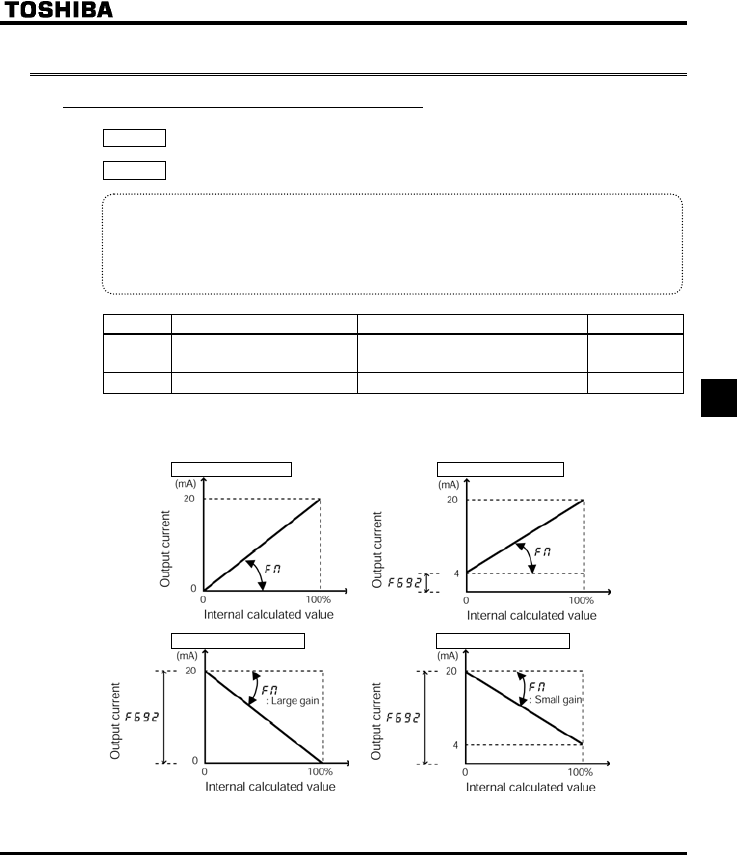
E6581381
F-69
6
6.19 Adjustment parameters
6.19.1 Calibration of analog outputs
H : Inclination characteristic of analog output
H : Bias of analog output
•Function
Output signals from FM terminals are analog voltage signals. Their standard setting range is from 0
to 7.5Vdc.
Using the FM (SW2) slide switch in the inverter, you can switch to 0-20mA output. Also, using these
parameters, you can calibrate the output to 4-20mAdc or 20-4mAdc.
Title Function Adjustment range Default setting
H Inclination characteristic of
analog output
0: Negative inclination (downward slope)
1: Positive inclination (upward slope) 1
H Bias of analog output 0-100 (%) 0
Note: To switch to 0-20mAdc (4-20mAdc), turn the FM (SW2) slide switch to the I position.
■Example of setting
H=1, H=0 H=1, H=20
H=0, H=100 H=0, H=100
+The analog output inclination can be adjusted using the parameter HO.
E6581381
F-70
6
6.20 Operation panel parameter
6.20.1 Prohibition of key operations and parameter settings
H : Prohibition of parameter change
H : Prohibition of frequency setting on the operation panel (FC)
H : Prohibition of panel local/remote operation (LOC/REM key)
H : Prohibition of panel operation (RUN/STOP keys)
H : Prohibition of panel emergency stop operation
H : Prohibition of panel reset operation
•Function
These parameters allow you to prohibit the operation of the RUN and STOP keys on the operation
panel and the change of parameters. Using these parameters, you can also prohibit various key
operations.
[Parameter setting]
Title Function Adjustment range Default setting
H Prohibition of parameter change 0: Permitted, 1: Prohibited 0
H Prohibition of frequency setting on the
operation panel (FC) 0: Permitted, 1: Prohibited 0
H Prohibition of panel local/remote
operation (LOC/REM key) 0: Permitted, 1: Prohibited 0
H Prohibition of panel operation
(RUN/STOP keys) 0: Permitted, 1: Prohibited 0
H Prohibition of panel emergency stop
operation 0: Permitted, 1: Prohibited 0
H Prohibition of panel reset operation 0: Permitted, 1: Prohibited 0
■Resetting method
Only the H parameter is designed so that its setting can be modified even if 1 (prohibited) is selected.
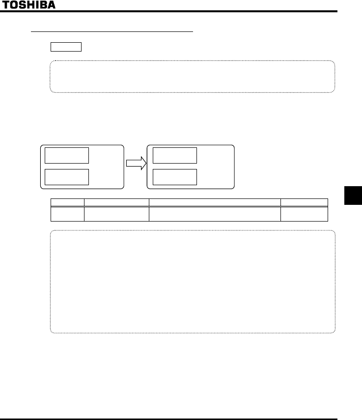
E6581381
F-71
6
6.20.2 Changing the unit to A / V
H :Current / voltage unit
•Function
These parameters are used to change the unit of monitor display.
% ⇔ A (ampere) / V (volt)
■Example of setting
During the operation of the VFFS1-2037PM (rated current: 17.5A) at the rated load (100% load), units are
displayed as follows:
1) Display in percentage terms 2) Display in amperes/volts
[
E.E
[
Output current:
17.5A
DC voltage:
200V (value
converted into
AC)
DC voltage:
100%
Output current:
100%
%
%
Title Function Adjustment range Default setting
H Current/voltage
display mode
0: %
1: A (ampere)/V (volt) 0
*The H converts the following parameter settings:
•A display Current monitor display
Motor electronic-thermal protection level 1 and 2
VJT, H
DC braking current H
Stall prevention level 1 and 2 H, H
Small current detection current H
Step-out detection current level H
(for PM motors)
•V display Voltage monitor display
Note: Base frequency voltage 1 and 2 I(XNX, H)s always displayed in the unit of V.
E6581381
F-72
6
6.20.3 Displaying the rotational speed of the motor or the line
speed
H : Frequency free unit magnification
H : Inclination characteristic of free unit display
H : Bias of free unit display
•Function
The frequency or any other item displayed on the monitor can be converted freely into the rotational
speed of the motor, the operating speed of the load, and so on.
The value obtained by multiplying the displayed frequency by the H-set value will be displayed as
follows:
Value displayed = Monitor-displayed or parameter-set frequency × H
1) Displaying the motor speed
To switch the display mode from 60Hz (default setting) to 1800min-1 (the rotating speed of the 4P motor)
H=
×.=
H=.
Hz
2) Displaying the speed of the loading unit
To switch the display mode from 60Hz (default setting) to 6m/min-1 (the speed of the conveyer)
H=. H=.
×.=.
Hz
Note: This parameter displays the inverter output frequency as the value obtained by multiplying it by a
positive number. This does not mean that the actual motor speed or line speed are indicated
with accuracy.
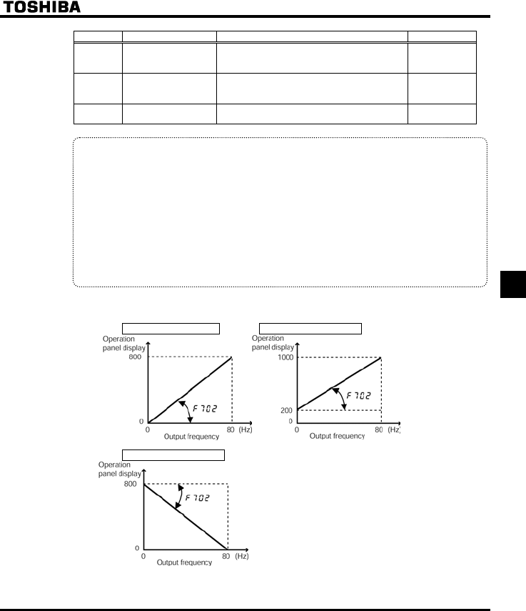
E6581381
F-73
6
Title Function Adjustment range Default setting
H Frequency free unit
magnification
0.00: Free unit display disabled (display of
frequency)
0.01-200.0
0.00
H
Inclination
characteristic of free
unit display
0: Negative inclination (downward slope)
1: Positive inclination (upward slope) 1
H Bias of free unit
display 0.00-HJ 0.00
*The H to H converts the following parameter settings:
•Free unit Frequency monitor display Operation frequency command, Operation
frequency, PID feedback, Frequency command
value (PID-computed), Operation frequency
command at trip
Frequency-related parameters HJ, WN, NN, UT - UT,
H, H, H, H,
H, H, H, H,
H, H, H, H,
H, H, H, H-H,
H, H, H, H
■An example of setting when HJ is 80 and H is 10.00
H=1, H=0.00 H=1, H=20.00
H=0, H=80.00
E6581381
F-74
6
6.20.4
Changing the steps in which the value displayed changes
H : Free step 1 (pressing a panel key once)
H : Free step 2 (panel display)
•Function
These parameters are used to specify steps in which the command value or standard monitor output
frequency displayed on the panel changes each time you press the key to set a frequency
on the operation panel.
Note 1: The settings of these parameters have no effect when the free unit selection (H) is enabled.
Note 2: If you press the key on the panel repeatedly to increase the frequency while H is set to
any value other than 0, the “HI” alarm will appear immediately before the frequency exceeds the HJ
(maximum frequency) and the frequency will stop increasing. Similarly, if you press the key on
the panel repeatedly to decrease the frequency, the “LO” alarm will appear immediately before the
frequency decreases below the NN (lower-limit frequency) and the frequency will stop decreasing.
■When H is not 0.00, and H is not 0 (disabled)
Under normal conditions, the frequency command value from the operation panel increases in steps of 0.1
Hz each time you press the key. If H is not 0.00, the frequency command value will increase by
the value with H each time you press the key. Similarly, it will decrease by the value set with
H each time you press the key.
In this case, the output frequency displayed in standard monitor mode changes in steps of 0.1 Hz, as usual.
■When H is not 0.00, and H is not 0 (disabled)
The value displayed on the panel also can also be changed in steps.
Output frequency displayed in standard monitor mode = Internal output frequency ×
Title Function Adjustment range Default setting
H Free step 1 (pressing a panel key
once)
0.00: Disabled
0.01-HJ (Hz) 0.00
H Free step 2 (panel display) 0: Disabled
1-255 0
■Example of setting 1
When H=10.00 (Hz):
The frequency (HE) set on the operation panel changes in steps of 10.0 Hz: 0.0 → 10.0 → 20.0 → ... 60.0
(Hz), each time you press the key. This function comes in very handy when operating the load at limited
frequencies that change in steps of 1Hz, 5Hz, 10Hz, and so on.
H
H
E6581381
F-75
6
■Example of setting 2
When H=1.00 (Hz), and H=1:
Each time you press the key, the frequency setting HE changes in steps of 1Hz: 0→ 1 → 2 → ... → 60
(Hz) and also the value displayed on the operation panel changes in steps of 1. Use these settings to hide
decimal fractions and also the value displayed on the operation panel changes in steps of 1. Use these
settings to hide decimal fractions.
6.20.5 Changing the item displayed by default
H : Standard monitor display selection
•Function
This parameter specifies display format while power is on.
■Changing the display format while power is on
When the power is on, the standard monitor mode displays the operation frequency (default setting) in the
format of "" or "QHH". This format can be changed to any other monitor display format by setting
H. This new format, however, will not display an assigned prefix such as V or E.
[Parameter setting]
Title Function Adjustment range Default setting
H Standard monitor display
selection
0: Operation frequency (Hz/free unit/step)
1: Frequency command (Hz/free unit/step)
2: Output current (%/A)
3: Inverter rated current (A)
4: Inverter load factor (%)
5: Output power (kW)
6: Frequency command after PID control
(Hz/free unit/step)
7: Optional item specified from an external
control unit
8: Output speed
9: Communication counter
10: Normal state communication counter
0
+For more information on the H option “,” refer to “Communications Function Instruction
Manual.”
E6581381
F-76
6
6.20.6 Selection of operation panel stop pattern
H : Selection of operation panel stop pattern
•Function
This parameter are used to select a mode in which the motor started by pressing the key on the
operation panel is stopped when the key is pressed.
1) Slowdown stop
The motor slows down to a stop in the deceleration time set with FGE (or H).
2) Coast stop
The inverter cuts off power supply to the motor. The motor comes to a stop after coasting for a while by
inertia. Depending on the load, the motor may keep running for a good long time.
[Parameter setting]
Title Function Adjustment range Default setting
H Selection of operation panel stop
pattern
0: Slowdown stop
1: Coast stop 0
6.20.7 Display of the head of the parameters
H : Head of the parameter display selection
•Function
The parameter can be set at the front of the setting monitor mode.
If selecting “1:CWJ”, the Wizard parameter “CWH” is not displayed.
[Parameter setting]
Title Function Adjustment range Default setting
H Head of parameter display
selection
0: AUF
1: AUH 0
6.20.8 Integral output power
H : Integral output power retention selection
H : Integral output power display unit selection
•Function
At the main power off ,it is selectable whether retention of integral output power values or not.
And also, the display unit is selectable.
STOP
RUN

E6581381
F-77
6
[Parameter setting]
Title Function Adjustment range Default setting
H Integral output power retention
selection
0: Disabled
1: Enabled 1
H Display unit selection for integral
output power
0: 1 = 1 kWh
1: 0.1 = 1 kWh
2: 0.01 = 1 kWh
3: 0.001 = 1 kWh
Accoding to model
(⇒ See page K-14)
E6581381
F-78
6
6.21 Communication function (Common serial)
6.21.1 Setting of common function
H : Communication rate H : Operation at communication
error by disconnection
H : Parity H : Number of motor poles for
communication
H : Inverter number H : Block write data 1
H : Communication error trip time H : Block write data 2
H : Communication waiting time H : Block read data 1
H : Setting of master and slave for
communication between inverters
H : Block read data 2
H : Communication commmand point
1 setting
H : Block read data 3
H : Communication commmand point
1 frequency
H : Block read data 4
H : Communication commmand point
2 setting
H : Block read data 5
H : Communication commmand point
2 frequency
H : Free notes
H : Selection of communication
protocol
•Function
Function The VF-FS1 Series allows a data communication network to be constructed for exchanging
data between a host computer or controller (referred to collectively as the computer) and the inverter by
connecting an internal RS485 communication function or optional USB communication conversion unit.
<Computer-linking functions>
The following functions are enabled by data communication between the computer and inverter
(1) Monitoring inverter status (such as the output frequency, current, and voltage)
(2) Sending RUN, STOP and other control commands to the inverter
(3) Reading, editing and writing inverter parameter settings
<USB communication>
Data can be exchanged between one computer and one inverter.
<RS485 communication>
Data can be exchanged between the computer and each of the inverters connected.
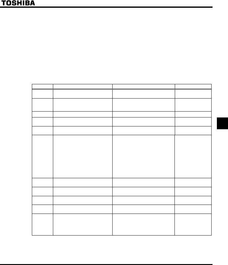
E6581381
F-79
6
+The following are available as common serial optional units:
•USB communication conversion unit (Model: USB001Z)
Communication cable (Model: CAB0011 (1m), CAB0013 (3m), CAB0015 (5m))
•Internal LonWorks® communication circuit board (Model: ILU007Z)
•Internal BACnet® communication circuit board (Model: BCN002Z)
•Internal Metasys® N2 communication circuit board (Model: MTS002Z)
•Internal Siemens APOGEETM FLN communication circuit board (Model: APG002Z)
These internal products require no interconnect cables, because of built-in type.
■Communication function parameters (Common serial options)
The data transfer speed, parity type, inverter number, and communication error trip time can be set/edited by
operation panel operation or communication function.
Title Function Adjustment range Default setting
H Communication rate 0: 9600bps
1: 19200bps 1
H Parity
0: NON (No parity)
1: EVEN (Even parity)
2: ODD (Odd parity)
1
H Inverter number 0-247 0
H Communication error trip time 0: Disabled (*)
1-100 (s) 0
H Communication waiting time 0.00: Regular communication
0.01-2.00 (s) 0.00
H
Setting of master and slave
for communication between
inverters
0: Slave (0 Hz command issued in
case the master inverter fails)
1: Slave (Operation continued in
case the master inverter fails)
2: Slave (Emergency stop tripping
in case the master inverter fails)
3: Master (transmission of
frequency commands)
4: Master (transmission of output
frequency signals)
0
H Communication command point 1
setting 0-100 (%) 0
H Communication command point 1
frequency 0-200.0 (Hz) 0.0
H Communication command point 2
setting 0-100 (%) 100
H Communication command point 2
frequency 0.0-200.0 (Hz) 50.0 (WP type)
60.0 (WN type)
H Selection of communication
protocol
0: Toshiba inverter protocol
1: ModbusRTU protocol
2: Metasys N2 protocol
3: APOGEE FLN protocol
4: BAC-net protocol
0

E6581381
F-80
6
Title Function Adjustment range Default setting
H Operation at communication error
by disconnection
0:Inverter stop, communication
command, frequency mode open
(by EOQF, HOQF)
1:None (continued operation)
2:Deceleration stop
3:Coast stop
4:Communication error (GTT
trip) or Network error (GTT trip)
4
H Number of motor poles for
communication
1: 2 poles
2: 4 poles
3: 6 poles
4: 8 poles
5: 10 poles
6: 12 poles
7: 14 poles
8: 16 poles
2
H Block write data 1 0
H Block write data 2
0: No selection
1: Command 1
2: Command 2
3: Frequency command
4: Output data on the terminal
board
5: Analog output for
communications
6: Motor speed command
0
H Block read data 1 0
H Block read data 2 0
H Block read data 3 0
H Block read data 4 0
H Block read data 5
0: No selection
1: Status information
2: Output frequency
3: Output current
4: Output voltage
5: Alarm information
6: PID feedback value
7: Input terminal board monitor
8: Output terminal board monitor
9: VIA terminal board monitor
10: VIB terminal board monitor
11: Output motor speed monitor
0
H Free notes 0-65535 0
* Disabled............ Indicates that the inverter will not be tripped even if a communication error occurs.
Trip .................. The inverter trips when a communication time-over occurs.
In this case a trip information GTT flashes on and off on the operation panel.
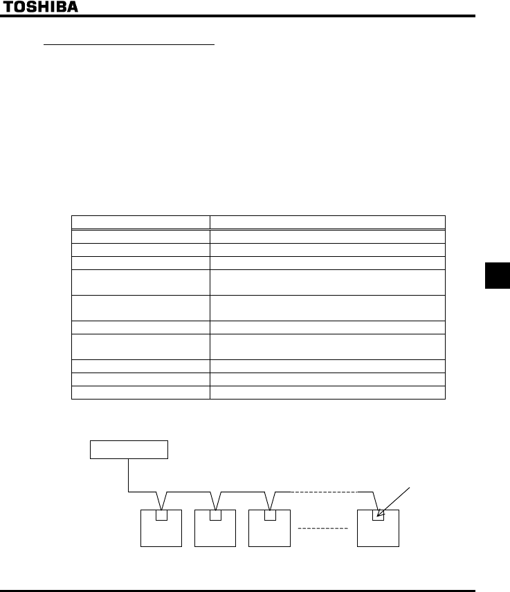
E6581381
F-81
6
6.21.2 Using the RS485
■Setting the communication functions
Setting commands and frequencies by communications has priority over sending commands from the
operation panel or the terminal board. Command/frequency setting by communications can therefore be
enabled, irrespective of the setting in the command mode (EOQF) or the frequency setting mode (HOQF).
When inverters are connected to each others, however, in order for slave inverters to recognize frequency
signals from the master inverter as frequency commands, the frequency setting mode selection 1 parameter
(HOQF) provided for each slave inverter needs to be set to 4 (serial communications). Refer to the
COMMUNICATIONS EQUIPMENT USER'S MANUAL for details.
However, when the input terminal function selection parameter is set to 48: SC/LC (Serial/Local selection),
the inverter can be operated with the settings of the command mode (EOQF) or the frequency setting mode
(HOQF) by external input.
■Transmission specifications
Item Specifications
Transmission scheme 2-wire, Half-duplex
Connection scheme Centralized control
Synchronization scheme Asynchronous
Transmission rate Default: 19200 baud (parameter setting)
Option: Either 9600 or 19200 baud
Character transmission ASCII code: JIS X 0201 8, 8-bit (fixed)
Binary code: Binary, 8-bit (fixed)
Stop bit length Inverter receiving: 1 bit, Inverter sending: 2 bits
Error detection Parity: Even, Odd, or None selectable by parameter setting;
check sum method
Character transmission format Receiving: 11-bit, Sending: 12-bit
Order of bit transmission Least significant bit first
Frame length Variable to a maximum of 17 bytes
■Example of connection for RS485-communication
<Example of connection>
Host computer
VF-FS1 VF-FS1 VF-FS1 VF-FS1
Option
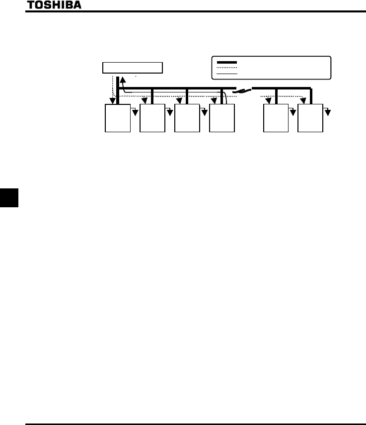
E6581381
F-82
6
<Independent communication>
Perform computer-inverter connection as follows to send operation frequency commands from the host
computer to inverter No. 3:
Host computer
FS1
No.29
FS1
No.30
: Wiring
:Data (host ? INV)
:Response data (INV R host)
FS1
No.02
FS1
No.01
FS1
No.00
** * *
Given away
Given away
Given away
Given away
Given away
FS1
No.03
"Given away": Only the inverter with the selected inverter number conducts data processing. All other
inverters, even if they have received the data, give it away and stand by to receive the
next data.
* : Use the terminal board to branch the cable.
(1) Data is sent from the host computer.
(2) Data from the computer is received at each inverter and the inverter numbers are checked.
(3) The command is decoded and processed only by the inverter with the selected inverter number.
(4) The selected inverter responds by sending the processing results, together with its own inverter
number, to the host computer.
(5) As a result, only the selected inverter starts operating in accordance with the operation frequency
command by communicating independently.
+For details of the communication function, refer to the separate instruction manual, “VF-FS1 Serial
Communication Function”.
Note : Limit the distance between the common serial optional units and the inverter to 5m.
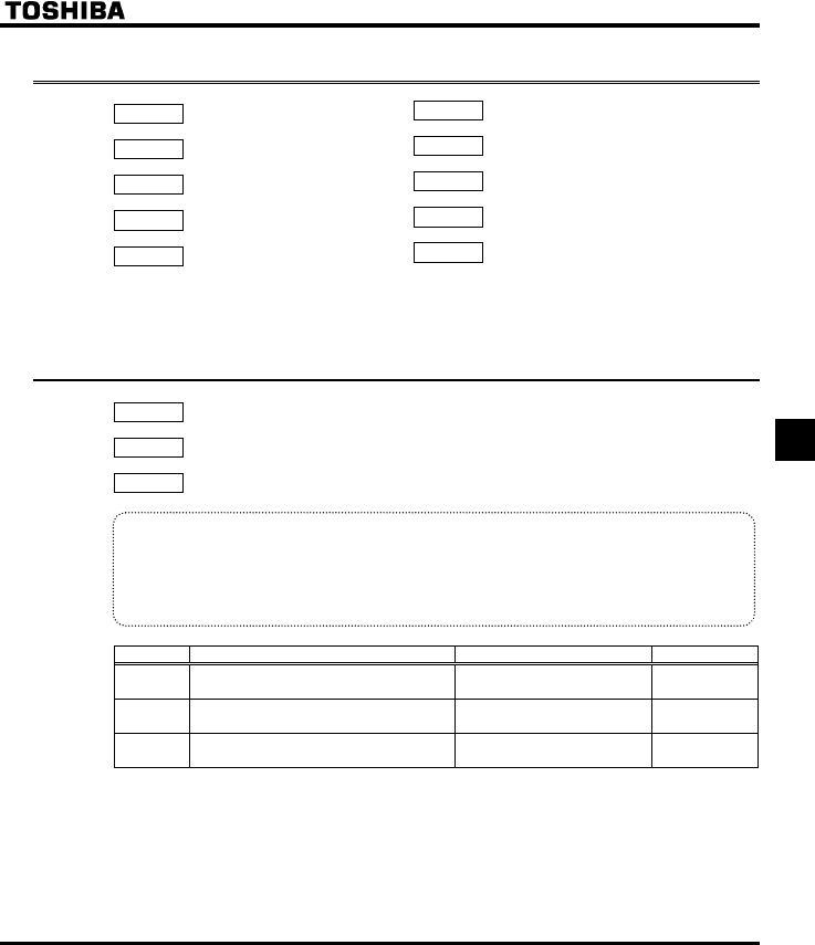
E6581381
F-83
6
6.22 Parameters for options
H : Parameter for option 1
H : Parameter for option 2
H : Parameter for option 3
H : Parameter for option 4
H : Parameter for option 5
These parameters can be used only when specific optional parts are installed. Do not use these parameters
unless such parts are installed.
6.23 Permanent magnetic motors
H : Step-out detection current level
H : Step-out detection time
H : High-speed torque adjustment coefficient
•Function
If the permanent magnet motor (PM motor) steps out and if the exciting current increases (it increases
in such a case) and remains above the value set with H for the period of time set with H,
the inverter will judge the motor to be stepping out and trip it. At that time, the trip message
"UQWV" is displayed.
Title Function Adjustment range Default setting
H Step-out detection current level 10 ~ 150 (%) / (A) 100
H Step-out detection time 0.0: No detection
0.1 ~ 25.0 [s] 0.0
H High-speed torque adjustment coefficient 0.00 ~ 650.0 0.00
Note 1: When using an PM motor, consult your Toshiba dealer, since the inverter is not compatible with all
types of PM motors.
Note 2: The inverter may fail to detect step-out in some cases, because it uses an electrical method to detect
step-out. To avoid detection failures, you are recommended to install a mechanical step-out detector.
Note 3: There is no need adjust H under normal conditions. (Do not change the setting, unless
otherwise instructed by Toshiba technical staff.)
H : Parameter for option 6
H : Parameter for option 7
H : Parameter for option 8
H : Parameter for option 9
H : Parameter for option 10
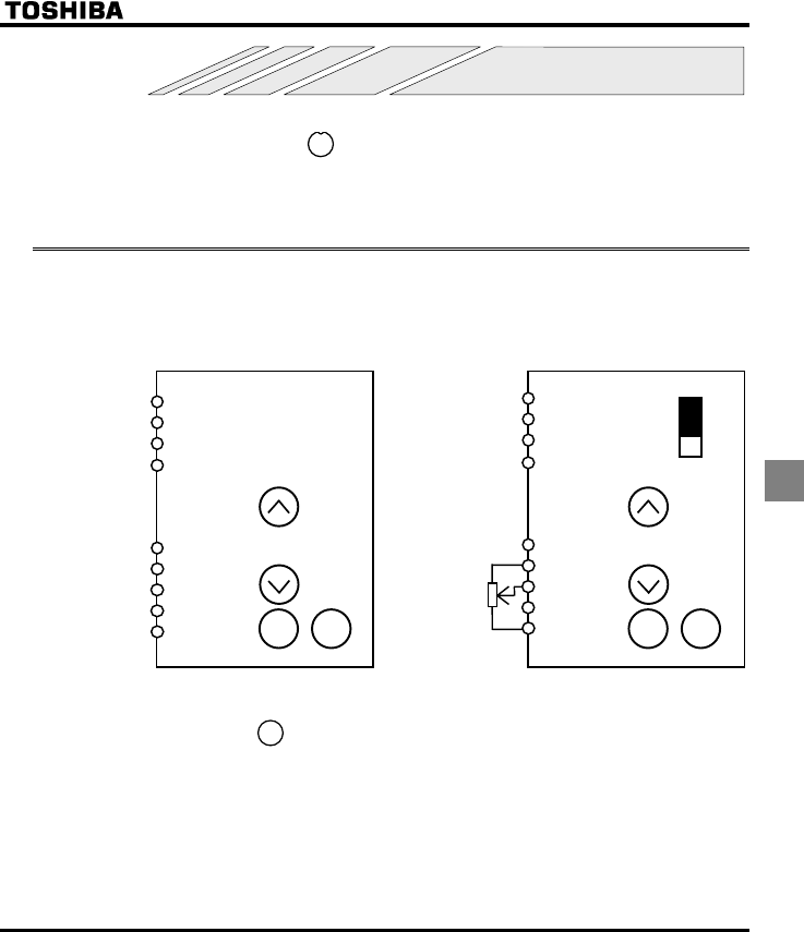
E6581381
G-1
7
7. Applied operation
Applied operation can be performed by selecting the frequency mode and command mode setting. However in
case the LOCAL mode is selected by key (lighting a LOC/REM lamp), frequency setting mode and
command mode are fixed operation panel key setting mode. The following explanations are applied REMOTE
mode only.
7.1 Setting the operation frequency
Applied operation can be performed by selecting the inverter frequency setting. To make settings for applied
operation, use the basic parameter HOQF (selection of frequency setting mode 1), and the extended
parameters H (frequency priority selection) and H (selection of frequency setting mode 2).
(1) Operation panel key setting (2) External potentiometer setting
F
R
RES
CC
PLC
PP
VIA
VIB
CC
F
R
RES
CC
PLC
PP
VIA
VIB
CC
VIA
V
SW3
STOPRUNSTOPRUN
HOQF:
H:
Enter the number with the operation panel
keys, then press the key to conform.
(Save the setting)
HOQF:
H:
Use the parameters H to H for this
setting.
LOC
REM
ENT
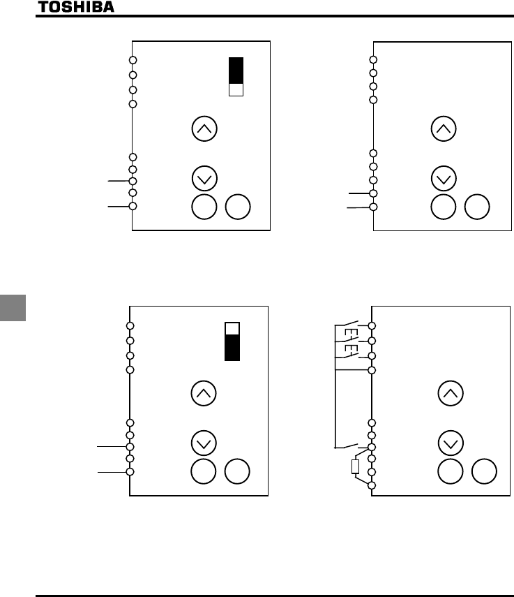
E6581381
G-2
7
(3) Input voltage setting 1 (0 to 10 Vdc) (4) Input voltage setting 2 (0 to 10 Vdc)
Voltage signal
F
R
RES
CC
PLC
PP
VIA
VIB
CC
Voltage signal
F
R
RES
CC
PLC
PP
VIA
VIB
CC
VIA
V
SW3
STOPRUNSTOPRUN
HOQF:
H:
Use the parameters Hto H for this
setting.
HOQF:
H:
Use the parameters Hto H for this
setting.
(5) Input current setting (4 to 20 mAdc) (6) External contact UP/DOWN
F
R
RES
CC
PLC
PP
VIA
VIB
CC
Current
signal
F
R
(
UP
)
RES
(
DOWN
)
PLC
PP
VIA
(
CLR
)
VIB
CC
VIA
I
SW3 CC
P24
STOPRUNSTOPRUN
HOQF:
H:
Use parameters H to H for this
setting.
(H: 20%)
HOQF: , H:
Use the parameters H to H for this setting.
To change the frequency when power is off, set
H: (Rewriting of H when power is turned
off.)
H: (Allocation of UP)
H: (Allocation of DOWN)
H: (Allocation of CLR)
H: (VIA-contact input (Sink))
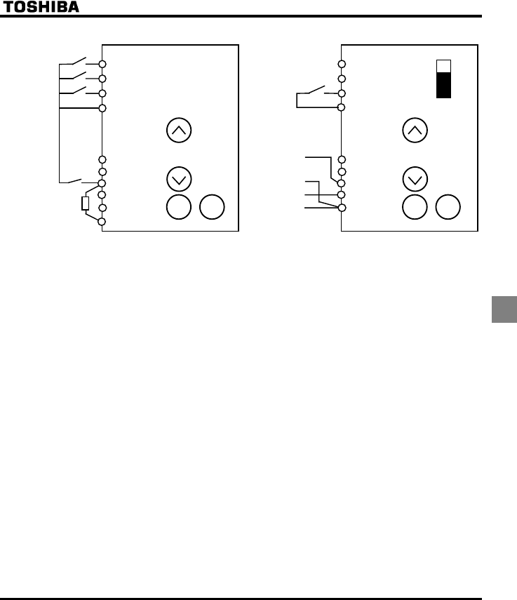
E6581381
G-3
7
(7) Preset-speed (8) Voltage/current switching 1
F
R
(
SS1
)
RES
(
SS2
)
PLC
PP
VIA
(
SS3
)
VIB
CC
F
R
RES (FCHG)
CC
PLC
PP
CC
VIA
VIB
VIA
I
Voltage signal
Current signal
SW3
CC
P24
STOPRUNSTOPRUN
EOQF: (Terminal board)
UT to UT: 1-7-speed run
To select 7-speed run, use the terminals R, RES
and VIA.
H: (Allocation of SS1)
H: (Allocation of SS2)
H: (Allocation of SS3)
H: (VIA-contact input (Sink))
H: (Forced switching of FCHG)
H: (Allocation of FCHG)
HOQF:
H:
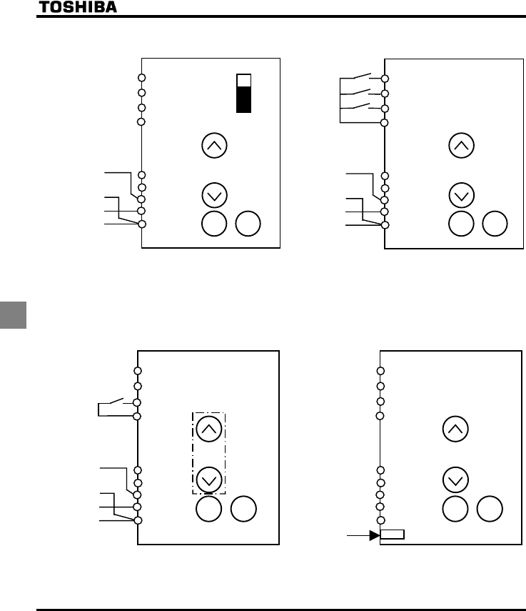
E6581381
G-4
7
(9) Voltage/current switching 2 (10) Switching between analog setting and preset
speed setting
F
R
RES
CC
PLC
PP
CC
VIA
VIB
VIA
I
Voltage signal
Current signal
SW3
F
R (SS1)
RES (SS2)
CC
PLC
PP
VIA
VIB
CC
Voltage
signal
Voltage/current
signal
STOPRUNSTOPRUN
H: (Automatic switching)
HOQF:
H:
HOQF: (VIA) or (VIB)
EOQF: (Terminal board)
H:
To switch to preset-speed setting, use the
external terminals R and RES
H: (Allocation of SS1)
H: (Allocation of SS2)
(11) Switching between analog setting and terminal
setting from the operation panel
(12) Setting by means of a remote input device
F
R
PLC
PP
VIA
CC
RES (FCHG)
CC
VIB
Voltage
signal
Voltage/current
signal
F
R
RES
CC
PLC
PP
VIA
VIB
CC
Connector for communication
STOPRUNSTOPRUN
HOQF: (Operation panel)
H: (Allocation of FCHG)
To switch to H setting, enter the
command through FCHG.
H: H: (VIA) or (VIB).
HOQF: (Serial communication)
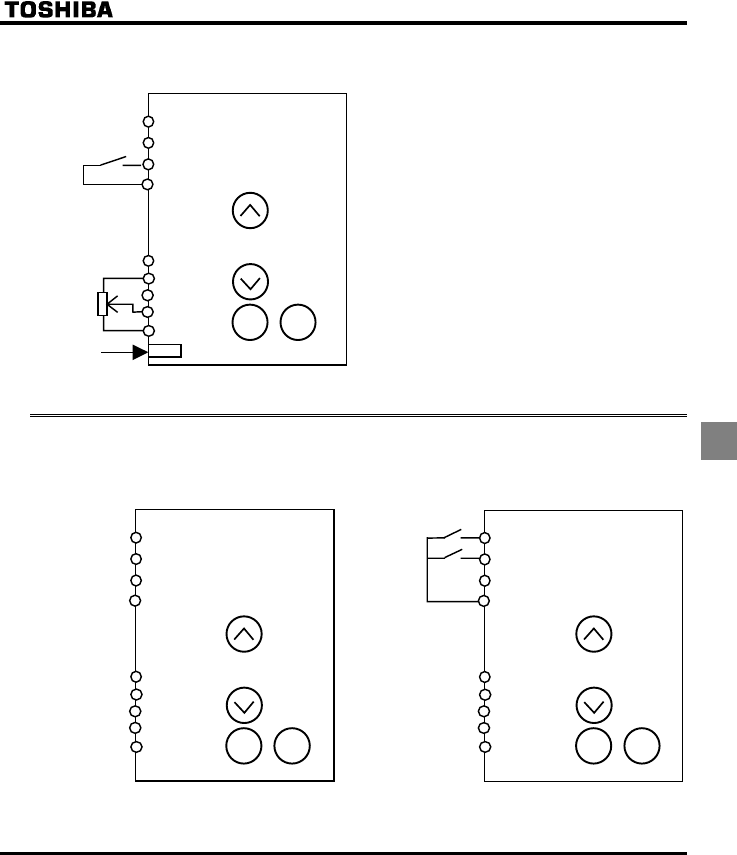
E6581381
G-5
7
(13)Switching between communication and terminal
control
F
R
RES
(
SC/LC
)
CC
PLC
PP
VIA
VIB
CC
Connector for commucation
STOPRUN
Communication command fa00h 14bit: 1
HOQF: or
H: (Allocation of SL/LC)
Switched to terminal when a command is
entered through SC and LC during operation by
means of communication
7.2 Setting the operation mode
Applied operation can be performed by selecting the operation mode. To set the operation mode, use the basic
parameter EOQF (command mode selection) and the input terminal selection parameter.
(1) Operation panel operation (2) Terminal board operation
F
R
RES
CC
PLC
PP
VIA
VIB
CC
F
R
RES
CC
PLC
PP
VIA
VIB
CC STOPRUNSTOPRUN
EOQF: (Operation panel) EOQF: (Terminal board)
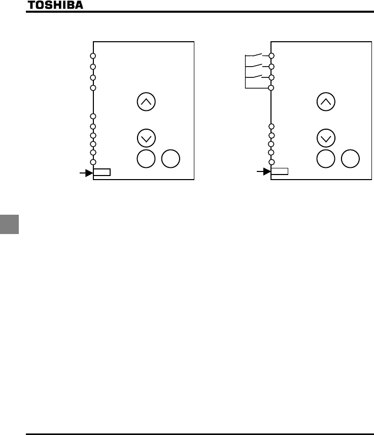
E6581381
G-6
7
(3) Operation from an external input device (4) Switching from communication to the terminal
board
F
R
RES
CC
CC
PLC
PP
VIA
VIB
CC
F
R
RES (SC/LC)
CC
PLC
PP
VIA
VIB
CC
Connector for communication Connector for communication
STOPRUNSTOPRUN
EOQF: (Serial communication) EOQF: (Terminal board)
H: (Allocation of SC/LC)
Remote control can be switched forcefully
to terminal control from the external SC/LC by
setting the remote command fa00h 15-bit at 1.
Operation is controlled from the terminal board.
E6581381
H-1
8
8. Monitoring the operation status
Refer to section 4.1 about flow of monitor.
8.1 Status monitor mode
8.1.1 Status monitor under normal conditions
In this mode, you can monitor the operation status of the inverter.
To display the operation status during normal operation:
Press the key twice.
Setting procedure (eg. operation at 60Hz)
Item displayed Key
operated
LED
display
Communic
ation No. Description
The operation frequency is displayed (Operation at
60Hz). (When standard monitor display selection
H is set at 0 [operation frequency])
Parameter setting
mode CWH The first basic parameter “CWH” (Wizard function)
is displayed.
Direction of
rotation HTH FE01 The direction of rotation is displayed.
(HTH: forward run, HTT: reverse run)
Operation
frequency
command
H FE02
The operation frequency command value (Hz/free
unit) is displayed.
Load current E FE03 The inverter output current (load current) (%/A) is
displayed.
Input voltage [ FE04 The inverter input (DC) voltage (%/V) is displayed.
Output voltage R FE05 The inverter output voltage (%/V) is displayed.
Torqu e SQ FE18 The torque (%) is displayed.
Torque current Y FE20 The torque current (%/A) is displayed.
Inverter load factor N FE27 The inverter load factor (%) is displayed.
Input power M FE29 The inverter input power (kW) is displayed.
Output power J FE30 The inverter output power (kW) is displayed.
Operation
frequency Z FD00 The operation frequency (Hz/free unit) is
displayed.
(Continued overleaf)
Note 1
Note 2
Note 3
MODE
MODE
MODE
E6581381
H-2
8
(Continued)
Item displayed Key
operated
LED
display
Communic
ation No. Description
Input terminal __KK FE06
The ON/OFF status of each of the control signal
input terminals (F, R, RES and VIA) is displayed in
bits.
ON:
OFF: _
Output terminal _K FE07
The ON/OFF status of each of the control signal
output terminals (RY and FL) is displayed in bits.
ON:
OFF: _
CPU1 version X FE08 The version of the CPU1 is displayed.
CPU2 version XY FE73 The version of the CPU2 is displayed.
Memory version XG FE09 The version of the memory mounted is displayed.
PID feedback F FE22 The PID feedback value is displayed. (Hz/free unit)
Frequency
command value
(PID-computed)
D FE15 The PID-computed frequency command value is
displayed. (Hz/free unit)
Integral input
power M FE76 The integrated amount of power (kWh) supplied to
the inverter is displayed.
Integral output
power J FE77 The integrated amount of power (kWh) supplied
from the inverter is displayed.
Rated current C FE70 The rated current of the inverter (A) is displayed.
Output speed FE90 Displays the motor speed ( min-1) by calculating
with output frequency and pole numbers.
Communication
counter O FA15 Displays the counter numbers of communication
through the network.
Normal state
communication
counter
P FA16
Displays the counter numbers of communication
only at normal state in the all communication
through network.
(Continued overleaf)
_K
RY-RC
FL
Note 5
Note 5
Note 4
__KK
VIA F
R
RES
E6581381
H-3
8
(Continued)
Item displayed Key
operated
LED
display
Communic
ation No. Description
Past trip 1 QE ⇔FE10 Past trip 1 (displayed alternately)
Past trip 2 QJ ⇔FE11 Past trip 2 (displayed alternately)
Past trip 3 QR ⇔FE12 Past trip 3 (displayed alternately)
Past trip 4 PGTT ⇔FE13 Past trip 4 (displayed alternately)
Parts replacement
alarm information O___K FE79
The ON/OFF status of each of the cooling fan,
circuit board capacitor, main circuit capacitor of
parts replacement alarm or cumulative operation
time are displayed in bits.
ON:
OFF: _
Cumulative
operation time V FE14 The cumulative operation time is displayed.
(0.01=1 hour, 1.00=100 hours)
Default display
mode The operation frequency is displayed (Operation at
60Hz).
Note 6
Note 7
Note 8
Note 6
Note 6
Note 6
o
p
eration
O
___K
C
oolin
g
fan
C
umulative
time Control circuit board ca
p
acitor
Main circuit ca
p
acitor
MODE
E6581381
H-4
8
8.1.2 Display of detailed information on a past trip
Details on a past trip (of trips 1 to 4) can be displayed, as shown in the table below, by pressing the key
when the trip record is selected in the status monitor mode.
Unlike the "Display of detailed trip information at the occurrence of a trip" in 8.2.2, details on a past trip can be
displayed, even after the inverter is turned off or reset.
Item displayed Key
operated LED display Description
Past trip 1 QE
⇔Past trip 1 (displayed alternately)
Continuous trips P The number of time the same trip occurred in succession is
displayed. (Unit: times)
Operation
frequency Z The operation frequency when the trip occurred is
displayed.
Direction of
rotation HTH The direction of rotation when the trip occurred is displayed.
(HTH: Forward run, HTT: Reverse run)
Operation
frequency
command
H
The operation command value when the trip occurred is
displayed.
Load current E The inverter output current when the trip occurred is
displayed. (%/A)
Input voltage [ The inverter input voltage (DC) when the trip occurred is
displayed. (%/V).
Output voltage R The inverter output voltage when the trip occurred is
displayed. (%/V)
Input terminal __KK
The ON/OFF statuses of the control input terminals (F, R,
RES and VIA) are displayed in bits.
ON:
OFF: _
Output terminal _K
The ON/OFF statuses of the control output terminals (RY
and FL) are displayed in bits.
ON:
OFF: _
Cumulative
operation time V
The cumulative operation time when the trip occurred is
displayed.
(0.01=1 hour, 1.00=100 hours)
Past trip 1 QE
⇔ Press this key to return to past trip 1.
_K
RY-RC
FL
__KK
VIA
RES
R
F
Note 1
Note 3
Note 4
Note 5
Note 8
Note 2
Note 10
ENT
ENT
MODE

E6581381
H-5
8
8.2 Display of trip information
8.2.1 Trip code display
If the inverter trips, an error code is displayed to suggest the cause. Since trip records are retained, information
on each trip can be displayed anytime in the status monitor mode.
■Display of trip information
Error code Failure
code Description
PGTT(*) 0000 No error
QE 0001 Overcurrent during acceleration
QE 0002 Overcurrent during deceleration
QE 0003 Overcurrent during constant speed operation
QEN 0004 Load-side overcurrent during start-up
QEC 0005 Armature-side overcurrent during start-up
GRJ 0008 Input phase failure or exhaustion of main circuit capacitor
GRJ 0009 Output phase failure
QR 000A Overvoltage during acceleration
QR 000B Overvoltage during deceleration
QR 000C Overvoltage during constant-speed operation
QN 000D Inverter overload trip
QN 000E Motor overload trip
QJ 0010 Overheating trip or thermal detector failure
G0011 Emergency stop
GGR 0012 E2PROM fault 1 (writing error)
GGR 0013 E2PROM fault 2 (initialization error) or power-off during the setting of
V[R
GGR 0014 E2PROM fault 3 (reading error)
GTT 0015 Inverter RAM fault
GTT 0016 Inverter ROM fault
GTT 0017 CPU fault trip 1
GTT 0018 Communication error
GTT 001A Current defector fault
GTT 001B Network error
WE 001D Small-current trip
WR 001E Undervoltage trip
QV 0020 Over-torque trip
GH 0022 Ground fault
QER 0025 Overcurrent flowing in element during acceleration
(Continued overleaf)
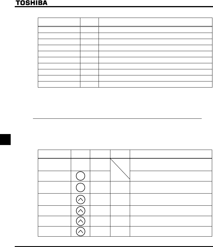
E6581381
H-6
8
(Continued)
Error code Failure
code Description
QER 0026 Overcurrent flowing in element during deceleration
QER 0027 Overcurrent flowing in element during constant-speed operation
GVP 0054 Auto-tuning error
GV[R 0029 Inverter type error
QJ 002E External thermal input
G 0032 VIA cable break
G 0033 Communication error between CPUs
G 0034 V/F control error
G 0035 CPU fault 2
UQWV 002F Step-out (for PM motors only)
Note: Past trip records (trip records retained or trips that occurred in the past) can be called up.
⇒ See section 8.1 "Status monitor mode" for the call-up procedure.
(*) Strictly speaking, this code is not an error code; this code is displayed to show the absence of error
when the past trip monitor mode is selected.
8.2.2 Display of trip information at the occurrence of a trip
At the occurrence of a trip, the same information as that displayed in the mode described in 8.1.1, "Status monitor
under normal conditions," can be displayed, as shown in the table below, if the inverter is not turned off or reset.
To display trip information after turning off or resetting the inverter, follow the steps described in 8.1.2, "Display of
detailed information on a past trip."
■Example of call-up of trip information
Item displayed Key
operated
LED
display
Communic
ation No. Description
Cause of trip QR
Status monitor mode (The code blinks if a trip
occurs.)
The motor coasts and comes to a stop (coast stop).
Parameter setting
mode CWH The first basic parameter “CWH” (Wizard function)
is displayed.
Direction of
rotation HTH FE01
The direction of rotation at the occurence of a trip
is displayed. (HTH: forward run, HTT:
reverser run).
Operation
frequency
command
H FE02
The operation frequency command value (Hz/free
unit) at the occurrence of a trip is displayed.
Load current E FE03 The output power of the inverter at the occurrence
of a trip (%/A) is displayed.
Input voltage [ FE04 The inverter input (DC) voltage (%/V) at the
occurrence of a trip is displayed.
Output voltage R FE05 The output voltage of the inverter at the
occurrence of a trip (%/V) is displayed.
(Continued overleaf)
Note 3
Note 2
Note 1
MODE
MODE
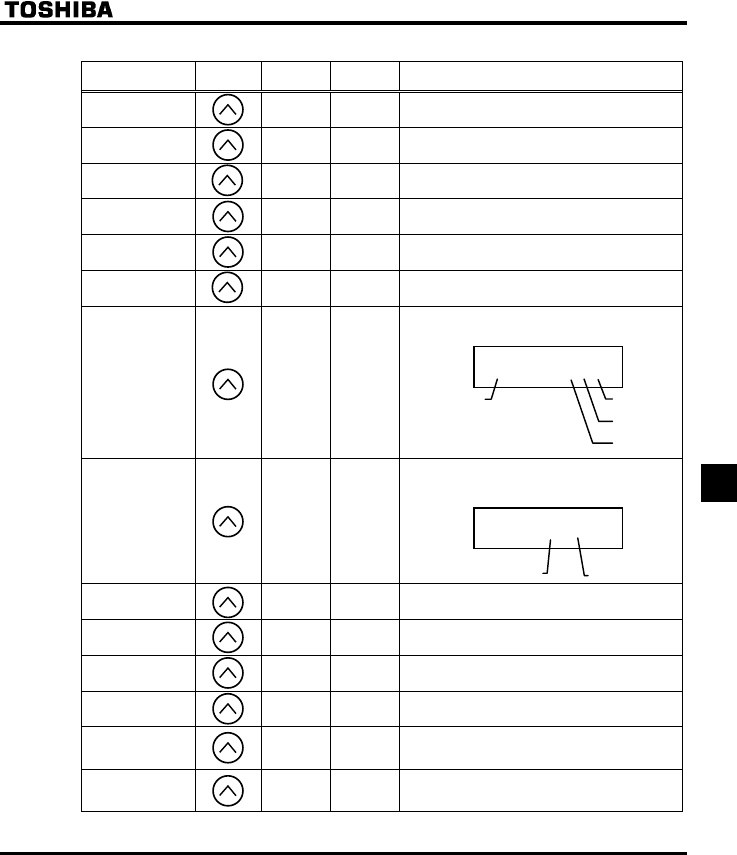
E6581381
H-7
8
(Continued)
Item displayed Key
operated
LED
display
Communic
ation No. Description
Torqu e SQ FE18 The torque at the occurrence of a trip (%) is
displayed.
Torque current Y FE20 The torque current (%/A) at the occurrence of a
trip is displayed.
Inverter load factor N FE27 The inverter load factor (%) at the occurrence of a
trip is displayed.
Input power M FE29 The inverter input power (kW) at the occurrence of
a trip is displayed.
Output power J FE30 The inverter output power (kW) at the occurrence
of a trip is displayed.
Operation
frequency Z FE00 The inverter output frequency (Hz/free unit) at the
occurrence of a trip is displayed.
Input terminal __KK FE06
The ON/OFF statuses of the control input
terminals (F, R, RES and VIA) are displayed in
bits.
ON:
OFF: _
Output terminal _K FE07
The ON/OFF status of each of the control signal
output terminals (RY and FL) at the occurrence of
a trip is displayed in bits.
ON:
OFF: _
CPU1 version X FE08 The version of the CPU1 is displayed.
CPU2 version XY FE73 The version of the CPU2 is displayed.
Memory version XG FE09 The version of the memory mounted is displayed.
PID feedback F FE22 The PID feedback value at the occurrence of a trip
is displayed. (Hz/free unit)
Frequency
command value
(PID-computed)
D FE15
The PID-computed frequency command value at
the occurrence of a trip is displayed. (Hz/free unit)
Integral input
power M FE76
The integrated amount of power (kWh) supplied to
the inverter is displayed.
(0.01=1kWh, 1.00=100kWh)
(Continued overleaf)
_K
RY-RC
FL
__KK
VIA
RES
R
F
Note 4
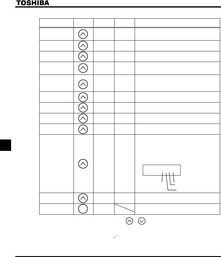
E6581381
H-8
8
(Continued)
Item displayed Key
operated
LED
display
Communic
ation No. Description
Integral output
power J FE77
The integrated amount of power (kWh) supplied
from the inverter is displayed.
(0.01=1kWh, 1.00=100kWh)
Rated current C FE70 The inverter rated current (A) at the occurrence of
a trip is displayed.
Output speed FE90 Displays the motor speed ( min-1) by calculating
with output frequency and pole numbers.
Communication
counter O FA15
Displays the counter numbers of communication
through the network.
Note that they are current values, not at tripping.
Normal state
communication
counter
P FA16
Displays the counter numbers of communication
only at normal state in the all communication
through network.
Note that they are current values, not at tripping.
Past trip 1 QR ⇔FE10 Past trip 1 (displayed alternately)
Past trip 2 QJ ⇔FE11 Past trip 2 (displayed alternately)
Past trip 3 QR ⇔FE12 Past trip 3 (displayed alternately)
Past trip 4 PGTT ⇔FE13 Past trip 4 (displayed alternately)
Parts replacement
alarm information O___K FE79
The ON/OFF status of each of the cooling fan,
circuit board capacitor, main circuit capacitor of
parts replacement alarm or cumulative operation
time are displayed in bits.
ON:
OFF: _
Cumulative
operation time V FE14 The cumulative operation time is displayed.
(0.01=1 hour, 1.00=100 hours)
Default display
mode QR The cause of the trip is displayed.
Note 1: Items displayed can be changed by pressing or key in the each monitor mode.
Note 2: You can switch between % and A (ampere)/V (volt), using the parameter H (current/voltage unit
selection).
Note 3: The input (DC) voltage displayed is 1 2 times as large as the rectified d.c. input voltage.
Note 7
Note 8
Note 6
Note 6
Note 6
Note 6
O
___K
C
oolin
g
fan
o
p
eration time Control circuit board ca
p
acitor
Main circuit ca
p
acitor
MODE

E6581381
H-9
8
Note 4: The number of bars displayed varies depending on the setting of H (analog input/logic input
function selection). The bar representing VIA is displayed only when the logic input function is assigned
to the VIA terminal, respectively.
If H = : The bar representing VIA is not displayed.
If H = or : The bar representing VIA is displayed.
Note 5: The integrated amounts of input and output power will be reset to zero, if you press and hold down the
key for 3 seconds or more when power is off or when the input terminal function CKWH (input
terminal function: 51) is turned on or displayed.
Note 6: Past trip records are displayed in the following sequence: 1 (latest trip record) ⇔2⇔3⇔4 (oldest trip
record). If no trip occurred in the past, the message “PGTT” will be displayed. Details on past trip
record 1, 2, 3 or 4 can be displayed by pressing the key when past trip 1, 2, 3 or 4 is displayed.
⇒ For more information, see section 8.1.2.
Note 7: Parts replacement alarm is displayed based on the value calculated from the annual average ambient
temperature, the ON time of the inverter, the operating time of the motor and the output current ( load
factor) specified using H. Use this alarm as a guide only, since it is based on a rough estimation.
Note 8: The cumulative operation time increments only when the machine is in operation.
Note 9: At the occurrence of a trip, maximum values are not always recorded and displayed for reasons of
detecting time.
Note10: If there is no trip record, PGTT is displayed.
,Of the items displayed on the monitor, the reference values of items expressed in percent are listed below.
•Load current: The current monitored is displayed. The reference value (100% value) is
the rated output current indicated on the nameplate. The unit can be
switched to A (amperes).
•Input voltage: The voltage displayed is the voltage determined by converting the voltage
measured in the DC section into an AC voltage. The reference value
(100% value) is 200 volts for 200V models, 400 volts for 400V models.
The unit can be switched to V (volts).
•Torque: The torque generated by the drive motor is displayed. The reference value
(100% value) is the rated torque of the motor.
•Torque current: The current required to generate torque is calculated from the load current
by vector operations. The value thus calculated is displayed. The
reference value (100% value) is the value at the time when the load
current is 100%.
•Load factor of inverter: Depending on the PWM carrier frequency (H) setting and so on, the
actual rated current may become smaller than the rated output current
indicated on the nameplate. With the actual rated current at that time (after
a reduction) as 100%, the proportion of the load current to the rated
current is indicated in percent. The load factor is also used to calculate the
conditions for overload trip (QN).
ENT
ENT

E6581381
I-1
9
9. Measures to satisfy the standards
9.1 How to cope with the CE directive
In Europe, the EMC directive and the low-voltage directive, which took effect in 1996 and 1997, respectively,
make it obligatory to put the CE mark on every applicable product to prove that it complies with the directives.
Inverters do not work alone but are designed to be installed in a control panel and always used in combination
with other machines or systems which control them, so they themselves are not considered to be subject to the
EMC directive. However, the CE mark must be put on all inverters because they are subject to the low-voltage
directive.
The CE mark must be put on all machines and systems with built-in inverters because such machines and
systems are subject to the above directives. It is the responsibility of the manufacturers of such final products to
put the CE mark on each one. If they are "final" products, they might also be subject to machine-related directives.
It is the responsibility of the manufacturers of such final products to put the CE mark on each one. In order to
make machines and systems with built-in inverters compliant with the EMC directive and the low-voltage directive,
this section explains how to install inverters and what measures should be taken to satisfy the EMC directive.
We have tested representative models with them installed as described later in this manual to check for
conformity with the EMC directive. However, we cannot check all inverters for conformity because whether or not
they conform to the EMC direction depends on how they are installed and connected. In other words, the
application of the EMC directive varies depending on the composition of the control panel with a built-in
inverter(s), the relationship with other built-in electrical components, the wiring condition, the layout condition, and
so on. Therefore, please verify yourself whether your machine or system conforms to the EMC directive.
9.1.1 About the EMC directive
Inverters themselves are not subject to approval for CE marking.
The CE mark must be put on every final product that includes an inverter(s) and a motor(s). The VF-FS1 series of
inverters complies with the EMC directive if an EMI filter recommended by Toshiba is connected to it and wiring is
carried out correctly.
■EMC directive 89/336/EEC
The EMC standards are broadly divided into two categories; immunity- and emission-related standards, each of
which is further categorized according to the operating environment of each individual machine. Since inverters
are intended for use with industrial systems under industrial environments, they fall within the EMC categories
listed in Table 1 below. The tests required for machines and systems as final products are almost the same as
those required for inverters.
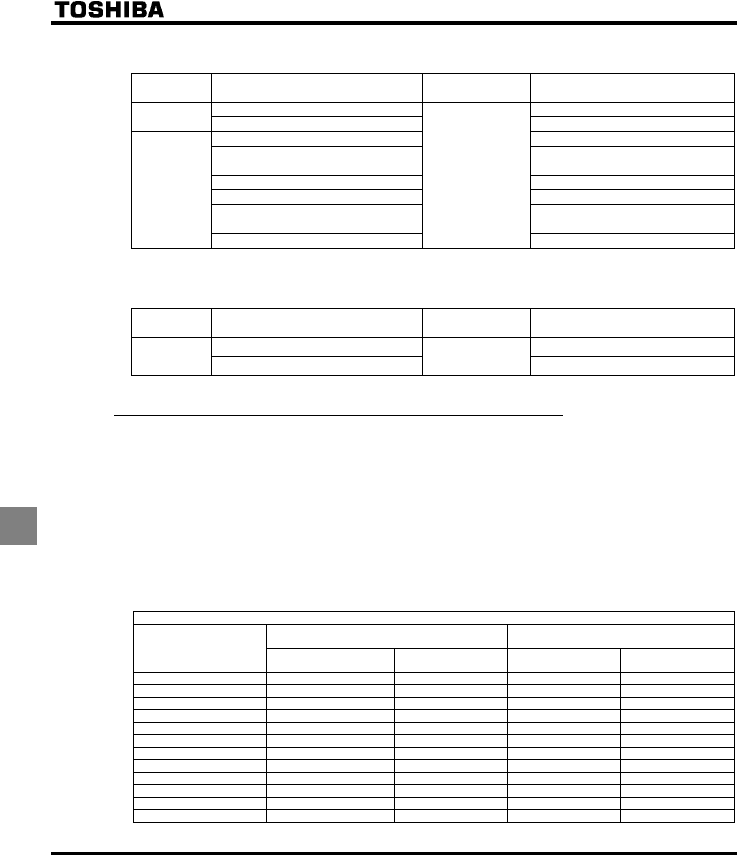
E6581381
I-2
9
Table 1 EMC standards
Category Subcategory Product
standards Test standard and level
Radiation noise IEC61800-3
Emission Transmission noise IEC61800-3
Static discharge IEC61000-4-2
Radioactive radio-frequency
magnetic contactor field
IEC61000-4-3
First transient burst IEC61000-4-4
Lightning surge IEC61000-4-5
Radio-frequency
induction/transmission interference
IEC61000-4-6
Immunity
Voltage dip/Interruption of power
IEC 61800-3
IEC61000-4-11
Emission standards other than the above are applied to inverters when used in a commercial environment but not
an industrial environment.
Category Subcategory Product
standards Test standard and level
Radiation noise IEC61800-3
Emission Transmission noise IEC 61800-3 IEC61800-3
9.1.2 Measures to satisfy the EMC directive
This subsection explains what measures must be taken to satisfy the EMC directive.
(1) Insert a recommended EMI filter (Table 2) on the input side of the inverter to reduce and transmission noise
and radiation noise from input cables.
In the combinations listed in Table 2, Inverters are tested in these combination to see if they comply with
transmission noise standards. For inverters used in Japan, it is recommended to use the NF series of noise
filters.
Table 2 lists noise filters recommended for the inverters.
Table 2 Combinations of inverter and EMI filter
Three-phase 200V class
Combination of inverter and filter
Transmission noise
EN61800-3, 1st Environment, C2
Transmission noise
EN61800-3, 1st Environment, C1
Inverter
Applicable filters Length of motor
connecting cable (m) Applicable filters Length of motor
connecting cable (m)
VFFS1-2004PM EMFS11-4015BZ 50 EMFS11-4015BZ 1
VFFS1-2007PM EMFS11-4015BZ 50 EMFS11-4015BZ 1
VFFS1-2015PM EMFS11-4015BZ 50 EMFS11-4015BZ 1
VFFS1-2022PM EMFS11-4015BZ 50 EMFS11-4015BZ 1
VFFS1-2037PM EMFS11-4025CZ 50 EMFS11-4025CZ 1
VFFS1-2055PM EMFS11-4047DZ 50 EMFS11-4047DZ 1
VFFS1-2075PM EMFS11-4047DZ 50 EMFS11-4047DZ 1
VFFS1-2110PM EMFS11-2083EZ 50 EMFS11-2083EZ 1
VFFS1-2150PM EMFS11-2083EZ 50 EMFS11-2083EZ 1
VFFS1-2185PM EMFS11-2083EZ 50 EMFS11-2083EZ 1
VFFS1-2220PM EMF3-4090F 100 EMF3-4090F 50
VFFS1-2300PM EMF3-4180H 100 EMF3-4180H 50
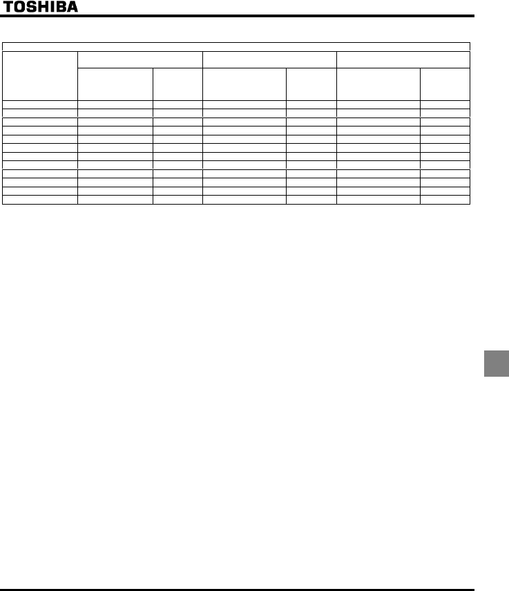
E6581381
I-3
9
Three-phase 400V class
Combination of inverter and filter
Transmission noise
EN61800-3, 1st Environment, C2
Transmission noise
EN61800-3, 1st Environment, C1
Transmission noise
EN61800-3, 2nd Environment, C3
Inverter
Applicable filters
Length of
motor
connecting
cable (m)
Applicable filters
Length of
motor
connecting
cable (m)
Applicable filters
Length of
motor
connecting
cable (m)
VFFS1-4004PL With a built-in filter 5 EMFS11-4015BZ 20 EMFS11-4015BZ 50
VFFS1-4007PL With a built-in filter 5 EMFS11-4015BZ 20 EMFS11-4015BZ 50
VFFS1-4015PL With a built-in filter 5 EMFS11-4015BZ 20 EMFS11-4015BZ 50
VFFS1-4022PL With a built-in filter 5 EMFS11-4015BZ 20 EMFS11-4015BZ 50
VFFS1-4037PL With a built-in filter 5 EMFS11-4025CZ 20 EMFS11-4025CZ 50
VFFS1-4055PL With a built-in filter 5 EMFS11-4025CZ 20 EMFS11-4025CZ 50
VFFS1-4075PL With a built-in filter 5 EMFS11-4047DZ 20 EMFS11-4047DZ 50
VFFS1-4110PL With a built-in filter 5 EMFS11-4047DZ 20 EMFS11-4047DZ 50
VFFS1-4150PL With a built-in filter 5 EMFS11-4049EZ 20 EMFS11-4049EZ 50
VFFS1-4185PL With a built-in filter 5 EMFS11-4049EZ 20 EMFS11-4049EZ 50
VFFS1-4220PL With a built-in filter 50 EMF3-4090F 100 EMF3-4090F 100
VFFS1-4300PL With a built-in filter 50 EMF3-4092G 100 EMF3-4092G 100
(2) Use shielded power cables, such as inverter output cables, and shielded control cables. Route the cables
and wires so as to minimize their lengths. Keep a distance between the power cable and the control cable
and between the input and output wires of the power cable. Do not route them in parallel or bind them
together, instead cross at right angle.
(3) Install the inverter and the filter on the same metal plate. It is more effective in limiting the radiation noise to
install the inverter in a sealed steel cabinet. Using wires as thick and short as possible, earth the metal plate
and the control panel securely with a distance kept between the earth cable and the power cable.
(4) Route the EMI filter input and output wires apart from each other.
(5) To suppress radiation noise from cables, ground all shielded cables through a noise cut plate.
It is effective to earth shielded cables in the vicinity of the inverter, cabinet and filter (within a radius of 10cm
from each of them). Inserting a ferrite core in a shielded cable is even more effective in limiting the radiation
noise.
(6) To further limit the radiation noise, insert a zero-phase reactor in the inverter output line and insert ferrite
cores in the earth cables of the metal plate and cabinet.
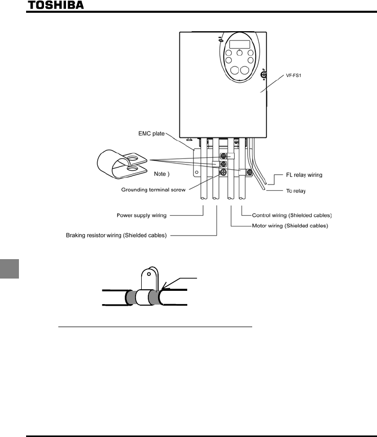
E6581381
I-4
9
[Example of wiring]
Note: Strip and earth the shielded cable, following the example shown in Fig.
Strip the cable and fix it to the metal plate by means
of a metal saddle for electrical work or equivalent.
Shielded cable
9.1.3 About the low-voltage directive
The low-voltage directive provides for the safety of machines and systems. All Toshiba inverters are CE-marked
in accordance with the standard EN 50178 specified by the low-voltage directive, and can therefore be installed in
machines or systems and imported without problem to European countries.
Applicable standard: EN/IEC 61800-5-1
Electronic equipment for use in power installations
Electronic equipment for use in power installations
Pollution level: 2 (5.2.15.2)
Overvoltage category: 3
200V class - 3.0mm (5.2.16.1)
400V class - 5.5mm (5.2.16.1)

E6581381
I-5
9
EN 50178 applies to electrical equipment intended specially for use in power installations, and sets out the
conditions to be observed for electric shock prevention when designing, testing, manufacturing and installing
electronic equipment for use in power installations.
9.1.4 Measures to satisfy the low-voltage directive
When incorporating the inverter into a machine or system, it is necessary to take the following measures so that
the inverter satisfies the low-voltage directive.
(1) Install the inverter in a cabinet and ground the inverter enclosure. When doing maintenance, be extremely
careful not to put your fingers into the inverter through a wiring hole and touch a charged part, which may
occur depending on the model and capacity of the inverter used.
(2) Do not connect two or more wires to the main circuit earth terminal of the inverter. If necessary, install an
additional earth terminal on the metal plate on which the inverter is installed and connect another cable to it.
Or install the EMC plate (attached as standard) and another cable connect to earth terminal on the EMC
plate. Refer to the table 10.1 for earth cable sizes.
(3) Install a non-fuse circuit breaker or a fuse on the input side of the inverter.
9.2 Compliance with UL Standard and CSA Standard
The VF-FS1 models, that conform to the UL Standard and CSA Standard have the UL/CSA mark on the
nameplate.
9.2.1 Compliance with Installation
The VF-FS1 inverter must be installed in a panel, and used within the ambient temperature specification.
⇒ See section 1.4.4.
9.2.2 Compliance with Connection
Use the UL conformed cables (Rating 75 °C or more) to the main circuit terminals (R/L1, S/L2, T/L3, U/T1, V/T2,
W/T3).
Refer to the table of next page about wire sizes.
9.2.3 Compliance with Peripheral devices
Use the UL listed fuses at connecting to power supply.
Short circuit test is performed under the condition of the power supply short-circuit currents in below.
These interrupting capacities and fuse rating currents depend on the applicable motor capacities.
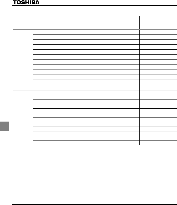
E6581381
I-6
9
■AIC, Fuse and Wire sizes
Voltage
class
Capacity of
applicable
motor
(kW)
Inverter model
AIC (A)
(Interrupting
capacity)
Fuse class and
current (A)
Input wire sizes of
power circuit
Out put wire sizes
of power circuit Earth
0.4 VFFS1-2004PM AIC 5000A J 3A max. AWG 14 AWG 14 AWG 14
0.75 VFFS1-2007PM AIC 5000A J 6A max. AWG 14 AWG 14 AWG 14
1.5 VFFS1-2015PM AIC 5000A J 10A max. AWG 14 AWG 14 AWG 14
2.2 VFFS1-2022PM AIC 5000A J 15A max. AWG 14 AWG 14 AWG 14
4.0 VFFS1-2037PM AIC 5000A J 25A max. AWG 12 AWG 10 AWG 12
5.5 VFFS1-2055PM AIC 22000A J 35A max. AWG 10 AWG 8 AWG 10
7.5 VFFS1-2075PM AIC 22000A J 45A max. AWG 8 AWG 8 AWG 10
11 VFFS1-2110PM AIC 22000A J 70A max. AWG 6 AWG 6 AWG 10
15 VFFS1-2150PM AIC 22000A J 90A max. AWG 4 AWG 4 AWG 10
18.5 VFFS1-2185PM AIC 22000A J 100 A max. AWG 4 AWG 3 AWG 8
22 VFFS1-2220PM AIC 22000A J 125A max. AWG 2 AWG 2 AWG 8
Three-phase
200V class
30 VFFS1-2300PM AIC 22000A J 175A max. AWG 1/0 AWG 1/0 AWG 6
0.4 VFFS1-4004PL AIC 5000A J 3A max. AWG 14 AWG 14 AWG 14
0.75 VFFS1-4007PL AIC 5000A J 3A max. AWG 14 AWG 14 AWG 14
1.5 VFFS1-4015PL AIC 5000A J 6A max. AWG 14 AWG 14 AWG 14
2.2 VFFS1-4022PL AIC 5000A J 10A max. AWG 14 AWG 14 AWG 14
4.0 VFFS1-4037PL AIC 5000A J 15A max. AWG 14 AWG 14 AWG 14
5.5 VFFS1-4055PL AIC 22000A J 20A max. AWG 14 AWG 14 AWG 14
7.5 VFFS1-4075PL AIC 22000A J 25A max. AWG 12 AWG 12 AWG 14
11 VFFS1-4110PL AIC 22000A J 35A max. AWG 10 AWG 10 AWG 10
15 VFFS1-4150PL AIC 22000A J 45A max. AWG 8 AWG 8 AWG 10
18.5 VFFS1-4185PL AIC 22000A J 60A max. AWG 8 AWG 8 AWG 10
22 VFFS1-4220PL AIC 22000A J 70A max. AWG 6 AWG 6 AWG 10
Three-phase
400V class
30 VFFS1-4300PL AIC 22000A J 90A max. AWG 4 AWG 4 AWG 10
9.2.4 Motor thermal protection
Selects the electronic thermal protection characteristics that fit with the ratings and characteristics of the motor. In
case of multi motor operation with one inverter, thermal relay should be connected to each motor.
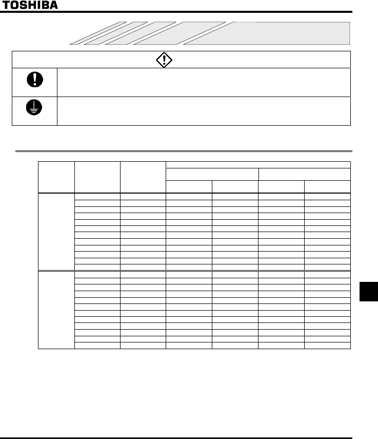
E6581381
J-1
10
10. Peripheral devices
Danger
Mandatory
•When using switchgear for the inverter, it must be installed in a cabinet.
Failure to do so can lead to risk of electric shock and can result in death or serious injury.
Be Grounded
•Connect earth cables securely.
Failure to do so can lead to risk of electric shock or fire in case of a failure or short-circuit or electric
leak.
10.1 Selection of wiring materials and devices
Wire size (See Note 4)
Power circuit
(mm2) Note 1)
Earth cable
(mm2)
Voltag e
class
Capacity of
applicable motor
(kW)
Inverter model
For IEC60364-5-
523/54
For JAPAN
JEAC8001-1995
For IEC60364-5-
523/54
For JAPAN
JEAC8001-1995
0.4 VFFS1-2004PM 1.5 2 2.5 2
0.75 VFFS1-2007PM 1.5 2 2.5 2
1.5 VFFS1-2015PM 1.5 2 2.5 2
2.2 VFFS1-2022PM 1.5 2 2.5 2
4.0 VFFS1-2037PM 2.5 2 2.5 2
5.5 VFFS1-2055PM 4 3.5 4 3.5
7.5 VFFS1-2075PM 6 5.5 6 3.5
11 VFFS1-2110PM 10 14 10 5.5
15 VFFS1-2150PM 16 14 16 5.5
18.5 VFFS1-2185PM 25 22 16 8
22 VFFS1-2220PM 25 38 16 8
Three-phase
200V class
30 VFFS1-2300PM 50 38 25 14
0.4 VFFS1-4004PL 1.5 2 2.5 2
0.75 VFFS1-4007PL 1.5 2 2.5 2
1.5 VFFS1-4015PL 1.5 2 2.5 2
2.2 VFFS1-4022PL 1.5 2 2.5 2
4.0 VFFS1-4037PL 1.5 2 2.5 2
5.5 VFFS1-4055PL 1.5 2 2.5 2
7.5 VFFS1-4075PL 1.5 2 2.5 2
11 VFFS1-4110PL 4 3.5 4 3.5
15 VFFS1-4150PL 6 5.5 6 3.5
18.5 VFFS1-4185PL 6 5.5 6 5.5
22 VFFS1-4220PL 10 8 10 5.5
Three-phase
400V class
30 VFFS1-4300PL 16 14 16 5.5
Note 1: Sizes of the wires connected to the input terminals R/L1, S/L2 and T/L3 and the output terminals U/T1,
V/T2 and W/T3 when the length of each wire does not exceed 30m.
Note 2: For the control circuit, use shielded wires 0.75 mm2 or more in diameter.
Note 3: For grounding, use a cable with a size equal to or larger than the above.
Note 4: The wire sizes specified in the above table apply to HIV wires (cupper wires shielded with an insulator
with a maximum allowable temperature of 75°C) used at an ambient temperature of 40°C or less.
Note 5: If there is a need to bring the inverter into UL compliance, use wires specified in Chapter 9.
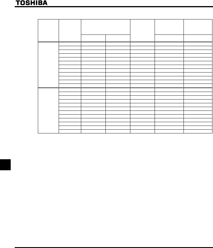
E6581381
J-2
10
■Selection of wiring devices
Input current (A) Molded case circuit
breaker (MCCB)
Earth leakage circuit
breaker (ELCB)
Magnetic contactor
(MC)
Voltage class
Capacity of
applicable
motor
(kW) 200V class:200V
400V class:380V
200V class:240V
400V class:480V
Inverter model
Rated current (A) Operational current(A)
AC-1
0.4 1.9 1.6 VFFS1-2004PM 3 25
0.75 3.3 2.7 VFFS1-2007PM 5 25
1.5 6.1 5.1 VFFS1-2015PM 10 25
2.2 8.7 7.3 VFFS1-2022PM 15 25
415.7 13.0 VFFS1-2037PM 30 25
5.5 20.8 17.3 VFFS1-2055PM 40 32
7.5 27.9 23.3 VFFS1-2075PM 50 40
11 42.1 34.4 VFFS1-2110PM 75 50
15 56.1 45.5 VFFS1-2150PM 100 80
18.5 67.3 55.8 VFFS1-2185PM 100 80
22 80.4 66.4 VFFS1-2220PM 125 100
Three-phase
200V class
30 113.3 89.5 VFFS1-2300PM 175 125
0.4 1.0 0.8 VFFS1-4004PL 325
0.75 1.7 1.4 VFFS1-4007PL 325
1.5 3.2 2.5 VFFS1-4015PL 525
2.2 4.6 3.6 VFFS1-4022PL 10 25
48.1 6.4 VFFS1-4037PL 15 25
5.5 10.9 8.6 VFFS1-4055PL 20 25
7.5 14.7 11.7 VFFS1-4075PL 30 32
11 21.1 16.8 VFFS1-4110PL 40 32
15 28.5 22.8 VFFS1-4150PL 50 40
18.5 34.8 27.8 VFFS1-4185PL 60 50
22 41.6 33.1 VFFS1-4220PL 75 80
Three-phase
400V class
Note 4)
30 56.7 44.7 VFFS1-42300PL 100 80
Note 1: Selections for use of the Toshiba 4-pole standard motor with power supply voltage of 200V/400V-50Hz.
Note 2: Choose the MCCB according to the power supply capacity.
For comply with UL and CSA standard, use the fuse certified by UL and CSA.
Note 3: When using on the motor side during commercial-power supply operation, choose the MC with class
AC-3 rated current for the motor rated current.
Note 4: Attach surge killers to the magnetic contactor and exciting coil of the relay.
Note 5: In the case the magnetic contactor (MC) with 2a-type auxiliary contacts is used for the control circuit,
raise the reliability of the contact by using 2a-type contacts in parallel connection.
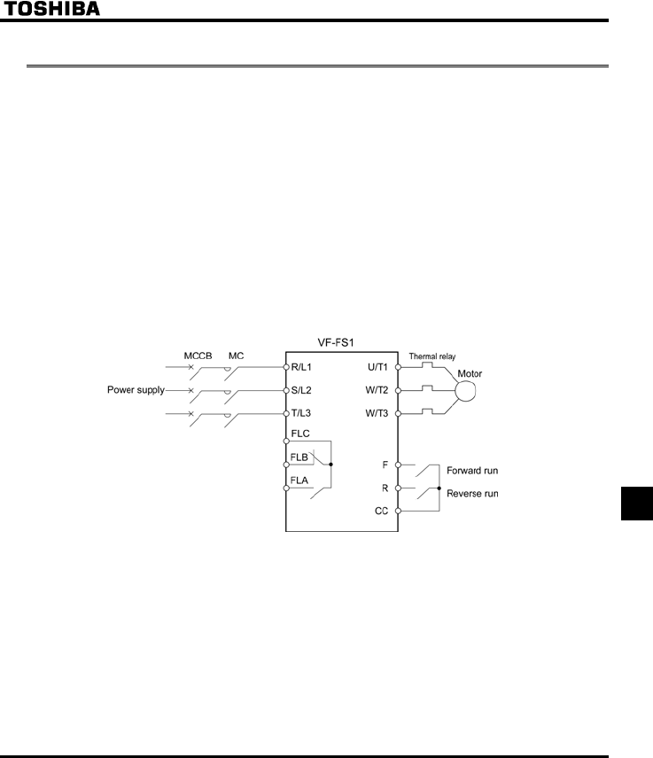
E6581381
J-3
10
10.2 Installation of a magnetic contactor
If using the inverter without installing a magnetic contactor (MC) in the primary circuit, use an MCCB (with a
power cutoff device) to open the primary circuit when the inverter protective circuit is activated.
■Magnetic contactor in the primary circuit
To detach the inverter from the power supply in any of the following cases, insert a magnetic contactor
(primary-side magnetic contactor) between the inverter and the power supply.
(1) If the motor overload relay is tripped
(2) If the protective detector (FL) built into the inverter is activated
(3) In the event of a power failure (for prevention of auto-restart)
When using the inverter with no magnetic contactor (MC) on the primary side, install a non-fuse circuit
breaker with a voltage tripping coil instead of an MC and adjust the circuit breaker so that it will be tripped if
the protective relay referred to above is activated. To detect a power failure, use an undervoltage relay or
the like.
Example of connection of a magnetic contactor in the primary circuit
Notes on wiring
•When frequently switching between start and stop, do not use the magnetic contactor on the primary side as
an on-off switch for the inverter.
Instead, stop and start the inverter by using terminals F and CC (forward run) or R and CC (reverse run).
•Be sure to attach a surge killer to the exciting coil of the magnetic contactor (MC).

E6581381
J-4
10
■Magnetic contactor in the secondary circuit
A magnetic contactor may be installed on the secondary side to switch controlled motors or supply
commercial power to the load when the inverter is out of operation.
Notes on wiring
•Be sure to interlock the magnetic contactor on the secondary side with the power supply to prevent commercial
power from being applied to the inverter output terminals.
•When installing a magnetic contactor (MC) between the inverter and the motor, avoid turning the magnetic
contactor on or off during operation. Turning the magnetic contactor on or off during operation causes a current
to rush into the inverter which could lead to malfunction.
10.3 Installation of an overload relay
1) The VF-FS1 inverter has an electronic-thermal overload protective function.
In the following cases, however, an overload relay suitable for the adjustment of the motor electronic
thermal protection level (VJT) and appropriate to the motor used should be installed between the inverter
and the motor.
•When using a motor with a current rating different to that of the corresponding Toshiba general-purpose
motor
•When operating a single motor with an output smaller than that of the applicable standard motor or more
than one motor simultaneously.
2) When using the VF-FS1 inverter to operate a constant-torque motor, such as the Toshiba VF motor, adjust
the protection characteristic of the electronic thermal protection unit (NO) to the VF motor use.
3) It is recommended to use a motor with a thermal relay embedded in the motor coil to give sufficient
protection to the motor, especially when it runs in a low-speed range.
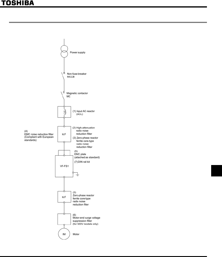
E6581381
J-5
10
10.4 Optional external devices
The following external devices are optionally available for the VF-FS1 series of inverters.
(8) Parameter writer
(9) Extension panel
(10) Internal LonWorks® communication circuit board
(11) Internal Metasys® N2 communication circuit board
(12) Internal Siemens APOGEETM FLN communication
circuit board
(13) Internal BACnet® communication circuit board
(14) USB communication converter unit
(15) Remote panel
(16) Application control unit
(17) Conduit pipe attachment kit
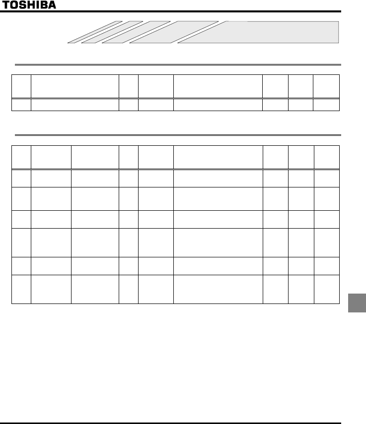
E6581381
K-1
11
11.Table of parameters and data
11.1 User parameters
Title Function Unit
Minimum
setting unit
Panel/Commun
ication
Adjustment range Default
setting
User
setting Reference
HE Operation frequency of operation
panel
Hz 0.1/0.01 NN-WN 0.0 3.2
11.2 Basic parameters
Title Communication
No. Function Unit
Minimum
setting unit
Panel/Commun
ication
Adjustment range Default
setting
User
setting Reference
CWH - Wizard function - - The wizard function refers to the
special function of calling up ten
frequently used parameters.
- 4.2.4
6.20.7
CWJ - History function - - Displays parameters in groups of five
in the reverse order to that in which
their settings were changed.
* (Possible to edit)
- 4.2.5
CW 0000 Automatic
acceleration/
deceleration
- - 0: Disabled (manual)
1: Automatic
2: Automatic (only at acceleration)
0 5.1.1
CW 0040 Parameter setting
macro function
- - 0: Disabled
1: Coast stop
2: 3-wire operation
3: External input UP/DOWN setting
4: 4-20 mA current input operation
05.2
EOQF 0003 Command mode
selection
- - 0: Terminal board
1: Operation panel
2: Serial communication
05.3
7.2
HOQF 0004 Frequency setting
mode selection 1
--1: VIA
2: VIB
3: Operation panel
4: Serial communication
5: UP/DOWN from external contact
15.3
6.5.1
7.1

E6581381
K-2
11
Title Communication
No. Function Unit
Minimum
setting unit
Panel/Commun
ication
Adjustment range Default
setting
User
setting Reference
HOUN 0005 Meter selection - - 0: Output frequency
1: Output current
2: Set frequency
3: DC voltage
4: Output voltage command value
5: Input power
6: Output power
7: Torque
8: Torque current
9: Motor cumulative load factor
10: Inverter cumulative load factor
11: - (do not select)
12: Frequency setting value (after
PID)
13: VIA Input value
14: VIB Input value
15: Fixed output 1 (Output current:
100%)
16: Fixed output 2 (Output current:
50%)
17: Fixed output 3 (Supposition
output at HOUN=17)
18: Serial communication data
19: For adjustments (HO set value is
displayed.)
05.4
HO 0006 Meter adjustment - - - -
V[R 0007 Default setting - - 0: -
1: 50Hz default setting
2: 60Hz default setting
3: Default setting (Initialization)
4: Trip record clear
5: Cumulative operation time clear
6: Initialization of type information
7: Save user setting parameters
8. Call user-defined parameters
9. Cumulative fan operation time
record clear
0 4.2.7
4.2.8
5.5
HT 0008 Forward/reverse
run selection
(Operation panel
operation)
- - 0: Forward run
1: Reverse run
2: Forward run (F/R switching
possible)
3: Reverse run (F/R switching
possible)
05.6
CEE 0009 Acceleration time
1
S 0.1/0.1 0.0-3200 *2 5.1.2
FGE 0010 Deceleration time
1
S 0.1/0.1 0.0-3200 *2
HJ 0011 Maximum
frequency
Hz 0.1/0.01 30.0-200.0 80.0 5.7
WN 0012 Upper limit
frequency
Hz 0.1/0.01 0.5-HJ 50.0 (WP)
60.0 (WN)
5.8
NN 0013 Lower limit
frequency
Hz 0.1/0.01 0.0-WN 0.0
XN 0014 Base frequency 1 Hz 0.1/0.01 25.0-200.0 50.0 (WP)
60.0 (WN)
5.9
XNX 0409 Base frequency
voltage 1
V 1/0.1 50-330 (200V class)
50-660 (400V class)
*1 5.9
6.12.5
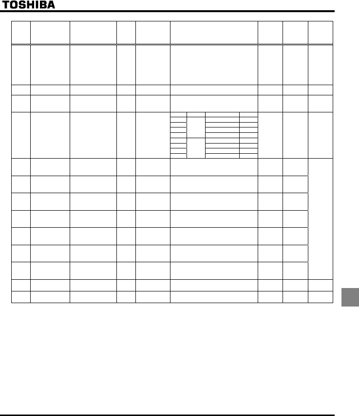
E6581381
K-3
11
Title Communication
No. Function Unit
Minimum
setting unit
Panel/Commun
ication
Adjustment range Default
setting
User
setting Reference
RV 0015 V/F control mode
selection
- - 0: V/F constant
1: Variable torque
2: Automatic torque boost control
3: Vector control
4: Energy-saving
5: - (Do not select)
6: PM motor control
25.10
XD 0016 Torque boost 1 % 0.1/0.1 0.0-30.0 * 2 5.11
VJT 0600 Motor electronic-
thermal protection
level 1
%
(A)
1/1 10-100 100 5.12
6.17.1
Setting Overload protection OL stall
0{×
1{{
2××
3
Standard
motor
×{
4{×
5{{
6××
QNO 0017 Electronic-thermal
protection
characteristic
selection *3
--
7
VF motor
×{
05.12
UT 0018 Preset-speed
operation
frequency 1
Hz 0.1/0.01 NN-WN 15.0
UT 0019 Preset-speed
operation
frequency 2
Hz 0.1/0.01 NN-WN 20.0
UT 0020 Preset-speed
operation
frequency 3
Hz 0.1/0.01 NN-WN 25.0
UT 0021 Preset-speed
operation
frequency 4
Hz 0.1/0.01 NN-WN 30.0
UT 0022 Preset-speed
operation
frequency 5
Hz 0.1/0.01 NN-WN 35.0
UT 0023 Preset-speed
operation
frequency 6
Hz 0.1/0.01 NN-WN 40.0
UT 0024 Preset-speed
operation
frequency 7
Hz 0.1/0.01 NN-WN 45.0
5.13
H - Extended
parameters
- - - - - 4.2.2
ITW - Automatic edit
function
- - - - - 4.2.3
*1 : 230 (WP/WN type), 400 (WP type), 460 (WN type)
*2 : Default values vary depending on the capacity. ⇒ See the table of page K-14.
*3 : { : valid, × : invalid
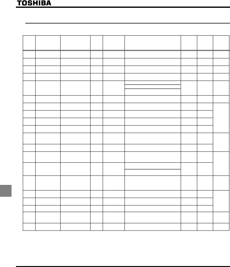
E6581381
K-4
11
11.3 Extended parameters
•Input/output parameters 1
Title Communication
No. Function Unit
Minimum
setting unit
Panel/Commun
ication
Adjustment range Default
setting
User
setting Reference
H 0100 Low-speed signal
output frequency
Hz 0.1/0.01 0.0-HJ 0.0 6.1.1
H 0101 Speed reach
setting frequency
Hz 0.1/0.01 0.0-HJ 0.0 6.1.3
H 0102 Speed reach
detection band
Hz 0.1/0.01 0.0-HJ 2.5 6.1.2
H 0108 Always active
function selection 1
--0-71 (No function) 0 6.3.1
0: VIA - analog input
1: VIA - contact input (Sink)
H 0109 Analog/contact
input function
selection (VIA
terminal)
--
2: VIA - contact input (Source)
0 6.2.1
H 0110 Always-active
function selection 2
- - 0-71 (ST) 1 6.3.1
H 0111 Input terminal
selection 1 (F)
- - 0-71 (F) 2
H 0112 Input terminal
selection 2 (R)
- - 0-71 (R) 3
H 0113 Input terminal
selection 3 (RES)
- - 0-71 (RES) 10
H 0118 Input terminal
selection 8 (VIA) --
0-71 (SS1) 6
6.3.2
H 0130
Output terminal
selection 1A
(RY-RC)
--
0-255 (LOW) 4
H 0132 Output terminal
selection 3 (FL)
- - 0-255 (FL) 10
6.3.3
H 0137 Output terminal
selection 1B
(RY-RC)
- - 0-255 (always ON) 255 6.3.4
0: H and H
H 0139 Output terminal
logic selection
(RY-RC)
--
1: H or H
0
H 0167 Frequency
command
agreement
detection range
Hz 0.1/0.01 0.0-HJ 2.5 6.3.5
H 0170 Base frequency 2 Hz 0.1/0.01 25.0-200.0 50.0 (WP)
60.0 (WN)
H 0171 Base frequency
voltage 2
V 1/0.1 50-330 (200V class)
50-660 (400V class)
* 2
H 0172 Torque boost 2 % 0.1/0.1 0.0-30.0 * 1
6.4.1
H 0173 Motor electronic-
thermal protection
level 2
%
(A)
1/1 10-100 100 5.12
6.4.1
H 0185 Stall prevention
level 2
%
(A)
1/1 10-110,
111 (disab led)
110 6.4.1
6.17.2
*1 : Default values vary depending on the capacity. ⇒ See the table of page K-14.
*2 : 230 (WP/WN type), 400 (WP type), 460 (WN type)

E6581381
K-5
11
•Frequency parameters
Title Communication
No. Function Unit
Minimum
setting unit
Panel/Commun
ication
Adjustment range Default
setting
User
setting Reference
0: HOQF (Switchable to H by
terminal input)
H 0200 Frequency priority
selection
--
1: HOQF (Switchable to H at
less than 1.0Hz of designated
frequency)
0 6.5.1
7.1
H 0201 VIA input point 1
setting
% 1/1 0-100 0
H 0202 VIA input point 1
frequency
Hz 0.1/0.01 0.0-200.0 0.0
H 0203 VIA input point 2
setting
% 1/1 0-100 100
H 0204 VIA input point 2
frequency
Hz 0.1/0.01 0.0-200.0 50.0 (WP)
60.0 (WN)
6.5.2
H 0207 Frequency setting
mode
selection 2
--1: VIA
2: VIB
3: Operation panel
4: Serial communication
5: UP/DOWN from external contact
2 6.3.5
6.5.1
7.1
H 0210 VIB input point 1
setting
% 1/1 0-100 0
H 0211 VIB input point 1
frequency
Hz 0.1/0.01 0.0-200.0 0.0
H 0212 VIB input point 2
setting
% 1/1 0-100 100
H 0213 VIB input point 2
frequency
Hz 0.1/0.01 0.0-200.0 50.0 (WP)
60.0 (WN)
6.5.2
H 0240 Starting frequency
setting
Hz 0.1/0.01 0.5-10.0 0.5 6.6.1
H 0241 Operation starting
frequency
Hz 0.1/0.01 0.0-HJ 0.0 6.6.2
H 0242 Operation starting
frequency
hysteresis
Hz 0.1/0.01 0.0-HJ 0.0
H 0250 DC braking
starting frequency
Hz 0.1/0.01 0.0-HJ 0.0
H 0251 DC braking
current
%(A) 1/1 0-100 50
H 0252 DC braking time s 0.1/0.1 0.0-20.0 1.0
6.7.1
H 0256 Auto-stop in case
of lower-limit
frequency
continuous
operation time
s 0.1/0.1 0.0: Disabled
0.1-600.0
0.0 6.8
H 0264 External contact
input - UP
response time
s 0.1/0.1 0.0-10.0 0.1
H 0265 External contact
input - UP
frequency steps
Hz 0.1/0.01 0.0-HJ 0.1
6.5.3
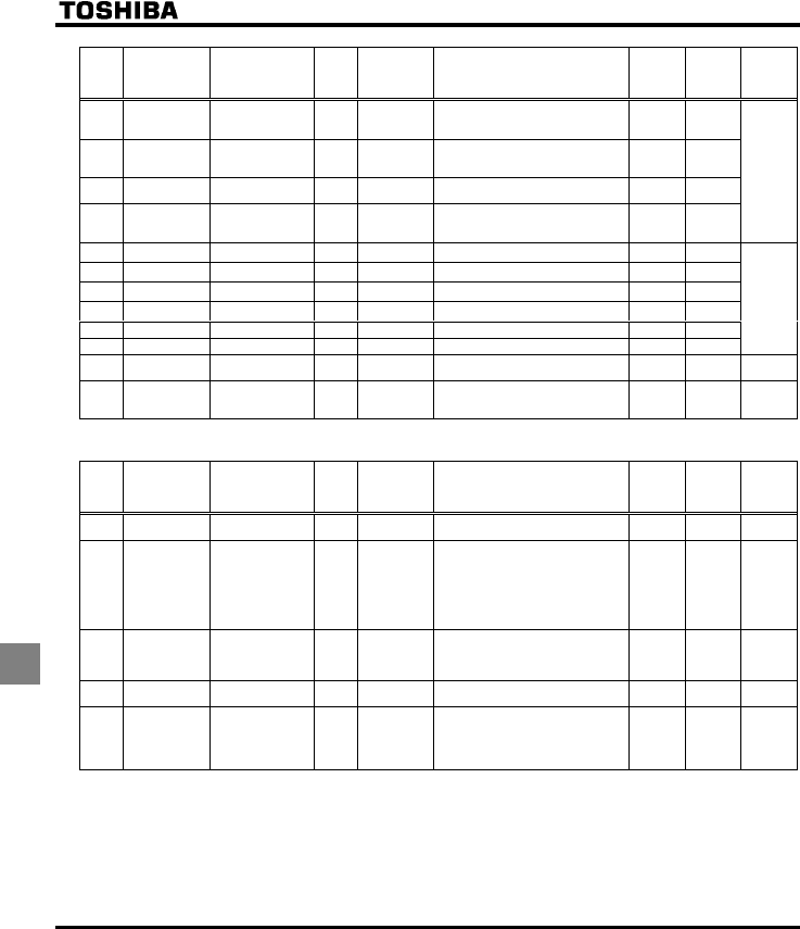
E6581381
K-6
11
Title Communication
No. Function Unit
Minimum
setting unit
Panel/Commun
ication
Adjustment range Default
setting
User
setting Reference
H 0266 External contact
input - DOWN
response time
s 0.1/0.1 0.0-10.0 0.1 6.5.3
H 0267 External contact
input - DOWN
frequency steps
Hz 0.1/0.01 0.0-HJ 0.1
H 0268 Initial UP/DOWN
frequency
Hz 0.1/0.01 NNWN 0.0
H 0269 Change of the
initial up/down
frequency
- - 0: Not changed
1: Setting of H changed when
power is turned off
1
H 0270 Jump frequency 1 Hz 0.1/0.01 0.0-HJ 0.0 6.9
H 0271 Jumping width 1 Hz 0.1/0.01 0.0-30.0 0.0
H 0272 Jump frequency 2 Hz 0.1/0.01 0.0-HJ 0.0
H 0273 Jumping width 2 Hz 0.1/0.01 0.0-30.0 0.0
H 0274 Jump frequency 3 Hz 0.1/0.01 0.0-HJ 0.0
H 0275 Jumping width 3 Hz 0.1/0.01 0.0-30.0 0.0
H 0294 Forced fire-speed
setting frequency
Hz 0.1/0.01 NN-WN 50.0 6.18
H 0295 Bumpless
operation
selection
- - 0: Disabled
1: Enabled
16.10
•Operation mode parameters
Title Communication
No. Function Unit
Minimum
setting unit
Panel/Commun
ication
Adjustment range Default
setting
User
setting Reference
H 0300 PWM carrier
frequency
kHz 0.1/0.1 6.0 - 16.0 * 1 6.11
H 0301 Auto-restart
control selection
- - 0: Disabled
1: At auto-restart after momentary
stop
2: When turning ST-CC on or off
3: At auto-restart or when turning ST-
CC on or off
4: At start-up
0 6.12.1
H 0302 Instantaneous
power failure
coast stop
selection
- - 0: Disabled
1: - (Do not select)
2: Coast stop
0 6.12.2
H 0303 Retry selection
(number of times)
Times 1/1 0: Disabled
1-10
0 6.12.3
H 0305 Overvoltage limit
operation
(Slowdown stop
mode selection)
- - 0: Enabled
1: Disabled
2: Enabled (Quick deceleration)
3: Enabled (Dynamic quick
deceleration)
2 6.12.4
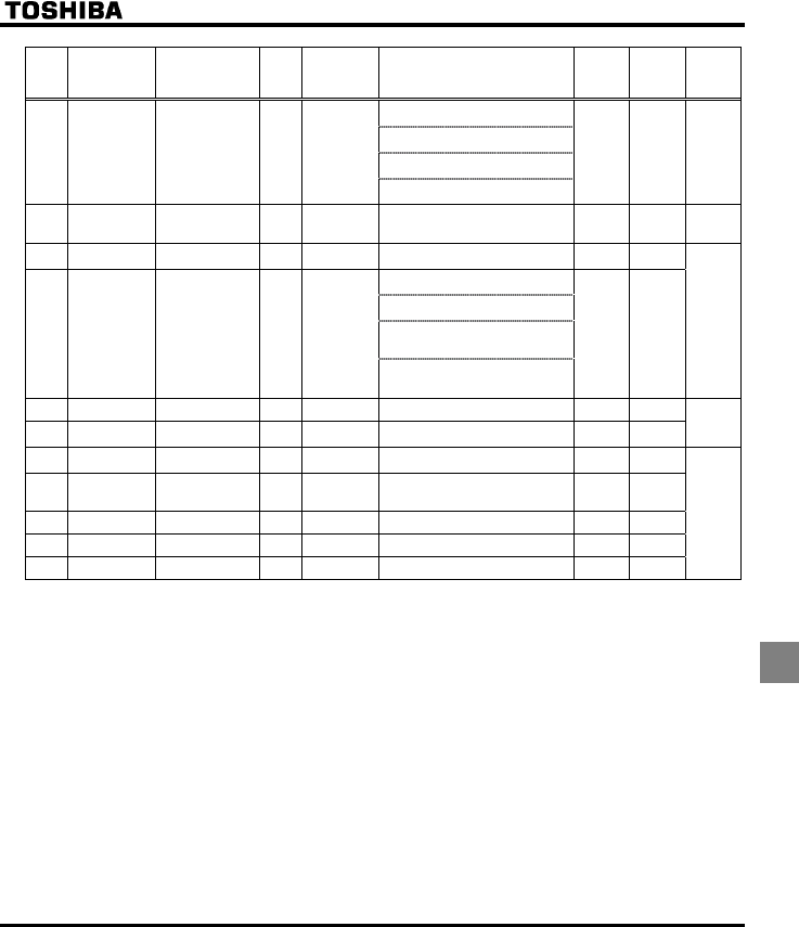
E6581381
K-7
11
Title Communication
No. Function Unit
Minimum
setting unit
Panel/Commun
ication
Adjustment range Default
setting
User
setting Reference
0: Supply voltage uncorrected, output
voltage limited
1: Supply voltage corrected, output
voltage limited
2: Supply voltage uncorrected, output
voltage unlimited
H 0307 Supply voltage
correction
(limitation of
output voltage)
--
3: Supply voltage corrected, output
voltage unlimited
2 6.12.5
H 0311 Reverse-run
prohibition
- - 0: Forward/reverse run permitted
1: Reverse run prohibited
2: Forward run prohibited
0 6.12.6
H 0312 Random mode - - 0: Disabled
1: Automatic setting
06.11
0: Carrier frequency not reduced
automatically
1: Carrier frequency reduced
automatically
2: Carrier frequency not reduced
automatically
Support for 400V models
H 0316 Carrier frequency
control mode
selection
--
3: Carrier frequency reduced
automatically
Support for 400V models
1
H 0320 Droop gain %1/1 0-100 0 6.13
H 0323 Droop insensitive
torque band
%1/1 0-100 10
H 0359 PID control
waiting time
s 1/1 0-2400 0 6.14
H 0360 PID control - - 0: Disabled,
1: Enabled (Feedback: VIA)
2: Enabled (Feedback: VIB)
0
H 0362 Proportional gain - 0.01/0.01 0.01-100.0 0.30
H 0363 Integral gain - 0.01/0.01 0.01-100.0 0.20
H 0366 Differential gain - 0.01/0.01 0.00-2.55 0.00
*1 : Default values vary depending on the capacity. ⇒ See the table of page K-14.
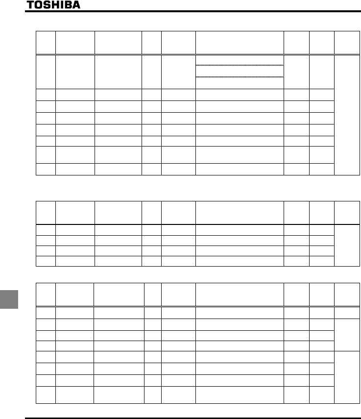
E6581381
K-8
11
•Torque boost parameters 1
Title Communication
No. Function Unit
Minimum
setting unit
Panel/Commun
ication
Adjustment range Default
setting
User
setting Reference
0: Auto-tuning disabled
1: Application of individual settings of
H (after execution: 0)
H 0400 Auto-tuning - -
2: Auto-tuning enabled
(after execution: 0)
0
H 0401 Slip frequency
gain
% 1/1 0-150 50
H 0402 Automatic torque
boost value
% 0.1/0.1 0.0-30.0 * 1
H 0415 Motor rated
current
A 0.1/0.1 0.1-200.0 * 1
H 0416 Motor no-load
current
% 1/1 10-100 * 1
H 0417 Motor rated speed min-1 1/1 100-15000 * 1
H 0418 Speed control
response
coefficient
- 1/1 1-150 40
H 0419 Speed control
stability coefficient
- 1/1 1-100 20
5.10
6.15.1
*1 : Default values vary depending on the capacity. ⇒ See the table of page K-14.
•Input/output parameters 2
Title Communication
No. Function Unit
Minimum
setting unit
Panel/Commun
ication
Adjustment range Default
setting
User
setting Reference
H 0470 VIA input bias - - 0-255 128
H 0471 VIA input gain - - 0-255 148
H 0472 VIB input bias - - 0-255 128
H 0473 VIB input gain - - 0-255 148
6.5.4
•Torque boost parameters 2
Title Communication
No. Function Unit
Minimum
setting unit
Panel/Commun
ication
Adjustment range Default
setting
User
setting Reference
H 0480 Exciting current
coefficient
% 1/1 100-130 100 5.10
6.15.2
H 0481 Power supply
compensation filter
- 1 0-9999 0 6.17.16
H 0482 Inhibitor filter - 1 0-9999 442
H 0483 Inhibitor gain - 0.1 0.0-300.0 100.0
H 0485 Stall prevention
control coefficient 1
- 1/1 10-250 100 5.10
6.15.2
H 0492 Stall prevention
control coefficient 2
- 1/1 50-150 100
H 0494 Motor adjustment
coefficient
- 1/1 0-200 * 1
H 0495 Maximum voltage
adjustment
coefficient
% 1/1 90-120 104
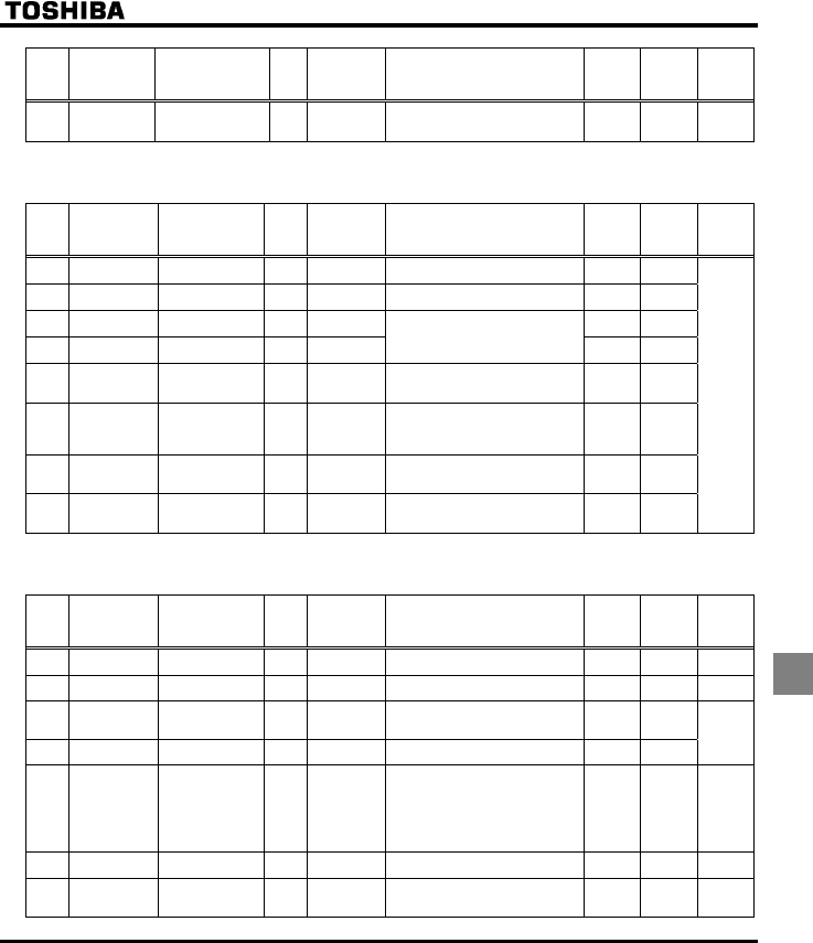
E6581381
K-9
11
Title Communication
No. Function Unit
Minimum
setting unit
Panel/Commun
ication
Adjustment range Default
setting
User
setting Reference
H 0496 Waveform switching
adjustment
coefficient
kHz 0.1/0. 1 0.1-14.0 14.0 5.10
6.15.2
*1 : Default values vary depending on the capacity. ⇒ See the table of page K-14.
•Acceleration/deceleration time parameters
Title Communication
No. Function Unit
Minimum
setting unit
Panel/Commun
ication
Adjustment range Default
setting
User
setting Reference
H 0500 Acceleration time
2
s 0.1/0.1 0.0-3200 * 1
H 0501 Deceleration time
2
s 0.1/0.1 0.0-3200 * 1
H 0502 Acceleration/decel
eration 1 pattern
-- 0
H 0503 Acceleration/decel
eration 2 pattern
--
0: Linear
1: S-pattern 1
2: S-pattern 2 0
H 0504 Selecting an
acceleration/decel
eration pattern
- - 1: Acceleration/deceleration 1
2: Acceleration/deceleration 2
1
H 0505 Acceleration/decel
eration 1 and 2
switching
frequency
Hz 0.1/0.01 0.0-WN 0.0
H 0506 S-pattern lower-
limit adjustment
amount
% 1/1 0-50 10
6.16
H 0507 S-pattern upper-
limit adjustment
amount
% 1/1 0-50 10
*1 : Default values vary depending on the capacity. ⇒ See the table of page K-14.
•Protection parameters
Title Communication
No. Function Unit
Minimum
setting unit
Panel/Commun
ication
Adjustment range Default
setting
User
setting Reference
H 0601 Stall prevention
level 1
%
(A)
1/1 10-110,
111 (disab led)
110 6.17.2
H 0602 Inverter trip
retention selection
- - 0: Canceled with the power off
1: Still retained with the power off
0 6.17.3
H 0603 Emergency stop
selection
- - 0: Coast stop
1: Slowdown stop
2: Emergency DC braking
06.17.4
H 0604 Emergency DC
braking time
s0.1/0.1 0.0-20.0 1.0
H 0605 Output phase
failure detection
mode selection
--0: Disabled
1: At start-up (only one time after
power is turned on)
2: At start-up (each time)
3: During operation
4: At start-up + during operation
5: Detection of cutoff on output side
06.17.5
H 0607 Motor 150%-
overload time limit
s 1/1 10-2400 300 6.17.1
H 0608 Input phase failure
detection mode
selection
- - 0: Disabled, 1: Enabled 1 6.17.6

E6581381
K-10
11
Title Communication
No. Function Unit
Minimum
setting unit
Panel/Commun
ication
Adjustment range Default
setting
User
setting Reference
H 0609 Small current
detection current
hysteresis
% 1/1 1-20 10
H 0610 Small current
trip/alarm
selection
- - 0: Alarm only
1: Tripping
0
H 0611 Small current
detection current
%
(A)
1/1 0-100 0
H 0612 Small current
detection time
s 1/1 0-255 0
6.17.7
H 0613 Detection of
output short-circuit
during start-up
- - 0: Each time (standard pulse)
1: Only one time after power is turned
on (standard pulse)
2: Each time (short-time pulse)
3: Only one time after power is turned
on (short-time pulse)
0 6.17.8
H 0615 Over-torque
trip/alarm
selection
- - 0: Alarm only
1: Tripping
0
H 0616 Over-torque
detection level
%1/1 0-200 130
H 0618 Over-torque
detection time
s 0.1/0.1 0.0-10.0 0.5
6.17.9
H 0619 Over-torque
detection level
hysteresis
% 1/1 0-100 10
H 0621 Cumulative
operation time
alarm setting
100
Time
0.1/0.1
(=10 hours)
0.0-999.9 610.0 6.17.10
H 0626 Overvoltage limit
operation level
%1/1 100-150 140 6.12.4
H 0627 Undervoltage
trip/alarm
selection
- - 0: Alarm only
(detection level below 60%)
1: Tripping
(detection level below 60%)
2: Alarm only
(detection level below 50%,
input reactor necessary)
0 6.17.12
H 0632 Thermal memory
selection
- - 0: Disabled
1: Enabled
0 6.17.1
H 0633 Trip at VIA low
level input mode
%1/1 0: Disabled, 1-100 0 6.17.13
H 0634 Annual average
ambient
temperature (For
parts replacement
alarms)
- - 1: -10 to +10°C
2: 11-20°C
3: 21-30°C
4: 31-40°C
5: 41-50°C
6: 51-60°C
3 6.17.14
H 0645 PTC thermal
selection
- - 0: Disabled
1: Enabled (trip mode)
2: Enabled (alarm mode)
0 6.17.15
H 0646 PTC detection
resistor value
Ω
1/1 100-9999 3000
H 0650 Forced fire-speed
control selection
- - 0: Disabled
1: Enabled
06.18

E6581381
K-11
11
•Output parameters
Title Communication
No. Function Unit
Minimum
setting unit
Panel/Commun
ication
Adjustment range Default
setting
User
setting Reference
H 0691 Inclination
characteristic of
analog output
- - 0: Negative inclination (downward
slope)
1: Positive inclination (upward slope)
1 6.19.1
H 0692 Bias of analog
output
%1/10-100 0
•Operation panel parameters
Title Communication
No. Function Unit
Minimum
setting unit
Panel/Commun
ication
Adjustment range Default
setting
User
setting Reference
H 0700 Prohibition of
parameter change
- - 0: Permitted
1: Prohibited
0 6.20.1
H 0701 Current/voltage
display mode
--0: %
1: A (ampere)/V (volt)
0 6.20.2
H 0702 Frequency free
unit magnification
Times 0.01/0.01 0.00: Free unit display disabled
(display of frequency)
0.01-200.0
0.00
H 0705 Inclination
characteristic of
free unit display
- - 0: Negative inclination (downward
slope)
1: Positive inclination (upward slope)
1
H 0706 Bias of free unit
display
Hz 0.01/0.01 0.00-HJ 0.00
6.20.3
H 0707 Free step 1
(pressing a panel
key once)
Hz 0.01/0.01 0.00: Disabled
0.01-HJ
0.00
H 0708 Free step 2 (panel
display)
- 1/1 0: Disabled
1-255
0
6.20.4
H 0710 Standard monitor
display selection
- - 0: Operation frequency (Hz/free
unit/step)
1: Frequency command (Hz/free
unit/step)
2: Output current (%/A)
3: Inverter rated current (A)
4: Inverter load factor (%)
5: Output power (kW)
6: Frequency command after PID
control (Hz/free unit/step)
7: Optional item specified from an
external control unit
8: Output speed
9: Communication counter
10: Normal state communication
counter
0 6.20.5
H 0721 Selection of
operation panel
stop pattern
- - 0: Slowdown stop
1: Coast stop
0 6.20.6
H 0730 Prohibition of
frequency setting
on the operation
panel (HE)
- - 0: Permitted
1: Prohibited
0 6.20.1
H 0732 Prohibition of
panel local/remote
operation
(LOC/REM key)
- - 0: Permitted
1: Prohibited
0
H 0733 Prohibition of
panel operation
(RUN/STOP keys)
- - 0: Permitted
1: Prohibited
0
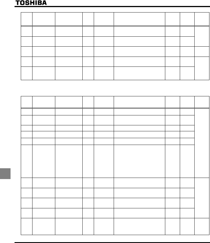
E6581381
K-12
11
Title Communication
No. Function Unit
Minimum
setting unit
Panel/Commun
ication
Adjustment range Default
setting
User
setting Reference
H 0734 Prohibition of
panel emergency
stop operation
- - 0: Permitted
1: Prohibited
0 6.20.1
H 0735 Prohibition of
panel reset
operation
- - 0: Permitted
1: Prohibited
0
H 0738 Head of
parameter display
selection
--0: AUF
1: AUH
0 6.20.7
H 0748 Integral output
power retention
selection
- - 0: Disabled
1: Enabled
1 6.20.8
H 0749 Display unit
selection for
integral output
power
- - 0: 1=1kWh
1: 0.1=1kWh
2: 0.01=1kWh
3: 0.001=1kWh
*1
*1 : Default values vary depending on the capacity. ⇒ See the table of page K-14.
•Communication parameters
Title Communication
No. Function Unit
Minimum
setting unit
Panel/Commun
ication
Adjustment range Default
setting
User
setting Reference
H 0800 Communication
rate
- - 0: 9600bps
1: 19200bps
1
H 0801 Parity - - 0: NON (No parity)
1: EVEN (Even parity)
2: ODD (Odd parity)
1
H 0802 Inverter number - 1/1 0-247 0
H 0803 Communication
error trip time
s 1/1 0: Disabled
1-100
0
H 0805 Communication
waiting time
s 0.01/0.01 0.00: Regular communication
0.01-2.00
0.00
H 0806 Setting of master
and slave for
communication
between inverters
- - 0: Slave (0 Hz command issued in
case the master inverter fails)
1: Slave (Operation continued in case
the master inverter fails)
2: Slave (Emergency stop tripping in
case the master inverter fails)
3: Master (transmission of frequency
commands)
4: Master (transmission of output
frequency signals)
0
6.21
H 0811 Communication
command point 1
setting
% 1/1 0-100 0
H 0812 Communication
command point 1
frequency
Hz 0.1/0.01 0.0-200.0 0.0
H 0813 Communication
command point 2
setting
% 1/1 0-100 100
H 0814 Communication
command point 2
frequency
Hz 0.1/0.01 0.0-200.0 50.0 (WP)
60.0 (WN)
6.5.2
6.21
H 0829 Selection of
communication
protocol
- - 0: Toshiba inverter protocol
1: ModbusRTU protocol
2: Metasys N2 protocol
3: APOGEE FLN protocol
4: BAC-net protocol
06.21
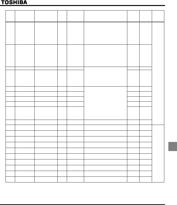
E6581381
K-13
11
Title Communication
No. Function Unit
Minimum
setting unit
Panel/Commun
ication
Adjustment range Default
setting
User
setting Reference
H 0851 Operation at
communication error
by disconnection
- - 0:Inverter stop, communication
command, frequency mode open
(by EOQF, HOQF)
1:None (continued operation)
2:Deceleration stop
3:Coast stop
4:Communication error (GTT trip)
or Network error (GTT trip)
46.21
H 0856 Number of motor
poles for
communication
- - 1: 2 poles
2: 4 poles
3: 6 poles
4: 8 poles
5: 10 poles
6: 12 poles
7: 14 poles
8: 16 poles
2
H 0870 Block write data 1 - - 0
H 0871 Block write data 2 - -
0: No selection
1: Command 1
2: Command 2
3: Frequency command
4: Output data on the terminal board
5: Analog output for communications
6: Motor speed command
0
H 0875 Block read data 1 - - 0
H 0876 Block read data 2 - - 0
H 0877 Block read data 3 - - 0
H 0878 Block read data 4 - - 0
H 0879 Block read data 5 - -
0: No selection
1: Status information
2: Output frequency
3: Output current
4: Output voltage
5: Alarm information
6: PID feedback value
7: Input terminal board monitor
8: Output terminal board monitor
9: VIA terminal board monitor
10: VIB terminal board monitor
11: Output motor speed monitor
0
H 0880 Free notes - 1/1 0-65535 0
H 0890 Parameter for
option 1
- 1/1 0-65535 0
H 0891 Parameter for
option 2
- 1/1 0-65535 0
6.22
H 0892 Parameter for
option 3
- 1/1 0-65535 0
H 0893 Parameter for
option 4
- 1/1 0-65535 0
H 0894 Parameter for
option 5
- 1/1 0-65535 0
H 0895 Parameter for
option 6
- 1/1 0-65535 0
H 0896 Parameter for
option 7
- 1/1 0-65535 0
H 0897 Parameter for
option 8
- 1/1 0-65535 0
H 0898 Parameter for
option 9
- 1/1 0-65535 0
H 0899 Parameter for
option 10
- 1/1 0-65535 0
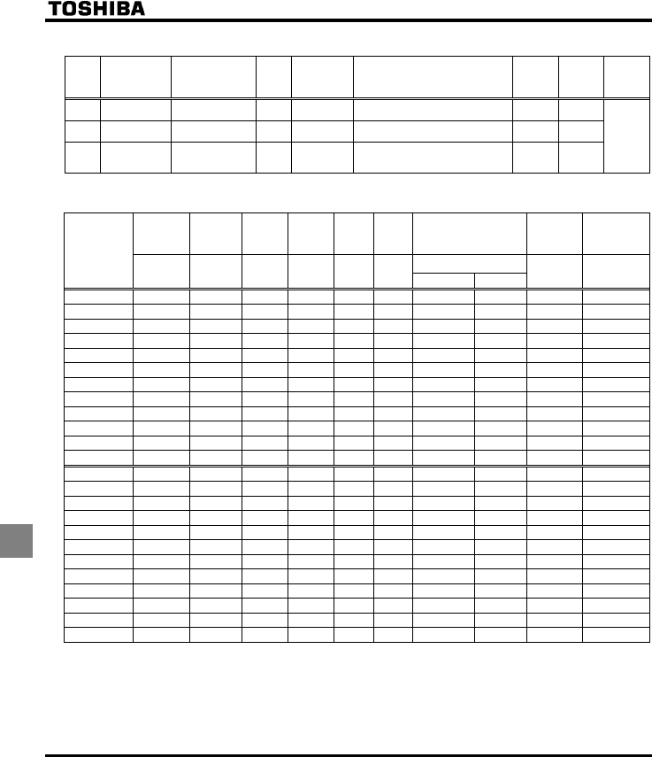
E6581381
K-14
11
•PM motor parameters
Title Communication
No. Function Unit
Minimum
setting unit
Panel/Commun
ication
Adjustment range Default
setting
User
setting Reference
H 0910 Step-out detection
current level
%
(A)
1/1 10-150 100
H 0911 Step-out detection
time
s 0.1/0.1 0.0: No detection
0.1-25.0
0.0
H 0912 High-speed torque
adjustment
coefficient
- 0.01/0.01 0.00-650.0 0.00
6.23
■Default settings by inverter rating
Acceleration
Deceleration
time
Torque
boost value
1/2
PWM
carrier
frequency
Automatic
torgue
boost
value
Motor
rated
current
Motor
no-load
current
Motor rated speed
Motor
adjustment
coefficient
Display unit
selection for
integral
output power
H (min-1)
Inverter type
CEE, FGE,
H,
H
XD/H
(%)
H
(kHz)
H
(%)
H
(A)
H
(%) WN/V[R: 2 WP/V[R: 1
H H
VFFS1-2004PM 10 6.0 12.0 6.2 2.0 65 1680 1400 90 0
VFFS1-2007PM 10 6.0 12.0 5.8 3.4 60 1690 1408 80 0
VFFS1-2015PM 10 6.0 12.0 4.3 6.2 55 1690 1408 70 0
VFFS1-2022PM 10 5.0 12.0 4.1 8.9 52 1680 1400 70 0
VFFS1-2037PM 10 5.0 12.0 3.4 14.8 48 1690 1408 70 1
VFFS1-2055PM 10 4.0 12.0 3.0 21.0 46 1730 1441 70 1
VFFS1-2075PM 10 3.0 12.0 2.5 28.2 43 1730 1441 70 1
VFFS1-2110PM 10 2.0 12.0 2.3 40.6 41 1730 1441 60 1
VFFS1-2150PM 10 2.0 12.0 2.0 54.6 38 1730 1441 50 1
VFFS1-2185PM 30 2.0 8.0 2.0 68.0 36 1750 1458 50 1
VFFS1-2220PM 30 2.0 8.0 1.8 80.0 34 1750 1458 50 1
VFFS1-2300PM 30 2.0 8.0 1.8 108.0 32 1745 1454 50 1
VFFS1-4004PL 10 6.0 12.0 6.2 1.0 65 1680 1400 90 0
VFFS1-4007PL 10 6.0 12.0 5.8 1.7 60 1690 1408 80 0
VFFS1-4015PL 10 6.0 12.0 4.3 3.1 55 1690 1408 70 0
VFFS1-4022PL 10 5.0 12.0 4.1 4.5 52 1680 1400 70 0
VFFS1-4037PL 10 5.0 12.0 3.4 7.4 48 1690 1408 70 1
VFFS1-4055PL 10 4.0 12.0 2.6 10.5 46 1730 1441 70 1
VFFS1-4075PL 10 3.0 12.0 2.3 14.1 43 1730 1441 70 1
VFFS1-4110PL 10 2.0 12.0 2.2 20.3 41 1730 1441 60 1
VFFS1-4150PL 10 2.0 12.0 1.9 27.3 38 1730 1441 50 1
VFFS1-4185PL 30 2.0 8.0 1.9 34.0 36 1750 1458 50 1
VFFS1-4220PL 30 2.0 8.0 1.8 40.0 34 1750 1458 50 1
VFFS1-4300PL 30 2.0 8.0 1.8 54.0 32 1745 1454 50 1

E6581381
K-15
11
■Table of input terminal functions 1
Function
No. Code Function Action
0 - No function is assigned Disabled
1 ST Standby terminal ON: Ready for operation
OFF: Coast stop (gate off)
2 F Forward run command ON: Forward run OFF: Slowdown stop
3 R Reverse run command ON: Reverse run OFF: Slowdown stop
5 AD2 Acceleration/deceleration 2 pattern selection ON: Acceleration/deceleration 2
OFF: Acceleration/deceleration 1 or 3
6 SS1 Preset-speed command 1
7 SS2 Preset-speed command 2
8 SS3 Preset-speed command 3
Selection of 7-speed with SS1 to SS3 (3bits)
10 RES Reset command ON: Acceptance of reset command
ON → OFF: Trip reset
11 EXT Trip stop command from external input device ON: G Trip stop
13 DB DC braking command ON: DC braking
14 PID PID control prohibited ON: PID control prohibited
OFF: PID control permitted
15 PWENE Permission of parameter editing ON: Parameter editing permitted
OFF: Parameter editing prohibited (If H = )
16 ST+RES Combination of standby and reset commands ON: Simultaneous input from ST and RES
20 F+AD2 Combination of forward run and
acceleration/deceleration 2
ON: Simultaneous input from F and AD2
21 R+AD2 Combination of reverse run and
acceleration/deceleration 2
ON: Simultaneous input from R and AD2
22 F+SS1 Combination of forward run and preset-speed
command 1
ON: Simultaneous input from F and SS1
23 R+SS1 Combination of reverse run and preset-speed
command 1
ON: Simultaneous input from R and SS1
24 F+SS2 Combination of forward run and preset-speed
command 2
ON: Simultaneous input from F and SS2
25 R+SS2 Combination of reverse run and preset-speed
command 2
ON: Simultaneous input from R and SS2
26 F+SS3 Combination of forward run and preset-speed
command 3
ON: Simultaneous input from F and SS3
27 R+SS3 Combination of reverse run and preset-speed
command 3
ON: Simultaneous input from R and SS3
30 F+SS1+AD2 Combination of forward run, preset-speed
command 1 and acceleration/deceleration 2
ON: Simultaneous input from F, SS1 and AD2
31 R+SS1+AD2 Combination of reverse run, preset-speed
command 1 and acceleration/deceleration 2
ON: Simultaneous input from R, SS1 and AD2
32 F+SS2+AD2 Combination of forward run, preset-speed
command 2 and acceleration/deceleration 2
ON: Simultaneous input from F, SS2 and AD2
33 R+SS2+AD2 Combination of reverse run, preset-speed
command 2 and acceleration/deceleration 2
ON: Simultaneous input from R, SS2 and AD2
34 F+SS3+AD2 Combination of forward run, preset-speed
command 3 and acceleration/deceleration 2
ON: Simultaneous input from F, SS3 and AD2
35 R+SS3+AD2 Combination of reverse run, preset-speed
command 3 and acceleration/deceleration 2
ON: Simultaneous input from R, SS3 and AD2
38 FCHG Frequency command forced switching ON: H (If H = )
OFF: HOQF
39 VF2 No.2 Switching of V/F setting ON: No.2 V/F setting
(RV=0, H, H, H, H)
OFF: No.1 V/F setting
(Set value of RV, XN, XNX, XD, VJT)
40 MOT2 No.2 motor switching
(VF2+AD2+OCS2)
ON: No.2 motor
(RV=0, H, H, H, H,
H, H, H, H)
OFF: No.1 motor (Set value of RV, XN, XNX,
XD, VJT, CEE, FGE, H, H)
41 UP Frequency UP signal input from external contacts ON: Increase in frequency
42 DOWN Frequency DOWN signal input from external
contacts
ON: Reduction in frequency

E6581381
K-16
11
■Table of input terminal functions 2
Function
No. Code Function Action
43 CLR Frequency UP/DOWN cancellation signal input
from external contacts
OFF→ON: Resetting of UP/DOWN frequency by
means of external contacts
44 CLR+RES Combination of frequency UP/DOWN cancellation
and reset by means of external contacts
ON: Simultaneous input from CLR and RES
45 EXTN Inversion of trip stop command from external
device
OFF: G Trip stop
46 OH Thermal trip stop signal input from external device ON: QJ Trip stop
47 OHN Inversion of thermal trip stop command from
external device
OFF: QJ Trip stop
48 SC/LC Forced switching from remote to local control Enabled when remote control is exercised
ON: Local control (setting of EOQF, HOQF and
H)
OFF: Remote control
49 HD Operation holding (stop of 3-wire operation) ON: F (forward run)/R: (reverse run) held, 3-wire
operation
OFF: Slowdown stop
51 CKWH Display cancellation of the cumulative power
amount (kWh)
ON: Monitor display cancellation of the cumulative
power amount (kWh)
52 FORCE Forced operation (factory configuration required) ON: Forced operation mode in which operation is
not stopped in the event of the occurrence of
a soft fault (preset speed operation frequency
7) To use this function, the inverter needs to
be so configured at the factory.
OFF: Normal operation
53 FIRE Fire-speed control ON: Fire-speed operation (H Forced fire-
speed setting frequncy)
OFF: Normal operation
54 STN Coast stop (gate off) ON: Coast stop (gate off)
55 RESN Inversion of RES ON: Acceptance of reset command
OFF→ ON: Trip reset
56 F+ST Combination of forward run and standby ON: Simultaneous input from F and ST
57 R+ST Combination of reverse run and standby ON: Simultaneous input from R and ST
61 OCS2 Forced switching of stall prevention level 2 ON: Enabled at the value of H
OFF: Enabled at the value of H
62 HDRY Holding of RY-RC terminal output ON: Once turned on, RY-RC are held on.
OFF: The status of RY-RC changes in real time
according to conditions.
64 PRUN Cancellation (clearing) of operation command from
panel
0: Operation command canceled (cleared)
1: Operation command retained
65 ICLR PID control integral value clear ON: PID control integral value always zero
OFF: PID control permitted
66 ST+F+SS1 Combination of standby, forward run and preset-
speed command 1
ON: Simultaneous input from ST, F and SS1
67 ST+R+SS1 Combination of standby, reverse run and preset-
speed command 1
ON: Simultaneous input from ST, R and SS1
68 ST+F+SS2 Combination of standby, forward run and preset-
speed command 2
ON: Simultaneous input from ST, F and SS2
69 ST+R+SS2 Combination of standby, reverse run and preset-
speed command 2
ON: Simultaneous input from ST, R and SS2
70 ST+F+SS3 Combination of standby, forward run and preset-
speed command 3
ON: Simultaneous input from ST, F and SS3
71 ST+R+SS3 Combination of standby, reverse run and preset-
speed command 3
ON: Simultaneous input from ST, R and SS3
Note: When function 1, 10, 11, 16, 38, 41-47, 51-55, 62 or 64 is assigned to an input terminal board, the input
terminal board is enabled even if the parameter command mode selection EOQF is set at (panel).
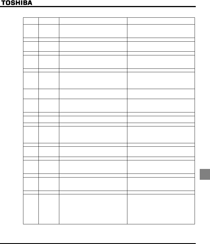
E6581381
K-17
11
■Table of output terminal functions 1
Function
No.
Code Function Action
0 LL Frequency lower limit ON: The output frequency is above the NN set
value.
OFF: The output frequency is equal to or less than
the NN set value.
1 LLN Inversion of frequency lower limit Inversion of LL setting
2 UL Frequency upper limit ON: Output frequency is equal to or higher than
WN value.
OFF: Output frequency is lower than WN value.
3 ULN Inversion of frequency upper limit Inversion of UL setting
4 LOW Low-speed detection signal ON: Output frequency is equal to or higher than
H value.
OFF: Output frequency is lower than H
value.
5 LOWN Inversion of low-speed detection signal Inversion of LOW setting
6 RCH Designated frequency attainment signal
(completion of acceleration/deceleration)
ON: The output frequency is equal to or less than
the specified frequency ± frequency set with
H.
OFF: The output frequency is above the specified
frequency ± frequency set with H.
7 RCHN Inversion of designated frequency attainment
signal (inversion of completion of
acceleration/deceleration)
Inversion of RCH setting
8 RCHF Set frequency attainment signal ON: The output frequency is equal to or less than
the frequency set with H ± H.
OFF: The output frequency is above the frequency
set with H ± H.
9 RCHFN Inversion of set frequency attainment signal Inversion of RCHF setting
10 FL Failure signal (trip output) ON: When inverter is tripped
OFF: When inverter is not tripped
11 FLN Inversion of failure signal (inversion of trip output) Inversion of FL setting
12 OT Over-torque detection ON: Torque current is equal to or larger than
H set value and longer than H
set time.
OFF: The torque current is equal to or less than
(H set value - H set value).
13 OTN Inversion of over-torque detection Inversion of OT
14 RUN Start/Stop ON: When operation frequency is output or during
(FD)
OFF: Operation stopped
15 RUNN Inversion of RUN/STOP Inversion of RUN setting
16 POL OL pre-alarm ON: 50% or more of calculated value of overload
protection level
OFF: Less than 50% of calculated value of
overload protection level
17 POLN Inversion of OL pre-alarm Inversion of POL setting
20 POT Over-torque detection pre-alarm ON: Torque current is equal to or larger than 70%
of H set value.
OFF: The torque current is below (H set
value x 70% - H set value).
21 POTN Inversion of over-torque detection pre-alarm Inversion of POT setting
22 PAL Pre-alarm One of the following is turned on:
ON POL, POT, MOFF, UC, OT, LL stop, COT,
and instantaneous power failure coast stop.
or E,R,J issues an alarm
All the following are turned off:
OFF POL, POT, MOFF, UC, OT, LL stop,
COT, and instantaneous power failure coast
stop.
or E,R,J issues no alarm
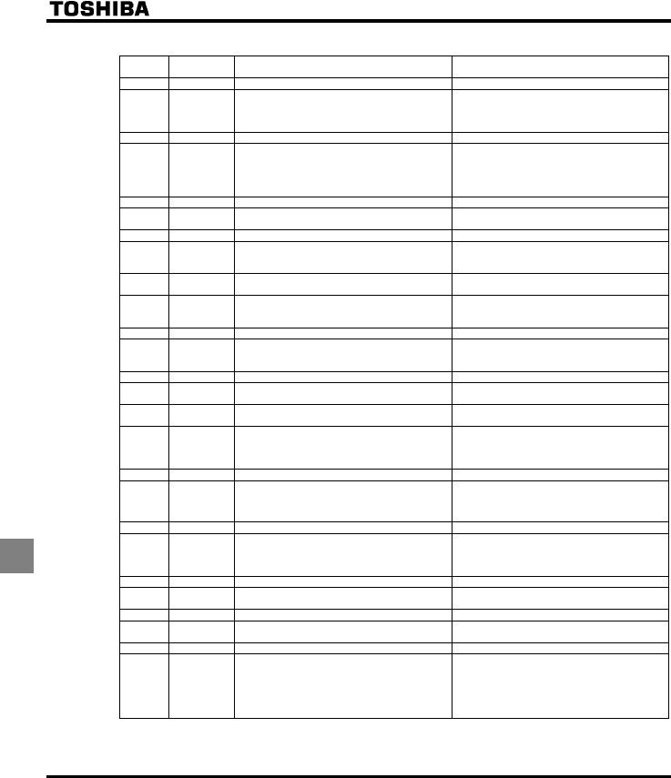
E6581381
K-18
11
■Table of output terminal functions 2
Function
No. Code Function Action
23 PALN Inversion of pre-alarm Inversion of PAL setting
24 UC Small-current detection ON: The output current is equal to or less than
H set value for H set time.
OFF: The output current is equal to or larger than
H set value + 10%.
25 UCN Inversion of small-current detection Inversion of UC setting
26 HFL Significant failure ON: QEC,QEN,QV,G,
GGR,GVP,GRJQ,GTT-
,QJ,WR,GH,WE,
GV[R,GRJ)
OFF: Failure other than the above
27 HFLN Inversion of significant failure Inversion of HFL setting
28 LFL Insignificant failure ON: (QE-,QR-,QJ,QN-)
OFF: Failure other than the above
29 LFLN Inversion of insignificant failure Inversion of LFL setting
30 RDY1 Ready for operation (including ST/RUN) ON: Ready for operation (ST and RUN are also
ON)
OFF: Others
31 RDY1N Inversion of ready for operation (including
ST/RUN)
Inversion of RDY1 setting
32 RDY2 Ready for operation (excluding ST/RUN) ON: Ready for operation (ST and RUN are not
ON)
OFF: Others
33 RDY2N Inversion of ready for operation (excluding ST/RUN) Inversion of RDY2
34 FCVIB Frequency VIB selection ON: VIB selected as frequency command
OFF: Terminal other than VIB selected as
frequency command
35 FCVIBN Inversion of frequency VIB selection Inversion of FCVIB
36 FLR Fault signal (put out also at the time of a retry) ON: When inverter trips or retries
OFF: When inverter does not trip or retry
37 FLRN Inversion of failure signal (put out also at the time
of a retry)
Inversion of FLR
38 OUT0 Specified data output 1 ON: Specified data from remote control FA50:
BIT0= 1
OFF: Specified data from remote control FA50:
BIT0= 0
39 OUT0N Inversion of specified data output 1 Inversion of OUT0 setting
42 COT Cumulative operation time alarm ON: Cumulative operation time is equal to or
longer than H
OFF: Cumulative operation time is shorter than
H
43 COTN Inversion of cumulative operation time alarm Inversion of COT
44 LTA Parts replacement alarm ON: Calculation for parts replacement time is
equal to or longer than the preset time
ON: Calculation for parts replancement time is
shorter than the preset time
45 LTAN Inversion of replacement alarm Inversion of LTA
48 LI1 F terminal input signal ON: The signal input to F terminal is ON
OFF: The signal input to F terminal is OFF
49 LI1N Inversion of F terminal input signal Inversion of LI1
50 LI2 R terminal input signal ON: The signal input to R terminal is ON
OFF: The signal input to R terminal is OFF
51 LI2N Inversion of R terminal input signal Inversion of LI2
52 PIDF Signal in accordance of frequency command (VIA) ON: Frequency commanded by HOQF or
H and that by VIA show the same
value.
OFF: Frequency commanded by HOQF or
H and that by VIA show different
values.
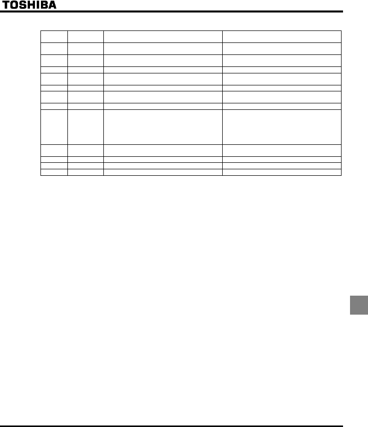
E6581381
K-19
11
■Table of output terminal functions 3
Function
No. Code Function Action
53 PIDFN Inversion of signal in accordance of frequency
command (VIA)
Inversion of PIDF setting
54 MOFF Undervoltage detection ON: Undervoltage detected
OFF: Other than undervoltage
55 MOFFN Inversion of undervoltage detection Inversion of MOFF
56 LOC Local/remote switching ON: Local mode
OFF: Remote mode
57 LOCN Inversion of local/remote switching Inversion of LOC
58 PTC PTC thermal alarm ON: 60% and over the protection level by PTC
OFF: Normal condition
59 PTCN Inversion of PTC thermal alarm Inversion of PTC
60 PIDFB Signal in accordance of frequency command (VIB) ON: Frequency commanded by HOQF or
H and that by VIB show the same
value.
OFF: Frequency commanded by HOQF or
H and that by VIB show different
values.
61 PIDFBN Inversion of signal in accordance of frequency
command (VIB)
Inversion of PIDFB setting
62-253 Disabled Invalid settings, always OFF (ignored) Invalid settings, always OFF (ignored)
254 AOFF Always OFF Always OFF
255 AON Always ON Always ON
E6581381
K-20
11
■Order of precedence of combined functions
XX: Impossible combination, X: Invalid, + : Valid under some conditions, O: Valid, @: Priority
Function No. / Function 123
5/
58
6/91011131415464841
/42
43 49 38 39 40 52/
53
1Standby @@@@OO@OOOOOO@OOOX
2Forward run command + X O O O X X O O X O O O X O O O X
3Reverse run command + + OOOX XOOXOOOXOOOX
5/58 Acceleration/deceleratio
n 2 selection + OO OOX XOOXOOOOOOXO
6~9 Preset-speed run
commands 1 to 3 + O O O O X X O O X O O O O O O O X
10 Reset command OOOOO XOOOXOOOOOOOX
11 Trip stop command from
external in
p
ut device + @ @ @ @ @ @ @ O + O @ O @ O O O X
13 DC braking command + @ @ @ @ O X @ O X O @ O @ O O O X
14 PID control prohibited OOOOOOX X O XOOOOOOO X
15 Permission of
p
arameter editin
g
OOOOOOOOO OOOOOOOOO
46 Thermal trip stop
command from external @@@@@@ + @@ O O O O @ O O O X
48 Remote/local control
forced switchin
g
OOOOOOOOOOO OOOOOOX
41/4
2
Frequency UP/DOWN
si
g
nal in
p
ut from OOOOOOOOOOOO OOOOOX
43 Clearing of UP/DOWN
fre
q
uenc
y
with external OOOOOOOOOOOOO OOOOX
49 Operation holding
(
cancellation of 3-wire +@@OOO X XOOXOOO OOOX
38 Frequency commands
forced switchin
g
OOOOOOOOOOOOOOO OOX
39 No.2 Switching of V/F
settin
g
OOOOOOOOOOOOOOOO XO
40 No.2 motor switching O O O @ O O O O O O O O O O O O @ O
52/
53
Forced operation
Fire-s
p
eed control @ @ @ O @ @ @ @ @ O @ @ @ @ @ @ O O
* For the functions of combined terminals (combined functions), refer to the table of their respective functions.
E6581381
L-1
12
12. Specifications
12.1 Models and their standard specifications
■Standard specifications
Item Specification
Input voltage 3-phase 200V
Applicable motor (kW) 0.4 0.75 1.5 2.2 4.0 5.5 7.5 11 15 18.5 22 30
Type VFFS1
Form 2004PM 2007PM 2015PM 2022PM 2037PM 2055PM 2075PM 2110PM 2150PM 2185PM 2220PM 2300PM
Capacity (kVA) Note 1) 1.1 1.8 2.9 4.0 6.7 9.2 12.2 17.6 23.2 28.5 33.5 44.6
Rated output/current
(A) Note 2) 2.8 4.6 7.5 10.6 17.5 24.2 32 46.2 61 74.8
(67.3)
88.0
(79.2)
117.0
(105.3)
Output voltage Note 3) 3-phase 200V to 240V
Rating
Overload current rating 110%-60 seconds, 180%-2 second
Voltage-current 3-phase 200V to 240V - 50/60Hz
Power
supply
Allowable fluctuation Voltage + 10%, -15% Note 4), frequency ±5%
Protective method IP20 Enclosed type (JEM1030)
IP00 Enclosed
type
(JEM1030)
Note 5)
Cooling method Forced air-cooled
Color Munsel 5Y-8/0.5
Built-in filter Basic filter
Item Specification
Input voltage 3-phase 400V
Applicable motor (kW) 0.4 0.75 1.5 2.2 4.0 5.5 7.5 11 15 18.5 22 30
Type VFFS1
Form 4004PL 4007PL 4015PL 4022PL 4037PL 4055PL 4075PL 4110PL 4150PL 4185PL 4220PL 4300PL
Capacity (kVA) Note 1) 1.1 1.6 2.8 3.9 6.9 9.1 12.2 17.1 23.2 28.2 33.2 44.6
Rated output current
(A) Note 2) 1.4 2.2 3.7 5.1 9.1 12.0 16.0 22.5 30.5 37.0
(33.3)
43.5
(39.2)
58.5
(52.7)
Rated output voltage
Note 3) 3-phase 380V to 480V
Rating
Overload current rating 110%-60 seconds, 180% -2 second
Voltage-current 3-phase 380V to 480V - 50/60Hz
Power
supply
Allowable fluctuation Voltage + 10%, -15% Note 4), frequency ±5%
Protective method, IP20 Enclosed type (JEM1030)
IP00 Enclosed
type (JEM1030)
Note 5)
Cooling method Forced air-cooled
Color Munsel 5Y-8/0.5
Built-in filter EMI filter
Note 1: Capacity is calculated at 220V for the 200V models, at 440V for the 400V models.
Note 2: The rated output current in the parenthesis is at 12kHz of PWM carrier frequency (H) setting.
Note 3: Maximum output voltage is the same as the input voltage.
Note 4: ±10% when the inverter is used continuously (load of 100%).
Note 5: Inverter, 22kW or greater, do not have wiring port covers, they have large openings, but there is no space to bend the
external cables inside the unit. If they are fitted external to the cabinet, please use an optional wiring port cover.

E6581381
L-2
12
■Common specification
Item Specification
Control system Sinusoidal PWM control
Rated output voltage Adjustable within the range of 50 to 660V by correcting the supply voltage (not adjustable above the input
voltage)
Output frequency range 0.5 to 200.0Hz, default setting: 0.5 to 80Hz, maximum frequency: 30 to 200Hz
Minimum setting steps
of frequency
0.1Hz: analog input (when the max. frequency is 100Hz), 0.01Hz: Operation panel setting and
communication setting.
Frequency accuracy Digital setting: within ±0.01% of the max. frequency (-10 to +60°C)
Analog setting: within ±0.5% of the max. frequency (25°C ±10°C)
Voltage/frequency
characteristics
V/F constant, variable torque, automatic torque boost, vector control, automatic energy-saving, PM motor
control. Auto-tuning. Base frequency (25 - 200Hz) adjusting to 1 or 2, torque boost (0 - 30%) adjusting to
1 or 2, adjusting frequency at start (0.5 - 10Hz)
Frequency setting
signal
External frequency potentiometer (connectable to a potentiometer with a rated impedance of 1 - 10kΩ), 0
- 10Vdc (input impedance: VIA/VIB=30kΩ, 4 - 20mAdc (Input impedance: 250Ω).
Terminal board base
frequency
The characteristic can be set arbitrarily by two-point setting. Possible to set individually for three
functions: analog input (VIA and VIB) and communication command.
Frequency jump Three frequencies can be set. Setting of the jump frequency and the range.
Upper- and lower-limit
frequencies
Upper-limit frequency: 0 to max. frequency, lower-limit frequency: 0 to upper-limit frequency
PWM carrier frequency Adjustable within a range of 6.0 to 16.0Hz (default: 8 or 12kHz).
Principal control functions
PID control Setting of proportional gain, integral gain, differential gain and control wait time. Checking whether the
amount of processing amount and the amount of feedback agree.
Acceleration/decelerati
on time
Selectable from among acceleration/deceleration times 1 and 2 (0.0 to 3200 sec.). Automatic
acceleration/deceleration function. S-pattern acceleration/deceleration 1 and 2 and S-pattern adjustable.
Control of forced rapid deceleration and dynamic rapid deceleration
DC braking Braking start-up frequency: 0 to maximum frequency, braking rate: 0 to 100%, braking time: 0 to 20
seconds, emergency DC braking
Input terminal function
(programmable)
Possible to select from among 57 functions, such as forward/reverse run signal input, operation base
signal input and reset signal input, to assign to 4 input terminals. Logic selectable between sink and
source.
Output terminal
functions
(programmable)
Possible to select from among 58 functions, such as upper/lower limit frequency signal output, low speed
detection signal output, specified speed reach signal output and failure signal output, to assign to FL
relay output, RY output terminals.
Forward/reverse run The RUN and STOP keys on the operation panel are used to start and stop operation, respectively. The
switching between forward run and reverse run can be done from one of the three control units: operation
panel, terminal board and external control unit.
Preset speed operation Base frequency + 7-speed operation possible by changing the combination of 3 contacts on the terminal
board.
Retry operation Capable of restarting automatically after a check of the main circuit elements in case the protective
function is activated. 10 times (Max.) (selectable with a parameter)
Various prohibition
settings
Possible to write-protect parameters and to prohibit the change of panel frequency settings and the use
of operation panel for operation, emergency stop or resetting.
Auto-restart operation In the event of a momentary power failure, the inverter reads the rotational speed of the coasting motor
and outputs a frequency appropriate to the rotational speed in order to restart the motor smoothly. This
function can also be used when switching to commercial power.
Drooping function The motor is allowed to “slip” according to the load torque current.
Operation specifications
Failure detection signal 1c-contact output: (250Vac-0.5A-cosФ=0.4)
<Continued overleaf>
E6581381
L-3
12
<Continued>
Item Specification
Protective function Stall prevention, current limitation, over-current, output short circuit, over-voltage, over-voltage limitation,
undervoltage, ground fault, power supply phase failure, output phase failure, overload protection by
electronic thermal function, armature over-current at start-up, load side over-current at start-up, over-
torque, undercurrent, overheating, cumulative operation time, life alarm, emergency stop, various pre-
alarms
Electronic thermal
characteristic
Switching between standard motor and constant-torque VF motor, switching between motors 1 and 2,
setting of overload trip time, adjustment of stall prevention levels 1 and 2, selection of overload stall
Protective function
Reset function Function of resetting by closing contact 1a or by turning off power or the operation panel. This function is
also used to save and clear trip records.
Alarms Stall prevention, overvoltage, overload, under-voltage, setting error, retry in process, upper/lower limits
Causes of failures Over-current, overvoltage, overheating, short-circuit in load, ground fault, overload on inverter, over-
current through arm at start-up, over-current through load at start-up, CPU fault, EEPROM fault, RAM
fault, ROM fault, communication error. (Selectable: Emergency stop, under-voltage, low voltage, over-
torque, motor overload, output open-phase)
Monitoring function Operation frequency, operation frequency command, forward/reverse run, output current, voltage in DC
section, output voltage, torque, torque current, load factor of inverter, input power, output power,
information on input terminals, information on output terminals, version of CPU1, version of CPU2,
version of memory, PID feedback amount, frequency command (after PID), integral input power, integral
output power, rated current, output speed, communication counter, normal state communication counter,
causes of past trips 1 through 4, parts replacement alarm, cumulative operation time
Past trip monitoring
function
Stores data on the past four trips: number of trips that occurred in succession, operation frequency,
direction of rotation, load current, input voltage, output voltage, information on input terminals, information
on output terminals, and cumulative operation time when each trip occurred.
Output for frequency
meter
Analog output: (1mAdc full-scale DC ammeter or 7.5Vdc full-scale DC ammeter / Rectifier-type AC
voltmeter, 225% current Max. 1mAdc, 7.5Vdc full-scale), 4 to 20mA/0 to 20mA output
4-digit 7-segments LED Frequency: inverter output frequency.
Alarm: stall alarm “C”, overvoltage alarm “P”, overload alarm “L”, overheat alarm “H”.
Status: inverter status (frequency, cause of activation of protective function, input/output voltage,
output current, etc.) and parameter settings.
Free-unit display: arbitrary unit (e.g. rotating speed) corresponding to output frequency.
Display function
Indicator Lamps indicating the inverter status by lighting, such as RUN lamp, MON lamp, PRG lamp, % lamp, Hz
lamp, LOC/REM key lamp, UP/DOWN key lamp and RUN key lamp. The charge lamp indicates that the
main circuit capacitors are electrically charged.
Use environments Indoor, altitude: 1000m (Max.), not exposed to direct sunlight, corrosive gas, explosive gas or vibration
(less than 5.9m/s2) (10 to 55Hz)
Ambient temperature -10 to +60°C Note1) Note2)
Storage temperature -20 to +65°C
Environments
Relative humidity 20 to 93% (free from condensation and vapor).
Note 1: Above 40°C: Remove the seal from the top of the inverter and use the inverter with the rated output current reduced.
Note 2: If inverters are installed side by side (with no sufficient space left between them): Remove the seal from the top of
each inverter.
When installing the inverter where the ambient temperature will rise above 40°C, remove the seal from the top of the
inverter and use the inverter with the rated output current reduced.
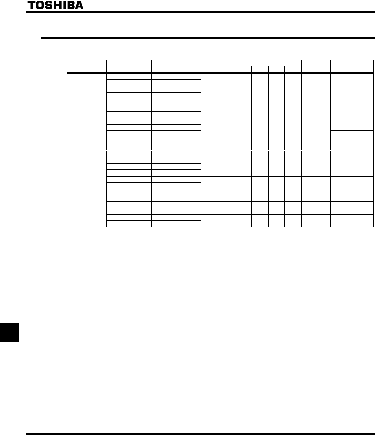
E6581381
L-4
12
12.2 Outside dimensions and mass
■Outside dimensions and mass
Dimensions (mm)
Voltage class Applicable motor
(kW) Inverter type WHDW1H1H2
Drawing Approx. weight
(kg)
0.4 VFFS1-2004PM
0.75 VFFS1-2007PM
1.5 VFFS1-2015PM
2.2 VFFS1-2022PM
105 130 150 93 121.5 13 A1.2
4.0 VFFS1-2037PM 140 170 150 126 157 14 B 2.1
5.5 VFFS1-2055PM
7.5 VFFS1-2075PM 180 220 170 160 210 12 C 4.3
11 VFFS1-2110PM
15 VFFS1-2150PM 8.6
18.5 VFFS1-2185PM
245 310 190 225 295 19.5 D
8.9
22 VFFS1-2220PM 240 420 214 206 403 - E 16.4
3-phase 200V
30 VFFS1-2300PM 320 630 290 280 605 - F 38.0
0.4 VFFS1-4004PL
0.75 VFFS1-4007PL
1.5 VFFS1-4015PL
2.2 VFFS1-4022PL
105 130 150 93 121.5 13 A 1.4
4.0 VFFS1-4037PL
5.5 VFFS1-4055PL 140 170 150 126 157 14 B 2.4
7.5 VFFS1-4075PL
11 VFFS1-4110PL 180 220 170 160 210 12 C 4.7
15 VFFS1-4150PL
18.5 VFFS1-4185 PL 245 310 190 225 295 19.5 D9.0
22 VFFS1-4220 PL
3-phase 400V
30 VFFS1-4300 PL 240 420 214 206 403 - E 15.4
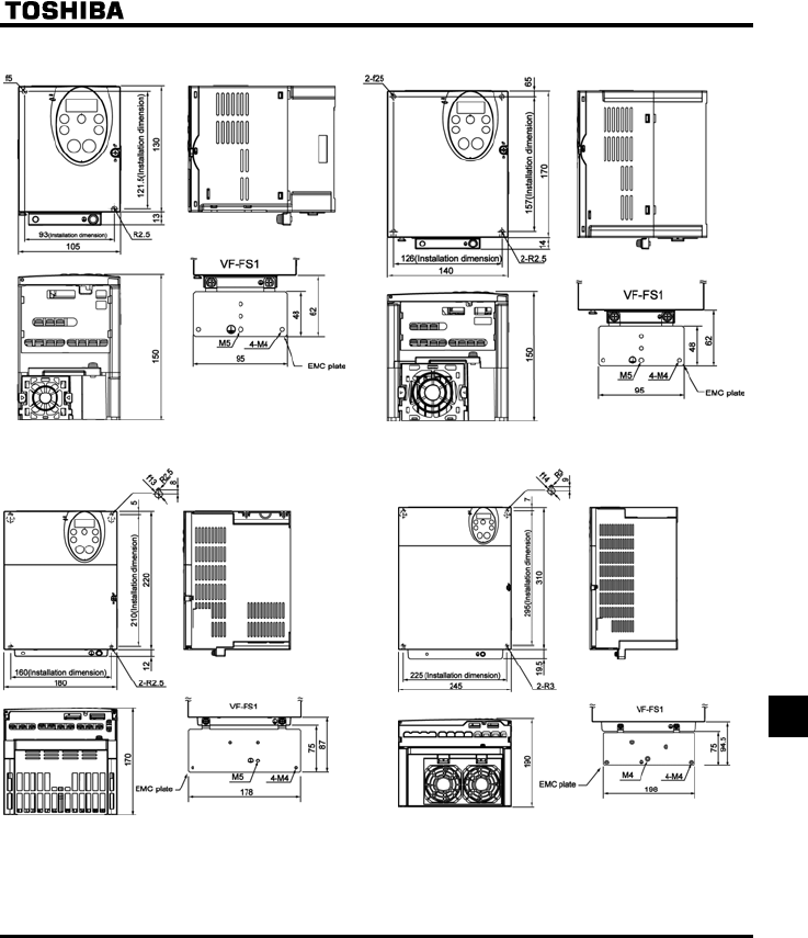
E6581381
L-5
12
■Outline drawing
Fig.A Fig.B
Fig.C Fig.D
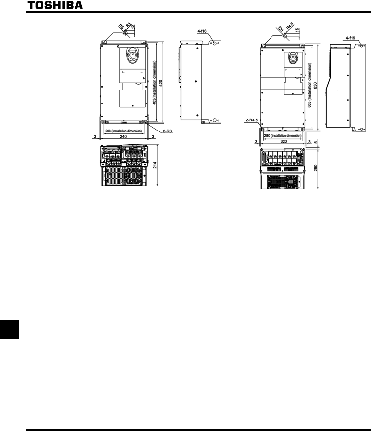
E6581381
L-6
12
Fig.E Fig.F
Note 1: To make it easier to grasp the dimensions of each inverter, dimensions common to all inverters in these
figures are shown with numeric values but not with symbols.
Here are the meanings of the symbols used.
W: Width
H: Height
D: Depth
W1: Mounting dimension (horizontal)
H1: Mounting dimension (vertical)
H2: Height of EMC plate mounting area
Note 2: Here are the avaiable EMC plate
Fig.A, Fig.B : EMP004Z (Approx. weight : 0.1kg)
Fig.C : EMP005Z (Approx. weight : 0.3kg)
Fig.D : EMP006Z (Approx. weight : 0.3kg)
Note 3: The models shown in Fig. A is sfixed at two points: in the upper left and lower right corners.

E6581381
M-1
13
13. Before making a service call
- Trip information and remedies
13.1 Trip causes/warnings and remedies
When a problem arises, diagnose it in accordance with the following table.
If it is found that replacement of parts is required or the problem cannot be solved by any remedy described in the
table, contact your Toshiba dealer.
[Trip information]
Error code Failure code Problem Possible causes Remedies
QE
QER
0001
0025
Overcurrent during
acceleration
Overcurrent flowing
in element during
acceleration
•The acceleration time CEE is too short.
•The V/F setting is improper.
•A restart signal is imput to the rotating
motor after a momentary stop, etc.
•A special motor (e.g. motor with a small
impedance) is used.
•There is possibility of Ground fault trip.
•Increase the acceleration time CEE.
•Check the V/F parameter.
•Use H (auto-restart) and H
(coast stop).
•Adjust the carrier frequency H.
•Set the carrier frequency control mode
selection parameter H to 1 or 3
(carrier frequency decreased
automatically).
QE
QER
0002
0026
Overcurrent during
deceleration
Overcurrent flowing
in element during
decelearion
•The deceleration time FGE is too short.
•There is possibility of Ground fault trip.
•Increase the deceleration time FGE.
•Set the carrier frequency control mode
selection parameter H to 1 or 3
(carrier frequency decreased
automatically).
QE
QER
0003
0027
Overcurrent during
constant speed
operation
Overcurrent flowing
in element during
operation
•The load fluctuates abruptly.
•The load is in an abnormal condition.
•There is possibility of Ground fault trip.
•Reduce the load fluctuation.
•Check the load (operated machine).
•Set the carrier frequency control mode
selection parameter H to 1 or 3
(carrier frequency decreased
automatically).
ER
ER
ER
0025
0026
0027
Ground fault trip
Arm overcurrent at
start-up
(for 11 and 15 kW
models only)
•A current leaked from an output cable or
the motor to ground.
•A main circuit elements is defective.
•Check cables, connectors, and so on for
ground faults.
•Make a service call.
QEN 0004 Overcurrent (An
overcurrent on the
load side at start-up)
•The insulation of the output main circuit or
motor is defective.
•The motor has too small impedance.
•A 11 or 15 kW model was started,
although a current is leaked from an
output cable or the motor to ground.
•Check the cables and wires for defective
insulation.
•When using a 11 or 15 kW model, check
cables, connectors, and so on for ground
faults.
QEC 0005 Arm overcurrent at
start-up
•A main circuit elements is defective.
•There is possibility of Ground fault trip.
•Make a service call.
*
GRJ
0008 Input phase failure •A phase failure occured in the input line of
the main circuit.
•Check the main circuit input line for phase
failure.
•Enable H (input phase failure
detection).
•Check the capacitor in the main circuit for
exhaustion.
*
GRJQ
0009 Output phase failure •A phase failure occurred in the output line
of the main circuit.
•Check the main circuit output line, motor,
etc. for phase failure.
•Enable H (Output phase failure
detection).
* You can select a trip ON/OFF by parameters.
(Continued overleaf)

E6581381
M-2
13
(Continued)
Error code Failure code Problem Possible causes Remedies
QR 000A Overvoltage during
acceleration
•The imput voltage fluctuates abnormally.
(1) The power supply has a capacity of
200kVA or more.
(2) A power factor improvement capacitor is
opened or closed.
(3) A system using a thyrister is connected
to the same power distribution line.
•A restart signal is input to the rotating
motor after a momentary stop, etc.
•There is possibility of output phase
failure.
•Insert a suitable input reactor.
•Use H (auto-restart) and H
(coast stop).
•Check the main circuit output line, motor,
etc. for phase failure.
QR 000B Overvoltage during
deceleration
•The deceleration time FGE is too short.
(Regenerative energy is too large.)
•H (overvoltage limit operation) is
off.
•The input voltage fluctuates abnormally.
(1) The power supply has a capacity of
200kVA or more.
(2) A power factor improvement capacitor is
opened and closed.
(3) A system using a thyrister is connected
to the same power distribution line.
•There is possibility of output phase
failure.
•Increase the deceleration time FGE.
•Enable H (overvoltage limit
operation).
•Insert a suitable input reactor.
•Check the main circuit output line, motor,
etc. for phase failure.
QR 000C Overvoltage during
constant-speed
operation
•The input voltage fluctuates abnormally.
(1) The power supply has a capacity of
200kVA or more.
(2) A power factor improvement capacitor is
opened or closed.
(3) A system using a thyrister is connected
to the same power distribution line.
•The motor is in a regenerative state
because the load causes the motor to run
at a frequency higher than the inverter
output frequency.
•There is possibility of output phase
failure.
•Insert a suitable input reactor.
•Check the main circuit output line, motor,
etc. for phase failure.
QN 000D Inverter overload •The acceleration time ACC is too short.
•The DC braking amout is too large.
•The V/F setting is improper.
•A restart signal is input to the rotating
motor after a momentary stop, etc.
•The load is too large.
•Increase the acceleration time CEE.
•Reduce the DC braking amount H
and the DC braking time H.
•Check the V/F parameter setting.
•Use H (auto-restart) and H
(coast stop).
•Use an inverter with a larger rating.
QN 000E Motor overload •The V/F setting is improper.
•The motor is locked up.
•Low-speed operation is performed
continuously.
•An excessive load is applied to the motor
during operation.
•Check the V/F parameter setting.
•Check the load (operated machine).
•Adjust QNO to the overload that the
motor can withstand during operation in a
low speed range.
*
QV
0020 Over-torque trip •Over-torque reaches to a detection level
during operation.
•Enable H (over-torque trip
selection).
•Check system error.
QJ 0010 Overheat •The cooling fan does not rotate.
•The ambient temperature is too high.
•The vent is blocked up.
•A heat generating device is installed close
to the inverter.
•The thermistor in the unit is broken.
•Restart the operation by resetting the
inverter after it has cooled down enough.
•The fan requires replacement if it does
not rotate during operation.
•
Secure sufficient space around the inverter.
•Do not place any heat generating device
near the inverter.
•Make a service call.
* You can select a trip ON/OFF by parameters.
(Continued overleaf)

E6581381
M-3
13
(Continued)
Error code Failure code Problem Possible causes Remedies
QJ 002E External thermal trip •An external thermal trip is input.
•PTC protection worked.
•Check the external thermal input.
•Check the PTC in the motor.
G0011 Emergency stop •During automatic operation or remote
operation, a stop command is entered
from the operation panel or a remote
input device.
•Reset the inverter.
GGR 0012 EEPROM fault 1 •A data writing error occurs. •Turn off the inverter, then turn it again. If it
does not recover from the error, make a
service call.
GGR 0013 EEPROM fault 2 •Power supply is cut off during V[R
operation and data writing is aborted.
•Turn the power off temporarily and turn it
back on, and then try V[R operation
again.
GGR 0014 EEPROM fault 3 •A data reading error occurred. •Turn off the inverter, then turn it again. If it
does not recover from the error, make a
service call.
GTT 0015 Main unit RAM fault •The control RAM is defective. •Make a service call.
GTT 0016 Main unit ROM fault •The control ROM is defective. •Make a service call.
GTT 0017 CPU fault 1 •The control CPU is defective. •Make a service call.
*
GTT
0018 Communication error •An error arises during serial
communication.
•Check the remote control device, cables,
etc.
GTT 001A Current detector fault •The current detector is defective. •Make a service call.
GTT 001B Network error •The error was occurred during Network
communication.
•Check the Network device and wiring.
*
WE
001D Low-current
operation
Trip
•The output current decreased to a low-
current detection level during operation.
•Enable H (low-current detection).
•Check the suitable detection level for the
system (H, H).
•Make a service call if the setting is
correct.
*
WR
001E Undervoltage trip
(main circuit)
•The input voltage (in the main circuit) is
too low.
•Check the input voltage.
•Enable H (undervoltage trip
selection).
•To cope with a momentary stop due to
undervoltage, enable H (coast stop)
and H (auto-restart).
GH 0022 Ground fault trip •A ground fault occurs in the output cable
or the motor.
•Check the cable and the motor for ground
faults.
GVP 0054 Auto-tuning error •Check the motor parameter H to H.
•The motor with the capacity of 2 classes or less than the inverter is used.
•The output cable is too thin.
•The motor is rotating.
•The inverter is used for loads other than those of three-phase induction motors.
GV[R 0029 Inverter
type error
•Circuit board is changed.
(Or main circuit/drive circuit board)
•Make a service call.
*
G
0032 Brea in analog signal
cable
•The signal input via VIA is below the
analog sinal detectio level set with
H.
•Check the cables for breaks. And check
the setting of input signal or setting value
of H.
G 0033 CPU
communications
error
•A communications error occurs between
control CPUs.
•Make a service call.
G 0034 Excessive torque
boosted
•The torque boost parameter H is
set too high.
•The motor has too small impedance.
•Re do the Auto-tuning then set H.
•Decrease the setting of the torque boost
parameter H.
G 0035 CPU fault 2 •The control CPU is defective. •Make a service call.
UQWV 002F Step-out
(For PM motor only)
•The motor shaft is locked.
•One output phase is open.
•An impact load is applied.
•Unlock the motor shaft.
•Check the interconnect cables between
the inverter and the motor.
* You can select a trip ON/OFF by parameters.

E6581381
M-4
13
[Alarm information] Each message in the table is displayed to give a warning but does not cause the inverter to
trip.
Error code Problem Possible causes Remedies
QHH ST terminal OFF •The ST-CC circuit is opened. •Close the ST-CC circuit.
OQHH Undervoltage in main
circuit
•The supply voltage between R, S and T is
under voltage.
•Measure the main circuit supply voltage.
If the voltage is at a normal level, the
inverter requires repairing.
TVT[ Retry in process •The inverter is n the process of retry.
•A momentary stop occurred.
•The inverter is normal if it restarts after
several tens of senconds.
The inverter restarts automatically. Be
careful of the machine because it may
suddenly restart.
GTT Frequency point
setting error alarm
•The frequency setting signals at points 1
and 2 are set too close to each other.
•Set the frequency setting signals at points
1 and 2 apart from each other.
ENT Clear command
acceptable
•This message is displayed when pressing
the STOP key while an error code is
displayed.
•Press the STOP key again to clear the
trip.
GQHH Emergency stop
command
acceptable
•The operation panel is used to stop the
operation in automatic control or remote
control mode.
•Press the STOP key for an emergency
stop.
To cancel the emergency stop, press any
other key.
J/
NQ
Setting error alarm /
An error code and
data are displayed
alternately twice
each.
•An error is found in a setting when data is
reading or writing.
•Check whether the setting is made
correctly.
JGCF/
GPF
Display of first/last
data items
•The first and last data item in the CWJ
data group is displayed.
•Press MODE key to exit the data group.
FD DC braking •DC braking in process •The message goes off in several tens of
seconds if no problem occurs. Note)
FDZP Shaft fixing control •Motor shaft fixing control is in process. •Normal if the message disappears when
a stop command is entered (or the
operation command is canceled).
G Flowing out of
excess number of
digits
•The number of digits such as frequencies
is more than 4.
(The upper digits have a priority.)
•Lower the fequency free unit
magnification H.
UVQR Instantaneous power
failure coast stop
function activated.
•The coast stop function set with H
(Instantaneous power failure coast stop)
is activated.
•To restart operation, reset the inverter or
input an operation signal again.
NUVR Auto-stop because of
continuous operation
at the lower-limit
frequency
•The automatic stop function selected with
H was activated.
•To deactivate the automatic stop function,
increase the frequency command above
the lower-limit frequency (LL) + 0.2 Hz or
turn off the operation command.
KPKV Parameters in the
process of
initialization
•Parameters are being initialized to default
values.
•Normal if the message disappears after a
while (several seconds to several tens of
seconds).
G Operation panel key
fault
•The RUN or STOP key is held down for
more than 20 seconds.
•The RUN or STOP key is faulty.
•Check the operation panel.
CVP Auto-tuning •Auto-tuning in process •Normal if it the message disappears after
a few seconds.
M Integral input power •Integral input power is more than
999.99kWh.
•Press and hold down the ENT key for 3
seconds or more when power is off or
when the input terminal function CKWH
is turned on or displayed.
J Integral output power •Integral output power is more than
999.99kWh.
•Press and hold down the ENT key for 3
seconds or more when power is off or
when the input terminal function CKWH
is turned on or displayed.
Note: When the ON/OFF function is selected for DC braking (DB), using the input terminal selection parameter,
you can judge the inverter to be normal if “FD” disappears when opening the circuit between the terminal and
CC.

E6581381
M-5
13
[Prealarm display]
EOvercurrent alarm Same as QE (overcurrent)
ROvervoltage alarm Same as QR (overvoltage)
NOverload alarm Same as QN and QN (overload)
JOverheat alarm Same as QJ (overheat)
If two or more problems arise simultaneously, one of the following alarms appears and blinks.
ER, RN, ERN
The blinking alarms E, R, N, J are displayed in this order from left to right.
13.2 Restoring the inverter from a trip
Do not reset the inverter when tripped because of a failure or error before eliminating the cause. Resetting the
tripped inverter before eliminating the problem causes it to trip again.
The inverter can be restored from a trip by any of the following operations:
(1) By turning off the power (Keep the inverter off until the LED turns off.)
Note: ⇒ See section 6.17.3 (inverter trip retention selection H) for details.
(2) By means of an external signal (Short circuit between RES and CC on terminal board → Open)
(3) By operation panel operation
(4) By inputting a trip clear signal from a remote input device
(Refer to the remote input device operating manual for details.)
To reset the inverter by operation panel operation, follow these steps.
1. Press the key and make sure that ENT is displayed.
2. Pressing the key again will reset the inverter if the cause of the trip has already been eliminated.
+In case of a trip due to overheating (QJ), the inverter checks the temperature within. Wait until the
temperature in the inverter falls sufficiently before resetting the inverter.
[Caution]
Turning the inverter off then turning it on again resets the inverter immediately. You can use this mode of
resetting if there is a need to reset the inverter immediately. Note, however, that this operation may damage
the system or the motor if it is repeated frequently.
STOP
STOP
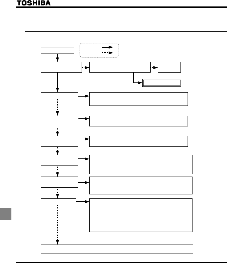
E6581381
M-6
13
13.3 If the motor does not run while no trip message is
displayed ...
If the motor does not run while no trip message is displayed, follow these steps to track down the cause.
The motor does not run.
Is the 7-segment LED
extinguished?
Check the power supply and the MCCB.
Is power being supplied normally?
Supply the power
normally.
Make a service call.
Is QHH displayed? •The ST-CC circuit is opened. Close the circuit between CC and the terminal to which
the ST (standby) function on the control circuit terminal is assigned.
•Check the setting of H (always active function selection). ⇒ See section 6.3.1.
Is any failure message
displayed?
⇒ See section 1.3.1.
Track down and eliminate the cause of the failure and then reset the inverter.
⇒ See section 13.2.
A
re TVT[ and a failure
message displayed alternately?
The inverter is in the process of retrying. The retry function can be disabled by normal
or emergency stop operation, or by turning off the inverter.
Q displayed?
Is the RUN key lamp lighted?
Is the RUN key lamp off?
•Check to see that the frequency setting signal is not set at zero.
•Check the settings of the frequency setting signal parameters HOQF, H, H.
⇒ See section 6.5.
•Check the frequency setting signal points 1 and 2 settings. ⇒ See section 6.5.
•Check that the start-up frequency is not higher than the operation frequency.
⇒ See section 6.6.
•Check that the frequency setting (preset-speed operation frequency, etc.) is not set at
zero.
•Check that the motor is not under a too large load or not locked up.
→Reduce the load if necessary.
Determine the cause, using the parameter display function and the status monitoring function.
⇒ See section 11 for the parameter display function or section 8 for the status motoring function.
•When operation panel operation is selected ... Press the RUN key to start the operation.
•Check whether the operation panel operation frequency is set properly.
⇒ See section 3.1.2
•When another control mode is selected ... Change the setting of the operation control
mode selection EOQF. ⇒ See section 5.3.
•When operation panel operation is selected ... Change the setting of the operation
control mode selection parameter EOQF to 1. ⇒ See section 5.3.
•You can check the setting of each input terminal on the monitor. ⇒ See section 8.1.
•When another control mode is selected ... Check whether the external operation
command is entered.
YES:
NO :

E6581381
M-7
13
13.4 How to determine the causes of other problems
The following table provides a listing of other problems, their possible causes and remedies.
Problems Causes and remedies
The motor runs in the
wrong direction.
•Invert the phases of the output terminals U, V and W.
•Invert the forward/reverse run-signal terminals of the external input device.
⇒ See section 6.3 "Assignment of functions to control terminals".
•Change the setting of the parameter HT in the case of panel operation.
The motor runs but its
speed does not change
normally.
•The load is too heavy. Reduce the load.
•
The soft stall function is activated. Disable the soft stall function. ⇒ See section 5.12.
•The maximum frequency HJ and the upper limit frequency WN are set too low.
Increase the maximum frequency HJ and the upper limit frequency WN.
•
The frequency setting signal is too low. Check the signal set value, circuit, cables, etc.
•Check the setting characteristics (point 1 and point 2 settings) of the frequency setting
signal parameters. ⇒ See section 6.5.
•If the motor runs at a low speed, check to see that the stall prevention function is
activated because the torque boost amount is too large.
Adjust the torque boost amount (XD) and the acceleration time (CEE).
⇒ See section 5.11 and 5.1.
The motor does not
ac-celerate or decelerate
smoothly.
•The acceleration time (CEE) or the deceleration time (FGE) is set too short.
Increase the acceleration time (CEE) or the deceleration time (FGE).
A too large current flows
into the motor.
•The load is too heavy. Reduce the load.
•If the motor runs at a low speed, check whether the torque boost amount is too large. ⇒
⇒ See section 5.11.
The motor runs at a higher
or lower speed than the
specified one.
•The motor has an improper voltage rating. Use a motor with a proper voltage rating.
•The motor terminal voltage is too low.
Check the setting of the base frequency voltage parameter (XNX) .
⇒ See section 6.12.5.
Replace the cable with a cable larger in diameter.
•
The reduction gear ratio, etc., are not set properly. Adjust the reduction gear ratio, etc.
•The output frequency is not set correctly. Check the output frequency range.
•Adjust the base frequency. ⇒ See section 5.9.
The motor speed fluctu-ates
during operation.
•The load is too heavy or too light. Reduce the load fluctuation.
•The inverter or motor used does not have a rating large enough to drive the load.
Use an inverter or motor with a rating large enough.
•Check whether the frequency setting signal changes.
•If the V/F control selection parameter RV is set at , check the vector control setting,
operation conditions, etc. ⇒ See section 5.10.
Parameter settings cannot
be changed.
Change the setting of the parameter H (prohibition of change of parameter
setting) to (permitted) if it is set at (prohibited).
* For reasons of safety, some parameters cannot be reprogrammed while the inverter is
running. ⇒ See section 4.2.6.
How to cope with parameter setting-related problems
If you forget parameters
which have been reset
•You can search for all reset parameters and change their settings.
⇒ See section 4.2.3 for details.
If you want to return all
reset parameters to their
respective default settings
•You can return all parameters which have been reset to their default settings.
⇒ See section 4.2.7 for details.
E6581381
N-1
14
14. Inspection and maintenance
Danger
Mandatory
•The equipment must be inspected every day.
If the equipment is not inspected and maintained, errors and malfunctions may not be discovered
which could lead to accidents.
•Before inspection, perform the following steps.
(1) Shut off all input power to the inverter.
(2) Wait at least ten minutes and check to make sure that the charge lamp is no longer lit.
(3) Use a tester that can measure DC voltages (800V DC or more), and check that the voltage to the
DC main circuits (across PA/+ and PC/-) does not exceed 45V.
Performing an inspection without carrying out these steps first could lead to electric shock.
Be sure to inspect the inverter regularly and periodically to prevent it from breaking down because of the environment
of use, such as temperature, humidity, dust and vibration, or deterioration of its components with aging.
14.1 Regular inspection
Since electronic parts are susceptible to heat, install the inverter in a cool, well-ventilated and dust-free place.
This is essential for increasing the service life.
The purpose of regular inspections is to maintain the correct environment of use and to find any sign of failure or
malfunction by comparing current operation data with past operation records.
Inspection procedure
Subject of
inspection Inspection item Inspection
cycle Inspection method Criteria for judgement
1)Dust, temperature
and gas
Occasionall
y
1)Visual check, check
by means of a
thermometer, smell
check
1) Improve the environment if
it is found to be
unfavorable.
2)Drop of water or
other liquid
Occasionall
y
2)Visual check 2) Check for any trace of
water condensation.
1. Indoor
environment
3
)
Room temperature Occasionall
y
3)Check by means of
a thermometer 3
)
Max. temperature: 60°C
2. Units and
components 1
)
Vibration and noise Occasionall
y
Tactile check of the
cabinet
Is something unusual is
found, open the door and
check the transformer,
reactors, contactors, relays,
cooling fan, etc., inside. If
necessary, stop the
operation.
1)Load current Occasionall
y
Moving-iron type AC
ammeter
2)Voltage (*) Occasionall
y
Rectifier type AC
voltmeter
3. Operation
data
(
output side
)
3) Temperature Occasionall
y
Thermometer
To be within the rated
current, voltage and
temperature.
No significant difference
from data collected in a
normal state.
*) The voltage measured may slightly vary from voltmeter to voltmeter. When measuring the voltage,
always take readings from the same circuit tester or voltmeter.
E6581381
N-2
14
■Check points
1. Something unusual in the installation environment
2. Something unusual in the cooling system
3. Unusual vibration or noise
4. Overheating or discoloration
5. Unusual odor
6. Unusual motor vibration, noise or overheating
7. Adhesion or accumulation of foreign substances (conductive substances)
■ Cautions about cleaning
To clean the inverter, wipe dirt off only its surface with a soft cloth but do not try to remove dirt or stains from
any other part. If stubborn stains persist, remove them by wiping gently with a cloth dampened with neutral
detergent or ethanol.
Never use any of the chemicals in the table below; the use of any of them may damage or peel the coating
away from molded parts (such as plastic covers and units) of the inverter.
Acetone Ethylene chloride Tetrachloroethane
Benzen Ethyl acetate Trichloroethylene
Chloroform Glycerin Xylene
14.2 Periodical inspection
Make a periodical inspection at intervals of 3 or 6 months depending on the operating conditions.
Danger
Mandatory
•Before inspection, perform the following steps.
(1) Shut off all input power to the inverter.
(2) Wait at least ten minutes and check to make sure that the charge lamp is no longer lit.
(3) Use a tester that can measure DC voltages (800V DC or more), and check that the voltage to the
DC main circuits (across PA/+ and PC/-) does not exceed 45V.
Performing an inspection without carrying out these steps first could lead to electric shock.
Prohibited
• Never replace any part.
This could be a cause of electric shock, fire and bodily injury. To replace parts, call the local sales
agency.
■Check items
1. Check to see if all screwed terminals are tightened firmly. If any screw is found loose, tighten it again
with a screwdriver.
2. Check to see if all caulked terminals are fixed properly. Check them visually to see that there is no trace
of overheating around any of them.
3. Check all cables and wires for damage. Check them visually.
4. Remove dirt and dust. With a vacuum cleaner, remove dirt and dust. When cleaning, clean the vents
and the printed circuit boards. Always keep them clean to prevent an accident due to dirt or dust.
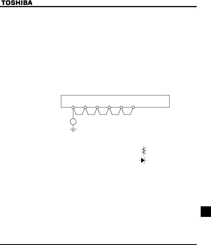
E6581381
N-3
14
5. If no power is supplied to the inverter for a long time, the performance of its capacity electrolytic
capacitor declines.
When leaving the inverter unused for a long time, supply it with electricity once every two years, for 5
hours or more each, to recover the performance of the capacity electrolytic capacitor. And also check the
function of the inverter. It is advisable not to supply the commercial power directly to the inverter but to
gradually increase the power supply voltage with a transformer, etc.
6. If the need arises, conduct an insulation test on the main circuit terminal board only, using a 500V
insulation tester. Never conduct an insulation test on control terminals other than terminals on the
printed circuit board or on control terminals. When testing the motor for insulation performance, separate
it from the inverter in advance by disconnecting the cables from the inverter output terminals U, V and W.
When conducting an insulation test on peripheral circuits other than the motor circuit, disconnect all
cables from the inverter so that no voltage is applied to the inverter during the test.
Note: Before an insulation test, always disconnect all cables from the main circuit terminal board and
test the inverter separately from other equipment..
500V
(megger)
R/L 1 S/L 2 T/L 3 U/T 1 V/T 2 W/T 3
7. Never test the inverter for pressure. A pressure test may cause damage to its components.
8. Voltage and temperature check
Recommended voltmeter : Input side ... Moving-iron type voltmeter ( )
Output side ... Rectifier type voltmeter ( )
It will be very helpful for detecting a defect if you always measure and record the ambient temperature
before, during and after the operation.
■Replacement of expendable parts
The inverter is composed of a large number of electronic parts including semiconductor devices. The
following parts deteriorate with the passage of time because of their composition or physical properties. The
use of aged or deteriorated parts leads to degradation in the performance or a breakdown of the inverter. To
avoid such trouble, the inverter should be checked periodically.
Note: Generally, the life of a part depends on the ambient temperature and the conditions of use. The life
spans listed below are applicable to parts when used under normal environmental conditions.

E6581381
N-4
14
1) Cooling fan
The fan, which cools down heat-generating parts, has a service life of about 30,000 hours (about 2 or 3
years of continuous operation). The fan also needs to be replaced if it makes a noise or vibrates
abnormally.
2) Smoothing capacitor
• Main circuit
The smoothing capacitors applied to this inverter in the main circuit DC section are film type
capacitors. Those life time in design value is 15 years, but it is recommended to replace them after it
is used for about 10 years under normal conditions. Since the smoothing capacitors are mounted on
a printed circuit board, it needs to be replaced together with the circuit board.
• Control circuit
The smoothing aluminum electrolytic capacitor degrades in performance because of ripple current,
etc. The life time in design value is 15 years, but it is recommended to replace them after it is used for
about 10 years under normal conditions. Since the smoothing capacitors are mounted on a printed
circuit board, it needs to be replaced together with the circuit board.
<Criteria for appearance check>
•Absence of liquid leak
•Absence of case dampaged
Note: The operation time is helpful for roughly determining the time of replacement. For the replacement of
parts, contact your nearest Toshiba inverter distributor. For safety’s sake, never replace any part on
your own. (Parts replacement alarms can be known by monitor and alarm output, if it is set.
⇒ See section 6.17.14.
■Standard replacement cycles of principal parts
As guides, the table below lists part replacement cycles that were estimated based on the assumption that
the inverter would be used in a normal use environment under normal conditions (ambient temperature,
ventilation conditions, and energizing time). The replacement cycle of each part does not mean its service
life but the number of years over which its failure rate does not increase significantly.
Part name Standard
replacement cycle
Replacement mode and others
Cooling fan 2 to 3 years Replacement with a new one
Main circuit
smoothing electrolytic
capacitor
10 years Replacement with a new one
Relay and contactor - Whether to replace or not depends on the check results
Aluminum electrolytic
capacitor mounted on
a printed circuit board
10 years Replace with a new circuit board
Note: The life of a part greatly varies depending on the environment of use.

E6581381
N-5
14
14.3 Making a call for servicing
For the Toshiba service network, refer to the back cover of this instruction manual. If defective conditions are
encountered, please contact the Toshiba service section in charge via your Toshiba dealer.
When making a call for servicing, please inform us of the contents of the rating label on the right panel of the
inverter, the presence or absence of optional devices, etc., in addition to the details of the failure.
14.4 Keeping the inverter in storage
Take the following precautions when keeping the inverter in storage temporarily or for a long period of time.
1. Store the inverter in a well-ventilated place away from heat, damp, dust and metal powder.
2. If the printed circuit board in your inverter has an anti-static cover (black cover), do not leave it detached
from the circuit board during storage. The cover must be detached before turning on the inverter.
3. If no power is supplied to the inverter for a long time, the performance of its capacity electrolytic capacitor
declines.
When leaving the inverter unused for a long time, supply it with electricity once every two years, for 5 hours
or more each, to recover the performance of the capacity electrolytic capacitor. And also check the function
of the inverter. It is advisable not to supply the commercial power directly to the inverter but to gradually
increase the power supply voltage with a transformer, etc.

E6581381
O-1
15
15. Warranty
Any part of the inverter that proves defective will be repaired and adjusted free of charge under the following conditions:
1. This warranty applies only to the inverter main unit.
2. Any part of the inverter which fails or is damaged under normal use within twelve months from the date of delivery shall
be repaired free of charge.
3. For the following kinds of failure or damage, the repair cost shall be borne by the customer even within the warranty
period.
•Failure or damage caused by improper or incorrect use or handling, or unauthorized repair or modification of the
inverter
•Failure or damage caused by the inverter falling or an accident during transportation after the purchase
•Failure or damage caused by fire, salty water or wind, corrosive gas, earthquake, storm or flood, lightning,
abnormal voltage supply, or other natural disasters
•Failure or damage caused by the use of the inverter for any purpose or application other than the intended one
4. All expenses incurred by Toshiba for on-site services shall be charged to the customer, unless a service contract is
signed beforehand between the customer and Toshiba, in which case the service contract has priority over this
warranty.
E6581381
P-1
16
16. Disposal of the inverter
Warning
Mandatory
•If you throw away the inverter, have it done by a specialist in industry waste disposal(*). If you throw
away the inverter by yourself, this can result in explosion of capacitor or produce noxious gases,
resulting in injury.
(*) Persons who specialize in the processing of waste and known as "industrial waste product collectors
and transporters" or "industrial waste disposal persons. "If the collection, transport and disposal of
industrial waste is done by someone who is not licensed for that job, it is a punishable violation of the
law. (Laws in regard to cleaning and processing of waste materials)
For safety’s sake, do not dispose of the disused inverter yourself but ask an industrial waste disposal agent.
Disposing of the inverter improperly could cause its capacitor to explode and emit toxic gas, causing injury to persons.

Instruction ManualIndustrial Inverter
TOSVE
R
T VF
-
FS
1
IIII
1
2
3
4
5
6
7
8
9
1010
1111
1212
1313
1414
1515
1616
E6581381
R
ea
d
f
i
r
s
t
I
S
a
f
e
t
y
p
r
eca
u
t
ion
s
I
n
t
r
odu
c
t
ion
C
on
t
e
n
t
s
C
onn
ec
t
ion
O
p
e
r
a
t
ion
s
B
as
i
c
VF
-
FS
1
op
e
r
a
t
ion
s
B
as
i
c
p
a
r
a
m
e
t
e
r
s
E
x
t
e
nd
e
d
p
a
r
a
m
e
t
e
r
s
A
ppli
e
d
op
e
r
a
t
ion
M
oni
t
o
r
ing
t
h
e
op
e
r
a
t
ion
s
t
a
t
u
s
M
eas
u
r
es
t
o
sa
t
i
s
f
y
t
h
e
s
t
a
nd
a
r
d
s
P
e
r
iph
e
r
a
l
d
ev
i
ces
T
a
bl
e
o
f
p
a
r
a
m
e
t
e
r
s
a
nd
d
a
t
a
S
p
ec
i
f
i
ca
t
ion
s
B
e
f
o
r
e
m
ak
ing
a
se
r
v
i
ce
ca
ll
I
n
s
p
ec
t
ion
a
nd
m
a
in
t
e
n
a
n
ce
W
a
rr
a
n
t
y
D
i
s
po
sa
l
o
f
t
h
e
in
ve
r
t
e
r
NOTICE
1. Make sure that this instruction manual is delivered to the
end user of the inverter unit.
2. Read this manual before installing or operating the inverter
unit, and store it in a safe place for reference.
Instruction Manual
TOSVE
R
T
T
M
VF
-
FS
1
3-phase 200V class 0.4 VQ30kW
3-phase 400V class 0.4 VQ30kW
2006 Ver. 100/101
TOS
H
I
BA
I
NDU
ST
R
I
A
L
AND
POWE
R
SYSTE
M
S
&
SE
R
VI
C
ES
C
O
M
P
AN
Y
OVERSEAS SALES & MARKETING DEPT.
ELECTRICAL APPARATUS & MEASUREMENT
DIV.
1-1, Shibaura 1-chome, Minato-Ku,
Tokyo 105-8001, Japan
TEL: +81-(0)3-3457-4911
FAX: +81-(0)3-5444-9268
TOS
H
I
BA
I
N
TE
RNA
TIO
NA
L
C
O
R
PO
RA
TIO
N
13131 West Little York RD., Houston,
TX 77041, U.S.A
TEL: +1-713-466-0277
FAX: +1-713-896-5226
TOS
H
I
BA
A
SI
A
P
AC
IFI
C
PTE., LT
D
152 Beach Rd., #16-00 Gateway East,
Singapore 189721
TEL: +65-6297-0900
FAX: +65-6297-5510
TOS
H
I
BA
CH
I
NA
C
O., LT
D
23rd Floor, HSBC Tower, 101 Yin Cheng
East Road, Pudong New Area, Shanghai
200120, The People's Republic of China
TEL: +86-(0)21-6841-5666
TOS
H
I
BA
I
N
TE
RNA
TIO
NA
L
C
O
R
PO
RA
TIO
N
PTY.,
LT
D
2 Morton Street Parramatta, NSW2150, Australia
TEL: +61-(0)2-9768-6600
FAX: +61-(0)2-9890-7542
TOS
H
I
BA
I
N
FO
R
M
A
TIO
N
, I
NDU
ST
R
I
A
L
AND
POWE
R
SYSTE
M
S T
A
IW
AN
C
O
R
P.
6F, No66, Sec1 Shin Sheng N.RD, Taipei, Taiwan
TEL: +886-(0)2-2581-3639
FAX: +886-(0)2-2581-3631
For further information, please contact your nearest Toshiba Liaison Representative or International Operations - Producer Goods.
The data given in this manual are subject to change without notice.
2006-01
Industrial Inverter
For 3-phase induction motors
