Toshiba Vf S11 Instruction Manual
2014-12-13
: Toshiba Toshiba-Vf-S11-Instruction-Manual-131043 toshiba-vf-s11-instruction-manual-131043 toshiba pdf
Open the PDF directly: View PDF ![]() .
.
Page Count: 81
- Cover
- I. Safety precautions
- 1. Read first
- 2. Connection
- 3. Operations
- 4. Basic VF-S11 operations
- 4.1 Flow of status monitor mode
- 4.2 How to set parameters
- 4.2.1 How to set the basic parameters
- 4.2.2 How to set extended parameters
- 4.2.3 Search and resetting of changed parameters
- 4.2.4 Searching for a history of changes, using the history function
- 4.2.5 Parameters that cannot be changed while running
- 4.2.6 Returning all parameters to standard default setting
- 4.2.7 How to save/load the user setting parameters
- 5. Monitoring the operation status
- 6. Measures to satisfy the standards
- 7. Table of parameters and data
- 8. Specifications
- 9. Before making a service call - Trip information and remedies
- BackCover
Simplified manualIndustrial Inverter TOSVERT VF-S11
2
1
3
4
5
6
7
8
9
9
10
11
12
13
14
15
16
E6581160
Connection
I
Safety
precautions
Contents
Read first
Operations
Basic VF-S11
operations
Monitoring the
operation status
Measures
to satisfy the
standards
Table of
parameters
and data
Specifications
Before making
a service call
Measures
to satisfy the
standards
Peripheral
devices
Table of
parameters
and data
Specifications
Before making a service
call - Trip information and
remedies
Inspection and
maintenance
Warranty
Disposal of the
inverter
NOTICE
1.Make sure that this instruction manual is delivered to the
end user of the inverter unit.
2.Read this manual before installing or operating the inverter
unit, and store it in a safe place for reference.
TOSVERTTM VF-S11
< Simplified manual >
1-phase 240V class 0.2 2.2kW
3-phase 240V class 0.4 15kW
3-phase 500V class 0.4 15kW
3-phase 600V class 0.75 15kW
2004 Ver. 108/109
TOSHIBA
INDUSTRIAL AND POWER
SYSTEMS & SERVICES COMPANY
OVERSEAS SALES & MARKETING DEPT.
ELECTRICAL APPARATUS & MEASUREMENT DIV.
1-1, Shibaura 1-chome, Minato-Ku,
Tokyo 105-8001, Japan
TEL: +81-(0)3-3457-4911
FAX: +81-(0)3-5444-9268
TOSHIBA INTERNATIONAL CORPORATION
13131 West Little York RD., Houston,
TX 77041, U.S.A
TEL: +1-713-466-0277
FAX: +1-713-896-5226
TOSHIBA ASIA PACIFIC PTE., LTD
152 Beach Rd., #16-00 Gateway East,
Singapore 189721
TEL: +65-6297-0900
FAX: +65-6297-5510
TOSHIBA CHINA CO., LTD
23rd Floor, HSBC Tower, 101 Yin Cheng
East Road, Pudong New Area, Shanghai
200120, The People's Republic of China
TEL: +86-(0)21-6841-5666
FAX: +86-(0)21-6841-1161
TOSHIBA INTERNATIONAL CORPORATION PTY., LTD
2 Morton Street Parramatta, NSW2150, Australia
TEL: +61-(0)2-9768-6600
FAX: +61-(0)2-9890-7542
TOSHIBA INFORMATION, INDUSTRIAL AND POWER
SYSTEMS TAIWAN CORP.
6F, No66, Sec1 Shin Sheng N.RD, Taipei, Taiwan
TEL: +886-(0)2-2581-3639
FAX: +886-(0)2-2581-3631
For further information, please contact your nearest Toshiba Liaison Representative or International Operations - Producer Goods.
The data given in this manual are subject to change without notice.
2004-12
Instruction Manual
Industrial Inverter
For 3-phase induction motors
E6581160
1
I
I. Safety precautions
The items described in these instructions and on the inverter itself are very important so that you can use the
inverter safely, prevent injury to yourself and other people around you as well as to prevent damage to property in
the area. Thoroughly familiarize yourself with the symbols and indications shown below and then continue to read
the manual. Make sure that you observe all warnings given.
Explanation of markings
Marking Meaning of marking
Danger Indicates that errors in operation may lead to death or serious injury.
Warning Indicates that errors in operation may lead to injury (*1) to people or that these errors may
cause damage to physical property. (*2)
(*1) Such things as injury, burns or shock that will not require hospitalization or long periods of outpatient
treatment.
(*2) Physical property damage refers to wide-ranging damage to assets and materials.
Meanings of symbols
Marking Meaning of marking
Indicates prohibition (Don't do it).
What is prohibited will be described in or near the symbol in either text or picture form.
Indicates something mandatory (must be done).
What is mandatory will be described in or near the symbol in either text or picture form.
Indicates danger.
What is dangerous will be described in or near the symbol in either text or picture form.
Indicates warning.
What the warning should be applied to will be described in or near the symbol in either text or picture form.
QLimits in purpose
This inverter is used for controlling speeds of three-phase induction motors in general industrial use.
Safety precautions
The inverter cannot be used in any device that would present danger to the human body or from which
malfunction or error in operation would present a direct threat to human life (nuclear power control
device, aviation and space flight control device, traffic device, life support or operation system, safety
device, etc.). If the inverter is to be used for any special purpose, first get in touch with the supplier.
This product was manufactured under the strictest quality controls but if it is to be used in critical
equipment, for example, equipment in which errors in malfunctioning signal output system would cause
a major accident, safety devices must be installed on the equipment.
Do not use the inverter for loads other than those of properly applied three-phase induction motors in
general industrial use. (Use in other than properly applied three-phase induction motors may cause an
accident.)
E6581160
2
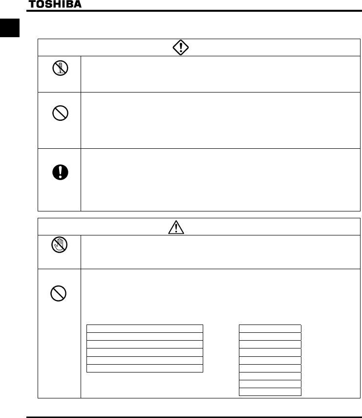
IQGeneral Operation
Danger
Disassembly
prohibited
•Never disassemble, modify or repair.
This can result in electric shock, fire and injury. For repairs, call your sales distributor.
Prohibited
•Never remove the front cover when power is on or open door if enclosed in a cabinet.
The unit contains many high voltage parts and contact with them will result in electric shock.
•Don't stick your fingers into openings such as cable wiring hole and cooling fan covers.
This can result in electric shock or other injury.
•Don't place or insert any kind of object into the inverter (electrical wire cuttings, rods, wires etc.).
This can result in electric shock or fire.
•Do not allow water or any other fluid to come in contact with the inverter.
This can result in electric shock or fire.
Mandatory
•Turn power on only after attaching the front cover or closing door if enclosed in a cabinet.
If power is turned on without the front cover attached or closing door if enclosed in a
cabinet, this can result in electric shock or other injury.
•If the inverter begins to emit smoke or an unusual odor, or unusual sounds, immediately turn power off.
If the equipment is continued in operation in such a state, the result may be fire. Call your local sales
agency for repairs.
•Always turn power off if the inverter is not used for long periods of time since there is a possibility of
malfunction caused by leaks, dust and other material. If power is left on with the inverter in that state, it
may result in fire.
Warning
Prohibited
contact
•Do not touch heat radiating fins or discharge resistors.
These device are hot, and you'll get burned if you touch them.
Prohibited
•Avoid operation in any location where there is direct spraying of the following solvents or other
chemicals.
The plastic parts may be damaged to a certain degree depending on their shape, and there is a
possibility of the plastic covers coming off.
If the chemical or solvent is anything other than those shown below, please contact us in advance.
(Table 1) Examples of applicable chemicals
and solvents
Acetic acid (density of 10% or less)
Hydrochloric acid (density of 10% or less)
Sulfuric acid (density of 10% or less)
Sodium chloride
Hexane
Triethylene glycol
(Table 2) Examples of unapplicable
chemicals and solvents
Acetone
Benzene
Chloroform
Ethylene chloride
Ethyl acetate
Glycerin
Tetrachloroethylene
Trichloroethylene
Xylene
E6581160
3
I
QTransportation & installation
Danger
Prohibited
•Do not install or operate the inverter if it is damaged or any component is missing.
This can result in electric shock or fire. Please consult your local sales agency for repairs. Call your
local sales agency for repairs.
•Do not place any inflammable objects nearby.
If a flame is emitted due to malfunction, it may result in a fire.
•Do not install in any location where the inverter could come into contact with water or other fluids.
This can result in electric shock or fire.
Mandatory
•Must be used in the environmental conditions prescribed in the instruction manual.
Use under any other conditions may result in malfunction.
•Mount the inverter on a metal plate.
The rear panel gets very hot. Do not install in an inflammable object, this can result in fire.
•Do not operate with the front panel cover removed. This can result in electric shock. Failure to do so
can lead to risk of electric shock and can result in death or serious injury.
•An emergency stop device must be installed that fits with system specifications (e.g. shut off input
power then engage mechanical brake). Operation cannot be stopped immediately by the inverter
alone, thus risking an accident or injury.
•All options used must be those specified by Toshiba.
The use of any other option may result in an accident.
Warning
Prohibited
•When transporting or carrying, do not hold by the front panel covers.
The covers may come off and the unit will drop out resulting in injury.
•Do not install in any area where the unit would be subject to large amounts of vibration.
That could result in the unit falling, resulting in injury.
Mandatory
•The main unit must be installed on a base that can bear the unit's weight.
If the unit is installed on a base that cannot withstand that weight, the unit may fall resulting in injury.
•If braking is necessary (to hold motor shaft), install a mechanical brake.
The brake on the inverter will not function as a mechanical hold, and if used for that purpose, injury
may result.
QWiring
Danger
Prohibited
•Do not connect input power to the output (motor side) terminals (U/T1,V/T2,W/T3).
That will destroy the inverter and may result in fire.
•Do not connect resistors to the DC terminals (across PA-PC or PO-PC).
That may cause a fire.
•Within ten minutes after turning off input power, do not touch wires of devices (MCCB) connected to the
input side of the inverter.
That could result in electric shock.
E6581160
4
I Danger
Mandatory
•Electrical installation work must be done by a qualified expert.
Connection of input power by someone who does not have that expert knowledge may result in fire or
electric shock.
•Connect output terminals (motor side) correctly.
If the phase sequence is incorrect, the motor will operate in reverse and that may result in injury.
•Wiring must be done after installation.
If wiring is done prior to installation that may result in injury or electric shock
•The following steps must be performed before wiring.
(1) Turn off all input power.
(2) Wait at least ten minutes and check to make sure that the charge lamp is no longer lit.
(3) Use a tester that can measure DC voltage (800VDC or more), and check to make sure that the
voltage to the DC main circuits (across PA-PC) is 45V or less.
If these steps are not properly performed, the wiring will cause electric shock.
•Tighten the screws on the terminal board to specified torque.
If the screws are not tightened to the specified torque, it may lead to fire.
•Check to make sure that the input power voltage is +10%, -15% of the rated power voltage written on
the rating label (±10% when the load is 100% in continuous operation).
If the input power voltage is not +10%, -15% of the rated power voltage (±10% when the load is 100%
in continuous operation) this may result in fire.
Be Grounded
•Ground must be connected securely.
If the ground is not securely connected, it could lead to electric shock or fire when a malfunction or
current leak occurs.
Warning
Prohibited
•Do not attach equipment (such as noise filters or surge absorbers) that have built-in capacitors to the
output (motor side) terminals.
That could result in a fire.
QOperations
Danger
Prohibited
•Do not touch inverter terminals when electrical power is going to the inverter even if the motor is
stopped.
Touching the inverter terminals while power is connected to it may result in electric shock.
•Do not touch switches when the hands are wet and do not try to clean the inverter with a damp cloth.
Such practices may result in electric shock.
•Do not go near the motor in alarm-stop status when the retry function is selected.
The motor may suddenly restart and that could result in injury.
Take measures for safety, e.g. attaching a cover to the motor, against accidents when the motor
unexpectedly restarts.
Mandatory
•Turn input power on after attaching the front cover.
When installed inside a cabinet and using with the front cover removed, always close the cabinet doors
first and then turn power on. If the power is turned on with the front cover or the cabinet doors open, it
may result in electric shock.
•Make sure that operation signals are off before resetting the inverter after malfunction.
If the inverter is reset before turning off the operating signal, the motor may restart suddenly causing
injury.
E6581160
5
I
Warning
Prohibited
•Observe all permissible operating ranges of motors and mechanical equipment. (Refer to the motor's
instruction manual.)
Not observing these ranges may result in injury.
When sequence for restart after a momentary failure is selected (inverter)
Warning
Mandatory
•Stand clear of motors and mechanical equipment.
If the motor stops due to a momentary power failure, the equipment will start suddenly after power
recovers. This could result in unexpected injury.
•Attach warnings about sudden restart after a momentary power failure on inverters, motors and
equipment for prevention of accidents in advance.
When retry function is selected (inverter)
Warning
Mandatory
•Stand clear of motors and equipment.
If the motor and equipment stop when the alarm is given, selection of the retry function will restart them
suddenly after the specified time has elapsed. This could result in unexpected injury.
•Attach warnings about sudden restart in retry function on inverters, motors and equipment for
prevention of accidents in advance.
Maintenance and inspection
Danger
Prohibited
•Do not replace parts.
This could be a cause of electric shock, fire and bodily injury. To replace parts, call the local sales
agency.
Mandatory
•The equipment must be inspected every day.
If the equipment is not inspected and maintained, errors and malfunctions may not be discovered and
that could result in accidents.
•Before inspection, perform the following steps.
(1) Turn off all input power to the inverter.
(2) Wait at least ten minutes and check to make sure that the charge lamp is no longer lit.
(3) Use a tester that can measure DC voltages (800VDC or more), and check to make sure that the
voltage to the DC main circuits (across PA-PC) is 45V or less.
If inspection is performed without performing these steps first, it could lead to electric shock.

E6581160
6
Contents
I Safety precautions .........................................................................................................................................................1
1. Read first........................................................................................................................................................................7
1.1 Check product purchase ....................................................................................................................................7
1.2 Contents of the product......................................................................................................................................9
1.3 Installation..........................................................................................................................................................9
2. Connection.....................................................................................................................................................................10
2.1 Standard connections ........................................................................................................................................10
2.2 Description of terminals......................................................................................................................................12
3. Operations .....................................................................................................................................................................19
3.1 Simplified operation of the VF-S11.....................................................................................................................19
3.2 How to operate the VF-S11................................................................................................................................23
4. Basic VF-S11 operations................................................................................................................................................27
4.1 Flow of status monitor mode ..............................................................................................................................28
4.2 How to set parameters .......................................................................................................................................29
5. Monitoring the operation status......................................................................................................................................36
5.1 Status monitor mode ..........................................................................................................................................36
5.2 Display of trip information...................................................................................................................................40
6. Measures to satisfy the standards .................................................................................................................................44
6.1 How to cope with the CE directive .....................................................................................................................44
6.2 Compliance with UL Standard and CSA Standard.............................................................................................48
7. Table of parameters and data ........................................................................................................................................50
7.1 User parameters ................................................................................................................................................50
7.2 Basic parameters ...............................................................................................................................................50
7.3 Extended parameters.........................................................................................................................................53
8. Specifications.................................................................................................................................................................70
8.1 Models and their standard specifications ...........................................................................................................70
8.2 Outside dimensions and mass ...........................................................................................................................73
9. Before making a service call - Trip information and remedies........................................................................................76
9.1 Trip causes/warnings and remedies...................................................................................................................76
E6581160
7
1
1. Read first
Thank you for your purchase of the Toshiba “TOSVERT VF-S11” industrial inverter.
This manual is a simplified version.
If you need a detailed explanation, refer to the full version of English manual (E6581158).
This is the Ver. 108 / Ver. 109 CPU version inverter.
Please be informed that CPU version will be frequently upgraded.
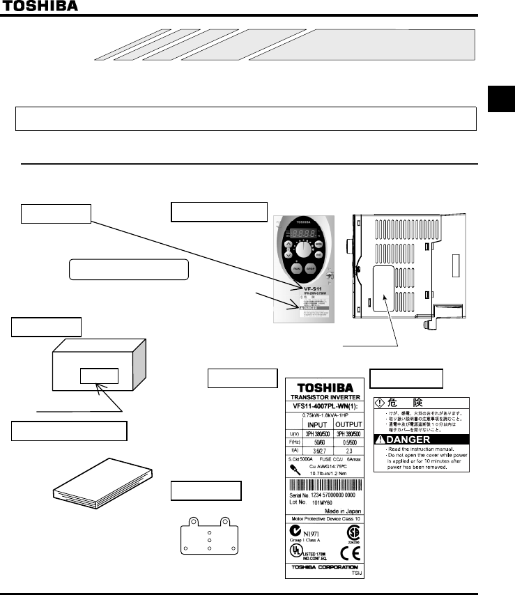
1.1 Check product purchase
Before using the product you have purchased, check to make sure that it is exactly what you ordered.
Related output
current
Power supply
Related input current
Inverter Type
Inverter rated output
capacity
Warning label
Power supply
Motor capacity
Series name
Rating label Inverter main unit
Carton box
Name plate Warning label
VF-S11
1PH-200/240V-0.75kW/1HP
Instruction manual
This manual
Name plate
Type indication label
EMC plate
E6581160
8
1
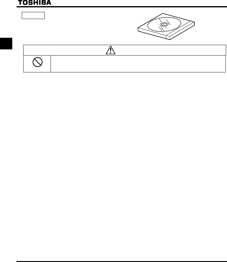
CD-ROM E6581167
Contains the instruction manual in digital form.
Some models do not come with this CD-ROM.
Warning
Prohibited
Do not play this CD-ROM on any audio CD player to avoid hearing loss due to very loud noises or
damage to the CD player.
[System requirements]
OS: Microsoft Windows 98/NT/2000/XP
Browser: Internet Explorer 4.0 or later
CPU: Pentium 100MHz or more
Memory: 32MB or more
DOS/V-based personal computer
[Starting the browsing program]
When you insert this CD-ROM in the CD-ROM drive, the program “index.htm” in the root directory starts automatically.
When you want to close the browsing program or if it does not start automatically, open Windows Explorer and click
“\index.htm” under “CD-ROM drive” to display the top window.
[Software needed for browsing]
Adobe Acrobat Reader 4.0J or later
[Trade names and trademarks]
・Microsoft Windows and Windows logos are trademarks or registered trademarks of Microsoft Corporation in the U.S.A.
・Adobe Acrobat is a trademark of Adobe Systems Incorporated.
・Other company names and product names referred to in this manual are trade names and registered trademarks,
respectively.
[Copyright]
This manual and other documentation included with the inverter are publications of Toshiba Schneider Inverter
Corporation, and all rights to these publications, including copyrights, are reserved by the said corporation.
[Duplication]
No part of the contents of the CD-ROM shall be reproduced without written permission from Toshiba Schneider Inverter
Corporation.
[Exclusions]
Toshiba Schneider Inverter Corporation shall have no liability for any damage of any kind caused by the use of this CD-
ROM.
E6581160
9
1
1.2 Contents of the product
Explanation of the name plate label. Always shut power off first then check the ratings label of inverter held in a
cabinet.
Type Form
VFS11S -2007PLE-WN -A22
Model name
TOSVERT
VF-S11series
Number of
power phases
S: sin
g
le-
p
hase
None:
three-
p
hase
Applicable motor
capacity
002 : 0.2kW
004 : 0.4kW
005 : 0.55kW
007 : 0.75kW
015 : 1.5kW
022 : 2.2kW
037 : 3.7kW
055 : 5.5kW
075 : 7.5kW
110 : 11kW
150 : 15kW
Additional functions I
None: No filter inside
M: Built-in basic filter
L: Built-in
high-attenuation
EMI filter
Operation panel
P: Provided
Default interface
logic*
WN, AN : Negative
WP : Positive
Special specification code
A:is the number
Input (AC) voltage
2 : 200V to 240V
4 : 380V to 500V
6 : 525V to 600V
Additional function II
None: Standard product
E: Enclosed type
U: Open type
R: With a built-in RS-485
circuit board
* This code represents the factory default logic setting. You can switch from one input/output logic to the other using
slide switch SW1.
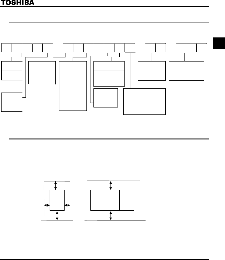
1.3 Installation
Install the inverter in a well-ventilated indoor place and mount it on a flat metal plate in portrait orientation.
If you are installing more than one inverter, the separation between inverters should be at least 5 centimeters,
and they should be arranged in horizontal rows. If the inverters are horizontally arranged with no space
between them (side-by-side installation), peel off the ventilation seals on top of the inverter. It is necessary to
decrease the current if the inverter is operated at over 50°C.
•
••
•Standard installation •
••
•Side-by-side installation
5 cm or more 5 cm or more
10 cm or more
10 cm or more
Remove seals on top
VFS11 VFS11 VFS11 VFS11
10 cm or more
10 cm or more
The space shown in the diagram is the minimum allowable space. Because air cooled equipment has cooling
fans built in on the top or bottom surfaces, make the space on top and bottom as large as possible to allow
for air passage.
Note: Do not install in any location where there is high humidity or high temperatures and where there are
large amounts of dust, metallic fragments and oil mist.
E6581160
10
2
2. Connection
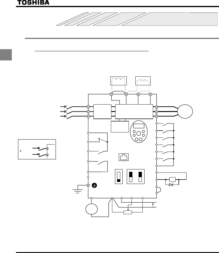
2.1 Standard connections
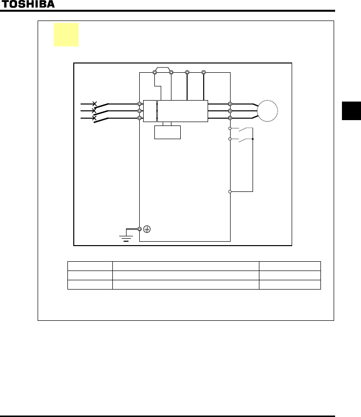
2.1.1 Standard connection diagram 1
This diagram shows a standard wiring of the main circuit.
MCCB
*1
R/L1
S/L2
T/L3
U/T1
V/T2
W/T3 I M
FLC
FLB
FLA
RY
RC
PLC
Motor
F
R
RES
S1
S2
S3
CC
P24
OUT
NO
CC
FM
PLC
CC VIA VIB PP
++
-
-
P0 PA/+ PB PC/-
Meter Voltage signal: 0-10V
(Current signal: 4-20mA)
External potentiometer (1~10kΩ)
(or input voltage signal across VIB-CC terminals: 0-10V)
Control
circuit
Operation panel
Protective function
activation output
Ry
VF-S11
Frequency
meter
(ammeter)
Power circuit
Noise
filter
DC reactor (DCL)
*2 (option)
Connector for
common serial
communications
Forward
Reverse
Reset
Preset-speed 1
Preset-speed 2
Preset-speed 3
Common
Braking resistor (option)
Standard connection diagram - SINK (Negative) (common:CC)
Low-speed
signal output
24Vdc input
7.5V-1mA
(or 4-20mA)
MCCB(2P)
R/L1
S/L2
Power supply
1 200~240V
-50/60Hz
Speed reach
signal output
I ISINK
SW1
SOURCE
FM
V
VIA
V
Main circuit power supply
240V class: three-phase 200-240V
-50/60Hz
500V class: three-phase 380-500V
-50/60Hz
600V class: three-phase 525-600V
-50/60Hz
*1: The T/L3 terminal is not provided
for single-phase models.
Use the R/L1 and S/L2 terminal
as input terminals.
*2: The inverter is supplied with the PO
and the PA/+ terminals shorted by
means of a shorting bar.
Before installing the DC reactor (DCL),
remove the bar.
*3: When using the OUT output terminal in
sink logic mode, short the NO and CC
terminals.
*4: If you are using a 600V model, be sure
to connect an input reactor (ACL).
*5: 600V models have no noise filter inside.
*3
*5
E6581160
11
2
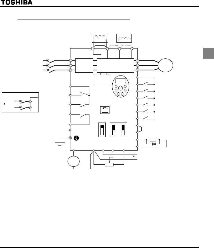
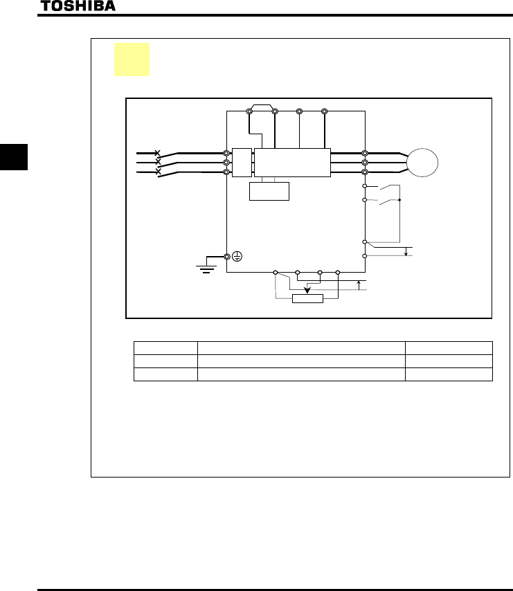
2.1.2 Standard connection diagram 2
MCCB
*1
R/L1
S/L2
T/L3
U/T1
V/T2
W/T3 I M
FLC
FLB
FLA
RY
RC
PLC
Motor
P24
F
R
RES
S1
S2
S3
P24
OUT
NO
CC
++
-
-
P0
Meter
External potentiometer (1~10kΩ)
(or input voltage signal across VIB-CC terminals: 0-10V)
Control
circuit
Operation panel
Protective function
activation output
VF-S11
Frequency
meter
(ammeter)
Power circuit
Noise
filter
*1: The T/L3 terminal is not provided
for single-phase models.
Use the R/L1 and S/L2 terminal
as input terminals.
*2: The inverter in supplied with the PO
and the PA/+ terminals shorted by
means of a shorting bar.
Before installing the DC reactor (DCL),
remove the bar.
*3: When using the NO output terminal in
source logic mode, short the P24 and
OUT terminals.
*4: If you are using a 600V model, be sure
to connect an input reactor (ACL).
*5: 600V models have no noise filter inside.
DC reactor (DCL)
*2 (option)
Connector for
common serial
communications
Forward
Reverse
Reset
Preset-speed 1
Preset-speed 2
Preset-speed 3
Braking resistor (option)
Standard connection diagram - SOURCE (Positive) (common:P24)
Low-speed
signal output
24Vdc input
7.5V-1mA
(or 4-20mA)
MCCB(2P)
R/L1
S/L2
Main circuit power supply
240V class: three-phase 200-240V
-50/60Hz
500V class: three-phase 380-500V
-50/60Hz
600V class: three-phase 525-600V
-50/60Hz
Power supply
1 200
~
240V
-50/60Hz
FM CC VIA VIB PP
PLC
PA/+ PB PC/-
Voltage signal: 0-10V
(Current signal: 4-20mA)
IISINK
SW1
SOURCE
FM
V
VIA
V
*5
Speed reach signal
output
*3
Ry
E6581160
12
2
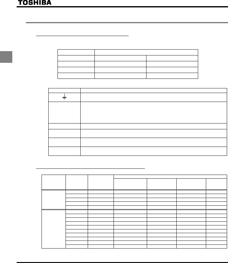
2.2 Description of terminals
2.2.1 Power circuit terminals
In case of the lug connector, cover the lug connector with insulated tube, or use the insulated lug
connector.
Screw size tightening torque
M3.5 screw 0.9Nm 7.1lb y in
M4 screw 1.3Nm 10.7lb y in
M5 screw 2.5Nm 22.3lb y in
M6 screw 4.5Nm 40.1lb y in
QPower circuit
Terminal symbol Terminal function
Grounding terminal for connecting inverter. There are 3 terminals in total. 2 terminals in
the terminal board, 1 terminal in the cooling fin.
R/L1,S/L2,T/L3
240V class: single-phase 200 to 240V-50/60Hz
three-phase 200 to 240V-50/60Hz
500V class: three-phase 380 to 500V-50/60Hz
600V class: three-phase 525 to 600V-50/60Hz
* Single-phase input: R/L1 and S/L2 terminals
U/T1,V/T2,W/T3 Connect to a (three-phase induction) motor.
PA/+,PB Connect to braking resistors.
Change parameters H, H, H, H if necessary.
PC/- This is a negative potential terminal in the internal DC main circuit. DC common power
can be input across the PA terminals (positive potential).
PO,PA/ + Terminals for connecting a DC reactor (DCL: optional external device). Shorted by a
short bar when shipped from the factory. Before installing DCL, remove the short bar.
2.2.2 Selection of wiring materials
Wire size (See Note 4)
Voltage class
Capacity of
applicable
motor (kW)
Inverter model Power circuit
(mm2) (Note 1.)
DC reactor
(optional) (mm2)
Braking resistor/
Braking unit
(optional) (mm2)
Earth cable
(mm2)
0.2 VFS11S-2002PL 2.0 (2.0) 2.0 2.0 3.5
0.4 VFS11S-2004PL 2.0 (2.0) 2.0 2.0 3.5
0.75 VFS11S-2007PL 2.0 (2.0) 2.0 2.0 3.5
1.5 VFS11S-2015PL 2.0 (2.0) 2.0 2.0 3.5
Single-phase
240V class
2.2 VFS11S-2022PL 2.0 (2.0) 3.5 2.0 3.5
0.4 VFS11-2004PM 2.0 (2.0) 1.25 2.0 3.5
0.55 VFS11-2005PM 2.0 (2.0) 2.0 2.0 3.5
0.75 VFS11-2007PM 2.0 (2.0) 2.0 2.0 3.5
1.5 VFS11-2015PM 2.0 (2.0) 2.0 2.0 3.5
2.2 VFS11-2022PM 2.0 (2.0) 2.0 2.0 3.5
4.0 VFS11-2037PM 2.0 (2.0) 3.5 2.0 3.5
5.5 VFS11-2055PM 5.5 (2.0) 8.0 2.0 5.5
7.5 VFS11-2075PM 8.0 (5.5) 14 3.5 5.5
11 VFS11-2110PM 14 (8.0) 14 5.5 8.0
Three-phase
240V class
15 VFS11-2150PM 22 (14) 22 14 8.0
E6581160
13
2
Wire size (See Note 4)
Voltage class
Capacity of
applicable
motor (kW)
Inverter model Power circuit
(mm2) (Note 1.)
DC reactor
(optional) (mm2)
Braking resistor/
Braking unit
(optional) (mm2)
Earth cable
(mm2)
0.4 VFS11-4004PL 2.0 (2.0) 2.0 2.0 3.5
0.75 VFS11-4007PL 2.0 (2.0) 2.0 2.0 3.5
1.5 VFS11-4015PL 2.0 (2.0) 2.0 2.0 3.5
2.2 VFS11-4022PL 2.0 (2.0) 2.0 2.0 3.5
4.0 VFS11-4037PL 2.0 (2.0) 2.0 2.0 3.5
5.5 VFS11-4055PL 2.0 (2.0) 3.5 2.0 3.5
7.5 VFS11-4075PL 3.5 (2.0) 5.5 2.0 3.5
11 VFS11-4110PL 5.5 (2.0) 8.0 2.0 5.5
Three-phase
500V class
15 VFS11-4150PL 8.0 (5.5) 14 3.5 5.5
0.75 VFS11-6007P 2.0 2.0 2.0 3.5
1.5 VFS11-6015P 2.0 2.0 2.0 3.5
2.2 VFS11-6022P 2.0 2.0 2.0 3.5
4.0 VFS11-6037P 2.0 2.0 2.0 3.5
5.5 VFS11-6055P 2.0 2.0 2.0 3.5
7.5 VFS11-6075P 2.0 2.0 2.0 3.5
11 VFS11-6110P 3.5 3.5 2.0 3.5
Three-phase
600V class
15 VFS11-6150P 5.5 5.5 2.0 5.5
Note 1: Sizes of the wires connected to the input terminals R/L1, S/L2 and T/L3 and the output terminals U/T1,
V/T2 and W/T3 when the length of each wire does not exceed 30m.
The numeric values in parentheses refer to the sizes of wires to be used when a DC reactor is connected.
Note 2: For the control circuit, use shielded wires 0.75 mm2 or more in diameter.
Note 3: For grounding, use a cable with a size equal to or larger than the above.
Note 4: The wire sizes specified in the above table apply to HIV wires (cupper wires shielded with an insulator
with a maximum allowable temperature of 75°C) used at an ambient temperature of 50°C or less.
Note 5: If there is a need to bring the inverter into UL compliance, use wires specified in Chapter 6.
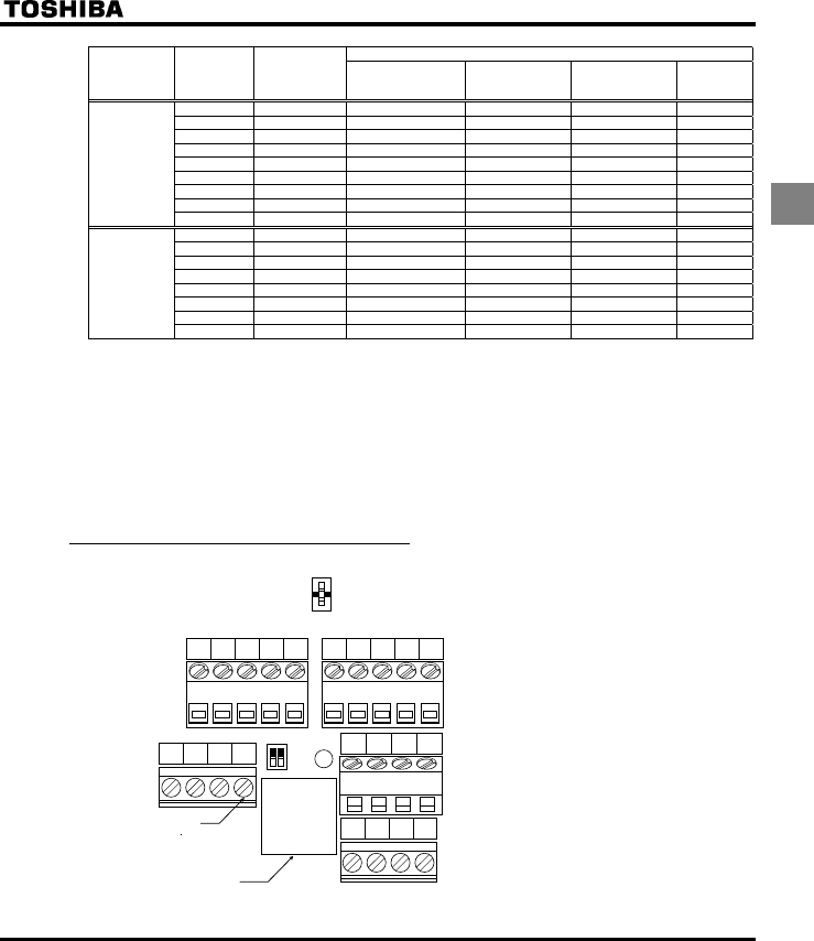
2.2.3 Control circuit terminals
P24
PP VIA VIB CC
PLC S1 S2 S3
FM VIA
PLC
SOURCE
SINK
SW1
OUT NO FM CC FLA FLB FLC RY RC
F R RES CC
V
I
V
I
Optional connector
(RJ45)
M3 screw
(0.5N m)
Factory default settings of slide switches
SW1: SINK (Negative) side (WN, AN type)
SOURCE (Positive) side (WP type)
FM: V side
VIA: V side
Wire size
Solid wire: 0.3 ∼ 1.5 (mm2)
Stranded wire: 0.3 ∼ 1.5 (mm2)
(AWG 22 ∼ 16)
Sheath strip length: 6 (mm)
Screwdriver: Small-sized flat-blade screwdriver
(Blade thickness: 0.4 mm or less,
blade width: 2.2 mm or less)
The control circuit terminal
board is common to all
equipment.
E6581160
14
2
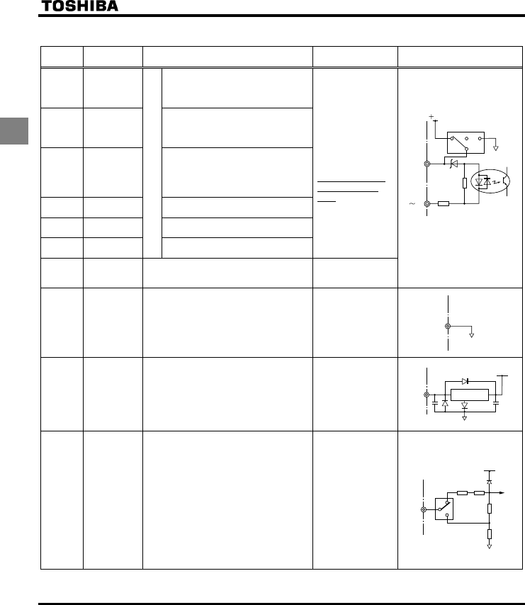
QControl circuit terminals
Terminal
symbol Input/output Function Electrical
specifications Inverter internal circuits
F Input
Shorting across F-CC causes
forward rotation; open causes slow-
down and stop. (When ST is always
ON)
R Input
Shorting across R-CC causes
reverse rotation; open causes slow-
down and stop. (When ST is always
ON)
RES Input
This inverter protective function is
disabled if RES are CC is connected.
Shorting RES and CC has no effect
when the inverter is in a normal
condition.
S1 Input Shorting across S1-CC causes
preset speed operation.
S2 Input Shorting across S2-CC causes
preset speed operation.
S3 Input
Multifunction programmable contact input
Shorting across S3-CC causes
preset speed operation.
No voltage
contact input
24Vdc-5mA or less
*Sink/Source/PLC
selectable using
SW1
PLC Input
(common)
External 24Vdc power input
When the source logic is used, a common
terminal is connected.
24VDC
(Insulation
resistance: DC50V)
Factory default setting
WN, AN type : SINK side
WP type : SOURCE side
CC Common to
Input/output
Control circuit's equipotential terminal (3
terminals)
PP Output Analog power supply output
10Vdc
(permissible load
current: 10mA)
VIA Input
Multifunction programmable analog input.
Factory default setting: 0~10Vdc and
0~60Hz (0~50Hz) frequency input.
The function can be changed to
4~20mAdc (0~20mA) current input by
flipping the dip switch to the I position.
By changing parameter setting, this
terminal can also be used as a
multifunction programmable contact input
terminal. When using the sink logic, be
sure to insert a resistor between P24-VIA
(4.7 kΩ―1/2 W). Also move the VIA dip
switch to the V position.
10Vdc
(internal impedance:
30kΩ)
4-20mA
(internal impedance:
250Ω)
CC
PLC
4.7K
24V
SOURCE
SW1
PLC
SINK
820
FS3
PP
0.47µ
+24V
conversion
Voltage
+5V
15k
15k
250
300
VIA
VIA
V
I
E6581160
15
2
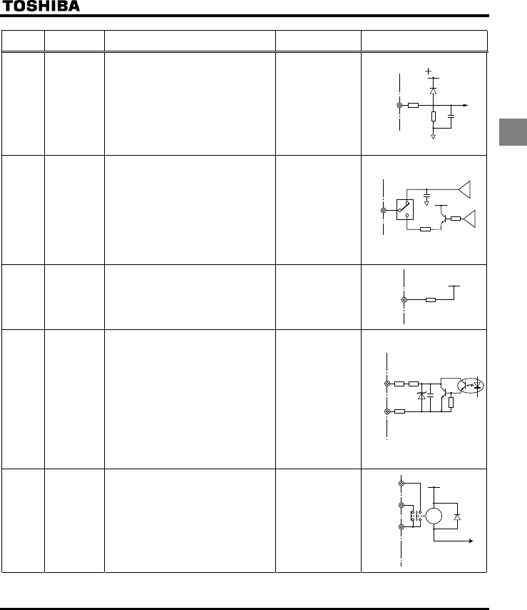
Terminal
symbol Input/output Function Electrical
specifications Inverter internal circuits
VIB Input
Multifunction programmable analog input.
Standard default setting: 0~10Vdc input
and 0~60Hz (0~50Hz) frequency
By changing parameter setting, this
terminal can also be used as a
multifunction programmable contact input
terminal. When using the sink logic, be
sure to insert a resistor between P24 and
VIB. (4.7 kΩ―1/2 W)
10Vdc
(internal
impedance: 30kΩ)
FM Output
Multifunction programmable analog
output. Standard default setting: output
frequency.
The function can be changed to 0-20mAdc
(4-20mA) current output by flipping the FM
slide switch to the I position.
1mAdc full-scale
ammeter or 7.5Vdc
(10Vdc)1mA full-
scale voltmeter
0-20mA (4-20mA)
DC ammeter
Permissible load
resistance:
750Ω or less
P24 Output 24Vdc power output 24Vdc-100mA
OUT
NO Output
Multifunction programmable open collector
output. Standard default settings detect
and output speed reach signal output
frequencies.
Multifunction output terminals to which two
different functions can be assigned.
The NO terminal is an isoelectric output
terminal. It is insulated from the CC
terminal.
By changing parameter settings, these
terminals can also be used as
multifunction programmable pulse train
output terminals.
Open collector output
24Vdc-50mA
To output pulse
trains,
a current of 10mA
or more needs to
be passed.
Pulse frequency
range:
38~1600Hz
FLA
FLB
FLC
Output
Multifunction programmable relay contact
output.
Detects the operation of the inverter's
protection function.
Contact across FLA-FLC is closed and FLB-
FLC is opened during protection function
operation.
250Vac-1A
(cosφ=1)
: at resistance load
30Vdc-0.5A
250Vac-0.5A
(cosφ=0.4)
* PTC (Positive Temperature Coefficient): Resettable thermal fuse resistor for over current protection.
P24
4.7K
100
FM
FM
V
I
+
-
+
-
15k
5V
VIB
15k
PTC*
+24V
P24
10
10
PTC*
OUT
NO
FLB
FLC
FLA +24V
RY
E6581160
16
2
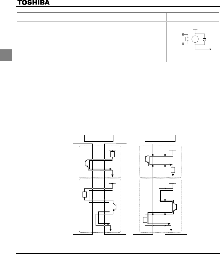
Terminal
symbol Input/output Function Electrical
specifications Inverter internal circuits
RY
RC Output
Multifunction programmable relay contact
output.
Standard default settings detect and
output low-speed signal output
frequencies.
Multifunction output terminals to which two
different functions can be assigned.
250Vac-1A
(cosφ=1)
: at resistance load
30Vdc-0.5A
250Vac-0.5A
(cosφ=0.4)
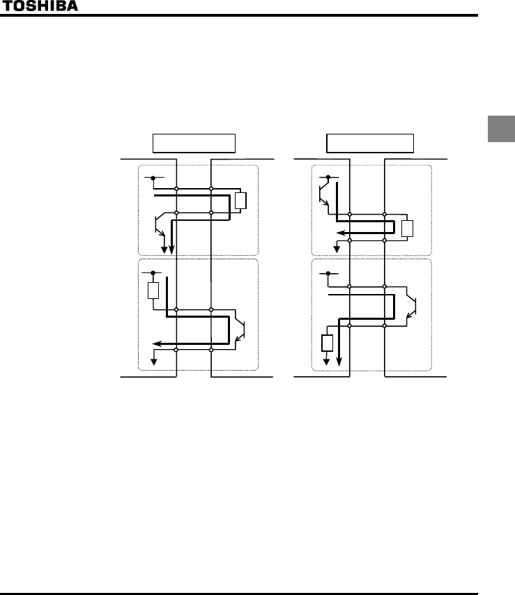
QSINK (Negative) logic/SOURCE (Positive) logic (When the
inverter's internal power supply is used)
Current flowing out turns control input terminals on. These are called sink logic terminals. (Type: -AN/-WN).
The general used method in Europe is source logic in which current flowing into the input terminal turns it
on (Typ: -WP).
Sink logic is sometimes referred to as negative logic, and source logic is referred to as positive logic.
Each logic is supplied with electricity from either the inverter's internal power supply or an external power
supply, and its connections vary depending on the power supply used.
<Examples of connections when the inverter's internal power supply is used>
CC
NO
Source (Positive) logic
Inverter
P24
F
Programmable
controller
Common
Common
Output
Input
Input
24VDC
Output
Sink (Negative) logic
F
CC
Common
Output
Input
24VDC
Output
OUT
P24
24VDC
CC
NO
OUT
P24
24VD
Input
Common
Inverter
Programmable
controller
Slide switch SW1:SINK Slide switch SW1:SOURCE
+24V
RY
RY
RC
E6581160
17
2
QSINK (Negative) logic/SOURCE (Positive) logic (When an external power supply
is used)
The PLC terminal is used to connect to an external power supply or to insulate a terminal from other input
or output terminals. As for input terminals, turn the SW1 slide switch to the PLC position.
<Examples of connections when an external power supply is used>
Sink (Negative) logic
Inverter
PLC
F
Programmable
controller
Common
Output
Input
24VDC
Output
F
Output
Input
24VDC
Output
OUT
NO
24VDC
Input
Common
Inverter
Programmable
controller
Slide switch SW1:PLC Slide switch SW1:PLC
PLC
Common
24VDC
OUTCommon
NO
Input
Source (Positive) logic
QSelecting the functions of the VIA and VIB terminals between analog input and
contact input
The functions of the VIA and VIB terminals can be selected between analog input and contact input by
changing parameter settings (H). (Factory default setting: Analog input)
When using these terminals as contact input terminals in a sink logic circuit, be sure to insert a resistor
between the P24 and VIA terminals or between the P24 and VIB terminals. (Recommended resistance:
4.7KΩ-1/2W)
When using the VIA terminal as a contact input terminal, be sure to turn the VIA switch to the V position. If
no resistor is inserted or the VIA slide switch is not turned to the V position, contact input will be left always
ON, which is very dangerous.
Switch between analog input and contact input before connecting the terminals to the control circuit
terminals. Otherwise the inverter or devices connected to it may be damaged.
E6581160
18
2
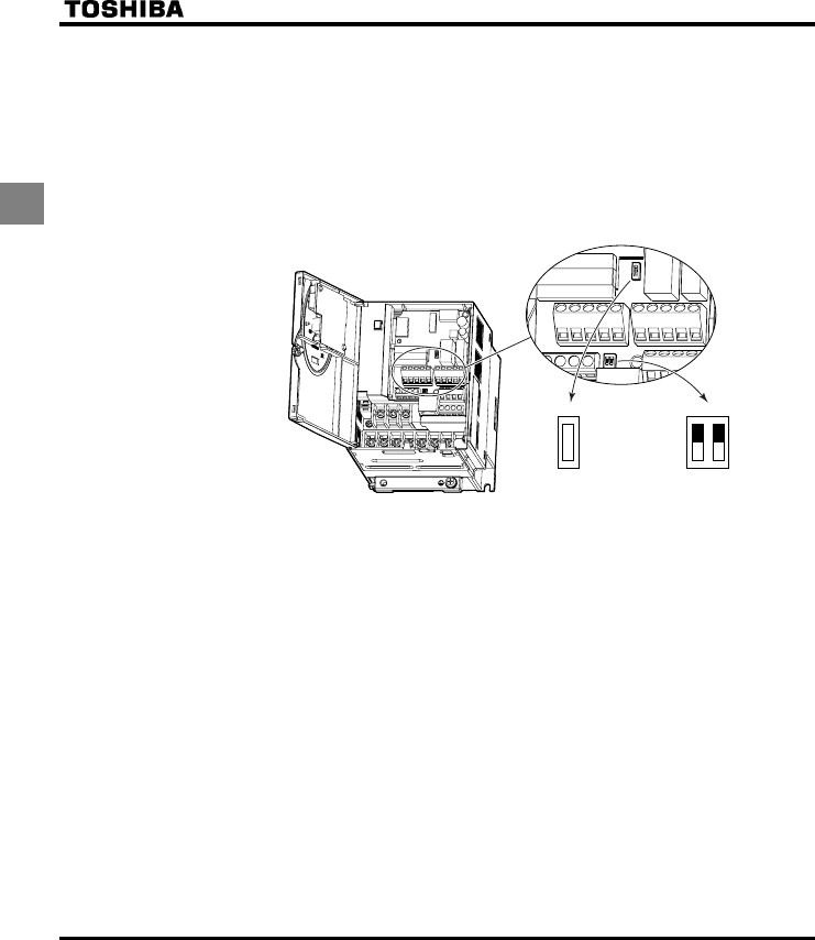
QLogic switching/Voltage-current output switching (slide switch)
(1) Logic switching
Use SW1 to switch between logics.
Switch between logics before wiring to the inverter and without supplying power. If switching between
sink, source and PLC is done when power is turned on after switching or when the inverter is supplied
with power, the inverter might become damaged. Confirm it before supplying power.
(2) Voltage-current output switching
Use the FM switch to switch between voltage output and current output.
Switch the FM terminal's voltage-current output before wiring to inverter or without supplying power.
PLC
SW1
SOURCE
FM VIA
SINK
V
I
V
I
Factory default settings of slide switches
SW1 : SINK (Negative) side (WN, AN type)
SOURCE (Positive) side (WP type)
FM : V side
VIA : V side
E6581160
19
3
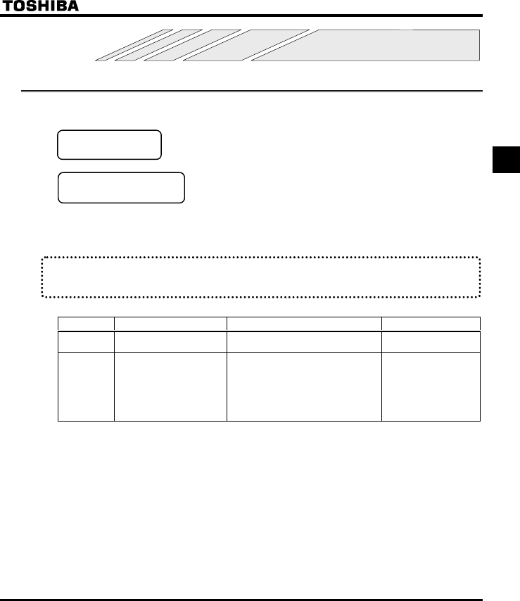
3. Operations
3.1 Simplified Operation of the VF-S11
The procedures for setting operation frequency and the methods of operation can be selected from the following.
Start / Stop :(1) Start and stop using the operation panel keys
(2) Run and stop from the operation panel
Setting the frequency :(1) Setting using the potentiometer on the inverter
main unit
(2) Setting using the operation panel
(3) Setting using external signals to the terminal board
(0-10Vdc, 4-20mAdc)
Use the basic parameters EOQF (Operation command mode selection),
HOQF (Speed setting mode selection).
Title Function Adjustment range Default setting
EOQF Command mode selection 0: Terminal board
1: Panel 1
HOQF Frequency setting mode
0: Internal potentiometer setting
1: VIA
2: VIB
3: Operation panel
4: Serial communication
5: External contact up/down
6: VIA+VIB (Override)
0
* See the manual E6581158 for HOQF=4, 5 and 6.
E6581160
20
3
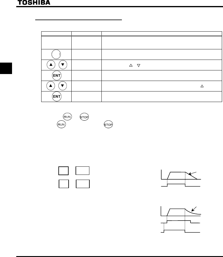
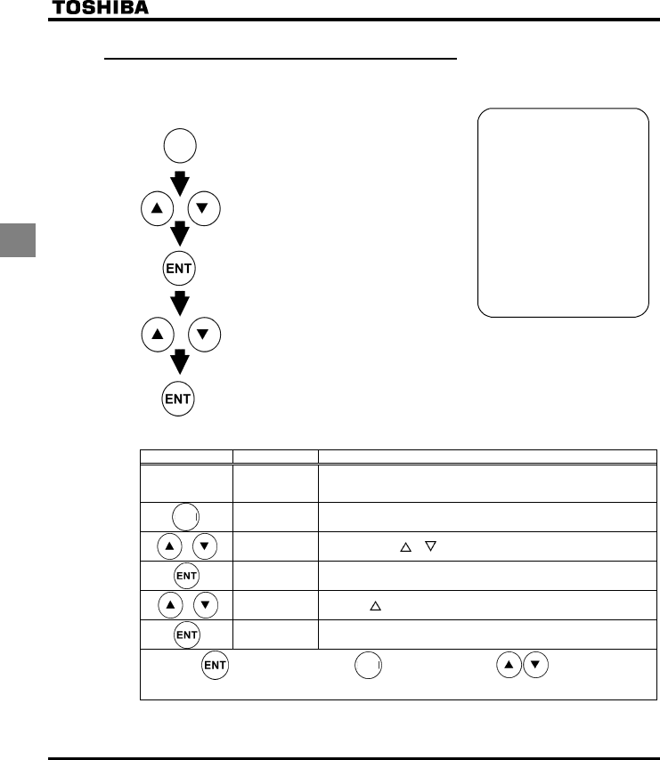
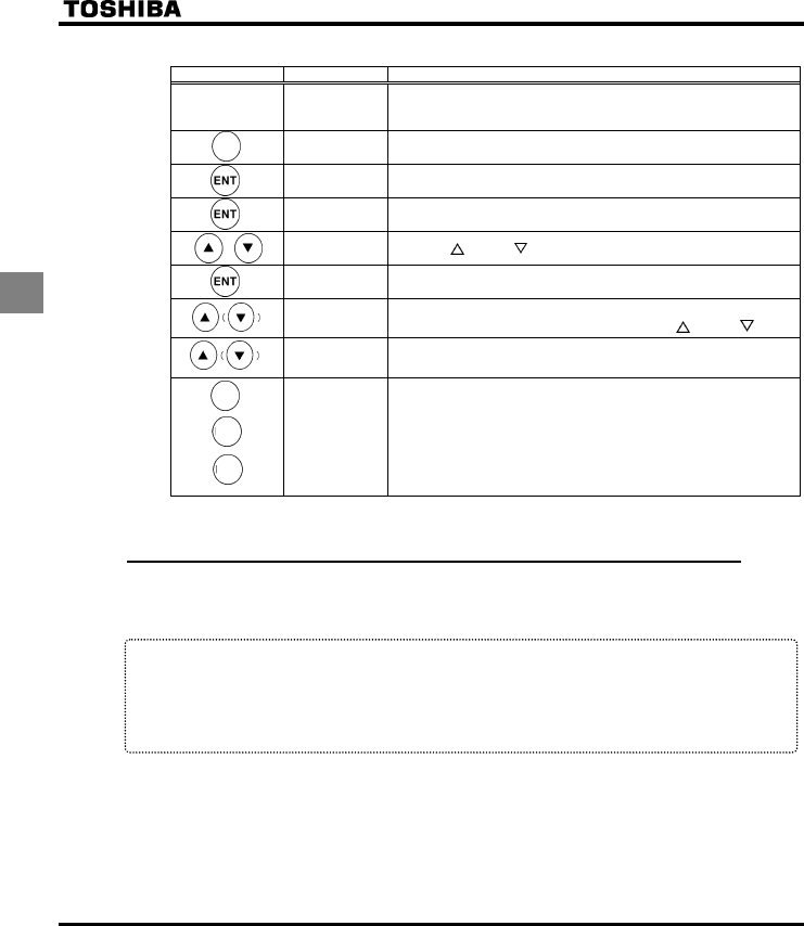
3.1.1 How to start and stop
[Example of a EOQF setting procedure]
Key operated LED display Operation
Displays the operation frequency (operation stopped).
(When standard monitor display selection H= [Operation
frequency])
CWJ Displays the first basic parameter [History (CWJ)].
EOQF Press either the or key to select “EOQF”.
Press ENTER key to display the parameter setting. (Default setting:).
Change the parameter to (terminal board) by pressing the key.
⇔EOQF Press the ENTER key to save the changed parameter. EOQF and the
parameter set value are displayed alternately.
(1) Start and stop using the operation panel keys (EOQF=)
Use the and keys on the operation panel to start and stop the motor.
: Motor starts. : Motor stops.
✩
✩✩
✩To switch between forward run and reverse run from the control panel, the parameter fr
(forward/reverse run selection) needs to be set to 2 or 3.
(2) RUN/STOP by means of an external signal to the terminal board (EOQF=):
Sink (Negative) logic
Use external signals to the inverter terminal board to start and stop the motor.
Frequency
ON
OFF
F-CC
Slow down
and stop
F
FF
F
Short and terminals: run forward
Open and terminals: slow down and stop
CC
FCC
(3) Coast stop
The standard default setting is for slowdown stop. To
make a coast stop, assign a "1(ST)" terminal function
to an idle terminal using the programmable terminal
function.
Change to H=.
For coast stop, open the ST-CC when stopping the
motor in the state described at left.The monitor on the
inverter at this time will display QHH.
Motor
speed
ON
OFF
ON
OFF
F-CC
ST-CC
Coast stop
MODE
E6581160
21
3
3.1.2 How to set the frequency
[Example of a HOQF setting procedure]
Key operated LED display Operation
Displays the operation frequency (operation stopped).
(When standard monitor display selection H= [Operation
frequency])
CWJ Displays the first basic parameter [History (CWJ)].
HOQF Press either the key or key to select “HOQF”.
Press ENTER key to display the parameter setting. (Default setting: ).
Change the parameter to (Operation panel) by pressing the key.
⇔HOQF Press the ENTER key to save the changed parameter. HOQF and the
parameter set value are displayed alternately.
* Pressing the MODE key twice returns the display to standard monitor mode (displaying operation frequency).
(1) Setting the frequency using the potentiometer on the inverter main unit
(HOQF=)
Set the frequency with the notches on the potentiometer.
Move clockwise for the higher frequencies.
The potentiometer has hysteresis. So the set value may slightly change
when the inverter is turned off, and then turned back on.
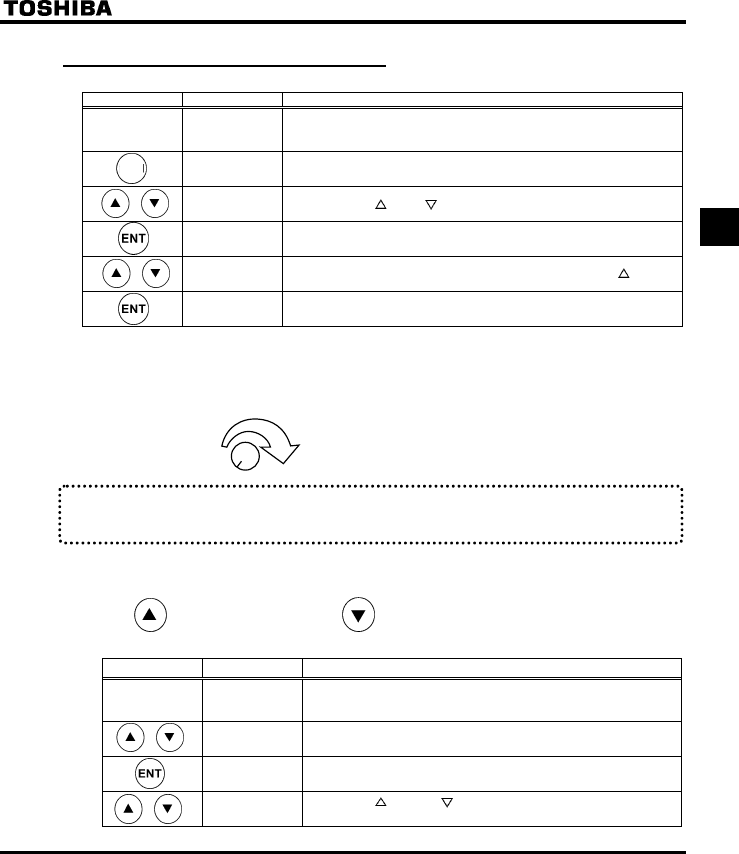
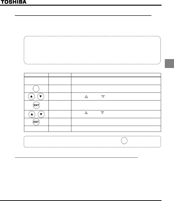
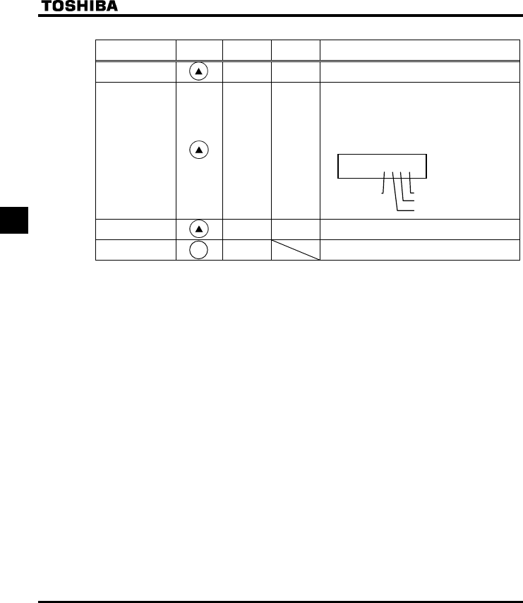
(2) Setting the frequency using the operation panel (HOQF=)
Set the frequency with the operation panel..
: Moves the frequency up : Moves the frequency down
Example of operating a run from the panel
Key operated LED display Operation
Displays the operation frequency.
(When standard monitor display selection H= [Operation
frequency])
Set the operation frequency.
⇔HE Press the ENT key to save the operation frequency. HE and the
frequency are displayed alternately.
Pressing the key or the key will change the operation frequency
even during operation.
MODE
E6581160
22
3
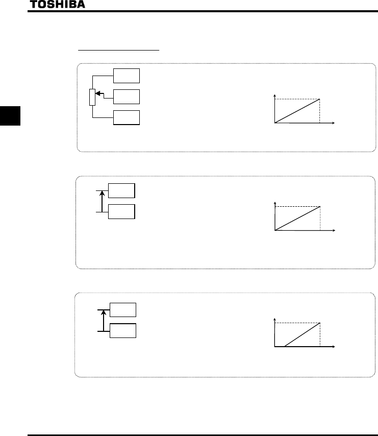
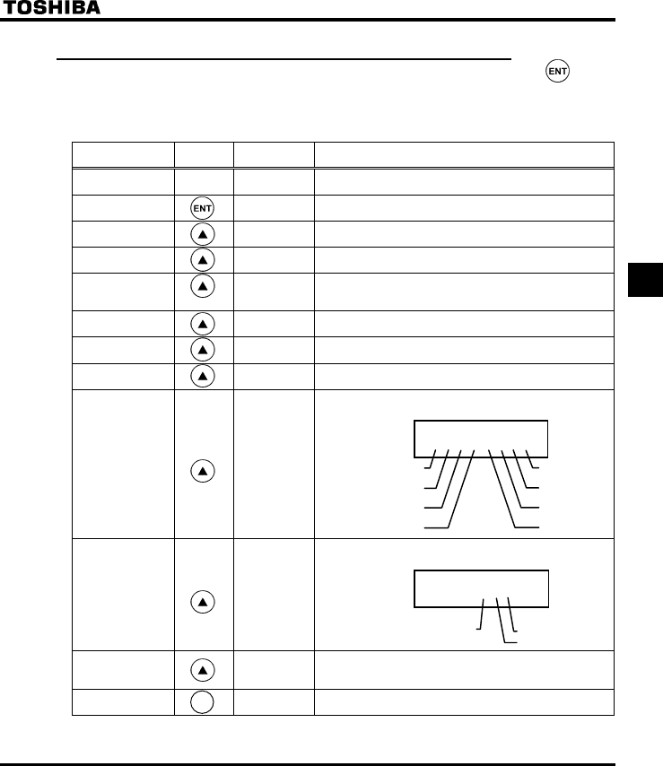
(3) Setting the frequency using the operation panel (HOQF= or )
Frequency setting
1) Setting the frequency using external potentiometer
: Setting frequency
using potentiometer
★Potentiometer
Setting frequency using the potentiometer (1-10kΩ, 1/4W)
Frequency
60Hz
0
MIN MAX
* The input terminal VIA can be used in the same way.
HOQF=: VIA effectiv e, HOQF=: VIB effective
PP
CC
V
IB
2) Setting the frequency using input voltage (0~10V)
★Voltage signal
Setting frequency using voltage signals (0∼10V).
Frequency
60Hz
0
0Vdc 10Vdc
* The input terminal VIB can be used in the same way.
HOQF=: VIA effective, HOQF=: VIB effective
Note: Be sure to turn the VIA slide switch to the V (voltage) position.
CC
V
IA+
-
: Voltage signal 0-10mAdc
3) Setting the frequency using current input (4~20mA)
★Current Signal
Current signal Setting frequency using current signals (4~20mA).
Frequency
60Hz
04mAdc 20mAdc
* Setting of parameters also allow 0-20mAdc.
Note: Be sure to turn the VIA slide switch to the I (current) position.
CC
VIA+
-
: Current signal 4-20mAdc
E6581160
23
3
3.2 How to operate the VF-S11
Overview of how to operate the inverter with simple examples.
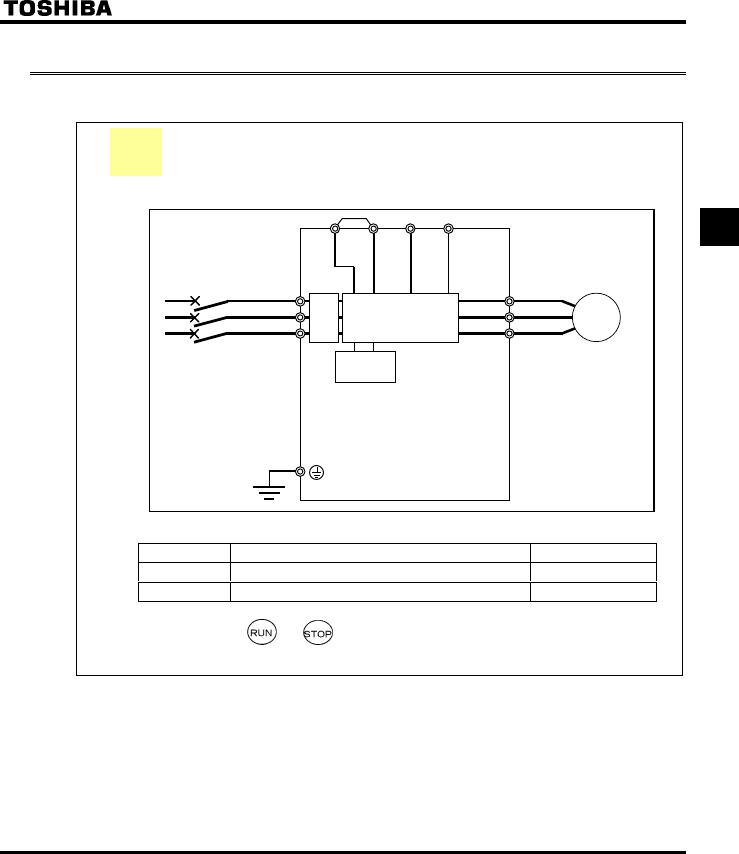
Setting the operation frequency using built-in potentiometer and
running and stopping using the operation panel.
(1) Wiring
Parameter setting (default setting)
Title Function Programmed value
EOQF Command mode selection 1
HOQF Frequency setting mode selection 1 0
(3) Operation
Run/stop: Press the and keys on the panel.
Frequency setting: Set adjusting position of notches on the potentiometer.
* 600V models have no noise filter inside.
Braking
circuit
Motor
IM
R/L1
S/L2
T/L3
U/T1
V/T2
W/T3
PO PC/-
PB
PA/+
Power circuit
MCCB
Noise
filter
*
Ex.1
E6581160
24
3
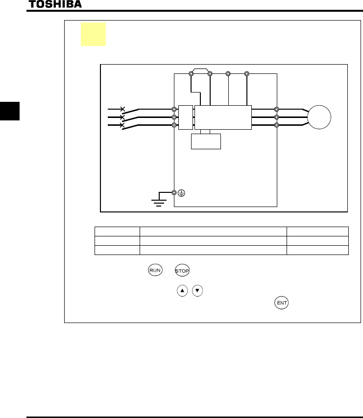
Setting the operation frequency using the operation panel and
running and stopping using the operation panel.
(1) Wiring
(2) Parameter setting
Title Function Programmed value
EOQF Command mode selection 1
HOQF Frequency setting mode selection 1 3
(3) Operation
Run/stop: Press the and keys on the panel.
Frequency setting: Set with the keys on the operation panel.
To store the set frequencies in memory, press the key.
HEand the set frequency will flash on and off alternately.
* 600V models have no noise filter inside.
Braking
circuit
Motor
IM
R/L1
S/L2
T/L3
U/T1
V/T2
W/T3
PO PC/-
PB
PA/+
Power circuit
MCCB
Noise
filter
*
Ex.2
E6581160
25
3
Setting the operation frequency using built-in potentiometer and
running and stopping using external signals.
(1) Wiring
(2) Parameter setting
Title Function Programmed value
EOQF Command mode selection 0
HOQF Frequency setting mode selection 0
(3) Operation
Run/stop: ON/OFF input to F-CC, R-CC. (Set SW1 to Sink logic)
Frequency setting: Set adjusting position of notches on the potentiometer.
* 600V models have no noise filter inside.
Braking
circuit
Motor
IM
F
R/L1
S/L2
T/L3
U/T1
V/T2
W/T3
Run forward
signal
R
CC
PO PC/-PB
PA/+
Power circuit
Run
backward
signal
Common
MCCB
Noise
filter
*
Ex.3
E6581160
26
3
Operation frequency setting, running and stopping using external
signals.
(1) Wiring
(2) Parameter setting
Title Function Programmed value
EOQF Command mode selection 0
HOQF Frequency setting mode selection 1or2
(3) Operation
Run/stop: ON/OFF input to F-CC, R-CC. (Set SW1 to Sink logic)
Frequency setting: VIA and VIB: 0-10Vdc (External potentiometer)
VIA: Input 4-20mAdc.
Note) Use the VIA slide switch to switch between voltage and current to the VIA terminal.
Voltage input: V side
Current input: I side
* 600V models have no noise filter inside.
Braking
circuit
Motor
IM
F
R/L1
S/L2
T/L3
U/T1
V/T2
W/T3
Run forward signal
R
PO PC/-
PB
PA/+
Power circuit
Run backward signal
MCCB
CC
VIA
Common
Current signal: 4∼20mA
CC VIB
VIA PP
Voltage signal: 0∼10V
External potentiometer
(Otherwise, input voltage signal (0~10V) between the terminals VIA-CC.)
Noise
filter
*
Ex.4
E6581160
27
4
4. Basic VF-S11 operations
The VF-S11 has the following four monitor modes.
Standard monitor mode : The standard inverter mode. This mode is enabled when
inverter power goes on.
This mode is for monitoring the output frequency and setting the frequency
designated value. In it is also displayed information about status alarms during
running and trips.
•Setting frequency designated values ⇒ see 3.1.2
•Status alarm
If there is an error in the inverter, the alarm signal and the frequency will flash
alternately in the LED display.
E: When a current flows at or higher than the overcurrent stall level.
R: When a voltage is generated at or higher than the over voltage stall
level.
N: When a load reaches 50% or higher of the overload trip value.
J: When the temperature reaches the overheating protection alarm level.
Setting monitor mode : The mode for setting inverter parameters.
How to set parameters ⇒ see 4.2
Status monitor mode : The mode for monitoring all inverter status.
Allows monitoring of set frequencies, output current/voltage and terminal
information.
For more on how to use the monitor ⇒ see 5.1
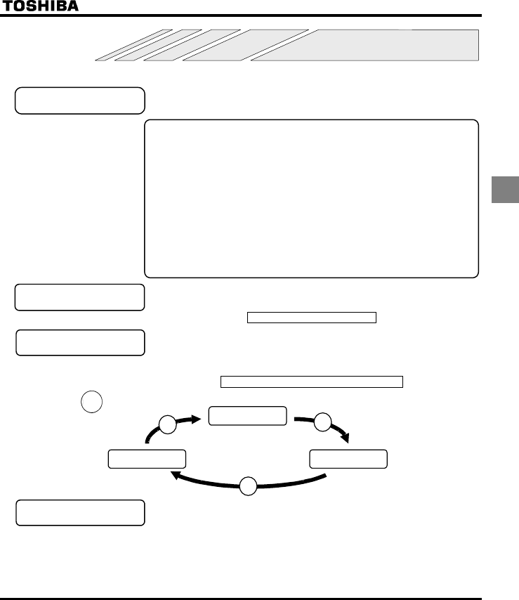
Pressing the key
will move the inverter through each of the modes.
Standard monitor
mode
Status monitor
mode
Setting monitor
mode
MODE
MODE
MODE
Panel jog mode : This mode allows you to jog the motor by controlling the
operation from the operation panel.
This mode is hidden by default.
To use the panel jog mode, set the parameter H to.
MODE
E6581160
28
4
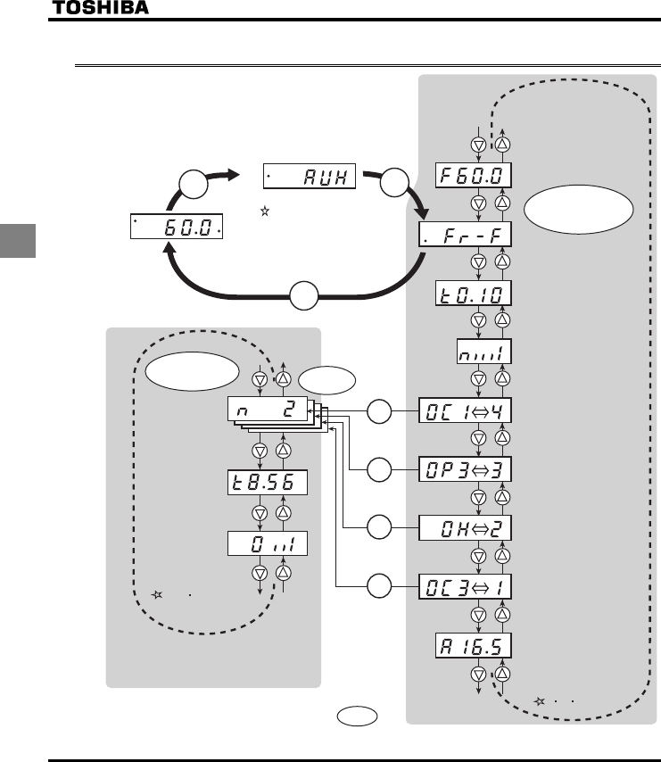
4.1 Flow of status monitor mode
Setting monitor mode
Standard monitor mode Display mode
Hz
PRG
MON
RUN
MODE
MODE MODE
10 kinds of data
Data of 4 times.
ENT
ENT
ENT
ENT
Past trip record detained monitor mode
Note: To return to the original display mode, press the MODE key.
Status monitor mode
28 kinds of data
Of the 10 kinds of data predetermined,
any data can be read out 4 times.
Data collected at the time of occurrence
of a trip is retained.
Up to 28 kinds of data can be read out.
During normal operation: Data is displayed in real time. (See Section 5.1.1)
In case of a trip: Data collected at the time of occurrence of a trip is retained.
Flow of monitor as following

E6581160
29
4
4.2 How to set parameters
The standard default parameters are programmed before the unit is shipped from the factory. Parameters can be
divided into 4 major categories. Select the parameter to be changed or to be searched and retrieved.
Basic parameters : The basic parameters that must be programmed
before the first use. (See 4.2.1)
Extended parameters : The parameters for detailed and special setting. (See
4.2.2)
User parameters
(automatic edit function)
: Indicates parameters that are different from the
standard default setting parameters. Use them to
check after setting and to change setting.
(Parameter title: I4W). (See 4.2.3)
: This parameter has the function of displaying, in
reverse chronological order, the five parameters that
were changed last. This function comes in very handy
when you adjust the inverter repeatedly using the
same parameter. (Parameter name: CWJ). (See
4.2.4)
* Adjustment range of parameters
JK: An attempt has been made to assign a value that is higher than the programmable range. Or, as
a result of changing other parameters, the programmed value of the parameter that is now
selected exceeds the upper limit.
NQ: An attempt has been made to assign a value that is lower than the programmable range. Or, as a
result of changing other parameters, the programmed value of the parameter that is now selected
exceeds the lower limit.
If the above alarm is flashing on and off, no setting can be done of values that are equal to or greater
than JK or equal to or lower than NQ.
History parameter
E6581160
30
4
4.2.1 How to set the basic parameters
All of the basic parameters can be set by the same step procedures.
Switches to the setting monitor mode.
* Parameters were
factory-set by default
before shipment.
* Select the parameter to
be changed from "Table
of parameters".
* If there is something
that you do not
understand during the
operation, press the
MODE key to return to
the indication.
* See 7.2 for basic
parameters.
Reads the programmed parameter
setting.
Saves the changed value of the
parameter setting.
Selects parameter to be changed.
Changes the parameter setting.
[Steps in key entry for basic parameters]
MODE
Steps in setting are as follows (example of changing the maximum frequency from 80Hz to 60Hz).
Key operated LED display Operation
Displays the operation frequency (operation stopped).
(When standard monitor display selection H= [Operation
frequency])
CWJ The first basic parameter “CWJ” (history function) is displayed.
HJ Press either the or key to select “HJ”.
Pressing the ENTER key reads the maximum frequency.
Press the key to change the maximum frequency to 60Hz.
⇔HJ Press the ENT key to save the maximum frequency. HJ and the
frequency are displayed alternately.
After this, →Displays the same
programmed
parameter.
→Switches to the
display in the
status monitor
mode.
→Displays names
of other
parameters.
MODE
MODE
E6581160
31
4
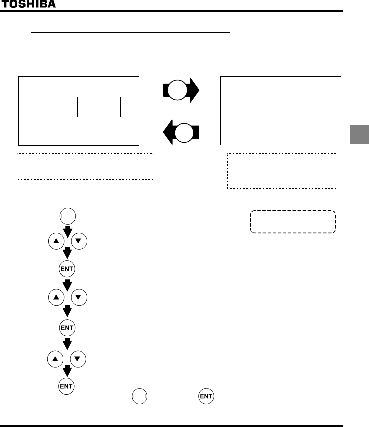
4.2.2 How to set extended parameters
The VF-S11 has extended parameters to allow you to make full use of its functions.
All extended parameters are expressed with H and three digits.
Basic parameters
H H~H
ENT
Press the MODE key once and use the VW key
to select H from the basic parameters.
Press the V key or the W key to
change the set value. Pressing
the ENTER key allows the reading
of parameter setting.
MODE
[Steps in key entry for extended parameters]
: switches to the setting monitor mode.(Displays CWJ)
: Selects the extended parameter whose setting needs to be changed.
: Changes the parameter setting.
Saves the changed value of the extended parameter setting.
Pressing the key instead of the key moves back to the previous status.
: Selects "H" from basic parameters.
: The first extended parameter “HK” (Low-speed signal output frequency) is displayed.
: Reads the programmed parameter setting.
MODE
MODE * See 7.3 for extended
parameters.
E6581160
32
4
QExample of parameter setting
Steps in setting are as follows
(Example of changing the dynamic braking selection H from 0 to 1.)
Key operated LED display Operation
.
Displays the operation frequency (operation stopped).
(When standard monitor display selection H= [Operation
frequency])
CWJ The first basic parameter “CWJ” (history function) is displayed.
H Press either the or the to change to the parameter group
H.
H Press the ENTER key to display the first extended parameter
H.
H Press the key to change to the dynamic braking selection H.
Pressing the ENTER key allows the reading of parameter setting.
Press the key to change the dynamic braking selection from to
.
⇔H Pressing the ENTER key alternately flashes on and off the parameter
and changed value and allows the save of those values.
If there is anything you do not understand during this operation, press the MODE key several times to
start over from the step of CWJ display.
For details on the function of each parameter, refer to the full version of English manual (E6581158).
4.2.3 Search and resetting of changed parameters (I4W)
Automatically searches for only those parameters that are programmed with values different from the
standard default setting and displays them in the user parameter group I4W. Parameter setting can also be
changed within this group.
Notes on operation
•If you reset a parameter to its factory default, the parameter will no longer appear in I4W.
•fO, f470-f473 are not appeared, if the value of these parameters are changed.
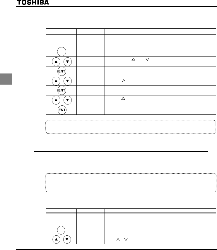
QHow to search and reprogram parameters
The operations of search and resetting of parameters are as follows.
Key operated LED display Operation
Displays the operation frequency (operation stopped).
(When standard monitor display selection H= [Operation
frequency])
CWJ The first basic parameter “CWJ” (history function) is displayed.
ITW Press or key to select I4W.
MODE
MODE
E6581160
33
4
Key operated LED display Operation
W Press the ENTER key to enable the user parameter automatic edit
function.
or
WH
(WT)
↓
CEE
Searches for parameters that are different in value from the standard
default setting and displays those parameters. Press the ENTER key
or the key to change the parameter displayed. (Pressing the key
moves the search in the reverse direction).
Press the ENTER key to display the set value.
Press the key and key to change set value.
⇔CEE
Press the ENTER key to save the changed value. The parameter
name and the programmed value will flash on and off alternately.
After the change has been saved, “W“ is displayed.
WH
(WT)
Use the same steps as those given above to display parameters that
you want to search for or change setting with the key and key.
ITW When IT. W appears again, the search is ended.
ITW
↓
HTH
↓
A search can be canceled by pressing the MODE key. Press the
MODE key once while the search is underway to return to the display
of parameter setting mode.
After that you can press the MODE key to return to the status
monitor mode or the standard monitor mode (display of operation
frequency).
If there is anything you do not understand during this operation, press the key several times to
start over from the step of auh display.
4.2.4 Searching for a history of changes, using the history
function (CWJ)
History function (CWJ):
Automatically searches for 5 latest parameters that are programmed with values different from the
standard default setting and displays them in the CWJ. Parameter setting can also be changed
within this group CWJ.
Notes on operation
•If no history information is stored, this parameter is skipped and the next parameter “CWK” is
displayed.
•JGCF and GPF are added respectively to the first and last parameters in a history of changes.
MODE
MODE
MODE
E6581160
34
4
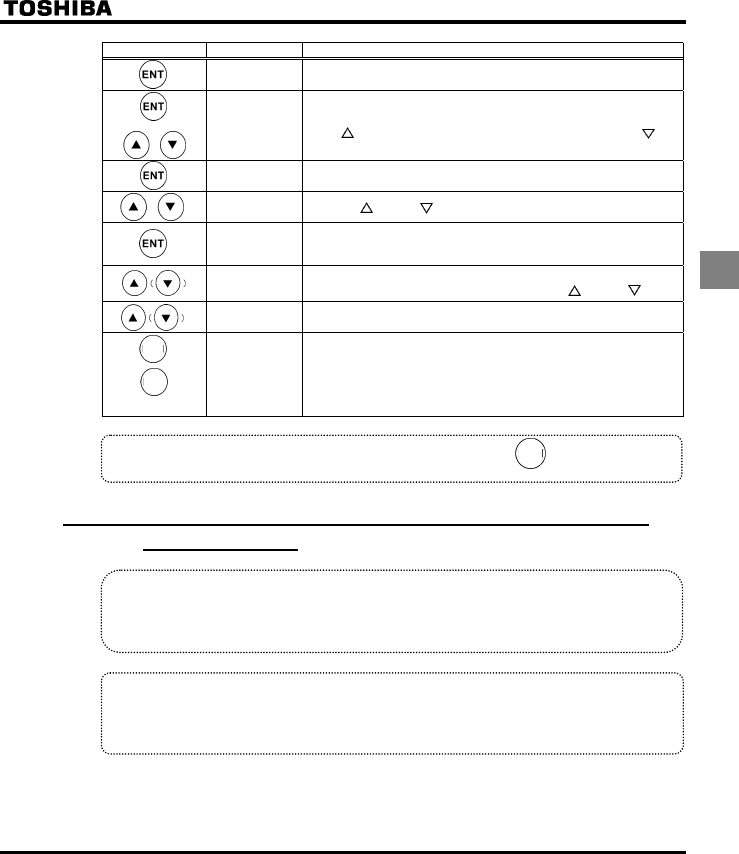
QHow to use the history function
Key operated LED display Operation
Displays the operation frequency (operation stopped).
(When standard monitor display selection H= [Operation
frequency])
CWJ The first basic parameter “CWJ” (history function) is displayed.
CEE The parameter that was set or changed last is displayed.
Press the ENTER key to display the set value.
Press the key and key to change set value.
⇔CEE Press the ENTER key to save the changed value. The parameter
name and the programmed value will flash on and off alternately.
**** Use the same steps as those given above to display parameters that
you want to search for or change setting with the key and key.
JGCF
(GPF)
JGCF: First historic record
GPF: Last historic record
Parameter
display
↓
CWJ
↓
HTH
↓
Press the MODE key to return to the parameter setting mode
“CWJ.”
After that you can press the MODE key to return to the status
monitor mode or the standard monitor mode (display of operation
frequency).
Note) Parameter f700 (Prohibition of change of parameter settings) is not displaied in this “auh”.
4.2.5 Parameters that cannot be changed while running
For safety reasons, the following parameters have been set up so that they cannot be reprogrammed while
the inverter is running. Stop operation (“0.0” or “off” is displayed) before changing parameter settings.
[Basic parameters]
CW, CW, CW, EOQF*, HOQF*, V[R, HJ, XN, XNX, RV
[Extended parameters]
H, H∼H, H∼H, H, H, H, H∼H, H,
H∼H, H, H∼H, H∼H, H, H, H, H,
H, H, H, H∼H
The setting of any parameter other than the above can be changed even during operation.
Keep in mind, however, that when the parameter H (prohibition of change of parameter settings) is set to
(prohibited), no parameters can be set or changed.
*Set H, cmod and fmod can be changed while the inverter is running.
MODE
MODE
MODE
MODE
E6581160
35
4
4.2.6 Returning all parameters to standard default setting
Setting the standard default setting parameter V[R=, all parameters can be returned to the those factory
default settings.
Note: For more details on the standard default setting parameter V[R, see 5.6.
Notes on operation
•We recommend that before this operation you write down on paper the values of those parameters,
because when setting V[R=, all parameters with changed values will be returned to standard
factory default setting.
•Note that HO, HOUN, H, f470-f473, H and H will not be reset to their
factory default settings.
QSteps for returning all parameters to standard default setting
Key operated LED display Operation
Displays the operation frequency (perform during operation stopped).
CWJ The first basic parameter “CWJ” (history function) is displayed.
V[R Press the key or the key to change to V[R.
Pressing the ENTER key displays the programmed parameters.
(V[R will always display "(zero)" on the right, the previous setting
on the left.)
Press the key or the key to change the set value.
To return to standard factory default setting, change to "".
KPKV Pressing the ENTER key displays "KPKV" while returning all
parameters to factory default setting.
The monitor returns to the display of setup parameters.
If there is anything you do not understand during this operation, press the key several times to
start over from the step of CWJ display.
4.2.7 How to save/load the user setting parameters
The current settings of all parameters can be stored (saved) in memory at a time by setting the standard
setting mode selection parameter V[p to 7. Also, all parameter settings stored in memory can be restored
(loaded) by setting parameter V[p to 8. This means that you can use this parameter (V[p=7 and 8) as
the parameter for your own initial settings (default settings).
MODE
MODE
E6581160
36
5
5. Monitoring the operation status
Refer to 4.1 about flow of monitor.
5.1 Status monitor mode
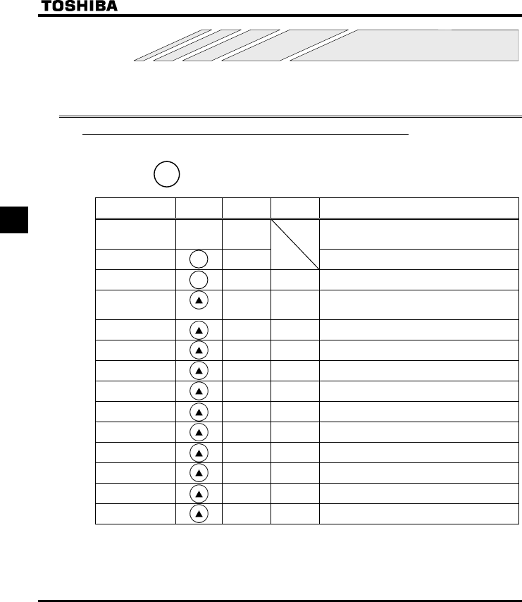
5.1.1 Status monitor under normal conditions
In this mode, you can monitor the operation status of the inverter.
To display the operation status during normal operation:
Press the key twice.
Setting procedure (eg. operation at 60Hz)
Item displayed Key
operated
LED
display
Communic
ation No. Description
.
The operation frequency is displayed (Operation at
60Hz). (When standard monitor display selection
H is set at 0 [operation frequency])
Parameter setting
mode CWJ The first basic parameter “CWJ” (history function)
is displayed.
Direction of
rotation HTH FE01 The direction of rotation is displayed.
(HTH: forward run, HTT: reverse run)
Operation
frequency
command
H FE02
The operation frequency command value (Hz/free
unit) is displayed.
Load current E FE03 The inverter output current (load current) (%/A) is
displayed.
Input voltage [ FE04 The inverter input (DC) voltage (%/V) is displayed.
Output voltage R FE05 The inverter output voltage (%/V) is displayed.
Torque SQ FE18 The torque (%) is displayed.
Torque current Y FE20 The torque current (%/A) is displayed.
Inverter load factor N FE27 The inverter load factor (%) is displayed.
PBR cumulative
load factor T FE25 The cumulative load factor of the braking resistor
(%) is displayed.
Input power k FE29 The inverter input power (kW) is displayed.
Output power J FE30 The inverter output power (kW) is displayed.
Operation
frequency Z FD00 The operation frequency (Hz/free unit) is
displayed.
(Continued overleaf)
Note 1
Note 2
Note 3
MO
MOMO
MODE
DEDE
DE
MO
MOMO
MODE
DEDE
DE
MODE
E6581160
37
5
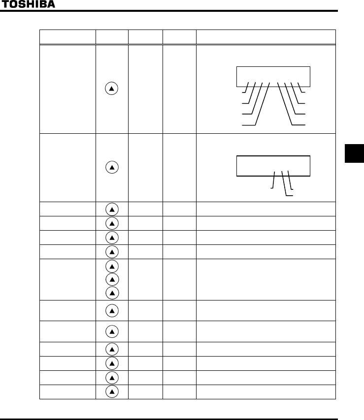
(Continued)
Item displayed Key
operated
LED
display
Communic
ation No. Description
Input terminal }}}ii}ii FE06
The ON/OFF status of each of the control signal
input terminals (F, R, RES, S1, S2, S3, VIB and
VIA) is displayed in bits.
ON:
OFF: _
Output terminal 0 }ii FE07
The ON/OFF status of each of the control signal
output terminals (RY, OUT and FL) is displayed in
bits.
ON:
OFF: _
CPU1 version X FE08 The version of the CPU1 is displayed.
CPU2 version XY FE73 The version of the CPU2 is displayed.
Memory version XG FE09 The version of the memory mounted is displayed.
PID feedback F FE22 The PID feedback value is displayed. (Hz / free
unit)
Frequency
command value
(PID-computed)
D FE15 The PID-computed frequency command value is
displayed. (Hz / free unit)
Integral input
power k FE76
The integrated amount of power (kWh) supplied to
the inverter is displayed.
(0.01=1kWh, 1.00=100kWh)
Integral output
power J FE77
The integrated amount of power (kWh) supplied
from the inverter is displayed.
(0.01=1kWh, 1.00=100kWh)
Rated current C FE70 The rated current of the inverter (A) is displayed.
Past trip 1 QE ⇔FE10 Past trip 1 (displayed alternately)
Past trip 2 QJ ⇔FE11 Past trip 2 (displayed alternately)
Past trip 3 QR ⇔FE12 Past trip 3 (displayed alternately)
(Continued overleaf)
0 }ii
RY-RC
FL
OUT-NO
Note 6
Note 6
Note 7
Note 7
Note 4
Note 5
}}}ii}ii
VIA
VIB
S3
S2
F
R
RES
S1
Note 7
E6581160
38
5
(Continued)
Item displayed Key
operated
LED
display
Communic
ation No. Description
Past trip 4 PGTT ⇔FE13 Past trip 4 (displayed alternately)
Parts replacement
alarm information m }}}i FE79
The ON/OFF status of each of the cooling fan,
circuit board capacitor, main circuit capacitor of
parts replacement alarm or cumulative operation
time are displayed in bits.
ON:
OFF: _
Cumulative
operation time V FE14 The cumulative operation time is displayed.
(0.01=1 hour, 1.00=100 hours)
Default display
mode The operation frequency is displayed (Operation at
60Hz).
MO
MOMO
MODE
DEDE
DE
Note 7
Note 8
Note 9
m }}}i
Cooling fan
Cumulative
operation time Control circuit board capacitor
Main circuit capacitor
E6581160
39
5
5.1.2 Display of detailed information on a past trip
Details on a past trip (of trips 1 to 4) can be displayed, as shown in the table below, by pressing the key
when the trip record is selected in the status monitor mode.
Unlike the "Display of detailed trip information at the occurrence of a trip" in 5.2.2, details on a past trip can be
displayed, even after the inverter is turned off or reset.
Item displayed Key
operated LED display Description
Past trip 1 QE
⇔Past trip 1 (displayed alternately)
Continuous trips P The number of time the same trip occurred in succession is
displayed. (Unit: times)
Operation
frequency Z6 The operation frequency when the trip occurred is
displayed.
Direction of
rotation HTH The direction of rotation when the trip occurred is displayed.
(HTH: Forward run, HTT: Reverse run)
Operation
frequency
command
H
The operation command value when the trip occurred is
displayed.
Load current E The inverter output current when the trip occurred is
displayed. (%/A)
Input voltage [ The inverter input voltage (DC) when the trip occurred is
displayed. (%/V).
Output voltage R The inverter output voltage when the trip occurred is
displayed. (%/V)
Input terminal }}}ii}ii
The ON/OFF statuses of the control input terminals (F, R,
RES, S1, S2, S3, VIB and VIA) are displayed in bits.
ON:
OFF: _
Output terminal 0 }ii
The ON/OFF statuses of the control output terminals (RY,
OUT and FL) are displayed in bits.
ON:
OFF: _
Cumulative
operation time V
The cumulative operation time when the trip occurred is
displayed.
(0.01=1 hour, 1.00=100 hours)
Past trip 1 QE
⇔ Press this key to return to past trip 1.
0 }ii
RY-RC
FL
OUT-NO
MO
MOMO
MODE
DEDE
DE
}}}ii}ii
VIA
VIB
S3
S2
RES
S1
R
F
Note 1
Note 3
Note 4
Note 5
Note 9
Note 11
Note 2
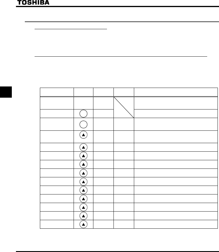
E6581160
40
5
5.2 Display of trip information
5.2.1 Trip code display
If the inverter trips, an error code is displayed to suggest the cause. Since trip records are retained, information
on each trip can be displayed anytime in the status monitor mode.
For the kinds of causes that can be indicated in the event of a trip, see section 9.1.
5.2.2 Display of trip information at the occurrence of a trip
At the occurrence of a trip, the same information as that displayed in the mode described in 5.1.1, "Status monitor
under normal conditions," can be displayed, as shown in the table below, if the inverter is not turned off or reset.
To display trip information after turning off or resetting the inverter, follow the steps described in 5.1.2, "Display of
detailed information on a past trip."
Example of call-up of trip information
Item displayed Key
operated
LED
display
Communic
ation No. Description
Cause of trip QR
Status monitor mode (The code blinks if a trip
occurs.)
The motor coasts and comes to a stop (coast stop).
Parameter setting
mode CWJ The first basic parameter “CWJ” (history function)
is displayed.
Direction of
rotation HT-HFE01
The direction of rotation at the occurence of a trip
is displayed. (HTH: forward run, HTT:
reverser run).
Operation
frequency
command
H FE02
The operation frequency command value (Hz/free
unit) at the occurrence of a trip is displayed.
Load current E FE03 The output power of the inverter at the occurrence
of a trip (%/A) is displayed.
Input voltage [ FE04 The inverter input (DC) voltage (%/V) at the
occurrence of a trip is displayed.
Output voltage R FE05 The output voltage of the inverter at the
occurrence of a trip (%/V) is displayed.
Torque SQ FE18 The torque at the occurrence of a trip (%) is
displayed.
Torque current Y FE20 The torque current (%/A) at the occurrence of a
trip is displayed.
Inverter load factor N FE27 The inverter load factor (%) at the occurrence of a
trip is displayed.
PBR cumulative
load factor T FE25 The cumulative load factor (%) of the resistor at
the occurrence of a trip is displayed.
Input power k FE29 The inverter input power (kW) at the occurrence of
a trip is displayed.
Output power J FE30 The inverter output power (kW) at the occurrence
of a trip is displayed.
Operation
frequency Z FE00 The inverter output frequency (Hz/free unit) at the
occurrence of a trip is displayed.
(Continued overleaf)
MO
MOMO
MODE
DEDE
DE
MO
MOMO
MODE
DEDE
DE
Note 3
Note 2
Note 1
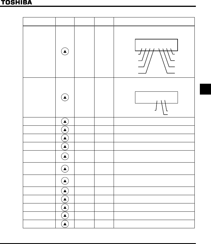
E6581160
41
5
(Continued)
Item displayed Key
operated
LED
display
Communic
ation No. Description
Input terminal }}}ii}ii FE06
The ON/OFF statuses of the control input
terminals (F, R, RES, S1, S2, S3, VIB and VIA) are
displayed in bits.
ON:
OFF: _
Output terminal 0 }ii FE07
The ON/OFF status of each of the control signal
output terminals (RY, OUT and FL) at the
occurrence of a trip is displayed in bits.
ON:
OFF: _
CPU1 version X FE08 The version of the CPU1 is displayed.
CPU2 version XY FE73 The version of the CPU2 is displayed.
Memory version XG FE09 The version of the memory mounted is displayed.
PID feedback F FE22 The PID feedback value at the occurrence of a trip
is displayed. (Hz / free unit)
Frequency
command value
(PID-computed)
D FE15
The PID-computed frequency command value at
the occurrence of a trip is displayed. (Hz / free
unit)
Integral input
power k FE76
The integrated amount of power (kWh) supplied to
the inverter is displayed.
(0.01=1kWh, 1.00=100kWh)
Integral output
power J FE77
The integrated amount of power (kWh) supplied
from the inverter is displayed.
(0.01=1kWh, 1.00=100kWh)
Rated current C FE70 The inverter rated current (A) at the occurrence of
a trip is displayed.
Past trip 1 QR ⇔FE10 Past trip 1 (displayed alternately)
Past trip 2 QJ ⇔FE11 Past trip 2 (displayed alternately)
Past trip 3 QR ⇔FE12 Past trip 3 (displayed alternately)
Past trip 4 PGTT ⇔FE13 Past trip 4 (displayed alternately)
(Continued overleaf)
0 }ii
RY-RC
FL
OUT-NO
}}}ii}ii
VIA
VIB
S3
S2
RES
S1
R
F
Note 4
Note 5
Note 7
Note 7
Note 7
Note 7
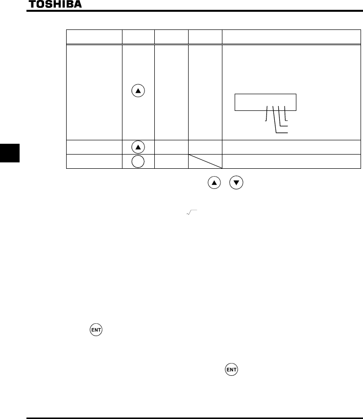
E6581160
42
5
(Continued)
Item displayed Key
operated
LED
display
Communic
ation No. Description
Parts replacement
alarm information m }}}i FE79
The ON/OFF status of each of the cooling fan,
circuit board capacitor, main circuit capacitor of
parts replacement alarm or cumulative operation
time are displayed in bits.
ON:
OFF: _
Cumulative
operation time V FE14 The cumulative operation time is displayed.
(0.01=1 hour, 1.00=100 hours)
Default display
mode QR The cause of the trip is displayed.
Note 1: Items displayed can be changed by pressing or key in the each monitor mode.
Note 2: You can switch between % and A (ampere)/V (volt), using the parameter H (current/voltage unit
selection).
Note 3: The input (DC) voltage displayed is 1 2 times as large as the rectified d.c. input voltage.
Note 4: The number of bars displayed varies depending on the setting of H (analog input/logic input
function selection). The bar representing VIA or VIB is displayed only when the logic input function is
assigned to the VIA or VIB terminal, respectively.
If H = 0: Neither the bar representing VIA nor the bar representing VIB is displayed.
If H = 1 or 2: The bar representing VIA is not displayed.
The bar representing VIB is displayed.
If H = 3 or 4: Both the bar representing VIA and VIB are displayed.
Note 5: The number of bars displayed varies depending on the setting of H (logic output/pulse train output
selection). The bar representing the OUT-NO terminal is displayed only when logic output function is
assigned to it.
If H = 0: The bar representing OUT-NO is displayed.
If H = 1: The bar representing OUT-NO is not displayed.
Note 6: The integrated amounts of input and output power will be reset to zero, if you press and hold down the
key for 3 seconds or more when power is off or when the input terminal function CKWH (input
terminal function: 51) is turned on or displayed.
Note 7: Past trip records are displayed in the following sequence: 1 (latest trip record) ⇔2⇔3⇔4 (oldest trip
record). If no trip occurred in the past, the message “PGTT” will be displayed. Details on past trip
record 1, 2, 3 or 4 can be displayed by pressing the key when past trip 1, 2, 3 or 4 is displayed. For
more information, see 5.1.2.
Note 8: Parts replacement alarm is displayed based on the value calculated from the annual average ambient
temperature, the ON time of the inverter, the operating time of the motor and the output current ( load
factor) specified using H. Use this alarm as a guide only, since it is based on a rough estimation.
m }}}i
Cooling fan
Cumulative
operation time Control circuit board capacitor
Main circuit capacitor
Note 8
Note 9
MO
MOMO
MODE
DEDE
DE

E6581160
43
5
Note 9: The cumulative operation time increments only when the machine is in operation.
Note 10: At the occurrence of a trip, maximum values are not always recorded and displayed for reasons of
detecting time.
Note 11: If there is no trip record, nerr is displayed.
✩
✩✩
✩Of the items displayed on the monitor, the reference values of items expressed in percent are listed below.
•Load current: The current monitored is displayed. The reference value (100% value) is
the rated output current indicated on the nameplate. That is, it
corresponds to the rated current at the time when the PWM carrier
frequency (f300) is 4kHz or less. The unit can be switched to A
(amperes).
•Input voltage: The voltage displayed is the voltage determined by converting the voltage
measured in the DC section into an AC voltage. The reference value
(100% value) is 200 volts for 240V models, 400 volts for 500V models or
575 volts for 600V models. The unit can be switched to V (volts).
•Torque: The torque generated by the drive motor is displayed. The reference value
(100% value) is the rated torque of the motor.
•Torque current: The current required to generate torque is calculated from the load current
by vector operations. The value thus calculated is displayed. The
reference value (100% value) is the value at the time when the load
current is 100%.
•Load factor of inverter: Depending on the PWM carrier frequency (f300) setting and so on, the
actual rated current may become smaller than the rated output current
indicated on the nameplate. With the actual rated current at that time (after
a reduction) as 100%, the proportion of the load current to the rated
current is indicated in percent. The load factor is also used to calculate the
conditions for overload trip (QN).
•PBR cumulative load factor: The load factor of the braking resistor that may come up to the level at
which an overload trip (QNT) occurs is indicated in percent. An overload
trip occurs when it reaches 100%.

E6581160
44
6
6. Measures to satisfy the standards
6.1 How to cope with the CE directive
In Europe, the EMC directive and the low-voltage directive, which took effect in 1996 and 1997, respectively,
make it obligatory to put the CE mark on every applicable product to prove that it complies with the directives.
Inverters do not work alone but are designed to be installed in a control panel and always used in combination
with other machines or systems which control them, so they themselves are not considered to be subject to the
EMC directive. However, the CE mark must be put on all inverters because they are subject to the low-voltage
directive.
The CE mark must be put on all machines and systems with built-in inverters because such machines and
systems are subject to the above directives. It is the responsibility of the manufacturers of such final products to
put the CE mark on each one. If they are "final" products, they might also be subject to machine-related
directives.
It is the responsibility of the manufacturers of such final products to put the CE mark on each one. In order to
make machines and systems with built-in inverters compliant with the EMC directive and the low-voltage
directive, this section explains how to install inverters and what measures should be taken to satisfy the EMC
directive.
We have tested representative models with them installed as described later in this manual to check for
conformity with the EMC directive. However, we cannot check all inverters for conformity because whether or not
they conform to the EMC direction depends on how they are installed and connected. In other words, the
application of the EMC directive varies depending on the composition of the control panel with a built-in
inverter(s), the relationship with other built-in electrical components, the wiring condition, the layout condition, and
so on. Therefore, please verify yourself whether your machine or system conforms to the EMC directive.
6.1.1 About the EMC directive
Inverters themselves are not subject to approval for CE marking.
The CE mark must be put on every final product that includes an inverter(s) and a motor(s). The VF-S11 series of
inverters complies with the EMC directive if an EMI filter recommended by Toshiba is connected to it and wiring is
carried out correctly.
QEMC directive 89/336/EEC
The EMC standards are broadly divided into two categories; immunity- and emission-related standards, each of
which is further categorized according to the operating environment of each individual machine. Since inverters
are intended for use with industrial systems under industrial environments, they fall within the EMC categories
listed in Table 1 below. The tests required for machines and systems as final products are almost the same as
those required for inverters.
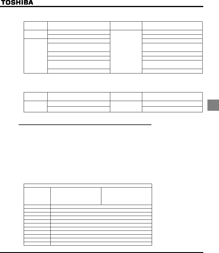
E6581160
45
6
Table 1 EMC standards
Category Subcategory Product
standards Test standard and level
Radiation noise EN55011 Class A Group 1
Emission Transmission noise EN55011 Class A Group 1
Static discharge IEC61000-4-2
Radioactive radio-frequency
magnetic contactor field
IEC61000-4-3
First transient burst IEC61000-4-4
Lightning surge IEC61000-4-5
Radio-frequency
induction/transmission interference
IEC61000-4-6
Immunity
Voltage dip/Interruption of power
IEC 61800-3
IEC61000-4-11
Emission standards other than the above are applied to inverters when used in a commercial environment but not
an industrial environment.
Category Subcategory Product
standards Test standard and level
Radiation noise EN55011 Class B Group 1
Emission Transmission noise IEC 61800-3 EN55011 Class B Group 1
6.1.2 Measures to satisfy the EMC directive
This subsection explains what measures must be taken to satisfy the EMC directive.
(1) Insert a recommended EMI filter (Table 2) on the input side of the inverter to reduce and transmission noise
and radiation noise from input cables.
In the combinations listed in Table 2, Inverters are tested in these combination to see if they comply with
transmission noise standards. For inverters used in Japan, it is recommended to use the NF series of noise
filters.
Table 2 lists noise filters recommended for the inverters.
Table 2 Combinations of inverter and EMI filter
Three-phase 240V class
Combination of inverter and filter
Inverter Transmission noise
EN55011 Class A Group 1
Applicable filters
(Length of motor connecting cable:
Max. 5 m)
Transmission noise
EN55011 Class B Group 1
Applicable filters
(Length of motor connecting cable:
Max. 1 m)
VFS11-2002PM EMFS11-2007AZ
VFS11-2004PM EMFS11-2007AZ
VFS11-2005PM EMFS11-2007AZ
VFS11-2007PM EMFS11-2007AZ
VFS11-2015PM EMFS11-4015BZ
VFS11-2022PM EMFS11-4015BZ
VFS11-2037PM EMFS11-4025CZ
VFS11-2055PM EMFS11-4047DZ
VFS11-2075PM EMFS11-4047DZ
VFS11-2110PM EMFS11-2083EZ
VFS11-2150PM EMFS11-2083EZ
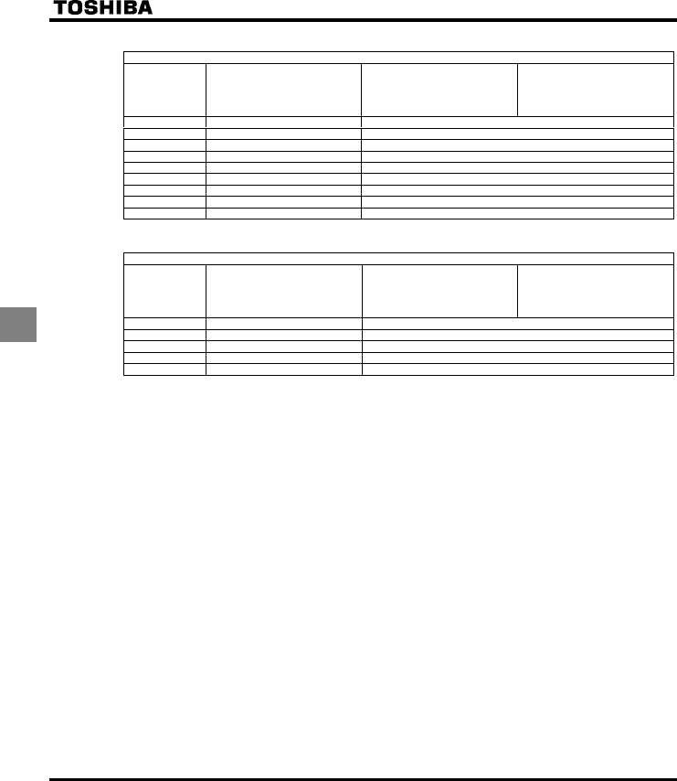
E6581160
46
6
Three-phase 500V class
Combination of inverter and filter
Inverter Transmission noise
EN55011 Class A Group 1
Applicable filters
(Length of motor connecting cable:
Max. 5 m)
Transmission noise
EN55011 Class B Group 1
Applicable filters
(Length of motor connecting cable:
Max. 20 m)
Transmission noise
EN55011 Class A Group 1
Applicable filters
(Length of motor connecting cable:
Max. 50 m)
VFS11-4004PL With a built-in filter EMFS11-4015BZ
VFS11-4007PL With a built-in filter EMFS11-4015BZ
VFS11-4015PL With a built-in filter EMFS11-4015BZ
VFS11-4022PL With a built-in filter EMFS11-4025CZ
VFS11-4037PL With a built-in filter EMFS11-4025CZ
VFS11-4055PL With a built-in filter EMFS11-4047DZ
VFS11-4075PL With a built-in filter EMFS11-4047DZ
VFS11-4110PL With a built-in filter EMFS11-4049EZ
VFS11-4150PL With a built-in filter EMFS11-4049EZ
Single-phase 240V class
Combination of inverter and filter
Inverter Transmission noise
EN55011 Class A Group 1
Applicable filters
(Length of motor connecting cable:
Max. 5 m)
Transmission noise
EN55011 Class B Group 1
Applicable filters
(Length of motor connecting cable:
Max. 20 m)
Transmission noise
EN55011 Class A Group 1
Applicable filters
(Length of motor connecting cable:
Max. 50 m)
VFS11S-2002PL With a built-in filter EMFS11S-2009AZ
VFS11S-2004PL With a built-in filter EMFS11S-2009AZ
VFS11S-2007PL With a built-in filter EMFS11S-2009AZ
VFS11S-2015PL With a built-in filter EMFS11S-2016BZ
VFS11S-2022PL With a built-in filter EMFS11S-2022CZ
Note : For 600V models compliant with EU standards, contact your nearest Toshiba inverter distributor.
(2) Use shielded power cables, such as inverter output cables, and shielded control cables. Route the cables
and wires so as to minimize their lengths. Keep a distance between the power cable and the control cable
and between the input and output wires of the power cable. Do not route them in parallel or bind them
together, instead cross at right angle.
(3) Install the inverter and the filter on the same metal plate. It is more effective in limiting the radiation noise to
install the inverter in a sealed steel cabinet. Using wires as thick and short as possible, earth the metal plate
and the control panel securely with a distance kept between the earth cable and the power cable.
(4) Route the EMI filter input and output wires apart from each other.
(5) To suppress radiation noise from cables, ground all shielded cables through a noise cut plate.
It is effective to earth shielded cables in the vicinity of the inverter, cabinet and filter (within a radius of 10cm
from each of them). Inserting a ferrite core in a shielded cable is even more effective in limiting the radiation
noise.
(6) To further limit the radiation noise, insert a zero-phase reactor in the inverter output line and insert ferrite
cores in the earth cables of the metal plate and cabinet.
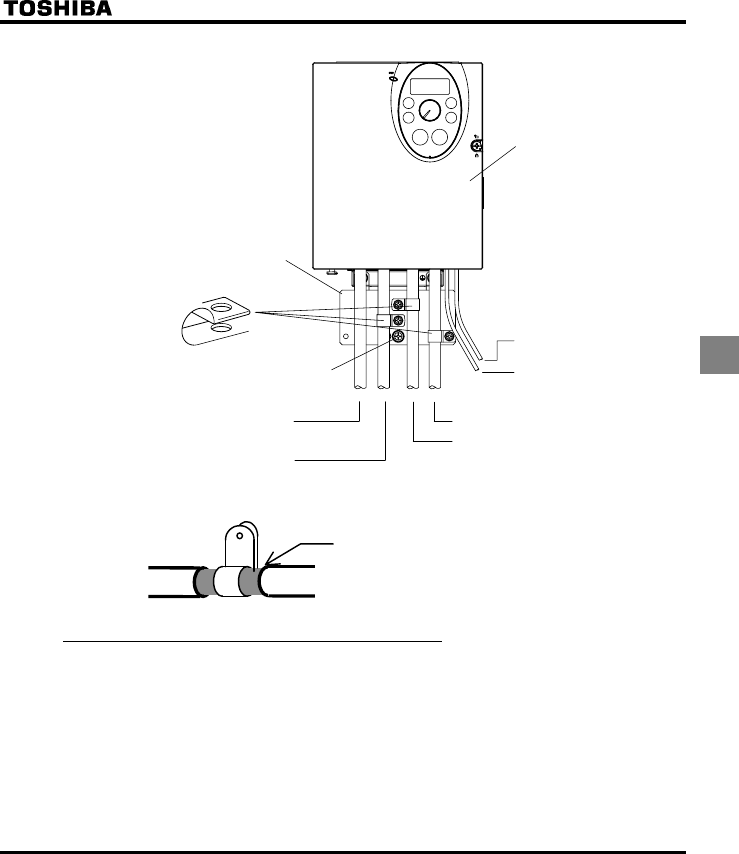
E6581160
47
6
[Example of wiring]
Control wiring (Shielded cables)
Motor wiring (Shielded cables)
Braking resistor wiring (Shielded cables)
Power supply wiring
FL relay wiring
VF-S11
To relay
Grounding terminal screw
(Note 1)
EMC plate
Note 1: Strip and earth the shielded cable, following the example shown in Fig.
Strip the cable and fix it to the metal plate by means
of a metal saddle for electrical work or equivalent.
Shielded cable
6.1.3 About the low-voltage directive
The low-voltage directive provides for the safety of machines and systems. All Toshiba inverters are CE-marked
in accordance with the standard EN 50178 specified by the low-voltage directive, and can therefore be installed in
machines or systems and imported without problem to European countries.
Applicable standard: EN50178
Electronic equipment for use in power installations
Electronic equipment for use in power installations
Pollution level: 2 (5.2.15.2)
Overvoltage category: 3
240V class - 3.0mm (5.2.16.1)
500V class - 5.5mm (5.2.16.1)

E6581160
48
6
EN 50178 applies to electrical equipment intended specially for use in power installations, and sets out the
conditions to be observed for electric shock prevention when designing, testing, manufacturing and installing
electronic equipment for use in power installations.
6.1.4 Measures to satisfy the low-voltage directive
When incorporating the inverter into a machine or system, it is necessary to take the following measures so that
the inverter satisfies the low-voltage directive.
(1) Install the inverter in a cabinet and ground the inverter enclosure. When doing maintenance, be extremely
careful not to put your fingers into the inverter through a wiring hole and touch a charged part, which may
occur depending on the model and capacity of the inverter used.
(2) Do not connect two or more wires to the main circuit earth terminal of the inverter. If necessary, install an
additional earth terminal on the metal plate on which the inverter is installed and connect another cable to it.
Or install the EMC plate (attached as standard) and another cable connect to earth terminal on the EMC
plate. Refer to the table 10.1 for earth cable sizes.
(3) Install a non-fuse circuit breaker or a fuse on the input side of the inverter.
6.2 Compliance with UL Standard and CSA Standard
The VF-S11 models, that conform to the UL Standard and CSA Standard have the UL/CSA mark on the
nameplate.
6.2.1 Compliance with Installation
The VF-S11 inverter must be installed in a panel, and used within the ambient temperature specification. (See
section 1.4.4)
6.2.2 Compliance with Connection
Use the UL conformed cables (Rating 75 °C or more) to the main circuit terminals (R/L1, S/L2, T/L3, U/T1, V/T2,
W/T3, PA/+, PB, PC/-, PO).
Refer to the table of next page about wire sizes.
6.2.3 Compliance with Peripheral devices
Use the UL listed fuses at connecting to power supply.
Short circuit test is performed under the condition of the power supply short-circuit currents in below.
These interrupting capacities and fuse rating currents depend on the applicable motor capacities.
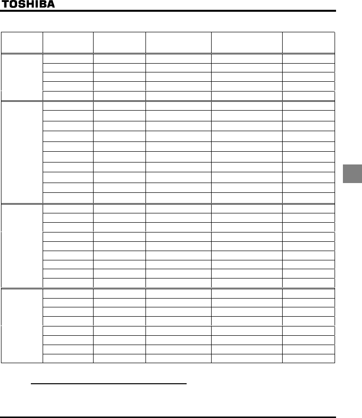
E6581160
49
6
QAIC, Fuse and Wire sizes
Voltage
class
Capacity of
applicable motor
(kW)
Inverter model AIC (A)
(Interrupting capacity)
Fuse class and current
(A)
Wire sizes of
power circuit
0.2 VFS11S-2002PL AIC 1000A CC/J 6A max. AWG 14
0.4 VFS11S-2004PL AIC 1000A CC/J 10A max. AWG 14
0.75 VFS11S-2007PL AIC 1000A CC/J 15A max. AWG 14
1.5 VFS11S-2015PL AIC 1000A CC/J 20A max. AWG 12
Single-phase
240V class
2.2 VFS11S-2022PL AIC 1000A CC/J 30A max. AWG 10
0.4 VFS11-2004PM AIC 5000A CC/J 6A max. AWG 14
0.55 VFS11-2005PM AIC 5000A CC/J 10A max. AWG 14
0.75 VFS11-2007PM AIC 5000A CC/J 10A max. AWG 14
1.5 VFS11-2015PM AIC 5000A CC/J 15A max. AWG 14
2.2 VFS11-2022PM AIC 5000A CC/J 20A max. AWG 12
4.0 VFS11-2037PM AIC 5000A J 35A max. AWG 10
5.5 VFS11-2055PM AIC 22000A J 50A max. AWG 8
7.5 VFS11-2075PM AIC 22000A J 60A max. AWG 6
11 VFS11-2110PM AIC 22000A J 80A max. AWG 4
Three-phase
240V class
15 VFS11-2150PM AIC 22000A J 110A max. AWG 6x2
0.4 VFS11-4004PL AIC 5000A CC/J 3A max. AWG 14
0.75 VFS11-4007PL AIC 5000A CC/J 6A max. AWG 14
1.5 VFS11-4015PL AIC 5000A CC/J 10A max. AWG 14
2.2 VFS11-4022PL AIC 5000A CC/J 15A max. AWG 14
4.0 VFS11-4037PL AIC 5000A CC/J 20A max. AWG 12
5.5 VFS11-4055PL AIC 22000A CC/J 30A max. AWG 10
7.5 VFS11-4075PL AIC 22000A J 35A max. AWG 8
11 VFS11-4110PL AIC 22000A J 50A max. AWG 8
Three-phase
500V class
15 VFS11-4150PL AIC 22000A J 70A max. AWG 6
0.75 VFS11-6007P AIC 5000A CC/J 6A max. AWG 14
1.5 VFS11-6015P AIC 5000A CC/J 6A max. AWG 14
2.2 VFS11-6022P AIC 5000A CC/J 10A max. AWG 14
4.0 VFS11-6037P AIC 5000A CC/J 15A max. AWG 14
5.5 VFS11-6055P AIC 22000A CC/J 20A max. AWG 10
7.5 VFS11-6075P AIC 22000A CC/J 25A max. AWG 10
11 VFS11-6110P AIC 22000A J 30A max. AWG 8
Three-phase
600V class
15 VFS11-6150P AIC 22000A J 45A max. AWG 8
6.2.4 Motor thermal protection
Selects the electronic thermal protection characteristics that fit with the ratings and characteristics of the motor. In
case of multi motor operation with one inverter, thermal relay should be connected to each motor.
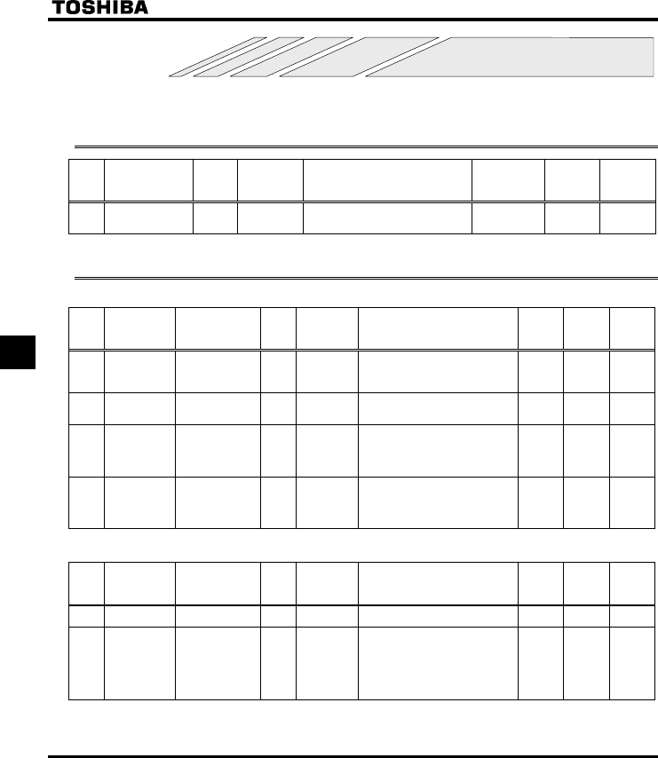
E6581160
50
7
7. Table of parameters and data
For details on the function of each parameter, refer to the full version of English manual (E6581158).
7.1 User parameters
Title Function Unit
Minimum
setting unit
Panel/Comm
unication
Adjustment range Default setting User
setting
Reference
E6581158
HE Operation
frequency of
operation panel
Hz 0.1/0.01 NN-WN 0.0 3.2
7.2 Basic parameters
•Four navigation functions
Title Communication
No. Function Unit
Minimum
setting unit
Panel/Commun
ication
Adjustment range Default
setting
User
setting
Reference
E6581158
CWJ - History function - - Displays parameters in groups of five
in the reverse order to that in which
their settings were changed.
* (Possible to edit)
- 4.1.4
CW 0000 Automatic
acceleration/
deceleration
- - 0: Disabled (manual)
1: Automatic
2: Automatic (only at acceleration)
0 5.1.1
CW 0001 Torque boost
setting macro
function
- - 0: Disabled
1: Automatic torque boost + auto-
tuning
2: Vector control + auto-tuning
3: Energy saving + auto-tuning
05.2
CW 0040 Parameter setting
macro function
- - 0: Disabled
1: Coast stop
2: 3-wire operation
3: External input UP/DOWN setting
4: 4-20 mA current input operation
05.3
•Basic parameters
Title Communication
No. Function Unit
Minimum
setting unit
Panel/Commun
ication
Adjustment range Default
setting
User
setting
Reference
E6581158
EOQF 0003 Command mode
selection
- - 0: Terminal board
1: Operation panel
15.4
7.2
HOQF 0004 Frequency setting
mode selection 1
- - 0: Built-in potentiometer
1: VIA
2: VIB
3: Operation panel
4: Serial communication
5: UP/DOWN from external contact
6: VIA + VIB (Override)
05.4
6.5.1
7.1

E6581160
51
7
Title Communication
No. Function Unit
Minimum
setting unit
Panel/Commun
ication
Adjustment range Default
setting
User
setting
Reference
E6581158
HOUN 0005 Meter selection - - 0: Output frequency
1: Output current
2: Set frequency
3: DC voltage
4: Output voltage command value
5: Input power
6: Output power
7: Torque
8: Torque current
9: Motor cumulative load factor
10: Inverter cumulative load factor
11: PBR (braking reactor) cumulative
load factor
12: Frequency setting value (after
PID)
13: VIA Input value
14: VIB Input value
15: Fixed output 1 (Output current:
100%)
16: Fixed output 2 (Output current:
50%)
17: Fixed output 3 (Other than the
output current: 100%)
18: Serial communication data
19: For adjustments (HO set value is
displayed.)
05.5
HO 0006 Meter adjustment - - - - 5.5
V[R 0007 Default setting - - 0: -
1: 50Hz default setting
2: 60Hz default setting
3: Default setting (Initialization)
4: Trip record clear
5: Cumulative operation time clear
6: Initialization of type information
7: Save user-setting parameters
8. Load user-setting parameters
9. Cumulative fan operation time
record clears
0 4.2.6
4.2.7
5.6
HT 0008 Forward/reverse
run selection
(Operation panel)
- - 0: Forward run
1: Reverse run
2: Forward run (F/R switching
possible)
3: Reverse run (F/R switching
possible)
05.7
CEE 0009 Acceleration time
1
S 0.1/0.1 0.0-3200 10.0 5.1.2
FGE 0010 Deceleration time
1
S 0.1/0.1 0.0-3200 10.0 5.1.2
HJ 0011 Maximum
frequency
Hz 0.1/0.01 30.0-500.0 80.0 5.8
WN 0012 Upper limit
frequency
Hz 0.1/0.01 0.5- HJ 50.0 (WP)
60.0
(WN, AN)
5.9
NN 0013 Lower limit
frequency
Hz 0.1/0.01 0.0- WN 0.0 5.9
XN 0014 Base frequency 1 Hz 0.1/0.01 25-500.0 50.0 (WP)
60.0
(WN, AN)
5.10
XNX 0409 Base frequency
voltage 1
V 1/0.1 50-330 (240V class)
50-660 (500/600V class)
*3 5.10
6.13.6
*3 : 230 (240V class), 460 (500V class), 575V (600V class)
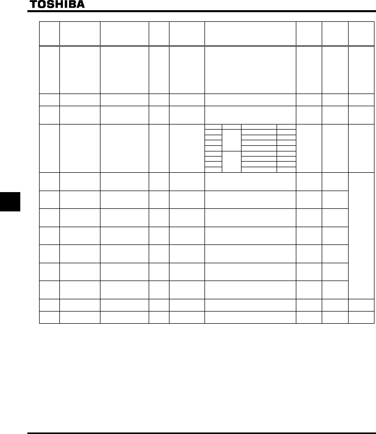
E6581160
52
7
Title Communication
No. Function Unit
Minimum
setting unit
Panel/Commun
ication
Adjustment range Default
setting
User
setting
Reference
E6581158
RV 0015 V/F control mode
selection
- - 0: V/F constant
1: Variable torque
2: Automatic torque boost control
3: Vector control
4: Energy-saving
5: Dynamic energy-saving
(for fans and pumps)
6: PM motor control
25.11
XD 0016 Torque boost
value 1
% 0.1/0.1 0.0-30.0 * 1 5.12
VJT 0600 Motor electronic-
thermal protection
level 1
%
(A)
1/1 10-100 100 5.13
6.19.1
Setting Overload protection OL stall
0{×
1{{
2××
3
Standard
motor
×{
4{×
5{{
6××
QNO 0017 Electronic-thermal
protection
characteristic
selection *2
--
7
VF motor
×{
05.13
UT 0018 Preset-speed
operation
frequency 1
Hz 0.1/0.01 NN-WN 0.0
UT 0019 Preset-speed
operation
frequency 2
Hz 0.1/0.01 NN-WN 0.0
UT 0020 Preset-speed
operation
frequency 3
Hz 0.1/0.01 NN-WN 0.0
UT 0021 Preset-speed
operation
frequency 4
Hz 0.1/0.01 NN-WN 0.0
UT 0022 Preset-speed
operation
frequency 5
Hz 0.1/0.01 NN-WN 0.0
UT 0023 Preset-speed
operation
frequency 6
Hz 0.1/0.01 NN-WN 0.0
UT 0024 Preset-speed
operation
frequency 7
Hz 0.1/0.01 NN-WN 0.0
5.14
H - Extended
parameters
- - - - - 4.1.2
ITW - Automatic edit
function
- - - - - 4.1.3
*1 : Default values vary depending on the capacity. See the table of the page 64.
*2 : { : valid, × : invalid
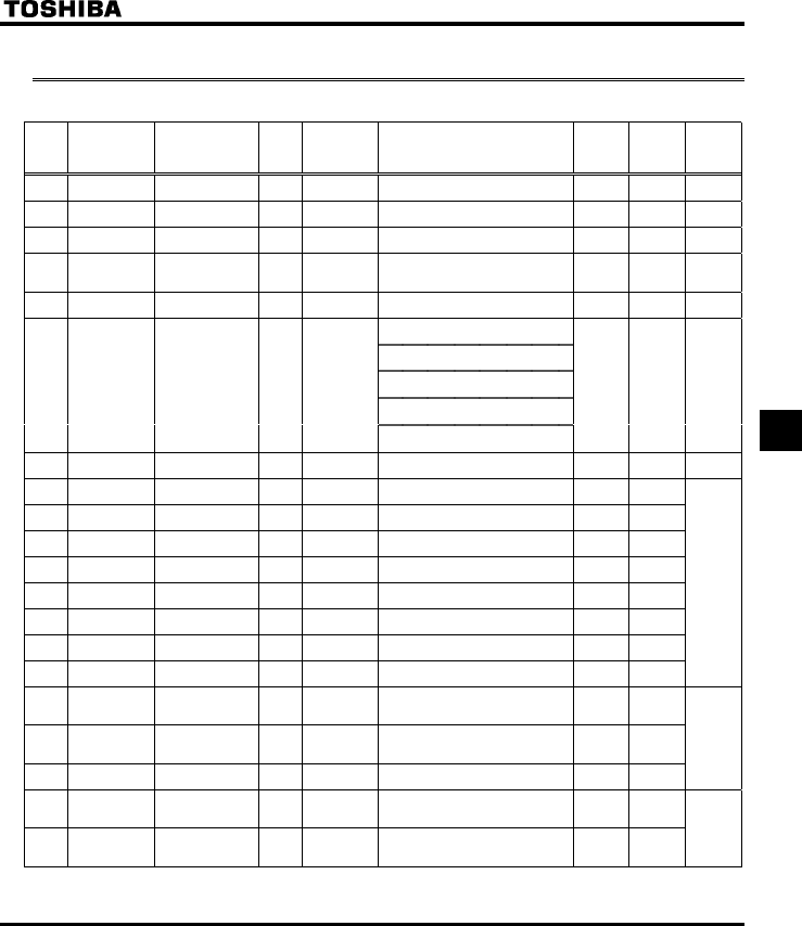
E6581160
53
7
7.3 Extended parameters
•Input/output parameters 1
Title Communication
No. Function Unit
Minimum
setting unit
Panel/Commun
ication
Adjustment range Default
setting
User
setting
Reference
E6581158
H 0100 Low-speed signal
output frequency
Hz 0.1/0.01 0.0-HJ 0.0 6.1.1
H 0101 Speed reach
setting frequency
Hz 0.1/0.01 0.0-HJ 0.0 6.1.3
H 0102 Speed reach
detection band
Hz 0.1/0.01 0.0-HJ 2.5 6.1.2
H 0105 Priority selection
(Both F-CC and
R-CC are ON)
--
0: Reverse
1: Slowdown Stop
1 6.2.1
H 0108 Always active
function selection 1
--0-65 (No function) 0 6.3.1
0: Analog input for communications
VIB - analog input
1: VIA - analog input
VIB - contact input (Sink)
2: VIA - analog input
VIB - contact input (Source)
3: VIA - contact input (Sink)
VIB - contact input (Sink)
H 0109 Analog/contact
input function
selection (VIA/VIB
terminal)
--
4: VIA - contact input (Source)
VIB - contact input (Source)
0 6.2.2
H 0110 Always-active
function selection 2
- - 0-65 (ST) 1 6.3.1
H 0111 Input terminal
selection 1 (F)
- - 0-65 (F) 2
H 0112 Input terminal
selection 2 (R)
- - 0-65 (R) 3
H 0113 Input terminal
selection 3 (RES)
- - 0-65 (RES) 10
H 0114 Input terminal
selection 4 (S1)
- - 0-65 (SS1) 6
H 0115 Input terminal
selection 5 (S2)
- - 0-65 (SS2) 7
H 0116 Input terminal
selection 6 (S3)
- - 0-65 (SS3) 8
H 0117 Input terminal
selection 7 (VIB)
- - 5-17 (SS4) 9
H 0118 Input terminal
selection 8 (VIA) --
5-17 (AD2) 5
6.3.2
H 0130
Output terminal
selection 1A
(RY-RC)
--
0-255 (LOW) 4
H 0131 Output terminal
selection 2A
(OUT-NO)
- - 0-255 (RCH) 6
H 0132 Output terminal
selection 3 (FL)
- - 0-255 (FL) 10
6.3.3
H 0137 Output terminal
selection 1B
(RY-RC)
- - 0-255 (always ON) 255
H 0138 Output terminal
selection 2B
(OUT-NO)
- - 0-255 (always ON) 255
6.3.4
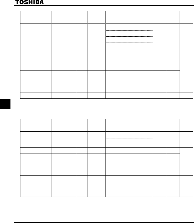
E6581160
54
7
Title Communication
No. Function Unit
Minimum
setting unit
Panel/Commun
ication
Adjustment range Default
setting
User
setting
Reference
E6581158
0: H and H
H and H
1: H or H
H and H
2: H and H
H or H
H 0139 Output terminal
logic selection
(RY-RC, OUT-
NO)
--
3: H or H
H or H
0 6.3.4
H 0167 Frequency
command
agreement
detection range
Hz 0.1/0.01 0.0-HJ 2.5 6.3.5
H 0170 Base frequency 2 Hz 0.1/0.01 25.0-500.0 50.0 (WP)
60.0
(WN, AN)
H 0171 Base frequency
voltage 2
V 1/0.1 50-330 (240V class)
50-660 (500/600V class)
* 3
H 0172 Torque boost
value 2
% 0.1/0.1 0.0-30.0 * 1
6.4.1
H 0173 Motor electronic-
thermal protection
level 2
%
(A)
1/1 10-100 100 5.13
6.4.1
H 0185 Stall prevention
level 2
%
(A)
1/1 10-199,
200 (disabled)
150 6.4.1
6.19.2
*1 : Default values vary depending on the capacity. See the table of page 64.
*3 : 230 (240V class), 460 (500V class), 575 (600V class)
•Frequency parameters
Title Communication
No. Function Unit
Minimum
setting unit
Panel/Commun
ication
Adjustment range Default
setting
User
setting
Reference
E6581158
0: HOQF (Switchable to H by
terminal input)
H 0200 Frequency priority
selection
--
1: HOQF (Switchable to H at
less than 1.0Hz of designated
frequency)
0 6.5.1
7.1
H 0201 VIA input point 1
setting
% 1/1 0-100 0
H 0202 VIA input point 1
frequency
Hz 0.1/0.01 0.0-500.0 0.0
H 0203 VIA input point 2
setting
% 1/1 0-100 100
H 0204 VIA input point 2
frequency
Hz 0.1/0.01 0.0-500.0 50.0 (WP)
60.0
(WN, AN)
6.5.2
H 0207 Frequency setting
mode
selection 2
- - 0: Built-in potentiometer
1: VIA
2: VIB
3: Operation panel
4: Serial communication
5: UP/DOWN from external contact
6: VIA + VIB (Override)
1 6.3.5
6.5.1
7.1
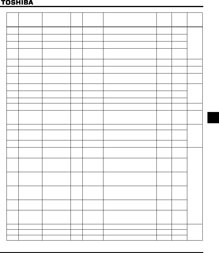
E6581160
55
7
Title Communication
No. Function Unit
Minimum
setting unit
Panel/Commun
ication
Adjustment range Default
setting
User
setting
Reference
E6581158
H 0210 VIB input point 1
setting
% 1/1 0-100 0
H 0211 VIB input point 1
frequency
Hz 0.1/0.01 0.0-500.0 0.0
H 0212 VIB input point 2
setting
% 1/1 0-100 100
H 0213 VIB input point 2
frequency
Hz 0.1/0.01 0.0-500.0 50.0 (WP)
60.0
(WN, AN)
6.5.2
H 0240 Starting frequency
setting
Hz 0.1/0.01 0.5-10.0 0.5 6.6.1
H 0241 Operation starting
frequency
Hz 0.1/0.01 0.0-HJ 0.0 6.6.2
H 0242 Operation starting
frequency
hysteresis
Hz 0.1/0.01 0.0-HJ 0.0 6.6.2
H 0250 DC braking
starting frequency
Hz 0.1/0.01 0.0-HJ 0.0 6.7.1
H 0251 DC braking
current
%(A) 1/1 0-100 50
H 0252 DC braking time s 0.1/0.1 0.0-20.0 1.0
H 0254 Motor shaft fixing
control
- - 0: Disabled
1: Enabled (after DC braking)
0 6.7.2
H 0256 Time limit for
lower-limit
frequency
operation
s 0.1/0.1 0: Disabled
0.1-600.0
0.0 6.8
H 0260 Jog run frequency Hz 0.1/0.01 H-20.0 5.0 6.9
H 0261 Jog run stopping
pattern
- - 0: Slowdown stop
1: Coast stop
2: DC braking
0
H 0262 Panel jog run
operation mode
- - 0: Invalid
1: Valid
0
H 0264 Input from
external contacts -
UP response time
s 0.1/0.1 0.0-10.0 0.1 6.5.2
H 0265 Input from
external contacts -
UP frequency step
width
Hz 0.1/0.01 0.0-HJ 0.1
H 0266 Input from
external contacts -
DOWN response
time
s 0.1/0.1 0.0-10.0 0.1
H 0267 Input from
external contacts -
DOWN frequency
step width
Hz 0.1/0.01 0.0-HJ 0.1
H 0268 Initial value of
UP/DOWN
frequency
Hz 0.1/0.01 NNWN 0.0
H 0269 Saving of changed
value of
UP/DOWN
frequency
- - 0: Not changed
1: Setting of H changed when
power is turned off
1
H 0270 Jump frequency 1 Hz 0.1/0.01 0.0-HJ 0.0 6.10
H 0271 Jumping width 1 Hz 0.1/0.01 0.0-30.0 0.0
H 0272 Jump frequency 2 Hz 0.1/0.01 0.0-HJ 0.0
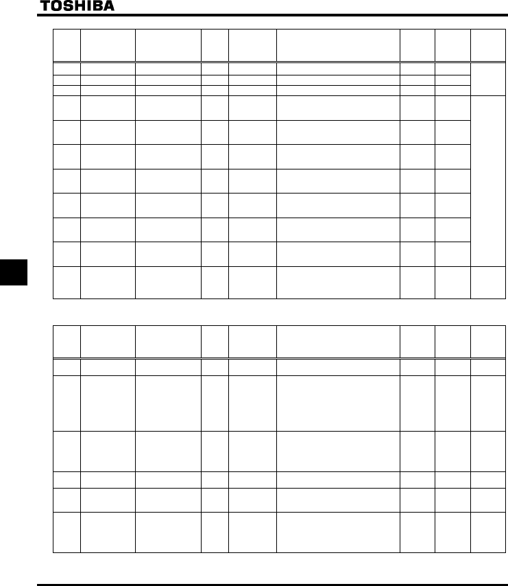
E6581160
56
7
Title Communication
No. Function Unit
Minimum
setting unit
Panel/Commun
ication
Adjustment range Default
setting
User
setting
Reference
E6581158
H 0273 Jumping width 2 Hz 0.1/0.01 0.0-30.0 0.0 6.10
H 0274 Jump frequency 3 Hz 0.1/0.01 0.0-HJ 0.0
H 0275 Jumping width 3 Hz 0.1/0.01 0.0-30.0 0.0
H 0287 Preset-speed
operation frequency
8
Hz 0.1/0.01 NN-WN 0.0
H 0288 Preset-speed
operation frequency
9
Hz 0.1/0.01 NN-WN 0.0
H 0289 Preset-speed
operation frequency
10
Hz 0.1/0.01 NN-WN 0.0
H 0290 Preset-speed
operation frequency
11
Hz 0.1/0.01 NN-WN 0.0
H 0291 Preset-speed
operation frequency
12
Hz 0.1/0.01 NN-WN 0.0
H 0292 Preset-speed
operation frequency
13
Hz 0.1/0.01 NN-WN 0.0
H 0293 Preset-speed
operation frequency
14
Hz 0.1/0.01 NN-WN 0.0
5.14
H 0294 Preset-speed
operation frequency
15
(Fire-speed)
Hz 0.1/0.01 NN-WN 0.0 5.14
6.11.2
•Operation mode parameters
Title Communication
No. Function Unit
Minimum
setting unit
Panel/Commun
ication
Adjustment range Default
setting
User
setting
Reference
E6581158
H 0300 PWM carrier
frequency
kHz 0.1/0.1 2.0 - 16.0 12.0 6.12
H 0301 Auto-restart
control selection
- - 0: Disabled
1: At auto-restart after momentary
stop
2: ST terminal on or off
3: At auto-restart or when turning ST-
CC on or off
4: At start-up
0 6.13.1
H 0302 Regenerative
power ride-
through control
(Deceleration
stop)
- - 0: Disabled
1: Automatic setting
2: Slowdown stop
0 6.13.2
H 0303 Retry selection
(number of times)
Times 1/1 0: Disabled
1-10
0 6.13.3
H 0304 Dynamic braking
selection
- - 0: Disabled
1: Enabled (Resistor overload
protection enabled)
0 6.13.4
H 0305 Overvoltage limit
operation
(Slowdown stop
mode selection)
- - 0: Enabled
1: Disabled
2: Enabled (Quick deceleration)
3: Enabled (Dynamic quick
deceleration)
2 6.13.5
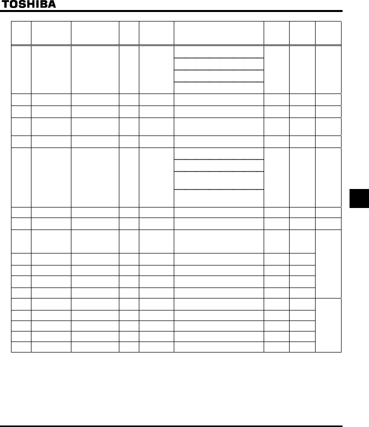
E6581160
57
7
Title Communication
No. Function Unit
Minimum
setting unit
Panel/Commun
ication
Adjustment range Default
setting
User
setting
Reference
E6581158
0: Supply voltage uncorrected, output
voltage limited
1: Supply voltage corrected, output
voltage limited
2: Supply voltage uncorrected, output
voltage unlimited
H 0307 Supply voltage
correction
(limitation of
output voltage)
--
3: Supply voltage corrected, output
voltage unlimited
2
(WP, WN)
3 (AN)
6.13.6
H 0308 Dynamic braking
resistance
Ω0.1/0.1 1.0-1000 * 1 6.13.4
H 0309 Dynamic braking
resistor capacity
kW 0.01/0.01 0.01-30.00 * 1 6.13.4
H 0311 Reverse-run
prohibition
- - 0: Forward/reverse run permitted
1: Reverse run prohibited
2: Forward run prohibited
0 6.13.7
H 0312 Random mode - - 0: Disabled
1: Automatic setting
06.12
0: Carrier frequency not reduced
automatically
1: Carrier frequency reduced
automatically
2: Carrier frequency not reduced
automatically
Support for 500V/600V models
H 0316 Carrier frequency
control mode
selection
--
3: Carrier frequency reduced
automatically
Support for 500V/600V models
16.12
H 0320 Droop gain %1/1 0-100 0 6.14
H 0323 Droop insensitive
torque band
%1/1 0-100 10 6.14
H 0342 Braking mode
selection
- - 0: Disabled
1: Enabled (forward run)
2: Enabled (reverse run)
3: Enabled (operating direction)
06.15
H 0343 Release
frequency
Hz 0.1/0.01 H-20.0 3.0
H 0344 Release time s 0.01/0.01 0.00-2.50 0.05
H 0345 Creeping
frequency
Hz 0.1/0.01 H-20.0 3.0
H 0346 Creeping time s 0.01/0.01 0.00-2.50 0.10
H 0359 PID control
waiting time
s 1/1 0-2400 0 6.16
H 0360 PID control - - 0: Disabled, 1: Enabled 0
H 0362 Proportional gain - 0.01/0.01 0.01-100.0 0.30
H 0363 Integral gain - 0.01/0.01 0.01-100.0 0.20
H 0366 Differential gain - 0.01/0.01 0.00-2.5 0.00
*1 : Default values vary depending on the capacity. See the table of 64.
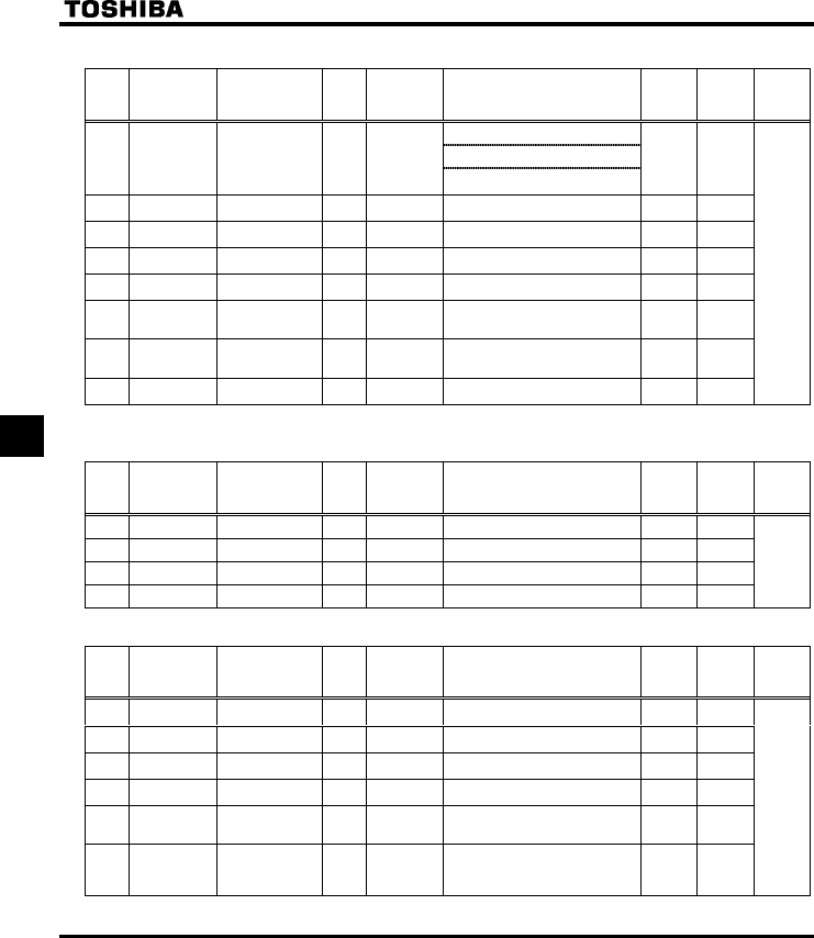
E6581160
58
7
•Torque boost parameters 1
Title Communication
No. Function Unit
Minimum
setting unit
Panel/Commun
ication
Adjustment range Default
setting
User
setting
Reference
E6581158
0: Auto-tuning disabled
1: Initialization of H (reset to 0)
H 0400 Auto-tuning - -
2: Auto-tuning enabled
(after execution: 0)
0
H 0401 Slip frequency
gain
% 1/1 0-150 50
H 0402 Automatic torque
boost value
% 0.1/0.1 0.0-30.0 * 1
H 0415 Motor rated
current
A 0.1/0.1 0.1-100.0 * 1
H 0416 Motor no-load
current
% 1/1 10-90 * 1
H 0417 Motor rated speed min-1 1/1 100-32000 1410(WP)
1710
(WN, AN)
H 0418 Speed control
response
coefficient
- 1/1 1-150 40
H 0419 Speed control
stability coefficient
- 1/1 1-100 20
5.11
6.17.1
*1 : Default values vary depending on the capacity. See the table of page 64.
•Input/output parameters 2
Title Communication
No. Function Unit
Minimum
setting unit
Panel/Commun
ication
Adjustment range Default
setting
User
setting
Reference
E6581158
H 0470 VIA input bias - - - -
H 0471 VIA input gain - - - -
H 0472 VIB input bias - - - -
H 0473 VIB input gain - - - -
6.5.4
•Torque boost parameters 2
Title Communication
No. Function Unit
Minimum
setting unit
Panel/Commun
ication
Adjustment range Default
setting
User
setting
Reference
E6581158
H 0480 Exciting current
coefficient
% 1/1 100-130 100
H 0485 Stall prevention
control coefficient 1
- 1/1 10-250 100
H 0492 Stall prevention
control coefficient 2
- 1/1 50-150 100
H 0494 Motor adjustment
coefficient
- 1/1 0-200 * 1
H 0495 Maximum voltage
adjustment
coefficient
% 1/1 90-110 104
H 0496 Waveform
switching
adjustment
coefficient
kHz 0.1/0.01 0.1-14.0 0.2
5.11
6.17.2
*1 : Default values vary depending on the capacity. See the table of page 64.
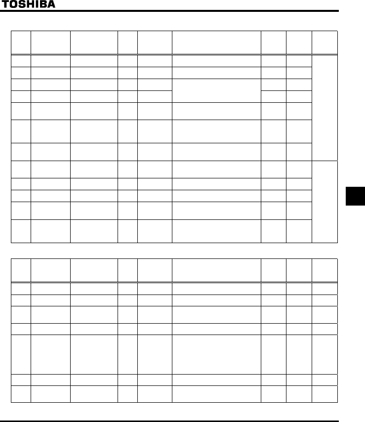
E6581160
59
7
•Acceleration/deceleration time parameters
Title Communication
No. Function Unit
Minimum
setting unit
Panel/Commun
ication
Adjustment range Default
setting
User
setting
Reference
E6581158
H 0500 Acceleration time
2
s 0.1/0.1 0.0-3200 10.0
H 0501 Deceleration time
2
s 0.1/0.1 0.0-3200 10.0
H 0502 Acceleration/decel
eration 1 pattern
-- 0
H 0503 Acceleration/decel
eration 2 pattern
--
0: Linear
1: S-pattern 1
2: S-pattern 2 0
H 0504 Acceleration/decel
eration selection
(1, 2 , 3)
- - 1: Acceleration/deceleration 1
2: Acceleration/deceleration 2
3: Acceleration/deceleration 3
1
H 0505 Acceleration/decel
eration 1 and 2
switching
frequency
Hz 0.1/0.01 0.0-WN 0.0
H 0506 S-pattern lower-
limit adjustment
amount
% 1/1 0-50 10
6.18
H 0507 S-pattern upper-
limit adjustment
amount
% 1/1 0-50 10
H 0510 Acceleration time
3
s 0.1/0.1 0.0-3200 10.0
H 0511 Deceleration time
3
s 0.1/0.1 0.0-3200 10.0
H 0512 Acceleration/decel
eration 3 pattern
- - 0: Linear
1: S-pattern 1
2: S-pattern 2
0
H 0513 Acceleration/decel
eration 2 and 3
switching
frequency
Hz 0.1/0.01 0.0-WN 0.0
6.18
•Protection parameters
Title Communication
No. Function Unit
Minimum
setting unit
Panel/Commun
ication
Adjustment range Default
setting
User
setting
Reference
E6581158
H 0601 Stall prevention
level 1
%
(A)
1/1 10-199,
200 (disabled)
150 6.19.2
H 0602 Inverter trip
retention selection
- - 0: Canceled with the power off
1: Still retained with the power off
0 6.19.3
H 0603 Emergency stop
selection
- - 0: Coast stop
1: Slowdown stop
2: Emergency DC braking
06.19.4
H 0604 Emergency DC
braking time
s0.1/0.1 0.0-20.0 1.0 6.19.4
H 0605 Output phase
failure detection
mode selection
--0: Disabled
1: At start-up (only one time after
power is turned on)
2: At start-up (each time)
3: During operation
4: At start-up + during operation
5: Detection of cutoff on output side
06.19.5
H 0607 Motor 150%-
overload time limit
s 1/1 10-2400 300 6.19.1
H 0608 Input phase failure
detection mode
selection
- - 0: Disabled, 1: Enabled 1 6.19.6

E6581160
60
7
Title Communication
No. Function Unit
Minimum
setting unit
Panel/Commun
ication
Adjustment range Default
setting
User
setting
Reference
E6581158
H 0609 Small current
detection current
hysteresis
% 1/1 1-20 10
H 0610 Small current
trip/alarm
selection
- - 0: Alarm only
1: Tripping
0
H 0611 Small current
detection current
%
(A)
1/1 0-100 0
H 0612 Small current
detection time
s 1/1 0-255 0
6.19.7
H 0613 Detection of
output short-circuit
during start-up
- - 0: Each time (standard pulse)
1: At start-up (only one time after
power is turned on)
(standard pulse)
2: Each time (short-time pulse)
3: At start-up (only one time after
power is turned on)
(short-time pulse)
0 6.19.8
H 0615 Over-torque
trip/alarm
selection
- - 0: Alarm only
1: Tripping
0
H 0616 Over-torque
detection level
%1/1 0-250 150
H 0618 Over-torque
detection time
s 0.1/0.1 0.0-10.0 0.5
6.19.9
H 0619 Over-torque
detection level
hysteresis
% 1/1 0-100 10 6.19.9
H 0621 Cumulative
operation time
alarm setting
100
Time
0.1/0.1
(=10 hours)
0.0-999.9 610 6.19.10
H 0626 Over-voltage stall
protection level
%1/1 100-150 *1 6.13.5
H 0627 Undervoltage
trip/alarm
selection
- - 0: Alarm only
(detection level below 60%)
1: Tripping
(detection level below 60%)
2: Alarm only
(detection level below 50%,
DC reactor necessary)
0 6.19.12
H 0633 Trip at VIA low
level input mode
%1/1 0: Disabled, 1-100 0 6.19.13
H 0634 Annual average
ambient
temperature (parts
replacement
alarms)
- - 1: -10 to +10°C
2: 11-20°C
3: 21-30°C
4: 31-40°C
5: 41-50°C
6: 51-60°C
3 6.19.14
*1 : Default values vary depending on the capacity. See the table of 64.
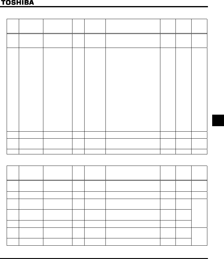
E6581160
61
7
•Output parameters
Title Communication
No. Function Unit
Minimum
setting unit
Panel/Commun
ication
Adjustment range Default
setting
User
setting
Reference
E6581158
H 0669 Logic output/pulse
train output
selection (OUT-
NO)
- - 0: Logic output
1: Pulse train output
0 6.20.1
H 0676 Pulse train output
function selection
(OUT-NO)
--
0: Output frequency
1: Output current
2: Set frequency
3: DC voltage
4: Output voltage command value
5: Input power
6: Output power
7: Torque
8: Torque current
9: Motor cumulative load factor
10: Inverter cumulative load factor
11: PBR (braking reactor) cumulative
load factor
12: Frequency setting value (after
PID)
13: VIA/II Input value
14: VIB Input value
15: Fixed output 1 (Output current:
100%)
16: Fixed output 2 (Output current:
50%)
17: Fixed output 3
(Other than the output current:
100%)
0 6.20.1
H 0677 Maximum numbers
of pulse train
pps 1/1 500-1600 800 6.20.1
H 0691 Inclination
characteristic of
analog output
- - 0: Negative inclination (downward
slope)
1: Positive inclination (upward slope)
1 6.20.2
H 0692 Meter bias % 1/1 0-100 0 6.20.2
•Operation panel parameters
Title Communication
No. Function Unit
Minimum
setting unit
Panel/Commun
ication
Adjustment range Default
setting
User
setting
Reference
E6581158
H 0700 Prohibition of
change of
parameter settings
- - 0: Permitted
1: Prohibited
0 6.21.1
H 0701 Unit selection - - 0: %
1: A (ampere)/V (volt)
0 6.21.2
H 0702 Free unit selection Times 0.01/0.01 0.00: Free unit display disabled
(display of frequency)
0.01-200.0
0.00
H 0705 Inclination
characteristic of
free unit display
- - 0: Negative inclination (downward
slope)
1: Positive inclination (upward slope)
1
H 0706 Free unit display
bias
Hz 0.01/0.01 0.00-HJ 0.00
6.21.3
H 0707 Free step 1
(pressing a panel
key once)
Hz 0.01/0.01 0.00: Disabled
0.01-HJ
0.00
H 0708 Free step 2 (panel
display)
- 1/1 0: Disabled
1-255
0
6.21.4

E6581160
62
7
Title Communication
No. Function Unit
Minimum
setting unit
Panel/Commun
ication
Adjustment range Default
setting
User
setting
Reference
E6581158
H 0710 Standard monitor
display selection
- - 0: Operation frequency (Hz/free unit)
1: Frequency command (Hz/free unit)
2: Output current (%/A)
3: Inverter rated current (A)
4: Inverter load factor (%)
5: Output power (%)
6: Frequency command after PID
control (Hz/free unit)
7: Optional item specified from an
external control unit
0 6.21.5
H 0719 Canceling of
operation
command when
standby terminal
(ST) is turned off
- - 0: Operation command canceled
(cleared)
1: Operation command retained
1 6.21.6
H 0721 Panel stop pattern - - 0: Slowdown stop
1: Coast stop
0 6.21.7
H 0730 Prohibition of
frequency setting
on the operation
panel (HE)
- - 0: Permitted
1: Prohibited
0
H 0733 Panel operation
prohibition
(RUN/STOP keys)
- - 0: Permitted
1: Prohibited
0
H 0734 Prohibition of
panel emergency
stop operation
- - 0: Permitted
1: Prohibited
0
H 0735 Prohibition of
panel reset
operation
- - 0: Permitted
1: Prohibited
0
H 0736 Prohibition of
change of EOQF
/ HOQF during
operation
- - 0: Permitted
1: Prohibited
1
6.21.1
•Communication parameters
Title Communication
No. Function Unit
Minimum
setting unit
Panel/Commun
ication
Adjustment range Default
setting
User
setting
Reference
E6581158
H 0800 Communication
rate
- - 0: 1200bps
1: 2400bps
2: 4800bps
3: 9600bps
4: 19200bps
3
H 0801 Parity - - 0: NON (No parity)
1: EVEN (Even parity)
2: ODD (Odd parity)
1
H 0802 Inverter number - 1/1 0-255 0
H 0803 Communication
error trip time
s 1/1 0: (disabled)
1-100
0
H 0805 Communication
waiting time
s 0.01/0.01 0.00-2.00 0.00
H 0806 Setting of master
and slave for
communication
between inverters
- - 0: Slave (0 Hz command issued in
case the master inverter fails)
1: Slave (Operation continued in case
the master inverter fails)
2: Slave (Emergency stop tripping in
case the master inverter fails)
3: Master (transmission of frequency
commands)
4: Master (transmission of output
frequency signals)
0
6.22
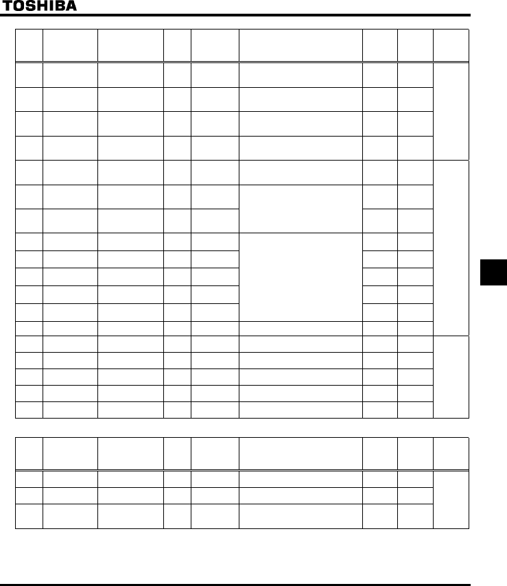
E6581160
63
7
Title Communication
No. Function Unit
Minimum
setting unit
Panel/Commun
ication
Adjustment range Default
setting
User
setting
Reference
E6581158
H 0811 Communication
command point 1
setting
% 1/1 0-100 0
H 0812 Communication
command point 1
frequency
Hz 0.1/0.01 0.0-500.0 0.0
H 0813 Communication
command point 2
setting
% 1/1 0-100 100
H 0814 Communication
command point 2
frequency
Hz 0.1/0.01 0.0-500.0 50.0 (WP)
60.0
(WN, AN)
6.5.2
6.22.1
H 0829 Selection of
communication
protocol
- - 0: Toshiba inverter protocol
1: Modbus RTU protocol
0
H 0870 Block write data 1 - - 0
H 0871 Block write data 2 - -
0: No selection
1: Command information 1
2: Command information 2
3: Frequency command
4: Output data on the terminal board
5: Analog output for communications
0
H 0875 Block read data 1 - - 0
H 0876 Block read data 2 - - 0
H 0877 Block read data 3 - - 0
H 0878 Block read data 4 - - 0
H 0879 Block read data 5 - -
0: No selection
1: Status information
2: Output frequency
3: Output current
4: Output voltage
5: Alarm information
6: PID feedback value
7: Input terminal board monitor
8: Output terminal board monitor
9: VIA terminal board monitor
10: VIB terminal board monitor
0
H 0880 Free notes - 1/1 0-65535 0
6.22
H 0890 Parameter for
option 1
- 1/1 0-65535 0 6.23
H 0891 Parameter for
option 2
- 1/1 0-65535 0
H 0892 Parameter for
option 3
- 1/1 0-65535 0
H 0893 Parameter for
option 4
- 1/1 0-65535 0
H 0894 Parameter for
option 5
- 1/1 0-65535 0
•PM motor parameters
Title Communication
No. Function Unit
Minimum
setting unit
Panel/Commun
ication
Adjustment range Default
setting
User
setting
Reference
E6581158
H 0910 Step-out detection
current level
%
(A)
1/1 10-150 100
H 0911 Step-out detection
time
s 1/1 0.0: No detection
0.1-25.0
0.0
H 0912 High-speed torque
adjustment
coefficient
- 0.01/0.01 0.00-650.0 0.00
6.24
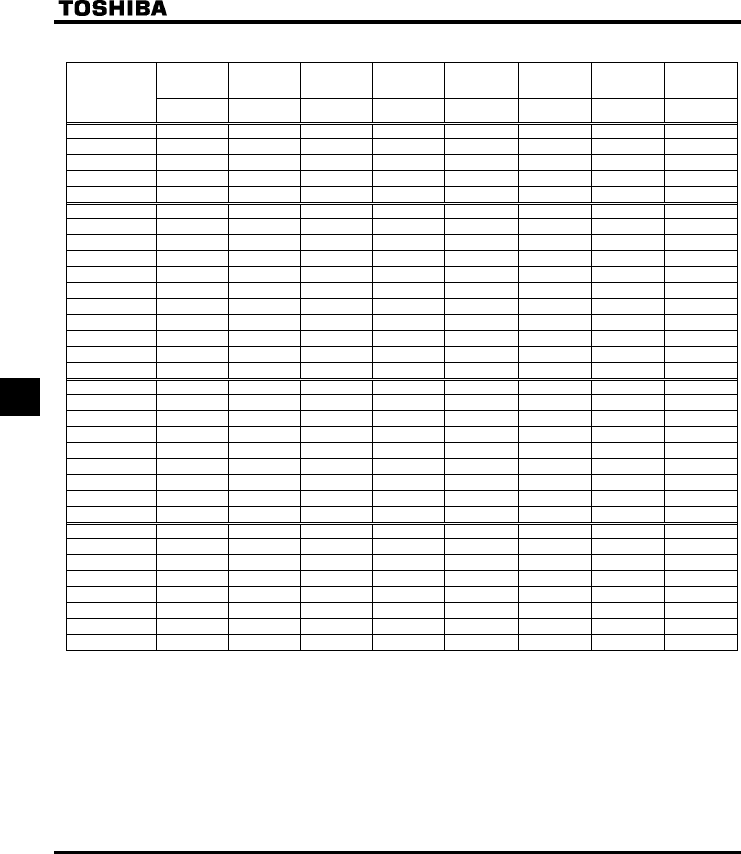
E6581160
64
7
QDefault settings by inverter rating
Inverter type
Torque boost
value 1/2
Dynamic
braking
resistance
Dynamic
braking resistor
capacity
Automatic
torgue boost
value
Motor rated
current
Motor no-load
current
Motor
adjustment
coefficient
Over-voltage
stall protection
level
XD/H
(%)
H
(Ω) (Note)
H
(kW)
H
(%)
H
(A)
H
(%)
H H
(%)
VFS11S-2002PL 6.0 200.0 0.12 8.3 1.2 70 90 134
VFS11S-2004PL 6.0 200.0 0.12 6.2 2.0 65 90 134
VFS11S-2007PL 6.0 200.0 0.12 5.8 3.4 60 80 134
VFS11S-2015PL 6.0 75.0 0.12 4.3 6.2 55 70 134
VFS11S-2022PL 5.0 75.0 0.12 4.1 8.9 52 70 134
VFS11-2002PM 6.0 200.0 0.12 8.3 1.2 70 90 134
VFS11-2004PM 6.0 200.0 0.12 6.2 2.0 65 90 134
VFS11-2005PM 6.0 200.0 0.12 6.0 2.7 62 80 134
VFS11-2007PM 6.0 200.0 0.12 5.8 3.4 60 80 134
VFS11-2015PM 6.0 75.0 0.12 4.3 6.2 55 70 134
VFS11-2022PM 5.0 75.0 0.12 4.1 8.9 52 70 134
VFS11-2037PM 5.0 40.0 0.12 3.4 14.8 48 70 134
VFS11-2055PM 4.0 20.0 0.24 3.0 21.0 46 70 134
VFS11-2075PM 3.0 15.0 0.44 2.5 28.2 43 70 134
VFS11-2110PM 2.0 10.0 0.66 2.3 40.6 41 60 134
VFS11-2150PM 2.0 7.5 0.88 2.0 54.6 38 50 134
VFS11-4004PL 6.0 200.0 0.12 6.2 1.0 65 90 140
VFS11-4007PL 6.0 200.0 0.12 5.8 1.7 60 80 140
VFS11-4015PL 6.0 200.0 0.12 4.3 3.1 55 70 140
VFS11-4022PL 5.0 200.0 0.12 4.1 4.5 52 70 140
VFS11-4037PL 5.0 160.0 0.12 3.4 7.4 48 70 140
VFS11-4055PL 4.0 80.0 0.24 2.6 10.5 46 70 140
VFS11-4075PL 3.0 60.0 0.44 2.3 14.1 43 70 140
VFS11-4110PL 2.0 40.0 0.66 2.2 20.3 41 60 140
VFS11-4150PL 2.0 30.0 0.88 1.9 27.3 38 50 140
VFS11-6007P 3.0 285.0 0.06 3.8 1.1 61 80 134
VFS11-6015P 3.0 145.0 0.12 3.8 2.1 59 70 134
VFS11-6022P 3.0 95.0 0.18 3.2 3.0 54 70 134
VFS11-6037P 3.0 48.0 0.37 3.5 4.9 50 70 134
VFS11-6055P 2.0 29.0 0.61 2.0 7.3 55 70 134
VFS11-6075P 2.0 29.0 0.61 1.5 9.5 51 70 134
VFS11-6110P 2.0 19.0 0.92 1.9 14.5 55 60 134
VFS11-6150P 1.0 14.0 1.23 1.7 19.3 53 50 134
Note: Be sure to set f308 (Dynamic braking resistance) at the resistance of the dynamic braking resistor connected.
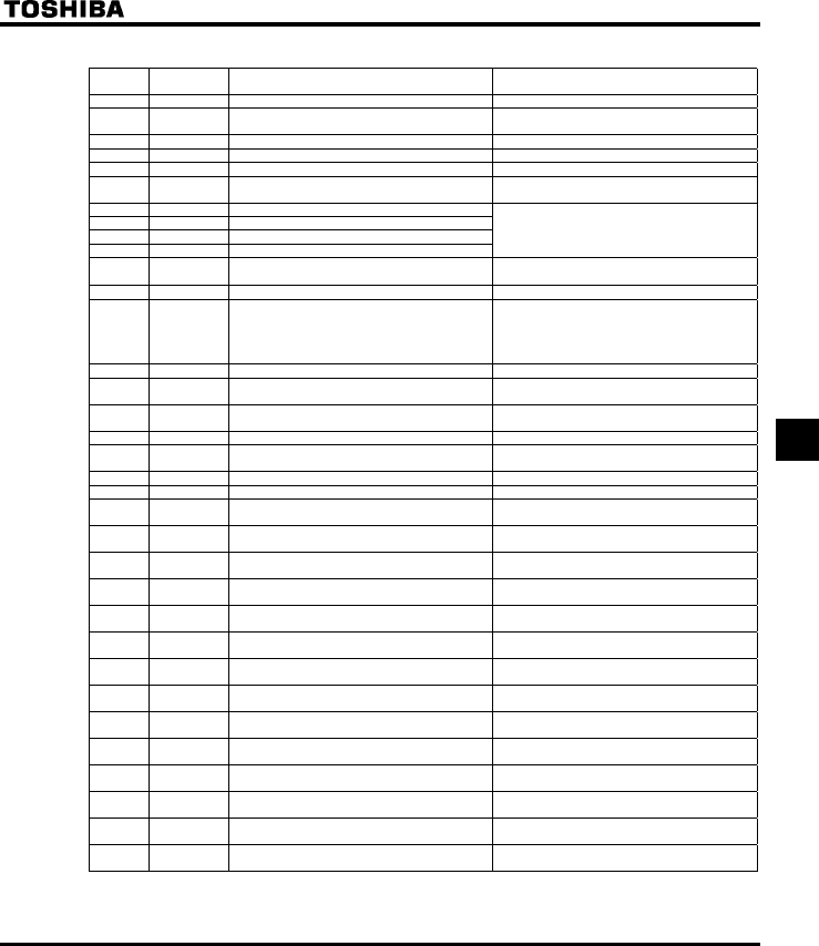
E6581160
65
7
QTable of input terminal functions 1
Function
No. Code Function Action
0 - No function is assigned Disabled
1 ST Standby terminal ON: Ready for operation
OFF: Coast stop (gate off)
2 F Forward run command ON: Forward run OFF: Slowdown stop
3 R Reverse run command ON: Reverse run OFF: Slowdown stop
4 JOG Jog run mode ON: Jog run, OFF: Jog run canceled
5 AD2 Acceleration/deceleration 2 pattern selection ON: Acceleration/deceleration 2
OFF: Acceleration/deceleration 1 or 3
6 SS1 Preset-speed command 1
7 SS2 Preset-speed command 2
8 SS3 Preset-speed command 3
9 SS4 Preset-speed command 4
Selection of 15-speed with SS1 to SS4 (4 bits)
10 RES Reset command ON: Acceptance of reset command
ON → OFF: Trip reset
11 EXT Trip stop command from external input device ON: G Trip stop
12 CFMOD Switching of command mode and frequency
setting mode
ON: Forced switching from command mode to
terminal input mode, forced switching from
frequency setting mode to the mode
commanded between HOQF and H.
(If H = )
13 DB DC braking command ON: DC braking
14 PID PID control prohibited ON: PID control prohibited
OFF: PID control permitted
15 PWENE Permission of parameter editing ON: Parameter editing permitted
OFF: Parameter editing prohibited (If H = )
16 ST+RES Combination of standby and reset commands ON: Simultaneous input from ST and RES
17 ST+CFMOD Combination of standby and command/frequency
setting mode switching
ON: Simultaneous input from ST and CFMOD
18 F+JOG Combination of forward run and jog run ON: Simultaneous input from F and JOG
19 R+JOG Combination of reverse run and jog run ON: Simultaneous input from R and JOG
20 F+AD2 Combination of forward run and
acceleration/deceleration 2
ON: Simultaneous input from F and AD2
21 R+AD2 Combination of reverse run and
acceleration/deceleration 2
ON: Simultaneous input from R and AD2
22 F+SS1 Combination of forward run and preset-speed
command 1
ON: Simultaneous input from F and SS1
23 R+SS1 Combination of reverse run and preset-speed
command 1
ON: Simultaneous input from R and SS1
24 F+SS2 Combination of forward run and preset-speed
command 2
ON: Simultaneous input from F and SS2
25 R+SS2 Combination of reverse run and preset-speed
command 2
ON: Simultaneous input from R and SS2
26 F+SS3 Combination of forward run and preset-speed
command 3
ON: Simultaneous input from F and SS3
27 R+SS3 Combination of reverse run and preset-speed
command 3
ON: Simultaneous input from R and SS3
28 F+SS4 Combination of forward run and preset-speed
command 4
ON: Simultaneous input from F and SS4
29 R+SS4 Combination of reverse run and preset-speed
command 4
ON: Simultaneous input from R and SS4
30 F+SS1+AD2 Combination of forward run, preset-speed
command 1 and acceleration/deceleration 2
ON: Simultaneous input from F, SS1 and AD2
31 R+SS1+AD2 Combination of reverse run, preset-speed
command 1 and acceleration/deceleration 2
ON: Simultaneous input from R, SS1 and AD2
32 F+SS2+AD2 Combination of forward run, preset-speed
command 2 and acceleration/deceleration 2
ON: Simultaneous input from F, SS2 and AD2
33 R+SS2+AD2 Combination of reverse run, preset-speed
command 2 and acceleration/deceleration 2
ON: Simultaneous input from R, SS2 and AD2
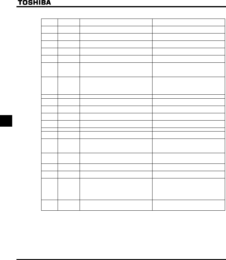
E6581160
66
7
QTable of input terminal functions 2
Function
No. Code Function Action
34 F+SS3+AD2 Combination of forward run, preset-speed
command 3 and acceleration/deceleration 2
ON: Simultaneous input from F, SS3 and AD2
35 R+SS3+AD2 Combination of reverse run, preset-speed
command 3 and acceleration/deceleration 2
ON: Simultaneous input from R, SS3 and AD2
36 F+SS4+AD2 Combination of forward run, preset-speed
command 4 and acceleration/deceleration 2
ON: Simultaneous input from F, SS4 and AD2
37 R+SS4+AD2 Combination of reverse run, preset-speed
command 4 and acceleration/deceleration 2
ON: Simultaneous input from R, SS4 and AD2
38 FCHG Frequency command forced switching ON: H (If H = )
OFF: HOQF
39 VF2 No.2 Switching of V/F setting ON: No.2 V/F setting
(RV=0, H, H, H, H)
OFF: No.1 V/F setting
(Set value of RV, XN, XNX, XD, VJT)
40 MOT2 No.2 motor switching
(VF2+AD2+OCS2)
ON: No.2 motor
(RV=0, H, H, H, H,
H, H, H, H)
OFF: No.1 motor (Set value of RV, XN, XNX,
XD, VJT, CEE, FGE, H, H)
41 UP Frequency UP signal input from external contacts ON: Increase in frequency
42 DOWN Frequency DOWN signal input from external
contacts
ON: Reduction in frequency
43 CLR Frequency UP/DOWN cancellation signal input
from external contacts
OFF→ON: Resetting of UP/DOWN frequency by
means of external contacts
44 CLR+RES Combination of frequency UP/DOWN cancellation
and reset by means of external contacts
ON: Simultaneous input from CLR and RES
45 EXTN Inversion of trip stop command from external
device
OFF: G Trip stop
46 OH Thermal trip stop signal input from external device ON: QJ Trip stop
47 OHN Inversion of thermal trip stop command from
external device
OFF: QJ Trip stop
48 SC/LC Forced switching from remote to local control Enabled when remote control is exercised
ON: Local control (setting of cmod, HOQF and
H)
OFF: Remote control
49 HD Operation holding (stop of 3-wire operation) ON: F (forward run)/R: (reverse run) held, 3-wire
operation
OFF: Slowdown stop
50 CMTP Forced switching of command mode and terminal
board command
ON: Terminal board operation
OFF: Setting of EOQF
51 CKWH Display cancellation of the cumulative power
amount (kWh)
ON: Monitor display cancellation of the cumulative
power amount (kWh)
52 FORCE Forced operation (factory configuration required) ON: Forced operation mode in which operation is
not stopped in the event of the occurrence of
a soft fault (preset speed operation frequency
15) To use this function, the inverter needs to
be so configured at the factory.
OFF: Normal operation
53 FIRE Fire-speed control ON: Fire-speed operation (preset speed operation
frequency 15)
OFF: Normal operation
Note. When function 1, 10-12, 15-17, 38, 41-45 or 48 is assigned to an input terminal board, the input terminal
board is enabled even if the parameter command mode selection cmod is set at 1 (panel).
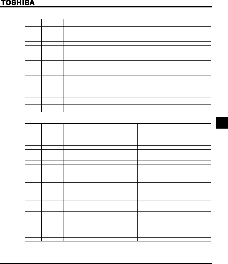
E6581160
67
7
QTable of input terminal functions 3
Function
No. Code Function Action
54 STN Coast stop (gate off) ON: Coast stop (gate off)
55 RESN Inversion of RES ON: Acceptance of reset command
OFF→ ON: Trip reset
56 F+ST Combination of forward run and standby ON: Simultaneous input from F and ST
57 R+ST Combination of reverse run and standby ON: Simultaneous input from R and ST
58 AD3 Acceleration/deceleration 3 selection ON: Acceleration/deceleration 3
OFF: Acceleration/deceleration 1 or 2
59 F+AD3 Combination of forward run and
acceleration/deceleration 3
ON: Simultaneous input from F and AD3
60 R+AD3 Combination of reverse run and
acceleration/deceleration 3
ON: Simultaneous input from R and AD3
61 OCS2 Forced switching of stall prevention level 2 ON: Enabled at the value of H
OFF: Enabled at the value of H
62 HDRY Holding of RY-RC terminal output ON: Once turned on, RY-RC are held on.
OFF: The status of RY-RC changes in real time
according to conditions.
63 HDOUT Holding of OUT-NO terminal output ON: Once turned on, OUT-NO are held on.
OFF: The status of OUT-NO changes in real time
according to conditions.
64 PRUN Cancellation (clearing) of operation command from
panel
0: Operation command canceled (cleared)
1: Operation command retained
65 ICLR PID control integral value clear ON: PID control integral value always zero
OFF: PID control permitted
QTable of output terminal functions 1
Function
No.
Code Function Action
0 LL Frequency lower limit ON: The output frequency is above the NN set
value.
OFF: The output frequency is equal to or less than
the NN set value.
1 LLN Inversion of frequency lower limit Inversion of LL setting
2 UL Frequency upper limit ON: Output frequency is equal to or higher than
WN value.
OFF: Output frequency is lower than WN value.
3 ULN Inversion of frequency upper limit Inversion of UL setting
4 LOW Low-speed detection signal ON: Output frequency is equal to or higher than
H value.
OFF: Output frequency is lower than H
value.
5 LOWN Inversion of low-speed detection signal Inversion of LOW setting
6 RCH Designated frequency attainment signal
(completion of acceleration/deceleration)
ON: The output frequency is equal to or less than
the specified frequency ± frequency set with
H.
OFF: The output frequency is above the specified
frequency ± frequency set with H.
7 RCHN Inversion of designated frequency attainment
signal (inversion of completion of
acceleration/deceleration)
Inversion of RCH setting
8 RCHF Set frequency attainment signal ON: The output frequency is equal to or less than
the frequency set with H ± H.
OFF: The output frequency is above the frequency
set with H ± H.
9 RCHFN Inversion of set frequency attainment signal Inversion of RCHF setting
10 FL Failure signal (trip output) ON: When inverter is tripped
OFF: When inverter is not tripped
11 FLN Inversion of failure signal (inversion of trip output) Inversion of FL setting

E6581160
68
7
QTable of output terminal functions 2
Function
No. Code Function Action
12 OT Over-torque detection ON: Torque current is equal to or larger than
H set value and longer than H
set time.
OFF: The torque current is equal to or less than
(H set value - H set value).
13 OTN Inversion of over-torque detection Inversion of OT
14 RUN Start/Stop ON: When operation frequency is output or during
(FD)
OFF: Operation stopped
15 RUNN Inversion of RUN/STOP Inversion of RUN setting
16 POL OL pre-alarm ON: 50% or more of calculated value of overload
protection level
OFF: Less than 50% of calculated value of
overload protection level
17 POLN Inversion of OL pre-alarm Inversion of POL setting
18 POHR Braking resistor overload pre-alarm ON: 50% or more of calculated value of H
set overload protection level
OFF: Less than 50% of calculated value of
H set overload protection level
19 POHRN Inversion of braking resistor overload pre-alarm Inversion of RCHR setting
20 POT Over-torque detection pre-alarm ON: Torque current is equal to or larger than 70%
of H set value.
OFF: The torque current is below (H set
value x 70% - H set value).
21 POTN Inversion of over-torque detection pre-alarm Inversion of POT setting
22 PAL Pre-alarm One of the following is turned on:
ON POL, POHR, POT, MOFF, UC, OT, LL
stop, COT, and momentary power failure
slowdown stop.
or E,R,QTJ issues an alarm
All the following are turned off:
OFF POL, POHR, POT, MOFF, UC, OT, LL
stop, COT, and momentary power failure
slowdown stop.
or E,R,QTJ issues no alarm
23 PALN Inversion of pre-alarm Inversion of PAL setting
24 UC Small-current detection ON: The output current is equal to or less than
H set value for H set time.
OFF: The output current is equal to or larger than
H set value + 10%.
25 UCN Inversion of small-current detection Inversion of UC setting
26 HFL Significant failure ON: QEC,QEN,QV,G,
GGR,GVP,GRJQ,GTT-
,QJ,WR,GH,WE,
GV[R,QTGRJ)
OFF: Failure other than the above
27 HFLN Inversion of significant failure Inversion of HFL setting
28 LFL Insignificant failure ON: (QE-,QR-,QJ,
QN-,QNT)
OFF: Failure other than the above
29 LFLN Inversion of insignificant failure Inversion of LFL setting
30 RDY1 Ready for operation (including ST/RUN) ON: Ready for operation (ST and RUN are also
ON)
OFF: Others
31 RDY1N Inversion of ready for operation (including
ST/RUN)
Inversion of RDY1 setting
32 RDY2 Ready for operation (excluding ST/RUN) ON: Ready for operation (ST and RUN are not
ON)
OFF: Others
33 RDY2N Inversion of ready for operation (excluding ST/RUN) Inv ersion of RDY2
34 FCVIB Frequency VIB selection ON: VIB selected as frequency command
OFF: Terminal other than VIB selected as
frequency command
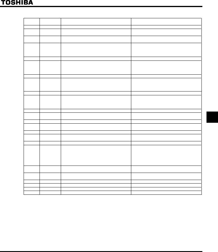
E6581160
69
7
QTable of output terminal functions 3
Function
No. Code Function Action
35 FCVIBN Inversion of frequency VIB selection Inversion of FCVIB
36 FLR Fault signal (put out also at the time of a retry) ON: When inverter trips or retries
OFF: When inverter does not trip or retry
37 FLRN Inversion of failure signal (put out also at the time
of a retry)
Inversion of FLR
38 OUT0 Specified data output 1 ON: Specified data from remote control FA50:
BIT0= 1
OFF: Specified data from remote control FA50:
BIT0= 0
39 OUT0N Inversion of specified data output 1 Inversion of OUT0 setting
40 OUT1 Specified data output 2 ON: Specified data from remote control FA50:
BIT1= 1
OFF: Specified data from remote control FA50:
BIT1= 0
41 OUT1N Inversion of specified data output 2 Inversion of OUT1 setting
42 COT Cumulative operation time alarm ON: Cumulative operation time is equal to or
longer than H
OFF: Cumulative operation time is shorter than
H
43 COTN Inversion of cumulative operation time alarm Inversion of COT
44 LTA Parts replacement alarm ON: Calculation for parts replacement time is
equal to or longer than the preset time
ON: Calculation for parts replancement time is
shorter than the preset time
45 LTAN Inversion of replacement alarm Inversion of LTA
46 BR Braking sequence output ON: Braking retention signal
OFF: Braking release signal
47 BRN Inversion of braking sequence output Inversion of BR
48 LI1 F terminal input signal ON: The signal input to F terminal is ON
OFF: The signal input to F terminal is OFF
49 LI1N Inversion of F terminal input signal Inversion of LI1
50 LI2 R terminal input signal ON: The signal input to R terminal is ON
OFF: The signal input to R terminal is OFF
51 LI2N Inversion of R terminal input signal Inversion of LI2
52 PIDF Signal in accordance of frequency command ON: Frequency commanded by HOQF or
H and that by VIA show the same
value.
OFF: Frequency commanded by HOQF or
H and that by VIA show different
values.
53 PIDFN Inversion of signal in accordance of frequency
command
Inversion of PIDF setting
54 MOFF Undervoltage detection ON: Undervoltage detected
OFF: Other than undervoltage
55 MOFFN Inversion of undervoltage detection Inversion of MOFF
56-253 Disabled Invalid settings, always OFF (ignored) Invalid settings, always OFF (ignored)
254 AOFF Always OFF Always OFF
255 AON Always ON Always ON
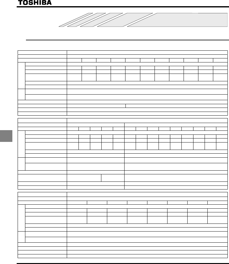
E6581160
70
8
8. Specifications
8.1 Models and their standard specifications
QStandard specifications
Item Specification
Input voltage 3-phase 240V
Applicable motor (kW) 0.2 0.4 0.55 0.75 1.5 2.2 4.0 5.5 7.5 11 15
Type VFS11
Form 2002PM 2004PM 2005PM 2007PM 2015PM 2022PM 2037PM 2055PM 2075PM 2110PM 2150PM
Capacity (kVA) Note 1) 0.6 1.3 1.4 1.8 3.0 4.2 6.7 10 13 21 25
Rated output/current
(A) Note 2)
1.5
(1.5)
3.3
(3.3)
3.7
(3.3)
4.8
(4.4)
8.0
(7.9)
11.0
(10.0)
17.5
(16.4)
27.5
(25.0)
33
(33)
54
(49)
66
(60)
Output voltage Note 3) 3-phase 200V to 240V
Rating
Overload current rating 150%-60 seconds, 200%-0.5 second
Voltage-frequency 3-phase 200V to 240V - 50/60Hz
Power
supply
Allowable fluctuation Voltage + 10%, -15% Note 4), frequency ±5%
Protective method IP20 Enclosed type (JEM1030)
Cooling method Self-cooling Forced air-cooled
Color Munsel 5Y-8/0.5
Built-in filter Basic filter
Item Specification
Input voltage 1-phase 240V 3-phase 500V
Applicable motor (kW) 0.2 0.4 0.75 1.5 2.2 0.4 0.75 1.5 2.2 4.0 5.5 7.5 11 15
Type VFS11S VFS11
Form 2002PL 2004PL 2007PL 2015PL 2022PL 4004PL 4007PL 4015PL 4022PL 4037PL 4055PL 4075PL 4110PL 4150PL
Capacity (kVA) Note 1) 0.6 1.3 1.8 3.0 4.2 1.1 1.8 3.1 4.2 7.2 11 13 21 25
Rated output current
(A) Note 2)
1.5
(1.5)
3.3
(3.3)
4.8
(4.4)
8.0
(7.9)
11.0
(10.0)
1.5
(1.5)
2.3
(2.1)
4.1
(3.7)
5.5
(5.0)
9.5
(8.6)
14.3
(13.0)
17.0
(17.0)
27.7
(25.0)
33
(30)
Rated output voltage Note 3) 3-phase 200V to 240V 3-phase 380V to 500V
Rating
Overload current rating 150%-60 seconds, 200%-0.5 second 150%-60 seconds, 200% -0.5 second
Voltage-current 1-phase 200V to 240V – 50/60Hz 3-phase 380V to 500V - 50/60Hz
Power
supply
Allowable fluctuation Voltage + 10%、-15% Note 4),
frequency±5%Voltage + 10%, -15% Note 4), frequency ±5%
Protective method, IP20 Enclosed type (JEM1030) IP20 Enclosed type (JEM1030)
Cooling method Self-cooling Forced air-
cooled Forced air-cooled
Color Munsel 5Y-8/0.5 Munsel 5Y-8/0.5
Built-in filter EMI filter EMI filter
Item Specification
Input voltage 3-phase 600V
Applicable motor (kW) 0.75 1.5 2.2 4.0 5.5 7.5 11 15
Type VFS11-
Form 6007P 6015P 6022P 6037P 6055P 6075P 6110P 6150P
Capacity (kVA) Note 1) 1.7 2.7 3.9 6.1 9 11 17 22
Rated output/current
(A) Note 2)
1.7
(1.5)
2.7
(2.4)
3.9
(3.5)
6.1
(5.5)
9.0
(8.1)
11.0
(9.9)
17.0
(15.3)
22.0
(19.8)
Output voltage Note 3) 3-phase 525V to 600V
Rating
Overload current rating 150%-60 seconds, 200%-0.5 second
Voltage-frequency 3-phase 525V to 600V - 50/60Hz
Power
supply
Allowable fluctuation Voltage + 10%, -15% Note 4), frequency ±5%
Protective method IP20 Enclosed type (JEM1030)
Cooling method Forced air-cooled
Color Munsel 5Y-8/0.5
Built-in filter No filter
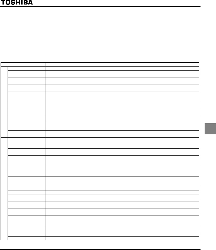
E6581160
71
8
Note 1. Capacity is calculated at 220V for the 240V models, at 440V for the 500V models and at 575V for the 600V models.
Note 2. Indicates rated output current setting when the PWM carrier frequency (parameter F300) is 4kHz or less. When
exceeding 4kHz, the rated output current setting is indicated in the parentheses. It needs to be further reduced for
PWM carrier frequencies above 12 kHz.
The rated output current is reduced even further for 500V models with a supply voltage of 480V or more.
The default setting of the PWM carrier frequency is 12kHz.
Note 3. Maximum output voltage is the same as the input voltage.
Note 4. ±10% when the inverter is used continuously (load of 100%).
Note 5. If you are using 600V model, be sure to connect an input reactor (ACL).
QCommon specification
Item Specification
Control system Sinusoidal PWM control
Rated output voltage Adjustable within the range of 50 to 600V by correcting the supply voltage (not adjustable above the input voltage)
Output frequency range 0.5 to 500.0Hz, default setting: 0.5 to 80Hz, maximum frequency: 30 to 500Hz
Minimum setting steps of
frequency
0.1Hz: analog input (when the max. frequency is 100Hz), 0.01Hz: Operation panel setting and communication
setting.
Frequency accuracy Digital setting: within ±0.01% of the max. frequency (-10 to +60°C)
Analog setting: within ±0.5% of the max. frequency (25°C ±10°C)
Voltage/frequency
characteristics
V/f constant, variable torque, automatic torque boost, vector control, automatic energy-saving, dynamic automatic
energy-saving control, PM motor control. Auto-tuning. Base frequency (25 - 500Hz) adjusting to 1 or 2, torque boost
(0 - 30%) adjusting to 1 or 2, adjusting frequency at start (0.5 - 10Hz)
Frequency setting signal Potentiometer on the front panel, external frequency potentiometer (connectable to a potentiometer with a rated
impedance of 1 - 10kΩ), 0 - 10Vdc (input impedance: VIA/VIB=30kΩ, 4 - 20mAdc (Input impedance: 250Ω).
Terminal board base
frequency
The characteristic can be set arbitrarily by two-point setting. Possible to set individually for three functions: analog
input (VIA and VIB) and communication command.
Frequency jump Three frequencies can be set. Setting of the jump frequency and the range.
Upper- and lower-limit
frequencies
Upper-limit frequency: 0 to max. frequency, lower-limit frequency: 0 to upper-limit frequency
PWM carrier frequency Adjustable within a range of 2.0 to 16.0Hz (default: 12kHz).
Principal control functions
PID control Setting of proportional gain, integral gain, differential gain and control wait time. Checking whether the amount of
processing amount and the amount of feedback agree.
Acceleration/deceleration
time
Selectable from among acceleration/deceleration times 1, 2 and 3 (0.0 to 3200 sec.). Automatic
acceleration/deceleration function. S-pattern acceleration/deceleration 1 and 2 and S-pattern adjustable. Control of
forced rapid deceleration and dynamic rapid deceleration
DC braking Braking start-up frequency: 0 to maximum frequency, braking rate: 0 to 100%, braking time: 0 to 20 seconds,
emergency DC braking, motor shaft fixing control
Dynamic braking Control and drive circuit is built in the inverter with the braking resistor outside (optional).
Input terminal function
(programmable)
Possible to select from among 66 functions, such as forward/reverse run signal input, jog run signal input, operation
base signal input and reset signal input, to assign to 8 input terminals. Logic selectable between sink and source.
Output terminal functions
(programmable)
Possible to select from among 58 functions, such as upper/lower limit frequency signal output, low speed detection
signal output, specified speed reach signal output and failure signal output, to assign to FL relay output, open
collector output and RY output terminals.
Forward/reverse run The RUN and STOP keys on the operation panel are used to start and stop operation, respectively. The switching
between forward run and reverse run can be done from one of the three control units: operation panel, terminal
board and external control unit.
Jog run Jog mode, if selected, allows jog operation from the operation panel or the terminal board.
Preset speed operation Base frequency + 15-speed operation possible by changing the combination of 4 contacts on the terminal board.
Retry operation Capable of restarting automatically after a check of the main circuit elements in case the protective function is
activated. 10 times (Max.) (selectable with a parameter)
Various prohibition
settings
Possible to write-protect parameters and to prohibit the change of panel frequency settings and the use of operation
panel for operation, emergency stop or resetting.
Regenerative power ride-
through control
Possible to keep the motor running using its regenerative energy in case of a momentary power failure (default:
OFF).
Auto-restart operation In the event of a momentary power failure, the inverter reads the rotational speed of the coasting motor and outputs
a frequency appropriate to the rotational speed in order to restart the motor smoothly. This function can also be
used when switching to commercial power.
Drooping function When two or more inverters are used to operate a single load, this function prevents load from concentrating on one
inverter due to unbalance.
Override function The sum of two analog signals (VIA/VIB) can be used as a frequency command value.
Operation specifications
Failure detection signal 1c-contact output: (250Vac-0.5A-cosφ=0.4)
<Continued overleaf>
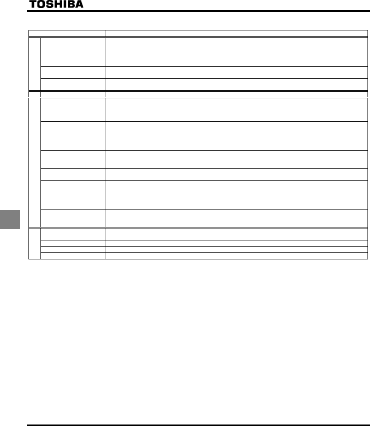
E6581160
72
8
<Continued>
Item Specification
Protective function Stall prevention, current limitation, over-current, output short circuit, over-voltage, over-voltage limitation,
undervoltage, ground fault, power supply phase failure, output phase failure, overload protection by electronic
thermal function, armature over-current at start-up, load side over-current at start-up, over-torque, undercurrent,
overheating, cumulative operation time, life alarm, emergency stop, braking resistor over-current/overload, various
pre-alarms
Electronic thermal
characteristic
Switching between standard motor and constant-torque VF motor, switching between motors 1 and 2, setting of
overload trip time, adjustment of stall prevention levels 1 and 2, selection of overload stall
Protective function
Reset function Function of resetting by closing contact 1a or by turning off power or the operation panel. This function is also used
to save and clear trip records.
Alarms Stall prevention, overvoltage, overload, under-voltage, setting error, retry in process, upper/lower limits
Causes of failures Over-current, overvoltage, overheating, short-circuit in load, ground fault, overload on inverter, over-current through
arm at start-up, over-current through load at start-up, CPU fault, EEPROM fault, RAM fault, ROM fault,
communication error. (Selectable: Overload of braking resistor, emergency stop, under-voltage, low voltage, over-
torque, motor overload, output open-phase)
Monitoring function Operation frequency, operation frequency command, forward/reverse run, output current, voltage in DC section,
output voltage, torque, torque current, load factor of inverter, integral load factor of PBR, input power, output power,
information on input terminals, information on output terminals, version of CPU1, version of CPU2, version of
memory, PID feedback amount, frequency command (after PID), integral input power, integral output power, rated
current, causes of past trips 1 through 4, parts replacement alarm, cumulative operation time
Past trip monitoring
function
Stores data on the past four trips: number of trips that occurred in succession, operation frequency, direction of
rotation, load current, input voltage, output voltage, information on input terminals, information on output terminals,
and cumulative operation time when each trip occurred.
Output for frequency
meter
Analog output: (1mAdc full-scale DC ammeter or 7.5Vdc full-scale DC ammeter / Rectifier-type AC voltmeter, 225%
current Max. 1mAdc, 7.5Vdc full-scale), 4 to 20mA/0 to 20mA output
4-digit 7-segments LED Frequency: inverter output frequency.
Alarm: stall alarm “C”, overvoltage alarm “P”, overload alarm “L”, overheat alarm “H”.
Status: inverter status (frequency, cause of activation of protective function, input/output voltage, output
current, etc.) and parameter settings.
Free-unit display: arbitrary unit (e.g. rotating speed) corresponding to output frequency.
Display function
Indicator Lamps indicating the inverter status by lighting, such as RUN lamp, MON lamp, PRG lamp, % lamp, Hz lamp,
frequency setting potentiometer lamp, UP/DOWN key lamp and RUN key lamp. The charge lamp indicates that the
main circuit capacitors are electrically charged.
Use environments Indoor, altitude: 1000m (Max.), not exposed to direct sunlight, corrosive gas, explosive gas or vibration (less than
5.9m/s2) (10 to 55Hz)
Ambient temperature -10 to +60°C Note)1.2.
Storage temperature -20 to +65°C
Environments
Relative humidity 20 to 93% (free from condensation and vapor).
Note 1. Above 40°C : Remove the protective seal from the top of VF-S11.
If the ambient temperature is above 50°C: Remove the seal from the top of the inverter and use the inverter with the
rated output current reduced.
Note 2. If inverters are installed side by side (with no sufficient space left between them): Remove the seal from the top of
each inverter.
When installing the inverter where the ambient temperature will rise above 40°C, remove the seal from the top of the
inverter and use the inverter with the rated output current reduced.

E6581160
73
8
8.2 Outside dimensions and mass
QOutside dimensions and mass
Dimensions (mm)
Voltage class Applicable motor
(kW) Inverter type W H D W1H1H2D2
Drawing Approx. weight
(kg)
0.2 VFS11S-2002PL 1.0
0.4 VFS11S-2004PL 130 1.0
0.75 VFS11S-2007PL
72 130
140
60 15 A
1.2
1.5 VFS11S-2015PL 105 130 150 93
121.5
13 B 1.4
1-phase 240V
2.2 VFS11S-2022PL 140 170 150 126 157 14
8
C2.2
0.2 VFS11-2002PM 0.9
0.4 VFS11-2004PM 120 0.9
0.55 VFS11-2005PM 1.1
0.75 VFS11-2007PM
72 130 60 15 A
1.1
1.5 VFS11-2015PM
130
1.2
2.2 VFS11-2022PM 105 130 150 93
121.5
13 B 1.3
4.0 VFS11-2037PM 140 170 150 126 157 14 C 2.2
5.5 VFS11-2055PM 4.8
7.5 VFS11-2075PM 180 220 170 160 210 12 D 4.9
11 VFS11-2110PM 9.3
3-phase 240V
15 VFS11-2150PM 245 310 190 225 295 19.5
8
E9.6
0.4 VFS11-4004PL 1.4
0.75 VFS11-4007PL 1.5
1.5 VFS11-4015PL
105 130 150 93 121.5 13 B
1.5
2.2 VFS11-4022PL 2.3
4.0 VFS11-4037PL 140 170 150 126 157 14 C 2.5
5.5 VFS11-4055PL 5.0
7.5 VFS11-4075PL 180 220 170 160 210 12 D 5.1
11 VFS11-4110PL 9.6
3-phase 500V
15 VFS11-4150PL 245 310 190 225 295 19.5
8
E9.6
0.75 VFS11-6007P 1.3
1.5 VFS11-6015P 105 130 150 93 121.5 13 B 1.3
2.2 VFS11-6022P 2.1
4.0 VFS11-6037P 140 170 150 126 157 14 C 2.2
5.5 VFS11-6055P 4.7
7.5 VFS11-6075P 180 220 170 160 210 12 D 4.7
11 VFS11-6110P 8.8
3-phase 600V
15 VFS11-6150P 245 310 190 225 295 19.5
8
E8.8
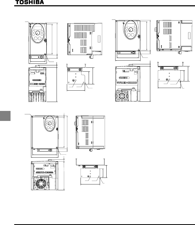
E6581160
74
8
QOutline drawing
130
R2.5
15
121.5(Installation dimension)
60
f
5
D8
64.5
50
68
M5 4-M4
EMC plate
VF-S11
72
(Installation
dimension)
130
R2.5
13
121.5(Installation dimension)
93(Installation dimension)
f
5
D8
64.5
50
95
M5 4-M4
EMC plate
VF-S11
105
Fig.A Fig.B
170
2-R2.5
14
65
157(Installation dimension)
126(Installation dimension)
2-
f
25
150 8
62
48
95
M5 4-M4
EMC plate
VF-S11
140
Fig.C
Note 1. To make it easier to grasp the dimensions of
each inverter, dimensions common to all inverters in
these figures are shown with numeric values but not
with symbols.
Here are the meanings of the symbols used.
W: Width
H: Height
D: Depth
W1: Mounting dimension (horizontal)
H1: Mounting dimension (vertical)
H2: Height of EMC plate mounting area
D2: Depth of frequency setting knob
Note 2. Here are the avaiable EMC plate
Fig.A : EMP003Z (Approx. weight : 0.1kg)
Fig.B, Fig.C : EMP004Z (Approx. weight : 0.1kg)
Fig.D : EMP005Z (Approx. weight : 0.3kg)
Fig.E : EMP006Z (Approx. weight : 0.3kg)
Note 3. The models shown in Fig. A and Fig. B are
fixed at two points: in the upper left and lower right
corners.
Note 4. The model shown in Fig. A is not equipped with
a cooling fan.
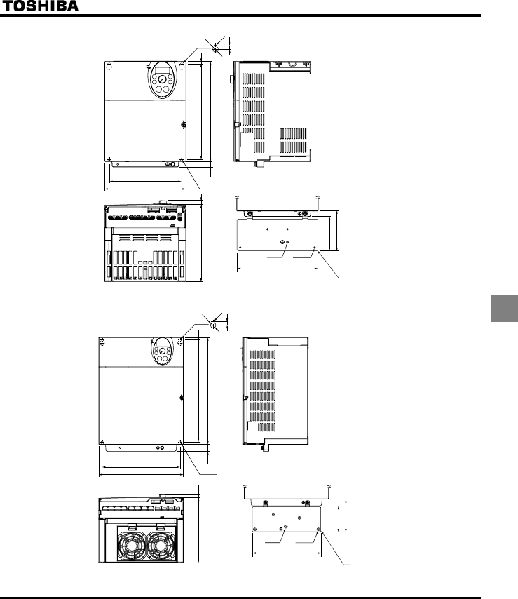
E6581160
75
8
180
178
2-R2.5
160(Installation dimension)
220
170 8
87
75
12
210(Installation dimension) 5
f13
R2.5
8
VF-S11
M5 4-M4
EMC plate
Fig.D
245
198
225 (Installation dimension)
190 8
31019.5
295(Installation dimension) 7
f14
R3
9
VF-S11
94.5
75
M4 4-M4
EMC plate
2-R3
Fig.E

E6581160
76
9
9. Before making a service call
- Trip information and remedies
9.1 Trip causes/warnings and remedies
When a problem arises, diagnose it in accordance with the following table.
If it is found that replacement of parts is required or the problem cannot be solved by any remedy described in the
table, contact your Toshiba dealer.
[Trip information]
Error code Failure code Problem Possible causes Remedies
QE
QER
0001
0025
Overcurrent during
acceleration
Overcurrent flowing
in element during
acceleration
•The acceleration time CEE is too short.
•The V/F setting is improper.
•A restart signal is imput to the rotating
motor after a momentary stop, etc.
•A special motor (e.g. motor with a small
impedance) is used.
•Increase the acceleration time CEE.
•Check the V/F parameter.
•Use H (auto-restart) and H
(ride-through control).
•Adjust the carrier frequency H.
•Set the carrier frequency control mode
selection parameter f316 to 1 or 3
(carrier frequency decreased
automatically).
QE
QER
0002
0026
Overcurrent during
deceleration
Overcurrent flowing
in element during
decelearion
•The deceleration time FGE is too short. •Increase the deceleration time FGE.
•Set the carrier frequency control mode
selection parameter f316 to 1 or 3
(carrier frequency decreased
automatically).
QE
QER
0003
0027
Overcurrent during
constant speed
operation
Overcurrent flowing
in element during
operation
•The load fluctuates abruptly.
•The load is in an abnormal condition.
•Reduce the load fluctuation.
•Check the load (operated machine).
•Set the carrier frequency control mode
selection parameter f316 to 1 or 3
(carrier frequency decreased
automatically).
ER
ER
ER
0025
0026
0027
Ground fault trip
Arm overcurrent at
start-up
(for 11 and 15 kW
models only)
•A current leaked from an output cable or
the motor to ground.
•A main circuit elements is defective.
•Check cables, connectors, and so on for
ground faults.
•Make a service call.
QEN 0004 Overcurrent (An
overcurrent on the
load side at start-up)
•The insulation of the output main circuit or
motor is defective.
•The motor has too small impedance.
•A 11 or 15 kW model was started,
although a current is leaked from an
output cable or the motor to ground.
•Check the cables and wires for defective
insulation.
•When using a 11 or 15 kW model, check
cables, connectors, and so on for ground
faults.
QEC 0005 Arm overcurrent at
start-up
•A main circuit elements is defective. •Make a service call.
*
GRJ
0008 Input phase failure •A phase failure occured in the input line of
the main circuit.
•The capacitor in the main circuit lacks
capacitance.
•Check the main circuit input line for phase
failure.
•Enable H (input phase failure
detection).
•Check the capacitor in the main circuit for
exhaustion.
*
GRJQ
0009 Output phase failure •A phase failure occurred in the output line
of the main circuit.
•Check the main circuit output line, motor,
etc. for phase failure.
•Enable H (Output phase failure
detection).
* You can select a trip ON/OFF by parameters.
(Continued overleaf)

E6581160
77
9
(Continued)
Error code Failure code Problem Possible causes Remedies
QR 000A Overvoltage during
acceleration
•The imput voltage fluctuates abnormally.
(1) The power supply has a capacity of
200kVA or more.
(2) A power factor improvement capacitor is
opened or closed.
(3) A system using a thyrister is connected
to the same power distribution line.
•A restart signal is input to the rotating
motor after a momentary stop, etc.
•Insert a suitable input reactor.
•Use H (auto-restart) and H
(ride-through control).
QR 000B Overvoltage during
deceleration
•The deceleration time FGE is too short.
(Regenerative energy is too large.)
•H (dynamic braking resistor) is off.
•H (overvoltage limit operation) is
off.
•The input voltage fluctuates abnormally.
(1) The power supply has a capacity of
200kVA or more.
(2) A power factor improvement capacitor is
opened and closed.
(3) A system using a thyrister is connected
to the same power distribution line.
•Increase the deceleration time FGE.
•Install a dynamic braking resistor.
•Enable H (dynamic braking
resistor).
•Enable H (overvoltage limit
operation).
•Insert a suitable input reactor.
QR 000C Overvoltage during
constant-speed
operation
•The input voltage fluctuates abnormally.
(1) The power supply has a capacity of
200kVA or more.
(2) A power factor improvement capacitor is
opened or closed.
(3) A system using a thyrister is connected
to the same power distribution line.
•The motor is in a regenerative state
because the load causes the motor to run
at a frequency higher than the inverter
output frequency.
•Insert a suitable input reactor.
•Install a dynamic braking resistor.
QN 000D Inverter overload •The acceleration time ACC is too short.
•The DC braking amout is too large.
•The V/F setting is improper.
•A restart signal is input to the rotating
motor after a momentary stop, etc.
•The load is too large.
•Increase the acceleration time CEE.
•Reduce the DC braking amount H
and the DC braking time H.
•Check the V/F parameter setting.
•Use H (auto-restart) and H
(ride-through control).
•Use an inverter with a larger rating.
QN 000E Motor overload •The V/F setting is improper.
•The motor is locked up.
•Low-speed operation is performed
continuously.
•An excessive load is applied to the motor
during operation.
•Check the V/F parameter setting.
•Check the load (operated machine).
•Adjust QNO to the overload that the
motor can withstand during operation in a
low speed range.
QNT 000F Dynamic braking
resistor
overload trip
•The deceleration time is too short.
•Dynamic braking is too large.
•Increase the deceleration time FGE.
•Increase the capacity of dynamic braking
resistor (wattage) and adjust PBR
capacity parameter H.
*
QV
0020 Over-torque trip •Over-torque reaches to a detection level
during operation.
•Enable H (over-torque trip
selection).
•Check system error.
QJ 0010 Overheat •The cooling fan does not rotate.
•The ambient temperature is too high.
•The vent is blocked up.
•A heat generating device is installed close
to the inverter.
•The thermistor in the unit is broken.
•Restart the operation by resetting the
inverter after it has cooled down enough.
•The fan requires replacement if it does
not rotate during operation.
•Secure sufficient space around the
inverter.
•Do not place any heat generating device
near the inverter.
•Make a service call.
* You can select a trip ON/OFF by parameters.
(Continued overleaf)

E6581160
78
9
(Continued)
Error code Failure code Problem Possible causes Remedies
QJ 002E External thermal trip •An external thermal trip is input. •Check the external thermal input.
G0011 Emergency stop •During automatic operation or remote
operation, a stop command is entered
from the operation panel or a remote
input device.
•Reset the inverter.
GGR 0012 EEPROM fault 1 •A data writing error occurs. •Turn off the inverter, then turn it again. If it
does not recover from the error, make a
service call.
GGR 0013 EEPROM fault 2 •Power supply is cut off during V[R
operation and data writing is aborted.
•Turn the power off temporarily and turn it
back on, and then try V[R operation
again.
GGR 0014 EEPROM fault 3 •A data reading error occurred. •Turn off the inverter, then turn it again. If it
does not recover from the error, make a
service call.
GTT 0015 Main unit RAM fault •The control RAM is defective. •Make a service call.
GTT 0016 Main unit ROM fault •The control ROM is defective. •Make a service call.
GTT 0017 CPU fault 1 •The control CPU is defective. •Make a service call.
GTT 0018 Remote control error •An error arises during remote operation. •Check the remote control device, cables,
etc.
GTT 001A Current detector fault •The current detector is defective. •Make a service call.
GTT 001B Optional circuit board
format error
•An optional circuit board in a different
format is installed.
•Check again to be sure that the circuit
board is connected correctly, and then
reset the power supply.
•Replace the circuit board with a correctly
formatted one.
*
WE
001D Low-current
operation
Trip
•The output current decreased to a low-
current detection level during operation.
•Enable H (low-current detection).
•Check the suitable detection level for the
system (H, H).
•Make a service call if the setting is
correct.
*
WR
001E Undervoltage trip
(main circuit)
•The input voltage (in the main circuit) is
too low.
•Check the input voltage.
•Enable H (undervoltage trip
selection).
•To cope with a momentary stop due to
undervoltage, enable H (ride-
through control) and H (auto-
restart).
GH 0022 Ground fault trip •A ground fault occurs in the output cable
or the motor.
•Check the cable and the motor for ground
faults.
GVP 0054 Auto-tuning error •Check the motor parameter H to H.
•The motor with the capacity of 2 classes or less than the inverter is used.
•The output cable is too thin.
•The motor is rotating.
•The inverter is used for loads other than those of three-phase induction motors.
GV[R 0029 Inverter
type error
•Circuit board is changed.
(Or main circuit/drive circuit board)
•Make a service call.
*
G
0032 Brea in analog signal
cable
•The signal input via VIA is below the
analog sinal detectio level set with
H.
•Check the cables for breaks. And check
the setting of input signal or setting value
of H.
G 0033 CPU
communications
error
•A communications error occurs between
control CPUs.
•Make a service call.
G 0034 Excessive torque
boosted
•The torque boost parameter H is
set too high.
•The motor has too small impedance.
•Decrease the setting of the torque boost
parameter H.
G 0035 CPU fault 2 •The control CPU is defective. •Make a service call.
UQWV 002F Step-out
(For PM motor only)
•The motor shaft is locked.
•One output phase is open.
•An impact load is applied.
•Unlock the motor shaft.
•Check the interconnect cables between
the inverter and the motor.
* You can select a trip ON/OFF by parameters.
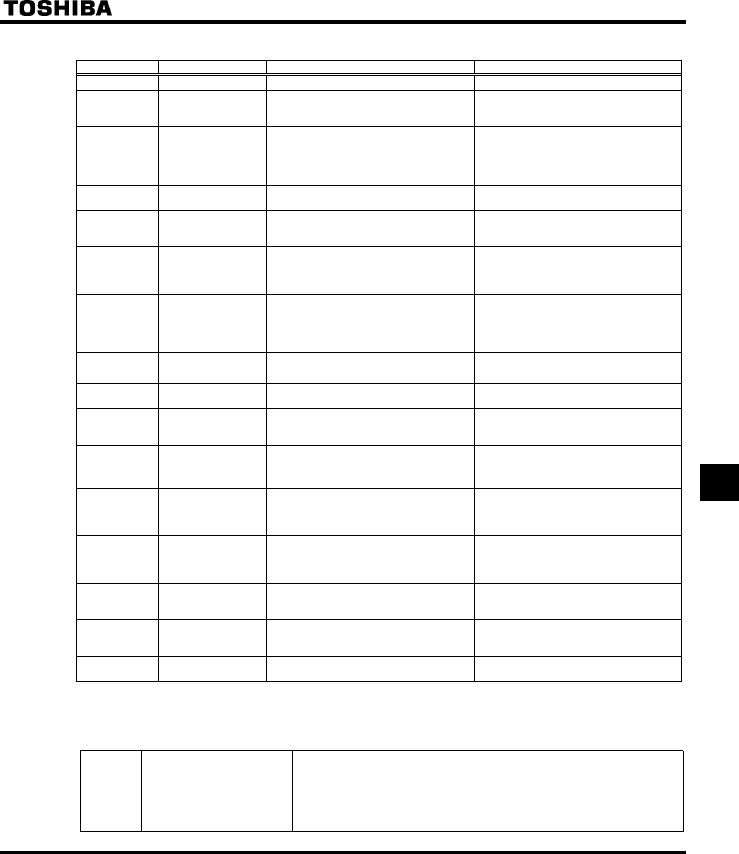
E6581160
79
9
[Alarm information] Each message in the table is displayed to give a warning but does not cause the inverter to trip.
Error code Problem Possible causes Remedies
QHH ST terminal OFF •The ST-CC circuit is opened. •Close the ST-CC circuit.
OQHH Undervoltage in main
circuit
•The supply voltage between R, S and T is
under voltage.
•Measure the main circuit supply voltage.
If the voltage is at a normal level, the
inverter requires repairing.
TVT[ Retry in process •The inverter is n the process of retry.
•A momentary stop occurred.
•The inverter is normal if it restarts after
several tens of senconds.
The inverter restarts automatically. Be
careful of the machine because it may
suddenly restart.
GTT Frequency point
setting error alarm
•The frequency setting signals at points 1
and 2 are set too close to each other.
•Set the frequency setting signals at points
1 and 2 apart from each other.
ENT Clear command
acceptable
•This message is displayed when pressing
the STOP key while an error code is
displayed.
•Press the STOP key again to clear the
trip.
GQHH Emergency stop
command
acceptable
•The operation panel is used to stop the
operation in automatic control or remote
control mode.
•Press the STOP key for an emergency
stop.
To cancel the emergency stop, press any
other key.
J/
NQ
Setting error alarm /
An error code and
data are displayed
alternately twice
each.
•An error is found in a setting when data is
reading or writing.
•Check whether the setting is made
correctly.
JGCF/
GPF
Display of first/last
data items
•The first and last data item in the CWJ
data group is displayed.
•Press MODE key to exit the data group.
FD DC braking •DC braking in process •The message goes off in several tens of
seconds if no problem occurs. Note)
FDZP Shaft fixing control •Motor shaft fixing control is in process. •Normal if the message disappears when
a stop command is entered (or the
operation command is canceled).
G
G
G
Flowing out of
excess number of
digits
•The number of digits such as frequencies
is more than 4.
(The upper digits have a priority.)
•Lower the fequency free unit
magnification H.
UVQR Momentary power
failure slowdown
stop prohibition
function activated.
•The slowdown stop prohibition function
set with H (momentary power
failure ride-through operation) is
activated.
•To restart operation, reset the inverter or
input an operation signal again.
NUVR Auto-stop because of
continuous operation
at the lower-limit
frequency
•The automatic stop function selected with
H was activated.
•To deactivate the automatic stop function,
increase the frequency command above
the lower-limit frequency (LL) + 0.2 Hz or
turn off the operation command.
KPKV Parameters in the
process of
initialization
•Parameters are being initialized to default
values.
•Normal if the message disappears after a
while (several seconds to several tens of
seconds).
G Operation panel key
fault
•The RUN or STOP key is held down for
more than 20 seconds.
•The RUN or STOP key is faulty.
•Check the operation panel.
CVP Auto-tuning •Auto-tuning in process •Normal if it the message disappears after
a few seconds.
Note) When the ON/OFF function is selected for DC braking (DB), using the input terminal selection parameter, you can judge
the inverter to be normal if “FD” disappears when opening the circuit between the terminal and CC.
[Prealarm display]
EOvercurrent alarm Same as QE (overcurrent)
ROvervoltage alarm Same as QR (overvoltage)
NOverload alarm Same as QN and QN (overload)
JOverheat alarm Same as QJ (overheat)

Simplified manualIndustrial Inverter TOSVERT VF-S11
2
1
3
4
5
6
7
8
9
9
10
11
12
13
14
15
16
E6581160
Connection
I
Safety
precautions
Contents
Read first
Operations
Basic VF-S11
operations
Monitoring the
operation status
Measures
to satisfy the
standards
Table of
parameters
and data
Specifications
Before making
a service call
Measures
to satisfy the
standards
Peripheral
devices
Table of
parameters
and data
Specifications
Before making a service
call - Trip information and
remedies
Inspection and
maintenance
Warranty
Disposal of the
inverter
NOTICE
1.Make sure that this instruction manual is delivered to the
end user of the inverter unit.
2.Read this manual before installing or operating the inverter
unit, and store it in a safe place for reference.
TOSVERTTM VF-S11
< Simplified manual >
1-phase 240V class 0.2 2.2kW
3-phase 240V class 0.4 15kW
3-phase 500V class 0.4 15kW
3-phase 600V class 0.75 15kW
2004 Ver. 108/109
TOSHIBA
INDUSTRIAL AND POWER
SYSTEMS & SERVICES COMPANY
OVERSEAS SALES & MARKETING DEPT.
ELECTRICAL APPARATUS & MEASUREMENT DIV.
1-1, Shibaura 1-chome, Minato-Ku,
Tokyo 105-8001, Japan
TEL: +81-(0)3-3457-4911
FAX: +81-(0)3-5444-9268
TOSHIBA INTERNATIONAL CORPORATION
13131 West Little York RD., Houston,
TX 77041, U.S.A
TEL: +1-713-466-0277
FAX: +1-713-896-5226
TOSHIBA ASIA PACIFIC PTE., LTD
152 Beach Rd., #16-00 Gateway East,
Singapore 189721
TEL: +65-6297-0900
FAX: +65-6297-5510
TOSHIBA CHINA CO., LTD
23rd Floor, HSBC Tower, 101 Yin Cheng
East Road, Pudong New Area, Shanghai
200120, The People's Republic of China
TEL: +86-(0)21-6841-5666
FAX: +86-(0)21-6841-1161
TOSHIBA INTERNATIONAL CORPORATION PTY., LTD
2 Morton Street Parramatta, NSW2150, Australia
TEL: +61-(0)2-9768-6600
FAX: +61-(0)2-9890-7542
TOSHIBA INFORMATION, INDUSTRIAL AND POWER
SYSTEMS TAIWAN CORP.
6F, No66, Sec1 Shin Sheng N.RD, Taipei, Taiwan
TEL: +886-(0)2-2581-3639
FAX: +886-(0)2-2581-3631
For further information, please contact your nearest Toshiba Liaison Representative or International Operations - Producer Goods.
The data given in this manual are subject to change without notice.
2004-12
Instruction Manual
Industrial Inverter
For 3-phase induction motors
