Tosibox LOCK100 Wireless Router User Manual tosibox user manual big indd
Tosibox Oy Wireless Router tosibox user manual big indd
Tosibox >
User manual

1
User Manual v2.10
Copyright © Tosibox Oy 2014

2
Table of Contents
Tosibox overview 3
Lock connections 4
Tosibox glossary 5
Tosibox products and accessories 6
Key user interface 7
Lock user interface 8
Tosibox Key and Lock serialization 9
Deploying the Lock 11
Deploying the Key 16
Renaming and using devices 19
Multiple Keys 20
Remote serialization of additional Keys 23
Creating a Backup Key 25
Using the Mobile Client 26
Connecting Locks 31
Logging into the Lock 31
Updating the software 34
3G modem for the Lock 35
Key connection settings for the Lock 35
Industry settings for the Lock 36
Wireless settings for the Lock 37
Internet connection priorities 38
PUK code for the Key 40
Troubleshooting 41
Maintenance instructions 42
Technical Data for the Lock 43
Technical Data for the Key 44
Tosibox licences 45
Declaration of conformity 46
Sisällysluettelo
Tosibox lyhyesti 3
Lukon liitännät 4
Tosibox sanastoa 5
Tosibox tuotteet ja tarvikkeet 6
Avaimen käyttöliittymä 7
Lukon käyttöliittymä 8
Avaimen (Key) ja lukon (Lock) sarjoitus 9
Lukon käyttöönotto 11
Avaimen käyttöönotto 16
Laitteiden nimeäminen ja käyttäminen 19
Lisäavainten käyttöönotto 20
Lisäavainten etäsarjoitus 23
Vara-avaimen luonti 25
Mobile Clientin käyttäminen 26
Lukkojen yhdistäminen 31
Lukkoon kirjautuminen 31
Ohjelmiston päivitys 34
Lukon 3G-modeemi -asetukset 35
Lukon avainyhteys asetukset 35
Lukon Industry-asetukset 36
Lukon Wireless-asetukset 37
Internetyhteyksien prioriteetit 38
Avaimen PUK-koodi 40
Ongelmatilanteet 41
Huolto-ohjeita 42
Tosibox – tekniset tiedot - Lukko 43
Tosibox – tekniset tiedot - Avain 44
Tosibox-lisenssit 45
Vaatimustenmukaisuusilmoitus 46

3
Tosibox overview
Tosibox offers a new, automatic way to establish
a remote connection easily, quickly and securely.
Tosibox is the world’s only remote access device
with Plug & Go technology. All you need to use it
is a power outlet and an internet connection. The
operating principle of Tosibox resembles that of a
physical Lock and key.
The solution consists of a key device (Key) and a
Locking device (Lock). The solution is deployed
by serializing the Key physically through the USB
port of the Lock. Encrypted connections are
established between a Lock and its serialized
Key(s), giving the user visibility and control over
Lock-connected devices.
Tosibox Locks and Keys that have been serialized
to each other will discover each other over the
Internet and on separate local networks regardless
of how they are connected to the Internet. This
allows the control of network devices in the Lock’s
LAN network.
This user manual is for Lock software version 2.11
and Key software version 2.11. If newer software
versions are used, download the latest user
manual from Tosibox web site at:
www.tosibox.com/manual
Tosibox lyhyesti
Tosibox tarjoaa uudenlaisen, automaattisen
tavan muodostaa etäyhteys helposti, nopeasti ja
turvallisesti. Tosibox on Plug & Go -menetelmään
menetelmään perustuva etäyhteyslaite, jonka
käyttöönotossa tarvitaan vain verkkovirtaa ja
internetliittymä. Tosiboxin toimintaperiaate
muistuttaa mekaanisen lukon ja avaimen
toimintaa.
Tuote koostuu avainlaitteesta (Avain tai Key) ja
lukkolaitteesta (Lukko tai Lock). Käyttöönotto
tapahtuu sarjoittamalla laitteet fyysisesti toisiinsa
Lukon USB portin kautta. Yhteys etäkohteen
ohjattaviin verkkolaitteisiin avautuu Lukkoon
sarjoitetun Avaimen avulla.
Toisiinsa sarjoitetut Lukot ja Avaimet löytävät
internetistä ja sen eri sisäverkoista toisensa täysin
automaattisesti riippumatta siitä, millä tavoin ne
ovat yhdistettyinä internetiin. Tällöin päästään
ohjaamaan Lukon LAN-verkkoon liitettyjä
verkkolaitteita.
Tämä käyttöohje kuvaa Lukon ohjelmistoversiota
2.11 ja Avaimen ohjelmistoversiota 2.11. Jos
käytössäsi on tätä uudempia ohjelmistoversioita,
lataa uusin käyttöohje Tosiboxin verkkosivuilta
osoitteesta:
www.tosibox.com/manual
4
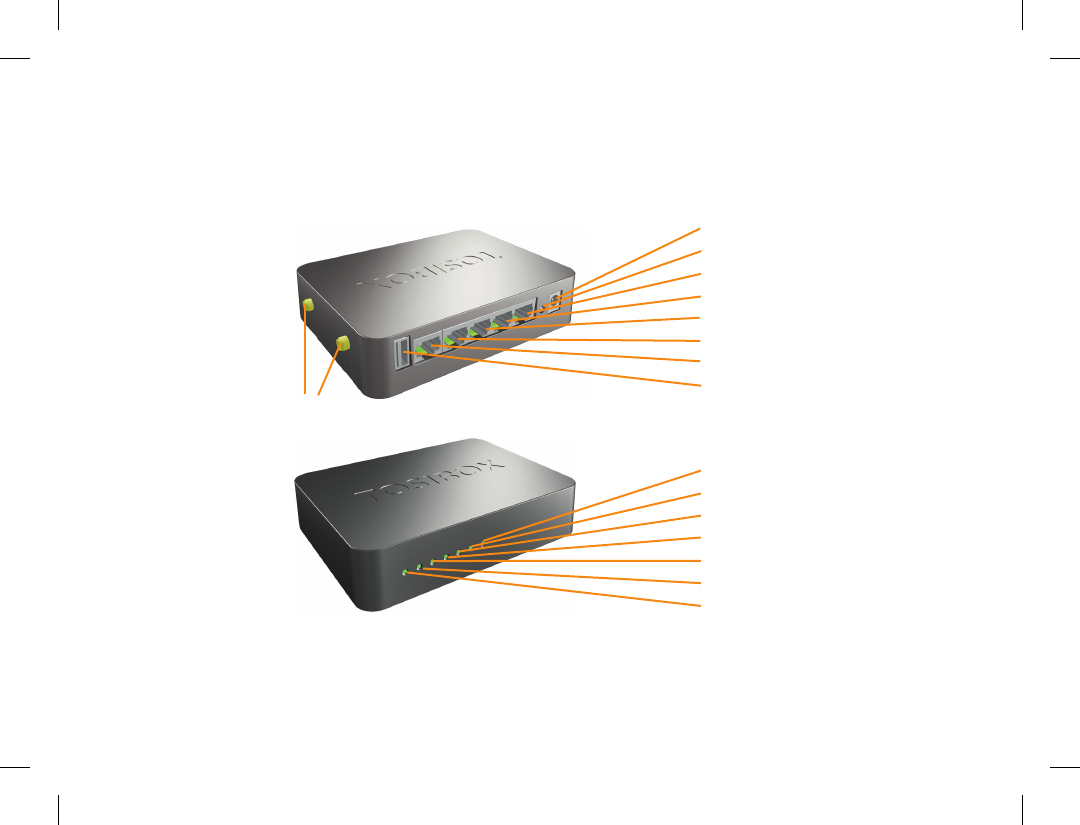
Lock connections
WLAN Antenna Ports
DC Power Input
Reset Button (Not used)
Service port
LAN3 Port
LAN2 Port
LAN1 Port
WAN Port
USB Port (for serialization
and 3G-Modem)
WAN
LAN1
LAN2
LAN3
Service
WLAN
Power

5
Tosibox glossary
Key = An intelligent USB-connected device that
contains a secure cryptoprocessor. The Key is
used to establish a secure connection to the Lock.
Sub Key = An additional Key that has restricted
access rights.
Backup Key = A duplicated backup copy of the
Key. All serializations and rights are automatically
synchronized between the original Key and the
Backup Key.
Lock = A device that accepts remote connections
from serialized Keys and creates private and
secure access to connected network devices.
The network devices that are connected to the
Lock´s LAN port are automatically found. The
Lock automatically distributes IP addresses for
the Keys, Sub Keys and the network devices
connected to LAN port(s) of the Lock. The Lock
can also control network devices with xed IP
addresses.
Sub Lock = A Lock that has been converted to
Sub Lock mode of operation. When connecting
two Locks to each other, one must be in Sub Lock
mode of operation.
DHCP-server = A network device or software
that distributes IP addresses to other devices in a
network.
Tosibox-sanastoa
Key = Älykäs, prosessorin sisältävä USB-
liitäntäinen avainlaite, jonka avulla muodostuu
yhteys lukkolaitteeseen.
Sub Key = Lisäavainlaite (Key), jonka
käyttöoikeuksia on rajoitettu ohjelmallisesti.
Backup Key = Vara-avain, Avaimesta tehty
varmuuskopio. Kaikki sarjoitukset ja oikeudet
synkronoituvat automaattisesti alkuperäisen
Avaimen ja varmuuskopion välillä.
Lock = Lukkolaite, johon etäyhteydet sarjoitetuilta
avaimilta muodostuvat ja joka tarjoaa pääsyn
ohjattaviin verkkolaitteisiin. Lukko löytää
automaattisesti kaikki sen omiin LAN-liitäntöihin
liitetyt verkkolaitteet ja Lukko myös jakaa
automaattisesti IP-osoitteet Key- ja Sub Key
-avaimille sekä Lukon omaan LANliitäntään
liitetyille verkkolaitteille. Lukolla voidaan ohjata
myös verkkolaitteita, joilla on kiinteä IP-osoite.
Sub Lock = Lukkolaite (Lock), joka on muutettu
ohjelmallisesti Sub Lock -tilaan. Yhdistettäessä
kaksi Lukkoa keskenään, toisen niistä on oltava
Sub Lock -tilassa.
DHCP-palvelin = Verkkolaite tai jonkun
verkkolaitteen ohjelmallinen osa, joka jakaa verkon
laitteille IP-osoitteet.
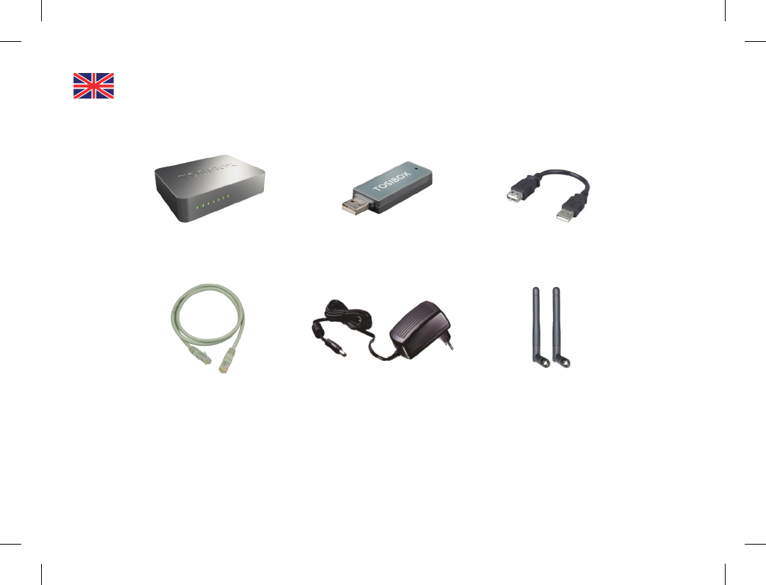
6
Tosibox Lock Tosibox Key USB Cable
Ethernet Cable AC Adapter Antennas (2)
7
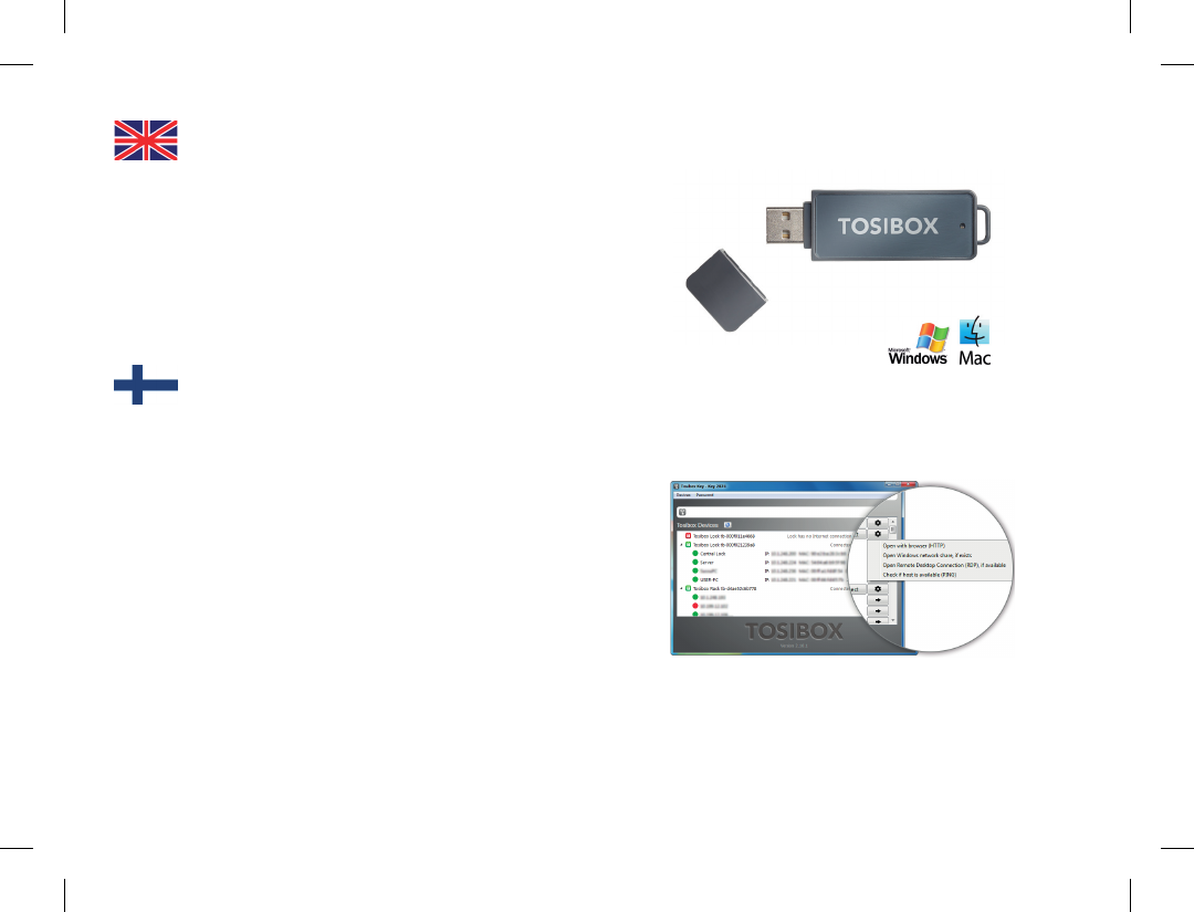
Tosibox Key
An intelligent USB-connected device that contains
a secure cryptoprocessor. The Key is used to
establish a connection with the Lock. For more
information, please see glossary (page 5).
*Key user interface (installed from the Key device).
In the image on the right you’ll notice Tosibox
Lock devices that are serialized for the Tosibox
Key and the network devices connected to them.
Tosibox Avain
Älykäs, prosessorin sisältävä USB-liitäntäinen
avainlaite, jonka avulla muodostuu yhteys
lukkolaitteeseen. Katso lisätiedot sanastosta
(sivu 5).
*Avaimen käyttöliittymä (asennetaan Avaimelta).
Kuvan vasemmassa reunassa Avaimelle sarjoitetut
Lukko-laitteet ja niihin kytketyt verkkolaitteet.
Avaa lisävalikko klikkaamalla nuolipainiketta.
Key user interface* / Avaimen käyttöliittymä*
8
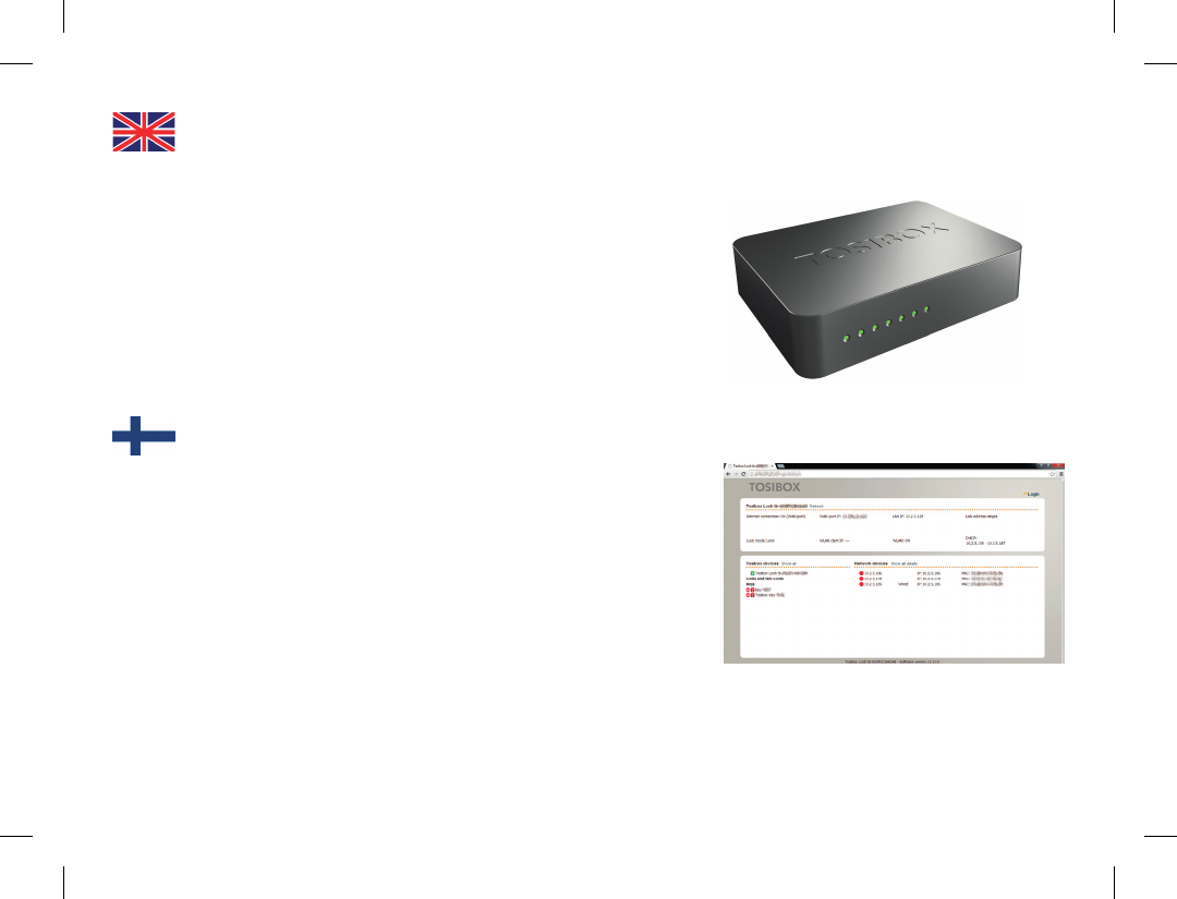
Tosibox Lock
Tosibox Lock is a device that accepts remote
connections from serialized Keys and provides
access to connected network devices. For more
information, please see glossary (page 5).
*Web user interface of the Lock. The Lock settings
can be changed via:
Service port•
Encrypted Tosibox VPN connection•
Local network•
Tosibox Lukko
Lukko on laite, johon etäyhteydet sarjoitetuilta
avaimilta muodostuvat ja joka tarjoaa pääsyn
ohjattaviin verkkolaitteisiin. Katso lisätiedot
sanastosta (sivu 5).
*Lukon selainkäyttöliittymä. Lukon asetuksia voi
muuttaa:
Service-portin kautta•
Salatun Tosibox-VPN-yhteyden kautta•
Sisäverkosta•
Web user interface for the Lock* / Lukon
verkkokäyttöliittymä*

9
Tosibox Key and
Lock serialization
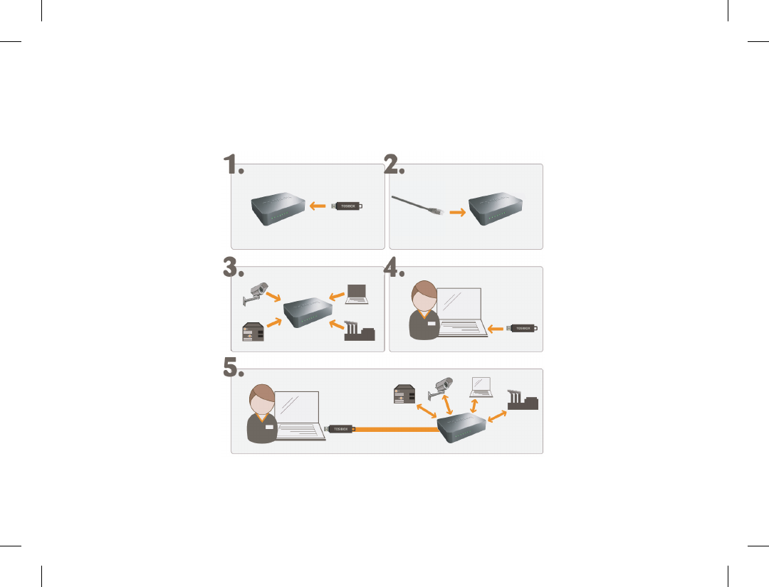
The instructions below can be further claried
by seeing the accompanying diagram on the
following page.
1. Connect the Tosibox AC adapter to the Lock
and wait for 2 minutes. Serialize the Key to
the Lock by inserting the Key into the USB
port of the Lock. When the LED on the Key
stops blinking, the serialization is complete
(approximately 10 seconds). Remove the Key
from the Lock. You can also serialize additional
Locks to the same Key. After the rst Key is
serialized to the Lock, the subsequent Keys
(Sub Keys) are serialized with a computer. See
section ”Multiple Keys, p.20”. Please see the
accompanying image on the next page.
2 - 3. Connect the Lock to your network according
to your use case. See section Deploying the
Lock (p.11.). Remember to make sure that the
Lock has a working internet connection.
4. Connect the Key to your computer and
install the Key software. Follow the section
”Deploying the Key”.
5. The Tosibox connection is now ready to be
used to control and monitor remote devices.
Avaimen (Key) ja
Lukon (Lock) sarjoitus
Allaolevat kohdat on kuvattu seuraavalla sivulla.
1. Kytke Tosibox-virtalähde Lukkoon ja odota 2
minuuttia. Sarjoita Avain Lukkoon laittamalla
Avain Lukon USB porttiin. Kun avaimen LED-
valo lakkaa vilkkumasta, sarjoitus on valmis.
Irroita Avain Lukosta. Sarjoitustapahtuman
kesto on n. 10 sekuntia. Voit sarjoittaa samalle
Avaimelle myös useampia Lukkoja. Kun
Lukkoon on sarjoitettu ensimmäinen Avain,
seuraavat Avaimet sarjoitetaan tietokoneen
avulla (Sub Key). Katso kohta ”Lisäavainten
käyttöönotto, s 20 ”
2. ja 3. Ota Lukko käyttöön. Riippuen
käyttötarpeestasi, yhdistä Lukko verkkoon
halutulla tavalla. Katso kohta ”Lukon
käyttöönotto s. 11”. Varmista että Lukko saa
toimivan internetyhteyden.
4. Liitä Avain omaan tietokoneeseesi ja asenna
Avainohjelmisto ohjeen kohdan ”Avaimen
käyttöönotto” mukaisesti.
5. Tosibox-yhteys on nyt valmis käytettäväksi. Sen
avulla voit käyttää, ohjata ja valvoa etäkohteita.
10
Tosibox Key and Lock serialization
11
Deploying the Lock
With its factory default settings, the Lock is
connected to the Internet via its WAN port or a
3G/4G modem that can be connected to the USB
port of the Lock. In this mode, the Lock creates
its own protected local network for the connected
devices. Only devices that are connected to the
Lock by cable or wirelessly are accessible with the
Key.
Notes:
See “3G modem for the Lock” (p.35) to connect a
3G or 4G modem to the Lock’s USB port.
If the Lock is connected to a DHCP enabled network via •
any of its LAN ports (LAN1, LAN2 or LAN3), the Lock’s
own LAN functionality will be lost and an error will result.
LAN functionality can be restored by resolving any DHCP
conicts by removing improper LAN connections to the
Lock.
Tosibox Lock
Connecting network devices to the Lock
A) Connecting network devices that use dynamic IP
addresses (DHCP)
Network devices with a DHCP client enabled will
automatically connect to the Lock. Simply plug them in and
go.
B) Connecting network devices with static IP addresses:
1. Assign static IP addresses to devices (from the Lock’s static IP range).
2. Go to Network > LAN and see the IP address of the Lock from ”IPv4
address”. Check also that the network mask in ”IPv4 netmask” is set
to 255.255.255.192.
3. Go to the settings of the network device. Enter an unused IP address
into the device that falls within the Lock’s static IP range. This can be
found on the default (front) page of the Lock’s web user interface.

12
4. Go to the Lock’s web user interface and click “Scan for
LAN Devices”. The Lock will automatically locate all
devices that match the Lock’s IP range.
C) Conguring a Lock’s static IP address to
match an existing network
1. Make a note of the IP address and netmask of each
controlled network device.
2. Select an unused address that falls within the IP address
range utilized by the network devices. Go to the Lock’s
settings by clicking Network > LAN. Set the Lock’s IP
address eld to “IPv4 address” and the netmask eld to
“IPv4 netmask” and leave the gateway broadcast elds
empty.
3. Go to Network > DHCP and set the “Start” value so
that it’s higher than all used static addresses. Set the
limit value to a suitable value so that it covers the rest
of the unused address in the LAN range. For example,
the range 192.168.5.50 – 192.168.5.254 contains 205
addresses so the value would be 205.

13
Connecting the Lock to an existing network in client
mode
Client mode can be used for connecting the Lock
to an existing network (e.g. an ofce network).
In this mode, the Lock joins the network like any
other device (e.g. a PC) and provides remote
users with access to other devices in the same
network. The Lock will obtain its address from
the DHCP, so the local network needs to have a
working DHCP server that allocates IP addresses.
Setting the Lock to client mode:
1. Log into the Lock’s web user interface as admin and open
the LAN settings by clicking Network > LAN.
2. Change the LAN interface protocol eld to “DHCP
client”. Click the “Switch protocol” button and click
“Save”.
3. Connect a cable from the local network to one of the
Lock’s LAN ports (e.g. LAN3).
Notice in client mode:
Do not connect the Internet to the Lock’s WAN Port or a •
3G modem to the USB port. Doing so will automatically
deactivate the client mode and revert the Lock’s LAN
settings back to factory defaults.
Do not connect any LAN port directly to the Internet.
•
Do not connect the controlled devices to the Lock’s LAN •
ports.
The Lock will scan the entire LAN network for connected
•
devices and will grant device access to any user with a
serialized Key. Please keep this in mind when considering
network and information security.
In cases where access rights need to be restricted, switch on MAC/•
IP ltering (under Industry settings) or set up the Lock in its factory
default conguration.
In this mode, the Lock’s inbuilt rewall does not protect the devices
•
in the LAN network.

14
Lukon käyttöönotto
Oletusasetuksilla Lukko kytketään internetiin
liittämällä WAN-porttiin internetyhteys tai
kytkemällä USB porttiin liitetään 3G- tai 4G-
modeemi. Tässä tilassa Lukko muodostaa oman
suojatun sisäverkon siihen liitettävistä laitteista ja
toimii sen yhdyskäytävänä internetiin. Avaimen
avulla saadaan yhteys vain näihin Lukkoon suoraan
langallisesti tai langattomasti liitettyihin laitteisiin.
Huomioitavaa:
Noudata osion ”Lukon 3G-modeemi asetukset” osion •
ohjeita kun kytket 3G- tai 4G-modeemin Lukon USB
porttiin.
Mikäli Lukko yhdistetään sen LAN- liitännästä (LAN1,
•
LAN2 tai LAN3) muuhun sisäverkkoon, jossa on jo
toimiva DHCP-palvelu, , Lukon oma LAN-verkko lakkaa
toimimasta. Lukon oma LAN-verkko palautuu toimivaksi,
kun väärä kytkentä poistetaan.
Ohjattavien verkkolaitteiden liittäminen
Lukkoon
A) Vaihtuvalla IP-osoitteella varustettujen
laitteiden käyttöönotto:
Mikäli kaikki ohjattavat laitteet toimivat
vaihtuvalla IP-osoitteella, ne yhdistyvät Lukkoon
automaattisesti. Tässä tapauksessa LAN-verkko
muodostuu Plug & Go -periaatteella.
B) Kiinteällä IP-osoitteella varustettujen laitteiden
käyttöönotto:
1. Liitä tietokone Lukon service-porttiin. Kirjoita internetselaimeen
“http://service.tosibox” tai “http://172.17.17.17”. Käyttäjätunnus on
“admin” ja salasana on nähtävissä Lukon pohjassa.
2. Mene kohtaan Network > LAN ja tarkista Lukon IP-osoite kohdasta
“IPv4 address”. Tarkista lisäksi että verkkomaskiksi kohdassa “IPv4
netmask” on asetettu 255.255.255.192.
3. Mene ohjattavan laitteen asetuksiin. Aseta laite samaan
osoiteavaruuteen kuin Lukon LAN siten, että ohjattavan laitteen
IP-osoitteen neljäs (viimeinen) luku on Lukon IP-osoitteesta 1–9
seuraavaa ylöspäin. Aseta vielä verkkomaskiksi 255.255.255.192. –
Esimerkki: Lukon LANosoite on 10.25.15.193, tällöin ensimmäisen
ohjattavan laitteen IP-osoite on 10.25.15.194 ja seuraava
10.25.15.195 jne.
4. Mene Lukon selainkäyttöliittymään asetuksiin ja valitse ”Scan for LAN
devices” -toiminto, jolloin Lukko löytää saman verkkoavaruuden
laitteet automaattisesti muutamassa minuutissa. Voit myös asettaa
ohjattavan laitteen IP-osoitteen (esim. 10.25.15.194) manuaalisesti
Lukon käyttöliittymään ”New network device” -toiminnolla.
Halutessasi voit myös nimetä laitteen uudelleen.

15
C) Kiinteällä IP-osoitteella varustettujen laitteiden
käyttöönotto käyttäen niiden nykyisiä osoitteita
1. Selvitä ohjattavien laitteiden IP-osoitteet ja verkkomaski. Tämä
esimerkki olettaa osoitteeksi 192.168.5.20 ja verkkomaskiksi
255.255.255.0.
2. Valitse Lukolle käyttämätön osoite LAN-osoiteavaruudesta (joka
on tässä tapauksessa 192.168.5.1 – 192.168.5.254). Mene Lukon
asetuksiin osioon Network > LAN ja aseta Lukon IP-osoite (esim.
192.168.5.1) kenttään ”IPv4 address” ja verkkomaski (tässä
tapauksessa 255.255.255.0) kenttään “IPv4 netmask”. Jätä gateway-
ja broadcast-kentät tyhjiksi.
3. Mene valikkoon Network -> DHCP ja aseta “Start”-arvo siten että
se on suurempi kuin Lukolla ja laitteilla käytössä olevat staattiset IP-
osoitteet (esim. 50). Mikäli “Limit”- arvoa on tarvetta muuttaa, aseta
se sopivasti siten että se kattaa loput LAN-osoiteavaruudesta (esim.
192.168.5.50 – 192.168.5.254 käsittää 205 osoitetta joten arvoksi
tulisi 205).
Lukon liittäminen olemassa olevaan verkkoon client-
tilassa
Client-tilaa voi käyttää esim. pienyrityksen toimistoon
etäyhtäyden muodostamista varten. Tässä tilassa Lukko on
yksi sisäverkon laitteista (kuten PC) ja tarjoaa etäkäyttäjille
automaattisesti pääsyn haluttuihin muihin saman verkon
laitteisiin. Client-tilassa Lukko hakee IP-osoitteensa
automaattisesti, jolloin sisäverkossa täytyy olla IP-osoitteet
jakava toimiva DHCP-palvelin.
Lukon client-toimintatilan käyttöönotto:
1. Kirjaudu sisään Lukon selainkäyttöliittymään adminkäyttäjänä ja avaa
asetuksista Network > LAN.
2. Vaihda LAN-liitännän protokollaksi “DHCP client”, valitse “Switch
protocol” ja paina lopuksi “Save”.
3. Kytke sisäverkon Ethernet-kaapeli johonkin Lukon LANporteista
(esim. LAN3).
Huomioitavaa client-tilassa:
Älä kytke verkkojohtoa Lukon WAN-porttiin tai 3G-modeemia USB •
porttiin, koska tällöin Lukko poistuu client-tilasta ja LAN-asetukset
palautuvat oletusarvoihinsa.
LAN-porttia ei saa kytkeä suoraan internetliittymään.
•
Älä kytke ohjattavia laitteita Lukon LAN-portteihin.•
Lukko skannaa koko sisäverkon löytääkseen hallittavat laitteet ja •
Avaimen käyttäjällä on oletuksena pääsy kaikkiin sisäverkon laitteisiin.
Huomioi tietoturva.
Mikäli käyttöoikeutta täytyy rajoittaa, ota käyttöön MAC tai IP-
•
suodatus (industry-asetus) tai ota Lukko käyttöön oletustilassaan (ks.
kappale “Lukon käyttöönotto”).
Tässä tilassa Lukon sisäänrakennettu palomuuri ei suojaa sisäverkon
•
laitteita.
16
1. Deploying the Key 3. Key user interface
2. Setting the password

17
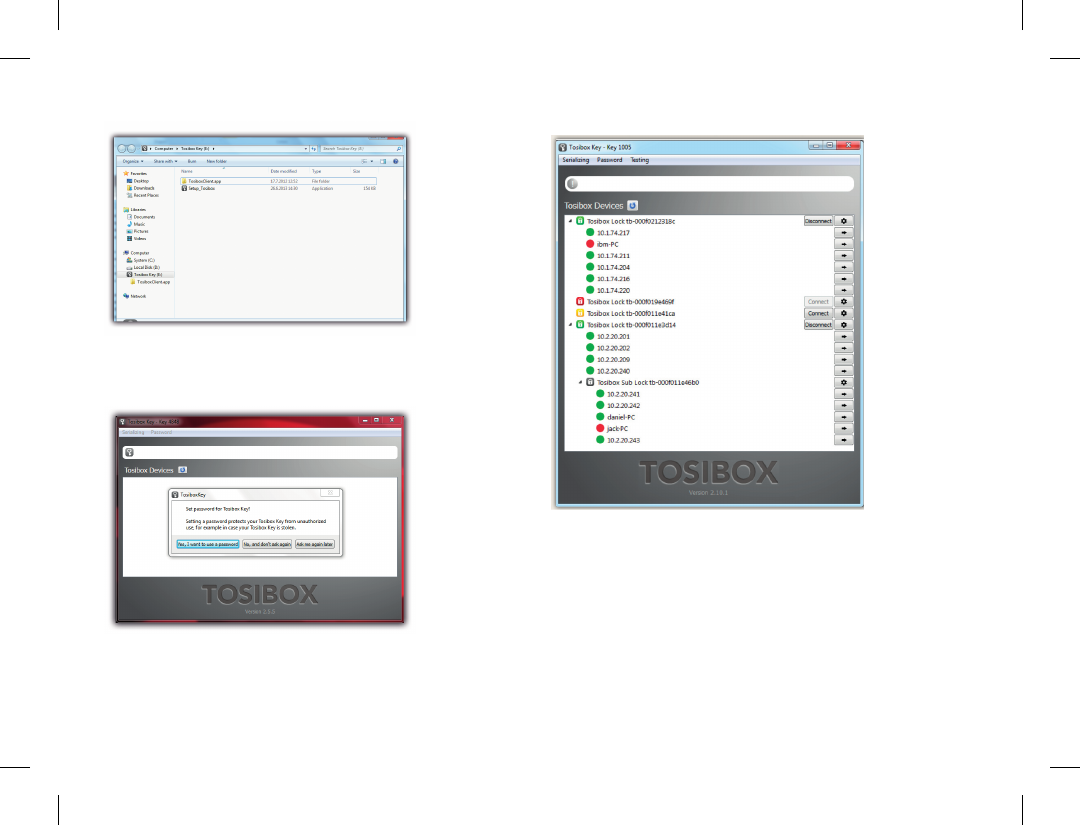
Deploying the Key
1. Insert the serialized Key into the USB port of your
computer. You should notice an auto play window open
up on your desktop. If not, double click the executable
le located in the Key’s folder (Setup_Tosibox.exe). If
your computer asks whether you want to allow Tosibox to
make changes to your computer click yes.
2. The Key software will ask for a password that you can
enter if you wish (recommended). By entering a password,
you can prevent the unauthorized use of the Key. Store
the password safely.
3. The Key software opens up a window that shows the
Locks that have been serialized to the Key. Connect
the Key with the wanted Lock by clicking the Lock’s
“Connect” icon.
4. The Key info dialogue shows the status of the connection
between the Key and Lock.
The Key is now ready to be used
The Lock symbol displays a different colour
according to the operating status of the Lock:
Red = Lock is not connected to the Internet.•
Yellow = The Lock and Key have detected each other but •
a connection has yet to be established.
Green = An encrypted connection has been established
•
between the Lock and Key.
The Key symbol located in the computer’s task
bar displays different colours according to the
operating status of the Key:
Red = The Key is not connected to the Internet.•
Yellow = The Key is connected to the Internet, but not to •
any found Locks.
Green = The Key is connected to at least one Lock.
•
Avaimen käyttöönotto
1. Aseta sarjoitettu Avain tietokoneen USB porttiin.
Käynnistä työpöydälle avautuvasta “Autoplay” -ikkunasta
“Setup_Tosibox” -niminen suoritustiedosto. Jos
tietokoneesi kysyy sallitko Tosiboxin tehdä muutoksia >
klikkaa salli. Avaimen asennus käynnistyy. Asennuksen
jälkeen sulje asennusikkuna valitsemalla ”close”.
2. Avain kysyy salasanan, jonka voit tässä vaiheessa syöttää
(suositus). Asettamalla salasanan voit estää Avaimen
luvattoman käytön. Talleta salasana huolella.
3. Avain aukaisee ikkunan, jossa näkyvät Avaimelle sarjoitetut
Lukot. Yhdistä Avain haluamaasi Lukkoon klikkaamalla
kyseisen Lukon connect-painiketta.
4. Seuraavaksi Avaimen info-laatikossa näkyy tieto kuinka
Avain muodostaa yhteyden Lukkoon.
Avaimen käyttöönotto on valmis.
Lukkosymboli näkyy ikkunassa eri värillä
riippuen lukon toimintatilasta:
Punainen = Lukko ei ole yhteydessä internetiin.•
Keltainen = Lukko ja Avain ovat tunnistaneet toisensa, •
mutta Avaimen ja Lukon välinen yhteys on vielä
muodostumatta.
Vihreä = Avaimen ja Lukon välinen salattu yhteys on
•
muodostunut.
Avainsymboli näkyy tietokoneen tehtäväpalkissa
eri värillä riippuen avaimen toimintatilasta:
Punainen = Avain ei ole saanut yhteyttä internetiin.•
Keltainen = Avain on saanut yhteyden internetiin ja •
löytänyt ainakin yhden Lukon, mutta Avaimen yhteys
yhteenkään Lukkoon ei ole vielä muodostunut.
Vihreä = Avaimen salattu yhteys ainakin yhteen Lukkoon
•
on muodostunut.
18
Key user interface
Picture 1.
Picture 2.
Picture 3.
Double click to open
Lock user interface

19
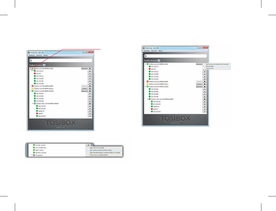
Renaming and using devices
Picture 1.
This is the start window for the Key user interface.
You can open the Lock user interface by double
clicking the Lock icon on the left side of the
window.
Picture 2.
By clicking an extra menu opens.
1. Click “Open browser automatically when connected” to
have the Lock user interface launch automatically when
the Key connects to the Lock.
2. Selecting “Show all details” allows you to view all the
details of the connected device.
3. Click “Rename device” to rename the selected device.
Lock names are Key specic, so a Lock’s name change will
be reected only with the Key that was used to change it.
Picture 3.
1. You can open the browser user interface of the controlled
device in “Open with browser (http)”.
2. You can connect to network sharing in “Open windows
network share”.
3. You can open the remote desktop connection in “Open
Remote Desktop Connection (RDP), if available”.
4. You can check the functionality of the controlled device
with PING command in “Check if host available (PING)”.
Laitteiden nimeäminen ja
käyttäminen
Kuva 1.
Avaimen käyttöliittymän alkunäkymä. Lukon
käyttöliittymä aukeaa oletusselaimeen
tuplaklikkaamalla Lukko-kuvaketta.
Kuva 2.
Klikkaamalla avautuu lisävalikko.
1. Voit valita Lukon oletusselaimen aukeamaan
automaattisesti Avaimen käyttöliittymän kohdasta “Open
browser automatically when connected.
2. Näet laitteiden lisätiedot klikkaamalla: “Show all details”.
3. Voit nimetä Lukon klikkaamalla ”Rename device”.
Huomioi että nimeäminen näkyy vain tälle kyseiselle
Avaimelle.
Kuva 3.
1. “Open with browser (http)” -kohdasta voit avata
ohjattavan laitteen selainkäyttöliittymän.
2. “Open windows Network Share, if exists” -kohdasta voit
yhdistää palvelimen verkkojakoon.
3. “Open Remote Desktop Connection (RDP), if available”
-kohdasta voit ottaa käyttöön etätyöpöytäyhteyden.
4. “Check if host available (PING)” -kohdasta voit tarkistaa
laitteen yhteyden toimivuuden PINGkomentokehotteella.
20
Multiple Keys / Lisäavainten käyttöönotto
Picture 1. Picture 2.
Picture 3. Picture 4.

21
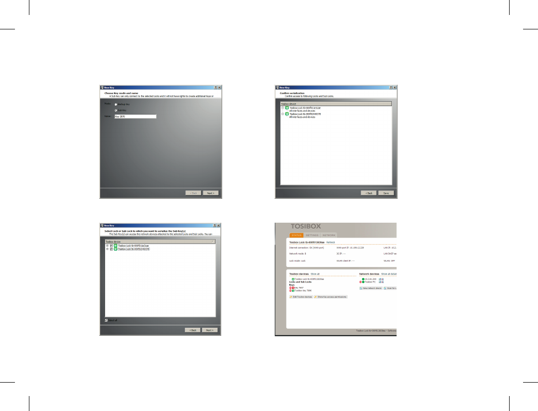
Multiple Keys
Additional Keys can be serialized to a Lock.
1. Insert a previously serialized Key into the USB of your
computer.
2. Insert a new Key to another USB port of the computer.
Picture 1.
3. Wait until ”New Key” window opens.
4. When a new Key is turned into a Sub Key, choose ”Sub
Key”, provide a descriptive name for it, and click ”Next”.
A Sub Key is able to connect to chosen Locks but it has no
rights to serialize new Keys. Picture 2.
5. Select the Lock(s)/Sub Lock(s) to which you want to
serialize the extra Key and choose ”Next”. Picture 3.
6. Conrm the selection by pressing ”Save”. Serialization for
the extra Key is now complete. Picture 4.
7. Serializations of additional keys can be removed in the
Lock user interface by clicking “Edit Tosibox devices”
(admin only).
Lisäavainten käyttöönotto
Voit sarjoittaa Lukkoon tarvitsemasi määrän
lisäavaimia. Tätä ennen tulee olemassa oleva Avain
olla sarjoitettu vähintään yhteen Lukkoon.
1. Aseta Lukossa sarjoitettu Avain tietokoneen USB porttiin.
2. Aseta uusi Avain tietokoneen toiseen USB porttiin. Kts.
kuva 1.
3. Odota kunnes “New Key” -ikkuna aukeaa.
4. Kun uudesta avaimesta tehdään Sub Key, valitse “Sub
Key”, anna avaimelle haluamasi nimi ja klikkaa “Next”.
Sub Keyllä voi muodostaa yhteyden Lukkoon, mutta sillä
ei ole oikeutta sarjoittaa uusia Avaimia. Kts. Kuva 2.
5. Valitse Lukko/Lukot (Lock tai Sub Lock), johon haluat
sarjoittaa lisäavaimen ja valitse “Next”. Kts. kuva 3.
6. Vahvista valinta painamalla “Save”. Lisäavaimen sarjoitus
on nyt valmis. Kts. kuva 4.
7. Lisäavaimen sarjoituksen voi poistaa admin-tunnuksella
Lukon käyttöliittymän toiminnolla “Edit Tosibox devices”.
22
Extra Key use case / Lisäavaimen käyttöesimerkki

23
Adding additional Locks to
a serialized Key
This feature is only available for Keys that have
already been serialized locally.
1. Insert the Key into the USB port of the computer and wait
for the Tosibox Key application to start.
2. Choose ”Manage Keys” from the “Devices” menu in the
user interface and open the “Sub Keys” tab.
3. Choose the extra Keys to which you want to serialize new
Locks and press the ”Serialize...” button.
4. Choose the Locks to which you want to serialize the extra
Keys and press the ”Next” button.
5. A list of targeted Locks is displayed. Conrm serialization
and click “Save”.
6. Serialization of the extra Keys is now complete. Press
“Finish” button to exit the wizard.
Lisäavainten etäsarjoitus
Tämä toiminto vaatii, että olet sarjoittanut
halutut lisäavaimet ensin paikallisesti omassa
tietokoneessasi.
1. Aseta Avain tietokoneen USB porttiin ja odota, kunnes
Tosibox Key -sovellus käynnistyy.
2. Käynnistä “Manage Keys” -toiminto käyttöliittymän
“Devices”-valikosta ja valitse “Sub Keys” -välilehti.
3. Valitse lisäavaimet, joille haluat sarjoittaa uusia lukkoja, ja
paina “Serialize...”-painiketta.
4. Valitse seuraavaksi ne Lukot, joihin haluat lisäavaimet
sarjoittaa, ja paina sen jälkeen “Next”-painiketta.
5. Seuraavaksi näytetään lista niistä lukoista, joihin
lisäavaimet sarjoitetaan. Varmistettuasi, että olet
sarjoittamassa lisäavaimia oikeisiin lukkoihin, paina “Save”-
painiketta.
6. Lisäavainten sarjoitus on nyt valmis. Paina “Finish”-
painiketta poistuaksesi toiminnosta.
24
Creating a Backup Key / Vara-avaimen luonti
Picture 1. Picture 2.
Picture 3. Picture 4.

25
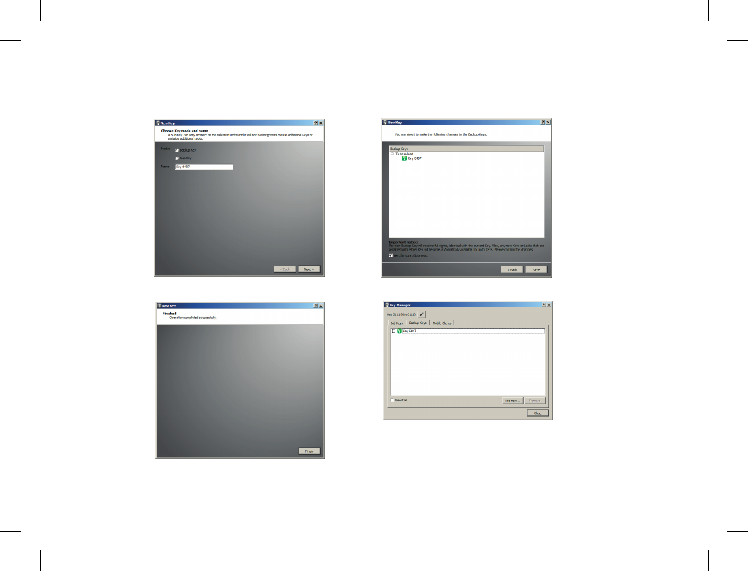
Creating a Backup Key
A duplicate can be made from a Key that has
been serialized to a Lock. This duplicate can act
as a Backup Key, for example.
1. Insert the Key into the USB port of the computer.
2. Insert a new Key into another USB port of the computer.
Picture 1.
3. Wait until the ”New Key” window opens.
4. Choose ”Backup Key” and press ”Next”. All serializations
and user rights are automatically synchronized between
the Backup Keys. Picture 2.
5. Conrm by pressing ”Save”. Picture 3.
6. The Backup Key is now created. Press ”Finish” button to
exit the feature. Picture 4.
7. The Backup Keys can be managed later in the Key user
interface under ”Manage Keys”. Important: This feature
creates a Backup Key with equal user rights. Later, when
the new locations are deployed by the other Key, the
access rights are automatically copied to both Keys.
Vara-avaimen luonti
Lukkoon sarjoitetusta Avaimesta on
mahdollista luoda myös Vara-avain, esimerkiksi
varmuuskopioksi.
1. Aseta Lukossa sarjoitettu Avain tietokoneen USB porttiin.
2. Aseta uusi Avain tietokoneen toiseen USB porttiin. Kts.
kuva 1.
3. Odota kunnes “New Key” -ikkuna aukeaa.
4. Kun uudesta Avaimesta tehdään Vara-avain, valitse
“Backup Key” ja paina “Next”. Kaikki sarjoitukset ja
oikeudet synkronoituvat automaattisesti Vara-avainten
välillä. Kts. kuva 2.
5. Vahvista toimenpide painamalla “Save”. Kts. kuva 3.
6. Vara-avain on nyt luotu. Paina “Finish”-painiketta
poistuaksesi toiminnosta. Kts. kuva 4.
7. Voit myöhemmin hallita Vara-avaimia Avaimen
käyttöliittymän toiminnolla “Manage Keys”. Tärkeää
huomioida: Tämä valinta antaa uudelle Vara-avaimelle
yhtäläiset oikeudet. Jatkossa myös kaikkiin uusiin
kohteisiin, mitkä otetaan käyttöön vain toisen avaimen
toimesta, kopioituu pääsyoikeus AUTOMAATTISESTI
kummallekin avaimelle!
26
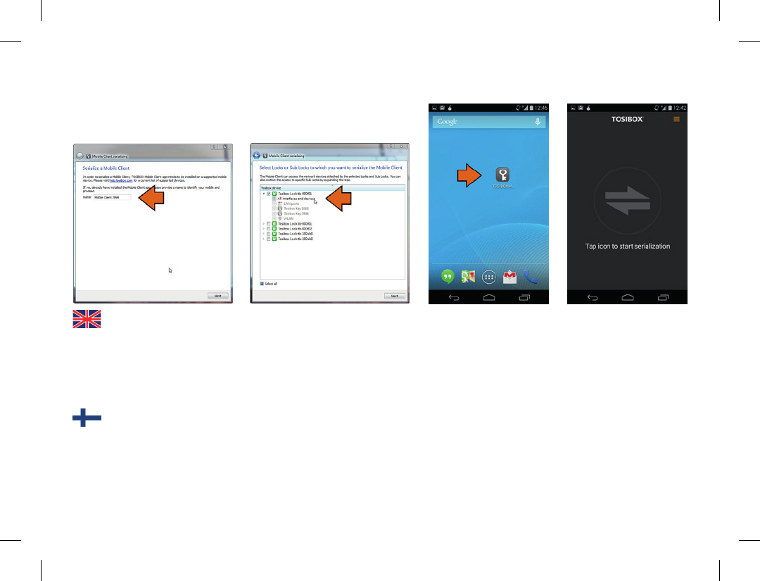
Using the Mobile Client Mobile Clientin käyttäminen
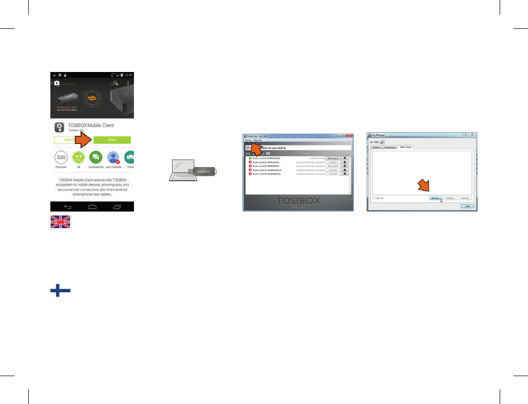
2. Open the Tosibox Key
software by plugging
a serialized Key into
the USB port of your
computer.
3. Go the software menu and
select Devices > Manage
Keys.
4. Select the mobile clients tab and
click Add new...
1. Download and install
the Tosibox mobile
client from the Google
Play store.
2. Avaa Tosibox Key
-ohjelma asettamalla
sarjoitettu Avain
tietokoneesi USB-
porttiin.
3. Mene ohjelman valikkoon ja
valitse Devices > Manage
Keys.
4. Valitse Mobile Clients ja klikkaa
Add new…
1. Lataa ja asenna
Tosibox mobile
client Google Play
verkkokaupasta.
27
5. Enter the name of your mobile
device and click Next.
6. Select the Locks that you would
like to access through your
mobile device and click Next.
7. Open the Tosibox
mobile client on your
device.
8. Tap the screen to start
serialization.
5. Anna nimi mobiililaitteellesi ja
klikkaa Next.
6. Valitse Lukot joihin haluat
muodostaa yhteyden
mobiililaitteellasi ja klikkaa
Next.
7. Avaa Tosibox Mobile
Client laitteessasi.
8. Kosketa ruutua
aloittaaksesi
sarjoituksen.
28
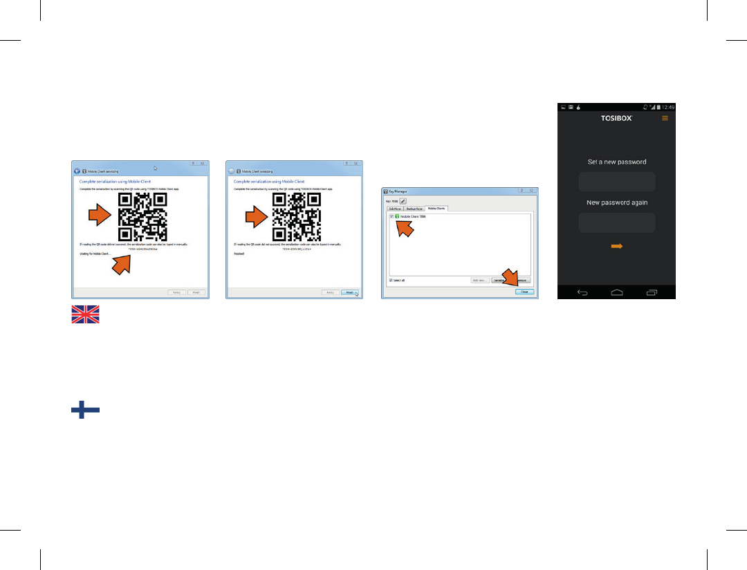
11. Make sure your device is
checked and close the Key
manager window.
12. Create a password for
the mobile client.
9. Scan the QR code
displayed on your
computer or enter the
serialization code where
prompted on your device.
10. Click Finish once the the
serialization is complete.
11. Tarkista että laitteesi on
valittuna ja klikkaa Close.
9. Kuvaa tietokoneen
ruudulla näkyvä QR-koodi
laitteen kameralla tai syötä
sarjoituskoodi laitteelle.
10. Klikkaa Finish kun sarjoitus
on valmis.
12. Luo Mobile Clientille
salasana ja klikkaa
oranssia nuolta.
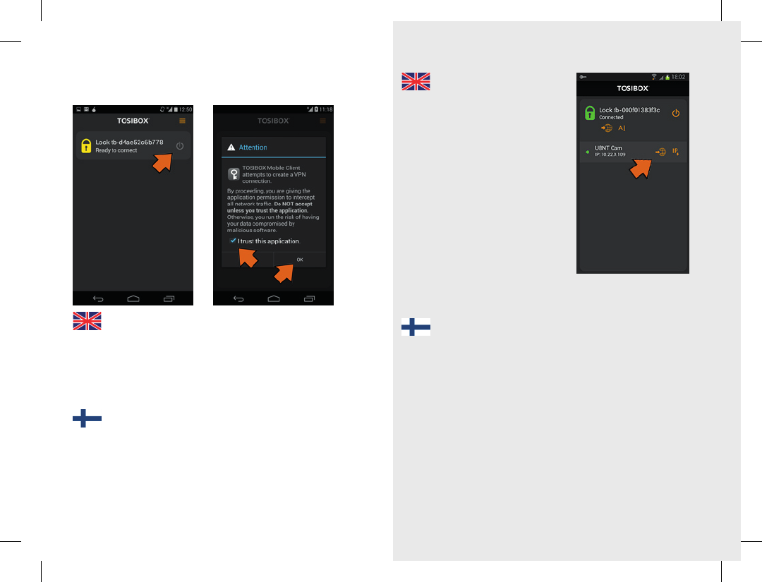
29
13. Connect to a Lock by
selecting its on/off
icon.
14. Check the I trust this
application dialogue
box and click OK.
13. Yhdistä Lukko
valitsemalla on/off
-ikonista.
14. Valitse I trust this
application ja klikkaa
OK.
Congratulations! You’re done! Now
your mobile client is serialized and
can connect to the selected Locks and
devices connected to them.
You can open network devices through
your web browser (if available) by
clicking the the appropriate globe
icon. Note: If your network device
does not have a web interface (HTTP
/ HTTPS), you can use a third party
application to make the connection.
You can nd third party applications
from the Google Play store. You can
copy the network device IP address to
the device’s clipboard by clicking the
IP button. Doing so will allow you to
paste the IP address to a third party application.
Nyt Mobile Clientisi on sarjoitettu ja sillä voidaan ottaa yhteys
valittuihin Lukkoihin ja niihin kytkettyihin laitteisiin.
Voit avata yhteyden verkkolaitteisiin verkkoselaimesi (jos
käytettävissä) kautta klikkaamalla asiaankuuluvaa maapallonkuvaa.
Huomaa: jos verkkolaitteessasi ei ole verkkoliitäntää (HTTP /
HTTPS), voit käyttää kolmannen osapuolen sovellusta yhteyden
muodostamiseen. Kolmannen osapuolen sovelluksia löytyy Google
Play -verkkokaupasta. Voit kopioida verkkolaitteen IP-osoitteen
mobiililaitteesi leikepöydälle klikkaamalla IP-painiketta. Tällä tavoin
voit antaa IP-osoitteen kolmannen osapuolen sovellukseen.
30
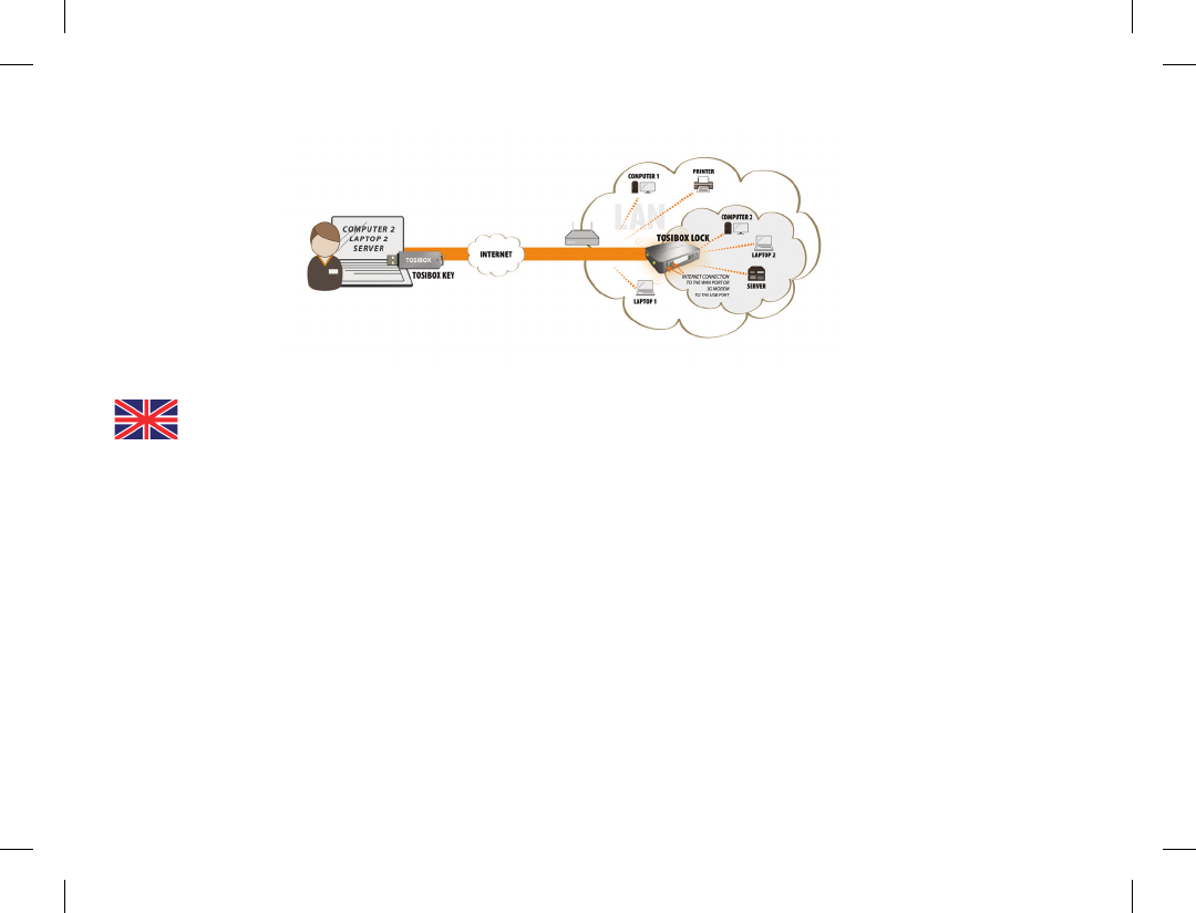
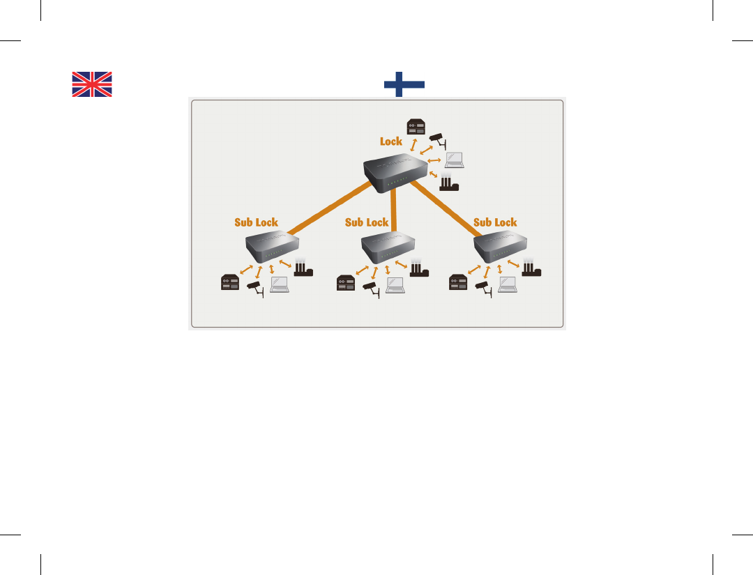
Connecting Locks
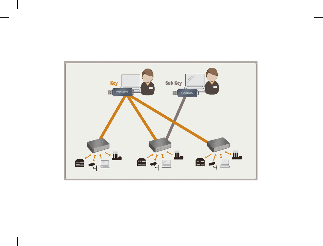
Connecting Locks
With Tosibox Locks one can connect machines in
separate places so that the connection between them is
permanently and automatically on. One example is a real-
time protected connection between home and ofce. This
is made with a Lock/Sub Lock solution (see accompanying
image Connecting Locks). Up to 10 Sub Locks can be
connected to one Lock.
First serialize the Key to all the Locks to be connected as
described in section “Tosibox Lock and Key serialization”.
Lukkojen yhdistäminen
Tosibox Lukoilla voidaan yhdistää myös pysyvästi kaksi
tai useampia eri nettiosoitteissa tai maantieteellisesti eri
alueilla sijaitsevaa kiinteää kohdetta toisiinsa siten, että
yhteys niiden välillä on kokoaikaisesti ja automaattisesti
aina päällä. Tällainen yhteys on esimerkiksi jatkuvaaikainen
kodin ja konttorin välinen suojattu yhteys. Tämä toteutetaan
“Lock - Sub Lock” -yhdistelmällä (ks. kuva). Yhteen Lukkoon
voidaan liittää jopa 10 Sub Lockia.
Sarjoita aluksi Avain kaikkiin yhdistettäviin Lukkoihin
kohdan “Avaimen ja Lukon sarjoitus” -ohjeiden mukaisesti.
Lukkojen yhdistäminen

31
1. Aseta sarjoitettu Avain tietokoneen USB porttiin.
2. Valitse Avain käyttövalikosta “Devices” ja alasvetovalikosta
“Serialize Locks”.
3. Valitse Lukot, jotka haluat sarjoittaa yhteen ja valitse
”Next”.
4. Valitse Lukko, johon liität Sub Lockit. Muut Lukot vaihtuvat
Sub Lock -toimintatilaan.
5. Vahvista valinta > Save > Sarjoitus on valmis.
Huom! Sarjoitukset tulevat voimaan vasta kun
Lukot ovat internetyhteydessä.
Kuvan Sub Lock -yhteyspäissä ei ole omaa DHCP
-palvelua. Mikäli yhteys Lockin ja Sub Lockin välillä
katkeaa, eivät Sub Lockiin kytketyt verkkolaitteet
saa enää yhteyttä internetiin eivätkä toisiinsa.
1. Insert a serialized Key to the USB port of the computer.
2. Choose ”Devices” from the Key user menu and ”Serialize
Locks” from the drop down menu.
3. Choose the Locks that you want to serialize together and
choose ”Next”.
4. Choose the Lock that you want to attach the Sub Locks.
The other Locks will be changed to Sub Lock operating
mode.
5. Conrm the selection > Save > serializing is ready.
Note: The serializations will come into effect when
the Locks have access to the Internet.
The Sub Lock ends of the connection in the
picture do not have their own DHCP service. If the
connection between the Lock and the Sub Lock
is interrupted, the network devices connected
with the Sub Lock can no longer connect to the
Internet and each other.
Logging in to the Lock
The Lock has two user accounts with different
access levels, user and admin. The usernames
and the passwords are printed on the bottom of
the Lock. The user account has a limited set of
rights to make changes.The Lock’s settings can
be changed remotely with the Key or locally by
connecting the PC directly to Lock’s service port
through an ethernet cable.
Log into the Lock using admin or user as the
username. When logging in directly from the
service port of the Lock the address is ”http://
Lukkoon kirjautuminen
Lukossa on kaksi käyttäjäoikeustasoa, user ja
admin. käyttäjätunnukset ja salasanat ovat
nähtävissä Lukon pohjassa. User-käyttäjällä on
rajoitetummat oikeudet tehdä muutoksia. Lukon
asetuksia pääsee muuttamaan sekä etäältä
Avaimen avulla että yhdistämällä PC suoraan
ethernet-kaapelilla Lukon service-porttiin.
Kirjaudu sisään Lukkoon käyttäen admin -tai
user-tunnusta. Kirjauduttaessa suoraan Lukon
service-portista osoite on ”http://service.tosibox”

32
service.tosibox” or ”http://172.17.17.17”.
When logging in from the ”LAN” ports (1, 2 or
3) the address is ”http://service. Tosibox” (Not
functional in client mode).
The user account has the following rights:
Adding new controlled devices•
Renaming the controlled devices•
Removing of controlled devices•
Software update download•
Rebooting•
Changing the user password•
The admin account has the following rights:
All user level rights
•
Changing the admin password•
Scanning the network devices•
Renaming the Key and Lock connections•
Removing the Key and Lock connections•
Removing the serializations•
Allowing/disallowing the automatic software updates•
Changing the operating mode (Lock - Sub Lock)•
Wireless settings (WLAN)•
Settings of LAN and WAN connections (e.g. DHCP •
settings, own static IP addresses of the Lock, setting the
static routes)
3G settings
•
Industry settings•
MAC ltering•
Internet connection priority settings•
Wireless client connection setting•
tai ”http://172.17.17.17”. Kirjauduttaessa LAN-
porteista (1, 2 tai 3) osoite on ”http://service.
tosibox”(ei toimi Client-tilassa).
User-tunnuksella on seuraavat oikeudet:
Ohjattavien laitteiden lisääminen•
Ohjattavien laitteiden nimeäminen•
Ohjattavien laitteiden poistaminen•
Ohjelmistopäivityksen hakeminen•
Lukkolaitteen uudelleenkäynnistys•
User-käyttäjän salasanan vaihtaminen•
Admin-tunnuksella on seuraavat oikeudet:
Kaikki user-tunnuksen oikeudet
•
Admin -käyttäjän salasanan vaihtaminen•
Verkkolaitteiden skannaustoiminto•
Avain- ja Lukko -yhteyksien uudelleen nimeäminen•
Avain- ja Lukko -yhteyksien poistaminen•
Sarjoitusten poistaminen•
Automaattisten ohjelmistopäivitysten salliminen/•
estäminen
Toimintamoodin vaihto (Lock - Sub Lock)
•
Langattoman verkon asetukset (WLAN)•
LAN- ja WAN-liitynnän verkkoasetukset (mm. DHCP •
asetukset, laitteen omat kiinteät IP-osoitteet ja kiinteän
reitin määrittäminen)
3G-asetukset
•
Industry-suojausasetukset•
MAC-suodatustoiminto•
Internetyhteyksien priorisointiasetukset•
Wireless Client-liitäntäasetus•
33
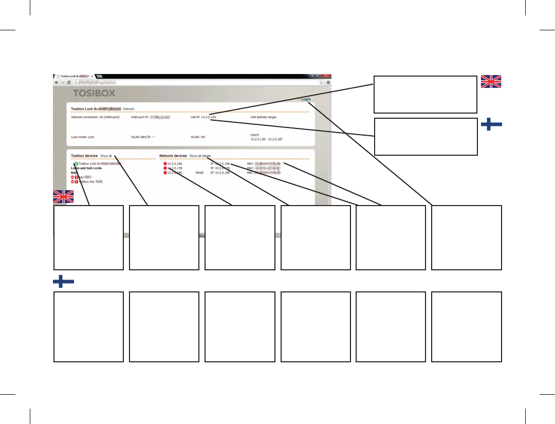
User Interface – Lock
Status window indicates the
Lock mode of operation
Statusikkuna kertoo Lukon
toimintatilan
Locks and Keys
Green: Connection
is ready
Red: Lock not found
Additional
information for the
Keys and Locks
Remotely controlled
devices
Green: Connection
is ready
Red: No connection
Details of the
remotely controlled
devices
Additional
information for
the remotely
controlled devices
IP-addresses and
MAC addresses
Login using User
or Admin
passwords found
on the bottom of
the Lock
Lukot ja Avaimet,
Vihreä valo = yhteys
on
Punainen valo =
yhteys off
Klikkaamalla
näet Avainten ja
Lukkojen lisätiedot
Ohjattavat laitteet,
Vihreä valo = yhteys
on
Punainen valo =
yhteys off
Klikkaamalla
näet ohjattavien
laitteiden lisätiedot
Lisätiedot
ohjattavista
laitteista:
laitteiden
IP-osoitteet ja
laitteiden
Klikkaamalla
pääset
kirjautumaan
User- tai
admintunnuksilla.
Tunnukset ovat
Lukon pohjassa

34
Updating the software
1. Connect the computer to the service port of the Lock with
an ethernet cable. First check that you have access to the
Internet via the service port. Open an internet browser
and type http://172.17.17.17 or http://service.tosibox into
the address eld to access the Lock user interface. Do not
type “www” before the “http://” in either address.
Alternatively you can also log in remotely using the
“admin” user ID. When the connection between the Key
and the Lock is active, double click the Lock symbol in the
Key user interface. Log in using “admin” for the user ID.
The password is visible on the bottom of the Lock.
2. Choose ”settings” > ”software update” > ”Start software
update”.
3. Wait until the software has downloaded. Do not interrupt
the power of the Lock during the software update
process. The update is complete when the software gives
a notice ”Software updated successfully”.
Automatic software updates are activated as a
default setting. You can select the time when
the automatic update of the released software
is allowed. You can deactivate the automatic
software update from the Lock user interface.
Choose “settings” > “software update” >
uncheck the box “auto update enable”.
Ohjelmiston päivitys
1. Liitä tietokone Lukon Service -porttiin ethernetkaapelilla.
Varmista aluksi, että pääset tietokoneella internettiin
Service-portin kautta. Avaa internetselain. Kirjoita
osoitekenttään: http://172.17.17.17 tai http://service.
tosibox päästäksesi Lukon käyttöliittymään.
Älä käytä www-etuliitettä. Vaihtoehtoisesti voit kirjautua
myös etäältä Lukkoon Avaimen avulla. Avaimen ja Lukon
välisen yhteyden ollessa päällä tuplaklikkaa avaimen
käyttöliittymässä Lukon symbolia. Kirjaudu sisään käyttäen
“admin” -käyttäjätunnusta, salasana on nähtävissä Lukon
pohjassa.
2. Valitse “settings” > “Software update” > “Start Software
update”.
3. Odota että ohjelmisto latautuu. Älä katkaise Lukon virtaa
ohjelmistopäivityksen aikana. Päivitys on valmis kun
ohjelmisto ilmoittaa “Software updated successfully”.
Oletusasetuksena automaattinen ohjelmiston
päivitys on aktivoituna. Voit valita kellonajan jolloin
mahdollinen julkaisuun tuleva ohjelmistopäivitys
saa asentua automaattisesti. Voit halutessasi
asettaa automaattisen ohjelmiston päivityksen
ei-aktiiviseksi Lukon käyttöliittymästä. Valitse
“settings” > “software update” -> poista ruksi
kohdasta “auto update enable”.

35
3G settings for the Lock
You can connect the Lock to the Internet with
a 3G modem. For information on supported
modems go to: http://help.tosibox.
1. Log in as admin user, select ”network” > ”3G”.
2. Fill in the APN and if necessary the PIN eld according
to the SIM card settings. For APN settings information,
please contact your mobile operator.
3. You can force the data operator subscriber connection to
work in either 3G or 2G mode, disabling the automatic
state change.
4. Conrm the selection > Save.
5. Connect a Tosibox supported 3G modem to the USB
port of the Lock.
Key connection settings for the Lock
You can allow connections from Lock to Key.
Log into the Lock as admin, select ”edit Tosibox
devices” > remove selection ”Deny access
towards client”
You can change the Key connection type from
Layer 3 -routed to Layer 2 -bridged (”Connection
type” > “Layer 2 -bridged”).
Lukon 3G-modeemiasetukset
Voit kytkeä Lukon internetiin 3G-mokkulan avulla.
Tarkista tuetut mokkulat http://help.Tosibox.
-sivulta.
1. Kirjaudu sisään Lukkoon admin-käyttäjänä, valitse
“network” > “3G”.
2. Täytä APN-kenttä ja tarvittaessa PIN-kenttä SIM-kortin
asetusten mukaisesti. Lisätietoa APN-asetuksista saat
mobiilioperaattoriltasi.
APN:t Suomessa:
- DNA = internet
- Elisa = internet
- Saunalahti = internet.saunalahti tai internet
- Sonera = internet tai prointernet tai opengate
3. Voit halutessasi valita liittymän toimimaan joko 2G tai 3G
-tilassa ilman että tila vaihtuu automaattisesti.
4. Vahvista valinta > Save.
5. Liitä lopuksi Tosiboxin tukema 3G-modeemi Lukon
USBliitäntään.
Lukon avainyhteysasetukset
Voit sallia yhteydet Lukon päästä Avaimen
suuntaan: Kirjaudu sisään Lukkoon admin-
käyttäjänä, valitse “edit Tosibox devices” > poista
valinta kohdasta “Deny access towards client”
Voit muuttaa avainyhteyden Layer 3 -routed
-tyyppisestä Layer 2 -bridged -tyyppiseksi
(“Connection type” > “Layer 2 - bridged”)

36
Industry settings for the Lock
1. Log in as admin
2. Choose ”settings” > ”industry”
3. Choose the setting you want and conrm selection >
Save
Industry settings allow you to:
Congure the Lock to automatically search for devices •
(“Auto Discover Enabled”).
Allow Tosibox technical support access to your Lock in
•
troubleshooting situations (”Allow Remote Support”).
Prevent internet access for Lock-connected devices .
•
Allow internet access for a predened period of time •
(”Temporarily allow internet access”).
Prevent internet access from the network devices
•
connected to the Lock (“Prevent internet access from
LAN and service port”).
Prevent Key and Lock connections from the Internet to
•
the Lock (“Prevent VPN access from the Internet”).
Prevent Sub Locks from connecting to each other via a
•
Lock (”Prevent trafc between sub Locks”).
MAC-lter: Connection through the Lock can be limited
•
to only specic MAC addresses.
When the Key is plugged into your computer, force all
•
internet trafc to go through the Lock on the remote site
(“Relay Tosibox Key user’s internet access though Lock”).
Lukon Industry -asetukset
1. Kirjaudu sisään admin-käyttäjänä
2. Valitse “settings” > “Industry”
3. Valitse haluamasi asetus ja valitse “Save”
Industry-asetuksista voit:
Asettaa verkkolaitteiden automaattisen etsintätoiminnon •
päälle (“Auto-Discover Enabled”).Sallia
vianselvitystilanteessa Tosiboxin teknisen tuen etäpääsyn
Lukkoosi (“Allow Remote Support”).
Estää sekä lukkoon liitettyjen verkkolaitteiden internetiin
•
pääsy, että internetin kautta lukkoon tulevat avain -ja
lukkoyhteydet (“Ofine- Prevent all internet access”).
Em. Ofine-tilan ollessa aktivoituna, sallia
•
internetyhteyden valitsemaksesi määräajaksi
(“Temporarily allow internet access“).
Estää Lukkoon liitettyjen verkkolaitteiden internetiin pääsy
•
(“Prevent internet access from LAN and service port”).
Estää internetin kautta Lukkoon tulevat avain -ja
•
lukkoyhteydet (“Prevent VPN access from the internet”).
Estää Lukon kautta tapahtuvat Sub Lock -laitteiden väliset
•
yhteydet (“Prevent trafc between subLocks”).
MAC-ltteri: Lukko voidaan asettaa sallimaan yhteys sen
•
kautta vain tiettyihin MAC-osoitteisiin.
Silloin kun Avain on liitettynä tietokoneeseesi, pakottaa
•
kaiken internet-liikenteen kulkemaan etäkohteessa olevan
Lukon kautta (“Relay Tosibox Key user’s internet access
though Lock”).

37
Wireless settings for the Lock
Network devices can be connected wirelessly to
the Lock using a wireless connection.
1. Connect the antennas (2 pcs) by twisting them into the
connectors on the side of the Lock.
2. Log in to the Lock with admin user ID.
3. Go to ”Network” > ”Wireless” > ”Wireless Overview” >
”Edit”.
4. Go to ”Device Conguration” and choose ”Enable” on
the right side of ”Wireless network is disabled” status
message. The WLAN status message will change to
”Wireless network is enabled”.
5. Go to ”Interface Conguration” > ”Wireless Security”
and choose ”WPA2-PSK” for ”Encryption”.
6. Dene a WLAN network password and enter it in to
”Key”.
7. Save the settings by choosing ”Save”.
WLAN client
The Lock can be connected to the Internet
through a WLAN
1. Log in to the Lock user interface with admin username.
2. Go to “Network” > “Wireless” and choose “Edit”.
3. Select “Client” in the “Mode” eld.
4. Set the name of the network in the “ESSID” eld.
5. If the network uses encryption, select the same
encryption in “Wireless security” > “Encryption”.
6. If necessary, give the network a password in “Wireless
security” > “Key”.
Lukon Wireless-asetukset
Lukkoon voidaan liittää ohjattavia verkkolaitteita
langattomasti Wireless-liitännän avulla.
1. Kierrä antennit (2 kpl) kiinni Lukon sivussa oleviin liittimiin.
2. Kirjaudu Lukon käyttöliittymään admin -tunnuksilla.
3. Mene kohtaan ”Network” > ”Wireless” > ”Wireless
Overview” > ”Edit”.
4. Mene kohtaan ”Device Conguration” ja valitse
kohdan ”Wireless network is disabled” oikealta puolelta
”Enable”. Langattoman liitännän tila muuttuu ”Wireless
network is enabled”.
5. Mene kohtaan ”Interface Conguration” > ”Wireless
Security” ja valitse kohdasta ”Encryption” salaukseksi
”WPA2-PSK”.
6. Aseta haluamasi WLAN-verkon salasana kohtaan ”Avain”.
7. Tallenna asetukset, valitse ”Save”.
WLAN-asiakas
Lukon voi yhdistää internetiin WLAN:in kautta.
1. Kirjaudu Lukon käyttöliittymään admin-tunnuksilla.
2. Mene kohtaan “Network” > “Wireless” ja valitse “Edit”.
3. Valitse “Mode” -kenttään “Client”.
4. Aseta “ESSID”-kenttään verkon nimi johon haluat liittyä.
5. Jos verkossa on käytössä salaus, valitse sama salaus
kohtaan “Wireless security” > “Encryption”.
6. Tarvittaessa anna verkon salasana “Wireless security” >
“Key”.

38
Internet connection priorities
Several alternative internet connections can
be used by the Lock. One of the available
connections can be selected as a main
connection and the other connections can be
set as backup connections. In the event that the
main connection is interrupted, the connection
is automatically shifted to preselected backup
connections according to the priority setting (eg.
WAN-port --> 3G --> WLAN client).
“WAN-port maximum allowed latency in milliseconds” •
= maximum delay (in milliseconds) with a cable
connection, after which the connection is considered as
non functional.
“WLAN client maximum allowed latency in milliseconds”
•
= maximum delay (in milliseconds) in WLAN connection,
after which the connection is considered as non
functional.
“3G maximum allowed latency in milliseconds” =
•
maximum delay (in milliseconds) in 3G connection, after
which the connection is considered as non functional.
“Interval between the ping packets in milliseconds” = the
•
interval (in milliseconds) between the ping packects used
to detect the delay.
“Servers to ping” = servers that are used to detect the
•
delay.
“Maximum allowed ping timeouts per connection” =
•
maximum number of failed ping packets per connection,
after which the connection is considered as non
functional.
“Number of times each server is pinged” = number of
•
delay measurements done between the Lock and server.
Internetyhteyksien prioriteetit
Lukko voi käyttää useita vaihtoehtoisia
internetyhteyksiä. Käytössä olevista
internetyhteyksistä voidaan valita yksi
pääyhteys ja asettaa muut varayhteyksiksi.
Tällöin pääyhteyden katketessa yhteys siirtyy
automaattisesti asetuksissa määrätyille
varayhteyksille prioriteettijärjestyksen mukaisesti
(esim. WAN-portti --> 3G --> WLAN client).
“WAN-port maximum allowed latency in milliseconds” •
= maksimiviive (millisekunneissa) kaapeliyhteydellä jonka
jälkeen yhteys todetaan toimimattomaksi.
“WLAN client maximum allowed latency in milliseconds”
•
= maksimiviive (millisekuntissa) WLAN-yhteydellä jonka
jälkeen yhteys todetaan toimimattomaksi.
“3G maximum allowed latency in milliseconds” =
•
maksimiviive (millisekunneissa) 3G-yhteydellä jonka
jälkeen yhteys todetaan toimimattomaksi.
“Interval between the ping packets in milliseconds”
•
= viiveen tunnistukseen käytettyjen ping-pakettien
lähetysväli (millisekunneissa).
“Servers to ping” = palvelimet, joita käytetään viiveen
•
mittaukseen.
“Maximum allowed ping timeouts per connection” =
•
maksimimäärä epäonnistuneita ping-paketteja per yhteys
jonka jälkeen yhteys todetaan toimimattomaksi.
“Number of times each server is pinged” = kuinka monta
•
viivemittausta tehdään lukon ja palvelimen välillä.
”3G connect minimum time for 3G-reset (minutes)” =
•
kuinka kauan vähintään odotetaan (minuuteissa) 3G-
yhteyden muodostumista ennen kuin 3G resetoidaan.
”3G maximum latency for 3G-reset (milliseconds)” =
•

39
”3G connect minimum time for 3G-reset (minutes)” = •
duration of minimum wait period (in minutes) for a 3G
connection to establish after which the 3G will be reset.
”3G maximum latency for USB reset (milliseconds)” =
•
maximum allowable delay (in milliseconds) of 3G after
which the USB reset is activated.
“3G maximum allowed ping timeouts for USB reset” =
•
maximum number of failed ping packets within a 3G-
connection after which the USB reset is activated.
Note! Changing these priority settings may
cause connectivity problems. Do not change the
settings without the help of a network specialist.
kuinka suuri viive (millisekunteissa) 3G:ssä saa korkeintaan
olla ennen kuin aloitetaan 3G-reset-toiminto.
“3G maximum allowed ping timeouts for 3G-reset”
•
= maksimimäärä epäonnistuneita ping-paketteja 3G-
yhteydelle, jonka jälkeen aloitetaan 3G-reset -toiminto.
Huom! Yllämainittujen prioriteettiasetusten
muuttaminen voi aiheuttaa yhteysongelmia. Älä
muuta asetuksia ilman verkkoasiantuntijan apua.

40
PUK code for the Key
1. In the event that a wrong Key password has been entered
six consecutive times, the Key will be locked. To unlock
the Key a personal unlocking code, PUK is needed. The
PUK code is delivered with the Key. Store it safely.
2. Go to the ”Password” menu in the Key software and
choose ”Change password using PUK code...”.
3. Enter the PUK code into the ”PUK-code” eld.
4. Enter a new password into the ”New password” eld.
5. Conrm your password by typing it once more into the
“New password (again)” eld.
6. Choose ”OK”.
Avaimen PUK-koodi
1. Mikäli Avaimelle syötetään väärä salasana kuusi kertaa
peräkkäin, Avain lukittuu. Lukituksen avaamiseen tarvitaan
PUK-koodi joka toimitetaan yhdessä avaimen mukana.
Säilytä PUK-koodi huolellisesti.
2. Mene Avaimen käyttöliittymän ”Password” -valikkoon ja
valitse ”Change password using PUK-code...”.
3. Syötä PUK-koodi ”PUK-code” -kenttään.
4. Syötä uusi salasana ”New password” -kenttään.
5. Syötä uusi salasana lisäksi ”New password (again)”
-kenttään.
6. Valitse ”OK”.

41
Troubleshooting
The Key software cannot be installed:
Check whether your computer has an operating system •
supported by Tosibox: Windows XP/SP3, Windows Vista,
Windows 7, Windows 8, Mac Leopard 10.5 or more
recent version.
Restart the computer and reattach the Key.
•
The Key’s connection window does not show the
connections:
The computer is not connected to the Internet.•
The Key is not serialized to the Lock.•
The Lock does not have an internet connection or is not •
connected to the Tosibox AC adapter.
The Lock connection in the window remains
yellow:
The Key has found a Lock, but VPN has not yet been •
established.
Device connections or the Lock connection in the
window remains red:
Make sure the controlled devices are connected to the •
Lock.
If connected wirelessly, use the ethernet service port to
•
log in to the Lock. Check that the wireless connection is
enabled and that the Lock and the controlled device have
the same password and encryption settings.
Make sure the controlled device has a DHCP-service.
•
If not, add the device in the device list of the Lock and
specify the IP address of the device .
Go to http://help.tosibox.com for more
instructions.
Ongelmatilanteet
Avain ei asennu:
Tarkista onko tietokoneessasi Tosiboxin tukema •
käyttöjärjestelmä: Windows XP/SP3, Windows Vista,
Windows 7, Windows 8, Mac Leopard 10.5 tai uudempi.
Käynnistä tietokone uudelleen ja asenna Avain uudelleen
•
Avaimen yhteysikkuna tietokoneessa ei näytä
yhteyksiä:
Tietokone ei ole internetyhteydessä.•
Avainta ei ole sarjoitettu Lukkoon.•
Lukolla ei ole internetyhteyttä tai Lukkoa ei ole kytketty •
Tosibox- virtalähteeseen.
Ikkunassa näkyvä Lukko-yhteys jää keltaiseksi:
Lukko on löytynyt, mutta VPN-yhteyttä ei ole tai sitä •
muodostetaan.
Avaimen avaamassa internetselaimessa ei ole
Network Devices yhteyksiä tai yhteyksien valo on
punaisena:
Varmista että ohjattavat laitteet ovat kytkettyinä Lukkoon.•
Mikäli ohjattavat laitteet ovat kytkettyinä Lukkoon •
langattomasti, kirjaudu Lukkoon Service-liitännästä.
Tarkista että langaton yhteys on enable-tilassa ja
että Tosiboxin ja langattomien laitteiden salasanat ja
salausasetukset vastaavat toisiaan.
Varmista että ohjattavassa laitteessa on DHCP-palvelu.
•
Mikäli ei ole, lisää laite Lockin laitelistalle ja määritä
laitteelle IP-osoite.
Tarvittaessa katso lisäohjeet osoitteesta
http://help.tosibox.com

42
Maintenance instructions
Tosibox devices should be treated with care. By
observing the following instructions you can enjoy
the maximum performance of the devices and
ensure full warranty coverage.
Keep the devices dry. Protect the devices from •
precipitation, moisture and liquids. They can cause
corrosion to electronic circuits. The devices are intended
for indoor use only. Do not use them in wet locations or
outdoors.
Protect the devices from dirt and dust. When necessary,
•
clean the devices with a soft, dry cloth. Do not use
chemicals, solvents, detergents or pressurized air.
Protect the devices from heat. High temperatures
•
can damage plastic parts and shorten the life of the
electronics.
Protect the devices from cold. Low temperatures can
•
make them more susceptible to breakage. Let the
device’s temperature stabilize long enough before
deploying them into the network..
Protect the devices from mechanical shocks. Do not
•
shake, knock or drop the devices.
Do not paint the devices.
•
Do not cover the devices or install them on top of each •
other. This can cause overheating. Allow enough free
space around the devices to ensure the free ow of
cooling air.
Do not open the devices. There are no serviceable parts
•
inside the devices. If the devices malfunction or need
servicing, contact an authorized service facility.
After the service life of the devices is over, do not throw
•
them into domestic waste. Instead, take them to an
authorized waste electronics collection facility.
Huolto-ohjeita
Tosibox-laitteita tulee käsitellä huolellisesti.
Noudattamalla seuraavia ohjeita laitteet antavat
sinulle parhaan mahdollisen suorituskyvyn ja
samalla varmistat että laitteiden takuusuoja on
voimassa.
Pidä laitteet kuivina. Suojele laitteet sateelta, kosteudelta •
ja nesteiltä. Ne voivat syövyttää elektronisia piirejä.
Laitteet on tarkoitettu vain sisäkäyttöön. Älä käytä niitä
kosteissa tiloissa tai ulkona.
Suojele laitteet lialta ja pölyltä. Tarvittaessa puhdista
•
laitteet pehmeällä, kuivalla liinalla ilman kemikaaleja,
liuottimia, puhdistusaineita tai paineilmaa.
Suojele laitteet kuumalta. Liian korkeassa lämpötilassa
•
muoviosat voivat vahingoittua ja elektroniikan elinikä
lyhenee.
Suojele laitteet kylmältä. Liian matalassa lämpötilassa
•
muoviosat voivat haurastua ja rikkoutua. Kylmästä
lämpimään siirrettäessä anna laitteiden lämpötilan
tasaantua riittävän kauan ennen käyttöönottoa.
Suojele laitteita mekaanisilta iskuilta. Älä ravistele, kolhi tai
•
pudota laitteita.
Älä maalaa laitteita.
•
Älä peitä laitteita tai asenna niitä päällekkäin. Jätä •
laitteiden ympärille riittävästi vapaata tilaa jossa
jäähdytysilma voi vapaasti virrata.
Älä avaa laitteita. Ne eivät sisällä mitään käyttäjän
•
huollettavia tai vaihdettavia osia. Mikäli laitteet tarvitsevat
huoltoa tai ne eivät toimi kunnolla, käänny valtuutetun
huoltoliikkeen puoleen.
Älä hävitä käytöstä poistettuja laitteita tavallisen
•
kotitalousjätteen mukana vaan toimita ne valtuutettuun
SER-keräyspisteeseen.

43
Technical data for the Lock
WLAN:
WEP, WPA-PSK, WPA2-PSK, WPA-PSK/WPA2-PSK Mixed,
WPA-EAP, WPA2-EAP
TKIP/AES -encryption
Frequency 2.412 – 2.472 GHz, 13 channels
Output power 20 dBm, max
IEEE 802.11 n/g/b (max. 150 Mbs)
Ports:
USB 2.0 –connection x 1•
RJ-45, WAN –connection x 1, 10/100 M Auto-•
Negotiation
RJ-45, LAN –connection x 3, 10/100 M Auto-Negotiation
•
(MDI / MDIX –support)
– RJ-45, Service –connection x 1, 10/100 M Auto-
•
Negotiation (MDI / MDIX –support)
Connections:
12-24V DC +-20%•
Wireless network antenna ports, 2 x RP-SMA (female)•
Din –rail attachment (bottom)•
Accessories:
Cables: RJ45 Cat6, USB –extension cable•
WLAN antennas x 2, 2 dBi•
Power source: Input 100 – 240V AC, frequency 47 – 63 •
Hz,
Output 12.0V, 0,6A, 7,2W max
•
Dimensions / materials:
132 mm (L) x 99 mm (W) x 35,5 mm (H)•
Weight 365 g•
Cast aluminium casing•
Operating temperature -25 °C ... +70 °C•
Storage temperature -40 °C ... +70 °C•
Protection class IP20•
WAN –connection features:
Independent of operating systems•
Works in all internet connections (operator independent) under •
following conditions;
No forced proxy service in the internet connection
•
No passwords needed in accessing the Internet•
Works with dynamic, static and private IP addresses.•
Firewall, NAT•
10 concurrent VPN-connection (max)•
VPN throughput 6 Mbps (BF-CBC 128 bit)•
Mobile connection features:
Supported 2G/3G/4G modems (Huawei): E3276, E392, E372, •
E3131, E353, E367, E160, E169, E173, E176, E180, E1552 and the
new Tosibox industrial 3G modem.
HiLink versions of E353 and E3131 are not supported! For more
•
information and latest supported modem models visit:
help.tosibox.com.

44
Technical data for the Key
USB 2.0 -connection
Supported operating systems:
Windows 8 (32/64 bit), Windows 7 (32/64 bit), Windows
Vista (32/64 bit), Windows XP (SP3)
Mac OS X Leopard 10.5 or more recent (Intel)
Dimensions and material:
74,8 mm (L) x 23,2 mm (W) x 10,3 mm (H)•
Weight 16 g•
Casing ABS•
Operating temperature 0 °C ... 70 °C•
Storage temperature -20 °C ... 85 °C•
Standard CSP/PKCS#11•
Connection:
OpenVPN connection -Layer 2 and Layer 3 level network •
connection.
Strongly encrypted PKI method used in connection
•
establisment.
TLS/Blowsh 128-bit data encryption.
•
Connection authentication and encryption key exchange •
uses RSA 1024 bit encryption.
Encrypted end-to-end: data encryption and decryption
•
in the connection endpoints (Tosibox devices).

45
Tosibox licences
© 2014 Tosibox Oy. All rights reserved.
Reproduction, distribution or storage of part or all of
the content of this document without the prior written
permission of Tosibox is prohibited.
Because of continuous product development, Tosibox
reserves the right to change and improve any product
mentioned herein without prior notice.
Tosibox shall not take responsibility of any loss of
information or income or any special, incidential,
consequential or indirect damages.
The contents of this document are provided ”as is”. No
warranties of any kind, either express or implied, including,
but not limited to, the implied warranties of merchantability
and tness for a particular purpose, are made in relation
to the accuracy, reliability or contents of this document.
Tosibox reserves the right to revise this document or
withdraw it at any time wihout prior notice.
Tosibox products contain technology that is based on
open source software. When requested by the customer,
Tosibox will deliver more detailed information from the
parts that the licenses require.Source code requests can be
submitted to:
sourcecode.request@tosibox.com or by mail:
Tosibox Oy
Elektroniikkatie 10
90590 OULU SUOMI-FINLAND
Tosibox-lisenssit
© 2014 Tosibox Oy. Kaikki oikeudet pidätetään.
Tämän asiakirjan sisällön jäljentäminen, jakeleminen tai
tallentaminen kokonaan tai osittain on kielletty ilman
Tosiboxin myöntämää kirjallista lupaa.
Tosibox kehittää tuotteitaan jatkuvasti ja pidättää
oikeuden tehdä muutoksia ja parannuksia mihin
tahansa tässä asiakirjassa mainittuun tuotteeseen ilman
ennakkoilmoitusta.
Tosibox ei vastaa tietojen tai tulojen menetyksestä eikä
mistään erityisestä, satunnaisista, epäsuorista tai välillisistä
vahingoista.
Tämän asiakirjan sisältö tarjotaan sellaisena kuin se on.
Sen virheettömyydestä, luotettavuudesta, sisällöstä tai
soveltumisesta kaupankäynnin kohteeksi tai johonkin
tiettyyn tarkoitukseen ei anneta mitään nimenomaista
takuuta, ellei soveltuva lainsäädäntö toisin määrää. Tosibox
pidättää oikeuden muuttaa tätä asiakirjaa tai poistaa se
jakelusta milloin tahansa ilman erillistä ilmoitusta.
Tosibox-tuotteet sisältävät avoimeen lähdekoodiin
pohjautuvia ohjelmistoja. Tosibox toimittaa asiakkaan
pyynnöstä tarkemmat tiedot avoimen lähdekoodin
lisenssien edellyttämistä osista Lähdekoodipyynnöt tulee
lähettää osoitteeseen:
sourcecode.request@tosibox.com tai postitse:
Tosibox Oy
Elektroniikkatie 10
90590 OULU SUOMI-FINLAND
46
Declaration of conformity
Hereby, Tosibox Oy declares that Tosibox Lock is
in compliance with the essential requirements of
the European directives:
1999/5/EC, article 3.1 a) 3.1 b) and 3.2; R&TTE / EMC •
2011/65/EC; RoHS •
2006/95/EC; Low Voltage •
2009/125/EC; ErP (Regulation 287/2009/EC)•
EY-vaatimustenmukaisuus-
ilmoitus
Vakuutamme, että valmistamamme Tosibox Lukko
täyttää seuraavien EU-direktiivien olennaiset
vaatimukset:
1999/5/EC, artiklat 3.1 a) 3.1 b) ja 3.2; R&TTE / EMC•
2011/65/EC; RoHS•
2006/95/EC; Low Voltage•
2009/125/EC; ErP (Regulation 287/2009/EC)•
Oulussa 1.9.2014
Tosibox Oy
Tero Lepistö, toimitusjohtaja
In Oulu, Finland, 1.9.2014
Tosibox Oy
Tero Lepistö, CEO

47
NOTES – MUISTIINPANOT
48
Elektroniikkatie 10
90590 Oulu
FINLAND
www.tosibox.com
Version 2.10

FCCCaution
Thisdevicecomplieswithpart15oftheFCCRules.Operationissubjecttothe
followingtwoconditions:(1)Thisdevicemaynotcauseharmfulinterference,and(2)
thisdevicemustacceptanyinterferencereceived,includinginterferencethatmay
causeundesiredoperation.
AnyChangesormodificationsnotexpresslyapprovedbythepartyresponsiblefor
compliancecouldvoidtheuser'sauthoritytooperatetheequipment.
Note: ThisequipmenthasbeentestedandfoundtocomplywiththelimitsforaClass
Bdigitaldevice,pursuanttopart15oftheFCCRules.Theselimitsaredesignedto
providereasonableprotectionagainstharmfulinterferenceinaresidentialinstallation.
Thisequipmentgeneratesusesandcanradiateradiofrequencyenergyand,ifnot
installedandusedinaccordancewiththeinstructions,maycauseharmfulinterference
toradiocommunications.However,thereisnoguaranteethatinterferencewillnot
occurinaparticularinstallation.Ifthisequipmentdoescauseharmfulinterferenceto
radioortelevisionreception,whichcanbedeterminedbyturningtheequipmentoff
andon,theuserisencouragedtotrytocorrecttheinterferencebyoneormoreofthe
followingmeasures:
-Reorientorrelocatethereceivingantenna.
-Increasetheseparationbetweentheequipmentandreceiver.
-Connecttheequipmentintoanoutletonacircuitdifferentfromthattowhichthe
receiverisconnected.
-Consultthedealeroranexperiencedradio/TVtechnicianforhelp.
ThisequipmentcomplieswithFCCradiationexposurelimitssetforthforan
uncontrolledenvironment.Thisequipmentshouldbeinstalledandoperatedwith
minimumdistance20cmbetweentheradiator&yourbody.