1910012004 TD W8960N(EU) V8 User Guide
2017-03-23
: Tp-Link 1910012004 Td-W8960N(Eu) V8 User Guide 1910012004_TD-W8960N(EU)_V8_User Guide
Open the PDF directly: View PDF ![]() .
.
Page Count: 93
- About This Guide
- Chapter 1. Introduction
- Chapter 2. Connecting the Modem Router
- Chapter 3. Quick Installation Guide
- Chapter 4. Configuring the Modem Router
- 4.1 Login
- 4.2 Device Info
- 4.3 Advanced Setup
- 4.4 IPTV
- 4.5 Wireless
- 4.6 Guest Network
- 4.7 Diagnostics
- 4.8 Management
- 4.9 Logout
- Appendix A: Configuring the PC
- Appendix B: Troubleshooting
User Guide
300Mbps Wireless N ADSL2+ Modem Router
TD-W8960N
REV 8.1.0
1910012004

COPYRIGHT & TRADEMARKS
Specifications are subject to change without notice. is a registered trademark of
TP-Link Technologies Co., Ltd. Other brands and product names are trademarks or registered
trademarks of their respective holders.
No part of the specifications may be reproduced in any form or by any means or used to make any
derivative such as translation, transformation, or adaptation without permission from TP-Link
Technologies Co., Ltd. Copyright © 2017 TP-Link Technologies Co., Ltd. All rights reserved.
http://www.tp-link.com

FCC STATEMENT
This equipment has been tested and found to comply with the limits for a Class B digital device,
pursuant to part 15 of the FCC Rules. These limits are designed to provide reasonable protection
against harmful interference in a residential installation. This equipment generates, uses and can
radiate radio frequency energy and, if not installed and used in accordance with the instructions,
may cause harmful interference to radio communications. However, there is no guarantee that
interference will not occur in a particular installation. If this equipment does cause harmful
interference to radio or television reception, which can be determined by turning the equipment off
and on, the user is encouraged to try to correct the interference by one or more of the following
measures:
• Reorient or relocate the receiving antenna.
• Increase the separation between the equipment and receiver.
• Connect the equipment into an outlet on a circuit different from that to which the receiver is
connected.
• Consult the dealer or an experienced radio/ TV technician for help.
This device complies with part 15 of the FCC Rules. Operation is subject to the following two
conditions:
(1) This device may not cause harmful interference.
(2) This device must accept any interference received, including interference that may cause
undesired operation.
Any changes or modifications not expressly approved by the party responsible for compliance
could void the user’s authority to operate the equipment.
Note: The manufacturer is not responsible for any radio or TV interference caused by
unauthorized modifications to this equipment. Such modifications could void the user’s authority to
operate the equipment.
FCC RF Radiation Exposure Statement:
This equipment complies with FCC RF radiation exposure limits set forth for an uncontrolled
environment. This device and its antenna must not be co-located or operating in conjunction with
any other antenna or transmitter.
“To comply with FCC RF exposure compliance requirements, this grant is applicable to only
Mobile Configurations. The antennas used for this transmitter must be installed to provide a
separation distance of at least 20 cm from all persons and must not be co-located or operating in
conjunction with any other antenna or transmitter.”
This device is restricted in indoor environment only.

CE Mark Warning
RF Exposure Information
This device meets the EU requirements (1999/5/EC Article 3.1a) on the limitation of exposure of
the general public to electromagnetic fields by way of health protection.
The device complies with RF specifications when the device used at 20 cm from your body.
Продукт сертифіковано згідно с правилами системи УкрСЕПРО на відповідність вимогам
нормативних документів та вимогам, що передбачені чинними законодавчими актами
України.
Safety Information
When product has power button, the power button is one of the way to shut off the product;
when there is no power button, the only way to completely shut off power is to disconnect the
product or the power adapter from the power source.
Don’t disassemble the product, or make repairs yourself. You run the risk of electric shock
and voiding the limited warranty. If you need service, please contact us.
Avoid water and wet locations.
Adapter shall be installed near the equipment and shall be easily accessible.
The plug considered as disconnect device of adapter.
Use only power supplies which are provided by manufacturer and in the original
packing of this product. If you have any questions, please don't hesitate to contact us.
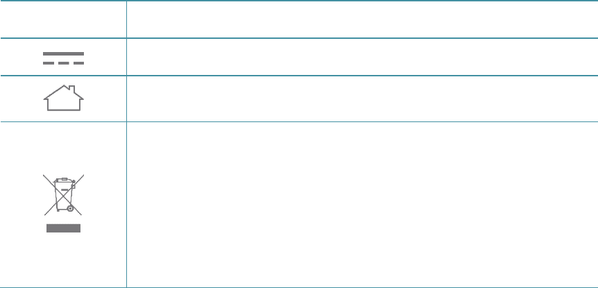
Explanation of the symbols on the product label
Symbol Explanation
DC voltage
Indoor use only
RECYCLING
This product bears the selective sorting symbol for Waste electrical and electronic
equipment (WEEE).
This means that this product must be handled pursuant to
European directive 2012/19/EU in order to be recycled or dismantled to minimize
its impact on the environment.
User has the choice to give his product to a competent recycling organization or to
the retailer when he buys a new electrical or electronic equipment.
CONTENTS
About This Guide ...................................................................................................... 1
Chapter 1. Introduction ............................................................................................ 2
1.1 Product Overview ........................................................................................................... 2
1.2 Product Appearance ..................................................................................................... 2
1.2.1 LEDs .................................................................................................................................... 2
1.2.2 Ports and Buttons................................................................................................................. 3
Chapter 2. Connecting the Modem Router ............................................................. 5
2.1 Positioning the Modem Router ....................................................................................... 5
2.2 Connecting the Modem Router ....................................................................................... 6
Chapter 3. Quick Installation Guide ........................................................................ 8
Chapter 4. Configuring the Modem Router .......................................................... 11
4.1 Login ............................................................................................................................ 11
4.2 Device Info ................................................................................................................... 11
4.3 Advanced Setup ........................................................................................................... 12
4.3.1 Layer2 Interface ................................................................................................................. 13
4.3.2 WAN Service ...................................................................................................................... 16
4.3.3 MAC Clone ......................................................................................................................... 23
4.3.4 LAN .................................................................................................................................... 24
4.3.5 NAT .................................................................................................................................... 27
4.3.6 Security .............................................................................................................................. 32
4.3.7 Parental Control ................................................................................................................. 36
4.3.8 Quality of Service ............................................................................................................... 38
4.3.9 Routing ............................................................................................................................... 40
4.3.10 DNS .................................................................................................................................... 42
4.3.11 DSL .................................................................................................................................... 44
4.3.12 UPnP .................................................................................................................................. 44
4.3.13 Interface Grouping ............................................................................................................. 45
4.3.14 IP Tunnel ............................................................................................................................ 46
4.3.15 Multicast ............................................................................................................................. 48
4.4 IPTV ............................................................................................................................. 49
4.5 Wireless ....................................................................................................................... 49
4.5.1 Basic .................................................................................................................................. 50
4.5.2 Security .............................................................................................................................. 51
4.5.3 Wireless Schedule ............................................................................................................. 62
4.5.4 MAC Filter .......................................................................................................................... 63
4.5.5 Wireless Bridge .................................................................................................................. 64
4.5.6 Advanced ........................................................................................................................... 65
4.5.7 Station info ......................................................................................................................... 66
4.6 Guest Network.............................................................................................................. 66
4.6.1 Basic .................................................................................................................................. 66
4.6.2 Station list ........................................................................................................................... 67
4.7 Diagnostics ................................................................................................................... 68
4.8 Management ................................................................................................................ 68
4.8.1 Settings .............................................................................................................................. 69
4.8.2 System Log ........................................................................................................................ 71
4.8.3 SNMP Agent ...................................................................................................................... 72
4.8.4 TR-069 Client ..................................................................................................................... 73
4.8.5 Internet Time ...................................................................................................................... 74
4.8.6 Access Control ................................................................................................................... 75
4.8.7 Firmware Upgrade ............................................................................................................. 77
4.8.8 Reboot ................................................................................................................................ 77
4.9 Logout .......................................................................................................................... 78
Appendix A: Configuring the PC ........................................................................... 79
Appendix B: Troubleshooting ............................................................................... 84

TD-W8960N User Guide
1
About This Guide
This guide is a complement to Quick Installation Guide. The Quick Installation Guide instructs you
on quick internet setup, and this guide provides details of each function and shows you the way to
configure these functions appropriate to your needs.
When using this guide, please notice that features of the router may vary slightly depending on the
model and software version you have, and on your location, language, and internet service
provider. All screenshots, images, parameters and descriptions documented in this guide are used
for demonstration only.
Conventions
In this guide, the following conventions are used:
Convention Description
Teal Underlined
Hyperlinks are in blue with an underline. You can click to redirect to a
website or a specific section.
Teal
Contents to be emphasized and texts on the web page are in teal,
including the menus, items, buttons, etc.
→
The menu structures to show the path to load the corresponding page. For
example, Network → WAN Settings
means the WAN settings
configuration page is under the Network menu.
Note Ignoring this type of note might result in a malfunction or damage to the
device.
More Info
The latest software, management app and utility can be found at the Download Center page at
http://www.tp-link.com/support.
The Quick Installation Guide can be found where you find this guide or inside the package of the
modem router.
Specifications can be found on the product page at http://www.tp-link.com.
A Technical Support Forum is provided for you to discuss our products at http://forum.tp-link.com.
Our Technical Support contact information can be found at Contact Technical Support page at
http://www.tp-link.com/support.
TD-W8960N User Guide
2
Chapter 1. Introduction
1.1 Product Overview
TP-Link’s Modem router is a combined wired/wireless network connection device with integrated
wireless router and DSL modem, reducing hassle of configuration and saving space.
With DSL and WAN ports, the modem router is compatible with DSL connections and fiber/cable
access.
With Ethernet ports and antennas, the modem router provides wired and wireless access for
multiple computers and mobile devices.
With various features and functions, the modem router is the perfect hub of your home or business
network.
1.2 Product Appearance
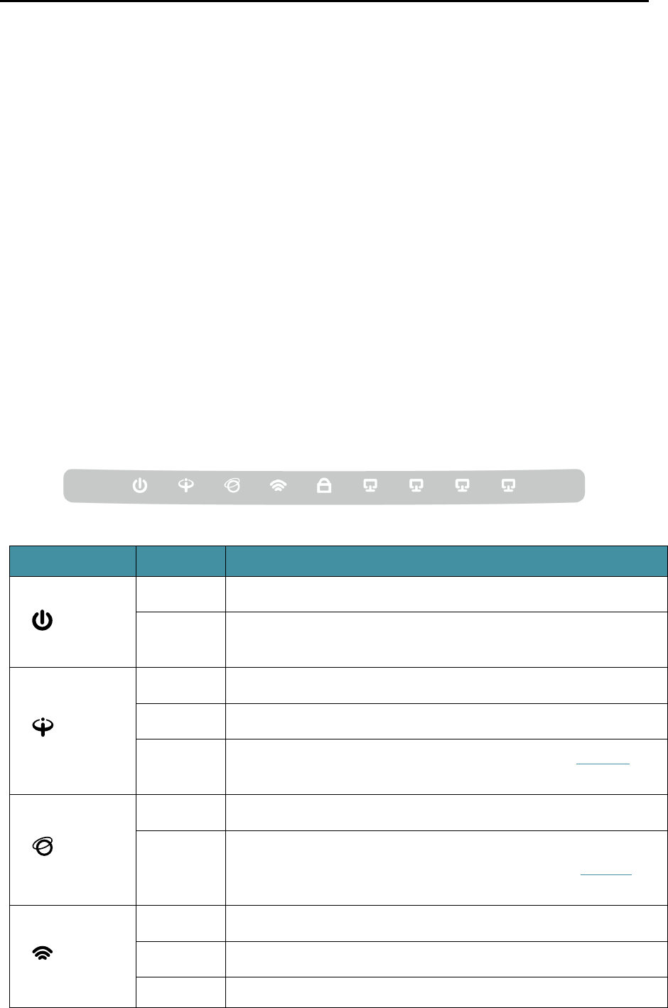
1.2.1 LEDs
The modem router’s LEDs are located on the front panel (View from left to right). They indicate the
device’s working status. For details, please refer to LED Explanation.
LED Explanation:
Name Status Indication
(Power)
On The modem router is powered on.
Off The modem router is off. Please ensure that the power adapter is
connected correctly.
(ADSL)
On ADSL line is synchronized and ready to use.
Flash The ADSL negotiation is in progress.
Off ADSL synchronization fails. Please refer to Note 1 for
troubleshooting.
(Internet)
On The network is available with a successful internet connection.
Off
There is no successful internet connection or the modem router
is operating in Bridge mode. Please refer to Note 2 for
troubleshooting.
(Wi-Fi)
On Wireless is enabled.
Flash The modem router is sending or receiving data over Wi-Fi.
Off Wireless is disabled.
TD-W8960N User Guide
3
(WPS)
On A wireless device has been successfully added to the network by
WPS function.
Flash
WPS handshaking is in process and will continue for about 2
minutes. Please press the WPS button on other wireless devices
that you want to add to the network while the LED is flashing.
Off
The WPS function is disabled or the wireless device fails to be
added to the network in 2 minutes after WPS function is enabled.
For more information, please refer to WPS Setup.
(LAN1-4)
On There is a device connected to this LAN port.
Flash
The modem router is sending or receiving data over this LAN
port.
Off There is no device connected to this LAN port.
Note:
1) If the ADSL LED is off, please check your internet connection first. Refer to 2.3 Connecting the
Modem Router for more information about how to make internet connection correctly. If you have
already made a right connection, please contact your ISP to make sure if your internet service is
available now.
2) If the Internet LED is off, please check your ADSL LED first. If your ADSL LED is also off, please
refer to Note 1. If your ADSL LED is GREEN ON, please check your internet configuration. You
may need to check this part of information with your ISP and make sure everything have been input
correctly. Refer to 4.2 Device Info for more information.
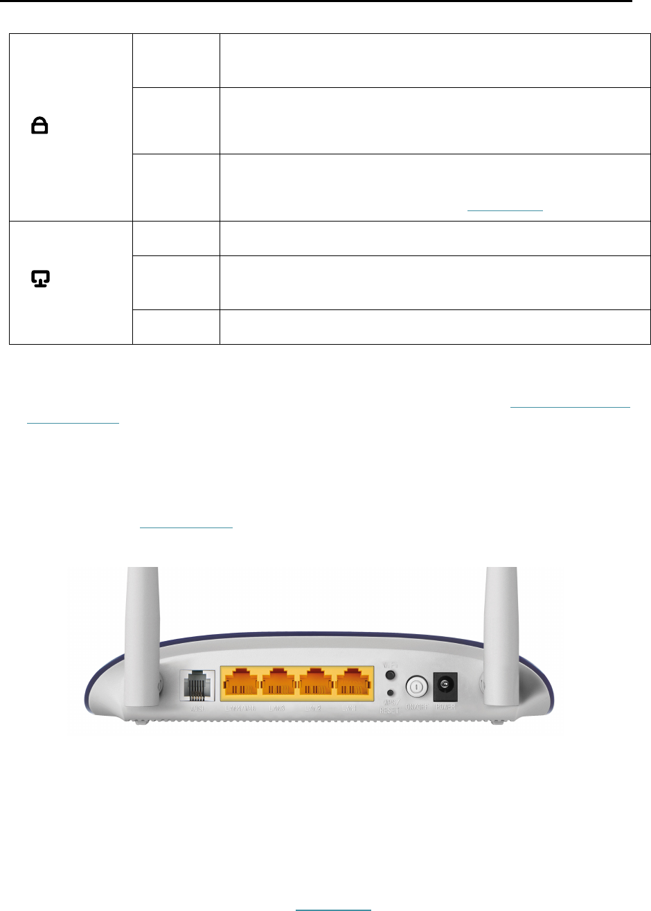
1.2.2 Ports and Buttons
ADSL: Connect to the Modem Port of Splitter or to the telephone line.
LAN4/WAN, LAN3, LAN2, LAN1: Through these ports, you can connect the router to your PC
or the other Ethernet network devices. Enable EWAN function and you will be able to connect
to Cable/FTTH/ADSL device.
WiFi: The switch for the Wi-Fi function.
WPS/RESET:
1) WPS function: For details, please refer to WPS Setup.
2) Reset the modem router: With the modem router powered on, press and hold down the
WPS/RESET button on the rear panel of the modem router for more than 5 seconds and then
release it. If all LEDs turn on momentarily, you restore the modem router successfully.

TD-W8960N User Guide
4
ON/OFF: The switch for the power.
POWER: The Power plug is where you will connect the power adapter.
Wireless Antennas: To receive and transmit the wireless data.
TD-W8960N User Guide
5
Chapter 2. Connecting the Modem Router
2.1 Positioning the Modem Router
With the modem router, you can access your network from anywhere within the wireless network
coverage. However, the wireless signal strength and coverage vary depending on the actual
environment of your modem router. Many obstacles may limit the range of the wireless signal, for
example, concrete structures or thick walls.
For your security and best Wi-Fi performance, please note the following:
Do NOT locate the modem router in a place where it will be exposed to moisture or excessive
heat.
Keep away from the strong electromagnetic radiation and the device of electromagnetic
sensitive.
Place the modem router in a location where it can be connected to the various devices as well
as to a power source.
Make sure the cables and power cord are safely placed out of the way so they do not create a
tripping hazard.
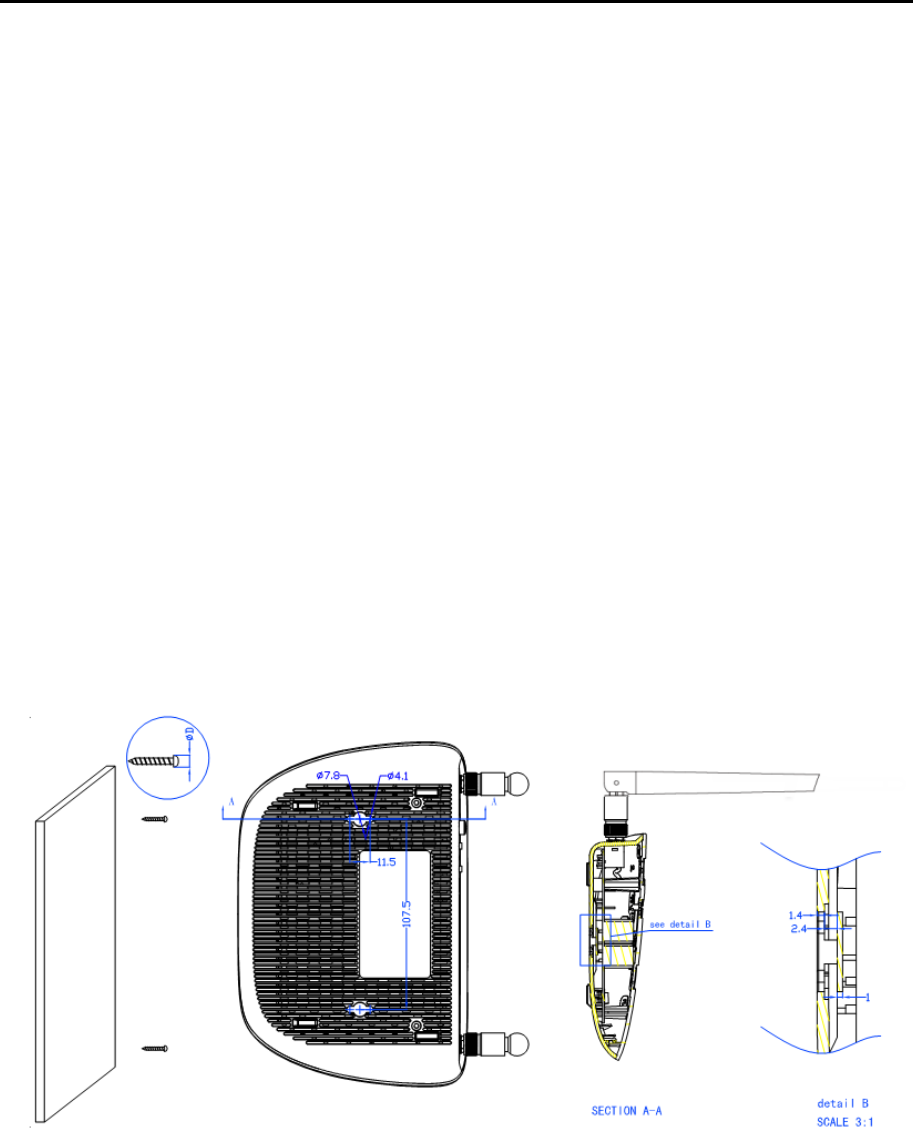
Generally, the modem router is placed on a horizontal surface, such as a shelf or desktop. The device
also can be mounted on the wall as shown below.
Note:
The diameter of the screw, 4.1mm<D<7.8mm, and the distance of two screws is 107.5mm. The screw
that project from the wall need around 4mm based, and the length of the screw need to be at least
20mm to withstand the weight of the product.
TD-W8960N User Guide
6
2.2 Connecting the Modem Router
Before installing the device, please make sure your broadband service provided by your ISP is
available. If there is any problem, please contact your ISP. Before cable connection, cut off the
power supply and keep your hands dry. You can follow the steps below to install it.
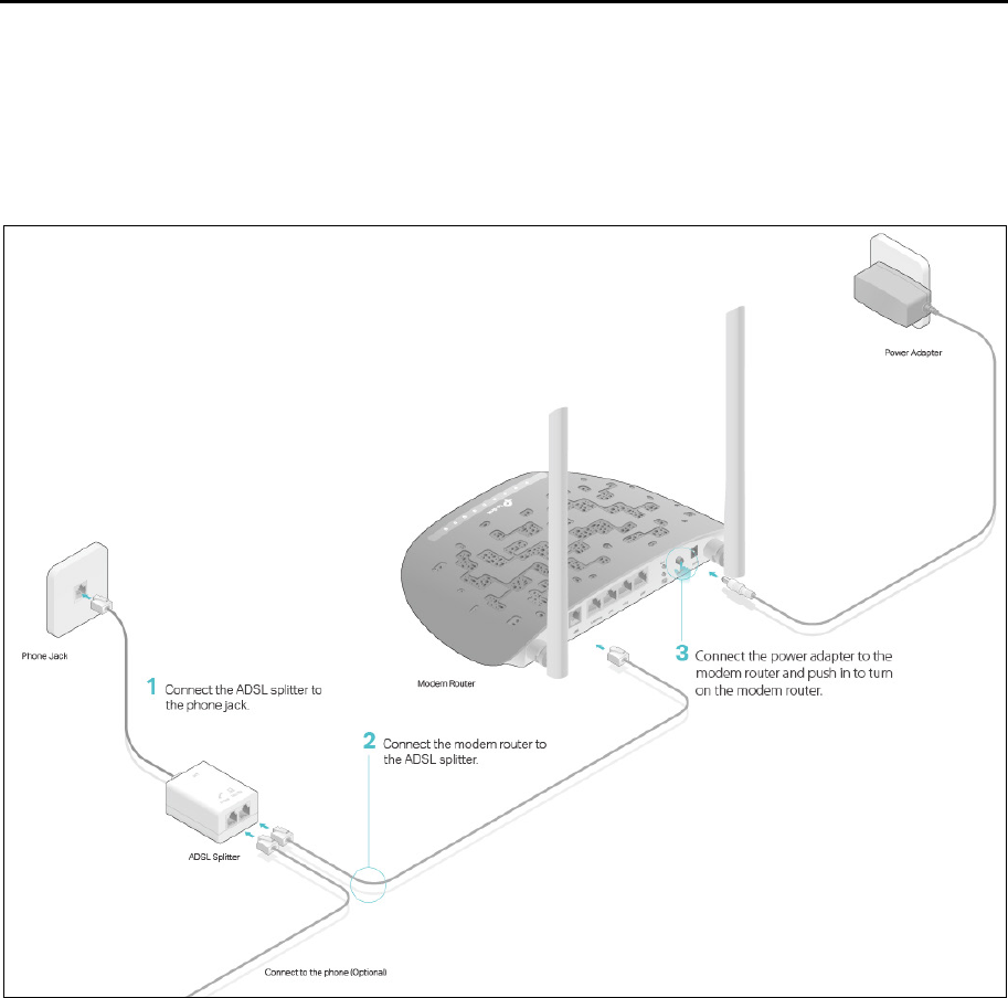
Step 1: Connect the ADSL Line.
Method one: Directly connect the modem router to the phone jack with the ADSL line.
Method two:Connect the modem router to the phone jack via a separate splitter. External
splitter can divide the data and voice, and then you can access the internet and make calls at
the same time. The external splitter has three ports:
• LINE: Connect to the wall jack
• PHONE: Connect to the phone sets
• MODEM: Connect to the DSL port of the modem router
Plug one end of the twisted-pair DSL cable into the VDSL port on the rear panel of the modem
router. Connect the other end to the MODEM port of the external splitter.
Step 2: Connect your computer to the modem router.
Method One: Wired
Connect the computer to a LAN port on your modem router with an Ethernet cable.
Method Two: Wireless

TD-W8960N User Guide
7
Click the network icon of your computer or go to Wi-Fi Setting of your smart device, then use
the default SSID (Wireless Network Name) and Wireless Password printed on the product
label of the modem router to join the network.
Method Three: Via the WPS button
Wireless devices that support WPS, including Android phones, tablets, most USB network
cards, can be connected to your router through this method. (WPS is not supported by iOS
devices.)
Note:
The WPS function cannot be configured if the wireless function of the modem router is disabled. Also,
the WPS function will be disabled if your wireless encryption is WEP. Please make sure the wireless
function is enabled and is configured with the appropriate encryption before configuring the WPS.
1) Tap the WPS icon on the device’s screen.
2) Immediately press the WPS button on your modem router.
3) The WPS LED flashes for about two minutes during the WPS process.
4) When the WPS LED is on, the client device has successfully connected to the modem
router.
Step 3: Attach the power adapter. The electrical outlet shall be installed near the device and shall
be easily accessible.
TD-W8960N User Guide
8
Chapter 3. Quick Installation Guide
This chapter will show you how to configure the basic functions of your modem router using Quick
Setup Wizard within minutes.
1. If the TCP/IP Protocol on your computer is set to a static IP address, you need to change it to
obtain an IP address automatically. Please refer to Appendix A: Configuring the PC for more
detailed instruction.
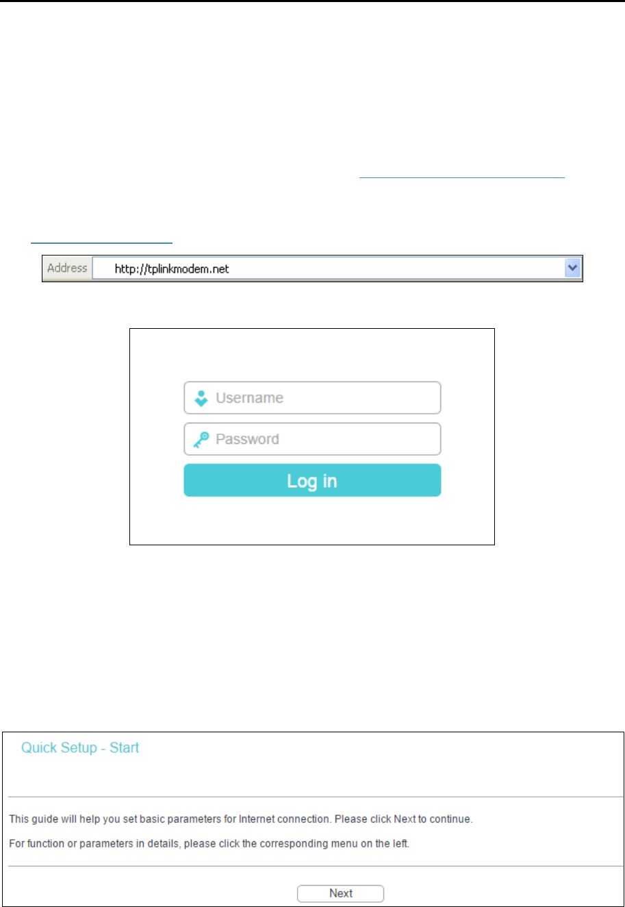
2. To access the configuration utility, open a web-browser and type the default address
http://tplinkmodem.net in the address field of the browser.
After a moment, a login window will appear. Enter admin for the Username and Password,
both in lower case letters. Then click Log in or press the Enter key.
Note:
1) Do not mix up the username and password with your ADSL account username and password
which are needed for PPP connections.
2) If the above screen does not pop up, it means that your web browser has been set to a proxy. Go to
Tools → Internet Options → Connections → LAN Settings, in the screen that appears, cancel
the Using Proxy checkbox, and click OK to finish it.
3. After your successful login, you will see the Quick Setup Wizard. Click Next to continue.
TD-W8960N User Guide
9
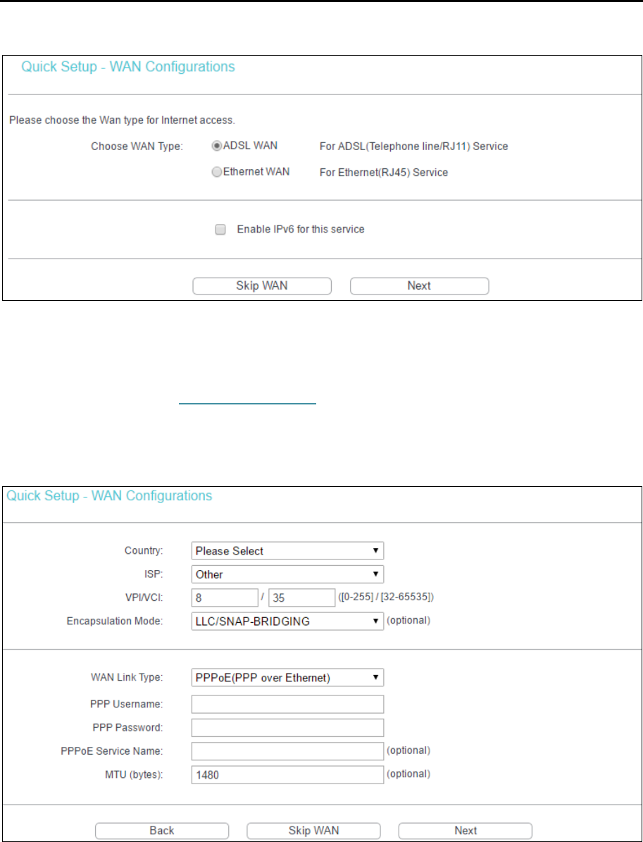
4. Choose the WAN Type for internet access, and then click Next.
Note:
1) The Quick Setup Wizard will guide you to configure the WAN Service over ATM interface.
2) If you are unwilling to configure WAN Service now, you can click Skip WAN. Then you can configure
WAN service referring to 4.3.1 Layer2 Interface.
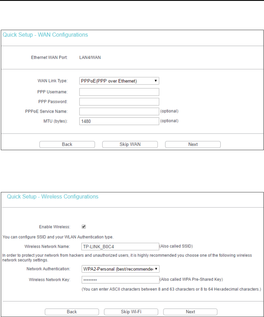
5. If ADSL WAN is chosen, please select your Country and ISP from the drop-down list. Select
WAN Link Type provided by your ISP and enter the related parameters, and then click Next.
Here we use PPPoE as an example.
Note:
If your country or ISP is not listed, please select Other. Then you can manually enter the VPI/VCI
values and select WAN Link Type.
TD-W8960N User Guide
10
If Ethernet WAN is chosen, please select WAN Link Type provided by your ISP and enter the
related parameters, then click Next. Here we use PPPoE as an example.
6. The WLAN function is enabled by default. You can rename your wireless network and create
your own password in this page. The default wireless name is TP-LINK_XXXX, and the
default wireless password which is the same as the PIN code, is printed on the bottom label.
Click Next to continue.
7. You will see the Summary screen, click Confirm to make your configurations take effect.
TD-W8960N User Guide
11
Chapter 4. Configuring the Modem Router
This chapter will show each web management page's key function and the configuration way.
4.1 Login
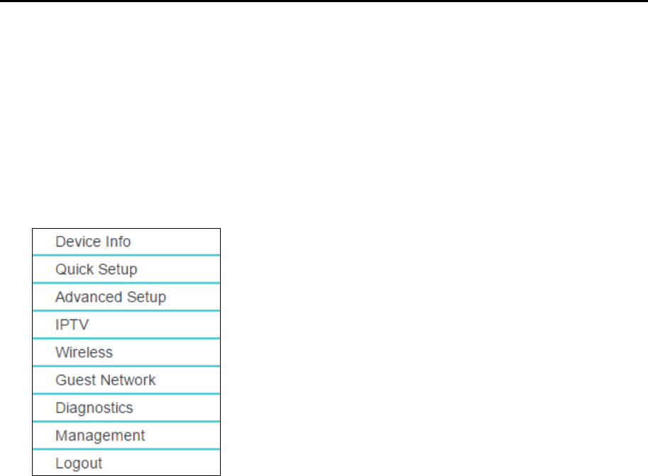
After your successful login, you will see the main menus on the left of the web management page.
On the right, there are the corresponding explanations and instructions.
The detailed explanations for each web management page’s key function are listed below.
4.2 Device Info
Go to Device Info, there are six submenus under the main menu: Summary, WAN, Statistics,
Route, ARP and DHCP. This Device Info section mainly introduces the elementary information
about the modem router and its current settings in use. Click any of them, and you can view the
corresponding information.
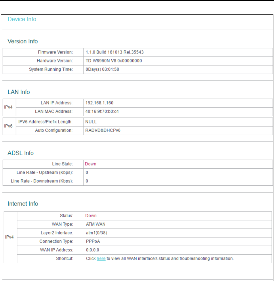
Go to Device Info → Summary, you will see the Summary screen. The first table indicates the
information about the version including Software and Hardware. The second table displays the
current status of the modem router connection. This information varies depending on the settings
of the router configured on the Advanced Setup screen.
TD-W8960N User Guide
12
Note:
Click the other submenus under the main menu Device Info, and you will be able to view the
corresponding information about WAN, Statistics, Route, ARP and DHCP.
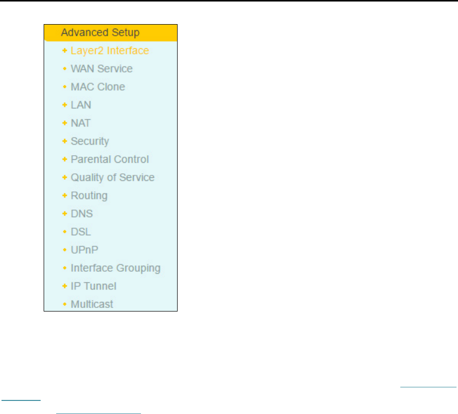
4.3 Advanced Setup
Go to Advanced Setup, there are many submenus under the main menu. Among the submenus,
Layer2 Interface, WAN Service, LAN etc. are default menus, while NAT will appear only when you
select some corresponding functions. Click any one of them, and you will be able to configure the
corresponding function.
TD-W8960N User Guide
13
This Advanced Setup section mainly introduces how to configure the router for adequate use. The
detailed explanations for each subsection are provided below.
Note:
To completely configure the WAN Interface, you need to first select the Layer2 Interface (4.3.1 Layer2
Interface) according to the connection ISP provides for you, and then to select the type of the
connection (4.3.2 WAN Service) for the further configuration.
4.3.1 Layer2 Interface
Go to Advanced Setup → Layer2 Interface, and you can select WAN Service Interface (layer2
interface) over ATM Interface or ETH Interface.
ATM Interface: Configure the router to access internet as an ADSL user. ISP provides you
VPI (Virtual Path Identifier), VCI (Virtual Channel Identifier) settings and the DSL Interface
with RJ11 connector.
ETH Interface: Configure the router to access internet as an Ethernet user. ISP provides you
Broadband Internet Service and the Ethernet Interface with RJ45 connector.
4.3.1.1 ATM Interface
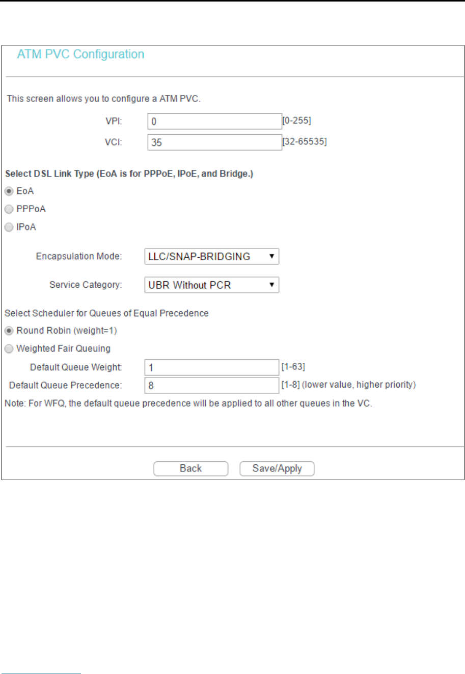
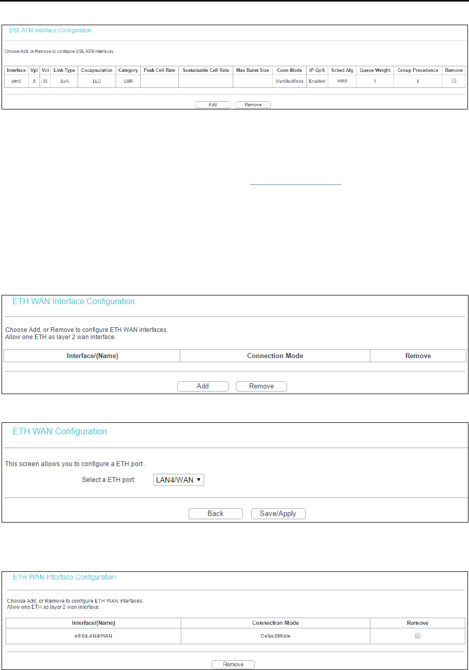
Go to Advanced Setup → Layer2 Interface → ATM Interface, you can Configure ATM interfaces
on the screen below.
TD-W8960N User Guide
14
Add: Click to add a new interface in the next screen.
VPI/VCI: the VPI and VCI values provided by your ISP. Do not change them unless it was
required by your ISP.
DSL Link Type: Select the DSL Link Type provided by your ISP. The options include EoA (it
is for PPPoE, IPoE, and Bridge), PPPoA (PPP over ATM) and IPoA (IP over ATM).
Encapsulation Mode: The mode of data processing over the Link Type you have selected.
Use the default settings, if you are not sure.
Service Category: Select the type of the service assigned by your ISP in the drop-down list.
The default type is UBR Without PCR.
Note:
The detailed configuration about Scheduler for Queues of Equal Precedence will be described in
Quality of Service.
TD-W8960N User Guide
15
Remove: Select the checkbox in the table and then click Remove, then the corresponding
interface will be deleted from the table.
Note:
If the interface is used by the configuration of the 4.3.2 WAN Service, you need to remove the
corresponding WAN Service entry before removing it here.
4.3.1.2 ETH Interface
Go to Advanced Setup → Layer2 Interface → ETH Interface, you can configure ETH WAN
interfaces on the screen below.
Add: Click to add a new interface in the next screen.
ETH port: Select an ETH port to configure as the WAN port.
Click Save/Apply to make settings effective.
Remove: Select the checkbox in the table and then click Remove, then the corresponding
interface will be deleted from the table.

TD-W8960N User Guide
16
Note:
Only one ETH is allowed to configure as the layer 2 WAN Interface.
4.3.2 WAN Service
Go to Advanced Setup → WAN Service, and you will see the WAN Port Information Table, which
describes the WAN port settings and the relevant manipulation to each interface. After you add a
new Layer2 Interface, please follow the instructions below to complete the further configuration of
WAN Interface. There are five different configurations for the connection types, which are PPPoE,
IPoE, Bridge, PPPoA, and IPoA. You can select the corresponding types according to your needs.
Note:
Bridge mode is not available under Wireless Router Mode.
Note:
The following section adopts different VPI, VCI to introduce further configuration for the different
connection types, if you need to change the configuration of ATM PVC (VPI/VCI), go to the previous
section (4.3.1 Layer2 Interface) to configure them again.
4.3.2.1 ATM-EoA-PPPoE
If your ISP provides a PPPoE connection and you need to use an ATM Interface, follow the steps
below to add a WAN service over a selected ATM interface:
1. Add a new ATM interface (4.3.1.1 ATM Interface).
2. Click Add and you will enter the next screen as shown below. Click Next.
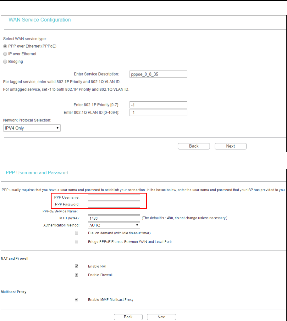
3. Select the WAN service type. If your ISP provides a PPPoE connection, select PPPoE. You
can create a service name for the Service Description or leave it as default. Then click Next.
TD-W8960N User Guide
17
4. Enter the following parameters and then click Next.
PPP Username/Password: Enter the Username and Password provided by your ISP. These
fields are case-sensitive.
PPPoE Service Name: Enter the Service Name if it was provided by your ISP. You can leave
it blank if the ISP doesn’t provide it.
MTU (bytes): Maximum Transmission Unit Size. The default MTU value is 1480 Bytes. It is
not recommended that you change the default value unless required by your ISP.
Authentication Method: Select the Authentication Method from the drop-down list, the
default method is AUTO, and you can leave it as a default setting.
Dial on demand (with idle timeout timer): The router will cut off the internet connection after
it has been inactive for a specific period of time (idle timeout), and it will automatically
re-establish the connection as soon as you attempt to access the internet again. If your
internet is charged by time you may want to select this option in order to save money.
TD-W8960N User Guide
18
Bridge PPPoE Frames Between WAN and Local Ports: Select this option to enable PPP
connection in your local PC.
Enable NAT: This technology translates the IP addresses of a local area network to the WAN
IP address for the internet. If this router is hosting your network’s connection to the internet,
please select the checkbox. If another router exists in your network, you don’t need to select
the option.
Enable Firewall: A SPI firewall enhances network’s security. Select the option to use a
firewall, or else without a firewall.
Enable IGMP Multicast Proxy: IGMP (Internet Group Management Protocol) is used to
manage multicasting on TCP/IP networks. Some ISPs use IGMP to perform remote
configuration for client devices, such as the router. The default value is enabled, and if you
are not sure, please contact your ISP or just leave it.
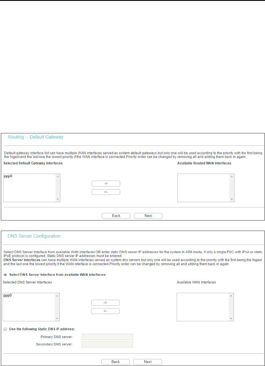
5. Select a preferred wan interface as the system default gateway and click Next.
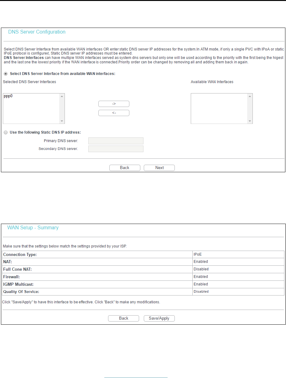
6. Configure the DNS Server Addresses and click Next.
Select DNS Server Interface from available WAN Interfaces: You can select this option to
automatically get DNS server information from the selected WAN interface.
Use the following Static DNS IP Address: You can select this option to manually enter the
primary and /or optional secondary DNS server IP addresses provided by your ISP.
Note:
If only single PVC with IPoA is configured, you must enter static DNS server IP addresses.
TD-W8960N User Guide
19
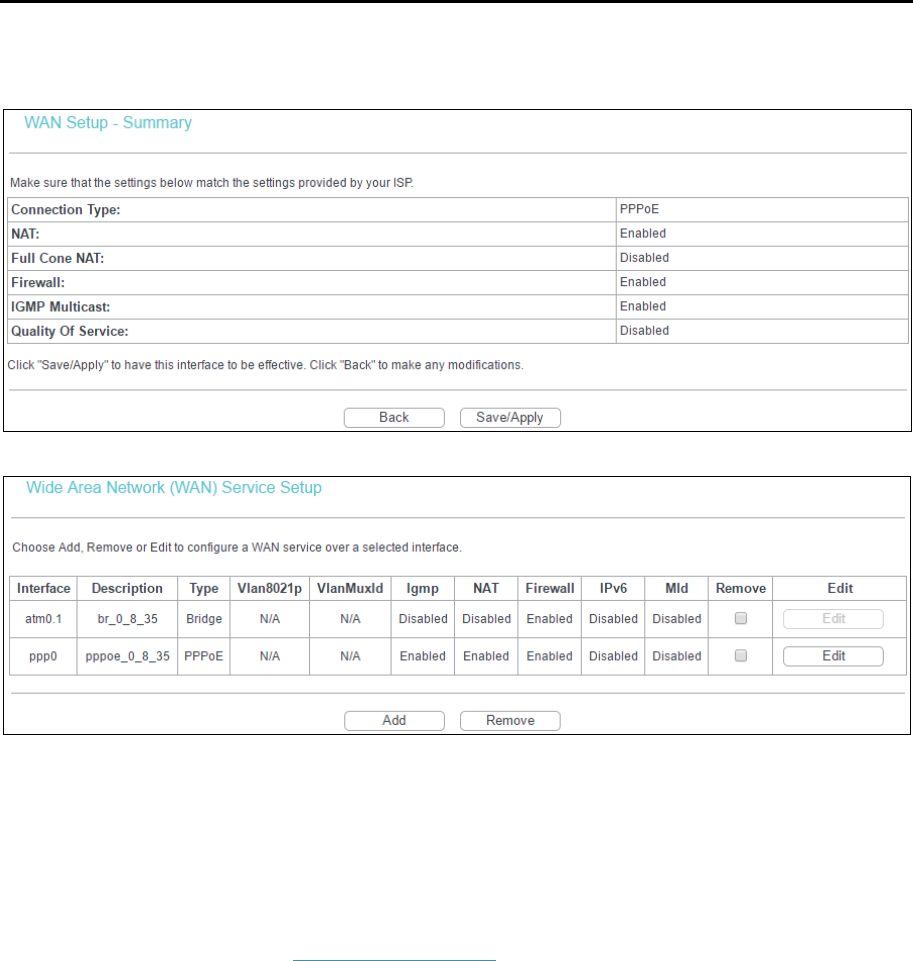
7. On the next screen you will see the detailed settings you’ve made.Click Save/Apply to save
these settings.
8. On the next screen you will see the WAN Port Information Table with the new configuration.
Remove: Select the checkbox in the table and then click Remove, the corresponding
interface will be deleted.
4.3.2.2 ATM-EoA-IPoE
If your ISP provides an IPoE connection and you need to use an ATM Interface, follow the steps
below to add a WAN service over a selected ATM interface:
1. Add a new ATM interface (4.3.1.1 ATM Interface).
2. Click the Add on the screen. Select WAN Service Interface over ATM PVC on the next
screen.
3. If your ISP provides an IPoE connection, select IP over Ethernet option for the WAN service
type on the screen, and click Next to continue.
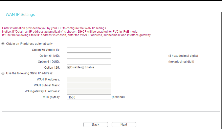
4. Enter parameters in the following blanks to configure the WAN IP Address and click Next.
TD-W8960N User Guide
20
Obtain an IP address automatically: Select this option, the router will be able to obtain IP
network information dynamically from a DHCP server provided by your ISP.
Note:
1) The response message from a DHCP server typically contains a number of configuration
parameters (DHCP options) for the router. The DHCP options include IP network information, and
also the vendor-specific options. In some cases, the router is implemented to perform user-defined
operations (as shown below). You can implement your own treatment of all such options.
2) If the router is functioning as a DHCP client, it must identify itself in option 61 (client-identifier) in
every DHCP message. DUID/IAID is portion of option 61.
• Option 60 Vendor ID: The option code 60 used to identify Vendor class.
• Option 61 IAID: IAID (Identity Association ID) assigns an Identity Association ID to
individual interfaces. In cases where the device is functioning with a single DHCP client
identity, it must use value 1 for IAID for all DHCP interactions. In cases where the device
is functioning with multiple DHCP client identities, the values of IAID have to start at 1 for
the first identity and be incremented for each subsequent identity. For example, the
device may use IAID value 1 for the first physical interface and value 2 for the second.
Alternatively, the device may use IAID value 1 for the virtual circuit corresponding to the
first connection object in the data model and value 2 for the second connection object in
the data model.
• Option 61 DUID: Specifies the name of the interface whose link-layer address the server
is to use as its DUID (DHCP Unique Identifier). You must enter a value for this parameter
or the server will not start. When the server starts, the DUID is written to the system log.
• Option 125: The option 125 allows DHCP server to be pre-configured with policy for
handling classes of devices in a certain way without requiring DHCP server to be able to
parse the unique format used in client-identifier option.
Use the following IP Address: If you are provided with a static IP/gateway Address, please
select this option, and then enter the WAN IP Address, WAN Subnet Mask and WAN gateway
IP Address manually.
TD-W8960N User Guide
21
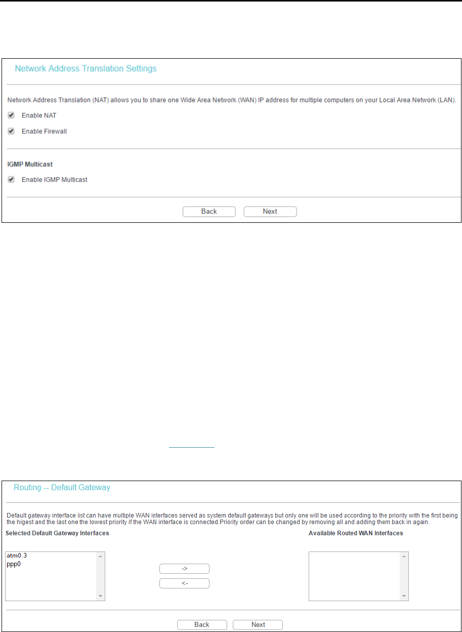
5. You will see the next screen as below. You can enable the NAT, SPI Firewall, and IGMP
Multicast. If you are not sure about the settings, just leave the default settings. Click Next.
Enable NAT: This technology translates the IP addresses of a local area network to the WAN
IP address for the internet. If this router is hosting your network’s connection to the internet,
please select the checkbox. If another router exists in your network, you don’t need to select
the option.
Enable Firewall: A SPI firewall enhances network’s security. Select the option to use a
firewall, or else without a firewall.
Enable IGMP Multicast: This is enabled by default. This setting will not allow IGMP (Internet
Group Management Protocol) packets to be forwarded to the LAN. IGMP is used to manage
multicasting on TCP/IP networks. Most users will not need to enable this. Some ISPs use
IGMP to perform remote configuration for client devices, such as the router. If you are unsure,
check with your ISP.
Note:
If you select the Enable NAT checkbox, the NAT menu will be added to the Web-based Utility. We will
describe the detailed configuration in 4.3.5 NAT.
6. Select a preferred WAN interface as the system default gateway and click Next.
TD-W8960N User Guide
22
7. Configure the DNS Server Addresses on the screen as follows.
Note:
If only single PVC with IPoA is configured, you must enter static DNS server IP addresses.
8. On the next screen you will see the detailed settings you’ve made. Please click Save/Apply to
save these settings.
4.3.2.3 ATM-EoA-Bridging
If you want to adopt the Bridge service and you need to use an ATM Interface, follow the steps
below to add a WAN service over a selected ATM interface:
1. Add a new ATM interface (see 4.3.1.1 ATM Interface).
2. Click Add and select WAN Service Interface over ATM PVC on the next screen.
3. Select Bridging option for the WAN service type on the screen, and click Next to continue.
4. On the screen you will see the detailed settings you’ve made. Please click Save/Apply to save
these settings.

TD-W8960N User Guide
23
4.3.2.4 ATM-PPPoA
If your ISP provides a PPPoA connection and you need to use an ATM Interface, follow the steps
below to add a WAN service over a selected ATM interface:
1. Add a new ATM interface and select PPPoA option for DSL Link Type (see 4.3.1.1 ATM
Interface).
2. Click Add and the next configuration is similar to PPPoE, (see section 4.3.2.1
ATM-EoA-PPPoE). The difference is that you don’t need to set the PPPoE Service Name and
Bridge PPPoE Frames Between WAN and Local Ports.
4.3.2.5 ATM-IPoA
If your ISP provides an IPoA connection and you need to use an ATM Interface, follow the steps
below to add a WAN service over a selected ATM interface.
1. Add a new ATM interface and select IPoA option for DSL Link Type (see 4.3.1.1 ATM
Interface).
2. Click Add and the next configuration is similar to IPoE (see section 4.3.2.2 ATM-EoA-IPoE).
The difference is that you have to manually set the Static IP Address, and the Static IP
Address for DNS Server.
4.3.2.6 ETH-PPPoE
If your ISP provides a PPPoE connection and you need to use an ETH Interface, follow the steps
below to add a WAN service over a selected ETH interface:
1. Add a new ETH interface on the screen of 4.3.1.2 ETH Interface.
2. Click Add and the next configuration is similar to PPPoE over ATM interface (see section
4.3.2.1 ATM-EoA-PPPoE).
4.3.2.7 ETH-IPoE
If your ISP provides an IPoE connection and you want to use an ETH Interface, follow the steps
below to add a WAN service over a selected ETH interface:
1. Add a new ETH interface on the screen of 4.3.1.2 ETH Interface.
2. Click Add and the next configuration is similar to IPoE over ATM interface (see section 4.3.2.2
ATM-EoA-IPoE).
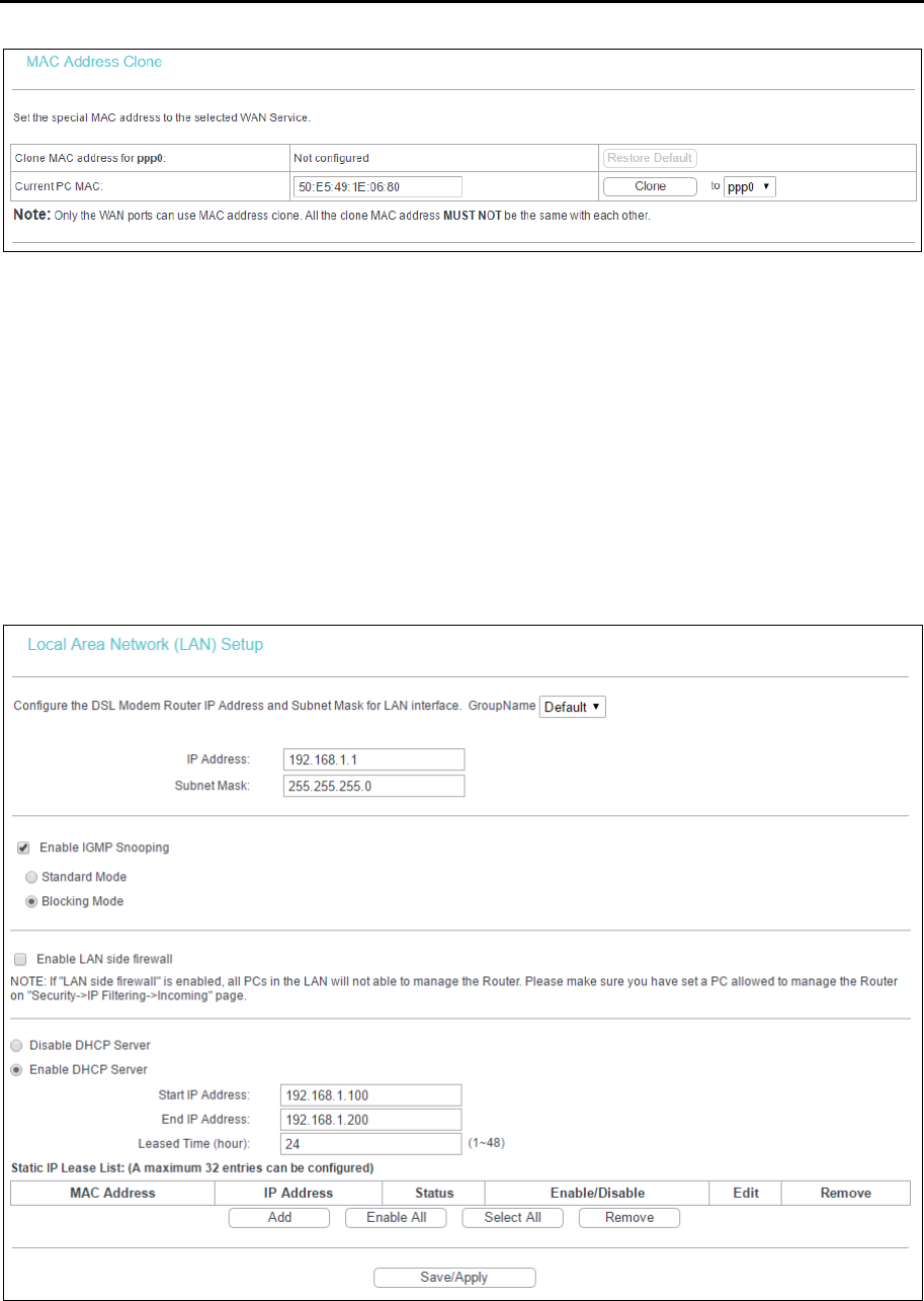
4.3.3 MAC Clone
Go to Advanced Setup → MAC Clone, you can configure the MAC address of the WAN Interface
as shown below.
The WAN Interface List displays the Lay2 Interfaces you have configured on the section 4.3.1
Layer2 Interface and its default MAC Address. If you have not configured corresponding WAN
Service for the interface on the section 4.3.2 WAN Service, the blank for MAC Address will display
Need a corresponding WAN Service.
The last one of WAN Interface List displays your PC’s current address.
TD-W8960N User Guide
24
Type the new value for the WAN Interface whose MAC Address you want to change.
You can select corresponding WAN Interface from the drop-down list and click Clone to clone your
current PC MAC.
Click Restore Default to restore the WAN Interface’s default MAC Address.
Note:
Only the WAN Ports can use MAC Address Clone function. All the clone MAC addresses must not be
the same with each other.
4.3.4 LAN
Go to Advanced Setup → LAN, and you will see the LAN screen which allows you to configure the
router’s LAN ports settings.
IP Address: Enter the router’s local IP Address, then you can access to the web
management page via the IP Address, the default value is 192.168.1.1.
Subnet Mask: Enter the router’s Subnet Mask, the default value is 255.255.255.0.
TD-W8960N User Guide
25
Enable IGMP Snooping: If you select the option, please choose the IGMP Mode: Standard
Mode or Blocking Mode.
Enable LAN side firewall: You can click the checkbox to enable LAN side firewall.
DHCP Server: These settings allow you to configure the router‘s Dynamic Host Configuration
Protocol (DHCP) server function. The DHCP server is enabled by default for the router’s
Ethernet LAN interface. DHCP service will supply IP settings to computers which are
configured to automatically obtain IP settings that are connected to the router though the
Ethernet port. If you enable the DHCP server, the router becomes the default gateway for
DHCP client connected to it. Keep in mind that if you change the IP address of the router, you
must change the range of IP addresses in the pool used for DHCP on the LAN.
• Start IP Address: Enter a value for the DHCP server to start with when issuing IP
addresses. Because the default IP address for the router is 192.168.1.1, the default Start
IP Address is 192.168.1.100, and the Start IP Address must be 192.168.1.2 or greater, but
smaller than 192.168.1.254.
• End IP Address: Enter a value for the DHCP server to end with when issuing IP
addresses. The End IP Address must be smaller than 192.168.1.254. The default End IP
Address is 192.168.1.200.
• Leased Time (hour): The Leased Time is the amount of time in which a network user will
be allowed to connect to the router with their current dynamic IP address. Enter the
amount of time, in hours, then the user will be “leased” this dynamic IP address. The
default is 24 hours.
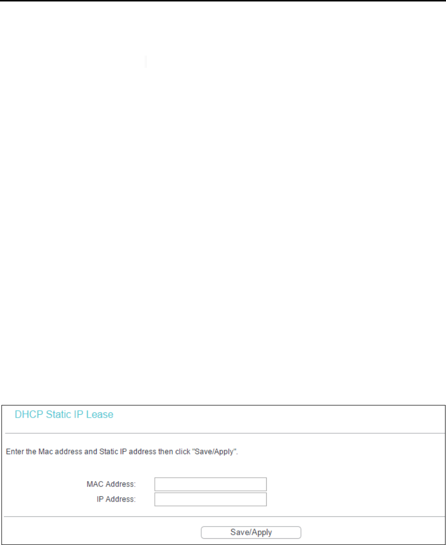
Static IP Lease List: The function allows you to specify a reserved IP address for a PC on the
LAN, that PC will always obtain the assigned IP address each time when it accesses the
DHCP server. Reserved IP addresses should be assigned to servers that require permanent
IP settings. Click Add, and then you will set the rule in the screen as below.
• MAC Address: The MAC address of the computer on the LAN which you want to reserve
an IP.
• IP Address: The IP address you want to reserve for the computer.
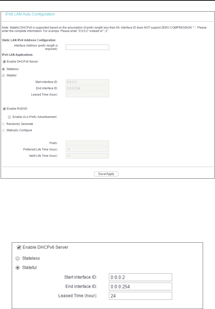
4.3.4.1 IPv6 LAN Config
Go to Advanced Setup → LAN → IPv6 LAN Config, and you will see the LAN screen, here you can
configure LAN IPv6 interface for your modem router.
TD-W8960N User Guide
26
Interface Address (prefix length is required): Here enter your interface address with its
prefix length.
IPv6 LAN Applications: Select a type to assign IPv6 addresses to the computers in your
LAN. DHCPv6 Server and RADVD are provided.
For DHCPv6 Server:
1) If Stateless is selected, it doesn’t need to be configured.
2) If Stateful is selected, please complete the following parameters.
• Start interface ID: Enter a value for the DHCPv6 server to start with when issuing IPv6
addresses.
• End interface ID: Enter a value for the DHCPv6 server to end with when issuing IPv6
addresses.
TD-W8960N User Guide
27
• Leased Time (hour): The Leased Time is the amount of time in which a network user will
be allowed to connect to the modem router with their current dynamic IPv6 address.
Enter the amount of time, in hours, then the user will be “leased” this dynamic IPv6
address. After the dynamic IPv6 address has expired, the user will be automatically
assigned a new dynamic IPv6 address. The default is 24 hours.
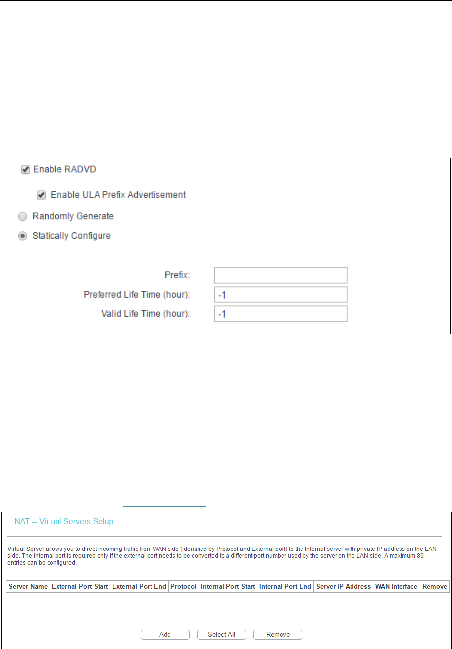
For RADVD:
1) If Randomly Generate is selected, it doesn’t need to be configured.
2) If Statically Configure is selected, please complete the following parameters.
• Prefix: Enter a value for the site prefix.
Click Save/Apply to make the configuration effective.
4.3.5 NAT
NAT (Network Address Translation) allows you to share one WAN (Wide Area Network) IP
address for multiple computers on your LAN (Local Area Network).
Note:
When you select PPPoA or PPPoE for the WAN Setup, or when you select Enable NAT for the type of
IPoA and IPoE connection (4.3.2 WAN Service), you will see the NAT menu in the Web-based Utility.
TD-W8960N User Guide
28
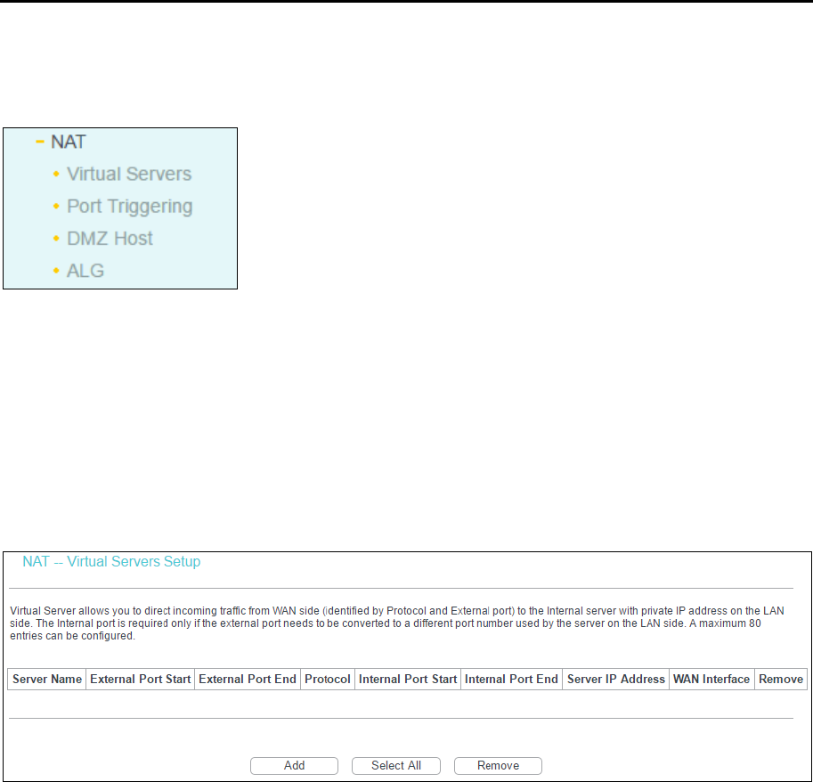
Go to Advanced Setup → NAT, there are 4 submenus under the main menu: Virtual Servers, Port
Triggering, DMZ Host and ALG. Click any of them, and you will be able to configure the
corresponding function.
4.3.5.1 Virtual Servers
Go to Advanced Setup → NAT → Virtual Servers, you can set up virtual servers on the screen
below.
Virtual servers can be used for setting up public services on your LAN, such as DNS, Email and
FTP. A virtual server is defined as a service port, and all requests from the internet to this service
port will be redirected to the computer specified by the server IP. Any PC that was used for a
virtual server must have a static or reserved IP Address because its IP Address may change when
using the DHCP function.
Virtual Server Table: The table indicates the information about the Virtual Server entries.
• Server Name: This is the name of the Virtual Server. It is exclusive and must be filled in.
• External Port Start: The base number of External Ports. You can type a service port or
leave it blank.
• External Port End: The end number of External Ports. You can type a service port or
leave it blank.
• Protocol: The protocol used for this application, TCP, UDP, or TCP/UDP.
• Internal Port Start: The base number of Internal Ports. You can type a service port or
leave it blank.
• Internal Port End: The end number of Internal Ports. You can type a service port or leave
it blank.
• Server IP Address: The IP Address of the PC providing the service application.
• WAN Interface: The WAN Service Interface providing the service application.
Add: Click to add a new entry.
TD-W8960N User Guide
29
Remove: Select the checkbox in the table and then click Remove, then the corresponding
entry will be deleted in the table.
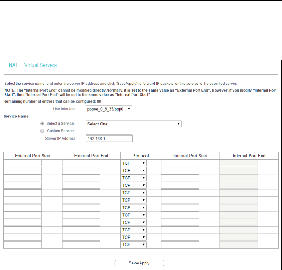
To add a virtual server entry:
1. Click Add and then you will see the new Virtual Server in the next screen.
2. Select the Interface which you want to use from the drop-down list.
3. Select the service which you want to use from the drop-down list. If the list does not have the
service you need, type the name of the custom service in the text box.
4. Type the IP Address of the computer in the Server IP Address text box.
5. Enter the External Port Start, External Port End, Internal Port Start and Internal Port End in
the table, and then select the protocol used for this Virtual Server, TCP, UDP or All.
6. Click Save/Apply to enable virtual server and then you will see your setting.
Note:
If you select the service from the drop-down list, the External Port Start, External Port End, Internal
Port Start, Internal Port End and the Protocol will be added in the table automatically. You only need to
enter the Server IP Address for the Virtual Server.
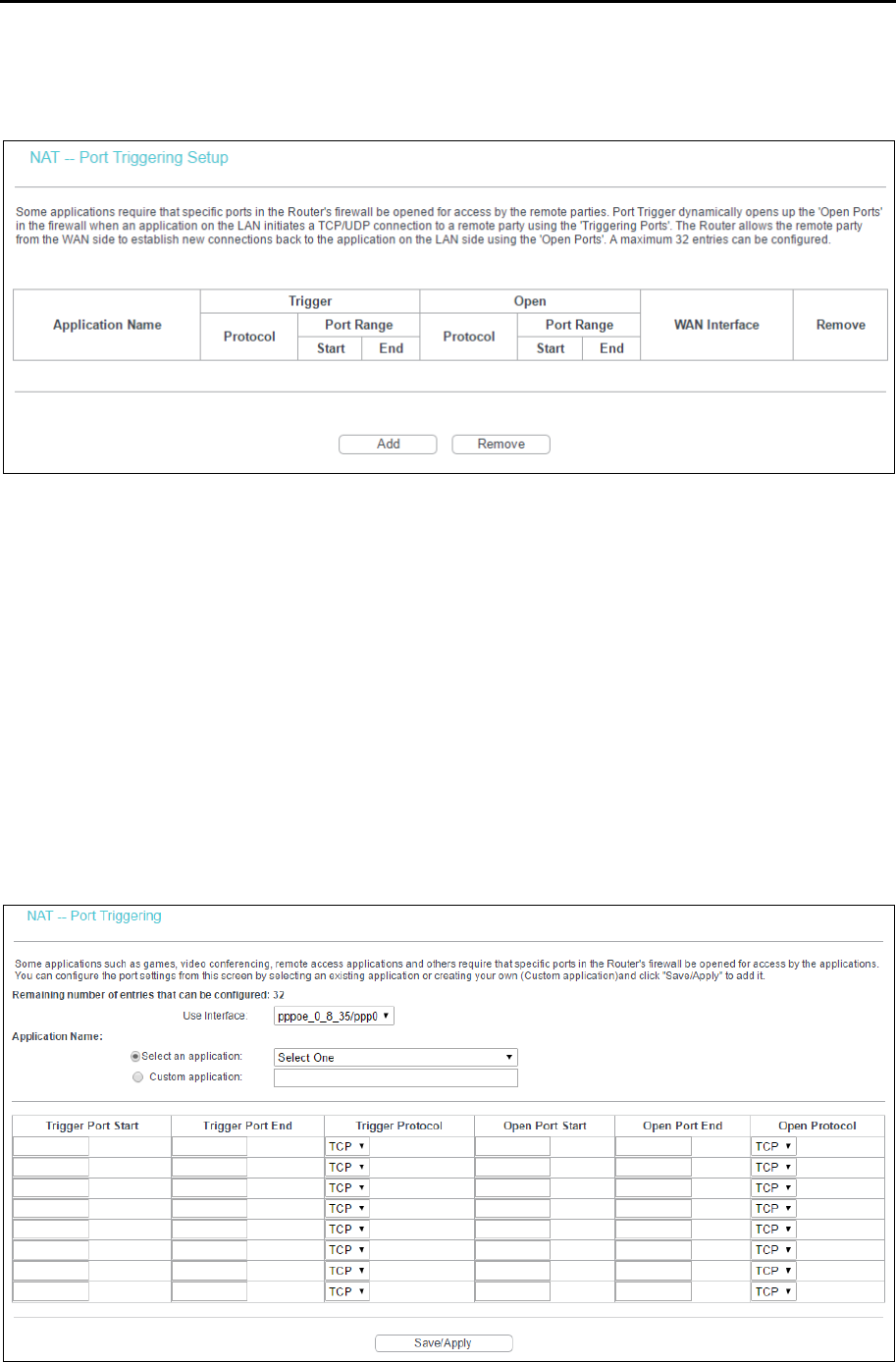
4.3.5.2 Port Triggering
Go to Advanced Setup → NAT → Port Triggering, you can set Port Triggering on the screen.
Some applications require that specific ports in the router's firewall should be opened for access
by remote devices. Port Trigger dynamically opens up the 'Open Ports' in the firewall when an
TD-W8960N User Guide
30
application on the LAN initiates a TCP/UDP connection to a remote device using the triggering
ports. The router allows the remote party from the WAN side to establish new connections back to
the application on the LAN side using the open ports. A maximum 32 entries can be configured.
Port Triggering Table: The table indicates the information about the Port Triggering entries.
• Application (Name): This is the name of the Port Triggering. It is exclusive and must be
filled.
• Trigger: It includes the Protocol and the Start and End value of the Trigger Ports.
• Open: It includes the Protocol and the Start and End value of the Open Ports.
• WAN Interface: The WAN Service Interface setting the Port Triggering.
Add: Click to add a new entry.
Remove: Select the checkbox in the table and then click Remove, then the corresponding
entry will be deleted in the table.
To add a new Port Triggering:
1. Click Add, and then you will see the new Port Triggering in the next screen.
TD-W8960N User Guide
31
2. Select the application from the drop-down list. If the list does not have the application that
you want, select Custom application, and type the name of the custom application in the text
box.
3. Enter the Trigger Port Start, Trigger Port End, Open Port Start and Open Port End in the table,
and then select the Trigger protocol and Open protocol, TCP, UDP or All.
4. Click Save/Apply to make the settings effective.
Note:
If you select the application from the drop-down list, the External Port Start, External Port End, Internal
Port Start, Internal Port End and the Protocol will be added in the table automatically.
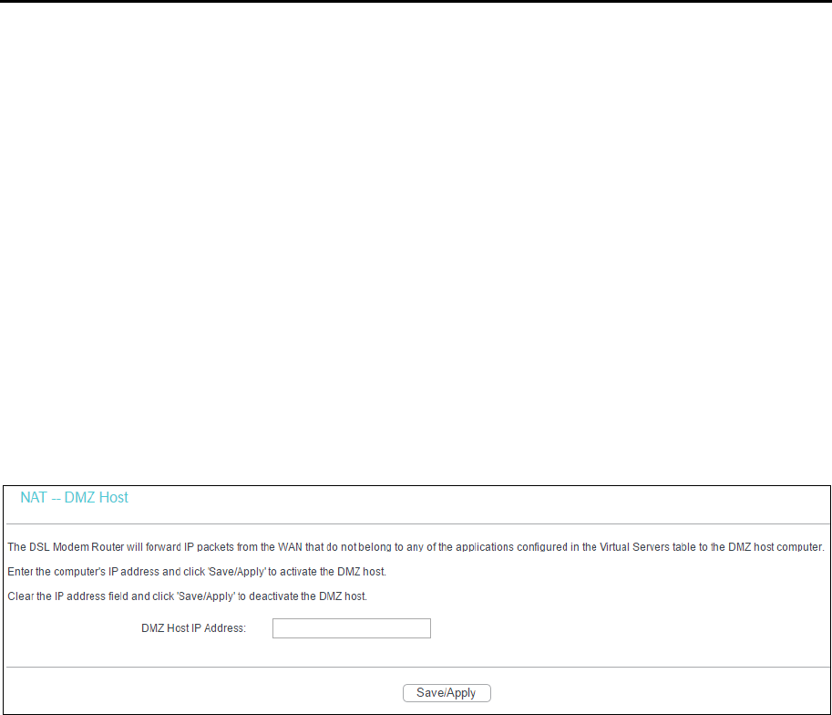
4.3.5.3 DMZ Host
Go to Advanced Setup → NAT → DMZ Host, you can set up DMZ Host on the screen.
The DMZ host feature can make a local host exposed to the internet for a special-purpose service,
such as online gaming or video conferencing.
To add a new DMZ Host:
You can enter the computer's IP address and then click Save/Apply to activate the DMZ host you
set on this page.
Note:
DMZ host forwards all the ports at the same time. Any PC whose port is being forwarded must have its
DHCP client function disabled and should have a new static IP Address assigned to it because its IP
Address may change while using the DHCP function.
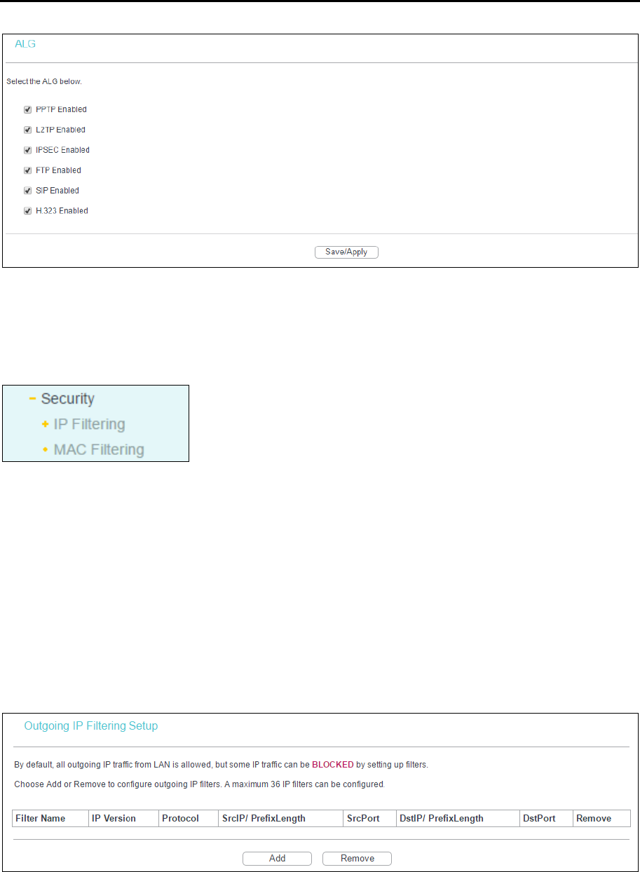
4.3.5.4 ALG
Go to Advanced Setup → NAT → ALG, and then you can configure the basic security in the
screen.
TD-W8960N User Guide
32
Click Save/Apply to make the settings effective.
4.3.6 Security
Go to Advanced Setup → Security, and you will see the security screen including IP Filtering and
MAC Filtering (only effective in Bridge mode) submenus.
4.3.6.1 IP Filtering
The IP address filtering feature makes it possible for administrators to control user's access to the
internet, which is based on user's IP. You can configure Outgoing Filtering or Incoming Filtering
rules according to your needs.
Set up an Outgoing IP Filtering rule:
The Outgoing IP Filtering feature allows you to control some IP traffic from LAN to access to some
specifically addresses. By default, all outgoing IP traffic from LAN is allowed, but some IP traffic
can be BLOCKED by setting up filters.
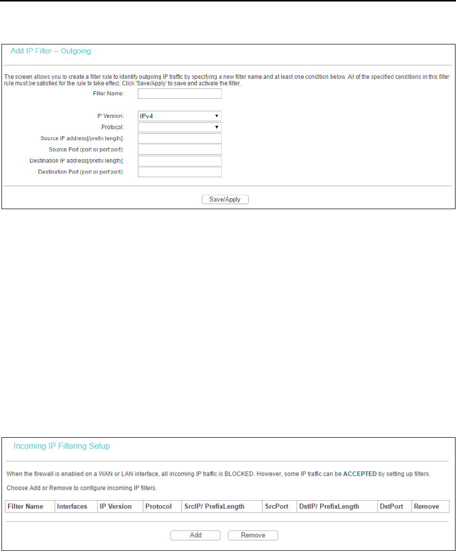
1. Click Add.
TD-W8960N User Guide
33
2. Then you will see the next screen.
3. Enter the Filter name for the rule, it is exclusive and must be filled.
4. Select the protocol in the drop-down list for the connection between the Source IP address
and Destination IP address.
5. Enter a Source IP Address in dotted-decimal notation format and then type Source Port (port
or port: port) in the text boxes separately.
6. Enter a Destination IP Address in dotted-decimal notation format and then type Destination
Port (port or port: port) in the text boxes separately.
7. Click Save/Apply to save this entry.
Set up an Incoming IP Filtering rule:
When the firewall is enabled on a WAN or LAN interface, all incoming IP traffic is BLOCKED.
However, some IP traffic can be ACCEPTED by setting up filters.
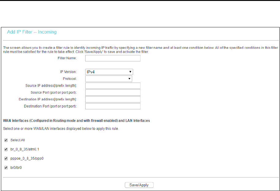
1. Click Add.
TD-W8960N User Guide
34
2. Then you will see the next screen as shown below.
3. Enter the Filter name for the rule, it is exclusive and must be filled.
4. Select the protocol in the drop-down list for the connection between the Source IP address
and Destination IP address.
5. Enter a Source IP Address in dotted-decimal notation format and then type Source Port (port
or port: port) in the text boxes separately.
6. Enter a Destination IP Address in dotted-decimal notation format and then type Destination
Port (port or port: port) in the text boxes separately.
7. Select one or more WAN/LAN interfaces displayed to apply this rule.
8. Click Save/Apply to save this entry.
Note:
When you add an IP Filtering entry, you must configure at least one condition on the preceding screen
except the Filter name. If you leave the Protocol blank, it means that the rule is effective to all
protocols, if you leave the Source IP Address and/or Destination IP Address blank, it suggests that all
Source IP Addresses and/or Destination IP Addresses are controlled by the rule, if you leave the
Source Port and/or Destination Port blank, it suggests that all Source Ports and/or Destination Ports
are controlled by the rule.
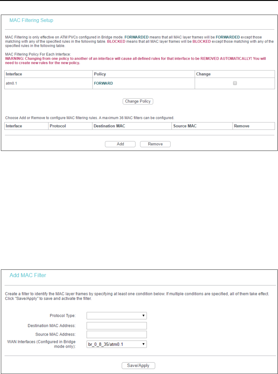
4.3.6.2 MAC Filtering
Go to Advanced Setup → Security → MAC Filtering, you can configure MAC Filtering rules. The
section allows you to control access to the internet by users on your local network based on their
MAC Address.
Note:
MAC Filtering is only effective on ATM PVC(s) configured in Bridge mode.
TD-W8960N User Guide
35
Change Policy: There are two policies for the MAC filters: FORWARDED and BLOCKED.
Select the Change checkbox and click Change Policy to change from one policy to another.
When you set FORWARDED, it means that all MAC layer frames will be forwarded except
those matching with any of the specified rules in the table. While BLOCKED means that all
MAC layer frames will be blocked except those matching with any of the specified rules in the
preceding table.
Add: Click Add, and then you can add a new MAC Filter in the next screen.
Remove: Select the checkbox in the table and click Remove, and then the corresponding
entry will be deleted in the table.
To add a MAC Filtering rule:
1. Click Add, and you will see the next screen as shown below.
2. Select Protocol Type in the drop-down list for the rule.
3. Enter Destination MAC Address and Source MAC Address in the text box.
4. Select the WAN interfaces from the drop-down list.
5. Click Save/Apply to save this entry.
TD-W8960N User Guide
36
4.3.7 Parental Control
Go to Advanced Setup → Parental Control, you can configure the Parental Control function. Time
Restriction allows you to control the internet activities of the children by restricting the time of
surfing. URL Filter limits the computers you choose to access certain websites. These two
features work independently.
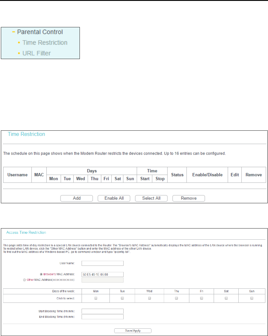
4.3.7.1 Time Restriction
This feature allows you add time of day restriction to a special device connected to the router.
To add a Time Restriction entry:
1. Click Add.
2. Enter the User Name of the LAN device connected to the router.
3. To restrict the device where the browser is running, select the Browser's MAC Address radio
button. The MAC Address has been automatically displayed in the text box. To restrict other
LAN devices, click Other MAC Address radio button and enter the MAC address of the other
LAN device.
4. Select the day to allow the rule to take effect in the table.
5. Enter the Start Blocking Time and End Blocking Time in the text box separately, and then the
device controlled will be unable to connect to the internet during that time.
TD-W8960N User Guide
37
6. Click Save/Apply to save this entry.
Note:
The Time Restriction will not work correctly before the time of the device is set in Management →
Internet Time.
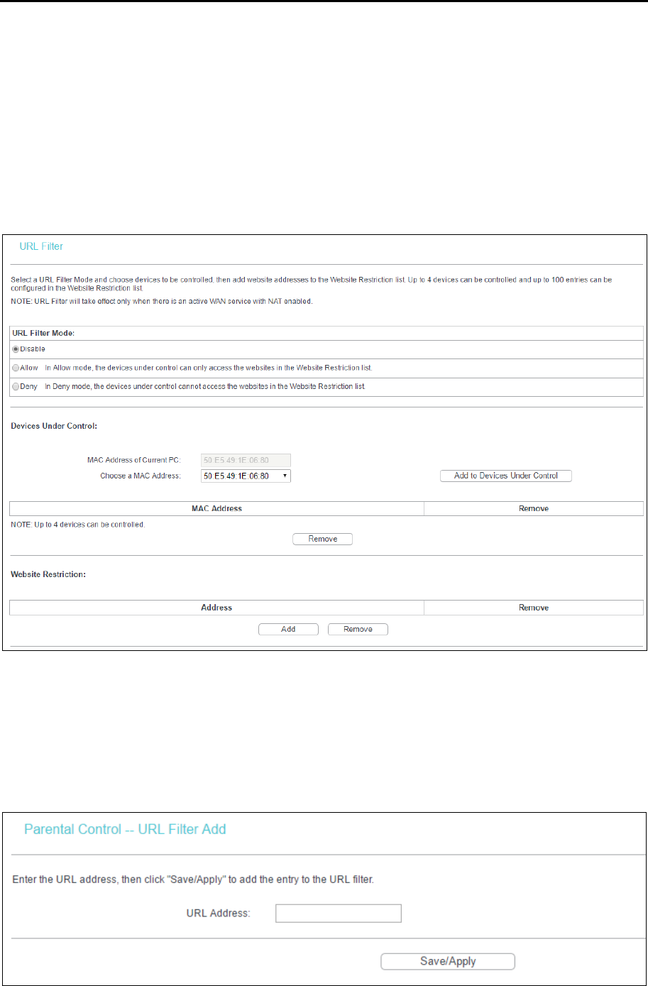
4.3.7.2 URL Filter
This feature allows you to configure the filter rules based on URL to control the computers in the
LAN to access the specified websites, and it is independent of Time Restriction feature.
To set up the URL Filter:
1. Check Allow or Deny. Here we take Deny for example.
2. Focus on the Devices Under Control section. Choose the MAC Address of the computer you
want to control and click Add to Devices Under Control.
3. Focus on the Website Restriction section. Click Add and then you will see the next screen, as
shown in the following picture. Enter a URL address such as a website, then click Save/Apply.
TD-W8960N User Guide
38
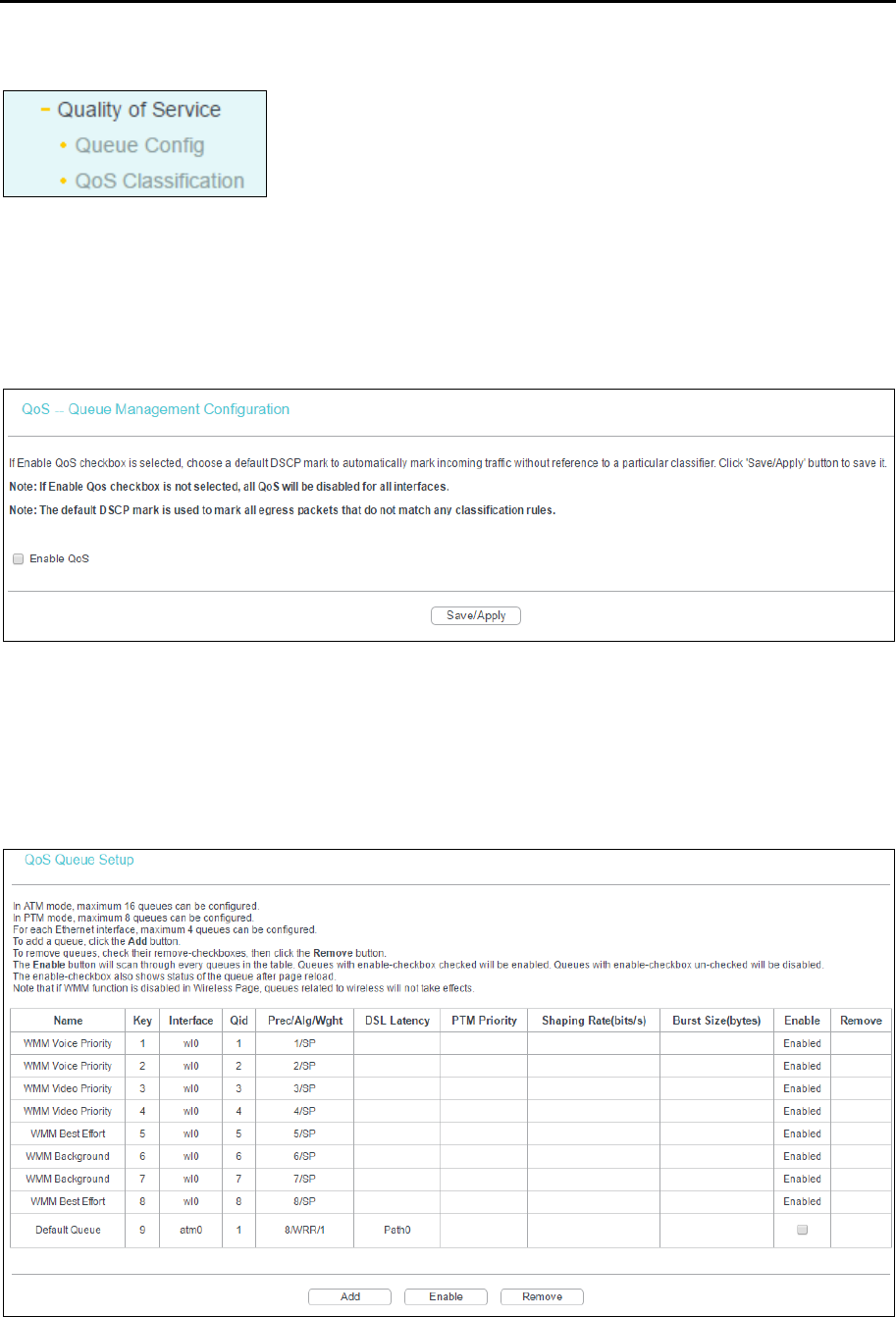
4.3.8 Quality of Service
Go to Advanced Setup → Quality of Service, you can enable QoS (Quality of Service) on the
screen shown below. QoS helps to prioritize data as it enters your router. By attaching special
identification marks or headers to incoming packets, QoS determines which queue the packets
enter, based priority. This is useful when there are certain types of data you want to give higher
priority, such as voice data packets give higher priority than Web data packets. This option will
provide better service of selected network traffic over various technologies.
Select the Enable QoS checkbox to enable all QoS for all interfaces, and click Save/Apply to save
the current configuration.
4.3.8.1 Queue Config
Go to Advanced Setup → Quality of Service → Queue Config, you can set up virtual servers on
the screen below.
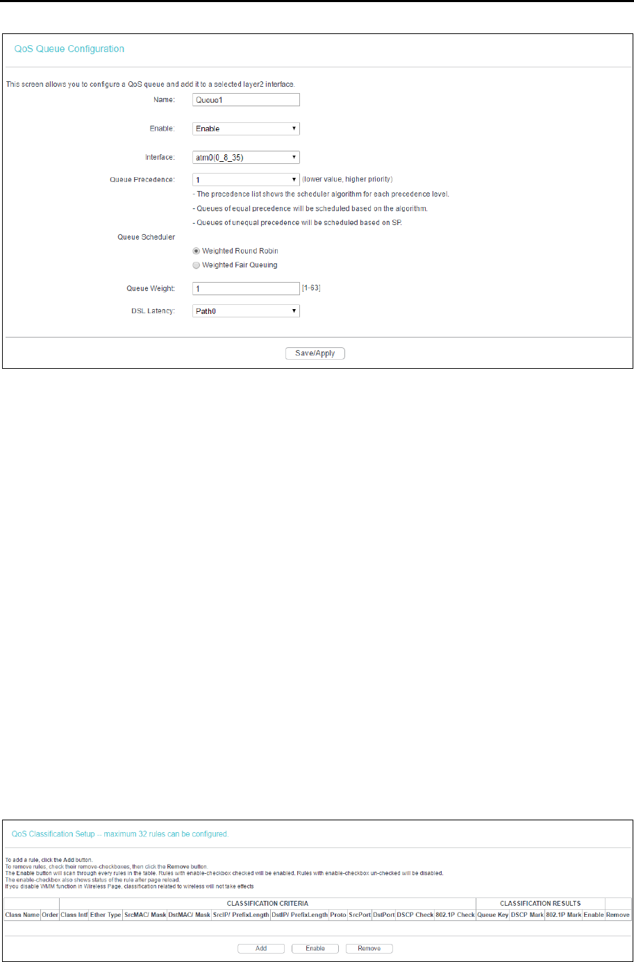
Click Add, and you can configure the QoS queue entry on the next screen.
TD-W8960N User Guide
39
Name: Set a name for the entry.
Enable: Select Enable option to take this entry effect.
Interface: Assigned a specific Wan Service for this QoS queue entry.
Precedence: Specify precedence for this QoS queue entry.
DSL Latency: Select latency path for the type of data transmission, only Path0 is available for
this router.
After you specify the condition, click Save/Apply to save the entry.
Note:
1) Lower integer values for precedence imply higher priority for this queue relative to others.
2) The queue entry configured here will be used by the classifier to place ingress packets
appropriately.
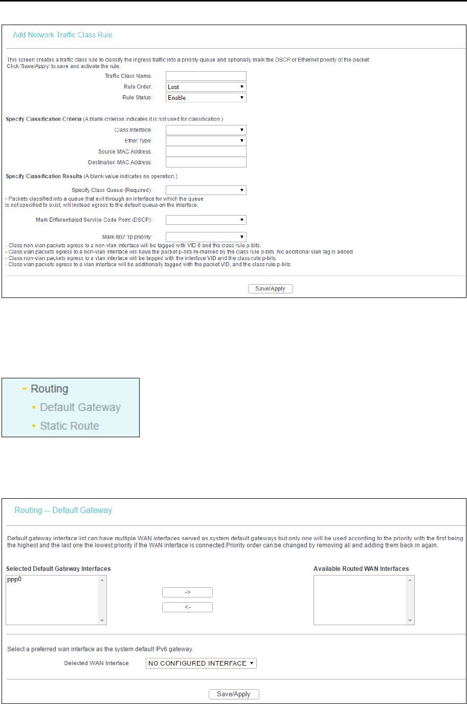
4.3.8.2 QoS Classification
This section will guide you to create a traffic class rule to classify the upstream traffic, assign
queue which defines the precedence and the interface and optionally overwrite the IP header
DSCP byte.
A rule consists of a class name and at least one condition below. All of the specified conditions in
this classification rule must be satisfied for the rule to take effect.
Click Add, and you can configure the QoS on the next screen.
TD-W8960N User Guide
40
After you specify the condition, click Save/Apply to save the entry.
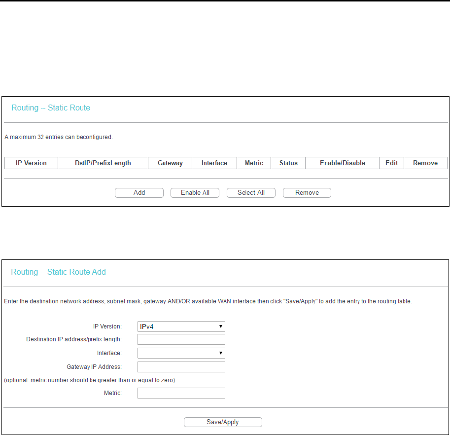
4.3.9 Routing
Go to Advanced Setup → Routing, it includes 2 menus: Default Gateway and Static Route. The
detailed descriptions are provided below.
4.3.9.1 Default Gateway
Go to Advanced Setup → Routing → Default Gateway, you can see the Default Gateway screen.
TD-W8960N User Guide
41
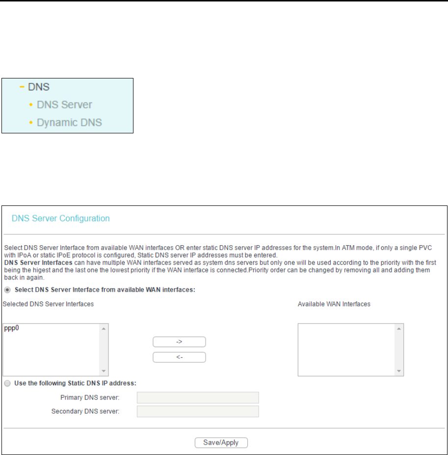
4.3.9.2 Static Route
Go to Advanced Setup → Routing → Static Route, you can see the Static Route screen and
configure the static routes. A static route is a pre-determined path that network information must
travel to reach a specific host or network.
To add static routing entries:
1. Click Add, and you will see the screen as shown below.
2. Enter the following data:
IP Version: Select the version of IP.
Destination IP Address/prefix length: The Destination IP Address is the address of the
network or host that you want to assign to a static route.
Interface: Select the Interface name in the text box, or else, the default Use Interface will be
adopted for the Static Route.
Gateway IP Address: If you select the IPoE or IPoA mode for Interface, the screen above will
display this item, you should type the Gateway address correctly, and the other option for
Interface will adopt the default Gateway address for the Static Route.
3. Click Save/Apply to save the entry.
To remove a static routing entry:
1. Select the Remove checkbox according to the entry.
2. Click Remove, and the entry will be deleted.
Note:
Gateway IP address should be correctly configured if IP based Interface (IPoE, IPoA) is selected.
TD-W8960N User Guide
42
4.3.10 DNS
When you select the connection type PPPoE, PPPoA or IPoA for WAN configuration, you will see
the DNS menu in the Web-based Utility. It includes DNS Server and Dynamic DNS submenus.
4.3.10.1 DNS Server
Go to Advanced Setup → DNS → DNS Server, and you can see the DNS Server Configuration
screen.
For PPPoA, PPPoE enabled PVC(s), please select the Select DNS Server Interface from available
WAN interfaces checkbox, this modem router will accept automatically the first received DNS
assignment from the selected configured WAN interface during the connection establishment.
For single PVC with IPoA, static IPoE protocol, please select the Use the following Static DNS IP
address checkbox, and enter the primary and /or optional secondary DNS server IP addresses
provided by your ISP.
Click Save/ Apply to save the new configuration.
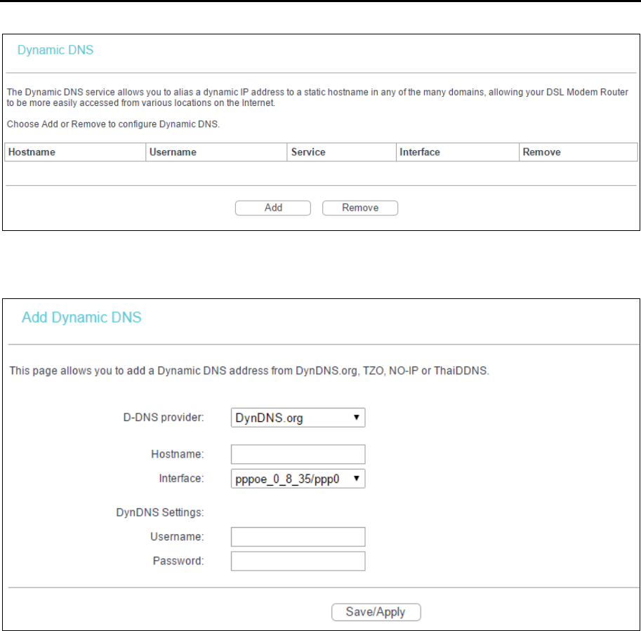
4.3.10.2 Dynamic DNS
Go to Advanced Setup → DNS → Dynamic DNS, you can configure the Dynamic DNS on this
screen.
The modem router offers a Dynamic Domain Name System (DDNS) feature. DDNS lets you
assign a fixed host and domain name to a dynamic Internet IP Address. The Dynamic DNS service
allows you to alias a dynamic IP address to a static hostname in any of the many domains,
allowing your modem router to be more easily accessed from various locations on the internet.
TD-W8960N User Guide
43
To add a DDNS entry:
1. Click Add, and then you can set the DDNS in the next screen.
2. Select D-DNS provider in the drop-down list.
3. Enter the Hostname of the DNS Server, and select the corresponding Interface for the DDNS,
you can leave it default.
4. Type the User Name and Password for your DDNS account.
Click Save/Apply to make the settings effective.
TD-W8960N User Guide
44
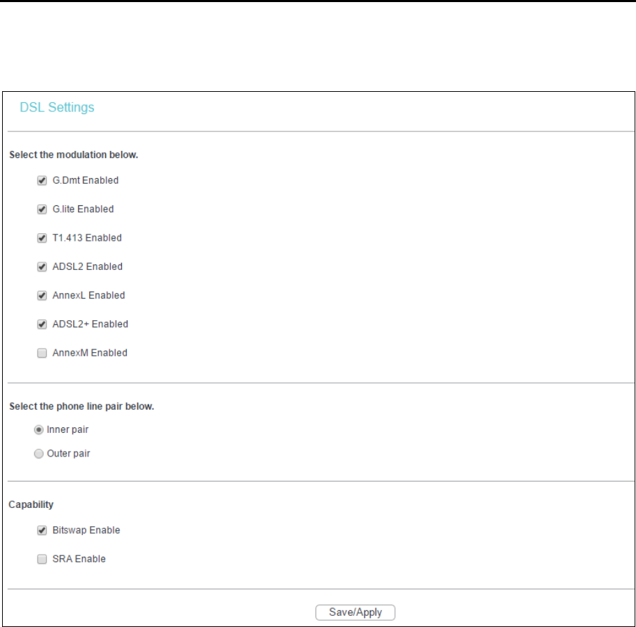
4.3.11 DSL
Go to Advanced Setup → DSL, you can configure the DSL Settings.
You can select the modulation type, phone line pair and the capability of Bitswap or SRA. After
you set them up, click Save/Apply to save the configurations.
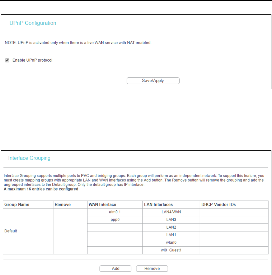
4.3.12 UPnP
Go to Advanced Setup → UPnP, you can Enable or Disable the UPnP (Universal Plug and Play)
protocol on the screen.
UPnP (Universal Plug and Play) is a distributed, open networking standard that uses TCP/IP for
simple peer-to-peer network connectivity between devices. An UPnP device can dynamically join
a network, obtain an IP address, convey its capabilities and learn about other devices on the
network. In turn, a device can leave a network smoothly and automatically when it is no longer in
use. UPnP broadcasts are only allowed on the LAN.
TD-W8960N User Guide
45
Select the checkbox and click Save/Apply to enable the UPnP function.
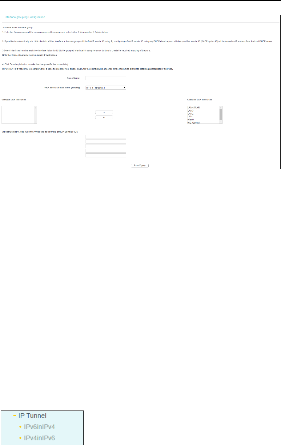
4.3.13 Interface Grouping
Go to Advanced Setup → Interface Grouping, you can configure multiple ports to PVC and
bridging groups to perform as an independent network.
To support this feature, you must create mapping groups with appropriate LAN and WAN
interfaces using the Add button. The Remove button will remove the grouping and add the
ungrouped interfaces to the Default group. Only the default group has IP interface.
To create a new interface group:
1. Click Add. You can add a new interface group in the next screen.
TD-W8960N User Guide
46
2. Enter a unique name for Group.
3. Select the Interface which you want to use from the drop-down list.
Note:
If you like to automatically add LAN clients to a WAN Interface in the new group add the DHCP vendor
ID string. By configuring a DHCP vendor ID string any DHCP client request with the specified vendor ID
(DHCP option 60) will be denied an IP address from the local DHCP server.
4. Select interfaces from the available interface list and add it to the grouped interface list using
the arrow buttons to create the required mapping of the ports.
Note:
These clients may obtain public IP addresses.
5. Click Save/Apply to make the entry effective immediately.
Note:
If a vendor ID is configured for a specific client device, please REBOOT the client device attached to
the modem to allow it to obtain an appropriate IP address.
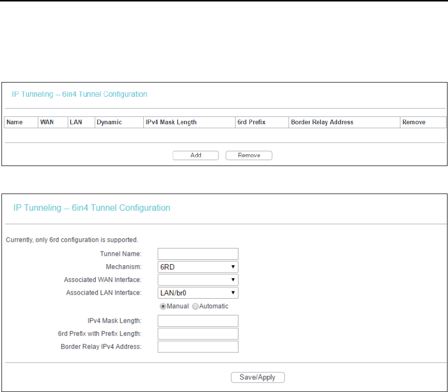
4.3.14 IP Tunnel
IPv6 tunnel is a kind of transition mechanism to enable IPv6-only hosts to reach IPv4 services and
to allow isolated IPv6 hosts and networks to reach each-other over IPv4-only infrastructure before
IPv6 completely supplants IPv4. It is a temporary solution for networks that do not support native
dual-stack, where both IPv6 and IPv4 run independently.
Go to Advanced Setup → IP Tunnel, it includes two menus: IPv6inIPV4 and IPv4inIPv6, The
detailed descriptions are provided below.
TD-W8960N User Guide
47
4.3.14.1 IPv6inIPv4
Go to Advanced Setup → IP Tunnel → IPv6inIPv4. You can see the 6in4 tunnel configuration
screen, this screen allows you to configure the static routes.
Click Add, and you can configure the 6in4 tunnel on the next screen.
Mechanism: 6RD, this type is used in the situation that your WAN connection is IPv4 while
LAN connection is IPv6.
Associated WAN Interface: Select a WAN connection from the drop-down list. Only the
connected WAN connections can be shown in the drop-down list.
Associated LAN Interface: Select a LAN connection from the drop-down list. Only the
connected LAN connections can be shown in the drop-down list.
IPv4 Mask Length: The length of the selected WAN connection’s IPv4 mask.
6rd Prefix with Prefix Length: The length of the 6rd prefix.
Border Relay IPv4 Address: The IPv4 address of the border relay router of 6RD tunnel.
Click Save/Apply to make the configuration take effect.
Note:
In this type, there should not have any IPv6 WAN connections. If there are IPv6 WAN connections, the
page will prompt you to delete all the IPv6 WAN connections.
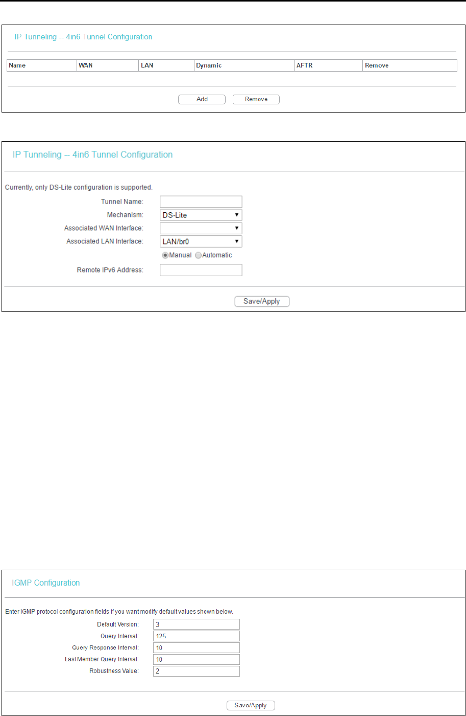
4.3.14.2 IPv4inIPv6
Go to Advanced Setup → IP Tunnel → IPv4inIPv6. You can see the 4in6 tunnel configuration
screen, this screen allows you to configure the static routes.
TD-W8960N User Guide
48
Click Add, and you can configure the 6in4 tunnel on the next screen as shown below.
Mechanism: DS-Lite, this type is used in the situation that your WAN connection is IPv6 while
LAN connection is IPv4.
Associated WAN Interface: Select a WAN connection from the drop-down list. Only the
connected WAN connections can be shown in the drop-down list.
Associated LAN Interface: Select a LAN connection from the drop-down list. Only the
connected LAN connections can be shown in the drop-down list.
AFTR: Enter the IPv6 address of the remote node.
Click Save/Apply to make the configuration take effect.
Note:
In this type, there should not be any IPv4 WAN connections. If there are IPv4 WAN connections, the
page will prompt you to delete all the IPv4 WAN connections.
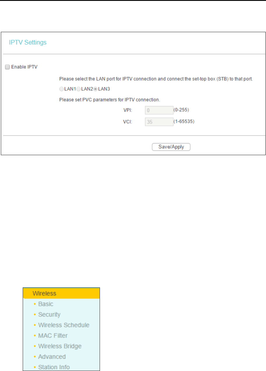
4.3.15 Multicast
Go to Advanced Setup → Multicast, you can configure the IGMP protocol on the screen.
Click Save/Apply to make the settings effective.
TD-W8960N User Guide
49
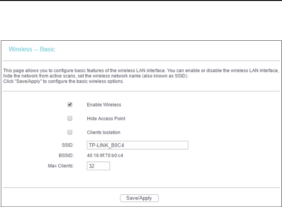
4.4 IPTV
Enable IPTV: Check this box to enable IPTV. If you enable IPTV, please make sure the
following settings are correct.
VPI (0-255): Identifies the virtual path between endpoints in an ATM network. The valid range
is from 0 to 255. Please input the value provided by your ISP.
VCI (1-65535): Identifies the virtual channel endpoints in an ATM network. The valid range is
from 1 to 65535 (1 to 31 is reserved for well-known protocols). Please input the value
provided by your ISP.
Click Save/Apply to make the settings effective.
4.5 Wireless
Go to Wireless, there are six submenus to configure Wireless LAN settings. Click any of them, and
you will be able to configure the corresponding function. The detailed explanations for each
submenu are provided below.
TD-W8960N User Guide
50
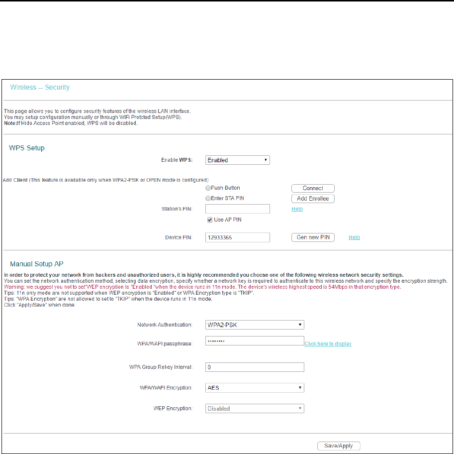
4.5.1 Basic
Go to Wireless → Basic, you can configure the basic settings for wireless networking.
This page allows you to configure basic features of the wireless LAN interface. You can enable or
disable the wireless LAN interface, hide the network from active scans and set the wireless
network name (also known as SSID).
Enable Wireless: If you want to use wireless features, you must select “Enable Wireless”. If
you deselect “Enable Wireless” option, the wireless network will be disabled.
Hide Access Point: When wireless clients survey the local area for wireless networks to
associate with, you can select this option to avoid being surveyed.
Clients Isolation: Select this option to enable AP isolation function so that stations associated
to the AP will not be able to communicate with each other.
SSID: SSID (Wireless network name) shared among all points in a wireless network. The SSID
must be identical for all devices in the wireless network. It is case-sensitive and must not
exceed 32 characters (use any of the characters on the keyboard). Make sure this setting is the
same for all stations in your wireless network. Type the desired SSID in the space provided.
BSSID: Show the MAC address of the router’s wireless network.
Max Clients: The maximum number of wireless clients that can connect to the router.
Click Save/Apply to make the settings effective.
TD-W8960N User Guide
51
4.5.2 Security
Go to Wireless → Security, you can configure security features of the wireless LAN interface by
manually setting the network authentication or through WPS (Wi-Fi Protected Setup) method.
4.5.2.1 WPS Setup
This section will guide you to add a new wireless device to an existing network quickly by WPS (or
called QSS) method.
Note:
1) This feature is available only when WPA2-PSK or OPEN mode is configured.
2) To build a successful connection by WPS, you should also do the corresponding configuration of the
new device for WPS function meanwhile.
I. By PBC
If the wireless adapter supports WPS and the Push Button Configuration (PBC) method, you can
add it to the network by PBC with the following two methods.
TD-W8960N User Guide
52
Method One: Hardware push button.
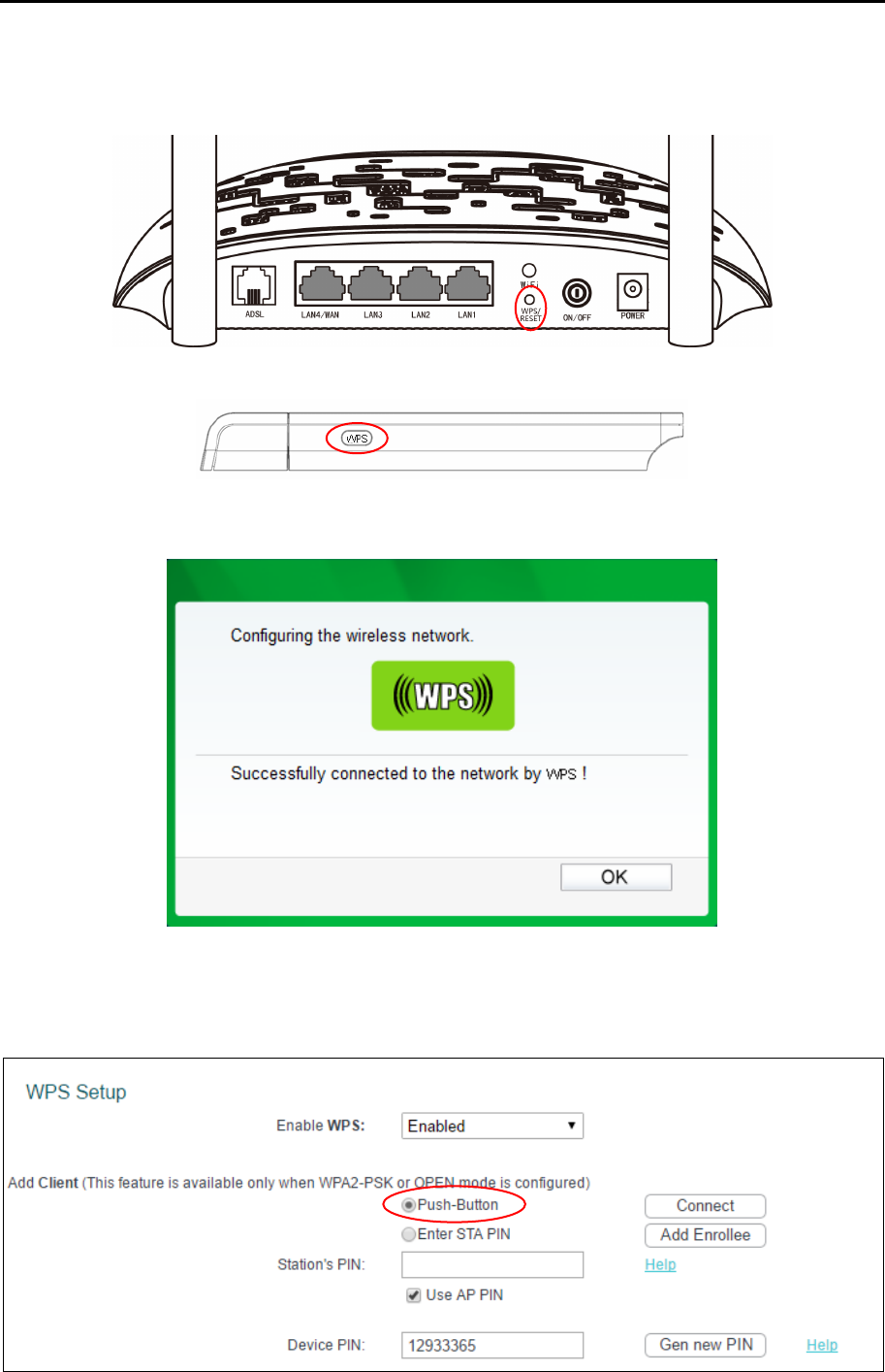
Step 1: Press the WPS/RESET button on the back panel of the router.
Step 2: Press and hold the WPS button of the adapter (if it has one) for 2 or 3 seconds.
Step 3: Wait for a while until the following screen of adapter appears. Click OK to complete the
WPS configuration.
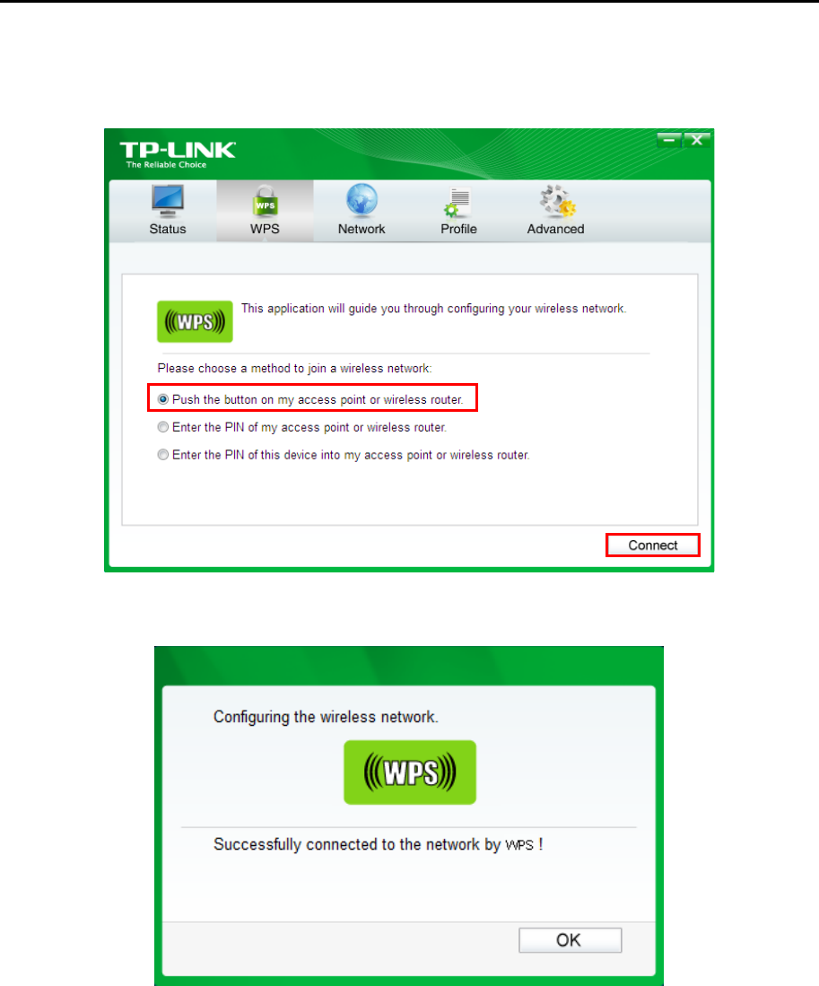
Method Two: Client’s configuration utility
Step 1: Click Push-Button, you will see the screen as shown below. Then click Connect.
TD-W8960N User Guide
53
Step 2: For the configuration of the wireless adapter, please choose Push the button on my
access point or wireless router in the configuration utility of the WPS as below, and click
Connect.
Step 3: Wait for a while until the following screen appears. Click OK to complete the WPS
configuration.
II. By PIN
If the new device supports Quick Security Setup and the PIN method, you can add it to the
network by PIN with the following two methods.
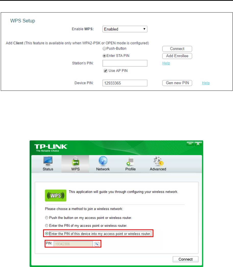
Method One: Enter the PIN of wireless adapter into my router.
Step 1: Select the Enter STA PIN radio box and enter the PIN code of the wireless adapter in the
field under as shown below. Then click Add Enrollee.
TD-W8960N User Guide
54
Note:
The PIN of the adapter is always displayed on the WPS configuration screen.
Step 2: For the configuration of the wireless adapter, please choose Enter the PIN of this device
into my access point or wireless router in the configuration utility of the WPS as below,
and click Connect.
Note:
In this example, the default PIN code of this adapter is 19342306 as the preceding figure shows.
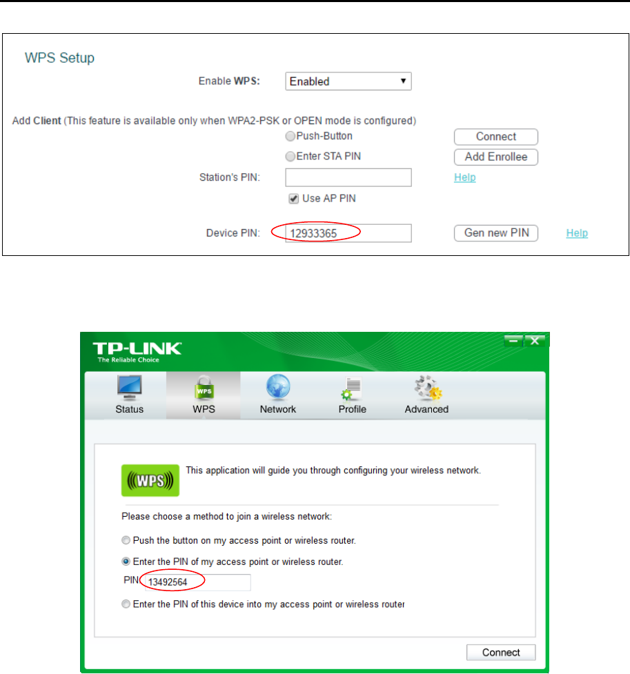
Method Two: Enter the PIN of my router into the wireless adapter.
Step 1: Select Use AP PIN and get the Device PIN generated by the router as shown below. You
can click Gen New PIN to get a new PIN code for router.
TD-W8960N User Guide
55
Step 2: For the configuration of the wireless adapter, please choose Enter the PIN of my access
point or wireless router in the configuration utility of the WPS as below, and enter the PIN
code of the router into the field after Device PIN. Then click Connect.
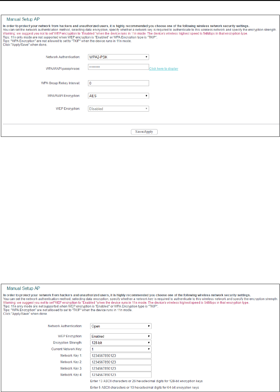
4.5.2.2 Manual Setup AP
Follow the instructions below to configure security features of the wireless LAN interface manually.
You can set the network authentication method, select data encryption, specify whether a network
key is required to authenticate to this wireless network and specify the encryption strength.
TD-W8960N User Guide
56
Network Authentication: Select an authentication type from the drop-down list. Options
available are: Open, Shared, WPA, WPA-PSK, WPA2, WPA2-PSK, Mixed WPA2/WPA, and
Mixed WPA2/WPA-PSK.
Note:
For most users, it is recommended to use the default Wireless LAN Performance settings. Any changes
made to these settings may adversely affect your wireless network. Under certain circumstances,
changes may benefit performance. Carefully consider and evaluate any changes to these wireless
settings.
1. WEP
WEP is a basic encryption method offering two levels of encryption, 64-bit and 128-bit encryption.
To configure the WEP encryption, there are two ways.
•
Keep the Network Authentication of Open (insecure) and select Enabled from the WEP
Encryption drop-down list. Open (insecurity) with WEP encryption disable allows any wireless
station to associate with the access point.
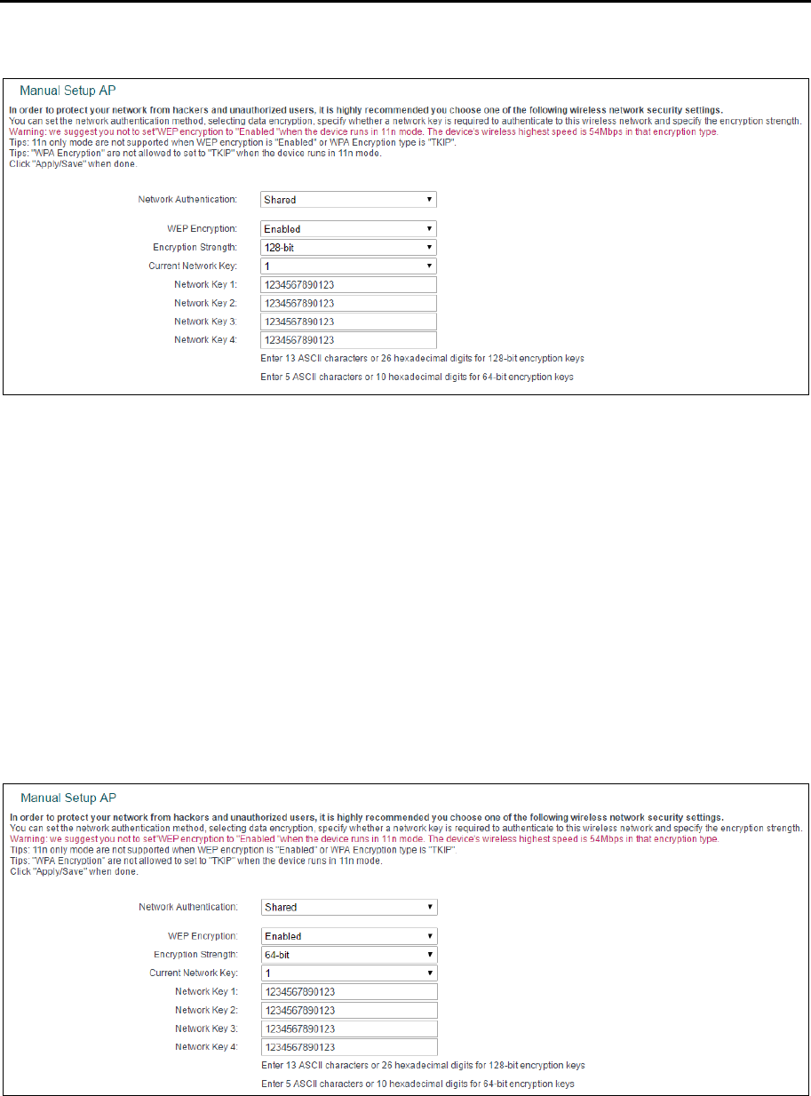
•
Select Shared from the Network Authentication drop-down list. Shared must enable WEP
encryption. Network using Open or Shared authentication with WEP encryption only allows
stations using the same network key encryption to associate with it. Follow the instructions
below to configure the Shared Keys.
TD-W8960N User Guide
57
Encryption strength: Select the appropriate level of encryption, 64-bit or 128-bit.
Current Network Key: To indicate which WEP key to use, select a transmission key number.
Network Key 1-4: If you want to manually enter the WEP keys, then enter them in the network
Key 1-4 fields.
Configure WEP Settings
1. Select Shared from the Network Authentication drop-down list. The menu will change to offer
the appropriate settings.
2. Select 64-bit from the WEP Encryption drop-down list.
3. Select 1 from Current Network Key drop-down list.
4. Type in the password in the Network Key 1 field.
5. Click Save/Apply to save the new configuration.
Note:
All parameters in the figure above are used for demonstration.
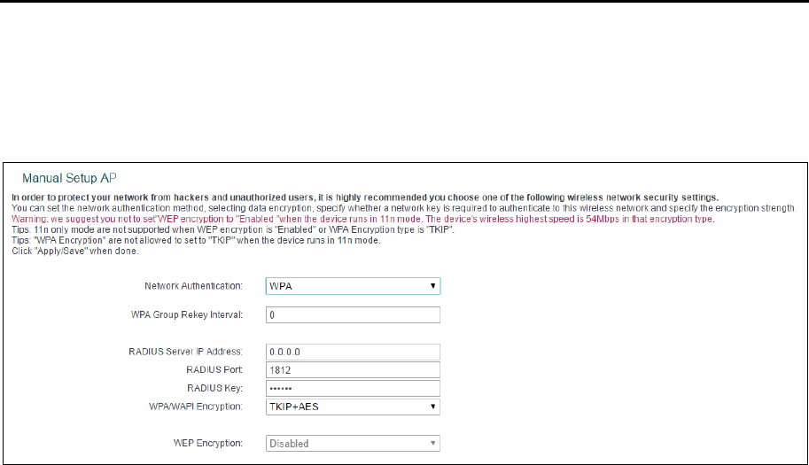
TD-W8960N User Guide
58
2. WPA
WPA security for wireless communication has been developed to overcome some of the
shortcomings of WEP. WPA combines the key generation with the authentication services of a
RADIUS server.
WPA Group ReKey Interval: Enter the Key Renewal period, which tells the router how often it
should change encryption keys.
RADIUS Server IP Address: The IP address of the RADIUS server.
RADIUS Port: The port of the RADIUS server. The default number is 1812.
RADIUS key: The password of the RADIUS Server.
WPA/WPAI Encryption: Select the encryption you want to use: AES or TKIP+AES (AES is an
encryption method stronger than TKIP).
Configure WPA settings
1. Select WPA from the Network Authentication drop-down list. The menu will change to offer the
appropriate settings.
2. Change the WPA Group Rekey Interval as desired.
3. Type in the IP address of the RADIUS server used in the RADIUS Server IP Address field.
4. Change the RADIUS Port if necessary.
5. Type in the password in the RADIUS Key field.
6. Use the default setting TKIP+AES of WPA/WPAI Encryption.
7. Click Save/Apply to save the new configuration.
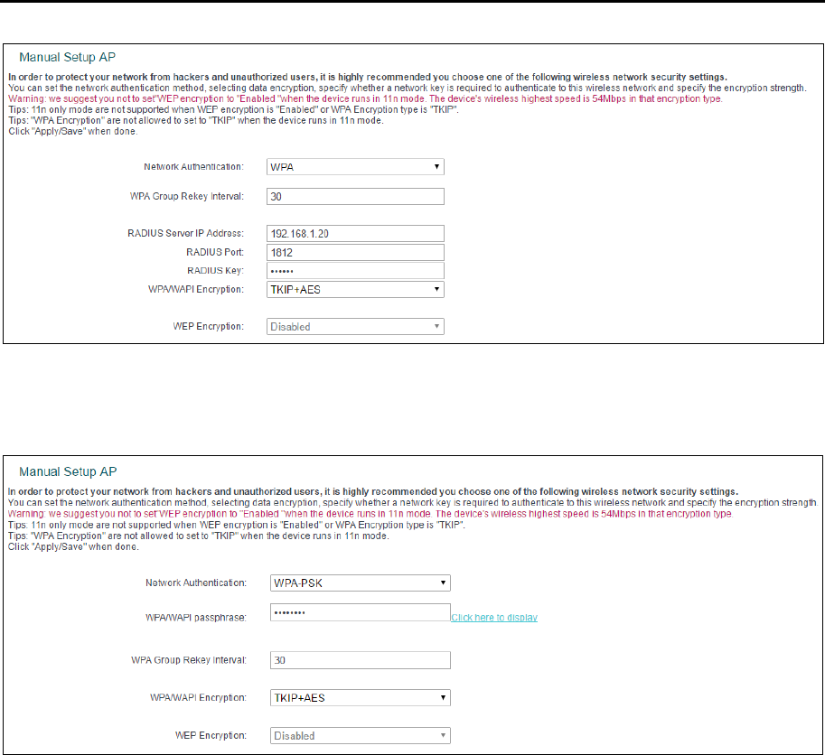
TD-W8960N User Guide
59
3. WPA-PSK
WPA-PSK requires a shared key and does not use a separate server for authentication. PSK keys
can be ASCII or Hex type.
WPA/WAPI passphrase: WPA/WAPI passphrase is also called Wireless Network Key. In this
field, enter the key shared by the router and your other network devices. It must have 8-63
ASCII characters or 8-64 Hexadecimal digits.
Click here to display: Click it to show you the WPA Pre-Shared Key.
Configure WPA-PSK settings
1. Select WPA-PSK. The menu will change to offer the appropriate settings as the picture show
above.
2. WPA-Personal requires a shared key. Type the key in the space provided. PSK keys can be
ASCII or Hex type.
3. Change the Group Key Interval as desired or use the default setting.
4. Click Save/Apply to save the new configuration.
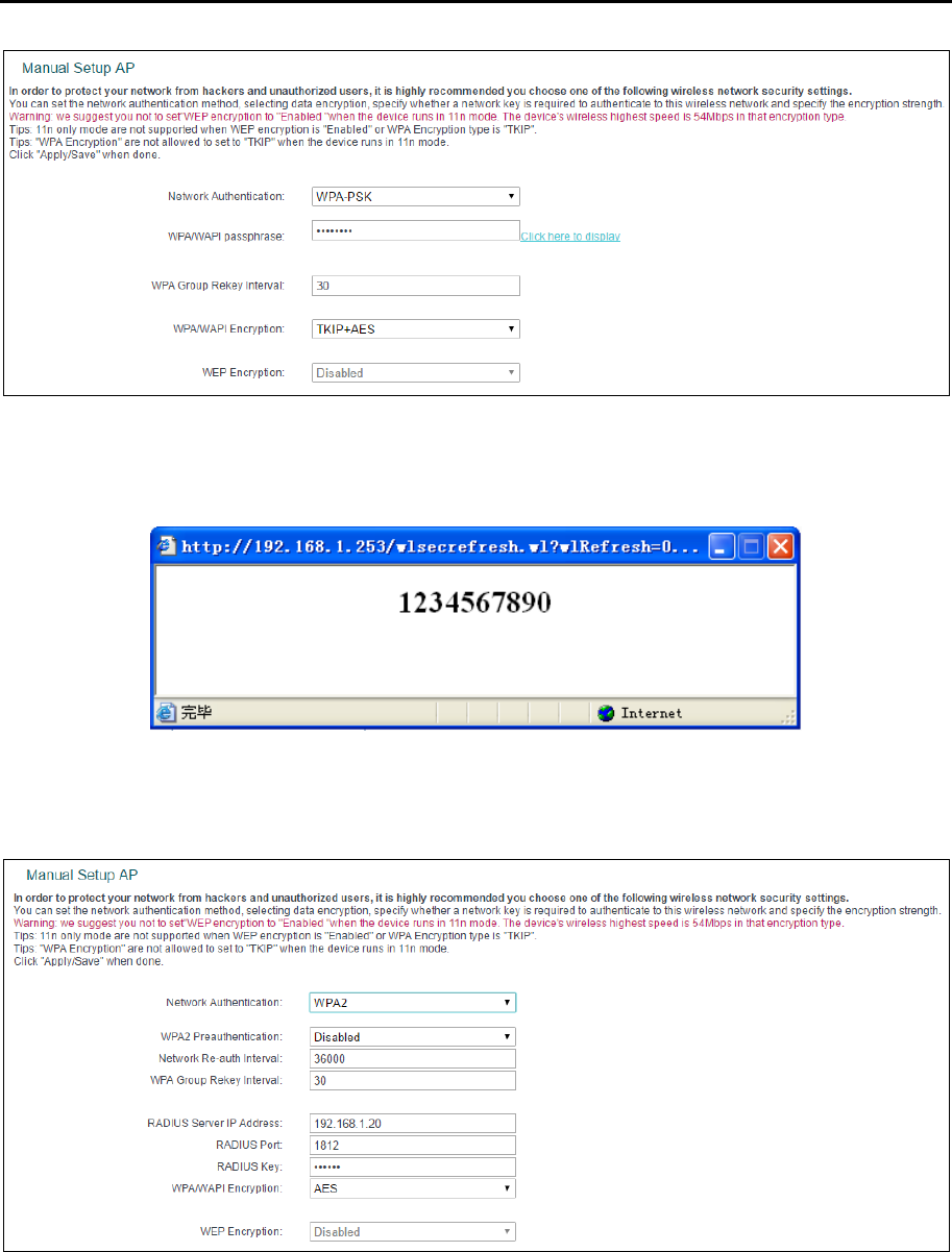
TD-W8960N User Guide
60
Note:
If you click the option Click here to display, a window will pop-up and show the password you have set.
In addition, it won't show the blank characters in both ends of the password phrase.
4. WPA2
To configure WPA2, select the WPA2 option from the drop-down list. The menu will change to
offer the appropriate settings. The steps of these settings are similar to WPA settings.
WPA2 Preauthentication: Select Enable from the drop-down list. Stations will authenticate
with the AP during the scanning process, and once association is required, the station has
been already authenticated.
Network Re-auth Interval: Enter a value in seconds as the frequency interval to enable
periodic Network Re-authentication function, while leave it blank or enter “0” to disable it.
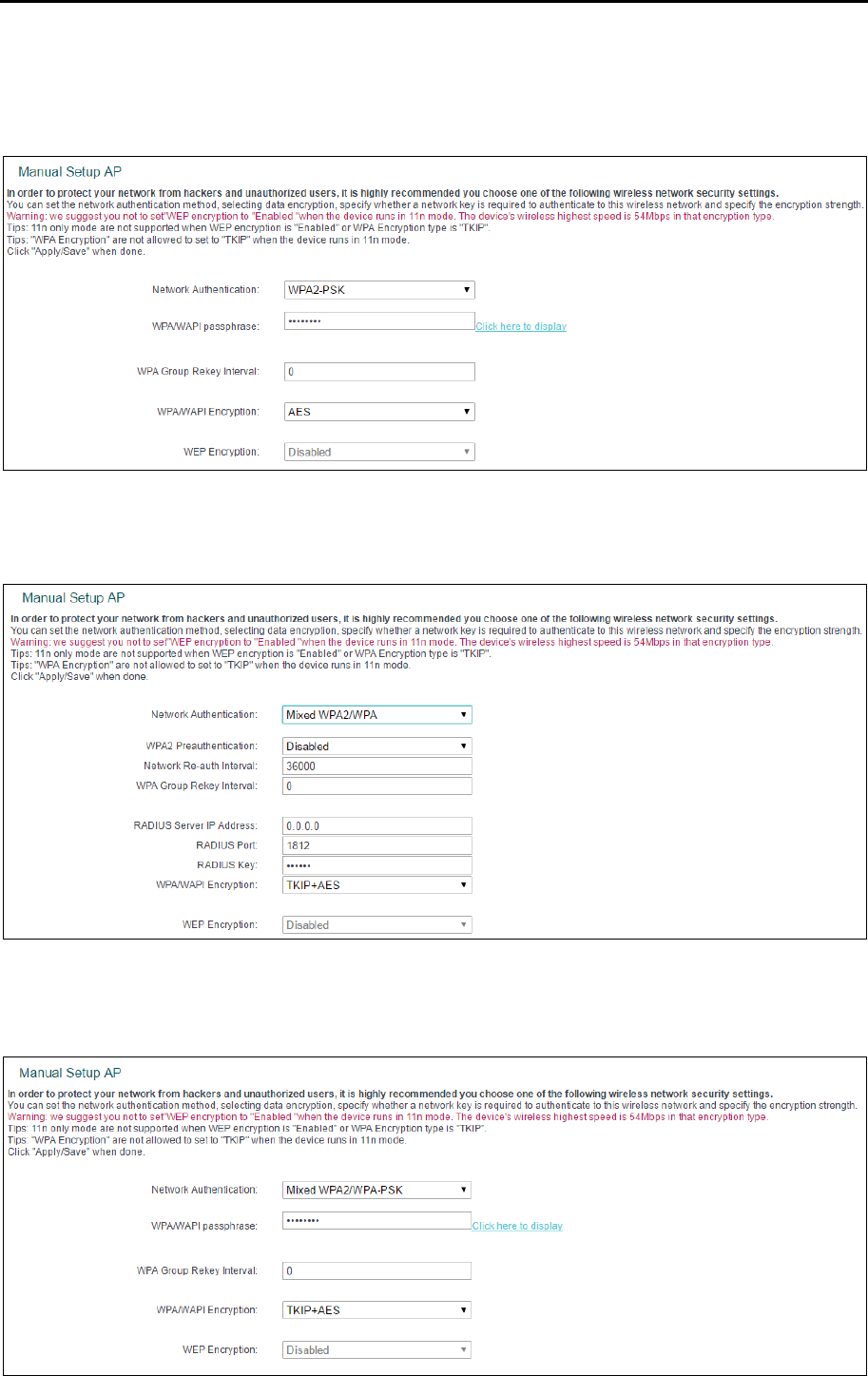
TD-W8960N User Guide
61
5. WPA2 -PSK
To configure WPA2-PSK settings, select the WPA2 -PSK option from the drop-down list. WPA2
-PSK requires a shared key and does not use a separate server for authentication. PSK keys can
be ASCII or Hex type.
6. Mixed WPA2/WPA
To configure Mixed WPA2/WPA settings, select the Mixed WPA2/WPA option from the drop-down
list. The steps to these settings are similar to those for WPA-PSK.
7. Mixed WPA2/WPA -PSK
To configure Mixed WPA2/WPA -PSK settings, select the Mixed WPA2/WPA -PSK option from the
drop-down list. The steps of this setting are the same with WPA-PSK.
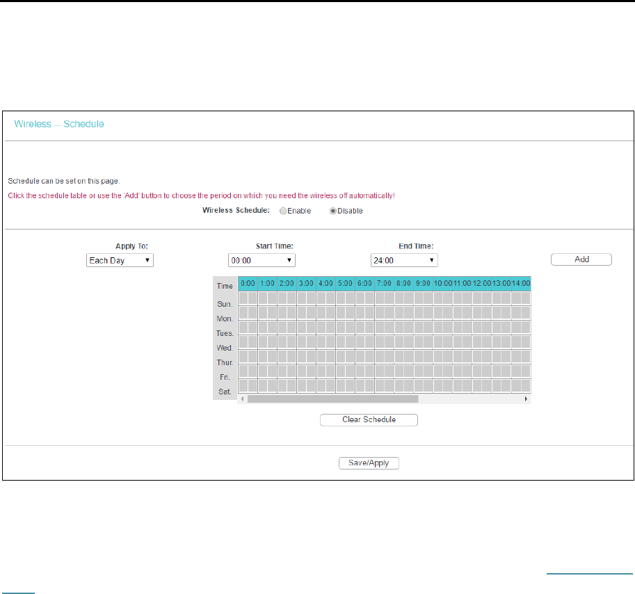
TD-W8960N User Guide
62
4.5.3 Wireless Schedule
Go to menu Wireless → Wireless Schedule, you can configure the Task Schedule as shown
below.
Note:
The time you set is the period you need the wireless off.
Before configuring the wireless schedule, please set system time first which refer to 4.8.5 Internet
Time, then you can enable or disable Wireless Schedule.
Apply To: Select the day or days you need the wireless off.
Start Time, End Time: You can select all day-24 hours or you may enter the Start Time and
End Time in the corresponding field.
Add: Click to add your selected time to the below table.
Click Clear Schedule to clear your settings in the table.
Click Save to complete the settings.
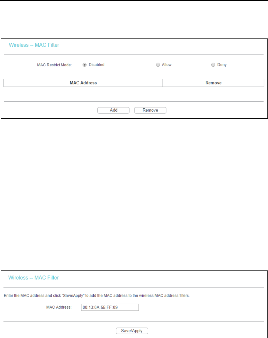
TD-W8960N User Guide
63
4.5.4 MAC Filter
Go to Wireless → MAC Filter, you will see the screen of MAC Filter settings.
Wireless access can be filtered by using the MAC addresses of the wireless devices transmitting
within your network’s RADIUS. To filter wireless users by MAC Address, either permitting or
blocking access. If you do not wish to filter users by MAC Address, select Disabled.
Disabled: Select this option to disable MAC Filter function.
Allow: Select this option to enable MAC Filter function that allow wireless access by the
devices listed on this screen.
Deny: Select this option to enable MAC Filter function that block wireless access from the
devices listed on this screen.
Add: Click this button to add the MAC Address.
Remove: Select the item of the MAC Address and click this button to remove it.
When you click Add, the pop-up picture shown below, and then you can type the MAC Address in
the MAC Address field.
Note:
The form of MAC Address must be “xx:xx:xx:xx:xx:xx”, like “00:13:0A:55:FF:09”.
Click Save/Apply to save the changes.
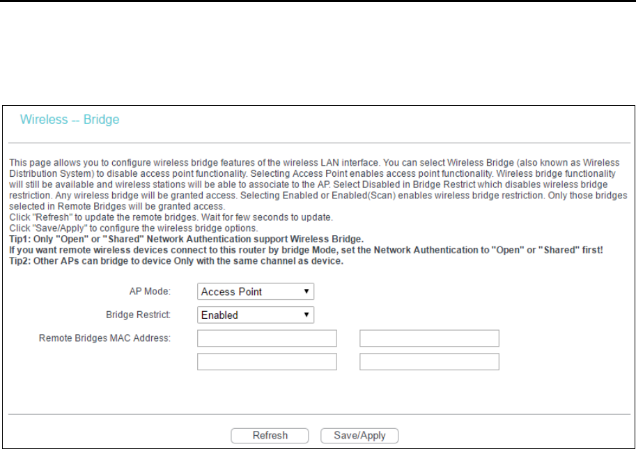
TD-W8960N User Guide
64
4.5.5 Wireless Bridge
Go to Wireless → Wireless Bridge, you can configure wireless bridge features of the wireless LAN
interface.
AP Mode: Select an AP Mode from the drop-down list. Options available are: Access Point
and Wireless Bridge.
• Access Point: Select this option to allow wireless stations including AP clients to access.
• Wireless Bridge: Also known as WDS (Wireless Distribution System), it will bridge the
wireless stations in bridge mode.
Bridge Restrict:
• Disabled: Select this option to disables wireless bridge restriction, that any wireless bridge
will be granted access.
• Enabled: Select this option to enable wireless bridge restriction, please enter the MAC
address of the Remote Bridges that you want to connect with, and only these Remote
Bridges are granted access.
• Enabled (Scan): Select this option to enables wireless bridge restriction, and it will scan
the environment for APs that exist around the device. Only those selected AP will be
granted access.
• Refresh: Click to scan and display the APs.
Note:
1) Only Open or Shared authentication method support wireless bridge, you should choose Wireless
→ Security to change authentication method to “open” or “shared” mode first.
2) The AP that our router bridges to also should input our router's BSSID (MAC Address).
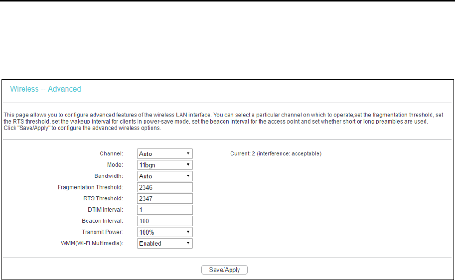
TD-W8960N User Guide
65
4.5.6 Advanced
Go to Wireless → Advanced, you will see the screen of Wireless Advanced settings shown as
below.
Channel: Select the channel you want to use from the drop-down List. This field determines
which operating frequency will be used. It is not necessary to change the wireless channel
unless you notice interference problems with another nearby access point.
Mode: In the drop-down list you can select 11b, 11g, 11bg, 11bgn and 11n only. “11bgn”
allows both 802.11b, 802.11g and 802.11n wireless stations to connect to the router.
Bandwidth: Select the Bandwidth you want to use from the drop-down List. If bigger
bandwidth is selected, device could transmit and receive data with higher speed.
Fragmentation Threshold: This value specifies the maximum size for a packet before data
is fragmented into multiple packets. If you experience a high packet error rate, you may
slightly increase the Fragmentation Threshold. Setting the Fragmentation Threshold too low
may result in poor network performance. Only minor reduction of the default value is
recommended. In most cases, it should remain at its default value of 2346.
RTS Threshold: Should you encounter inconsistent data flow, only minor reduction of the
default value 2347 is recommended. If a network packet is smaller than the preset RTS
threshold size, the RTS/CTS mechanism will not be enabled. The router sends Request to
Send (RTS) frames to a particular receiving station and negotiates the sending of a data
frame. After receiving an RTS, the wireless station responds with a Clear to Send (CTS)
frame to acknowledge the right to begin transmission. This mechanism can provide you a
quiet communication channel by notifying other stations not to send packet for a period of
time. In most cases, keep its default value of 2347.
DTIM Interval: This value, between 1 and 255, indicates the interval of the Delivery Traffic
Indication Message (DTIM). A DTIM field is a countdown field informing clients of the next
window for listening to broadcast and multicast messages. The countdown unit is measured
by the amounts of beacon frames received. When the router has buffered broadcast or
multicast messages for associated clients, it sends the next DTIM with a DTIM Interval value.
Its clients hear the beacons and awaken to receive the broadcast and multicast messages.
The default value is 1.
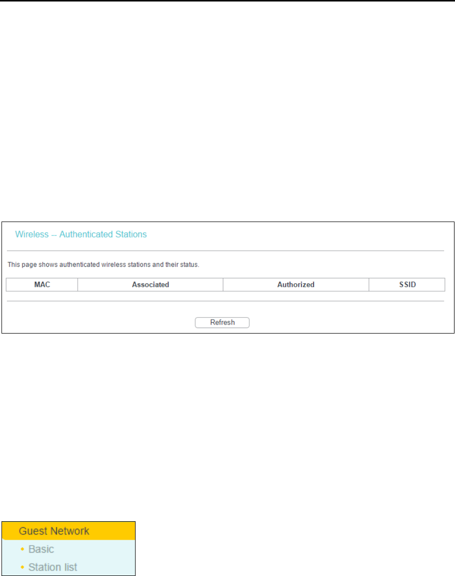
TD-W8960N User Guide
66
Beacon Interval: Enter a value between 20-1000 milliseconds. The beacons are the packets
sent by the modem router to synchronize a wireless network. Beacon Interval value
determines the time interval of the beacons. The default value is 100.
Transmit Power: This option will allow you to configure the wireless transmit power. High
transmit power will extend the wireless signal range of the device and make the signal
transmit more legible. Low transmit power with the smaller wireless signal range that will
decrease the probability of interrupt by other Wi-Fi device.
WMM (Wi-Fi Multimedia): This function can guarantee the packets with high-priority
messages being transmitted preferentially. It is strongly recommended.
4.5.7 Station info
Go to Wireless → Station Info, you will see the screen of Authenticated Stations setting shown as
below.
This page shows authenticated wireless stations and their status.
MAC: Displays the connected wireless station's MAC address.
Associated: Displays whether the wireless station has associated with the access point.
Authorized: Displays the information of Authentication.
SSID: Displays the connected wireless station's SSID.
You cannot change any of the values on this page. To update this page and to show the current
connected wireless stations, click Refresh.
4.6 Guest Network
There are two submenus under the Guest Network menu: Basic and Station list. Click any of them,
and you will be able to scan or configure the corresponding function. The detailed explanations for
each submenu are provided below.
4.6.1 Basic
Go to Guest Network → Basic, you can create a separate network for your guests without allowing
them to access your main network and the computers connected to it.
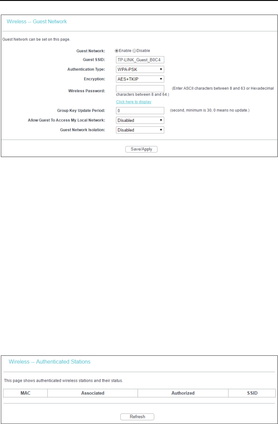
TD-W8960N User Guide
67
You can enable or disable Guest Network. When you enable this function, you could set wireless
parameters for Guest Network.
Guest SSID: The guest network name. When setting up a Guest network, it is strongly
recommended to use a name that easily distinguishes it from your primary network.
Authentication Type: Select the Authentication Type from the drop-down list.
Encryption: You can select either AES, or AES+TKIP.
Wireless Password: Enter the wireless password for the Guest Network as you like. You
also can click Click here to display to see the wireless password.
Group Key Update Period: Specify the group key update interval in seconds. The value
should be 30 or above. Enter 0 to disable the update.
Allow Guest To Access My Local Network: The guests have access to your Local Network,
but cannot login the modem router’s web management interface.
Guest Network Isolation: This function can isolate wireless clients on your guest network
from each other. Client isolation is disabled by default.
Click Save/Apply to make the settings effective.
4.6.2 Station list
Go to Guest Network → Station list, you can see the MAC Address, Associated, Authorized and
SSID.
MAC: Displays the connected wireless station's MAC address.
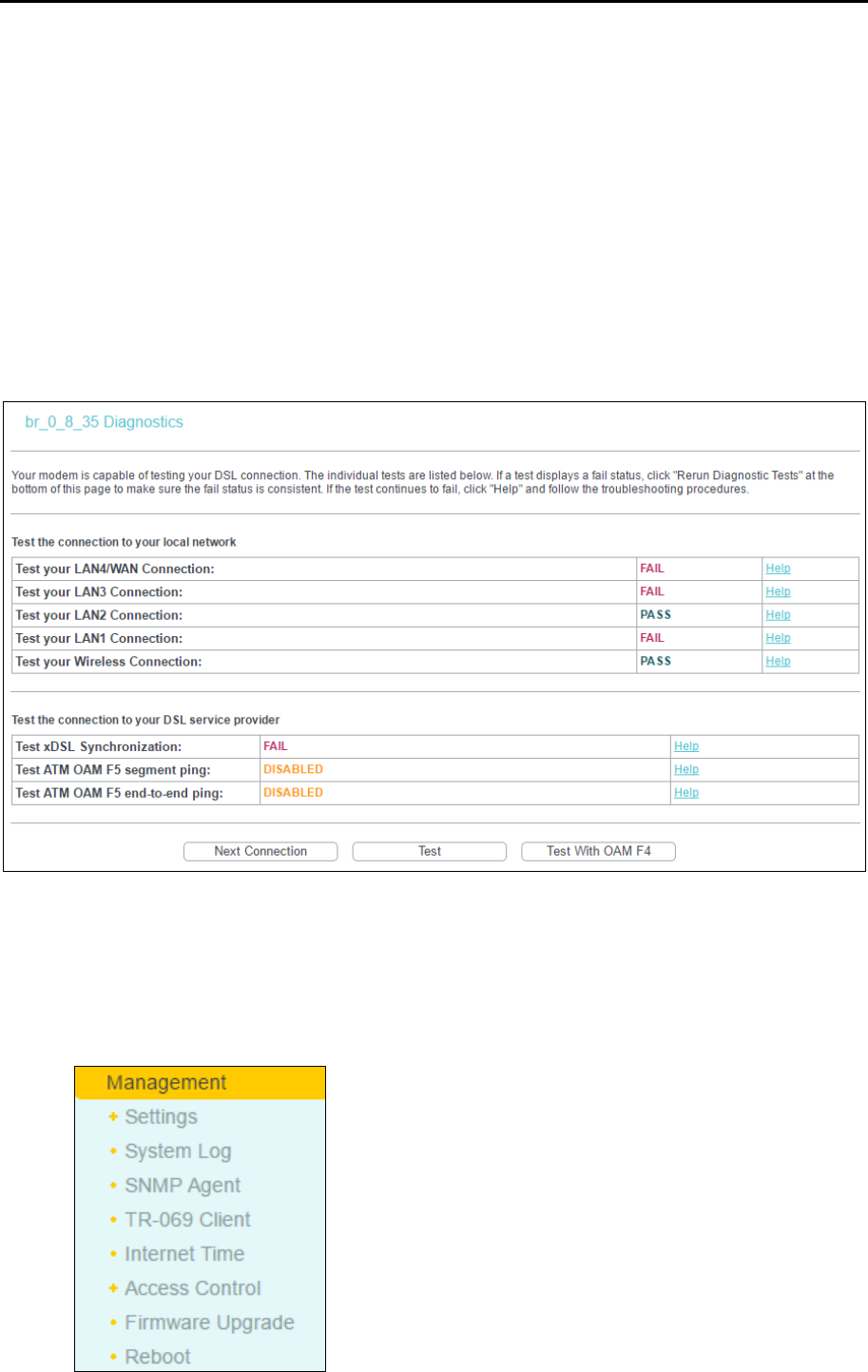
TD-W8960N User Guide
68
Associated: Displays whether the wireless station has associated with the access point.
Authorized: Displays the information of Authentication.
SSID: Displays the connected wireless network's SSID.
You cannot change any of the values on this page. To update this page and to show the current
connected wireless stations, click Refresh.
4.7 Diagnostics
Go to Diagnostics, you will see the Diagnostics screen. This section describes the result of the test
for the ENET (Ethernet) Connection, Wireless Connection and ADSL Synchronization. You can
refer to the Help menu to get more information about the corresponding test.
4.8 Management
Go to Management, there are eight submenus under the main menu. They are Settings, System
Log, SNMP Agent, TR-069 Client, Internet Time, Access Control, Update Firmware and Reboot.
Click any of them, and you will be able to configure the corresponding function.
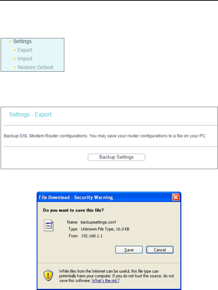
TD-W8960N User Guide
69
4.8.1 Settings
This section provides three important functions for managing the router; they are Export, Import
and Restore Default. The detailed manipulations are described below.
4.8.1.1 Export
Go to Management → Settings → Export, you can see the Export screen, which allows you to
save the current configuration of the router as a backup file.
To back up the router’s current settings:
1. Click Backup Settings, the following screen will then appear.
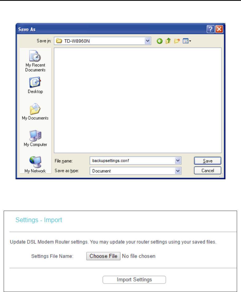
TD-W8960N User Guide
70
2. Click Save, and save the file as the appointed file.
4.8.1.2 Import
Go to Management → Settings → Import, you can update the router’s settings.
To update the router’s settings:
1. Click Choose File to locate the update file for the device, and you can also enter the exact
path to the Setting file in the text box.
2. After you have selected the file for updating the settings, click Import Settings.
Note:
The router will reboot upon completion. This process will take a while, don’t turn off the router or press
the Reset button while processing.
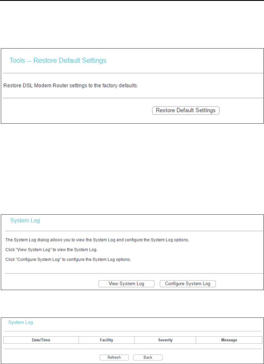
TD-W8960N User Guide
71
4.8.1.3 Restore Default
Go to Management → Settings → Restore Default, you can restore the router’s configuration to
the factory defaults on the screen.
Restore Default Settings: Click to restore the router’s configuration to the factory defaults,
and then follow the on-screen instructions to complete it.
Account and Password: The default account name and password are both admin.
The default IP Address: 192.168.1.1.
The default Subnet Mask: 255.255.255.0.
4.8.2 System Log
Go to Management → System Log, you can view the system log and configure the system log
options.
To View the System Log:
Click View System Log, you will see the screen which displays the router’s recent logs.
Refresh: Click the button, the information in the table will be updated.
Back: Click the button, the screen will back to the previous page.
To Configure the System Log Settings:
Click Configure System Log, you will see the screen below.
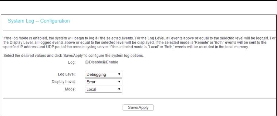
TD-W8960N User Guide
72
Disable/Enable: Select the Enable to log the events, if you don’t want to log these events,
select Disable.
Log Level: Select the Log level in the drop-down list, for the Log level, all events above or
equal to the selected level will be logged.
Display Level: Select the Display level in the drop-down list, for the Display Level, all logged
events above or equal to the selected level will be displayed.
Mode: Select the mode to record the events. If the selected mode is Local, events will be
recorded in the local memory. If the selected mode is Remote, events will be sent to the
specified IP address and UDP port of the remote system log server. If the selected mode is
Both, events will be sent to the local memory and the remote system log server.
4.8.3 SNMP Agent
Go to Management → SNMP Agent, you can see the SNMP-Configuration screen as shown
below.
SNMP (Simple Network Management Protocol) has been widely applied in the computer networks
currently, which is used for ensuring the transmission of the management information between
any two nodes. In this way, network administrators can easily search and modify the information
on any node on the network. Meanwhile, they can locate faults promptly and implement the fault
diagnosis, capacity planning and report generating.
An SNMP Agent is an application running on the router that performs the operational role of
receiving and processing SNMP messages, sending responses to the SNMP manager, and
sending traps when an event occurs. So a router containing SNMP "agent" software can be
monitored and/or controlled by SNMP Manager using SNMP messages.
An SNMP Manager or SNMP Service is an application that performs the operational roles of
generating SNMP messages/requests to modify and retrieve management information, and
receiving the requested information and trap-event reports that are generated by the SNMP agent.
SNMP Manager is the third-party management system. Monitor one is an SNMP Manager.
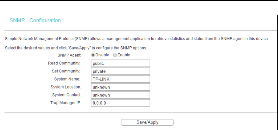
TD-W8960N User Guide
73
SNMP Agent: You can select the checkbox to disable or enable the function.
Note:
SNMP Community string provides a simple method of authentication between the router (SNMP Agent)
and a remote network manager (SNMP Manager). You can specify the community string as the
password to authenticate the management station to the router.
Read Community: This field allows you to specify the SNMP Community string which
provides read-only access to the router that the community is only permitted to read the device
configuration. The default value is “public”.
Set Community: This field allows you to specify the SNMP Community string which provides
read and write access to the router that the community has the authority to read and change
the device configuration. The default value is “private”.
System Name: Enter alphanumeric string to specify an SNMP community string name. Your
router (SNMP agents) will expose management data on the managed systems as this "system
name".
System Location: The person to notify when problems occur.
System Contact: The location of the person that is identified as the system contact.
Trap Manager IP: Enter the IP address of the SNMP Manager,where the SNMP Agent
forwards trap notifications.
Select the desired values and click Save/Apply to configure the SNMP options.
4.8.4 TR-069 Client
Go to Management → TR-069 Client, you can see the TR-069 client screen as shown below.
TR-069(WAN Management Protocol)allows an Auto-Configuration Server (ACS) to perform
auto-configuration, provision, collection, and diagnostics to this device.
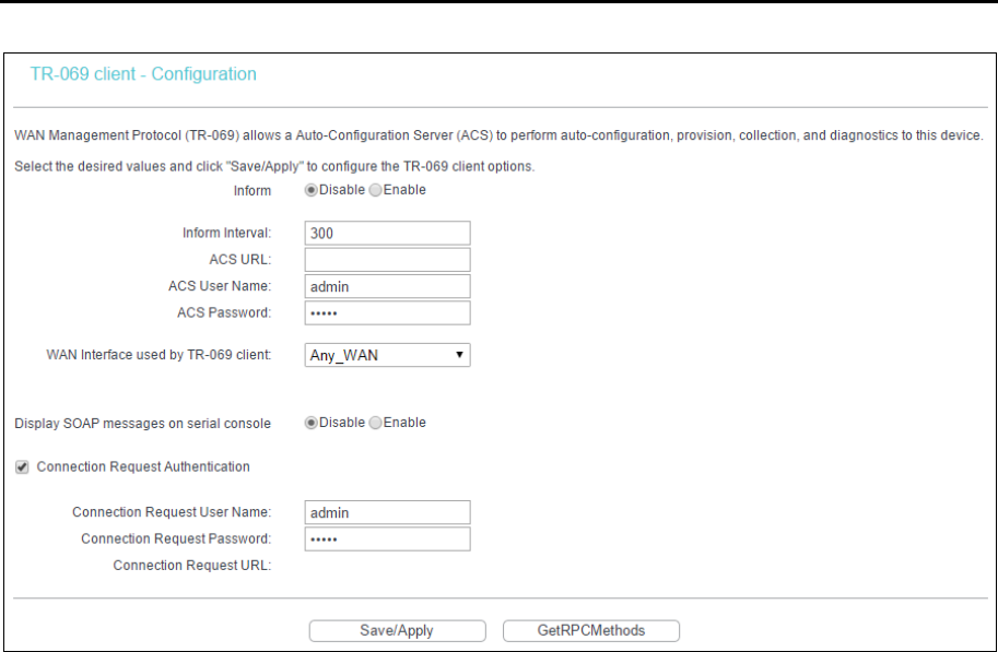
TD-W8960N User Guide
74
Inform: You can select the checkbox to disable or enable the function of TR-069 client.
Inform Interval: Type the interval time of your router contact with the ACS.
ACS URL: Please accept this information from your ISP. And through ACS
(Auto-Configuration Server) you can perform auto-configuration, provision, collection, and
diagnostics to this router.
ACS User Name: Please accept this User Name information from your ISP.
ACS Password: Please accept the Password information from your ISP.
Note:
If you want to log on the ACS, you must own the ACS User Name and ACS Password.
WAN Interface used by TR-069 Client: Please select the WAN Interface from the drop-down
list to perform this function.
Connection Request User Name: Type the Connection Request User Name, set it yourself.
Connection Request Password: Type the Connection Request Password, set it yourself.
Note:
The Connection Request User Name and Connection Request Password are used for ACS log on the
router and manage it.
Select the desired values and click Save/Apply to configure the TR-069 client options.
4.8.5 Internet Time
Go to Management → Internet Time, you can configure the time of the router.
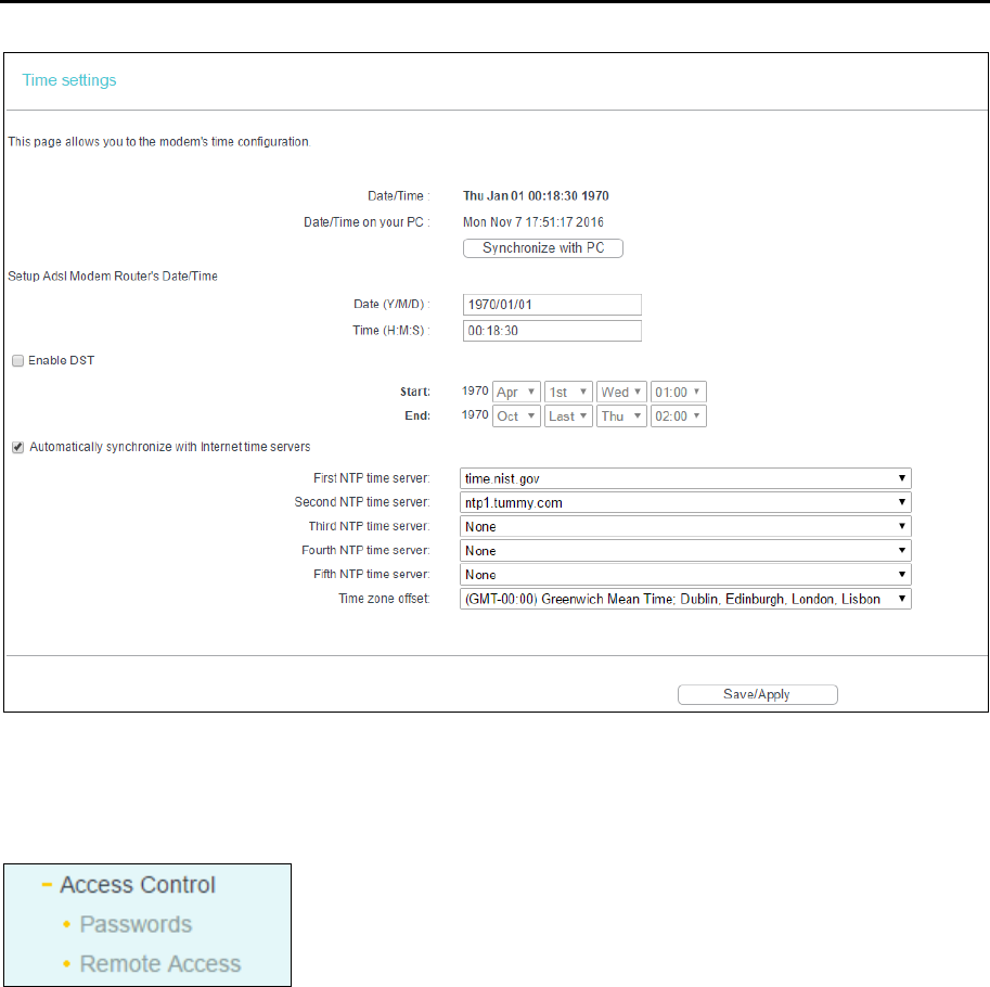
TD-W8960N User Guide
75
Enable DST: Select the checkbox to enable daylight saving function.
4.8.6 Access Control
There are two submenus under the Access Control menu: Passwords and Remote Access. The
detailed explanations for each submenu are provided below.
4.8.6.1 Password
Go to Management → Access Control → Password, you can change the factory default password
of the router. The default password is the same as the user name, which is admin/admin,
support/support, and user/user respectively.
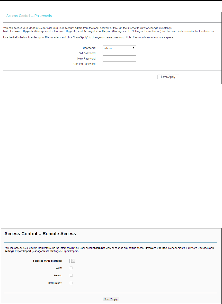
TD-W8960N User Guide
76
To change the password:
1. Enter the Old Password in the text box.
2. Enter the New Password and Confirm Password. The Confirm Password should be the same
as the New Password.
3. Click Save/Apply to make your change take effect.
Note:
1) Access to your DSL modem router is controlled through the account admin. You have unrestricted
access to change and view configuration of your DSL modem router if you access from the local
area network. If you access via the internet, Firmware Upgrade (Management > Firmware Upgrade)
and Settings Export/Import (Management > Settings > Export/Import) functions are unavailable
2) Admin can do remote management. For security reasons, please change its default password
when remote access function is enabled.
3) The password cannot contain a space, and its maximum length is 16 characters.
4.8.6.2 Remote Access
Go to Management → Access Control → Remote Access, you can see the screen which allows
you to change the factory default password of the router.
Web:Select this box, you can access your modem router via web.
Telnet: Select this box, you can access your modem router via command line.
ICMP(ping): Select this box, PC in public network can ping the WAN address of the modem
router.
Click Save/Apply to make your change take effect.
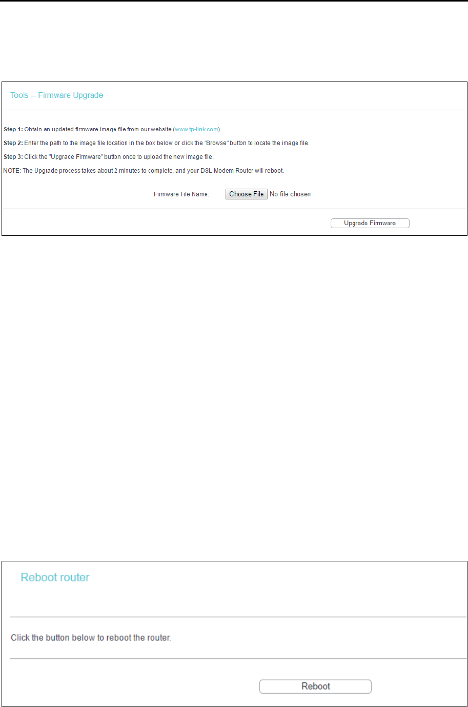
TD-W8960N User Guide
77
4.8.7 Firmware Upgrade
Go to Management → Firmware Upgrade, you can see the screen which allows you to upgrade
the latest version software to keep the router up to date.
Choose File: Click the button to locate the latest software for the device.
Upgrade Firmware: After you have selected the latest software, click the button.
To upgrade the router's software:
1. Download the latest software upgrade file from the TP-Link website (http://www.tp-link.com).
2. Click Choose File to view the folders and select the image file or enter the exact path to the
image file location in the text box.
3. Click Upgrade Firmware.
Note:
1) There is no need to upgrade the firmware unless the new firmware has a new feature you want to
use. However, when experiencing problems caused by the router itself, you can try to upgrade the
firmware.
2) Before upgrading the router’s firmware, you should write down some of your customized settings
to avoid losing important configuration settings of the router.
3) Do not turn off the router or press the RESET button while the software is being updated.
4) The router will reboot after the Upgrading is finished.
4.8.8 Reboot
Go to Management → Reboot, you can see the screen which allows you to reboot the router.
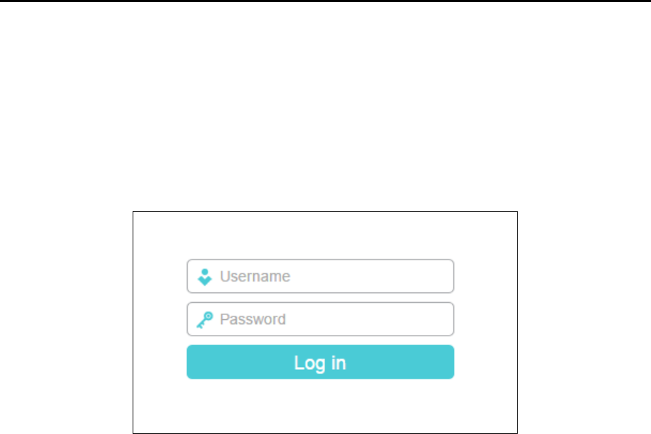
TD-W8960N User Guide
78
Note:
1) After you click the Reboot button, please wait for a while before reopening your web browser.
2) Do not turn off or reset the router while it is rebooting.
3) If necessary, reconfigure your PC's IP address to match your new configuration.
4.9 Logout
Go to Logout, and you will back to the login screen as shown below.
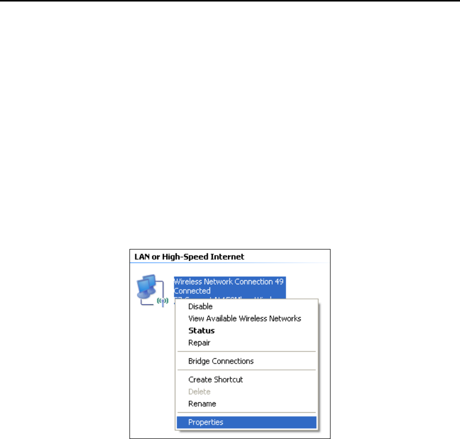
TD-W8960N User Guide
79
Appendix A: Configuring the PC
We’ll introduce how to install and configure the TCP/IP correctly on your computer. First make
sure your Ethernet Adapter is working, refer to the adapter’s manual if necessary.
The default IP address of the modem router is 192.168.1.1. And the default Subnet Mask is
255.255.255.0. These values can be changed as you desire. Here we use all the default values for
description and take Windows XP as example.
1. Configure TCP/IP component
1) On the Windows taskbar, click the Start button, and then click Control Panel.
2) Click the Network and Internet Connections icon, and then click on the Network
Connections tab in the appearing window.
3) Right click the icon that showed below, select Properties on the prompt page.
4) In the prompt page that showed below, double click on the Internet Protocol (TCP/IP).
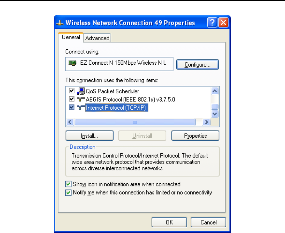
TD-W8960N User Guide
80
5) The following TCP/IP Properties window will display and the IP Address tab is open on
this window by default.
Now you have two ways to configure the TCP/IP protocol below:
Setting IP address automatically
Select Obtain an IP address automatically, Choose Obtain DNS server automatically, as shown in
the Figure below:
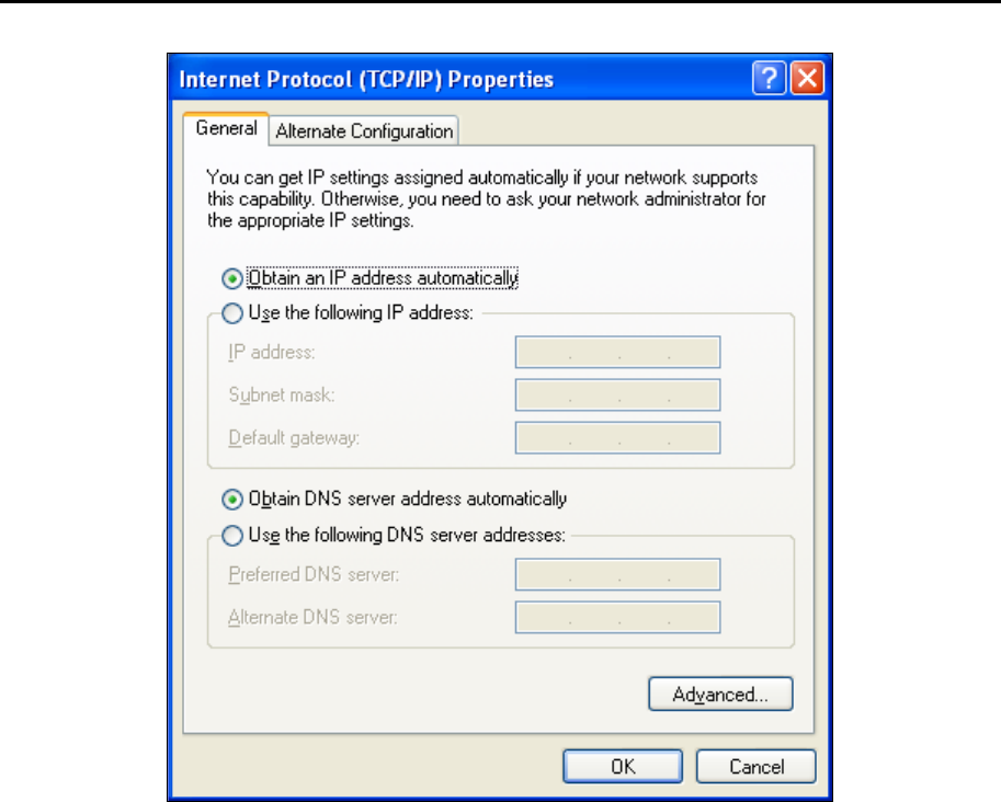
TD-W8960N User Guide
81
Setting IP address manually
1 Select Use the following IP address radio button. And the following items available
2 If the modem router's LAN IP address is 192.168.1.1, specify the IP address as 192.168.1.x (x
is from 2 to 254), and the Subnet mask as 255.255.255.0.
3 Type the modem router’s LAN IP address (the default IP is 192.168.1.1) into the Default
gateway field.
4 Select Use the following DNS server addresses. In the Preferred DNS Server field you can
enter the same value as the Default gateway or type the local DNS server IP address.
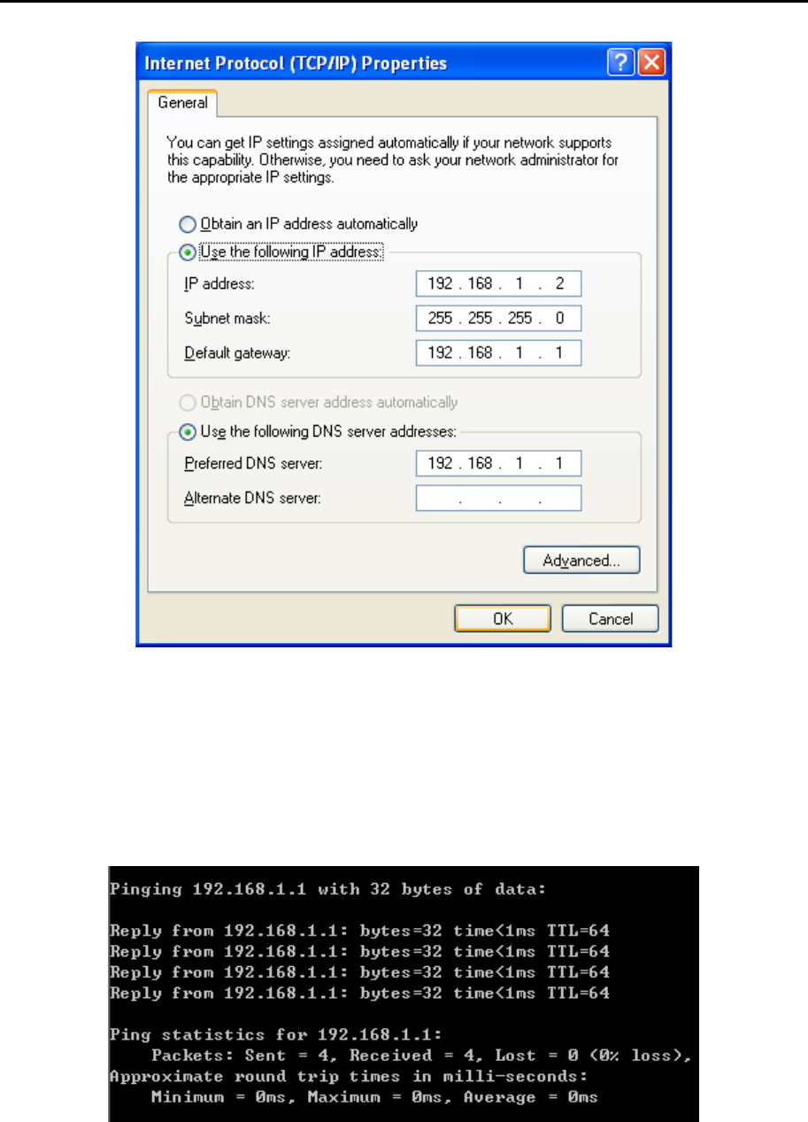
TD-W8960N User Guide
82
Now: Click OK to keep your settings.
2. Verify the network connection
Now, you can run the Ping command in the command prompt to verify the network connection.
Please click the Start menu on your desktop, select run tab, type cmd or command in the field and
press Enter. Type ping 192.168.1.1 on the following screen, and then press Enter.
If the result displayed is similar to the screen below, the connection between your PC and the
router has been established.
If the result displayed is similar to the screen shown below, it means that your PC has not
connected to the router.
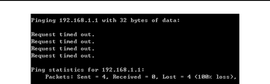
TD-W8960N User Guide
83
You can check it by following the steps below:
1) Is the connection between your PC and the router correct?
The LEDs of LAN port which you link to the device and the LEDs on your PC's adapter should
be lit.
2) Is the TCP/IP configuration for your PC correct?
If the router's IP address is 192.168.1.1, your PC's IP address must be within the range of
192.168.1.2 ~ 192.168.1.254.

TD-W8960N User Guide
84
Appendix B: Troubleshooting
T1. What can I do if I don’t know or forget my password?
- For default wireless password: Please refer to the Wireless Password/PIN labeled on the
bottom of the modem router.
- For the web management page password: Reset the modem router first and then use the
default username and password: admin/admin.
T2. How do I restore my modem router’s configuration to its factory default
settings?
Method one: With the modem router powered on, press and hold down the WPS/RESET button on
the rear panel of the modem router for more than 5 seconds and then release it. If all
LEDs turn on momentarily, you restore the modem router successfully.
Method two: Log in to the web management page of the modem router, and go to Management >
Settings > Restore Default, click Restore Default Settings and wait until the reset
process is complete.
Note:
Once the modem router is reset, the current configuration settings will be lost and you will need to
re-configure the router.
T3. What can I do if I cannot access the web management page?
Make sure the modem router connects to the computer correctly and the corresponding LED
indicator(s) light up.
Make sure the IP address of your computer is configured to obtain an IP address automatically
and obtain DNS server address automatically.
Make sure the default access is correctly entered in the address field.
Check your computer’s settings:
1) Go to Start → Control Panel → Network and Internet, and click View network status and
tasks;
2) Click Internet Options on the bottom left;
3) Click Connections, and select Never dial a connection;
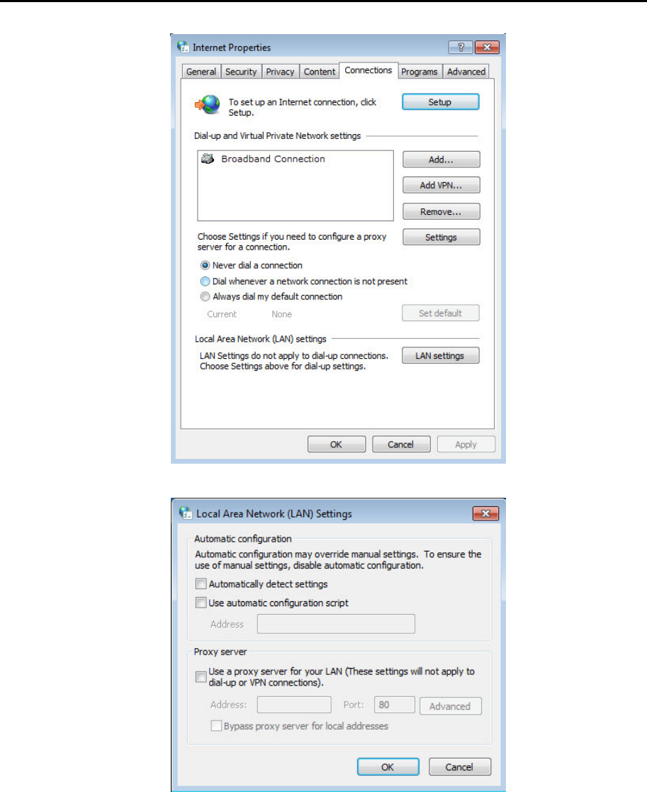
TD-W8960N User Guide
85
4) Click LAN settings, deselect the following three options and click OK;
5) Go to Advanced → Restore advanced settings, and click OK to save the settings.
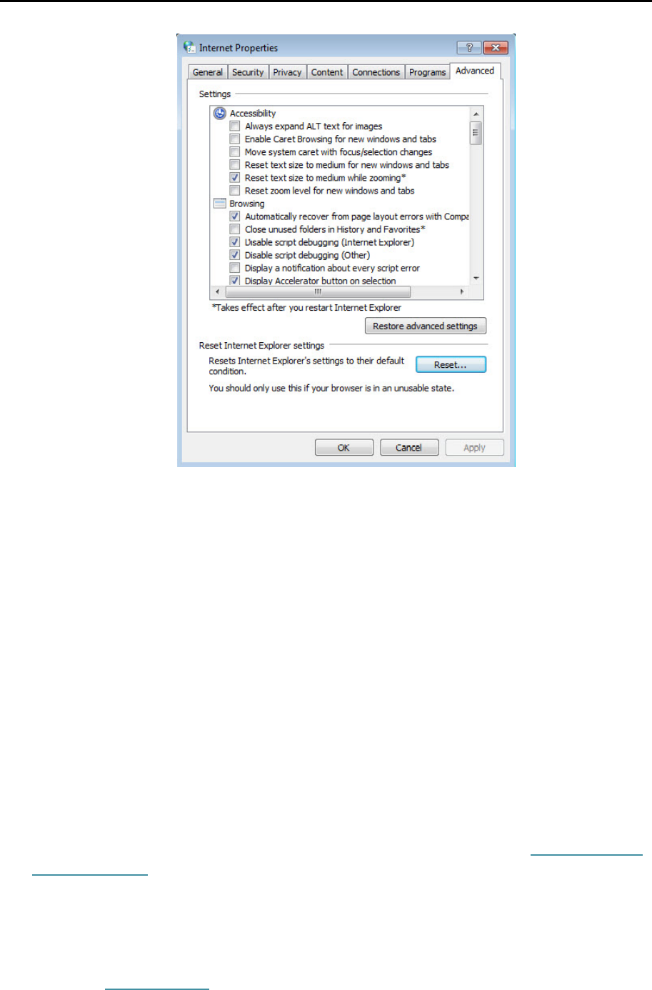
TD-W8960N User Guide
86
Change a web browser or computer and log in again.
Reset the modem router to factory default settings.
Note:
You’ll need to reconfigure the modem router to surf the internet once the modem router is reset.
Open a web browser and log in again. If login fails, please contact the technical support.
T4. What can I do if I cannot access the internet?
1) Check to see if all the connectors are connected well, including the telephone line, Ethernet
cables and power adapter.
2) Check to see if you can log in to the web management page of the modem router. If you can,
try the following steps. If you cannot, please set your computer referring to T3 then try to see if
you can access the internet. If the problem persists, please go to the next step.
3) Consult your ISP and make sure all the VPI/VCI, Connection Type, account username and
password are correct. If there are any mistakes, please correct the settings and try again..
4) If you still cannot access the internet, please restore your modem router to its factory default
settings and reconfigure your modem router by following the instructions in Chapter 3 Quick
Installation Guide.
5) Please feel free to contact our Technical Support if the problem persists.
Note:
For more details about Troubleshooting and Technical Support contact information, please refer to the
support page at www.tp-link.com.
