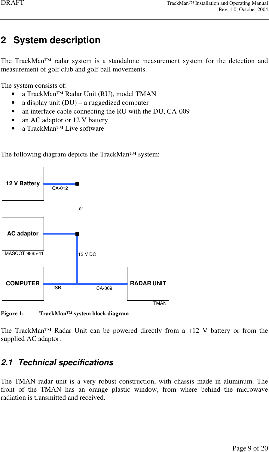
TrackMan A S TMAN Radar Unit for Sports Application User Manual TMAN Installation and Operating Manual

TrackMan A/S Radar Unit for Sports Application TMAN Installation and Operating Manual

Contents

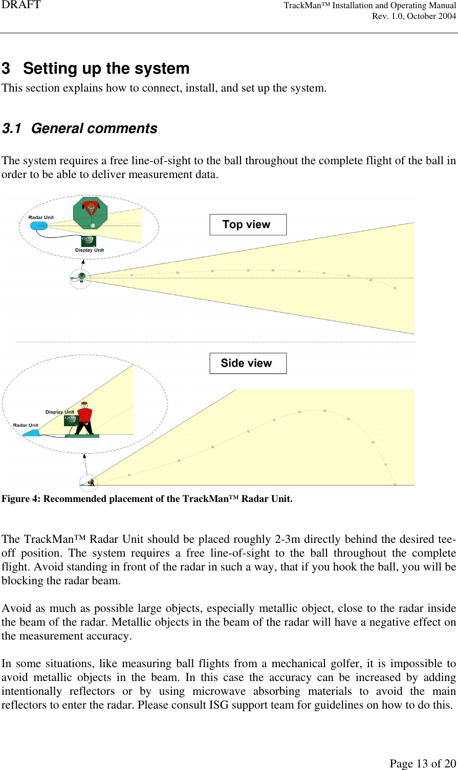
installation and operating manual

DRAFT   TrackMan™ Installation and Operating Manual     Rev. 1.0, October 2004       Page 1 of 20    TrackMan™ Radar Unit   Model: TMAN     Installation and Operating Manual Revision 1.0      ISG A/S                support@isg.dk
DRAFT   TrackMan™ Installation and Operating Manual     Rev. 1.0, October 2004       Page 2 of 20                              Information in this document is subject to change without notice.  Copyright © 2004 ISG A/S. All rights reserved.   Reproduction  in  any  manner  what  so  ever  without  the  written  permission  of  ISG  A/S  is strictly prohibited.  TrackMan™  is  a  registered  trademark  by  ISG  A/S.  Other  brands  and  product  names  are trademarks or registered trademarks of their respective holders.  ISG A/S has filed several patent applications which covers both the construction, operation and processing algorithms of the TrackMan™ system.   Model TMAN  September 2004  ISG/MANU/04001i1    Rev. 1.0
DRAFT   TrackMan™ Installation and Operating Manual     Rev. 1.0, October 2004       Page 3 of 20 REGULATORY NOTICE  FCC compliance This equipment  has  been tested  and  found  to  comply  with  the  limits for  a  Class  B  digital device, pursuant to part 15 of the FCC Rules. These limits are designed to provide reasonable protection against harmful interference in a residential installation. Operation is subject to the following two conditions:  1. This device may not cause harmful interference, and 2. this  device  must  accept  any  interference  received,  including  interference  that  may cause undesired operation.  This equipment generates, uses, and can radiate radio frequency energy and, if not installed and used in accordance with the instruction manual, may cause harmful interference to radio communications.  However,  there  is  no  guarantee  that  interference  will  not  occur  in  a particular installation. If this equipment does cause harmful interference to radio or television reception,  which  can  be  determined  by  turning  the  equipment  off  and  on,  the  user  is encouraged to try to correct the interference by one or more of the following measures: -Reorient or relocate the receiving antenna. -Increase the separation between the equipment and receiver. -Connect the equipment into an outlet on a circuit different from that to which the receiver is connected. -Consult the dealer or an experienced radio/TC technician for help.   Caution Never try to open or repair the device yourself. Any changes or modifications not expressly approved by ISG A/S could void the user’s authority to operate the device.
DRAFT   TrackMan™ Installation and Operating Manual     Rev. 1.0, October 2004       Page 4 of 20 WARNING: RADIATION HAZARD  Radiation Safety Warning. This  device  radiates  a  low  level  of  microwave  electromagnetic  radiation  from  the  front window  when  in  use.  The  radiated  power  is  significantly  lower  the  international  safety standards for microwave frequencies. However, the user should maintain a minimum distance of 20 cm from this device during operation.
DRAFT   TrackMan™ Installation and Operating Manual     Rev. 1.0, October 2004       Page 5 of 20 CAUTION: SAFETY INSTRUCTIONS  Use the following safety instructions to ensure your own personal safety and to help protect the TrackMan™ radar unit.   General • Do not attempt to service the device yourself. Always follow installation instructions closely. • Only use cables and accessories approved by ISG A/S together with your TrackMan™ Radar Unit. • Always connect all cables before turning on power for the TrackMan™ system. • The AC adaptor may become hot during normal operation of the TrackMan™ system. Use care when handling the adaptor during or immediately after operation. • When operating the TrackMan™ system outside in direct sunlight, the metallic chassis of  the  TrackMan™  Radar  Unit  may  become  hot.  Use  care  when  moving  the TrackMan™ Radar Unit in this case. • If the TrackMan™ system has been used in wet weather, clean all items with a dry cloth after use.  • During  use  and  transportation  of  the  TrackMan™  Radar  Unit,  avoid  bumping  into obstacles with the orange plastic front.  • When not using  the TrackMan™  Radar  Unit, avoid any  kind  of load at  the orange front, since this might damage the radar.  Power • Only use the AC adaptor supplied with the TrackMan™ Radar Unit. Use of another adaptor may cause fire or explosion. • Before you connect the TrackMan™ Radar Unit to an electrical outlet, check the AC adaptor  voltage  rating  to  ensure  that  the  required  voltage  and  frequency  match  the available power source. • To  help  prevent  electric  shock,  plug  the AC  adaptor  and  device  power  cables  into properly grounded power sources. These power cables may be equipped with 3-prong plugs to provide an earth grounding connection. Do not use adaptor plugs or remove the grounding prong from the power cable plug. If you use a power extension cable, use the appropriate type, 2-prong or 3-prong, to mate the AC adaptor power cable. • Make  sure  that  the  computer  and  AC adaptor  connected  to  the TrackMan™  Radar Unit are connected to the same power outlet. Failure to comply with this requirement could cause electrical shock and create permanent damage on both the TrackMan™ Radar Unit and the computer. • Place the AC adaptor in a ventilated and dry area. Do not cover the AC adaptor that will reduce cooling. • Be sure that nothing rests on your AC adaptors power cable and that the cable is not located where it can be tripped over or stepped on.   ISG A/S accepts no liability for failure to comply with these requirements.
DRAFT   TrackMan™ Installation and Operating Manual     Rev. 1.0, October 2004       Page 6 of 20 WARRANTY COMMENT  The TrackMan™ Radar Unit contains no user serviceable parts inside. In case of defect or malfunctioning  TrackMan™  Radar  Unit,  the  unit  must  be  repaired by  ISG  A/S  authorized personal ONLY.   IMPORTANT  The  box  is  sealed  to  prevent  unauthorized  access  to  the  inside  of  the TrackMan™  Radar  Unit.  If  the  sealed  is  broken  any  warranty  agreement  will  terminate immediately. Warranty will also terminate immediately if: -Use of non-approved AC adaptor or incorrect direct applied DC voltage -Use of non-approved cables between the TrackMan™ Radar Unit and the computer -If the TrackMan™ Radar Unit is not installed or operated in compliance with this manual.  For full description of the warranty and the scope hereof, reference is made to the warranty agreement between the user and ISG A/S.
DRAFT   TrackMan™ Installation and Operating Manual     Rev. 1.0, October 2004       Page 7 of 20  TABLE OF CONTENTS   1  INTRODUCTION............................................................................................................................. 8 2  SYSTEM DESCRIPTION................................................................................................................... 9 2.1  Technical specifications ...................................................................................................... 9 3  SETTING UP THE SYSTEM ............................................................................................................ 13 3.1  General comments............................................................................................................. 13 3.2  Step-by-step setup ............................................................................................................. 14 3.3  Leveling............................................................................................................................. 14 4  END OF USE................................................................................................................................. 16 5  TROUBLESHOOTING.................................................................................................................... 17 6  TRANSPORTATION, STORAGE AND MAINTENANCE ...................................................................... 19 6.1  Transportation.................................................................................................................... 19 6.2  Maintenance ...................................................................................................................... 19 6.3  Storage............................................................................................................................... 20
DRAFT   TrackMan™ Installation and Operating Manual     Rev. 1.0, October 2004       Page 8 of 20 1  Introduction  This document provides instructions on how to setup, operate, maintain, and troubleshoot the TrackMan™ system.  This document does not describe the TrackMan™ application software and how to operate it. This is provided in separate document.
DRAFT   TrackMan™ Installation and Operating Manual     Rev. 1.0, October 2004       Page 9 of 20 2  System description  The  TrackMan™  radar  system  is  a  standalone  measurement  system  for  the  detection  and measurement of golf club and golf ball movements.  The system consists of: • a TrackMan™ Radar Unit (RU), model TMAN  • a display unit (DU) – a ruggedized computer • an interface cable connecting the RU with the DU, CA-009 • an AC adaptor or 12 V battery • a TrackMan™ Live software   The following diagram depicts the TrackMan™ system:  AC adaptorRADAR UNITTMANCOMPUTERMASCOT 9885-41CA-009USB12 V DCCA-01212 V Batteryor Figure 1:  TrackMan™ system block diagram  The  TrackMan™  Radar  Unit  can  be  powered  directly  from  a  +12  V  battery  or  from  the supplied AC adaptor.   2.1  Technical specifications  The  TMAN  radar  unit  is  a  very robust  construction,  with  chassis  made  in  aluminum.  The front  of  the  TMAN  has  an  orange  plastic  window,  from  where  behind  the  microwave radiation is transmitted and received.
DRAFT   TrackMan™ Installation and Operating Manual     Rev. 1.0, October 2004       Page 10 of 20  Figure 2: TrackMan™ radar unit, model TMAN front view  The TrackMan™ Radar Unit also has a  built-in  digital  camera, which looks out  through a window in the front.  WARNING !  Make sure that the orange front and the camera window of the TrackMan™ Radar Unit is handled with care. Avoid any load or bumping into with the front of the TrackMan™ Radar Unit.
DRAFT   TrackMan™ Installation and Operating Manual     Rev. 1.0, October 2004       Page 11 of 20 TrackMan™ Radar Unit , model TMAN  Operating Frequency  10.500-10.550 GHz, factory fixed Transmitter power  10 mW Antenna gain  17 dB Horizontal beam width  23 degrees Vertical beam width  19 degrees Dimensions  Width:  410 mm (16.1”) Depth:  125 mm (4.9”) Height:  320 mm (12.6”) Mass  ~10 kg (22 lbs) Main power supply  10.5-18 V DC, 25W maximum Data interface  USB2.0 high speed Environmental  -5 degC to +45 degC ambient 100% humidity  The TrackMan™ Radar Unit consists of the following sub-assemblies and/or printed circuit board assemblies: • Microwave transmitter • Microwave receivers with video amplifiers • Antennas for transmitting and receiving • Analog to digital converters • Adjustable legs with motors • Servo board • Digital camera • Power stabilizing circuit  The TrackMan™ Radar Unit is splash proof and is designed to withstand rain showers. When using the TrackMan™ system in wet weather it might be necessary to dry of water drops at camera window, in order to get proper pictures of the landing field.   The TrackMan™ Radar Unit has two motorized legs for leveling the radar unit.  The connector input, the motor switch and two LED’s are covered behind the orange plate of the back of the TrackMan™ Radar Unit.
DRAFT   TrackMan™ Installation and Operating Manual     Rev. 1.0, October 2004       Page 12 of 20 Figure 3: TrackMan™ radar unit, model TMAN back side view   Display Unit (DU)  The DU must have the following minimum specifications: -Operating system Microsoft Windows XP SP1 or later, UK version -USB2.0 high speed port -CD/DVD drive -Minimum Pentium 4 2.0 GHz or Pentium M 1.4 GHz -Minimum 256 MB ram -Screen resolution 1024x768, 24 bit -Minimum 50 MB free hard disk space  The TrackMan™ system can be used in conjunction with the TrackMan™ R&D toolbox for post analysis of the raw data files. In this case, it is recommended to have at least 1 GB free hard disk space for data files storage.  The  DU  for  the  TrackMan™  is  normally  delivered  by  ISG  A/S.  During  operation  of  the TrackMan™ system, the computer must ONLY run the TrackMan™ application, since this will  require  the  full  processing  power  of  the  computer.  If  other  programs  are  running simultaneously  with  the  TrackMan™  application,  the  operation  of  the  system  might  be impossible.
DRAFT   TrackMan™ Installation and Operating Manual     Rev. 1.0, October 2004       Page 13 of 20 3  Setting up the system This section explains how to connect, install, and set up the system.   3.1  General comments  The system requires a free line-of-sight to the ball throughout the complete flight of the ball in order to be able to deliver measurement data.   Figure 4: Recommended placement of the TrackMan™ Radar Unit.   The TrackMan™ Radar Unit should be placed roughly 2-3m directly behind the desired tee-off  position.  The  system  requires  a  free  line-of-sight  to  the  ball  throughout  the  complete flight. Avoid standing in front of the radar in such a way, that if you hook the ball, you will be blocking the radar beam.   Avoid as much as possible large objects, especially metallic object, close to the radar inside the beam of the radar. Metallic objects in the beam of the radar will have a negative effect on the measurement accuracy.   In some situations, like measuring ball flights from a mechanical golfer, it is impossible to avoid  metallic  objects  in  the  beam.  In  this  case  the  accuracy  can  be  increased  by  adding intentionally  reflectors  or  by  using  microwave  absorbing  materials  to  avoid  the  main reflectors to enter the radar. Please consult ISG support team for guidelines on how to do this.
DRAFT   TrackMan™ Installation and Operating Manual     Rev. 1.0, October 2004       Page 14 of 20 NOTE!  Some  types  of  fluorescent  light  tubes  emit  significant  electromagnetic  noise. Placement  of  the  TrackMan™  Radar  Unit  nearby  such  types  of  light  tubes  will  have  a negative influence on the tracking capability of the TrackMan™ system.    3.2  Step-by-step setup  In order for the system to function properly, it has to be set up in the correct way, and in the correct order: 1. Place the TrackMan™ Radar Unit and DU where you want them roughly to be. Turn on the DU 2. Pull  out  the  two  legs  of  the  TrackMan™  Radar  Unit  until  you  hear  a  click.  This indicates that the legs are safely fastened in their sockets. If the legs are at different lengths,  don’t  be  alarmed.  This  is  merely  a  result  from  the  last  time  the  unit  was operated. 3. Tip out the orange leg on the back of the TrackMan™ Radar Unit about 120 deg until it snaps in place. Now the leg should be locked in place. 4. Align  the  front  of  the  TrackMan™  Radar  Unit  roughly  in  the  desired  ball  flight direction. 5. Connect  the  TrackMan™  Radar  Unit  to  the  DU’s  USB  port  and  connect  the  AC adaptor as well. 6. Turn on the power to the TrackMan™ Radar Unit. Make sure that the power LED on the TrackMan™ Radar Unit is green. 7. Engage  the  motor  switch  in  the  back  of  the  TrackMan™  Radar  Unit  to  initiate  the leveling mechanism. You should now hear a low motor sound, indicating that leveling is taking place. When level LED is green and the motors are quite, correct leveling has taken place. 8. Turn  off  the  motor  switch,  in  order  to  avoid  unintentional  movement  of  the  radar during measurement. 9. Start the TrackMan™ application software  The final horizontal alignment happens from within the TrackMan™ application software.  Depending on type of computer being used, it might be required to place the computer on a table to make sure moisture does not enter the computer. Please check with the guidelines for the computer.  If it is raining, make sure that the computer and the AC adaptor is placed under cover. To avoid malfunction, make sure that the computer is kept clean and dry.  3.3  Leveling  When  the  switch  is  on,  the  internal  servo  will  insure  that  the  TrackMan™  Radar  Unit  is leveled. The legs operate at a speed of approximately ¼ mm a second. If the system is very far from leveled, it might take some time to level the TrackMan™ Radar Unit.
DRAFT   TrackMan™ Installation and Operating Manual     Rev. 1.0, October 2004       Page 15 of 20  The  legs  can  also  be  manually  adjusted,  just  turn  the  legs  with  your  hands.  The  manual adjustment of the legs can even take place when the motors are turned on.  If the TrackMan™ Radar Unit is placed on a extremely unleveled ground, the legs might get fully extended or compressed. This might cause the legs to get out of grip with the motor axis. This is not harmful in anyway to the mechanics of the TrackMan™ Radar Unit. In this case simply make a few turns of the leg with your hands while pushing/pulling slightly in the leg to get a grip.  If  the  motors in the  TrackMan™  Radar  Unit  are  moving  while  the  TrackMan™  system  is measuring, distortion in the recorded signal might occur. To avoid this, switch off the motors while measuring.   It should be avoided to place the TrackMan™ Radar Unit on a non-solid ground, like wooden terrace or similar. If it is done anyway, make sure to switch of the motors while measuring, since the TrackMan™ Radar Unit might get into mechanical oscillating vibration which will have a negative influence on the recorded signals.  At any time the motors can be turned on in order to verify that the radar is still leveled.
DRAFT   TrackMan™ Installation and Operating Manual     Rev. 1.0, October 2004       Page 16 of 20 4  End of use  When terminating a session with the TrackMan™ system, please follow these steps:  1. Exit the TrackMan™ application software  2. Turn off the motor switch of the TrackMan™ Radar Unit 3. Turn of the power to the TrackMan™ Radar Unit 4. Disconnect the cables to the TrackMan™ Radar Unit, by pulling the connector out. 5. Push  the  two  motorized  legs  into  the  box  by giving  the TrackMan™  Radar  Unit  a small knock on the top. Push the legs in as far as you can. 6. The backside leg is pulled out and up. Be careful not to get a finger caught when it snaps into place. Now the TrackMan™ Radar Unit is ready for stow.  Make sure that the TrackMan™ Radar Unit and DU are wiped dry, and that any mud and dirt is  removed.  The  system  will  not  be  damaged  by  water,  mud  or  dirt,  but  to  extend  the appearance and life time of the TrackMan™ Radar Unit it is advisable.
DRAFT   TrackMan™ Installation and Operating Manual     Rev. 1.0, October 2004       Page 17 of 20 5  Troubleshooting  Problem  The TrackMan™ Radar Unit does not seem to level correctly Step 1  Is  the  cable  connected  to  both  the  TrackMan™  Radar  Unit  and  the  power supply? Step 2  Make sure the AC adaptor for the radar is turned ON? Step 3  Is the motor switch ON and does the green light appear in the switch (might be a weak light)? Step 4  Has the motors reached its end stops? If yes re-position the radar at a more leveled place.   Problem  The TrackMan™ application software is not able to communicate with the Radar Unit. Step 1  Is  the  cable  connected  to  both  the  TrackMan™  Radar  Unit  and  the  power supply and is the power supply to the radar turned on? Step 2  Have you inserted the TrackMan™ Radar Unit in the assigned USB2.0 port on the computer? Note: the drivers for the TrackMan™ Radar Unit is dedicated to the USB port where the radar was connected during installation. Step 3  Is  there  a USB  hub  between  the  computer  USB  port  and  the  TrackMan™ Radar Unit. If yes, remove it. Step 4  Try to unplug the USB cable at the computer, wait a couple of seconds, and re-insert it again. Step 5  Consult the TrackMan™ application software diagnostic tools for more help   Problem  The  camera  pictures  from  the  TrackMan™  radar  Unit  seems  over exposed Step 1  Try position/orient the radar so the light intensity at the front of the radar is similar to the light intensity on the target field. Step 2  Try to increase the light intensity at the camera window by using a flash light or other high intensity light source while taking the pictures.   Problem  No triggering occurs when a golf ball is launched Step 1  Make sure that the power to the TrackMan™ Radar Unit is turned on and the radar is properly leveled. Make sure that the golf ball is being launched from the indicated area shown in the TrackMan™ application software. Step 2  Consult the TrackMan™ application software diagnostic tools for more help
DRAFT   TrackMan™ Installation and Operating Manual     Rev. 1.0, October 2004       Page 18 of 20  Problem  The measurement data seems incorrect. Step 1  Make sure that the golf ball is being launched from the indicated area shown in the TrackMan™ application software. Step 2  Make sure that the TrackMan™ is properly leveled and aligned at the desired target direction. Step 3  Make sure that the altitude of the golf ball being launched is within 5 cm of the surface that the TrackMan™ Radar Unit rests on. Step 4  Remove any solid objects in front of the TrackMan™ Radar Unit. Especially large  metallic  objects  like  golf  clubs,  golf  bags  or  other  instruments  can influence the data quality. Step 5  Consult the TrackMan™ application software diagnostic tools for more help
DRAFT   TrackMan™ Installation and Operating Manual     Rev. 1.0, October 2004       Page 19 of 20 6  Transportation, storage and maintenance  When unpacking the TrackMan™ Radar Unit from the original shipping box, remember to store the box for future use. The original shipping box must be used in case of return of unit for service or repair.   6.1  Transportation The  construction  of  the  TrackMan™  Radar  Unit  is  in  general  very  robust.  However,  the plastic  plate  in  the  front  of  the  radar  is  a  bit  more  sensitive.  During  transportation  the TrackMan™  Radar  Unit  should  be  protected  from  direct  shocks  and  bumps  on  the  front window.   The TrackMan™ Radar Unit is designed to fit into a carrier-on luggage for the airlines. It is recommended  to  enclose  the TrackMan™ Radar  Unit  with  foam  or  other  shock  absorbing materials when packed in a box or bag.  If the TrackMan™ Radar Unit is send by cargo, which is not recommended, allow for at least 50 mm of space from the metallic chassis of the TrackMan™ Radar Unit to the shipping box sides, by using heavy duty shock damping materials.   6.2  Maintenance  The  TrackMan™  Radar  Unit  has  been  constructed  in  robust  materials  with  minimum maintenance for years of outdoor usage.  The TrackMan™ Radar Unit contains only highly reliable electronic and mechanical systems that require no user maintenance.   When  the  two  legs  of  the  TrackMan™  Radar  Unit  are  extended  there  can  be  some  water, mud, or dirt on them after use. To remove this, use a soft cloth to wipe it of. There are two O-rings that make sure that no dirt, water or mud gets inside the TrackMan™ Radar Unit. If the legs are cleaned very thoroughly, a small amount of grease has to be added on the legs in front of the O-rings.   The front of the TrackMan™ Radar Unit can be wiped with a soft damp cloth. Make sure that the front plate is not damaged. In the case that the front plate is damaged DO NOT try to open the TrackMan™ Radar Unit, nor try to change the front plate.  WARNING! Security screws are mounted on the back of the TrackMan™ Radar Unit. If the seal is broken the warranty agreement will terminate immediately.  The  camera  window  has  to  be  cleaned  once  in  a  while.  Use  regular  window  cleaning detergent. Be careful not to scratch the window glass.
DRAFT   TrackMan™ Installation and Operating Manual     Rev. 1.0, October 2004       Page 20 of 20  The connector on the TrackMan™ Radar Unit as well as the connectors on the cables should be cleaned for dirt. Use compressed air and mild detergents to clean the connectors.  6.3  Storage  When not in use the TrackMan™ Radar Unit should for maximum lifetime be stowed at room temperature in a low humidity room.

Navigation menu